BMW X2 2018 Cars
Product's Documents
Below are documents related to this product, you can read online or download:
- Owner's manual - (English) Read Online | Download pdf
Owner's Guide Car
Buttons on the remote control
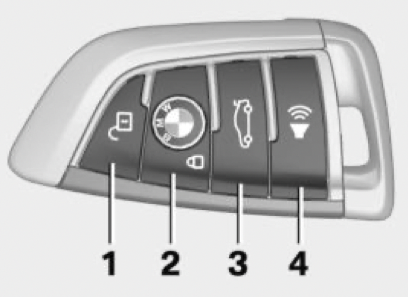
Unlocking the vehicle
 Press button on the remote control.
Depending on the settings, either only the driver's door or all vehicle access points are unlocked.
If only the driver's door is unlocked, press the button of the remote control again to unlock the other vehicle access points.
Press and hold this button on the remote control after unlocking.
The windows and the glass sunroof are opened, as long as the button on the remote control is pressed.
Locking the vehicle
 Press button on the remote control.
All vehicle access points are locked.
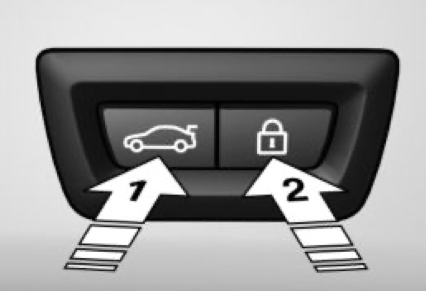
Buttons for the central locking system
Overview
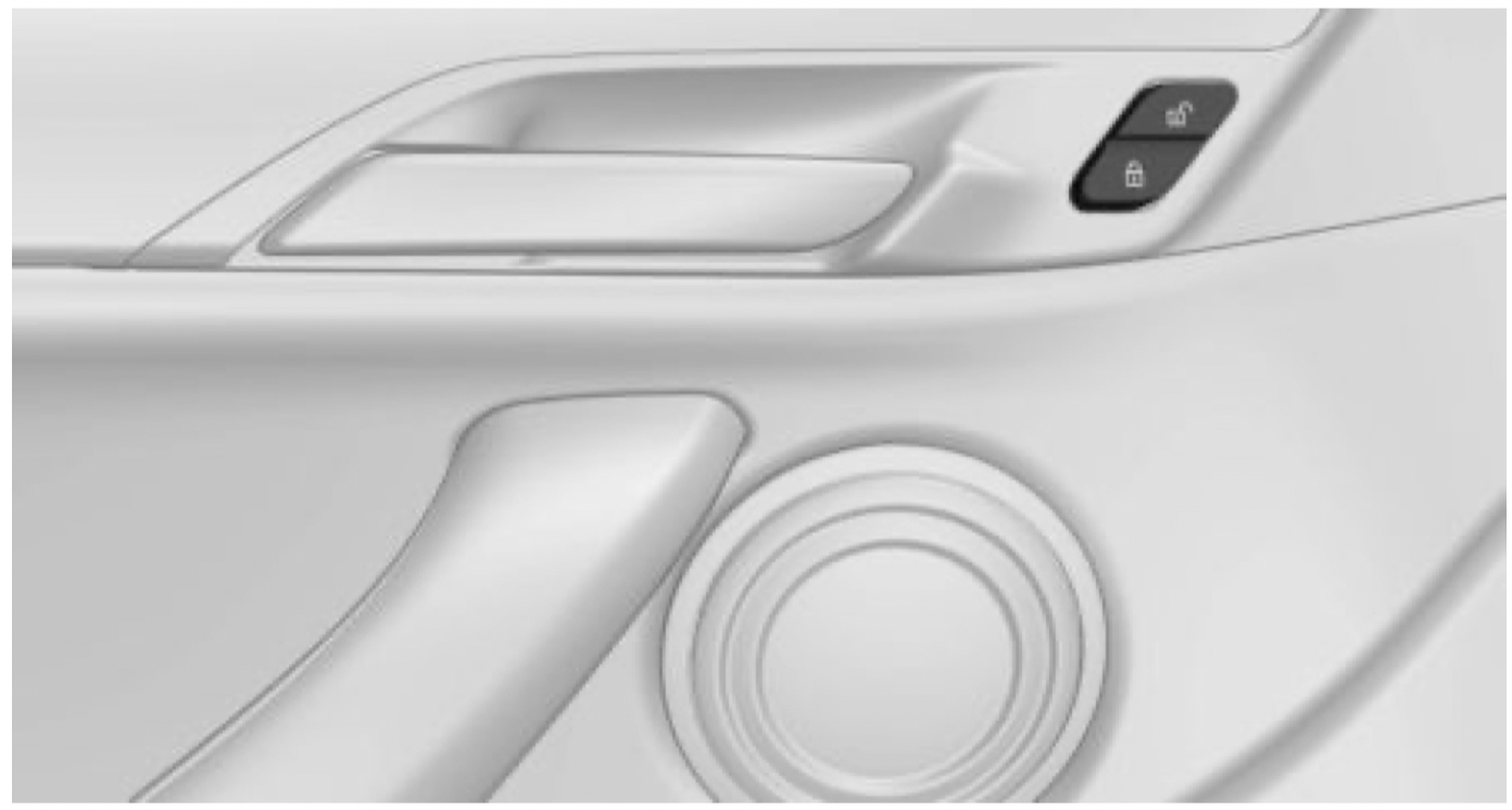
Locking
 Press the button with the front doors closed.
The fuel filler flap remains unlocked.
Unlocking
Press button.
Panic mode
You can trigger the alarm system if you find yourself in a dangerous situation.
 Press button on the remote control for at least 3 seconds.
To switch off the alarm: press any button.
Comfort Access
Concept
The vehicle can be accessed without activating the remote control.
All you need to do is to have the remote control with you, such as in your pants pocket.
The vehicle automatically detects the remote control when it is in close proximity or in the car's interior.
Unlocking the vehicle
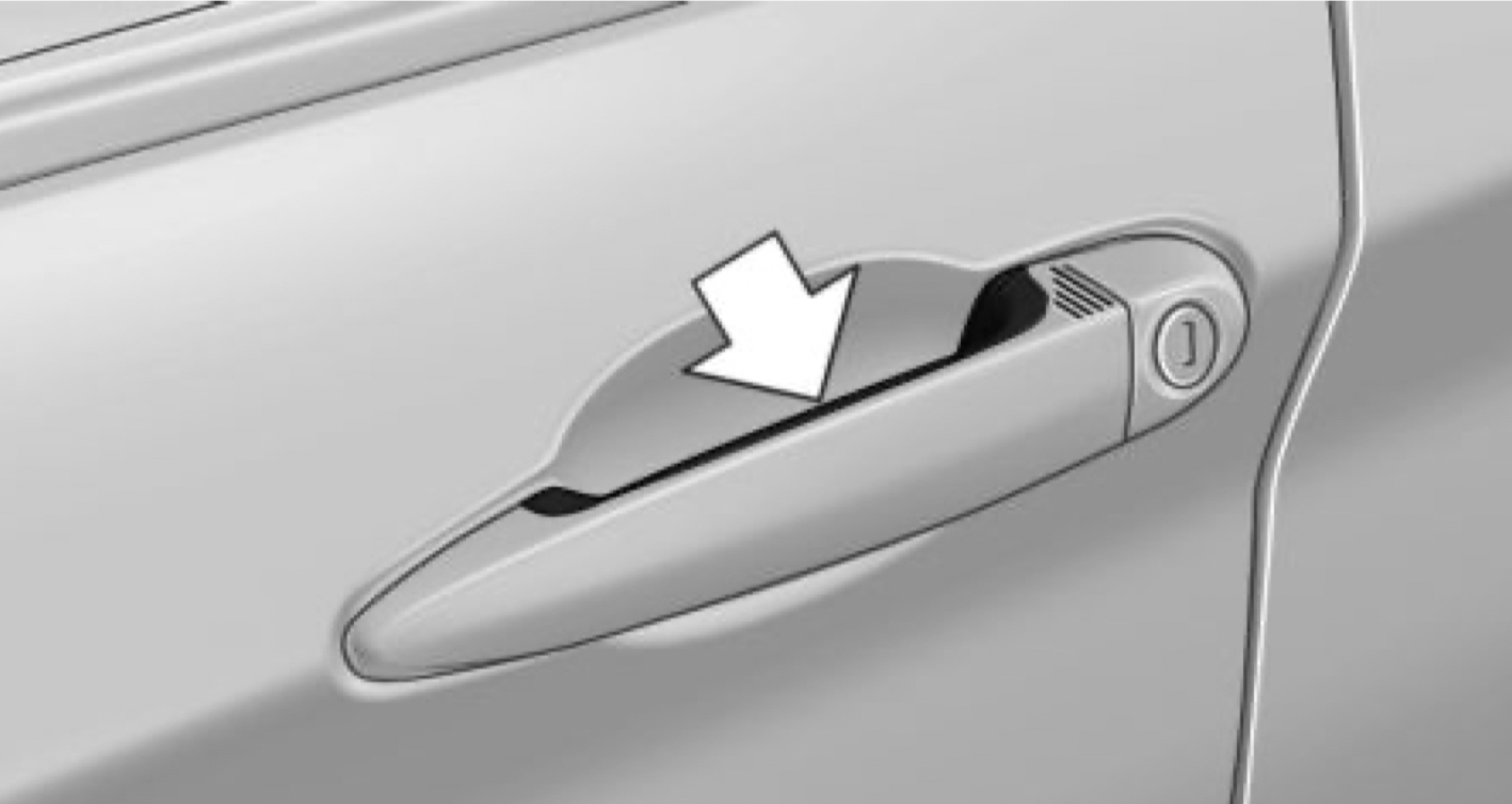
Grasp the door handle on the driver's or front passenger door completely.
Locking the vehicle
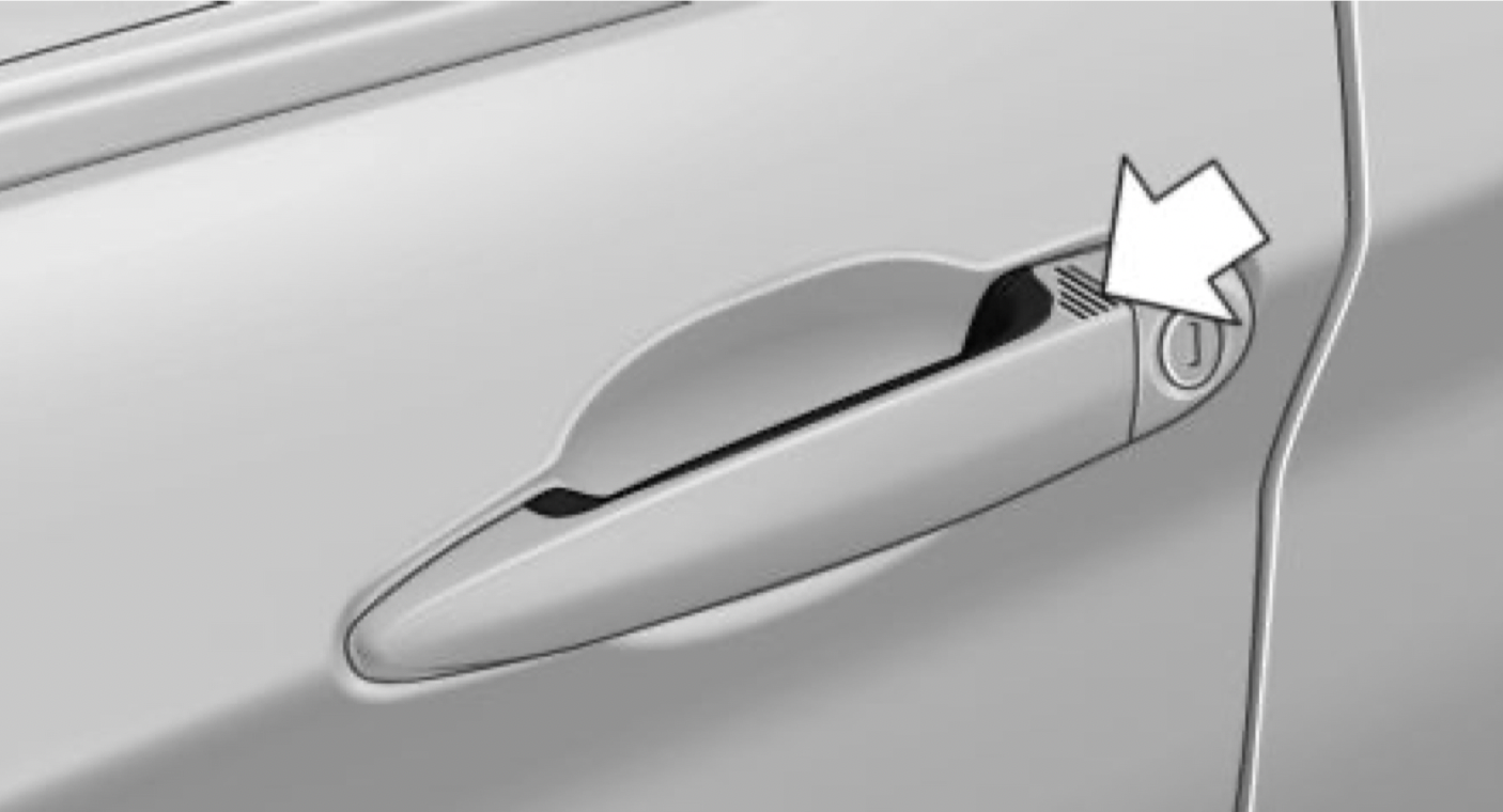
Touch the surface on the door handle of the driver's or front passenger door with your finger for approx. 1 second without grasping the door handle.
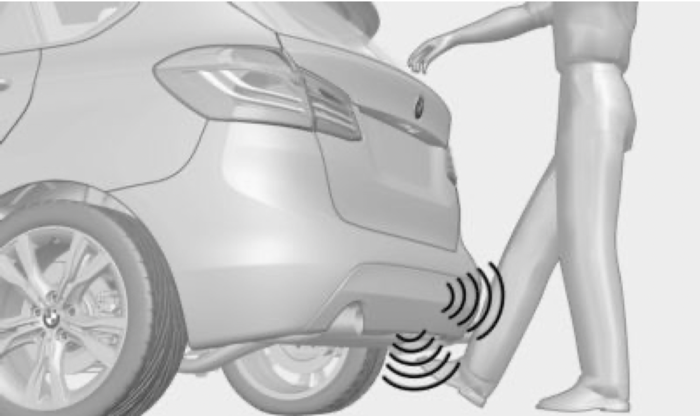
With automatic tailgate operation: opening and closing the tailgate with no-touch activation
Concept
The tailgate can be opened and closed with notouch activation using the remote control you are carrying.
Performing the foot movement
Tailgate
Opening
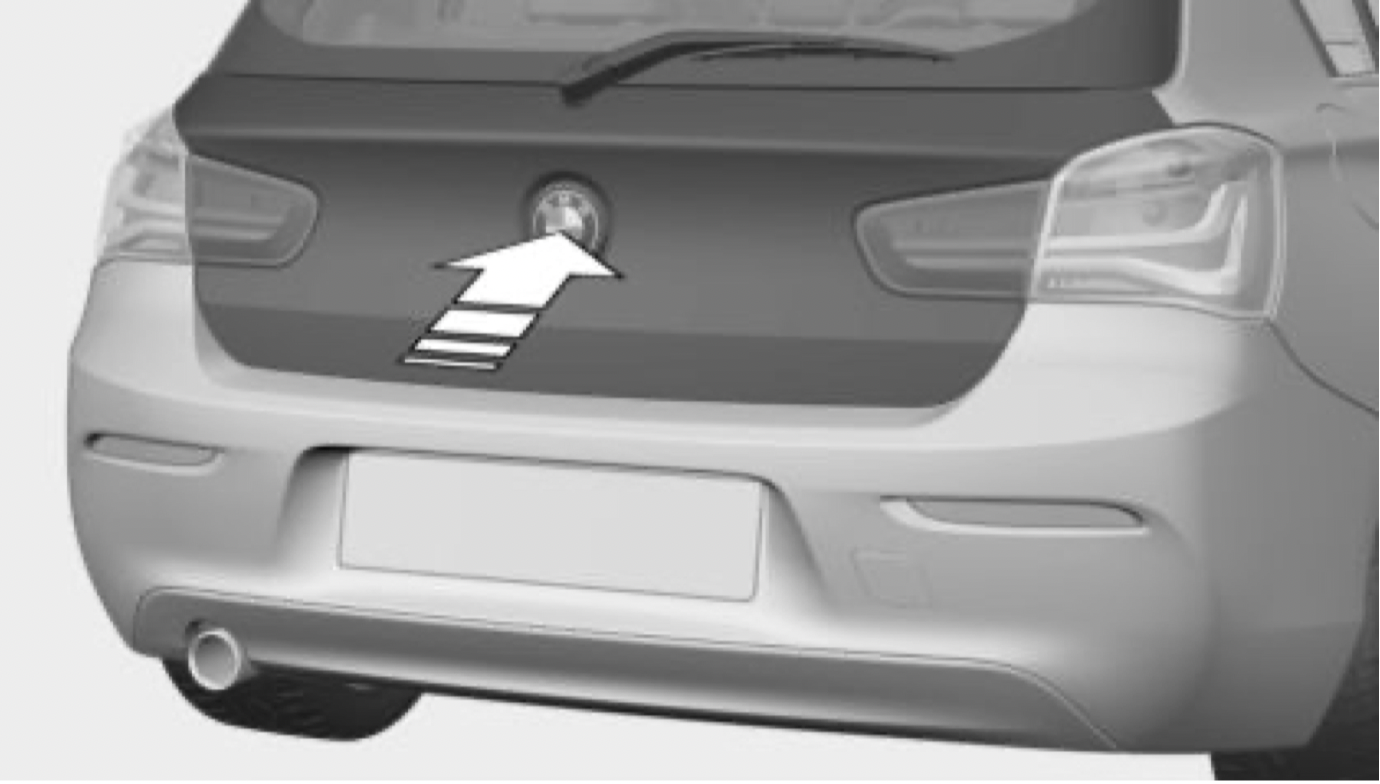
 Press button on the remote control for approx. 1 second.
Depending on the setting, the doors may also be unlocked.
Closing
Electrically adjustable seats
Adjusting the head restraint
Height
Adjusting the exterior mirrors
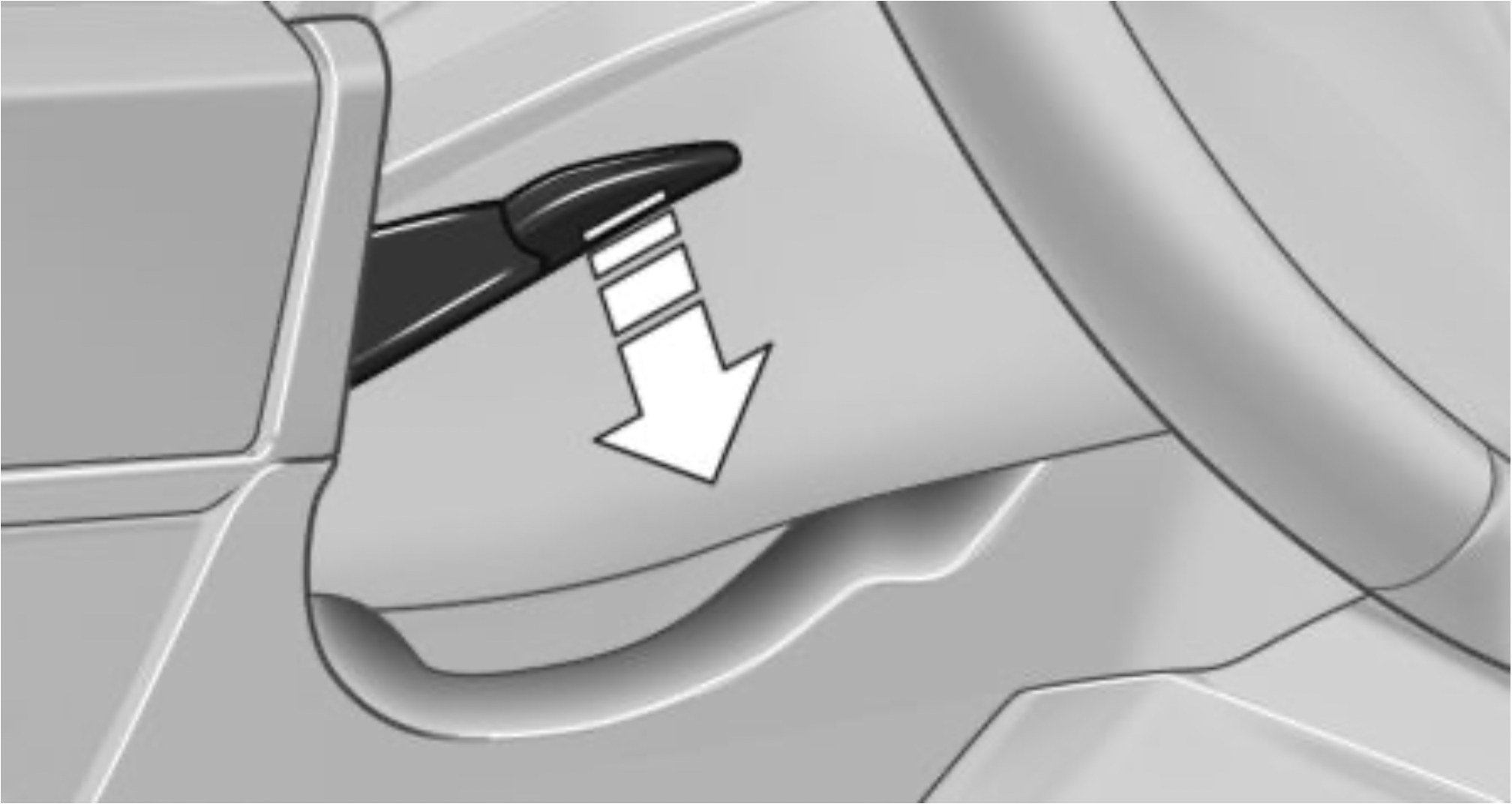
Adjusting the steering wheel
Manual steering wheel adjustment
Memory function
Concept
The following settings can be stored and, if necessary, retrieved using the memory function:
Storing
 Press button. The LED in the button lights up.
Calling up settings
The stored position is called up automatically. Press selected button 1 or 2.
The procedure stops when a switch for setting the seat or one of the memory buttons is pressed.
While driving, the seat position adjustment on the driver's side is interrupted after a short time.
In the vicinity of the steering wheel
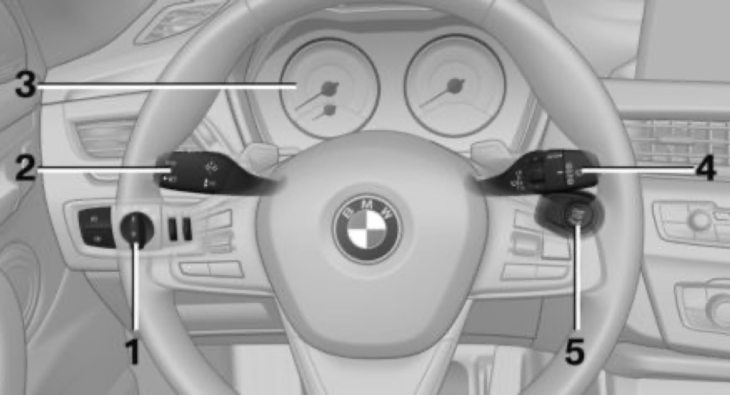
Indicator/warning lights
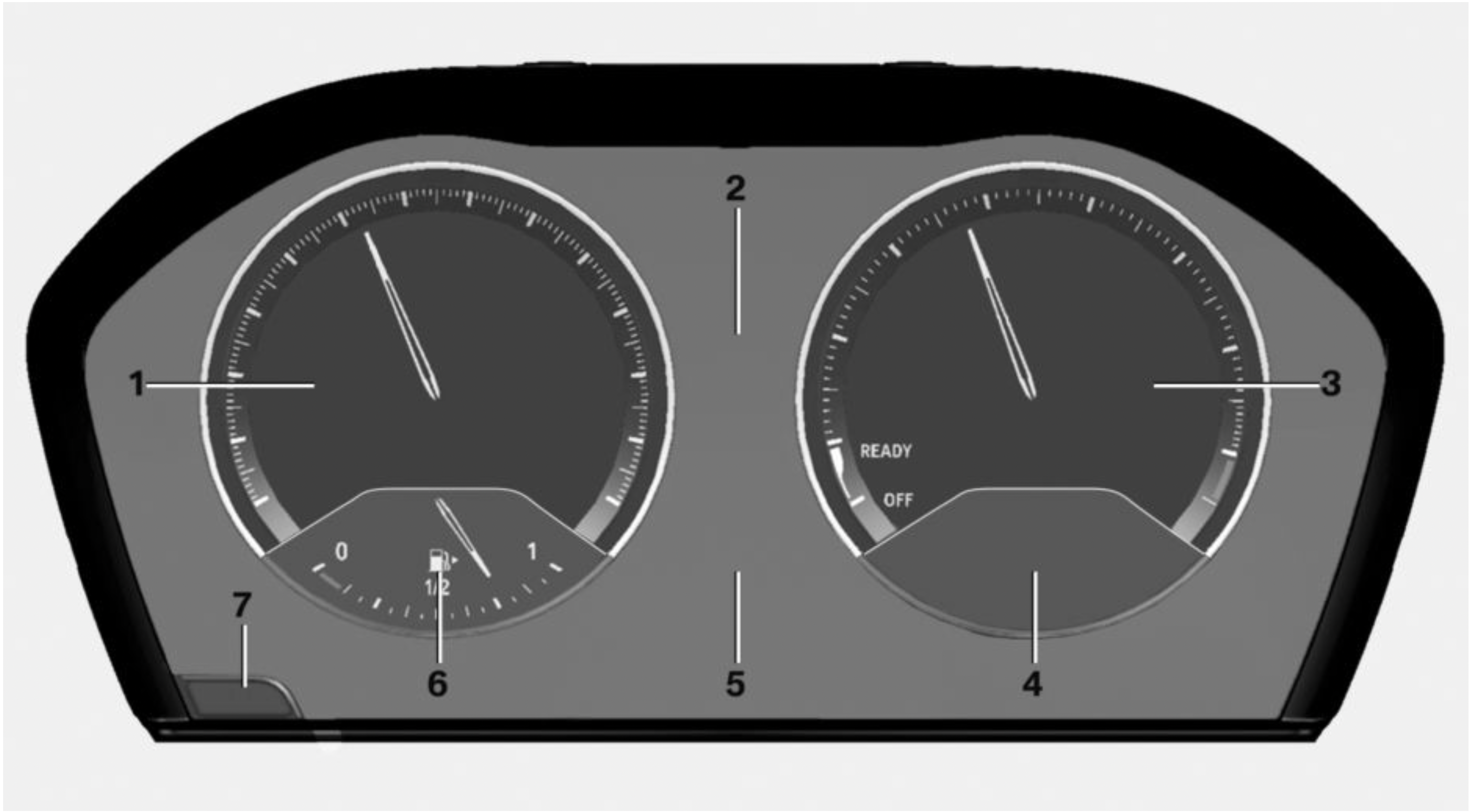
Instrument cluster
The indicator/warning lights can light up in a variety of combinations and colors.
Several of the lights are checked for proper functioning and light up temporarily when the engine is started or the ignition is switched on.
Driver's door
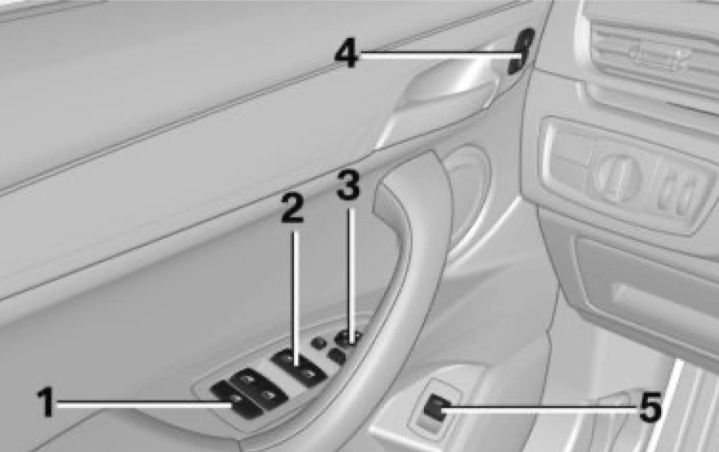
Switch console
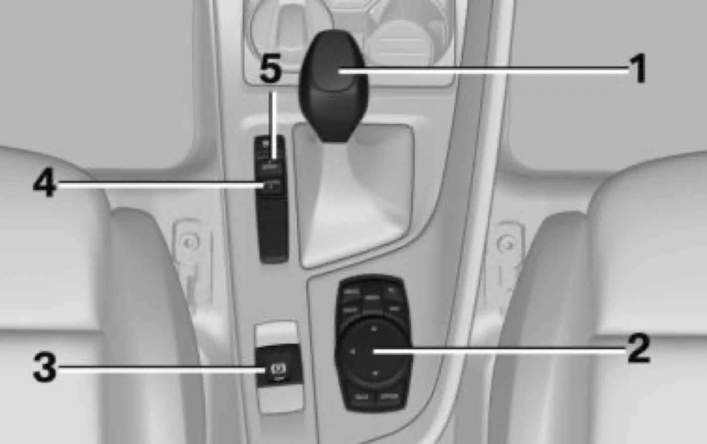
iDrive
Concept
The iDrive combines the functions of many switches. These functions can be operated via the Controller and, depending on the equipment version, the touchscreen.
Controller
General information
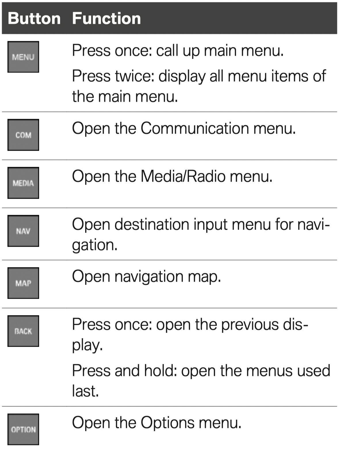
The buttons can be used to open the menus directly. The Controller can be used to select menu items and enter the settings.
Buttons on the Controller
Voice activation
Using the voice activation system
Activating the voice activation system
 Press button on the steering wheel.
 This symbol in the instrument cluster indicates that the voice activation system is active.
If no other commands are possible, operate the function via iDrive.
Terminating the voice activation system
Press the button on the steering wheel or ›Cancel‹.
Help on the voice activation system
Information on Emergency Requests
Do not use the voice activation system to initiate an Emergency Request. In stressful situations, the voice and vocal pitch can change. This can unnecessarily delay the establishment of a phone connection.
Instead, use the SOS button close to the interior mirror.
Starting and stopping the engine
Ignition on/off
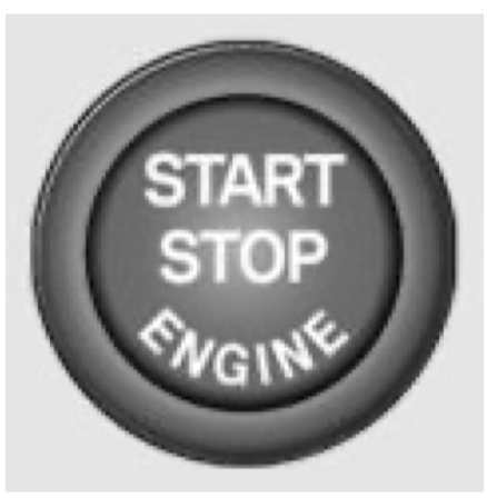
On: press the Start/Stop button.
Most of the indicator/warning lights light up for a varied length of time.
Off: press the Start/Stop button again.
All indicator lights go out.
Radio-ready state: when the ignition is switched off, press the ON/OFF button on the radio or when the engine is running, press the Start/Stop button.
Some electronic systems/power consumers remain ready for operation.
Starting/stopping the engine
Steptronic transmission: starting
Steptronic transmission: switching off
Auto Start/Stop function
Steptronic transmission: switches the engine off automatically while stationary to save fuel. The engine starts automatically when the brake pedal is released.
Parking brake
Setting
 Pull the switch.
The LED and indicator light light up.
Releasing
 With the ignition switched on:
Steptronic transmission: press the switch while the brake is pressed or selector lever position P is set.
The LED and indicator light go out.
The parking brake is released.
Steptronic transmission
Selector lever positions
Parking position P.
Reverse R.
Neutral N.
Drive mode D.
Engage selector lever position P or R only when the vehicle is stationary.
To prevent the vehicle from creeping after you select a drive mode or reverse, maintain pressure on the brake pedal until you are ready to start.
Selector lever lock
A lock prevents an inadvertent change from selector lever position P to another selector lever position and, depending on the transmission version, inadvertent switching to selector lever position P or R.
To release the lock: with the brake pedal depressed, press the button on the front or side of the selector lever.
Steptronic transmission, Sport and manual mode
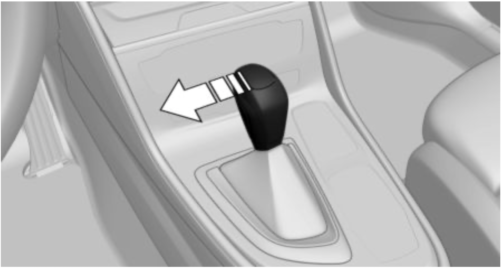
Sport program: Press the selector lever to the left out of selector lever position D.
Manual mode:
High beams, headlight flasher, turn signal, roadside parking light
High beams, headlight flasher
Push the lever forward or pull it backward.
Turn signal
Canada: roadside parking light
Illuminate the vehicle on one side.
Lights and lighting
Light functions
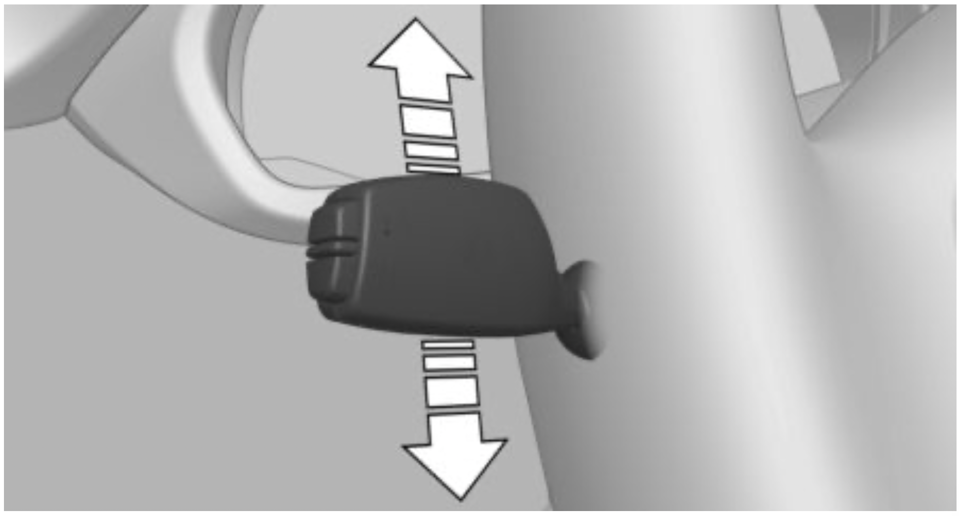
Washer/wiper system
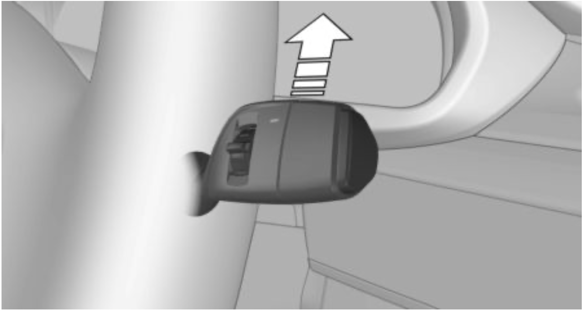
Switching the wipers on/off and brief wipe
Switching on
Press the lever up until the desired position is reached.
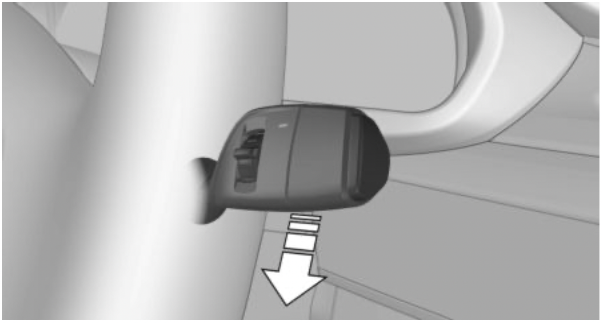
Brief wipe and switching off
Press the lever down.
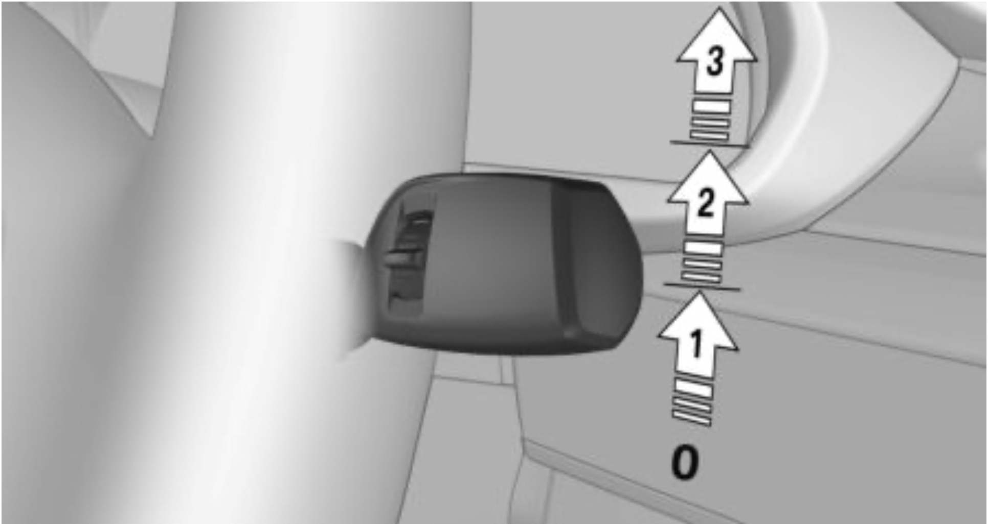
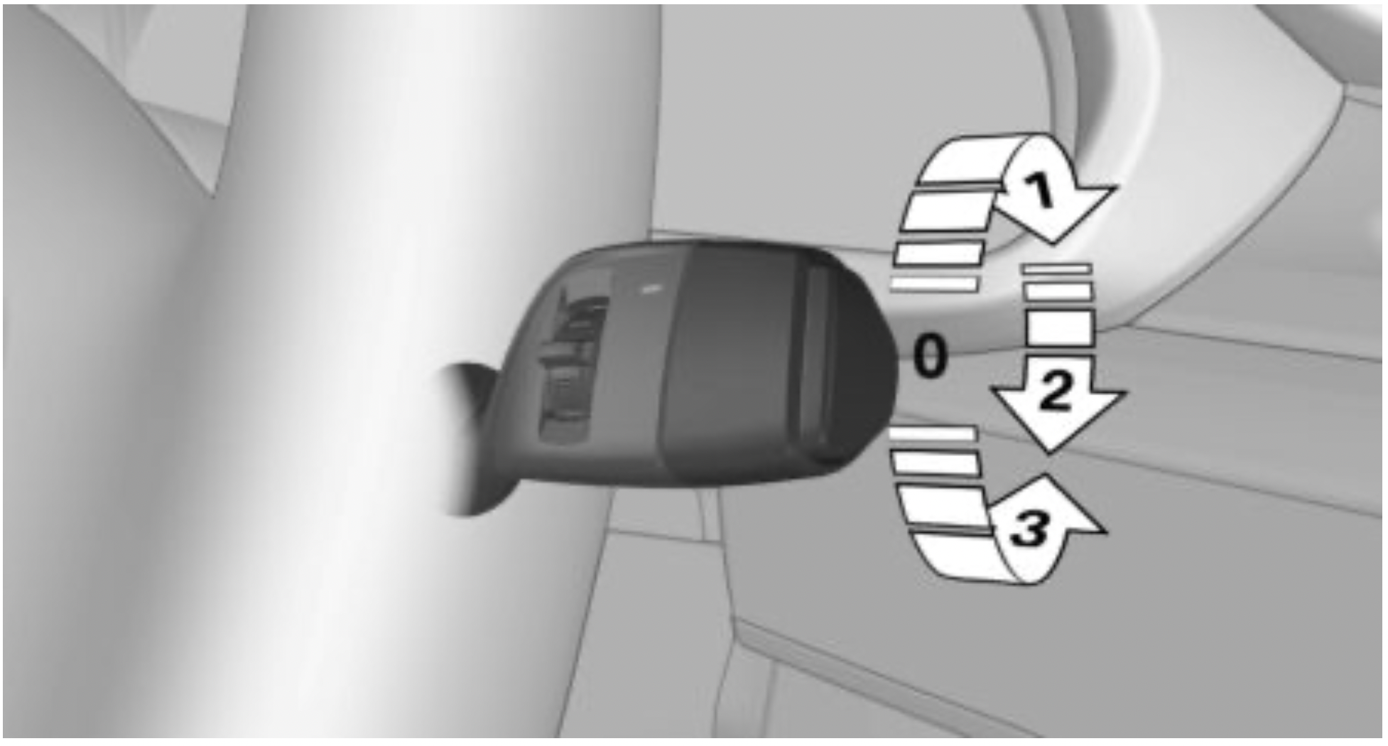
Rain sensor
Activating/deactivating
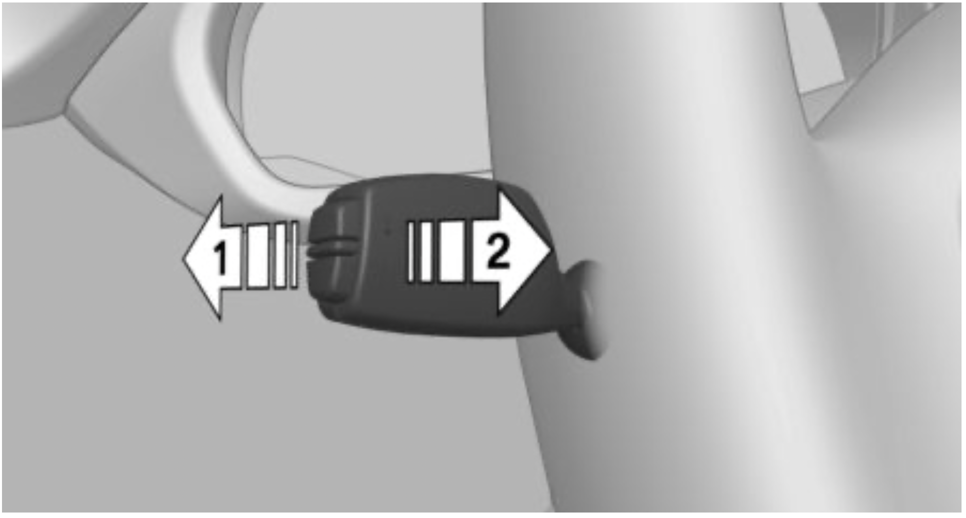
To activate: press the lever up once from its standard position, arrow 1.
To deactivate: press the lever back into the standard position.
Adjusting the sensitivity:
Turn the thumbwheel on the wiper lever.
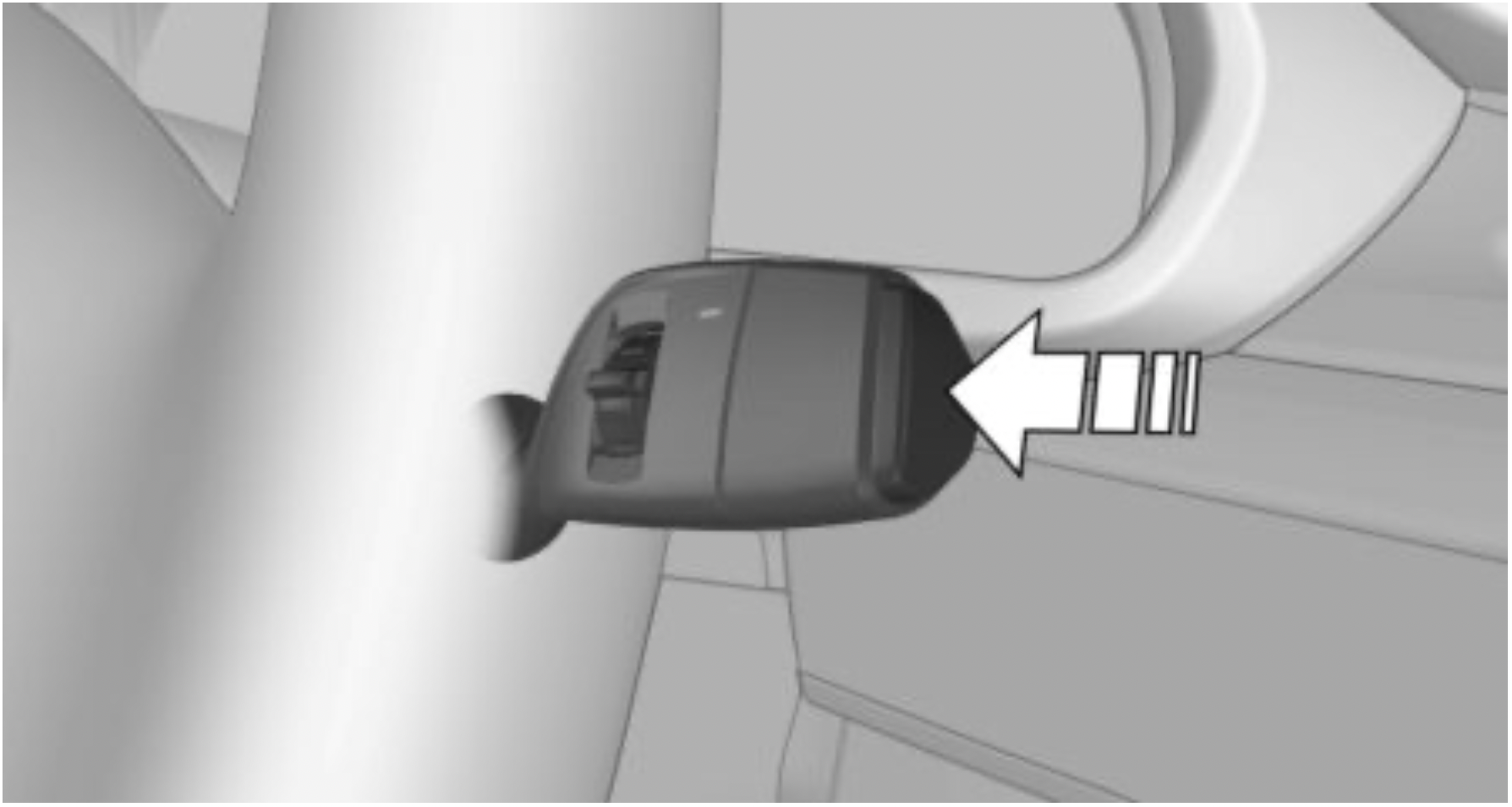
Cleaning the windshield and headlights
Rear window wiper
Switching on the rear window wiper
Turn the outer switch upward.
Clean the rear window
Turn the outer switch in the desired direction.
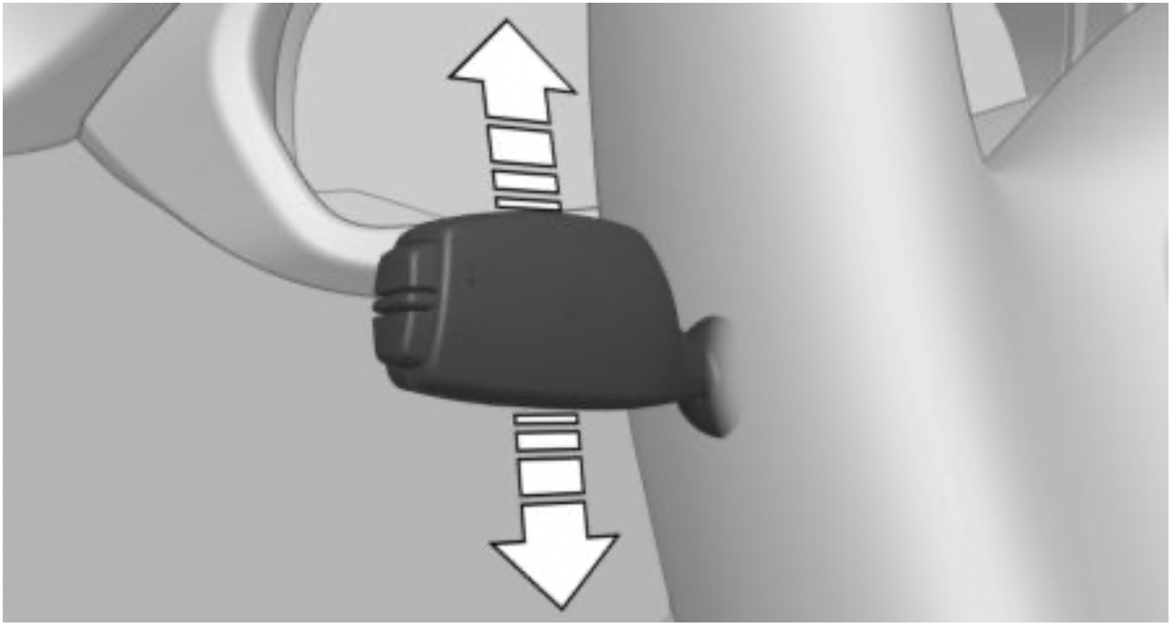
Canada: wiper system Wiper system
Switching the wipers on/off and brief wipe
Switching on
Brief wipe and switching off
Push wiper lever down.
Rain sensor
Activating/deactivating
Press button on the wiper lever.
Adjusting the sensitivity
Turn the thumbwheel on the wiper lever.
Cleaning the windshield and headlights
Pull the wiper lever towards you.
Rear window wiper
Switching on the rear window wiper
Turn the outer switch upward.
Clean the rear window
Turn the outer switch in the desired direction.
Air conditioner
Automatic climate control
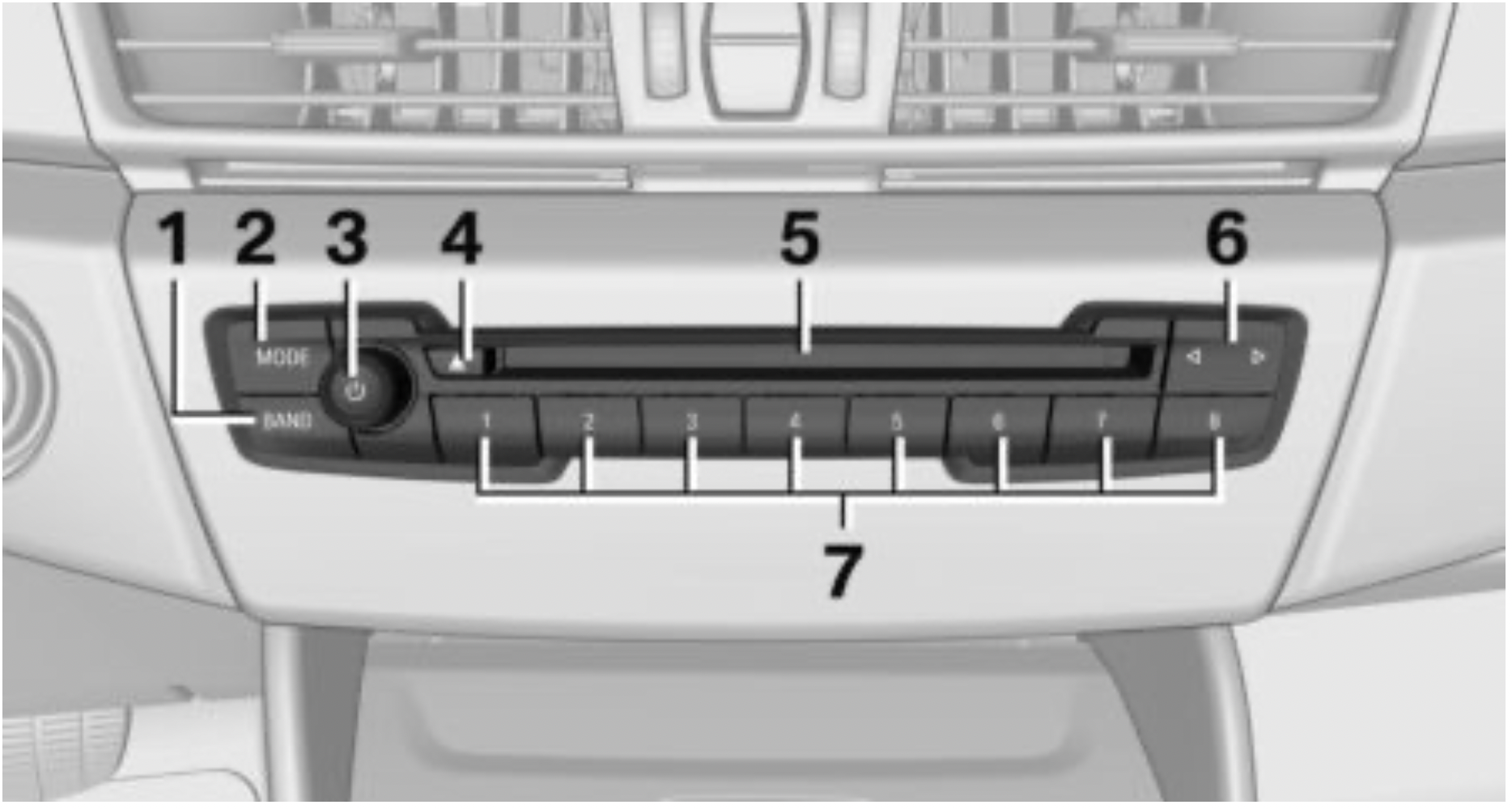
Radio
Control elements
Navigation destination entry
Entering a destination via address
State/province
 "Enter address"
Entering the address
The address can be entered in any order.
Example: entering the address via the town/city
Starting destination guidance
"Start guidance" If only the town/city was entered: destination guidance is started to the town/city center.
Connecting a mobile phone
After the mobile phone is connected once to the vehicle, the mobile phone can be operated using iDrive, the steering wheel buttons and spoken instructions.
The mobile phone is connected and will appear at the top of the list of mobile phones.
Using the phone
Accepting a call
Incoming call can be accepted via iDrive or the button on the steering wheel.
Via iDrive
 "Accept"
Via the button on the steering wheel
 Press button.
Dialing a number
 Select the symbol. The connection is established via the mobile phone to which this function has been assigned.
If connection is to be set up via the additional phone:
 Press button.
Apple CarPlay preparation
Concept
CarPlay allows certain functions of a compatible Apple iPhone to be used via Siri voice operation and iDrive.
Functional requirements
Switching on Bluetooth and CarPlay
Via iDrive:
Pairing iPhone with CarPlay
Pair iPhone via Bluetooth with the vehicle.
Select CarPlay as the function:
 "Apple CarPlay"
The iPhone is connected to the vehicle and displayed in the device list.
Refueling
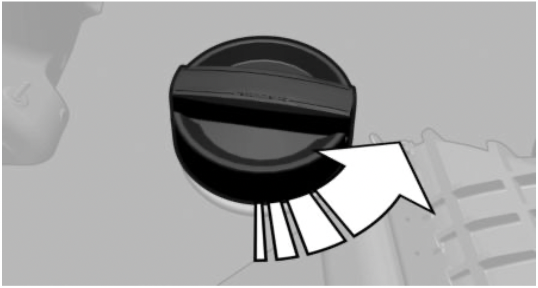
Fuel cap
Gasoline
For the best fuel efficiency, the gasoline should be sulfur-free or very low in sulfur content. Refuel only with unleaded gasoline without metallic additives.
Information on the recommended fuel grade can be found in the Owner's Manual.
Wheels and tires
Tire inflation pressure specifications
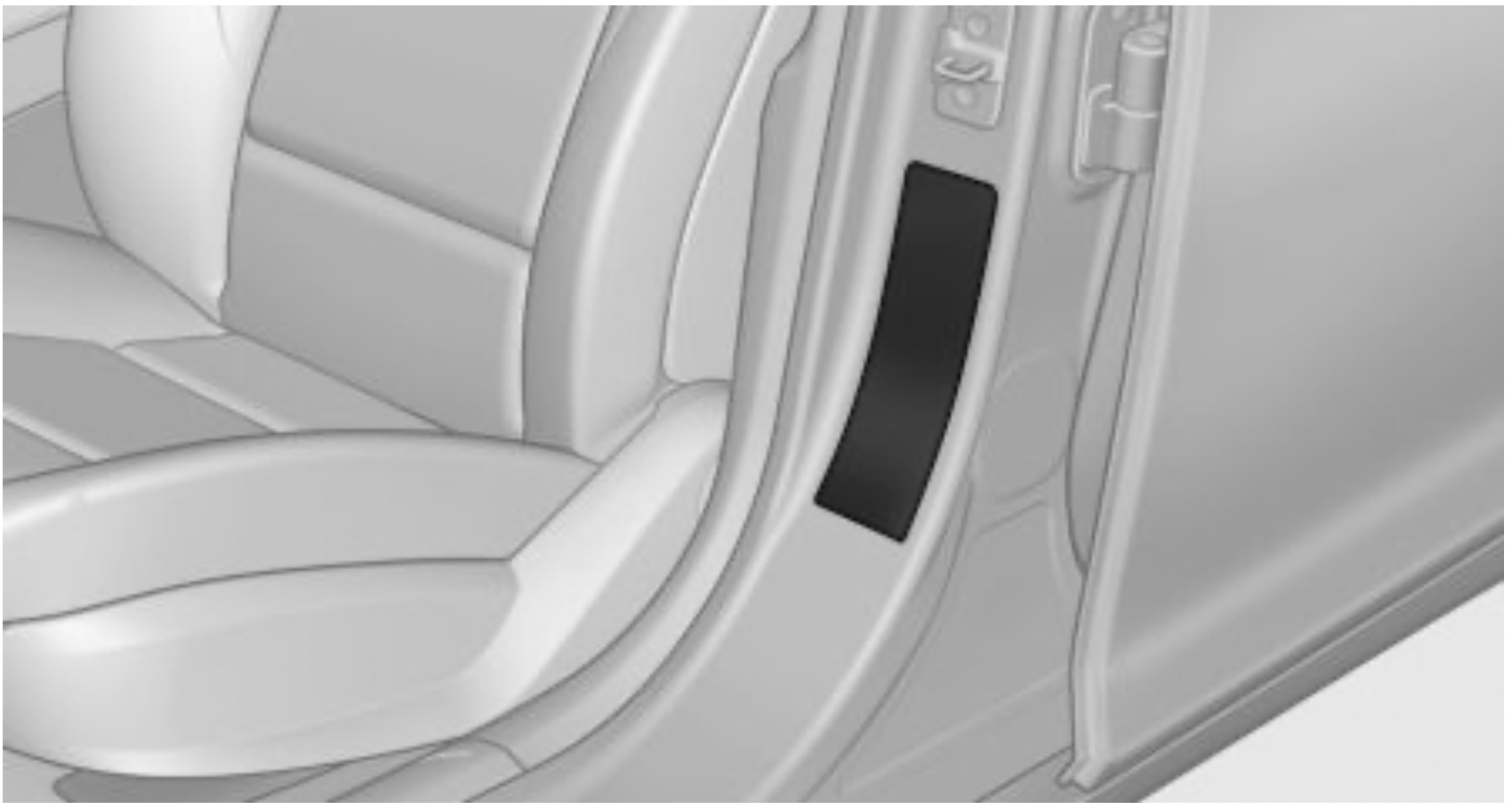
The tire inflation pressure values can be found on the sign on the door pillar.
After correcting the tire inflation pressure
Reinitialize the Flat Tire Monitor.
Reset the Tire Pressure Monitor.
Checking the tire inflation pressure
Regularly check the tire inflation pressure and correct it as needed:
Electronic oil measurement
Requirements
A current measured value is available after approx. 30 minutes of driving. During a shorter trip, the status of the last, sufficiently long trip is displayed.
Displaying the engine oil level
 "Engine oil level"
Adding engine oil
General information
Switch off the ignition and safely park the vehicle before engine oil is added.
Adding
Only add engine oil when the message is displayed in the instrument cluster.
Observe the quantity to be added in the message.
Take care not to add too much engine oil.
Observe recommended engine oil types.
Hazard warning flashers
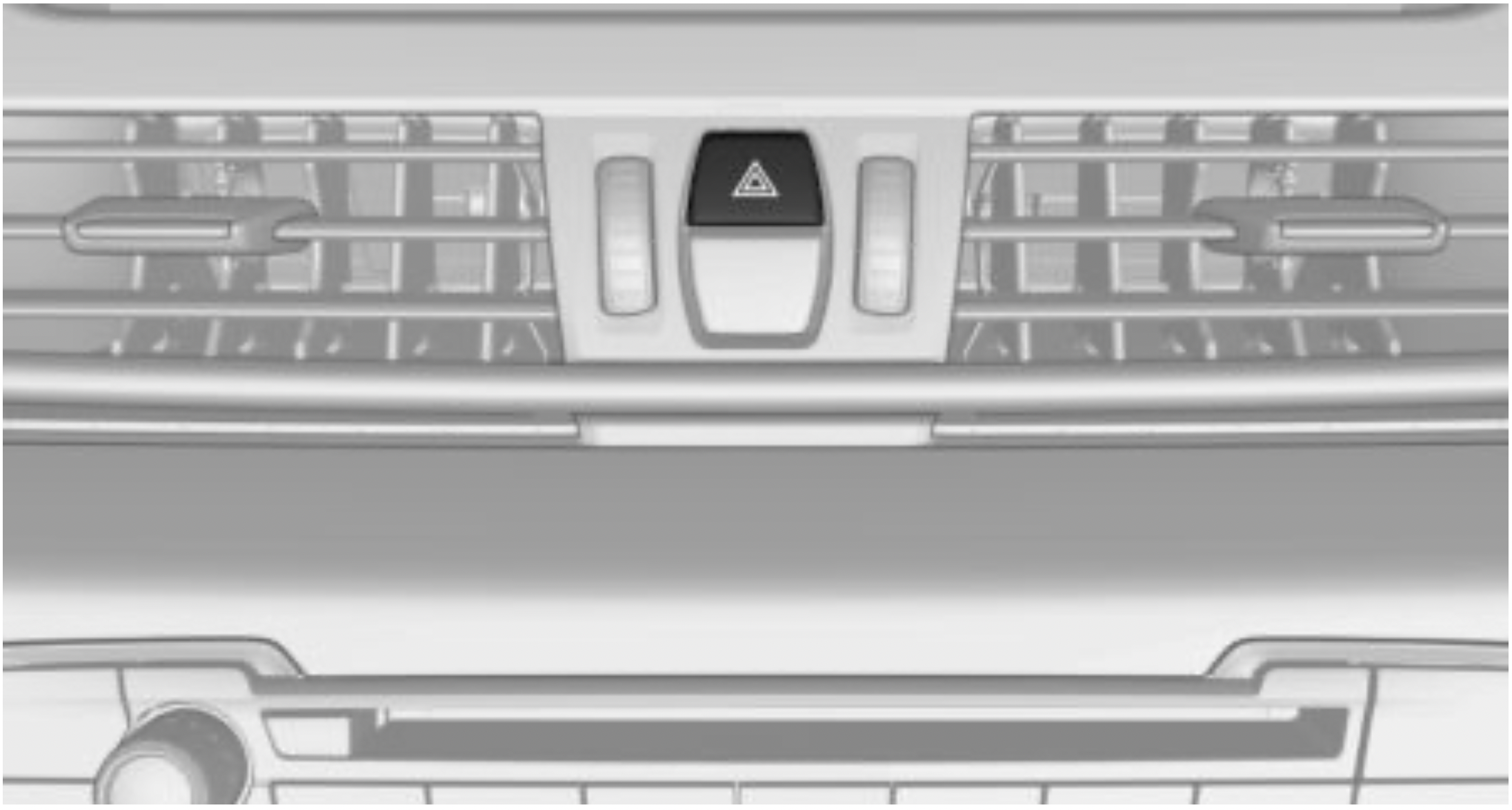
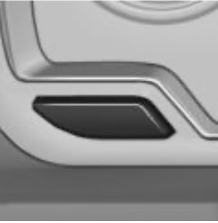
The button is located in the center console.
Breakdown assistance
Roadside Assistance
This service can be reached around the clock in many countries.
Roadside Assistance
Via iDrive:
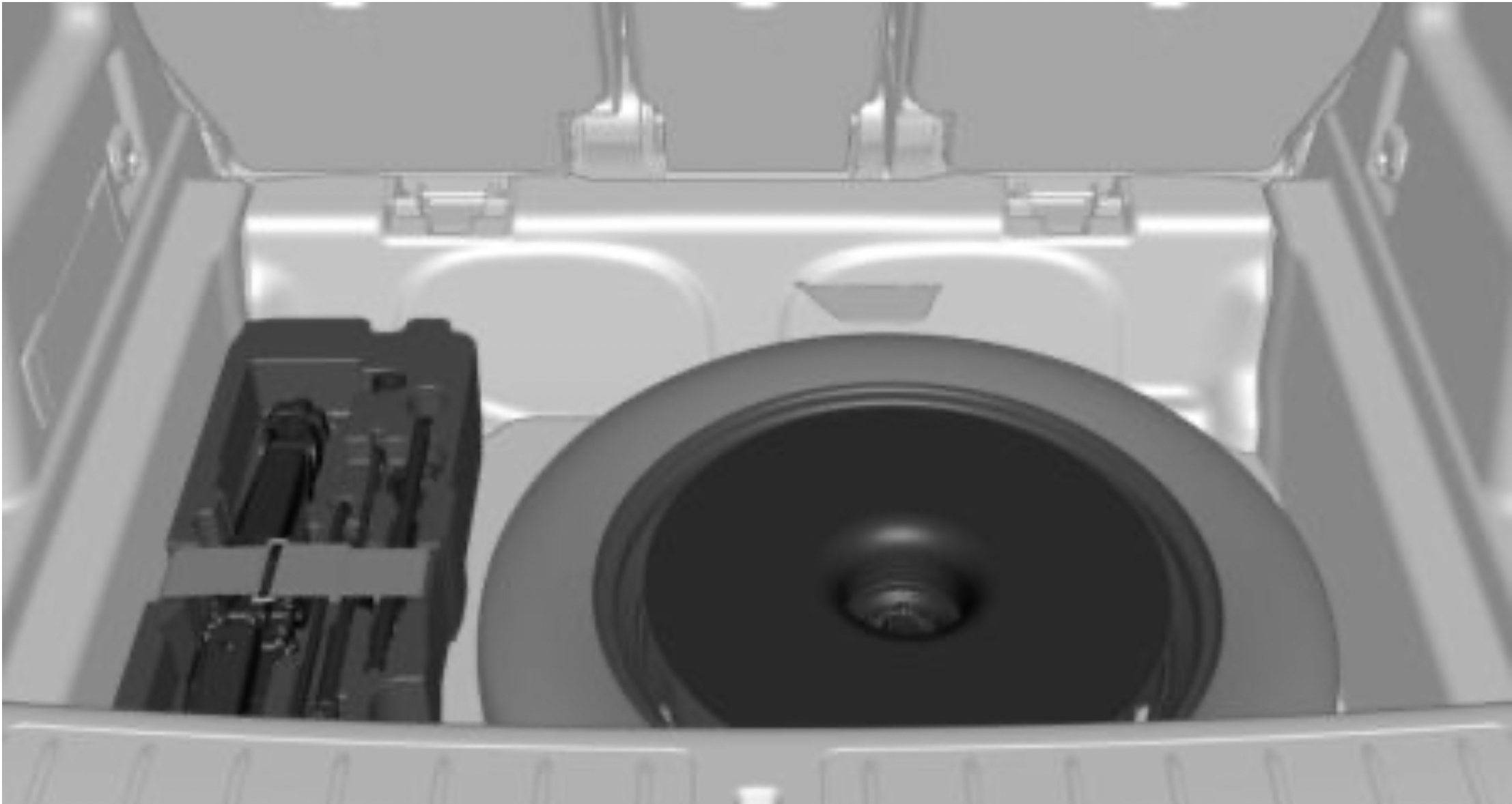
Warning triangle, first-aid kit
Warning triangle
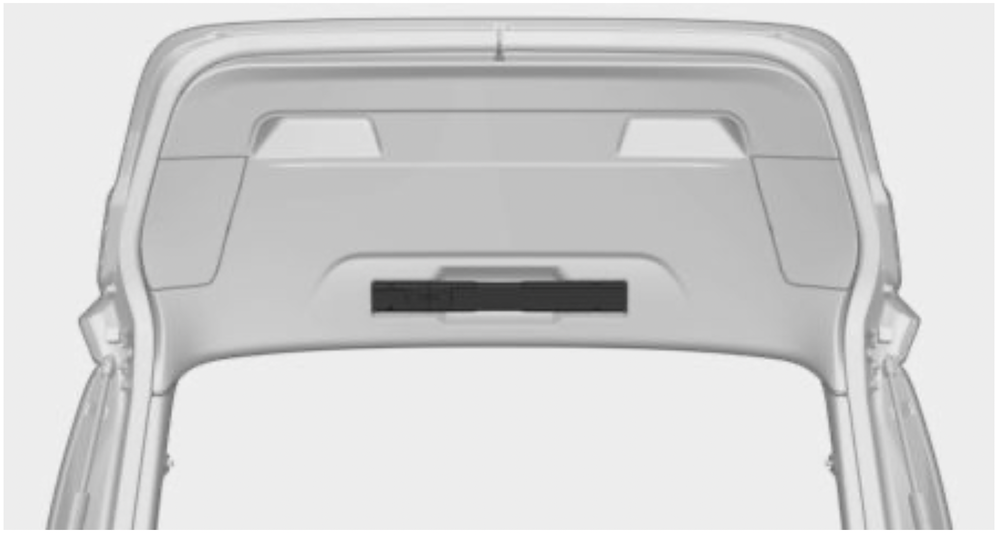
The warning triangle is located on the inside of the tailgate. Move the warning triangle sideways and remove it.
First-aid kit
The first-aid kit is located beneath the cargo floor panel.
Connected Drive
Concierge service
The BMW Assist Concierge service offers information on events, gas stations or hotels, and provides phone numbers and addresses. Many hotels can be booked directly by the BMW Concierge service. The Concierge service is part of the optional BMW Assist Response Center.
Teleservices
Teleservices are services that help to maintain vehicle mobility.
Depending on the equipment version, Teleservices comprise the following services:
This chapter describes all standard, country-specific and optional features offered with the series.
It also describes features that are not necessarily available in your vehicle, e. g., due to the selected options or country versions. This also applies to safety-related functions and systems. When using these functions and systems, the applicable laws and regulations must be observed.
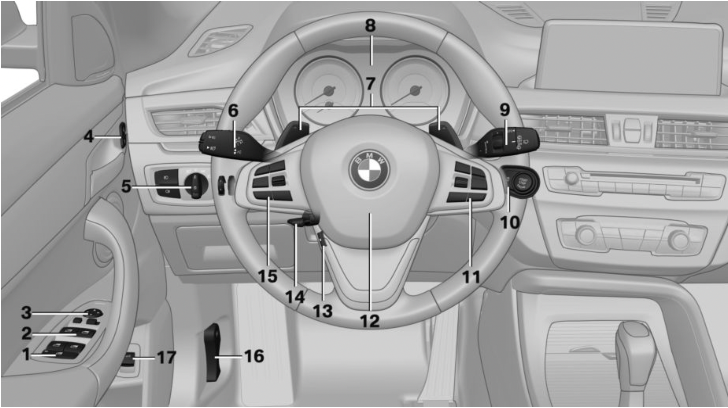
 Unlock
 Lock
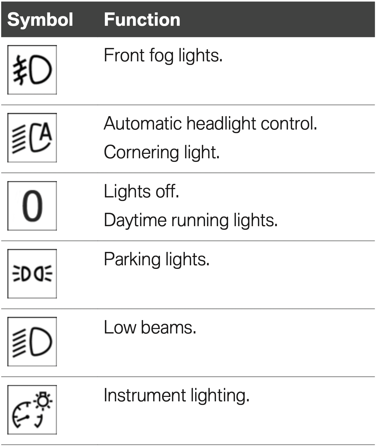
Lock Front fog lights
 Light switch
 Lights off. Daytime running lights
 Parking lights
 Low beams
 Automatic headlight control. Cornering light. High-beam Assistant
 Instrument lighting
 Turn signal
 High beams, headlight flasher
 High-beam Assistant
 Roadside parking lights
 Onboard Computer
 Wiper. Wiper on Canadian models
 Rain sensor. Rain sensor on Canadian models
 Clean the windshield and headlights
 Rear window wiper in Canadian models
 Rear window wiper
 Clean the rear window
 Start/stop the engine and switch the ignition on/off
 Auto Start/Stop function
 Entertainment source
 Volume
 Voice activation
 Telephone, see Owner's Manual for Navigation, Entertainment and Communication
 Horn, entire surface
 Heated steering wheel
 Cruise control on/off
 Active Cruise Control on/off
 Cruise control: store speed
 Pausing, continuing cruise control
 Camera-based cruise control: reduce distance
 Camera-based cruise control: increase distance
 Unlock hood
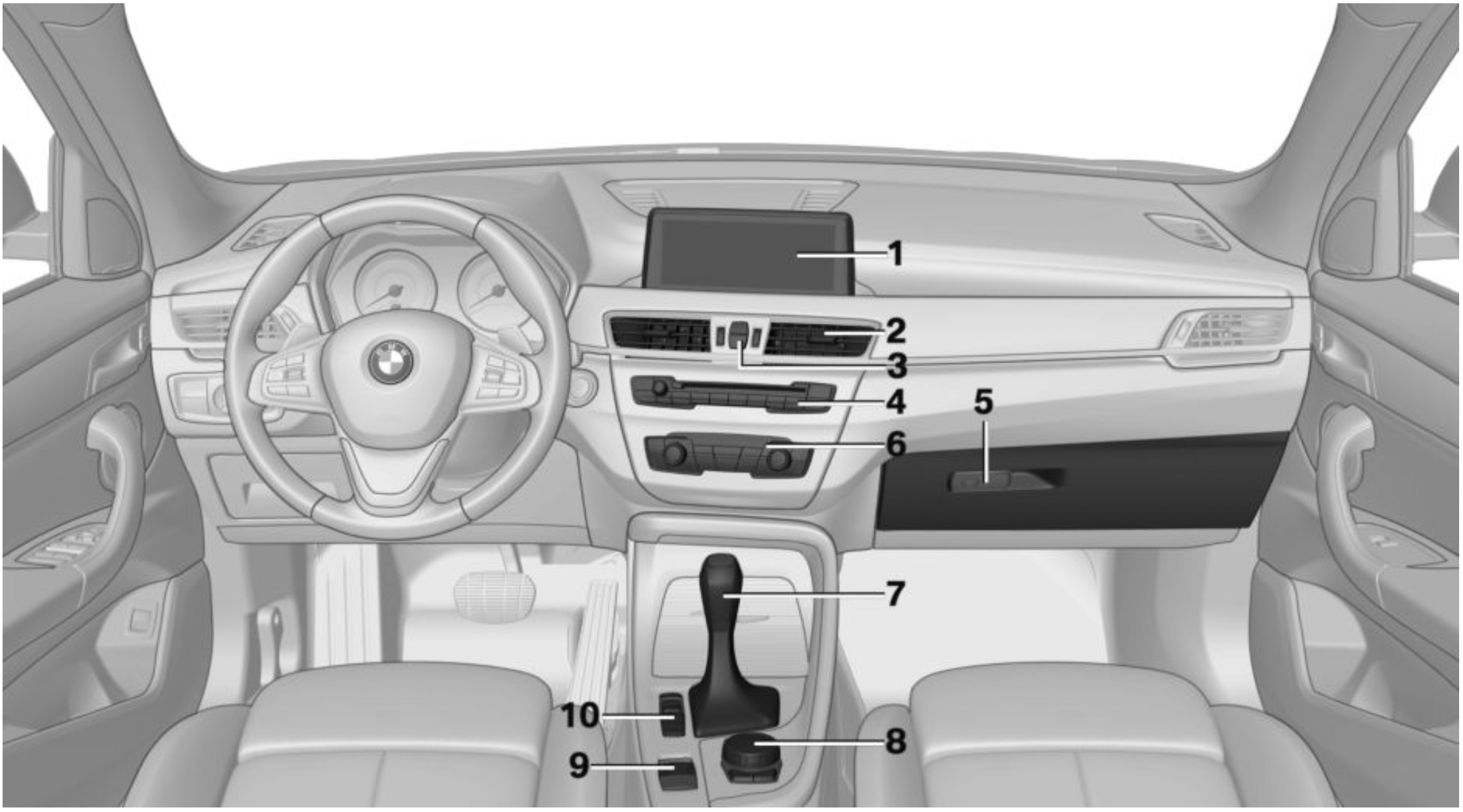
 Hazard warning system
 Intelligent Safety
 DSC Dynamic Stability Control
 Driving Dynamics Control
 PDC Park Distance Control. Rearview camera. Parking assistant
 HDC Hill Descent Control
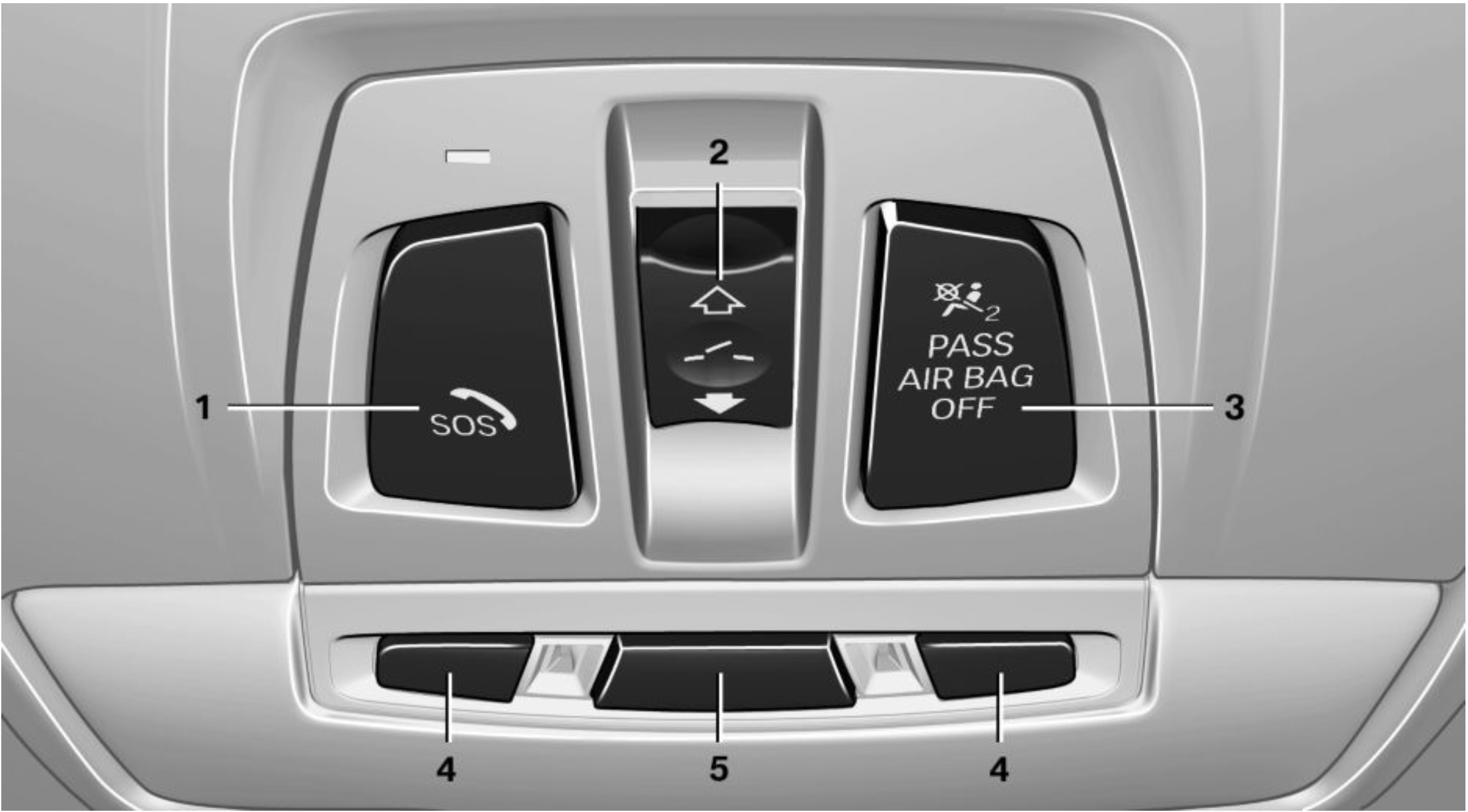
 Emergency Request, SOS
 Glass sunroof
 Indicator light, front-seat passenger airbag
 Reading lights
 Interior lights
This chapter describes all standard, country-specific and optional features offered with the series. It also describes features that are not necessarily available in your vehicle, e. g., due to the selected options or country versions. This also applies to safety-related functions and systems. When using these functions and systems, the applicable laws and regulations must be observed.
An ideal seating position that meets the needs of the occupants can make a vital contribution to relaxed, fatigue-free driving.
In the event of an accident, the correct seating position plays an important role. Additionally, follow the following chapters for safe driving:
Safety information
WARNING: Seat adjustments while driving can lead to unexpected movements of the seat. Vehicle control could be lost. There is a risk of an accident. Only adjust the seat on the driver's side when the vehicle is stationary.
WARNING: With a backrest inclined too far to the rear, the efficacy of safety gear, including safety belts can no longer be ensured. There is a risk of sliding under the safety belt in an accident. There is a risk of injuries or danger to life. Adjust the seat prior to starting the trip. Adjust the backrest so that it is in the most upright position as possible and do not adjust again while driving.
WARNING: There is a risk of jamming when moving the seats. There is a risk of injury or risk of damage to property. Make sure that the area of movement of the seat is clear prior to any adjustment.
General information
The seat setting for the driver's seat is stored for the profile currently used. When the vehicle is unlocked via the remote control, the position is automatically retrieved if the function, refer to page 85, is activated for this purpose.
The current seat position can be stored using the memory function, refer to page 98.
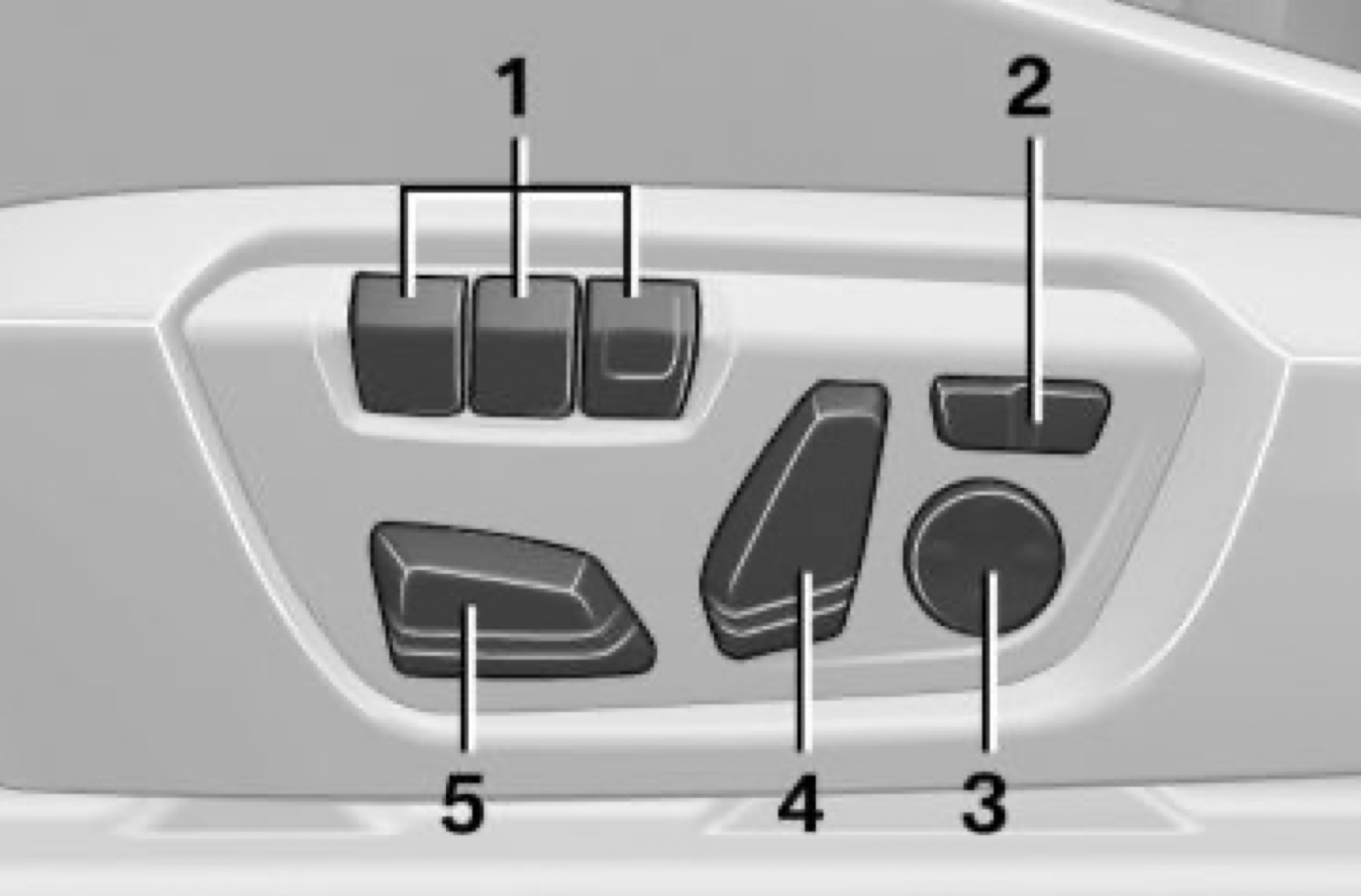
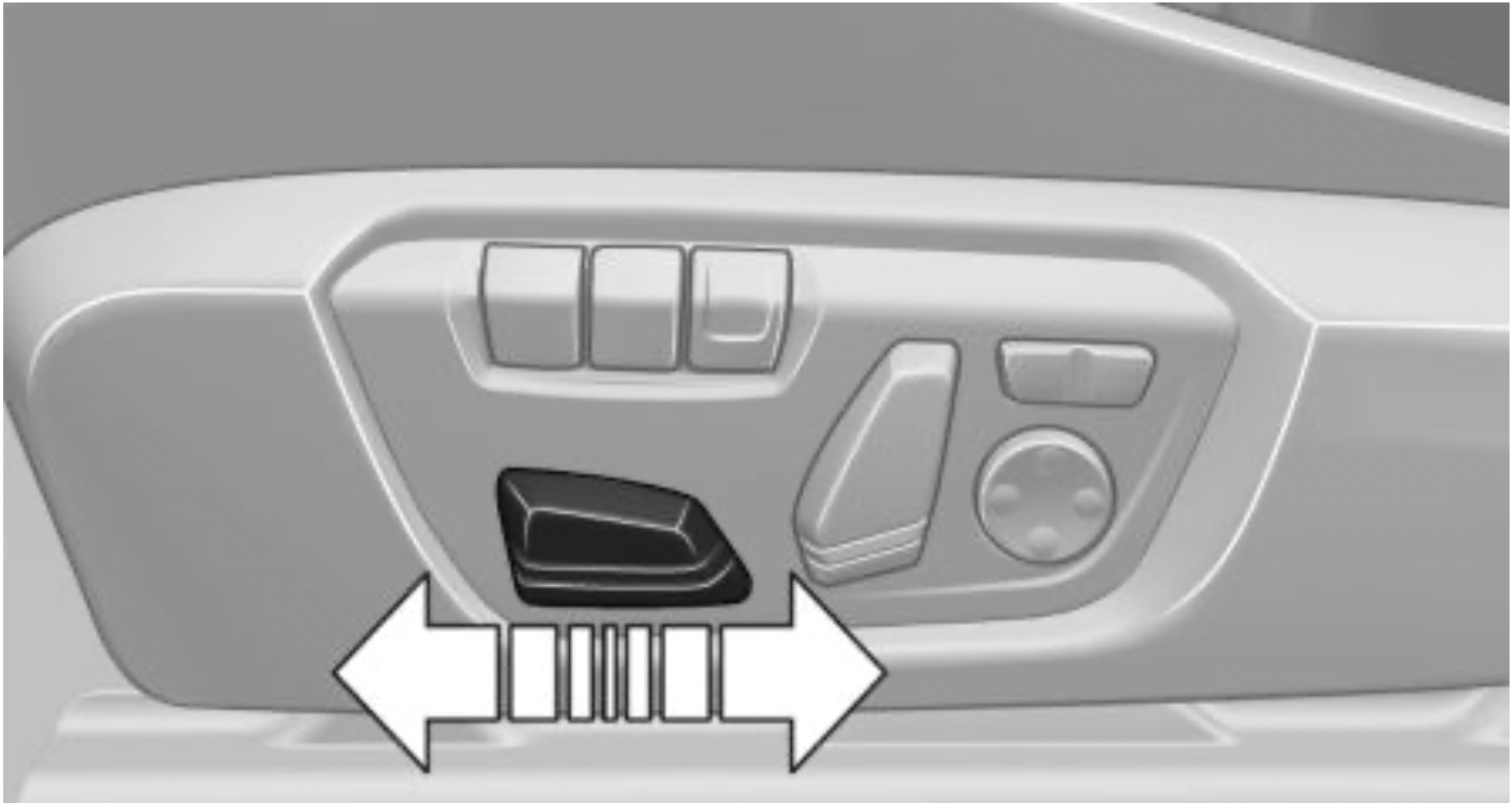
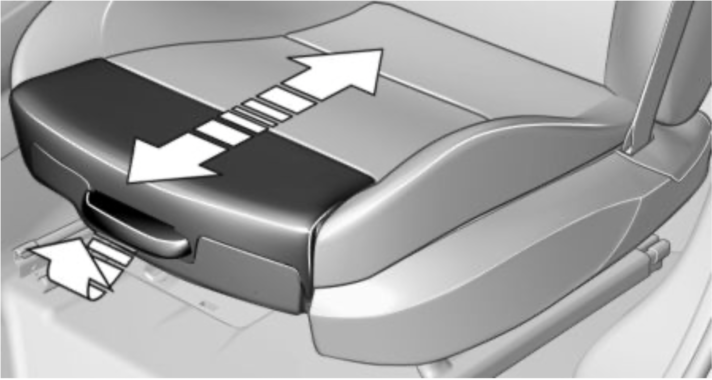
Overview
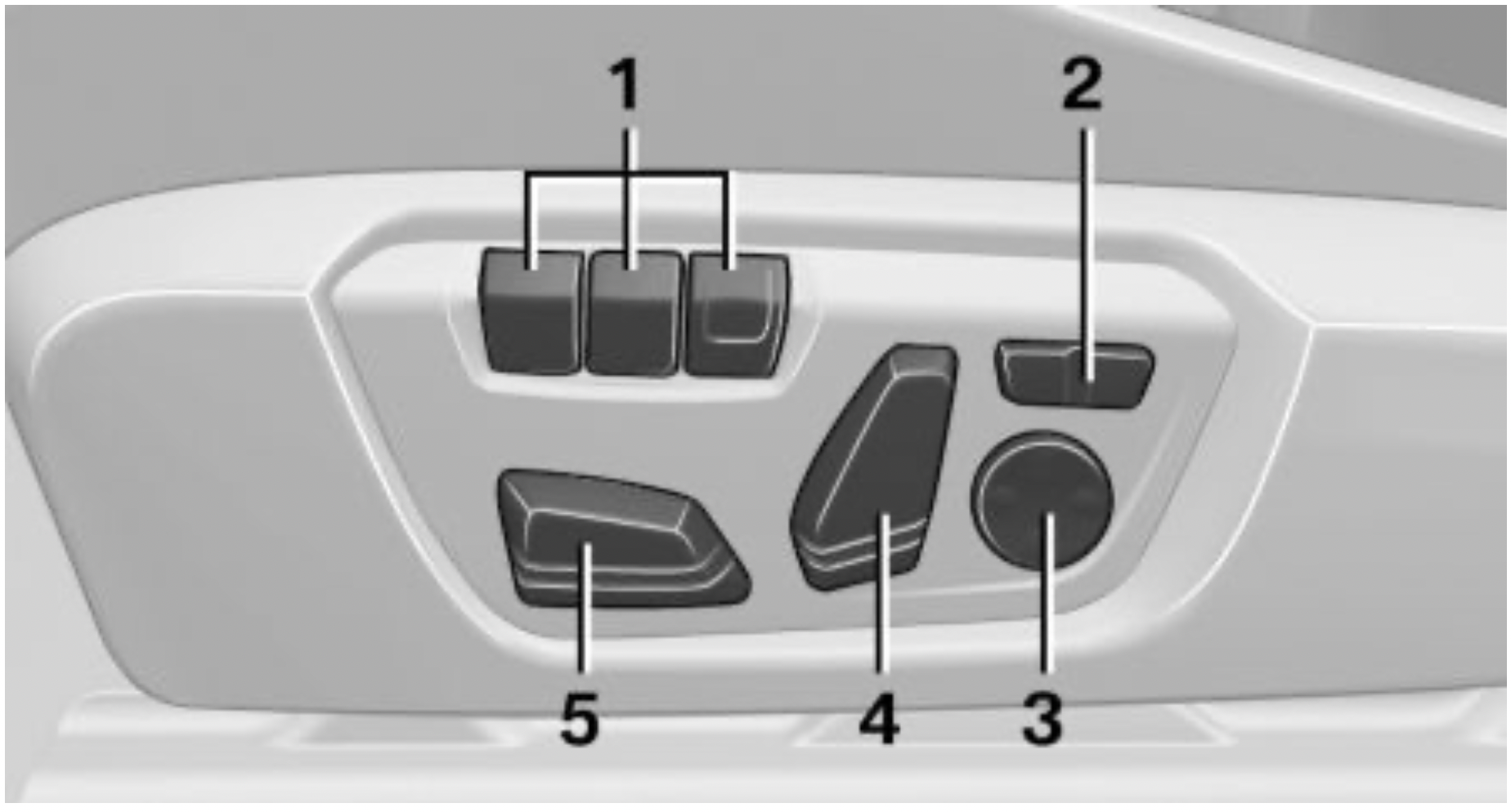
Forward/backward
Push switch forward or backward.
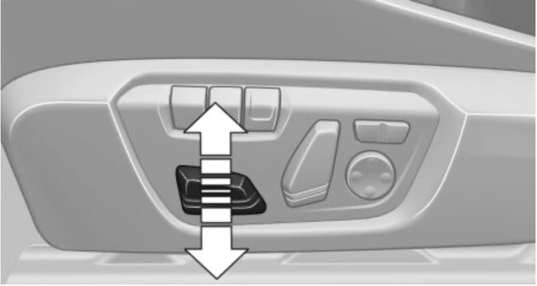
Height
Push switch up or down.
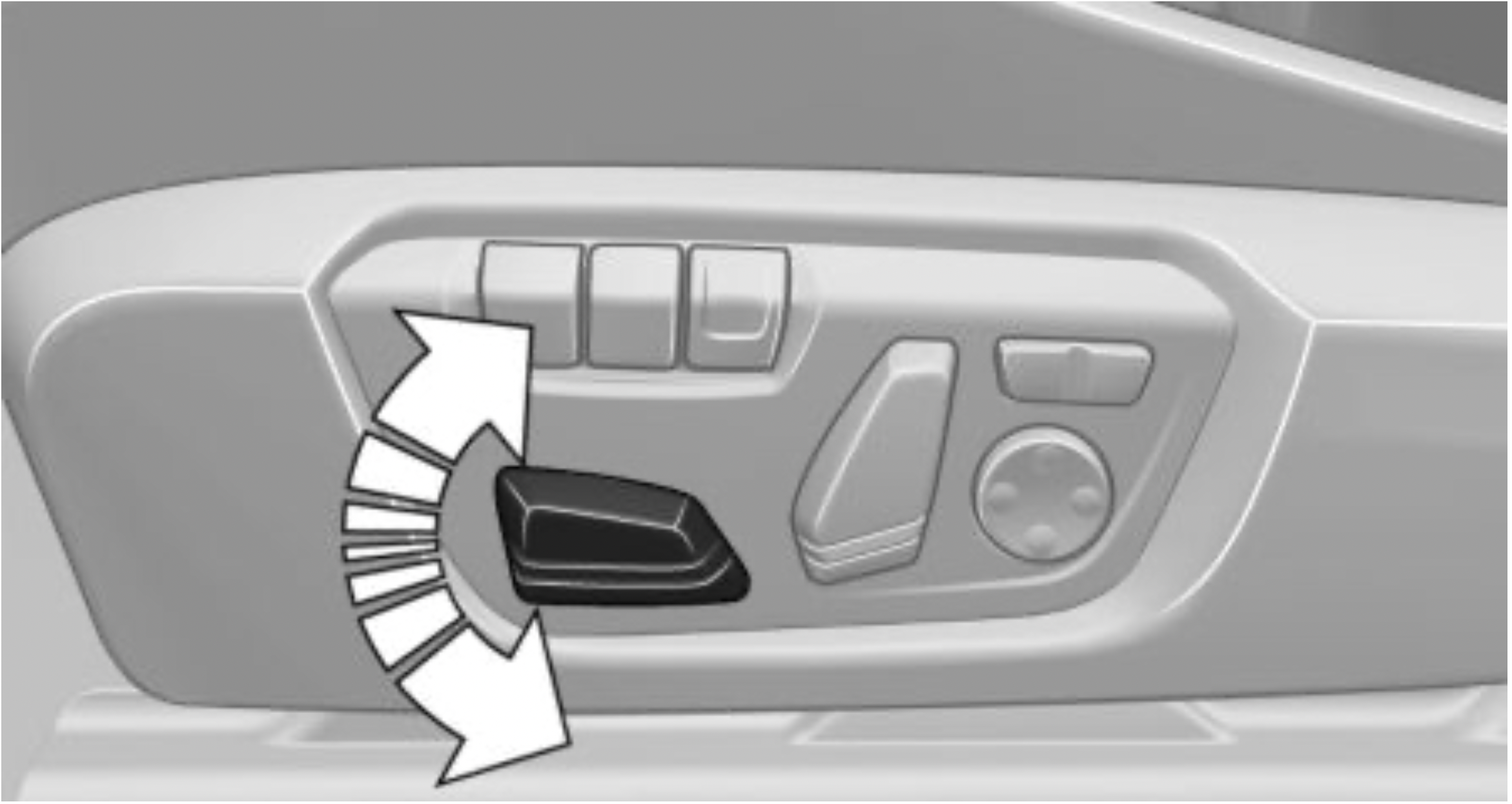
Seat tilt
Move switch up or down.
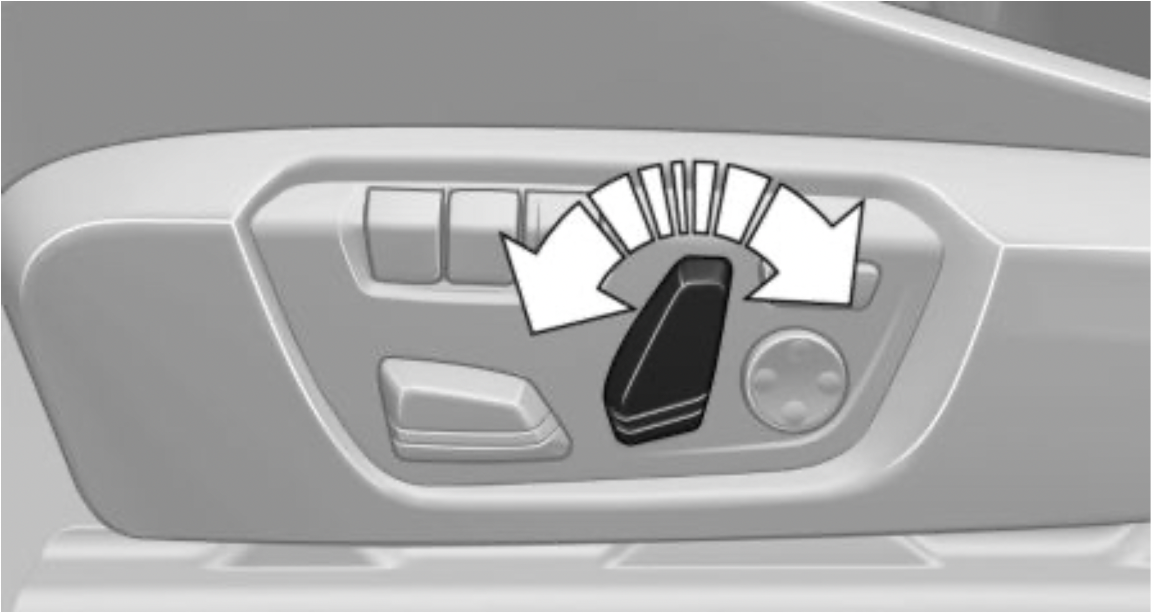
Backrest tilt
Move switch forward or backward.
Thigh support
Pull the lever at the front of the seat and adjust the thigh support.
Lumbar support
The curvature of the seat backrest can be adjusted in a way that it supports the lumbar region of the spine. The lower back and the spine are supported for upright posture.

Backrest width
Concept
Adjusting the backrest width may improve lateral support when taking corners.
General information
You can change the backrest width by adjusting the side wings of the backrest.
Settings
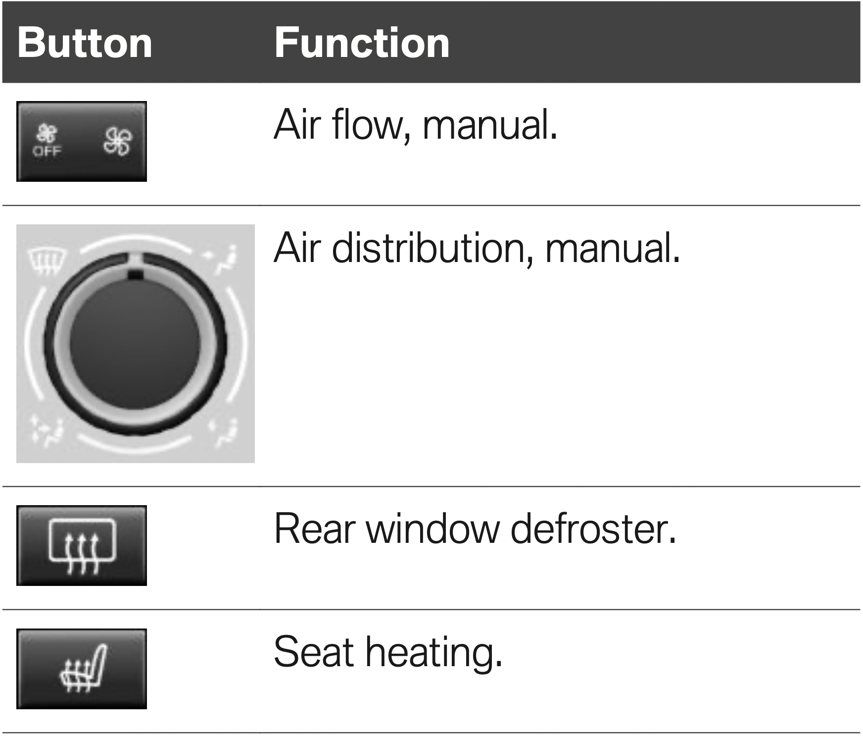
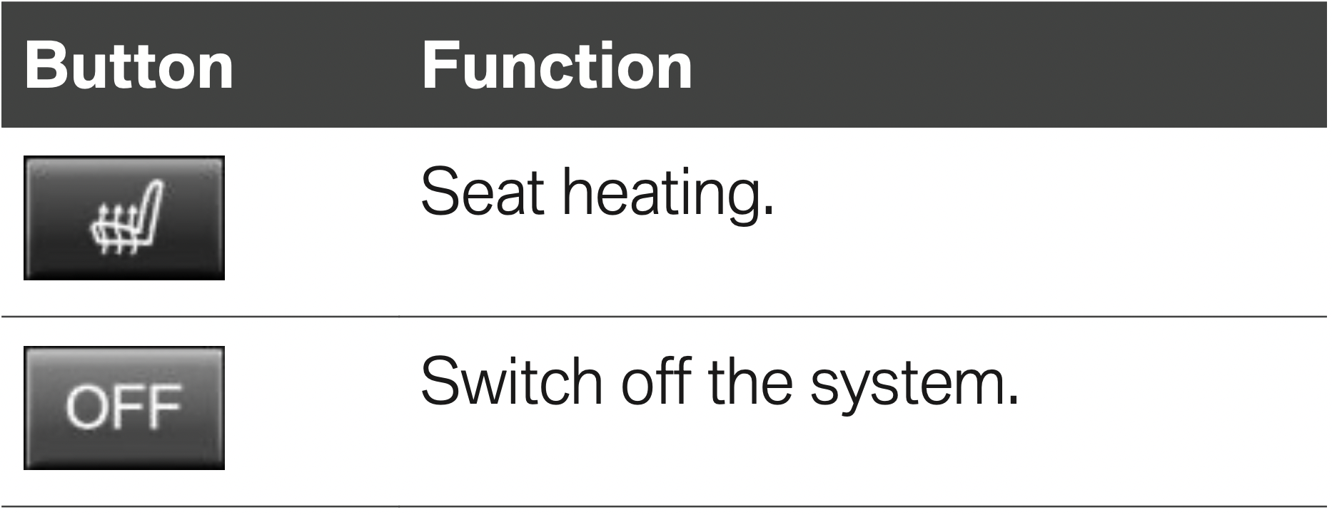
Front seat heating
Overview
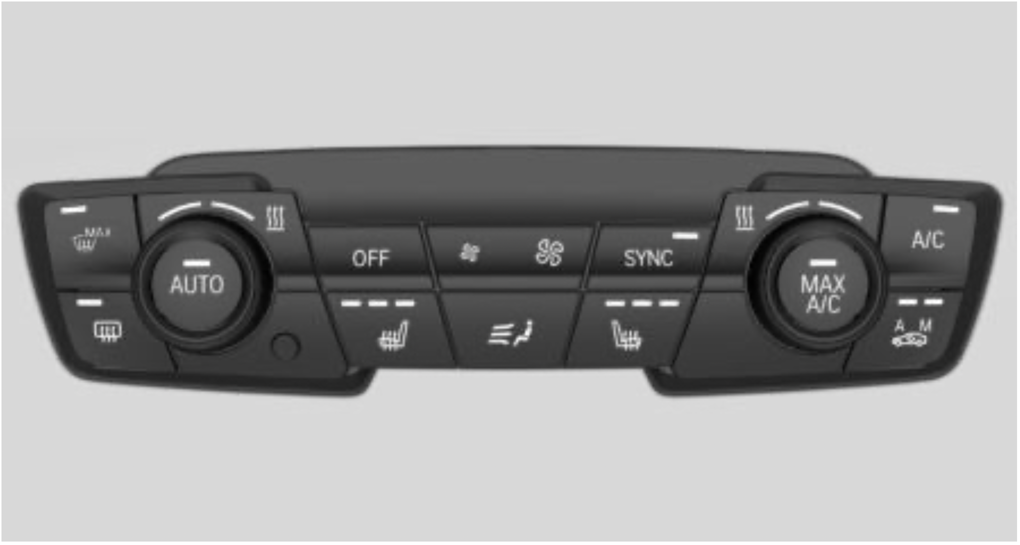
 Seat heating
Switching on
 Press button once for each temperature level.
The maximum temperature is reached when three LEDs are lit.
If the trip is continued within approx. 15 minutes after a stop, seat heating is activated automatically with the temperature selected last.
When ECO PRO is activated, refer to page 232, the heater output is reduced.
Switching off
 Press and hold the button, until the LEDs go out.
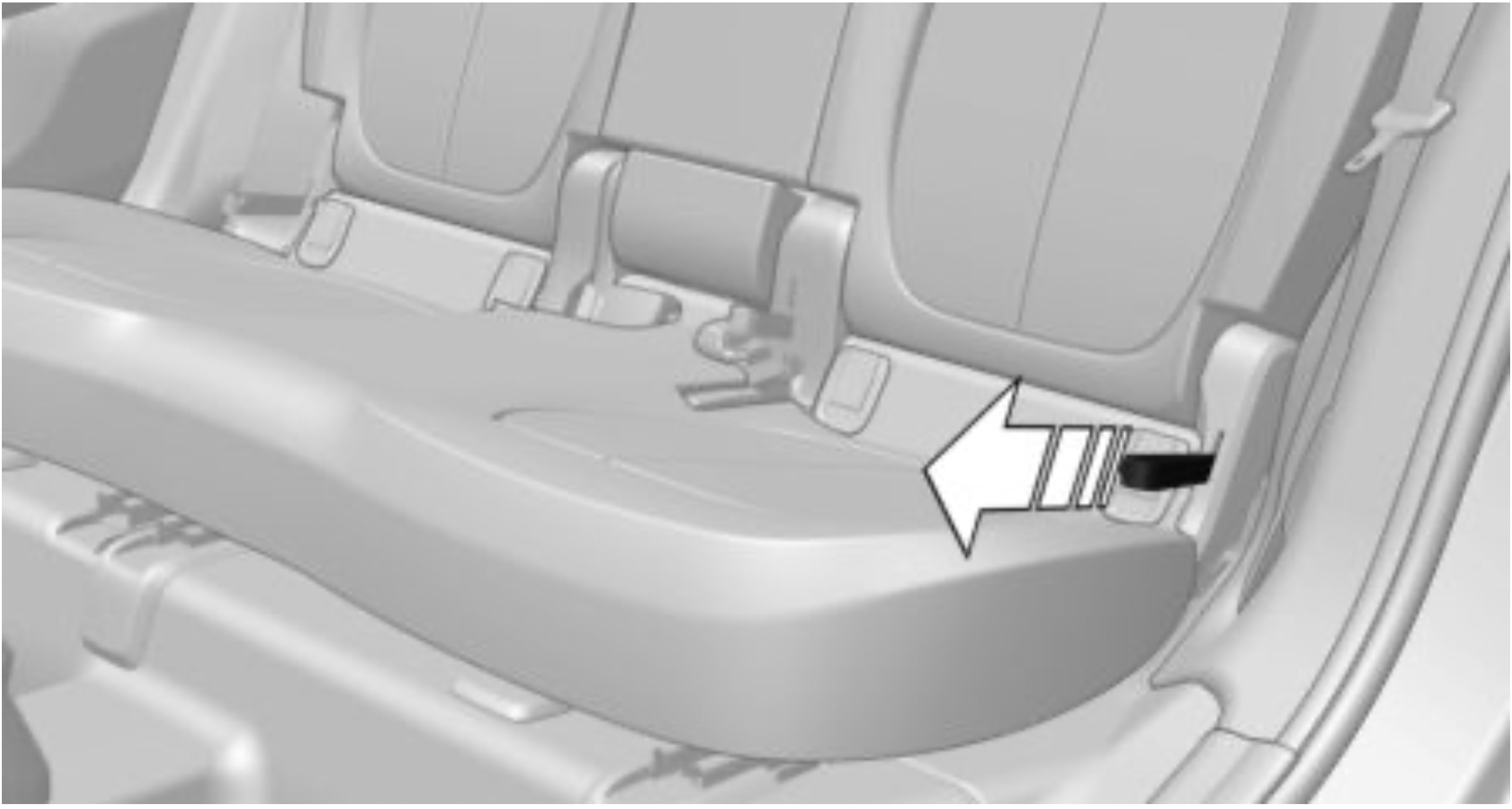
Second row of seats
Safety information
WARNING: There is a risk of jamming when folding down the center armrest in the rear. There is a risk of injury. Make sure that the area of movement of the center armrest is clear during folding down.
WARNING: Unexpected movements of the backrest while driving may occur due to unintentional unlocking of the rear backrests by the straps. There is a risk of injury. Do not fasten any objects to the straps for unlocking the rear backrests.
Backrest tilt
Pull the strap and apply your weight to the backrest or lift it off, as necessary.
Number of safety belts and safety belt buckles
The vehicle is fitted with five safety belts to ensure occupant safety. However, they can only offer protection when adjusted correctly.
The two outer safety belt buckles of the rear seat are intended for the persons sitting on the left and right.
The center safety belt buckles of the rear seat are intended for the persons sitting in the middle.
General information
Always make sure that safety belts are being worn by all occupants before driving off. Although airbags enhance safety by providing added protection, they are not a substitute for safety belts.
The upper shoulder strap's anchorage point will be correct for adult seat occupants of every build if the seat is correctly adjusted.
Safety information
WARNING: Use of a safety belt to buckle more than one person will potentially defeat the ability of the safety belt to serve its protective function. There is a risk of injuries or danger to life. Do not allow more than one person to wear a single safety belt. Infants and children are not allowed on an occupant's lap, but must be transported and secured in designated child restraint systems.
WARNING: The efficacy of safety gear, including safety belts, can be limited or lost when safety belts are fastened incorrectly. An incorrectly fastened safety belt can cause additional injuries, for instance in the event of an accident or during braking and evasive maneuvers. There is a risk of injuries or danger to life. Make sure that all occupants are wearing safety belts correctly.
WARNING: With a rear backrest that is not locked, the protective function of the middle safety belt is not guaranteed. There is a risk of injuries or danger to life. If you are using the middle safety belt, lock the wider rear seat backrest.
WARNING: The efficacy of safety gear, including safety belts, may not be fully functional or fail in the following situations:
Correct use of safety belts
Buckling the safety belt
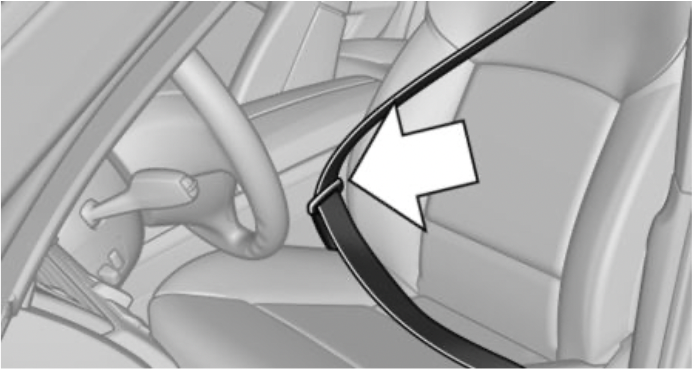
Unbuckling the safety belt
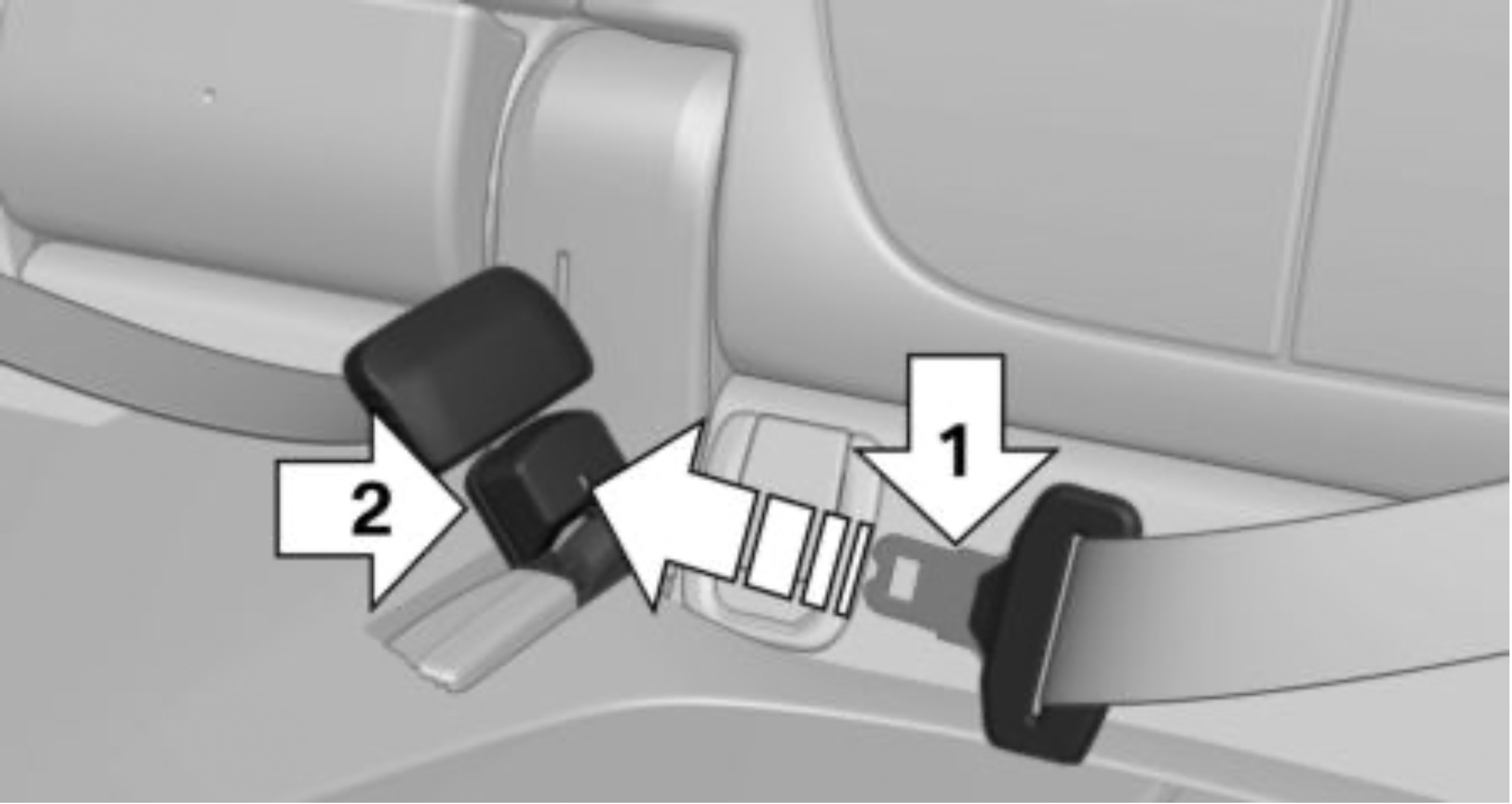
Middle safety belt in the rear
Buckling the safety belt
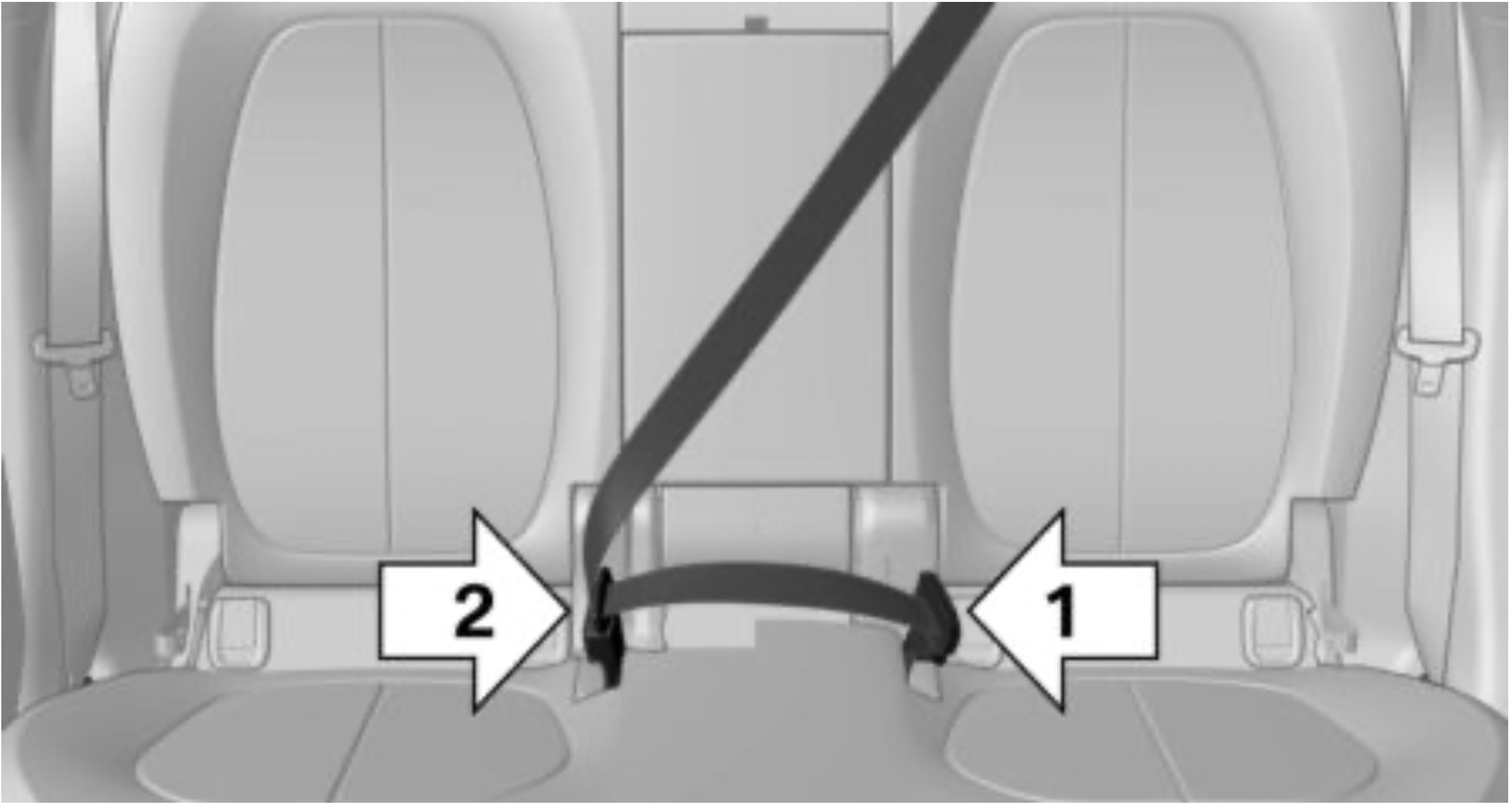
Unbuckling the safety belt
Safety belt reminder for driver's and passenger's seat
Display in the instrument cluster
The indicator light lights up and a signal sounds. Make sure that the safety belts are positioned correctly. The safety belt reminder can also be activated if objects are placed on the front passenger seat.
Safety information
WARNING
A missing protective effect due to removed or not correctly adjusted head restraints can cause injuries in the head and neck area. There is a risk of injury.
WARNING: Body parts can be jammed when moving the head restraint. There is a risk of injury. Make sure that the area of movement is clear when moving the head restraint.
WARNING: Objects on the head restraint reduce the protective effect in the head and neck area. There is a risk of injury.
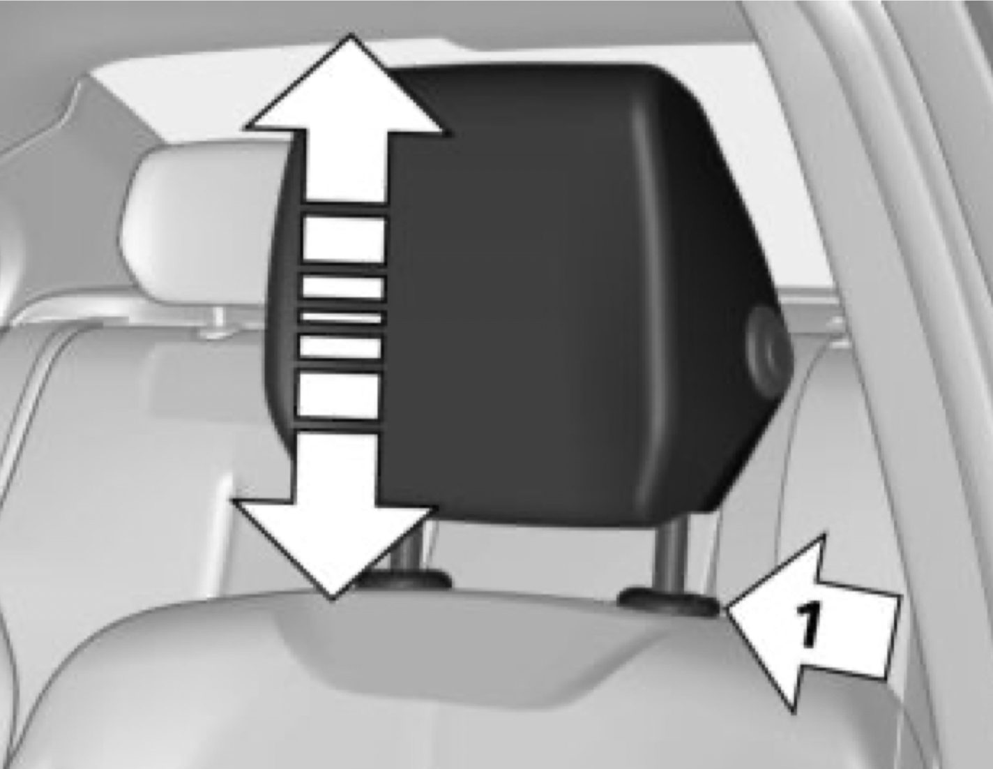
Adjusting the height
After setting the height, move the head restraint up or down slightly, making sure it engages properly.
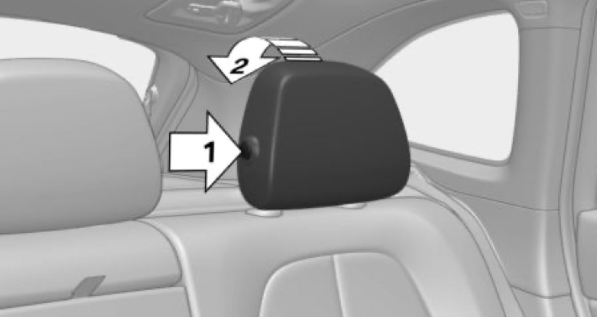
Removing
Only remove the head restraint if no one will be sitting in the seat in question.

Installing
Proceed in the reverse order to install the head restraint.
Safety information
WARNING
A missing protective effect due to removed or not correctly adjusted head restraints can cause injuries in the head and neck area. There is a risk of injury.
WARNING: Body parts can be jammed when moving the head restraint. There is a risk of injury. Make sure that the area of movement is clear when moving the head restraint.
WARNING
Objects on the head restraint reduce the protective effect in the head and neck area. There is a risk of injury.
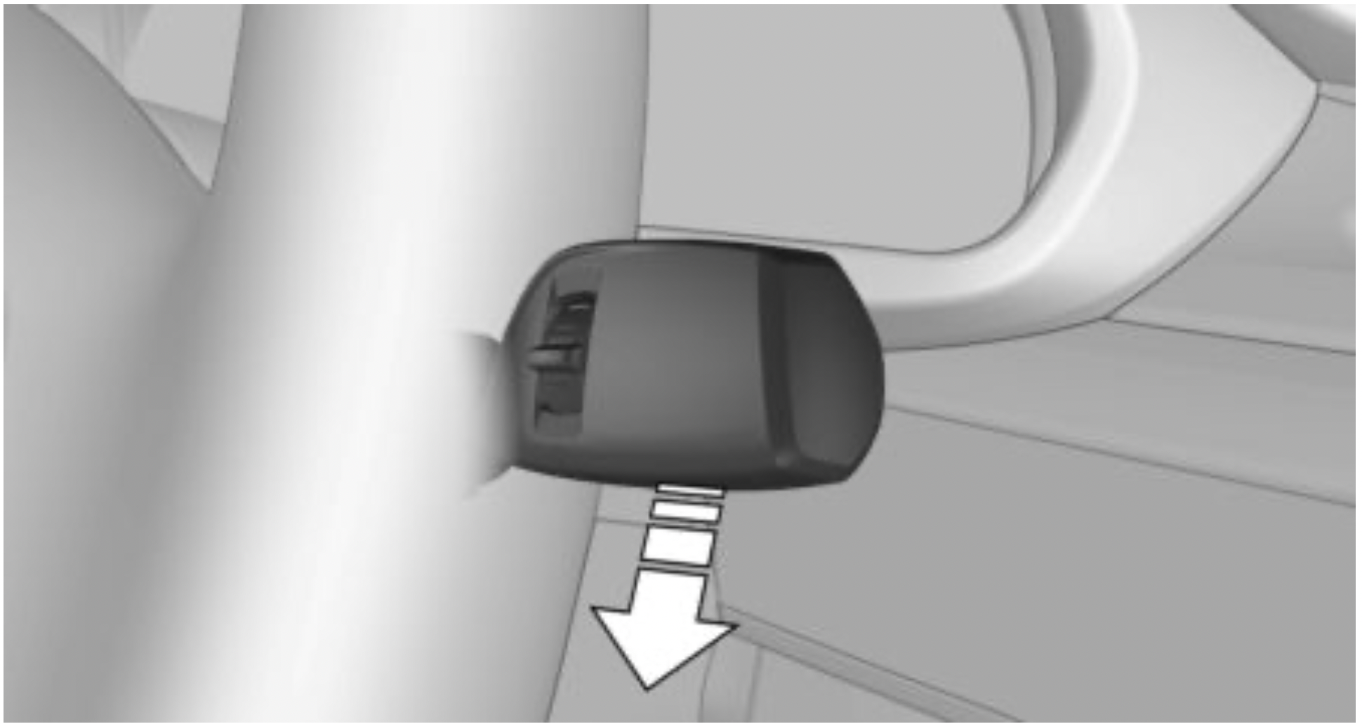
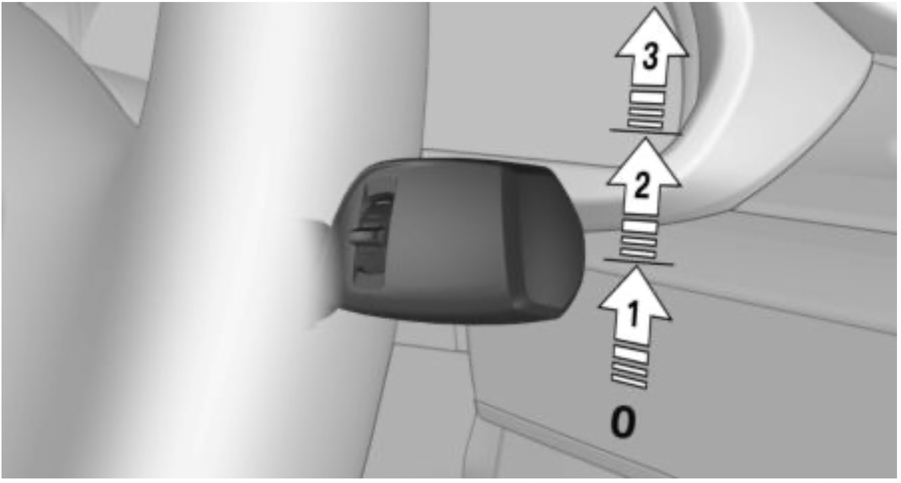
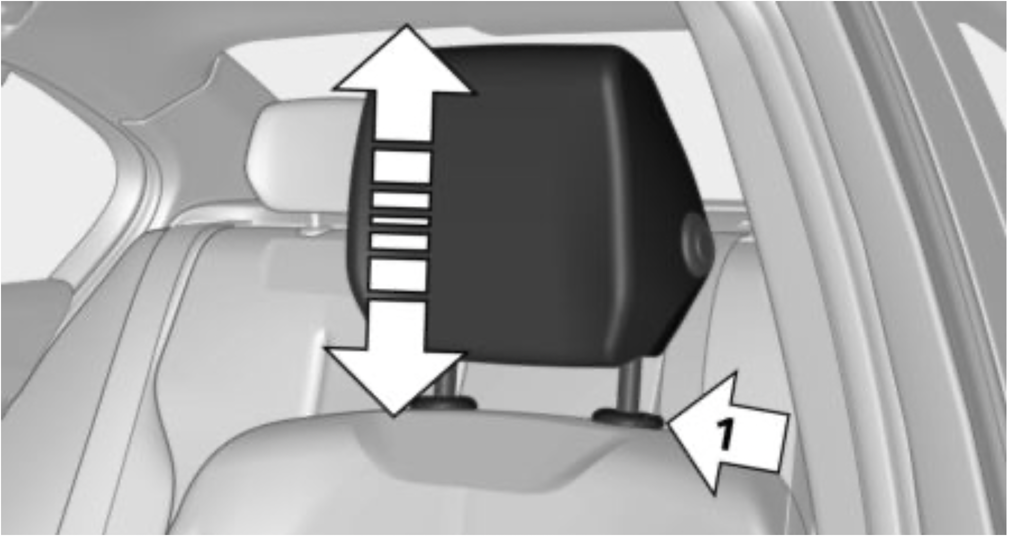
Height
Settings
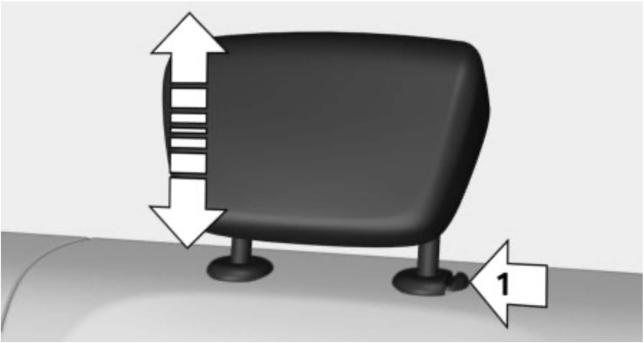
After setting the height, move the head restraint up or down slightly, making sure it engages properly.
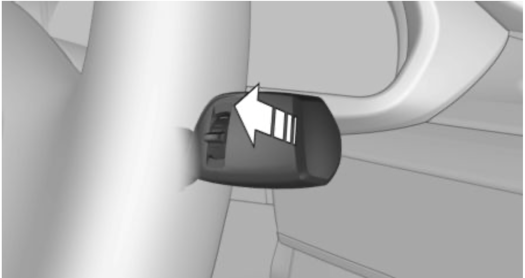
Folding down the head restraint
Only fold the head restraint back if no one will be sitting in the seat in question.
Removing
The head restraints cannot be removed.
Concept
The following settings can be stored and, if necessary, retrieved using the memory function:
General information
Different settings can be assigned to two memory locations.
Depending on the vehicle equipment, the following settings are not stored:
Safety information
WARNING: Using the memory function while driving can lead to unexpected movements of the seat. Vehicle control could be lost. There is a risk of an accident. Only retrieve the memory function when the vehicle is stationary.
WARNING: There is a risk of jamming when moving the seats. There is a risk of injury or risk of damage to property. Make sure that the area of movement of the seat is clear prior to any adjustment.
Overview
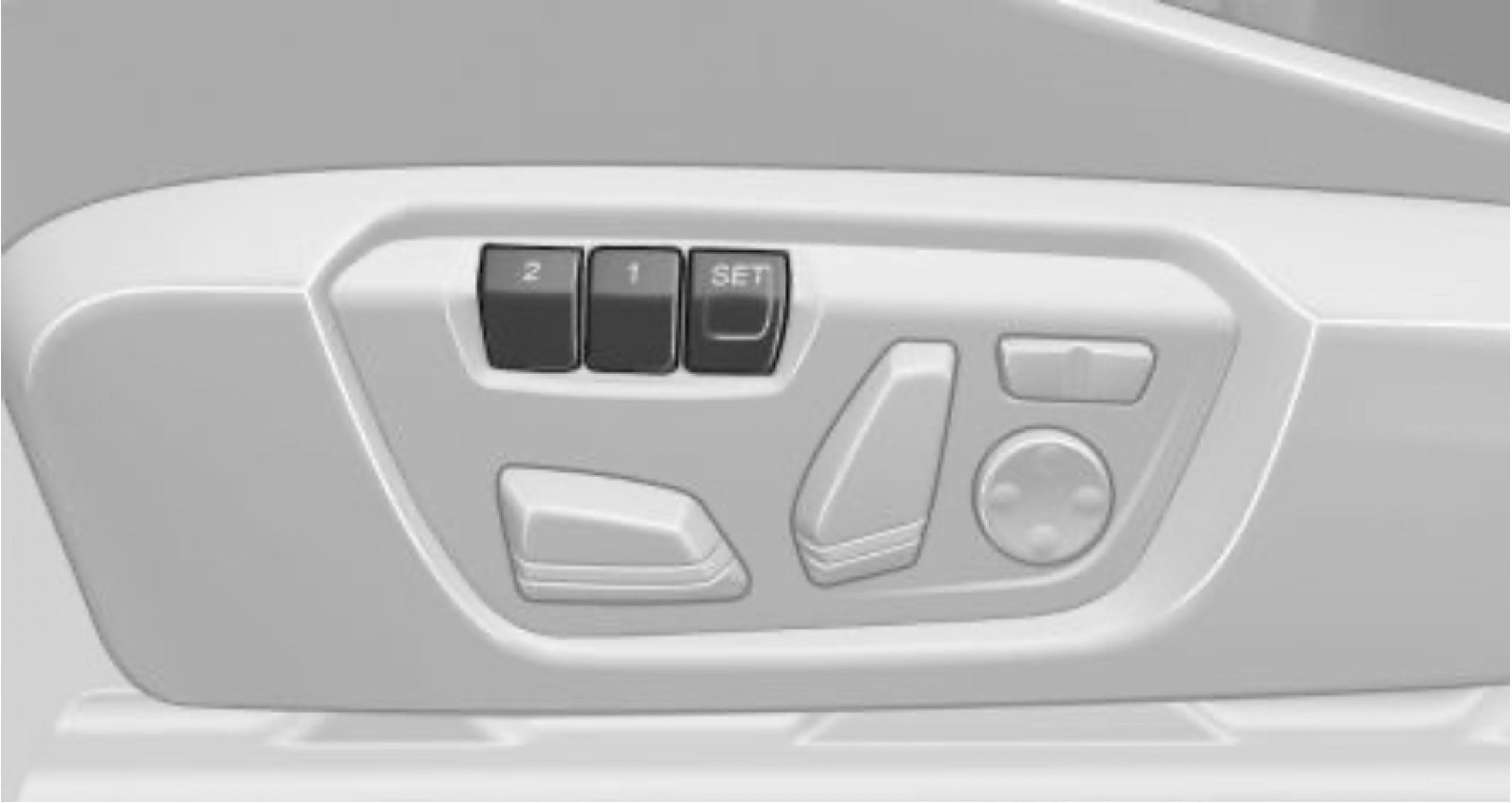
Storing
 Press button. The LED in the button lights up.
 Button was pressed inadvertently: Press button again. The LED goes out.
The stored position is called up automatically.
Press selected button 1 or 2.
The procedure stops when a switch for setting the seat or one of the memory buttons is pressed.
While driving, the seat position adjustment on the driver's side is interrupted after a short time.
After a brief period, calling up stored seat positions is deactivated to save battery power.
To reactivate calling up of a seat position:
Exterior mirrors
General information
The mirror on the front passenger side is more curved than the driver's side mirror.
The mirror setting is stored for the driver profile currently in use. When the vehicle is unlocked via the remote control, the position is automatically retrieved if the function, refer to page 85, is activated for this purpose.
The current exterior mirror position can be stored using the memory function, refer to page 98.
Safety information
WARNING: Objects reflected in the mirror are closer than they appear. The distance to the traffic behind could be incorrectly estimated, for instance while changing lanes. There is a risk of an accident. Estimate the distance to the traffic behind by looking over your shoulder.
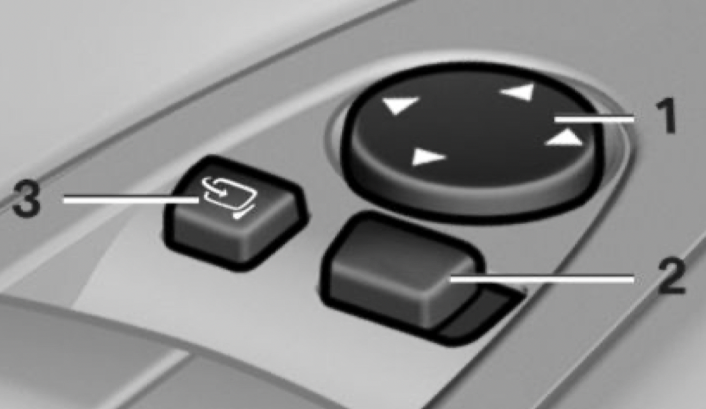
Overview
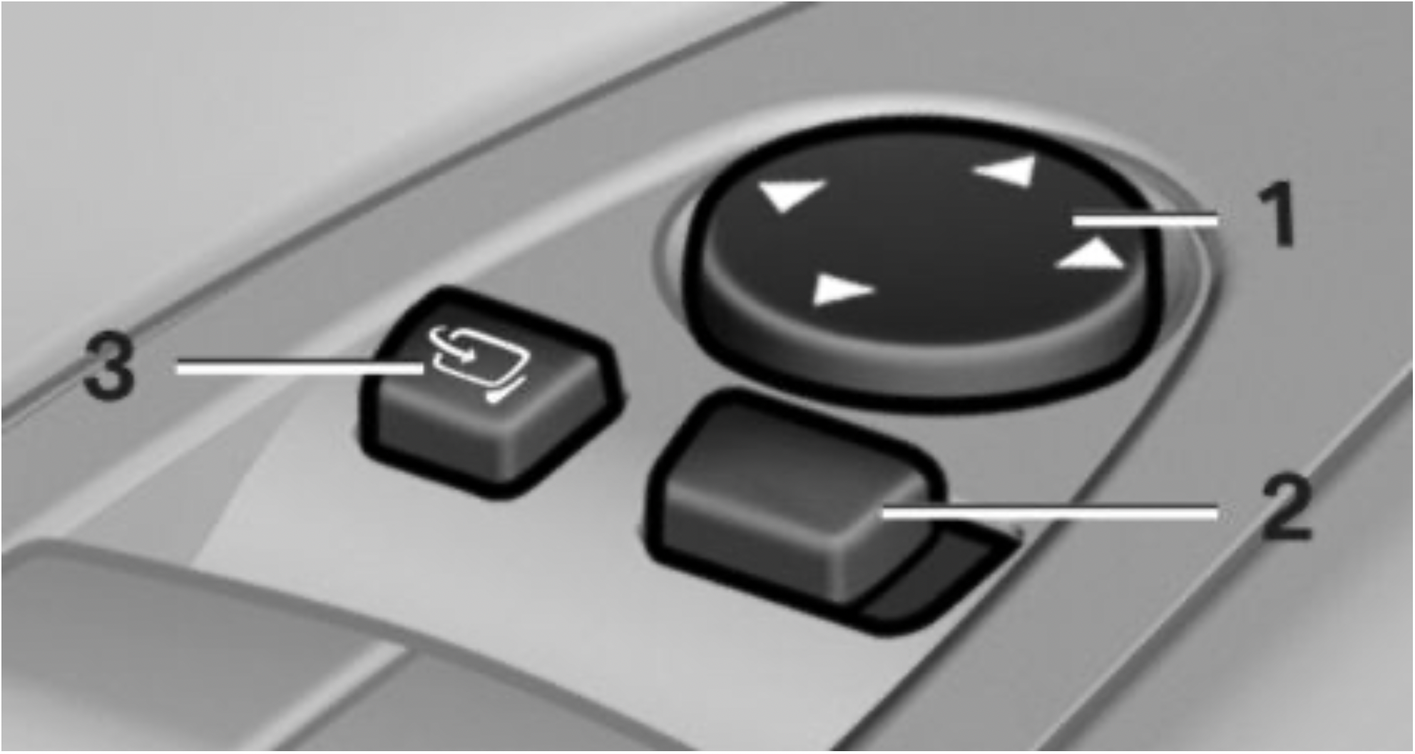
Selecting a mirror
 To change over to the other mirror: Slide the switch.
Adjusting electrically
 Press button. The mirror movement follows the button movement.
Malfunction
In case of an electrical malfunction, adjust the mirror by pressing the edges of the mirror glass.
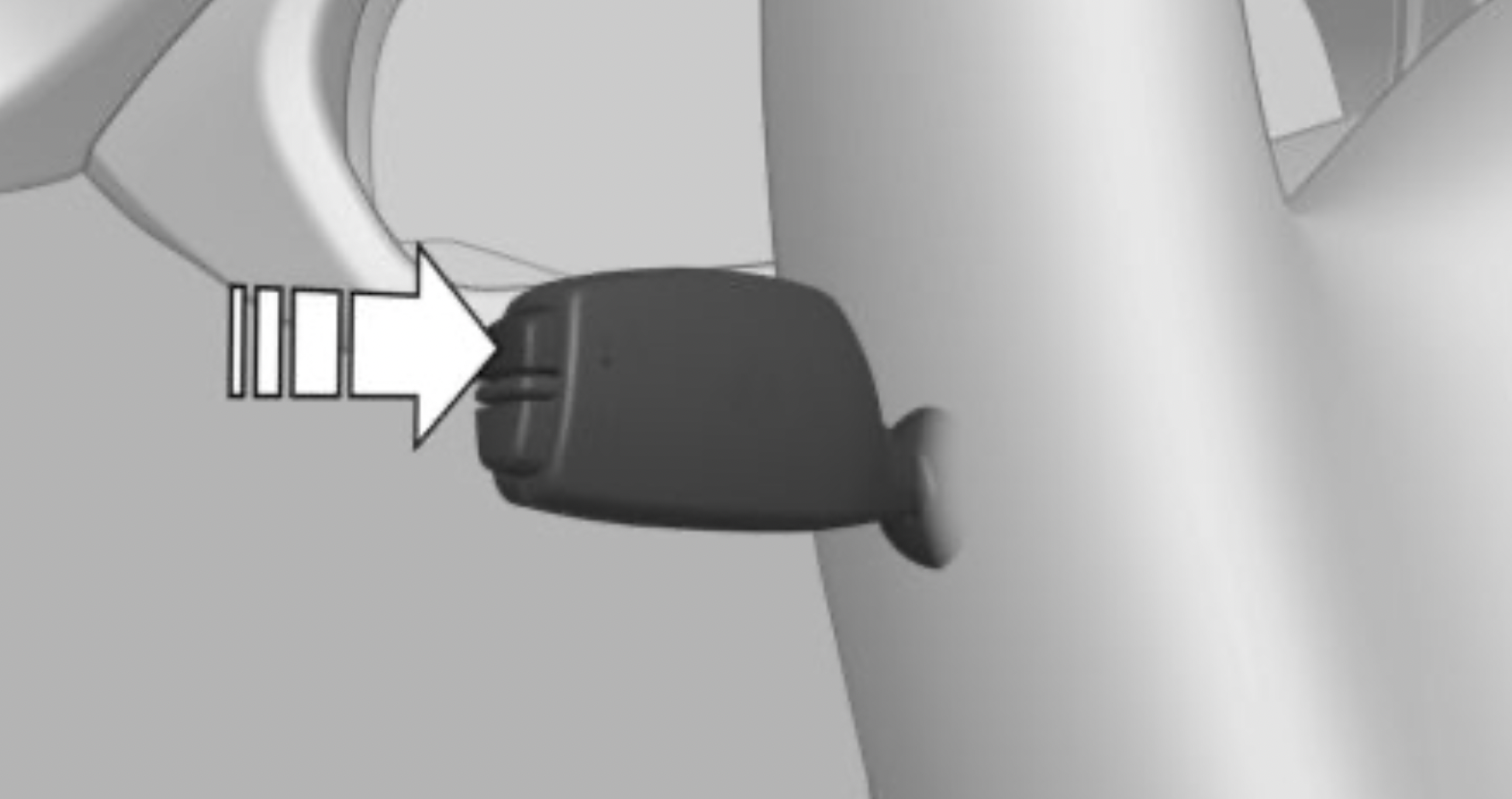
Folding in and out
NOTE: Depending on the vehicle width, the vehicle can be damaged in vehicle washes. There is a risk of damage to property. Before washing, fold in the mirrors by hand or with the button.
 Press button.
Folding is only possible up to a speed of approx. 15 mph/20 km/h.
Folding the mirrors in and out is helpful in the following situations:
Mirrors that were folded in are folded out automatically at a speed of approx. 25 mph/40 km/h.
Automatic heating
Both exterior mirrors are automatically heated whenever the ignition is switched on.
Automatic dimming feature
The exterior mirror on the driver's side is automatically dimmed. Photocells in the interior mirror are used to control this.
Automatic Curb Monitor, exterior mirror
Concept
If reverse gear is engaged, the mirror glass on the front passenger side is tilted downward. This improves your view of the curb and other low-lying obstacles when parking, for instance.
Activating
 Slide the switch to the driver's side mirror position.
Deactivating
 Slide the switch to the passenger's side mirror position.
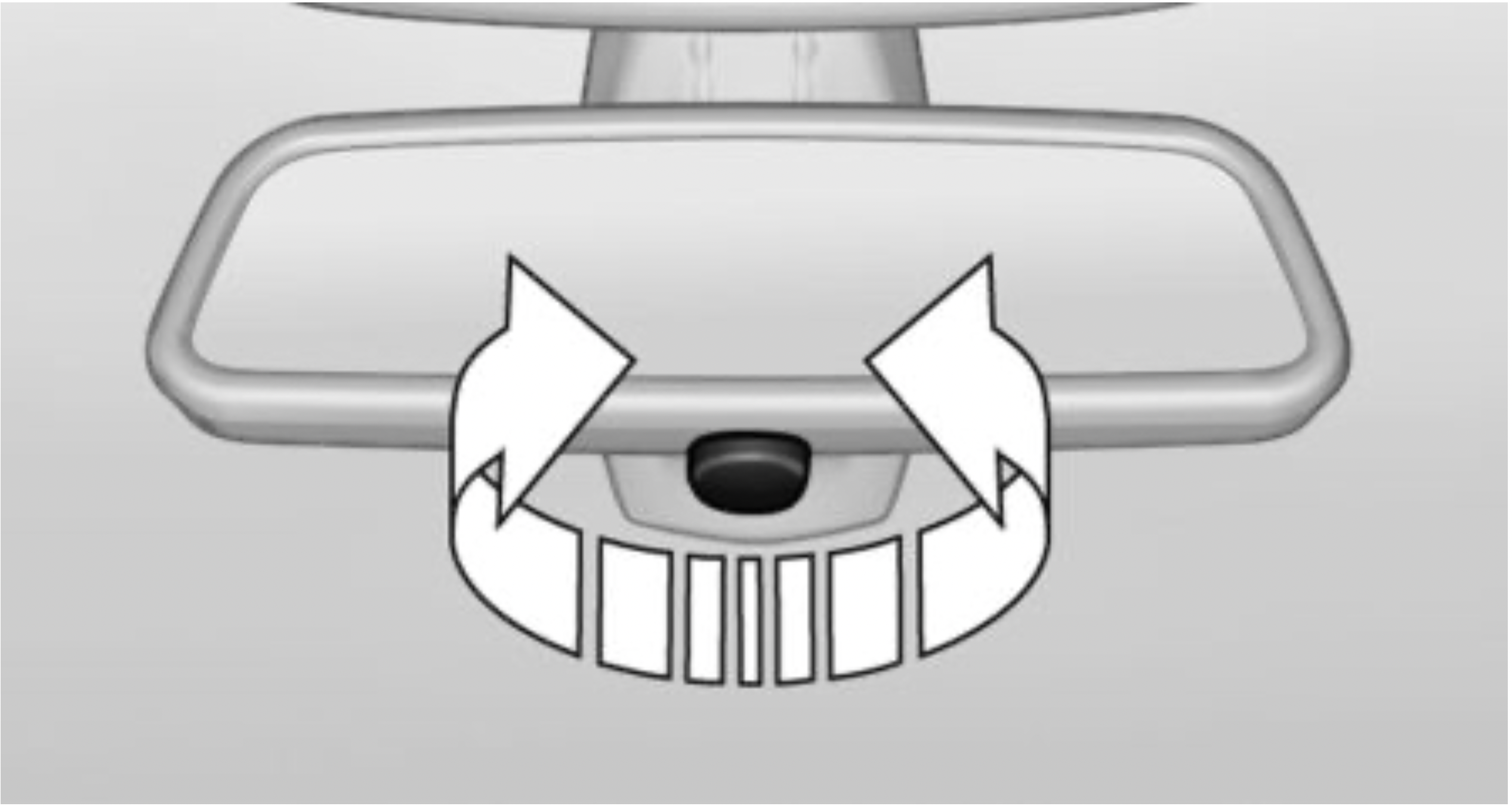
Interior mirror, manually dimmable
Turn knob
Turn the knob to reduce the blinding effect by the interior mirror.
Interior mirror, automatic dimming feature
Overview
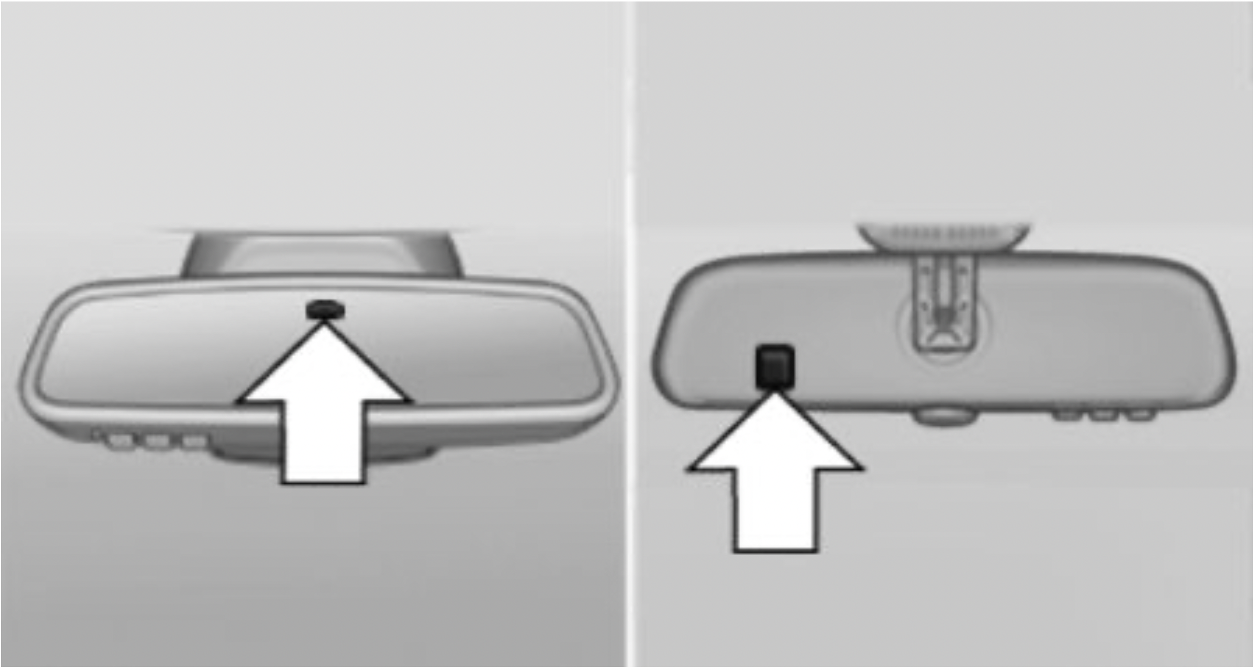
Photocells are used for control:
Functional requirements
Safety information
WARNING: Steering wheel adjustments while driving can lead to unexpected steering wheel movements. Vehicle control could be lost. There is a risk of an accident. Adjust the steering wheel while the vehicle is stationary only.
Settings
Overview
 Heated steering wheel
Switching on/off
 Press button.
This chapter describes all standard, country-specific and optional features offered with the series.
It also describes features that are not necessarily available in your vehicle, e. g., due to the selected options or country versions. This also applies to safety-related functions and systems. When using these functions and systems, the applicable laws and regulations must be observed.
Concept
The Check Control system monitors functions in the vehicle and notifies you of malfunctions in the monitored systems.
General information
A Check Control message is displayed as a combination of indicator or warning lights and SMS text messages in the instrument cluster and in the Head-up Display.
In addition, an acoustic signal may sound and an SMS text message may appear on the Control Display.
Indicator/warning lights
General information
The indicator/warning lights in the instrument cluster can light up in a variety of combinations and colors.
Several of the lights are checked for proper functioning and light up temporarily when the engine is started or the ignition is switched on.
Red lights
Safety belt reminder
 Safety belt on the driver's side is not buckled. For some country versions: passenger belt is not worn or objects are detected on the front passenger seat.
Indicator light flashes or is illuminated: safety belt on the driver or passenger side is not buckled. The safety belt reminder can also be activated if objects are placed on the front passenger seat.
Make sure that the safety belts are positioned correctly.
Airbag system
 Airbag system and belt tensioner are not working.
Have the vehicle checked immediately by a dealer’s service center or another qualified service center or repair shop.
Parking brake
 The parking brake is set.
Release the parking brake, refer to page 112.
Brake system
 Braking system impaired. Continue to drive moderately.
 Have the vehicle checked immediately by a dealer’s service center or another qualified service center or repair shop.
Approach control warning
 Indicator light illuminates: advance warning is issued, for example when there is the impending danger of a collision or the distance to the vehicle ahead is too small.
Increase distance.
Indicator light flashes: acute warning of the imminent danger of a collision when the vehicle approaches another vehicle at a relatively high differential speed.
Intervention by braking or make an evasive maneuver.
Person warning
 Symbol in the instrument cluster.
If a collision with a person detected in this way is imminent, the symbol lights up and a signal sounds.
Orange lights
Active Cruise Control
 The number bars shows the selected distance from the vehicle driving ahead.
Camera-based cruise control with Stop&Go function, ACC, refer to page 178.
Vehicle detection, Active Cruise Control
 Indicator light illuminates: a vehicle has been detected ahead of you.
Indicator light flashes: the conditions are not adequate for the system to work.
The system was deactivated but applies the brakes until you actively resume control by pressing on the brake pedal or accelerator pedal.
Yellow lights
Anti-lock Braking System ABS
 Braking force boost may not be working. Avoid abrupt braking. Take the longer braking distance into account.
 Have the system immediately checked by a dealer’s service center or another qualified service center or repair shop.
DSC Dynamic Stability Control
 The indicator light flashes: DSC controls the drive and braking forces. The vehicle is stabilized. Reduce speed and modify your driving style to the driving circumstances.
The indicator light lights up: DSC has malfunctioned.
Have the system checked by a dealer’s service center or another qualified service center or repair shop.
DSC, refer to page 171.
DSC Dynamic Stability Control is deactivated or DTC Dynamic Traction Control is activated
 DSC is deactivated or DTC is activated.
DSC, refer to page 171, and DTC, refer to page 173.
Flat Tire Monitor FTM
 The Flat Tire Monitor signals a loss of tire inflation pressure in a tire.
Reduce your speed and stop cautiously. Avoid sudden braking and steering maneuvers.
Flat Tire Monitor, refer to page 158.
Tire Pressure Monitor TPM
 The indicator light lights up: the Tire Pressure Monitor reports a low tire inflation pressure or a flat tire. Follow the information in the Check Control message.
The indicator light flashes and then continuously lights up: no flat tire or loss of tire inflation pressure can be detected.
Tire Pressure Monitor, refer to page 153.
Steering system
 Steering system in some cases not working.
Have the system checked by a dealer’s service center or another qualified service center or repair shop.
Emissions
Socket for Onboard Diagnosis, refer to page 272.
Lane departure warning
 System is switched on and under certain circumstances warns if a detected lane is left without flashing beforehand.
Lane departure warning, refer to page 167.
Green lights
Turn signal
 Turn signal switched on.
Unusually rapid flashing of the indicator light indicates that a turn signal bulb has failed.
Turn signal, refer to page 113.
Parking lights, headlight
 Parking lights or headlights are switched on.
Parking lights/low beams, headlight control, refer to page 145.
Front fog lights
 Front fog lights are switched on.
Front fog lights, refer to page 148.
High-beam Assistant
 High-beam Assistant is switched on.
High beams are switched on and off automatically depending on the traffic situation.
High-beam Assistant, refer to page 147.
Cruise control
 The system is switched on. It maintains the speed that was set using the control elements on the steering wheel.
Blue lights
High beams
 High beams are switched on.
High beams, refer to page 113.
Hiding Check Control messages
Press and hold button on signal lever.
Continuous display
Some Check Control messages are displayed continuously and are not cleared until the malfunction is eliminated. If several malfunctions occur at once, the messages are displayed consecutively.
The messages can be hidden for approx. 8 seconds. After this time, they are displayed again automatically.
Temporary display
Some Check Control messages are hidden automatically after approx. 20 seconds. The Check Control messages are stored and can be displayed again later.
Displaying stored Check Control messages
Via iDrive:
 "Check Control"
Display
Check Control
 At least one Check Control message is displayed or is stored.
SMS text messages
SMS text messages in combination with a symbol in the instrument cluster explain a Check Control message and the meaning of the indicator/warning lights.
Supplementary SMS text messages
Additional information, such as on the cause of an error or the required action, can be called up via Check Control.
With urgent messages the added text will be automatically displayed on the Control Display.
Functions
Depending on the Check Control message, the following functions can be selected.
Messages after trip completion
Special messages displayed while driving are displayed again after the ignition is switched off.
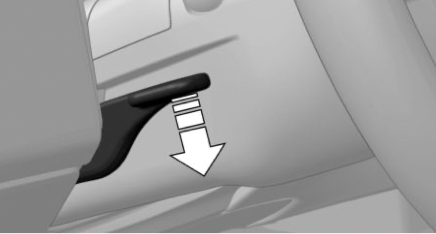
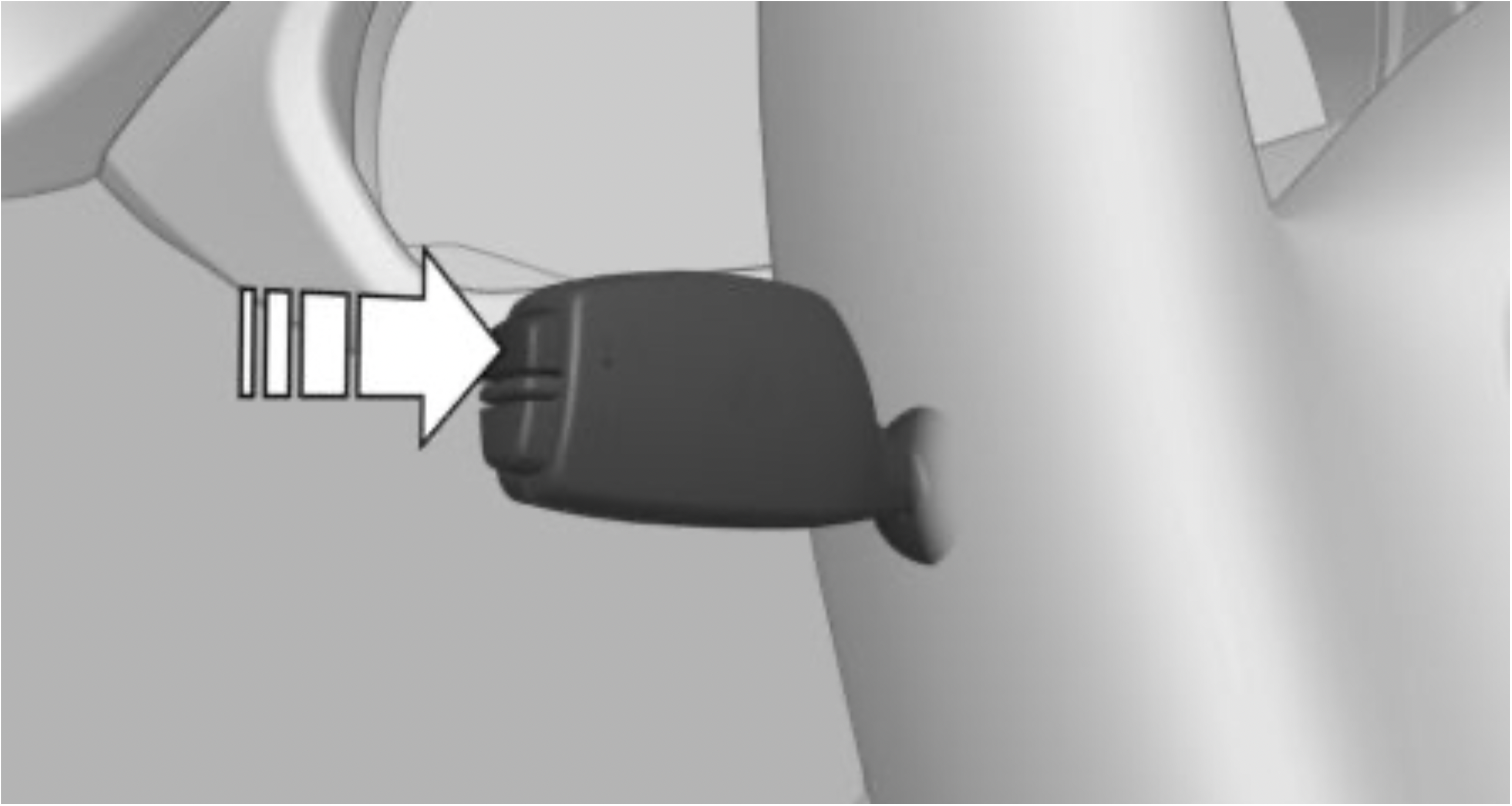
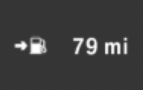
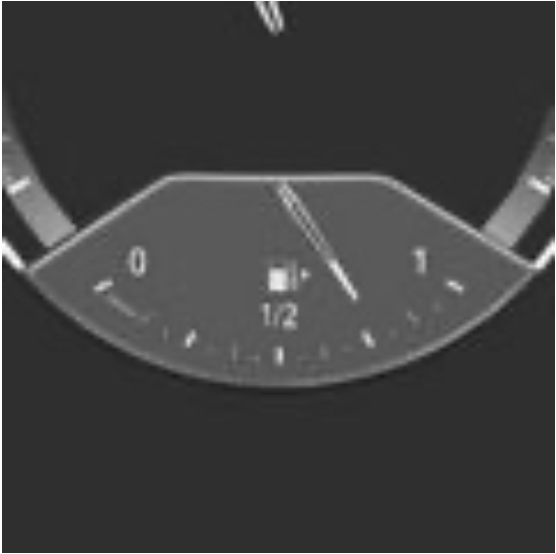 An arrow beside the fuel pump symbol shows which side of the vehicle the fuel filler flap is on.
Vehicle tilt position may cause the display to vary.
Follow the information on refueling.
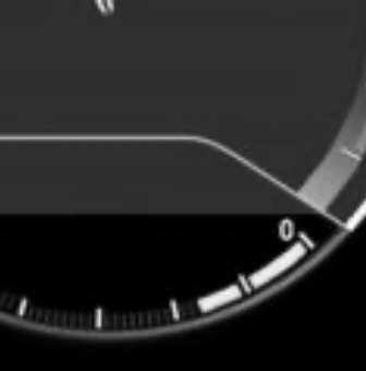
 The yellow indicator light illuminates, once the fuel reserve is reached.
Always avoid engine speeds in the red warning field. In this range, the fuel supply is reduced to protect the engine.
Display
Show/reset miles
Press the button.
General information
If the indicator drops to +37 ℉/+3 ℃ or lower, a signal sounds.
A Check Control message is displayed.
There is an increased risk of ice on roads.
Safety information
WARNING: Even at temperatures above +37 ℉/+3 ℃ there can be a risk of icy roads, for instance on bridges or shady sections of road. There is a risk of an accident. Modify your driving style to the weather conditions at low temperatures.
Display
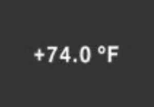
The external temperature is displayed in the instrument cluster.

The time is displayed in the instrument cluster.
The time can be set on the Control Display.

The date is displayed in the instrument cluster.
The date can be set on the Control Display.
General information
With a low remaining range:
The Check Control message appears continuously below a range of approx. 30 miles/50 km.
Safety information
NOTE: With a driving range of less than 30 miles/50 km the engine may no longer have sufficient fuel. Engine functions are not ensured anymore. There is a risk of damage to property. Refuel promptly.
Display
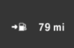
The current range is displayed in the instrument cluster.
Instrument cluster
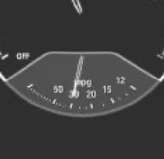
Displays the current fuel consumption. Check whether you are currently driving in an efficient and environmentally-friendly manner.
Instrument cluster with enhanced features
Displays the current fuel consumption. Check whether you are currently driving in an efficient and environmentally-friendly manner.
Displaying the current fuel consumption
Depending on your vehicle's optional features, the current fuel consumption can also be displayed as bar in the instrument cluster.
Via iDrive:
Display
 In coasting overrun mode the kinetic energy of the vehicle is converted to electrical energy. The vehicle battery is partially charged and fuel consumption can be reduce.
Concept
The function displays the service requirements and the corresponding maintenance scopes.
General information
After the ignition is switched on the instrument cluster briefly displays available driving distance or time to the next scheduled maintenance.
A service advisor can read out the current service requirements from your remote control.
Display
Detailed information on service requirements
More information on the type of service required may be displayed on the Control Display.
Via iDrive:
 "Service required"
Symbols
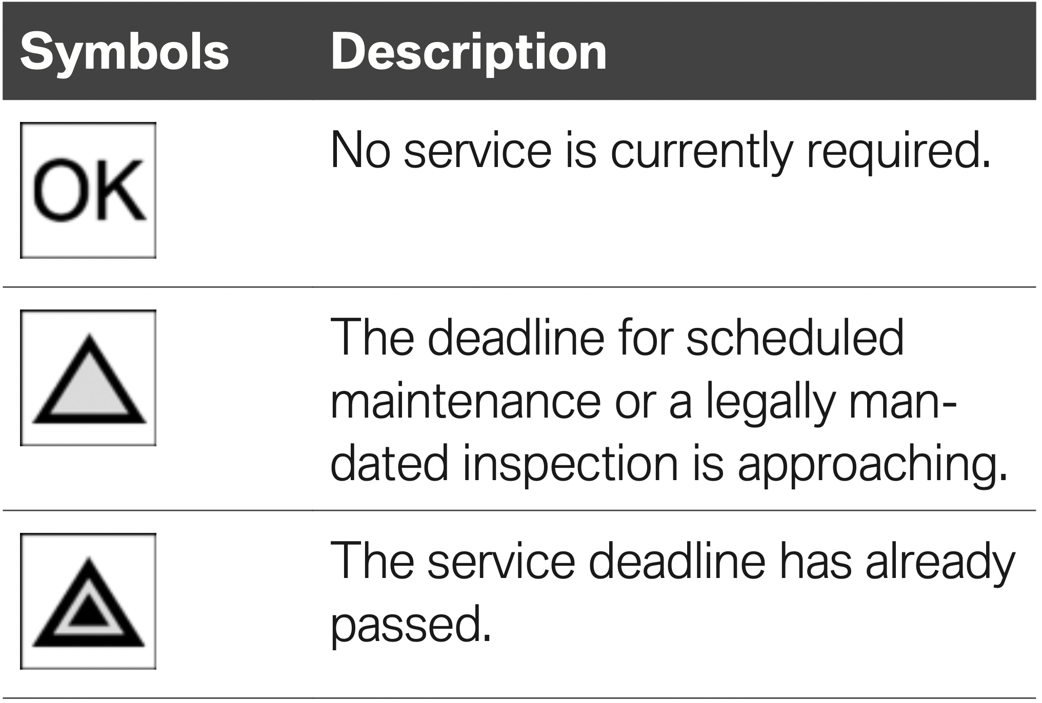
Entering appointment dates
Enter the dates for the mandatory vehicle inspections.
Make sure that the vehicle's date and time are set correctly.
Via iDrive:
 "Service required"
Automatic Service Request
Data regarding the service status or legally mandated vehicle inspections is automatically transmitted to your dealer’s service center before your vehicle is due for service.
You can check when your dealer’s service center was notified.
Via iDrive:
 "Teleservice Call"
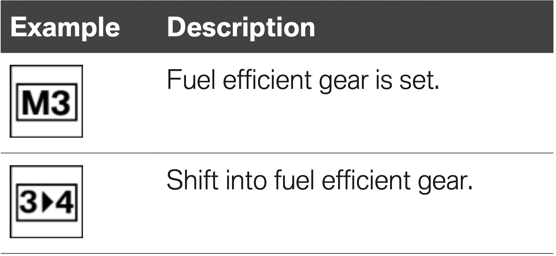
Concept
The system recommends the most fuel efficient gear for the current driving situation.
General information
Depending on the vehicle equipment and country version, the gear shift indicator is active in the manual mode of the Steptronic transmission and with manual transmission.
Suggestions to shift gear up or down are displayed in the instrument cluster.
On vehicles without a gear shift indicator, the engaged gear is displayed.
Steptronic transmission: displaying
Speed Limit Info
Concept
Speed Limit Info shows the current maximum permitted speed in the instrument cluster.
General information
The camera in the area of the interior mirror detects traffic signs at the edge of the road as well as variable overhead sign posts. Traffic signs with extra symbols for wet road conditions, etc., are also detected and compared with the vehi cle's onboard data, such as from the rain sensor, and will be displayed depending on the situation.
With the navigation system, the system takes into account the information stored in the navigation data and also displays speed limits present on routes without signs.
Without a navigation system, the system is subject to limitations imposed by technology. Traffic signs with speed limitations are detected and displayed only. Speed limitations due to entering or exiting towns, highway signs, etc. are not displayed. Speed limits with extra text characters are always displayed.
Safety information
WARNING: The system cannot serve as a substitute for the driver’s personal judgment in assessing visibility and traffic situation. There is a risk of an accident. Adjust driving style to traffic conditions. Watch traffic closely and actively intervene where appropriate.
Overview
Camera
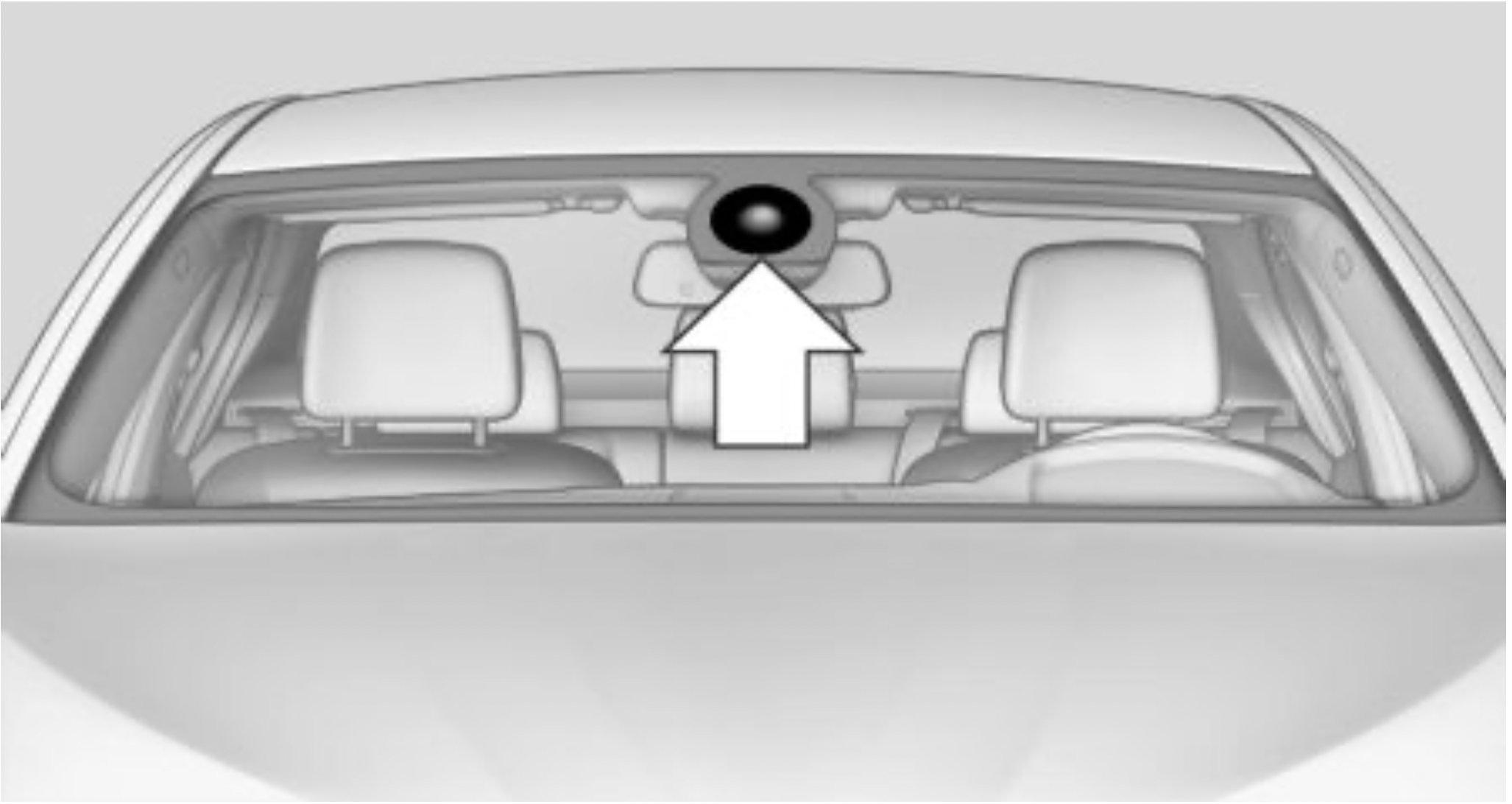
The camera is installed near the interior mirror.
Keep the windshield in front of the interior mirror clean and clear.
Display
General information
Speed Limit Info is permanently displayed in the instrument cluster.
Speed Limit Info

The last speed limit detected.
Without a navigation system the traffic signals are grayed out after curves or longer stretches of roadway.

With navigation system: Speed Limit Info not available.

Without navigation system: No speed limit or cancellation detected.
Speed Limit Info can also be displayed in the Head-up Display.
System limits
The system may not be fully functional and may provide incorrect information in the following situations:
General information
Depending on your vehicle's equipment, the following can be displayed or operated using the buttons and the thumbwheel on the steering wheel as well as the displays in the instrument cluster and the Head-up Display:
Activating a list and adjusting the setting
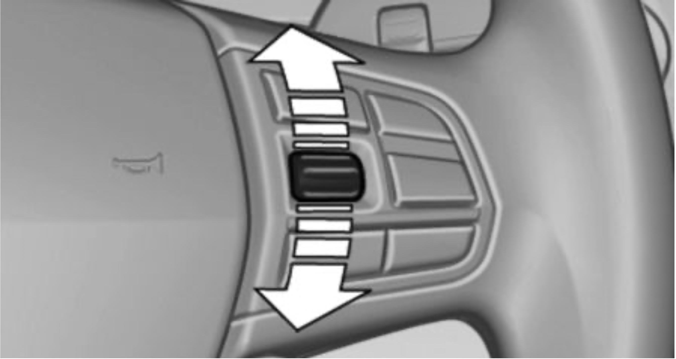
On the right side of the steering wheel, turn the thumbwheel to activate the corresponding list.
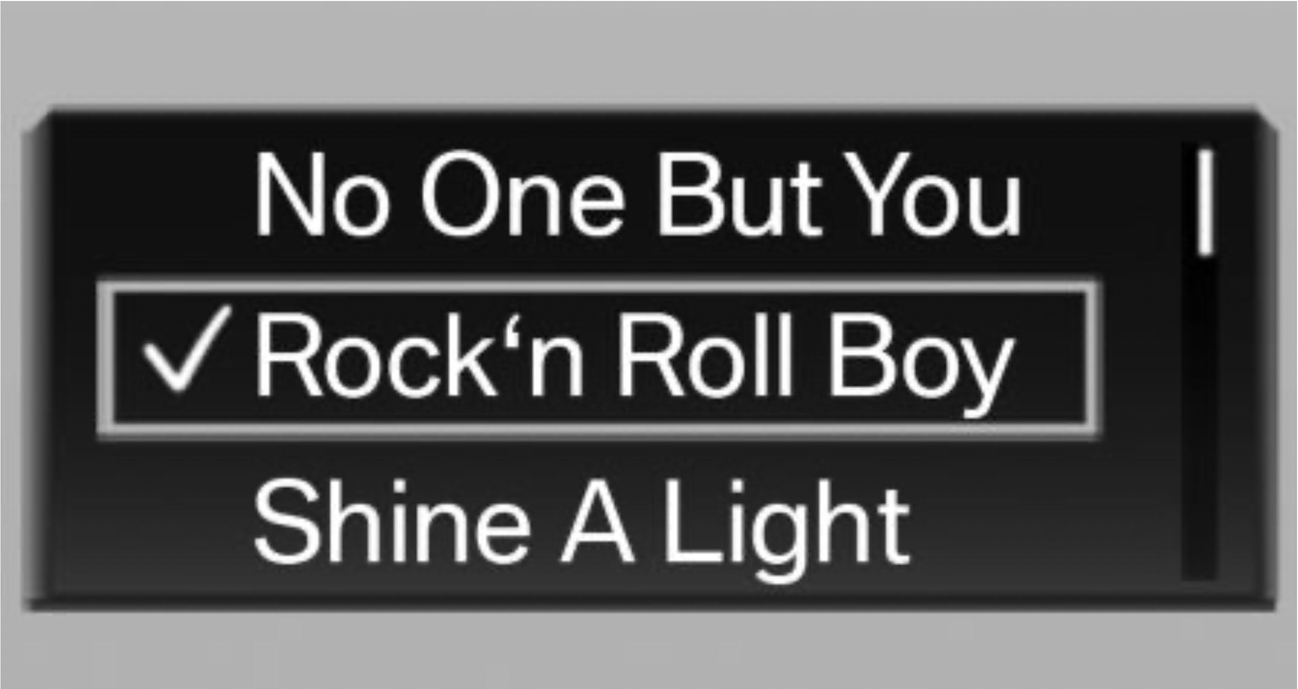
Display
Depending on the equipment version, the list in the instrument cluster may differ from the illustration.
Concept
The Onboard Computer displays different vehicle data in the instrument cluster, such as average values.
Calling up information on the Info Display
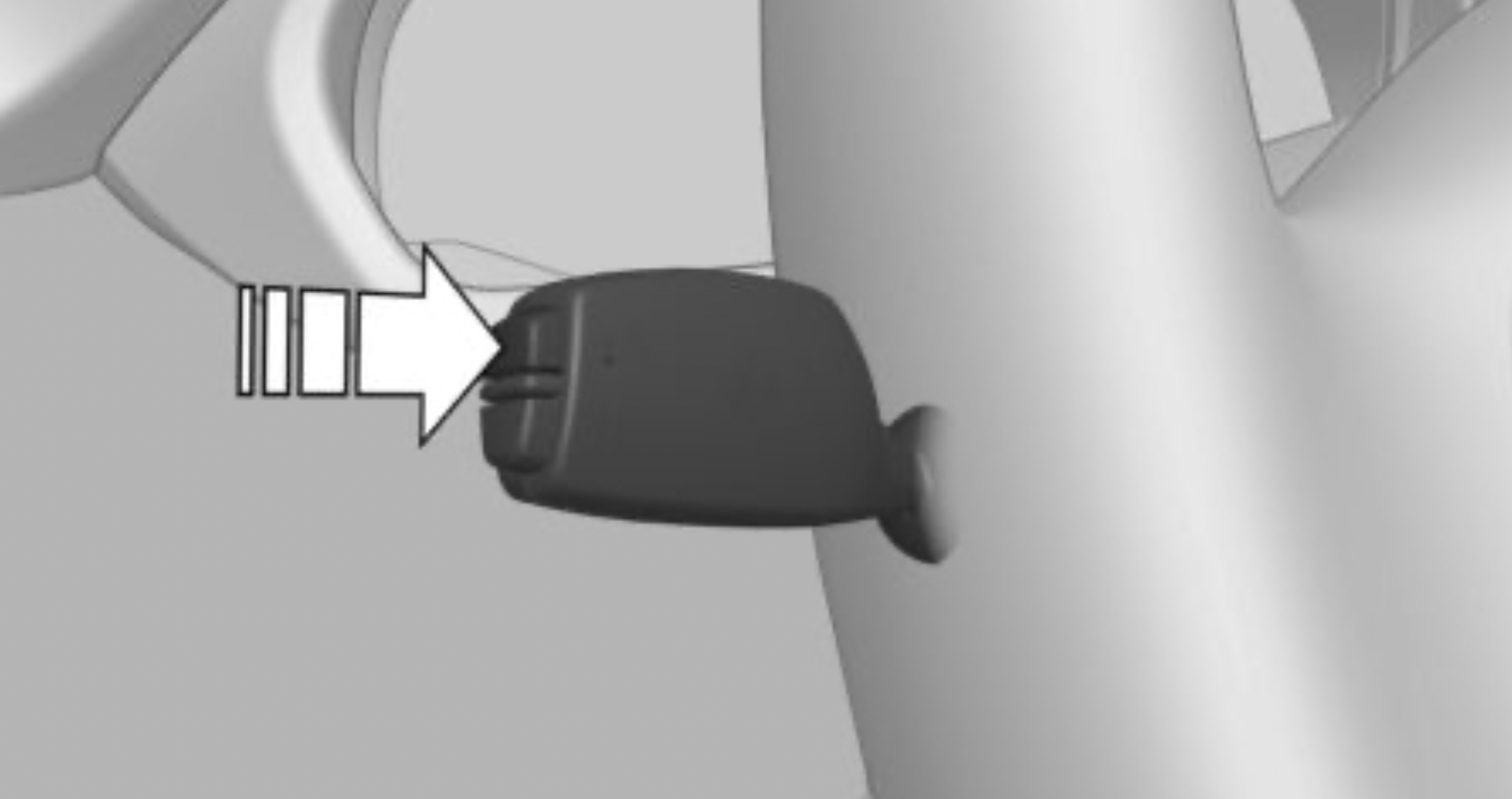
Press and hold button on signal lever. Information is displayed in the Info Display of the instrument cluster. Pressing the button repeatedly displays additional information.
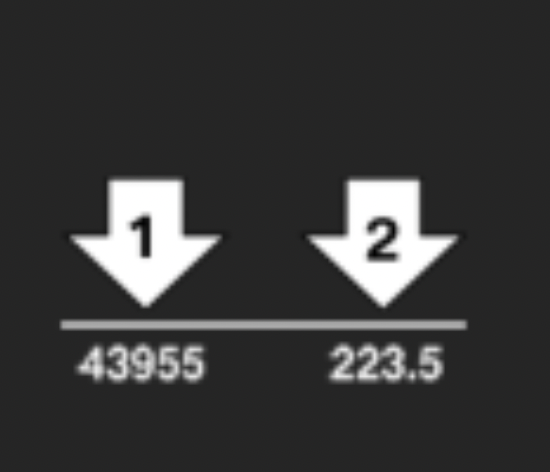
Information at a glance
Repeatedly pressing the button on the turn signal lever calls up the following information in the Info Display:
Selecting information
You can select what information from the Onboard Computer is to be displayed on the Info Display of the instrument cluster.
Via iDrive:
Indication in the Info Display
 The information from the Onboard Computer is shown in the Info Display in the instrument cluster.
Information in detail
Range
Displays the estimated cruising range available with the remaining fuel.
The range is calculated based on your driving style over the last 20 miles/30 km.
Average fuel consumption
The average fuel consumption is calculated for the period while the engine is running.
The average fuel consumption is calculated for the distance traveled since the last reset by the Onboard Computer.
Average speed
Periods in which the vehicle is parked with the engine manually stopped are not included in the calculation of the average speed.
Resetting average values
Press and hold button on turn signal lever.
Engine temperature display
Depending on the vehicle equipment, the current engine temperature is displayed, based on a combination of the coolant temperature and engine oil temperature. As soon as the optimum operating temperature has been attained, the indicator is in the center position.
If the engine oil or coolant, and thus the engine, become too hot, a Check Control message is displayed too.
Check the coolant level, refer to page 269.
Distance to destination
Depending on the vehicle equipment, the distance remaining to the destination is displayed if a destination is entered in the navigation system before the trip is started.
The distance to the destination is adopted automatically.
Time of arrival
 Depending on the vehicle equipment, the estimated time of arrival is displayed if a destination is entered in the navigation system before the trip is started.
The time must be correctly set.
Onboard Computer on the Control Display
Concept
The Onboard Computer displays different vehicle data on the Control Display, such as average values.
General information
Two types of Onboard Computers are available on the Control Display:
Calling up the Onboard Computer or trip computer
Via iDrive:
Resetting the Onboard Computer
Via iDrive:
Resetting the trip computer
Via iDrive:
 "Reset": all values are reset.
 "Automatic reset": all values are reset approx. 4 hours after the vehicle has come to a standstill.
Concept
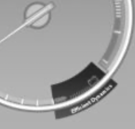
On the Control Display, sport instruments can be displayed, and the vehicle state can be checked before the use of the SPORT program.
Sport instruments
General information
On the Control Display, values for power and torque are displayed.
Displaying sport instruments
Via iDrive:
 "Sports instruments"
Via the Driving Dynamics Control
Vehicle state
General information
The following vehicle and environment data is evaluated:
Checking vehicle state
Via iDrive:
 "Vehicle and surroundings"
Via the Driving Dynamics Control
Concept
A speed limit can be set that when reached will cause a warning to be issued.
General information
The warning is repeated if the vehicle speed exceeds the set speed limit again, after it has dropped below it by 3 mph/5 km/h.
Displaying, setting or changing the speed warning
Via iDrive:
Activating/deactivating the speed warning
Via iDrive:
Setting your current speed as the speed warning
Via iDrive:
Concept
This system projects important information into the driver's field of vision, for instance the speed. The driver can quickly absorb information and concentrate on the traffic situation.
Overview
Switching on/off
Via iDrive:
Display
Overview
The following information is displayed on the Head-up Display:
Some of this information is only displayed briefly as needed.
Selecting displays in the Head-up Display
Via iDrive:
Settings are stored for the profile currently used.
Setting the brightness
The brightness is automatically adjusted to the ambient brightness.
The basic setting can be adjusted manually.
Via iDrive:
When the low beams are switched on, the brightness of the Head-up Display can be additionally influenced using the instrument lighting.
Settings are stored for the profile currently used
Adjusting the height
Via iDrive:
Settings are stored for the profile currently used. The height of the Head-up Display can also be stored using the memory function, refer to page 98.
Setting the rotation
The screen of the Head-up Display can be rotated around its own axis.
Via iDrive:
Settings are stored for the profile currently used.
Display visibility
The visibility of the displays in the Head-up Display is influenced by the following factors:
If the image is distorted, have the basic settings checked by a dealer’s service center or another qualified service center or repair shop.
Follow the instructions for cleaning the Head-up Display, refer to page 291.
Special windshield
The windshield is part of the system.
The shape of the windshield makes it possible to display a precise image.
A film in the windshield prevents double images from being displayed.
For this reason, it is strongly suggested to have the special windshield replaced by a dealer’s service center or another qualified service center or repair shop, if necessary.
General information
The status can be displayed and actions performed for several systems.
Opening the vehicle status
Via iDrive:
Information at a glance
 "Flat Tire Monitor": status of the Flat Tire Monitor, refer to page 158.
 "Tire Pressure Monitor": status of the Tire Pressure Monitor, refer to page 153.
 "Engine oil level": Electronic engine oil level check, refer to page 265.
 "Check Control": Check Control messages are stored in the background and can be displayed on the Control Display. Displaying stored Check Control messages, refer to page 133.
 "Service required": Displaying service requirements, refer to page 135.
 "Teleservice Call": service request.
This chapter describes all standard, country-specific and optional features offered with the series. It also describes features that are not necessarily available in your vehicle, e. g., due to the selected options or country versions. This also applies to safety-related functions and systems. When using these functions and systems, the applicable laws and regulations must be observed.
The air quality inside the vehicle is improved by an emissions-tested interior, a microfilter, and a climate-control system for regulating temperature, air flow, and recirculated-air mode.
In addition there are other functions which depend on the vehicle's equipment, for instance microfilter/activated-charcoal filter, automatic climate control with automatic recirculated-air control AUC, and parked-car ventilation.
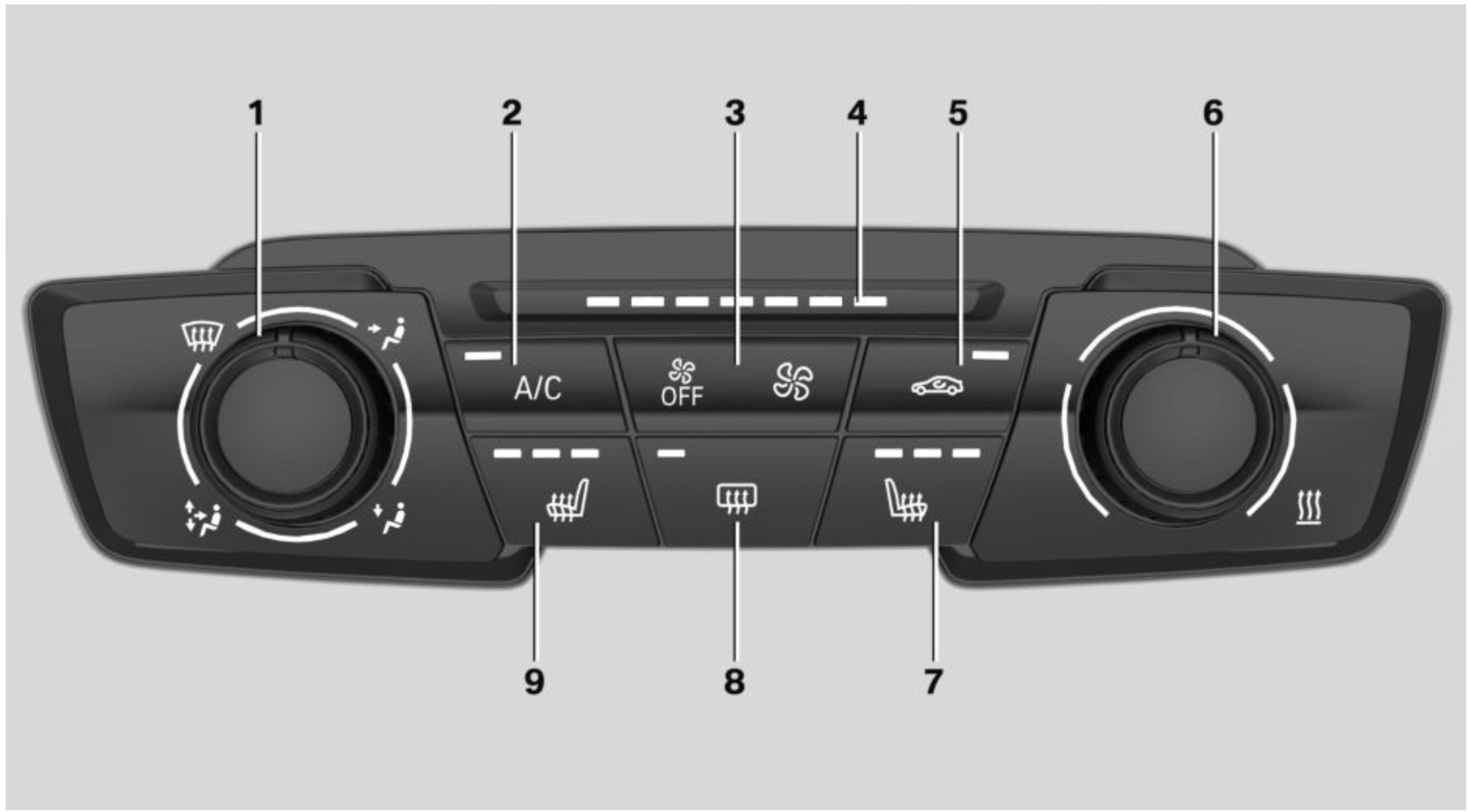
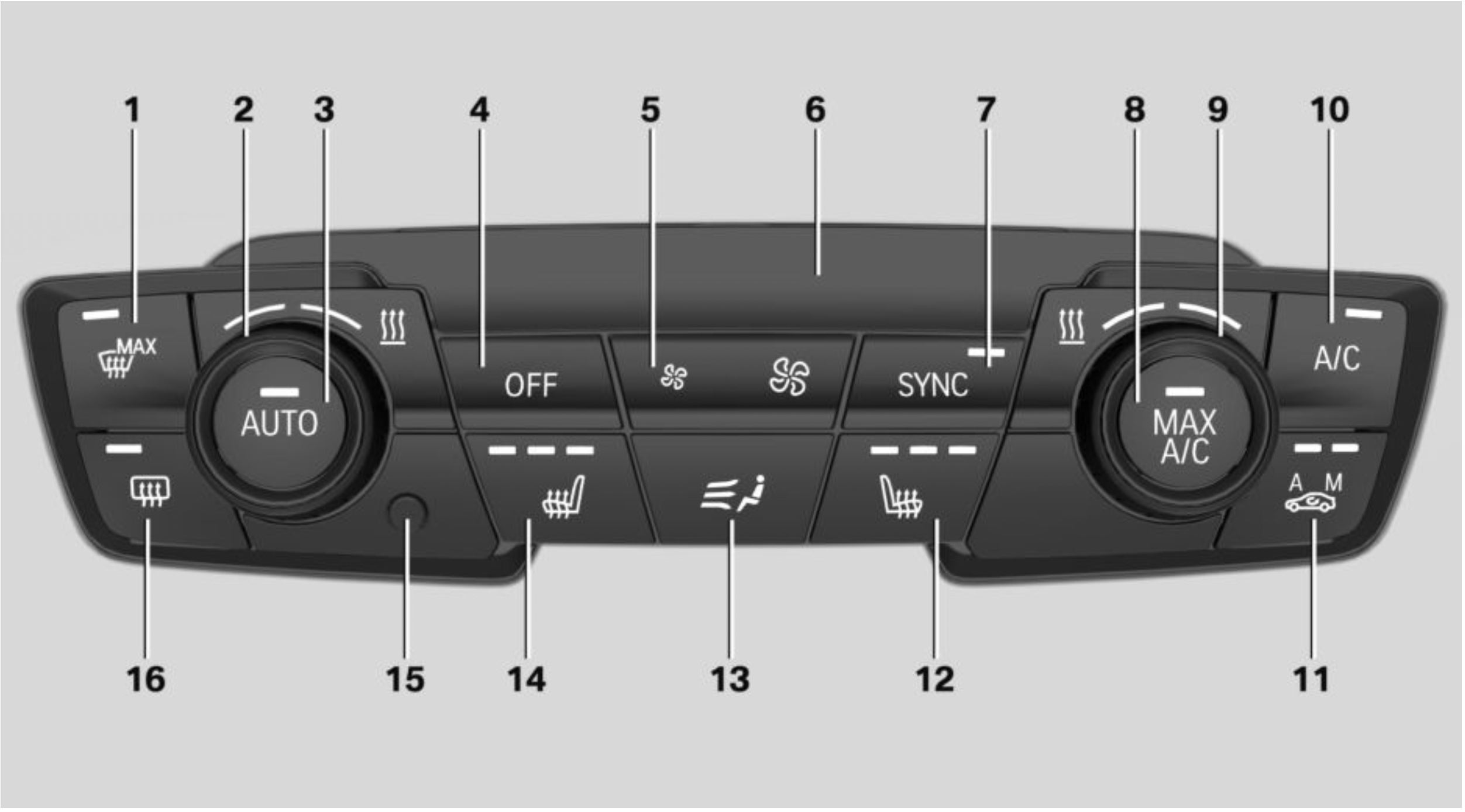
Climate control functions in detail
Switching the system on/off
Switching on
Press any button except for the following:
Switching off
 Press and hold the left button until the control switches off.
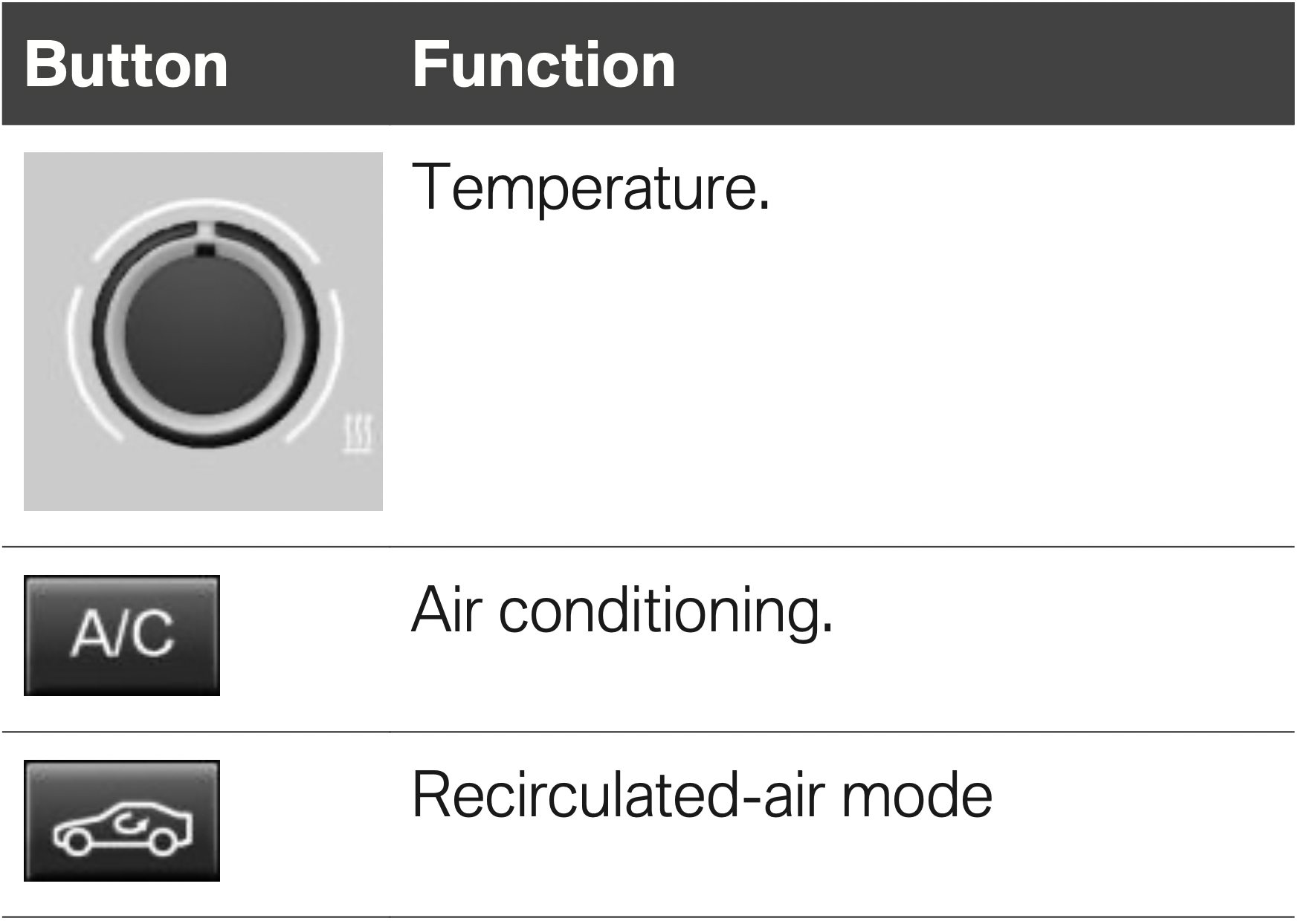
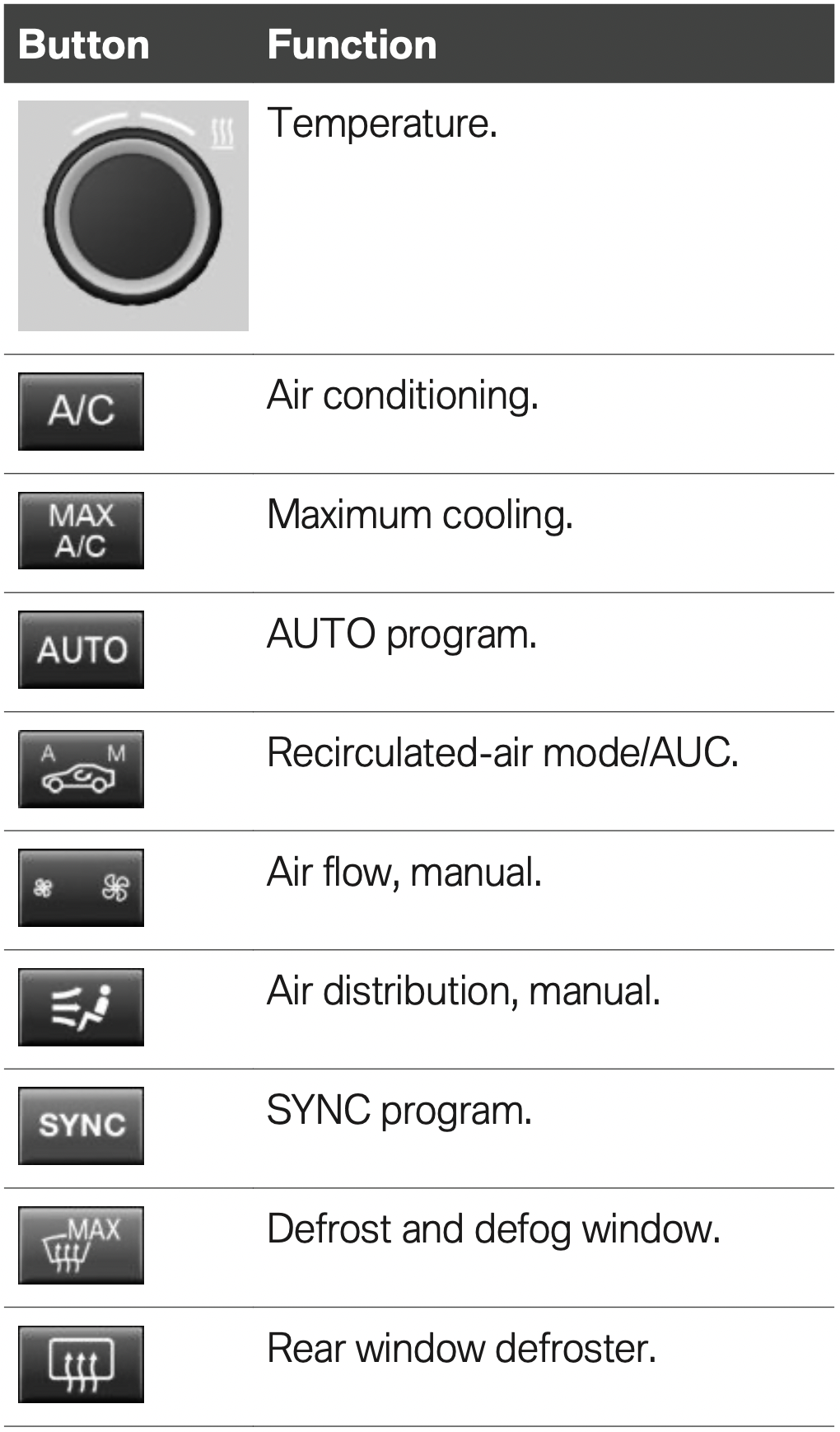
Temperature
Concept
The system heats or cools, depending on the set temperature.
Settings
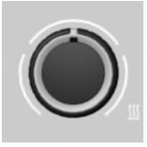 Turn the ring to set the desired temperature.
Do not rapidly switch between different temperature settings. Otherwise, the automatic climate control will not have sufficient time to adjust the set temperature.
Air conditioning
Concept
The air in the car's interior will be cooled and dehumidified and, depending on the temperature setting, warmed again.
The car's interior can only be cooled with the engine running.
Switching on/off
 Press button.
The LED is illuminated with air conditioning switched on.
Depending on the weather, the windshield and side windows may fog up briefly when the engine is started.
The air conditioner produces condensation water, refer to page 227, that will exit from below the vehicle.
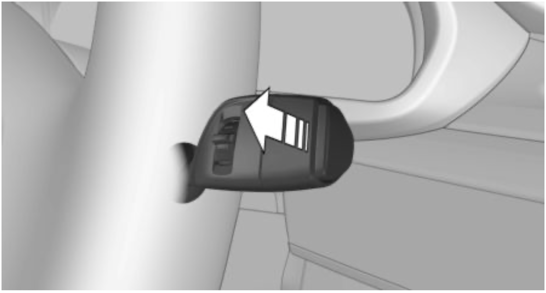
Recirculated-air mode
Concept
You may react to unpleasant odors or pollutants in the immediate environment by temporarily suspending the supply of outside air. The system then recirculates the air flow within the vehicle.
Operation
 Press button repeatedly to select an operating mode:
To prevent window fogging, recirculated-air mode switches off automatically after a certain amount of time, depending on the environmental conditions.
With constant recirculated-air mode, the air quality in the car's interior deteriorates and the fogging of the windows increases.
If the windows fog over, switch off recirculatedair mode and increase the air flow, if needed.
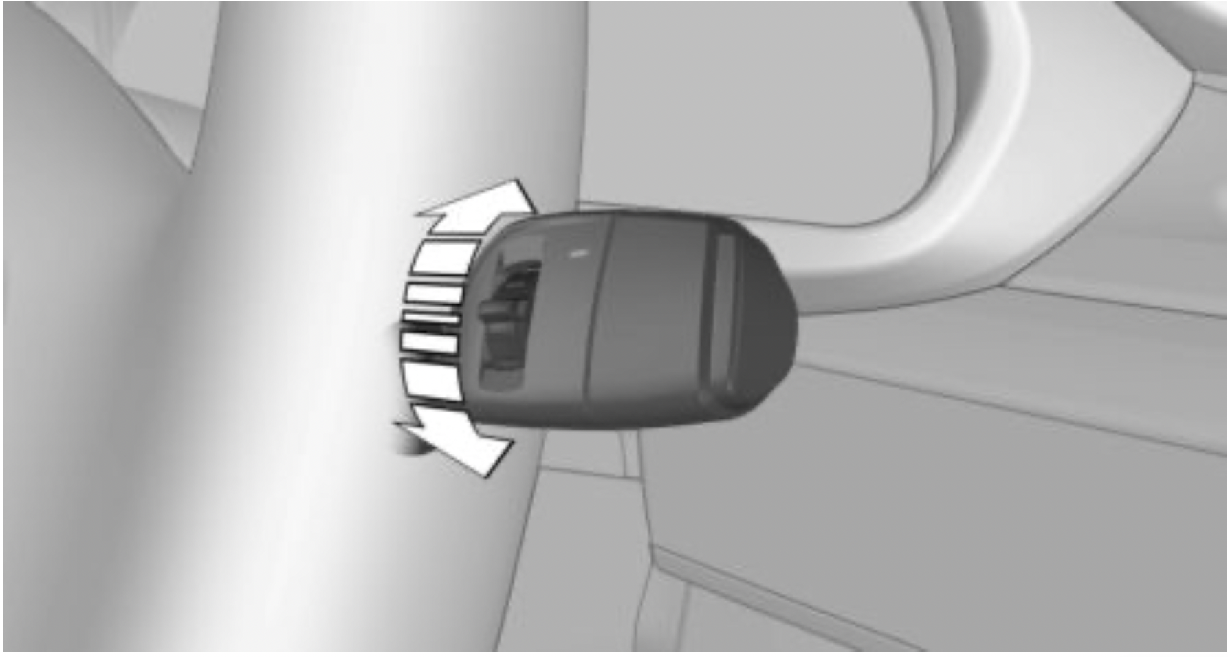
Controlling the air flow manually
Concept
The air flow for climate control can be adjusted manually.
Operation
 Press the left or right side of the button: decrease or increase air flow.
The intensity is indicated by LEDs. The highest level is active when seven LEDs are lit.
The air flow from the air conditioner may be reduced automatically to save battery power.
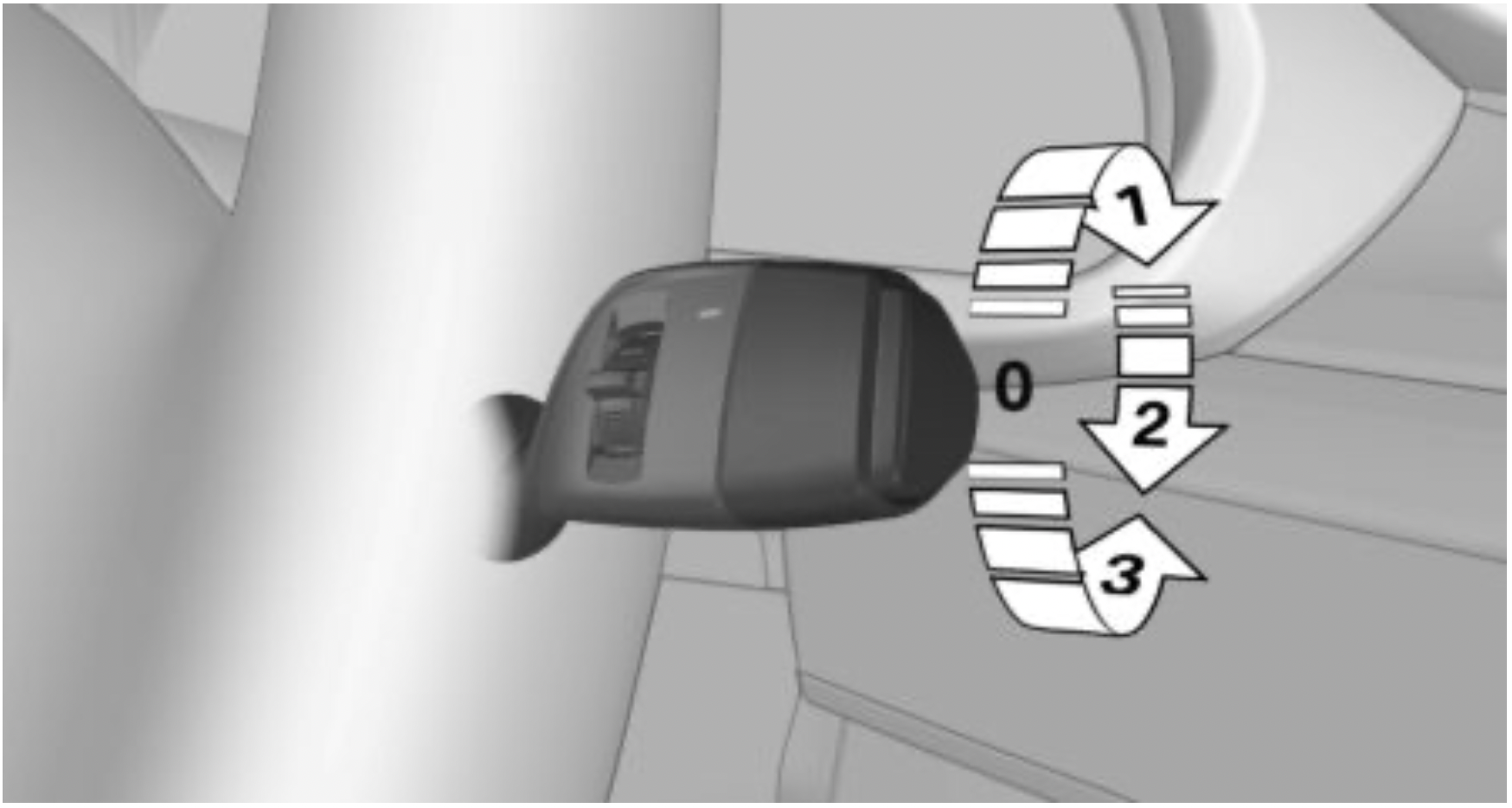
Controlling the air distribution manually
Concept
The air distribution for climate control can be adjusted manually.
Operation

Turn the wheel to select the desired program or the desired intermediate setting.
 Windows.
 Upper body region.
 Floor area.
 Windows, upper body region, and floor area.
Defrosting windows and removing condensation
Make the following settings to defrost the windows and remove condensation:
Rear window defroster
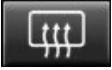 Press button. The LED lights up.
The rear window defroster switches off automatically after a certain period of time.
For permanent activation, press the button for longer than 3 seconds. To deactivate, press the button again.
The rear window defroster can only be activated continuously at an external temperature below approx. 23 ℉/–5 ℃.
Microfilter
In external and recirculated-air mode the microfilter filters dust and pollen from the air.
Have this filter changed during vehicle maintenance, refer to page 271.
Climate control functions in detail
Switching the system on/off
Switching on
Press any button except for the following:
Switching off
 Press button.
Temperature
Concept
The automatic climate control achieves the set temperature as quickly as possible, if necessary by using the maximum cooling or heating power, and then keeps it constant.
Settings
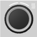 Turn the ring to set the desired temperature.
The selected temperature is shown on the display of the automatic climate control.
The automatic climate control reaches this temperature as quickly as possible, if needed, by increasing the cooling or heating output, and then keeps it constant.
Do not rapidly switch between different temperature settings. Otherwise, the automatic climate control will not have sufficient time to adjust the set temperature.
Air conditioning
Concept
The air in the car's interior will be cooled and dehumidified and, depending on the temperature setting, warmed again.
The car's interior can only be cooled with the engine running.
Switching on/off
 Press button.
The LED is illuminated with air conditioning switched on.
Depending on the weather, the windshield and side windows may fog up briefly when the engine is started.
The air conditioning is switched on automatically with the AUTO program.
When using the automatic climate control, condensation water, refer to page 227, develops and drains underneath the vehicle. This is normal.
Maximum cooling
Concept
The system is set to the lowest temperature, optimum air flow and recirculated-air mode.
General information
The function is available above an external temperature of approx. 32 ℉/0 ℃ And with the engine running.
Switching on/off
 Press button.
The LED is illuminated with the system switched on.
Air flows out of the vents to the upper body region. The vents need to be open for this.
The air flow can be adjusted with the air flow active.
AUTO program
Concept
Air flow, air distribution and temperature are controlled automatically.
Switching on/off
 Press button.
The LED is illuminated with the AUTO program switched on.
Depending on the selected temperature, the intensity of the AUTO program, and outside influences, the air is directed to the windshield, side windows, upper body, and into the floor area.
The air conditioning, refer to page 202, is switched on automatically with the AUTO program.
At the same time, a condensation sensor controls the program so as to prevent window condensation as much as possible.
Intensity
With the AUTO program switched on, the intensity can be set. This changes the automatic control for the air flow and air distribution.
 Press the left or right side of the button: decrease or increase intensity.
The selected intensity is shown on the display of the automatic climate control.
Automatic recirculated-air control/ recirculated-air mode
Concept
The automatic recirculated-air control AUC recognizes odors or pollutants in the outside air. The outside air supply is shut off and the interior air is recirculated.
General information
If the system is activated, a sensor detects pollutants in the outside air and controls the shut-off automatically.
If the system is deactivated, outside air continuously flows into the car's interior.
With constant recirculated-air mode, the air quality in the car's interior deteriorates and the fogging of the windows increases.
Switching on/off
 Press button repeatedly to select an operating mode:
Recirculated-air mode switches off automatically at low external temperatures after a certain amount of time in order to avoid window fogging.
If the windows are fogged over, switch off the recirculated-air mode and press the AUTO button to utilize the condensation sensor. Make sure that air can flow to the windshield.
Controlling the air flow manually
Concept
The air flow for climate control can be adjusted manually.
General information
To manually adjust air flow switch off AUTO program first.
Operation
 Press the left or right side of the button: decrease or increase air flow.
The selected air flow is shown on the display of the automatic climate control.
The air flow of the automatic climate control may be reduced automatically to save battery power.
Controlling the air distribution manually
Concept
The air distribution for climate control can be adjusted manually.
Operation
 Press button repeatedly to select a program:
If the windows are fogged over, press the AUTO button to utilize the condensation sensor.
SYNC program
Concept
The system enables the transfer of current settings on the driver's side for temperature, air flow, air distribution, and the AUTO program to the front passenger side and to the left and right rear.
Switching on/off
 Press button.
The current setting of the temperature on the driver's side is transferred to the front passenger side.
The program is switched off if the setting on the front passenger side is changed.
Defrosting windows and removing condensation
Concept
Ice and condensation are quickly removed from the windshield and the front side windows.
Switching on/off
 Press button.
The LED is illuminated with the system switched on.
For this purpose, point the side vents towards the side windows as needed.
The air flow can be adjusted with the air flow active.
If the windows are fogged over, you can also switch on the air conditioning or press the AUTO button to utilize the condensation sensor.
Rear window defroster
 Press button. The LED lights up.
The rear window defroster switches off automatically after a certain period of time.
For permanent activation, press the button for longer than 3 seconds. To deactivate, press the button again.
The rear window defroster can only be activated continuously at an external temperature below approx. 23 ℉/–5 ℃.
Microfilter/activated-charcoal filter
In external and recirculated-air mode the microfilter/activated charcoal filter filters dust, pollen, and gaseous pollutants out of the air.
Have this filter changed during vehicle maintenance, refer to page 271.
Front ventilation
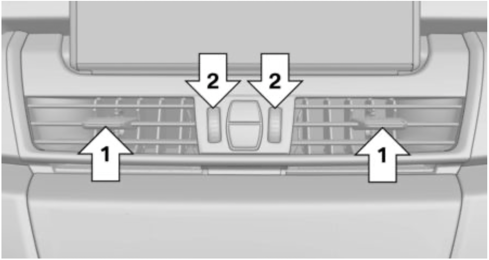
Settings
Ventilation in the rear
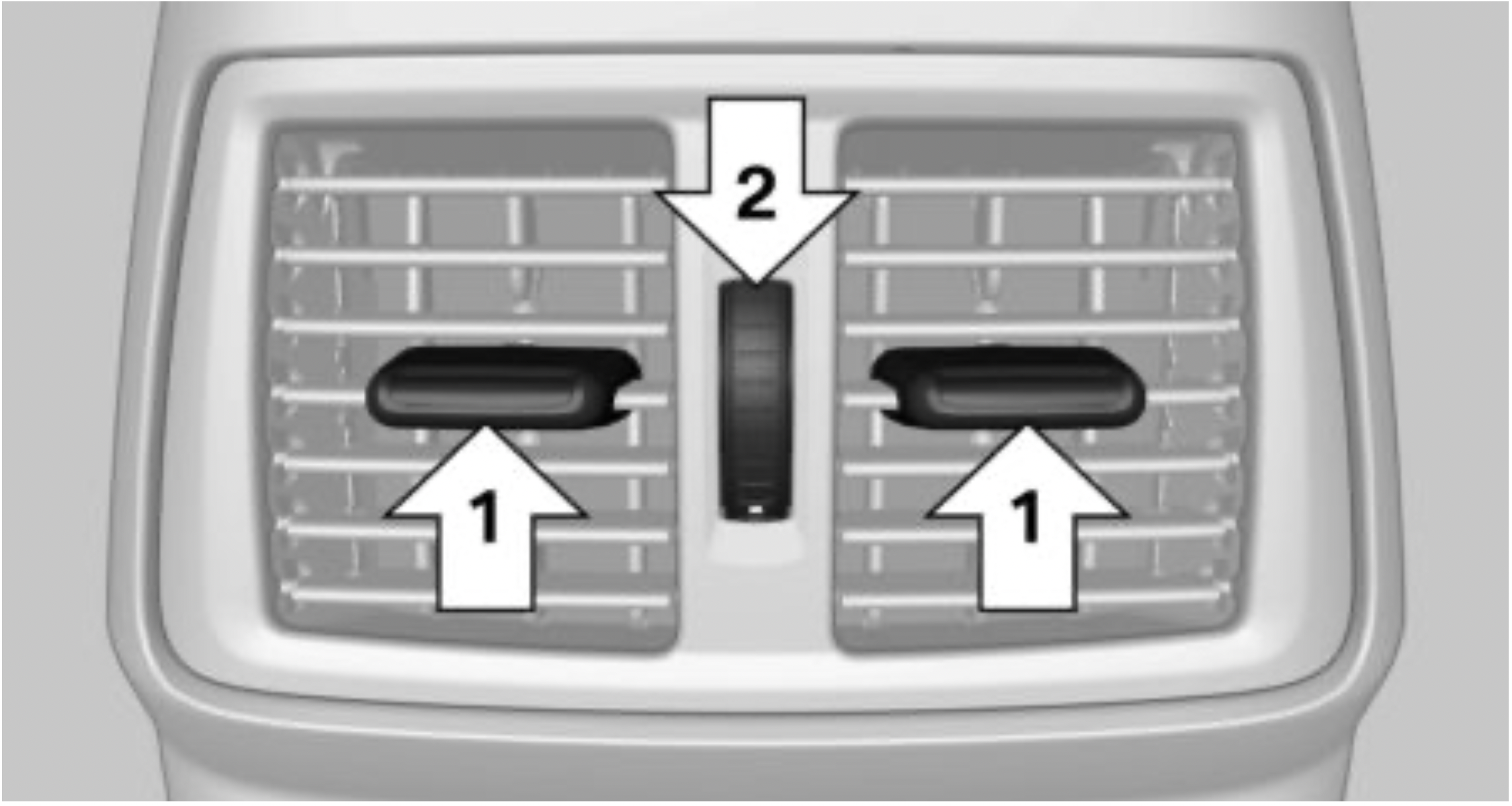
Concept
The parked-car ventilation ventilates the car's interior and lowers its temperature, if needed.
General information
The parked-car ventilation can be switched on and off directly or by using two preset activation times. The system remains switched on for 30 minutes.
The parked-car ventilation system is operated via iDrive.
Functional requirements
Switching on/off directly
Via iDrive:
 The symbol on the automatic climate control flashes if the system is switched on.
Preselecting the activation time
Via iDrive:
Activating the activation time
Via iDrive:
 The symbol on the automatic climate control lights up when the activation time is activated.
 The symbol on the automatic climate control flashes when the system has been switched on.
The system will only be switched on within the next 24 hours. After that, it needs to be reactivated.
This chapter describes all standard, country-specific and optional features offered with the series. It also describes features that are not necessarily available in your vehicle, e. g., due to the selected options or country versions. This also applies to safety-related functions and systems. When using these functions and systems, the applicable laws and regulations must be observed.
The maintenance system indicates required maintenance measures, and thereby provides support in maintaining road safety and the operational reliability of the vehicle.
In some cases, scopes and intervals of the maintenance system may vary according to the country version. Replacement work, spare parts, fuels and lubricants, and wear materials are calculated separately. Further information is available from a dealer’s service center or another qualified service center or repair shop.
Concept
Sensors and special algorithms take into account the driving conditions of the vehicle. CBS uses these to calculate the need for maintenance.
The system makes it possible to adapt the amount of maintenance corresponding to your user profile.
General information
Information on service requirements, refer to page 135, can be displayed on the Control Display.
Service data in the remote control
Information on the required maintenance is continuously stored in the remote control. The dealer’s service center can read this data out and suggest a maintenance scope for the vehicle.
Therefore, hand the service advisor the remote control with which the vehicle was driven most recently.
Storage periods
Storage periods during which the vehicle battery was disconnected are not taken into account.
If this occurs, have a dealer's service center or another qualified service center or repair shop update the time-dependent maintenance procedures, such as checking brake fluid and, if necessary, changing the engine oil and the microfilter/ activated-charcoal filter.
Please consult your Service and Warranty Information Booklet for US models and Warranty and Service Guide Booklet for Canadian models for additional information on service requirements.
The manufacturer of your vehicle recommends that maintenance and repair be performed by a dealer’s service center or another qualified service center or repair shop. Records of regular maintenance and repair work should be retained.
General information
Devices connected at the OBD socket trigger the alarm system when the vehicle is locked. Remove any devices connected at the OBD socket before locking the vehicle.
Safety information
NOTE: The socket for Onboard Diagnosis is an intricate component intended to be used in conjunction with specialized equipment to check the vehicle’s primary emissions system. Improper use of the socket for Onboard Diagnosis, or contact with the socket for Onboard Diagnosis for other than its intended purpose, can cause vehicle malfunctions and creates risks of personal and property damage. Given the foregoing, the manufacture of your vehicle strongly recommends that access to the socket for Onboard Diagnosis be limited to a dealer's service center or another qualified service center or repair shop or other persons that have the specialized training and equipment for purposes of properly utilizing the socket for Onboard Diagnosis.
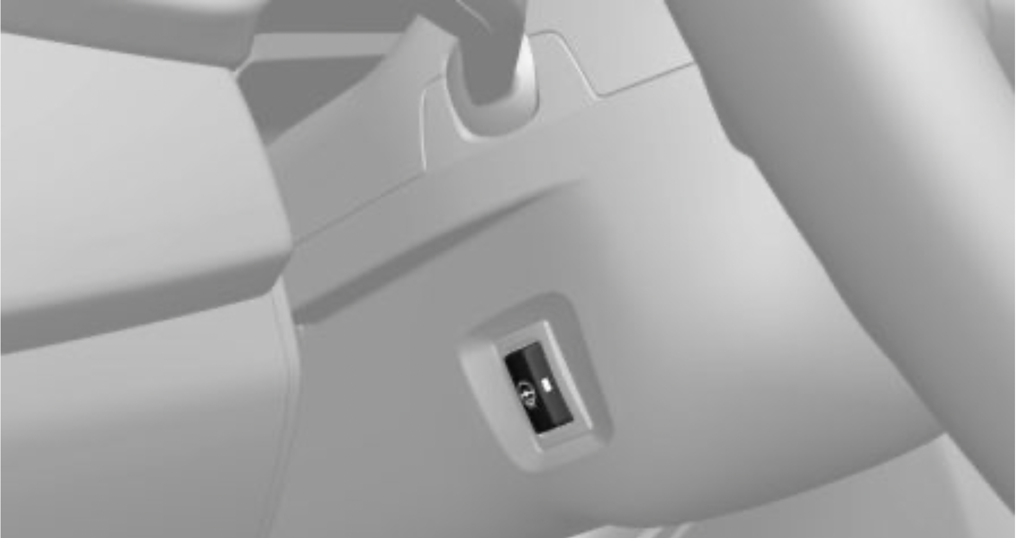
Position
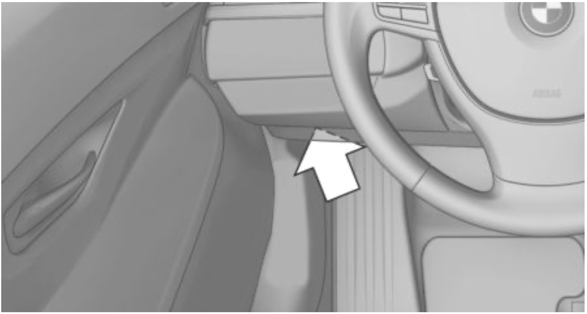
There is an OBD socket on the driver's side for checking the primary components in the vehicle's emissions.
Emissions

This chapter describes all standard, country-specific and optional features offered with the series. It also describes features that are not necessarily available in your vehicle, e. g., due to the selected options or country versions. This also applies to safety-related functions and systems. When using these functions and systems, the applicable laws and regulations must be observed.
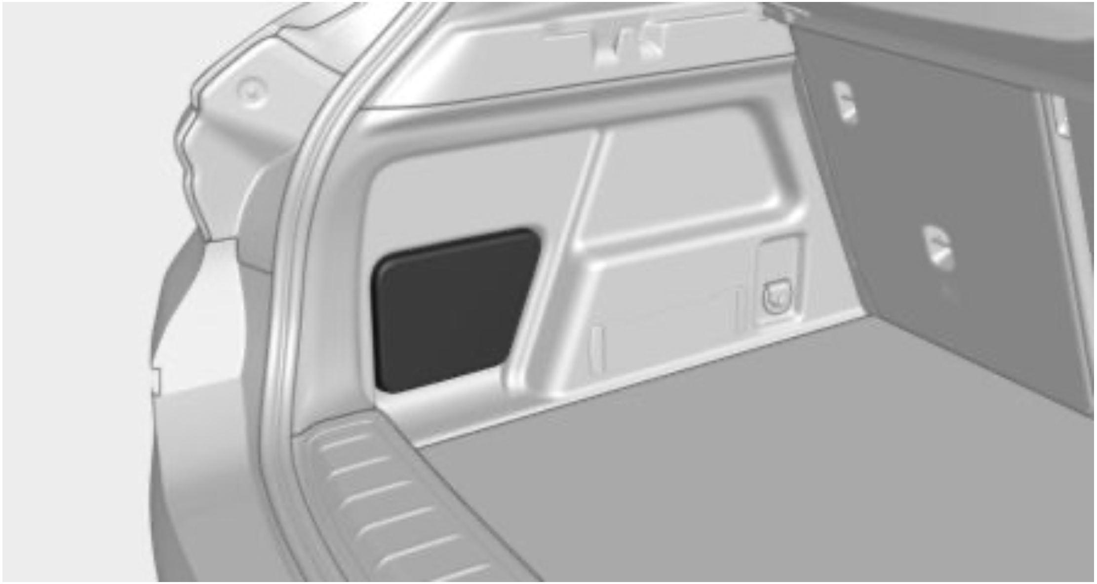
Depending on the vehicle equipment, the onboard vehicle tool kit is located:
Safety information
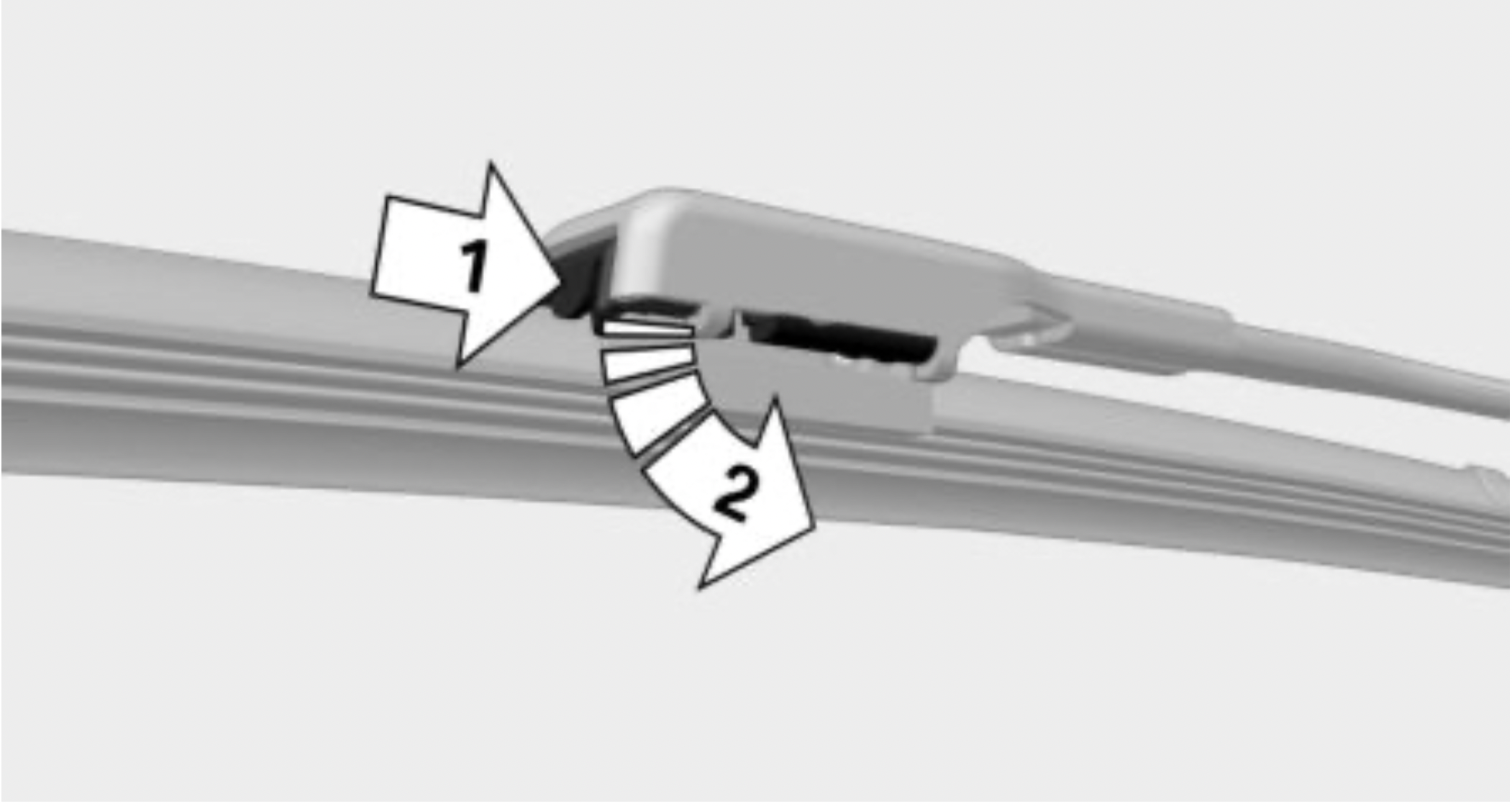
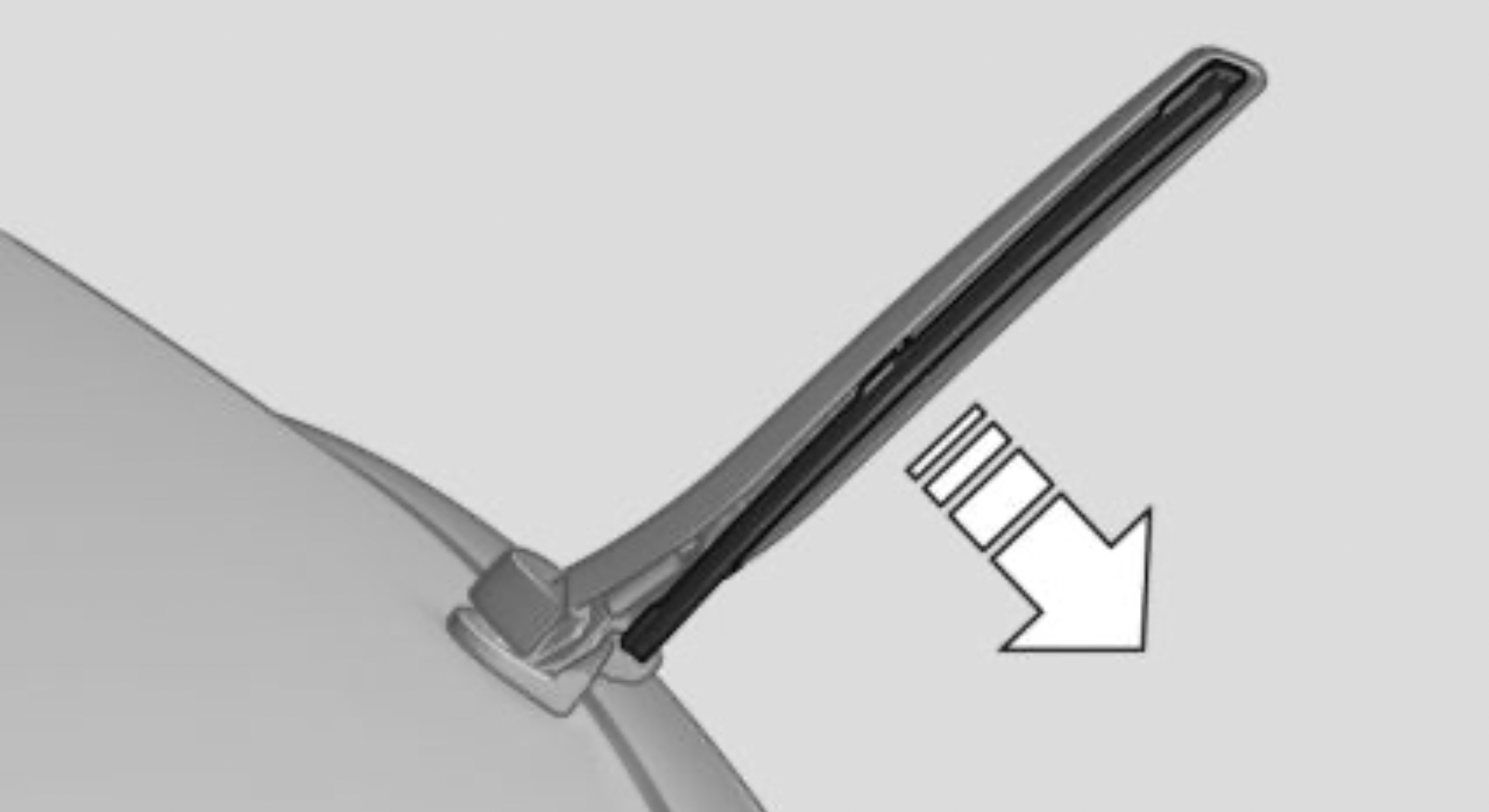
NOTE: The window may sustain damage if the wiper falls onto it without the wiper blade installed. There is a risk of damage to property. Hold the wiper firmly when changing the wiper blade. Do not fold or switch on the wiper without a wiper blade installed.
NOTE: Folded-away wipers can be jammed when the hood is opened. There is a risk of damage to property. Make sure that the wipers with the wiper blades mounted are folded down onto the windshield before opening the hood.
Replacing the front wiper blades
Replacing the rear wiper blade
General information
Lights and bulbs
Lights and bulbs make an essential contribution to vehicle safety.
The vehicle manufacturer recommends that you have the relevant work carried out a dealer’s service center or another qualified service center or repair shop.
A spare light box is available from a dealer’s service center or another qualified service center or repair shop.
Follow the safety information, refer to page 274.
Light-emitting diodes (LEDs)
Some items of equipment use light-emitting diodes installed behind a cover as a light source. These light-emitting diodes are related to conventional lasers and are officially designated as Class 1 light-emitting diodes.
Follow the safety information, refer to page 274.
Safety information
Lights and bulbs
WARNING: Bulbs can get hot during operation. Contact with the bulbs can cause burns. There is a risk of injury. Only change bulbs after they have cooled off.
WARNING: Work on switched-on lighting systems can cause short circuits. There is a risk of injury or risk of damage to property. When working on the lighting system, switch off the lights in question. If necessary, heed the bulb manufacturer's instructions.
NOTE: Dirty bulbs have a reduced service life. There is a risk of damage to property. Do not hold new bulbs with your bare hands. Use a clean cloth or something similar, or hold the bulb by its base.
Light-emitting diodes (LEDs)
WARNING: Intensive brightness can irritate or damage the retina of the eye. There is a risk of injury. Do not look directly into the headlights or other light sources. Do not remove the LED covers.
Headlight glass
Condensation can form on the inside of the external lights in cool or humid weather. When driving with the lights switched on, the condensation evaporates after a short time. The headlight glass does not need to be changed.
If despite driving with the headlights switched on, increasing humidity forms, for instance water droplets in the light, have the headlights checked.
Headlight setting
The headlight adjustments can be affected by changing lights and bulbs. After the headlight adjustment was changed, have it checked and, if necessary, corrected by a dealer’s service center or another qualified service center or repair shop.
Front lights, bulb replacement
Halogen headlights
Overview
Parking lights, daytime running lights
The parking lights and daytime running lights are made using LED technology.
In the case of a malfunction, contact a dealer’s service center or another qualified service center or repair shop.
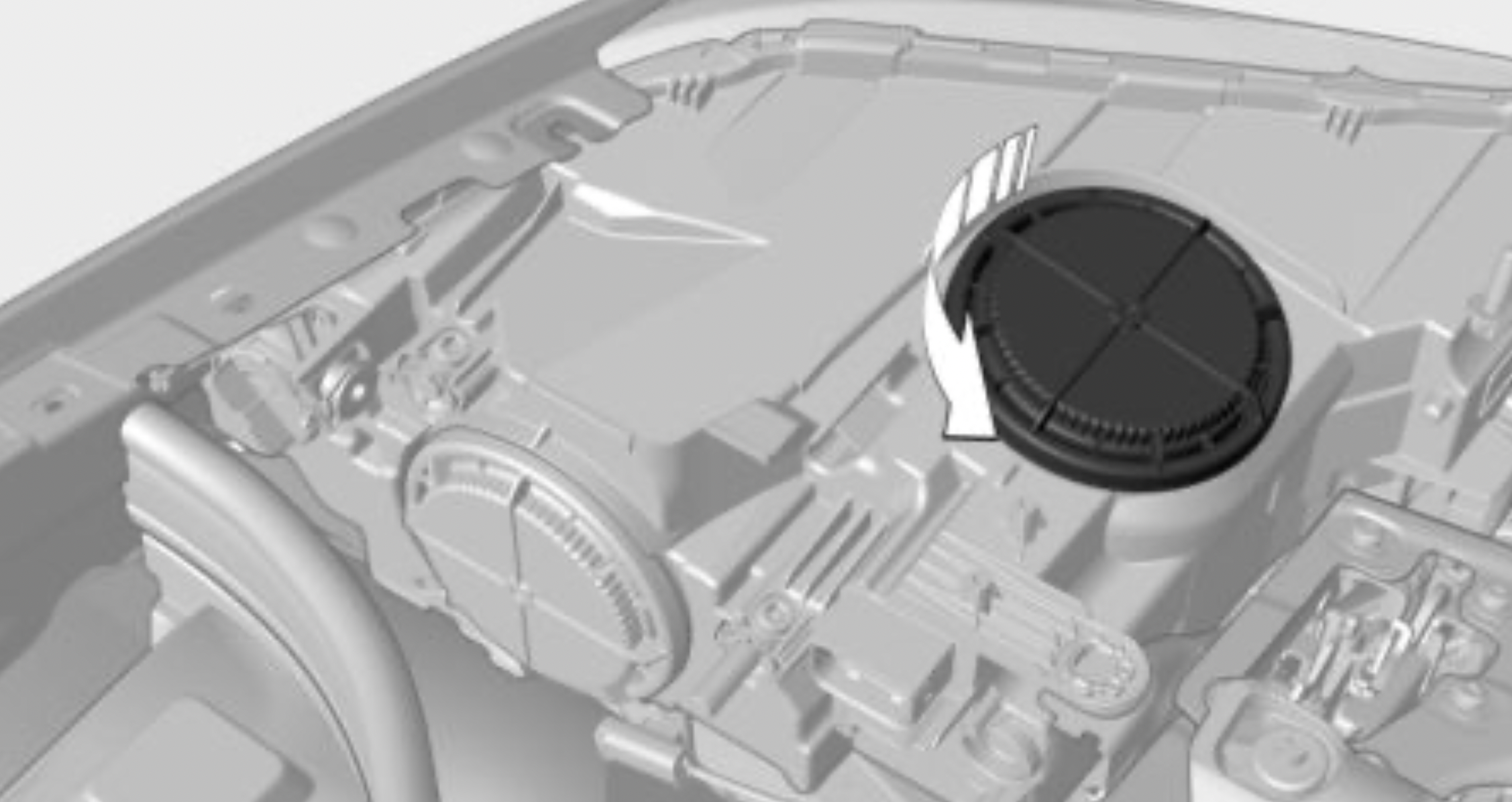
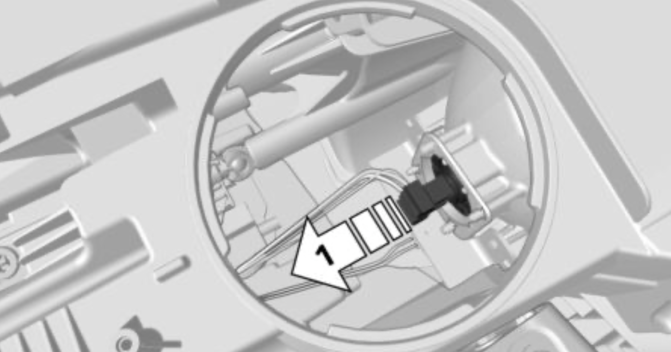
Accessing the turn signals, low beams, high beams/headlight flasher
Follow the safety information, refer to page 274. Open the hood, refer to page 263.
Turn signal
3457nak bulb

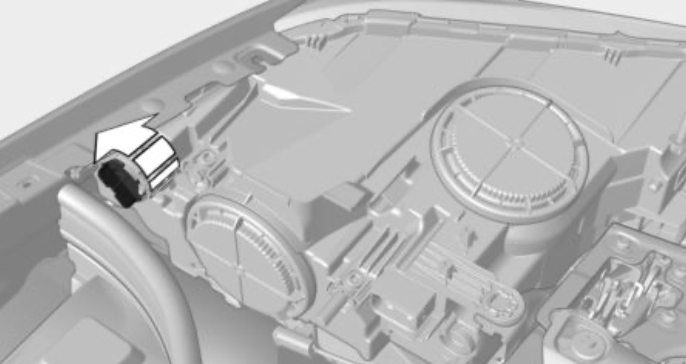
Low beams
55 watt bulb, H7LL.
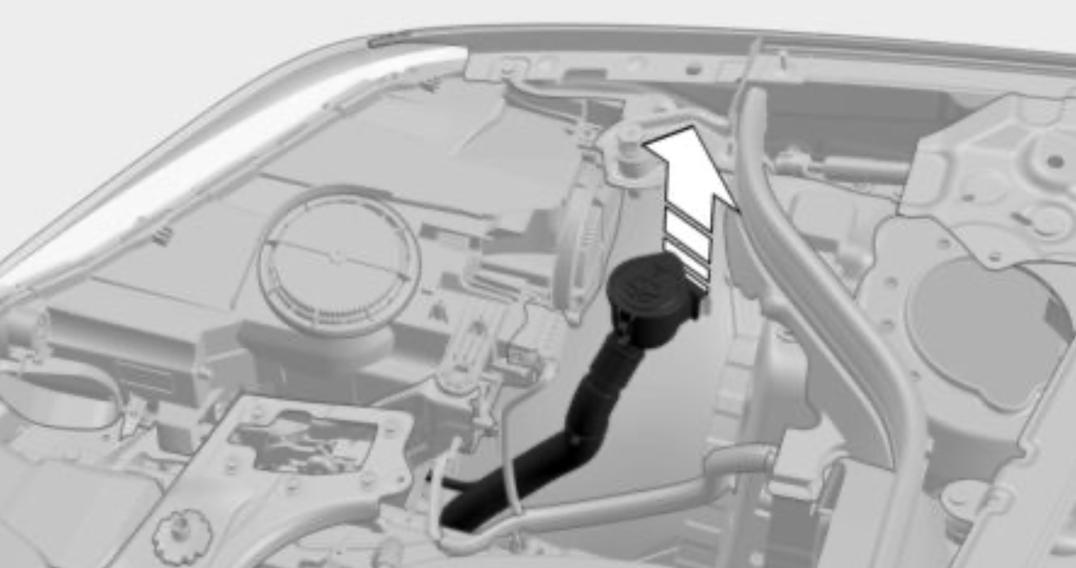
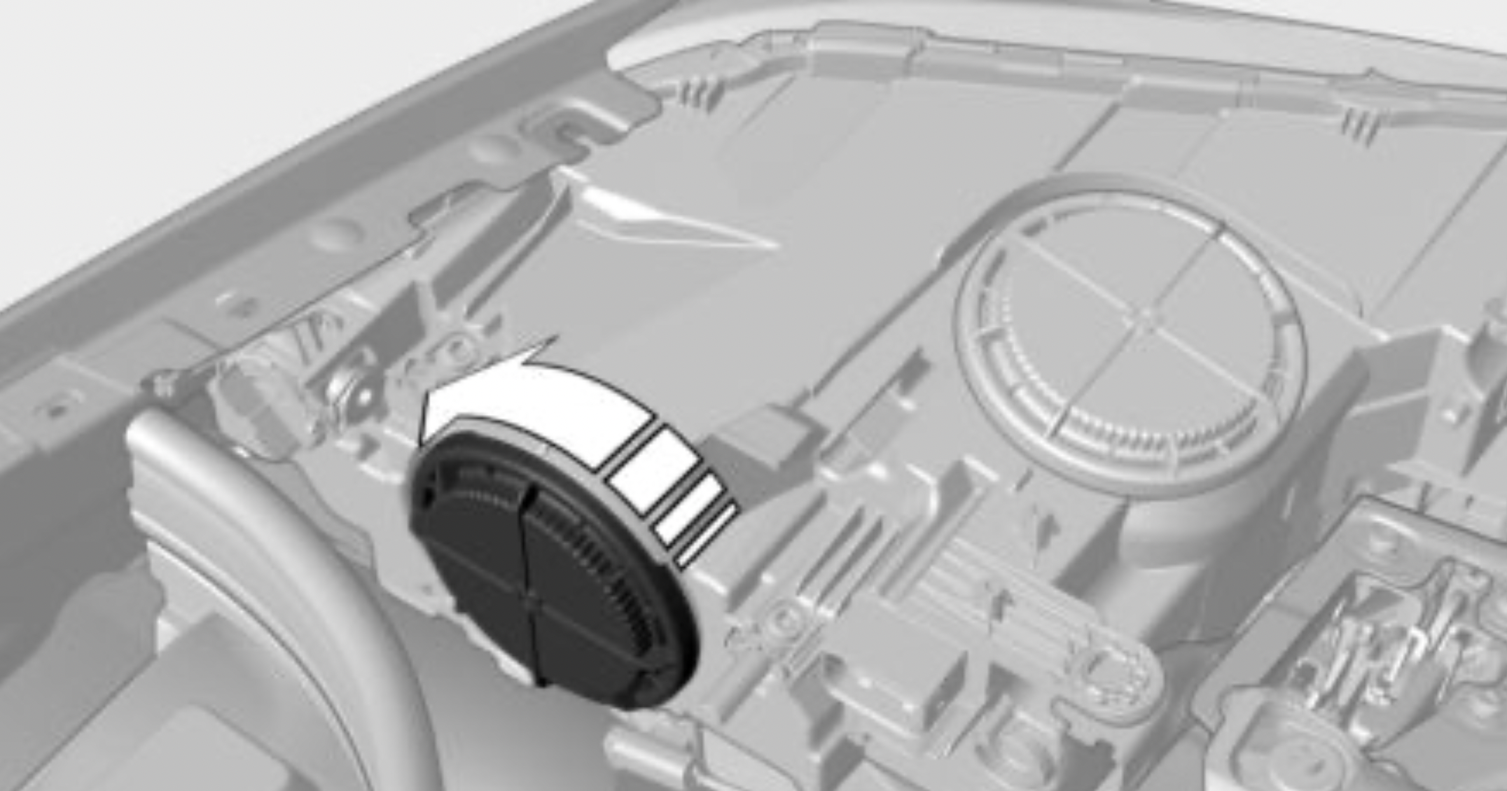
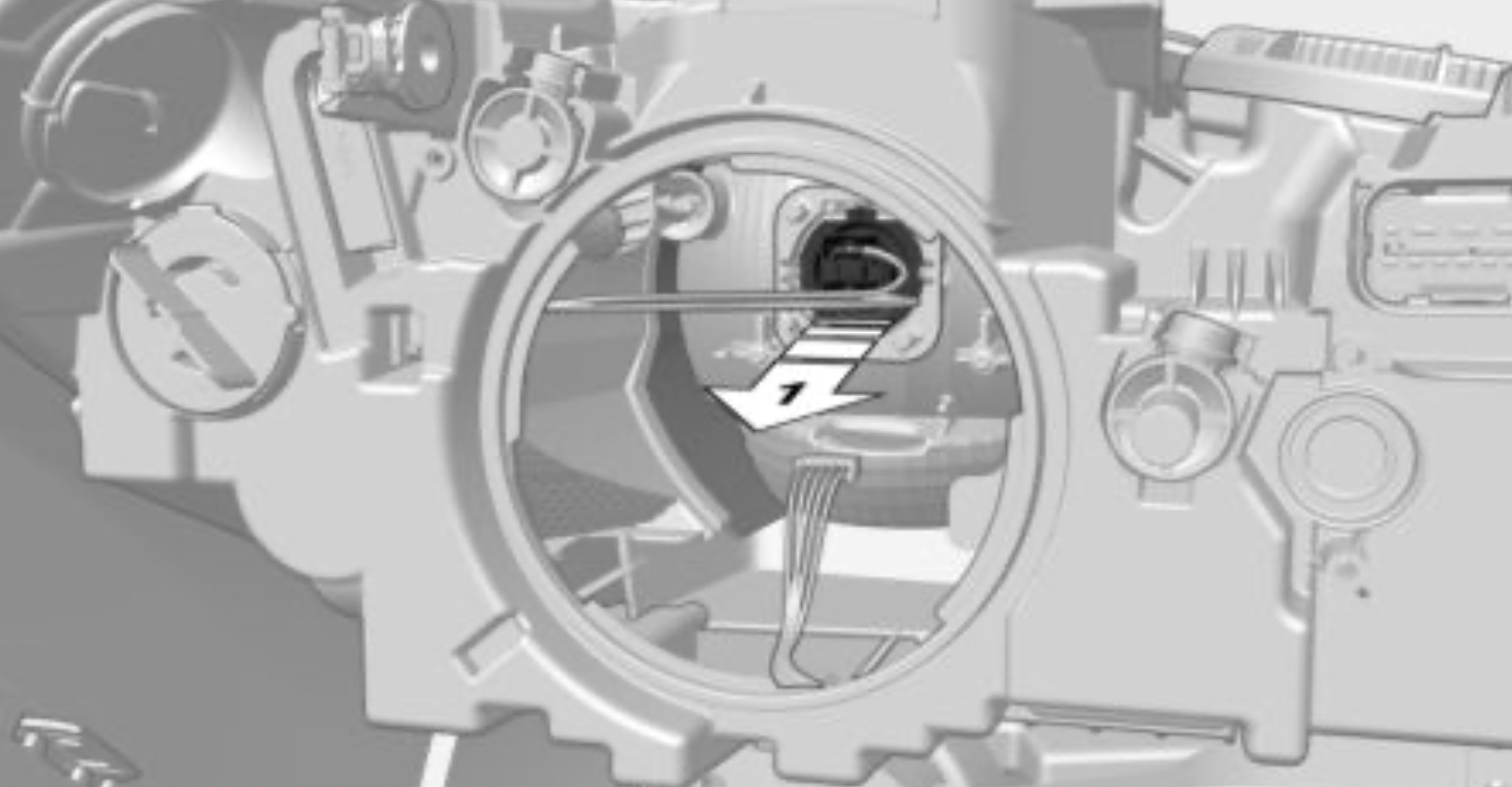
High beams/headlight flasher
55-watt bulb, H7.
LED headlights
Overview
Front lights
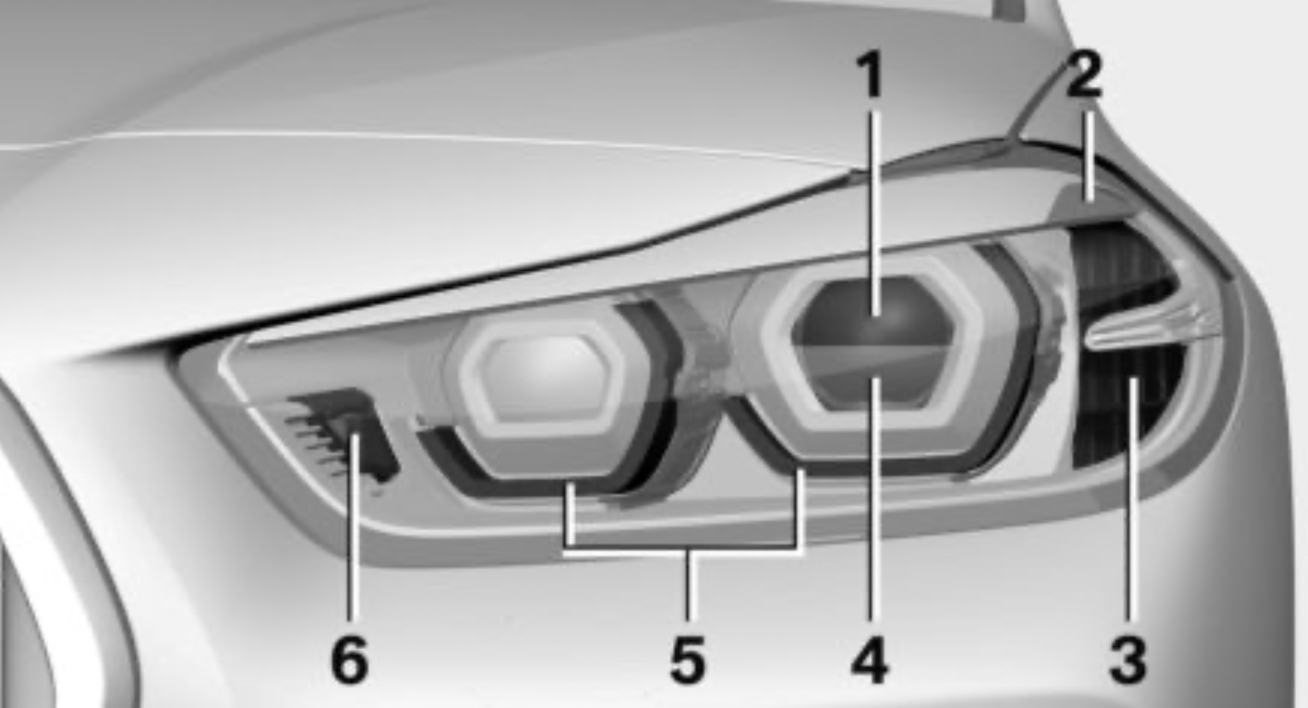
The following lights feature LED technology:
In the case of a malfunction, contact a dealer’s service center or another qualified service center or repair shop.
LED front fog lights
Follow the safety information, refer to page 274. LED front fog lights are made using LED technology.
In the case of a malfunction, contact a dealer’s service center or another qualified service center or repair shop.
Halogen front fog lights
Follow the safety information, refer to page 274. 35-watt bulb, H8.
Turn signal in exterior mirror
The turn signals in the exterior mirrors feature LED technology. In the case of a malfunction, contact a dealer’s service center or another qualified service center or repair shop.
Tail lights, bulb replacement
Overview
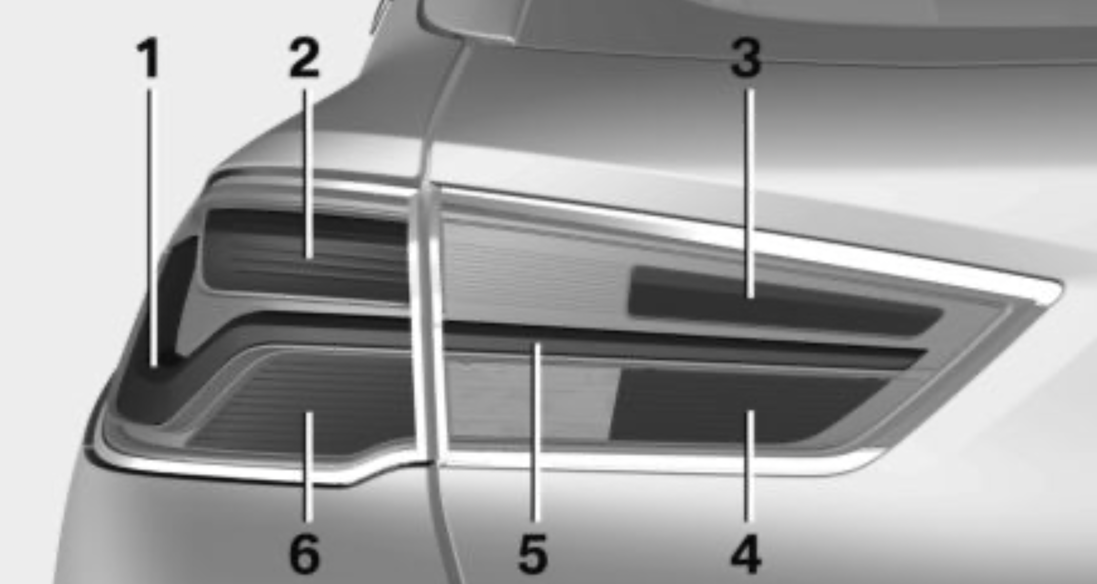
The tail light and brake lights feature LED technology. In the case of a malfunction, contact a dealer’s service center or another qualified service center or repair shop.
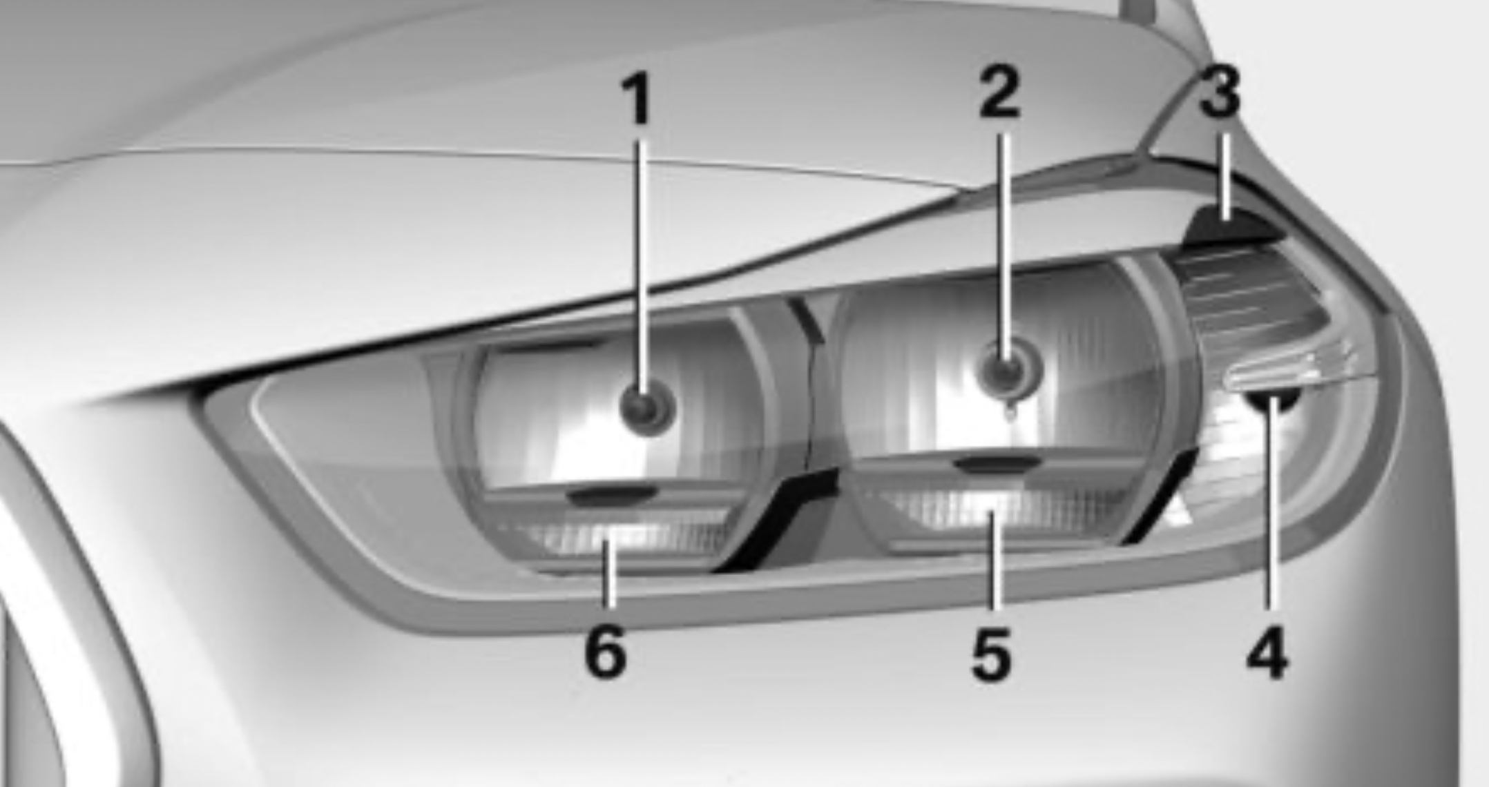
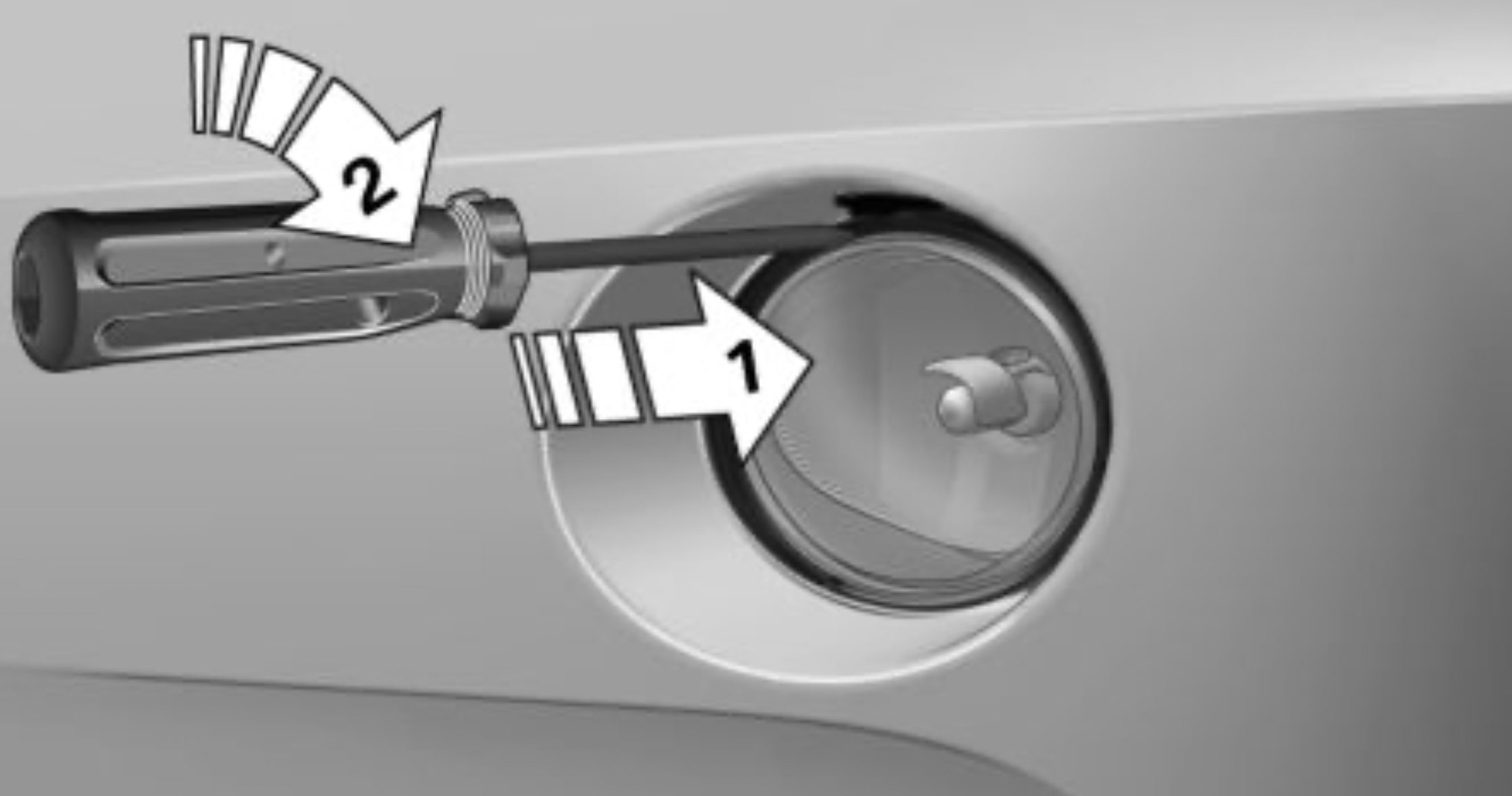
Bulb replacement, exterior tail lights
General information
Follow the safety information, refer to page 274.
Turn signal: 21-watt bulb, P21WLL.
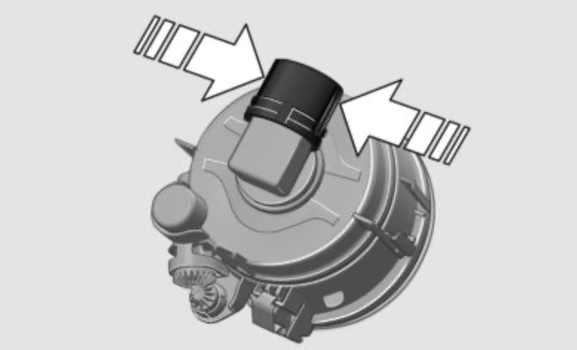
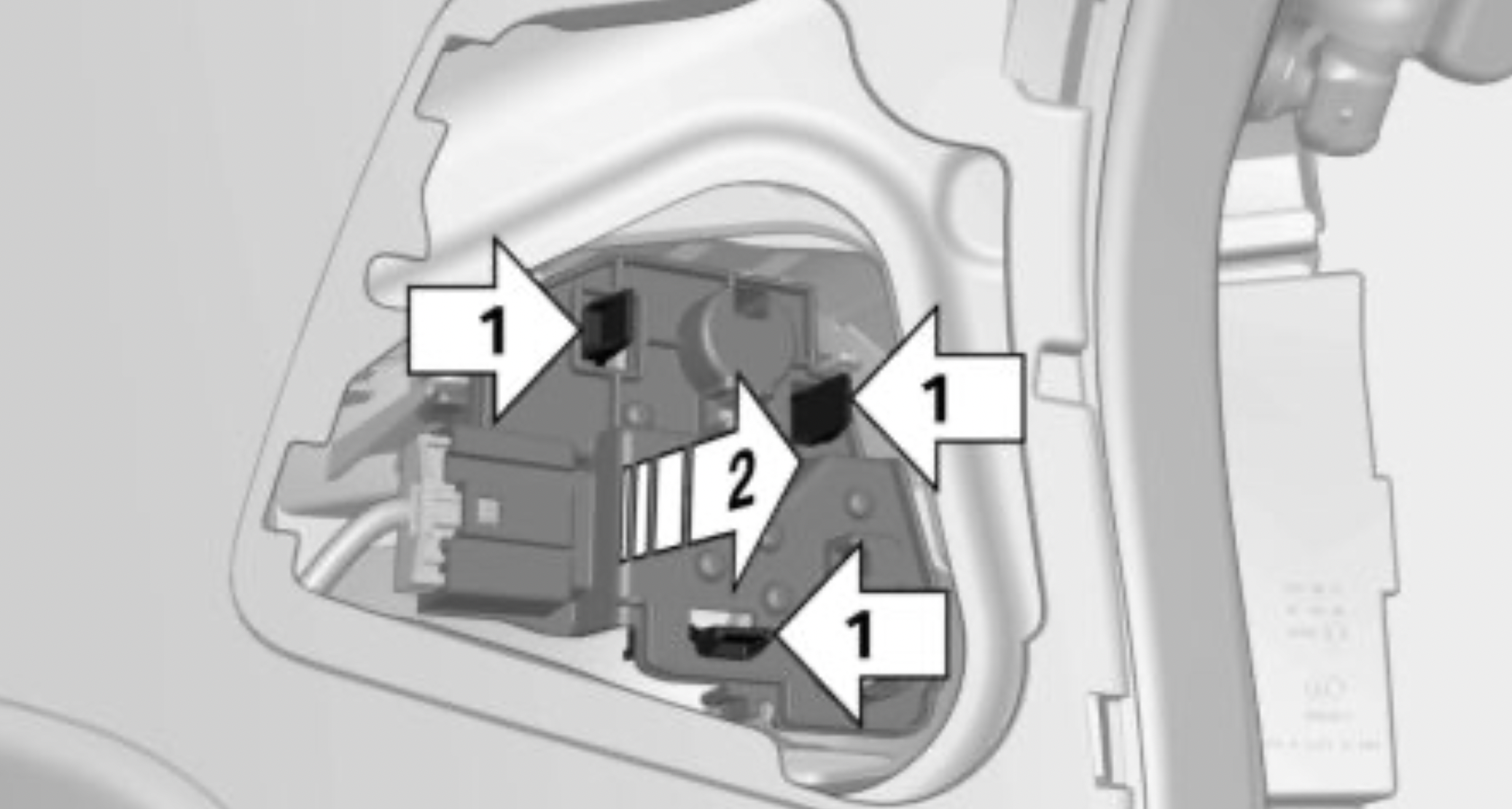
Removing the exterior tail light
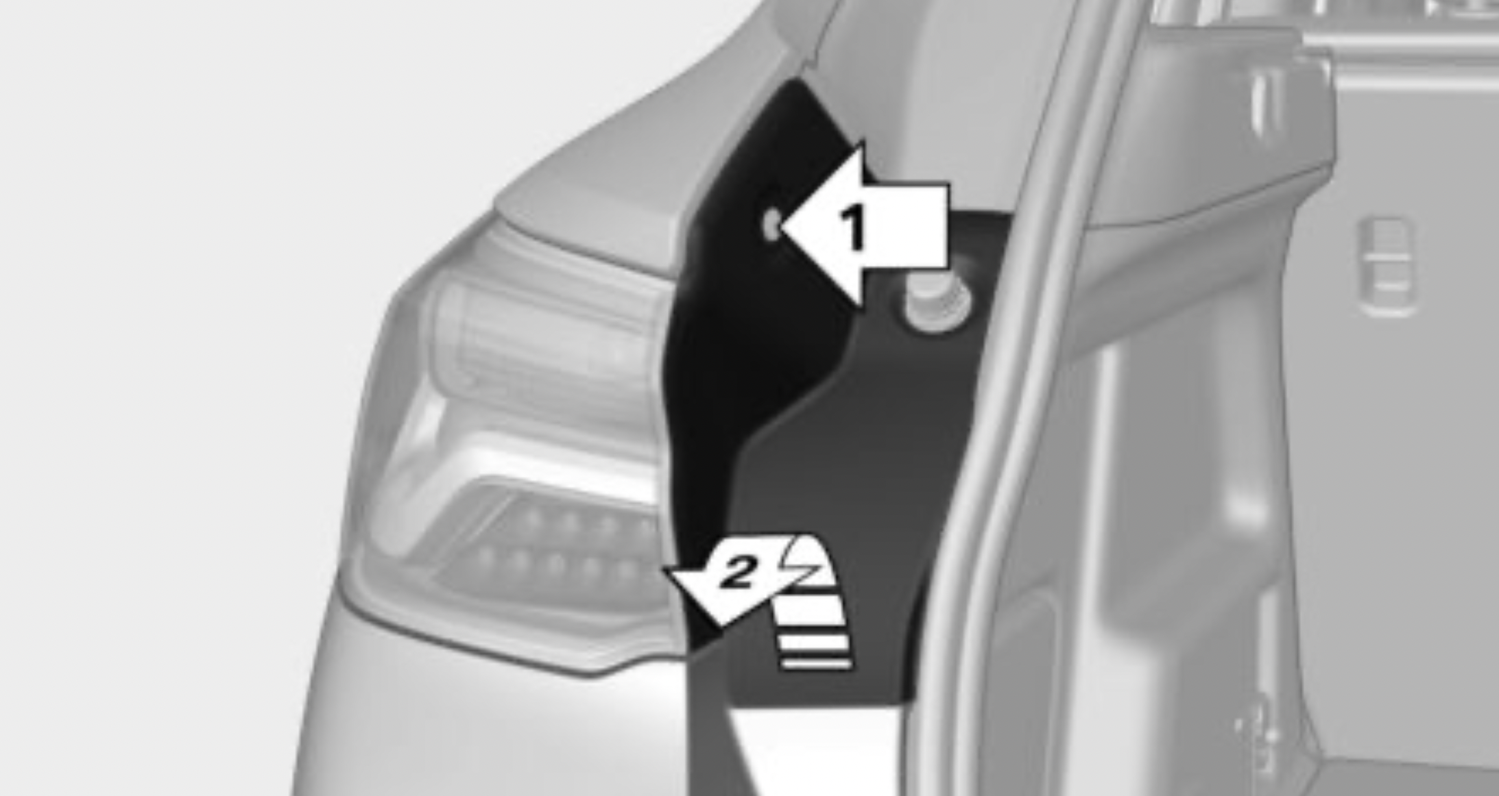
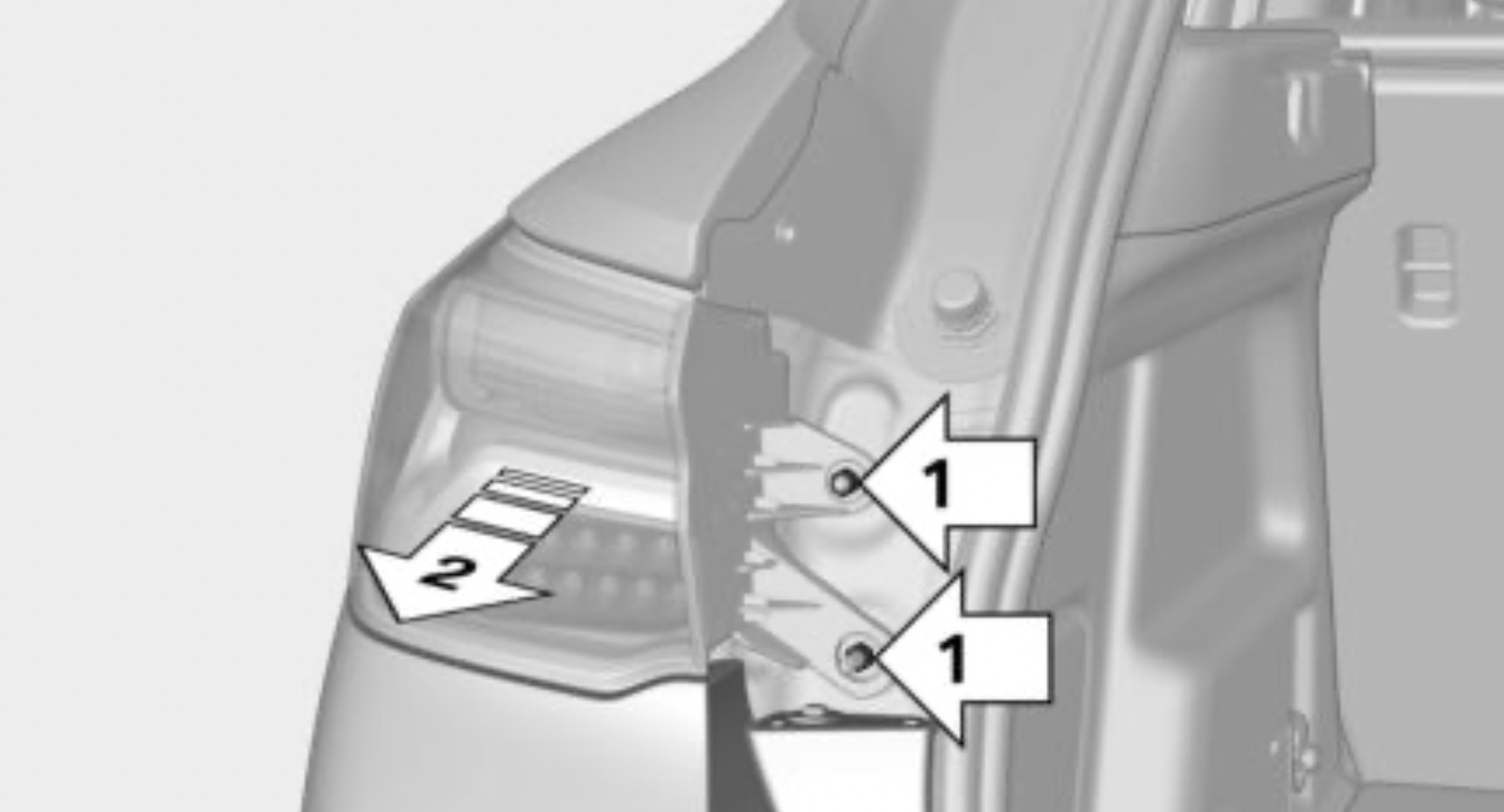
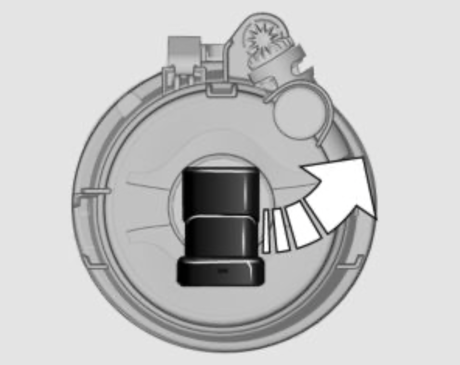
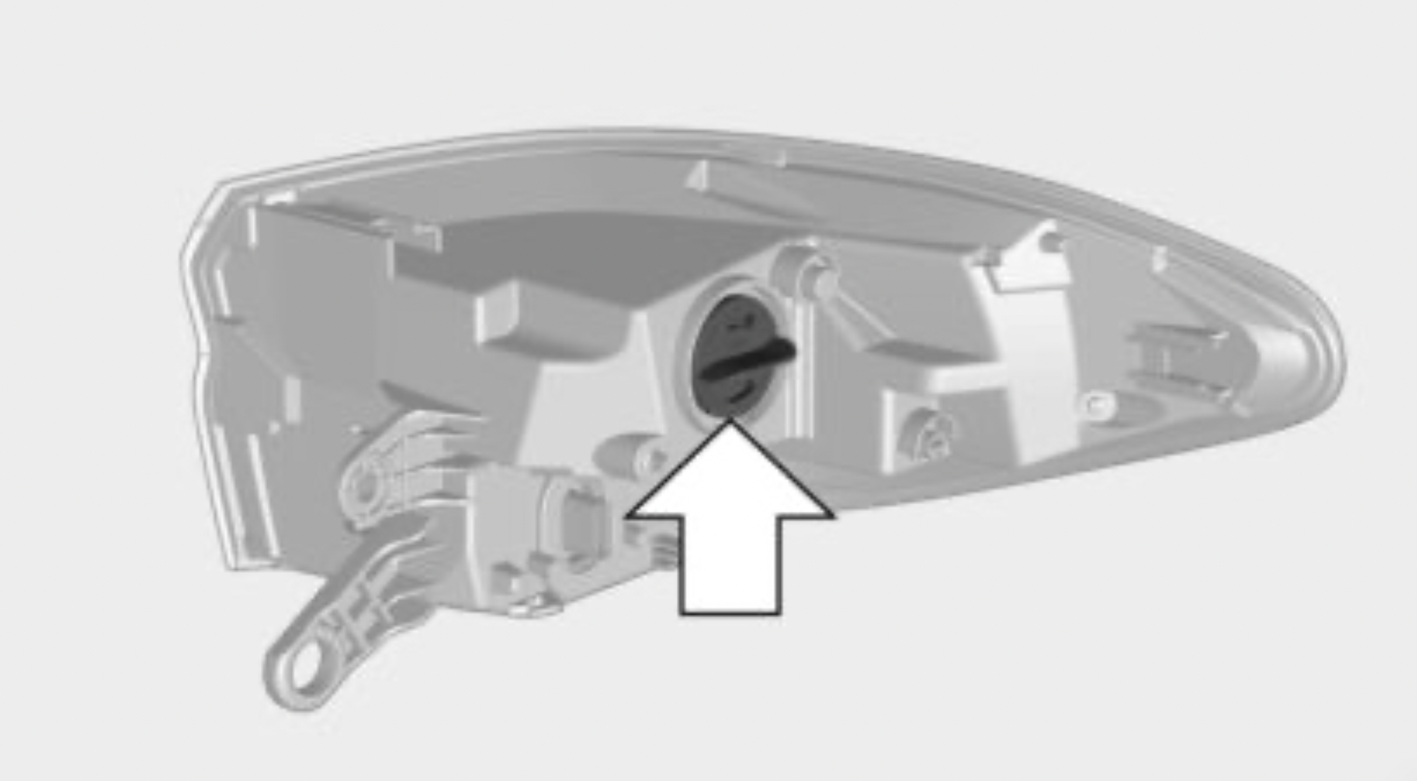
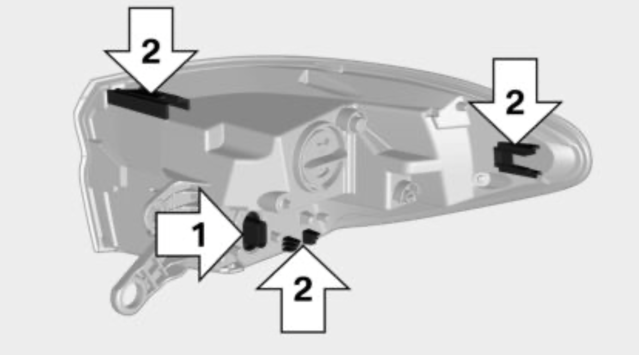
Replacing the bulbs
Installing the tail light
Lights in the tailgate
General
Follow the safety information, refer to page 274. Reversing light: 21-watt bulb, P21WLL Inner brake light: 21-watt bulb, P21WLL
Accessing the lights
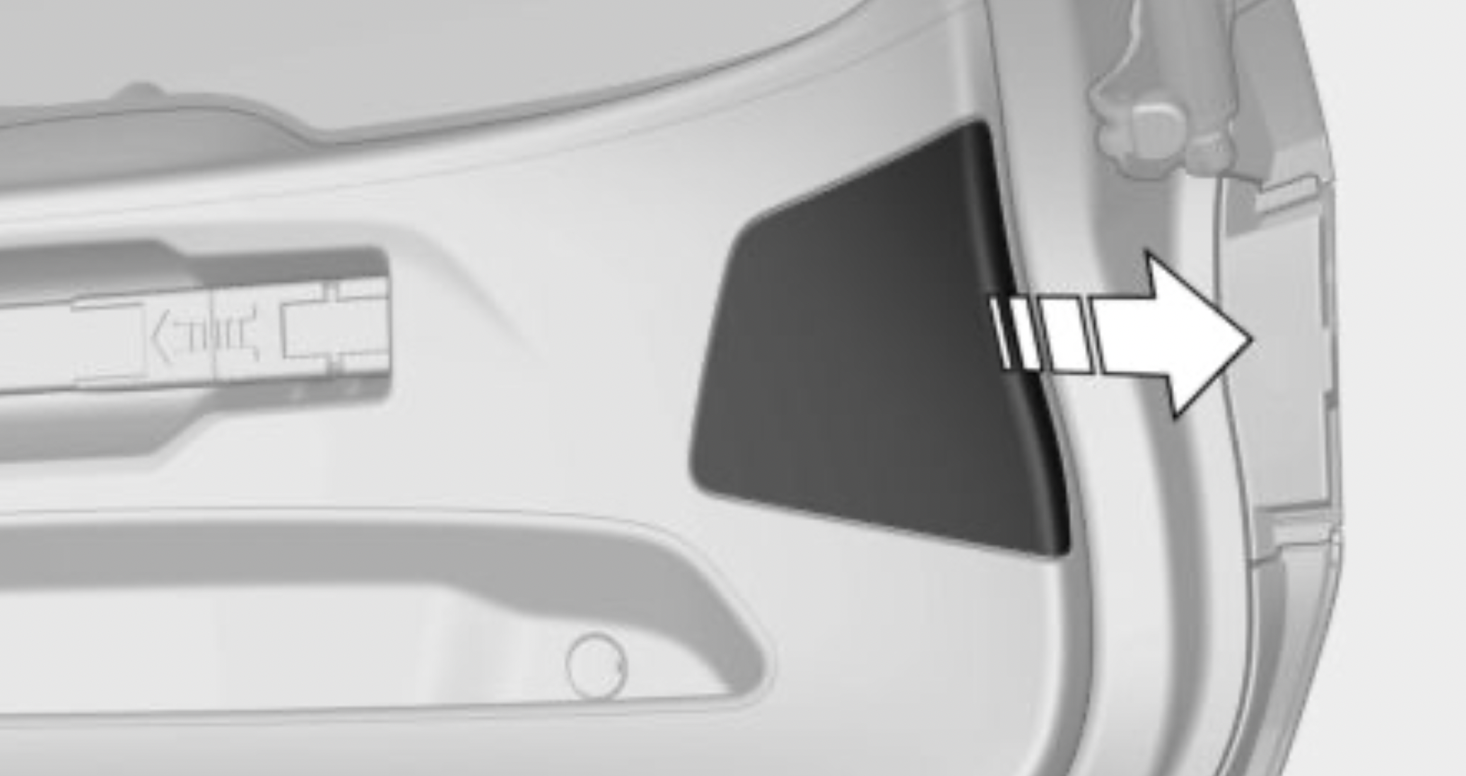
Replacing reversing light and inner brake light
Installing the bulb holder
Central brake light and license plate lights
Follow the safety information, refer to page 274.
These lights are made using LED technology. In the case of a malfunction, contact a dealer’s service center or another qualified service center or repair shop.
Maintenance
The battery is maintenance-free.
The added amount of acid is sufficient for the service life of the battery.
More information about the battery can be requested from a dealer’s service center or another qualified service center or repair shop.
Replacing the vehicle battery
General information
The manufacturer of your vehicle recommends that you have a dealer’s service center or another qualified service center or repair shop register the vehicle battery to the vehicle after the battery has been replaced. Once the battery has been registered again, all comfort features will be available without restriction and any Check Control messages displayed which relate to comfort features will disappear.
Safety information
NOTE: Vehicle batteries that are not compatible can damage vehicle systems and impair vehicle functions. There is a risk of personal and property damage. Only vehicle batteries that are compatible with your vehicle type should be installed in your vehicle. Information on compatible vehicle batteries is available at your dealer’s service center.
Charging the battery
General information
Make sure that the battery is always sufficiently charged to guarantee that the battery remains usable for its full service life.
 A discharged battery is indicated by a red indicator light.
The battery may need to be charged in the following cases:
Safety information
NOTE: Battery chargers for the vehicle battery can work with high voltages and currents, which means that the 12 volt on-board network can be overloaded or damaged. There is a risk of damage to property. Only connect battery chargers for the vehicle battery to the starting aid terminals in the engine compartment.
Starting aid terminals
In the vehicle, only charge the battery via the starting aid terminals, refer to page 284, in the engine compartment with the engine off.
Power failure
After a power loss, some equipment needs to be newly initialized or individual settings updated, for example:
Disposing of old batteries
Have old batteries disposed of by a dealer’s service center or another qualified service center or repair shop or take them to a collection point.
Maintain the battery in an upright position for transport and storage. Secure the battery so that it does not tip over during transport.
Safety information
WARNING: Incorrect and repaired fuses can overload electrical lines and components. There is a risk of fire. Never attempt to repair a blown fuse. Do not replace a nonworking fuse with a substitute of another color or amperage rating.
Accessing the fuses
The fuses are located in the glove compartment.
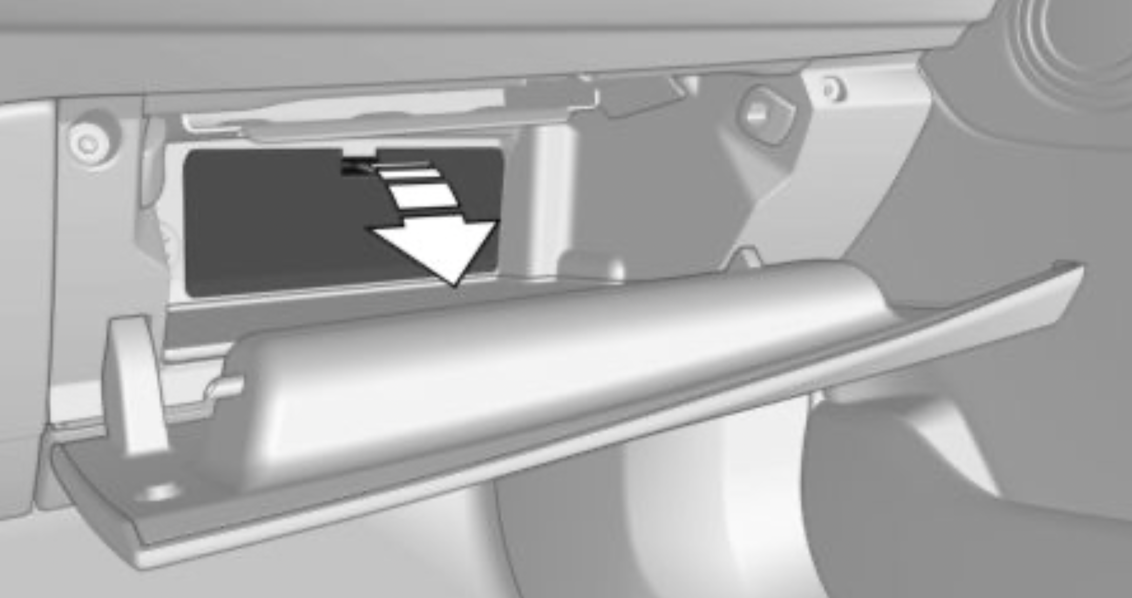
Replacing fuses
The vehicle manufacturer recommends that you have a dealer's service center or another qualified service center or repair shop replace the fuses.
This chapter describes all standard, country-specific and optional features offered with the series. It also describes features that are not necessarily available in your vehicle, e. g., due to the selected options or country versions. This also applies to safety-related functions and systems. When using these functions and systems, the applicable laws and regulations must be observed.

The button is located in the center console.
The red light in the button flashes when the hazard warning flashers are activated.

The warning triangle is located on the inside of the tailgate.
Move the warning triangle sideways and remove it.
General information
Some of the articles have a limited service life.
Check the expiration dates of the contents regularly and replace any expired items promptly.
Storage
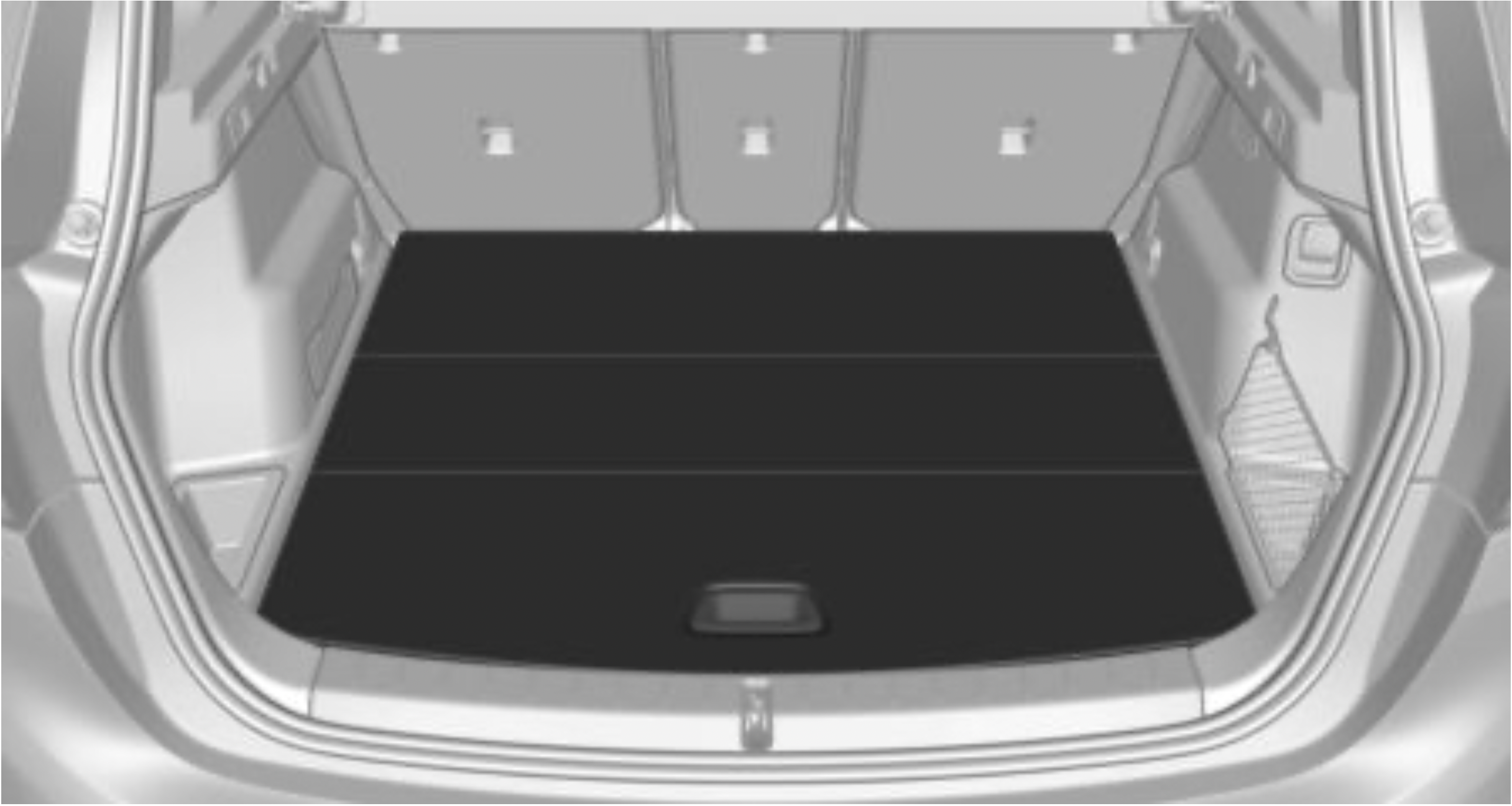
The first-aid kit is located beneath the cargo floor panel.
Intelligent emergency call
Concept
In case of an emergency, an Emergency Request can be triggered automatically by the system or manually.
Intelligent emergency call establishes a connection with the BMW Response Center.
General information
Only press the SOS button in an emergency.
For technical reasons, the Emergency Request cannot be guaranteed under unfavorable conditions.
Overview
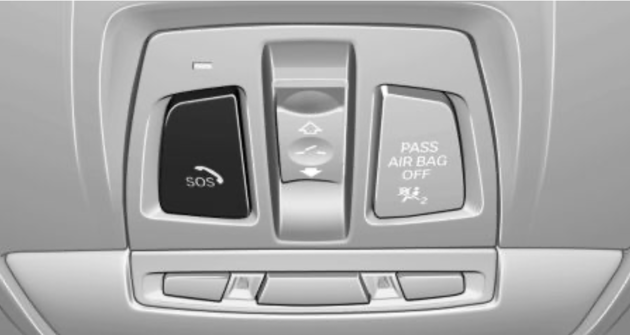
SOS button in the roofliner.
Functional requirements
Automatic triggering
Under certain conditions, for instance if the airbags trigger, an Emergency Request is automatically initiated immediately after an accident of corresponding severity. Automatic Collision Notification is not affected by pressing the SOS button.
Manual triggering
The BMW Response Center ends the Emergency Request.
General information
If the battery is discharged, the engine can be started using the battery of another vehicle and two jumper cables. Only use jumper cables with fully insulated clamp handles.
Safety information
DANGER: Contact with live components can lead to an electric shock. There is a risk of injuries or danger to life. Do not touch any components that are under voltage.
WARNING: If the jumper cables are connected in the incorrect order, sparking may occur. There is a risk of injury. Pay attention to the correct order during connection.
NOTE: In the case of body contact between the two vehicles, a short circuit can occur during jumpstarting. There is a risk of damage to property. Make sure that no body contact occurs.
Preparation
Starting aid terminals
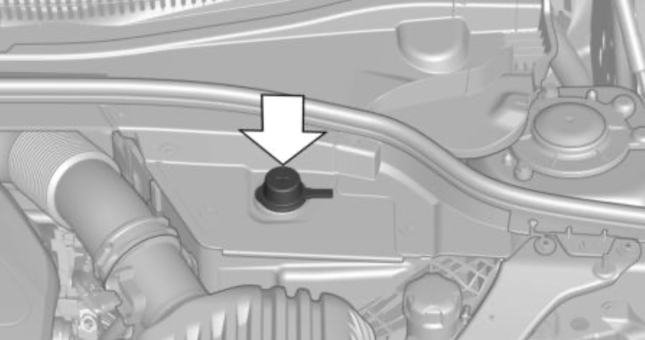
The starting aid terminal in the engine compartment acts as the battery's positive terminal.
Open the cover of the starting aid terminal.
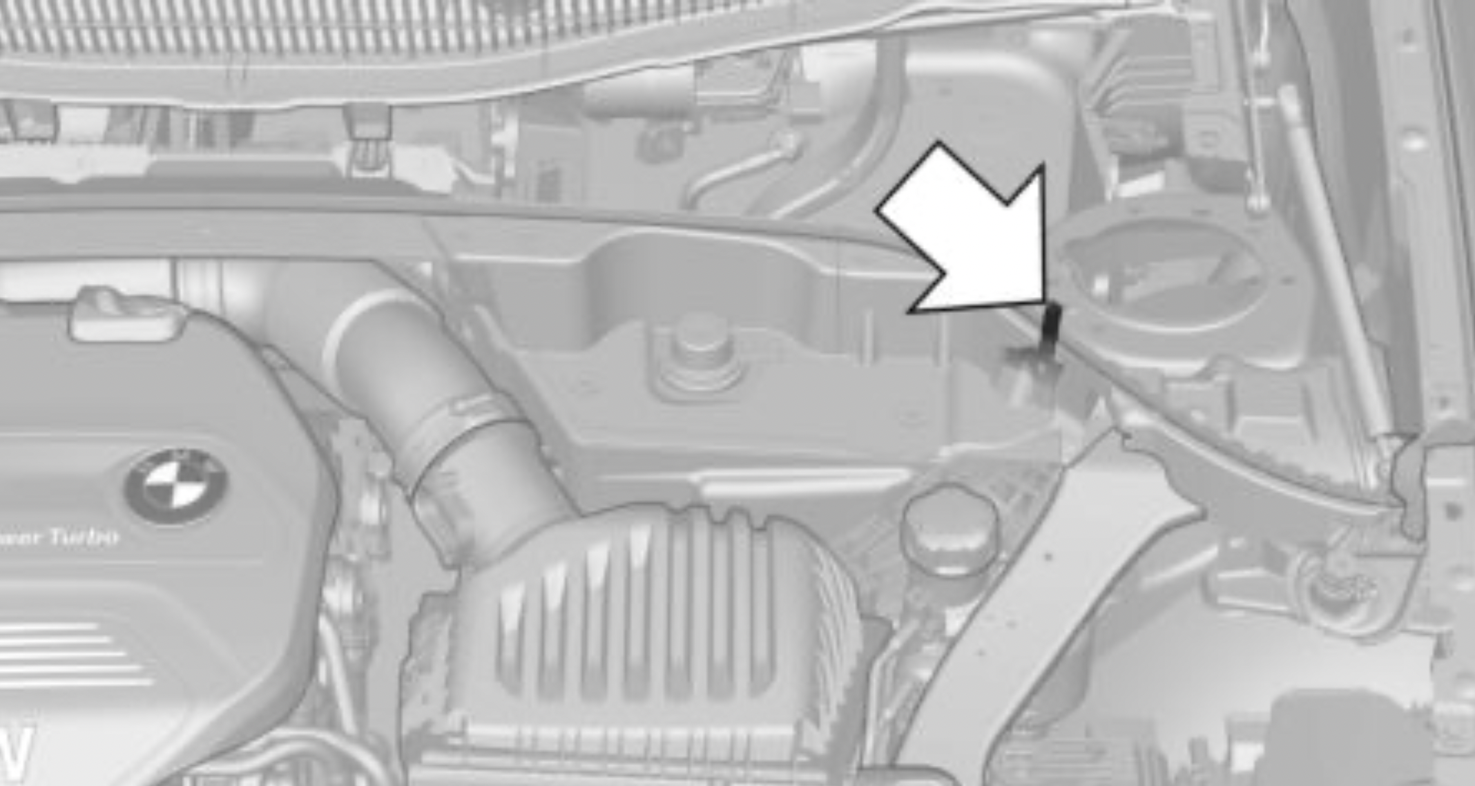
A special connection on the body acts as the battery negative terminal.
Connecting the cables
To prevent personal injury or damage to both vehicles, adhere strictly to the following procedure.
Starting the engine
Never use spray fluids to start the engine.
Check the battery and recharge, if needed.
Safety information
WARNING: Due to system limits, individual functions can malfunction during tow-starting/towing with the Intelligent Safety systems activated. There is a risk of an accident. Switch all Intelligent Safety systems off prior to tow-starting/towing.
Steptronic transmission without xDrive: transporting the vehicle
General information
The vehicle must not be towed if the front wheels are touching the ground.
Safety information
NOTE: The vehicle can be damaged when towing the vehicle with a lifted rear axle. There is a risk of damage to property. Have vehicle transported only with lifted front axle or on a loading platform.
Pushing the vehicle
To remove a broken-down vehicle from the danger area, it can be pushed for a short distance.
Roll or push, refer to page 124, the vehicle.
Tow truck
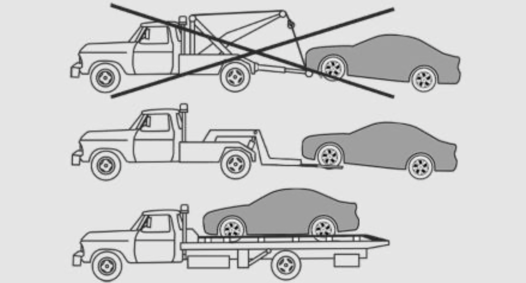
Your vehicle should be transported with a tow truck with a so-called lift bar or on a flat bed.
NOTE:
The vehicle can become damaged when lifting and securing it.
There is a risk of damage to property.
Steptronic transmission with xDrive: transporting the vehicle
General information
The vehicle is not permitted to be towed.
Pushing the vehicle
To remove a broken-down vehicle from the danger area, it can be pushed for a short distance.
Roll or push, refer to page 124, the vehicle.
Tow truck
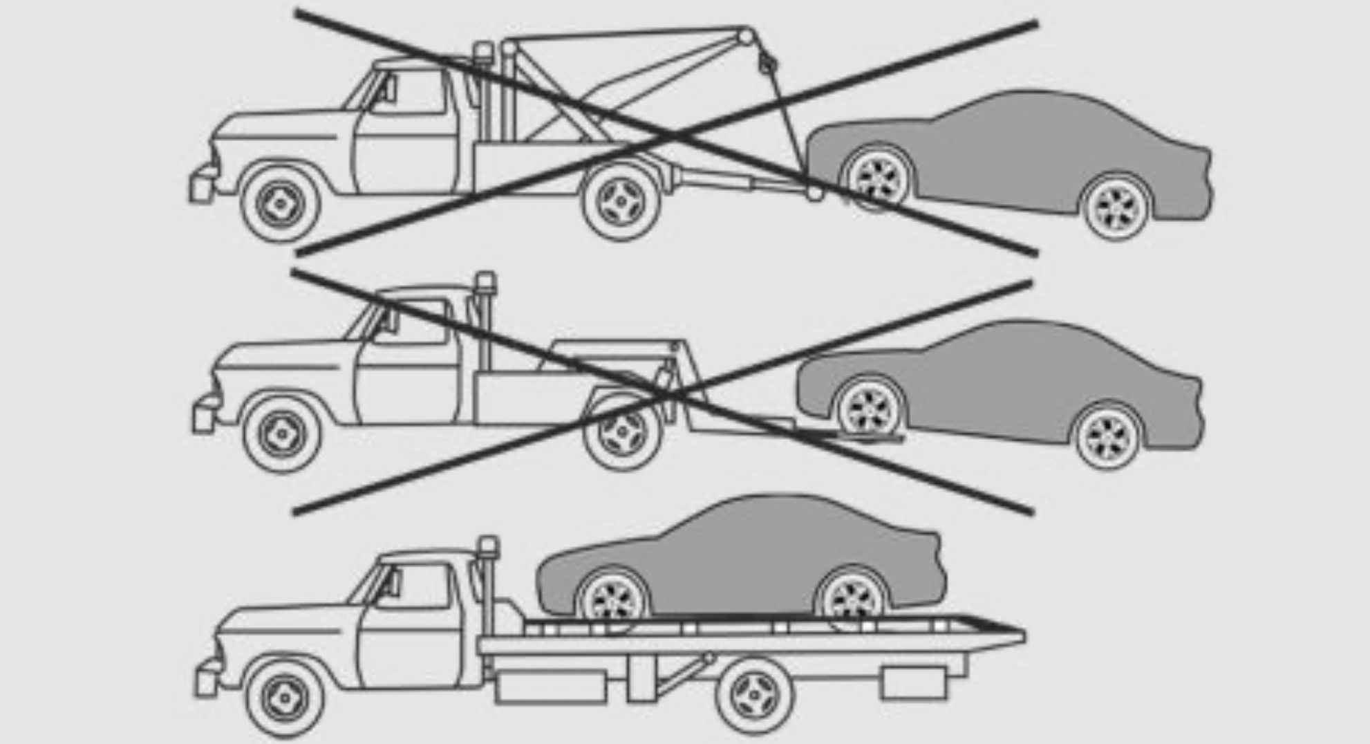
The vehicle should only be transported on a loading platform.
NOTE
The vehicle can become damaged when lifting and securing it.
There is a risk of damage to property.
Towing other vehicles
General information
Switch on the hazard warning system, depending on local regulations.
If the electrical system has failed, clearly identify the vehicle being towed by placing a sign or a warning triangle in the rear window.
Safety information
WARNING: If the approved gross vehicle weight of the towing vehicle is lighter than the vehicle to be towed, the tow fitting can tear off or it will not be possible to control the vehicle's response. There is a risk of an accident! Make sure that the gross vehicle weight of the towing vehicle is heavier than the vehicle to be towed.
NOTE: If the tow bar or tow rope is attached incorrectly, damage to other vehicle parts can occur. There is a risk of damage to property. Correctly attach the tow bar or tow rope to the tow fitting.
Tow bar
The tow fittings used should be on the same side on both vehicles.
Should it prove impossible to avoid mounting the tow bar at an offset angle, please follow the following:
Tow rope
When starting to tow the vehicle, make sure that the tow rope is taut.
Use nylon ropes or straps, which will enable the vehicle to be towed without jerking.
Tow fitting
General information
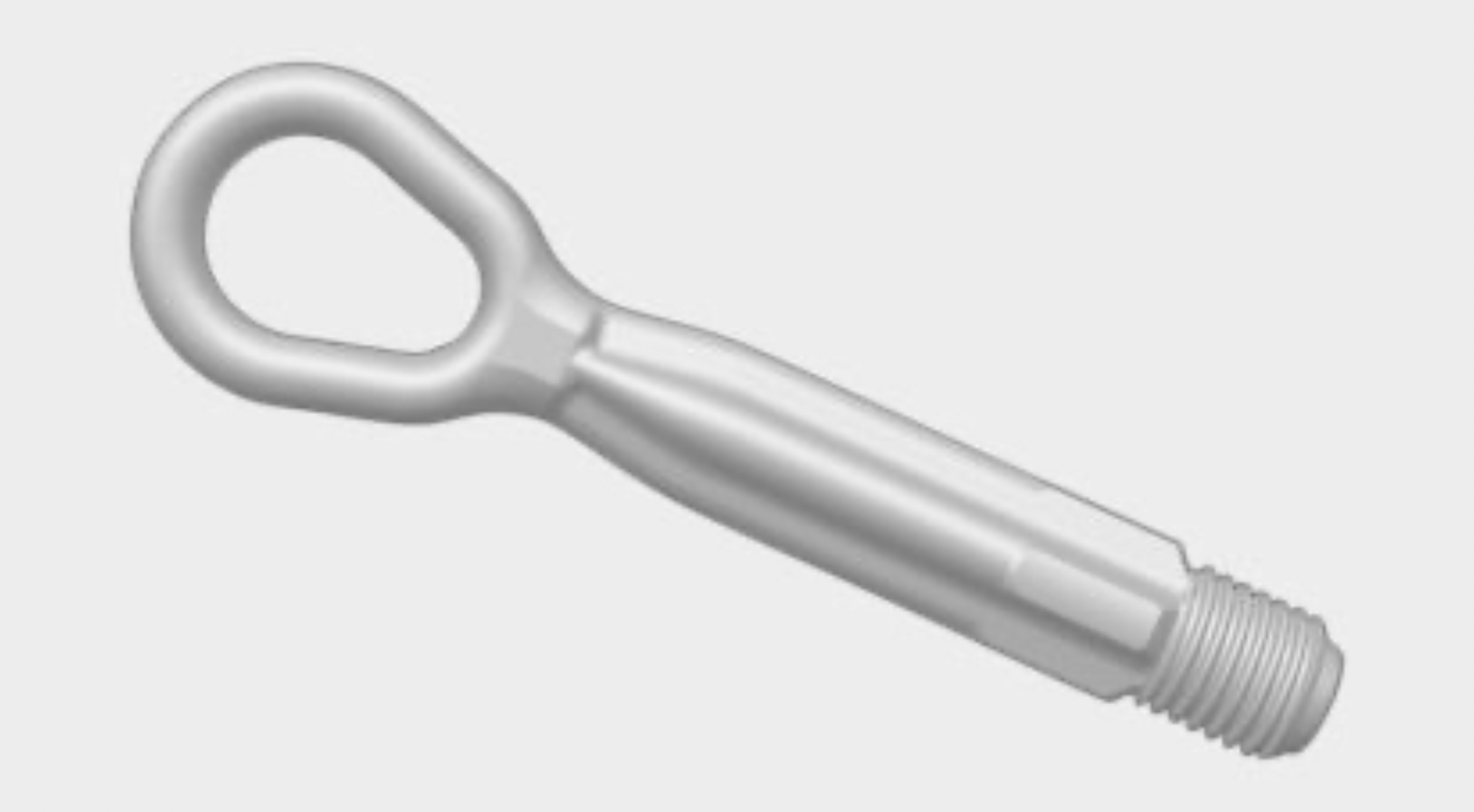
The screw-in tow fitting should always be carried in the vehicle.
The tow fitting can be screwed in at the front or rear of the vehicle.
The tow fitting and the onboard vehicle tool kit, refer to page 273, are together in the cargo area.
Use of the tow fitting:
Safety information
NOTE: If the tow fitting is not used as intended, there may be damage to the vehicle or to the tow fitting. There is a risk of damage to property. Follow the notes on using the tow fitting.
Screw thread for tow fitting
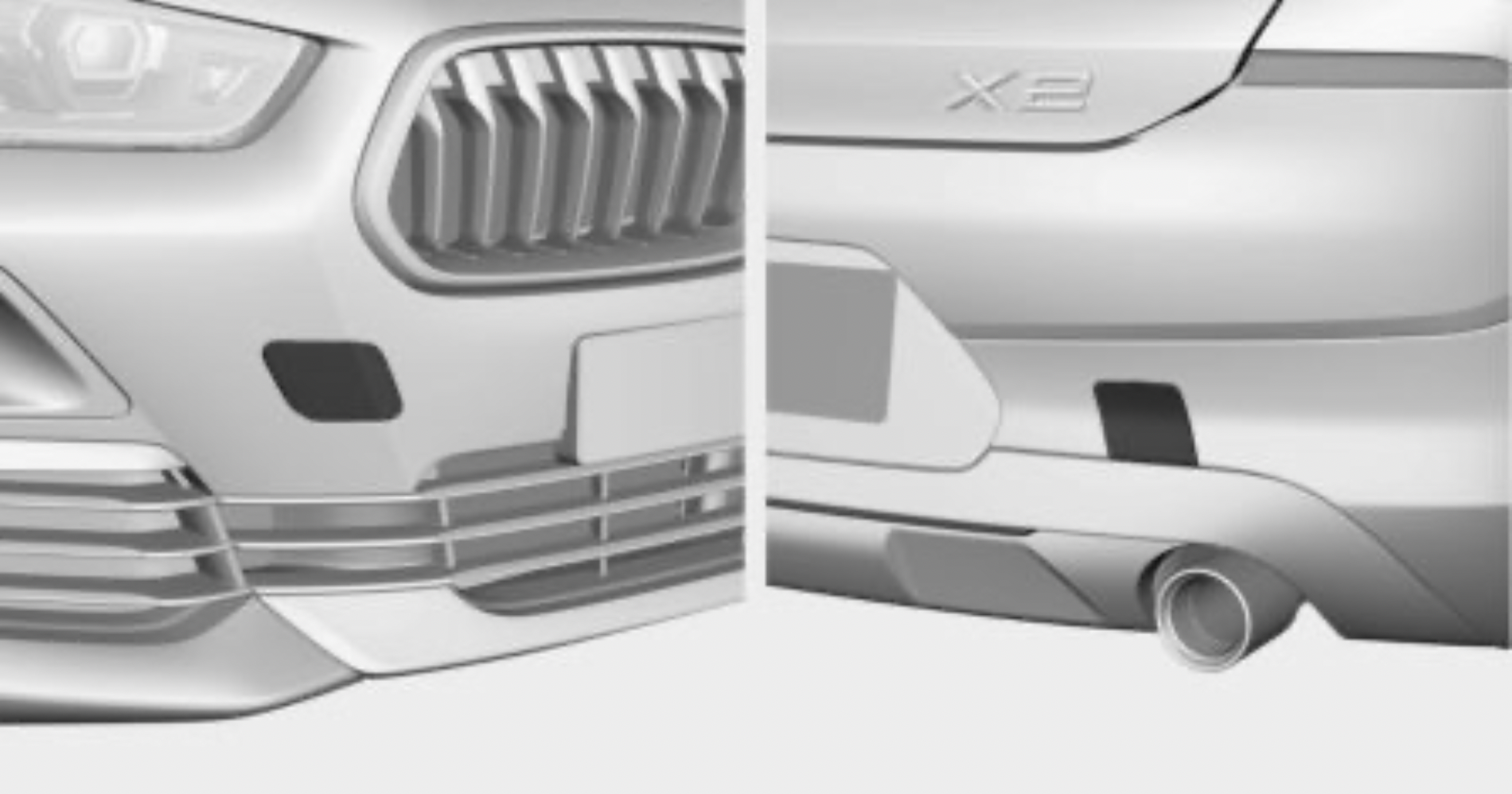
Press on the mark on the edge of the cover to push it out.
Tow-starting
Steptronic transmission
Do not tow-start the vehicle.
Tow-starting the engine is not possible due to the Steptronic transmission.
Have the reasons for the starting difficulties corrected by a dealer’s service center or another qualified service center or repair shop.
This chapter describes all standard, country-specific and optional features offered with the series. It also describes features that are not necessarily available in your vehicle, e. g., due to the selected options or country versions. This also applies to safety-related functions and systems. When using these functions and systems, the applicable laws and regulations must be observed.
General information
Regularly remove foreign objects such as leaves in the area below the windshield when the hood is raised.
Wash your vehicle frequently, particularly in winter. Intense soiling and road salt can damage the vehicle.
Steam blaster and high-pressure washer
Safety information
NOTE: When cleaning with high-pressure washers, components can be damaged due to the pressure or temperatures being too high. There is a risk of damage to property. Maintain sufficient distance and do not spray too long continuously. Follow the operating instructions for the high-pressure washer.
Distances and temperature
Automatic vehicle washes
Safety information
NOTE: Improper use of automatic vehicle washes can cause damage to the vehicle. There is a risk of damage to property. Follow the following instructions:
Driving into a vehicle wash with a Steptronic transmission
General information
In a vehicle wash, the vehicle must be able to roll freely.
Roll or push the vehicle, refer to page 124.
Some vehicle washes do not permit persons in the vehicle. The vehicle cannot be locked from the outside when in selector lever position N. A signal sounds when an attempt is made to lock the vehicle.
Driving out of a vehicle wash
Make sure that the remote control is in the vehicle.
Start the engine. Starting the engine, refer to page 108.
Headlights
Do not rub wet headlights dry and do not use abrasive or acidic cleaning agents.
Soak areas that have been dirtied, for instance from insects, with shampoo and wash off with water.
Thaw ice with de-icing spray; do not use an ice scraper.
After washing the vehicle
After washing the vehicle, apply the brakes briefly to dry them; otherwise, braking action can be reduced. The heat generated during braking dries brake discs and brake pads and protects them against corrosion.
Completely remove all residues on the windows, to minimize loss of visibility due to smearing and to reduce wiper noises and wiper blade wear.
Vehicle care products
General information
BMW recommends using vehicle care and cleaning products from BMW. Suitable care products are available from a dealer’s service center or another qualified service center or repair shop.
Safety information
WARNING: Cleansers can contain substances that are dangerous and harmful to your health. There is a risk of injury. When cleaning the interior, open the doors or windows. Only use products intended for cleaning vehicles. Follow the instructions on the container.
Vehicle paint
General information
Regular care contributes to driving safety and value retention. Environmental influences in areas with elevated air pollution or natural contaminants, such as tree resin or pollen can affect the vehicle's paintwork. Tailor the frequency and extent of your vehicle care to these influences.
Aggressive substances such as spilled fuel, oil, grease or bird droppings, must be removed immediately to prevent the finish from being altered or discolored.
Matte finish
Only use cleaning and care products suitable for vehicles with matte finish.
Leather care
Remove dust from the leather regularly, using a cloth or vacuum cleaner.
Otherwise, particles of dust and road grime chafe in pores and folds, and lead to increased wear and premature degradation of the leather surface.
To guard against discoloration, such as from clothing, clean leather and provide leather care roughly every two months.
Clean light-colored leather more frequently because soiling on such surfaces is substantially more visible.
Use leather care products; otherwise, dirt and grease will gradually break down the protective layer of the leather surface.
Upholstery material care
General information
Vacuum the upholstery regularly with a vacuum cleaner.
If upholstery is very dirty, for instance with beverage stains, use a soft sponge or microfiber cloth with a suitable interior cleaner.
Clean the upholstery down to the seams using large sweeping motions. Avoid rubbing the material vigorously.
Safety information
NOTE: Open Velcro® fasteners on articles of clothing can damage the seat covers. There is a risk of damage to property. Ensure that any Velcro® fasteners are closed.
Caring for special components
Light-alloy wheels
When cleaning the vehicle, use only neutral wheel cleaners having a pH value from 5 to 9. Do not use abrasive cleaning agents or steam jets above 140 ℉/60 ℃. Follow the manufacturer's instructions.
Aggressive, acidic or alkaline cleaning agents can destroy the protective layer of adjacent components, such as the brake disc.
After cleaning, apply the brakes briefly to dry them. The heat generated during braking dries brake discs and brake pads and protects them against corrosion.
Chrome surfaces
Carefully clean components such as the radiator grille or door handles with an ample supply of water, possibly with shampoo added, particularly when they have been exposed to road salt.
Rubber components
Environmental influences can cause surface soiling of rubber parts and a loss of gloss. Use only water and suitable cleaning agents for cleaning.
Treat especially worn rubber parts with rubber care agents at regular intervals. When cleaning rubber seals, do not use any silicon-containing vehicle care products in order to avoid damage or noises.
Fine wood parts
Clean fine wood facing and fine wood components only with a moist rag. Then dry with a soft cloth.
Plastic components
NOTE: Cleansers that contain alcohol or solvents, such as lacquer thinners, heavy-duty grease removers, fuel, or such, can damage plastic parts. There is a risk of damage to property. Clean with a microfiber cloth. Dampen cloth lightly with water.
Plastic components are e.g.:
Clean with a microfiber cloth.
Dampen cloth lightly with water.
Do not soak the roofliner.
Safety belts
WARNING: Chemical cleansers can destroy the safety belt webbing. Missing protective effect of the safety belts. There is a risk of injuries or danger to life. Use only a mild soapy solution for cleaning the safety belts.
Dirty belt straps impede the reeling action and thus have a negative impact on safety.
Use only a mild soapy solution, with the safety belts clipped into their buckles.
Safety belts should only be allowed to retract if they are dry.
Carpets and floor mats
WARNING: Objects in the driver's floor area can limit the pedal distance or block a depressed pedal. There is a risk of an accident. Stow objects in the vehicle such that they are secured and cannot enter into the driver's floor area. Use floor mats that are suitable for the vehicle and can be safely attached to the floor. Do not use loose floor mats and do not layer several floor mats. Make sure that there is sufficient clearance for the pedals. Ensure that the floor mats are securely fastened again after they were removed, for instance for cleaning.
Floor mats can be removed from the car's interior for cleaning.
If the floor carpets are very dirty, clean with a microfiber cloth and water or a textile cleaner. To prevent matting of the carpet, rub back and forth in the direction of travel only.
Sensor/camera lenses
To clean sensors and camera lenses, use a cloth moistened with a small amount of glass detergent.
Displays/Screens/protective glass of the Head-up Display
NOTE: Chemical cleansers, moisture or fluids of any kind can damage the surface of displays and screens. There is a risk of damage to property. Clean with a clean, antistatic microfiber cloth.
NOTE: The surface of displays can be damaged with improper cleaning. There is a risk of damage to property. Avoid pressure that is too high and do not use any scratching materials.
Clean with a clean, antistatic microfiber cloth.
Clean the protective glass of the Head-up Display using a microfiber cloth and commercially available dish-washing soap.
Long-term vehicle storage
When the vehicle is shut down for longer than three months, special measures must be taken. Further information is available from a dealer’s service center or another qualified service center or repair shop.