
Loading ...
Loading ...
Loading ...
INSTALLATION
After unpacking the product, check for any damage during transport. In case of problems, contact the dealer or the After-Sales Service. For built-in dimensions and
installation instruction, see the pictures in page 2.
Preparing the cabinet for tting
WARNING
- Install a separator panel under the hob.
- The lower part of the product must not be accessible
after installation.
- Do not t the separator panel if an undertop oven is
installed.
• The distance between the underside of the appliance and the separator panel must respect the dimensions given in the gure.
• In order to ensure the correct operation of the product, do not obstruct the minimum required clearance between the hob and the top of the unit (min. 5 mm).
• If an undertop oven is installed, make sure the oven is equipped with a cooling system.
• Do not install the hob above a dishwasher or washing-machine, so that the electronic circuits do not come into contact with steam or moisture which could damage them.
• In the case of ush-mounted installation, call the After-Sales Service to request assembly of screws kit 4801 211 00112.
• To remove the hob, use a screwdriver (not provided) to prise off the perimeter clips on the underside of the appliance.
ELECTRICAL CONNECTION
WARNING
- Disconnect the appliance from the power supply.
- Installation must be carried out by qualied personnel who know the current safety and installation regulations.
- The manufacturer declines all liability for injury to persons or animals and for damage to property resulting from
failure to observe the regulations provided in this chapter.
- The power cable must be long enough to allow the hob to be removed from the worktop.
- Make sure the voltage specied on the dataplate located on the bottom of the appliance is the same as that of the home.
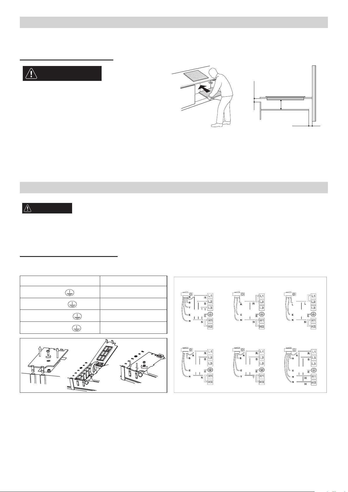
Connection to the terminal block
For the electrical connection, use an H05RR-F or H05V2V2-F cable as specied in the table below.
Wires Number x size
220-240V ~ +
380-415V 2N~ +
220-240V 3~ +
380-415V 3N~ +
3 x 4 mm
4 x 1,5 mm
5 x 1,5 mm
4 x 1,5 mm
CBA
230 V
230 V
230 V
230 V
230 V
230 V
230 V
230 V
230 V
230 V
230 V
220-240 V ~ (AU and UK)
220-240 V 3~
(Belgium only)
380-415 V 2N~
220-240 V ~380-415 V 3N~
380-415 V 2N~
(Holland only)
Important:
- Based on the wiring diagram (see gure) either keep or remove the metal jumpers between the screws on the terminal block L1-L2 and N1-N2.
- If the cable is provided, see the connection instructions attached to the cable.
- Make sure all six screws on the terminal block are tightened after connecting the cables.
Example of jumper present (left) or removed (right). See the wiring diagram for details (the jumpers can be between L1-L2 and between N1-N2).
Min. 5 mm
Min. 20 mm
Min. 5 mm
Loading ...
Loading ...
Loading ...