Loading ...
Loading ...
Loading ...
9
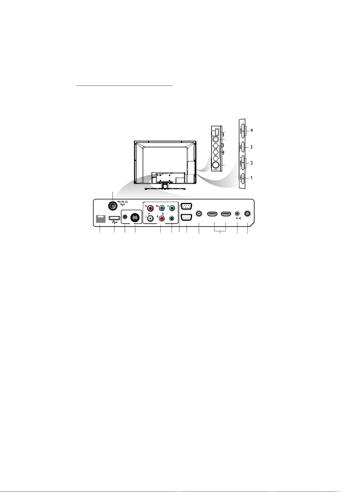
5. Overview of TV
connectors and controls
CHANNEL
6
DATA 1
CVI
PC
AUDIO IN
HDMI 1
AV 1
HDMI 2 SERVICE
RS
232
SPDIF
S-VIDEO
VGA
8
AUDIO IN
AV
5
1514789 10 1213
1716
USB
18
21
20
19
11
B Warning:
Risk of electric shock. The rear jack •
panel must be removed by qualified
personnel only.
Do not connect any telephone cables •
or equipment to Data 1.
. 1. POWER
To switch the TV on and off. To
disconnect from the mains, remove the
mains cord from the mains socket at the
back of the TV or remove the mains plug
from the wall socket.
- CHANNEL + 2.
To select a channel.
MENU3.
To display or close menus.
- VOLUME + 4.
To increase or decrease volume.
TV Aerial5.
To connect to the aerial plug.
DATA 16.
For Pay Per View Terminal connection.
USB7.
To play media, clone and upgrade
software.
AV 18.
A replacement for the standard audio
and video cables - red, white and
yellow. To connect to video camera or
camcorder.
S-Video9.
To play video from an external device.
The audio is provided by the AV 1 jack.
Note: D Switching between AV 1 and
S-Video does not occur automatically. Set
the input to S-Video (see Select an input
source on page 17 ).
Component Video Inputs/Audio 10.
Inputs
To connect to a DVD player or decoder
which have the same connectors.
Loading ...
Loading ...
Loading ...