2020 ARMADA
OWNER’S MANUAL
and MAINTENANCE INFORMATION
For your safety, read carefully and keep in this vehicle.
WARNING
Operating, servicing and main-
taining a passenger vehicle or
off-highway motor vehicle can
expose you to chemicals in-
cluding engine exhaust, carbon
monoxide, phthalates, and
lead, which are known to the
State of California to cause
cancer and birth defects or
other reproductive harm. To
minimize exposure, avoid
breathing exhaust, do not idle
the engine except as neces-
sary, service your vehicle in a
well-ventilated area and wear
gloves or wash your hands
frequently when servicing your
vehicle. For more information
go to www.P65Warnings.ca.
gov/passenger-vehicle.
This manual was prepared to help you
understand the operation and mainte-
nance of your vehicle so that you may
enjoy many miles of driving pleasure.
Please read through this manual before
operating your vehicle.
A separate Warranty Information Book-
let explains details about the warranties
covering your vehicle. Additionally, a
separate Customer Care/Lemon Law
Booklet (U.S. only) will explain how to
resolve any concerns you may have
with your vehicle, as well as clarify your
rights under your state’s lemon law.
In addition to factory installed options,
your vehicle may also be equipped with
additional accessories installed by NISSAN
or by your NISSAN dealer prior to delivery.
It is important that you familiarize your-
self with all disclosures, warnings, cau-
tions and instructions concerning proper
use of such accessories prior to operating
the vehicle and/or accessory. It is recom-
mended that you see a NISSAN dealer for
details concerning the particular acces-
sories with which your vehicle is
equipped.
Your NISSAN dealer knows your vehicle
best. When you require any service or
have any questions, we will be glad to
assist you with the extensive resources
available to us.
READ FIRST — THEN DRIVE SAFELY
Before driving your vehicle, read your
Owner’s Manual carefully. This will ensure
familiarity with controls and maintenance
requirements, assisting you in the safe
operation of your vehicle.
WARNING
IMPORTANT SAFETY INFORMATION
REMINDERS!
Follow these important driving rules
to help ensure a safe and comforta-
ble trip for you and your passengers!
. NEVER drive under the influence
of alcohol or drugs.
. ALWAYS observe posted speed
limits and never drive too fast
for conditions.
. ALWAYS give your full attention to
driving and avoid using vehicle
features or taking other actions
that could distract you.
. ALWAYS use your seat belts and
appropriate child restraint sys-
tems. Pre-teen children should
be seated in the rear seat.
. ALWAYS provide information
about the proper use of vehicle
CALIFORNIA PROPOSITION
65 WARNING
Foreword
safety features to all occupants
of the vehicle.
. ALWAYS review this Owner’s Man-
ual for important safety informa-
tion.
ON-PAVEMENT AND OFF-ROAD
DRIVING
This vehicle will handle and maneuver
differently from an ordinary passenger
car because it has a higher center of
gravity for off-road use. As with other
vehicles with features of this type,
failure to operate this vehicle correctly
may result in loss of control or an
accident. Be sure to read “On-pave-
ment and off-road driving precau-
tions”, “Avoiding collision and rollover”
and “Driving safety precautions” in the
“5. Starting and driving” section of this
manual.
MODIFICATION OF YOUR VEHI-
CLE
This vehicle should not be modified.
Modification could affect its perfor-
mance, safety or durability, and may
even violate governmental regula-
tions. In addition, damage or perfor-
mance problems resulting from
modification will not be covered under
the NISSAN warranties.
WARNING
Installing an aftermarket On-Board
Diagnostic (OBD) plug-in device that
uses the port during normal driving,
for example remote insurance com-
pany monitoring, remote vehicle di-
agnostics, telematics or engine
reprogramming, may cause interfer-
ence or damage to vehicle systems.
We do not recommend or endorse
the use of any aftermarket OBD
plug-in devices, unless specifically
approved by NISSAN. The vehicle
warranty may not cover damage
caused by any aftermarket plug-in
device.
WHEN READING THE MANUAL
This manual includes information for all
features and equipment available on
this model. Features and equipment in
your vehicle may vary depending on
model, trim level, options selected, or-
der, date of production, region or avail-
ability. Therefore, you may find
information about features or equip-
ment that are not included or installed
on your vehicle.
All information, specifications and illustra-
tions in this manual are those in effect at
the time of printing. NISSAN reserves the
right to change specifications, perfor-
mance, design or component suppliers
without notice and without obligation.
From time to time, NISSAN may update
or revise this manual to provide owners
with the most accurate information cur-
rently available. Please carefully read and
retain with this manual all revision up-
dates sent to you by NISSAN to ensure
you have access to accurate and up-to-
date information regarding your vehicle.
Current versions of vehicle Owner’s Man-
uals and any updates can also be found in
the Owner section of the NISSAN website
at https://owners.nissanusa.com/now-
ners/navigation/manualsGuide. If you
have questions concerning any informa-
tion in your Owner’s Manual, contact
NISSAN Consumer Affairs. See the NISSAN
CUSTOMER CARE PROGRAM page in this
Owner’s Manual for contact information.
IMPORTANT INFORMATION ABOUT
THIS MANUAL
You will see various symbols in this
manual. They are used in the following
ways:
WARNING
This is used to indicate the presence
of a hazard that could cause death or
serious personal injury. To avoid or
reduce the risk, the procedures must
be followed precisely.
CAUTION
This is used to indicate the presence
of a hazard that could cause minor
or moderate personal injury or da-
mage to your vehicle. To avoid or
reduce the risk, the procedures must
be followed carefully.
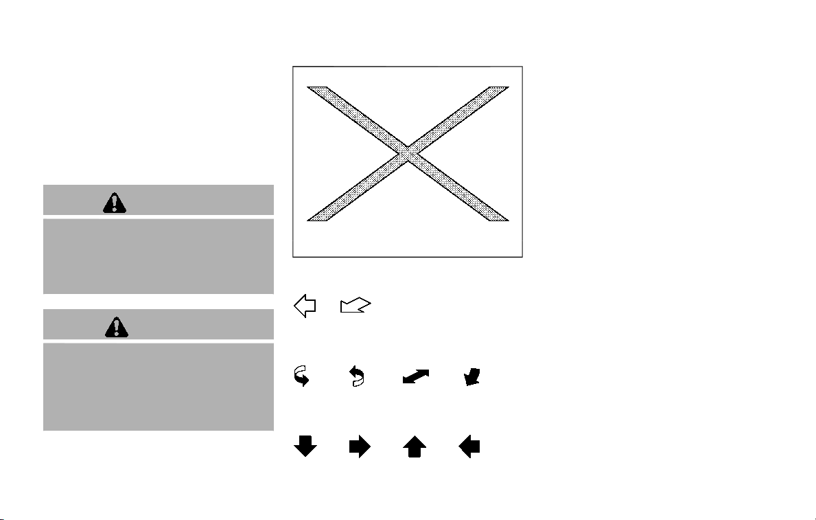
SIC0697
If you see the symbol above, it means “Do
not do this” or “Do not let this happen”.
If you see a symbol similar to those above
in an illustration, it means the arrow
points to the front of the vehicle.
Arrows in an illustration that are similar to
those above indicate movement or ac-
tion.
Arrows in an illustration that are similar to
those above call attention to an item in
the illustration.
CALIFORNIA PERCHLORATE ADVI-
SORY
Some vehicle parts, such as lithium
batteries, may contain perchlorate ma-
terial. The following advisory is pro-
vided: “Perchlorate Material - special
handling may apply, See www.dtsc.ca.
gov/hazardouswaste/perchlorate.”
© 2019 NISSAN MOTOR CO., LTD.
All rights reserved. No part of this Owner’s
Manual may be reproduced or stored in a
retrieval system, or transmitted in any
form, or by any means, electronic, me-
chanical, photocopying, recording or
otherwise, without the prior written per-
mission of Nissan Motor Co., Ltd.

NISSAN CUSTOMER CARE PROGRAM
NISSAN CARES ...
Both NISSAN and your NISSAN dealer are dedicated to serving all your automotive needs. Your satisfaction with your vehicle and your
NISSAN dealer are our primary concerns. Your NISSAN dealer is always available to assist you with all your automobile sales and
service needs.
However, if there is something that your
NISSAN dealer cannot assist you with or
you would like to provide NISSAN directly
with comments or questions, please con-
tact the NISSAN Consumer Affairs Depart-
ment using our toll-free number:
For U.S. customers
1-800-NISSAN-1
(1-800-647-7261)
For Canadian customers
1-800-387-0122
The Consumer Affairs Department will
ask for the following information:
. Your name, address, and telephone
number
. Vehicle identification number (at-
tached to the top of the instrument
panel on the driver’s side)
. Date of purchase
. Current odometer reading
. Your NISSAN dealer’s name
. Your comments or questions
OR
You can write to NISSAN with the infor-
mation at:
For U.S. customers
Nissan North America, Inc.
Consumer Affairs Department
P.O. Box 685003
Franklin, TN 37068-5003
or via e-mail at:
nnaconsumeraffairs@nissan-usa.
com
For Canadian customers
Nissan Canada Inc.
5290 Orbitor Drive
Mississauga, Ontario L4W 4Z5
or via e-mail at:
information.centre@nissancana-
da.com
If you prefer, visit us at:
www.nissanusa.com (for U.S. customers)
or
www.nissan.ca (for Canadian customers)
We appreciate your interest in NISSAN
and thank you for buying a quality NISSAN
vehicle.


Illustrated table of contents
0
Safety — seats, seat belts and supplemental restraint
system
1
Instruments and controls
Pre-driving checks and adjustments
Monitor, heater, air conditioner, audio, phone and voice
recognition systems
Starting and driving
In case of emergency
Appearance and care
Do-it-yourself
Maintenance and schedules
Technical and consumer information
2
3
4
5
6
7
8
9
10
Table of
Contents
Index
11


0 Illustrated table of contents
Seats, seat belts and Supplemental Restraint
System (SRS) ..................................................................................... 0-2
Exterior front .................................................................................... 0-3
Exterior rear ...................................................................................... 0-4
Passenger compartment ....................................................... 0-5
Cockpit .................................................................................................. 0-6
Instrument panel ......................................................................... 0-7
Meters and gauges .................................................................... 0-8
Engine compartment ............................................................... 0-9
VK56VD engine ..................................................................... 0-9
Warning and indicator lights ........................................... 0-10
0-2 Illustrated table of contents
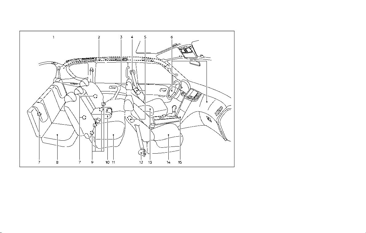
JVC1212X
1. Seat belt for 3rd row center seat (P.1-26)
2. Roof-mounted curtain side-impact and
rollover supplemental air bags (P.1-54)
3. Head Restraints (P.1-14)
— Front-seat Active Head Restraints
(P.1-19)
4. Seat belts (P.1-20)
5. Front seat-mounted side-impact supple-
mental air bags (P.1-54)
6. Supplemental front-impact air bags
(P.1-54)
7. Child restraint anchor points (for top
tether strap child restraint) (P.1-46, P.1-50)
8. 3rd row seats (P.1-7)
— Child restraints (P.1-32)
9. LATCH (Lower Anchors and Tethers for
CHildren) system (P.1-35)
10. Armrest (2nd row seat) (P.1-11)
11. 2nd row seats (P.1-5)
— Child restraints (P.1-32)
12. Seat belt pretensioner (P.1-69)
13. Front armrest (P.1-11)
14. Front seats (P.1-4)
— Occupant classification sensors
(weight sensors) (P.1-60)
15. Front passenger air bag status light
(P.1-62)
SEATS, SEAT BELTS AND SUPPLEMENTAL
RESTRAINT SYSTEM (SRS)
JVC0953X
1. Hood (P.3-21)
2. Windshield wiper and washer
— Switch operation (P.2-33)
— Window washer fluid (P.8-10)
— Windshield wiper deicer (if so equipped)
(P.2-36)
3. Moonroof (if so equipped) (P.2-65)
4. Power windows (P.2-63)
5. Roof rack (P.2-60)
6. Sensors
— Camera aiding sonar function (models
with Intelligent Around View Monitor)
(P.4-25)
— Sonar system (if so equipped) (P.5-127)
7. Towing hook (P.6-19)
8. Front view camera (if so equipped) (P.4-10)
9. Fog light (if so equipped) (P.2-41)
10. Headlights and turn signal lights (P.2-37)
11. Tires
— Wheel and tires (P.8-30, P.10-8)
— Flat tire (P.6-3)
— Tire Pressure Monitoring System
(TPMS) (P.2-15, P.5-5)
12. Outside mirrors (P.3-38)
— Side view camera (P.4-10)
— Welcome light (if so equipped) (P.2-67)
13. Side turn signal lights (P.8-24)
14. Doors
— Keys (P.3-2)
— Door locks (P.3-4)
— Intelligent Key system (P.3-7)
— Remote keyless entry system (P.3-15)
— Remote engine start (if so equipped)
(P.3-19)
15. Child safety rear door locks (P.3-6)
Illustrated table of contents 0-3
EXTERIOR FRONT
0-4 Illustrated table of contents
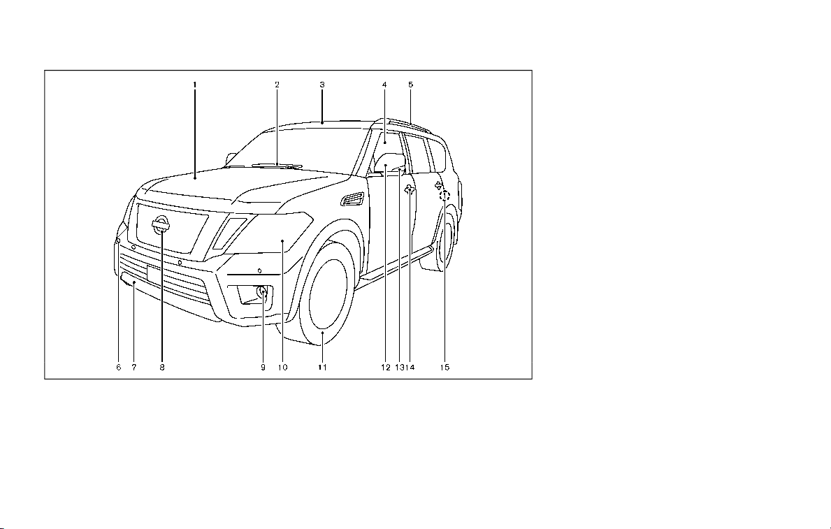
JVC1091X
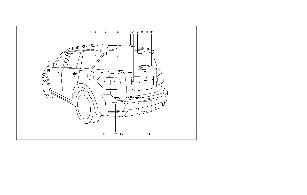
1. Fuel-filler door (P.3-26)
— Fuel information (P.10-3)
2. Antenna (P.4-43)
3. Rear combination light (P.8-24)
4. Rear window defroster (P.2-36)
5. Satellite antenna (P.4-44)
6. Rear view camera (P.4-3, P.4-10)
7. Intelligent Rear View Mirror camera (if so
equipped) (P.3-32)
8. High-mounted stop light (P.8-24)
9. Liftgate (P.3-22)
— Intelligent Key system (P.3-7)
10. Rear window wiper and washer
— Switch operation (P.2-36)
— Window washer fluid (P.8-10)
11. Spare tire (under the vehicle) (P.6-3)
12. Sensors
— Camera aiding sonar function (models
with Intelligent Around View Monitor)
(P.4-25)
— Intelligent Back-up Intervention (I-BI) (if
so equipped) (P.5-53)
— Sonar system (if so equipped) (P.5-127)
13. Towing hook (P.6-19)
14. Trailer hitch (P.10-22)
EXTERIOR REAR

JVC1211X
1. Cargo light (P.2-70)
2. Cup holders (3rd row seat) (P.2-54)
3. Rear ventilators (P.4-34)
4. Coat hooks (P.2-59)
5. Rear personal lights (P.2-68)
6. Tray (P.2-58)
7. Door armrest
— Power window controls (P.2-63)
— Power door lock switch (P.3-5)
— Outside mirror remote control switch
(driver’s side) (P.3-38)
8. Automatic drive positioner switch (if so
equipped) (P.3-40)
9. Sun visors (P.3-30)
10. Map lights (P.2-68)
11. Moonroof switch (if so equipped) (P.2-65)
12. SOS call switch (if so equipped) (See
NissanConnect® Owner’s Manual)
13. Sunglasses holder (P.2-55)
14. Inside mirror (P.3-31)
— Intelligent Rear View Mirror (if so
equipped) (P.3-32)
— HomeLink® universal transceiver (if so
equipped) (P.2-70, P.2-74)
15. Cargo area
— Power outlet (P.2-50)
— Cargo floor box (P.2-60)
— Luggage hooks (P.2-59)
— Jacking tools (P.6-5)
16. Rear console box (if so equipped) (P.2-57)
— Cup holders (2nd row seat) (P.2-53)
— Pocket (P.2-57)
17. Cup holders (2nd row seat) (if so
equipped) (P.2-53)
18. Mobile Entertainment System (MES) (if so
equipped) (See NissanConnect® Owner’s
Manual)
19. Console box (P.2-56)
— Power outlet (P.2-50)
— USB charging connector (P.2-52)
— Rear Media Interface (See NissanCon-
nect® Owner’s Manual)
— Rear automatic air conditioning sys-
tem (if so equipped) (P.4-39)
20. Front cup holders (P.2-53)/Tray (P.2-58)
Illustrated table of contents 0-5
PASSENGER COMPARTMENT

0-6 Illustrated table of contents
WAA0101X
1. Power liftgate switch (if so equipped)
(P.3-22)
2. Heated steering wheel switch (if so
equipped) (P.2-42)
3. Instrument brightness control switch
(P.2-40)
4. TRIP/RESET switch for twin trip odometer
(P.2-6)
5. Headlight, fog light and turn signal switch
— Headlight (P.2-37)
— Turn signal (P.2-41)
— Fog light (if so equipped) (P.2-41)
6. Steering-wheel-mounted controls (left
side)
— Audio control steering switch (See
NissanConnect® Owner’s Manual)
— Hands-Free Phone System switch (See
NissanConnect® Owner’s Manual)
7. Trip computer switch (P.2-28)
8. Wiper and washer switch (P.2-33)
9. Steering-wheel-mounted controls (right
side)
— Intelligent Cruise Control (ICC) system
(P.5-63)
10. Dynamic driver assistance switch (if so
equipped)
— Intelligent Lane Intervention (I-LI) sys-
tem (if so equipped) (P.5-23)
— Intelligent Distance Control (I-DC) sys-
tem (if so equipped) (P.5-85)
— Intelligent Blind Spot Intervention (I-
BSI) system (if so equipped) (P.5-40)
11. Shift lever (P.5-17)
12. Four-Wheel Drive (4WD) shift switch (if so
equipped) (P.5-116)/SNOW mode switch
(P.2-46)/TOW MODE switch (P.2-47)/Vehi-
cle Dynamic Control (VDC) OFF switch
(P.5-133)
13. Power liftgate main switch (if so
equipped) (P.3-22)
14. Warning systems switch (if so equipped)
(P.2-46)
— Lane Departure Warning (LDW) (if so
equipped) (P.5-23)
— Blind Spot Warning (BSW) (if so
equipped) (P.5-32)
15. Rear door alert switch (P.2-48)
16. Electric tilting/telescopic steering wheel
switch (P.3-29)
COCKPIT

JVC1093X
1. Side ventilator (P.4-34)
2. Meters and gauges (P.2-5)
3. Center ventilator (P.4-34)
4. Center multi-function control panel (See
NissanConnect® Owner’s Manual)
5. Center display (See NissanConnect® Own-
er’s Manual)
— Intelligent Around View Monitor (if so
equipped) (P.4-10)
— RearView Monitor (if so equipped)
(P.4-3)
— Navigation system (if so equipped) (See
NissanConnect® Owner’s Manual)
6. Hazard warning flasher switch (P.6-2)
7. Defroster switch (P.2-36)/Deicer switch (if
so equipped) (P.2-36)
8. Front passenger supplemental air bag
(P.1-54)
9. Fuse box (P.8-20)
10. Parking brake (P.5-22)
11. Hood release handle (P.3-21)
12. Steering wheel
— Horn (P.2-42)
— Driver supplemental air bag (P.1-54)
— Power steering (P.5-130)
13. Push-button ignition switch (P.5-13)
14. Climate controlled seat switch (if so
equipped) (P.2-45)/Heated seat switch (if
so equipped) (P.2-43)
15. Front passenger air bag status light
(P.1-62)
16. Power outlet (P.2-50)
17. USB connection port (See NissanCon-
nect® Owner’s Manual)
18. Cup holder (P.2-53)/Tray (P.2-58)
19. Heater and air conditioner (P.4-35)
20. Audio system (See NissanConnect® Own-
er’s Manual)
21. Glove box (P.2-56)
Illustrated table of contents 0-7
INSTRUMENT PANEL
0-8 Illustrated table of contents
SIC4368
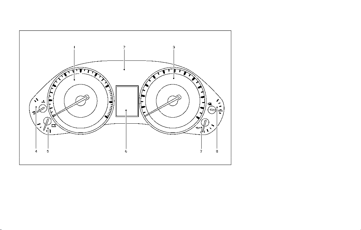
1. Tachometer (P.2-7)
2. Warning and indicator lights (P.2-10)
3. Speedometer (P.2-6)
4. Engine coolant temperature gauge (P.2-7)
5. Voltmeter (P.2-9)
6. Vehicle information display (P.2-20)/Od-
ometer/twin trip odometer (P.2-6)
7. Engine oil pressure gauge (P.2-8)
8. Fuel gauge (P.2-8)
METERS AND GAUGES
JVC0965X
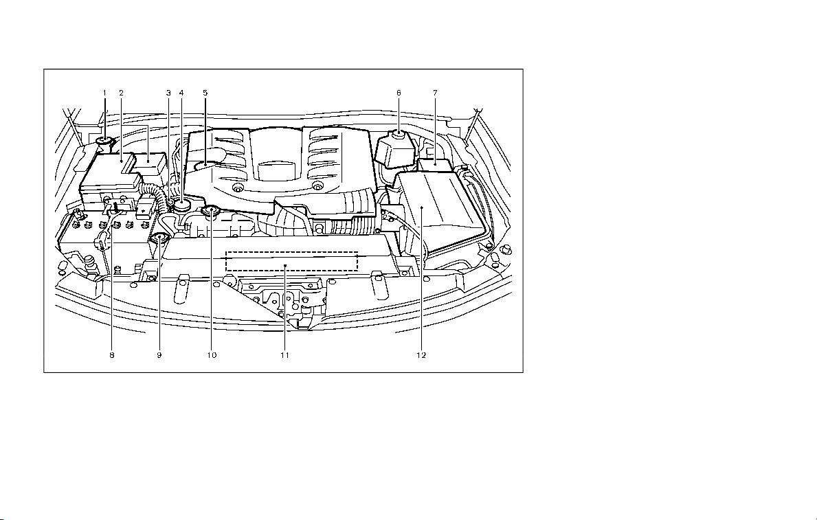
VK56VD ENGINE
1. Window washer fluid reservoir (P.8-10)
2. Fuse/fusible link holder (P.8-18)
3. Engine oil dipstick (P.8-6)
4. Power steering fluid reservoir (P.8-8)
5. Engine oil filler cap (P.8-6)
6. Brake fluid reservoir (P.8-9)
7. Fuse/fusible link holder (P.8-18)
8. Battery (P.8-11)
9. Radiator filler cap (P.8-4)
10. Engine coolant reservoir (P.8-4)
11. Drive belts (P.8-13)
12. Air cleaner (P.8-15)
Illustrated table of contents 0-9
ENGINE COMPARTMENT
0-10 Illustrated table of contents
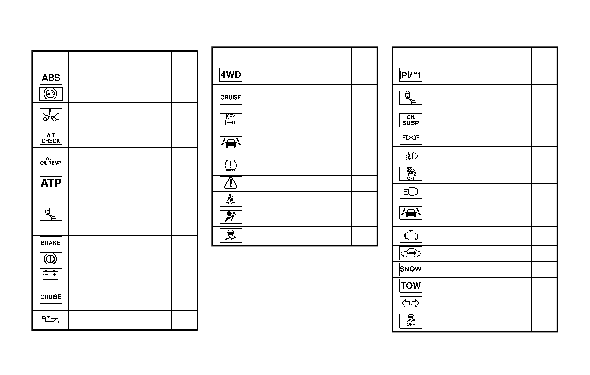
Warning
light
Name
Page
Anti-lock Braking System
(ABS) warning light
2-11
Automatic Emergency
Braking (AEB) system
warning light
2-11
Automatic Transmission
(AT) check warning light
2-11
Automatic Transmission
(AT) oil temperature warn-
ing light
2-11
Automatic Transmission
(AT) park warning light
2-12
Blind Spot Warning (BSW)/
Intelligent Blind Spot Inter-
vention (I-BSI) system
warning light (orange; if so
equipped)
2-12
Brake warning light
2-12
Charge warning light
2-13
Intelligent Distance Control
(I-DC) system warning light
(orange; if so equipped)
2-13
Engine oil pressure warning
light
2-13
Warning
light
Name
Page
Four-Wheel Drive (4WD)
warning light (4WD models)
2-14
Intelligent Cruise Control
(ICC) system warning light
(orange)
2-14
Intelligent Key warning
light
2-14
Lane Departure Warning
(LDW) indicator light (or-
ange; if so equipped)
2-14
Low tire pressure warning
light
2-15
Master warning light
2-16
Seat belt warning light
2-16
Supplemental air bag
warning light
2-17
Vehicle Dynamic Control
(VDC) warning light
2-17
Indica-
tor light
Name
Page
Automatic Transmission
(AT) position indicator light
2-18
Intelligent Blind Spot Inter-
vention (I-BSI) ON indicator
light (green; if so equipped)
2-18
Check suspension indicator
light
2-18
Exterior light indicator
2-18
Front fog light indicator
light (if so equipped)
2-18
Front passenger air bag
status light
2-18
High beam indicator light
2-18
Intelligent Lane Interven-
tion (I-LI) ON indicator light
(green; if so equipped)
2-18
Malfunction Indicator Light
(MIL)
2-18
Security indicator light
2-19
SNOW mode indicator light
2-19
TOW mode indicator light
2-19
Turn signal/hazard indica-
tor lights
2-19
Vehicle Dynamic Control
(VDC) off indicator light
2-20
WARNING AND INDICATOR LIGHTS

1 Safety — seats, seat belts and supple-
mental restraint system
Seats ....................................................................................................... 1-3
Front seats .................................................................................. 1-4
2nd row seats .......................................................................... 1-5
3rd row seats ........................................................................... 1-7
Armrest ....................................................................................... 1-11
Flexible seating ..................................................................... 1-12
Head restraints/headrests ................................................. 1-14
Adjustable head
restraint/headrest components ............................. 1-16
Non-adjustable head
restraint/headrest components ............................. 1-16
Remove ....................................................................................... 1-16
Install............................................................................................. 1-17
Adjust............................................................................................ 1-17
Front-seat Active Head Restraint .......................... 1-19
Seat belts ......................................................................................... 1-20
Precautions on seat belt usage .............................. 1-20
Pregnant women ................................................................ 1-22
Injured persons ..................................................................... 1-22
Three-point type seat belt .......................................... 1-22
Seat belt extenders ........................................................... 1-29
Seat belt maintenance ................................................... 1-29
Child safety ..................................................................................... 1-30
Infants .......................................................................................... 1-31
Small children ........................................................................ 1-31
Larger children ................................................................... 1-31
Child restraints ........................................................................... 1-32
Precautions on child restraints ............................. 1-33
Lower Anchors and Tethers for CHildren
(LATCH) system ................................................................ 1-35
Top tether strap child restraint ............................ 1-37
Rear-facing child restraint installation
using LATCH ......................................................................... 1-38
Rear-facing child restraint installation
using the seat belts ........................................................ 1-40
Forward-facing child restraint installation
using LATCH ......................................................................... 1-43
Forward-facing child restraint installation
using the seat belts ........................................................ 1-46
Booster seats ....................................................................... 1-51
Supplemental restraint system ..................................... 1-54
Precautions on supplemental
restraint system ................................................................ 1-54
NISSAN Advanced Air Bag System
(front seats) ........................................................................... 1-60
Front seat-mounted side-impact
supplemental air bag and roof-mounted
curtain side-impact and rollover
supplemental air bag systems .............................. 1-68
Seat belts with pretensioners
(front seats) ........................................................................... 1-69

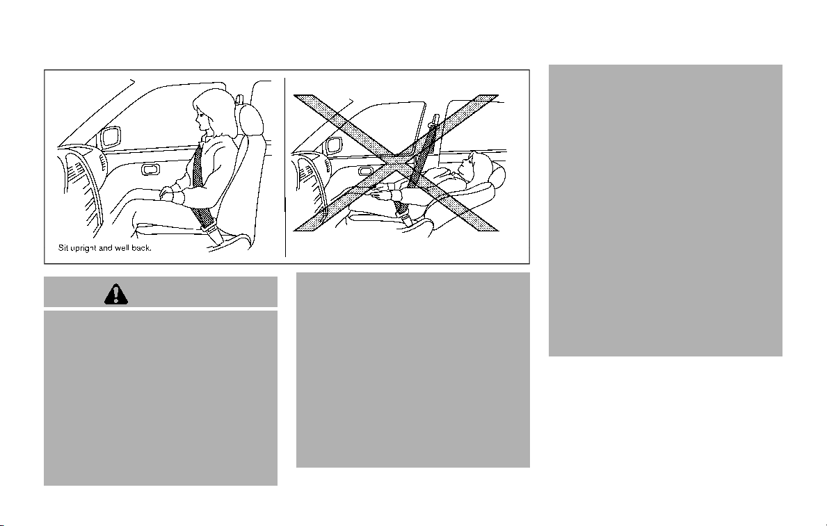
SSS0133
WARNING
. Do not ride in a moving vehicle
when the seatback is reclined.
This can be dangerous. The
shoulder belt will not be against
your body. In an accident, you
could be thrown into it and re-
ceive neck or other serious inju-
ries. You could also slide under
the lap belt and receive serious
internal injuries.
. For the most effective protection
when the vehicle is in motion, the
seat should be upright. Always sit
well back and upright in the seat
with both feet on the floor and
adjust the seat belt properly. See
“Precautions on seat belt usage”
(P.1-20).
. After adjustment, gently rock in
the seat to make sure it is se-
curely locked.
. Do not leave children unattended
inside the vehicle. They could
unknowingly activate switches
or controls. Unattended children
could become involved in serious
accidents.
. To help avoid risk of injury or
death through unintended opera-
tion of the vehicle and/or its
systems, do not leave children,
people who require the assis-
tance of others or pets unat-
tended in your vehicle.
Additionally, the temperature in-
side a closed vehicle on a warm
day can quickly become high
enough to cause a significant risk
of injury or death to people and
pets.
. The seatback should not be re-
clined any more than needed for
comfort. Seat belts are most ef-
fective when the passenger sits
well back and straight up in the
seat. If the seatback is reclined,
the risk of sliding under the lap
belt and being injured is in-
creased.
Safety — seats, seat belts and supplemental restraint system 1-3
SEATS
1-4 Safety — seats, seat belts and supplemental restraint system
FRONT SEATS
Front power seat adjustment
Operating tips:
. The power seat motor has an auto-
reset overload protection circuit. If the
motor stops during operation, wait 30
seconds, then reactivate the switch.
. Do not operate the power seat switch
for a long period of time when the
engine is off. This will discharge the
battery.
See “Automatic drive positioner” (P.3-40)
for the seat position memory function.
CAUTION
When adjusting the seat positions,
be sure not to contact any moving
parts to avoid possible injuries and/
or damages.
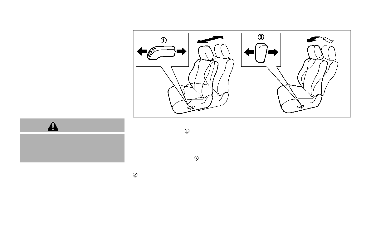
SSS1051
Forward and backward:
Moving the switch
forward or back-
ward will slide the seat forward or back-
ward to the desired position.
Reclining:
Move the recline switch
backward until
the desired angle is obtained. To bring the
seatback forward again, move the switch
forward.
The reclining feature allows adjustment
of the seatback for occupants of different
sizes for added comfort and to help
obtain proper seat belt fit. (See “Precau-
tions on seat belt usage” (P.1-20).) Also,
the seatback can be reclined to allow
occupants to rest when the vehicle is
stopped and the transmission is in the P
(Park) position.
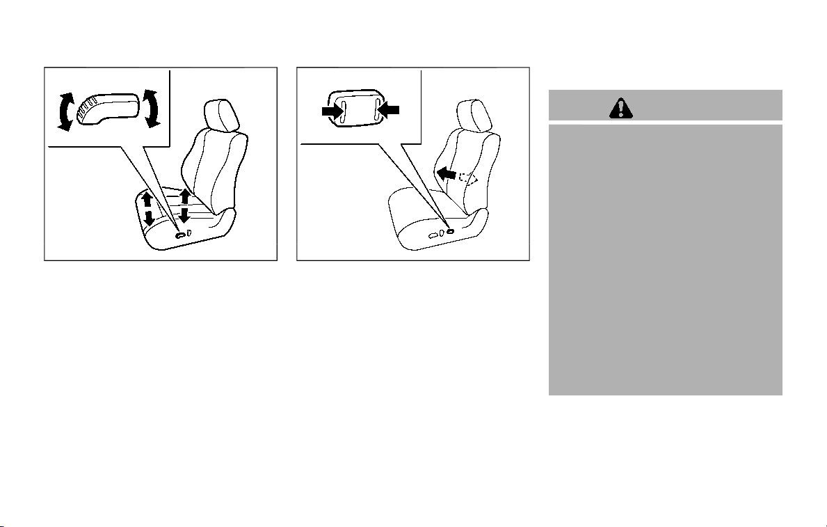
SSS1052
Seat lifter:
1. Pull up or push down the adjusting
switch to adjust the seat height until
the desired position is achieved.
2. Tilt up or down the adjusting switch to
adjust the front angle of the seat until
the desired position is achieved (for
driver’s seat).
SSS1053
Lumbar support:
The lumbar support feature provides low-
er back support to the occupants.
Push the front or back end of the switch
to adjust the seatback lumbar area.
2ND ROW SEATS
WARNING
. Never allow anyone to ride in the
cargo area or on the rear seat
when it is in the fold-down posi-
tion. Use of these areas by pas-
sengers without proper restraints
could result in serious injury in an
accident or sudden stop.
. When returning the seatbacks to
the upright position, be certain
they are completely secured in
the latched position. If they are
not completely secured, passen-
gers may be injured in an acci-
dent or sudden stop.
. Properly secure all cargo to help
prevent it from sliding or shifting.
Do not place cargo higher than
the seatbacks. In a sudden stop
or collision, unsecured cargo
could cause personal injury.
Safety — seats, seat belts and supplemental restraint system 1-5
1-6 Safety — seats, seat belts and supplemental restraint system
SSS1081
Captain’s seat
SSS1065
Bench seat
Reclining
Pull the reclining lever and position the
seatback at the desired angle. Release the
reclining lever after positioning the seat
at the desired angle.
To return the seatback, pull the lever.
The reclining feature allows adjustment
of the seatback for occupants of different
sizes to help obtain proper seat belt fit.
(See “Precautions on seat belt usage” (P.1-
20).) The seatback may also be reclined to
allow occupants to rest when the vehicle
is parked.
WARNING
. Do not ride in a moving vehicle
when the seatback is reclined.
This can be dangerous. The
shoulder belt will not be against
your body. In an accident, you
could be thrown into it and re-
ceive neck or other serious inju-
ries. You could also slide under
the lap belt and receive serious
internal injuries.
. For the most effective protection
when the vehicle is in motion, the
seat should be upright. Always sit
well back and upright in the seat
with both feet on the floor and
adjust the seat belt properly. See
“Precautions on seat belt usage”
(P.1-20).
. After adjustment, check to be
sure the seat is securely locked.
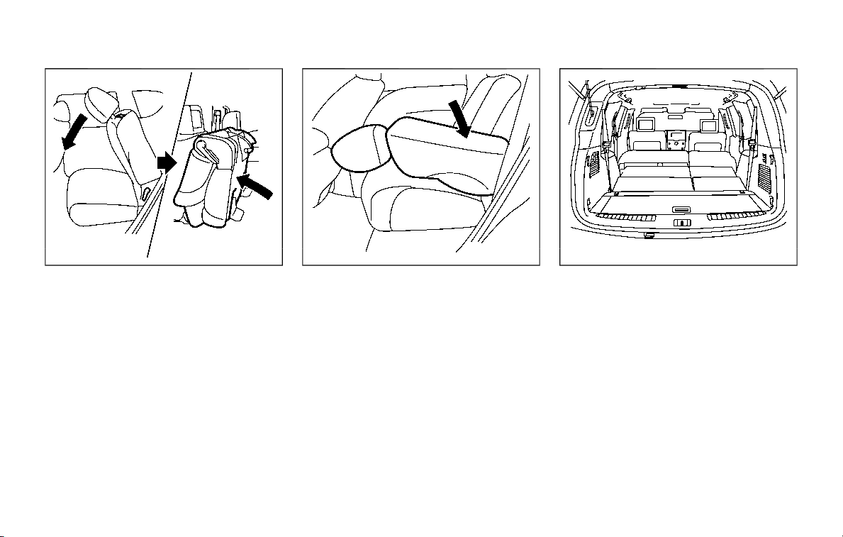
Entry to 3rd row seat
CAUTION
. Do not drive with the 2nd row
seat tipped up.
. Be careful not to allow the 2nd
row seat to pinch, hit any part of
your body or other people when
operating the 2nd row seat. Make
sure the seat path is clear of all
objects before moving the seat.
The 2nd row seat can be tipped forward
for easy entry to or exit from the 3rd row
seat.
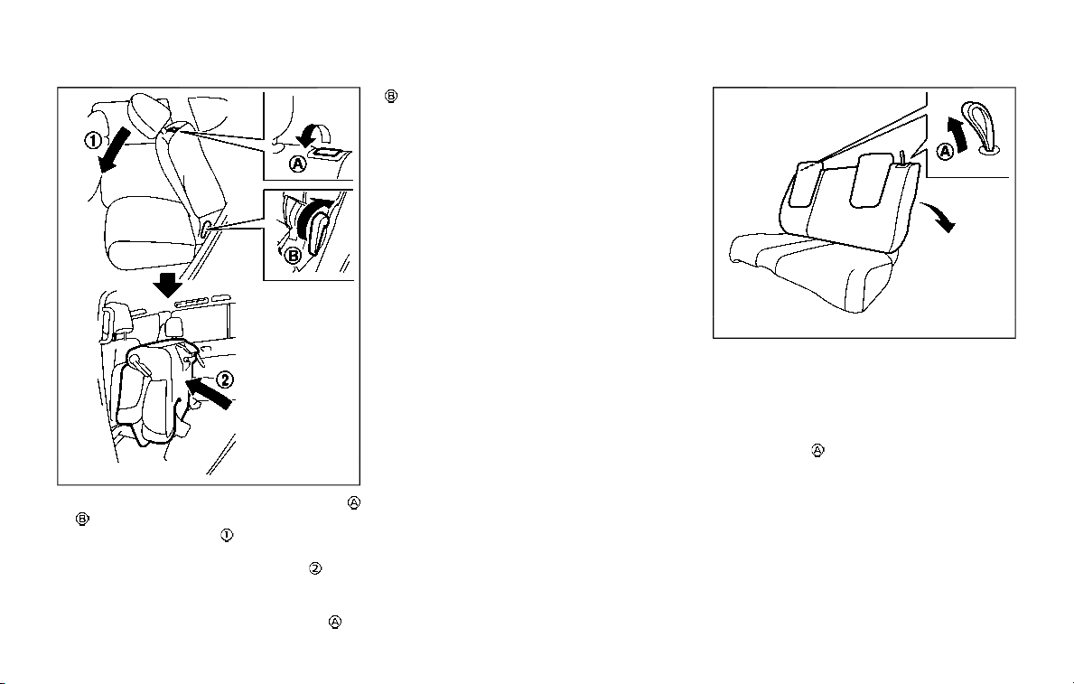
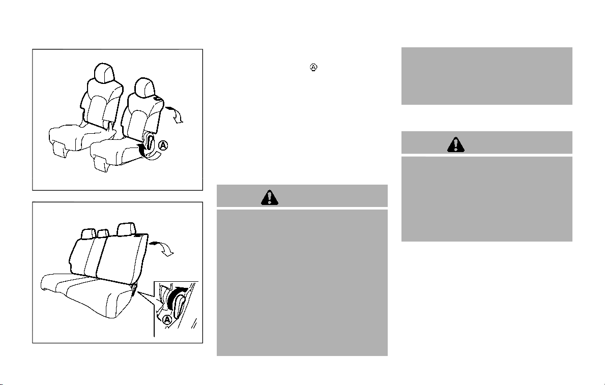
SSS1066
To enter the 3rd row seat, pull the lever
or located on the 2nd row seat and fold
the seatback forward
at an angle over
the seat base. Then lift up the seat base
and tip the 2nd row seat forward
. This
will release the back of the seat so it may
be tipped forward.
To exit the 3rd row seat, pull the lever
or
and fold the seatback forward onto the
seat base. Then lift up on the seat base
and tip it forward.
SSS1068
3RD ROW SEATS
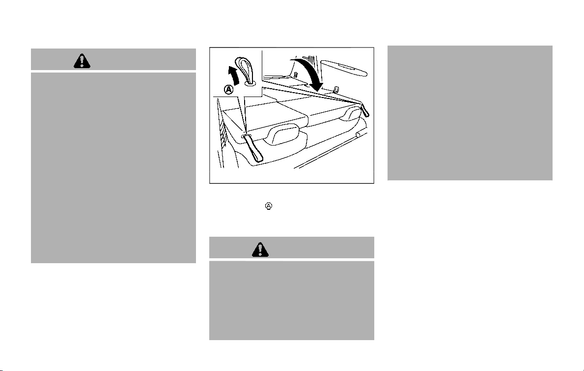
Manual seat adjustment (if so
equipped)
Reclining:
Pull the strap
and position the seatback
at the desired angle. Release the strap
after positioning the seat at the desired
angle.
The reclining feature allows adjustment
of the seatback for occupants of different
sizes to help obtain proper seat belt fit.
(See “Precautions on child restraints” (P.1-
33).) The seatback may also be reclined to
allow occupants to rest when the vehicle
is parked.
Safety — seats, seat belts and supplemental restraint system 1-7
1-8 Safety — seats, seat belts and supplemental restraint system
WARNING
. Do not ride in a moving vehicle
when the seatback is reclined.
This can be dangerous. The
shoulder belt will not be against
your body. In an accident, you
could be thrown into it and re-
ceive neck or other serious inju-
ries. You could also slide under
the lap belt and receive serious
internal injuries.
. For the most effective protection
when the vehicle is in motion, the
seat should be upright. Always sit
well back and upright in the seat
with both feet on the floor and
adjust the seat belt properly. See
“Precautions on seat belt usage”
(P.1-20).
. After adjustment, check to be
sure the seat is securely locked.
SSS1069
Folding:
Pull the strap
and fold the seatback.
Return the seatback until it securely locks
in position.
WARNING
. Never allow anyone to ride in the
cargo area or on the third row
seat when it is in the folddown
position. Use of these areas by
passengers without proper re-
straints could result in serious
injury in an accident or sudden
stop.
. Properly secure all cargo with
ropes or straps to help prevent it
from sliding or shifting. Do not
place cargo higher than the seat-
backs. In a sudden stop or colli-
sion, unsecured cargo could
cause personal injury.
. When returning the seatbacks to
the upright position, be certain
they are completely secured in
the latched position. If they are
not completely secured, passen-
gers may be injured in an acci-
dent or sudden stop.

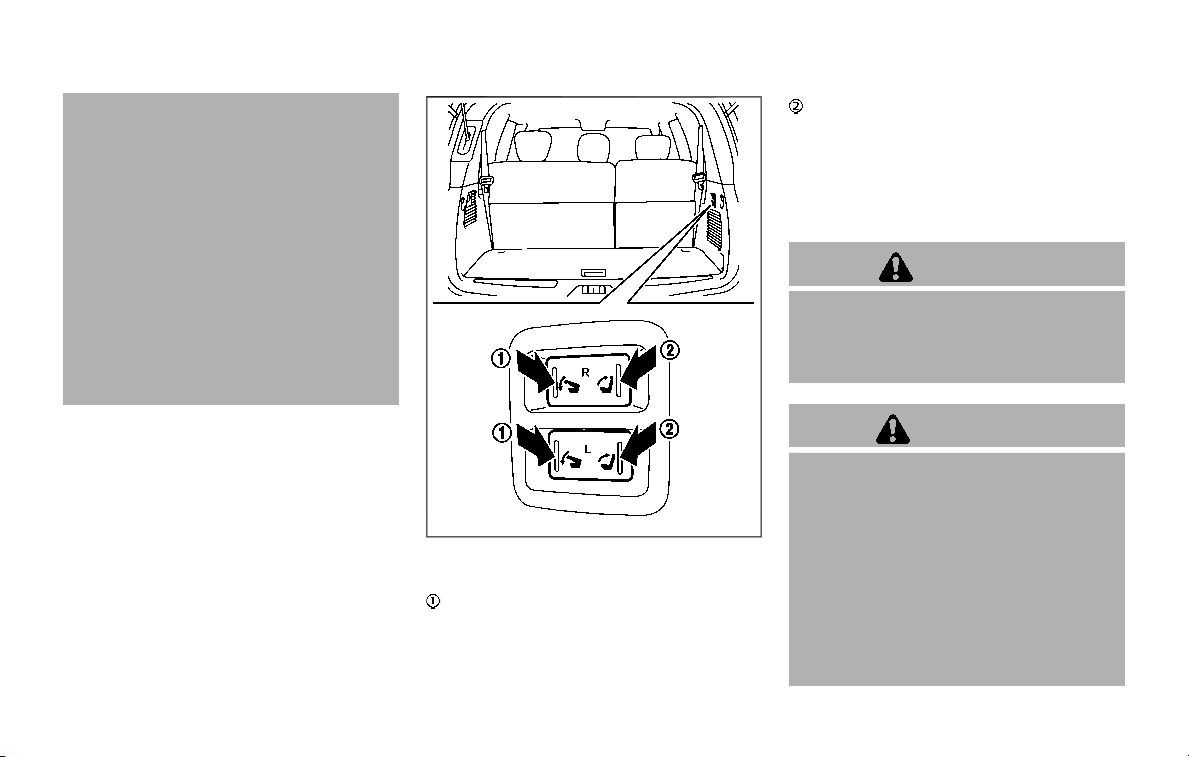
SSS1116
Power seat adjustment (if so
equipped)
The 3rd row power folding seat controls
are located behind the 2nd row seat (both
the driver’s and front passenger’s side) on
the 3rd row cup holder console
. There
are also controls located on the rear
quarter trim panel behind the 3rd row
seats (passenger’s side)
.
Before operating the 3rd row seats:
. Make sure the 2nd row seatback is not
reclined.
. Lower the 3rd row head restraint to
the full down position.
. Disconnect and secure the center seat
belt and tongues into the retractor
base. See “3rd row center seat belt”
(P.1-26).
— Always reconnect the center seat
belt when the seat is returned to
the upright position
. Make sure that there are no objects
on the seatback cushion.
SSS1095
Reclining:
Push and hold the rear side of the switch
beside the 3rd row cup holders until the
desired seatback angle (up to 20 degrees)
is obtained. To move the seatback for-
ward again, push and hold the front side
of the switch
until the desired angle is
obtained.
WARNING
. After adjustment, check to be
sure the seat is securely locked.
. Do not ride in a moving vehicle
when the seatback is reclined.
Safety — seats, seat belts and supplemental restraint system 1-9
1-10 Safety — seats, seat belts and supplemental restraint system
This can be dangerous. The
shoulder belt will not be against
your body. In an accident, you
could be thrown into it and re-
ceive neck or other serious inju-
ries. You could also slide under
the lap belt and receive serious
internal injuries.
. For the most effective protection
when the vehicle is in motion, the
seat should be upright. Always sit
well back and upright in the seat
with both feet on the floor and
adjust the seat belt properly. See
“Precautions on seat belt usage”
(P.1-20).
SSS1118
Folding:
Push and hold the front side of the switch
located on the passenger side of the
cargo room. The corresponding seatback
(R: right side, L: left side) will be folded
down automatically.
Push and hold the rear side of the switch
. The seatback will be returned auto-
matically. The seatback will rise up while
holding the switch.
NOTE:
Operating the power folding seats can
discharge the vehicle battery if the
engine is not running.
CAUTION
When operating the rear power seat-
back return, make sure that the
vehicle is stopped and the transmis-
sion is in the P (Park) position.
WARNING
. Never allow anyone to ride in the
cargo area or on the rear seat
when it is in the fold-down posi-
tion. Use of these areas by pas-
sengers without proper restraints
could result in serious injury in an
accident or sudden stop.
. When returning the seatbacks to
the upright position, be certain
they are completely secured in
the latched position. If they are
not completely secured, passen-
gers may be injured in an acci-
dent or sudden stop.
. Properly secure all cargo to help
prevent it from sliding or shifting.
Do not place cargo higher than
the seatbacks. In a sudden stop
or collision, unsecured cargo
could cause personal injury.
JVR0557X
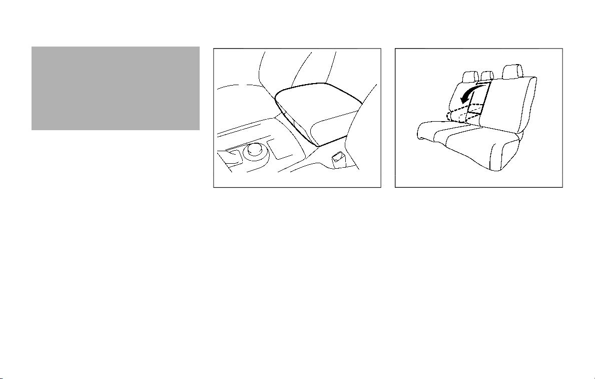
ARMREST
Front seats
The console box lid can be used as an
armrest.
SSS1070
2nd row seat (if so equipped)
Pull and draw the armrest forward until it
is horizontal.
Safety — seats, seat belts and supplemental restraint system 1-11

1-12 Safety — seats, seat belts and supplemental restraint system
FLEXIBLE SEATING
WARNING
. Never allow anyone to ride in the
cargo area or on the rear seats
when they are in the fold-down
position. In a collision, people
riding in these areas without
proper restraints are more likely
to be seriously injured or killed.
. Do not allow people to ride in any
area of your vehicle that is not
equipped with seats and seat
belts. Be sure everyone in your
vehicle is in a seat and using a
seat belt properly.
. Do not fold down the rear seats
when occupants are in the rear
seat area or any cargo is on the
rear seats.
. Head restraints should be ad-
justed properly as they may pro-
vide significant protection
against injury in an accident. Al-
ways replace and adjust them
properly if they have been re-
moved for any reason.
. If the head restraints are re-
moved for any reason, they
should be securely stored to pre-
vent them from causing injury to
passengers or damage to the
vehicle in case of sudden braking
or an accident.
. When returning the seatbacks to
the upright position, be certain
they are completely secured in
the latched position. If they are
not completely secured, passen-
gers may be injured in an acci-
dent or sudden stop.
. Properly secure all cargo to help
prevent it from sliding or shifting.
Do not place cargo higher than
the seatbacks. In a sudden stop
or collision, unsecured cargo
could cause personal injury.
. When folding the bench seat
seatback down for maximum sto-
rage, make sure the seat base is
in the latched position by rocking
the seat base. If the seat base is
not properly secured, cargo
stored on top of a folded seat-
back may become a projectile
causing personal injury or vehicle
damage.
CAUTION
. When folding the 2nd row seat for
maximum cargo hauling, be sure
that cargo does not contact the
center console of the captain’s
seat (if so equipped) to avoid
possible damage to the console.
. When folding or returning the
seat(s) to the upright position, to
avoid injury to yourself and
others:
— Make sure that the seat path
is clear before moving the
seat.
— Be careful not to allow hands
or feet to get caught or
pinched in the seat.
Stowing 2nd and 3rd row seats
To stow 2nd and 3rd row seats for
maximum cargo capacity:
SSS1119
1. Push and hold the corresponding
switch located on the instrument
panel below the audio system. The
seatback will fold down and tip for-
ward. See “Entry to 3rd row seat” (P.1-
6).
SSS1120
2. Push the folded seat down until it
locks in position.
SSS1121
3. Power operation (if so equipped): Fold
the 3rd row seat flat using the
switches located in the cargo area.
See “Power seat adjustment” (P.1-9).
Manual operation (if so equipped):
Fold the 3rd row seat flat using the
strap located on the 3rd row seat-
backs. See “Manual seat adjustment”
(P.1-7).
4. Return 3rd row seats to seating posi-
tions by raising the 3rd row seatbacks
to an upright position using the
switches or straps. Make sure the
seatback is locked in position. See
“Power seat adjustment” (P.1-9) or
“Manual seat adjustment” (P.1-7).
Safety — seats, seat belts and supplemental restraint system 1-13

1-14 Safety — seats, seat belts and supplemental restraint system
5. Return the 2nd row seat to a seating
position by raising the 2nd row seat-
backs to an upright position. Make
sure the seatback is locked in position.
CAUTION
When folding the 2nd row seat for
maximum cargo hauling, be sure
that cargo does not contact the
center console of the captain’s seat
(if so equipped) to avoid possible
damage to the console.
WARNING
Head restraint/headrest supplement
the other vehicle safety systems.
They may provide additional protec-
tion against injury in certain rear end
collisions. Adjustable head re-
straints/headrests must be adjusted
properly, as specified in this section.
Check the adjustment after someone
else uses the seat. Do not attach
anything to the head restraint/head-
rest stalks or remove the head re-
straint/headrest. Do not use the seat
if the head restraint/headrest has
been removed. If the head restraint/
headrest was removed, reinstall and
properly adjust the head restraint/
headrest before an occupant uses
the seating position. Failure to follow
these instructions can reduce the
effectiveness of the head restraint/
headrest. This may increase the risk
of serious injury or death in a colli-
sion.
HEAD RESTRAINTS/HEADRESTS
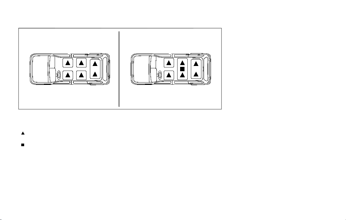
JVR0403X
The illustration shows the seating posi-
tions equipped with head restraint/head-
rest.
Indicates the seating position is
equipped with a head restraint.
Indicates the seating position is
equipped with a headrest.
. Your vehicle is equipped with a head
restraint/headrest that may be inte-
grated, adjustable or non-adjustable.
. Adjustable head restraints/headrests
have multiple notches along the stalk
to lock them in a desired adjustment
position.
. The non-adjustable head restraints/
headrests have a single locking notch
to secure them to the seat frame.
. Proper Adjustment:
— For the adjustable type, align the
head restraint/headrest so the
center of your ear is approximately
level with the center of the head
restraint/headrest.
— If your ear position is still higher
than the recommended alignment,
place the head restraint/headrest
at the highest position.
. If the head restraint/headrest has
been removed, ensure that it is re-
installed and locked in place before
riding in that designated seating posi-
tion.
Safety — seats, seat belts and supplemental restraint system 1-15
1-16 Safety — seats, seat belts and supplemental restraint system
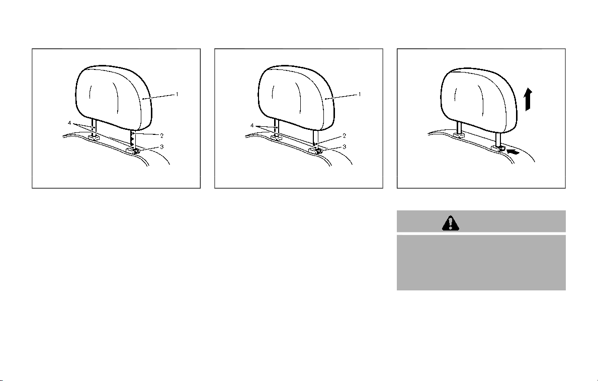
SSS0992
ADJUSTABLE HEAD RESTRAINT/
HEADREST COMPONENTS
1. Removable head restraint/headrest
2. Multiple notches
3. Lock knob
4. Stalks
JVR0203X
NON-ADJUSTABLE HEAD RE-
STRAINT/HEADREST COMPONENTS
1. Removable head restraint/headrest
2. Single notch
3. Lock knob
4. Stalks
SSS1037
REMOVE
CAUTION
The front head restraints with a rear
display are not designed to be pulled
out. The rear display may be da-
maged if the head restraint is for-
cibly pulled out.
Use the following procedure to remove
the head restraint/headrest.
1. Pull the head restraint/headrest up to
the highest position.
2. Push and hold the lock knob.
3. Remove the head restraint/headrest
from the seat.
4. Store the head restraint/headrest
properly in a secure place so it is not
loose in the vehicle.
5. Reinstall and properly adjust the head
restraint/headrest before an occu-
pant uses the seating position.
SSS0996
INSTALL
1. Align the head restraint/headrest
stalks with the holes in the seat. Make
sure that the head restraint/headrest
is facing the correct direction. The
stalk with the adjustment notch
must be installed in the hole with the
lock knob
.
2. Push and hold the lock knob and push
the head restraint/headrest down.
3. Properly adjust the head restraint/
headrest before an occupant uses
the seating position.
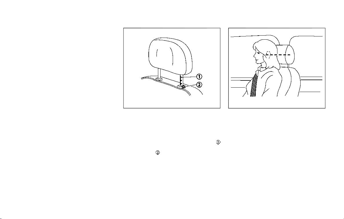
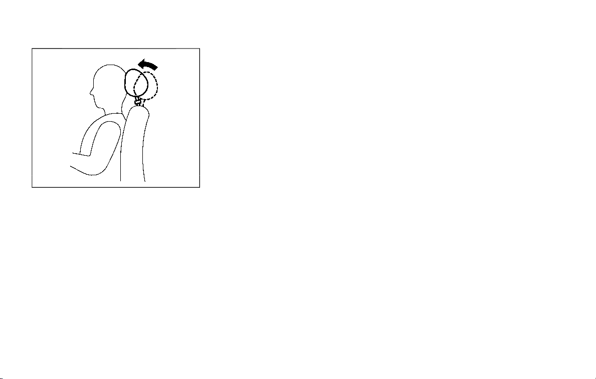
SSS0997
ADJUST
For adjustable head restraint/headrest
Adjust the head restraint/headrest so the
center is level with the center of your ears.
If your ear position is still higher than the
recommended alignment, place the head
restraint/headrest at the highest posi-
tion.
Safety — seats, seat belts and supplemental restraint system 1-17
1-18 Safety — seats, seat belts and supplemental restraint system
JVR0259X
For non-adjustable head restraint/
headrest
Make sure the head restraint/headrest is
positioned so the lock knob is engaged in
the notch before riding in that designated
seating position.
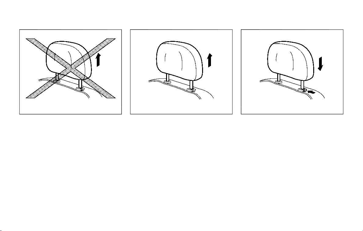
SSS1035
Raise
To raise the head restraint/headrest, pull
it up.
Make sure the head restraint/headrest is
positioned so the lock knob is engaged in
the notch before riding in that designated
seating position.
SSS1036
Lower
To lower, push and hold the lock knob
and push the head restraint/headrest
down.
Make sure the head restraint/headrest is
positioned so the lock knob is engaged in
the notch before riding in that designated
seating position.
SSS0508
FRONT-SEAT ACTIVE HEAD RE-
STRAINT
The Active Head Restraint moves forward
utilizing the force that the seatback
receives from the occupant in a rear-end
collision. The movement of the head
restraint helps support the occupant’s
head by reducing its backward move-
ment and helping absorb some of the
forces that may lead to whiplash-type
injuries.
Active Head Restraints are effective for
collisions at low to medium speeds in
which it is said that whiplash injury occurs
most.
Active Head Restraints operate only in
certain rear-end collisions. After the colli-
sion, the head restraints return to their
original position.
Adjust the Active Head Restraints prop-
erly as described earlier in this section.
Safety — seats, seat belts and supplemental restraint system 1-19
1-20 Safety — seats, seat belts and supplemental restraint system
PRECAUTIONS ON SEAT BELT
USAGE
If you are wearing your seat belt properly
adjusted, and you are sitting upright and
well back in your seat with both feet on
the floor, your chances of being injured or
killed in an accident and/or the severity of
injury may be greatly reduced. NISSAN
strongly encourages you and all of your
passengers to buckle up every time you
drive, even if your seating position in-
cludes a supplemental air bag.
Most U.S. states and Canadian pro-
vinces or territories specify that seat
belts be worn at all times when a
vehicle is being driven.
SSS0136A
SSS0134A
SEAT BELTS

WARNING
. Every person who drives or rides
in this vehicle should use a seat
belt at all times. Children should
be properly restrained in the rear
seat and, if appropriate, in a child
restraint.
. The seat belt should be properly
adjusted to a snug fit. Failure to
do so may reduce the effective-
ness of the entire restraint sys-
tem and increase the chance or
severity of injury in an accident.
Serious injury or death can occur
if the seat belt is not worn prop-
erly.
. Always route the shoulder belt
over your shoulder and across
your chest. Never put the belt
behind your back, under your
arm or across your neck. The belt
should be away from your face
and neck, but not falling off your
shoulder.
. Position the lap belt as low and
snug as possible AROUND THE
HIPS, NOT THE WAIST. A lap belt
worn too high could increase the
risk of internal injuries in an
accident.
. Be sure the seat belt tongue is
securely fastened to the proper
buckle.
. Do not wear the seat belt inside
out or twisted. Doing so may
reduce its effectiveness.
. Do not allow more than one
person to use the same seat belt.
. Never carry more people in the
vehicle than there are seat belts.
. If the seat belt warning light
glows continuously while the
ignition is turned ON with all
doors closed and all seat belts
fastened, it may indicate a mal-
function in the system. Have the
system checked. It is recom-
mended you visit a NISSAN dealer
for this service.
. No changes should be made to
the seat belt system. For exam-
ple, do not modify the seat belt,
add material or install devices
that may change the seat belt
routing or tension. Doing so may
affect the operation of the seat
belt system. Modifying or tam-
pering with the seat belt system
may result in serious personal
injury.
. Once a seat belt pretensioner has
activated, it cannot be reused and
must be replaced together with
the retractor. It is recommended
you visit a NISSAN dealer for this
service.
. All seat belt assemblies, including
retractors and attaching hard-
ware, should be inspected after
any collision. It is recommended
you visit a NISSAN dealer for this
service. NISSAN recommends that
all seat belt assemblies in use
during a collision be replaced
unless the collision was minor
and the belts show no damage
and continue to operate properly.
Seat belt assemblies not in use
during a collision should also be
inspected and replaced if either
damage or improper operation is
noted.
. All child restraints and attaching
hardware should be inspected
after any collision. Always follow
the restraint manufacturer’s in-
spection instructions and repla-
cement recommendations. The
child restraints should be re-
placed if they are damaged.
Safety — seats, seat belts and supplemental restraint system 1-21
1-22 Safety — seats, seat belts and supplemental restraint system
SSS0016
SSS0014
PREGNANT WOMEN
NISSAN recommends that pregnant wo-
men use seat belts. The seat belt should
be worn snug, and always position the lap
belt as low as possible around the hips,
not the waist, and place the shoulder belt
over your shoulder and across your chest.
Never run the lap/shoulder belt over your
abdominal area. Contact your doctor for
specific recommendations.
INJURED PERSONS
NISSAN recommends that injured persons
use seat belts, depending on the injury.
Check with your doctor for specific re-
commendations.
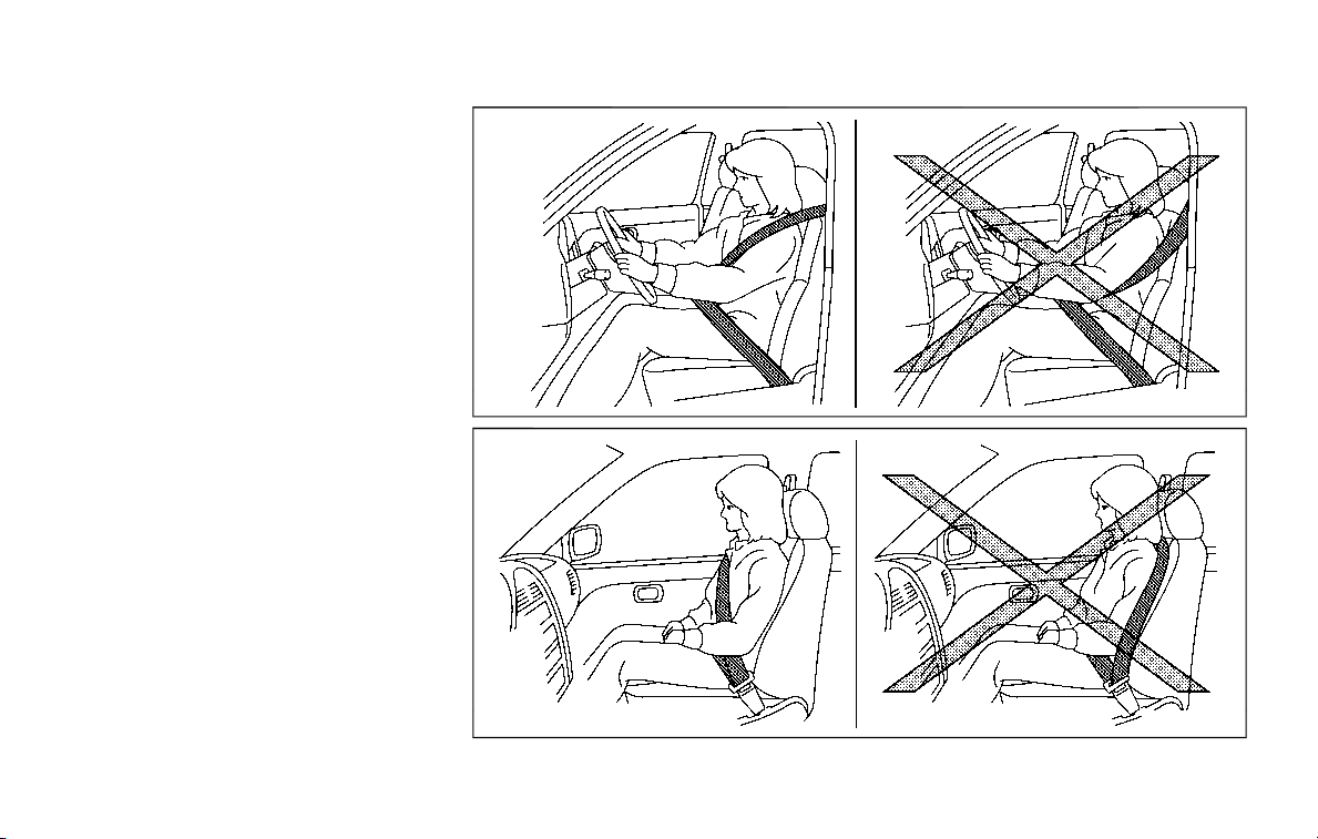
THREE-POINT TYPE SEAT BELT
WARNING
. Every person who drives or rides
in this vehicle should use a seat
belt at all times.
. Do not ride in a moving vehicle
when the seatback is reclined.
This can be dangerous. The
shoulder belt will not be against
your body. In an accident, you
could be thrown into it and re-
ceive neck or other serious inju-
ries. You could also slide under
the lap belt and receive serious
internal injuries.
. For the most effective protection
when the vehicle is in motion, the
seat should be upright. Always sit
well back and upright in the seat
with both feet on the floor and
adjust the seat belt properly.
JVR0183X
WARNING
Do not allow children to play with the
seat belts. Most seating positions are
equipped with Automatic Locking
Retractor (ALR) mode seat belts. If
the seat belt becomes wrapped
around a child’s neck with the ALR
mode activated, the child can be
seriously injured or killed if the seat
belt retracts and becomes tight. This
can occur even if the vehicle is
parked. Unbuckle the seat belt to
release the child. For the center of
the 3rd row bench seat, the connec-
tor tongue
may also be released.
Release the connector tongue by
inserting a suitable tool (such as a
key) into the connector buckle
.If
the seat belt cannot be unbuckled or
is already unbuckled, release the
child by cutting the seat belt with a
suitable tool (such as a knife or
scissors) to release the seat belt.
SSS0292
Fastening the seat belts
1. Adjust the seat. (See “Seats” (P.1-3).)
2. Slowly pull the seat belt out of the
retractor and insert the tongue into
the buckle until you hear and feel the
latch engage.
.
The retractor is designed to lock
during a sudden stop or on im-
pact. A slow pulling motion per-
mits the belt to move, and allows
you some freedom of movement
in the seat.
.
If the seat belt cannot be pulled
from its fully retracted position,
firmly pull the belt and release it.
Then smoothly pull the belt out of
Safety — seats, seat belts and supplemental restraint system 1-23
1-24 Safety — seats, seat belts and supplemental restraint system
the retractor.
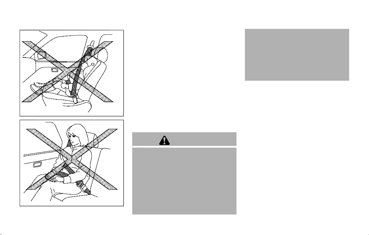
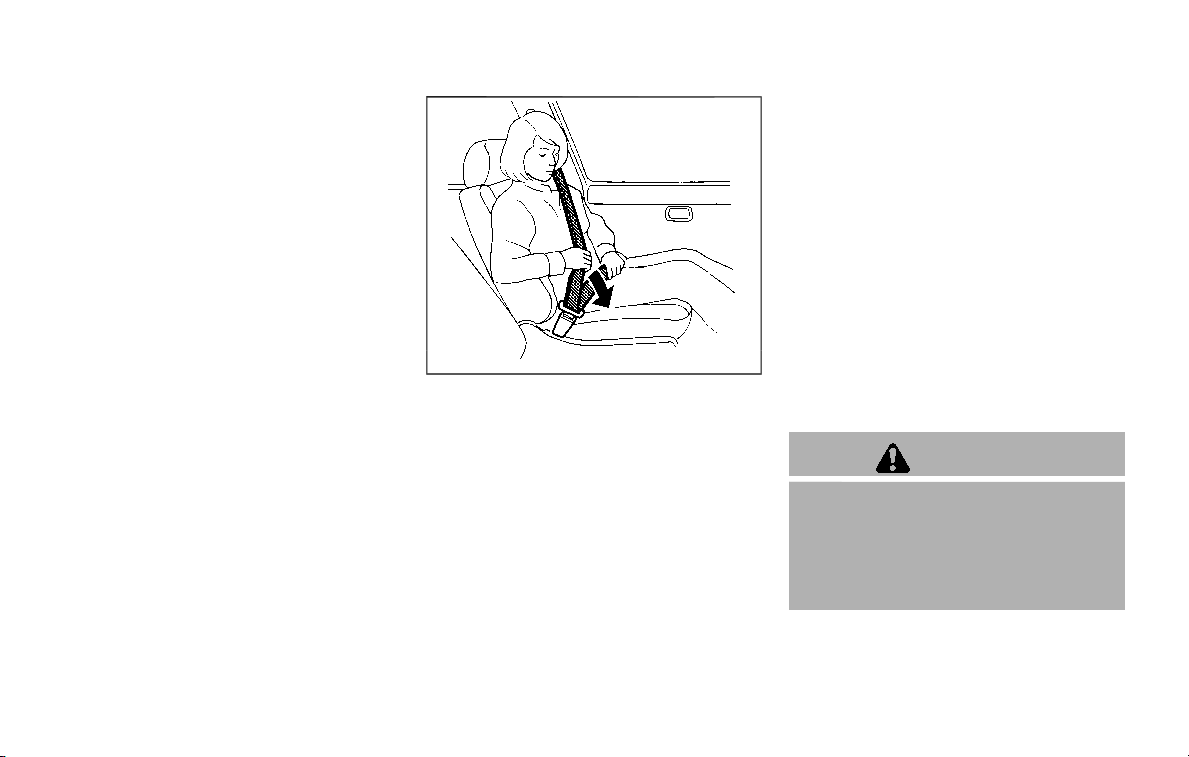
SSS0290
3. Position the lap belt portion low and
snug on the hips as shown.
4. Pull the shoulder belt portion toward
the retractor to take up extra slack. Be
sure the shoulder belt is routed over
your shoulder and across your chest.
The three-point type seat belts have two
modes of operation:
. Emergency Locking Retractor (ELR)
. Automatic Locking Retractor (ALR)
The Emergency Locking Retractor (ELR)
mode allows the seat belt to extend and
retract to allow the driver and passengers
some freedom of movement in the seat.
The ELR locks the seat belt when the
vehicle slows down rapidly or during
impacts.
The Automatic Locking Retractor (ALR)
mode (child restraint mode) locks the
seat belt for child restraint installation.
When the ALR mode is activated the seat
belt cannot be extended again until the
seat belt tongue is detached from the
buckle and fully retracted. The seat belt
returns to the ELR mode after the seat
belt fully retracts. For additional informa-
tion, see “Child restraints” (P.1-32).
The ALR mode should be used only for
child restraint installation. During nor-
mal seat belt use by an occupant, the
ALR mode should not be activated. If it
is activated, it may cause uncomforta-
ble seat belt tension.
WARNING
When fastening the seat belts, be
certain that seatbacks are comple-
tely secured in the latched position.
If they are not completely secured,
passengers may be injured in an
accident or sudden stop.
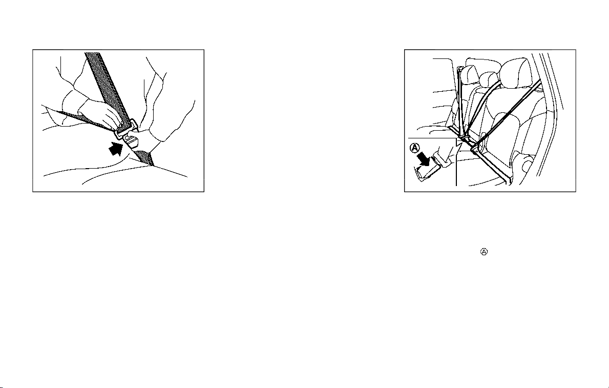
SSS0326
Unfastening the seat belts
To unfasten the seat belt, push the
button on the buckle. The seat belt
automatically retracts.
Checking seat belt operation
Seat belt retractors are designed to lock
seat belt movement by two separate
methods:
. When the belt is pulled quickly from
the retractor.
. When the vehicle slows down rapidly.
To increase your confidence in the seat
belts, check the operation as follows:
. Grasp the shoulder belt and pull for-
ward quickly. The retractor should
lock and restrict further belt move-
ment.
If the retractor does not lock during this
check, get the system checked. It is
recommended you visit a NISSAN dealer
for this service, or to learn more about
seat belt operation.
SSS1109
Center of 2nd row seat (if so
equipped)
Selecting correct set of seat belts:
The center seat belt buckle is identified by
the CENTER mark
. The center seat belt
tongue can be fastened only into the
center seat belt buckle.
Safety — seats, seat belts and supplemental restraint system 1-25
1-26 Safety — seats, seat belts and supplemental restraint system
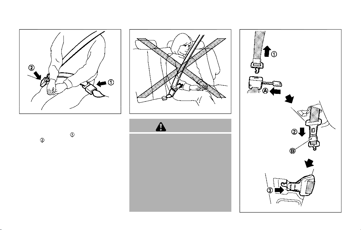
SSS0391
3rd row center seat belt
The 3rd row center seat belt has a
connector tongue
and a seat belt
tongue
. Both the connector tongue
and the seat belt tongue must be se-
curely latched for proper seat belt opera-
tion.
SSS0241
WARNING
. Always fasten the connector ton-
gue and the seat belt in the order
shown.
. Always make sure both the con-
nector tongue and the seat belt
tongue are secured when using
the seat belt or installing a child
restraint. Do not use the seat belt
or child restraint with only the
seat belt tongue attached. This
could result in serious personal
injury in case of an accident or a
sudden stop.
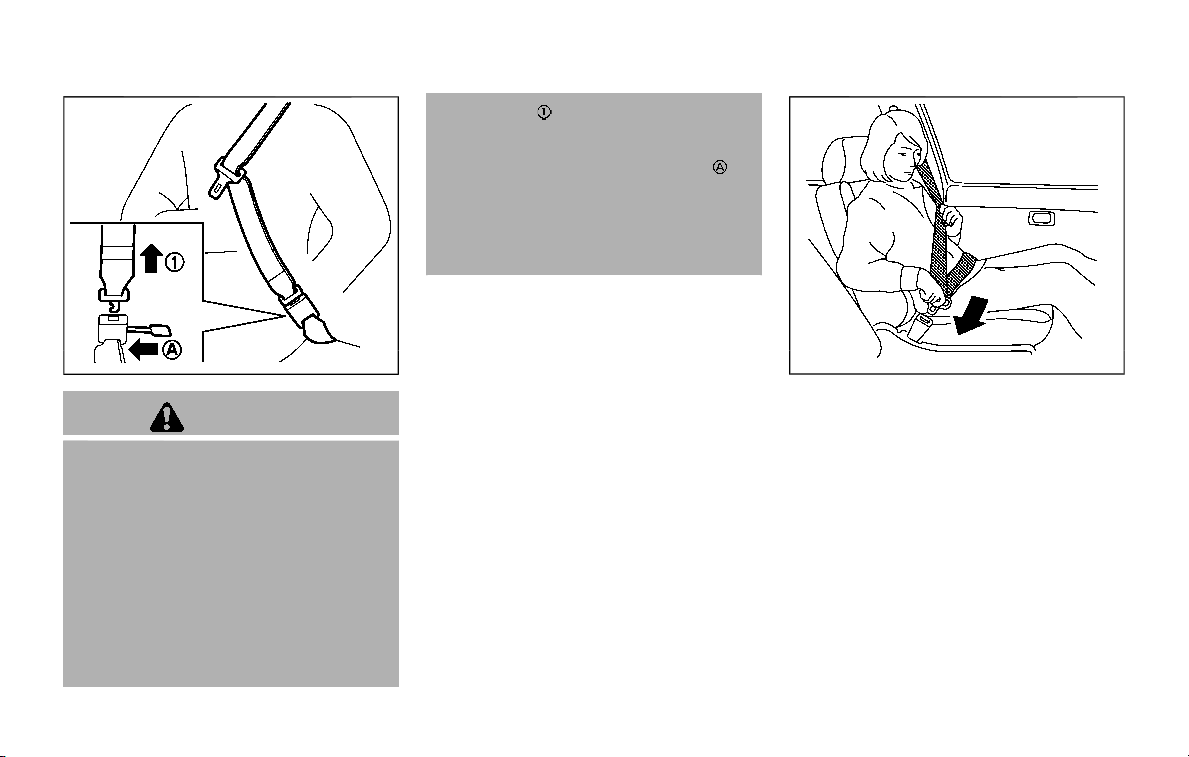
SSS1077
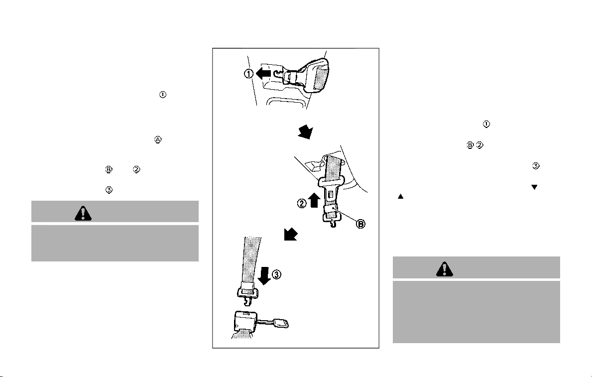
Stowing 3rd row center seat belt:
When folding down the 3rd row seat, the
3rd center seat belt can be retracted into
a stowed position.
1. Hold the connector tongue
so that
the seat belt does not retract sud-
denly when the tongue is released
from the connector buckle. Release
the connector tongue by inserting a
suitable tool such as key
into the
connector buckle.
2. Store the seat belt tongue into the
tongue holder
first .
3. Store the connector tongue into the
retractor base
.
WARNING
Do not unfasten the 3rd center seat
belt connector except when folding
down the 3rd seat.
SSS1078
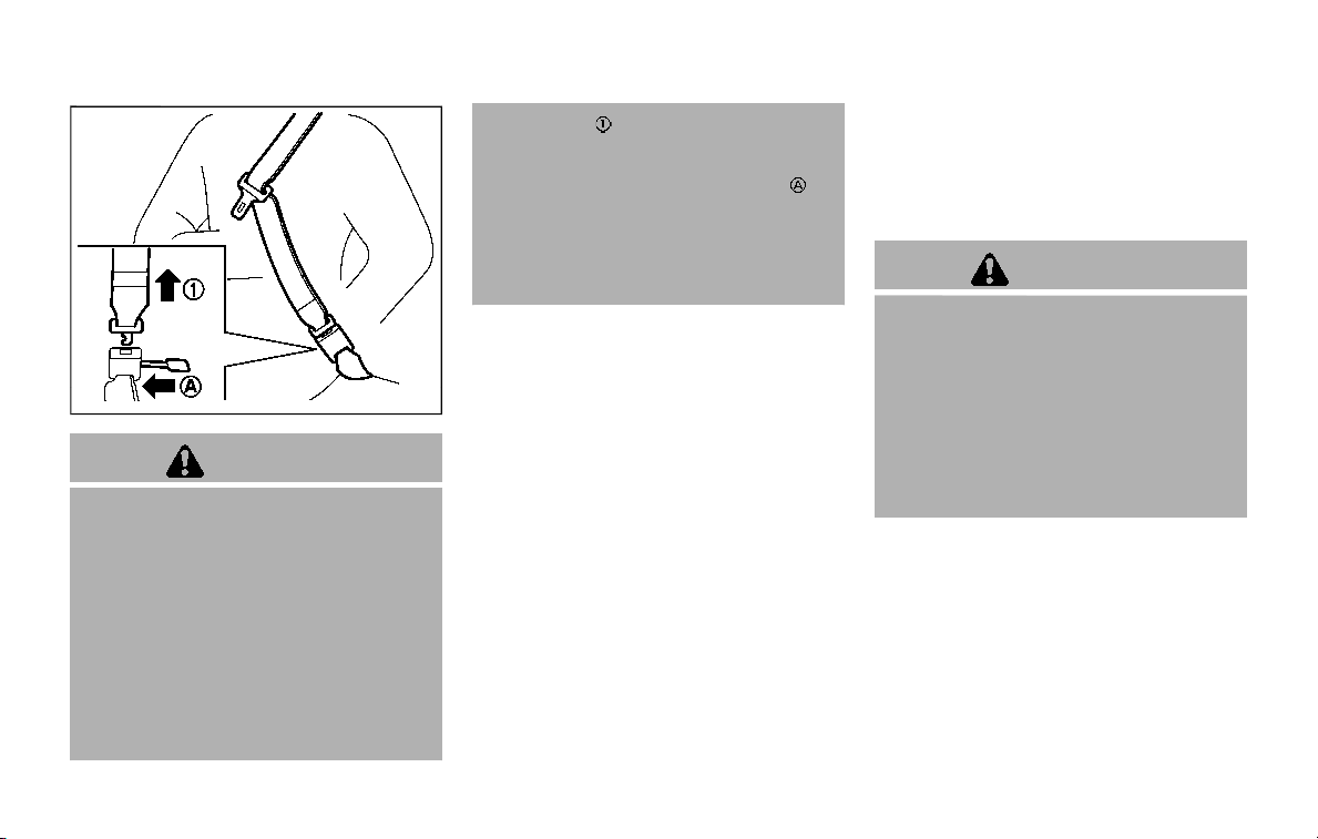
Attaching 3rd row center seat belt:
Always be sure the 3rd center seat belt
connector tongue and connector buckle
are attached. Disconnect only when fold-
ing down the 3rd row seat.
To connect the buckle:
1. Pull out the connector tongue from
the retractor base
.
2. Pull out the seat belt tongue from the
tongue holder
.
3. Pull the seat belt and fasten the
connector buckle until it clicks
.
The center seat belt connector tongue
and buckle are identified by the
and
mark.
The center seat belt connector tongue
can be attached only into the 3rd center
seat belt connector buckle.
To fasten the seat belt, see “Fastening the
seat belts” (P.1-23).
WARNING
. When attaching the 3rd center
seat belt connector, be certain
that the seatbacks are comple-
tely secured in the latched posi-
tion and the 3rd center seat belt
connector is completely secured.
Safety — seats, seat belts and supplemental restraint system 1-27

1-28 Safety — seats, seat belts and supplemental restraint system
. If the 3rd center seat belt con-
nector and the seatbacks are not
secured in the correct position,
serious personal injury may result
in an accident or sudden stop.
SSS1097
Storing 3rd row seat belt buckles
Before folding down the seat, put the
buckles in the storage of the seat cushion
to avoid dropping it under the seat
cushion.
SSS0896
Shoulder belt height adjustment
(for front seats and 2nd row seats)
The shoulder belt anchor height should
be adjusted to the position best for you.
(See “Precautions on seat belt usage” (P.1-
20).)
To adjust, push the button
, and then
move the shoulder belt anchor to the
desired position, so that the belt passes
over the center of the shoulder. The belt
should be away from your face and neck,
but not falling off of your shoulder.
Release the adjustment button to lock
the shoulder belt anchor into position.

WARNING
. After adjustment, release the ad-
justment button and try to move
the shoulder belt anchor up and
down to make sure it is securely
fixed in position.
. The shoulder belt anchor height
should be adjusted to the posi-
tion best for you. Failure to do so
may reduce the effectiveness of
the entire restraint system and
increase the chance or severity of
injury in an accident.
SEAT BELT EXTENDERS
If, because of body size or driving position,
it is not possible to properly fit the lap-
shoulder belt and fasten it, an extender
that is compatible with the installed seat
belts is available that can be purchased.
The extender adds approximately 8 in
(200 mm) of length and may be used for
either the driver or front passenger seat-
ing position. It is recommended you visit a
NISSAN dealer for assistance with pur-
chasing an extender if an extender is
required.
WARNING
. It is recommended that only
NISSAN seat belt extenders, made
by the same company which
made the original equipment seat
belts, be used with the NISSAN
seat belts.
. Adults and children who can use
the standard seat belt should not
use an extender. Such unneces-
sary use could result in serious
personal injury in the event of an
accident.
. Never use seat belt extenders to
install child restraints. If the child
restraint is not secured properly,
the child could be seriously in-
jured or killed in a collision or a
sudden stop.
SEAT BELT MAINTENANCE
. To clean the seat belt webbing, apply
a mild soap solution or any solution
recommended for cleaning upholstery
or carpets. Then, wipe with a cloth and
allow the seat belts to dry in the
shade. Do not allow the seat belts to
retract until they are completely dry.
. If dirt builds up in the shoulder belt
guide of the seat belt anchors, the
seat belts may retract slowly. Wipe the
shoulder belt guide with a clean, dry
cloth.
. Periodically check to see that the
seat belt and the metal components
such as buckles, tongues, retractors,
flexible wires and anchors work prop-
erly. If loose parts, deterioration, cuts
or other damage on the webbing is
found, the entire seat belt assembly
should be replaced.
Safety — seats, seat belts and supplemental restraint system 1-29
1-30 Safety — seats, seat belts and supplemental restraint system
JVR0183X
WARNING
Do not allow children to play with the
seat belts. Most seating positions are
equipped with Automatic Locking
Retractor (ALR) mode seat belts. If
the seat belt becomes wrapped
around a child’s neck with the ALR
mode activated, the child can be
seriously injured or killed if the seat
belt retracts and becomes tight. This
can occur even if the vehicle is
parked. Unbuckle the seat belt to
release the child. For the center of
the 3rd row bench seat, the connec-
tor tongue
may also be released.
Release the connector tongue by
inserting a suitable tool (such as a
key) into the connector buckle
.If
the seat belt cannot be unbuckled or
is already unbuckled, release the
child by cutting the seat belt with a
suitable tool (such as a knife or
scissors) to release the seat belt.
Children need adults to help protect
them.
They need to be properly restrained.
In addition to the general information in
this manual, child safety information is
available from many other sources, in-
cluding doctors, teachers, government
traffic safety offices, and community or-
ganizations. Every child is different, so be
sure to learn the best way to transport
your child.
There are three basic types of child
restraint systems:
. Rear-facing child restraint
. Forward-facing child restraint
. Booster seat
The proper restraint depends on the
child’s size. Generally, infants up to about
1 year and less than 20 lbs (9 kg) should
be placed in rear-facing child restraints.
Forward-facing child restraints are avail-
able for children who outgrow rear-facing
child restraints and are at least 1 year old.
Booster seats are used to help position a
vehicle lap/shoulder belt on a child who
can no longer use a forward-facing child
restraint.
WARNING
Infants and children need special
protection. The vehicle’s seat belts
may not fit them properly. The
shoulder belt may come too close
to the face or neck. The lap belt may
not fit over their small hip bones. In
an accident, an improperly fitting
seat belt could cause serious or fatal
injury. Always use appropriate child
restraints.
All U.S. states and Canadian provinces or
territories require the use of approved
child restraints for infants and small
children. See “Child restraints” (P.1-32).
A child restraint may be secured in the
vehicle by using either the LATCH (Lower
Anchor and Tethers for CHildren) system
or with the vehicle seat belt. See “Child
restraints” (P.1-32) for more information.
NISSAN recommends that all pre-teens
and children be restrained in the rear
CHILD SAFETY

seat. Studies show that children are
safer when properly restrained in the
rear seat than in the front seat.
This is especially important because
your vehicle has a supplemental re-
straint system (Air bag system) for the
front passenger. See “Supplemental re-
straint system” (P.1-54).
INFANTS
Infants up to at least 1 year old should be
placed in a rear-facing child restraint.
NISSAN recommends that infants be
placed in child restraints that comply with
Federal Motor Vehicle Safety Standards
or Canadian Motor Vehicle Safety Stan-
dards. You should choose a child restraint
that fits your vehicle and always follow
the manufacturer’s instructions for instal-
lation and use.
SMALL CHILDREN
Children that are over 1 year old and
weigh at least 20 lbs (9 kg) should remain
in a rear-facing child restraint as long as
possible up to the height or weight limit
of the child restraint. Children who out-
grow the height or weight limit of the
rear-facing child restraint and are at least
1 year old should be secured in a forward-
facing child restraint with a harness. Refer
to the manufacturer’s instructions for
minimum and maximum weight and
height recommendations. NISSAN recom-
mends that small children be placed in
child restraints that comply with Federal
Motor Vehicle Safety Standards or Cana-
dian Motor Vehicle Safety Standards. You
should choose a child restraint that fits
your vehicle and always follow the man-
ufacturer’s instructions for installation
and use.
LARGER CHILDREN
Children should remain in a forward-
facing child restraint with a harness until
they reach the maximum height or
weight limit allowed by the child restraint
manufacturer.
Once a child outgrows the height or
weight limit of the harness-equipped
forward-facing child restraint, NISSAN
recommends that the child be placed in
a commercially available booster seat to
obtain proper seat belt fit. For a seat belt
to fit properly, the booster seat should
raise the child so that the shoulder belt is
properly positioned across the chest and
the top, middle portion of the shoulder.
The shoulder belt should not cross the
neck or face and should not fall off the
shoulder. The lap belt should lie snugly
across the lower hips or upper thighs, not
the abdomen.
A booster seat can only be used in
seating positions that have a three-point
type seat belt. The booster seat should fit
the vehicle seat and have a label certify-
ing that it complies with Federal Motor
Vehicle Safety Standards or Canadian
Motor Vehicle Safety Standards.
A booster seat should be used until the
child can pass the seat belt fit test below:
. Are the child’s back and hips against
the vehicle seatback?
. Is the child able to sit without slouch-
ing?
. Do the child’s knees bend easily over
the front edge of the seat with feet flat
on the floor?
. Can the child safely wear the seat belt
(lap belt low and snug across the hips
and shoulder belt across mid-chest
and shoulder)?
. Is the child able to use the properly
adjusted head restraint/headrest?
. Will the child be able to stay in position
for the entire ride?
Safety — seats, seat belts and supplemental restraint system 1-31
1-32 Safety — seats, seat belts and supplemental restraint system
JVR0473X
If you answered no to any of these
questions, the child should remain in a
booster seat using a three-point type
seat belt.
NOTE:
Laws in some communities may follow
different guidelines. Check local and
state regulations to confirm your child
is using the correct restraint system
before traveling.
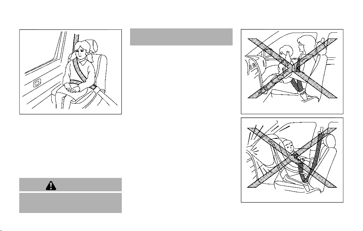
WARNING
Never let a child stand or kneel on
any seat and do not allow a child in
the cargo area. The child could be
seriously injured or killed in a sudden
stop or collision.
SSS0099
SSS0100
CHILD RESTRAINTS

PRECAUTIONS ON CHILD RE-
STRAINTS
WARNING
. Failure to follow the warnings
and instructions for proper use
and installation of child restraints
could result in serious injury or
death of a child or other passen-
gers in a sudden stop or collision:
— The child restraint must be
used and installed properly.
Always follow all of the child
restraint manufacturer’s in-
structions for installation and
use.
— Infants and children should
never be held on anyone’s
lap. Even the strongest adult
cannot resist the forces of a
collision.
— Do not put a seat belt around
both a child and another pas-
senger.
— NISSAN recommends that all
child restraints be installed in
the rear seat. Studies show
that children are safer when
properly restrained in the rear
seat than in the front seat. If
you must install a forward-
facing child restraint in the
front seat, see “Forward-fa-
cing child restraint installation
using the seat belts” (P.1-46).
— Even with the NISSAN Ad-
vanced Air Bag System, never
install a rear-facing child re-
straint in the front seat. An
inflating air bag could ser-
iously injure or kill a child. A
rear-facing child restraint
must only be used in the rear
seat.
— Be sure to purchase a child
restraint that will fit the child
and vehicle. Some child re-
straints may not fit properly
in your vehicle.
— Child restraint anchor points
are designed to withstand
loads from child restraints
that are properly fitted.
— Never use the anchor points
for adult seat belts or har-
nesses.
— A child restraint with a top
tether strap should not be
used in the front passenger
seat.
— Keep seatbacks as upright as
possible after fitting the child
restraint.
— Infants and children should
always be placed in an appro-
priate child restraint while in
the vehicle.
. When the child restraint is not in
use, keep it secured with the
LATCH system or a seat belt. In a
sudden stop or collision, loose
objects can injure occupants or
damage the vehicle.
CAUTION
A child restraint in a closed vehicle
can become very hot. Check the
seating surface and buckles before
placing a child in the child restraint.
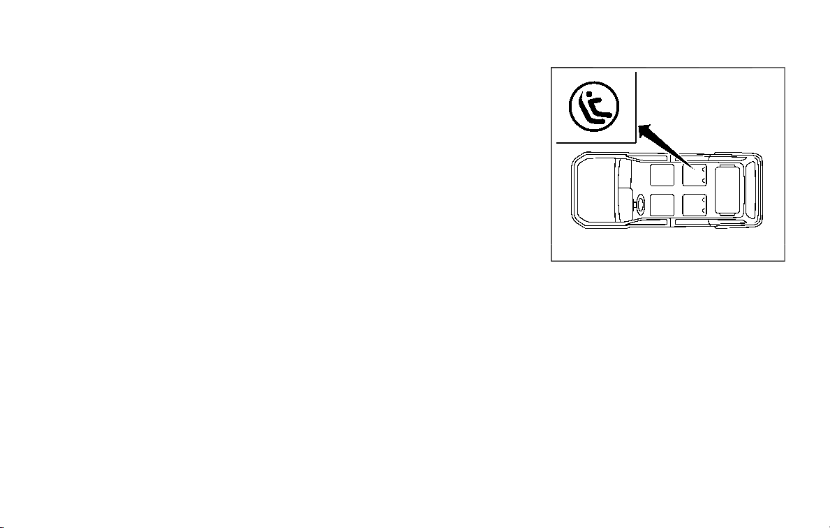
This vehicle is equipped with a universal
child restraint anchor system, referred to
as the LATCH (Lower Anchors and
Tethers for CHildren) system. Some child
restraints include rigid or webbing-
mounted attachments that can be con-
nected to these anchors.
Safety — seats, seat belts and supplemental restraint system 1-33
1-34 Safety — seats, seat belts and supplemental restraint system
For details, see “Lower Anchors and
Tethers for CHildren (LATCH) system ”
(P.1-35).
If you do not have a LATCH compatible
child restraint, the vehicle seat belts can
be used.
Several manufacturers offer child re-
straints for infants and small children of
various sizes. When selecting any child
restraint, keep the following points in
mind:
. Choose only a restraint with a label
certifying that it complies with Federal
Motor Vehicle Safety Standard 213 or
Canadian Motor Vehicle Safety Stan-
dard 213.
. Check the child restraint in your
vehicle to be sure it is compatible with
the vehicle’s seat and seat belt sys-
tem.
. If the child restraint is compatible with
your vehicle, place your child in the
child restraint and check the various
adjustments to be sure the child
restraint is compatible with your child.
Choose a child restraint that is de-
signed for your child’s height and
weight. Always follow all recom-
mended procedures.
. If the combined weight of the child
and child restraint is less than 65 lbs
(29.5 kg), you may use either the
LATCH lower anchors or the seat belt
to install the child restraint (not both
at the same time).
. If the combined weight of the child
and child restraint is greater than 65
lbs (29.5 kg), use the vehicle’s seat belt
(not the lower anchors) to install the
child restraint.
. Be sure to follow the child restraint
manufacturer’s instructions for instal-
lation.
All U.S. states and Canadian provinces
or territories require that infants and
small children be restrained in an ap-
proved child restraint at all times while
the vehicle is being operated. Canadian
law requires the top tether strap on
forward-facing child restraints be se-
cured to the designated anchor point
on the vehicle.
SSS1113
LATCH system lower anchor locations - captain’s
seats
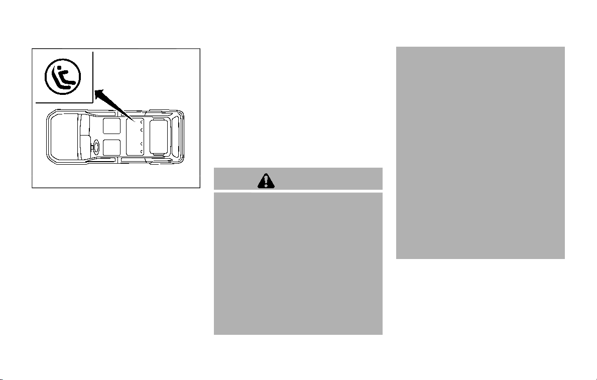
SSS1114
LATCH system lower anchor locations - bench seat
Lower Anchors and Tethers for
CHildren (LATCH) SYSTEM
Your vehicle is equipped with special
anchor points that are used with the
LATCH (Lower Anchors and Tethers for
CHildren) system compatible child re-
straints. This system may also be referred
to as the ISOFIX or ISOFIX compatible
system. With this system, you do not have
to use a vehicle seat belt to secure the
child restraint unless the combined
weight of the child and child restraint
exceeds 65 lbs (29.5 kg). If the combined
weight of the child and child restraint is
greater than 65 lbs (29.5 kg), use the
vehicle’s seat belt (not the lower anchors)
to install the child restraint. Be sure to
follow the child restraint manufacturer’s
instructions for installation.
The LATCH lower anchor points are
provided to install child restraints in the
following positions only:
. 2nd row captain’s seats (if so
equipped)
. 2nd row bench seat outboard posi-
tions only (if so equipped)
LATCH lower anchor
WARNING
Failure to follow the warnings and
instructions for proper use and in-
stallation of child restraints could
result in serious injury or death of a
child or other passengers in a sud-
den stop or collision:
. Attach LATCH system compatible
child restraints only at the loca-
tions shown in the illustration.
. Do not secure a child restraint in
the center rear seating position
using the LATCH lower anchors.
The child restraint will not be
secured properly.
. Inspect the lower anchors by in-
serting your fingers into the low-
er anchor area. Feel to make sure
there are no obstructions over
the anchors such as seat belt
webbing or seat cushion material.
The child restraint will not be
secured properly if the lower
anchors are obstructed.
Child restraint anchorages are de-
signed to withstand only those loads
imposed by correctly fitted child
restraints. Under no circumstances
are they to be used to attach adult
seat belts, or other items or equip-
ment to the vehicle. Doing so could
damage the child restraint an-
chorages. The child restraint will not
be properly installed using the da-
maged anchorage, and a child could
be seriously injured or killed in a
collision.
LATCH lower anchor location
The LATCH lower anchor points are
provided to install child restraints in the
rear outboard seating positions only. Do
not attempt to install a child restraint in
the center seating position using the
LATCH lower anchors.
Safety — seats, seat belts and supplemental restraint system 1-35
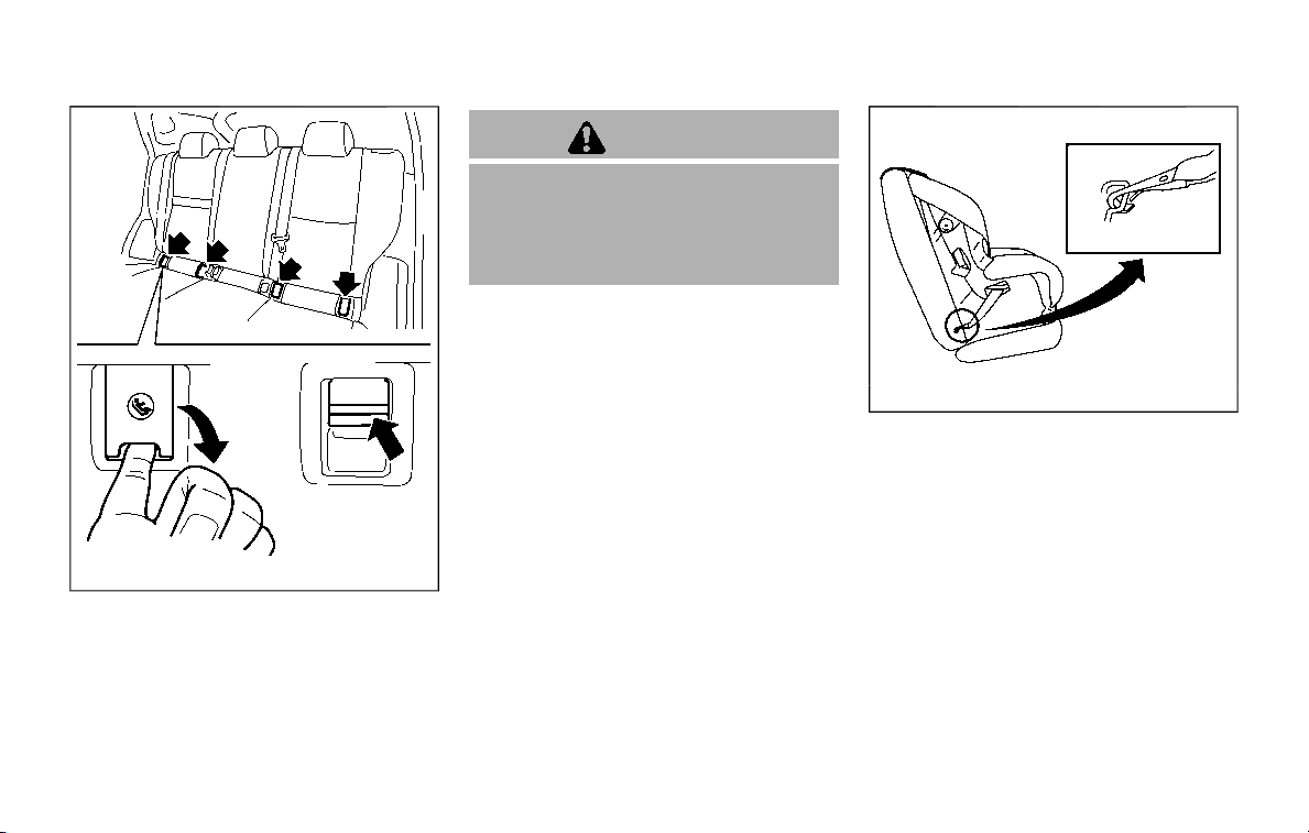
1-36 Safety — seats, seat belts and supplemental restraint system
JVR0631X
LATCH lower anchor cover removal
The LATCH lower anchor points are
located under the covers labelled ISOFIX
at the bottom of the rear outboard seat
cushions. To access a LATCH lower an-
chor point, insert your finger into the
cover and pull the cover off.
CAUTION
Store the loose LATCH covers (for
example, in the console box) where
they will not get damaged to avoid
losing them. (See “Console box” (P.2-
56).)
SSS0643
LATCH webbing-mounted attachment
Installing child restraint LATCH
lower anchor attachments
LATCH compatible child restraints include
two rigid or webbing-mounted attach-
ments that can be connected to two
anchors located at certain seating posi-
tions in your vehicle. With this system, you
do not have to use a vehicle seat belt to
secure the child restraint. Check your
child restraint for a label stating that it is
compatible with LATCH. This information
may also be in the instructions provided
by the child restraint manufacturer.
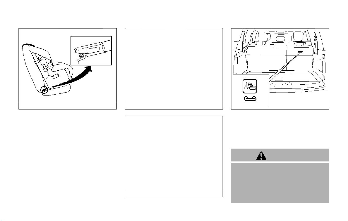
SSS0644
LATCH rigid-mounted attachment
When installing a child restraint, carefully
read and follow the instructions in this
manual and those supplied with the child
restraint.
JVR0619X
2nd row captain’s seat
JVR0620X
2nd row bench seat
JVR0621X
3rd row bench seat
TOP TETHER STRAP CHILD RE-
STRAINT
If the manufacturer of your child restraint
requires the use of a top tether strap, it
must be secured to an anchor point.
WARNING
. In the 3rd row bench seat, a child
restraint with a top tether strap
can only be used in the outboard
seating position (right side). Do
not place it in the outboard seat-
ing position (left side) and center
position and attempt to angle the
Safety — seats, seat belts and supplemental restraint system 1-37

1-38 Safety — seats, seat belts and supplemental restraint system
tether strap to the outboard seat-
ing position (right side).
. Child restraint anchorages are
designed to withstand only those
loads imposed by correctly fitted
child restraints. Under no circum-
stances are they to be used to
attach adult seat belts, or other
items or equipment to the vehi-
cle. Doing so could damage the
child restraint anchorages. The
child restraint will not be properly
installed using the damaged an-
chorage, and a child could be
seriously injured or killed in a
collision.
. Properly secure cargo and do not
allow it to contact the top tether
strap when it is attached to the
top tether anchor. Cargo that is
not properly secured or cargo
that contacts the top tether strap
may damage the top tether strap
during a collision. Your child
could be seriously injured or
killed in a collision if the child
restraint top tether strap is da-
maged.
Top tether anchor point locations
Anchor points are located in the following
locations:
. 2nd row bench seat (if so equipped)
on the seatback of the outboard
seating positions as shown.
. 2nd row captain’s seats (if so
equipped) on the seatback of the
outboard seating positions as shown.
. 3rd row bench seat on the seatback of
the outboard seating position (right
side) as shown.
If you have any questions when instal-
ling a top tether strap child restraint on
the rear seat, it is recommended you
visit a NISSAN dealer for this service.
REAR-FACING CHILD RESTRAINT
INSTALLATION USING LATCH
Refer to all Warnings and Cautions in the
“Child safety” and “Child restraints” sec-
tions before installing a child restraint.
Do not use the lower anchors if the
combined weight of the child and the
child restraint exceeds 65 lbs (29.5 kg). If
the combined weight of the child and the
child restraint is greater than 65 lbs (29.5
kg), use the vehicle’s seat belt (not the
lower anchors) to install the child re-
straint. Be sure to follow the child re-
straint manufacturer’s instructions for
installation.
Follow these steps to install a rear-facing
child restraint in the 2nd row seats using
the LATCH system:
1. Position the child restraint on the seat.
Always follow the child restraint man-
ufacturer’s instructions.
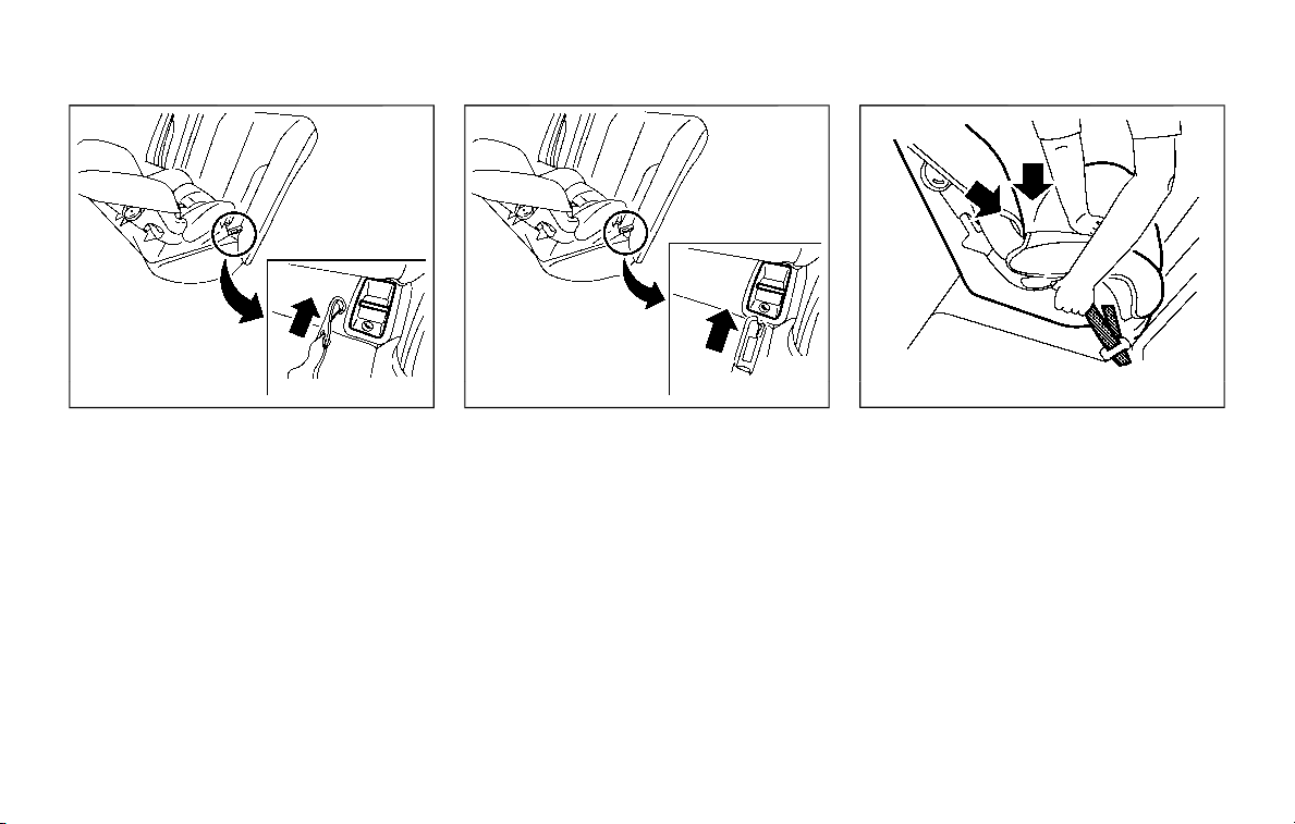
JVR0635X
Rear-facing web-mounted — step 2
2. Secure the child restraint anchor at-
tachments to the LATCH lower an-
chors. Check to make sure the LATCH
attachment is properly attached to
the lower anchors.
JVR0636X
Rear-facing rigid-mounted — step 2
SSS0639
Rear-facing — step 3
3. For child restraints that are equipped
with webbing-mounted attachments,
remove any additional slack from the
anchor attachments. Press downward
and rearward firmly in the center of
the child restraint with your hand to
compress the vehicle seat cushion
and seatback while tightening the
webbing of the anchor attachments.
Safety — seats, seat belts and supplemental restraint system 1-39
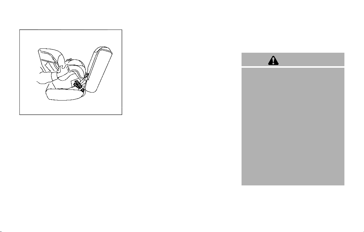
1-40 Safety — seats, seat belts and supplemental restraint system
SSS0650
Rear-facing — step 4
4. After attaching the child restraint, test
it before you place the child in it. Push
it from side to side while holding the
child restraint near the LATCH attach-
ment path. The child restraint should
not move more than 1 inch (25 mm),
from side to side. Try to tug it forward
and check to see if the LATCH attach-
ment holds the restraint in place. If the
restraint is not secure, tighten the
LATCH attachment as necessary, or
put the restraint in another seat and
test it again. You may need to try a
different child restraint or try installing
by using the vehicle seat belt (if
applicable). Not all child restraints fit
in all types of vehicles.
5. Check to make sure the child restraint
is properly secured prior to each use. If
the child restraint is loose, repeat
steps 1 through 4.
REAR-FACING CHILD RESTRAINT
INSTALLATION USING THE SEAT
BELTS
WARNING
. The three-point seat belt with
Automatic Locking Retractor
(ALR) must be used when instal-
ling a child restraint. Failure to
use the ALR mode will result in
the child restraint not being prop-
erly secured. The restraint could
tip over or be loose and cause
injury to a child in a sudden stop
or collision. Also, it can change
the operation of the front pas-
senger air bag. See “Front pas-
senger air bag and status light”
(P.1-62).
. When installing a child restraint
system in the 3rd center seat
position, both the center seat belt
connector tongue and buckle
tongue must be secured. See
“3rd row center seat belt” (P.1-26).
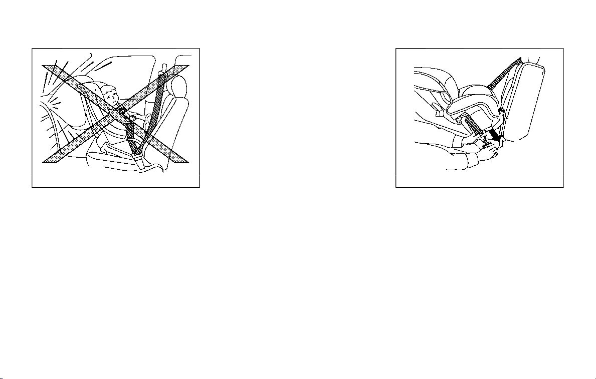
SSS0100
Rear-facing — step 1
Refer to all Warnings and Cautions in the
“Child safety” (P.1-30) and “Child restraints”
(P.1-32) before installing a child restraint.
Do not use the lower anchors if the
combined weight of the child and the
child restraint exceeds 65 lbs (29.5 kg). If
the combined weight of the child and the
child restraint is greater than 65 lbs (29.5
kg), use the vehicle’s seat belt (not the
lower anchors) to install the child re-
straint. Be sure to follow the child re-
straint manufacturer’s instructions for
installation.
Follow these steps to install a rear-facing
child restraint using the vehicle seat belts
in the rear seats:
1. Child restraints for infants must be
used in the rear-facing direction and
therefore must not be used in the
front seat. Position the child restraint
on the seat. Always follow the re-
straint manufacturer’s instructions.
SSS0654
Rear-facing — step 2
2. Route the seat belt tongue through
the child restraint and insert it into the
buckle until you hear and feel the
latch engage. Be sure to follow the
child restraint manufacturer’s instruc-
tions for belt routing.
Safety — seats, seat belts and supplemental restraint system 1-41
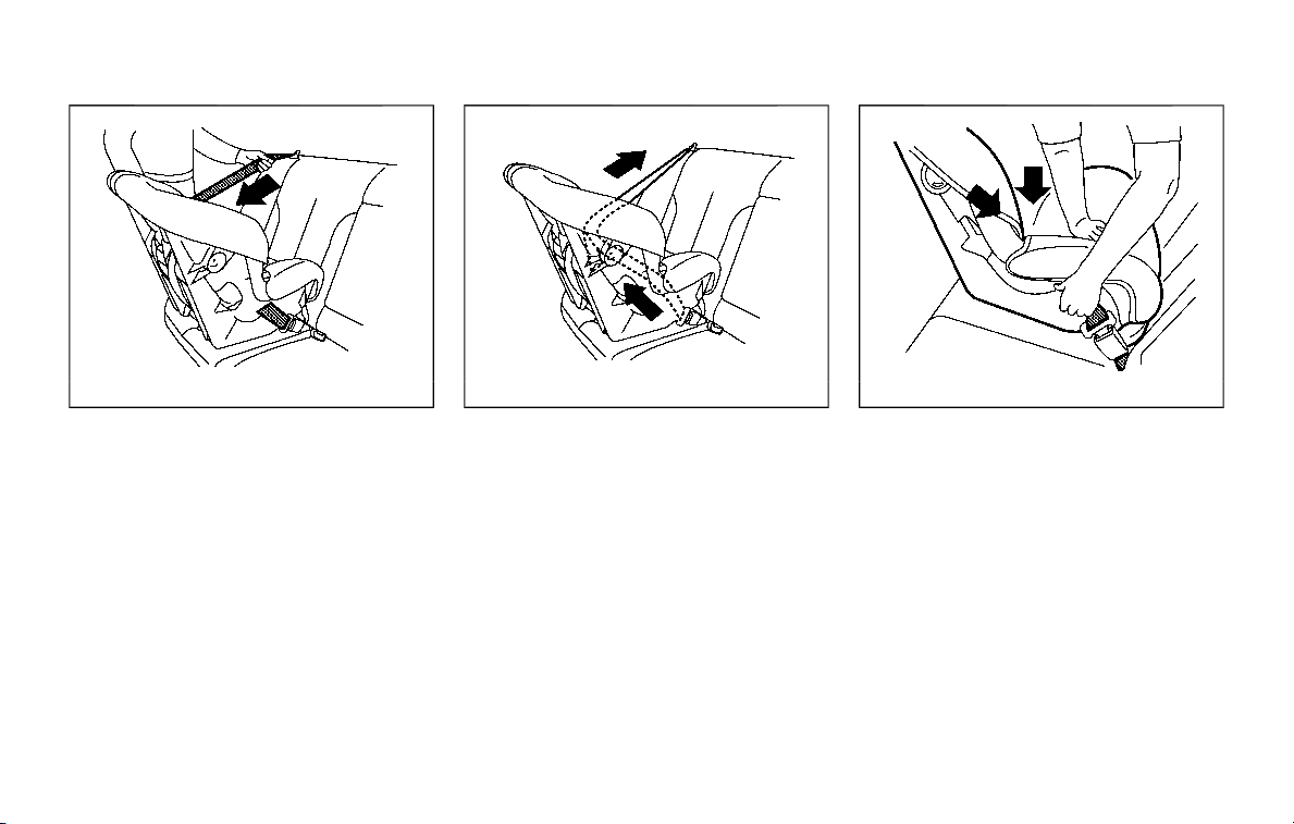
1-42 Safety — seats, seat belts and supplemental restraint system
SSS0655
Rear-facing — step 3
3. Pull the shoulder belt until the belt is
fully extended. At this time, the seat
belt retractor is in the Automatic
Locking Retractor (ALR) mode (child
restraint mode). It reverts to the
Emergency Locking Retractor (ELR)
mode when the seat belt is fully
retracted.
SSS0656
Rear-facing — step 4
4. Allow the seat belt to retract. Pull up
on the shoulder belt to remove any
slack in the belt.
SSS0657
Rear-facing — step 5
5. Remove any additional slack from the
seat belt; press downward and rear-
ward firmly in the center of the child
restraint to compress the vehicle seat
cushion and seatback while pulling up
on the seat belt.
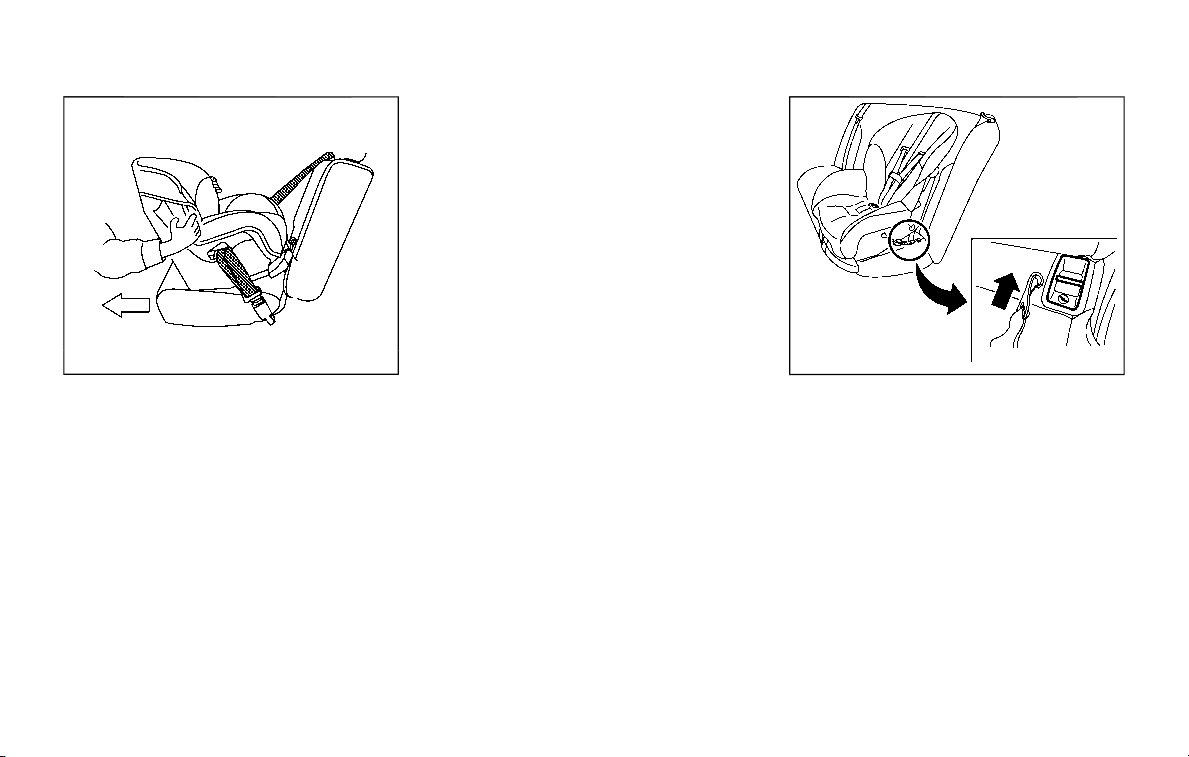
SSS0658
Rear-facing — step 6
6. After attaching the child restraint, test
it before you place the child in it. Push
it from side to side while holding the
child restraint near the seat belt path.
The child restraint should not move
more than 1 inch (25 mm), from side to
side. Try to tug it forward and check to
see if the belt holds the restraint in
place. If the restraint is not secure,
tighten the seat belt as necessary, or
put the restraint in another seat and
test it again. You may need to try a
different child restraint. Not all child
restraints fit in all types of vehicles.
7. Check to make sure that the child
restraint is properly secured prior to
each use. If the seat belt is not locked,
repeat steps 1 through 6.
After the child restraint is removed and
the seat belt fully retracted, the ALR mode
(child restraint mode) is canceled.
FORWARD-FACING CHILD RE-
STRAINT INSTALLATION USING
LATCH
Refer to all Warnings and Cautions in the
“Child safety” and “Child restraints” sec-
tions before installing a child restraint.
Do not use the lower anchors if the
combined weight of the child and the
child restraint exceeds 65 lbs (29.5 kg). If
the combined weight of the child and the
child restraint is greater than 65 lbs (29.5
kg), use the vehicle’s seat belt (not the
lower anchors) to install the child re-
straint. Be sure to follow the child re-
straint manufacturer’s instructions for
installation.
Follow these steps to install a forward-
facing child restraint using the LATCH
system:
1. Position the child restraint on the seat.
Always follow the child restraint man-
ufacturer’s instructions.
JVR0637X
Forward-facing web-mounted — step 2
2. Secure the child restraint anchor at-
tachments to the LATCH lower an-
chors. Check to make sure the LATCH
attachment is properly attached to
the lower anchors.
If the child restraint is equipped with a
top tether strap, route the top tether
strap and secure the tether strap to
the tether anchor point. See “Installing
top tether strap” (P.1-46). Do not install
child restraints that require the use of
a top tether strap in seating positions
that do not have a top tether anchor.
Safety — seats, seat belts and supplemental restraint system 1-43
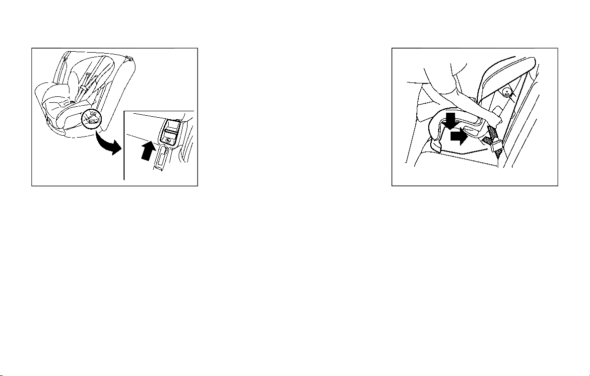
1-44 Safety — seats, seat belts and supplemental restraint system
JVR0638X
Forward-facing rigid-mounted — step 2
3. The back of the child restraint should
be secured against the vehicle seat-
back.
If necessary, adjust or remove the
head restraint to obtain the correct
child restraint fit. If the head restraint
is removed, store it in a secure place.
Be sure to reinstall the head re-
straint when the child restraint is
removed. See “Head restraints/head-
rests” (P.1-14) for head restraint adjust-
ment information.
If the seating position does not have
an adjustable head restraint or a
headrest and it is interfering with the
proper child restraint fit, try another
seating position or a different child
restraint.
SSS0647
Forward-facing — step 4
4. For child restraints that are equipped
with webbing-mounted attachments,
remove any additional slack from the
anchor attachments. Press downward
and rearward firmly in the center of
the child restraint with your knee to
compress the vehicle seat cushion
and seatback while tightening the
webbing of the anchor attachments.
5. Tighten the tether strap according to
the manufacturer’s instructions to
remove any slack.
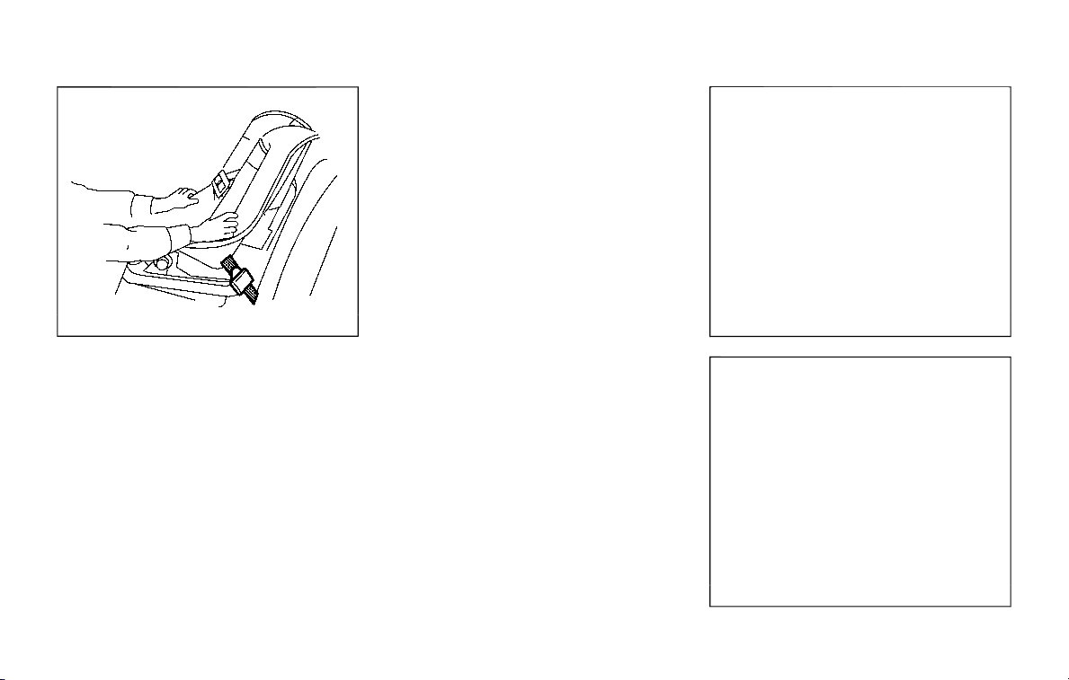
SSS0638
Forward-facing — step 6
6. After attaching the child restraint, test
it before you place the child in it. Push
it from side to side while holding the
child restraint near the LATCH attach-
ment path. The child restraint should
not move more than 1 inch (25 mm),
from side to side. Try to tug it forward
and check to see if the LATCH attach-
ment holds the restraint in place. If the
restraint is not secure, tighten the
LATCH attachment as necessary, or
put the restraint in another seat and
test it again. You may need to try a
different child restraint. Not all child
restraints fit in all types of vehicles.
7. Check to make sure the child restraint
is properly secured prior to each use. If
the child restraint is loose, repeat
steps 1 through 6.
JVR0619X
2nd row captain’s seat
JVR0620X
2nd row bench seat
Safety — seats, seat belts and supplemental restraint system 1-45
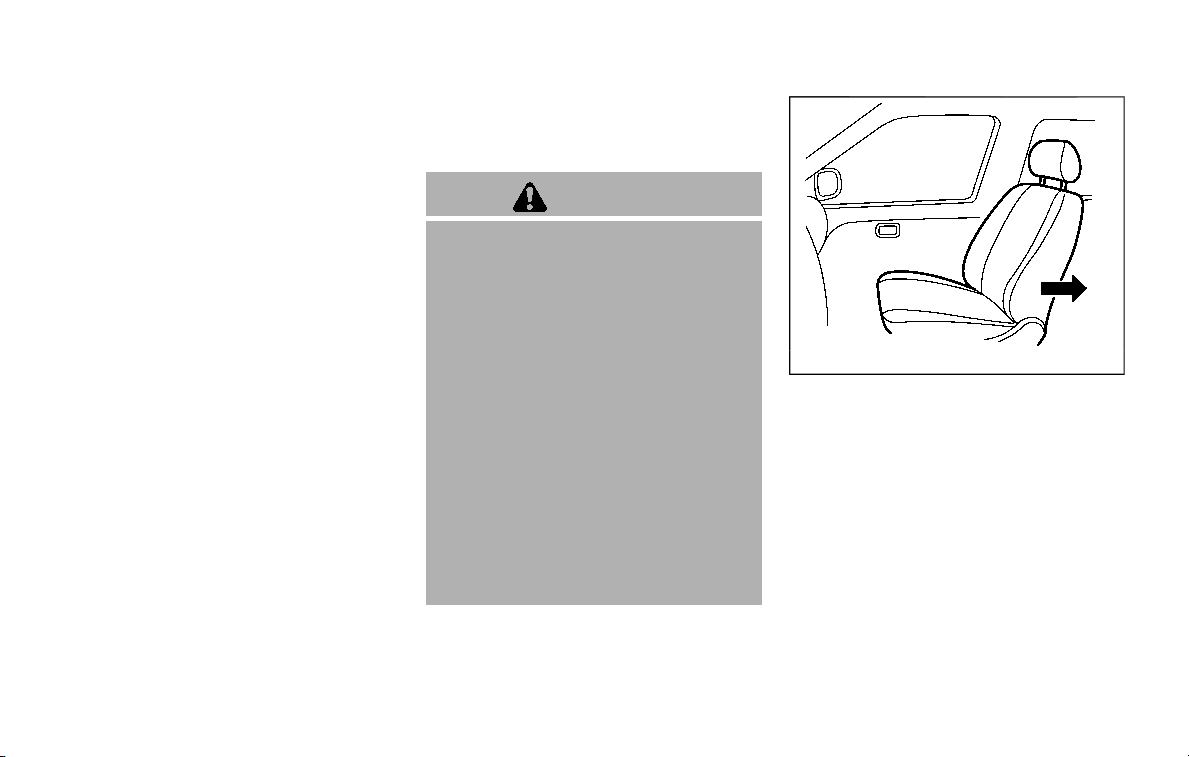
1-46 Safety — seats, seat belts and supplemental restraint system
Installing top tether strap
First, secure the child restraint with the
LATCH lower anchors (2nd row captain’s
or bench outboard seating positions
only).
1. If necessary, raise or remove the head
restraint or headrest to position the
top tether strap over the top of the
seatback. If the head restraint or
headrest is removed, store it in a
secure place. Be sure to reinstall the
head restraint or headrest when the
child restraint is removed. See “Head
restraints/headrests” (P.1-14) for head
restraint or headrest adjustment, re-
moval and installation information.
2. Secure the tether strap to the tether
anchor point on the back of each
seatback behind the child restraint.
3. Tighten the tether strap according to
the manufacturer’s instructions to
remove any slack. Make sure the head
restraint or headrest does not contact
the top tether strap.
If you have any questions when instal-
ling a top tether strap on the rear seat,
it is recommended you visit a NISSAN
dealer for this service.
FORWARD-FACING CHILD RE-
STRAINT INSTALLATION USING THE
SEAT BELTS
WARNING
. The three-point seat belt with
Automatic Locking Retractor
(ALR) must be used when instal-
ling a child restraint. Failure to
use the ALR mode will result in
the child restraint not being prop-
erly secured. The restraint could
tip over or be loose and cause
injury to a child in a sudden stop
or collision. Also, it can change
the operation of the front pas-
senger air bag. See “Front pas-
senger air bag and status light”
(P.1-62)
. When installing a child restraint
system in the 3rd center position,
both the center seat belt connec-
tor tongue and buckle tongue
must be secured. See “3rd row
center seat belt” (P.1-26).
SSS0640
Forward-facing (front passenger seat) — step 1
Refer to all Warnings and Cautions in the
“Child safety” and “Child restraints” sec-
tions before installing a child restraint.
Do not use the lower anchors if the
combined weight of the child and the
child restraint exceeds 65 lbs (29.5 kg). If
the combined weight of the child and the
child restraint is greater than 65 lbs (29.5
kg), use the vehicle’s seat belt (not the
lower anchors) to install the child re-
straint. Be sure to follow the child re-
straint manufacturer’s instructions for
installation.
Follow these steps to install a forward-
facing child restraint using the vehicle
seat belt in the rear seats or in the front
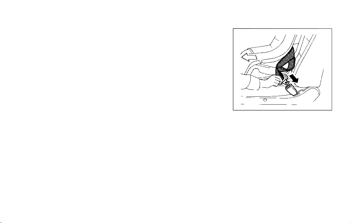
passenger seat:
1. If you must install a child restraint in
the front seat, it should be placed in
a forward-facing direction only.
Move the seat to the rearmost posi-
tion. Child restraints for infants must
be used in the rear-facing direction
and, therefore, must not be used in
the front seat.
2. Position the child restraint on the seat.
Always follow the child restraint man-
ufacturer’s instructions.
The back of the child restraint should
be secured against the vehicle seat-
back.
If necessary, adjust or remove the
head restraint or headrest to obtain
the correct child restraint fit. If the
head restraint or headrest is removed,
store it in a secure place. Be sure to
reinstall the head restraint or head-
rest when the child restraint is re-
moved. See “Head restraints/
headrests” (P.1-14) for head restraint
or headrest adjustment, removal and
installation information.
If the seating position does not have
an adjustable head restraint or a
headrest and it is interfering with the
proper child restraint fit, try another
seating position or a different child
restraint.
SSS0360B
Forward-facing — step 3
3. Route the seat belt tongue through
the child restraint and insert it into the
buckle until you hear and feel the
latch engage. Be sure to follow the
child restraint manufacturer’s instruc-
tions for belt routing.
If the child restraint is equipped with a
top tether strap, route the top tether
strap and secure the tether strap to
the tether anchor point (rear seat
installation only). See “Installing top
tether strap” (P.1-50). Do not install
child restraints that require the use of
a top tether strap in seating positions
that do not have a top tether anchor.
Safety — seats, seat belts and supplemental restraint system 1-47
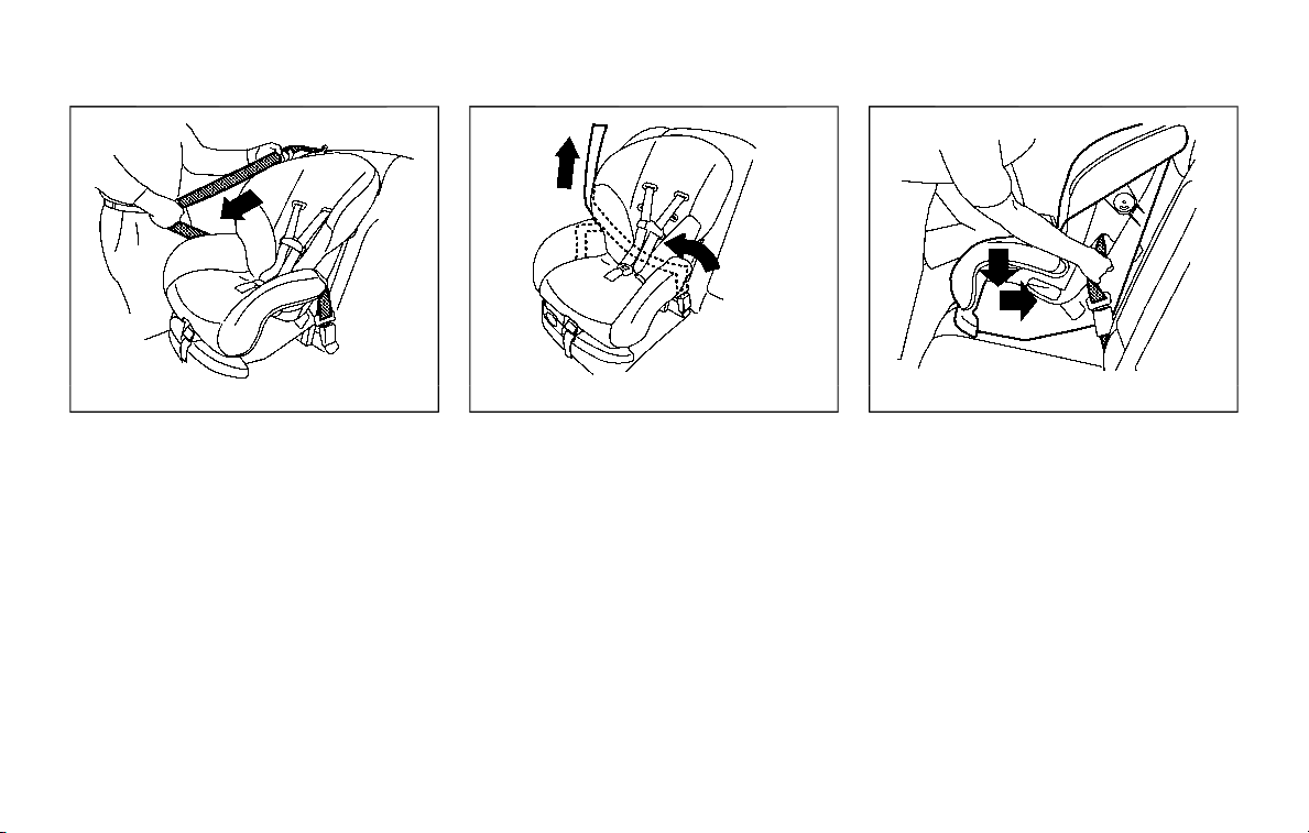
1-48 Safety — seats, seat belts and supplemental restraint system
SSS0651
Forward-facing — step 4
4. Pull the shoulder belt until the belt is
fully extended. At this time, the seat
belt retractor is in the Automatic
Locking Retractor (ALR) mode (child
restraint mode). It reverts to Emer-
gency Locking Retractor (ELR) mode
when the seat belt is fully retracted.
SSS0652
Forward-facing — step 5
5. Allow the seat belt to retract. Pull up
on the shoulder belt to remove any
slack in the belt.
SSS0653
Forward-facing — step 6
6. Remove any additional slack from the
seat belt; press downward and rear-
ward firmly in the center of the child
restraint with your knee to compress
the vehicle seat cushion and seatback
while pulling up on the seat belt.
7. Tighten the tether strap according to
the manufacturer’s instructions to
remove any slack.
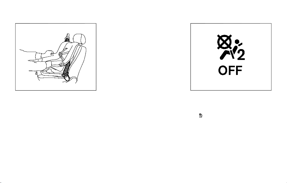
SSS0641
Forward-facing — step 8
8. After attaching the child restraint, test
it before you place the child in it. Push
it from side to side while holding the
child restraint near the seat belt path.
The child restraint should not move
more than 1 inch (25 mm), from side to
side. Try to tug it forward and check to
see if the belt holds the restraint in
place. If the restraint is not secure,
tighten the seat belt as necessary, or
put the restraint in another seat and
test it again. You may need to try a
different child restraint. Not all child
restraints fit in all types of vehicles.
9. Check to make sure the child restraint
is properly secured prior to each use. If
the seat belt is not locked, repeat
steps 2 through 8.
SSS1099
Forward-facing — step 10
10. If the child restraint is installed in the
front passenger seat, place the igni-
tion switch in the ON position. The
front passenger air bag status light
should illuminate. If this light is not
illuminated, see “Front passenger air
bag and status light” (P.1-62). Move
the child restraint to another seating
position. Have the system checked. It
is recommended you visit a NISSAN
dealer for this service.
After the child restraint is removed and
the seat belt is fully retracted, the ALR
mode (child restraint mode) is canceled.
Safety — seats, seat belts and supplemental restraint system 1-49
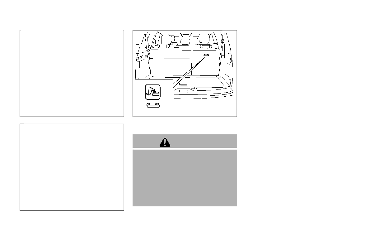
1-50 Safety — seats, seat belts and supplemental restraint system
JVR0619X
2nd row captain’s seat
JVR0620X
2nd row bench seat
JVR0621X
3rd row bench seat
Installing top tether strap
WARNING
In the 3rd row bench seat, a child
restraint with a top tether strap can
only be used in the outboard seating
position (right side). Do not place it in
the outboard seating position (left
side) and center position and at-
tempt to angle the tether strap to
the outboard seating position (right
side).
First, secure the child restraint with the
seat belt.
1. If necessary, raise or remove the head
restraint or headrest to position the
top tether strap over the top of the
seatback. If the head restraint or
headrest is removed, store it in a
secure place. Be sure to reinstall the
head restraint or headrest when the
child restraint is removed. See “Head
restraints/headrests” (P.1-14) for head
restraint or headrest adjustment, re-
moval and installation information.
2. Secure the tether strap to the tether
anchor point on the back of each
seatback (2nd row seat) or right side
seatback (3rd row seat) behind the
child restraint.
3. Tighten the tether strap according to
the manufacturer’s instructions to
remove any slack. Make sure the head
restraint or headrest does not contact
the top tether strap.
If you have any questions when instal-
ling a top tether strap on the rear seat,
it is recommended you visit a NISSAN
dealer for this service.
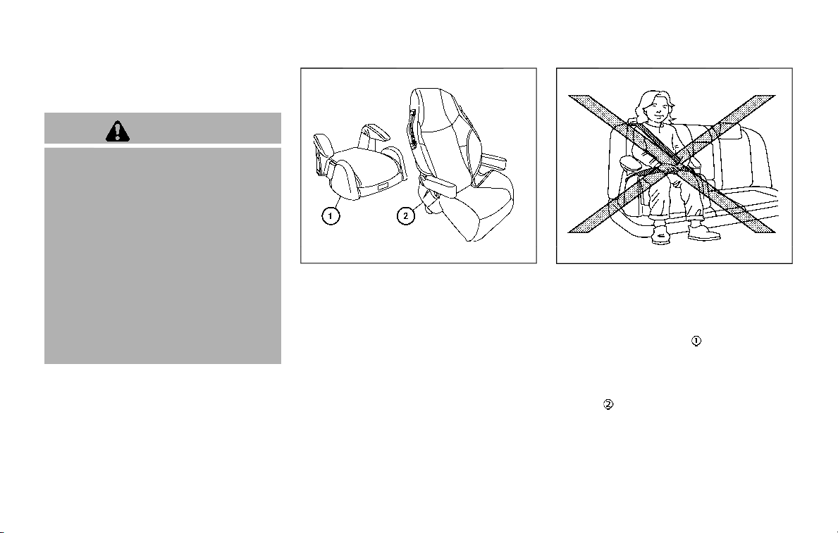
BOOSTER SEATS
Precautions on booster seats
WARNING
If a booster seat and seat belt are not
used properly, the risk of a child
being injured in a sudden stop or
collision greatly increases:
. Make sure the shoulder portion of
the belt is away from the child’s
face and neck and the lap portion
of the belt does not cross the
stomach.
. Make sure the shoulder belt is not
behind the child or under the
child’s arm.
. A booster seat must only be
installed in a seating position that
has a lap/shoulder belt.
LRS0455
Booster seats of various sizes are offered
by several manufacturers. When selecting
any booster seat, keep the following
points in mind:
. Choose only a booster seat with a
label certifying that it complies with
Federal Motor Vehicle Safety Standard
213 or Canadian Motor Vehicle Safety
Standard 213.
. Check the booster seat in your vehicle
to be sure it is compatible with the
vehicle’s seat and seat belt system.
LRS0453
. Make sure the child’s head will be
properly supported by the booster
seat or vehicle seat. The seatback
must be at or above the center of
the child’s ears. For example, if a low
back booster seat
is chosen, the
vehicle seatback must be at or above
the center of the child’s ears. If the
seatback is lower than the center of
the child’s ears, a high back booster
seat
should be used.
. If the booster seat is compatible with
your vehicle, place your child in the
booster seat and check the various
adjustments to be sure the booster
seat is compatible with your child.
Always follow all recommended pro-
Safety — seats, seat belts and supplemental restraint system 1-51
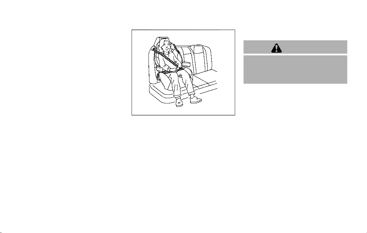
1-52 Safety — seats, seat belts and supplemental restraint system
cedures.
LRS0464
All U.S. states and Canadian provinces
or territories require that infants and
small children be restrained in an ap-
proved child restraint at all times while
the vehicle is being operated.
The instructions in this section apply to
booster seat installation in the rear seats
or the front passenger seat.
Booster seat installation
CAUTION
Do not use the lap/shoulder belt
Automatic Locking Retractor (ALR)
mode when using a booster seat
with the seat belts.
Refer to all Warnings and Cautions in the
“Child safety”, “Child restraints” and “Boos-
ter seats” sections earlier in this section
before installing a child restraint.
Follow these steps to install a booster
seat in the rear seat or in the front
passenger seat:
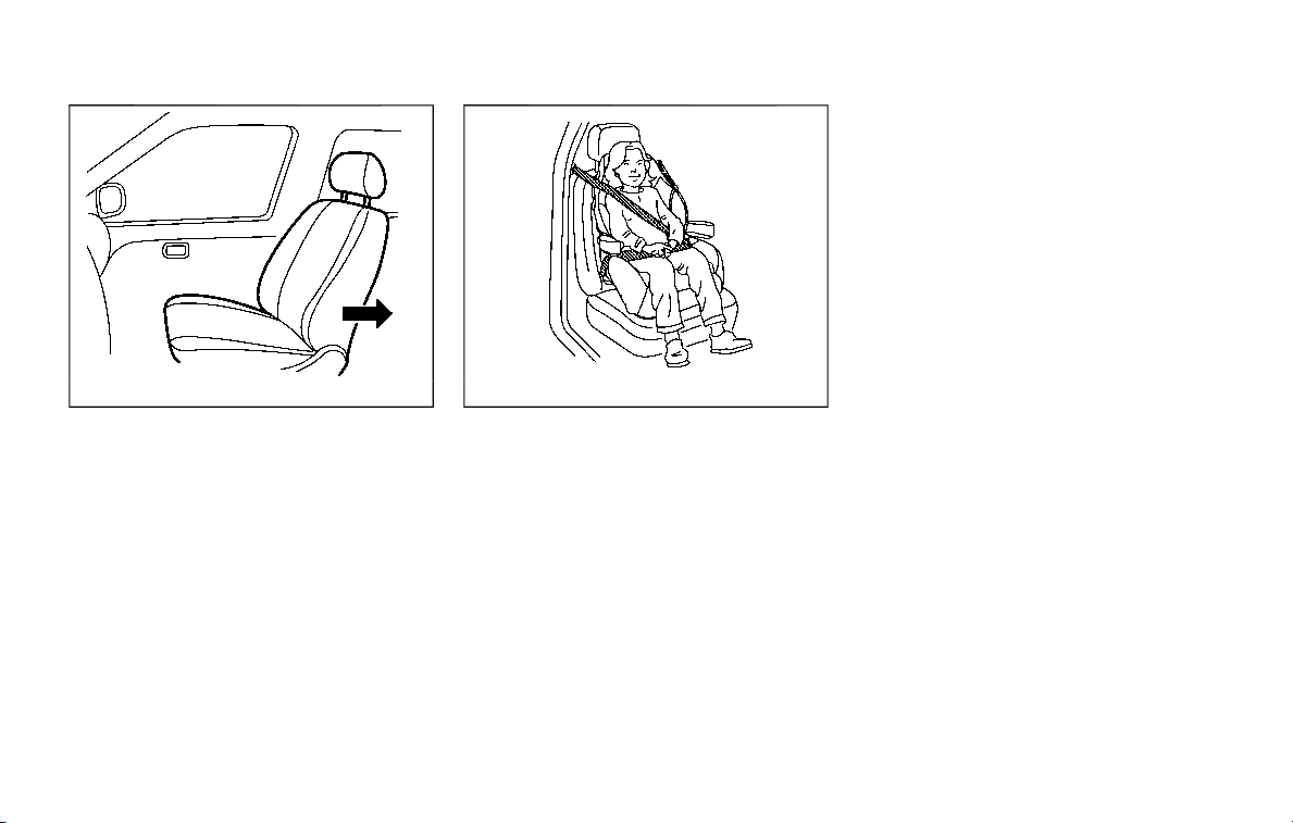
SSS0640
1. If you must install a booster seat in
the front seat, move the seat to the
rearmost position.
2. Position the booster seat on the seat.
Only place it in a forward-facing
direction. Always follow the booster
seat manufacturer’s instructions.
LRS0454
Front passenger position
3. The booster seat should be positioned
on the vehicle seat so that it is stable.
If necessary, adjust or remove the
head restraint or headrest to obtain
the correct booster seat fit. If the head
restraint or headrest is removed, store
it in a secure place. Be sure to
reinstall the head restraint or head-
rest when the booster seat is re-
moved. See “Head restraints/
headrests” (P.1-14) for head restraint
or headrest adjustment, removal and
installation information.
If the seating position does not have
an adjustable head restraint or a
headrest and it is interfering with the
proper booster seat fit, try another
seating position or a different booster
seat.
4. Position the lap portion of the seat
belt low and snug on the child’s hips.
Be sure to follow the booster seat
manufacturer’s instructions for ad-
justing the seat belt routing.
5. Pull the shoulder belt portion of the
seat belt toward the retractor to take
up extra slack. Be sure the shoulder
belt is positioned across the top,
middle portion of the child’s shoulder.
Be sure to follow the booster seat
manufacturer’s instructions for ad-
justing the seat belt routing.
6. Follow the warnings, cautions and
instructions for properly fastening a
seat belt shown in “Seat belts” (P.1-20).
Safety — seats, seat belts and supplemental restraint system 1-53
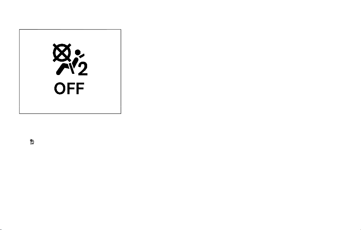
1-54 Safety — seats, seat belts and supplemental restraint system
SSS1099
7. If the booster seat is installed in the
front passenger seat, place the igni-
tion switch in the ON position. The
front passenger air bag status light
may or may not illuminate de-
pending on the size of the child and
the type of booster seat used. See
“Front passenger air bag and status
light” (P.1-62).
PRECAUTIONS ON SUPPLEMENTAL
RESTRAINT SYSTEM
This Supplemental Restraint System (SRS)
section contains important information
concerning the following systems.
. Driver and passenger supplemental
front-impact air bag (NISSAN Ad-
vanced Air Bag System)
. Front seat-mounted side-impact sup-
plemental air bag
. Roof-mounted curtain side-impact
and rollover supplemental air bag
. Seat belt with pretensioner
Supplemental front-impact air bag sys-
tem: The NISSAN Advanced Air Bag Sys-
tem can help cushion the impact force to
the head and chest of the driver and front
passenger in certain frontal collisions.
Front seat-mounted side-impact sup-
plemental air bag system: This system
can help cushion the impact force to the
chest and pelvis area of the driver and
front passenger in certain side impact
collisions. The supplemental side air bag
is designed to inflate on the side where
the vehicle is impacted.
Roof-mounted curtain side-impact and
rollover supplemental air bag system:
This system can help cushion the impact
force to the head of occupants in front
and rear (2nd and 3rd) outboard seating
positions in certain side impact or rollover
collisions. In a side impact, the curtain air
bags are designed to inflate on the side
where the vehicle is impacted. In a roll-
over, the curtain air bags on both sides
are designed to inflate. Under both side-
impact and rollover situations, the curtain
air bags will remain inflated for a short
period of time.
These supplemental restraint systems are
designed to supplement the crash pro-
tection provided by the driver and pas-
senger seat belts and are not a
substitute for them. Seat belts should
always be correctly worn and the occu-
pant seated a suitable distance away
from the steering wheel, instrument pa-
nel and door finishers. (See “Seat belts”
(P.1-20) for instructions and precautions
on seat belt usage.)
The supplemental air bags operate only
when the ignition switch is in the ON
position.
After placing the ignition switch in the
ON position, the supplemental air bag
warning light illuminates. The supple-
mental air bag warning light will turn
off after about 7 seconds if the systems
are operational.
SUPPLEMENTAL RESTRAINT SYSTEM
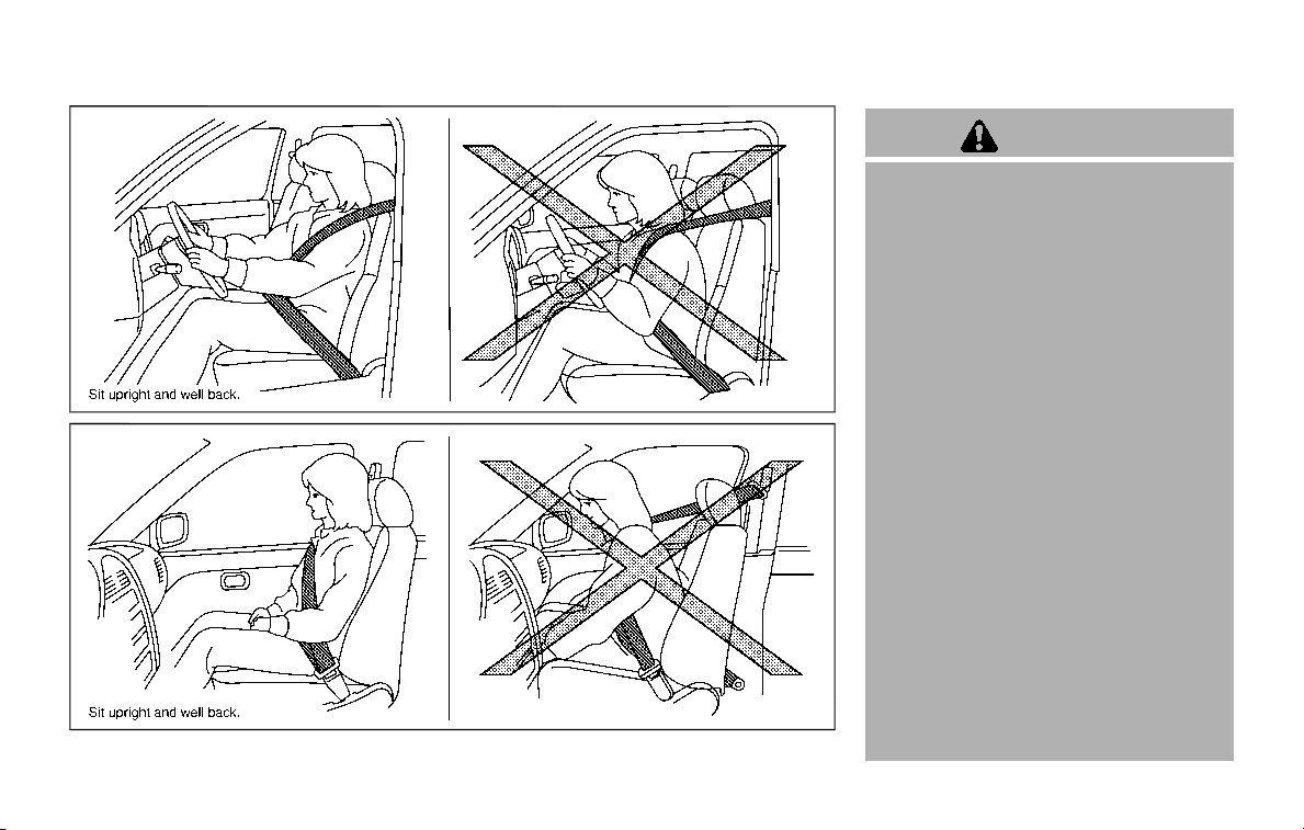
SSS0131
SSS0132
WARNING
. The front air bags ordinarily will
not inflate in the event of a side
impact, rear impact, rollover, or
lower severity frontal collision.
Always wear your seat belts to
help reduce the risk or severity of
injury in various kinds of acci-
dents.
. The front passenger air bag will
not inflate if the front passenger
air bag status light is lit or if the
front passenger seat is unoccu-
pied. See “Front passenger air
bag and status light” (P.1-62).
. The seat belts and the front air
bags are most effective when you
are sitting well back and upright
in the seat. The front air bags
inflate with great force. Even with
the NISSAN Advanced Air Bag
System, if you are unrestrained,
leaning forward, sitting sideways
or out of position in any way, you
are at greater risk of injury or
death in a crash. You may also
receive serious or fatal injuries
from the front air bag if you are
up against it when it inflates.
Always sit back against the seat-
Safety — seats, seat belts and supplemental restraint system 1-55
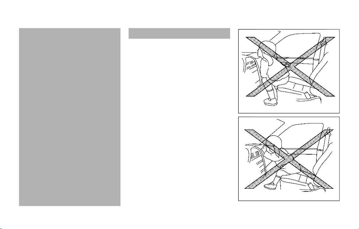
1-56 Safety — seats, seat belts and supplemental restraint system
back and as far-away as practical
from the steering wheel or instru-
ment panel. Always use the seat
belts.
. The driver and front passenger
seat belt buckles are equipped
with sensors that detect if the
seat belts are fastened. The Ad-
vanced Air Bag System monitors
the severity of a collision and seat
belt usage then inflates the air
bags. Failure to properly wear
seat belts can increase the risk
or severity of injury in an acci-
dent.
. The front passenger seat is
equipped with occupant classifi-
cation sensors (weight sensors)
that turn the front passenger air
bag OFF under some conditions.
This sensor is only used in this
seat. Failure to be properly
seated and wearing the seat belt
can increase the risk or severity
of injury in an accident. See
“Front passenger air bag and
status light” (P.1-62).
. Keep hands on the outside of the
steering wheel. Placing them in-
side the steering wheel rim could
increase the risk of injury if the
front air bag inflates.
SSS0007
SSS0006
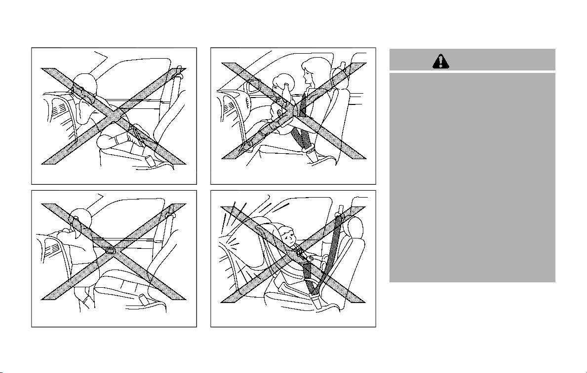
SSS0008
SSS0009
SSS0099
SSS0100
WARNING
. Never let children ride unrest-
rained or extend their hands or
face out of the window. Do not
attempt to hold them in your lap
or arms. Some examples of dan-
gerous riding positions are
shown in the illustrations.
. Children may be severely injured
or killed when the front air bags,
side air bags or curtain air bags
inflate if they are not properly
restrained. Pre-teens and chil-
dren should be properly re-
strained in the rear seat, if
possible.
. Even with the NISSAN Advanced
Air Bag System, never install a
rear-facing child restraint in the
front seat. An inflating front air
bag could seriously injure or kill
your child. See “Child restraints”
(P.1-32) for details.
Safety — seats, seat belts and supplemental restraint system 1-57
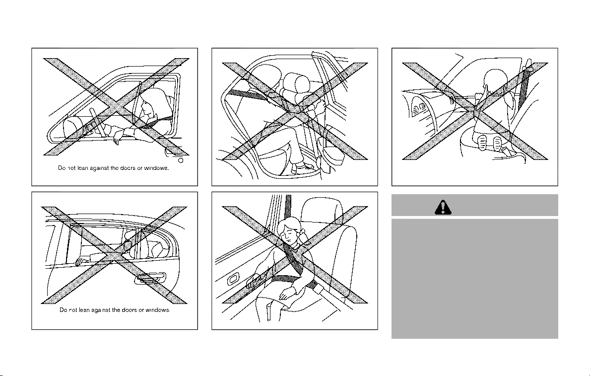
1-58 Safety — seats, seat belts and supplemental restraint system
SSS0832
SSS0833
SSS0140
SSS0162
SSS0159
WARNING
Front seat-mounted side-impact
supplemental air bags and roof-
mounted curtain side-impact and
rollover supplemental air bags:
. The side air bags ordinarily will
not inflate in the event of a front
impact, rear impact, rollover, or
lower severity side collision. Al-
ways wear your seat belts to help
reduce the risk or severity of
injury in various kinds of acci-
dents.

. The curtain air bags ordinarily will
not inflate in the event of a front
impact, rear impact, or lower
severity side collision. Always
wear your seat belts to help
reduce the risk or severity of
injury in various kinds of acci-
dents.
. The seat belts, the side air bags
and curtain air bags are most
effective when you are sitting
well back and upright in the seat.
The side air bags and curtain air
bags inflate with great force. Do
not allow anyone to place their
hand, leg or face near the side air
bags on the side of the seatback
of the front seat or near the side
roof rails. Do not allow anyone
sitting in the front seats or rear
outboard seats to extend their
hand out of the window or lean
against the door. Some examples
of dangerous riding positions are
shown in the previous illustra-
tions.
. When sitting in the rear seat, do
not hold onto the seatback of the
front seat. If the side air bag
inflates, you may be seriously
injured. Be especially careful with
children, who should always be
properly restrained. Some exam-
ples of dangerous riding posi-
tions are shown in the
illustrations.
. Do not use seat covers on the
front seatbacks. They may inter-
fere with side air bags inflation.
Safety — seats, seat belts and supplemental restraint system 1-59
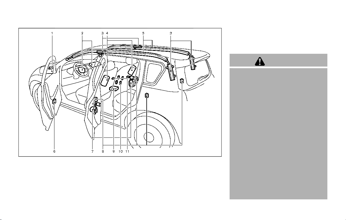
1-60 Safety — seats, seat belts and supplemental restraint system
JVR0399X
1. Crash zone sensor
2. Supplemental front-impact air bag mod-
ules (NISSAN Advanced Air Bags)
3. Roof-mounted curtain side-impact and
rollover supplemental air bag inflators
4. Front seat-mounted side-impact supple-
mental air bag modules
5. Roof-mounted curtain side-impact and
rollover supplemental air bags
6. Door satellite sensors
7. Seat belt pretensioners
8. Satellite sensors
9. Air bag Control Unit (ACU)
10. Occupant classification sensors (weight
sensors)
11. Occupant classification system control
unit
NISSAN ADVANCED AIR BAG SYS-
TEM (front seats)
WARNING
To ensure proper operation of the
passenger’s advanced air bag sys-
tem, please observe the following
items.
. Do not allow a passenger in the
rear seat to push or pull on the
seatback pocket.
. Do not place heavy loads heavier
than 9.1 lbs (4 kg) on the seat-
back, head restraint or in the
seatback pocket.
. Do not store cargo behind the
seat that can press into the seat-
back.
. Do not position the front passen-
ger seat so it contacts the rear
seat. If the front seat does con-
tact the rear seat, the air bag
system may determine a sensor
malfunction has occurred and the
front passenger air bag status
light may illuminate and the sup-
plemental air bag warning light

may flash.
. If a forward facing child restraint
is installed in the front passenger
seat, do not position the front
passenger seat so the child re-
straint contacts the instrument
panel. If the child restraint does
contact the instrument panel, the
system may determine the seat is
occupied and the passenger air
bag may deploy in a collision.
Also the front passenger air bag
status light may not illuminate.
See “Child restraints” (P.1-32) for
information about installing and
using child restraints.
. Confirm the operating condition
with the front passenger air bag
status light.
. If you notice that the front pas-
senger air bag status light is not
operating as described in this
section, it is recommended you
visit a NISSAN dealer to check the
passenger seat Advanced Air Bag
System.
. Until you have confirmed with
your dealer that your passenger
seat advanced air bag is working
properly, position the occupants
in the rear seating positions.
This vehicle is equipped with the NISSAN
Advanced Air Bag System for the driver
and front passenger seats. This system is
designed to meet certification require-
ments under U.S. regulations. It is also
permitted in Canada. All of the informa-
tion, cautions and warnings in this
manual apply and must be followed.
The driver supplemental front-impact air
bag is located in the center of the
steering wheel. The passenger supple-
mental front-impact air bag is mounted in
the instrument panel above the glove
box. The front air bags are designed to
inflate in higher severity frontal collisions,
although they may inflate if the forces in
another type of collision are similar to
those of a higher severity frontal impact.
They may not inflate in certain frontal
collisions. Vehicle damage (or lack of it) is
not always an indication of proper front
air bag operation.
The NISSAN Advanced Air Bag System
monitors information from the Air bag
Control Unit (ACU), seat belt buckle sen-
sors and the occupant classification sen-
sors (weight sensors). Inflator operation is
based on the severity of a collision and
seat belt usage for the driver. For the
front passenger, the occupant classifica-
tion sensors are also monitored. Based on
information from the sensors, only one
front air bag may inflate in a crash,
depending on the crash severity and
whether the front occupants are belted
or unbelted. Additionally, the front pas-
senger air bag may be automatically
turned OFF under some conditions, de-
pending on the information provided by
the occupant classification sensors. If the
front passenger air bag is OFF, the front
passenger air bag status light will be
illuminated (if the seat is unoccupied, the
light will not be illuminated, but the air
bag will be off). (See “Front passenger air
bag and status light” (P.1-62) for further
details.) One front air bag inflating does
not indicate improper performance of the
system.
If you have any questions about your air
bag system, it is recommended you visit a
NISSAN dealer to obtain information
about the system. If you are considering
modification of your vehicle due to a
disability, you may also contact NISSAN.
Contact information is contained in the
front of this Owner’s Manual.
When a front air bag inflates, a fairly loud
noise may be heard, followed by release
of smoke. This smoke is not harmful and
does not indicate a fire. Care should be
taken not to inhale it, as it may cause
irritation and choking. Those with a
history of a breathing condition should
get fresh air promptly.
Safety — seats, seat belts and supplemental restraint system 1-61
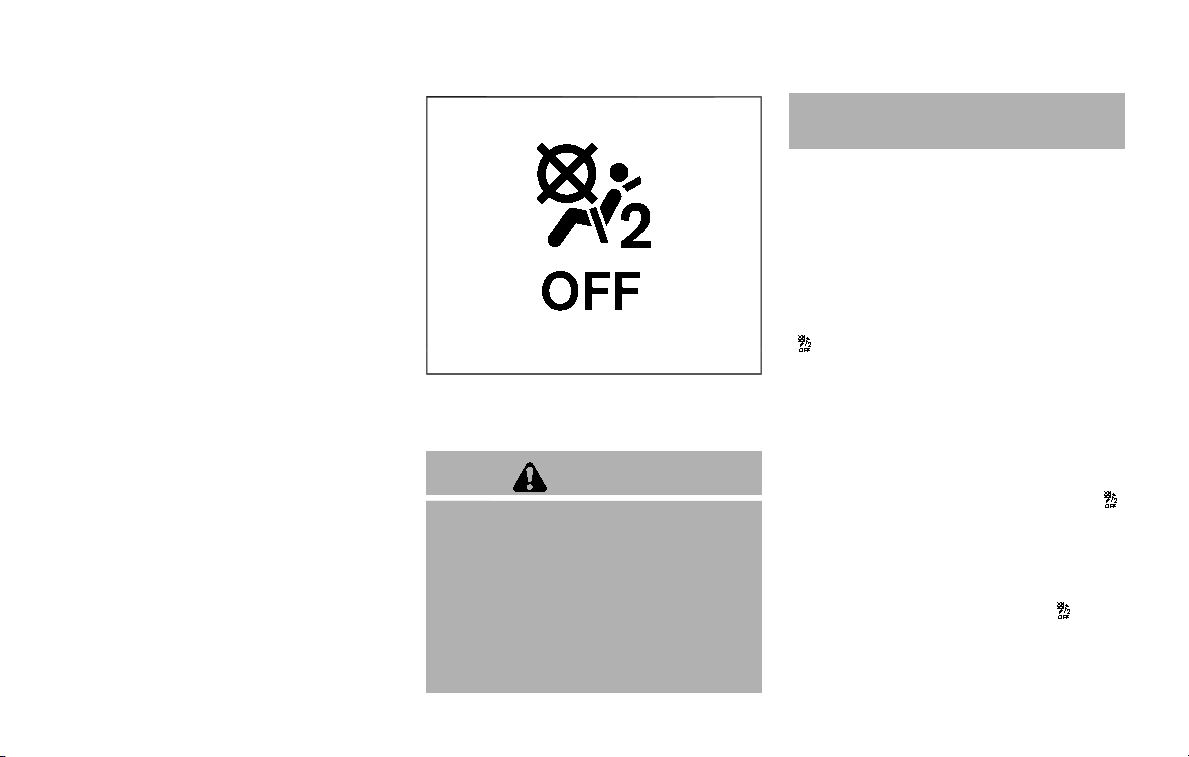
1-62 Safety — seats, seat belts and supplemental restraint system
Front air bags, along with the use of seat
belts, help to cushion the impact force on
the head and chest of the front occu-
pants. They can help save lives and
reduce serious injuries. However, an in-
flating front air bag may cause facial
abrasions or other injuries. Front air bags
do not provide restraint to the lower
body.
Even with NISSAN advanced air bags, seat
belts should be correctly worn and the
driver and passenger seated upright as
far as practical away from the steering
wheel or instrument panel. The front air
bags inflate quickly in order to help
protect the front occupants. Because of
this, the force of the front air bag inflating
can increase the risk of injury if the
occupant is too close to, or is against,
the air bag module during inflation.
The front air bags deflate quickly after a
collision.
The front air bags operate only when
the ignition switch is in the ON position.
After placing the ignition switch in the
ON position, the supplemental air bag
warning light illuminates. The supple-
mental air bag warning light will turn
off after about 7 seconds if the system
is operational.
SSS1099
Front passenger air bag status light
Front passenger air bag and status
light
WARNING
The front passenger air bag is de-
signed to automatically turn OFF
under some conditions. Read this
section carefully to learn how it
operates. Proper use of the seat,
seat belt and child restraints is ne-
cessary for most effective protec-
tion. Failure to follow all
instructions in this manual concern-
ing the use of seats, seat belts and
child restraints can increase the risk
or severity of injury in an accident.
Status light:
The front passenger seat is equipped with
the occupant classification sensors
(weight sensors) that turn the front
passenger air bag on or off depending
on the weight applied to the front pas-
senger seat. The status of the front
passenger air bag (ON or OFF) is indicated
by the front passenger air bag status light
which is located on the instrument
panel. After the ignition switch is placed in
the ON position, the front passenger air
bag status light on the instrument panel
illuminates for about 7 seconds and then
turns off or illuminates depending on the
front passenger seat occupied status.
The light operates as follows:
. Unoccupied passenger seat: The
light is OFF and the front passenger
air bag is OFF and will not inflate in a
crash.
. Passenger seat occupied by a small
adult, child or child restraint as out-
lined in this section: The
light
illuminates to indicate that the front
passenger air bag is OFF and will not
inflate in a crash.

. Occupied passenger seat and the
passenger meets the conditions out-
lined in this section: The
light is
OFF to indicate that the front passen-
ger air bag is operational.
In addition to the above, certain objects
placed on the front passenger seat may
also cause the light to operate as de-
scribed above depending on their weight.
For additional information related to the
normal operation and troubleshooting of
this occupant classification sensor sys-
tem, please refer to “Normal operation”
(P.1-64) and “Troubleshooting” (P.1-65) in
this section.
Front passenger air bag:
The front passenger air bag is designed
to automatically turn OFF when the
vehicle is operated under some condi-
tions as described below as permitted by
U.S. regulations. If the front passenger air
bag is OFF, it will not inflate in a crash. The
driver air bag and other air bags in your
vehicle are not part of this system.
The purpose of the regulation is to help
reduce the risk of injury or death from an
inflating air bag to certain front passen-
ger seat occupants, such as children, by
requiring the air bag to be automatically
turned OFF.
The occupant classification sensors
(weight sensors) are on the seat cushion
frame under the front passenger seat and
are designed to detect an occupant and
objects on the seat. For example, if a child
is in the front passenger seat, the Ad-
vanced Air Bag System is designed to turn
the passenger air bag OFF in accordance
with the regulations. Also, if a child
restraint of the type specified in the
regulations is on the seat, the occupant
classification sensors can detect it and
cause the air bag to turn OFF.
Front passenger seat adult occupants
who are properly seated and using the
seat belt as outlined in this manual
should not cause the passenger air bag
to be automatically turned OFF. For small
adults it may be turned OFF, however, if
the occupant does not sit in the seat
properly (for example, by not sitting up-
right, by sitting on an edge of the seat, or
by otherwise being out of position), this
could cause the sensor to turn the air bag
OFF. Always be sure to be seated and
wearing the seat belt properly for the
most effective protection by the seat belt
and supplemental air bag.
NISSAN recommends that pre-teens and
children be properly restrained in a rear
seat. NISSAN also recommends that ap-
propriate child restraints and booster
seats be properly installed in a rear seat.
If this is not possible, the occupant
classification sensors are designed to
operate as described above to turn the
front passenger air bag OFF for specified
child restraints. Failing to properly secure
child restrains and to use the ALR mode
may allow the restraint to tip or move in
an accident or sudden stop. This can also
result in the passenger air bag inflating in
a crash instead of being OFF. (See “Child
restraints” (P.1-32) for proper use and
installation.)
If the front passenger seat is not occu-
pied, the passenger air bag is designed
not to inflate in a crash. However, heavy
objects placed on the seat could result in
air bag inflation, because of the object
being detected by the occupant classifi-
cation sensors. Other conditions could
also result in air bag inflation, such as if a
child is standing on the seat, or if two
children are on the seat, contrary to the
instructions in this manual. Always be
sure that you and all vehicle occupants
are seated and restrained properly.
Using the front passenger air bag status
light, you can monitor when the front
passenger air bag is automatically turned
OFF with the seat occupied. The light will
not illuminate when the front passenger
seat is unoccupied.
If an adult occupant is in the seat but the
Safety — seats, seat belts and supplemental restraint system 1-63

1-64 Safety — seats, seat belts and supplemental restraint system
front passenger air bag status light is
illuminated (indicating that the air bag is
OFF), it could be that the person is a small
adult, or is not sitting on the seat
properly.
If a child restraint must be used in the
front seat, the front passenger air bag
status light may or may not be illumi-
nated, depending on the size of the child
and the type of child restraint being used.
If the front passenger air bag status light
is not illuminated (indicating that the air
bag might inflate in a crash), it could be
that the child restraint or seat belt is not
being used properly. Make sure that the
child restraint is installed properly, the
seat belt is used properly and the occu-
pant is positioned properly. If the front
passenger air bag status light is still not
illuminated, reposition the occupant or
child restraint in a rear seat.
If the front passenger air bag status light
will not illuminate even though you be-
lieve that the child restraint, the seat belts
and the occupant are properly positioned,
the system may be sensing an unoccu-
pied seat (in which case the air bag is
OFF). Your NISSAN dealer can check that
the system is OFF by using a special tool.
However, until you have confirmed with
your dealer that your air bag is working
properly, reposition the occupant or child
restraint in a rear seat.
The NISSAN Advanced Air Bag System
and front passenger air bag status light
will take a few seconds to register a
change in the front passenger seat sta-
tus. However, if the seat becomes unoc-
cupied, the front passenger air bag status
light will remain off.
If a malfunction occurs in the front
passenger air bag system, the supple-
mental air bag warning light
, located
in the meter and gauges area will blink.
Have the system checked. It is recom-
mended you visit a NISSAN dealer for this
service.
Normal operation:
In order for the occupant classification
sensor system to classify the front pas-
senger based on weight, please follow the
precautions and steps outlined below:
Precautions:
. Make sure that there are no objects
weighing over 9.1 lbs (4 kg) hanging on
the seat or placed in the seatback
pocket.
. Make sure that a child restraint or
other object is not pressing against
the rear of the seatback.
. Make sure that a rear passenger is not
pushing or pulling on the back of the
front passenger seat.
. Make sure that the front passenger
seat or seatback is not forced back
against an object on the seat or floor
behind it.
. Make sure that there is no object
placed under the front passenger
seat.
Steps:
1. Adjust the seat as outlined. (See
“Seats” (P.1-3).) Sit upright, leaning
against the seatback, and centered
on the seat cushion with your feet
comfortably extended to the floor.
2. Make sure there are no objects on
your lap.
3. Fasten the seat belt as outlined. (See
“Seat belts” (P.1-20).)
4. Remain in this position for 30 seconds
allowing the system to classify the
front passenger before the vehicle is
put into motion.
5. Ensure proper classification by check-
ing the front passenger air bag status
light.
NOTE:
This vehicle’s occupant classification
sensor system locks the classification
during driving so it is important that
you confirm that the front passenger is
properly classified prior to driving. Also,

the occupant classification sensor sys-
tem may recalculate the weight of the
occupant when the vehicle comes to a
stop (i.e. stop light, stop sign, etc.), so
the front passenger seat occupant
should continue to remain seated as
outlined above.
Troubleshooting:
If you think the front passenger air bag
status light is incorrect:
1. If the light is ON with no front passenger
and no objects on the front passenger
seat:
This may be due to the following condi-
tions that may be interfering with the
weight sensors:
. An object weighing over 9.1 lbs (4 kg)
hanging on the seat or placed in the
seatback pocket.
. A child restraint or other object press-
ing against the rear of the seatback.
. A rear passenger pushing or pulling
on the back of the front passenger
seat.
. Forcing the front seat or seatback
against an object on the seat or floor
behind it.
. An object placed under the front
passenger seat.
. An object placed between the seat
cushion and center console or be-
tween the seat cushion and the door.
If the vehicle is moving, please come to a
stop when it is safe to do so. Check and
correct any of the above conditions.
Restart the vehicle and wait 1 minute.
NOTE:
A system check will be performed dur-
ing which the front passenger air bag
status light will remain lit for about 7
seconds initially.
If the light is still ON after this, it is
recommended that the vehicle be
checked by a NISSAN dealer as soon as
possible.
2. If the light is ON with an adult occupying
the front passenger seat:
. Occupant is a small adult — the front
passenger air bag status light is func-
tioning as intended. The front passen-
ger air bag is suppressed.
However, if the occupant is not a small
adult, then this may be due to the
following conditions that may be interfer-
ing with the weight sensors:
. Occupant is not sitting upright, lean-
ing against the seatback, and cen-
tered on the seat cushion with his/her
feet comfortably extended to the
floor.
. A child restraint or other object press-
ing against the rear of the seatback.
. A rear passenger pushing or pulling
on the back of the front passenger
seat.
. Forcing the front seat or seatback
against an object on the seat or floor
behind it.
. An object placed under the front
passenger seat.
. An object placed between the seat
cushion and center console or be-
tween the seat cushion and the door.
If the vehicle is moving, please come to a
stop when it is safe to do so. Check and
correct any of the above conditions.
Restart the vehicle and wait 1 minute.
NOTE:
A system check will be performed dur-
ing which the front passenger air bag
status light will remain lit for about 7
seconds initially.
If the light is still ON after this, the person
should be advised not to ride in the front
passenger seat and it is recommended
that the vehicle be checked by a NISSAN
dealer as soon as possible.
3. If the light is OFF with a small adult, child
or child restraint occupying the front
passenger seat.
This may be due to the following condi-
Safety — seats, seat belts and supplemental restraint system 1-65

1-66 Safety — seats, seat belts and supplemental restraint system
tions that may be interfering with the
weight sensors:
. Small adult or child is not sitting
upright, leaning against the seatback,
and centered on the seat cushion with
his/her feet comfortably extended to
the floor.
. The child restraint is not properly
installed, as outlined. (See “Child re-
straints” (P.1-32).)
. An object weighing over 9.1 lbs (4 kg)
hanging on the seat or placed in the
seatback pocket.
. A child restraint or other object press-
ing against the rear of the seatback.
. A rear passenger pushing or pulling
on the back of the front passenger
seat.
. Forcing the front seat or seatback
against an object on the seat or floor
behind it.
. An object placed under the front
passenger seat.
. An object placed between the seat
cushion and center console.
If the vehicle is moving, please come to a
stop when it is safe to do so. Check and
correct any of the above conditions.
Restart the vehicle and wait 1 minute.
NOTE:
A system check will be performed dur-
ing which the front passenger air bag
status light will remain lit for about 7
seconds initially.
If the light is still OFF after this, the small
adult, child or child restraint should be
repositioned in the rear seat and it is
recommended that the vehicle be
checked by a NISSAN dealer as soon as
possible.
Other supplemental front-impact
air bag precautions
WARNING
. Do not place any objects on the
steering wheel pad or on the
instrument panel. Also, do not
place any objects between any
occupant and the steering wheel
or instrument panel. Such objects
may become dangerous projec-
tiles and cause injury if the front
air bags inflate.
. Do not place objects with sharp
edges on the seat. Also, do not
place heavy objects on the seat
that will leave permanent impres-
sions in the seat. Such objects
can damage the seat or occupant
classification sensors (weight
sensors). This can affect the op-
eration of the air bag system and
result in serious personal injury.
. Do not use water or acidic clea-
ners (hot steam cleaners) on the
seat. This can damage the seat or
occupant classification sensors.
This can also affect the operation
of the air bag system and result in
serious personal injury.
. Immediately after inflation, sev-
eral front air bag system compo-
nents will be hot. Do not touch
them; you may severely burn
yourself.
. No unauthorized changes should
be made to any components or
wiring of the supplemental air
bag system. This is to prevent
accidental inflation of the supple-
mental air bag or damage to the
supplemental air bag system.
. Do not make unauthorized
changes to your vehicle’s electri-
cal system, suspension system or
front end structure. This could
affect proper operation of the
front air bag system.
. Tampering with the air bag sys-
tem may result in serious perso-

nal injury. Tampering includes
changes to the steering wheel
and the instrument panel assem-
bly by placing material over the
steering wheel pad and above the
instrument panel or by installing
additional trim material around
the air bag system.
. Removing or modifying the front
passenger seat may affect the
function of the air bag system
and result in serious personal
injury.
. Modifying or tampering with the
front passenger seat may result
in serious personal injury. For
example, do not change the front
seats by placing material on the
seat cushion or by installing ad-
ditional trim material, such as
seat covers, on the seat that is
not specifically designed to as-
sure proper air bag operation.
Additionally, do not stow any
objects under the front passen-
ger seat or the seat cushion and
seatback. Such objects may inter-
fere with the proper operation of
the occupant classification sen-
sors.
. No unauthorized changes should
be made to any components or
wiring of the seat belt system.
This may affect the front air bag
system. Tampering with the seat
belt system may result in serious
personal injury.
. It is recommended you visit a
NISSAN dealer for work on and
around the front air bag. It is also
recommended you visit a NISSAN
dealer for installation of electrical
equipment. The Supplemental
Restraint System (SRS) wiring
harnesses* should not be modi-
fied or disconnected. Unauthor-
ized electrical test equipment
and probing devices should not
be used on the air bag system.
. A cracked windshield should be
replaced immediately by a quali-
fied repair facility. A cracked
windshield could affect the func-
tion of the supplemental air bag
system.
* The SRS wiring harness connectors are
yellow and orange for easy identifica-
tion.
When selling your vehicle, we request that
you inform the buyer about the front air
bag system and guide the buyer to the
appropriate sections in this Owner’s Man-
ual.
Safety — seats, seat belts and supplemental restraint system 1-67
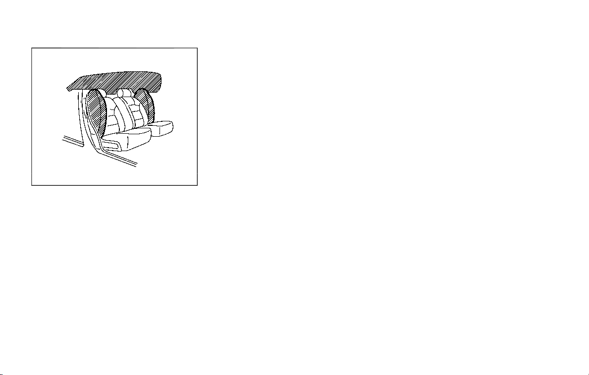
1-68 Safety — seats, seat belts and supplemental restraint system
SSS1092
FRONT SEAT-MOUNTED SIDE-IM-
PACT SUPPLEMENTAL AIR BAG AND
ROOF-MOUNTED CURTAIN SIDE-
IMPACT AND ROLLOVER SUPPLE-
MENTAL AIR BAG SYSTEMS
The side air bags are located in the
outside of the seatback of the front seats.
The curtain air bags are located in the
side roof rails. All of the information,
cautions and warnings in this manual
apply and must be followed. The side air
bags and curtain air bags are designed to
inflate in higher severity side collisions,
although they may inflate if the forces in
another type of collision are similar to
those of a higher severity side impact.
They are designed to inflate on the side
where the vehicle is impacted. They may
not inflate in certain side collisions on the
side where the vehicle is impacted.
Curtain air bags are also designed to
inflate in certain types of rollover colli-
sions or near rollovers. As a result, certain
vehicle movements (for example, during
severe off roading) may cause the curtain
air bags to inflate.
Vehicle damage (or lack of it) is not
always an indication of proper side air
bag and curtain air bag operation.
When side air bags and curtain air bags
inflate, a fairly loud noise may be heard,
followed by release of smoke. This smoke
is not harmful and does not indicate a fire.
Care should be taken not to inhale it, as it
may cause irritation and choking. Those
with a history of a breathing condition
should get fresh air promptly.
Side air bags, along with the use of seat
belts, help to cushion the impact force on
the chest and pelvis of the front occu-
pants. Curtain air bags help to cushion
the impact force to the head of occu-
pants in the front and rear (2nd and 3rd)
outboard seating positions. They can help
save lives and reduce serious injuries.
However, an inflating side air bags and
curtain air bags may cause abrasions or
other injuries. Side air bags and curtain air
bags do not provide restraint to the lower
body.
The seat belts should be correctly worn
and the driver and passenger seated
upright as far as practical away from the
side air bag. Rear seat passengers should
be seated as far away as practical from
the door finishers and side roof rails. The
side air bags and curtain air bags inflate
quickly in order to help protect the
occupants. Because of this, the force of
the side air bags and curtain air bags
inflating can increase the risk of injury if
the occupant is too close to, or is against,
these air bag modules during inflation. In
a rollover, the curtain air bags on both
sides are designed to inflate. Under both
side-impact situations, the curtain air
bags will remain inflated for a short
period of time.
The side air bags and curtain air bags
operate only when the ignition switch is
in the ON position.
After placing the ignition switch in the
ON position, the supplemental air bag
warning light illuminates. The air bag
warning light will turn off after about 7
seconds if the systems are operational.

WARNING
. Do not place any objects near the
seatback of the front seats. Also,
do not place any objects (an
umbrella, bag, etc.) between the
front door finisher and the front
seat. Such objects may become
dangerous projectiles and cause
injury if side air bag inflates.
. Right after inflation, several side
air bags and curtain air bag sys-
tem components will be hot. Do
not touch them; you may severely
burn yourself.
. No unauthorized changes should
be made to any components or
wiring of side air bag and curtain
air bags. This is to prevent da-
mage to or accidental inflation of
the side air bag and curtain air
bag systems.
. Do not make unauthorized
changes to your vehicle’s electri-
cal system, suspension system or
side panel. This could affect prop-
er operation of the side air bag
and curtain air bag systems.
. Tampering with the air bag sys-
tem may result in serious perso-
nal injury. For example, do not
change the front seats by placing
material near the seatback or by
installing additional trim materi-
al, such as seat covers, around
the side air bags.
. Removing or modifying the front
passenger seat may affect the
function of the air bag system
and result in serious personal
injury.
. It is recommended you visit a
NISSAN dealer for work on and
around the side air bag and
curtain air bag. It is also recom-
mended you visit a NISSAN dealer
for installation of electrical equip-
ment. The Supplemental Re-
straint System (SRS) wiring
harnesses* should not be modi-
fied or disconnected. Unauthor-
ized electrical test equipment
and probing devices should not
be used on the side-impact air
bag system.
* The SRS wiring harness connectors are
yellow and orange for easy identifica-
tion.
When selling your vehicle, we request that
you inform the buyer about the side air
bag and curtain air bag systems and
guide the buyer to the appropriate sec-
tions in this Owner’s Manual.
SEAT BELTS WITH PRETENSIONERS
(front seats)
WARNING
. The pretensioners cannot be re-
used after activation. They must
be replaced together with the
retractor and buckle as a unit.
. If the vehicle becomes involved in
a collision but a pretensioner is
not activated, be sure to have the
pretensioner system checked
and, if necessary, replaced. It is
recommended you visit a NISSAN
dealer for this service.
. No unauthorized changes should
be made to any components or
wiring of the pretensioner sys-
tem. This is to prevent damage to
or accidental activation of the
pretensioners. Tampering with
the pretensioner system may re-
sult in serious personal injury.
. It is recommended you visit a
NISSAN dealer for work on and
around the pretensioner system.
It is also recommended you visit a
NISSAN dealer for installation of
Safety — seats, seat belts and supplemental restraint system 1-69
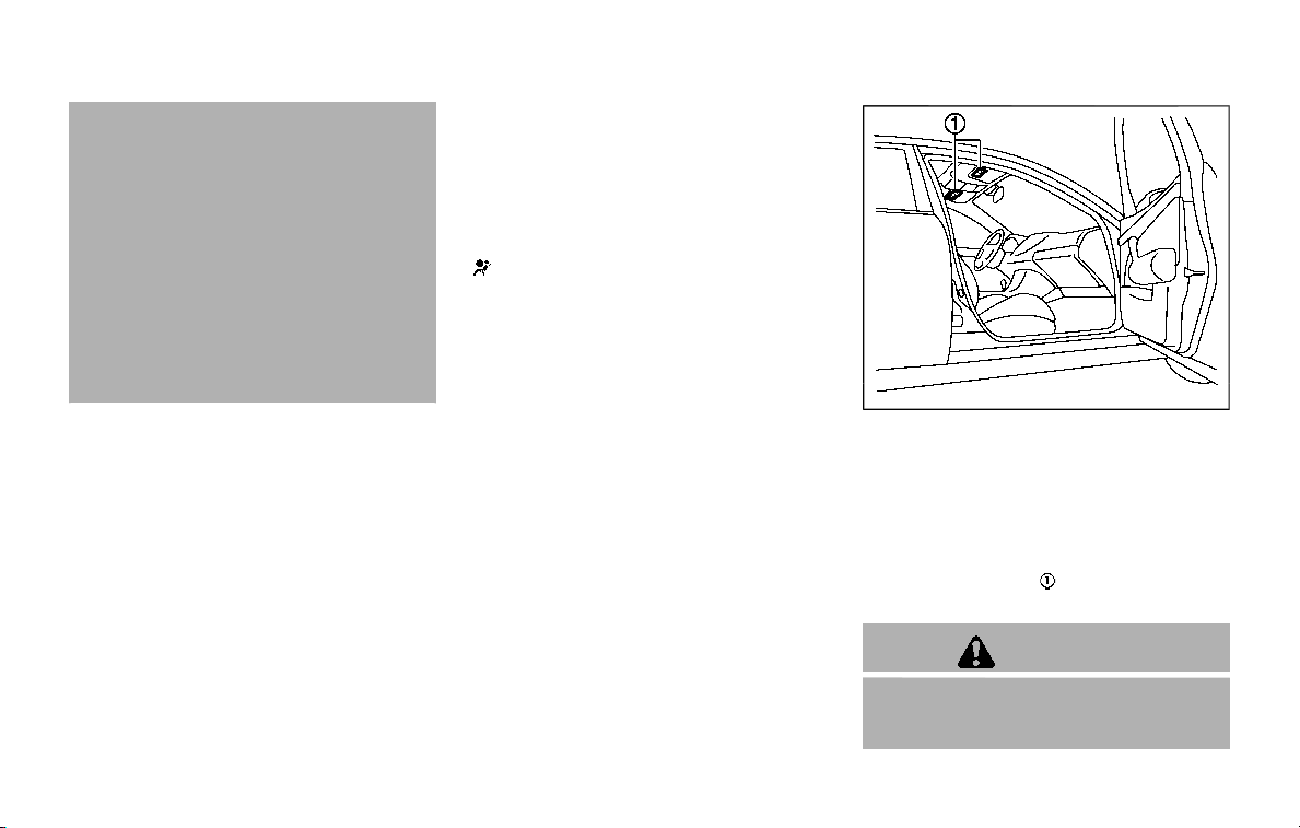
1-70 Safety — seats, seat belts and supplemental restraint system
electrical equipment. Unauthor-
ized electrical test equipment
and probing devices should not
be used on the pretensioner sys-
tem.
. If you need to dispose of a pre-
tensioner or scrap the vehicle, it is
recommended you visit a NISSAN
dealer for this service. Correct
pretensioner disposal procedures
are set forth in the appropriate
NISSAN Service Manual. Incorrect
disposal procedures could cause
personal injury.
The pretensioner system may activate
with the supplemental air bag system in
certain types of collisions. Working with
the seat belt retractor, it helps tighten the
seat belt when the vehicle becomes
involved in certain types of collisions,
helping to restrain front seat occupants.
The pretensioner is encased with the seat
belt retractor and buckle anchor. These
seat belts are used the same way as
conventional seat belts.
When a pretensioner activates, smoke is
released and a loud noise may be heard.
The smoke is not harmful, and it does not
indicate a fire. Care should be taken not
to inhale it as it may cause irritation and
choking. Those with a history of a breath-
ing condition should get fresh air
promptly.
After pretensioner activation, load limiters
allow the seat belt to release webbing (if
necessary) to reduce forces against the
chest.
The supplemental air bag warning light
is used to indicate malfunctions in
the pretensioner system. (See “Supple-
mental air bag warning light” (P.1-71) for
more details.) If the operation of the
supplemental air bag warning light indi-
cates there is a malfunction, have the
system checked. It is recommended you
visit a NISSAN dealer for this service.
When selling your vehicle, we request that
you inform the buyer about the preten-
sioner system and guide the buyer to the
appropriate sections in this Owner’s Man-
ual.
SSS1016
SUPPLEMENTAL AIR BAG WARNING
LABELS
Warning labels about the supplemental
front-impact air bag system are placed in
the vehicle as shown in the illustration.
SRS air bag
The warning labels are located on the
surface of the sun visors.
WARNING
Do not use a rear-facing child re-
straint on a seat protected by an air
bag in front of it. If the air bag

deploys, it may cause serious injury
or death.
SPA1097
SUPPLEMENTAL AIR BAG WARNING
LIGHT
The supplemental air bag warning light,
displaying
in the instrument panel,
monitors the circuits for the air bag
systems, pretensioners and all related
wiring.
When the ignition switch is in the ON
position, the supplemental air bag warn-
ing light illuminates for about 7 seconds
and then turns off. This means the system
is operational.
If any of the following conditions occur,
the air bag and/or pretensioner systems
need servicing:
. The supplemental air bag warning
light remains on after approximately
7 seconds.
. The supplemental air bag warning
light flashes intermittently.
. The supplemental air bag warning
light does not come on at all.
Under these conditions, the air bag and/
or pretensioner systems may not operate
properly. They must be checked and
repaired. It is recommended you visit a
NISSAN dealer for this service.
WARNING
If the supplemental air bag warning
light is on, it could mean that the
front air bag, side air bag, curtain air
bag and/or pretensioner systems
will not operate in an accident. To
help avoid injury to yourself or
others, have your vehicle checked
as soon as possible. It is recom-
mended you visit a NISSAN dealer
for this service.
Safety — seats, seat belts and supplemental restraint system 1-71

1-72 Safety — seats, seat belts and supplemental restraint system
REPAIR AND REPLACEMENT PRO-
CEDURE
The front air bags, side air bags, curtain
air bags and pretensioners are designed
to activate on a one-time-only basis. As a
reminder, unless it is damaged, the sup-
plemental air bag warning light will re-
main illuminated after inflation has
occurred. These systems should be re-
paired and/or replaced as soon as possi-
ble. It is recommended you visit a NISSAN
dealer for this service.
When maintenance work is required on
the vehicle, the front air bags, side air
bags, curtain air bags, pretensioners and
related parts should be pointed out to the
person conducting the maintenance. The
ignition switch should always be in the
LOCK position when working under the
hood or inside the vehicle.
WARNING
. Once a front air bag, side air bag
or curtain air bag has inflated, the
air bag module will not function
again and must be replaced. Ad-
ditionally, the activated preten-
sioner must also be replaced. The
air bag module and pretensioner
should be replaced. It is recom-
mended you visit a NISSAN dealer
for this service. However, the air
bag module and pretensioner
system cannot be repaired.
. The front air bag, side air bag,
curtain air bag and the preten-
sioner should be inspected if
there is any damage to the front
end or side portion of the vehicle.
It is recommended you visit a
NISSAN dealer for this service.
. If you need to dispose of a sup-
plemental air bag or pretensioner
or scrap the vehicle, it is recom-
mended you visit a NISSAN deal-
er. Correct supplemental air bag
and pretensioner system dispo-
sal procedures are set forth in the
appropriate NISSAN Service Man-
ual. Incorrect disposal procedures
could cause personal injury.
. If there is an impact to your
vehicle from any direction, your
Occupant Classification Sensor
(OCS) should be checked to verify
it is still functioning correctly. It is
recommended that you visit a
NISSAN dealer for this service.
The OCS should be checked even
if no air bags deploy as a result of
the impact. Failure to verify prop-
er OCS function may result in an
improper air bag deployment re-
sulting in injury or death.

2 Instruments and controls
Cockpit .................................................................................................. 2-3
Instrument panel .......................................................................... 2-4
Meters and gauges ..................................................................... 2-5
Speedometer and odometer ........................................ 2-6
Tachometer ................................................................................ 2-7
Engine coolant temperature gauge ....................... 2-7
Fuel gauge ................................................................................... 2-8
Engine oil pressure gauge .............................................. 2-8
Voltmeter...................................................................................... 2-9
Meter/ring illumination and needle sweep....... 2-9
Warning lights, indicator lights and
audible reminders ..................................................................... 2-10
Checking lights ..................................................................... 2-11
Warning lights ........................................................................ 2-11
Indicator lights ...................................................................... 2-17
Audible reminders .............................................................. 2-20
Vehicle information display ............................................... 2-20
Operational indicators .................................................... 2-23
Maintenance indicators ................................................. 2-26
Trip computer ........................................................................ 2-28
Security systems ........................................................................ 2-30
Vehicle Security System ................................................ 2-30
NISSAN Vehicle Immobilizer System .................... 2-31
Wiper and washer switch ................................................... 2-33
Windshield wiper and washer operation ...... 2-34
Rain-sensing auto wiper system (if
so equipped) ......................................................................... 2-34
Rear window wiper and
washer operation ............................................................. 2-36
Rear window and outside mirror
defroster switch ......................................................................... 2-36
Windshield deicer switch (if so equipped)............. 2-36
Headlight and turn signal switch ................................ 2-37
Headlight switch ............................................................... 2-37
Instrument brightness control .............................. 2-40
Turn signal switch ........................................................... 2-41
Fog light switch (if so equipped) ......................... 2-41
Heated steering wheel (if so equipped) .................. 2-42
Horn ..................................................................................................... 2-42
Heated seats ................................................................................. 2-43
Front (if so equipped).................................................... 2-43
Rear (if so equipped) ...................................................... 2-44
Climate controlled seats (if so equipped) ............. 2-45
Warning systems switch (if so equipped) ............. 2-46
SNOW mode switch ................................................................ 2-46
TOW mode switch .................................................................... 2-47
Vehicle Dynamic Control (VDC) OFF switch ........ 2-47

Rear door alert ............................................................................ 2-48
Turning the rear door alert
system ON/OFF .................................................................... 2-48
System operation ............................................................... 2-49
How to temporarily disable the rear door
alert system............................................................................. 2-49
Power outlet .................................................................................. 2-50
USB (Universal Serial Bus)
charging connector .......................................................... 2-52
Storage .............................................................................................. 2-53
Cup holders ............................................................................. 2-53
Sunglasses holder .............................................................. 2-55
Glove box ................................................................................... 2-56
Console box ............................................................................. 2-56
Tray ................................................................................................ 2-58
Coat hooks ............................................................................... 2-59
Luggage hooks ..................................................................... 2-59
Cargo floor box .................................................................... 2-60
Roof rack ................................................................................... 2-60
Rear bumper cover ........................................................... 2-61
Windows ............................................................................................ 2-63
Power windows .................................................................... 2-63
Moonroof (if so equipped) .................................................. 2-65
Power moonroof ................................................................. 2-65
Welcome light (if so equipped) ....................................... 2-67
Battery saver system ..................................................... 2-67
Interior lights ................................................................................. 2-68
Interior light switch ........................................................... 2-68
Console light ........................................................................... 2-69
Map lights ............................................................................... 2-69
Rear personal lights ....................................................... 2-69
Vanity mirror lights ................................................................. 2-70
Cargo light ..................................................................................... 2-70
HomeLink® Universal Transceiver (Type A) (if
so equipped) ................................................................................. 2-70
Programming HomeLink® ......................................... 2-71
Programming HomeLink® for Canadian
customers and gate openers ................................. 2-72
Operating the HomeLink®
Universal Transceiver .................................................... 2-73
Programming troubleshooting ............................. 2-73
Clearing the programmed information .......... 2-73
Reprogramming a single
HomeLink® button ........................................................... 2-73
If your vehicle is stolen ................................................ 2-74
HomeLink® Universal Transceiver (Type B) (if
so equipped) ................................................................................. 2-74
Programming HomeLink® ......................................... 2-75
Programming HomeLink® for Canadian
customers and gate openers ................................. 2-77
Operating the HomeLink®
Universal Transceiver .................................................... 2-77
Programming troubleshooting ............................. 2-77
Clearing the programmed information .......... 2-77
Reprogramming a single
HomeLink® button ........................................................... 2-78
Using the garage door
two-way communication ........................................... 2-78
If your vehicle is stolen ................................................ 2-79

WAA0101X
1. Power liftgate switch (if so equipped)
2. Heated steering wheel switch (if so
equipped)
3. Instrument brightness control switch
4. TRIP/RESET switch for twin trip odometer
5. Headlight, fog light and turn signal switch
— Headlight
— Turn signal
— Fog light (if so equipped)
6. Steering-wheel-mounted controls (left
side)
— Audio control steering switch
— Hands-Free Phone System switch
7. Trip computer switch
8. Wiper and washer switch
9. Steering-wheel-mounted controls (right
side)
— Intelligent Cruise Control (ICC) system
10. Dynamic driver assistance switch (if so
equipped)
— Intelligent Lane Intervention (I-LI) sys-
tem (if so equipped)
— Intelligent Distance Control (I-DC) sys-
tem (if so equipped)
— Intelligent Blind Spot Intervention (I-
BSI) system (if so equipped)
11. Shift lever
12. Four-Wheel Drive (4WD) shift switch (if so
equipped)/SNOW mode switch/TOW
MODE switch/Vehicle Dynamic Control
(VDC) OFF switch
13. Power liftgate main switch (if so
equipped)
14. Warning systems switch (if so equipped)
— Lane Departure Warning (LDW) (if so
equipped)
— Blind Spot Warning (BSW) (if so
equipped)
15. Rear door alert switch
16. Electric tilting/telescopic steering wheel
switch
Instruments and controls 2-3
COCKPIT
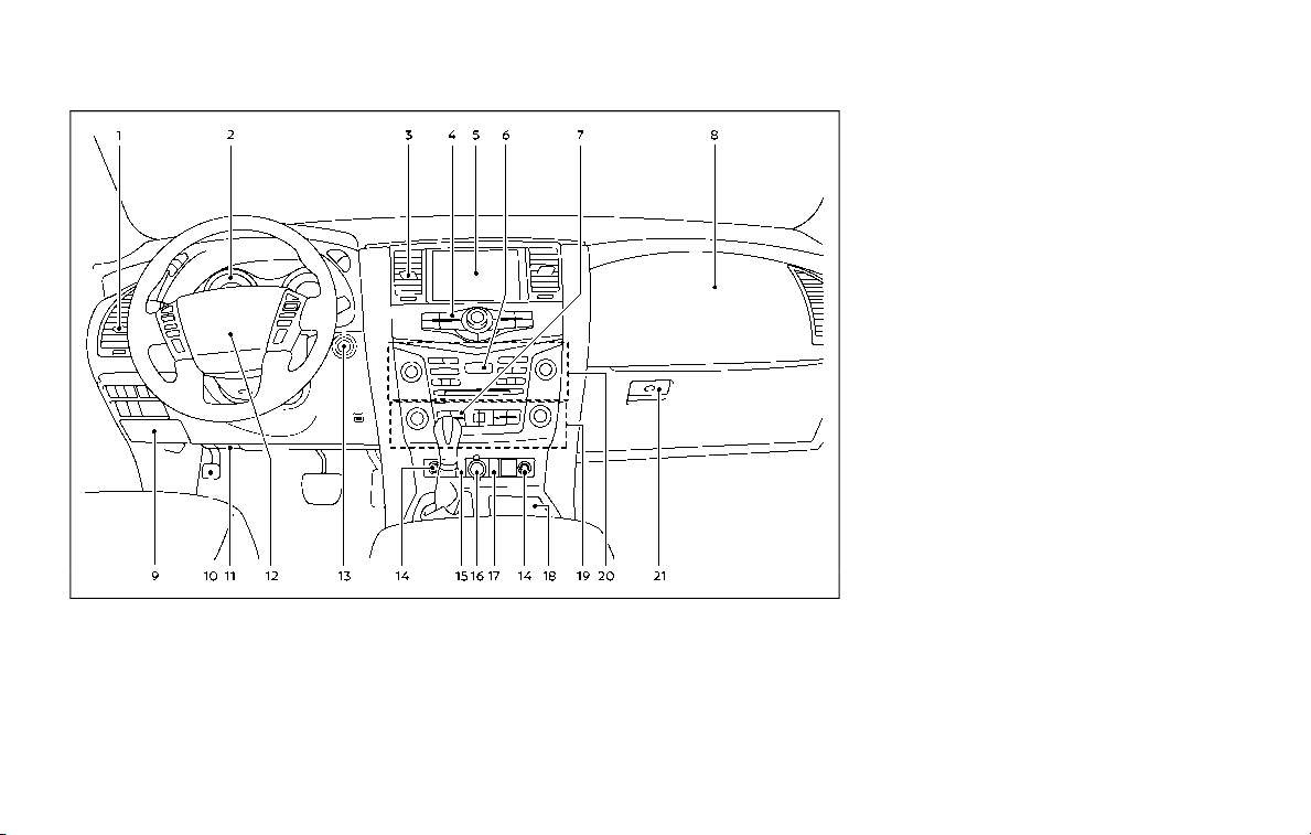
2-4 Instruments and controls
JVC1093X
1. Side ventilator
2. Meters and gauges
3. Center ventilator
4. Center multi-function control panel
5. Center display
— Intelligent Around View Monitor (if so
equipped)
— RearView Monitor (if so equipped)
— Navigation system (if so equipped)
6. Hazard warning flasher switch
7. Defroster switch/Deicer switch (if so
equipped)
8. Front passenger supplemental air bag
9. Fuse box
10. Parking brake
11. Hood release handle
12. Steering wheel
— Horn
— Driver supplemental air bag
— Power steering
13. Push-button ignition switch
14. Climate controlled seat switch (if so
equipped)/Heated seat switch (if so
equipped)
15. Front passenger air bag status light
16. Power outlet
17. USB connection port
18. Cup holder/Tray
19. Heater and air conditioner
20. Audio system
21. Glove box
INSTRUMENT PANEL
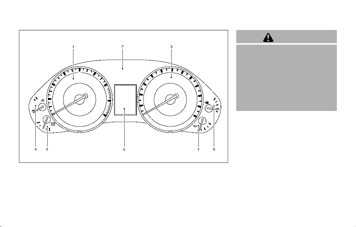
SIC4368
1. Tachometer*
2. Warning and indicator lights
3. Speedometer*
4. Engine coolant temperature gauge*
5. Voltmeter*
6. Vehicle information display/Odometer/
twin trip odometer
7. Engine oil pressure gauge*
8. Fuel gauge*
*: The needle indicators may move
slightly after the ignition switch is
placed in the OFF position. This is not
a malfunction.
CAUTION
. For cleaning, use a soft cloth,
dampened with water. Never use
a rough cloth, alcohol, benzine,
thinner or any kind of solvent or
paper towel with a chemical
cleaning agent. They will scratch
or cause discoloration to the lens.
. Do not spray any liquid such as
water on the meter lens. Spraying
liquid may cause the system to
malfunction.
Instruments and controls 2-5
METERS AND GAUGES
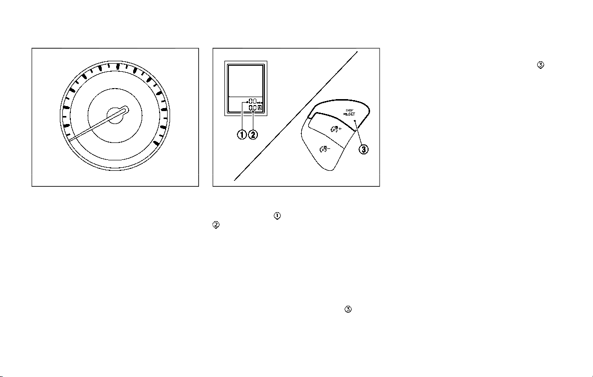
2-6 Instruments and controls
SIC4369
Speedometer
SPEEDOMETER AND ODOMETER
Speedometer
The speedometer indicates vehicle speed
in miles per hour (MPH) and kilometers
per hour (km/h).
JVI0543X
Odometer/twin trip odometer
Odometer/twin trip odometer
The odometer and twin trip odometer
are displayed on the vehicle informa-
tion display when the ignition switch is in
the ON position.
The odometer records the total distance
the vehicle has been driven.
The twin trip odometer records the dis-
tance of individual trips.
Changing the display:
Pushing the TRIP RESET switch
at the
bottom left of the combination meter
panel changes the display as follows:
TRIP A ? TRIP B ? TRIP A
Resetting the trip odometer:
Pushing the TRIP RESET switch
for
more than 1 second resets the trip
odometer to zero.
Average fuel economy and distance to
empty information is also available. (See
“Vehicle information display” (P.2-20).)
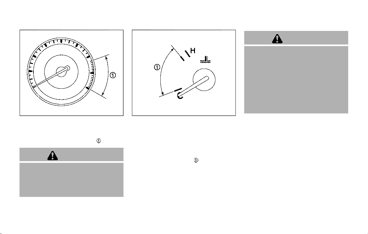
SIC4371
TACHOMETER
The tachometer indicates engine speed in
revolutions per minute (RPM). Do not rev
the engine into the red zone
.
CAUTION
When engine speed approaches the
red zone, shift to a higher gear or
reduce engine speed. Operating the
engine in the red zone may cause
serious engine damage.
SIC4372
ENGINE COOLANT TEMPERATURE
GAUGE
The gauge indicates the engine coolant
temperature.
The engine coolant temperature is within
the normal range when the gauge needle
points within the zone
shown in the
illustration.
The engine coolant temperature varies
with the outside air temperature and
driving conditions.
CAUTION
If the gauge indicates engine coolant
temperature near the hot (H) end of
the normal range, reduce vehicle
speed to decrease temperature. If
gauge is over the normal range, stop
the vehicle as soon as safely possi-
ble. If the engine is overheated,
continued operation of the vehicle
may seriously damage the engine.
See “If your vehicle overheats” (P.6-
14) for immediate action required.
Instruments and controls 2-7
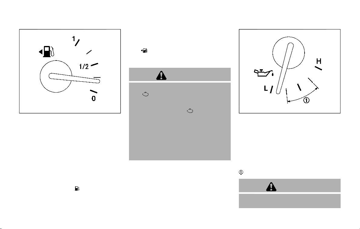
2-8 Instruments and controls
SIC4374
FUEL GAUGE
The gauge indicates the approximate
fuel level in the tank.
The gauge may move slightly during
braking, turning, acceleration, or going
up or down hills.
The gauge needle returns to 0 (Empty)
after the ignition switch is placed in the
OFF position.
Refill the fuel tank before the gauge
registers “0” (Empty).
The low fuel warning
appears on the
vehicle information display when the fuel
tank is getting low. Refuel as soon as it is
convenient, preferably before the gauge
reaches “0”. There will be a small reserve
of fuel in the tank when the fuel gauge
needle reaches “0”.
The
indicates that the fuel-filler door
is located on the driver’s side of the
vehicle.
CAUTION
. If the vehicle runs out of fuel, the
malfunction indicator light
(MIL) may come on. Refuel as
soon as possible. After a few
driving trips, the
light should
turn off. If the light remains on
after a few driving trips, have the
vehicle inspected. It is recom-
mended you visit a NISSAN dealer
for this service.
. For additional information, see
“Malfunction Indicator Light
(MIL)” (P.2-18).
SIC4375
ENGINE OIL PRESSURE GAUGE
The gauge indicates the engine lubrica-
tion system oil pressure while the engine
is running. When the engine speed is high,
the engine oil pressure is also high. When
it is low, the gauge indicates the low (L) oil
pressure.
The engine oil pressure is normal when
the gauge needle points within the zone
shown in the illustration.
CAUTION
. This gauge is not designed to
indicate low engine oil level. Use
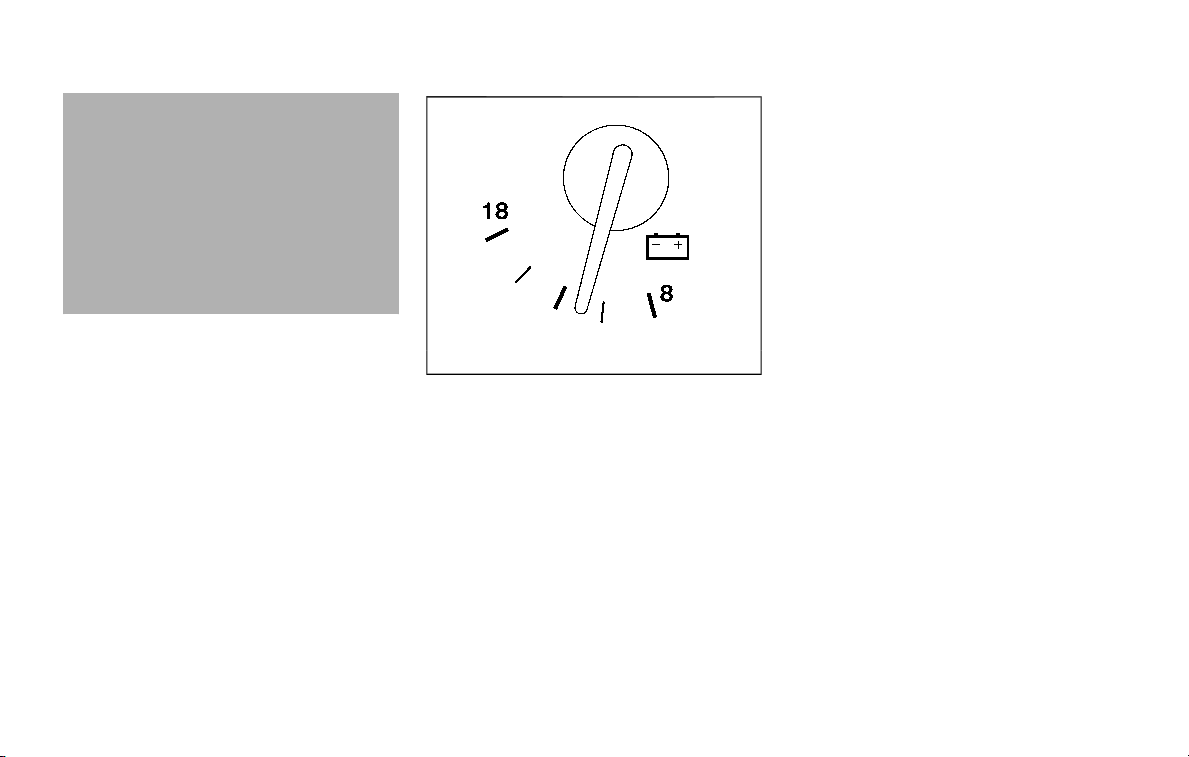
the dipstick to check the oil level.
(See “Engine oil” (P.8-6).)
. If the gauge needle does not
move with the proper amount of
engine oil, have the vehicle
checked. It is recommended you
visit a NISSAN dealer for this
service. Continued vehicle opera-
tion in such a condition could
cause serious damage to the en-
gine.
SIC4376
VOLTMETER
When the ignition switch is placed in the
ON position, the volt meter indicates the
battery voltage. When the engine is run-
ning, it indicates the generator voltage.
While cranking the engine, the volt drop
below the normal range. If the needle is
not in the normal range (10.5 to 15.5 volt)
while the engine is running, it may
indicate that the charging system is not
functioning properly. Have the system
checked. It is recommended you visit a
NISSAN dealer for this service.
METER/RING ILLUMINATION AND
NEEDLE SWEEP
The ring illumination surrounding meters
and gauges illuminates when the driver’s
door is closed after getting into the
vehicle with the Intelligent Key carried in.
When the engine is started, the indicator
needles will sweep in the speedometer
and tachometer and the ring illumination
will be brightened gradually. This function
can be turned off. (See “Trip computer”
(P.2-28).)
Instruments and controls 2-9
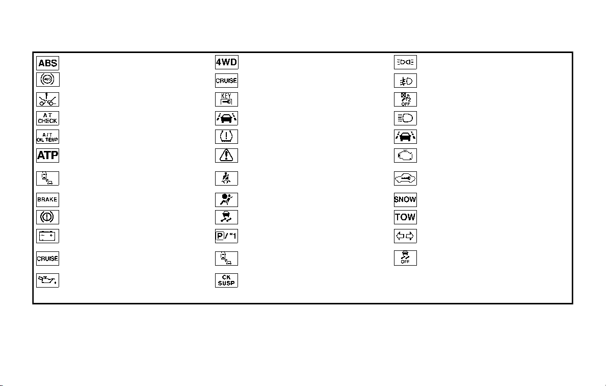
2-10 Instruments and controls
Anti-lock Braking System (ABS) warn-
ing light
Four-Wheel Drive (4WD) warning light
(4WD models)
Exterior light indicator
Intelligent Cruise Control (ICC) system
warning light (orange)
Front fog light indicator light (if so
equipped)
Automatic Emergency Braking (AEB)
system warning light
Intelligent Key warning light
Front passenger air bag status light
Automatic transmission check warn-
ing light
Lane Departure Warning (LDW) indica-
tor light (orange; if so equipped)
High beam indicator light
Automatic Transmission (AT) oil tem-
perature warning light
Low tire pressure warning light
Intelligent Lane Intervention (I-LI) ON
indicator light (green; if so equipped)
Automatic Transmission (AT) park
warning light
Master warning light
Malfunction Indicator Light (MIL)
Blind Spot Warning (BSW)/Intelligent
Blind Spot Intervention (I-BSI) system
warning light (orange; if so equipped)
Seat belt warning light
Security indicator light
Brake warning light
Supplemental air bag warning light
SNOW mode indicator light
Vehicle Dynamic Control (VDC) warn-
ing light
TOW mode indicator light
Charge warning light
Automatic transmission position indi-
cator light
Turn signal/hazard indicator lights
Intelligent Distance Control (I-DC)
system warning light (orange; if so
equipped)
Intelligent Blind Spot Intervention (I-
BSI) ON indicator light (green; if so
equipped)
Vehicle Dynamic Control (VDC) off
indicator light
Engine oil pressure warning light Check suspension indicator light
WARNING LIGHTS, INDICATOR
LIGHTS AND AUDIBLE REMINDERS
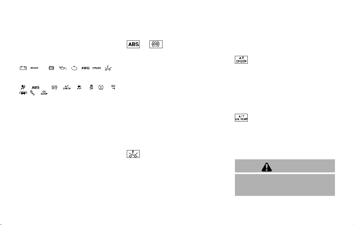
CHECKING LIGHTS
With all doors closed, apply the parking
brake, fasten the seat belts and place the
ignition switch in the ON position without
starting the engine. The following lights (if
so equipped) will come on:
, or , , , , ,
The following lights (if so equipped) will
come on briefly and then go off:
, or , , , , , ,
, ,
If any light does not come on or operates
in a way other than described, it may
indicate a burned-out bulb and/or a
system malfunction. It is recommended
you have the system checked by a
NISSAN dealer.
Some indicators and warnings are also
displayed on the vehicle information dis-
play between the speedometer and tach-
ometer. (See “Vehicle information display”
(P.2-20).)
WARNING LIGHTS
or Anti-lock Braking Sys-
tem (ABS) warning light
When the ignition switch is in the ON
position, the Anti-lock Braking System
(ABS) warning light illuminates and then
turns off. This indicates the ABS is opera-
tional.
If the ABS warning light illuminates while
the engine is running, or while driving, it
may indicate the ABS is not functioning
properly. Have the system checked. It is
recommended you visit a NISSAN dealer
for this service.
If an ABS malfunction occurs, the anti-
lock function is turned off. The brake
system then operates normally, but with-
out anti-lock assistance. (See “Brake sys-
tem” (P.5-130).)
Automatic Emergency Braking
(AEB) system warning light
This light comes on when the ignition
switch is placed in the ON position. It
turns off after the engine is started.
This light illuminates when the Automatic
Emergency Braking (AEB) system is set to
OFF on the center display.
If the light illuminates when the AEB
system is ON, it may indicate that the
system is unavailable. See “Automatic
Emergency Braking (AEB)” (P.5-98) for
more details.
Automatic Transmission (AT)
check warning light
When the ignition switch is placed in the
ON position, the light comes on for 2
seconds. If the light comes on at any
other time, it may indicate the transmis-
sion is not functioning properly. It is
recommended you visit a NISSAN dealer
to check and repair the transmission.
Automatic Transmission (AT)
oil temperature warning light
This light illuminates when the Automatic
Transmission (AT) oil temperature is too
high. If the light illuminates while driving,
reduce the vehicle speed as soon as
safely possible until the light turns off.
CAUTION
Continued vehicle operation when
the AT oil temperature warning light
is on may damage the AT.
Instruments and controls 2-11
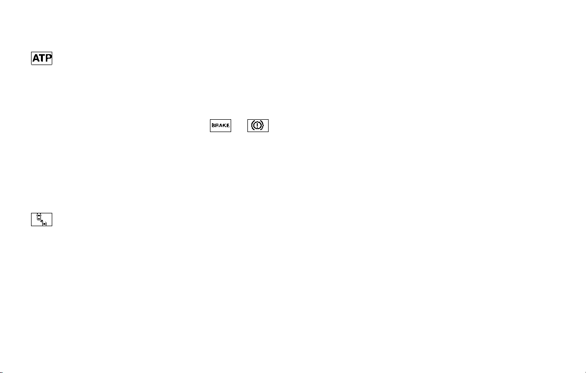
2-12 Instruments and controls
Automatic Transmission (AT)
park warning light (4WD models)
This light indicates that the Automatic
Transmission (AT) parking function is not
engaged. If the transfer control is not
secured in any driving position while the
AT shift lever is in the “P” (Park) position,
the transmission will disengage and the
wheels will not lock.
If the AT park warning light illuminates
with the shift lever in the P (Park)
position, shift the Four-Wheel Drive
(4WD) shift switch to the AUTO, 4H or
4L position again with the shift lever in
the N (Neutral) position. (See “NISSAN all-
mode 4WD®” (P.5-116).)
Blind Spot Warning (BSW)/
Intelligent Blind Spot Intervention
(I-BSI) system warning light (or-
ange; if so equipped)
When the ignition switch is placed in the
ON position, the indicator light will first
illuminate in orange and turn green
before turning off. This indicates that
the Blind Spot Warning (BSW) and Intelli-
gent Blind Spot Intervention (I-BSI) sys-
tems are operational.
If the light comes on in orange and
remains on, it may indicate that the BSW
and I-BSI systems are not functioning
properly. Although the vehicle is still
driveable, have the systems checked. It
is recommended you visit a NISSAN dealer
for this service. See “Blind Spot Warning
(BSW)” (P.5-32) and “Intelligent Blind Spot
Intervention (I-BSI)” (P.5-40).
or Brake warning light
This light functions for both the parking
brake and the foot brake systems.
Parking brake indicator:
When the ignition switch is in the ON
position, the light comes on when the
parking brake is applied.
Low brake fluid warning light:
When the ignition switch is in the ON
position, the light warns of a low brake
fluid level. If the light comes on while the
engine is running with the parking brake
not applied, stop the vehicle and perform
the following:
1. Check the brake fluid level. If brake
fluid is low, add fluid and have the
system checked. It is recommended
you have this service performed by a
NISSAN dealer. (See “Brake fluid” (P.8-
9).)
2. If the brake fluid level is correct, have
the warning system checked. It is
recommended you have this service
performed by a NISSAN dealer.
Low hydraulic pressure warning indica-
tor:
If the brake warning light illuminates
when the engine is running, or while
driving with the parking brake is released,
check the brake fluid level. If the brake
fluid level is sufficient, it may indicate low
hydraulic pressure in the brake booster. It
is recommended that you have the brake
system checked by a NISSAN dealer
promptly.
Anti-lock Braking System (ABS) warning
indicator:
When the parking brake is released and
the brake fluid level is sufficient, if both
the brake warning light and the Anti-lock
Braking System (ABS) warning light illu-
minate, it may indicate the ABS is not
functioning properly. Have the brake
system checked, and if necessary re-
paired. It is recommended you visit a
NISSAN dealer for this service. (See “Anti-
lock Braking System (ABS) warning light”
(P.2-11).)
WARNING
. Your brake system may not be
working properly if the warning
light is on. Driving could be dan-
gerous. If you judge it to be safe,
drive carefully to the nearest
service station for repairs. Other-
wise, have your vehicle towed
because driving it could be dan-
gerous.
. Pressing the brake pedal with the
engine stopped and/or low brake
fluid level may increase your
stopping distance and braking
will require greater pedal effort
as well as pedal travel.
. If the brake fluid level is below the
minimum or MIN mark on the
brake fluid reservoir, do not drive
until the brake system has been
checked. It is recommended you
visit a NISSAN dealer for this
service.
Charge warning light
If the light comes on while the engine is
running, it may indicate the charging
system is not functioning properly. Turn
the engine off and check the alternator
belt. If the belt is loose, broken, missing or
if the light remains on, have your vehicle
serviced immediately. It is recommended
you visit a NISSAN dealer for this service.
CAUTION
Do not continue driving if the alter-
nator belt is loose, broken or miss-
ing.
Intelligent Distance Control (I-
DC) system warning light (orange; if
so equipped)
This light comes on if there is a malfunc-
tion in the Intelligent Distance Control (I-
DC) system.
If the warning light illuminates, park the
vehicle in a safe place. Turn the engine off,
restart the engine, resume driving and
turn on the I-DC system again.
If it is not possible to turn on the system
or the warning light stays on, it may
indicate that the system is malfunction-
ing. Although the vehicle is still drive-
able under normal conditions, have the
vehicle checked. It is recommended you
visit a NISSAN dealer for this service.
See “Intelligent Distance Control (I-DC)”
(P.5-85).
Engine oil pressure warning
light
This light warns of low engine oil pres-
sure. If the light flickers or comes on
during normal driving, pull off the road in
a safe area, stop the engine immediately
and call a NISSAN dealer or other author-
ized repair shop.
The engine oil pressure warning light is
not designed to indicate a low oil level.
Use the dipstick to check the oil level.
(See “Engine oil” (P.8-6).)
CAUTION
Running the engine with the engine
oil pressure warning light on could
cause serious damage to the engine
almost immediately. Such damage is
not covered by warranty. Turn off the
engine as soon as it is safe to do so.
Instruments and controls 2-13
2-14 Instruments and controls
Four-Wheel Drive (4WD) warn-
ing light (4WD models)
The warning light comes on when the
ignition switch is placed in the ON posi-
tion. It turns off soon after the engine is
started.
If the 4WD system malfunctions, or the
diameter of the front and the rear wheels
are different, the warning light will either
remain illuminated or blink. (See “NISSAN
all-mode 4WD®” (P.5-116).)
CAUTION
. If the warning light comes on
while driving there may be a
malfunction in the 4WD system.
Reduce the vehicle speed and
have your vehicle checked as
soon as possible. It is recom-
mended you visit a NISSAN dealer
for this service.
. If the 4WD warning light turns on
when driving on dry or hard
surfaced roads:
— in the 4H(I) position, shift the
4WD shift switch to AUTO
— in the 4L(O) position, stop the
vehicle and shift the transmis-
sion shift lever to the N (Neu-
tral) position and shift the
4WD shift switch to AUTO
. If the warning light is still on after
the above operations, have your
vehicle checked as soon as pos-
sible. It is recommended you visit
a NISSAN dealer for this service.
Intelligent Cruise Control (ICC)
system warning light (orange)
This light comes on if there is a malfunc-
tion in the Intelligent Cruise Control (ICC)
system.
If the warning light comes on, park the
vehicle in a safe place. Turn the engine off,
restart the engine, resume driving and set
the ICC system again.
If it is not possible to set the system or
the indicator stays on, it may indicate
that the system is malfunctioning.
Although the vehicle is still driveable
under normal conditions, have the ve-
hicle checked. It is recommended you
visit a NISSAN dealer for this service.
Intelligent Key warning light
After the ignition switch is placed in the
ON position, this light comes on for about
2 seconds and then turns off.
This light warns of a malfunction with the
Intelligent Key system.
If the light comes on while the engine is
stopped, it may be impossible to start the
engine. If the light comes on while the
engine is running, you can drive the
vehicle. However in these cases, have
the system checked as soon as possible.
It is recommended you visit a NISSAN
dealer for this service.
Lane Departure Warning (LDW)
indicator light (orange; if so
equipped)
When the ignition switch is placed in the
ON position, the light will come on in
orange, turn green, and then turn off. This
indicates that the Lane Departure Warn-
ing (LDW) and Intelligent Lane Interven-
tion (I-LI) systems are operational.
While the LDW and/or I-LI system is on,
the light will blink in orange and a
warning chime will sound if the vehicle is
traveling close to either the left or the
right of a traveling lane with detectable
lane markers.

If the light comes on in orange and
remains on, it may indicate that the LDW
and I-LI systems are not functioning
properly. Although the vehicle is still
driveable, have the systems checked. It
is recommended you visit a NISSAN dealer
for this service.
See “Lane Departure Warning (LDW)/In-
telligent Lane Intervention (I-LI)” (P.5-23).
Low tire pressure warning
light
Your vehicle is equipped with a Tire
Pressure Monitoring System (TPMS) that
monitors the tire pressure of all tires
except the spare.
The low tire pressure warning light warns
of low tire pressure or indicates that the
TPMS is not functioning properly.
After the ignition switch is placed in the
ON position, this light illuminates for
about 1 second and turns off.
Low tire pressure warning:
If the vehicle is being driven with low tire
pressure, the warning light will illuminate.
A CHECK TIRE PRESSURE warning also
appears in the vehicle information dis-
play. If you select the tire pressure in-
formation in the center display, the Low
Pressure information will be displayed.
The tire pressure for each tire will also
be displayed.
When the low tire pressure warning light
illuminates, you should stop and adjust
the tire pressure to the recommended
COLD tire pressure shown on the Tire and
Loading Information label. The low tire
pressure warning light does not automa-
tically turn off when the tire pressure is
adjusted. After the tire is inflated to the
recommended pressure, the vehicle must
be driven at speeds above 16 MPH (25
km/h) to activate the TPMS and turn off
the low tire pressure warning light. Use a
tire pressure gauge to check the tire
pressure.
The CHECK TIRE PRESSURE warning ap-
pears each time the ignition switch is
placed in the ON position as long as the
low tire pressure warning light remains
illuminated.
For additional information, see “Vehicle
information display” (P.2-20), “Tire Pres-
sure Monitoring System (TPMS)” (P.5-5)
and “Tire Pressure Monitoring System
(TPMS) ” (P.6-3).
TPMS malfunction:
If the TPMS is not functioning properly,
the low tire pressure warning light will
flash for approximately 1 minute when the
ignition switch is placed in the ON posi-
tion. The light will remain on after 1
minute. Have the system checked. It is
recommended you visit a NISSAN dealer
for this service. The CHECK TIRE PRES-
SURE warning does not appear if the low
tire pressure warning light illuminates to
indicate a TPMS malfunction.
For additional information, see “Tire Pres-
sure Monitoring System (TPMS)” (P.5-5).
WARNING
. If the light does not illuminate
with the ignition switch placed in
the ON position, have the vehicle
checked as soon as possible. It is
recommended you visit a NISSAN
dealer for this service.
. If the light illuminates or Low
Pressure information is displayed
on the monitor screen while driv-
ing, avoid sudden steering man-
euvers or abrupt braking, reduce
vehicle speed, pull off the road to
a safe location and stop the
vehicle as soon as possible. Driv-
ing with under-inflated tires may
permanently damage the tires
and increase the likelihood of tire
failure. Serious vehicle damage
could occur and may lead to an
Instruments and controls 2-15
2-16 Instruments and controls
accident and could result in ser-
ious personal injury. Check the
tire pressure for all four tires.
Adjust the tire pressure to the
recommended COLD tire pressure
shown on the Tire and Loading
Information label to turn the low
tire pressure warning light OFF. If
the light still illuminates while
driving after adjusting the tire
pressure, a tire may be flat or
the TPMS may be malfunctioning.
If you have a flat tire, replace it
with a spare tire as soon as
possible. If no tire is flat and all
tires are properly inflated, it is
recommended you consult a
NISSAN dealer.
. Since the spare tire is not
equipped with the TPMS, when a
spare tire is mounted or a wheel
is replaced, the TPMS will not
function and the low tire pressure
warning light will flash for ap-
proximately 1 minute. The light
will remain on after 1 minute.
Have your tires replaced and/or
TPMS system reset as soon as
possible. It is recommended you
visit a NISSAN dealer for these
services.
. Replacing tires with those not
originally specified by NISSAN
could affect the proper operation
of the TPMS.
CAUTION
. The TPMS is not a substitute for
the regular tire pressure check.
Be sure to check the tire pressure
regularly.
. If the vehicle is being driven at
speeds of less than 16 MPH (25
km/h), the TPMS may not operate
correctly.
. Be sure to install the specified
size of tires to the four wheels
correctly.
Master warning light
When the ignition switch is in the ON
position, the master warning light illumi-
nates if any of the following are displayed
on the vehicle information display:
. No key warning
. Low fuel warning
. Low washer fluid warning
. Parking brake release warning
. Door/liftgate open warning
. Front radar obstruction warning
. Headlight warning
. Loose fuel cap warning
. Check tire pressure warning
. Intelligent Back-up Intervention (I-BI)
not available warning (if so equipped)
. Intelligent Back-up Intervention (I-BI)
malfunction warning (if so equipped)
. Automatic Emergency Braking (AEB)
system warning
. Extended storage fuse warning (if so
equipped)
See “Vehicle information display” (P.2-20).
Seat belt warning light and
chime
The light and chime remind you to fasten
seat belts. The light illuminates whenever
the ignition switch is placed in the ON
position, and will remain illuminated until
the driver’s seat belt is fastened. At the
same time, the chime will sound for about
6 seconds unless the driver’s seat belt is
securely fastened.
The seat belt warning light for the front
passenger will illuminate if the seat belt is
not fastened when the front passenger’s
seat is occupied. For approximately 5
seconds after the ignition switch is placed
in the ON position, the system does not
activate the warning light for the front
passenger.
See “Seat belts” (P.1-20) for precautions on
seat belt usage.
Supplemental air bag warning
light
After placing the ignition switch in the ON
position, the supplemental air bag warn-
ing light will illuminate. The supplemental
air bag warning light will turn off after
about 7 seconds if the air bag and/or
pretensioner systems are operational.
If any of the following conditions occur,
the air bag and/or pretensioner systems
needs servicing.
. The supplemental air bag warning
light remains on after approximately
7 seconds.
. The supplemental air bag warning
light flashes intermittently.
. The supplemental air bag warning
light does not come on at all.
It is recommended you visit a NISSAN
dealer for these services.
Unless checked and repaired, the supple-
mental restraint system (air bag system)
and/or the pretensioners may not func-
tion properly.
For additional information, see “Supple-
mental restraint system” (P.1-54).
WARNING
If the supplemental air bag warning
light is on, it could mean that the
front air bag, side air bag, curtain air
bag systems and/or pretensioner
systems will not operate in an acci-
dent. To help avoid injury to yourself
or others, have your vehicle checked.
It is recommended you visit a NISSAN
dealer for this service.
Vehicle Dynamic Control (VDC)
warning light
When the ignition switch is in the ON
position, the Vehicle Dynamic Control
(VDC) warning light illuminates and then
turns off.
The light will blink when the VDC system
or the traction control system is operat-
ing, thus alerting the driver that the
vehicle is nearing its traction limits. The
road surface may be slippery.
When the VDC warning light illuminates
when the VDC system is turned on, this
light alerts the driver to the fact that the
VDC system’s fail-safe mode is operating,
for example the VDC or hill start assist
system may not be functioning properly.
Have the system checked. It is recom-
mended you visit a NISSAN dealer for this
service. If a malfunction occurs in the
system, the VDC system function will be
canceled but the vehicle is still driveable.
For additional information, see “Vehicle
Dynamic Control (VDC) system” (P.5-133).
INDICATOR LIGHTS
Automatic Transmission (AT)
position indicator light
When the ignition switch is placed in the
ON position, the indicator shows the shift
lever position.
In the manual shift mode, when the
transmission does not shift to the se-
lected gear due to a transmission protec-
tion mode, the AT position indicator light
will blink and a buzzer will sound.
See “Automatic transmission” (P.5-18) for
further details.
Instruments and controls 2-17
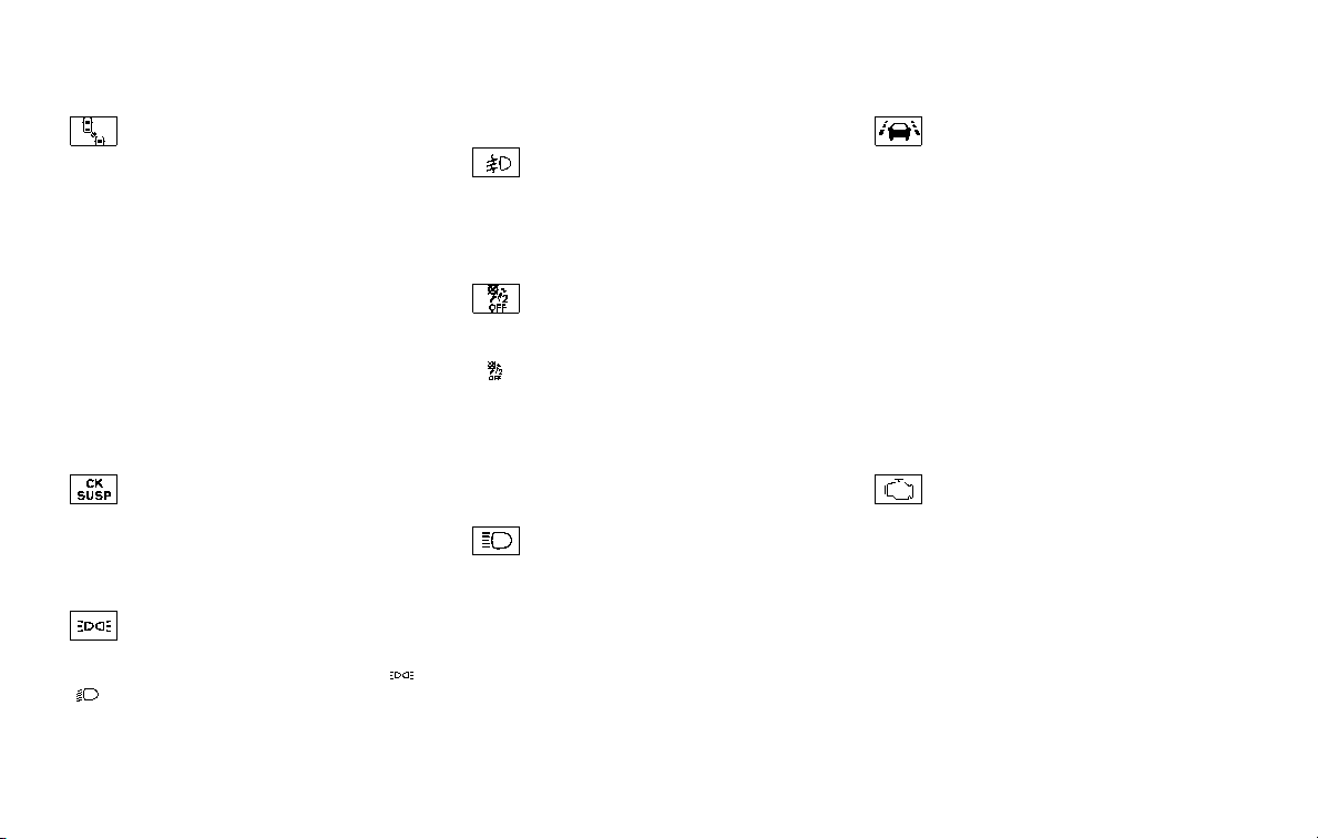
2-18 Instruments and controls
Intelligent Blind Spot Inter-
vention (I-BSI) ON indicator light
(green; if so equipped)
The light comes on in green when the
Intelligent Blind Spot Intervention (I-BSI)
system is turned on. The light turns off
when the system is turned off.
NOTE:
This light is common with the BSW/I-BSI
system warning light (orange). (See
“Blind Spot Warning (BSW)/Intelligent
Blind Spot Intervention (I-BSI) system
warning light” (P.2-12).)
For more details, see “Intelligent Blind
Spot Intervention (I-BSI)” (P.5-40).
Check suspension indicator
light
When the ignition switch is placed in the
ON position, the light comes on for 2
seconds.
Exterior light indicator
This indicator illuminates when the head-
light switch is turned to the AUTO,
or
position and the front parking lights,
instrument panel lights, rear combination
lights, license plate lights or headlights
are on. The indicator turns off when these
lights are turned off.
Front fog light indicator light
(if so equipped)
The front fog light indicator light illumi-
nates when the front fog lights are on.
(See “Fog light switch” (P.2-41).)
Front passenger air bag sta-
tus light
The front passenger air bag status light
(
) located on the instrument panel will
be lit and the passenger front air bag will
be OFF depending on how the front
passenger seat is being used.
For front passenger air bag status light
operation, see “NISSAN Advanced Air Bag
System (front seats)” (P.1-60).
High beam indicator light
This light comes on when the headlight
high beam is on and goes out when the
low beam is selected.
Intelligent Lane Intervention (I-
LI) ON indicator light (green; if so
equipped)
The light comes on in green when the
Intelligent Lane Intervention (I-LI) system
is turned on. The light turns off when the
system is turned off.
NOTE:
This light is common with the Lane
Departure Warning (LDW) indicator light
(orange). (See “Lane Departure Warning
(LDW) indicator light” (P.2-14).)
For more details, see “Lane Departure
Warning (LDW)/Intelligent Lane Interven-
tion (I-LI)” (P.5-23).
Malfunction Indicator Light
(MIL)
If the malfunction indicator light comes
on steady or blinks while the engine is
running, it may indicate a potential emis-
sion control malfunction.
The malfunction indicator light may also
come on steady if the fuel-filler cap is
loose or missing, or if the vehicle runs out
of fuel. Check to make sure the fuel-filler
cap is installed and closed tightly, and
that the vehicle has at least 3 US gallons
(14 liters) of fuel in the fuel tank.
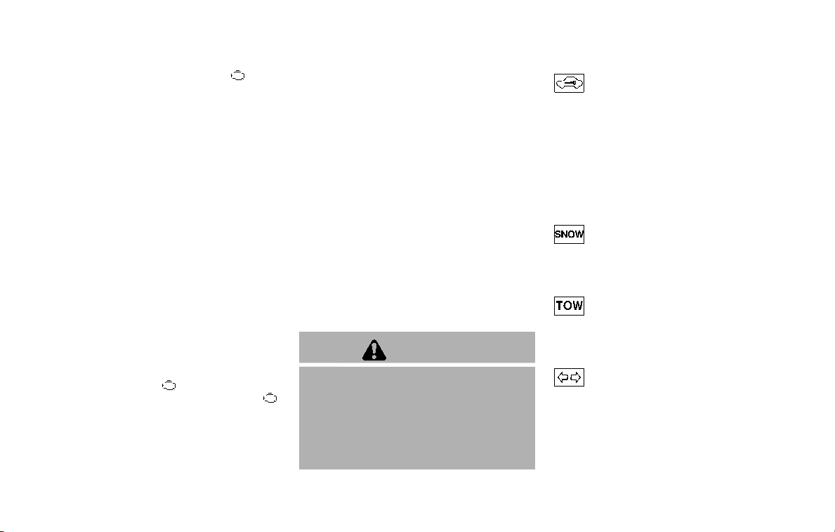
After a few driving trips, the light
should turn off if no other potential
emission control system malfunction ex-
ists.
If this indicator light remains on for 20
seconds and then blinks for 10 seconds
when the engine is not running, it indi-
cates that the vehicle is not ready for an
emission control system inspection/
maintenance test. (See “Readiness for
Inspection/Maintenance (I/M) test” (P.10-
32).)
Operation:
The malfunction indicator light will come
on in one of two ways:
. Malfunction indicator light on steady
— An emission control system mal-
function has been detected. Check
the fuel-filler cap if the LOOSE FUEL
CAP warning appears in the vehicle
information display. If the fuel-filler
cap is loose or missing, tighten or
install the cap and continue to drive
the vehicle. The
light should turn
off after a few driving trips. If the
light does not turn off after a few
driving trips, have the vehicle in-
spected. It is recommended you visit
a NISSAN dealer for this service. You
do not need to have your vehicle
towed to the dealer.
. Malfunction indicator light blinking —
An engine misfire has been detected
which may damage the emission
control system.
To reduce or avoid emission control
system damage:
1) Do not drive at speeds above 45
MPH (72 km/h).
2) Avoid hard acceleration or decel-
eration.
3) Avoid steep uphill grades.
4) If possible, reduce the amount of
cargo being hauled or towed.
The malfunction indicator light may
stop blinking and remain on.
Have the vehicle inspected. It is re-
commended you visit a NISSAN dealer
for this service. You do not need to
have your vehicle towed to the dealer.
CAUTION
Continued vehicle operation without
having the emission control system
checked and repaired as necessary
could lead to poor driveability, re-
duced fuel economy, and possible
damage to the emission control sys-
tem.
Security indicator light
The light blinks when the ignition switch
is in the ACC, OFF and LOCK position. This
function indicates the security system
equipped on the vehicle is operational.
If the security system is malfunctioning,
this light will remain on while the ignition
switch is in the ON position. For additional
information, see “Security systems” (P.2-
30).
SNOW mode indicator light
When selecting SNOW mode while the
engine is running, this light will illuminate.
(See “SNOW mode” (P.5-127).)
TOW mode indicator light
This light will illuminate when the TOW
MODE is selected while the engine is
running. (See “TOW mode” (P.5-126).)
Turn signal/hazard indicator
lights
The light flashes when the turn signal
switch lever or hazard switch is turned on.
Instruments and controls 2-19
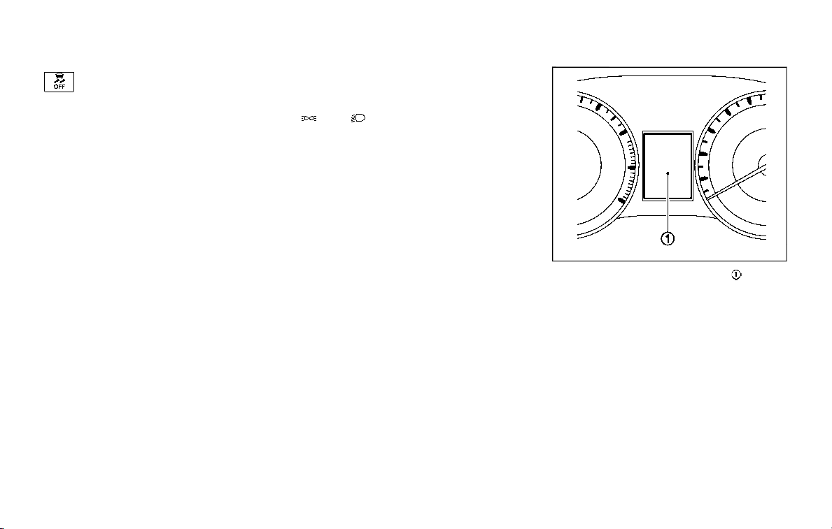
2-20 Instruments and controls
Vehicle Dynamic Control (VDC)
off indicator light
When the ignition switch is in the ON
position, the Vehicle Dynamic Control
(VDC) off indicator light illuminates and
then turns off.
The light comes on when the VDC off
switch is pushed to OFF. This indicates
that the VDC system is not operating.
When the 4L position is selected with the
Four-Wheel Drive (4WD) shift switch, the
VDC system is disabled and the VDC off
indicator light illuminates. (4WD models)
For additional information, see “Vehicle
Dynamic Control (VDC) system” (P.5-133).
AUDIBLE REMINDERS
Key reminder chime
A chime will sound if the driver side door
is opened while the ignition switch is
placed in the ACC position. Make sure
the ignition switch is placed in the OFF
position, and take the Intelligent Key with
you when leaving the vehicle.
Light reminder chime
A chime will sound when the driver side
door is opened with the light switch in the
or position and the ignition
switch in the ACC, OFF or LOCK position.
Turn the light switch off when you leave
the vehicle.
Parking brake reminder chime
The chime will sound if the vehicle is
driven at more than 4 MPH (7 km/h) with
the parking brake applied. Stop the vehi-
cle and release the parking brake.
Brake pad wear warning
The disc brake pads have audible wear
warnings. When a brake pad requires
replacement, it will make a high pitched
scraping sound when the vehicle is in
motion. This scraping sound will first
occur only when the brake pedal is
depressed. After more wear of the brake
pad, the sound will always be heard even
if the brake pedal is not depressed. Have
the brakes checked as soon as possible if
the warning sound is heard.
SIC4379
The vehicle information display located
between the speedometer and odometer,
and shows the indicators for the driving
systems, Intelligent Key operation and
various warnings and information.
For detailed information about each sys-
tem, see the following sections:
. Automatic Transmission (AT)
— “Warning lights, indicator lights and
audible reminders” (P.2-10).
— “Driving the vehicle” (P.5-17).
. Four-Wheel Drive (4WD)
— “NISSAN all-mode 4WD®” (P.5-116).
. Intelligent Back-up Intervention (I-BI)
VEHICLE INFORMATION DISPLAY

— “Intelligent Back-up Intervention (I-
BI)” (P.5-53).
. Intelligent Cruise Control (ICC)
— “Intelligent Cruise Control (ICC)”
(P.5-63).
. Intelligent Distance Control (I-DC)
— “Intelligent Distance Control (I-DC)”
(P.5-85).
. Intelligent Key system
— “Intelligent Key system” (P.3-7).
— “Push-button ignition switch” (P.5-
13).
. Automatic Emergency Braking (AEB)
— “Automatic Emergency Braking
(AEB)” (P.5-98).
. Intelligent Forward Collision Warning
(I-FCW)
— “Intelligent Forward Collision Warn-
ing (I-FCW)” (P.5-106).
Instruments and controls 2-21
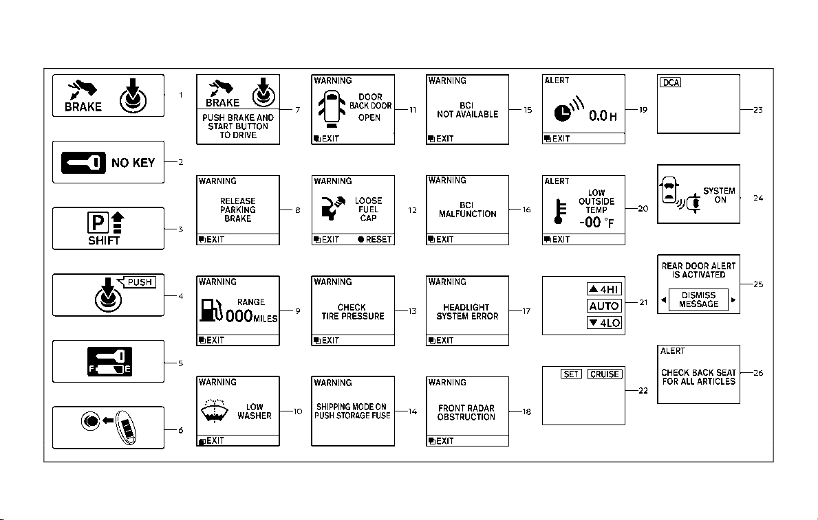
2-22 Instruments and controls
JVI1894X

OPERATIONAL INDICATORS
1. Engine start operation indicator
This indicator appears when the shift
lever is in the P (Park) position.
This indicator means that the engine will
start by pushing the ignition switch with
the brake pedal depressed.
2. NO KEY warning
This warning appears in either of the
following conditions.
No key inside the vehicle:
The warning appears when the door is
closed with the Intelligent Key left outside
the vehicle and the ignition switch in the
ACC or ON position. Make sure that the
Intelligent Key is inside the vehicle.
Unregistered Intelligent Key:
The warning appears when the ignition
switch is pushed from the LOCK position
and the Intelligent Key cannot be recog-
nized by the system. You cannot start the
engine with an unregistered key. Use the
registered Intelligent Key.
See “Intelligent Key system” (P.3-7) for
more details.
3. SHIFT “P” warning
This warning appears when the ignition
switch is pushed to stop the engine with
the shift lever in any position except the P
(Park) position.
If this warning appears, move the shift
lever to the P (Park) position or push the
ignition switch to the ON position.
An inside warning chime will also sound.
(See “Intelligent Key system” (P.3-7).)
4. “PUSH” warning
This warning appears when the shift lever
is moved to the P (Park) position with the
ignition switch in the ACC position after
the SHIFT “P” warning appears.
To push the ignition switch to the OFF
position, perform the following proce-
dure:
SHIFT “P” warning ? (Move the shift lever
to “P”) ? PUSH warning ? (Push the
ignition switch ? ignition switch position
is turned to ON) ? PUSH warning ?
(Push the ignition switch ? ignition
switch position is turned to OFF)
5. Intelligent Key battery discharge
indicator
This indicator appears when the Intelli-
gent Key battery is running out of power.
If this indicator appears, replace the
battery with a new one. (See “Intelligent
Key battery replacement” (P.8-21).)
6. Engine start operation for Intelli-
gent Key system indicator
This indicator appears when the Intelli-
gent Key battery is running out of power
and when the Intelligent Key System and
vehicle are not communicating normally.
If this indicator appears, touch the igni-
tion switch with the Intelligent Key while
depressing the brake pedal. (See “Intelli-
gent Key battery discharge” (P.5-15).)
7. Remote engine start indicator (if
so equipped)
This indicator appears when the engine
has been started using the remote engine
start function. To start the vehicle, de-
press the brake pedal and place the
ignition switch in the ON position.
For more details, see “Remote engine
start” (P.3-19).
Instruments and controls 2-23

2-24 Instruments and controls
8. Parking brake release warning
This warning appears when the vehicle
speed is above 4 MPH (7 km/h) and the
parking brake is applied.
9. Low fuel warning
This warning appears when the fuel level
in the tank is getting low. Refuel as soon
as it is convenient, preferably before the
fuel gauge reaches the 0 (Empty) position.
There is a small reserve of fuel remain-
ing in the tank when the fuel gauge
reaches the 0 (Empty) position.
10. Low washer fluid warning
This warning appears when the washer
tank fluid is at a low level. Add washer
fluid as necessary. (See “Window washer
fluid” (P.8-10).)
11. Door/liftgate open warning
(ignition switch is in the ON posi-
tion)
This warning appears if any of the doors
and/or the liftgate are open or not closed
securely. The vehicle icon indicates which
door or the liftgate is open on the display.
12. Loose fuel cap warning
This warning appears when the fuel-filler
cap is not tightened correctly after the
vehicle has been refueled. (See “Fuel-filler
cap” (P.3-27).)
13. Check tire pressure warning
This warning appears when the low tire
pressure warning light in the meter
illuminates and low tire pressure is de-
tected. The warning appears each time
the ignition switch is placed in the ON
position as long as the low tire pressure
warning light remains illuminated. If this
warning appears, stop the vehicle and
adjust the tire pressure to the recom-
mended COLD tire pressure shown on the
Tire and Loading Information label. (See
“Low tire pressure warning light” (P.2-15)
and “Tire Pressure Monitoring System
(TPMS)” (P.5-5).)
14. Extended storage fuse warning
(if so equipped)
This warning may appear if the extended
storage fuse switch is not pushed in
(switched on). When this warning ap-
pears, push in (switch on) the extended
storage fuse switch to turn off the warn-
ing. For more information, see “Extended
storage fuse switch” (P.8-21).
15. Intelligent Back-up Intervention
(I-BI) not available warning (if so
equipped)
This warning appears when the Intelli-
gent Back-up Intervention (I-BI) system is
temporarily not available.
For more details, see “Intelligent Back-up
Intervention (I-BI)” (P.5-53).
16. Intelligent Back-up Intervention
(I-BI) malfunction warning (if so
equipped)
This warning appears when the Intelli-
gent Back-up Intervention (I-BI) system is
not functioning properly.
For more details, see “Intelligent Back-up
Intervention (I-BI)” (P.5-53).
17. Headlight warning
This warning appears if the LED head-
lights are malfunctioning. It is recom-
mended you have the system checked
by a NISSAN dealer.
18. Front radar obstruction warning
This warning appears when the sensor
area of the front bumper is covered with
dirt or is obstructed, making it impossible
to detect a vehicle ahead.
The following systems will be automati-
cally canceled.

. Intelligent Cruise Control (ICC) system
. Intelligent Distance Control (I-DC) sys-
tem (if so equipped)
. Automatic Emergency Braking (AEB)
system
. Intelligent Forward Collision Warning
(I-FCW) system
For more details, see “Intelligent Cruise
Control (ICC)” (P.5-63), “Intelligent Distance
Control (I-DC)” (P.5-85), “Automatic Emer-
gency Braking (AEB)” (P.5-98) or “Intelli-
gent Forward Collision Warning (I-FCW)”
(P.5-106).
19. “TIMER” indicator
This indicator appears when the set
“TIMER” indicator activates. You can set
the time for up to 6 hours. (See “Trip
computer” (P.2-28).)
20. Low outside temperature
warning
This warning appears if the outside tem-
perature is below 37°F (3°C). The warning
can be set not to be displayed. (See “Trip
computer” (P.2-28).)
21. Four-Wheel Drive (4WD) shift
indicator (4WD models)
This indicator shows the Four-Wheel
Drive (4WD) driving mode (AUTO, 4HI or
4LO) that is selected by the 4WD shift
switch. (See “NISSAN all-mode 4WD®” (P.5-
116).)
22. Intelligent Cruise Control (ICC)
system MAIN switch indicator
The Intelligent Cruise Control (ICC) sys-
tem main switch indicator (CRUISE) is
displayed when the ICC main switch is
pushed. When the main switch is pushed
again, the indicator disappears. While the
CRUISE indicator is displayed, the ICC
system is operational.
The cruise control set indicator (SET) is
displayed while the vehicle is controlled
by the conventional (fixed speed) cruise
control mode of the ICC system.
For more details, see “Intelligent Cruise
Control (ICC)” (P.5-63).
23. Intelligent Distance Control (I-
DC) system switch indicator (if so
equipped)
The indicator is displayed when the
Intelligent Distance Control (I-DC) system
switch is pushed on. When the switch is
pushed again, the indicator disappears.
While the indicator is displayed, the I-DC
system is operational. (See “Intelligent
Distance Control (I-DC)” (P.5-85).)
24. Intelligent Back-up Intervention
(I-BI) system indicator (if so
equipped)
The I-BI ON indicator (SYSTEM ON) ap-
pears when the shift lever is in the R
(Reverse) position with the Intelligent
Back-up Intervention (I-BI) system turned
on.
If the I-BI system is turned off, the I-BI OFF
indicator (SYSTEM OFF) appears.
For more details, see “Intelligent Back-up
Intervention (I-BI)” (P.5-53).
25. Rear door alert is activated
When the rear door alert system is
enabled, this message appears when the
rear door alert system is active and can
remind the driver to check the rear seat.
NOTE:
This system is disabled until a driver
enables it using the rear door alert
switch.
For more details, see “Rear door alert”
(P.2-48).
Instruments and controls 2-25
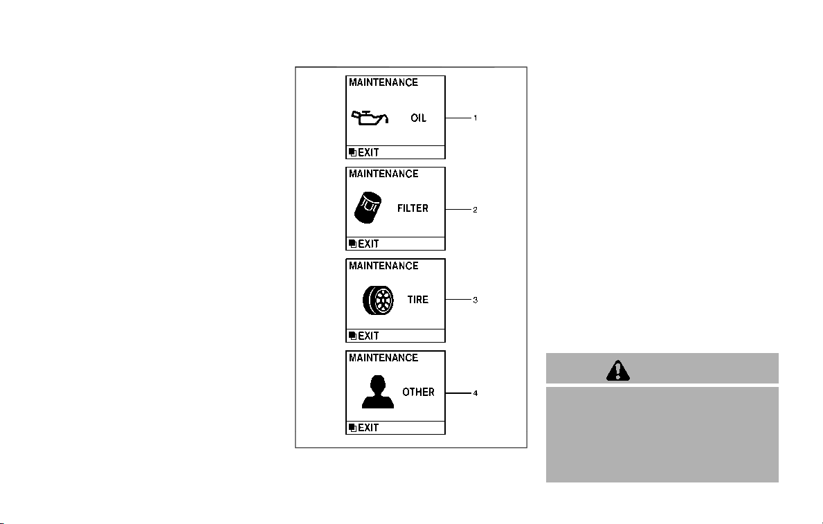
2-26 Instruments and controls
26. Check back seat for all articles
When the rear door alert system is
enabled, this message appears when the
vehicle comes to a complete stop, the
shift lever is moved from the D (Drive) or R
(Reverse) position to P (Park) position, and
the driver exits the vehicle. This message
alerts the driver, after a period of time, to
check for items in the rear seat after the
audible alert has been provided.
NOTE:
This rear door alert system is disabled
until a driver enables it using the rear
door alert switch.
For more details, see “Rear door alert”
(P.2-48).
SIC4325
MAINTENANCE INDICATORS
1. Engine oil replacement indicator
This indicator appears when the custo-
mer set time comes for changing the
engine oil. You can set or reset the
distance for changing the engine oil.
(See “Trip computer” (P.2-28).)
2. Oil filter replacement indicator
This indicator appears when the custo-
mer set time comes for replacing the oil
filter. You can set or reset the distance for
replacing the oil filter. (See “Trip compu-
ter” (P.2-28).)
3. Tire replacement indicator
This indicator appears when the custo-
mer set distance comes for replacing
tires. You can set or reset the distance
for replacing tires. (See “Trip computer”
(P.2-28).)
WARNING
The tire replacement indicator is not
a substitute for regular tire checks,
including tire pressure checks. See
“Changing wheels and tires” (P.8-37).
Many factors including tire inflation,
alignment, driving habits and road
conditions affect tire wear and when
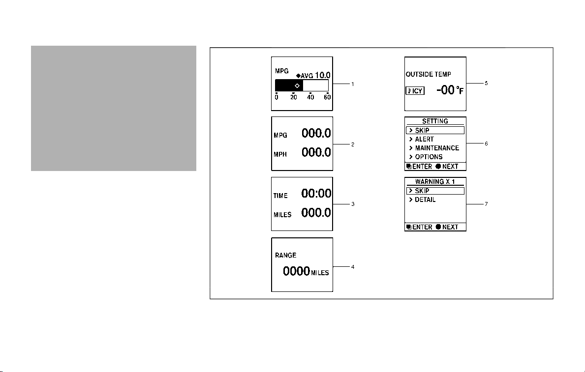
tires should be replaced. Setting the
tire replacement indicator for a cer-
tain driving distance does not mean
your tires will last that long. Use the
tire replacement indicator as a guide
only and always perform regular tire
checks. Failure to perform regular
tire checks, including tire pressure
checks could result in tire failure.
Serious vehicle damage could occur
and may lead to a collision, which
could result in serious personal in-
jury or death.
4. “OTHER” indicator
This indicator appears when the custo-
mer set time comes for replacing items
other than the engine oil, oil filter and
tires. You can set or reset the distance for
replacing the items. (See “Trip computer”
(P.2-28).)
More maintenance reminders are also
available on the center display. (See
NissanConnect® Owner’s Manual.)
SIC4494
Instruments and controls 2-27
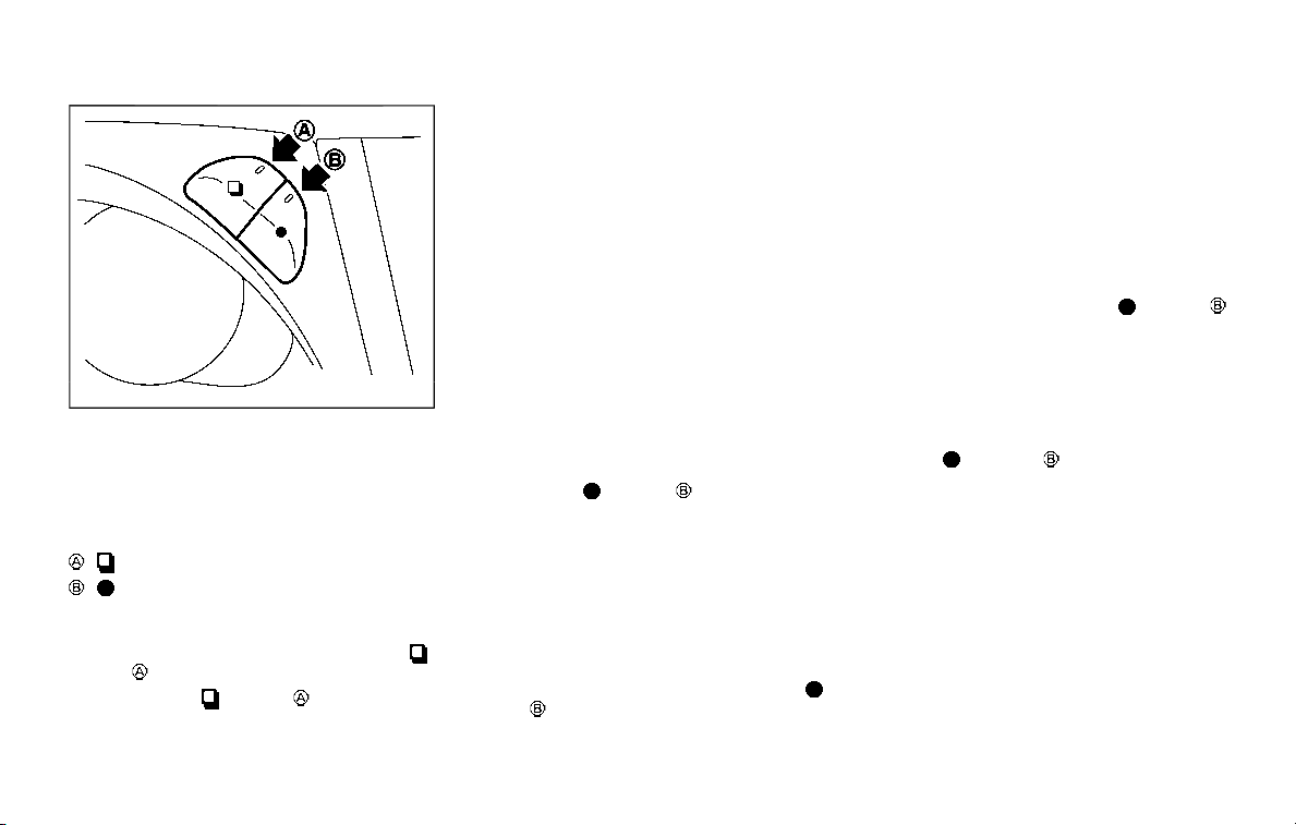
2-28 Instruments and controls
SIC4420
TRIP COMPUTER
Switches for the trip computer are lo-
cated on the right side of the combina-
tion meter panel. To operate the trip
computer, push the switches as shown
above.
switch
switch
When the ignition switch is pushed to the
ON position, modes of the trip computer
can be selected by pushing the
switch .
Each time the
switch is pushed, the
display will change as follows:
Current fuel consumption ? Average fuel
consumption and speed ? Elapsed time
and trip odometer ? Distance to empty
(dte) ? Outside air temperature (ICY) ?
Setting ? Warning check
1. Current and average fuel con-
sumption
The current and average fuel consump-
tion mode shows the current and aver-
age fuel consumption.
2. Average fuel consumption (MPG
or l (liter)/100 km) and speed (MPH
or km/h)
Fuel consumption:
The average fuel consumption mode
shows the average fuel consumption
since the last reset. Resetting is done by
pushing the
switch for longer than
1 second. (The average speed is also reset
at the same time.)
The display is updated every 30 seconds.
At about the first 1/3 mile (500 m) after a
reset, the display shows “——”.
Speed:
The average speed mode shows the
average vehicle speed since the last reset.
Resetting is done by pushing the
switch for longer than 1 second. (The
average fuel consumption is also reset at
the same time.)
The display is updated every 30 seconds.
The first 30 seconds after a reset, the
display shows “——”.
3. Elapsed time and trip odometer
(MILES or km)
Elapsed time:
The elapsed time mode shows the time
since the last reset. The displayed time
can be reset by pushing the
switch
for longer than 1 second. (The trip od-
ometer is also reset at the same time.)
Trip odometer:
The trip odometer mode shows the total
distance the vehicle has been driven since
the last reset. Resetting is done by push-
ing the
switch for longer than 1
second. (The elapsed time is also reset at
the same time.)
4. Distance to empty (dte — MILES
or km)
The distance to empty (dte) mode pro-
vides you with an estimation of the
distance that can be driven before refuel-
ing. The dte is constantly being calcu-
lated, based on the amount of fuel in the
fuel tank and the actual fuel consump-
tion.
The display is updated every 30 seconds.
The dte mode includes a low range

warning feature. If the fuel level is low, the
warning is displayed on the screen.
When the fuel level drops even lower, the
dte display will change to “——”.
. If the amount of fuel added is small,
the display just before the ignition
switch is pushed to the OFF position
may continue to be displayed.
. When driving uphill or rounding
curves, the fuel in the tank shifts,
which may momentarily change the
display.
5. Outside air temperature (ICY — °F
or °C)
The outside air temperature is displayed
in °F or °C in the range of −22 to 131°F (−30
to 55°C).
The outside air temperature mode in-
cludes a low temperature warning fea-
ture. If the outside air temperature is
below 37°F (3°C), the warning is displayed
on the screen.
The outside temperature sensor is lo-
cated in front of the radiator. The sensor
may be affected by road or engine heat,
wind directions and other driving condi-
tions. The display may differ from the
actual outside temperature or the tem-
perature displayed on various signs or
billboards.
6. Setting
Setting is available while the engine is
running.
Setting cannot be made while driving. A
message “SETTING CAN ONLY BE OPER-
ATED WHEN STOPPED” is also displayed
on the vehicle information display.
The
switch and switch are
used in the setting mode to select and
decide a menu.
SKIP:
Push the
switch to move to the
warning check mode.
Push the
switch to select other
menus.
ALERT:
There are 3 submenus under the alert
menu.
. BACK
Select this submenu to return to the
top page of the setting mode.
. TIMER
Select this submenu to specify when
the “TIMER” indicator activates.
. ICY
Select this submenu to display the low
outside temperature warning.
MAINTENANCE:
There are 5 submenus under the main-
tenance menu.
. BACK
Select this submenu to return to the
top page of the setting mode.
. TIRE
Select this submenu to set or reset the
distance for replacing tires.
. FILTER
Select this submenu to set or reset the
distance for replacing the oil filter.
. OIL
Select this submenu to set or reset the
distance for changing the engine oil.
. OTHER
Select this submenu and set or reset
the distance for replacing items other
than the engine oil, oil filter and tires.
OPTIONS:
There are 4 submenus under the display
menu.
. BACK
Select this submenu to return to the
top page of the setting mode.
. LANGUAGE
Select this submenu to choose Eng-
lish, French or Spanish for display.
Instruments and controls 2-29
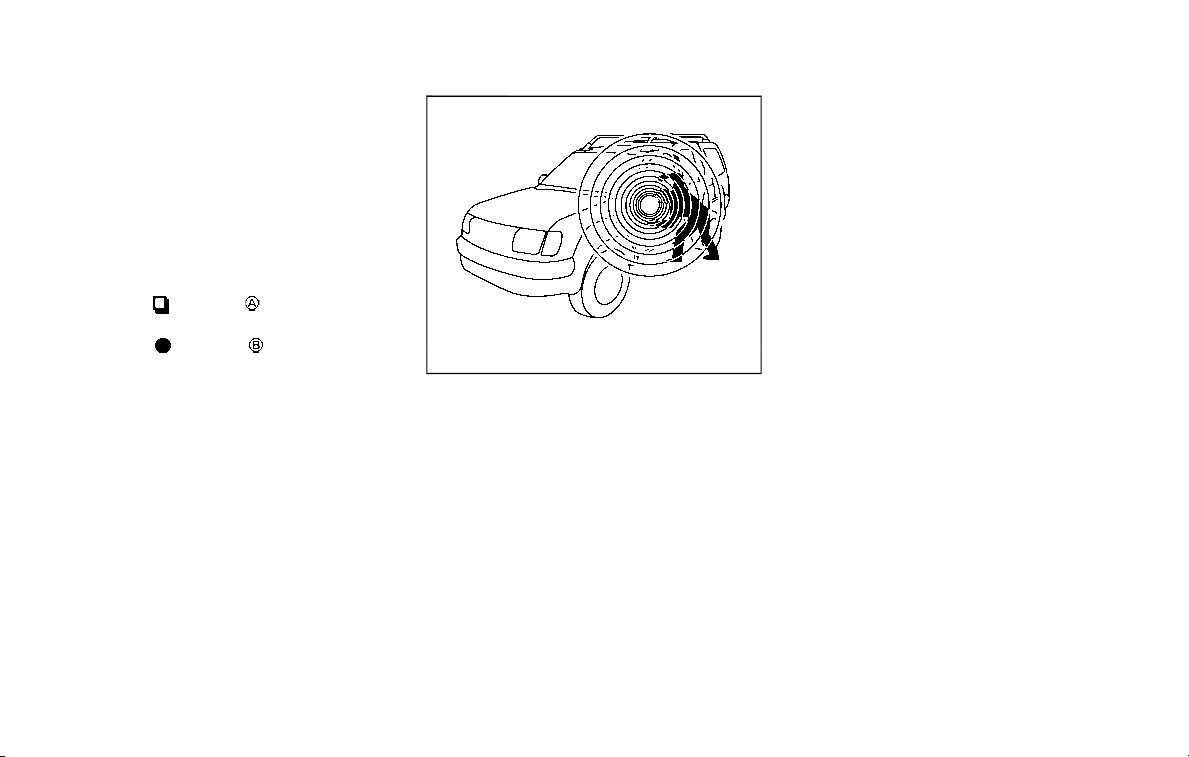
2-30 Instruments and controls
. UNIT
Select this submenu to choose the
unit.
. EFFECTS
Select this submenu to turn on and off
the needle sweep function when
starting the engine.
7. Warning check
SKIP:
Push the
switch to move to the
warning check mode.
Push the
switch to select other
menus.
DETAIL:
This item is available only when a warning
is displayed.
Select this menu to see the details of
warnings.
SIC2133
Your vehicle has two types of security
systems, as follows:
. Vehicle security system
. NISSAN Vehicle Immobilizer System
The security condition will be shown by
the security indicator light.
VEHICLE SECURITY SYSTEM
The vehicle security system provides
visual and audio alarm signals if someone
opens the doors, hood, or liftgate when
the system is armed. It is not, however, a
motion detection type system that acti-
vates when a vehicle is moved or when a
vibration occurs.
The system helps deter vehicle theft but
cannot prevent it, nor can it prevent the
theft of interior or exterior vehicle com-
ponents in all situations. Always secure
your vehicle even if parking for a brief
period. Never leave your Intelligent Key(s)
in the vehicle, and always lock it when
unattended. Be aware of your surround-
ings, and park in secure, well-lit areas
whenever possible.
Many devices offering additional protec-
tion, such as component locks, identifica-
tion markers, and tracking systems, are
available at auto supply stores and speci-
alty shops. Your NISSAN dealer may also
offer such equipment. Check with your
insurance company to see if you may be
eligible for discounts for various theft
protection features.
SECURITY SYSTEMS
SIC2045
How to arm the vehicle security
system
1. Close all windows.
The system can be armed even if the
windows are open.
2. Push the ignition switch to the OFF
position.
3. Remove the Intelligent Key from the
vehicle.
4. Close all doors, hood and liftgate. Lock
all doors. The doors can be locked
with the Intelligent Key, door handle
request switch, power door lock
switch or mechanical key.
5. Confirm that the security indicator
light comes on. The security indicator
light stays on for about 30 seconds.
The vehicle security system is now
pre-armed. After about 30 seconds
the vehicle security system automati-
cally shifts into the armed phase. The
security light begins to flash once
every approximately 3 seconds. If,
during this 30-second pre-arm time
period, the door is unlocked, or the
ignition switch is pushed to ACC or
ON, the system will not arm.
Even when the driver and/or passen-
gers are in the vehicle, the system will
activate with all doors, hood, and lift-
gate locked with the ignition switch in
the LOCK position. When pushing the
ignition switch to the ACC or ON posi-
tion, the system will be released.
Vehicle security system activation
The vehicle security system will give the
following alarm:
. The headlights blink and the horn
sounds intermittently.
. The alarm automatically turns off
after approximately 50 seconds. How-
ever, the alarm reactivates if the
vehicle is tampered with again.
The alarm is activated by:
. Unlocking the door or opening the
liftgate without using the button on
the Intelligent Key, the door handle
request switch or the mechanical key.
(Even if the door is opened by releas-
ing the door inside lock knob, the
alarm will activate.)
. Opening the hood.
How to stop an activated alarm
The alarm will stop when a door is
unlocked by pushing the unlock button
on the Intelligent Key, the door handle
request switch or using the mechanical
key, or when the ignition switch is pushed
to the ACC or ON position.
If the system does not operate as
described above, it is recommended
you have it checked by a NISSAN dealer.
NISSAN VEHICLE IMMOBILIZER SYS-
TEM
The NISSAN Vehicle Immobilizer System
will not allow the engine to start without
the use of the registered Intelligent Key.
Never leave these keys in the vehicle.
Instruments and controls 2-31
2-32 Instruments and controls
FCC Notice:
For USA:
This device complies with Part 15 of the
FCC Rules. Operation is subject to the
following two conditions: (1) This device
may not cause harmful interference,
and (2) this device must accept any
interference received, including inter-
ference that may cause undesired op-
eration.
NOTE:
Changes or modifications not expressly
approved by the party responsible for
compliance could void the user’s
authority to operate the equipment.
For Canada:
This device complies with Industry Ca-
nada licence-exempt RSS standard(s).
Operation is subject to the following
two conditions: (1) this device may not
cause interference, and (2) this device
must accept any interference, including
interference that may cause undesired
operation of the device.
SIC2045
Security indicator light
The security indicator light is located on
the meter panel. It indicates the status of
the NISSAN Vehicle Immobilizer System.
The light blinks after the ignition switch
was in the ACC, OFF and LOCK position.
This function indicates the security sys-
tems equipped on the vehicle are opera-
tional.
If the NISSAN Vehicle Immobilizer System
is malfunctioning, this light will remain on
while the ignition switch is in the ON
position.
If the light still remains on and/or the
engine will not start, seek service for
the NISSAN Vehicle Immobilizer System
as soon as possible. Please bring all
registered keys that you have. It is
recommended you visit a NISSAN dealer
for this service.
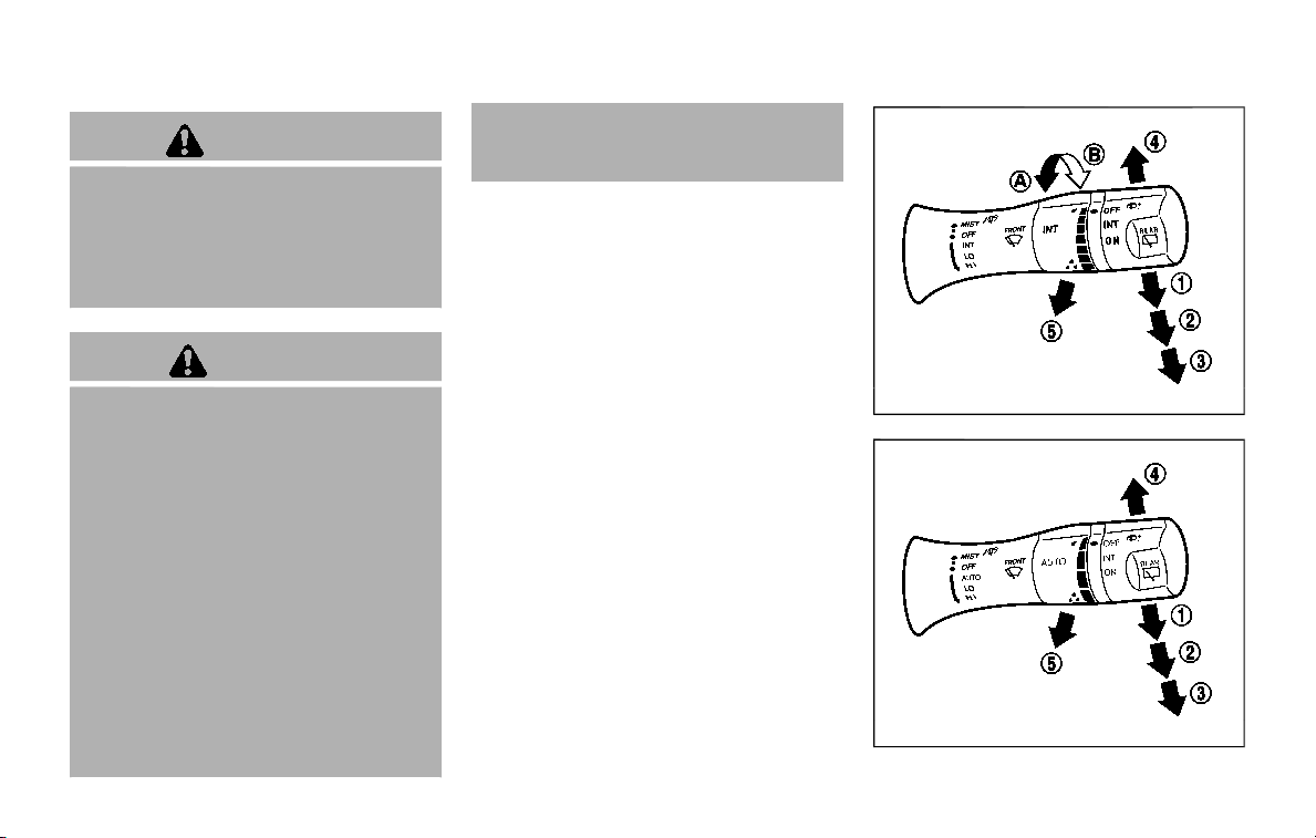
WARNING
In freezing temperatures the washer
solution may freeze on the window
and obscure your vision which may
lead to an accident. Warm the win-
dow with the defroster before you
wash the window.
CAUTION
. Do not operate the washer con-
tinuously for more than 30 sec-
onds.
. Do not operate the washer if the
reservoir tank is empty.
. Do not fill the window washer
reservoir tank with washer fluid
concentrates at full strength.
Some methyl alcohol based
washer fluid concentrates may
permanently stain the grille if
spilled while filling the window
washer reservoir tank.
. Pre-mix washer fluid concen-
trates with water to the manu-
facturer’s recommended levels
before pouring the fluid into the
window washer reservoir tank. Do
not use the window washer re-
servoir tank to mix the washer
fluid concentrate and water.
If the wiper operation is interrupted by
snow or ice, the wiper may stop moving
to protect its motor. If this occurs, turn
the wiper switch to the OFF position
and remove the snow or ice that is on
and around the wiper arms. In approxi-
mately 1 minute, turn the switch on
again to operate the wiper.
JVI1010X
Type A (if so equipped)
JVI1011X
Type B (if so equipped)
Instruments and controls 2-33
WIPER AND WASHER SWITCH
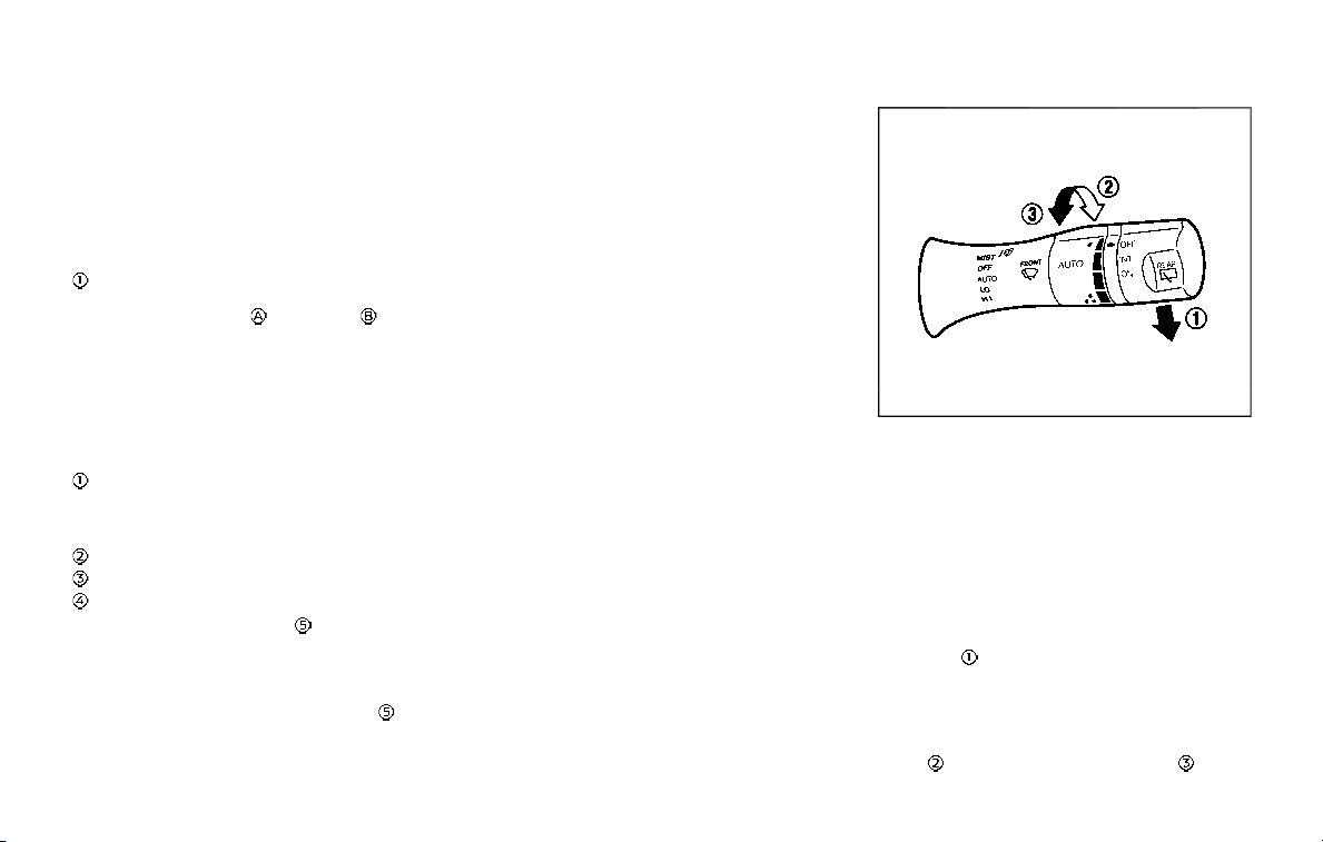
2-34 Instruments and controls
WINDSHIELD WIPER AND WASHER
OPERATION
The windshield wiper and washer oper-
ates when the ignition switch is in the ON
position.
Push the lever down to operate the wiper
at the following speed:
INT (Type A) (if so equipped) — intermit-
tent operation can be adjusted by turning
the knob toward
(Slower) or (Faster).
When the speed sensing wiper interval
function is turned on, the intermittent
operation speed varies in accordance
with the vehicle speed. (For example,
when the vehicle speed is high, the
intermittent operation speed will be fas-
ter.) To turn this function on and off, see
NissanConnect® Owner’s Manual.
AUTO (Type B) (if so equipped) — For
models with the rain-sensing auto wiper
system, see “Rain-sensing auto wiper
system” (P.2-34).
LO — continuous low speed operation
HI — continuous high speed operation
MIST — one sweep operation of the wiper
Pull the lever toward you to operate the
washer. Then the wiper will also operate
several times.
To operate the washer, pull the lever
toward the back of the vehicle
until
the desired amount of washer fluid is
spread on the windshield. The wiper will
automatically operate several times.
Wiper drip wipe system:
The wiper will also operate once about 3
seconds after the washer and wiper are
operated. This operation is to wipe
washer fluid that has dripped on the
windshield.
JVI1013X
RAIN-SENSING AUTO WIPER SYS-
TEM (if so equipped)
The rain-sensing auto wiper system can
automatically turn on the wipers and
adjust the wiper speed depending on
the rainfall and the vehicle speed by using
the rain sensor located on the upper part
of the windshield.
To set the rain-sensing auto wiper sys-
tem, push the lever down to the AUTO
position
. The wiper will sweep once
while the ignition switch is in the ON
position.
The rain sensor sensitivity level can be
adjusted by turning the knob toward the
front
(High) or toward the rear (Low).
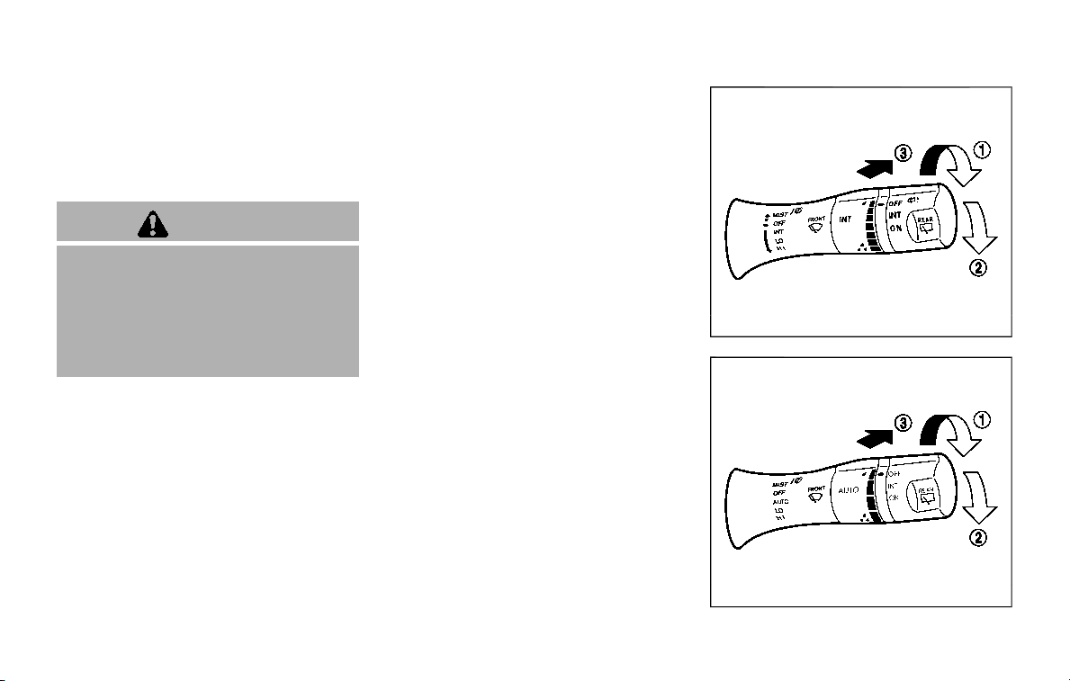
. High — High sensitive operation
. Low — Low sensitive operation
To turn the rain-sensing auto wiper
system off, push up the lever to the OFF
position, or pull down the lever to the LO
or HI position.
CAUTION
Do not touch the rain sensor and
around it when the wiper switch is in
the AUTO position and the ignition
switch is in the ON position. The
wipers may operate unexpectedly
and cause to an injury or may da-
mage a wiper.
. The rain-sensing auto wipers are
intended for use during rain. If the
switch is left in the AUTO position,
the wipers may operate unexpect-
edly when dirt, fingerprints, oil film
or insects are stuck on or around the
sensor. The wipers may also operate
when exhaust gas or moisture affect
the rain sensor.
. The rain-sensing auto wipers may
not operate if rain does not hit the
rain sensor even if it is raining.
. When the windshield glass is coated
with water repellent, the speed of
the rain-sensing auto wipers may be
higher even though the amount of
the rainfall is small.
. Be sure to turn off the rain-sensing
auto wiper system when you use a
car wash.
. Using genuine wiper blades is re-
commended for proper operation of
the rain-sensing auto wiper system.
(See “Windshield wiper blades” (P.8-
16) for wiper blade replacement.)
JVI1014X
Type A (if so equipped)
JVI1015X
Type B (if so equipped)
Instruments and controls 2-35
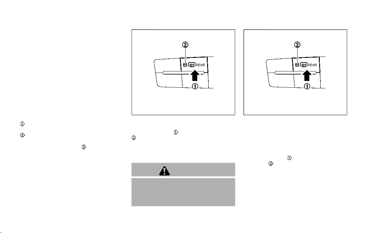
2-36 Instruments and controls
REAR WINDOW WIPER AND WASHER
OPERATION
If the rear window wiper operation is
interrupted by snow etc., the wiper may
stop moving to protect its motor. If this
occurs, turn the wiper switch to OFF and
remove the snow etc. on and around
the wiper arms. After about 1 minute,
turn the switch ON again to operate the
wiper.
The rear window wiper and washer
operate when the ignition switch is in
the ON position.
Turn the switch clockwise from the OFF
position to operate the wiper.
Intermittent (INT) — intermittent opera-
tion (not adjustable)
Low (ON) — continuous low speed opera-
tion
Push the switch forward to operate the
washer. Then the wiper will also operate
several times.
SIC4385
To defog/defrost the rear window glass
and outside mirrors, start the engine and
push the switch
on. The indicator light
will come on. Push the switch again to
turn the defroster off.
It will automatically turn off in approxi-
mately 15 minutes.
CAUTION
When cleaning the inner side of the
rear window, be careful not to
scratch or damage the rear window
defroster.
SIC4385
The windshield deicer switch (defroster
switch) operates when the ignition switch
is in the ON position.
The deicer is used to remove ice from the
windshield when a wiper is frozen to the
windshield.
When the switch
is pushed, the indica-
tor light
illuminates and the deicer
operates for approximately 15 minutes.
The rear window defroster will activate at
the same time. After the preset time has
passed, the deicer will turn off automati-
cally. To turn off the deicer manually,
push the deicer switch again, and the
indicator light turns off.
REAR WINDOW AND OUTSIDE
MIRROR DEFROSTER SWITCH
WINDSHIELD DEICER SWITCH (if so
equipped)
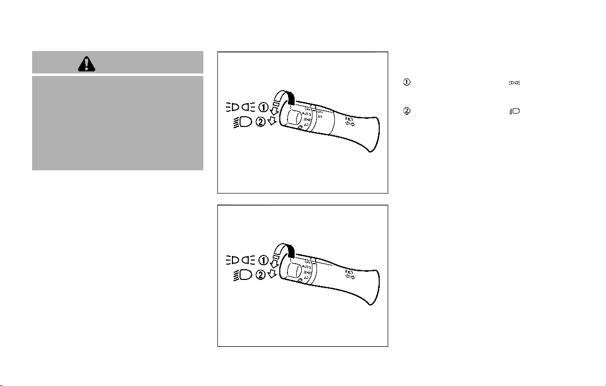
CAUTION
. When operating the deicer con-
tinuously, be sure to start the
engine. Otherwise, it may cause
the battery to discharge.
. When cleaning the inner side of
the window, be careful not to
scratch or damage the electrical
conductors on the surface of the
window.
SIC3668
Type A (if so equipped)
JVI1505X
Type B (if so equipped)
HEADLIGHT SWITCH
Lighting
Turn the switch to the position:
The front parking, side marker, tail, license
plate and instrument lights will come on.
Turn the switch to the position:
Headlights will come on and all the other
lights remain on.
Instruments and controls 2-37
HEADLIGHT AND TURN SIGNAL SWITCH
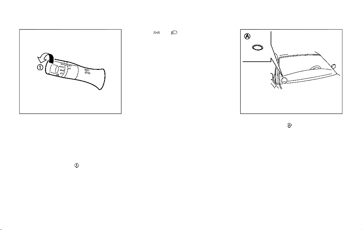
2-38 Instruments and controls
SIC3669
Intelligent Auto Headlight system
The Intelligent Auto Headlight system
allows the headlights to be set so they
turn on and off automatically.
To set the Intelligent Auto Headlight
system:
1. Make sure the headlight switch is in
the AUTO position
.
2. Place the ignition switch in the ON
position.
3. The Intelligent Auto Headlight system
automatically turns the headlights on
and off.
To turn the Intelligent Auto Headlight
system off, turn the headlight switch to
the OFF,
or position.
The Intelligent Auto Headlight system can
turn on the headlights automatically
when it is dark and turn off the headlights
when it is light.
The headlights will also be turned on
automatically at twilight or in rainy
weather (when the windshield wiper is
operated continuously).
If the ignition switch is placed in the OFF
position and one of the doors is opened
and this condition is continued, the head-
lights remain on for 5 minutes.
Automatic headlights off delay:
You can keep the headlights on for up to
180 seconds after you place the ignition
switch in the OFF position and open any
door then close all the doors.
You can adjust the period of the auto-
matic headlights off delay from 0 seconds
(OFF) to 180 seconds. The factory default
setting is 45 seconds.
For automatic headlights off delay
setting, see NissanConnect® Owner’s
Manual.
SIC3784A
Be sure not to put anything on top of
the photo sensor
located on the top
of the instrument panel. The photo
sensor controls the Intelligent Auto
Headlight system; if it is covered, the
photo sensor reacts as if it is dark and
the headlights will illuminate.
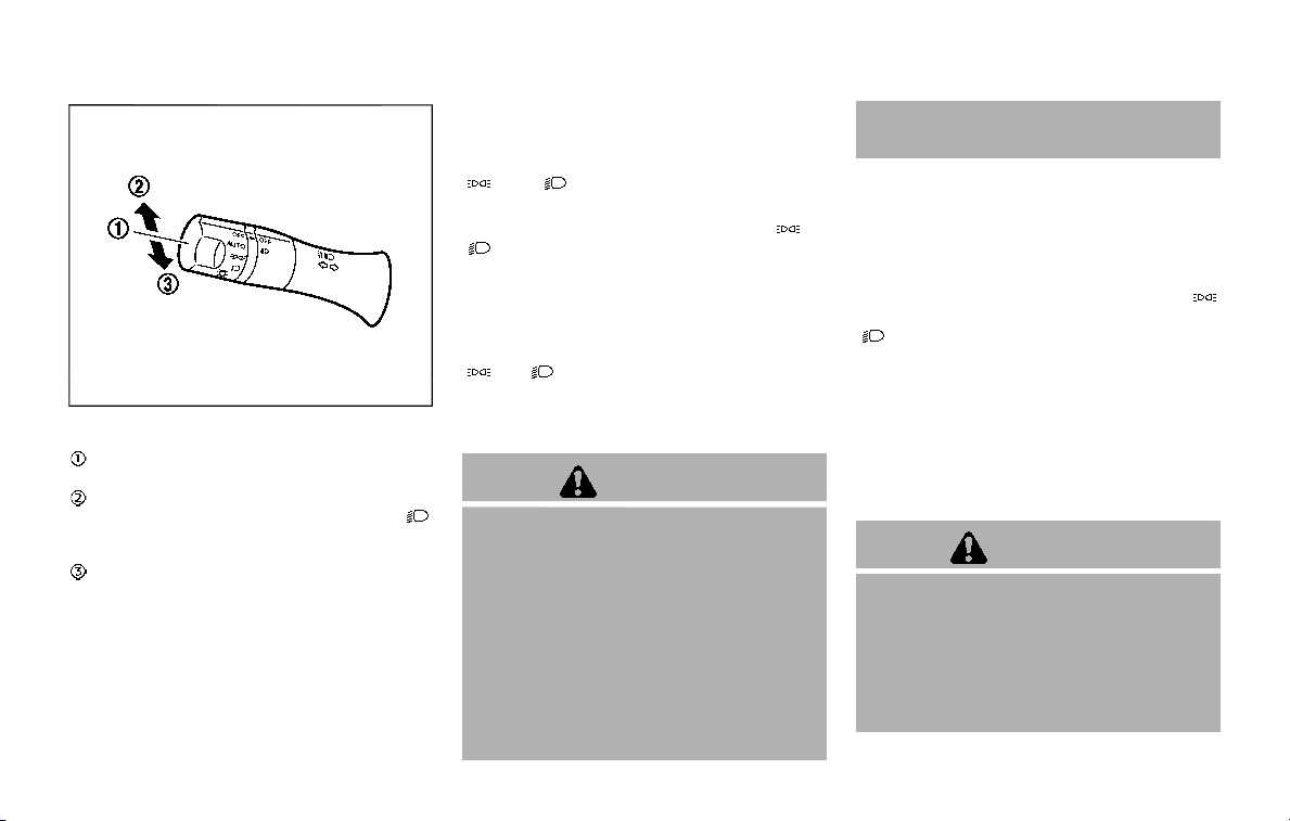
SIC3670
Headlight beam select
To select the low beam, put the lever in
the neutral position as shown.
To select the high beam, push the lever
forward while the switch is in the
position. Pull it back to select the low
beam.
Pulling the lever toward you will flash the
headlight high beam even when the
headlight switch is in the OFF position.
Battery saver system
A chime will sound when the driver side
door is opened with the light switch in the
or position and the ignition
switch in the OFF or LOCK position.
When the headlight switch is in the
or
position while the ignition switch is in
the ON position, the lights will automati-
cally turn off after a period of time when
the ignition switch has been pushed to
the OFF position.
When the headlight switch remains in the
or position after the lights auto-
matically turn off, the lights will turn on
when the ignition switch is pushed to the
ON position.
CAUTION
. When you turn on the headlight
switch again after the lights auto-
matically turn off, the lights will
not turn off automatically. Be
sure to turn the light switch to
the OFF position when you leave
the vehicle for extended periods
of time, otherwise the battery will
be discharged.
. Never leave the light switch on
when the engine is not running
for extended periods of time even
if the headlights turn off auto-
matically.
Daytime running light system
The daytime running lights automatically
illuminate when the engine is started with
the parking brake released. The daytime
running lights operate with the headlight
switch in the OFF position or in the
position. Turn the headlight switch to the
position for full illumination when
driving at night.
If the parking brake is applied before the
engine is started, the daytime running
lights do not illuminate. The daytime
running lights illuminate once the parking
brake is released. The daytime running
lights will remain on until the ignition
switch is pushed to the OFF position.
WARNING
When the daytime running light sys-
tem is active, tail lights on your
vehicle are not on. It is necessary at
dusk to turn on your headlights.
Failure to do so could cause an
accident injuring yourself and
others.
Instruments and controls 2-39
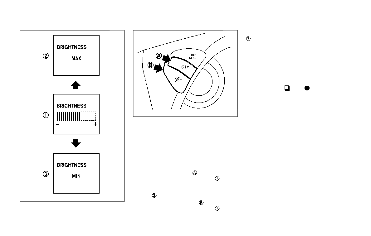
2-40 Instruments and controls
SIC3270
SIC4378
INSTRUMENT BRIGHTNESS CON-
TROL
The instrument brightness control switch
can be operated when the ignition switch
is in the ON position. When the switch is
operated, the vehicle information display
switches to the brightness adjustment
mode.
Push the upper switch
to brighten the
instrument panel lights. The bar
moves
to the + side. When reaching the max-
imum brightness, “MAX” appears on the
display
.
Push the lower switch
to dim the
instrument panel lights. The bar
moves
to the − side. When reaching the minimum
brightness, “MIN” appears on the display
. However, “MIN” does not appear during
the nighttime.
The vehicle information display returns to
the normal display under the following
conditions:
. when the instrument brightness con-
trol switch is not operated for more
than 5 seconds.
. when the
or switch on the
right side of the combination meter
panel is pushed.
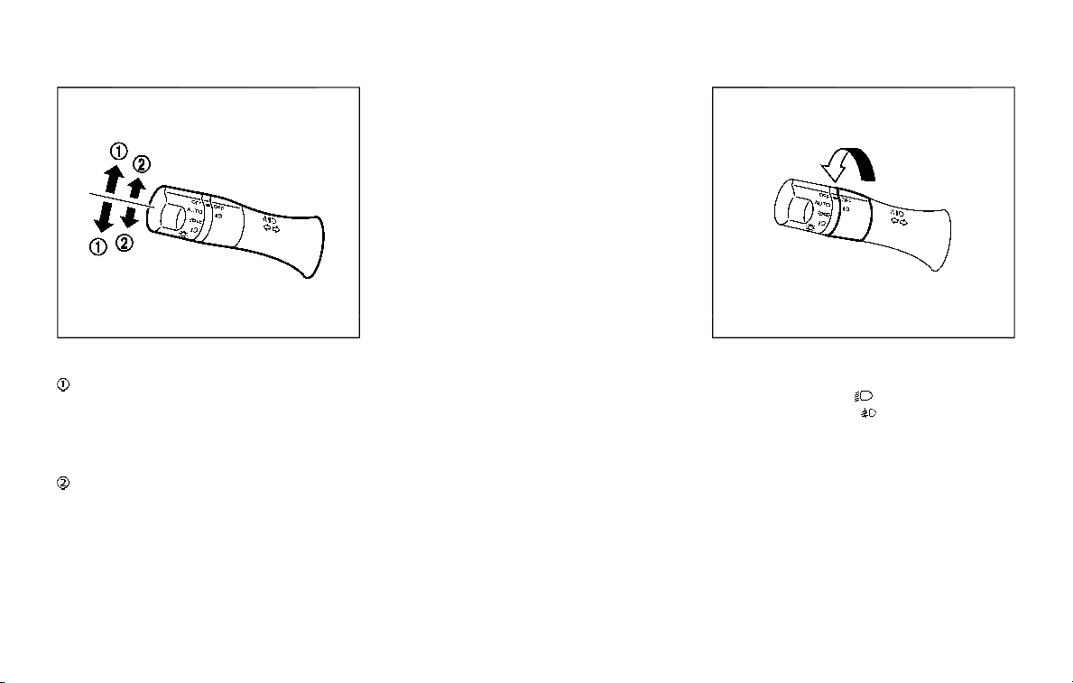
SIC3671
TURN SIGNAL SWITCH
Turn signal
Move the lever up or down to signal the
turning direction. When the turn is com-
pleted, the turn signals cancel automati-
cally.
Lane change signal
. Move the lever up or down until the
turn signal begins to flash, but the
lever does not latch, to signal a lane
change. Hold the lever until the lane
change is completed.
. Move the lever up or down until the
turn signal begins to flash, but the
lever does not latch, and release the
lever. The turn signal will automati-
cally flash three times.
Choose the appropriate method to signal
a lane change based on road and traffic
conditions.
SIC3672
FOG LIGHT SWITCH (if so equipped)
To turn the fog lights on, turn the head-
light switch to the
position, then turn
the switch to the
position. To turn
them off, turn the switch to the OFF
position.
The headlights must be on with the low
beams selected for the fog lights to
operate. The fog lights automatically turn
off when the high beam headlights are
selected.
Instruments and controls 2-41
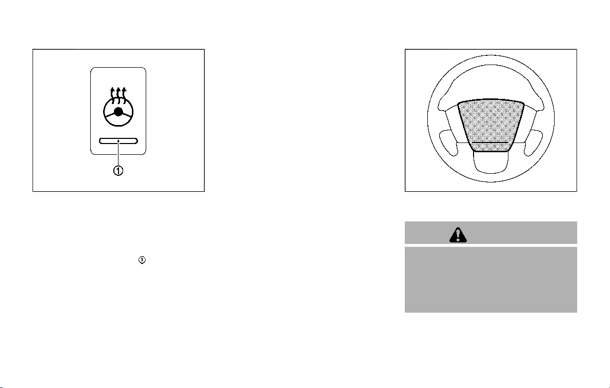
2-42 Instruments and controls
SIC4401
The heated steering wheel system is
designed to operate only when the sur-
face temperature of the steering wheel is
below 68°F (20°C).
Push the heated steering wheel switch to
warm the steering wheel after the engine
starts. The indicator light
on the switch
will illuminate.
If the surface temperature of the steering
wheel is below 68°F (20°C), the system will
heat the steering wheel and cycle off and
on to maintain a temperature above 68°F
(20°C). The indicator light will remain on
as long as the system is on.
Push the switch again to turn the heated
steering wheel system off manually. The
indicator light will turn off.
NOTE:
If the surface temperature of the steer-
ing wheel is above 68°F (20°C) when the
switch is turned on, the system will not
heat the steering wheel. This is not a
malfunction.
SIC4444
To sound the horn, push the center pad
area of the steering wheel.
WARNING
Do not disassemble the horn. Doing
so could affect proper operation of
the supplemental front air bag sys-
tem. Tampering with the supple-
mental front air bag system may
result in serious personal injury.
HEATED STEERING WHEEL (if so equipped)
HORN
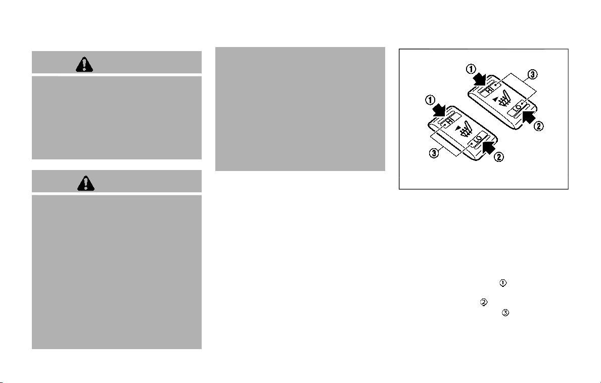
WARNING
Do not use or allow occupants to use
the seat heater if you or the occu-
pants cannot monitor elevated seat
temperatures or have an inability to
feel pain in body parts that contact
the seat. Use of the seat heater by
such people could result in serious
injury.
CAUTION
. The battery could run down if the
seat heater is operated while the
engine is not running.
. Do not use the seat heater for
extended periods or when no one
is using the seat.
. Do not put anything on the seat
which insulates heat, such as a
blanket, cushion, seat cover, etc.
Otherwise, the seat may become
overheated.
. Do not place anything hard or
heavy on the seat or pierce it with
a pin or similar object. This may
result in damage to the heater.
. Any liquid spilled on the heated
seat should be removed immedi-
ately with a dry cloth.
. When cleaning the seat, never use
gasoline, thinner, or any similar
materials.
. If any malfunctions are found or
the heated seat does not operate,
turn the switch off and have the
system checked. It is recom-
mended you visit a NISSAN dealer
for this service.
SIC2770
FRONT (if so equipped)
The front seats can be warmed by built-in
heaters. The switches located on the
instrument panel can be operated inde-
pendently of each other.
1. Start the engine.
2. Select heat range.
.
For high heat, push the HI (High)
side of the switch
.
.
For low heat, push the LO (Low) side
of the switch
.
.
The indicator light will illuminate
when the heater is on.
3. To turn off the heater, return the
switch to the level position. Make sure
Instruments and controls 2-43
HEATED SEATS
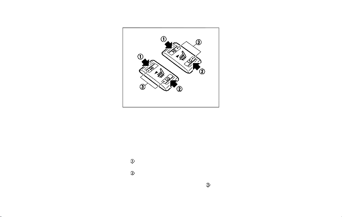
2-44 Instruments and controls
the indicator light turns off.
SIC2770
REAR (if so equipped)
The 2nd row outboard seats are warmed
by built-in heaters. The switches located
on the back side of the center console
can be operated independently of each
other.
1. Start the engine.
2. Select heat range.
For high heat, push the HI (High)
side of the switch.
For low heat, push the LO (Low) side
of the switch.
The indicator light in the switch
will
illuminate when the heater is on.
3. To turn off the heater, return the
switch to the level position. Make sure
the indicator light turns off.
The heater is controlled by a thermo-
stat, automatically turning the heater
on and off. The indicator light will
remain on as long as the switch is on.
When the vehicle’s interior is warmed,
or before you leave the vehicle, be
sure to turn off the switch.
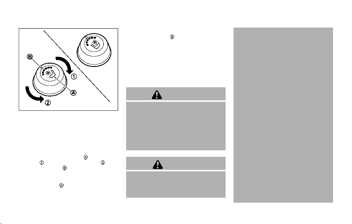
SIC4334
The climate controlled seat warms up or
cools down the front seats by built-in
heaters or blowing cool air from the
surface of the seat. The switches located
on the instrument panel can be operated
independently of each other.
1. Start the engine.
2. Turn the control knob
to the heat
side
or to the cool side . The
indicator light
on the control knob
will illuminate.
3. Adjust the temperature using the
control knob
.
4. When the vehicle’s interior is warmed
or cooled, and/or before you leave the
vehicle, be sure to turn the control
knob to the OFF position (center). The
indicator light
on the control knob
goes off at the OFF position.
The climate controlled seat has air
filters. If the climate controlled seat is
not functioning properly, it may indi-
cate the air filters may be clogged. To
check the air filters for the climate
controlled seat, it is recommended
you visit a NISSAN dealer.
WARNING
Do not use or allow occupants to use
the climate controlled seats if you or
the occupants cannot monitor seat
temperatures or have an inability to
feel pain in those body parts in
contact with the seat. Use of the
climate controlled seats by such
people could result in serious injury.
CAUTION
. The battery could run down if the
climate controlled seat is oper-
ated while the engine is not run-
ning.
. Do not use the climate controlled
seat for extended periods or
when no one is using the seat.
. Do not put anything on the seat
which insulates heat, such as a
blanket, cushion, seat cover, etc.
Otherwise, the seat may become
overheated.
. Do not place anything hard or
heavy on the seat or pierce it with
a pin or similar object. This may
result in damage to the climate
controlled seat.
. Any liquid spilled on the seat
should be removed immediately
with a dry cloth.
. The climate controlled seat has
an air filter. Do not operate cli-
mate controlled seat without an
air filter. This may result in da-
mage to the system.
. When cleaning the seat, never use
gasoline, thinner, or any similar
materials.
. If any malfunctions are found or
the climate controlled seat does
not operate, turn the switch off
and have the system checked. It
is recommended you visit a
NISSAN dealer for this service.
Instruments and controls 2-45
CLIMATE CONTROLLED SEATS (if
so equipped)
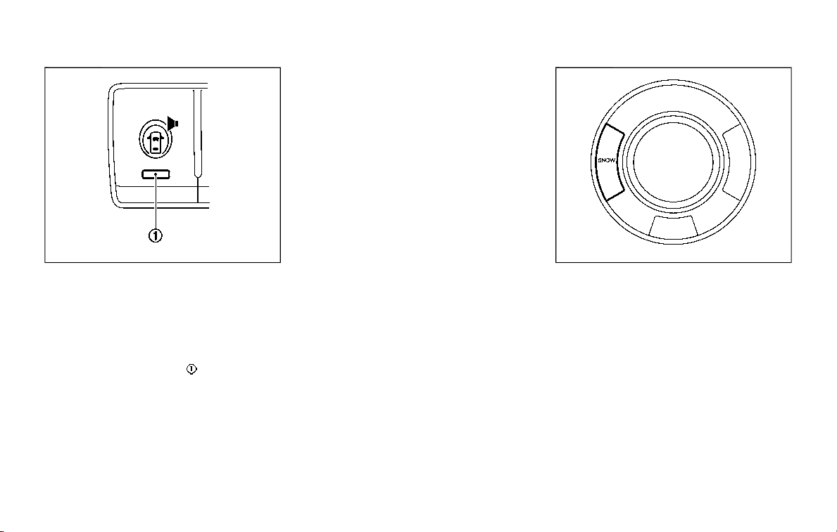
2-46 Instruments and controls
SSD0956
The warning systems switch is used to
turn on and off the warning systems
(Lane Departure Warning (LDW) and Blind
Spot Warning (BSW) systems) that are
activated using the settings menu on
the center display.
When the warning systems switch is
turned off, the indicator
on the switch
is off. The indicator will also be off if all of
the warning systems are deactivated
using the settings menu.
The LDW system will sound a warning
chime and blink the Lane Departure
Warning (LDW) indicator light (orange) to
alert the driver if the vehicle is traveling
close to either the left or the right of a
traveling lane with detectable lane mar-
kers. (See “Lane Departure Warning
(LDW)/Intelligent Lane Intervention (I-LI)”
(P.5-23).)
The BSW system will turn on the side
indicator lights, located next to the out-
side mirrors, if the radar sensors detect a
vehicle in the detection zone. If the turn
signal is activated in the direction of the
detected vehicle, a chime sounds twice
and the side indicator light will flash. (See
“Blind Spot Warning (BSW)” (P.5-32).)
SIC4454
For driving or starting the vehicle on
snowy roads or slippery areas, push on
the SNOW mode switch. The SNOW mode
indicator light will illuminate. When the
SNOW mode is activated, engine output is
controlled to avoid wheel spin.
Push off the SNOW mode for normal
driving.
WARNING SYSTEMS SWITCH (if so
equipped)
SNOW MODE SWITCH

SIC4474
TOW MODE should be used when pulling
a heavy trailer or hauling a heavy load.
Driving the vehicle in TOW MODE with no
trailer/load or light trailer/light load will
not cause any damage. However, fuel
economy may be reduced, and the trans-
mission/engine driving characteristics
may feel unusual.
Push the TOW MODE switch to activate
TOW MODE. The indicator light on the
TOW MODE switch illuminates when TOW
MODE is selected. Push the TOW MODE
switch again to turn TOW MODE OFF.
TOW MODE is automatically canceled
when the ignition switch is placed in the
OFF position.
SIC4455
The vehicle should be driven with the
Vehicle Dynamic Control (VDC) system on
for most driving conditions.
If the vehicle is stuck in mud or snow, the
VDC system reduces the engine output to
reduce wheel spin. The engine speed will
be reduced even if the accelerator is
depressed to the floor. If maximum en-
gine power is needed to free a stuck
vehicle, turn the VDC system off.
To turn off the VDC system, push the VDC
OFF switch. The
indicator will illumi-
nate.
Push the VDC OFF switch again or restart
the engine to turn on the system. (See
“Vehicle Dynamic Control (VDC) system”
(P.5-133).)
Instruments and controls 2-47
TOW MODE SWITCH
VEHICLE DYNAMIC CONTROL (VDC)
OFF SWITCH
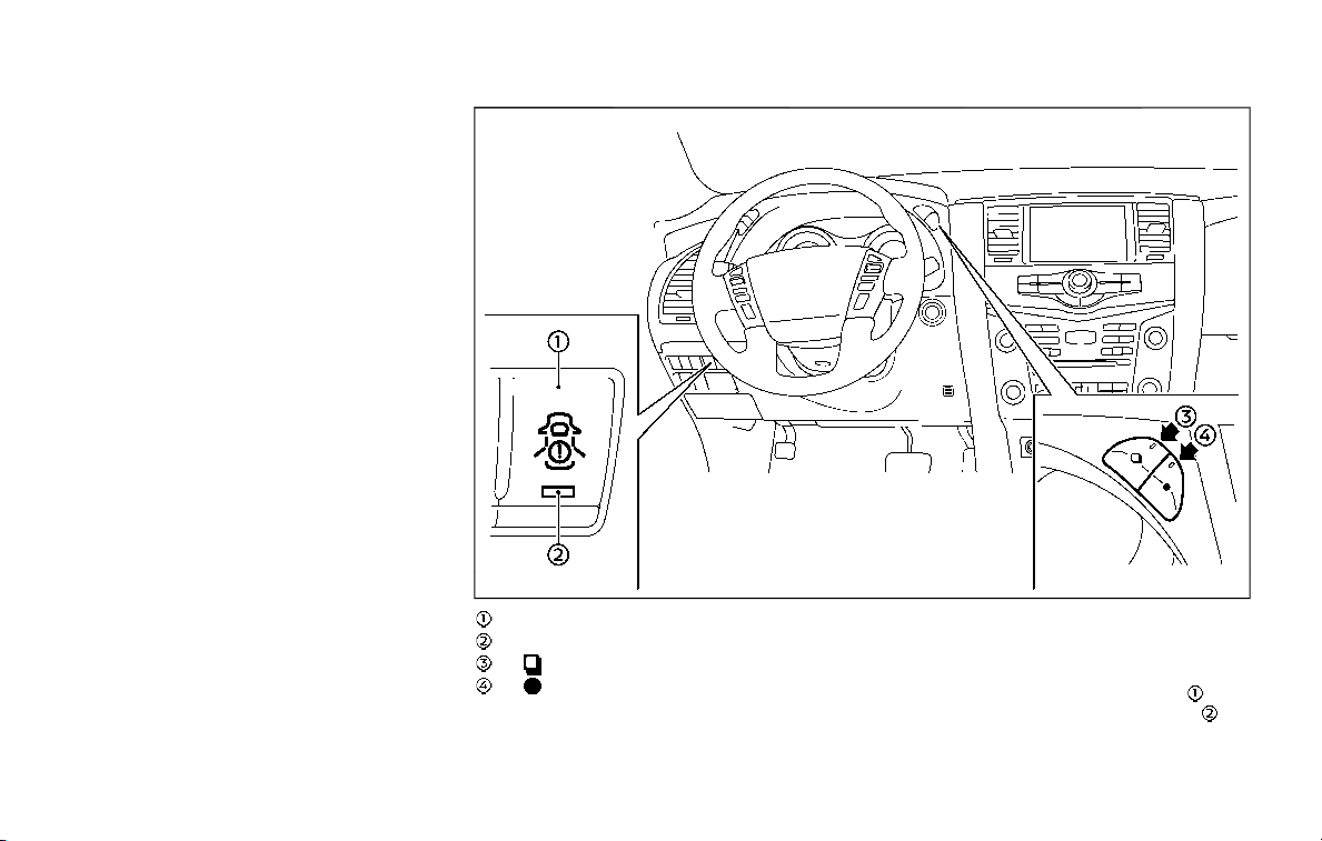
2-48 Instruments and controls
The rear door alert system functions
under certain conditions to indicate there
may be an object or passenger in the rear
seat(s). Check the seat(s) before exiting
the vehicle. The rear door alert system is
initially disabled. The driver can enable
the system using the rear door alert
switch. (See “Turning the rear door alert
system ON/OFF” (P.2-48).)
JVP0649X
Rear door alert switch
Rear door alert switch indicator light
switch
switch
TURNING THE REAR DOOR ALERT
SYSTEM ON/OFF
To turn on the rear door alert system,
push the rear door alert switch
. The
rear door alert switch indicator light
will
illuminate.
To turn off the system, push the rear door
REAR DOOR ALERT
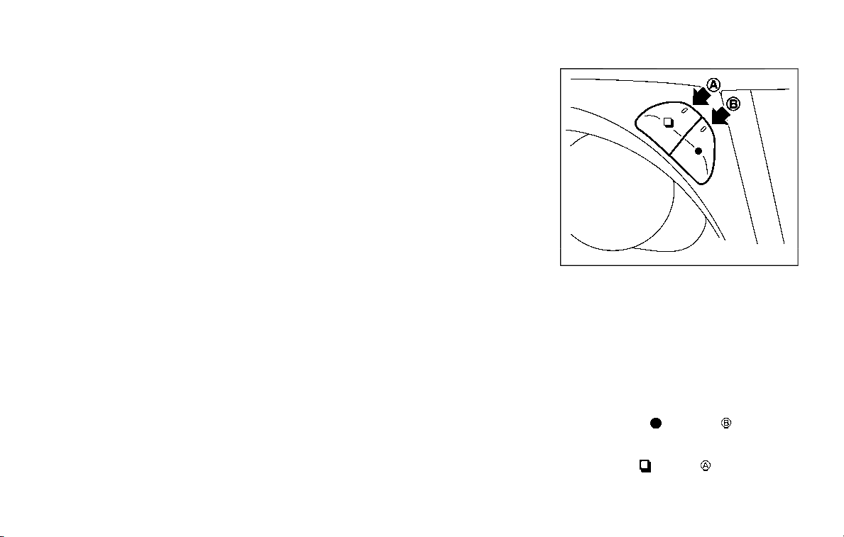
alert switch again. The rear door alert
switch indicator light will go off.
When the system is turned ON:
. The system is activated when a rear
door is opened and closed within 10
minutes of the vehicle being driven.
For additional information, refer to
“System operation” (P.2-49).
. If a rear door is opened and closed but
the vehicle is not driven within ap-
proximately 10 minutes, the system
will not be activated. A rear door must
be opened and closed and the vehicle
driven within 10 minutes for the sys-
tem to be activated.
NOTE:
. When turning on or off the system,
the system will retain current set-
tings even if the engine is restarted.
. If the battery terminal is discon-
nected and connected after the sys-
tem is turned on, the system will be
turned off and initialized. To use the
rear door alert system after the
battery terminal is disconnected
and connected for servicing by the
customer or a NISSAN dealer, push
the rear door alert switch to turn on
the system.
SYSTEM OPERATION
When the rear door alert system is
activated and the driver exits the vehicle
after arriving at a destination:
. When the driver places the vehicle in
the P (Park) position, a message ap-
pears in the vehicle information dis-
play for a driver to select “DISMISS
MESSAGE” or “DISABLE ALERT” if de-
sired.
. With the system enabled, when the
driver exits the vehicle, an audible alert
(horn sound) will occur unless a rear
door is opened and closed within a
short time to deactivate the alert.
. If the doors are locked before the alert
is deactivated by opening a rear door,
the horn will sound.
. If the system is activated but the
liftgate is opened before opening a
rear door, the audible horn alert will be
delayed until after the liftgate is
closed.
. If the audible horn alert occurs, a
message will also appear in the vehi-
cle information display that states,
“CHECK BACK SEAT FOR All ARTICLES”.
SIC4420
HOW TO TEMPORARILY DISABLE
THE REAR DOOR ALERT SYSTEM
Perform the following steps to tempora-
rily disable the rear door alert system.
1. When the driver places the vehicle in
the P (Park) position, a message ap-
pears in the vehicle information dis-
play for a driver to select “DISMISS
MESSAGE” or “DISABLE ALERT” if de-
sired.
2. Push the
switch to toggle
between “DISMISS MESSAGE” and “DIS-
ABLE ALERT”.
3. Push the
switch to enter.
Instruments and controls 2-49
2-50 Instruments and controls
.
Using switch , a driver can
select “DISMISS MESSAGE” to clear
the display for a period of time. If no
selection is made, this message
automatically turns off after a per-
iod of time.
.
Using switch , a driver can
select “DISABLE ALERT” to disable
the horn alert for the remainder of
the current trip.
WARNING
. There may be times when there is
an object or passenger in the rear
seat(s) but the audible alert does
not sound. For example, this may
occur if rear seat passengers
enter or exit the vehicle during a
trip.
. The system does not directly
detect objects or passengers in
the rear seat(s). Instead, it can
detect when a rear door is
opened and closed, indicating
that there may be something in
the rear seat(s).
NOTE:
There may be times when the horn
sounds but there are no objects or
passengers in the rear seat(s).
CAUTION
. Use power outlet with the engine
running to avoid discharging the
vehicle battery.
. Avoid using power outlet when
the air conditioner, headlights or
rear window defroster is on.
. Before inserting or disconnecting
a plug, be sure the electrical
accessory being used is turned
OFF.
. When not in use, be sure to close
the cap. Do not allow water or any
liquid to contact the outlet.
POWER OUTLET
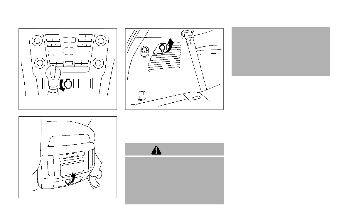
SIC4389
Instrument panel
SIC4456
Back side of front console
SIC4391
Luggage room
Type A (if so equipped)
The power outlet is used for powering
electrical accessories such as cellular
telephones.
CAUTION
. The outlet and plug may be hot
during or immediately after use.
. Do not use with accessories that
exceed a combined power draw
of 12 volts, 120W (10A) for all the
power outlets. Do not use double
adapters or more than one elec-
trical accessory.
. This power outlet is not designed
for use with a cigarette lighter
unit.
. Push the plug in as far as it will
go. If good contact is not made,
the plug may overheat or the
internal temperature fuse may
blow.
Instruments and controls 2-51

2-52 Instruments and controls
SIC2648
Main switch
Type B (if so equipped)
The power outlet (plug type) is located on
the back side of the front console. It can
operate when the ignition switch in the
ON position and the main switch (located
in the console box) is ON.
The specification of this power outlet is
for use of a 120 volt, 150W (1.25A) power
draw.
To turn on or off the power supply to the
outlet, push the ON
or OFF side of the
main switch. When the switch is turned to
the ON position, the indicator light
will
illuminate.
JVI1638X
Power outlet
Pull up the cover and plug in.
After using the power outlet, be sure to
turn off the main switch.
CAUTION
. Do not use with accessories that
exceed a 120 volt, 150W (1.25A)
power draw.
. Use this power outlet with the
engine running. (If the engine is
stopped, this could result in a
discharged battery.)
JVI1604X
USB (Universal Serial Bus) CHAR-
GING CONNECTOR
The USB connector can be used only
for charging an external device.
Open the cover to access the USB con-
nector.
Connect a USB device into the connector.
Charging will start automatically (max-
imum output up to 5 volt, 12W, 2.4A).
The external device will be charged con-
tinuously while the ignition switch is in
the ACC or ON position.
Some mobile devices cannot be charged
depending on their specifications.
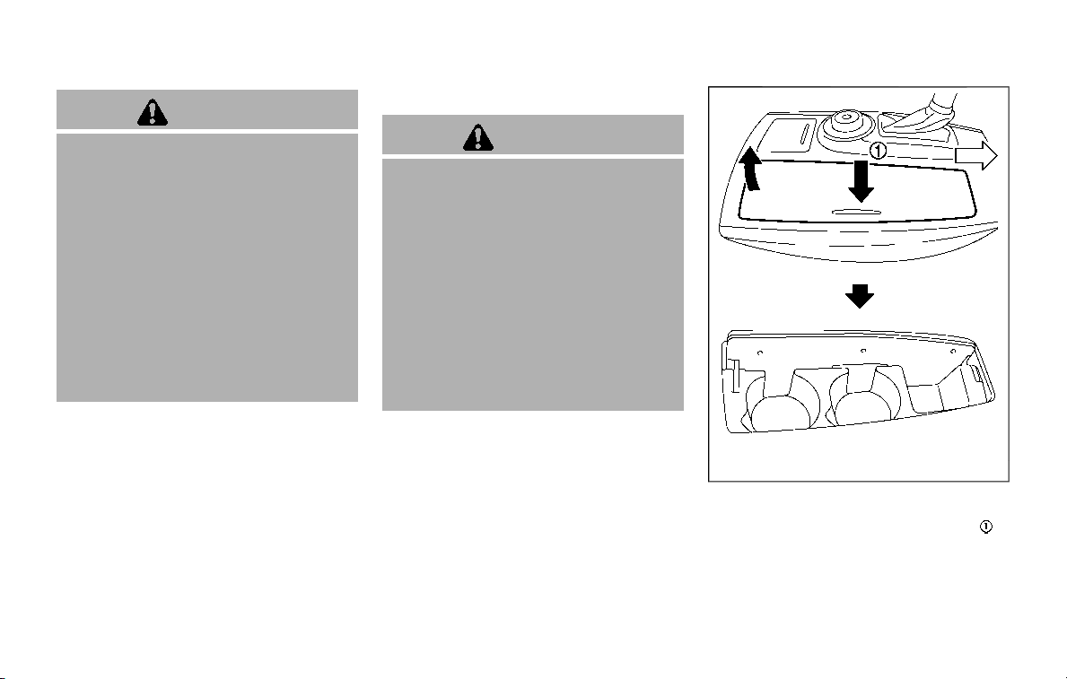
CAUTION
. Do not force a USB device into the
connector. Inserting the USB de-
vice tilted or up-side-down into
the connector may damage the
connector. Make sure that the
USB device is connected correctly
into the connector.
. Do not use a reversible USB cable.
Using the reversible USB cable
may damage the connector.
. Do not grab the USB connector
cover when pulling the USB de-
vice out of the connector. This
could damage the connector and
the cover.
CUP HOLDERS
CAUTION
. Avoid abrupt starting and braking
when the cup holder is being
used to prevent spilling the drink.
If the liquid is hot, it can scald you
or your passenger.
. Use only soft cups in the cup
holder. Hard objects can injure
you in an accident.
. Do not recline the rear seatback
when you use the cup holders on
the rear armrest. Doing so may
cause the beverages to spill over,
and if they are hot, they may
scald the passengers.
JVI1688X
Front
To open the cup holder, push the lid .
To close, lower the cup holder lid and
push it down lightly.
The cup holder is not designed to store
personal items.
Instruments and controls 2-53
STORAGE
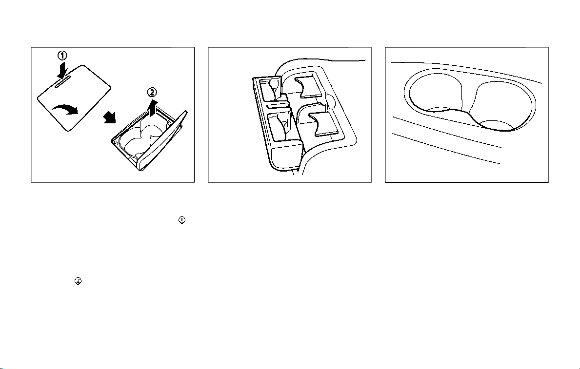
2-54 Instruments and controls
SIC3118
2nd row seat
Type A (if so equipped):
To open the cup holder, push the lid
.
The flap will be folded down when insert-
ing a large container.
To close, lower the cup holder lid and
push it down lightly.
To clean the front cup holder, pull up the
inside tray
and remove it.
The cup holder is not designed to store
personal items.
SIC2915
Type B (if so equipped):
To open the cup holder, pull the lid.
SIC4419
3rd row seat
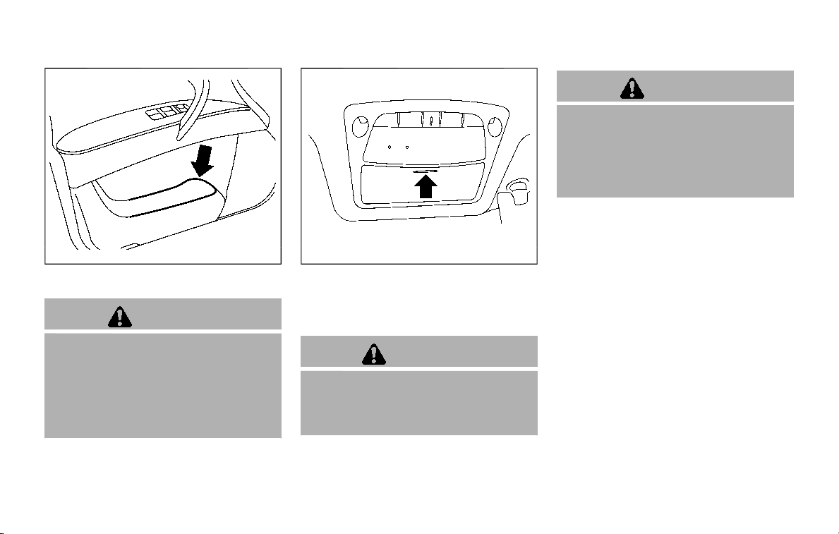
SIC4501
Soft bottle holder
CAUTION
. Do not use bottle holder for any
other objects that could be
thrown about in the vehicle and
possibly injure people during
sudden braking or an accident.
. Do not use bottle holder for open
liquid containers.
JVI0619X
SUNGLASSES HOLDER
To open the sunglasses holder, push and
release. Only store one pair of sunglasses
in the holder.
WARNING
Keep the sunglasses holder closed
while driving to avoid obstructing
the driver’s view and to help prevent
an accident.
CAUTION
. Do not use for anything other
than glasses.
. Do not leave glasses in the sun-
glasses holder while parking in
direct sunlight. The heat may
damage the glasses.
Instruments and controls 2-55
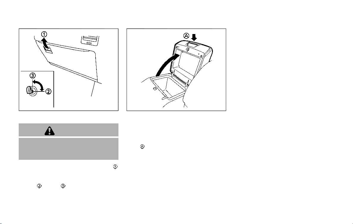
2-56 Instruments and controls
SIC4393
GLOVE BOX
WARNING
Keep glove box lid closed while driv-
ing to help prevent injury in an
accident or a sudden stop.
To open the glove box, pull the handle
.
To close, push the lid in until the lock
latches.
To lock
/unlock the glove box, use the
mechanical key. For the mechanical key
usage, see “Keys” (P.3-2).
JVI1711X
CONSOLE BOX
Front
Type A (if so equipped):
To open the console box lid, push up the
knob
and pull up the lid.
To close, push the lid down until the lock
latches.
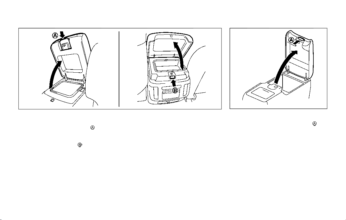
JVI1509X
Type B (if so equipped):
To open the console box lid from the
front seat, push up the knob
and pull
up the lid.
To open the console box lid from the 2nd
row seat, push the knob
.
To close, push the lid down until the lock
latches.
SIC4422
Rear (if so equipped)
To open the lid, push the knob up and
pull up the lid.
To close, push the lid down until the lock
latches.
Instruments and controls 2-57
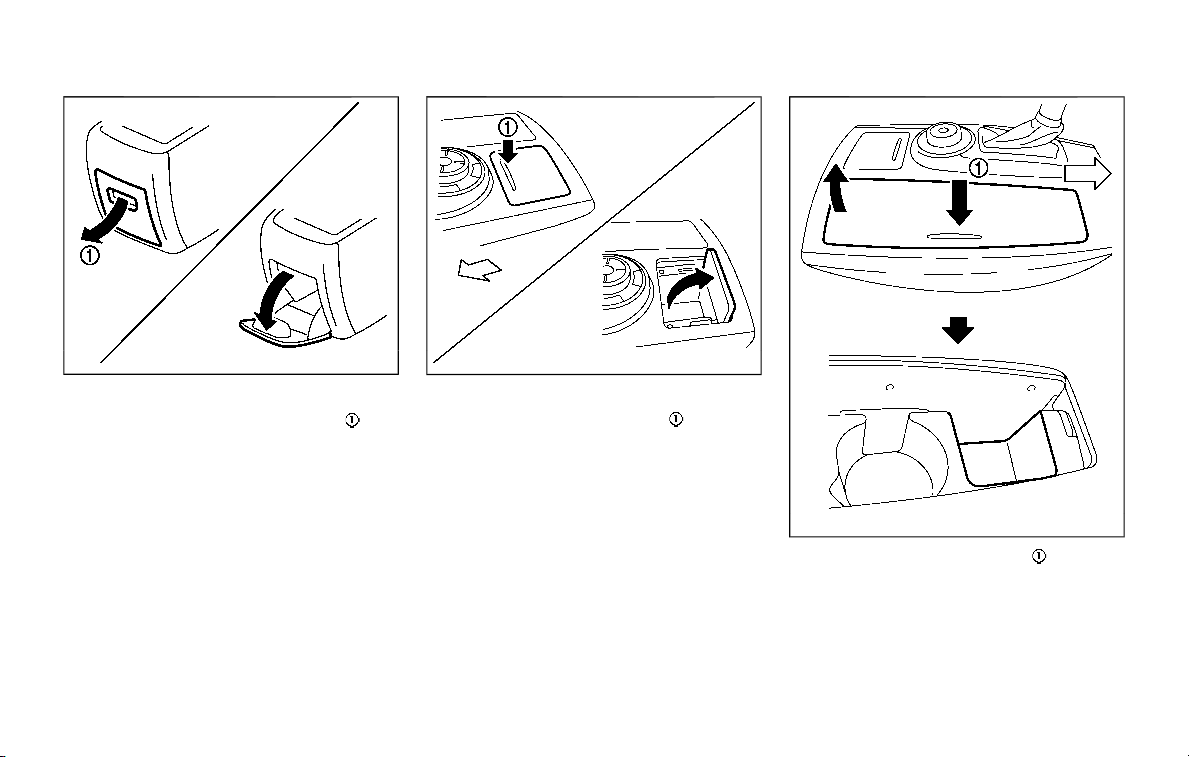
2-58 Instruments and controls
SIC4423
Pocket:
To open the pocket, pull the knob
.
To close, push the lid until the lock
latches.
JVI1687X
TRAY
To open the tray, push the lid . To close,
push the lid down.
JVI1690X
To open the tray, push the lid . To close,
push the lid down.
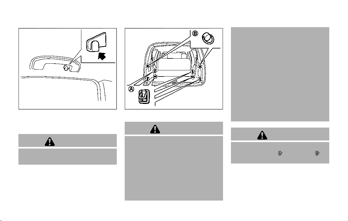
SIC3505
COAT HOOKS
The coat hooks are equipped at the rear
assist grips.
CAUTION
Do not place items which are more
than 2 lb (1 kg) on the hook.
SIC4446
LUGGAGE HOOKS
WARNING
. Always make sure that the cargo
is properly secured. Use the sui-
table ropes and hooks.
. Unsecured cargo can become
dangerous in an accident or sud-
den stop.
. Never allow anyone to ride in the
luggage area. It is extremely dan-
gerous to ride in a cargo area
inside of a vehicle. In a collision,
people riding in these areas are
more likely to be seriously injured
or killed.
. Do not allow people to ride in any
area of your vehicle that is not
equipped with seats and seat
belts.
. The child restraint top tether
strap may be damaged by con-
tact with items in the cargo area.
Secure any items in the cargo
area. Your child could be seriously
injured or killed in a collision if the
top tether strap is damaged.
. Be sure everyone in your vehicle
is in a seat and using a seat belt
properly.
CAUTION
Do not apply a total load of more
than 22 lb (10 kg)
or 7 lb (3 kg) to
the hook.
Instruments and controls 2-59
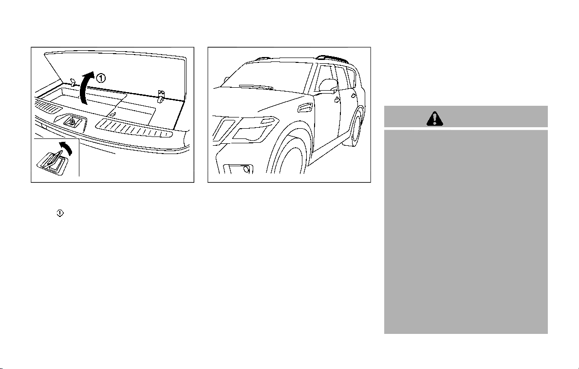
2-60 Instruments and controls
JVI1204X
CARGO FLOOR BOX
Push the handle to open the cargo floor
board
.
JVI1515X
ROOF RACK
Do not apply any load directly to the roof
side rails. Cross bars must be installed
before applying load/cargo/luggage to
the roof of the vehicle. Genuine NISSAN
accessory cross bars are available
through a NISSAN dealer. It is recom-
mended that you visit a NISSAN dealer for
additional information.
The service load capacity for the roof side
rails is 221 lb (100 kg), however do not
exceed the accessory cross bars load
capacity.
Be careful that your vehicle does not
exceed the Gross Vehicle Weight Rating
(GVWR) or its Gross Axle Weight Rating
(GAWR front and rear). The GVWR and
GAWR are located on the F.M.V.S.S. or C.V.
M.S.S. certification label (located on the
driver’s door pillar). For additional infor-
mation regarding GVWR and GAWR, refer
to “Vehicle loading information” (P.10-13).
WARNING
. Always install the cross bars onto
the roof side rails before loading
cargo of any kind. Loading cargo
directly onto the roof side rails or
the vehicle’s roof may cause ve-
hicle damage.
. Drive extra carefully when the
vehicle is loaded at or near the
cargo carrying capacity, espe-
cially if the significant portion of
that load is carried on the roof
rack.
. Heavy loading of the roof rack
has the potential to affect the
vehicle stability and handling
during sudden or unusual hand-
ling maneuvers.
. Roof rack load should be evenly
distributed.
. Do not exceed maximum roof
rack load weight capacity.
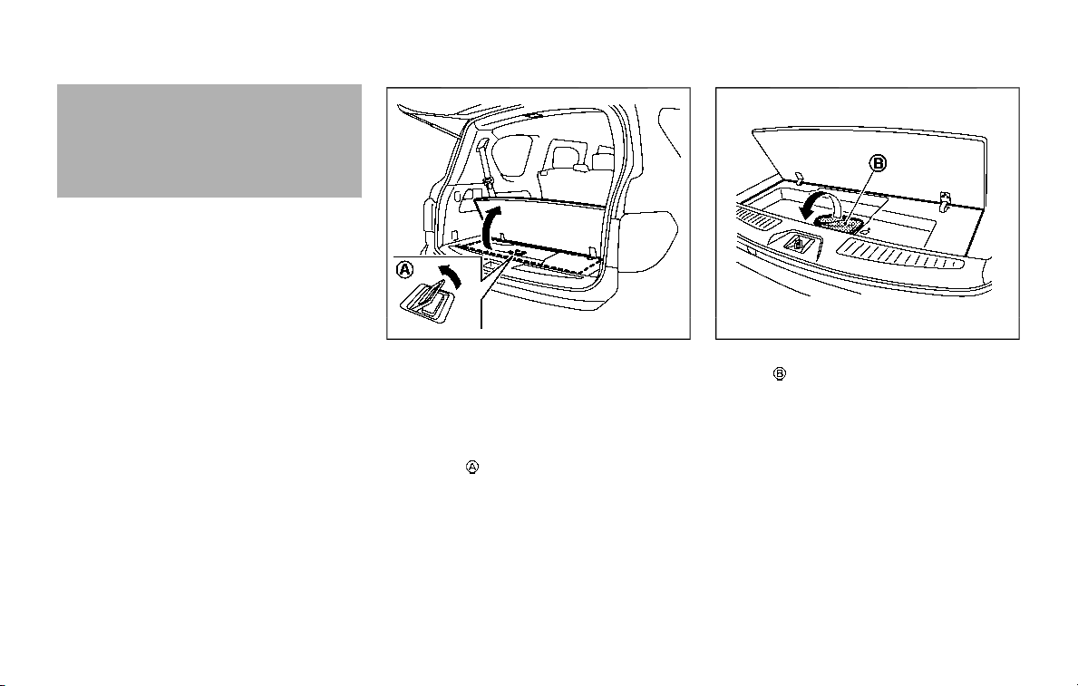
. Properly secure all cargo with
ropes or straps to help prevent it
from sliding or shifting. In a sud-
den stop or collision, unsecured
cargo could cause personal in-
jury.
JVE0219X
REAR BUMPER COVER
The rear bumper cover helps prevent the
rear bumper from being scratched or
damaged when loading or unloading a
cargo.
1. Open the cargo floor board using the
handle
.
JVI1516X
2. Take the rear bumper cover from the
bag
stored in the cargo floor box.
Instruments and controls 2-61
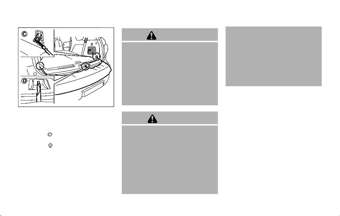
2-62 Instruments and controls
JVI1517X
3. Install the rear bumper cover.
.
Place the cover over the surface
with the tag facing down.
.
Attach the hooks to the luggage
hooks
.
.
Secure the strap to the liftgate
striker
.
4. Cover the upper part of the rear
bumper as shown.
After loading or unloading the cargo, be
sure to remove the rear bumper cover
and store it in the storage place.
WARNING
. Never install the rear bumper
cover while the engine is running.
The exhaust gas could heat the
rear bumper cover and this may
cause a fire.
. Never drive with the rear bumper
cover left in place. There is a risk
that the liftgate will not close
correctly, and that carbon mon-
oxide may enter the cabin caus-
ing serious injury or death.
CAUTION
. Failure to follow the instructions
below could result in damage to
the rear bumper cover.
— Do not close the liftgate with
the rear bumper cover in-
stalled.
— Do not strike or apply exces-
sive force to the rear bumper
cover.
— Keep the rear bumper cover
away from heat or fire.
— To clean the rear bumper cov-
er, use a soft cloth, dampened
with a mild solution of neutral
detergent. Never use benzine,
thinner or any similar chemi-
cal.
— Remove any solvent such as
oil or gasoline spilled on the
surface of the rear bumper
cover as soon as possible.

POWER WINDOWS
WARNING
. Make sure that all passengers
have their hands, etc. inside the
vehicle while it is in motion and
before closing the windows. Use
the window lock switch to pre-
vent unexpected use of the
power windows.
. To help avoid risk of injury or
death through unintended opera-
tion of the vehicle and or its
systems, including entrapment
in windows or inadvertent door
lock activation, do not leave chil-
dren, people who require the
assistance of others or pets un-
attended in your vehicle. Addi-
tionally, the temperature inside a
closed vehicle on a warm day can
quickly become high enough to
cause a significant risk of injury
or death to people and pets.
The power windows operate when the
ignition switch is in the ON position or for
about 45 seconds after the ignition
switch is pushed to the OFF position. If
the driver’s or front passenger’s door is
opened during this period of about 45
seconds, power to the windows is can-
celed.
SIC4352
1. Driver side window
2. Front passenger side window
3. Rear left passenger side window
4. Rear right passenger side window
5. Window lock button
Main power window switch (driver’s
side)
To open or close the window, push down
or pull up the switch and hold it. The
main switch (driver side switches) will
open or close all the windows.
Instruments and controls 2-63
WINDOWS
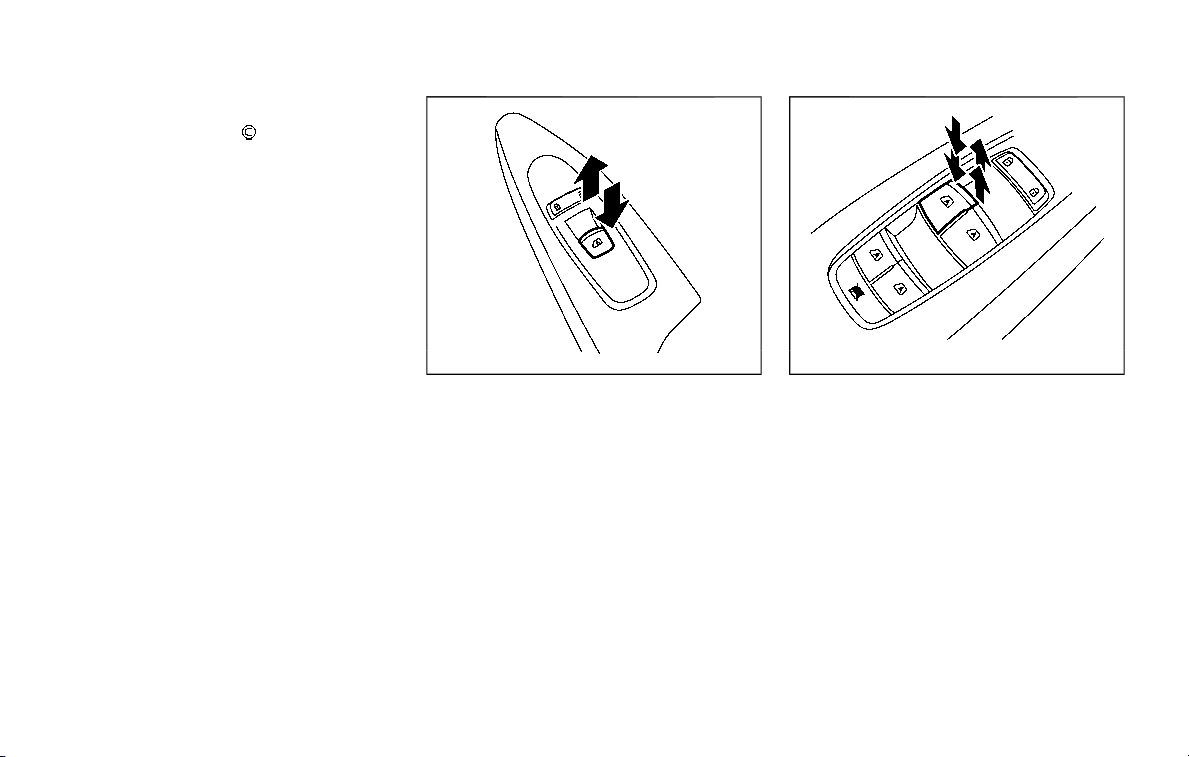
2-64 Instruments and controls
Locking passengers’ windows
When the lock button is pushed in, only
the driver side window can be opened or
closed. Push it in again to cancel.
SIC4353
Passenger side power window
switch
The passenger side switch will open or
close only the corresponding window. To
open or close the window, push down or
pull up the switch and hold it.
SIC4354
Automatic operation
To fully open or close the window, com-
pletely push down or pull up the switch
and release it; it need not be held. The
window will automatically open or close
all the way. To stop the window, just push
or lift the switch in the opposite direction.
A light push or pull on the switch will
cause the window to open or close until
the switch is released.

Auto reverse function
WARNING
There are some small distances im-
mediately before the closed position
which cannot be detected. Make sure
that all passengers have their hands,
etc., inside the vehicle before closing
the window.
If the control unit detects something
caught in the window as it is closing, the
window will be immediately lowered.
The auto reverse function can be acti-
vated when the window is closed by
automatic operation when the ignition
switch is in the ON position or for 45
seconds after the ignition switch is
pushed to the OFF position.
Depending on the environment or driv-
ing conditions, the auto reverse func-
tion may be activated if an impact or
load similar to something being caught
in the window occurs.
If the windows do not close auto-
matically
If the power window automatic function
(closing only) does not operate properly,
perform the following procedure to initi-
alize the power window system.
1. Push the ignition switch to start the
engine.
2. Close the door.
3. After starting the engine, open the
window completely by operating the
power window switch.
4. Pull the power window switch and
hold it to close the window, and then
hold the switch more than 3 seconds
after the window is closed completely.
5. Release the power window switch.
Operate the window by the automatic
function to confirm the initialization is
complete.
6. Perform steps 2 through 5 above for
other windows.
If the power window automatic function
does not operate properly after perform-
ing the procedure above, have your
vehicle checked. It is recommended you
visit a NISSAN dealer for this service.
WARNING
. In an accident you could be
thrown from the vehicle through
an open moonroof. Always use
seat belts and child restraints.
. Do not allow anyone to stand up
or extend any portion of their
body out of the moonroof open-
ing while the vehicle is in motion
or while the moonroof is closing.
CAUTION
. Remove water drops, snow, ice or
sand from the moonroof before
opening.
. Do not place any heavy object on
the moonroof or surrounding
area.
POWER MOONROOF
The moonroof only operates when the
ignition switch is in the ON position.
The moonroof is operational for about 45
seconds, even if the ignition switch is
pushed to the OFF position. If the driver’s
door or the passenger’s door is opened
Instruments and controls 2-65
MOONROOF (if so equipped)
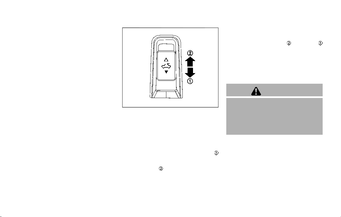
2-66 Instruments and controls
during this period of about 45 seconds,
power to the moonroof is canceled.
JVI0614X
Sunshade
The sunshade will open automatically
when the moonroof is opened. However,
it must be closed manually.
Tilting the moonroof
To tilt up, first close the moonroof, then
push the switch to the TILT UP position
and release it; it need not be held. To tilt
down the moonroof, push the switch to
the TILT DOWN
position.
Sliding the moonroof
To fully open or close the moonroof, push
the switch to the OPEN
or CLOSE
position and release it; it need not be held.
The roof will automatically open or close
all the way. To stop the roof, push the
switch once more while it is opening or
closing.
Auto reverse function
WARNING
There are some small distances im-
mediately before the closed position
which cannot be detected. Make sure
that all passengers have their hands,
etc., inside the vehicle before closing
the moonroof.
If the control unit detects something
caught in the moonroof when it is closing,
the moonroof will be immediately
opened.
The auto reverse function can be acti-
vated when the moonroof is closed by
automatic operation when the ignition
switch is in the ON position or for about
45 seconds after the ignition switch is
pushed to the OFF position.
If the moonroof cannot be closed auto-
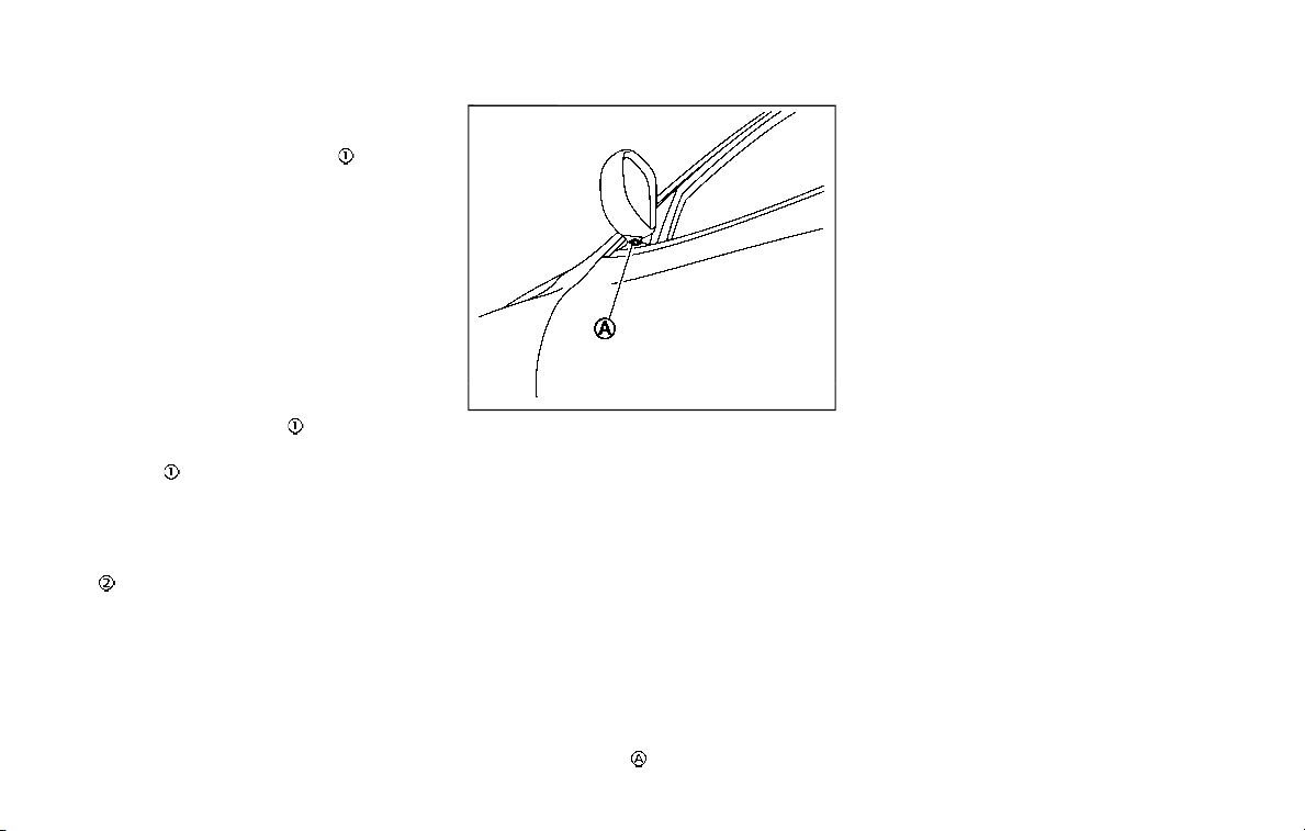
matically when the auto reverse function
activates due to a malfunction, push and
hold the switch to the CLOSE
position.
Depending on the environment or driv-
ing conditions, the auto reverse func-
tion may be activated if an impact or
load similar to something being caught
in the moonroof occurs.
If the moonroof does not operate
If the moonroof does not operate prop-
erly, perform the following procedure to
initialize the moonroof operation system.
1. If the moonroof is open, close it fully
by repeatedly pushing the moonroof
switch to the CLOSE
position.
2. Push and hold the switch to the
CLOSE
position.
3. Release the moonroof switch after the
moonroof moves slightly up and
down.
4. Push and hold the switch to the OPEN
position to fully tilt the moonroof
down.
5. Check if the moonroof switch oper-
ates normally.
If the moonroof does not operate prop-
erly after performing the procedure
above, have your moonroof checked and
repaired. It is recommended you visit a
NISSAN dealer for this service.
SIC3642
To activate or deactivate the welcome
light function, perform the following pro-
cedure.
1. Place the ignition switch in the ON
position.
2. Open the driver’s side door.
3. Within 20 seconds after the ignition
switch is placed in the ON position,
push the door open request switch on
the driver’s side door handle for more
than 5 seconds with the driver’s door
open.
4. A chime sounds when the setting is
completed.
Once the welcome light function is active,
the puddle light
and the passenger
cabin illumination will illuminate when
you approach the vehicle with the Intel-
ligent Key (within approximately 3.3 ft (1
m) of the antenna built inside the door
handles) and the following conditions are
met.
. All doors are closed and locked.
. The ignition switch is in the LOCK or
OFF position.
. The Intelligent Key is outside the
vehicle.
. The puddle light operates within a set
duration.
BATTERY SAVER SYSTEM
The welcome light function will be deac-
tivated automatically to prevent battery
discharge under the following conditions.
To activate the welcome light function
again, unlock any door.
. If the welcome light function does not
operate within a set duration. Note
that the duration is set to 9 days as
the factory default setting.
. If the welcome light function is acti-
vated 15 consecutive times when you
approach and leave the vehicle with
the Intelligent Key without the doors
being unlocked.
Instruments and controls 2-67
WELCOME LIGHT (if so equipped)
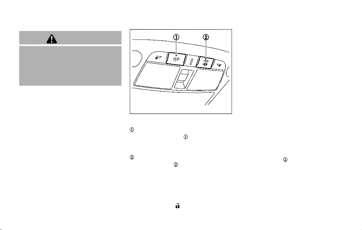
2-68 Instruments and controls
CAUTION
. Turn off the lights when you leave
the vehicle.
. Do not use the lights for extended
periods of time with the engine
stopped. This could result in a
discharged battery.
JVI0760X
INTERIOR LIGHT SWITCH
ON switch
When the ON switch is pushed in, the
map lights and rear personal lights will
illuminate.
DOOR OFF switch
When the switch is not pushed in, the
map lights and rear personal lights will
illuminate for a period of time under the
following conditions:
. when the ignition switch is placed in
the OFF position.
. when doors are unlocked by pushing
the UNLOCK
button on the In-
telligent Key or door handle request
switch with the ignition switch in the
OFF position.
. when any door is opened and then
closed with the ignition switch in the
OFF position.
. when any door is opened with the
ignition switch in the ACC or ON
position.
— The lights will remain on while the
door is opened. When the door is
closed, the lights will turn off.
When the “Lamp ON When Door Unlocks”
key is set to the OFF position (see
NissanConnect® Owner’s Manual), the
lights will illuminate under the following
condition:
. any door is opened with the ignition
switch in any position
— remain on while the door is opened.
When the door is closed, the lights
go off.
When the switch
is pushed in, the map
lights and rear personal lights will not
illuminate under the above condition.
INTERIOR LIGHTS

JVI0759X
CONSOLE LIGHT
The console light will turn on whenever
the clearance lights or headlights are
illuminated.
JVI0758X
MAP LIGHTS
Push the button as illustrated to turn the
light on or off.
SIC3250
REAR PERSONAL LIGHTS
Push the button as illustrated to turn the
light on or off.
Instruments and controls 2-69
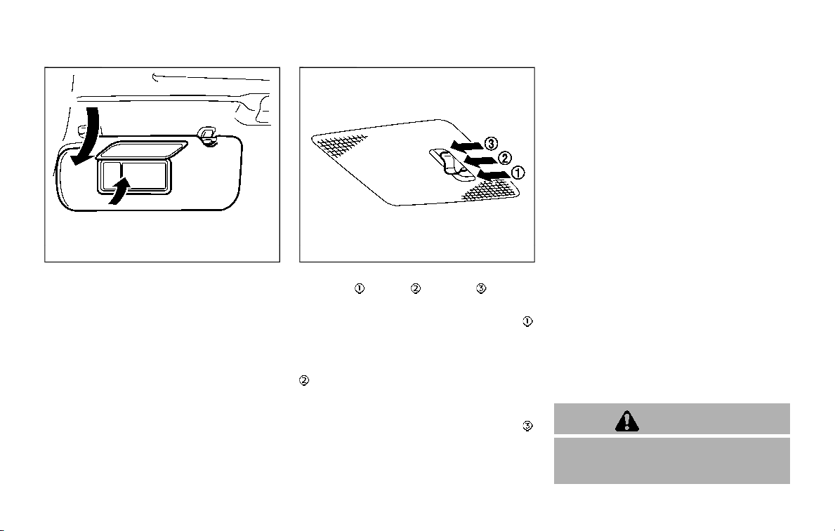
2-70 Instruments and controls
SIC4448
The light on the vanity mirror will turn on
when the cover on the vanity mirror is
opened.
When the cover is closed, the light will
turn off.
The lights will also turn off after a
period of time when the lights remain
illuminated to prevent the battery from
becoming discharged.
SIC4418
The cargo light switch has three posi-
tions: ON
, center and OFF .
ON position
When the switch is in the ON position
,
the cargo light will illuminate.
Center position
When the switch is in the center position
, the cargo light will illuminate when the
liftgate is opened.
OFF position
When the switch is in the OFF position
,
the cargo light will not illuminate.
The HomeLink® Universal Transceiver
provides a convenient way to consolidate
the functions of up to three individual
hand-held transmitters into one built-in
device.
HomeLink® Universal Transceiver:
. Will operate most Radio Frequency
(RF) devices such as garage doors,
gates, home and office lighting, entry
door locks and security systems.
. Is powered by your vehicle’s battery.
No separate batteries are required. If
the vehicle’s battery is discharged or is
disconnected, HomeLink® will retain
all programming.
When the HomeLink® Universal Trans-
ceiver is programmed, retain the origi-
nal transmitter for future programming
procedures (Example: new vehicle pur-
chases). Upon sale of the vehicle, the
programmed HomeLink® Universal
Transceiver buttons should be erased
for security purposes. For additional
information, refer to “Programming
HomeLink®” (P.2-71).
WARNING
. Do not use the HomeLink® Uni-
versal Transceiver with any gar-
age door opener that lacks safety
VANITY MIRROR LIGHTS CARGO LIGHT
HomeLink® UNIVERSAL TRANSCEIVER
(Type A) (if so equipped)
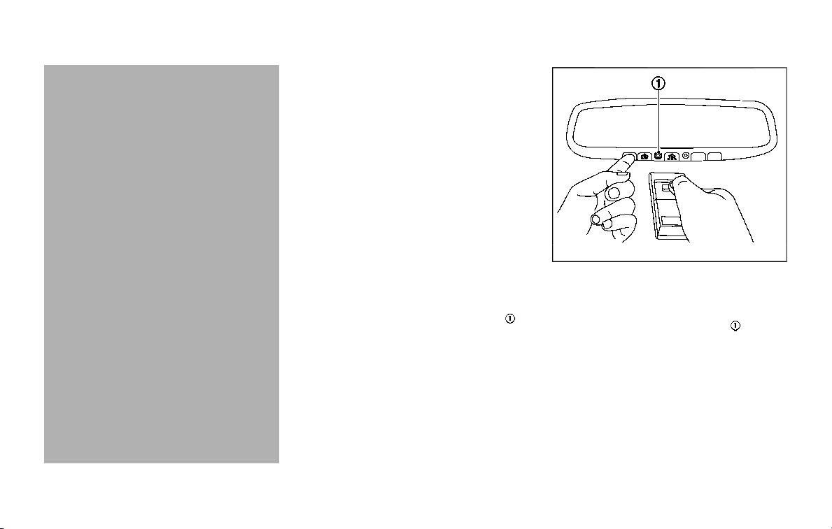
stop and reverse features as re-
quired by federal safety stan-
dards. (These standards became
effective for opener models man-
ufactured after April 1, 1982). A
garage door opener which cannot
detect an object in the path of a
closing garage door and then
automatically stop and reverse,
does not meet current federal
safety standards. Using a garage
door opener without these fea-
tures increases the risk of serious
injury or death.
. During the programming proce-
dure your garage door or security
gate will open and close (if the
transmitter is within range). Make
sure that people or objects are
clear of the garage door, gate,
etc. that you are programming.
. Your vehicle’s engine should be
turned off while programming
the HomeLink® Universal Trans-
ceiver. Do not breathe exhaust
gases; they contain colorless
and odorless carbon monoxide.
Carbon monoxide is dangerous. It
can cause unconsciousness or
death.
PROGRAMMING HomeLink®
The following steps show generic instruc-
tions how to program a HomeLink®
button. If you have any questions or are
having difficulty programming your
HomeLink® buttons, refer to the
HomeLink® web site at: www.homelink.
com/nissan or call 1-800-355-3515.
NOTE:
It is also recommended that a new
battery be placed in the hand-held
transmitter of the device being pro-
grammed to HomeLink® for quicker
programming and accurate transmis-
sion of the radio-frequency.
1. Position the end of your hand-held
transmitter 1-3 in (26-76 mm) away
from the HomeLink® surface, keeping
the HomeLink® indicator light
in
view.
JVI0428X
2. Using both hands, simultaneously
press and hold the desired HomeLink®
button and handheld transmitter but-
ton. DO NOT release until the
HomeLink® indicator light
flashes
slowly and then rapidly. When the
indicator light flashes rapidly, both
buttons may be released. (The rapid
flashing indicates successful pro-
gramming.)
NOTE:
Some devices to be programmed
may require you to replace Step 2
with the cycling procedure noted in
the “Programming HomeLink® for
Canadian customers and gate open-
ers” (P.2-72).
Instruments and controls 2-71
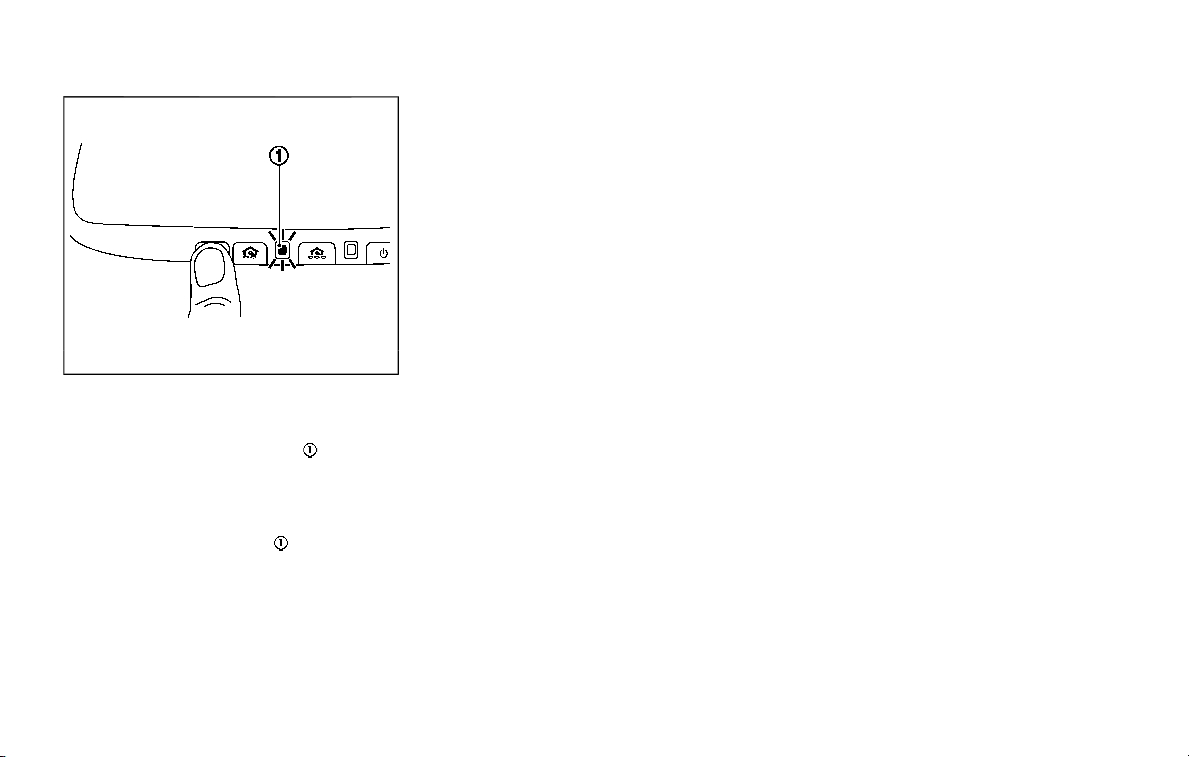
2-72 Instruments and controls
JVI0429X
3. Press and hold the programmed
HomeLink® button and observe the
indicator light.
.
If the indicator light is solid/
continuous, programming is com-
plete and your device should acti-
vate when the HomeLink® button is
pressed and released.
.
If the indicator light
blinks rapidly
for two seconds and then turns to a
solid/continuous light, continue
with Steps 4-6 for a rolling code
device. A second person may make
the following steps easier. Use a
ladder or other device. Do not stand
on your vehicle to perform the next
steps.
4. At the receiver located on the garage
door opener motor in the garage,
locate the “learn” or “smart” button
(the name and color of the button
may vary by manufacturer but it is
usually located near where the hang-
ing antenna wire is attached to the
unit). If there is difficulty locating the
button, reference the garage door
opener’s manual.
5. Press and release the “learn” or “smart”
button.
NOTE:
Once the button is pressed, you have
approximately 30 seconds to initiate
the next step.
6. Return to the vehicle and firmly press
and hold the programmed HomeLink®
button for two seconds and release.
Repeat the “press/hold/release” se-
quence up to 3 times to complete
the programming process. HomeLink®
should now activate your rolling code
equipped device.
7. If you have any questions or are
having difficulty programming your
HomeLink® buttons, refer to the
HomeLink® web site at: www.
homelink.com/nissan or call 1-800-
355-3515.
PROGRAMMING HomeLink® FOR
CANADIAN CUSTOMERS AND GATE
OPENERS
Canadian radio-frequency laws require
transmitter signals to “time-out” (or quit)
after several seconds of transmission –
which may not be long enough for
HomeLink® to pick up the signal during
programming. Similar to this Canadian
law, some U.S. gate operators are de-
signed to “time-out” in the same manner.
If you live in Canada or you are having
difficulties programming a gate operator
or garage door opener by using the
“Programming HomeLink®” procedures,
replace “Programming HomeLink®” Step
2 with the following:
NOTE:
When programming a garage door
opener, etc., unplug the device during
the “cycling” process to prevent possi-
ble damage to the garage door opener
components.
Step 2: Using both hands, simultaneously
press and hold the desired HomeLink®
button and the hand-held transmitter
button. During programming, your hand-
held transmitter may automatically stop
transmitting. Continue to press and hold
the desired HomeLink® button while you
press and re-press (“cycle”) your hand-

held transmitter every two seconds until
the frequency signal has been learned.
The HomeLink® indicator light will flash
slowly and then rapidly after several
seconds upon successful programming.
DO NOT release until the HomeLink®
indicator light flashes slowly and then
rapidly. When the indicator light flashes
rapidly, both buttons may be released.
The rapid flashing indicates successful
programming.
Proceed with “Programming HomeLink®”
step 3 to complete.
Remember to plug the device back in
when programming is completed.
OPERATING THE HomeLink® UNI-
VERSAL TRANSCEIVER
The HomeLink® Universal Transceiver,
after it is programmed, can be used to
activate the programmed device. To op-
erate, simply press and release the appro-
priate programmed HomeLink® Universal
Transceiver button. The amber indicator
light will illuminate while the signal is
being transmitted.
For convenience, the hand-held transmit-
ter of the device may also be used at any
time.
PROGRAMMING TROUBLESHOOT-
ING
If the HomeLink® does not quickly learn
the hand-held transmitter information:
. replace the hand-held transmitter
batteries with new batteries.
. position the hand-held transmitter
with its battery area facing away from
the HomeLink® surface.
. press and hold both the HomeLink®
and hand-held transmitter buttons
without interruption.
. position the hand-held transmitter 1-3
in (26-76 mm) away from the
HomeLink® surface. Hold the transmit-
ter in that position for up to 15
seconds. If HomeLink® is not pro-
grammed within that time, try holding
the transmitter in another position -
keeping the indicator light in view at
all times.
If you have any questions or are having
difficulty programming your HomeLink®
buttons, refer to the HomeLink® web site
at: www.homelink.com/nissan or 1-800-
355-3515.
CLEARING THE PROGRAMMED IN-
FORMATION
The following procedure clears the pro-
grammed information from both buttons.
Individual buttons cannot be cleared.
However, individual buttons can be re-
programmed, see “Reprogramming a sin-
gle HomeLink® button” (P.2-73).
To clear all programming
1. Press and hold the two outer
HomeLink® buttons until the indicator
light begins to flash in approximately
10 seconds. Do not hold for longer
than 20 seconds.
2. Release both buttons.
HomeLink® is now in the programming
mode and can be programmed at any
time beginning with “Programming
HomeLink®” - Step 1.
REPROGRAMMING A SINGLE
HomeLink® BUTTON
To reprogram a HomeLink® Universal
Transceiver button, complete the follow-
ing.
1. Press and hold the desired HomeLink®
button. Do not release the button.
2. The indicator light will begin to flash
after 20 seconds. Without releasing
the HomeLink® button, proceed with
Instruments and controls 2-73

2-74 Instruments and controls
“Programming HomeLink®” - Step 1.
For questions or comments, contact
HomeLink® at: www.homelink.com/
nissan or 1-800-355-3515.
The HomeLink® Universal Transceiver
button has now been reprogrammed.
The new device can be activated by
pushing the HomeLink® button that was
just programmed. This procedure will not
affect any other programmed HomeLink®
buttons.
IF YOUR VEHICLE IS STOLEN
If your vehicle is stolen, you should
change the codes of any non-rolling code
device that has been programmed into
HomeLink®. Consult the Owner’s Manual
of each device or call the manufacturer or
dealer of those devices for additional
information.
When your vehicle is recovered, you will
need to reprogram the HomeLink® Uni-
versal Transceiver with your new trans-
mitter information.
FCC Notice:
For USA:
This device complies with Part 15 of the
FCC Rules. Operation is subject to the
following two conditions: (1) This device
may not cause harmful interference,
and (2) this device must accept any
interference received, including inter-
ference that may cause undesired op-
eration.
NOTE:
Changes or modifications not expressly
approved by the party responsible for
compliance could void the user’s
authority to operate the equipment.
For Canada:
This device complies with Industry Ca-
nada licence-exempt RSS standard(s).
Operation is subject to the following
two conditions: (1) this device may not
cause interference, and (2) this device
must accept any interference, including
interference that may cause undesired
operation of the device.
The HomeLink® Universal Transceiver
provides a convenient way to consolidate
the functions of up to three individual
hand-held transmitters into one built-in
device.
HomeLink® Universal Transceiver:
. Will operate most Radio Frequency
(RF) devices such as garage doors,
gates, home and office lighting, entry
door locks and security systems.
. Is powered by your vehicle’s battery.
No separate batteries are required. If
the vehicle’s battery is discharged or is
disconnected, HomeLink® will retain
all programming.
When the HomeLink® Universal Trans-
ceiver is programmed, retain the origi-
nal transmitter for future programming
procedures (Example: new vehicle pur-
chases). Upon sale of the vehicle, the
programmed HomeLink® Universal
Transceiver buttons should be erased
for security purposes. For additional
information, refer to “Programming
HomeLink®” (P.2-75).
WARNING
. Do not use the HomeLink® Uni-
versal Transceiver with any gar-
age door opener that lacks safety
HomeLink® UNIVERSAL TRANSCEIVER
(Type B) (if so equipped)
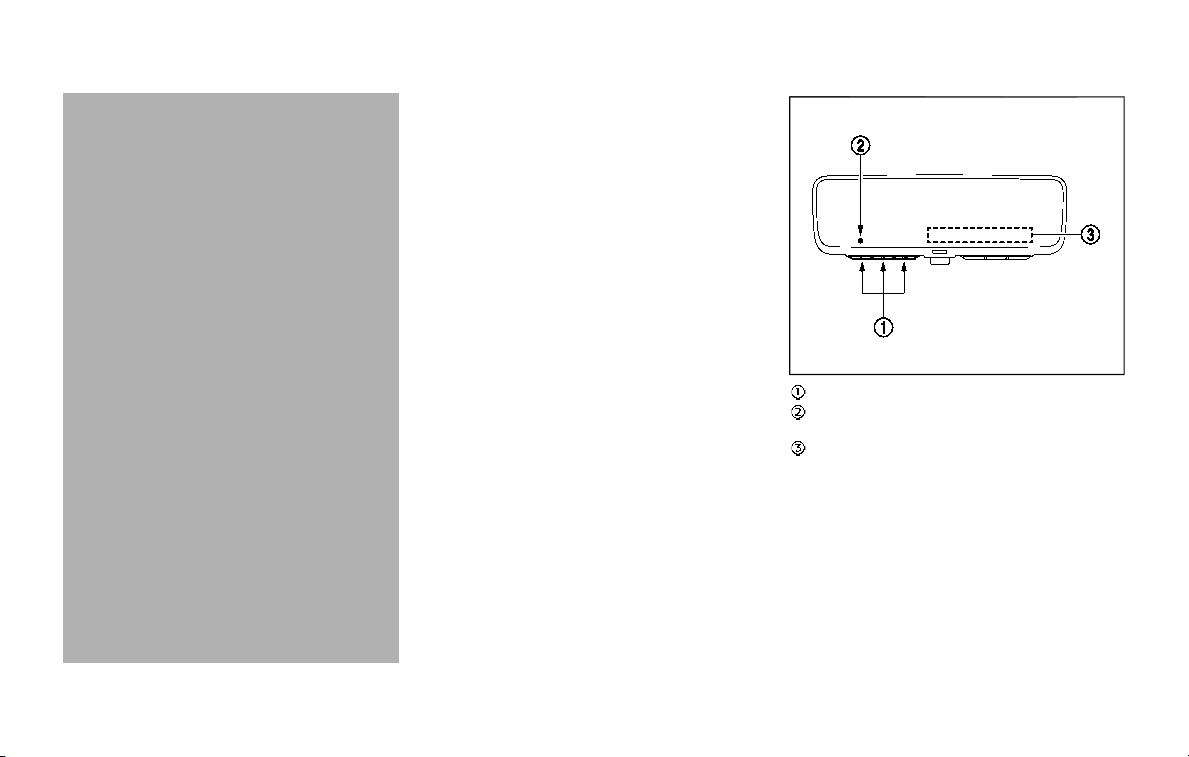
stop and reverse features as re-
quired by federal safety stan-
dards. (These standards became
effective for opener models man-
ufactured after April 1, 1982). A
garage door opener which cannot
detect an object in the path of a
closing garage door and then
automatically stop and reverse,
does not meet current federal
safety standards. Using a garage
door opener without these fea-
tures increases the risk of serious
injury or death.
. During the programming proce-
dure your garage door or security
gate will open and close (if the
transmitter is within range). Make
sure that people or objects are
clear of the garage door, gate,
etc. that you are programming.
. Your vehicle’s engine should be
turned off while programming
the HomeLink® Universal Trans-
ceiver. Do not breathe exhaust
gases; they contain colorless
and odorless carbon monoxide.
Carbon monoxide is dangerous. It
can cause unconsciousness or
death.
PROGRAMMING HomeLink®
The following steps show generic instruc-
tions how to program a HomeLink®
button. If you have any questions or are
having difficulty programming your
HomeLink® buttons, refer to the
HomeLink® web site at: www.homelink.
com/nissan or call 1-800-355-3515.
NOTE:
It is also recommended that a new
battery be placed in the hand-held
transmitter of the device being pro-
grammed to HomeLink® for quicker
programming and accurate transmis-
sion of the radio-frequency.
JVI1689X
HomeLink® buttons (1-3)
Indicator light (appears above each
HomeLink® button)
Status display (where the current condi-
tion of the HomeLink® is displayed)
Instruments and controls 2-75
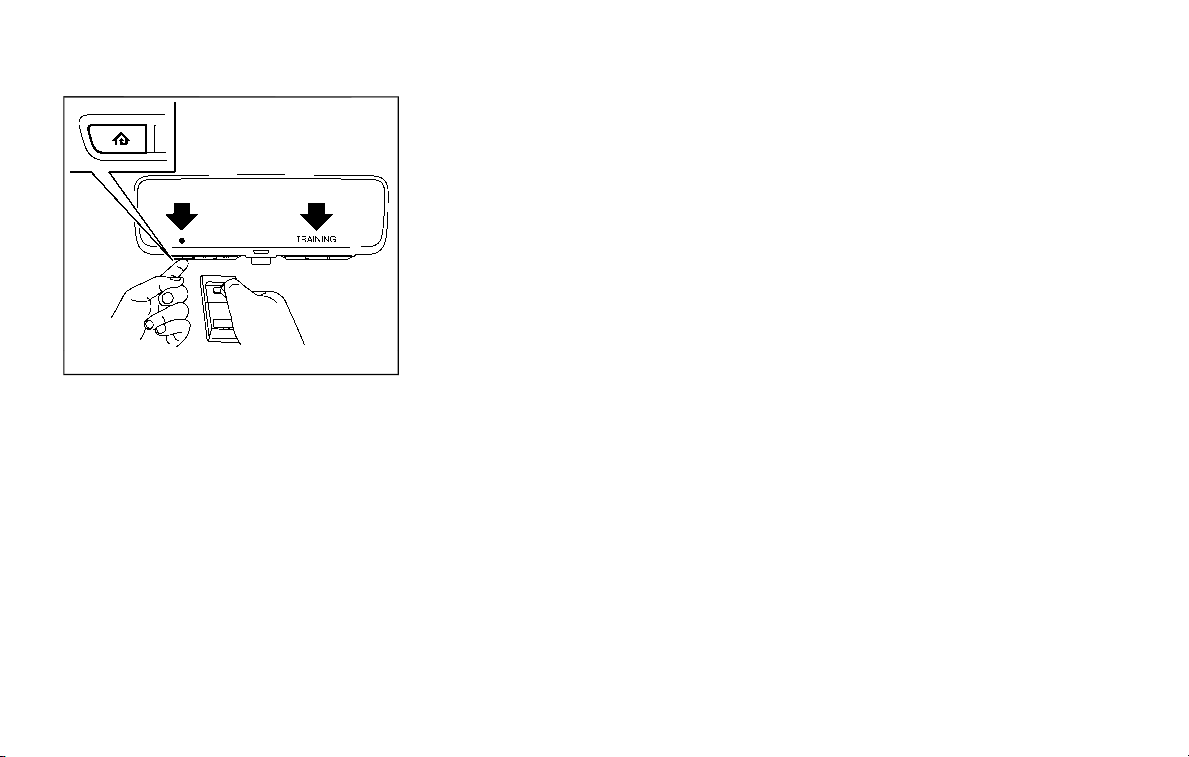
2-76 Instruments and controls
JVI1639X
1. Press and release the desired
HomeLink® button. The indicator light
flashes in orange and “TRAINING” is
displayed on the mirror.
2. Position the end of your hand-held
transmitter 1 to 3 in (2 to 8 cm) away
from the HomeLink® button. For some
devices, it may have better commu-
nication when the hand-held trans-
mitter is positioned 6 to 12 in (15 to 30
cm) away from the HomeLink® button.
3. While the indicator light is flashing in
orange, press and hold the hand-held
transmitter button. DO NOT release
until the HomeLink® indicator light
changes from orange to green and
“TRAINED” is displayed on the mirror.
When the indicator light illuminates in
green, the hand-held transmitter but-
ton may be released.
NOTE:
Some devices to be programmed
may require you to replace the Step
3 with the cycling procedure noted
in “Programming HomeLink® for Ca-
nadian customers and gate open-
ers” (P.2-77).
4. Press and hold the programmed
HomeLink® button and observe the
indicator light.
.
If the indicator light remains green
(solid/continuous), programming is
complete and your device should
activate when the HomeLink® but-
ton is pressed and released.
.
If the indicator light rapidly flashes
in green, press and hold the pro-
grammed HomeLink® button for 2
seconds. Repeat the “press/hold/
release” sequence up to three times
to complete the programming pro-
cess. If the device operates, the
programming is complete. If the
device still does not operate, con-
tinue with Steps 5-7 for the device
being programmed to HomeLink®.
A second person may make the
following steps easier. Use a ladder
or other device. Do not stand on
your vehicle to perform the next
steps.
5. At the garage door opener motor in
the garage, locate the “Learn,” “Smart”
or “Program” button (the name and
color of the button may vary by
manufacturer but it is usually located
near where the hanging antenna wire
is attached to the unit). If there is
difficulty locating the button, refer-
ence the garage door opener’s man-
ual.
6. Firmly press and then release the
“Learn,” “Smart” or “Program” button.
NOTE:
Once the button is pressed, you have
approximately 30 seconds to initiate
the next step.
7. Return to the vehicle and firmly press
and hold the programmed HomeLink®
button for 2 seconds and release.
Repeat the “press/hold/release” se-
quence up to three times to complete
the programming process. Then your
device should operate when the
HomeLink® button is pressed and
released.
8. If you have any questions or are
having difficulty programming your
HomeLink® buttons, refer to the

HomeLink® web site at: www.
homelink.com/nissan or call 1-800-
355-3515.
PROGRAMMING HomeLink® FOR
CANADIAN CUSTOMERS AND GATE
OPENERS
Canadian radio-frequency laws require
transmitter signals to “time-out” (or quit)
after several seconds of transmission –
which may not be long enough for
HomeLink® to pick up the signal during
programming. Similar to this Canadian
law, some U.S. gate operators are de-
signed to “time-out” in the same manner.
If you live in Canada or you are having
difficulties programming a gate operator
or garage door opener by using the
“Programming HomeLink®” procedures,
replace “Programming HomeLink®” Step
3 with the following:
NOTE:
When programming a garage door
opener, etc., unplug the device during
the “cycling” process to prevent possi-
ble damage to the device components.
Step 3: While the HomeLink® indicator
light is flashing in orange, press and
release (“cycling”) the hand-held transmit-
ter button every 2 seconds. Continue to
press and release the hand-held trans-
mitter button until the HomeLink® indi-
cator light changes from orange to green.
When the indicator light illuminates in
green, hand-held transmitter button may
be released.
Proceed with “Programming HomeLink®”
step 4 to complete.
Remember to plug the device back in
when programming is completed.
OPERATING THE HomeLink® UNI-
VERSAL TRANSCEIVER
The HomeLink® Universal Transceiver,
after it is programmed, can be used to
activate the programmed device. To op-
erate, firmly press the appropriate pro-
grammed HomeLink® button. The
indicator light will illuminate in green with
three parenthesis
on the mirror
while the signal is being transmitted.
PROGRAMMING TROUBLESHOOT-
ING
If the HomeLink® does not quickly learn
the hand-held transmitter information:
. replace the hand-held transmitter
batteries with new batteries.
. position the hand-held transmitter
with its battery area facing away from
the HomeLink® button.
. press and hold the HomeLink® button
and hand-held transmitter button in
each step without interruption.
. position the hand-held transmitter 1
to 3 in (2 to 8 cm) away from the
HomeLink® button. Hold the transmit-
ter in that position for up to 15
seconds. If HomeLink® is not pro-
grammed within that time, try holding
the transmitter in another position -
for example, 6 to 12 in (15 to 30 cm)
away, keeping the HomeLink® button
in view at all times.
If you have any questions or are having
difficulty programming your HomeLink®
buttons, refer to the HomeLink® web site
at: www.homelink.com/nissan or 1-800-
355-3515.
CLEARING THE PROGRAMMED IN-
FORMATION
The following procedure clears the pro-
grammed information from three but-
tons. Individual buttons cannot be
cleared. However, individual buttons can
be reprogrammed, see “Reprogramming
a single HomeLink® button” (P.2-78).
To clear all programming
1. Press and hold the two outer
HomeLink® buttons until the indicator
light begins to flash in green and
“CLEARED” is displayed on the mirror,
in approximately 10 seconds. Do not
hold for longer than 20 seconds.
Instruments and controls 2-77
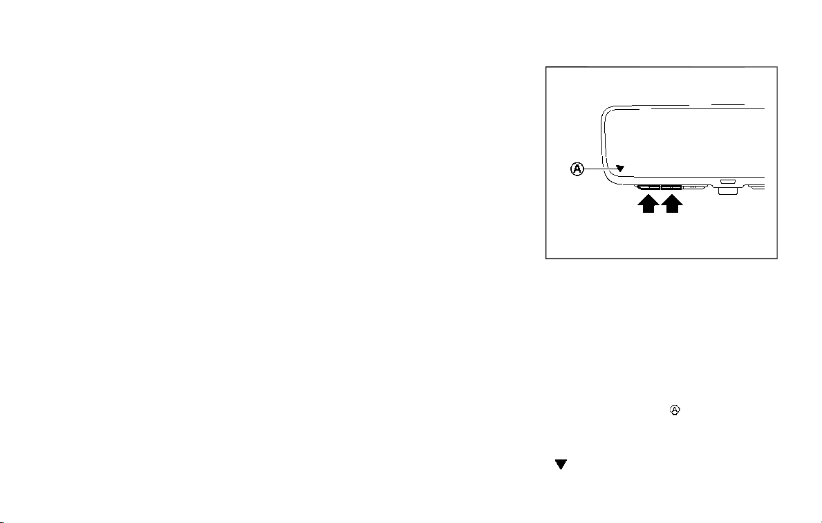
2-78 Instruments and controls
2. Release both buttons.
HomeLink® is now in the programming
mode and can be programmed at any
time beginning with “Programming
HomeLink®” - Step 1.
REPROGRAMMING A SINGLE
HomeLink® BUTTON
To reprogram a HomeLink® button, com-
plete the following.
1. Press and hold the desired HomeLink®
button. DO NOT release the button.
2. The indicator light will illuminate in
green, and after 20 seconds it will
begin to flash in orange and “TRAIN-
ING” is displayed on the mirror.
3. Release the HomeLink® button and
proceed with “Programming
HomeLink®” — Step 3.
For questions or comments, contact
HomeLink® at: www.homelink.com/
nissan or 1-800-355-3515.
The HomeLink® button has now been
reprogrammed. The new device can be
activated by pressing the HomeLink®
button that was just programmed. This
procedure will not affect any other pro-
grammed HomeLink® buttons.
If a new device is not programmed to the
HomeLink® button, it will revert to the
previously stored programming.
USING THE GARAGE DOOR TWO-
WAY COMMUNICATION
HomeLink® has the function of commu-
nicating with garage door opener sys-
tems. If your garage door openers are
compatible with HomeLink®, the
HomeLink® can:
. receive and display “closing” or “open-
ing” status from your garage door
opener.
. recall and display the garage door
being “closed” or “opened”.
HomeLink® can receive the status from a
garage door opener at a range up to 820
ft (250 m), but it varies depending on the
environment. You may need to reduce
vehicle speed to successfully receive the
garage door opener communication.
Programming two-way communi-
cation
After programming a new HomeLink®
button, proceed with “Programming
HomeLink®” Step 6 to enable two-way
communication. If the garage door status
indicator appears on the left side on the
mirror when pressing the programmed
HomeLink® button, the two-way commu-
nication programming is complete.
JVI1640X
Using two-way communication
Press and hold the HomeLink® buttons (1
and 2) simultaneously for 2 seconds to
recall and display the last recorded gar-
age door status communicated to
HomeLink®. HomeLink® will display the
last recorded status for 3 seconds.
If two-way communication programming
is successful, HomeLink® will display the
status of your garage door opener with
the status indicator
, which changes
depending on the status. The garage
door opener status indicator shows the
garage door opener status as follows:
Flashing in orange – Closing

Flashing in orange – Opening
Illuminating in green – Closed
Illuminating in green – Opened
The status indicator stops to flash after
an open/close signal is received or no
signal is received within 30 seconds from
the garage door opener.
IF YOUR VEHICLE IS STOLEN
If your vehicle is stolen, you should
change the codes of any non-rolling code
device that has been programmed into
HomeLink®. Consult the Owner’s Manual
of each device or call the manufacturer or
dealer of those devices for additional
information.
When your vehicle is recovered, you will
need to reprogram the HomeLink® Uni-
versal Transceiver with your new trans-
mitter information.
FCC Notice:
For USA:
This device complies with Part 15 of the
FCC Rules. Operation is subject to the
following two conditions: (1) This device
may not cause harmful interference,
and (2) this device must accept any
interference received, including inter-
ference that may cause undesired op-
eration.
NOTE:
Changes or modifications not expressly
approved by the party responsible for
compliance could void the user’s
authority to operate the equipment.
For Canada:
This device complies with Industry Ca-
nada licence-exempt RSS standard(s).
Operation is subject to the following
two conditions: (1) this device may not
cause interference, and (2) this device
must accept any interference, including
interference that may cause undesired
operation of the device.
Instruments and controls 2-79

2-80 Instruments and controls
MEMO

3 Pre-driving checks and adjustments
Keys ......................................................................................................... 3-2
Intelligent Key ........................................................................... 3-2
Valet hand-off........................................................................... 3-4
Doors ...................................................................................................... 3-4
Locking with mechanical key ...................................... 3-4
Opening and closing windows with the
mechanical key ........................................................................ 3-5
Locking with inside lock knob ..................................... 3-5
Locking with power door lock switch................... 3-5
Automatic door locks ......................................................... 3-6
Child safety rear door lock ........................................... 3-6
Intelligent Key system .............................................................. 3-7
Intelligent Key operating range ................................. 3-9
Door locks/unlocks precaution .................................. 3-9
Intelligent Key operation .............................................. 3-10
Battery saver system ....................................................... 3-12
Warning signals .................................................................... 3-12
Troubleshooting guide ................................................... 3-13
Remote keyless entry system ......................................... 3-15
How to use remote keyless entry system ...... 3-16
Remote engine start (if so equipped) ....................... 3-19
Remote engine start operating range............... 3-19
Remote starting the engine ....................................... 3-19
Extending engine run time ......................................... 3-20
Canceling a remote engine start ........................ 3-20
Conditions the remote engine start will
not work .................................................................................. 3-20
Hood .................................................................................................... 3-21
Liftgate .............................................................................................. 3-22
Operating manual liftgate ......................................... 3-22
Operating power liftgate (if so equipped) ...... 3-22
Auto closure ........................................................................ 3-25
Liftgate release lever ..................................................... 3-26
Fuel-filler door ............................................................................. 3-26
Opening the fuel-filler door...................................... 3-26
Fuel-filler cap ....................................................................... 3-27
Tilt/telescopic steering ........................................................ 3-29
Electric operation ............................................................. 3-30
Sun visors ........................................................................................ 3-30
Mirrors................................................................................................ 3-31
Inside mirror ......................................................................... 3-31
Outside mirrors .................................................................. 3-38
Vanity mirror ........................................................................ 3-40
Automatic drive positioner (if so equipped) ........ 3-40
Entry/exit function .......................................................... 3-40
Memory storage ................................................................ 3-41
Setting memory function........................................... 3-42
System operation ............................................................. 3-42
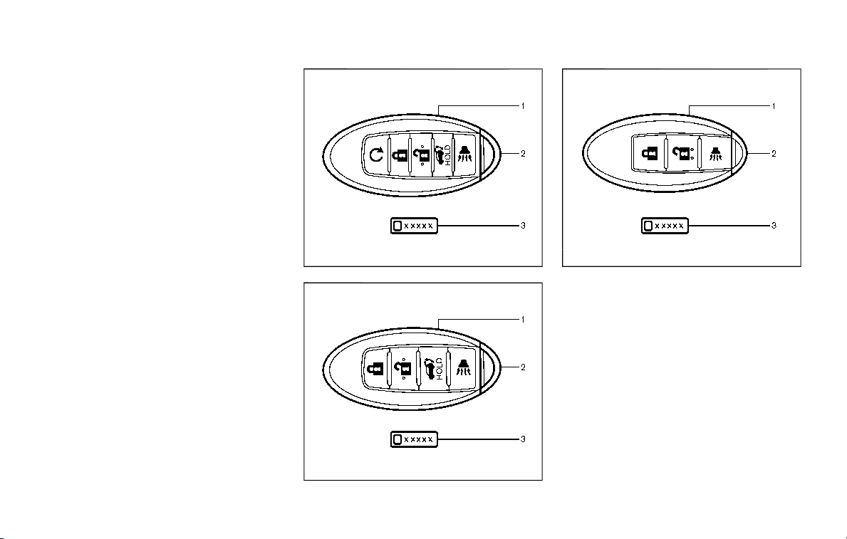
3-2 Pre-driving checks and adjustments
A key number plate is supplied with your
keys. Record the key number and keep it
in a safe place (such as your wallet), not in
the vehicle. If you lose your keys, it is
recommended you visit a NISSAN dealer
for duplicates by using the key number.
NISSAN does not record any key numbers
so it is very important to keep track of
your key number plate.
A key number is only necessary when you
have lost all keys and do not have one to
duplicate from. If you still have a key, it
can be duplicated without knowing the
key number.
JVP0155X
Type A (if so equipped)
SPA2717
Type B (if so equipped)
SPA2406
Type C (if so equipped)
1. Intelligent Key (2)
2. Mechanical key (inside Intelligent Key) (2)
3. Key number plate (1)
INTELLIGENT KEY
Your vehicle can only be driven with the
Intelligent Keys which are registered to
your vehicle’s Intelligent Key system com-
ponents and NISSAN Vehicle Immobilizer
System components. As many as 4 In-
telligent Keys can be registered and used
with one vehicle. The new keys must be
registered by a NISSAN dealer prior to use
with the Intelligent Key system and
NISSAN Vehicle Immobilizer System of
your vehicle. Since the registration pro-
cess requires erasing all memory in the
KEYS
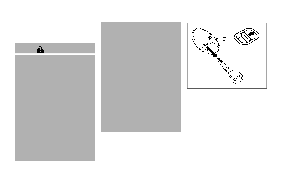
Intelligent Key components when regis-
tering new keys, be sure to take all
Intelligent Keys that you have to the
NISSAN dealer.
CAUTION
. Be sure to carry the Intelligent
Key with you when driving. The
Intelligent Key is a precision de-
vice with a built-in transmitter. To
avoid damaging it, please note
the following.
— The Intelligent Key is water
resistant; however, wetting
may damage the Intelligent
Key. If the Intelligent Key gets
wet, immediately wipe until it
is completely dry.
— Do not bend, drop or strike it
against another object.
— If the outside temperature is
below 14°F (−10°C), the battery
of the Intelligent Key may not
function properly.
— Do not place the Intelligent
Key for an extended period in
a place where temperatures
exceed 140°F (60°C).
— Do not change or modify the
Intelligent Key.
— Do not use a magnet key
holder.
— Do not place the Intelligent
Key near an electric appliance
such as a television set or
personal computer.
— Do not allow the Intelligent
Key to come into contact with
water or salt water, and do
not wash it in a washing
machine. This could affect
the system function.
. If an Intelligent Key is lost or
stolen, NISSAN recommends
erasing the ID code of that Intel-
ligent Key. This will prevent the
Intelligent Key from unauthorized
use to unlock the vehicle. For
information regarding the eras-
ing procedure, it is recommended
you visit a NISSAN dealer.
SPA2033
Mechanical key
To remove the mechanical key, release
the lock knob at the back of the Intelli-
gent Key.
To install the mechanical key, firmly insert
it into the Intelligent Key until the lock
knob returns to the lock position.
Use the mechanical key to lock or unlock
the doors and the glove box.
See “Doors” (P.3-4) and “Storage” (P.2-53).
Pre-driving checks and adjustments 3-3
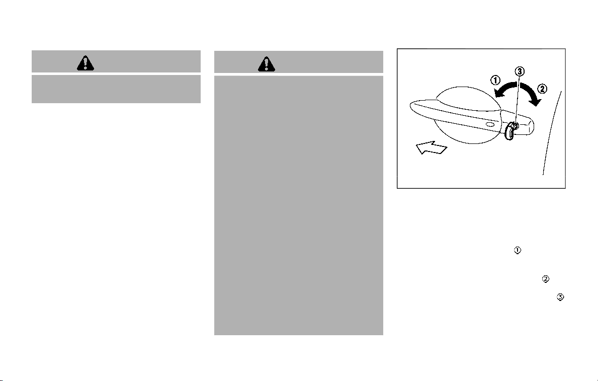
3-4 Pre-driving checks and adjustments
CAUTION
Always carry the mechanical key
installed in the Intelligent Key.
VALET HAND-OFF
When you have to leave a key with a valet,
give them the Intelligent Key itself and
keep the mechanical key with you to
protect your belongings.
To prevent the glove box from being
opened during valet hand-off, follow the
procedures below.
1. Remove the mechanical key from the
Intelligent Key.
2. Lock the glove box with the mechan-
ical key.
3. Hand the Intelligent Key to the valet,
keeping the mechanical key in your
pocket or bag for insertion into the
Intelligent Key when you retrieve your
vehicle.
See “Storage” (P.2-53).
WARNING
. Always have the doors locked
while driving. Along with the use
of seat belts, this provides great-
er safety in the event of an
accident by helping to prevent
persons from being thrown from
the vehicle. This also helps keep
children and others from unin-
tentionally opening the doors,
and will help keep out intruders.
. Before opening any door, always
look for and avoid oncoming
traffic.
. To help avoid risk of injury or
death through unintended opera-
tion of the vehicle and or its
systems, including entrapment
in windows or inadvertent door
lock activation, do not leave chil-
dren, people who require the
assistance of others or pets un-
attended in your vehicle. Addi-
tionally, the temperature inside a
closed vehicle on a warm day can
quickly become high enough to
cause a significant risk of injury
or death to people and pets.
SPA2457B
LOCKING WITH MECHANICAL KEY
The power door lock system allows you to
lock or unlock all doors simultaneously
using the mechanical key.
. Turning the driver’s door key cylinder
to the front of the vehicle
will lock all
doors.
. Turning the driver’s door key cylinder
once to the rear of the vehicle
will
unlock the driver’s door. After return-
ing the key to the neutral position
,
turning it to the rear again within 5
seconds will unlock all doors.
. You can switch the lock system to the
mode that allows you to open all the
doors when the key is turned once.
DOORS
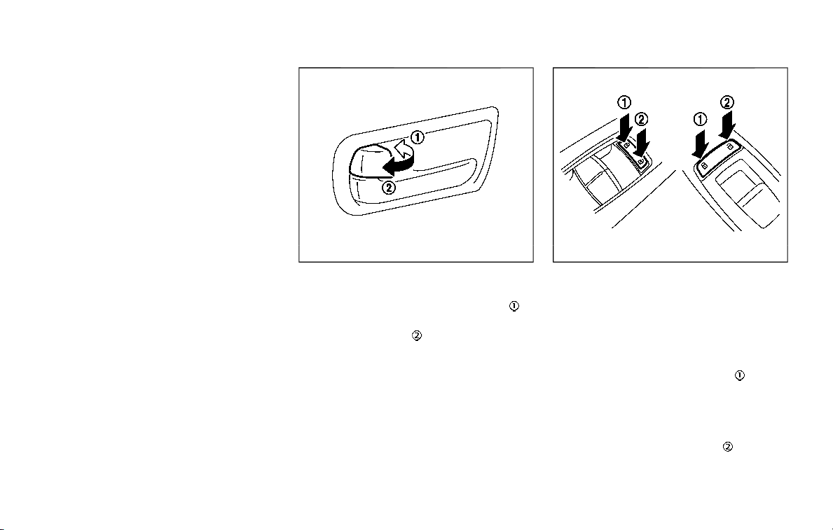
(See NissanConnect® Owner’s Man-
ual.)
OPENING AND CLOSING WINDOWS
WITH THE MECHANICAL KEY
The driver’s door key operation also
allows you to open and close all door
windows.
To open the windows, turn the driver’s
door key cylinder to the rear of the vehicle
for longer than 1 second. The door is
unlocked and the window keeps opening
while turning the key.
This function can also be performed by
pushing and holding the door UNLOCK
button of the Intelligent Key. (See “Re-
mote keyless entry system” (P.3-15).)
To close the windows, turn the driver’s
door key cylinder to the front of the
vehicle for longer than 1 second. The
door is locked and the window keeps
closing while turning the key.
SPA2744
LOCKING WITH INSIDE LOCK KNOB
To lock the door individually, move the
inside lock knob to the lock position
.
To unlock, move the inside lock knob to
the unlock position
.
Be sure not to leave the Intelligent Key
inside the vehicle.
JVP0319X
LOCKING WITH POWER DOOR LOCK
SWITCH
Operating the power door lock switch will
lock or unlock all the doors. The switches
are located on the driver’s and front
passenger’s door armrests.
To lock the doors, push the power door
lock switch to the lock position
.
Be sure not to leave the Intelligent Key
inside the vehicle.
To unlock the doors including the fuel-
filler door, push the power door lock
switch to the unlock position
.
Pre-driving checks and adjustments 3-5
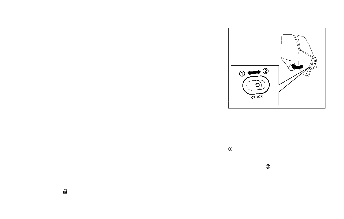
3-6 Pre-driving checks and adjustments
Lockout protection
When the power door lock switch (driver
or front passenger) is moved to the lock
position with any door open, all doors will
lock and unlock automatically. With the
Intelligent Key left in the vehicle and any
door open, all doors will unlock automa-
tically and a chime will sound after the
door is closed.
These functions help to prevent the
Intelligent Key from being accidentally
locked inside the vehicle.
AUTOMATIC DOOR LOCKS
. All doors lock automatically when the
vehicle speed reaches 15 MPH (24
km/h).
. All doors unlock automatically when
the ignition switch is placed in the OFF
position.
The automatic unlock function can be
deactivated or activated. To deactivate
or activate the automatic door unlock
system, perform the following procedure:
1. Close all doors.
2. Place the ignition switch in the ON
position.
3. Within 20 seconds of performing Step
2, push and hold the power door lock
switch to the
position (UNLOCK)
for more than 5 seconds.
4. When activated, the hazard indicator
will flash twice. When deactivated, the
hazard indicator will flash once.
5. The ignition switch must be placed in
the OFF and ON position again be-
tween each setting change.
When the automatic door unlock system
is deactivated, the doors do not unlock
when the ignition switch is placed in the
OFF position. To unlock the door manu-
ally, use the inside lock knob or the power
door lock switch (driver’s or front passen-
ger’s side).
SPA2745
CHILD SAFETY REAR DOOR LOCK
Child safety rear door locks help prevent
doors from being opened accidentally,
especially when small children are in the
vehicle.
When the levers are in the lock position
, the rear doors can be opened only
from the outside.
To disengage, move the levers to the
unlock position
.

WARNING
. Radio waves could adversely af-
fect electric medical equipment.
Those who use a pacemaker
should contact the electric med-
ical equipment manufacturer for
the possible influences before
use.
. The Intelligent Key transmits
radio waves when the buttons
are pushed. The FAA advises that
the radio waves may affect air-
craft navigation and communica-
tion systems. Do not operate the
Intelligent Key while on an air-
plane. Make sure the buttons are
not operated unintentionally
when the unit is stored during a
flight.
The Intelligent Key system can operate all
the door locks using the remote control-
ler function or pushing the request switch
on the vehicle without taking the key out
from a pocket or purse. The operating
environment and/or conditions may af-
fect the Intelligent Key system operation.
Be sure to read the following before using
the Intelligent Key system.
CAUTION
. Be sure to carry the Intelligent
Key with you when operating the
vehicle.
. Never leave the Intelligent Key in
the vehicle when you leave the
vehicle.
The Intelligent Key is always communi-
cating with the vehicle as it receives radio
waves. The Intelligent Key system trans-
mits weak radio waves. Environmental
conditions may interfere with the opera-
tion of the Intelligent Key system under
the following operating conditions.
. When operating near a location where
strong radio waves are transmitted,
such as a TV tower, power station and
broadcasting station.
. When in possession of wireless equip-
ment, such as a cellular telephone,
transceiver, and CB radio.
. When the Intelligent Key is in contact
with or covered by metallic materials.
. When any type of radio wave remote
control is used nearby.
. When the Intelligent Key is placed near
an electric appliance such as a perso-
nal computer.
. When the vehicle is parked near a
parking meter.
In such cases, correct the operating
conditions before using the Intelligent
Key function or use the mechanical key.
Although the life of the battery varies
depending on the operating conditions,
the battery’s life is approximately 2 years.
If the battery is discharged, replace it with
a new one.
Since the Intelligent Key is continuously
receiving radio waves, if the key is left
near equipment which transmits strong
radio waves, such as signals from a TV
and personal computer, the battery life
may become shorter.
For information regarding replacement of
a battery, see “Intelligent Key battery
replacement” (P.8-21).
As many as 4 Intelligent Keys can be
registered and used with one vehicle. For
information about the purchase and use
of additional Intelligent Keys, contact a
NISSAN dealer.
CAUTION
. Do not allow the Intelligent Key,
which contains electrical compo-
nents, to come into contact with
water or salt water. This could
Pre-driving checks and adjustments 3-7
INTELLIGENT KEY SYSTEM

3-8 Pre-driving checks and adjustments
affect the system function.
. Do not drop the Intelligent Key.
. Do not strike the Intelligent Key
sharply against another object.
. Do not change or modify the
Intelligent Key.
. Wetting may damage the Intelli-
gent Key. If the Intelligent Key
gets wet, immediately wipe until
it is completely dry.
. If the outside temperature is be-
low 14°F (−10°C), the battery of the
Intelligent Key may not function
properly.
. Do not place the Intelligent Key
for an extended period in an area
where temperatures exceed
140°F (60°C).
. Do not attach the Intelligent Key
with a key holder that contains a
magnet.
. Do not place the Intelligent Key
near equipment that produces a
magnetic field, such as a TV,
audio equipment and personal
computers.
If an Intelligent Key is lost or stolen,
NISSAN recommends erasing the ID code
of that Intelligent Key from the vehicle.
This may prevent the unauthorized use of
the Intelligent Key to operate the vehicle.
For information regarding the erasing
procedure, it is recommended that you
contact a NISSAN dealer.
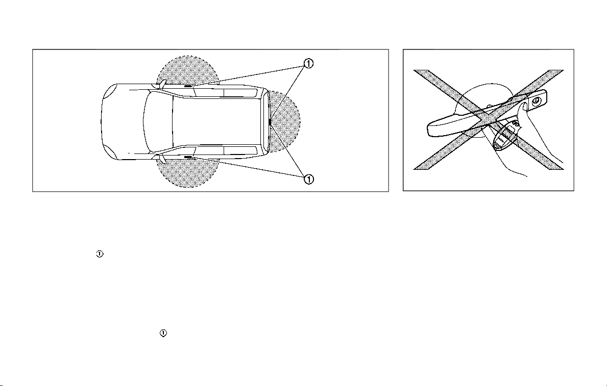
SPA2074
INTELLIGENT KEY OPERATING
RANGE
The Intelligent Key functions can only be
used when the Intelligent Key is within
the specified operating range from the
request switch
.
When the Intelligent Key battery is dis-
charged or strong radio waves are pre-
sent near the operating location, the
Intelligent Key system’s operating range
becomes narrower, and the Intelligent
Key may not function properly.
The operating range is within 31.50 in (80
cm) from each request switch
.
If the Intelligent Key is too close to the
door glass, handle or rear bumper the
request switches may not function.
When the Intelligent Key is within the
operating range, it is possible for anyone
who does not carry the Intelligent Key to
push the request switch to lock/unlock
the doors.
SPA2326
DOOR LOCKS/UNLOCKS PRECAU-
TION
. Do not push the door handle request
switch with the Intelligent Key held in
your hand as illustrated. The close
distance to the door handle will cause
the Intelligent Key system to have
difficulty recognizing that the Intelli-
gent Key is outside the vehicle.
. After locking with the door handle
request switch, verify the doors are
securely locked by testing them.
. To prevent the Intelligent Key from
being left inside the vehicle, make sure
you carry the key with you and then
lock the doors.
Pre-driving checks and adjustments 3-9
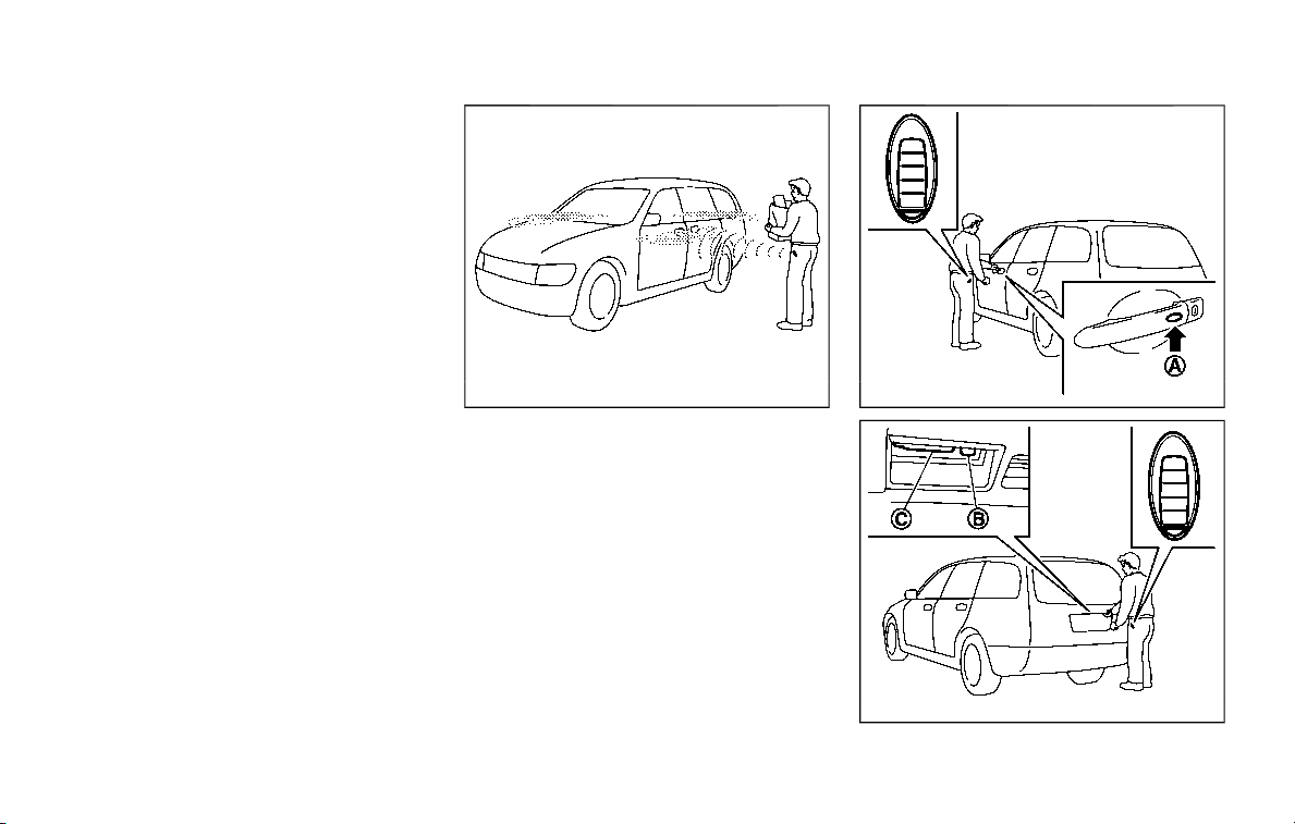
3-10 Pre-driving checks and adjustments
. Do not pull the door handle before
pushing the door handle request
switch. The door will be unlocked but
will not open. Release the door handle
once and pull it again to open the
door.
. The Intelligent Key system (opening/
closing doors with the door handle
request switch) can be set to remain
inactive. (See NissanConnect® Owner’s
Manual.)
. While the liftgate is in motion by using
the power liftgate button on the
Intelligent Key, the request switches
on the door handles may be disabled.
To unlock or lock the doors, use the
UNLOCK or LOCK button on the In-
telligent Key. See “How to use remote
keyless entry system” (P.3-16).
SPA2408
INTELLIGENT KEY OPERATION
You can lock or unlock the doors without
taking the key out from your pocket or
bag.
JVP0196X
JVP0197X

When you carry the Intelligent Key with
you, you can lock or unlock all doors by
pushing the door handle request switch
(driver’s or front passenger’s)
or the
liftgate request switch
within the range
of operation.
When you lock or unlock the doors or the
liftgate, the hazard indicator will flash and
the horn (or the outside chime) will sound
as a confirmation. For details, see “Setting
hazard indicator and horn mode” (P.3-17).
Welcome light and farewell light
function
When you lock or unlock the doors
including the liftgate, the parking lights,
tail lights, side marker light and the
license plate light will illuminate for a
period of time. The welcome light and
farewell light function can be disabled.
For information about disabling the wel-
come light and farewell light function, it is
recommended you see a NISSAN dealer.
Locking doors and fuel-filler door
1. Move the shift lever to the P (Park)
position, push the ignition switch to
the OFF position and make sure you
carry the Intelligent Key with you.*1
2. Close all the doors.*2
3. Push the door handle request switch
(driver’s or front passenger’s)
or the
liftgate request switch
while carry-
ing the Intelligent Key with you.*3
4. All the doors and fuel-filler door will
lock.
5. The hazard indicator flashes twice
and the outside chime sounds twice.
*1: Doors will lock with the Intelligent Key
while the ignition switch is in the ACC or
ON position.
*2: Doors will not lock with the Intelligent
Key while any door is open.
*3: Doors will not lock by pushing the door
handle request switch with the Intelligent
Key inside the vehicle.
However, when an Intelligent Key is inside
the vehicle, doors can be locked with
another registered Intelligent Key.
CAUTION
. After locking the doors using the
request switch, make sure that
the doors have been securely
locked by operating the door
handles.
. When locking the doors using the
request switch, make sure to
have the Intelligent Key in your
possession before operating the
request switch to prevent the
Intelligent Key from being left in
the vehicle.
. The request switch is operational
only when the Intelligent Key has
been detected by the Intelligent
Key system.
Lockout protection:
To prevent the Intelligent Key from being
accidentally locked in the vehicle, lockout
protection is equipped with the Intelligent
Key system.
When the driver’s side door is open, the
doors are locked, and then the Intelligent
Key is put inside the vehicle and all the
doors are closed; the lock will automati-
cally unlock and the door buzzer sounds.
NOTE:
The doors may not lock when the
Intelligent Key is in the same hand that
is operating the request switch to lock
the door. Put the Intelligent Key in a
purse, pocket or your other hand.
Pre-driving checks and adjustments 3-11

3-12 Pre-driving checks and adjustments
CAUTION
The lockout protection may not
function under the following condi-
tions:
. When the Intelligent Key is placed
on top of the instrument panel.
. When the Intelligent Key is placed
inside the glove box or a storage
bin.
. When the Intelligent Key is placed
inside the door pockets.
. When the Intelligent Key is placed
inside or near metallic materials.
Unlocking doors and fuel-filler door
1. Push the door handle request switch
(driver’s or front passenger’s)
or the
liftgate request switch
once while
carrying the Intelligent Key with you.
When you approach the vehicle with
the Intelligent Key, the puddle light
and the passenger cabin illumination
will illuminate and stay on for a short
period of time (if so equipped). (See
“Welcome light” (P.2-67).)
2. The hazard indicator flashes once and
outside chime sounds once. The cor-
responding door will unlock.
The fuel-filler door will also unlock
when the driver’s door handle request
switch is pushed.
3. Push the door handle request switch
again within 60 seconds.
4. The hazard indicator flashes once and
outside chime sounds once again. All
the doors will unlock.
The liftgate can be unlocked and opened
by pushing the liftgate opener switch. See
“Liftgate” (P.3-22).
All doors will be locked automatically
unless one of the following operations is
performed within 1 minute after pushing
the request switch while the doors are
locked. If during this 1-minute time period,
the request switch is pushed, all doors will
be locked automatically after another 1
minute.
. Opening any door
. Pushing the ignition switch
Power liftgate open (if so equipped)
1. Carry the Intelligent Key.
2. Push the power liftgate opener switch
.
3. The liftgate will unlock and automati-
cally open.
4. The hazard indicator flashes 4 times
and the outside chime sounds.
BATTERY SAVER SYSTEM
When all the following conditions are met
for a period of time, the battery saver
system will cut off the power supply to
prevent battery discharge.
. The ignition switch is in the ACC
position, and
. All doors are closed, and
. The shift lever is in the P (Park)
position.
WARNING SIGNALS
To help prevent the vehicle from moving
unexpectedly by erroneous operation of
the Intelligent Key listed on the following
chart or to help prevent the vehicle from
being stolen, chime or beep sounds inside
and outside the vehicle and a warning
displays in the vehicle information display.
When a chime or beep sounds or the
warning displays, be sure to check the
vehicle and Intelligent Key.
See “Troubleshooting guide” (P.3-13) and
“Vehicle information display” (P.2-20).

TROUBLESHOOTING GUIDE
Symptom Possible cause
Action to take
When pushing the ignition
switch to stop the engine
The SHIFT P warning appears on the
display and the inside warning chime
sounds continuously or for a few sec-
onds.
The shift lever is not in the P (Park)
position.
Shift the shift lever to the P (Park)
position.
When shifting the shift lever
to the P (Park) position.
The inside warning chime sounds con-
tinuously.
The ignition switch is in the ACC or
ON position.
Push the ignition switch to the OFF
position.
When opening the driver’s
door to get out of the vehicle
The inside warning chime sounds con-
tinuously.
The ignition switch is in the ACC
position.
Push the ignition switch to the OFF
position.
When closing the door after
getting out of the vehicle
The NO KEY warning appears on the
display, the outside chime sounds 3
times and the inside warning chime
sounds for a few seconds.
The ignition switch is in the ACC or
ON position.
Push the ignition switch to the OFF
position.
The “REAR DOOR ALERT IS ACTIVATED”
message appears on the display, the
horn sounds three times twice and
“CHECK BACK SEAT FOR ALL ARTICLES”
warning appears on the display.
The rear door alert is activated.
Open a rear door and check the rear
seat for all articles to clear the warn-
ing message.
The SHIFT P warning appears on the
display and the outside chime sounds
continuously.
The ignition switch is in the ACC or
OFF position and the shift lever is
not in the P (Park) position.
Move the shift lever to the P (Park)
position and push the ignition switch
to the OFF position.
When closing the door with
the inside lock knob turned
to LOCK
The outside chime sounds for a few
seconds and all the doors unlock.
The Intelligent Key is inside the
vehicle or cargo area.
Carry the Intelligent Key with you.
When pushing the request
switch or the LOCK
but-
ton on the Intelligent Key to
lock the door
The outside chime sounds for a few
seconds.
The Intelligent Key is inside the
vehicle.
Carry the Intelligent Key with you.
A door is not closed securely.
Close the door securely.
Pre-driving checks and adjustments 3-13

3-14 Pre-driving checks and adjustments
Symptom Possible cause
Action to take
When pushing the door han-
dle request switch to lock the
door
The outside chime sounds for a few
seconds.
The Intelligent Key is inside the
vehicle or cargo area.
Carry the Intelligent Key with you.
A door is not closed securely.
Close the door securely.
The door handle request switch is
pushed before the door is closed.
Push the door handle request switch
after the door is closed.
When pushing the ignition
switch to start the engine
The Intelligent Key battery indicator
appears on the display.
The battery charge is low.
Replace the battery with a new one.
(See “Battery” (P.8-11).)
The NO KEY warning appears on the
display and the inside warning chime
sounds for a few seconds.
The Intelligent Key is not in the
vehicle.
Carry the Intelligent Key with you.
When pushing the ignition
switch
The Intelligent Key system warning light
in the meter illuminates in yellow.
It warns of a malfunction with the
Intelligent Key system.
It is recommended that you contact a
NISSAN dealer.
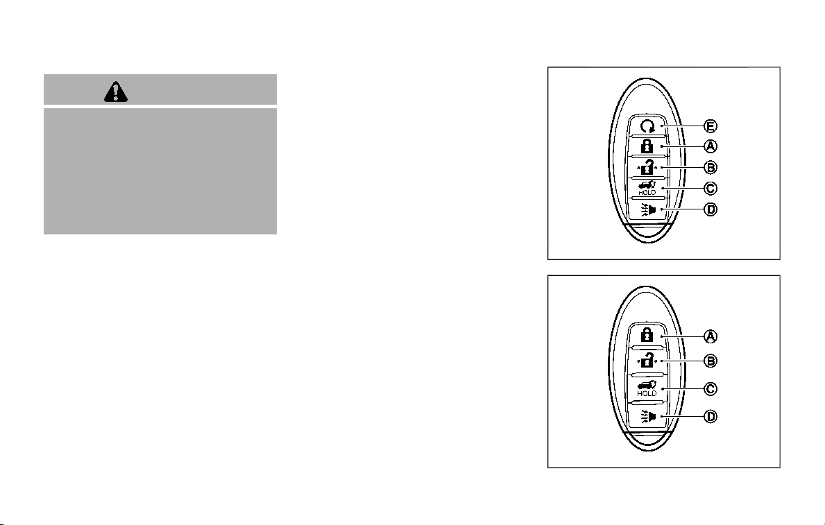
WARNING
The Intelligent Key transmits radio
waves when the buttons are pushed.
The FAA advises that radio waves
may affect aircraft navigation and
communication systems. Do not op-
erate the Intelligent Key while on an
airplane. Make sure the buttons are
not operated unintentionally when
the unit is stored for a flight.
It is possible to lock/unlock all doors, fuel-
filler door, activate the panic alarm and
open the windows by pushing the but-
tons on the Intelligent Key from outside
the vehicle.
Before locking the doors, make sure the
Intelligent Key is not left in the vehicle.
The LOCK/UNLOCK button on the Intelli-
gent Key can operate at a distance of
approximately 33 ft (10 m) from the
vehicle. (The effective distance depends
upon the conditions around the vehicle.)
As many as 4 Intelligent Keys can be used
with one vehicle. For information con-
cerning the purchase and use of addi-
tional Intelligent Keys, contact a NISSAN
dealer.
The lock and unlock buttons on the
Intelligent Key will not operate when:
. the distance between the Intelligent
Key and the vehicle is over 33 ft (10 m).
. the Intelligent Key battery runs down.
After locking with the remote keyless
entry function, pull the door handle to
make sure the doors are securely locked.
The LOCK/UNLOCK operating range var-
ies depending on the environment. To
securely operate the lock and unlock
buttons, approach the vehicle to about 3
ft (1 m) from the door.
JVP0156X
Type A (if so equipped)
SPA2718
Type B (if so equipped)
Pre-driving checks and adjustments 3-15
REMOTE KEYLESS ENTRY SYSTEM
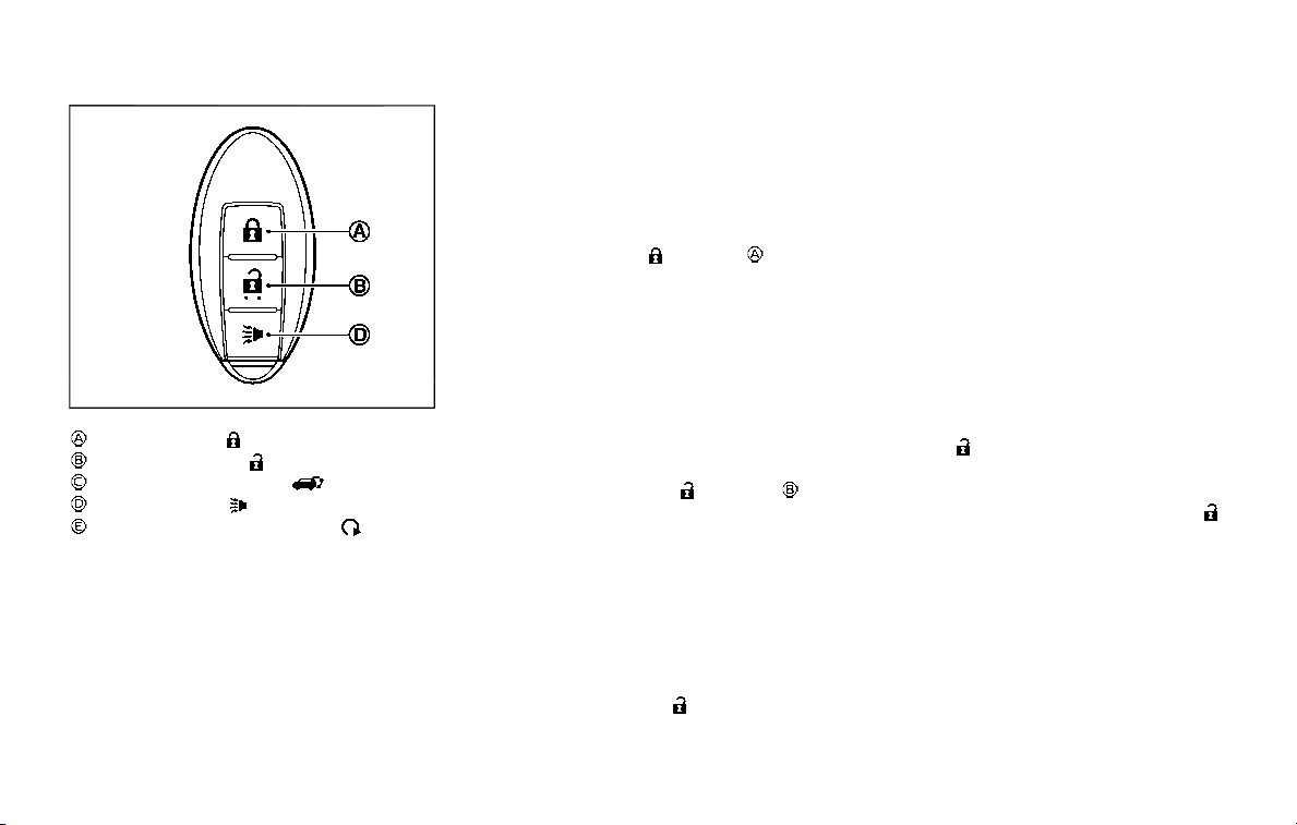
3-16 Pre-driving checks and adjustments
SPA1926B
Type C (if so equipped)
LOCK button
UNLOCK button
Power liftgate button
PANIC button
Remote engine start button
HOW TO USE REMOTE KEYLESS
ENTRY SYSTEM
When you lock or unlock the doors or the
liftgate, the hazard indicator will flash and
the horn (or the outside chime) will sound
as a confirmation. For details, see “Setting
hazard indicator and horn mode” (P.3-17).
Locking doors and fuel-filler door
1. Move the shift lever to the P (Park)
position, push the ignition switch to
the OFF position and make sure you
carry the Intelligent Key with you.*
2. Close all the doors and the liftgate.
3. Push the LOCK
button on the
Intelligent Key.
4. All the doors, the liftgate and fuel-filler
door will lock.
5. The hazard indicator flashes twice
and the horn chirps once.
*: Doors will lock with the Intelligent Key
while the ignition switch is in the ACC or
ON position.
Unlocking doors and fuel-filler door
1. Push the UNLOCK button on
the Intelligent Key once.
2. The hazard indicator flashes once. The
driver’s door and fuel-filler door will
unlock.
The puddle light and the passenger
cabin illumination will illuminate and
stay on for a short period of time (if so
equipped). (See “Welcome light” (P.2-
67).)
3. Push the UNLOCK
button on the
Intelligent Key again within 60 sec-
onds.
4. The hazard indicator flashes once
again. All the doors will unlock.
All doors will be locked automatically
unless one of the following operations is
performed within 1 minute after pushing
the UNLOCK button on the Intelligent Key
while the doors are locked. If during this 1-
minute time period, the UNLOCK button
on the Intelligent Key is pushed, all doors
will be locked automatically after another
1 minute.
. Opening any door
. Pushing the ignition switch
Opening windows
To open the windows, push the door
UNLOCK
button on the Intelligent
Key for about 3 seconds after the door is
unlocked.
To stop opening, release the UNLOCK
button.
Window cannot be closed using the
Intelligent Key.
The door windows can be opened or
closed by turning the mechanical key in
a door lock. (See “Doors” (P.3-4).)

Opening/closing liftgate (if so
equipped)
1. Push the power liftgate button
for more than 1 second.
2. The liftgate will automatically open.
The hazard indicator flashes 4 times and
the outside chime sounds for approxi-
mately 3 seconds.
To close the liftgate, push the power
liftgate button
for more than 1
second.
The liftgate will automatically close.
If the button
is pushed while the
liftgate is being opened or closed, the
liftgate will reverse.
Using panic alarm
If you are near your vehicle and feel
threatened, you may activate the alarm
to call attention as follows:
1. Push the PANIC
button on the
Intelligent Key for more than 1 sec-
ond.
2. The theft warning alarm and head-
lights will stay on for 25 seconds.
3. The panic alarm stops when:
.
It has run for 25 seconds, or
.
Any of the buttons on the Intelligent
Key are pushed. (Note: Panic button
or power liftgate button should be
pushed for more than 1 second.)
Remote engine start (if so
equipped)
The remote engine start button is
on the Intelligent Key if the vehicle has
remote engine start function. This func-
tion allows the engine to start from
outside the vehicle. See “Remote engine
start” (P.3-19) for more details.
Setting hazard indicator and horn
mode
This vehicle is set in hazard indicator and
horn mode when you first receive the
vehicle.
In hazard indicator and horn mode, when
the LOCK
button is pushed, the
hazard indicator flashes twice and the
horn chirps once. When the UNLOCK
button is pushed, the hazard indicator
flashes once.
If horns are not necessary, the system
can be switched to the hazard indicator
mode.
In hazard indicator mode, when the LOCK
button is pushed, the hazard indica-
tor flashes twice. When the UNLOCK
button is pushed, neither the hazard
indicator nor the horn operates.
Pre-driving checks and adjustments 3-17
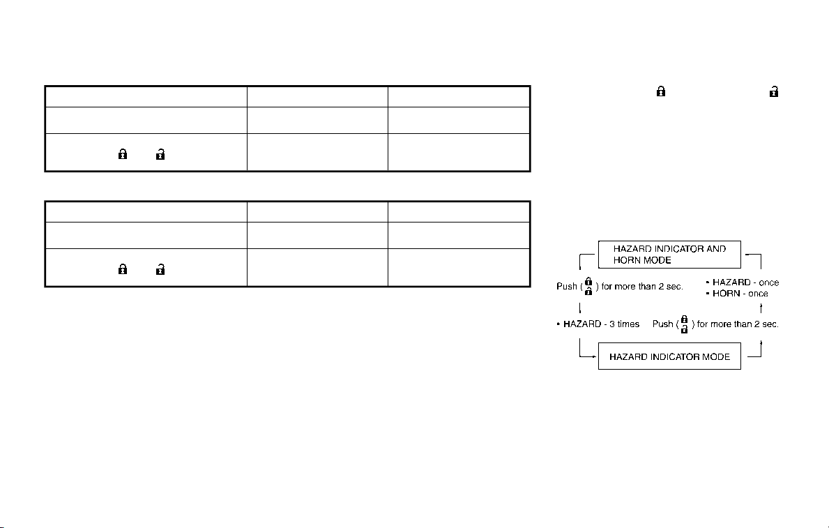
3-18 Pre-driving checks and adjustments
Hazard indicator and horn mode:
DOOR LOCK
DOOR UNLOCK
Intelligent Key system
(Using door handle request switch)
HAZARD - twice
OUTSIDE CHIME - twice
HAZARD - once
OUTSIDE CHIME - once
Remote keyless entry system
(Using
or button)
HAZARD - twice
HORN - once
HAZARD - once
HORN - none
Hazard indicator mode:
DOOR LOCK
DOOR UNLOCK
Intelligent Key system
(Using door handle request switch)
HAZARD - twice
HAZARD - none
Remote keyless entry system
(Using
or button) HAZARD - twice
HAZARD - none
Switching procedure:
Push the LOCK
and UNLOCK
buttons on the Intelligent Key simulta-
neously for more than 2 seconds to
switch the mode from one to the other.
When pushing the buttons to set the
hazard indicator mode, the hazard indi-
cator flashes 3 times.
When pushing the buttons to set the
hazard indicator and horn mode, the
hazard indicator flashes once and the
horn chirps once.
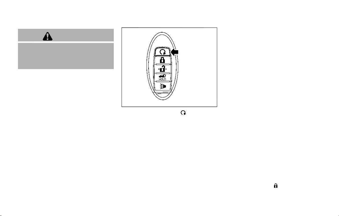
WARNING
To avoid risk of injury or death, do
not use the remote engine start
function when the vehicle is in an
enclosed area such as a garage.
JVP0445X
The remote engine start
button is on
the Intelligent Key if the vehicle has
remote engine start function. This func-
tion allows the engine to start from
outside the vehicle.
Some systems, such as the air conditioner
system, will turn on during a remote
engine start, if the system was on the
last time the ignition switch was turned
off.
Laws in some local communities may
restrict the use of remote engine starters.
For example, some laws require a person
using remote engine start to have the
vehicle in view. Check local regulations for
any requirements.
Other conditions may affect the remote
engine start function. See “Conditions the
remote engine start will not work” (P.3-
20).
Other conditions can affect the perfor-
mance of the Intelligent Key transmitter.
See “Intelligent Key system” (P.3-7) for
additional information.
REMOTE ENGINE START OPERATING
RANGE
The remote engine start function can
only be used when the Intelligent Key is
within the specified operating range from
the vehicle.
When the Intelligent Key battery is dis-
charged or other strong radio wave
sources are present near the operating
location, the Intelligent Key operating
range becomes narrower, and the Intelli-
gent Key may not function properly.
The remote engine start operating range
is approximately 197 ft (60 m) from the
vehicle.
REMOTE STARTING THE ENGINE
To use the remote start function to start
the engine, perform the following:
1. Aim the Intelligent Key at the vehicle.
2. Push the “LOCK”
button to lock all
doors.
Pre-driving checks and adjustments 3-19
REMOTE ENGINE START (if so equipped)

3-20 Pre-driving checks and adjustments
3. Within 5 seconds push and hold the
remote engine start
button until
the turn signal lights flash and the tail
lights illuminate. If the vehicle is not
within view, push and hold the remote
engine start
button for at least 2
seconds.
The following events will occur when the
engine starts:
. The front parking lights will turn on
and remain on as long as the engine is
running.
. The doors will be locked and the air
conditioner system may turn on.
. The engine will continue to run for
about 10 minutes. Repeat the steps to
extend the time for an additional 10
minutes. See “Extending engine run
time” (P.3-20).
Depress and hold the brake pedal, then
place the ignition switch in the ON posi-
tion before driving. For further instruc-
tions, see “Driving the vehicle” (P.5-17).
EXTENDING ENGINE RUN TIME
The remote engine start function can be
extended one time by performing the
steps listed in “Remote starting the en-
gine” (P.3-19). Run time will be calculated
as follows:
. The first 10 minute run time will start
when the remote engine start func-
tion is performed.
. The second 10 minutes will start im-
mediately when the remote engine
start function is performed. For exam-
ple, if the engine has been running for
5 minutes, and 10 minutes are added,
the engine will run for a total of 15
minutes.
. Extending engine run time will count
towards the two remote engine start
limit.
A maximum of two remote engine starts,
or a single start with an extension, are
allowed between ignition cycles.
The ignition switch must be cycled to the
ON position and then back to the OFF
position before the remote engine start
procedure can be used again.
CANCELING A REMOTE ENGINE
START
To cancel a remote engine start, perform
one of the following:
. Aim the Intelligent Key at the vehicle
and push and hold the remote engine
start
button until the front park-
ing lights turn off.
. Turn on the hazard indicator flashers.
. Cycle the ignition switch ON and then
OFF.
. The extended engine run time has
expired.
. The first 10 minute timer has expired.
. The engine hood has been opened.
. The shift lever is moved out of the P
(Park) position.
. The theft alarm sounds due to illegal
entry into the vehicle.
. The ignition switch is pushed without
an Intelligent Key in the vehicle.
. The ignition switch is pushed with an
Intelligent Key in the vehicle but the
brake pedal is not depressed.
CONDITIONS THE REMOTE ENGINE
START WILL NOT WORK
The remote engine start will not operate
if any of the following conditions are
present:
. The ignition switch is placed in the ON
position.
. The hood is not securely closed.
. The hazard indicator flashers are on.
. The engine is still running. The engine
must be completely stopped. Wait at
least 6 seconds if the engine goes
from running to off. This is not applic-
able when extending engine run time.
. The remote engine start
button is
not pushed and held for at least 2
seconds.
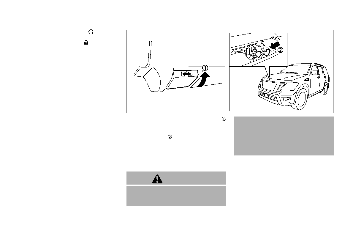
. The remote engine start button is
not pushed and held within 5 seconds
of pushing the “LOCK”
button.
. The brake pedal is depressed.
. The doors are not closed and locked.
. The liftgate is open.
. The Intelligent Key system warning
light remains on in the vehicle infor-
mation display.
. An Intelligent Key is left inside the
vehicle.
. The theft alarm sounds due to illegal
entry into the vehicle.
. Two remote engine starts, or a single
remote engine start with an exten-
sion, have already been used.
. The shift lever is not in the P (Park)
position.
The remote engine start may display a
warning or indicator in the vehicle infor-
mation display. For an explanation of the
warning or indicator, see “Operational
indicators” (P.2-23).
JVP0463X
1. Pull the hood lock release handle
located below the instrument panel;
the hood will then spring up slightly.
2. Pull the lever
up at the front of the
hood with your fingertips and raise
the hood.
3. When closing the hood, slowly close
the hood down and make sure it locks
into place.
WARNING
. Make sure the hood is completely
closed and latched before driving.
Failure to do so could cause the
hood to fly open and result in an
accident.
. If you see steam or smoke com-
ing from the engine compart-
ment, to avoid injury do not
open the hood.
Pre-driving checks and adjustments 3-21
HOOD
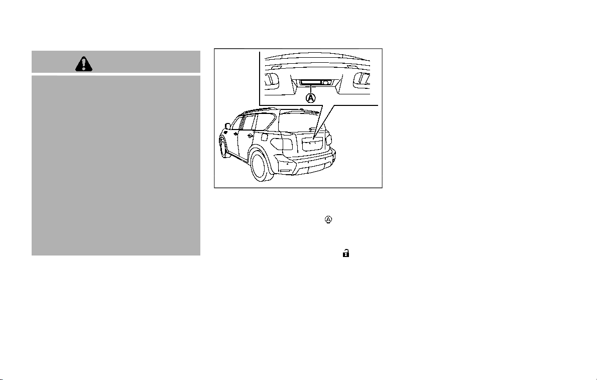
3-22 Pre-driving checks and adjustments
WARNING
. Always be sure the liftgate has
been closed securely to prevent it
from opening while driving.
. Do not drive with the liftgate
open. This could allow dangerous
exhaust gases to be drawn into
the vehicle. See “Exhaust gas
(carbon monoxide)” (P.5-4).
. Do not leave children unattended
inside the vehicle. They could
unknowingly activate switches
or controls. Unattended children
could become involved in serious
accidents.
. Always be sure that hands and
feet are clear of the door frame to
avoid injury while closing the
liftgate.
JVP0464X
OPERATING MANUAL LIFTGATE
To open the liftgate, unlock it and push
the liftgate opener switch
. Pull up the
liftgate to open.
The liftgate can be unlocked by:
. pushing the unlock button
on the
Intelligent Key twice.
. pushing the liftgate request switch
with the Intelligent Key carried on you.
. pushing the door handle request
switch twice with the Intelligent Key
carried on you.
. pushing the power door lock switch to
the unlock position.
. inserting the mechanical key into the
driver’s door key cylinder and turning
it to the rear of the vehicle twice.
To close the liftgate, pull down until it
securely locks.
OPERATING POWER LIFTGATE (if so
equipped)
To operate the power liftgate, the shift
lever must be in the P (Park) position.
The power liftgate will not operate if the
battery voltage is low.
LIFTGATE

SPA2547
Power liftgate main switch
The power liftgate operation can be
turned on or off by the power liftgate
main switch on the instrument panel.
When the power liftgate main switch is
pushed to the “OFF” position, the power
operation is not available by the power
liftgate switch on the liftgate and liftgate
opener switch.
The liftgate can still be operated by the
power liftgate switch on the instrument
panel and the power liftgate button on
the Intelligent Key.
SPA2548
Power liftgate switch — Instrument panel
JVP0465X
Liftgate opener switch
JVP0214X
Intelligent Key
SPA2796
Power liftgate switch — Liftgate
Pre-driving checks and adjustments 3-23
3-24 Pre-driving checks and adjustments
Power open
When the liftgate is fully closed, the
liftgate will fully open automatically by:
. pushing the power liftgate switch
on the instrument panel
. pushing the liftgate opener switch
. pushing the power liftgate button
on the Intelligent Key for more than 1
second
The hazard flashes 4 times and the out-
side chime sounds when the liftgate
starts opening.
NOTE:
The liftgate can be opened by the
power liftgate switch
, the liftgate
opener switch
or the power liftgate
button
even if the liftgate is
locked. The liftgate will individually un-
lock and open.
Power close
When the liftgate is fully opened, the
liftgate will fully close automatically by:
. pushing the power liftgate switch
on the instrument panel
. pushing the power liftgate button
on the Intelligent Key for more than 1
second
. pushing the power liftgate switch
on the lower part of the liftgate
The hazard flashes 4 times and the out-
side chime sounds when the liftgate
starts closing.
NOTE:
When the liftgate is closed, it remains
unlocked. Manually lock the liftgate.
Reverse function
The power liftgate will reverse immedi-
ately if one of the following actions is
performed during power open or power
close.
. pushing the power liftgate switch
on the instrument panel
. pushing the power liftgate button
on the Intelligent Key.
. pushing the liftgate switch
on the
lower part of the liftgate
The outside chime sounds when the
liftgate starts to reverse.
Auto reverse function
The auto-reverse function enables the
liftgate to automatically reverse when
something is caught in the liftgate as it
is opening or closing. When the control
unit detects an obstacle, the liftgate will
reverse and return to the full open or full
close position.
If a second obstacle is detected, the
liftgate motion will stop and the drive
motor will disengage. The liftgate will
enter the manual mode.
A pinch sensor is mounted on each side
of the liftgate. If an obstacle is detected
by the pinch sensor during power close,
the liftgate will reverse and return to the
full open position immediately.
NOTE:
If the pinch sensor is damaged or
removed, the power close function will
not operate.
WARNING
There is a small distance immedi-
ately before the closed position that
cannot be detected. Make sure that
all passengers keep their hands, etc.,
clear from the liftgate opening be-
fore closing the liftgate.
Manual mode
If power operation is not available, the
liftgate can be operated manually. Power
operation may not be available if multiple
obstacles have been detected in a single
power cycle or if the battery voltage is
low. When the power liftgate main switch
is in the OFF position, the liftgate can be
opened manually by pushing the liftgate
opener switch. If the power liftgate open-
er switch is pushed during power open or
close, the power operation will be can-
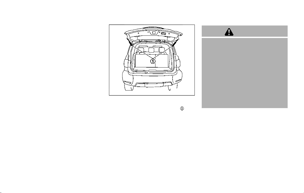
celed and the liftgate can be operated
manually.
JVP0466X
Safe Mode
If the gas stays of the liftgate lose
pressure, the power liftgate safe mode is
activated. When the safe mode is acti-
vated, the liftgate intermittently closes.
Then the liftgate will be pulled to the
closed and latched position by a motor.
The power liftgate cannot be opened
using the switches at any time in the safe
mode.
Do not operate the liftgate again until it is
checked. It is recommended you visit a
NISSAN dealer for this service.
CAUTION
. If the power liftgate does not stay
open or if the liftgate unexpect-
edly closes at any time, do not
operate the liftgate. There may
be a pressure loss in one or both
of the liftgate gas stays. Have the
liftgate inspected. It is recom-
mended you visit a NISSAN dealer
for this service.
. Do not activate the power liftgate
if one or both of the liftgate gas
stays are removed. Damage to
the liftgate or power liftgate me-
chanisms may occur.
AUTO CLOSURE
If the liftgate is pulled down to a partly
open position, the liftgate will pull itself to
the closed position.
Do not apply excessive force when the
auto closure is operating. Excessive
force applied may cause the mechan-
ism to malfunction.
Pre-driving checks and adjustments 3-25
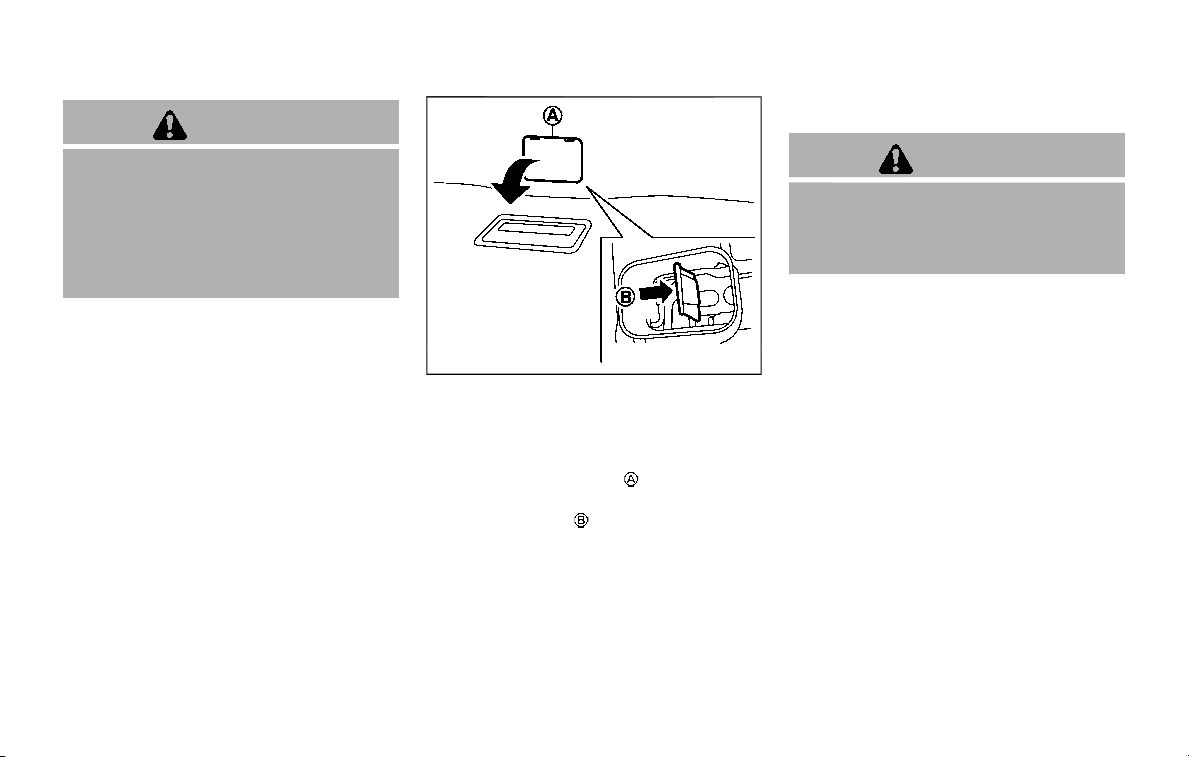
3-26 Pre-driving checks and adjustments
CAUTION
. The liftgate will automatically
close from a partly open position.
To avoid pinching, keep hands
and fingers away from liftgate
opening.
. Do not let children operate the
liftgate.
SPA2751
LIFTGATE RELEASE LEVER
If the liftgate cannot be opened with the
door lock switch due to a discharged
battery, follow these steps.
1. Remove the cover
inside of the
liftgate using a suitable tool.
2. Move the lever
as illustrated to open
the liftgate.
It is recommended you contact a NISSAN
dealer as soon as possible for repair.
OPENING THE FUEL-FILLER DOOR
CAUTION
Lock all doors before going through
automatic car wash. Locking doors
helps prevent fuel-filler door from
opening and becoming damaged.
FUEL-FILLER DOOR
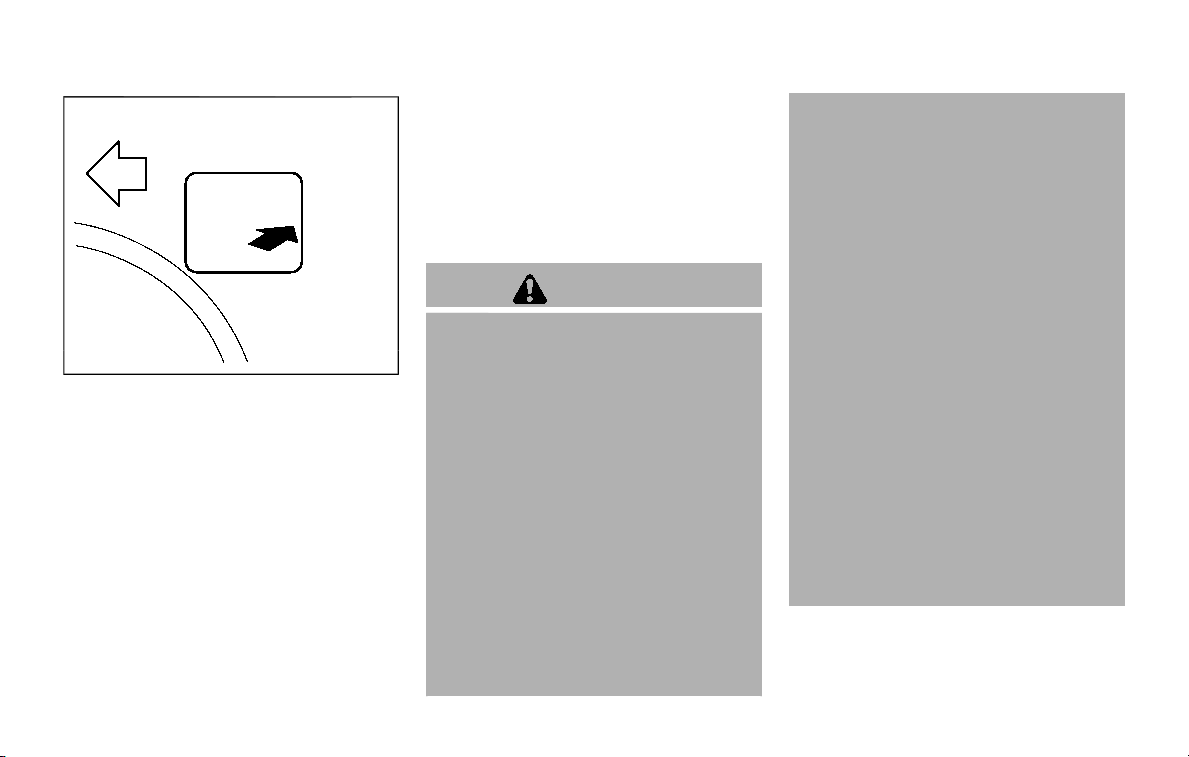
SPA2752
To open the fuel-filler door, unlock the
fuel-filler door by using one of the follow-
ing operations, then push the right side of
the door.
. Push the driver’s door handle request
switch with the Intelligent Key carried
with you.
. Push the passenger’s door handle
request switch or liftgate request
switch twice with the Intelligent Key
carried with you.
. Push the UNLOCK button on the
Intelligent Key.
. Insert the mechanical key into the
door lock cylinder and rotate it to-
wards the rear of the vehicle.
. Push the power door lock switch to
the UNLOCK position.
To lock, close the fuel-filler door securely
and lock all doors by operating the door
handle request switch, the LOCK button
on the Intelligent Key, the mechanical key
or the power door lock switch.
FUEL-FILLER CAP
WARNING
. Gasoline is extremely flammable
and highly explosive under cer-
tain conditions. You could be
burned or seriously injured if it is
misused or mishandled. Always
stop engine and do not smoke or
allow open flames or sparks near
the vehicle when refueling.
. Do not attempt to top off the fuel
tank after the fuel pump nozzle
shuts off automatically. Contin-
ued refueling may cause fuel
overflow, resulting in fuel spray
and possibly a fire.
. Use only an original equipment
type fuel-filler cap as a replace-
ment. It has a built-in safety valve
needed for proper operation of
the fuel system and emission
control system. An incorrect cap
can result in a serious malfunc-
tion and possible injury. It could
also cause the malfunction indi-
cator light to come on.
. Never pour fuel into the throttle
body to attempt to start your
vehicle.
. Do not fill a portable fuel contain-
er in the vehicle or trailer. Static
electricity can cause an explosion
of flammable liquid, vapor or gas
in any vehicle or trailer. To reduce
the risk of serious injury or death
when filling portable fuel contain-
ers:
— Always place the container on
the ground when filling.
— Do not use electronic devices
when filling.
— Keep the pump nozzle in con-
tact with the container while
you are filling it.
— Use only approved portable
fuel containers for flammable
liquid.
Pre-driving checks and adjustments 3-27
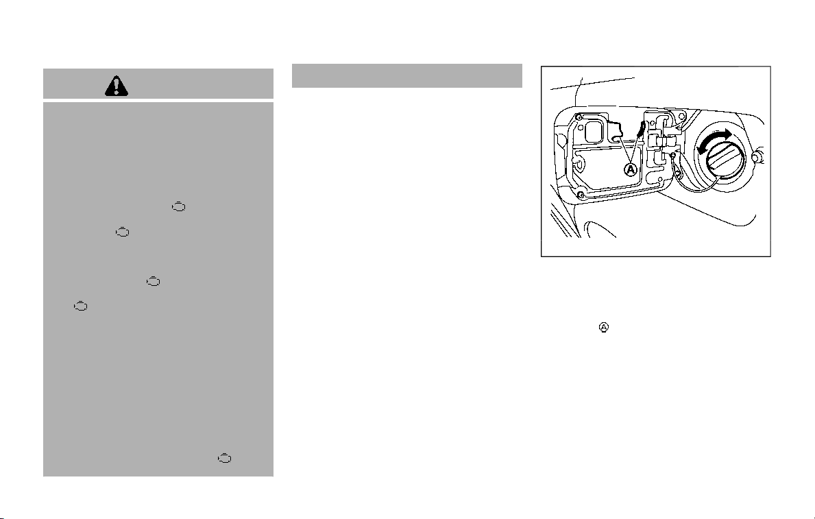
3-28 Pre-driving checks and adjustments
CAUTION
. If fuel is spilled on the vehicle
body, flush it away with water to
avoid paint damage.
. Insert the cap straight into the
fuel-filler tube, then tighten until
the fuel-filler cap clicks. Failure to
tighten the fuel-filler cap properly
may cause the
malfunction
indicator light (MIL) to illuminate.
If the
light illuminates be-
cause the fuel-filler cap is loose
or missing, tighten or install the
cap and continue to drive the
vehicle. The
light should turn
off after a few driving trips. If the
light does not turn off after a
few driving trips, have the vehicle
inspected. It is recommended you
visit a NISSAN dealer for this
service.
. The LOOSE FUEL CAP warning will
appear if the fuel-filler cap is not
properly tightened. It may take a
few driving trips for the message
to be displayed. Failure to tighten
the fuel-filler cap properly after
the LOOSE FUEL CAP warning
appears may cause the
Mal-
function Indicator Light (MIL) to
illuminate.
Turn the cap counterclockwise to re-
move. To tighten, turn the cap clockwise
until a single click is heard.
SPA2753
To remove the fuel-filler cap:
1. Turn the fuel-filler cap counterclock-
wise to remove.
2. Put the fuel-filler cap on the cap
holder
while refueling.
To install the fuel-filler cap:
1. Insert the fuel-filler cap straight into
the fuel-filler tube.
2. Turn the fuel-filler cap clockwise until
a single click is heard.
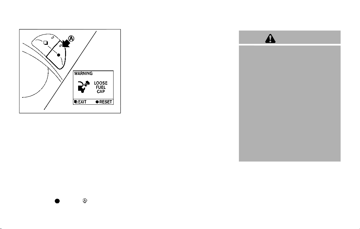
SPA2815
LOOSE FUEL CAP warning
The LOOSE FUEL CAP warning appears on
the vehicle information display when the
fuel-filler cap is not tightened correctly
after the vehicle has been refueled. It may
take a few driving trips for the warning to
be displayed.
To turn off the warning, perform the
following:
1. Remove and install the fuel-filler cap
as soon as possible. (See “Fuel-filler
cap” (P.3-27).)
2. Tighten the fuel-filler cap until it clicks.
3. Push the
switch on the right
side of the combination meter panel
for longer than 1 second to turn off the
LOOSE FUEL CAP warning after tigh-
tening the fuel cap.
WARNING
. Do not adjust the steering wheel
while driving. You could lose con-
trol of your vehicle and cause an
accident.
. Do not adjust the steering wheel
any closer to you than is neces-
sary for proper steering opera-
tion and comfort. The driver’s air
bag inflates with great force. If
you are unrestrained, leaning for-
ward, sitting sideways or out of
position in any way, you are at
greater risk of injury or death in a
crash. You may also receive ser-
ious or fatal injuries from the air
bag if you are up against it when
it inflates. Always sit back against
the seatback and as far away as
practical from the steering wheel.
Always use the seat belts.
Pre-driving checks and adjustments 3-29
TILT/TELESCOPIC STEERING
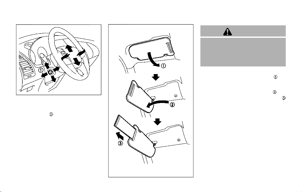
3-30 Pre-driving checks and adjustments
SPA2754
ELECTRIC OPERATION
Tilt or telescopic operation
Move the lever to adjust the steering
wheel up or down, forward or rearward to
the desired position.
Entry/Exit function operation (if so
equipped):
The automatic drive positioner system
will make the steering wheel move up
automatically when the driver’s door is
opened with the ignition switch in the
LOCK position. This lets the driver get into
and out of the seat more easily.
For more information, see “Automatic
drive positioner” (P.3-40).
SIC3451
CAUTION
. Do not store the main sun visor
before storing the extension sun
visor.
. Do not pull the extension sun
visor forcedly downward.
1. To block out glare from the front,
swing down the main sun visor
.
2. To block glare from the side, remove
the main sun visor from the center
mount and swing it to the side
.
3. Draw out the extension sun visor
from the main sun visor to block from
further glare.
SUN VISORS
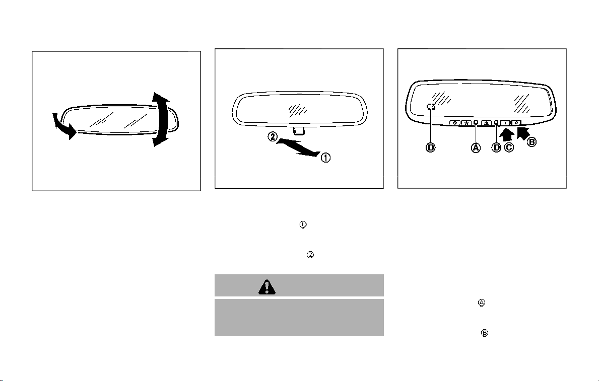
SPA2447
INSIDE MIRROR
Adjust the height and the angle of the
inside mirror to the desired position.
SPA2143
Manual anti-glare type (if so
equipped)
The night position will reduce glare
from the headlights of vehicles behind
you at night.
Use the day position
when driving in
daylight hours.
WARNING
Use the night position only when
necessary, because it reduces rear
view clarity.
SPA2450-A
Automatic anti-glare type (if so
equipped)
The inside mirror is designed so that it
automatically changes reflection accord-
ing to the intensity of the headlights of
the following vehicle.
The anti-glare system will be automati-
cally turned on when the ignition switch is
placed in the ON position.
When the anti-glare system is turned on,
the indicator light
will illuminate and
excessive glare from the headlights of the
vehicle behind you will be reduced.
Push the “*” switch
to make the inside
rearview mirror operate normally. The
Pre-driving checks and adjustments 3-31
MIRRORS

3-32 Pre-driving checks and adjustments
indicator light will turn off. Push the “I”
switch
to turn the system on.
Do not allow any object to cover the
sensors
or apply glass cleaner on
them. Doing so will reduce the sensitiv-
ity of the sensor, resulting in improper
operation.
For the HomeLink® Universal Transceiver
operation, see “HomeLink® Universal
Transceiver (Type A)” (P.2-70).
Intelligent Rear View Mirror (if so
equipped)
WARNING
Failure to follow the warnings and
instructions for proper use of the
Intelligent Rear View Mirror could
result in serious injury or death.
. The Intelligent Rear View Mirror is
a convenience feature but it is not
a substitute for proper vehicle
operation. The system has areas
where objects cannot be viewed.
Check the blind spot of the In-
telligent Rear View Mirror before
vehicle operation. The driver is
always responsible for safe driv-
ing.
. Do not disassemble or modify the
Intelligent Rear View Mirror, the
camera unit or wirings. If you do,
it may result in accidents or fire.
In case you notice smoke or smell
coming from the Intelligent Rear
View Mirror, stop using the sys-
tem immediately. It is recom-
mended that you see a NISSAN
dealer for servicing.
. Do not operate the Intelligent
Rear View Mirror while driving.
Doing so can be a distraction
and it could lose control of your
vehicle and cause an accident or
serious injury.
. Do not gaze into the Intelligent
Rear View Mirror display during
driving. It may cause a distraction
and it could lose control of your
vehicle and cause an accident or
serious injury.
. Do not put a cigarette or flames
to the Intelligent Rear View Mir-
ror, the camera unit or wirings. It
may cause a fire.
. Be sure to adjust the Intelligent
Rear View Mirror before driving.
Switch the system to the conven-
tional rearview mirror mode and
be properly seated on the driver’s
seat. Then adjust the mirror so as
to see the rear window properly.
Driving without adjusting the mir-
ror may cause difficulty in watch-
ing the display at Intelligent Rear
View Mirror mode (camera view
mode) due to the reflection from
the surface of the mirror.
. If the Intelligent Rear View Mirror
malfunctions, immediately switch
the system to the conventional
rearview mirror mode.
. When strong light (for example,
sunlight or high beams from fol-
lowing vehicles) enters the cam-
era, a light beam or a glaring light
may appear on the monitor
screen of the Intelligent Rear
View Mirror. In that case, switch
the system to the conventional
rearview mirror mode appropri-
ately.
. If dirt, rain or snow accumulates
on the exterior glass surface cov-
ering the camera, the Intelligent
Rear View Mirror may not display
objects clearly. Use of the rear
window wiper/washer may im-
prove visibility, but if not, switch
the Intelligent Rear View Mirror to
the conventional rearview mirror
mode until a time the glass cov-
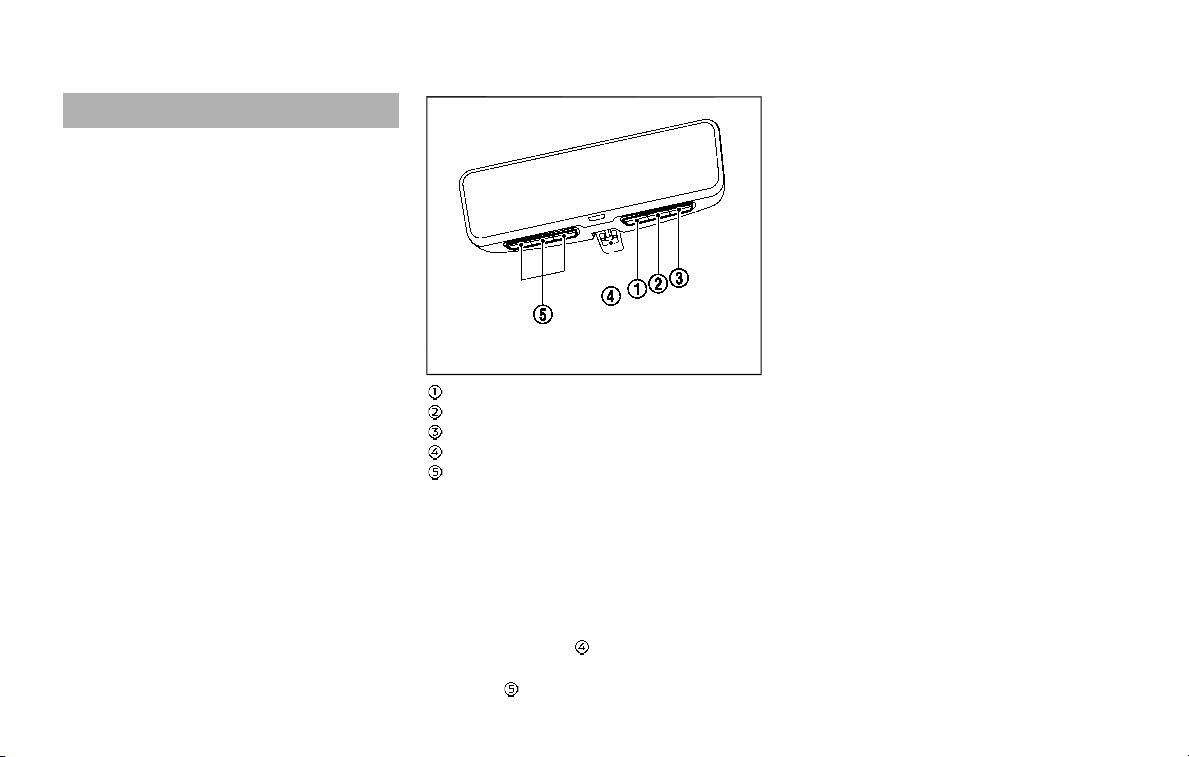
ering the camera can be cleaned.
JVP0515X
MENU button
Left button
Right button
Mode select lever
HomeLink® buttons (1-3)
Components:
Intelligent Rear View Mirror provides a
clear rearview from a camera located on
the rear of the vehicle. Intelligent Rear
View Mirror has two modes: conventional
rearview mirror mode and Intelligent Rear
View Mirror mode (camera view mode).
You can switch these two modes by the
mode select lever
.
For the operation of the HomeLink®
buttons
, see “HomeLink® Universal
Transceiver (Type B)” (P.2-74).
Pre-driving checks and adjustments 3-33
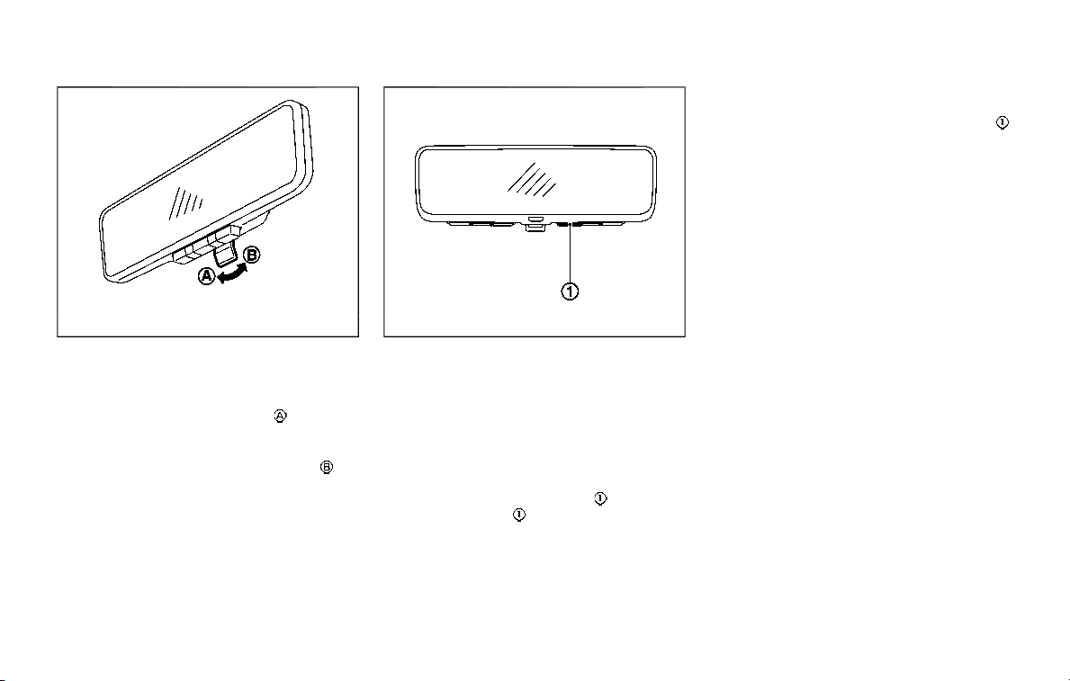
3-34 Pre-driving checks and adjustments
JVP0489X
How to change the mode:
The mode can be switched when the
ignition switch is in the ON position.
. Pull the mode select lever
to switch
to the Intelligent Rear View Mirror
mode (camera view mode).
. Push the mode select lever
to
switch to the conventional rearview
mirror mode.
JVP0506X
How to make settings of Intelligent Rear
View Mirror:
You can choose display settings of the
Intelligent Rear View Mirror such as
brightness, camera angle, textual indica-
tion ON or OFF and language.
When the Intelligent Rear View Mirror
mode is on, setting menu can be selected
by pushing the MENU button
. Each time
the MENU button
is pushed, the setting
menu will change as follows:
MENU (initial screen) ?BRIGHTNESS ?
DOWN/UP ? ROTATION ? INDICATION
? DIMMING MIRROR ? LANGUAGE ?
MENU (initial screen)
NOTE:
. To switch the image quality adjust-
ment items with the MENU button
,
push the button within 5 seconds
after completing the adjustment of
the previous item. If 5 seconds or
more pass, the monitor will return to
MENU (initial screen).
. When one of the HomeLink® buttons
is pushed, the monitor will display
the HomeLink® screen.
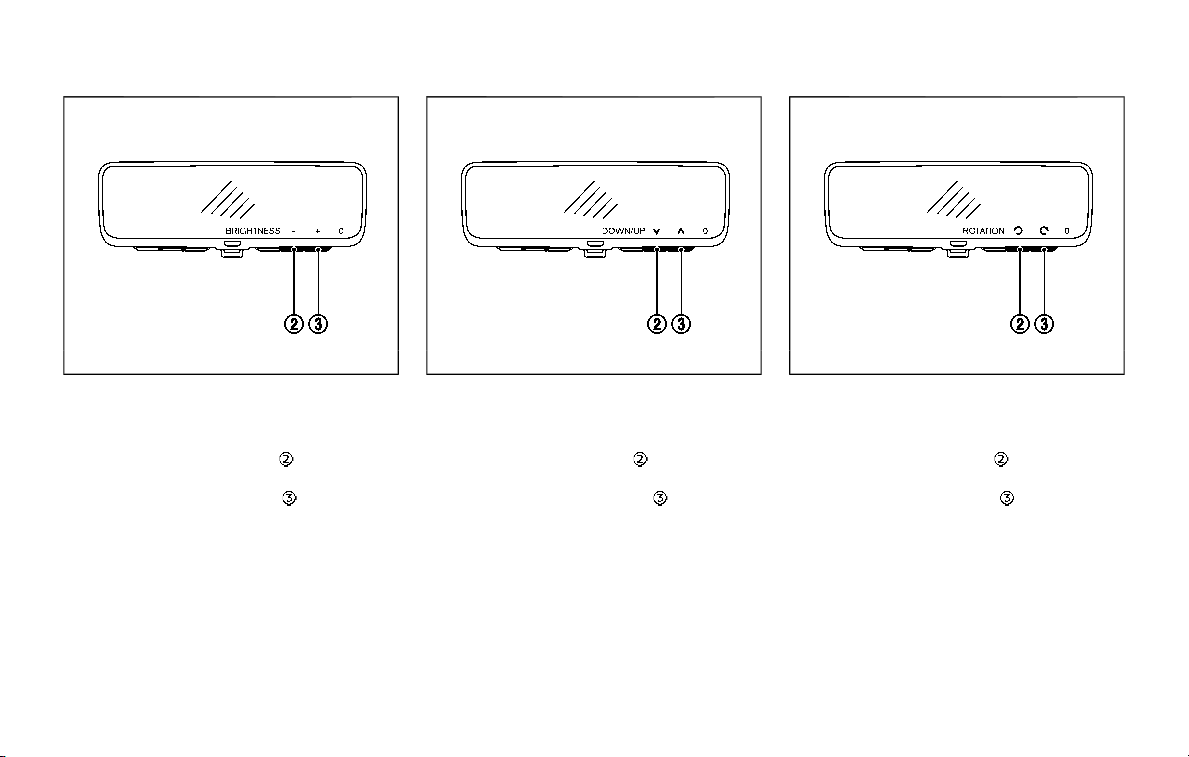
JVP0507X
BRIGHTNESS
The brightness of the display screen can
be adjusted.
. Push the left button
to dim the
screen.
. Push the right button
to brighten
the screen.
JVP0508X
DOWN/UP
The vertical camera angle of the display
screen can be adjusted.
. Push the left button
to down the
camera angle.
. Push the right button
to up the
camera angle.
JVP0510X
ROTATION
The camera angle of the display screen
can be rotated.
. Push the left button
to rotate the
camera angle to the left.
. Push the right button
to rotate the
camera angle to the right.
Pre-driving checks and adjustments 3-35

3-36 Pre-driving checks and adjustments
JVP0511X
INDICATION
The textual indication can be turned on or
off on the Intelligent Rear View Mirror
display screen.
. Push the right button
to disable the
textual indication on the display
screen.
. Push the left button
to enable the
textual indication on the display
screen.
JVP0514X
DIMMING MIRROR
The mirror is designed so that it auto-
matically changes reflection according to
the intensity of the headlights of the
following vehicle. You can enable or
disable the automatic anti-glare mode.
. Push the left button
to enable the
automatic anti-glare mode.
. Push the right button
to disable the
automatic anti-glare mode.
JVP0512X
LANGUAGE
The language of the textual indication
can be selected on the Intelligent Rear
View Mirror display screen.
Select the language by using the
or
button. You can select either English or
French. The language setting will be
retained even if the engine is restarted.
Intelligent Rear View Mirror system
precautions:
NOTE:
. Long-term use of this system in
stopping engine may cause battery
to be discharged.

. Do not attach an antenna of wireless
device near the Intelligent Rear View
Mirror. Electric wave from wireless
device may cause disturbed image
in Intelligent Rear View Mirror.
. Do not push buttons excessively or
operating the lever roughly may
cause a system failure or the Intelli-
gent Rear View Mirror itself to drop.
. Never turn the body of Intelligent
Rear View Mirror by 90° or more. It
may damage the Intelligent Rear
View Mirror.
. Do not apply strong shocks to the
body of Intelligent Rear View Mirror.
It may cause a system failure.
. Do not apply heavy load to the
camera and camera-cover on the
rear of the vehicle. It may cause the
camera to be removed or may cause
a system failure.
. If it is difficult to see the Intelligent
Rear View Mirror display screen be-
cause of a strong external light,
switch the mode to the conventional
rearview mirror mode for better use.
. Close the sunshade (if so equipped)
when the Intelligent Rear View Mir-
ror display screen is unclear due to
strong external light.
JVP0559X
Flicker image (example)
. When LED headlights are viewed on
the Intelligent Rear View Mirror dis-
play, the images may flicker. This is
normal.
. Due to diffused reflection from ex-
ternal environment, images on the
screen may flicker. This is not a
malfunction.
. A quick movement of a thing may
not be able to display on the camera
view screen. This is not a malfunc-
tion.
. Turn on the headlights at twilight or
in a tunnel, etc.
. The Intelligent Rear View Mirror
mode (camera view mode) display
is different from the conventional
rearview mirror. Objects in the dis-
play may differ from actual distance.
Do not solely rely on the Intelligent
Rear View Mirror. Always rely on
your own operation to avoid acci-
dents.
. If the brightness of the camera view
display is adjusted to excessive
bright level, it may cause an eye-
strain in the driving. Adjust the
brightness properly.
. Use the rear window wiper when it
rains. If the camera view image is
still unclear when the rear window
wiper is in operation, check the
deterioration of the rear window
wiper blade.
. When using the rear window wiper,
images on the screen may flicker.
This is not a malfunction.
. Defog the rear window with defros-
ter when rear window is fogged. Use
the conventional rearview mirror
mode until the rear window is fully
defogged.
. The display of the Intelligent Rear
View Mirror may become hot. This is
not a malfunction.
Pre-driving checks and adjustments 3-37
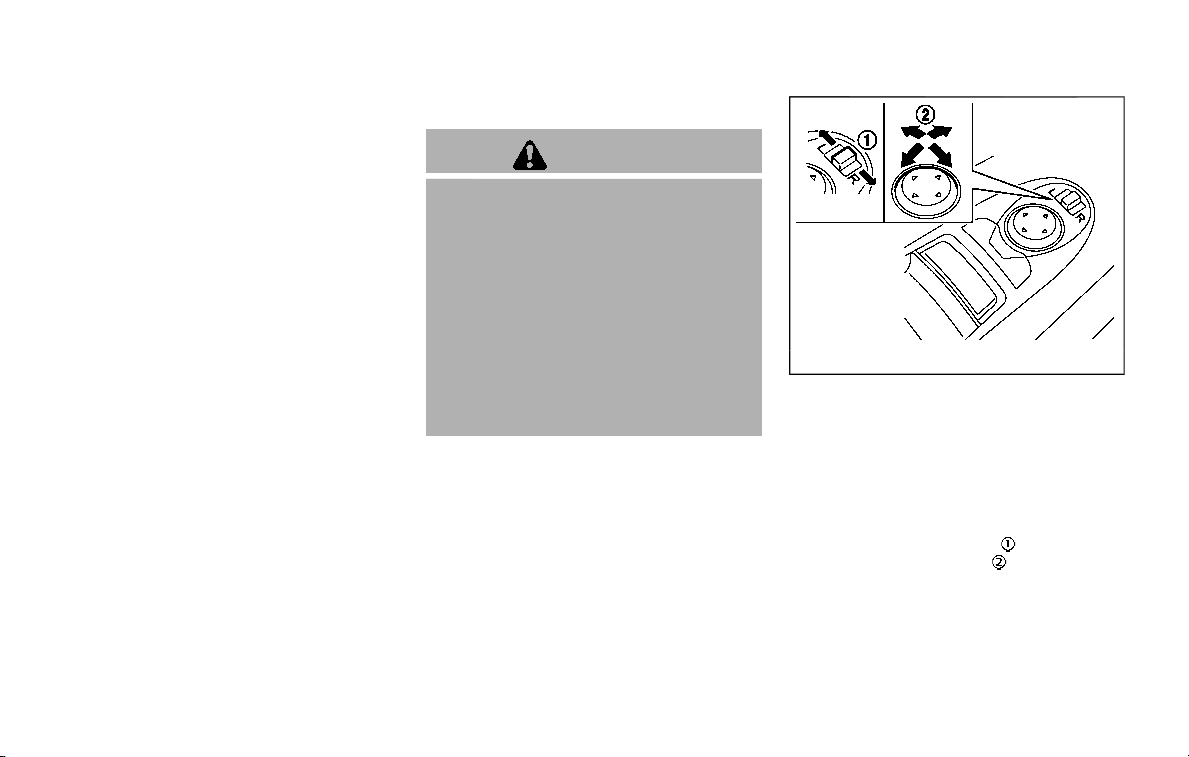
3-38 Pre-driving checks and adjustments
. The color of an object in the distance
or in the dark may be difficult to be
recognized. This is not a malfunc-
tion.
System maintenance (Intelligent Rear
View Mirror):
. Always keep the mirror and camera
area of the rear window clean.
. Clean the mirror and the camera lens
with a dry soft cloth.
. When clean the camera area of the
rear window, using a soft cloth dam-
pend with water and a few neutral
detergent. And after, the dry it up with
dry soft cloth.
. If the image on the Intelligent Rear
View Mirror display screen is still un-
clear even after cleaning the camera
area of the rear window, an oil film
may be adhering to the rear window
glass. Clean the rear window glass
with an oil film remover.
. Never use alcohol, benzine, thinner, or
any similar material to clean the
mirror or camera lens. It will cause a
discoloration, deterioration or a sys-
tem malfunction.
. Do not attach a sticker (including
transparent material) on the camera
area of the rear window.
OUTSIDE MIRRORS
WARNING
. Objects viewed in the outside
mirror on the passenger side are
closer than they appear. Be care-
ful when moving to the right.
Using only this mirror could cause
an accident. Use the inside mirror
or glance over your shoulder to
properly judge distances to other
objects.
. Do not adjust the mirrors while
driving. You could lose control of
your vehicle and cause an acci-
dent.
SPA2739
Adjusting outside mirrors
The outside mirror control switch is
located on the driver’s door armrest.
The outside mirror will operate only when
the ignition switch is in the ACC or ON
position.
Move the switch right or left to select the
right or left side mirror
, then adjust
using the control switch
.
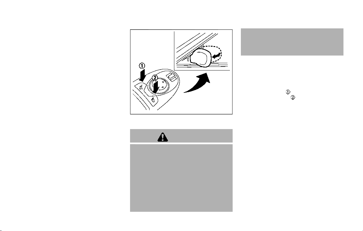
Defrosting outside mirrors
The outside mirrors will be heated when
the rear window defroster switch is
operated. (See “Rear window and outside
mirror defroster switch” (P.2-36).)
SPA2738
Power foldable outside mirrors
CAUTION
. Do not touch the mirrors while
they are moving. Your hand may
be pinched, and the mirror may
malfunction.
. Do not drive with the mirrors
stored. You will be unable to see
behind the vehicle.
. If the mirrors were folded or
unfolded by hand, there is a
chance that the mirror will move
forward or backward during driv-
ing. If the mirrors were folded or
unfolded by hand, be sure to
adjust them again electrically be-
fore driving.
The outside mirror remote control oper-
ates when the ignition switch is in the
ACC or ON position.
To fold the outside mirrors, push the
outside mirror folding switch to the
“CLOSE” position
. To unfold, push to
the “OPEN” position
.
If mirrors are manually operated or
bumped, the mirror body can become
loose at the pivot point. To correct
electronic mirror operation, cycle the
mirrors by pushing “CLOSE” until comple-
tely closed, then push “OPEN” until the
mirrors are in the open position.
Reverse tilt-down feature (if so
equipped)
When backing up the vehicle, the right
and left outside mirrors will turn down-
ward automatically to provide better rear
visibility.
1. Place the ignition switch in the ON
position.
2. Move the shift lever to the R (Reverse)
position.
Pre-driving checks and adjustments 3-39
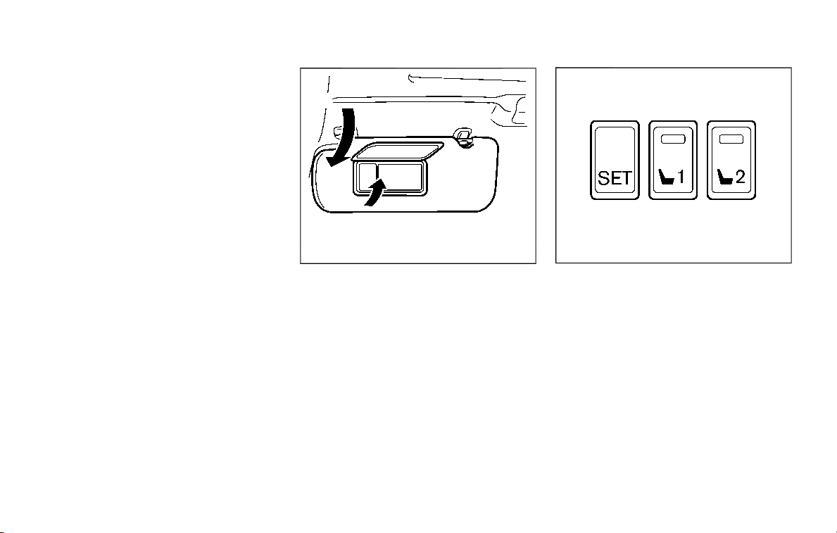
3-40 Pre-driving checks and adjustments
3. Choose the right or left outside mirror
by operating the outside mirror con-
trol switch.
4. The outside mirror surfaces move
downward.
When one of the following conditions has
occurred, the outside mirror surfaces will
return to their original positions.
. The shift lever is moved to any posi-
tion other than R (Reverse).
. The outside mirror control switch is
set to the center position.
. The ignition switch is placed in the
OFF position.
Automatic anti-glare (if so
equipped)
The outside rearview mirrors are de-
signed so that its automatically change
reflection according to the intensity of
the headlights of the vehicle following
you.
The anti-glare system will be automati-
cally turned on when the ignition switch is
placed in the ON position.
SIC4448
VANITY MIRROR
To use the front vanity mirror, pull down
the sun visor and pull up the cover.
JVP0247X
SET/memory switches
The automatic drive positioner system
has three features:
. Entry/exit function
. Memory storage
. Setting memory function
ENTRY/EXIT FUNCTION
This system is designed so that the
driver’s seat and steering column will
automatically move when the automatic
transmission shift lever is in the P (Park)
position. This allows the driver to get into
and out of the driver’s seat more easily.
The driver’s seat will slide backward and
the steering wheel will move up when the
driver’s door is opened with the ignition
AUTOMATIC DRIVE POSITIONER (if
so equipped)

switch in the LOCK position.
The driver’s seat and steering wheel will
return to the previous positions when the
ignition switch is pushed to the ACC
position.
The driver’s seat will not return to the
previous positions if the seat or steering
adjusting switch is operated when the
seat is at the exit position.
Cancel or activate entry/exit func-
tion
The shift lever must be in the P (Park)
position with the ignition switch in the
OFF position.
The entry/exit function can be activated
or canceled by pressing and holding the
SET switch for more than 10 seconds.
The entry/exit function can also be acti-
vated or canceled if the “Lift Steering
Wheel on Exit” key or “Slide Driver Seat
Back on Exit” key is turned to ON or OFF in
the Vehicle settings on the center display.
(See NissanConnect® Owner’s Manual.)
Initialize entry/exit function
If the battery cable is disconnected, or if
the fuse opens, the entry/exit function
will not work though this function was set
on before. In such a case, after connect-
ing the battery or replacing with a new
fuse, open and close the driver’s door
more than two times after the ignition
switch is turned from the ON position to
the LOCK position. The entry/exit func-
tion will be activated.
MEMORY STORAGE
Two positions for the driver’s seat, steer-
ing column and outside mirrors can be
stored in the automatic drive positioner
memory. Follow these procedures to use
the memory system.
1. Move the shift lever to the P (Park)
position.
2. Adjust the driver’s seat, steering col-
umn and outside mirrors to the de-
sired positions by manually operating
each adjusting switch. For additional
information, see “Seats” (P.1-3) and
“Tilt/telescopic steering” (P.3-29) and
“Outside mirrors” (P.3-38).
3. Push the SET switch and, within 5
seconds, push the memory switch (1
or 2) fully for at least 1 second.
The indicator light for the pushed
memory switch will stay on for ap-
proximately 5 seconds after pushing
the switch.
When the memory is stored in the
memory switch (1 or 2), a buzzer will
sound.
If memory is stored in the same
memory switch, the previous memory
will be deleted.
Linking Intelligent Key to a stored
memory position
The Intelligent Key can be linked to a
stored memory position with the follow-
ing procedure.
1. Follow the steps for storing a memory
position.
2. While the indicator light for the mem-
ory switch being set is illuminated for
5 seconds, push the
button on the
Intelligent Key. If the indicator light
blinks, the Intelligent Key is linked to
that memory setting.
Push the ignition switch to the OFF
position, and then push the
button
on the Intelligent Key. The driver’s seat,
steering wheel and outside mirrors will
move to the memorized position.
Pre-driving checks and adjustments 3-41

3-42 Pre-driving checks and adjustments
Confirming memory storage
. Push the ignition switch to the ON
position and push the SET switch. If
the main memory has not been
stored, the indicator light will come
on for approximately 0.5 second.
When the memory has stored in posi-
tion, the indicator light will stay on for
approximately 5 seconds.
. If the battery cable is disconnected, or
if the fuse opens, the memory will be
canceled. In this case, reset the de-
sired position using the previous pro-
cedure.
. If optional Intelligent Keys are added
to your vehicle, the memory storage
procedure to switch 1 or 2 and linking
Intelligent Key procedure to a stored
memory position should be per-
formed again for each Intelligent Key.
For additional Intelligent Key informa-
tion, see “Keys” (P.3-2).
Selecting the memorized position
1. Move the shift lever to the P (Park)
position.
2. Use one of the following methods to
move the driver’s seat, the outside
mirrors and the steering wheel.
.
Push the memory switch (1 or 2)
fully for at least 1 second.
The driver’s seat, steering column and
outside mirrors will move to the
memorized position or to the exit
position when the entry/exit function
is set to active with the indicator light
flashing, and then the light will stay on
for approximately 5 seconds.
SETTING MEMORY FUNCTION
The status of the following settings can
be linked to the Intelligent Key and the
memorized settings can be available for
each Intelligent Key.
. Air conditioner system
. Navigation system (if so equipped)
. Audio system
To use the memory function, lock the
doors with the Intelligent Key that is
linked to the settings.
To enable the memorized settings:
1. Carry the Intelligent Key that is linked
to the settings, and unlock the doors
by pushing the driver’s door handle
request switch or “UNLOCK”
but-
ton on the Intelligent Key.
2. Place the ignition switch in the ON
position. “Connection with the key has
been done” will be displayed on the
screen and the memorized settings
are available (only when a new Intel-
ligent Key is used).
SYSTEM OPERATION
The automatic drive positioner system
will not work or will stop operating under
the following conditions:
. When the vehicle speed is above 0
MPH (0 km/h) or 4 MPH (7 km/h) for
some limited functions such linking an
Intelligent Key to the vehicle when the
power source is turned on from off or
during the Exit function.
. When any of the memory switches are
pushed while the automatic drive
positioner is operating.
. When the adjusting switch for the
driver’s seat and steering column is
turned on while the automatic drive
positioner is operating.
. When the seat has already been
moved to the memorized position.
. When no seat position is stored in the
memory switch.
. When the shift lever is moved from the
P (Park) position to any other position.

4 Monitor, heater, air conditioner, audio,
phone and voice recognition systems
NissanConnect® Owner’s Manual .................................... 4-2
Safety note ........................................................................................ 4-2
RearView Monitor (if so equipped) ................................. 4-3
RearView Monitor system operation ..................... 4-4
How to read the displayed lines ................................ 4-4
Difference between predictive and
actual distances ...................................................................... 4-5
How to park with predictive course lines .......... 4-6
Sonar indicator ........................................................................ 4-7
Adjusting the screen ........................................................... 4-8
Predictive course line settings .................................... 4-8
RearView Monitor system limitations .................... 4-8
System maintenance .......................................................... 4-9
Intelligent Around View Monitor (if
so equipped) .................................................................................. 4-10
Intelligent Around View Monitor
system operation ................................................................ 4-12
How to adjust the screen view ................................ 4-19
Intelligent Around View Monitor settings ....... 4-20
Intelligent Around View Monitor
system limitations .............................................................. 4-22
System maintenance ....................................................... 4-24
Camera aiding sonar function (models with
Intelligent Around View Monitor) .................................. 4-25
Sonar system operation ................................................ 4-25
Turning on and off the sonar function .......... 4-26
Sonar system limitations ........................................... 4-27
System temporarily unavailable ........................... 4-28
System maintenance .................................................... 4-28
Moving Object Detection (MOD) ................................... 4-29
MOD system operation ................................................ 4-30
Turning on and off the MOD system ............... 4-31
MOD system limitations .............................................. 4-32
System maintenance .................................................... 4-33
Ventilators ...................................................................................... 4-34
Center ventilators ............................................................ 4-34
Side ventilators .................................................................. 4-34
Rear ventilators .................................................................. 4-34
Heater and air conditioner ................................................ 4-35
Automatic air conditioner ......................................... 4-36
Rear automatic air conditioning system ....... 4-39
Operating tips ..................................................................... 4-43
Linking Intelligent Key (if so equipped)........... 4-43
In-cabin microfilter .......................................................... 4-43
Servicing air conditioner ............................................. 4-43
Antenna ............................................................................................ 4-43
Window antenna ............................................................... 4-43
Satellite antenna ............................................................... 4-44
Car phone or CB radio ......................................................... 4-44

4-2 Monitor, heater, air conditioner, audio, phone and voice recognition systems
For models with NissanConnect® with
Navigation (if so equipped) and Services
(if so equipped), refer to the NissanCon-
nect® Owner’s Manual regarding the fol-
lowing information.
. Audio system
. Bluetooth® Hands-Free Phone
. NissanConnect® Services
. SiriusXM Traffic
TM
. SiriusXM® Travel Link
. SiriusXM® Radio
. Navigation system
. Voice Recognition System
. Information and settings viewable on
NissanConnect®
WARNING
. Do not disassemble or modify
this system. If you do, it may
result in accidents, fire, or electric
shock.
. Do not use this system if you
notice any abnormality, such as
a frozen screen or lack of sound.
Continued use of the system may
result in accident, fire or electric
shock.
. In case you notice any foreign
object in the system hardware,
spill liquid on it, or notice smoke
or smell coming from it, stop
using the system immediately. It
is recommended you visit a
NISSAN dealer for servicing.
Ignoring such conditions may
lead to accidents, fire, or electric
shock.
. Park the vehicle in a safe location
and apply the parking brake to
view the images on the front
center display screen.
CAUTION
Do not use the system when the
engine is not running for extended
periods of time to prevent battery
discharge.
Do not attempt to operate the system in
extreme temperature conditions [below
−4°F (−20°C) and above 158°F (70°C)].
Operating this system under these con-
ditions may result in system malfunc-
tions.
NISSANCONNECT® OWNER’S MANUAL
SAFETY NOTE
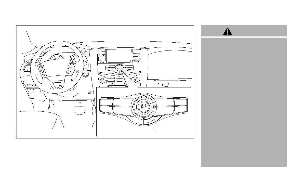
JVH1688X
1. SETTING button
WARNING
Failure to follow the warnings and
instructions for proper use of the
RearView Monitor system could re-
sult in serious injury or death.
. The RearView Monitor is a conve-
nience but it is not a substitute
for proper backing. Always turn
and look out the windows, and
check mirrors to be sure that it is
safe to move before operating
the vehicle. Always back up
slowly.
. The system is designed as an aid
to the driver in showing large
stationary objects directly behind
the vehicle, to help avoid dama-
ging the vehicle.
. The distance guide line and the
vehicle width line should be used
as a reference only when the
vehicle is on a level paved sur-
face. The distance viewed on the
monitor is for reference only and
may be different than the actual
distance between the vehicle and
displayed objects.
Monitor, heater, air conditioner, audio, phone and voice recognition systems 4-3
REARVIEW MONITOR (if so equipped)
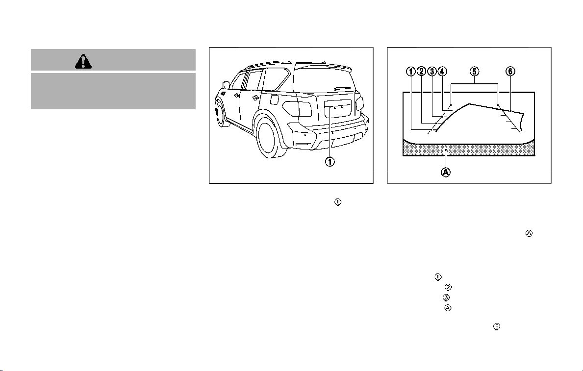
4-4 Monitor, heater, air conditioner, audio, phone and voice recognition systems
CAUTION
Do not scratch the camera lens when
cleaning dirt or snow from the front
of camera.
The RearView Monitor system automati-
cally shows a rear view of the vehicle
when the shift lever is placed in the R
(Reverse) position.
The radio can still be heard while the
RearView Monitor is active.
JVH1395X
To display the rear view, the RearView
Monitor system uses a camera
located
just above the vehicle’s license plate.
REARVIEW MONITOR SYSTEM OP-
ERATION
With the ignition switch in the ON posi-
tion, move the shift lever to the R
(Reverse) position to operate the Rear-
View Monitor.
SAA1896
HOW TO READ THE DISPLAYED
LINES
Guiding lines which indicate the vehicle
width and distances to objects with
reference to the bumper line
are
displayed on the monitor.
Distance guide lines:
Indicate distances from the bumper.
. Red line
: approx. 1.5 ft (0.5 m)
. Yellow line
: approx. 3 ft (1 m)
. Green line
: approx. 7 ft (2 m)
. Green line
(if so equipped): approx.
10 ft (3 m)
Vehicle width guide lines
:
Indicate the approximate vehicle width
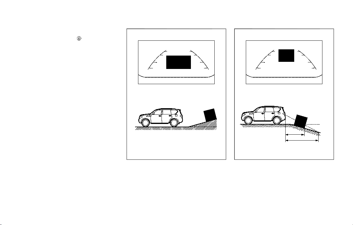
when backing up.
Predictive course lines
:
Indicate the predictive course when back-
ing up. The predictive course lines will be
displayed on the monitor when the shift
lever is in the R (Reverse) position and the
steering wheel is turned. The predictive
course lines will move depending on how
much the steering wheel is turned and
will not be displayed while the steering
wheel is in the neutral position.
The vehicle width guide lines and the
width of the predictive course lines are
wider than the actual width and course.
DIFFERENCE BETWEEN PREDICTIVE
AND ACTUAL DISTANCES
The displayed guidelines and their loca-
tions on the ground are for approximate
reference only. Objects on uphill or down-
hill surfaces or projecting objects will be
actually located at distances different
from those displayed in the monitor
relative to the guidelines (refer to illustra-
tions). When in doubt, turn around and
view the objects as you are backing up, or
park and exit the vehicle to view the
positioning of objects behind the vehicle.
JVH1214X
Backing up on a steep uphill
When backing up the vehicle up a hill, the
distance guide lines and the vehicle width
guide lines are shown closer than the
actual distance. Note that any object on
the hill is farther than it appears on the
monitor.
JVH1215X
Backing up on a steep downhill
When backing up the vehicle down a hill,
the distance guide lines and the vehicle
width guide lines are shown farther than
the actual distance. Note that any object
on the hill is closer than it appears on the
monitor.
Monitor, heater, air conditioner, audio, phone and voice recognition systems 4-5
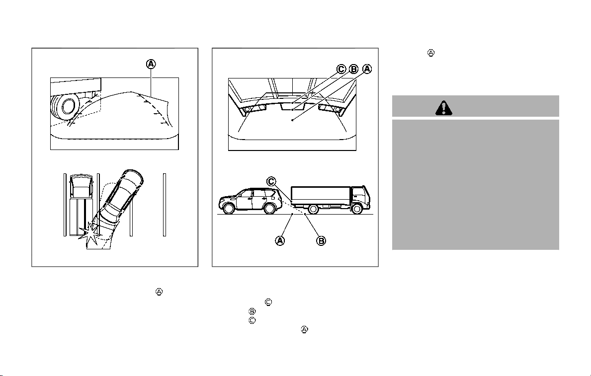
4-6 Monitor, heater, air conditioner, audio, phone and voice recognition systems
SAA1923
Backing up near a projecting object
The predictive course lines do not
touch the object in the display. However,
the vehicle may hit the object if it projects
over the actual backing up course.
JVH1216X
Backing up behind a projecting
object
The position is shown farther than the
position
in the display. However, the
position
is actually at the same dis-
tance as the position
. The vehicle may
hit the object when backing up to the
position
if the object projects over the
actual backing up course.
HOW TO PARK WITH PREDICTIVE
COURSE LINES
WARNING
. If the tires are replaced with
different sized tires, the predic-
tive course line may not be dis-
played correctly.
. On a snow-covered or slippery
road, there may be a difference
between the predictive course
line and the actual course line.
. The displayed lines will appear
slightly off to the right because
the rearview camera is not in-
stalled in the rear center of the
vehicle.
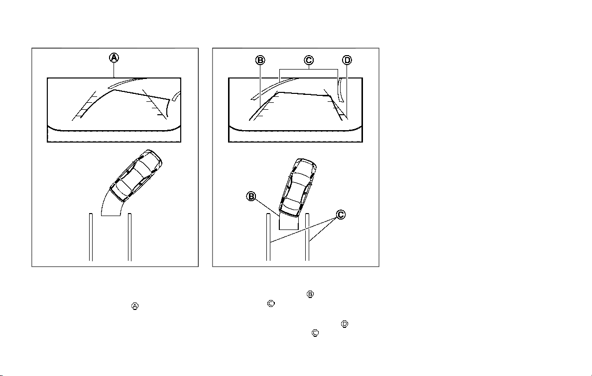
SAA1897
1. Visually check that the parking space
is safe before parking your vehicle.
2. The rearview of the vehicle is dis-
played on the screen
when the shift
lever is moved to the R (Reverse)
position.
SAA1898
3. Slowly back up the vehicle adjusting
the steering wheel so that the pre-
dictive course lines
enter the park-
ing space
.
4. Maneuver the steering wheel to make
the vehicle width guide lines
parallel
to the parking space
while referring
to the predictive course lines.
5. When the vehicle is parked in the
space completely, move the shift lever
to the P (Park) position and apply the
parking brake.
SONAR INDICATOR
When the sonar system is ON, the sonar
indicator will appear in the display. (See
“Sonar system” (P.5-127).)
Monitor, heater, air conditioner, audio, phone and voice recognition systems 4-7
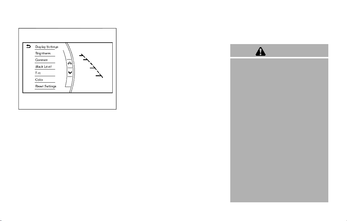
4-8 Monitor, heater, air conditioner, audio, phone and voice recognition systems
JVH1690X
ADJUSTING THE SCREEN
The display settings such as Brightness,
Contrast, Black Level, Tint and Color of
the RearView Monitor can be adjusted.
1. Push the SETTING button while the
RearView Monitor screen is displayed.
2. The Display settings menu is dis-
played. Select an item you wish to
adjust.
3. Adjust the selected item by touching
the “+” or “-” key.
Select “Reset Settings” key to return all
settings to default.
Display settings menu can also be ac-
cessed while the RearView Monitor
screen is not displayed. Push the SETTING
button and select “Camera/Sonar” key,
and then select “Display” key.
NOTE:
Do not adjust any of the display settings
of the RearView Monitor while the
vehicle is moving. Make sure the park-
ing brake is firmly applied.
PREDICTIVE COURSE LINE SET-
TINGS
To toggle on and off the predictive course
lines:
1. Push the SETTING button while the
RearView Monitor screen is not dis-
played.
2. Select “Camera/Sonar” key.
3. Select “Camera” key.
4. Select “Predictive Course Lines” key to
turn the feature on or off. When this
item is turned on, the predictive
course lines will be displayed on the
monitor.
REARVIEW MONITOR SYSTEM LIM-
ITATIONS
WARNING
Listed below are the system limita-
tions for RearView Monitor. Failure to
operate the vehicle in accordance
with these system limitations could
result in serious injury or death.
. The system cannot completely
eliminate blind spots and may
not show every object.
. Underneath the bumper and the
corner areas of the bumper can-
not be viewed on the RearView
Monitor because of its monitoring
range limitation. The system will
not show small objects below the
bumper, and may not show ob-
jects close to the bumper or on
the ground.
. Objects viewed in the RearView
Monitor differ from actual dis-
tance because a wide-angle lens
is used.
. Objects in the RearView Monitor
will appear visually opposite
compared to when viewed in the
rearview and outside mirrors.
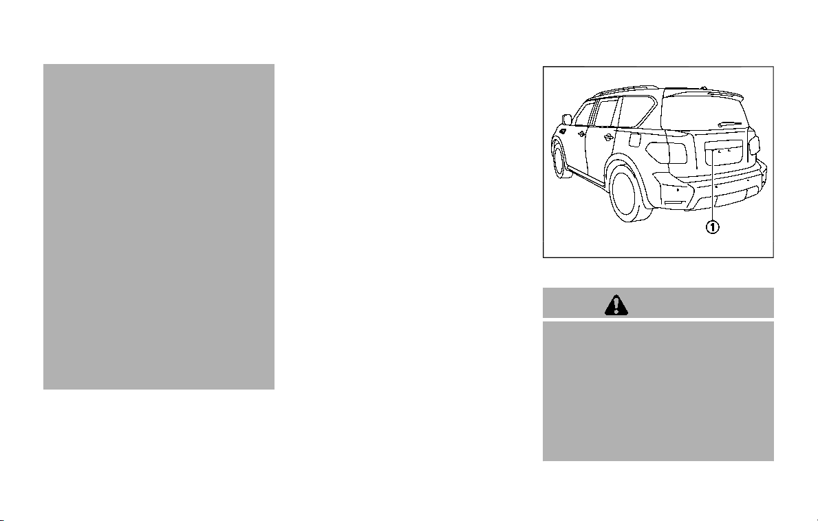
. Use the displayed lines as a re-
ference. The lines are highly af-
fected by the number of
occupants, fuel level, vehicle po-
sition, road conditions and road
grade.
. Make sure that the liftgate is
securely closed when backing up.
. Do not put anything on the rear-
view camera. The rearview cam-
era is installed above the license
plate.
. When washing the vehicle with
high-pressure water, be sure not
to spray it around the camera.
Otherwise, water may enter the
camera unit causing water con-
densation on the lens, a malfunc-
tion, fire or an electric shock.
. Do not strike the camera. It is a
precision instrument. Otherwise,
it may malfunction or cause da-
mage resulting in a fire or an
electric shock.
The following are operating limitations
and do not represent a system malfunc-
tion:
. When the temperature is extremely
high or low, the screen may not clearly
display objects.
. When strong light is directly coming
on the camera, objects may not be
displayed clearly.
. Vertical lines may be seen in objects
on the screen. This is due to strong
reflected light from the bumper.
. The screen may flicker under fluores-
cent light.
. The colors of objects on the RearView
Monitor may differ somewhat from
the actual color of objects.
. Objects on the monitor may not be
clear in a dark environment.
. There may be a delay when switching
to the RearView Monitor.
. When activating the RearView Moni-
tor, the guide lines, the icons and the
messages may not be displayed for a
while.
. If dirt, rain or snow accumulates on
the camera, the RearView Monitor
may not display object clearly. Clean
the camera.
. Do not use wax on the camera win-
dow. Wipe off any wax with a clean
cloth dampened with mild detergent
diluted with water.
JVH1395X
SYSTEM MAINTENANCE
CAUTION
. Do not use alcohol, benzine or
thinner to clean the camera. This
will cause discoloration. To clean
the camera, wipe with a cloth
dampened with diluted mild
cleaning agent and then wipe
with a dry cloth.
. Do not damage the camera as the
monitor screen may be adversely
affected.
Monitor, heater, air conditioner, audio, phone and voice recognition systems 4-9
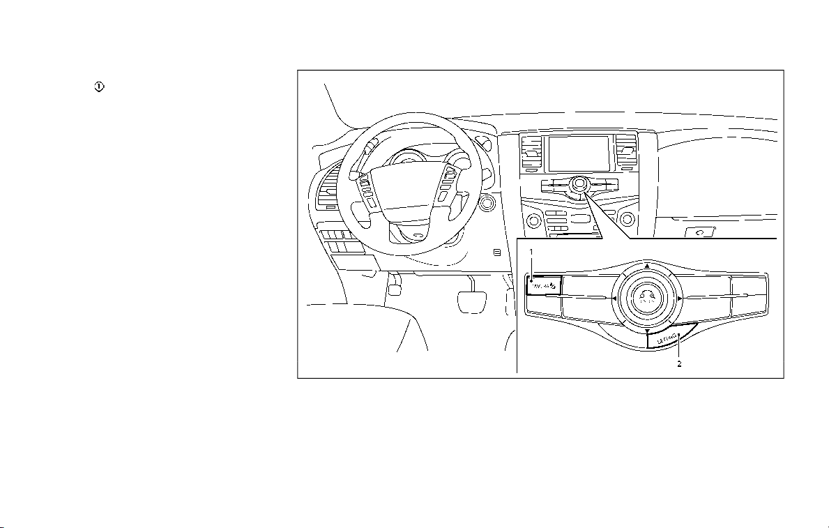
4-10 Monitor, heater, air conditioner, audio, phone and voice recognition systems
If dirt, rain or snow accumulates on the
camera
, RearView Monitor may not
display objects clearly. Clean the camera
by wiping it with a cloth dampened with a
diluted mild cleaning agent and then
wiping it with a dry cloth.
JVH1689X
1. CAMERA button
2. SETTING button
INTELLIGENT AROUND VIEW
MONITOR (if so equipped)
WARNING
Failure to follow the warnings and
instructions for the proper use of the
Intelligent Around View Monitor sys-
tem could result in serious injury or
death.
. The Intelligent Around View Moni-
tor is a convenience feature and
is not a substitute for proper
vehicle operation because it has
areas where objects cannot be
viewed. The four corners of the
vehicle in particular, are areas
where objects do not always ap-
pear in the bird’s-eye, front, or
rear views. Always check your
surroundings to be sure that it is
safe to move before operating
the vehicle. Always operate the
vehicle slowly.
. The driver is always responsible
for safety during parking and
other maneuvers.
CAUTION
Do not scratch the lens when clean-
ing dirt or snow from the front of the
camera.
The Intelligent Around View Monitor sys-
tem is designed as an aid to the driver in
situations such as slot parking or parallel
parking.
The monitor displays various views of the
position of the vehicle in a split screen
format. All views are not available at all
times.
Available views:
. Front view
An approximately 150-degree view of
the front of the vehicle.
. Rear view
An approximately 150-degree view of
the rear of the vehicle.
. Bird’s-eye view
The surrounding view of the vehicle
from above.
. Front-side view
The view around and ahead of the
front passenger’s side wheel.
. Front-wide view
An approximately 180-degree view of
the front of the vehicle.
. Rear-wide view
An approximately 180-degree view of
the rear of the vehicle.
Monitor, heater, air conditioner, audio, phone and voice recognition systems 4-11
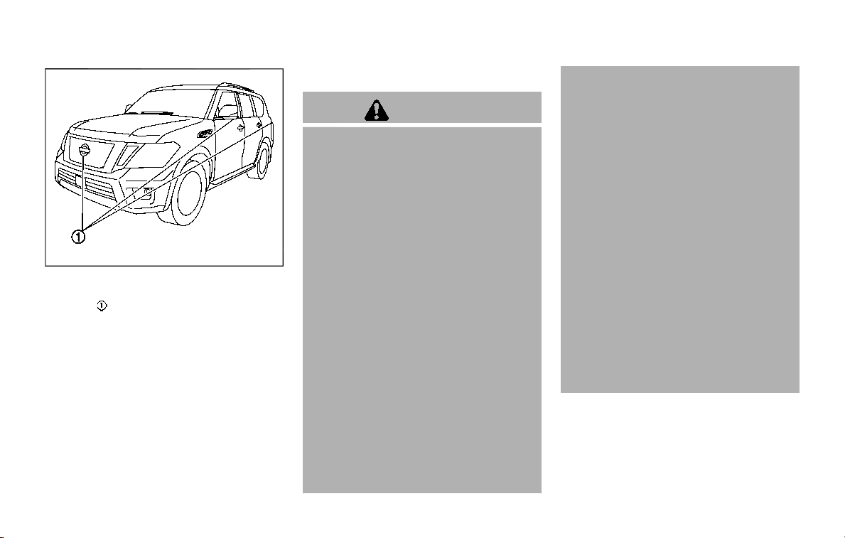
4-12 Monitor, heater, air conditioner, audio, phone and voice recognition systems
JVH1397X
To display the multiple views, the Intelli-
gent Around View Monitor system uses
cameras
located in the front grill, on the
vehicle’s outside mirrors and one just
above the vehicle’s license plate.
INTELLIGENT AROUND VIEW MONI-
TOR SYSTEM OPERATION
With the ignition switch in the ON posi-
tion, move the shift lever to the R
(Reverse) position or press the CAMERA
button to operate the Intelligent Around
View Monitor.
Available views
WARNING
. The distance guide lines and the
vehicle width lines should be
used as a reference only when
the vehicle is on a paved, level
surface. The apparent distance
viewed on the monitor may be
different than the actual distance
between the vehicle and dis-
played objects.
. Use the displayed lines and the
bird’s-eye view as a reference.
The lines and the bird’s-eye view
are greatly affected by the num-
ber of occupants, fuel level, vehi-
cle position, road condition and
road grade.
. If the tires are replaced with
different sized tires, the predic-
tive course lines and the bird’s-
eye view may be displayed incor-
rectly.
. When driving the vehicle up a hill,
objects viewed in the monitor are
further than they appear. When
driving the vehicle down a hill,
objects viewed in the monitor are
closer than they appear.
. Objects in the monitor will appear
visually opposite compared to
when viewed in the rearview and
outside mirrors.
. Use the mirrors or actually look to
properly judge distances to other
objects.
. The distance between objects
viewed in the rear view differs
from actual distance because a
wide-angle lens is used.
. On a snow-covered or slippery
road, there may be a difference
between the predictive course
line and the actual course line.
. The vehicle width and predictive
course lines are wider than the
actual width and course.
. The displayed lines on the rear
view will appear slightly off to the
right because the rearview cam-
era is not installed in the rear
center of the vehicle.

SAA1840
Front view
SAA1896
Rear view
Front and rear view:
Guiding lines that indicate the approx-
imate vehicle width and distances to
objects with reference to the vehicle body
line
are displayed on the monitor.
Distance guide lines
Indicate distances from the vehicle body.
. Red line
: approx. 1.5 ft (0.5 m)
. Yellow line
: approx. 3 ft (1 m)
. Green line
: approx. 7 ft (2 m)
. Green line
(if so equipped): approx.
10 ft (3 m)
Vehicle width guide lines
Indicate the approximate vehicle width.
Predictive course lines
Indicate the predictive course when op-
erating the vehicle. The predictive course
lines will be displayed on the monitor
when the steering wheel is turned. The
predictive course lines will move depend-
ing on how much the steering wheel is
turned and will not be displayed while the
steering wheel is in the straight-ahead
position.
The front view will not be displayed when
the vehicle speed is above 6 MPH (10
km/h).
NOTE:
When the monitor displays the front
view and the steering wheel turns
about 90 degrees or less from the
straight ahead position, both the right
and left predictive course lines
are
displayed. When the steering wheel
turns about 90 degrees or more, a line
is displayed only on the opposite side of
the turn.
Monitor, heater, air conditioner, audio, phone and voice recognition systems 4-13
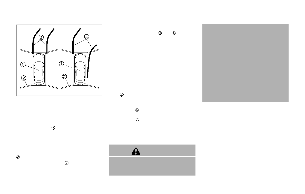
4-14 Monitor, heater, air conditioner, audio, phone and voice recognition systems
WAE0224X
Bird’s-eye view:
The bird’s-eye view shows the overhead
view of the vehicle, which helps confirm
the vehicle position and the predictive
course to a parking space.
The vehicle icon
shows the position of
the vehicle. Note that the size of the
vehicle icon on the bird’s-eye view may
differ somewhat from the actual distance
to the vehicle.
The areas that the cameras cannot cover
are indicated in black.
The non-viewable area
is highlighted in
yellow for several seconds after the bird’s-
eye view is displayed. It will be shown only
the first time after the ignition switch is
placed in the ON position.
Predictive course lines (
and ) indicate
the predictive course when operating the
vehicle. The predictive course lines will be
displayed on the monitor when the steer-
ing wheel is turned. The predictive course
lines will move depending on how much
the steering wheel is turned and will not
be displayed while the steering wheel is in
the straight-ahead position.
When the monitor displays the front view
and the steering wheel turns about 90
degrees or less from the straight-ahead
position, the two green predictive course
lines
are shown in front of the vehicle.
When the steering wheel turns about 90
degrees or more, one green predictive
course line
is shown in front of the
vehicle and the other green predictive
course line
is shown at side of the
vehicle.
When the monitor displays the rear view,
the predictive course lines are shown at
back of the vehicle.
WARNING
. Objects in the bird’s-eye view will
appear further than the actual
distance.
. Tall objects, such as a curb or
vehicle, may be misaligned or not
displayed at the seam of the
views.
. Objects that are above the cam-
era cannot be displayed.
. The view for the bird’s-eye view
may be misaligned when the
camera position alters.
. A line on the ground may be
misaligned and is not seen as
being straight at the seam of the
views. The misalignment will in-
crease as the line proceeds away
from the vehicle.
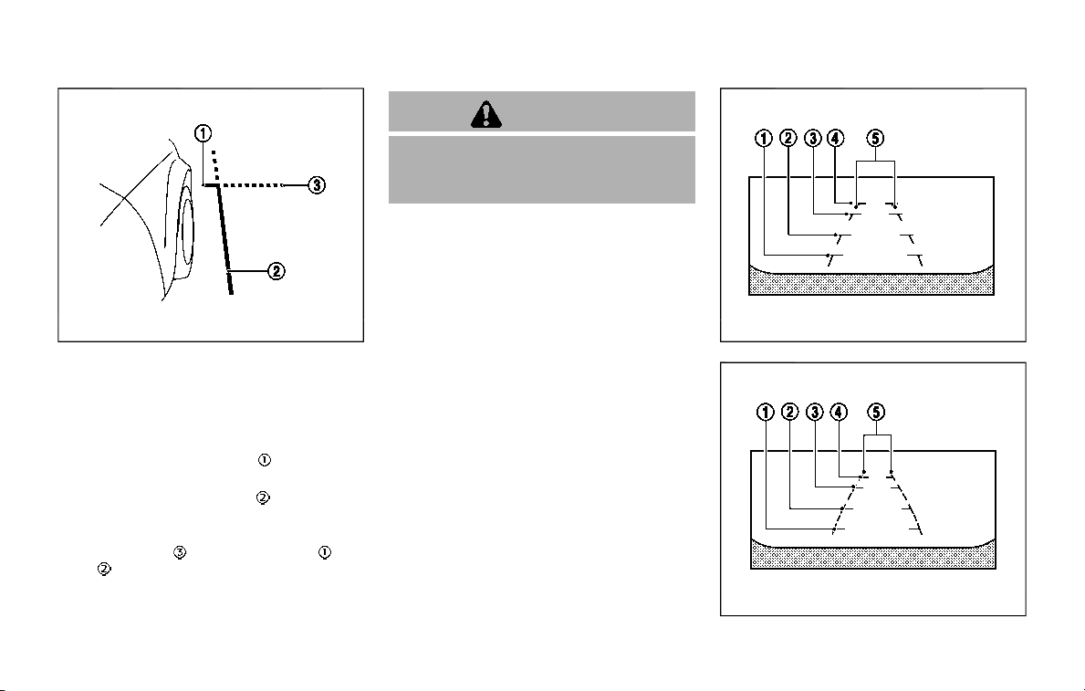
JVH1141X
Front-side view:
Guiding lines:
Guiding lines that indicate the width and
the front end of the vehicle are displayed
on the monitor.
The front-of-vehicle line
shows the
front part of the vehicle.
The side-of-vehicle line
shows the
vehicle width including the outside mir-
rors.
The extensions
of both the front and
side
lines are shown with a green
dotted line.
CAUTION
The turn signal light may look like
the side-of-vehicle line. This is not a
malfunction.
JVH1142X
Front-wide view
JVH1143X
Rear-wide view
Monitor, heater, air conditioner, audio, phone and voice recognition systems 4-15
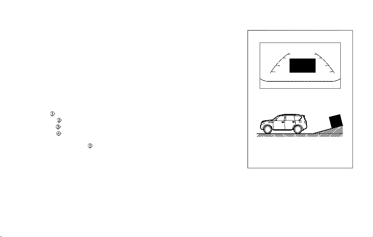
4-16 Monitor, heater, air conditioner, audio, phone and voice recognition systems
Front-wide/rear-wide view:
The front-wide/rear-wide view shows a
wider area on the entire screen and
allows the checking of the blind corners
on the right and left sides. The front-
wide/rear-wide view displays an approxi-
mately 180-degree area while the front
view and the rear view display an ap-
proximately 150-degree area. The predic-
tive course lines are not displayed when
using the front-wide/rear-wide view.
Distance guide lines
Indicates distances from the vehicle body.
. Red line
: approx. 1.5 ft (0.5 m)
. Yellow line
: approx. 3 ft (1 m)
. Green line
: approx. 7 ft (2 m)
. Green line
(if so equipped): approx.
10 ft (3 m)
Vehicle width guide lines
Indicates the approximate vehicle width.
Difference between predicted and
actual distances
The displayed guidelines and their loca-
tions on the ground are for approximate
reference only. Objects on uphill or down-
hill surfaces or projecting objects will be
actually located at distances different
from those displayed in the monitor
relative to the guidelines (refer to illustra-
tions). When in doubt, turn around and
view the objects as you are backing up, or
park and exit the vehicle to view the
positioning of objects behind the vehicle.
JVH1214X
Backing up on a steep uphill:
When backing up the vehicle up a hill, the
distance guide lines and the vehicle width
guide lines are shown closer than the
actual distance. Note that any object on
the hill is further than it appears on the
monitor.

JVH1215X
Backing up on a steep downhill:
When backing up the vehicle down a hill,
the distance guide lines and the vehicle
width guide lines are shown further than
the actual distance. Note that any object
on the hill is closer than it appears on the
monitor.
SAA1923
Backing up near a projecting object:
The predictive course lines
do not
touch the object in the display. However,
the vehicle may hit the object if it projects
over the actual backing up course.
JVH1216X
Backing up behind a projecting object:
The position
is shown further than the
position
in the display. However, the
position
is actually at the same dis-
tance as the position
. The vehicle may
hit the object when backing up to the
position
if the object projects over the
actual backing up course.
Monitor, heater, air conditioner, audio, phone and voice recognition systems 4-17
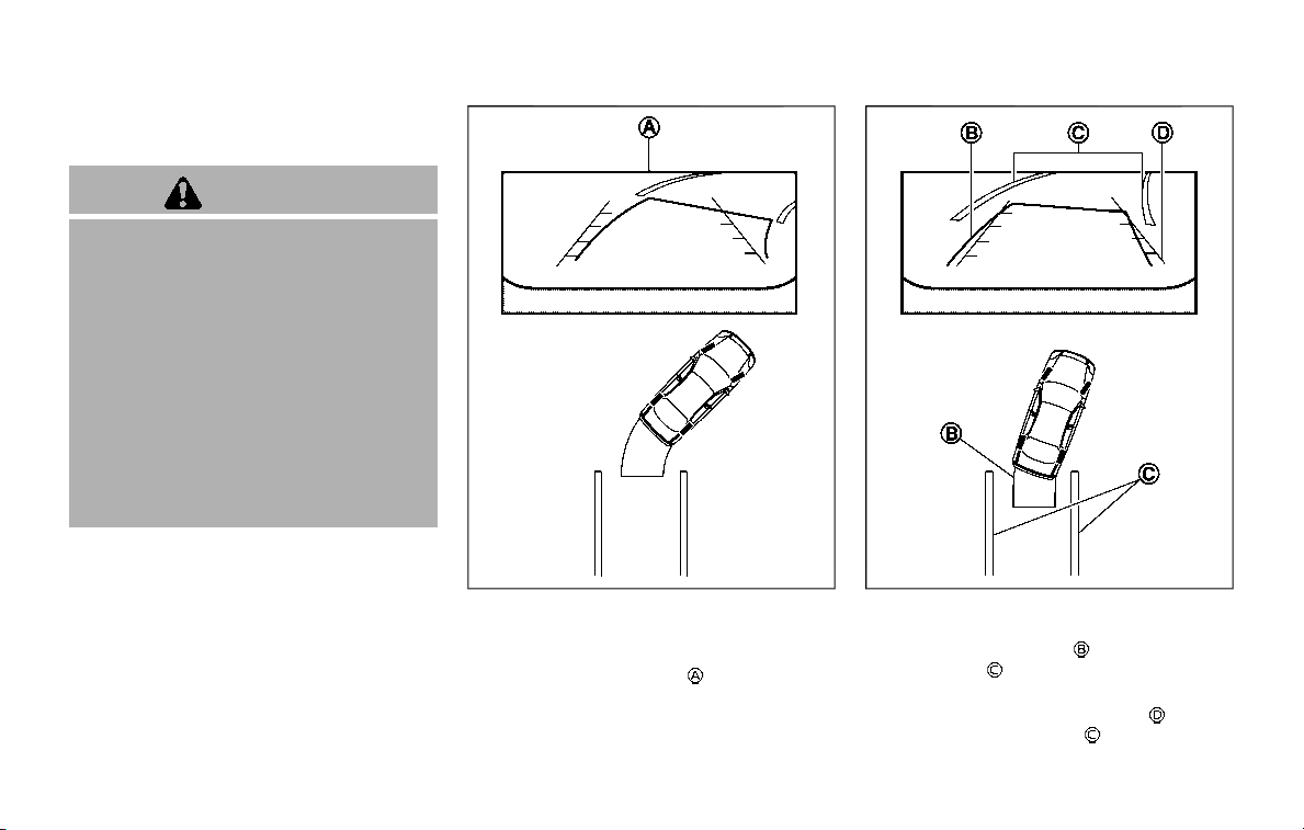
4-18 Monitor, heater, air conditioner, audio, phone and voice recognition systems
How to park with predictive course
lines
WARNING
. If the tires are replaced with
different sized tires, the predic-
tive course lines may be dis-
played incorrectly.
. On a snow-covered or slippery
road, there may be a difference
between the predictive course
line and the actual course line.
. If the battery is disconnected or
becomes discharged, the predic-
tive course lines may be dis-
played incorrectly. If this occurs,
drive the vehicle on a straight
road for more than 5 minutes.
SAA1897
1. Visually check that the parking space
is safe before parking your vehicle.
2. The rear view of the vehicle is dis-
played on the screen
when the shift
lever is moved to the R (Reverse)
position.
SAA1898
3. Slowly back up the vehicle adjusting
the steering wheel so that the pre-
dictive course lines
enter the park-
ing space
.
4. Maneuver the steering wheel to make
the vehicle width guide lines
parallel
to the parking space
while referring
to the predictive course lines.
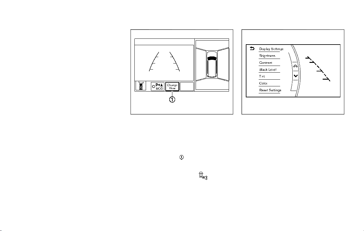
5. When the vehicle is parked in the
space completely, move the shift lever
to the P (Park) position and apply the
parking brake.
WAE0225X
How to switch the display
The Intelligent Around View Monitor can
display two split views as well as a single
view of the front-wide view or rear-wide
view. Push the CAMERA button, change
the shift lever position, or select the
“Change View” key
to switch between
the available views.
For models with the Intelligent Back-up
Intervention (I-BI) system, “
” key may
be displayed on the Intelligent Around
View Monitor screen when the shift lever
is in the R (Reverse) position. For details of
the I-BI system, see “Intelligent Back-up
Intervention (I-BI)” (P.5-53).
JVH1690X
HOW TO ADJUST THE SCREEN VIEW
The display settings such as Brightness,
Contrast, Black Level, Tint and Color of
the Intelligent Around View Monitor can
be adjusted.
1. Push the SETTING button with the
Intelligent Around View Monitor
turned on.
2. The Display settings menu is dis-
played. Select an item you wish to
adjust.
3. Adjust the selected item by touching
the “+” or “-” key.
Select “Reset Settings” key to return all
settings to default.
Monitor, heater, air conditioner, audio, phone and voice recognition systems 4-19

4-20 Monitor, heater, air conditioner, audio, phone and voice recognition systems
NOTE:
Do not adjust any of the display settings
of the Intelligent Around View Monitor
while the vehicle is moving. Make sure
the parking brake is firmly applied.
Display settings menu can also be ac-
cessed while the Intelligent Around View
Monitor screen is not displayed. See
“Intelligent Around View Monitor settings”
(P.4-20).
INTELLIGENT AROUND VIEW MONI-
TOR SETTINGS
To set up the Intelligent Around View
Monitor to your preferred settings, push
the SETTING button while the Intelligent
Around View Monitor screen is not dis-
played, select the “Camera/Sonar” key.
Items displayed on the screen may vary
depending on the specification and mod-
el.

Available setting items:
Setting item Action
Camera Back-up Collision Intervention Intelligent Back-up Intervention (I-BI) system on/off. See “Intelligent Back-up
Intervention (I-BI)” (P.5-53).
Moving Object Detection Turn the MOD system on/off. See “Moving Object Detection (MOD)” (P.4-29).
Non-viewable Area Reminder When this item is turned on, the non-viewable area is highlighted in yellow for
several seconds after the bird’s-eye view is displayed. It will be shown only the
first time after the ignition switch is placed in the ON position.
Predictive Course Lines When this item is turned on, the predictive course lines are displayed in the
front and the rear view and bird’s-eye view.
Automatic Display with Sonar The automatic sonar display can be turned on/off.
Sonar For the information about the sonar, see “Camera aiding sonar function
(models with Intelligent Around View Monitor)” (P.4-25).
Display Brightness Adjust display settings by touching the “+”/“-” key.
Contrast
Black Level
Tint
Color
Reset Settings Return all the settings to default.
Monitor, heater, air conditioner, audio, phone and voice recognition systems 4-21

4-22 Monitor, heater, air conditioner, audio, phone and voice recognition systems
INTELLIGENT AROUND VIEW MONI-
TOR SYSTEM LIMITATIONS
WARNING
Listed below are the system limita-
tions for Intelligent Around View
Monitor. Failure to operate the vehi-
cle in accordance with these system
limitations could result in serious
injury or death.
. Do not use the Intelligent Around
View Monitor with the outside
mirrors in the stored position,
and make sure that the liftgate
is securely closed when operating
the vehicle using the Intelligent
Around View Monitor.
. The apparent distance between
objects viewed on the Intelligent
Around View Monitor differs from
the actual distance.
. The cameras are installed on the
front grille, the outside mirrors
and above the rear license plate.
Do not put anything on the vehi-
cle that covers the cameras.
. When washing the vehicle with
high pressure water, be sure not
to spray it around the cameras.
Otherwise, water may enter the
camera unit causing water con-
densation on the lens, a malfunc-
tion, fire or an electric shock.
. Do not strike the cameras. They
are precision instruments. Doing
so could cause a malfunction or
cause damage resulting in a fire
or an electric shock.
The following are operating limitations
and do not represent a system malfunc-
tion:
. The screen displayed on the Intelligent
Around View Monitor will automati-
cally return to the previous screen 3
minutes after the CAMERA button has
been pushed while the shift lever is in
a position other than the R (Reverse)
position.
. There may be a delay when switching
between views.
. When the temperature is extremely
high or low, the screen may not
display objects clearly.
. When strong light directly shines on
the camera, objects may not be dis-
played clearly.
. The screen may flicker under fluores-
cent light.
. The colors of objects on the Intelligent
Around View Monitor may differ
somewhat from the actual color of
objects.
. Objects on the monitor may not be
clear and the color of the object may
differ in a dark environment.
. There may be differences in sharpness
between each camera view of the
bird’s-eye view.
. When activating the Intelligent Around
View Monitor, the icons and the mes-
sages may not be displayed for a
while.
. If dirt, rain or snow accumulates on
the camera, the Intelligent Around
View Monitor may not display objects
clearly. Clean the camera.
. Do not use wax on the camera lens.
Wipe off any wax with a clean cloth
that has been dampened with a
diluted mild cleaning agent, then wipe
with a dry cloth.
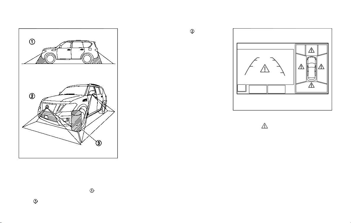
JVH1399X
There are some areas where the system
will not show objects and the system
does not warn of moving objects. When in
the front or the rear view display, an
object below the bumper or on the
ground may not be viewed
. When in
the bird’s-eye view, a tall object near the
seam
of the camera viewing areas will
not appear in the monitor
.
JVH1633X
System temporarily unavailable
When the “ ” icon is displayed on the
screen, there will be abnormal conditions
in the Intelligent Around View Monitor.
This will not hinder normal driving opera-
tion but the system should be inspected.
It is recommended you visit a NISSAN
dealer for inspecting.
Monitor, heater, air conditioner, audio, phone and voice recognition systems 4-23
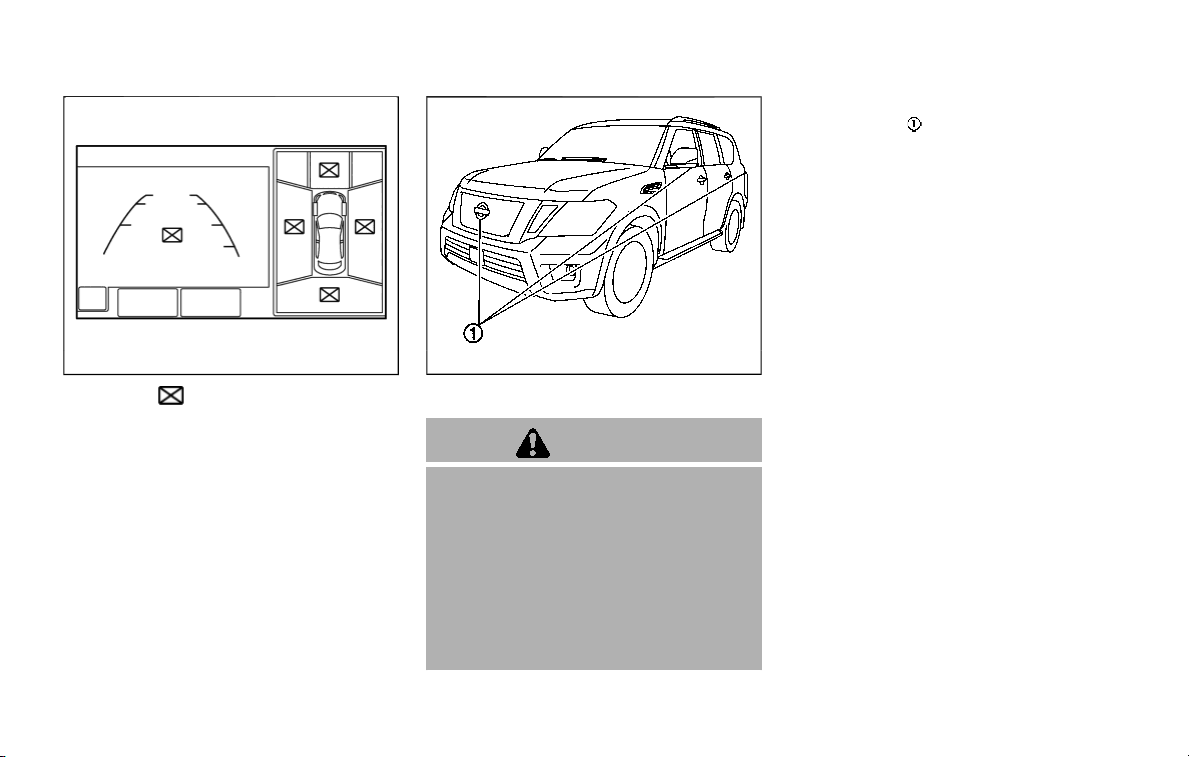
4-24 Monitor, heater, air conditioner, audio, phone and voice recognition systems
JVH1634X
When the “ ” icon is displayed on the
screen, the camera image may be receiv-
ing temporary electronic disturbances
from surrounding devices. This will not
hinder normal driving operation. How-
ever, if it occurs frequently, the system
should be inspected. It is recommended
you visit a NISSAN dealer.
JVH1397X
SYSTEM MAINTENANCE
CAUTION
. Do not use alcohol, benzine or
thinner to clean the camera. This
will cause discoloration. To clean
the camera, wipe with a cloth
dampened with diluted mild
cleaning agent and then wipe
with a dry cloth.
. Do not damage the camera as the
monitor screen may be adversely
affected.
If dirt, rain or snow accumulates on any of
the cameras
, the Intelligent Around
View Monitor may not display objects
clearly. Clean the camera by wiping with
a cloth dampened with a diluted mild
cleaning agent and then wiping with a dry
cloth.
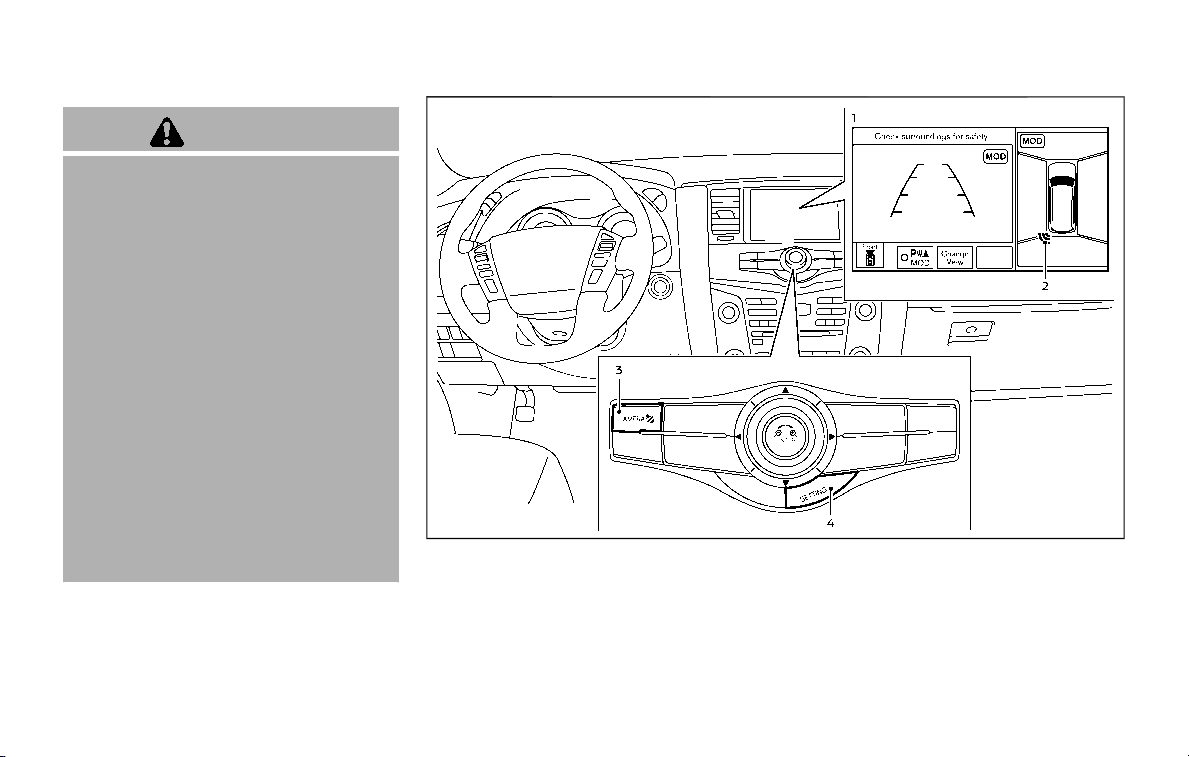
WARNING
Failure to follow the warnings and
instructions for proper use of the
sonar function as outlined in this
section could result in serious injury
or death.
. The sonar is a convenience fea-
ture. It is not a substitute for
proper parking.
. This function is designed as an
aid to the driver in detecting large
stationary objects to help avoid
damaging the vehicle.
. The driver is always responsible
for safety during parking and
other maneuvers.
. Always look around and check
that it is safe to move before
parking.
. Read and understand the limita-
tions of the sonar as contained in
this section.
The sonar function helps to inform the
driver of large stationary objects around
the vehicle when parking by issuing an
audible and visual alert.
WAE0226X
1. Center display
2. Sonar indicator
3. CAMERA button
4. SETTING button
SONAR SYSTEM OPERATION
The system gives the tone for front
objects when the shift lever is in the D
(Drive) position and both front and rear
objects when the shift lever is in the R
(Reverse) position.
When the camera image is shown on the
Monitor, heater, air conditioner, audio, phone and voice recognition systems 4-25
CAMERA AIDING SONAR FUNCTION (models
with Intelligent Around View Monitor)
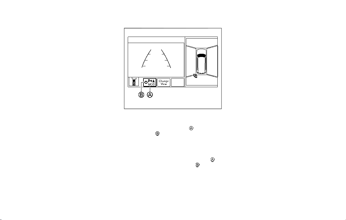
4-26 Monitor, heater, air conditioner, audio, phone and voice recognition systems
center display, the system shows the
sonar indicator regardless of the shift
lever position.
The system is deactivated at speeds
above 6 MPH (10 km/h). It is reactivated
at lower speeds.
The colors of the sonar indicators and the
distance guide lines in the front, front-
wide, rear and rear-wide views indicate
different distances to the object.
When the objects are detected, the in-
dicator (green) appears and blinks and
the tone sounds intermittently. When the
vehicle moves closer to the object, the
color of the indicator turns yellow and the
rate of the blinking and the rate of the
tone increase. When the vehicle is very
close to the object, the indicator stops
blinking and turns red, and the tone
sounds continuously.
The intermittent tone will stop after 3
seconds when an object is detected by
only the sonar and the distance does not
change.
The tone will stop when the object is no
longer near the vehicle.
WAE0227X
TURNING ON AND OFF THE SONAR
FUNCTION
When the Sonar/MOD key is selected,
the indicator
will turn off and the sonar
will be turned off temporarily. The Moving
Object Detection (MOD) system will also
be turned off at the same time. (See
“Moving Object Detection (MOD)” (P.4-
29).) When the Sonar/MOD key
is
selected again, the indicator
will turn
on and the sonar will turn back on.
In the below cases, the sonar will be
turned back on automatically:
. When the shift lever is in the R
(Reverse) position.
. When the CAMERA button is pushed
and a screen other than the camera
view is shown on the display.
. When vehicle speed decreases below
approximately 6 MPH (10 km/h).
. When the ignition switch is placed in
the OFF position and turned back to
the ON position again.
To deactivate the sonar system comple-
tely, use the “Sonar” settings. See “Sonar
function settings” (P.4-27).
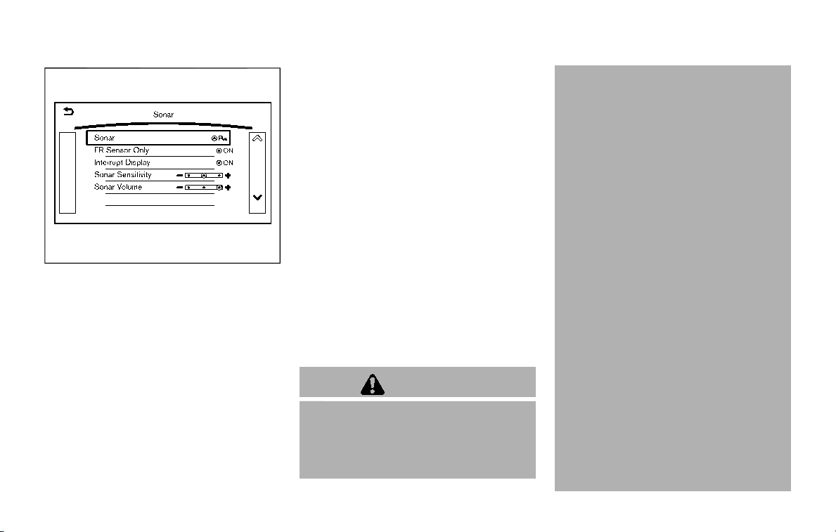
JVH1695X
Sonar function settings
To set up the sonar function to your
preferred settings, push the SETTING
button, select the “Camera/Sonar” key
and then select the “Sonar” key on the
center display.
Designs and items displayed on the
screen may vary depending on the mod-
els.
Sonar:
When this item is turned on, the front and
rear sonar is activated. When this item is
turned off (indicator turns off), the front
and rear sonar is deactivated. The amber
markers are displayed at the corners of
the vehicle icon and the sonar icon will
disappear from the Sonar/MOD key. The
next time the ignition switch is placed in
the ON position, “Sonar is OFF” is dis-
played briefly.
FR Sensor Only:
When this item is turned on, only the front
sonar is activated. The amber markers are
displayed at the rear corners of the
vehicle icon.
Interrupt Display:
When this item is turned on, the Intelligent
Around View Monitor will interrupt the
current view in the display to see the
surrounding area of the vehicle.
Sonar Sensitivity:
Adjust the sensitivity level of the sonar.
Sonar Volume:
Adjust the tone volume of the sonar.
SONAR SYSTEM LIMITATIONS
WARNING
Listed below are the system limita-
tions for the sonar function. Failure
to operate the vehicle in accordance
with these system limitations could
result in serious injury or death.
. Inclement weather or ultrasonic
sources such as an automatic car
wash, a truck’s compressed-air
brakes or a pneumatic drill may
affect the function of the system,
including reduced performance
or a false activation.
. This function is designed as an
aid to the driver in detecting large
stationary objects to help avoid
damaging the vehicle.
. The system is not designed to
prevent contact with small or
moving objects.
. The system will not detect small
objects below the bumper, and
may not detect objects close to
the bumper or on the ground.
. The system may not detect the
following objects:
— Fluffy objects such as snow,
cloth, cotton, grass or wool.
— Thin objects such as rope, wire
or chain.
— Wedge-shaped objects.
. If your vehicle sustains damage
to the bumper fascia, leaving it
misaligned or bent, the sensing
zone may be altered causing in-
accurate measurement of objects
Monitor, heater, air conditioner, audio, phone and voice recognition systems 4-27

4-28 Monitor, heater, air conditioner, audio, phone and voice recognition systems
or false alarms.
CAUTION
Excessive noise (such as audio sys-
tem volume or an open vehicle win-
dow) will interfere with the tone and
it may not be heard.
SYSTEM TEMPORARILY UNAVAIL-
ABLE
When the amber markers are displayed at
the corners of the vehicle icon and the
function cannot be activated from the
“Sonar” settings (the setting items are
grayed out), the sonar system may be
malfunctioning.
SYSTEM MAINTENANCE
CAUTION
Keep the surface of the sonar sen-
sors (located on the front and rear
bumper fascia) free from accumula-
tions of snow, ice and dirt. Do not
scratch the surface of the sonar
sensors when cleaning. If the sen-
sors are covered, the accuracy of the
sonar function will be diminished.
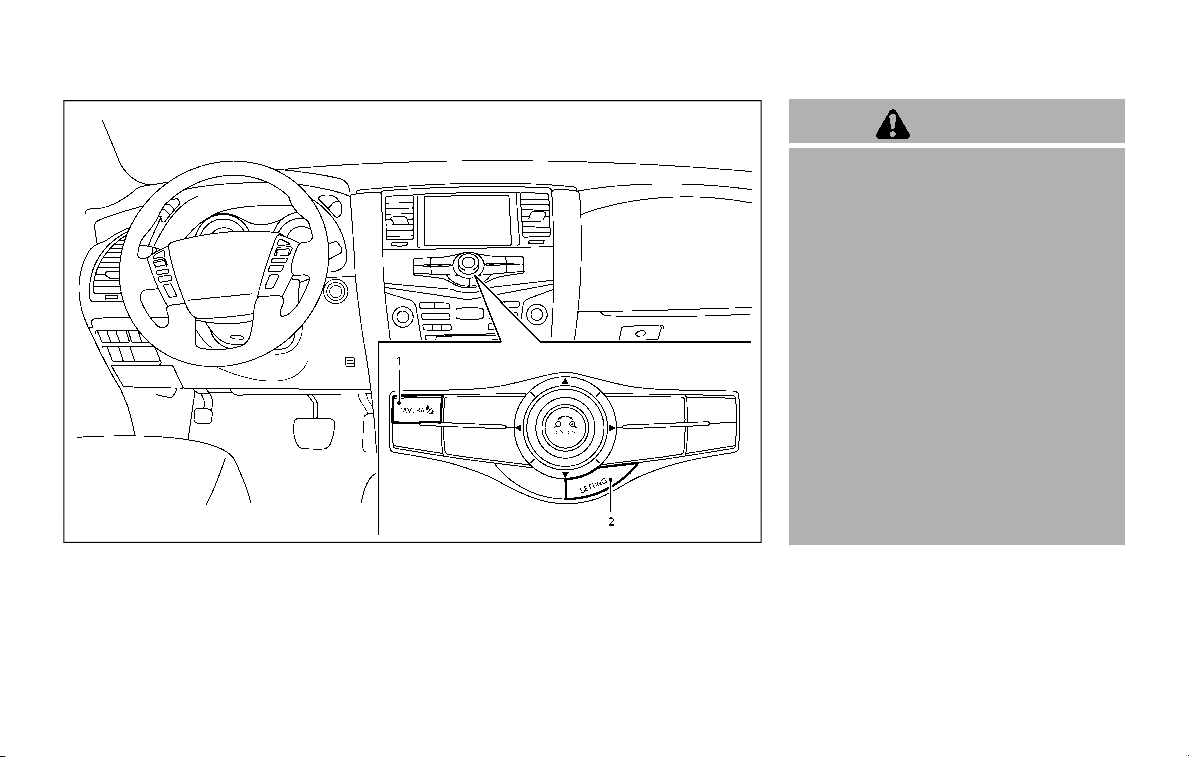
JVH1689X
1. CAMERA button
2. SETTING button
WARNING
Failure to follow the warnings and
instructions for proper use of the
Moving Object Detection system
could result in serious injury or
death.
. The MOD system is not a substi-
tute for proper vehicle operation
and is not designed to prevent
contact with the objects sur-
rounding the vehicle. When man-
euvering, always use the outside
mirror and rearview mirror and
turn and check the surrounding
to ensure it is safe to maneuver.
. The system is deactivated at
speeds above 6 MPH (10 km/h).
It is reactivated at lower speeds.
. The MOD system is not designed
to detect the surrounding sta-
tionary objects.
The Moving Object Detection (MOD) sys-
tem can inform the driver of the moving
objects surrounding the vehicle when
driving out of garages, maneuvering into
parking lots and in other such instances.
The MOD system detects moving objects
by using image processing technology on
Monitor, heater, air conditioner, audio, phone and voice recognition systems 4-29
MOVING OBJECT DETECTION (MOD)
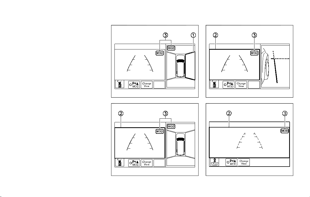
4-30 Monitor, heater, air conditioner, audio, phone and voice recognition systems
the image shown on the display.
MOD SYSTEM OPERATION
The MOD system will turn on automati-
cally under the following conditions:
. When the shift lever is in the R
(Reverse) position.
. When vehicle speed decreases below
approximately 5 MPH (8 km/h).
WAE0228X
Bird’s-eye view
WAE0229X
Front view / rear view
JVH1698X
Rear and front-side views
JVH1699X
Front-wide view / rear-wide view
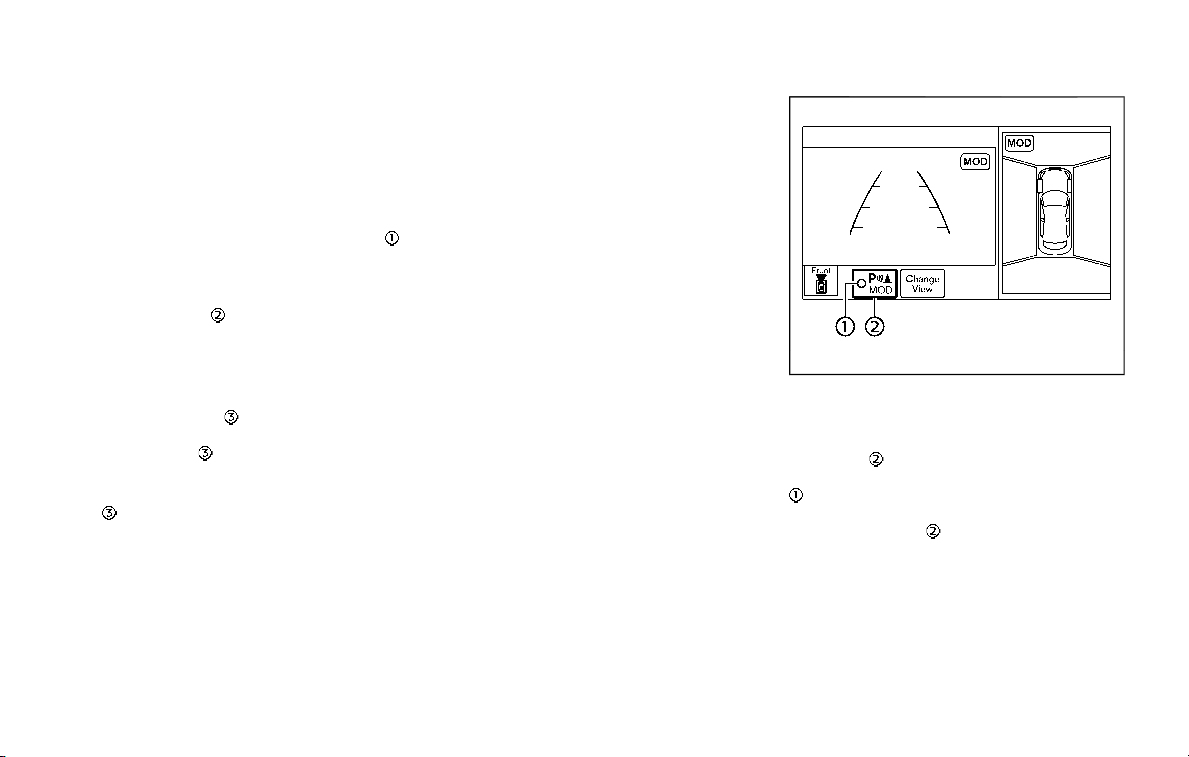
When the MOD system detects moving
objects near the vehicle, the yellow frame
will be displayed on the view where the
objects are detected and a chime will
sound once. While the MOD system con-
tinues to detect moving objects, the
yellow frame continues to be displayed.
In the bird’s-eye view, the yellow frame
is displayed on each camera image (front,
rear, right, left) depending on where
moving objects are detected.
The yellow frame
is displayed on each
view in the front view, front-wide view,
rear view and rear-wide view modes.
While the sonar is beeping, the MOD
system does not chime.
A green MOD icon
is displayed in the
view where the MOD system is operative.
A gray MOD icon
is displayed in the view
where the MOD system is not operative.
If the MOD system is turned off, the MOD
icon
is not displayed.
The MOD system operates in the follow-
ing conditions when the camera view is
displayed:
. When the shift lever is in the P (Park) or
N (Neutral) position and the vehicle is
stopped, the MOD system detects the
moving objects in the bird’s-eye view.
. When the shift lever is in the D (Drive)
position and the vehicle speed is
below approximately 5 MPH (8 km/h),
the MOD system detects moving ob-
jects in the front view or front-wide
view.
. When the shift lever is in the R
(Reverse) position and the vehicle
speed is below approximately 5 MPH
(8 km/h), the MOD system detects
moving objects in the rear view or
rear-wide view. The MOD system will
not operate if the liftgate is open.
The MOD system does not detect moving
objects in the front-side view. The MOD
icon is not displayed on the screen when
in front-side view.
JVH1712X
TURNING ON AND OFF THE MOD
SYSTEM
When the MOD is active and the Sonar/
MOD key
is selected, the MOD system
will turn off temporarily and the indicator
will turn off. (A camera-aiding sonar will
turn off at the same time.) When the
Sonar/MOD key
is selected again, the
indicator will turn on and the MOD system
will turn back on.
To enable or disable the MOD, use the
“Camera” menu. See “MOD function
setting” (P.4-32).
Monitor, heater, air conditioner, audio, phone and voice recognition systems 4-31

4-32 Monitor, heater, air conditioner, audio, phone and voice recognition systems
MOD function setting
To set up the MOD function to your
preferred settings, push the SETTING
button, select “Camera/Sonar” key, and
then select the “Camera” key on the
center display.
JVH1713X
Moving Object Detection:
When this item is turned on, the MOD is
activated. When this item is turned off
(indicator turns off), the MOD system is
deactivated. When the MOD system is
deactivated, “MOD”
will disappear on
the Sonar/MOD key
and the MOD icon
will disappear as well.
When the sonar is turned off on the
setting menu as well, the Sonar/MOD
key
will disappear.
MOD SYSTEM LIMITATIONS
WARNING
Listed below are the system limita-
tions for MOD. Failure to operate the
vehicle in accordance with these
system limitations could result in
serious injury or death.
. Do not use the MOD system when
towing a trailer. The system may
not function properly.
. Excessive noise (for example,
audio system volume or open
vehicle window) will interfere
with the chime sound, and it
may not be heard.
. The MOD system performance
will be limited according to en-
vironmental conditions and sur-
rounding objects such as:
— When there is low contrast
between background and the
moving objects.
— When there is blinking source
of light.
— When strong light such as
another vehicle’s headlight or
sunlight is present.
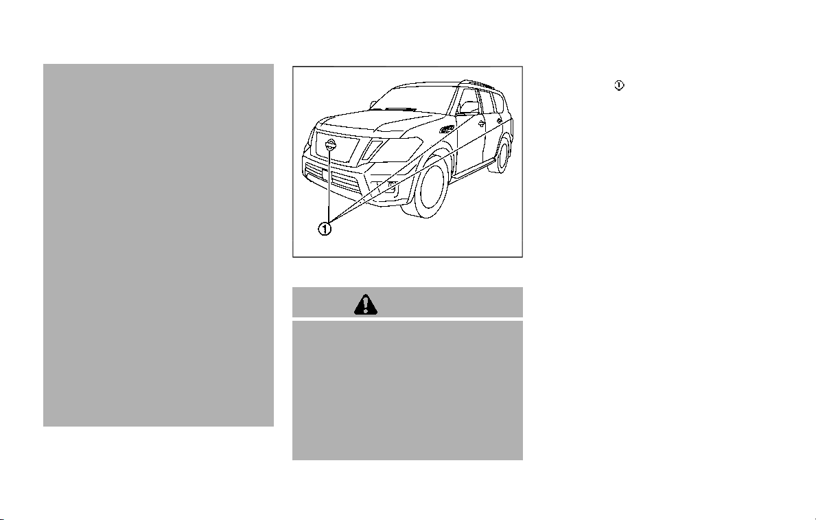
— When camera orientation is
not in its usual position, such
as when mirror is folded.
— When there is dirt, water drops
or snow on the camera lens.
— When the position of the mov-
ing objects in the display is
not changed.
. The MOD system might detect
flowing water droplets on the
camera lens, white smoke from
the muffler, moving shadows, etc.
. The MOD system may not func-
tion properly depending on the
speed, direction, distance or
shape of the moving objects.
. If your vehicle sustains damage
to the parts where the camera is
installed, leaving it misaligned or
bent, the sensing zone may be
altered and the MOD system may
not detect objects properly.
. When the temperature is extre-
mely high or low, the screen may
not display objects clearly. This is
not a malfunction.
JVH1397X
SYSTEM MAINTENANCE
CAUTION
. Do not use alcohol, benzine or
thinner to clean the camera. This
will cause discoloration. To clean
the camera, wipe with a cloth
dampened with diluted mild
cleaning agent and then wipe
with a dry cloth.
. Do not damage the camera as the
monitor screen may be adversely
affected.
If dirt, rain or snow accumulates on any of
the cameras
, the MOD system may not
operate properly. Clean the camera by
wiping with a cloth dampened with a
diluted mild cleaning agent and then
wiping with a dry cloth.
Monitor, heater, air conditioner, audio, phone and voice recognition systems 4-33
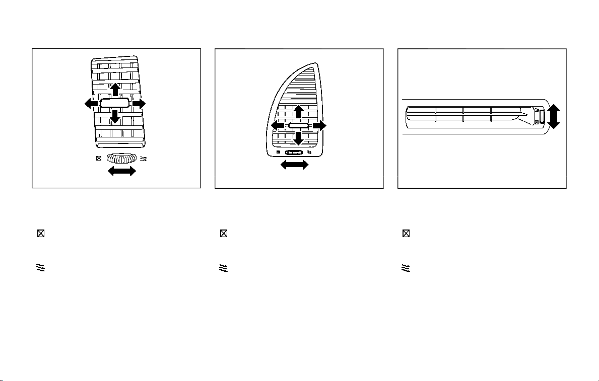
4-34 Monitor, heater, air conditioner, audio, phone and voice recognition systems
SAA3348
CENTER VENTILATORS
Open/close the ventilators by moving the
control to either direction.
: This symbol indicates that the venti-
lators are closed. Moving the side
control to this direction will close the
ventilators.
: This symbol indicates that the venti-
lators are open. Moving the side
control to this direction will open the
ventilators.
Adjust the air flow direction of the venti-
lators by moving the center knob (up/
down, left/right) until the desired position
is achieved.
SAA3054
SIDE VENTILATORS
Open/close the ventilators by moving the
control to either direction.
: This symbol indicates that the venti-
lators are closed. Moving the side
control to this direction will close the
ventilators.
: This symbol indicates that the venti-
lators are open. Moving the side
control to this direction will open the
ventilators.
Adjust the air flow direction of the venti-
lators by moving the center knob (up/
down, left/right) until the desired position
is achieved.
JVH1313X
REAR VENTILATORS
Open/close the ventilators by moving the
control to either direction.
: This symbol indicates that the venti-
lators are closed. Moving the side
control to this direction will close the
ventilators.
: This symbol indicates that the venti-
lators are open. Moving the side
control to this direction will open the
ventilators.
VENTILATORS
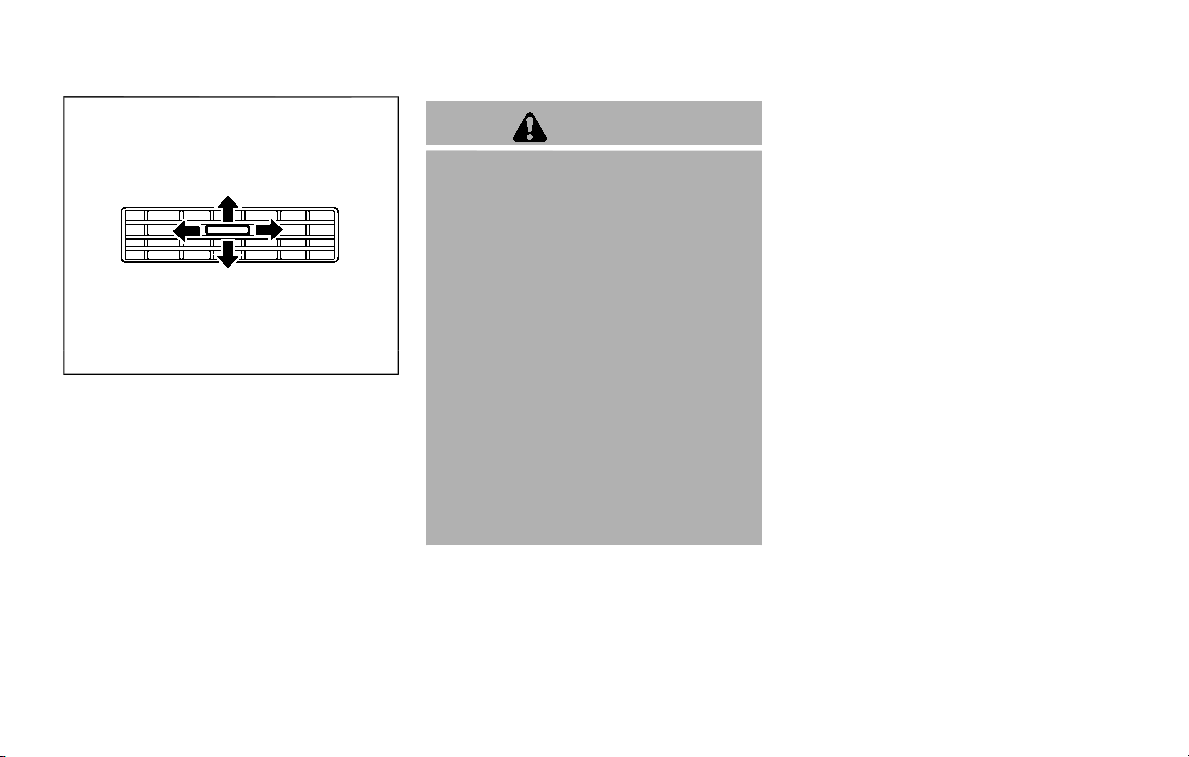
SAA3055
Adjust the air flow direction of the venti-
lators by moving the center knob (up/
down, left/right) until the desired position
is achieved.
WARNING
. The air conditioner cooling func-
tion operates only when the en-
gine is running.
. Do not leave children or adults
who would normally require the
support of others alone in your
vehicle. Pets should not be left
alone either. On hot, sunny days,
temperatures in a closed vehicle
could quickly become high en-
ough to cause severe or possibly
fatal injuries to people or animals.
. Do not use the recirculation mode
for long periods as it may cause
the interior air to become stale
and the windows to fog up.
. Do not adjust the heating and air
conditioning controls while driv-
ing so that full attention may be
given to vehicle operation.
Start the engine and operate the heater
and air conditioner system.
NOTE:
. Odors from inside and outside the
vehicle can build up in the air condi-
tioner unit. Odor can enter the pas-
senger compartment through the
vents.
. When parking, set the heater and air
conditioner controls to turn off air
recirculation to allow fresh air into
the passenger compartment. This
should help reduce odors inside the
vehicle.
Monitor, heater, air conditioner, audio, phone and voice recognition systems 4-35
HEATER AND AIR CONDITIONER
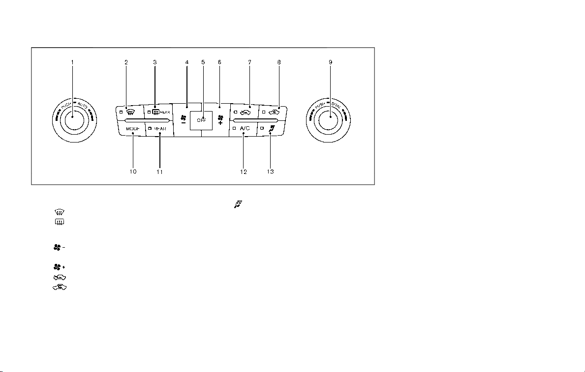
4-36 Monitor, heater, air conditioner, audio, phone and voice recognition systems
SAA3059
1. “AUTO” button/Temperature control dial
(driver’s side)
2. “
” front defroster button
3. “
” rear window defroster button (See
“Rear window and outside mirror defros-
ter switch” (P.2-36).)
4. “
” fan speed decrease button
5. “OFF” button
6. “
” fan speed increase button
7. “
” outside air circulation button
8. “
” air recirculation button
9. “DUAL” zone control ON/OFF button/
Temperature control dial (passenger’s
side)
10. “MODE” manual air flow control button
11. “REAR” control button
12. “A/C” air conditioner ON/OFF button
13. “
” upper vent button
AUTOMATIC AIR CONDITIONER
Automatic operation
Cooling and/or dehumidified heating
(AUTO):
This mode may be used all year round.
The system works automatically to con-
trol the inside temperature, air flow dis-
tribution and fan speed after the
preferred temperature is set manually.
1. Push the “AUTO” button on. (The
indicator on the button will illuminate
and AUTO will be displayed.)
2. Turn the temperature control dial
(driver’s side) to set the desired tem-
perature.
The temperature of the passenger
compartment will be maintained
automatically. Air flow distribution
and fan speed will also be controlled
automatically.
3. You can individually set driver and
front passenger’s side temperature
using each temperature control but-
ton. When the “DUAL” button is pushed
or the passenger’s side temperature
control button is turned, the DUAL
indicator will come on. To turn off the
passenger’s side temperature control,
push the “DUAL” button.
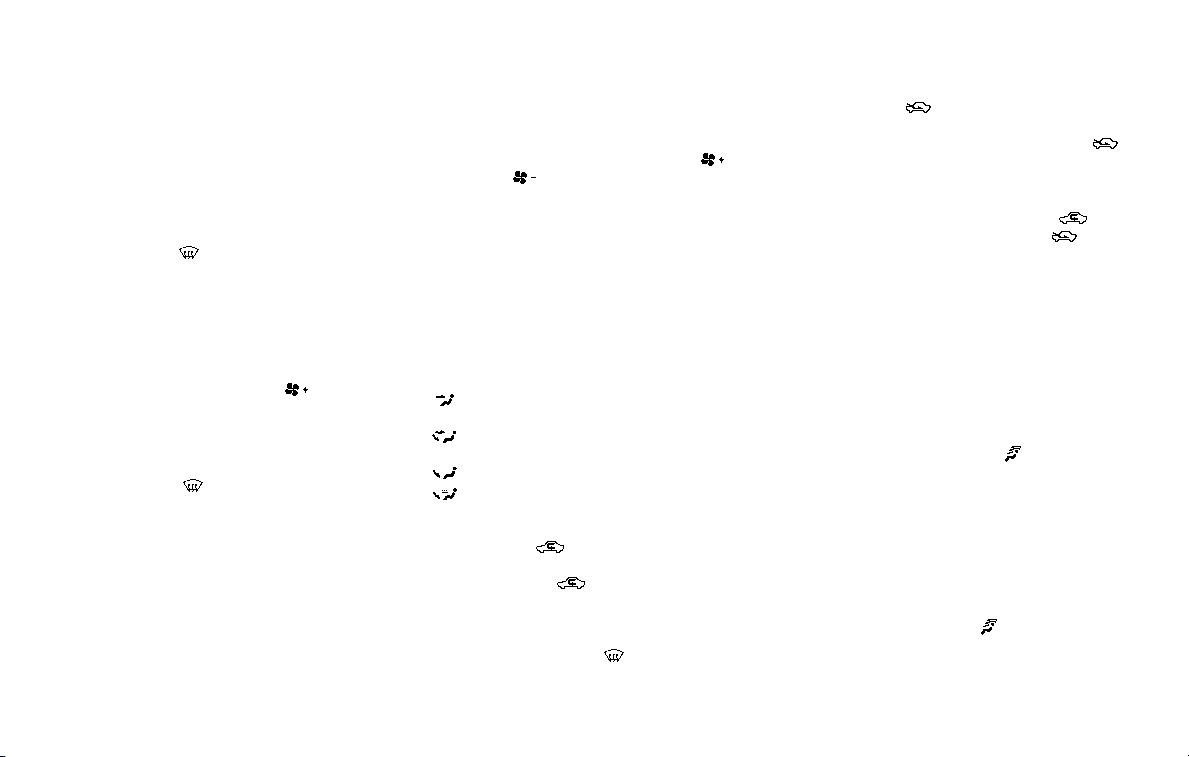
4. To turn off the heater and air condi-
tioner system, push the “OFF” button.
A visible mist may be seen coming from
the ventilators in hot, humid conditions as
the air is cooled rapidly. This does not
indicate a malfunction.
Dehumidified defrosting or defogging:
1. Push the “
” front defroster button.
(The indicator light on the button will
illuminate.)
2. Turn the temperature control dial to
set the desired temperature.
. To quickly remove ice from the out-
side of the windows, push the fan
speed increase button “
” and set it
to the maximum position.
. As soon as possible after the wind-
shield is clean, push the “AUTO” button
to return to the auto mode.
. When the “
” front defroster button
is pushed, the air conditioner will
automatically be turned on at outside
temperatures above 23°F (−5°C) to
defog the windshield, and the air
recirculate mode will automatically
be turned off.
Outside air is drawn into the passen-
ger compartment to improve the
defogging performance.
Manual operation
Fan speed control:
Push the fan speed increase “
”or
decrease “
” buttons to manually con-
trol the fan speed.
Push the “AUTO” button to return to
automatic control of the fan speed.
Temperature control:
Turn the temperature control dial to set
the desired temperature.
Air flow control:
Pushing the “MODE” manual air flow
control button selects the air outlet to:
: Air flows from center and side ventila-
tors.
: Air flows from center and side ventila-
tors and foot outlets.
: Air flows mainly from foot outlets.
: Air flows from defroster and foot outlets.
Air intake control:
. Push the “
” air recirculation button
to recirculate interior air inside the
vehicle. The “
” indicator light on the
button will come on. The air recircula-
tion mode cannot be activated when
the air conditioner is in the front
defrosting mode “
”.
. Push the “
” outside air circulation
button to draw outside air into the
passenger compartment. The “
”
indicator light on the button will come
on.
. To control the air intake automatically,
push and hold either the “
” air
recirculation button or the “
” out-
side air circulation button (whichever
indicator light is illuminated). The
indicator lights (both air recirculation
and outside air circulation buttons)
will flash twice, and then the air intake
will switch to automatic control.
Turning the system off
Push the OFF button.
Upper vent system
When the upper vent “ ” button is
pushed, the air flow against the driver’s
or passenger’s upper body becomes gen-
tle. The indicator light on the button will
illuminate.
In this mode, air from the upper ventilator
flows in order to control the cabin tem-
perature without blowing air directly on
the occupants.
Push the upper vent “
” button when
you want the air conditioner to work
quickly.
To turn the system off, push the upper
Monitor, heater, air conditioner, audio, phone and voice recognition systems 4-37
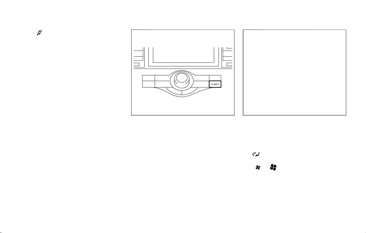
4-38 Monitor, heater, air conditioner, audio, phone and voice recognition systems
vent “ ” button to turn the indicator
light off.
JVH1630X
Operations on touch panel screen
Heater and air conditioner can be oper-
ated on the touch panel screen. Push the
“CLIMATE” button on the center multi-
function control panel and turn the dis-
play to the Climate screen.
For details of the touch panel screen
operation, see the separate NissanCon-
nect® Owner’s Manual.
JVH1720X
The following operations are available
with the touch panel screen.
Availability of the item depends on the
model and specifications.
Available items:
.
Touch to change the air flow mode.
. -
/ +
Touch to change the fan speed of the
air from the ventilators.
. Rear Climate
Touch to display the Rear Climate
screen. (See “Rear automatic air con-
ditioning system” (P.4-39).)
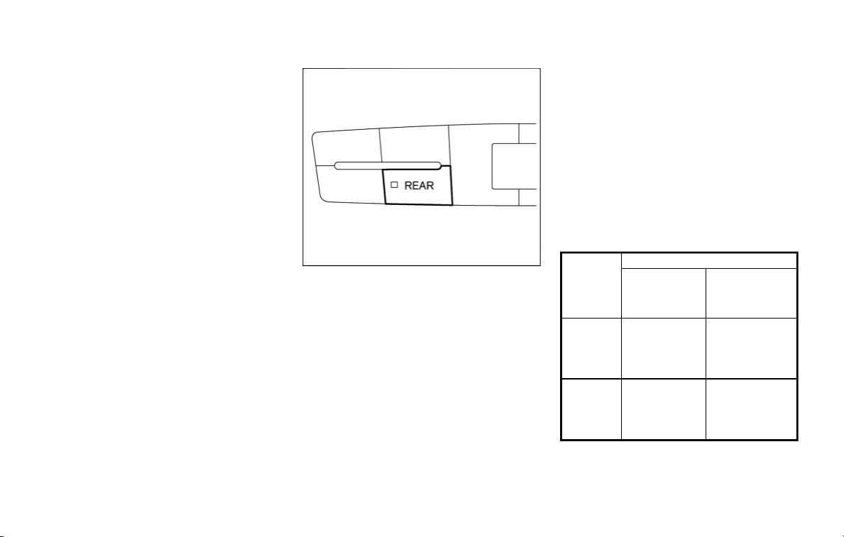
. A/C
Touch to turn the air conditioner on/
off.
. DUAL
Touch to turn the DUAL mode (pas-
senger’s side temperature control)
on/off.
. Upper Vent
Touch to turn the upper vent system
on/off. (See “Upper vent system” (P.4-
37).)
JVH1621X
REAR AUTOMATIC AIR CONDITION-
ING SYSTEM
Push the “REAR” button on the front air
conditioner control panel to turn on the
rear automatic air conditioning system.
(The REAR indicator light will illuminate.)
To control the rear automatic air con-
ditioning system with the front air condi-
tioner control panel, push the “CLIMATE”
button on the center multi-function con-
trol panel and touch “Rear Climate” key.
The display will switch to the Rear Climate
screen.
The rear automatic air conditioning sys-
tem can be adjusted with the front air
conditioner control panel when the Rear
Climate screen is displayed.
Push the “CLIMATE” button one more
time, the display will return to the Climate
screen.
The rear automatic air conditioning sys-
tem can also be adjusted by using the
rear air conditioner control panel located
on the rear of the center console. (See
“Rear air conditioner control panel opera-
tion” (P.4-42).)
This table shows the relation between the
front air conditioner control panel and
the rear air conditioner control panel.
Display status
Rear Climate
screen is dis-
played
Rear Climate
screen is not
displayed (Cli-
mate screen)
Front air
condition-
er control
panel
Only the rear
automatic air
conditioning
system can be
operated
Only the front
air conditioner
can be operated
Rear air
condition-
er control
panel
Cannot be op-
erated
Only the rear
automatic air
conditioning
system can be
operated
Monitor, heater, air conditioner, audio, phone and voice recognition systems 4-39

4-40 Monitor, heater, air conditioner, audio, phone and voice recognition systems
Front air conditioner control panel
operation
Automatic operation:
1. Push the “REAR” button to turn on rear
automatic air conditioning system.
Push the “CLIMATE” button on the
center multi-function control panel
and select the “Rear Climate” key to
display the Rear Climate screen.
2. Push the “AUTO” button. (The AUTO
indicator light will illuminate and
“AUTO” will appear on the display.)
3. Turn the temperature control dial
(driver’s side) to set the desired tem-
perature.
Cooling and dehumidified heating:
1. Push the “REAR” button to turn on the
rear automatic air conditioning sys-
tem. Push the “CLIMATE” button on
the center multi-function control pa-
nel and touch “Rear Climate” key to
display the Rear Climate screen.
2. Turn the temperature control dial
(driver’s side) to set the desired tem-
perature.
3. Switch the air flow mode to
by
pushing the “MODE” button.
4. Push the “CLIMATE” button on the
center multi-function control panel
one more time to return to the
Climate screen. If the A/C indicator
light does not illuminate, push the
“A/C” button. (The A/C indicator light
will turn on.)
NOTE:
When the front air conditioner is off, the
rear automatic air conditioning system
only operates the fan. When you would
like to use the air conditioner, be sure to
push the “A/C” button on the front air
conditioner control panel to turn on the
A/C indicator light.
Manual operation:
. Temperature control
Turn the temperature control dial
(driver’s side) to set the desired tem-
perature.
. Fan speed control
Push the fan speed control “
”
button or “
” button to manually
control the fan speed.
. Air flow control
Push the “MODE” button to change the
air flow mode.
: The air outlet is fixed at foot level.
: The air outlet is fixed at both the head
and foot levels.
: The air outlet is fixed at the head level.
Touch panel operation
The rear automatic air conditioning sys-
tem can also be controlled on the Rear
Climate screen.
Touch the “Rear Climate” key on the
Climate screen to display the Rear Cli-
mate screen.
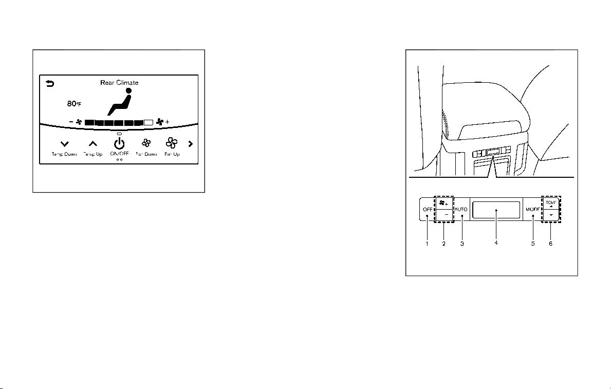
JVH1719X
Rear Climate screen
Available items:
. Temp Down
Touch to decrease the temperature
setting.
. Temp Up
Touch to increase the temperature
setting.
. ON/OFF
Touch to turn the rear automatic air
conditioning system on/off.
. Fan Down
The fan speed of the air from the
ventilators can be decreased.
. Fan Up
The fan speed of the air from the
ventilators can be increased.
. Auto
Touch to turn the auto mode on/off.
. Mode
Touch to select different air flow
mode.
SAA3327
1. “OFF” button
2. Fan speed control button
3. “AUTO” button
4. Display
5. “MODE” button
6. “TEMP” button
Monitor, heater, air conditioner, audio, phone and voice recognition systems 4-41
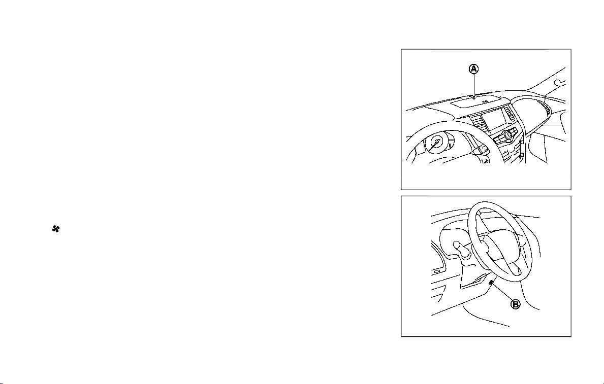
4-42 Monitor, heater, air conditioner, audio, phone and voice recognition systems
Rear air conditioner control panel
operation
Rear control buttons:
The rear seat passengers can adjust the
rear automatic air conditioning system
using the control switches on the rear of
the center console.
The rear control buttons do not function
when the Rear Climate screen is shown
on the front display. To activate the rear
control buttons, push the “CLIMATE” but-
ton on the center multi-function control
panel and switch the screen to the
Climate screen.
. “OFF” button:
Rear automatic air conditioning sys-
tem off.
. “
” button:
Rear fan speed control up/down
. “AUTO” button:
Rear automatic air conditioning sys-
tem on, AUTO mode on
. “MODE” button:
Rear air flow control change
. “TEMP” button:
Rear temperature control up/down
Turning the system off
Use the following methods to turn the
rear automatic air conditioning system
off.
. Operating the front air conditioner
control panel:
Push the “OFF” button on the front air
conditioner control panel when the
Rear Climate screen is displayed.
. Operating the Rear Climate screen:
Touch the “ON/OFF” key on the Rear
Climate screen when the rear auto-
matic air conditioning system is on.
. Operating the rear air conditioner
control panel:
Push the “OFF” button on the rear air
conditioner control panel when the
Rear Climate screen is not displayed.
SAA3088
SAA3058

OPERATING TIPS
When the engine coolant temperature
and outside air temperature are low, the
air flow from the foot outlets may not
operate. However, this is not a malfunc-
tion. After the coolant temperature
warms up, the air flow from the foot
outlets will operate normally.
The sensors
and located on the
instrument panel help maintain a con-
stant temperature. Do not put anything
on or around the sensors.
LINKING INTELLIGENT KEY (if so
equipped)
The air conditioner system settings can
be memorized for each Intelligent Key.
For more details, see “Setting memory
function” (P.3-42).
IN-CABIN MICROFILTER
The air conditioner system is equipped
with an in-cabin microfilter which collects
dirt, pollen, dust, etc.
To make sure the air conditioner heats,
defogs, and ventilates efficiently, replace
the filter in accordance with the specified
maintenance intervals listed in the “9.
Maintenance and schedules” section. It is
recommended to see a NISSAN dealer to
replace the filter.
The filter should be replaced if the air
flow decreases significantly or if win-
dows fog up easily when operating the
heater or air conditioner.
SERVICING AIR CONDITIONER
The air conditioner system in your NISSAN
is charged with a refrigerant designed
with the environment in mind. This re-
frigerant will not harm the earth’s
ozone layer. However, special charging
equipment and lubricant are required
when servicing your NISSAN air condi-
tioner. Using improper refrigerants or
lubricants will cause severe damage to
your air conditioner system. (See “Capa-
cities and recommended fluids/lubri-
cants” (P.10-2) for air conditioner system
refrigerant and lubricant recommenda-
tions.)
Your NISSAN dealer will be able to service
your environmentally friendly air condi-
tioner system.
WARNING
The system contains refrigerant un-
der high pressure. To avoid personal
injury, any air conditioner service
should be done only by an experi-
enced technician with the proper
equipment.
WINDOW ANTENNA
The antenna pattern is printed inside the
rear side glass.
CAUTION
. Do not place metalized film near
the 3rd row seat window or at-
tach any metal parts to it. This
may cause poor reception or
noise.
. When cleaning the inside of the
rear side window, be careful not
to scratch or damage the rear
side window antenna. Lightly
wipe along the antenna with a
dampened soft cloth.
Monitor, heater, air conditioner, audio, phone and voice recognition systems 4-43
ANTENNA
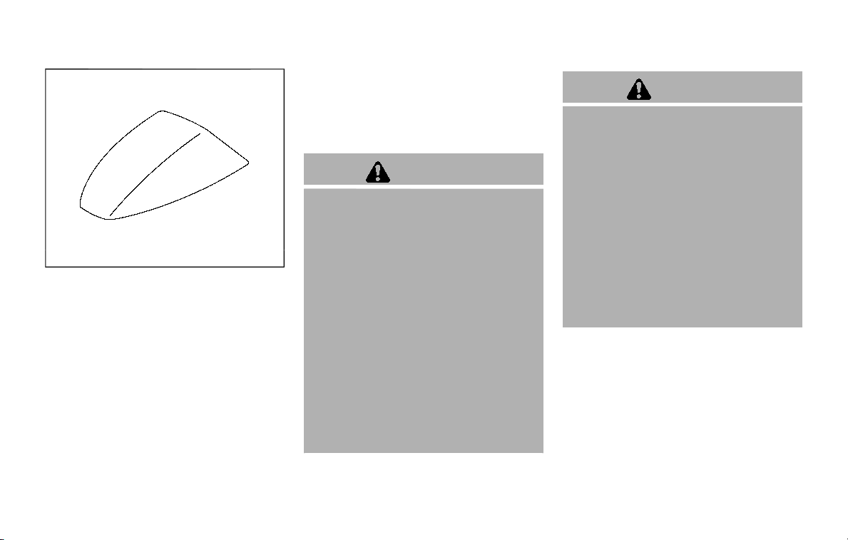
4-44 Monitor, heater, air conditioner, audio, phone and voice recognition systems
SAA3602
SATELLITE ANTENNA
There is a satellite antenna on the rear
part of the vehicle roof.
When installing a car phone or a CB radio
in your vehicle, be sure to observe the
following cautions, otherwise the new
equipment may adversely affect the elec-
tronic control modules and electronic
control system harness.
WARNING
. A cellular phone should not be
used for any purpose while driv-
ing so full attention may be given
to vehicle operation. Some juris-
dictions prohibit the use of cellu-
lar phones while driving.
. If you must make a call while your
vehicle is in motion, the hands-
free cellular phone operational
mode (if so equipped) is highly
recommended. Exercise extreme
caution at all times so full atten-
tion may be given to vehicle
operation.
. If a conversation in a moving
vehicle requires you to take
notes, pull off the road to a safe
location and stop your vehicle
before doing so.
CAUTION
. Keep the antenna as far away as
possible from the electronic con-
trol modules.
. Keep the antenna wire more than
8 in (20 cm) away from the
electronic control system har-
ness. Do not route the antenna
wire next to any harness.
. Adjust the antenna standing-
wave ratio as recommended by
the manufacturer.
. Connect the ground wire from the
CB radio chassis to the body.
. For details, it is recommended
you visit a NISSAN dealer.
CAR PHONE OR CB RADIO

5 Starting and driving
Precautions when starting and driving ...................... 5-4
Exhaust gas (carbon monoxide) ................................ 5-4
Three-way catalyst ............................................................... 5-4
Tire Pressure Monitoring System (TPMS) ........... 5-5
Avoiding collision and rollover .................................... 5-8
On-pavement and off-road driving
precautions ................................................................................. 5-9
Off-road recovery .................................................................. 5-9
Rapid air pressure loss ...................................................... 5-9
Drinking alcohol/drugs and driving ..................... 5-10
Driving safety precautions .......................................... 5-10
Push-button ignition switch ............................................. 5-13
Operating range for engine start function ...... 5-13
Push-button ignition switch positions .............. 5-14
Emergency engine shut off ........................................ 5-15
Intelligent Key battery discharge ........................... 5-15
Before starting the engine ................................................. 5-16
Starting the engine .................................................................. 5-16
Remote engine start (if so equipped)................. 5-17
Driving the vehicle .................................................................... 5-17
Engine protection mode ............................................... 5-17
Automatic transmission ................................................ 5-18
Parking brake ............................................................................... 5-22
Lane Departure Warning (LDW)/Intelligent Lane
Intervention (I-LI) (if so equipped) ............................... 5-23
LDW system operation ................................................. 5-24
Turning the LDW system ON/OFF ...................... 5-25
How to enable/disable the LDW system ....... 5-26
I-LI system operation .................................................... 5-26
Turning the I-LI system ON/OFF .......................... 5-27
How to enable/disable the I-LI system .......... 5-28
LDW/I-LI system limitations ..................................... 5-28
System temporarily unavailable ........................... 5-30
System malfunction ....................................................... 5-31
System maintenance .................................................... 5-31
Blind Spot Warning (BSW) (if so equipped) ........... 5-32
BSW system operation ................................................. 5-33
Turning the BSW system ON/OFF ...................... 5-34
How to enable/disable the BSW system ....... 5-34
BSW system limitations ............................................... 5-35
BSW driving situations .................................................. 5-36
System temporarily unavailable ........................... 5-39
System malfunction ....................................................... 5-39
System maintenance .................................................... 5-40
Intelligent Blind Spot Intervention (I-BSI) (if
so equipped) ................................................................................. 5-40
I-BSI system operation ................................................. 5-42

Turning the I-BSI system ON/OFF......................... 5-43
How to enable/disable the I-BSI system ......... 5-44
I-BSI system limitations ................................................. 5-44
I-BSI driving situations .................................................... 5-46
System temporarily unavailable ............................. 5-51
System malfunction .......................................................... 5-52
System maintenance ....................................................... 5-52
Intelligent Back-up Intervention (I-BI) (if
so equipped) .................................................................................. 5-53
I-BI system operation ...................................................... 5-55
How to enable/disable the I-BI system ............ 5-59
I-BI system precautions ................................................. 5-60
System temporarily unavailable ............................. 5-61
System malfunction .......................................................... 5-62
System maintenance ....................................................... 5-62
Intelligent Cruise Control (ICC) ....................................... 5-63
How to select the cruise control mode ............ 5-65
Vehicle-to-vehicle distance control mode ...... 5-65
Conventional (fixed speed) cruise
control mode .......................................................................... 5-81
Intelligent Distance Control (I-DC) (if
so equipped) .................................................................................. 5-85
I-DC system operation .................................................. 5-87
Turning the I-DC system ON/OFF ......................... 5-90
How to enable/disable the I-DC system .......... 5-91
I-DC system display and indicators ..................... 5-91
I-DC system limitations .................................................. 5-92
System temporarily unavailable ............................. 5-95
System malfunction .......................................................... 5-97
System maintenance .................................................... 5-97
Automatic Emergency Braking (AEB) ....................... 5-98
AEB system operation .................................................. 5-99
Turning the AEB system ON/OFF ................... 5-101
AEB system limitations ............................................ 5-101
System temporarily unavailable ....................... 5-103
System malfunction ................................................... 5-104
System maintenance ................................................ 5-105
Intelligent Forward Collision
Warning (I-FCW) ...................................................................... 5-106
I-FCW system operation ......................................... 5-108
Turning the I-FCW system ON/OFF ............... 5-109
I-FCW system limitations ........................................ 5-111
System temporarily unavailable ....................... 5-113
System malfunction ................................................... 5-113
System maintenance ................................................ 5-114
Break-in schedule ................................................................. 5-115
Fuel efficient driving tips ................................................ 5-115
Increasing fuel economy ................................................ 5-116
NISSAN all-mode 4WD® (if so equipped) ............ 5-116
NISSAN all-mode 4WD® system ........................ 5-117
4WD shift switch ........................................................... 5-121
4WD shift indicator ..................................................... 5-122
4WD warning light ....................................................... 5-122
Hill Start Assist system ..................................................... 5-124
Parking/parking on hills .................................................. 5-125
TOW mode .................................................................................. 5-126
SNOW mode .............................................................................. 5-127

Sonar system (if so equipped) .................................... 5-127
Sonar settings ................................................................... 5-128
Sonar indicator ................................................................. 5-129
Power steering ........................................................................ 5-130
Brake system ............................................................................ 5-130
Braking precautions ..................................................... 5-130
Parking brake break-in ............................................... 5-131
Brake assist ................................................................................ 5-131
Brake assist ......................................................................... 5-131
Anti-lock Braking System (ABS) ........................... 5-131
Vehicle Dynamic Control (VDC) system ............... 5-133
Vehicle Dynamic Control (VDC) OFF
switch ....................................................................................... 5-134
Cold weather driving ......................................................... 5-135
Freeing a frozen door lock ................................... 5-135
Antifreeze ............................................................................ 5-135
Battery................................................................................... 5-135
Draining of coolant water ..................................... 5-135
Tire equipment ............................................................... 5-135
Special winter equipment ..................................... 5-136
Driving on snow or ice ............................................. 5-136
Engine block heater (if so equipped) ........... 5-136
5-4 Starting and driving
WARNING
. Do not leave children or adults
who would normally require the
support of others alone in your
vehicle. Pets should not be left
alone either. They could acciden-
tally injure themselves or others
through inadvertent operation of
the vehicle. Also, on hot, sunny
days, temperatures in a closed
vehicle could quickly become
high enough to cause severe or
possibly fatal injuries to people or
animals.
. Properly secure all cargo to help
prevent it from sliding or shifting.
Do not place cargo higher than
the seatbacks. In a sudden stop
or collision, unsecured cargo
could cause personal injury.
EXHAUST GAS (carbon monoxide)
WARNING
. Do not breathe exhaust gases;
they contain colorless and odor-
less carbon monoxide. Carbon
monoxide is dangerous. It can
cause unconsciousness or death.
. If you suspect that exhaust fumes
are entering the vehicle, drive
with all windows fully open, and
have the vehicle inspected imme-
diately.
. Do not run the engine in closed
spaces such as a garage.
. Do not park the vehicle with the
engine running for any extended
length of time.
. Keep the liftgate closed while
driving, otherwise exhaust gases
could be drawn into the passen-
ger compartment. If you must
drive with the liftgate open, fol-
low these precautions:
1) Open all the windows.
2) Set the
air recirculation to
off and the fan control to high
to circulate the air.
. If electrical wiring or other cable
connections must pass to a trailer
through the seal on the liftgate or
the body, follow the manufac-
turer’s recommendation to pre-
vent carbon monoxide entry into
the vehicle.
. The exhaust system and body
should be inspected by a quali-
fied mechanic whenever:
— The vehicle is raised for ser-
vice.
— You suspect that exhaust
fumes are entering into the
passenger compartment.
— You notice a change in the
sound of the exhaust system.
— You have had an accident
involving damage to the ex-
haust system, underbody, or
rear of the vehicle.
THREE-WAY CATALYST
The three-way catalyst is an emission
control device installed in the exhaust
system. Exhaust gases in the three-way
catalyst are burned at high temperatures
to help reduce pollutants.
WARNING
. The exhaust gas and the exhaust
system are very hot. Keep people,
animals or flammable materials
away from the exhaust system
components.
. Do not stop or park the vehicle
over flammable materials such as
PRECAUTIONS WHEN STARTING
AND DRIVING

dry grass, waste paper or rags.
They may ignite and cause a fire.
CAUTION
. Do not use leaded gasoline. De-
posits from leaded gasoline ser-
iously reduce the three-way
catalyst’s ability to help reduce
exhaust pollutants.
. Keep your engine tuned up. Mal-
functions in the ignition, fuel in-
jection, or electrical systems can
cause overrich fuel flow into the
three-way catalyst, causing it to
overheat. Do not keep driving if
the engine misfires, or if notice-
able loss of performance or other
unusual operating conditions are
detected. Have the vehicle in-
spected. It is recommended you
visit a NISSAN dealer for this
service.
. Avoid driving with an extremely
low fuel level. Running out of fuel
could cause the engine to misfire,
damaging the three-way catalyst.
. Do not race the engine while
warming it up.
. Do not push or tow your vehicle
to start the engine.
TIRE PRESSURE MONITORING SYS-
TEM (TPMS)
Each tire, including the spare (if provided),
should be checked monthly when cold
and inflated to the inflation pressure
recommended by the vehicle manufac-
turer on the vehicle placard or tire infla-
tion pressure label. (If your vehicle has
tires of a different size than the size
indicated on the vehicle placard or tire
inflation pressure label, you should deter-
mine the proper tire inflation pressure for
those tires.)
As an added safety feature, your vehicle
has been equipped with a Tire Pressure
Monitoring System (TPMS) that illumi-
nates a low tire pressure telltale when
one or more of your tires is significantly
under-inflated. Accordingly, when the low
tire pressure telltale illuminates, you
should stop and check your tires as soon
as possible, and inflate them to the
proper pressure. Driving on a significantly
under-inflated tire causes the tire to
overheat and can lead to tire failure.
Under-inflation also reduces fuel effi-
ciency and tire tread life, and may affect
the vehicle’s handling and stopping abil-
ity.
Please note that the TPMS is not a
substitute for proper tire maintenance,
and it is the driver’s responsibility to
maintain correct tire pressure, even if
under-inflation has not reached the level
to trigger illumination of the TPMS low
tire pressure telltale.
Your vehicle has also been equipped with
a TPMS malfunction indicator to indicate
when the system is not operating prop-
erly. The TPMS malfunction indicator is
combined with the low tire pressure tell-
tale. When the system detects a malfunc-
tion, the telltale will flash for
approximately one minute and then re-
main continuously illuminated. This se-
quence will continue upon subsequent
vehicle start-ups as long as the malfunc-
tion exists. When the malfunction indica-
tor is illuminated, the system may not be
able to detect or signal low tire pressure
as intended. TPMS malfunctions may
occur for a variety of reasons, including
the installation of replacement or alter-
nate tires or wheels on the vehicle that
prevent the TPMS from functioning prop-
erly. Always check the TPMS malfunction
telltale after replacing one or more tires
or wheels on your vehicle to ensure that
the replacement or alternate tires and
wheels allow the TPMS to continue to
function properly.
Starting and driving 5-5

5-6 Starting and driving
Additional information
. Since the spare tire is not equipped
with the TPMS, the TPMS does not
monitor the tire pressure of the spare
tire.
. The TPMS will activate only when the
vehicle is driven at speeds above 16
MPH (25 km/h). Also, this system may
not detect a sudden drop in tire
pressure (for example, a flat tire while
driving).
. The low tire pressure warning light
does not automatically turn off when
the tire pressure is adjusted. After the
tire is inflated to the recommended
pressure, the vehicle must be driven at
speeds above 16 MPH (25 km/h) to
activate the TPMS and turn off the low
tire pressure warning light. Use a tire
pressure gauge to check the tire
pressure.
. The CHECK TIRE PRESSURE warning
appears in the vehicle information
display when the low tire pressure
warning light is illuminated and low
tire pressure is detected. The CHECK
TIRE PRESSURE warning turns off
when the low tire pressure warning
light turns off.
The CHECK TIRE PRESSURE warning
appears each time the ignition switch
is placed in the ON position as long as
the low tire pressure warning light
remains illuminated.
The CHECK TIRE PRESSURE warning
does not appear if the low tire pres-
sure warning light illuminates to in-
dicate a TPMS malfunction.
. Tire pressure rises and falls depending
on the heat caused by the vehicle’s
operation and the outside tempera-
ture. Do not reduce the tire pressure
after driving because the tire pressure
rises after driving. Low outside tem-
perature can lower the temperature
of the air inside the tire which can
cause a lower tire inflation pressure.
This may cause the low tire pressure
warning light to illuminate. If the
warning light illuminates in low ambi-
ent temperature, check the tire pres-
sure for all four tires.
. You can also check the pressure of all
tires (except the spare tire) on the
center display. (See NissanConnect®
Owner’s Manual.) The order of the tire
pressure figures displayed on the
screen may not correspond with the
actual order of the tire position.
For additional information, see “Low tire
pressure warning light” (P.2-15) and “Tire
Pressure Monitoring System (TPMS) ” (P.6-
3).
WARNING
. If the low tire pressure warning
light illuminates or Low Pressure
information is displayed on the
monitor screen while driving,
avoid sudden steering maneu-
vers or abrupt braking, reduce
vehicle speed, pull off the road
to a safe location and stop the
vehicle as soon as possible. Driv-
ing with under-inflated tires may
permanently damage the tires
and increase the likelihood of tire
failure. Serious vehicle damage
could occur and may lead to an
accident and could result in ser-
ious personal injury. Check the
tire pressure for all four tires.
Adjust the tire pressure to the
recommended COLD tire pressure
shown on the Tire and Loading
Information label to turn the low
tire pressure warning light OFF. If
the light still illuminates while
driving after adjusting the tire
pressure, a tire may be flat or
the TPMS may be malfunctioning.
If you have a flat tire, replace it
with a spare tire as soon as
possible. If no tire is flat and all
tires are properly inflated, it is

recommended you consult a
NISSAN dealer.
. Since the spare tire is not
equipped with the TPMS, when a
spare tire is mounted or a wheel
is replaced, the TPMS will not
function and the low tire pressure
warning light will flash for ap-
proximately 1 minute. The light
will remain on after 1 minute.
Have your tires replaced and/or
TPMS system reset as soon as
possible. It is recommended you
visit a NISSAN dealer for these
services.
. Replacing tires with those not
originally specified by NISSAN
could affect the proper operation
of the TPMS.
. Do not inject any tire liquid or
aerosol tire sealant into the tires,
as this may cause a malfunction
of the tire pressure sensors.
CAUTION
. The TPMS may not function prop-
erly when the wheels are
equipped with tire chains or the
wheels are buried in snow.
. Do not place metalized film or
any metal parts (antenna, etc.) on
the windows. This may cause
poor reception of the signals
from the tire pressure sensors,
and the TPMS will not function
properly.
Some devices and transmitters may tem-
porarily interfere with the operation of
the TPMS and cause the low tire pressure
warning light to illuminate. Some exam-
ples are:
. Facilities or electric devices using
similar radio frequencies are near the
vehicle.
. If a transmitter set to similar frequen-
cies is being used in or near the
vehicle.
. If a computer (or similar equipment) or
a DC/AC converter is being used in or
near the vehicle.
Low tire pressure warning light may
illuminate in the following cases.
. If the vehicle is equipped with a wheel
and tire without TPMS.
. If the TPMS has been replaced and the
ID has not been registered.
. If the wheel is not originally specified
by NISSAN.
FCC Notice:
For USA:
This device complies with Part 15 of the
FCC Rules. Operation is subject to the
following two conditions: (1) This device
may not cause harmful interference,
and (2) this device must accept any
interference received, including inter-
ference that may cause undesired op-
eration.
Note: Changes or modifications not
expressly approved by the party re-
sponsible for compliance could void
the user’s authority to operate the
equipment.
For Canada:
This device complies with Industry Ca-
nada licence-exempt RSS standard(s).
Operation is subject to the following
two conditions: (1) this device may not
cause interference, and (2) this device
must accept any interference, including
interference that may cause undesired
operation of the device.
Starting and driving 5-7

5-8 Starting and driving
TPMS with Easy Fill Tire Alert
When adding air to an under-inflated tire,
the TPMS with Easy Fill Tire Alert provides
visual and audible signals outside the
vehicle to help you inflate the tires to
the recommended COLD tire pressure.
Vehicle set-up:
1. Park the vehicle in a safe and level
place.
2. Apply the parking brake and place the
shift lever in the P (Park) position.
3. Place the ignition switch in the ON
position. Do not start the engine.
Operation:
1. Add air to the tire.
2. After a few seconds, the hazard in-
dicators will start flashing.
3. When the designated pressure is
reached, the horn beeps once and
the hazard indicators stop flashing.
4. Perform the above steps for each tire.
. If the tire is over-inflated more than
approximately 4 psi (30 kPa), the horn
beeps and the hazard indicators flash
3 times. To correct the pressure, push
the core of the valve stem on the tire
briefly to release pressure. When the
pressure reaches the designated
pressure, the horn beeps once.
. If the hazard indicator does not flash
within approximately 15 seconds after
starting to inflate the tire, it indicates
that the TPMS with Easy Fill Tire Alert
is not operating.
. The TPMS will not activate the Easy Fill
Tire Alert under the following condi-
tions:
— If there is interference from an
external device or transmitter
— The air pressure from the inflation
device such as those using a power
socket is not sufficient to inflate the
tire
— If an electrical equipment is being
used in or near the vehicle
— There is a malfunction in the TPMS
system
— There is a malfunction in the horn
or hazard indicators
. If the TPMS with Easy Fill Tire Alert
does not operate due to TPMS inter-
ference, move the vehicle about 3 ft
(1m) backward or forward and try
again.
If the TPMS with Easy Fill Tire Alert is not
working, use a tire pressure gauge.
AVOIDING COLLISION AND ROLL-
OVER
WARNING
Failure to operate this vehicle in a
safe and prudent manner may result
in loss of control or an accident.
Be alert and drive defensively at all times.
Obey all traffic regulations. Avoid exces-
sive speed, high speed cornering, or
sudden steering maneuvers, because
these driving practices could cause you
to lose control of your vehicle. As with
any vehicle, a loss of control could
result in a collision with other vehicles
or objects, or cause the vehicle to roll-
over, particularly if the loss of control
causes the vehicle to slide sideways. Be
attentive at all times, and avoid driving
when tired. Never drive when under the
influence of alcohol or drugs (including
prescription or over-the-counter drugs
which may cause drowsiness). Always
wear your seat belt as outlined in the
“Seat belts” (P.1-20), and also instruct your
passengers to do so.
Seat belts help reduce the risk of injury in
collisions and rollovers. In a rollover
crash, an unbelted or improperly belted

person is significantly more likely to be
injured or killed than a person properly
wearing a seat belt.
ON-PAVEMENT AND OFF-ROAD
DRIVING PRECAUTIONS
Utility vehicles have a significantly high-
er rollover rate than other types of
vehicles.
They have higher ground clearance than
passenger cars to make them capable of
performing in a variety of on-pavement
and off-road applications. This gives them
a higher center of gravity than ordinary
cars. An advantage of higher ground
clearance is a better view of the road,
allowing you to anticipate problems.
However, they are not designed for cor-
nering at the same speeds as conven-
tional passenger cars any more than low-
slung sports cars are designed to perform
satisfactorily under off-road conditions. If
at all possible, avoid sharp turns or abrupt
maneuvers, particularly at high speeds. As
with other vehicles of this type, failure to
operate this vehicle correctly may result
in loss of control or vehicle rollover. Seat
belts help reduce the risk of injury in
collisions and rollovers. In a rollover crash,
an unbelted or improperly belted person
is significantly more likely to be injured or
killed than a person properly wearing a
seat belt.
Be sure to read “Driving safety precau-
tions” (P.5-10).
OFF-ROAD RECOVERY
While driving, the right side or left side
wheels may unintentionally leave the
road surface. If this occurs, maintain
control of the vehicle by following the
procedure below. Please note that this
procedure is only a general guide. The
vehicle must be driven as appropriate
based on the conditions of the vehicle,
road and traffic.
1. Remain calm and do not overreact.
2. Do not apply the brakes.
3. Maintain a firm grip on the steering
wheel with both hands and try to hold
a straight course.
4. When appropriate, slowly release the
accelerator pedal to gradually slow
the vehicle.
5. If there is nothing in the way, steer the
vehicle to follow the road while the
vehicle speed is reduced. Do not
attempt to drive the vehicle back onto
the road surface until vehicle speed is
reduced.
6. When it is safe to do so, gradually turn
the steering wheel until both tires
return to the road surface. When all
tires are on the road surface, steer the
vehicle to stay in the appropriate
driving lane.
.
If you decide that it is not safe to
return the vehicle to the road sur-
face based on vehicle, road or
traffic conditions, gradually slow
the vehicle to a stop in a safe place
off the road.
RAPID AIR PRESSURE LOSS
Rapid air pressure loss or a “blow-out” can
occur if the tire is punctured or is
damaged due to hitting a curb or pothole.
Rapid air pressure loss can also be caused
by driving on under-inflated tires.
Rapid air pressure loss can affect the
handling and stability of the vehicle,
especially at highway speeds.
Help prevent rapid air pressure loss by
maintaining the correct air pressure and
visually inspect the tires for wear and
damage. See “Wheels and tires” (P.8-30).
If a tire rapidly loses air pressure or
“blows-out” while driving maintain control
of the vehicle by following the procedure
below. Please note that this procedure is
only a general guide. The vehicle must be
driven as appropriate based on the con-
ditions of the vehicle, road and traffic.
Starting and driving 5-9

5-10 Starting and driving
WARNING
The following actions can increase
the chance of losing control of the
vehicle if there is a sudden loss of tire
air pressure. Losing control of the
vehicle may cause a collision and
result in personal injury.
. The vehicle generally moves or
pulls in the direction of the flat
tire.
. Do not rapidly apply the brakes.
. Do not rapidly release the accel-
erator pedal.
. Do not rapidly turn the steering
wheel.
1. Remain calm and do not overreact.
2. Maintain a firm grip on the steering
wheel with both hands and try to hold
a straight course.
3. When appropriate, slowly release the
accelerator pedal to gradually slow
the vehicle.
4. Gradually steer the vehicle to a safe
location off the road and away from
traffic if possible.
5. Lightly apply the brake pedal to gra-
dually stop the vehicle.
6. Turn on the hazard warning flashers
and either contact a roadside emer-
gency service to change the tire or see
“Changing a flat tire” (P.6-4).
DRINKING ALCOHOL/DRUGS AND
DRIVING
WARNING
Never drive under the influence of
alcohol or drugs. Alcohol in the
bloodstream reduces coordination,
delays reaction time and impairs
judgement. Driving after drinking
alcohol increases the likelihood of
being involved in an accident injuring
yourself and others. Additionally, if
you are injured in an accident, alco-
hol can increase the severity of the
injury.
NISSAN is committed to safe driving.
However, you must choose not to drive
under the influence of alcohol. Every year
thousands of people are injured or killed
in alcohol-related accidents. Although the
local laws vary on what is considered to
be legally intoxicated, the fact is that
alcohol affects all people differently and
most people underestimate the effects of
alcohol.
Remember, drinking and driving don’t
mix! And that is true for drugs, too (over-
the-counter, prescription, and illegal
drugs). Don’t drive if your ability to oper-
ate your vehicle is impaired by alcohol,
drugs, or some other physical condition.
DRIVING SAFETY PRECAUTIONS
Your NISSAN is designed for both normal
and off-road use. However, avoid driving
in deep water or mud as your NISSAN is
mainly designed for leisure use, unlike a
conventional off-road vehicle.
Remember that Two-Wheel Drive (2WD)
models are less capable than Four-Wheel
Drive (4WD) models for rough road driving
and extrication when stuck in deep snow,
mud, or the like.
Please observe the following precautions:
WARNING
. Drive carefully when off the road
and avoid dangerous areas. Every
person who drives or rides in this
vehicle should be seated with
their seat belt fastened. This will
keep you and your passengers in
position when driving over rough

terrain.
. Do not drive across steep slopes.
Instead drive either straight up or
straight down the slopes. Off-
road vehicles can tip over side-
ways much more easily than they
can forward or backward.
. Many hills are too steep for any
vehicle. If you drive up them, you
may stall. If you drive down them,
you may not be able to control
your speed. If you drive across
them, you may roll over.
. Do not shift ranges while driving
on downhill grades as this could
cause loss of control of the vehi-
cle.
. Stay alert when driving to the top
of a hill. At the top there could be
a drop-off or other hazard that
could cause an accident.
. If your engine stalls or you cannot
make it to the top of a steep hill,
never attempt to turn around.
Your vehicle could tip or roll over.
Always back straight down in R
(Reverse) range. Never back down
in N (Neutral), using only the
brake, as this could cause loss of
control.
. Heavy braking going down a hill
could cause your brakes to over-
heat and fade, resulting in loss of
control and an accident. Apply
brakes lightly and use a low
range to control your speed.
. Unsecured cargo can be thrown
around when driving over rough
terrain. Properly secure all cargo
so it will not be thrown forward
and cause injury to you or your
passengers.
. To avoid raising the center of
gravity excessively, do not exceed
the rated capacity of the roof rack
(if so equipped) and evenly dis-
tribute the load. Secure heavy
loads in the cargo area as far
forward and as low as possible.
Do not equip the vehicle with tires
larger than specified in this man-
ual. This could cause your vehicle
to roll over.
. Do not grip the inside or spokes
of the steering wheel when driv-
ing off-road. The steering wheel
could move suddenly and injure
your hands. Instead drive with
your fingers and thumbs on the
outside of the rim.
. Before operating the vehicle, en-
sure that the driver and all pas-
sengers have their seat belts
fastened.
. Always drive with the floor mats
in place as the floor may became
hot.
. Lower your speed when encoun-
tering strong crosswinds. With a
higher center of gravity, your
NISSAN is more affected by
strong side winds. Slower speeds
ensure better vehicle control.
. Do not drive beyond the perfor-
mance capability of the tires,
even with 4WD engaged.
. For 4WD equipped vehicles, do
not attempt to raise two wheels
off the ground and shift the
transmission to any drive or re-
verse position with the engine
running. Doing so may result in
drivetrain damage or unexpected
vehicle movement which could
result in serious vehicle damage
or personal injury.
. Do not attempt to test a 4WD
equipped vehicle on a 2-wheel
dynamometer (such as the dy-
namometers used by some
states for emissions testing), or
Starting and driving 5-11

5-12 Starting and driving
similar equipment even if the
other two wheels are raised off
the ground. Make sure you inform
test facility personnel that your
vehicle is equipped with 4WD
before it is placed on a dynam-
ometer. Using the wrong test
equipment may result in drive-
train damage or unexpected ve-
hicle movement which could
result in serious vehicle damage
or personal injury (4WD models).
. When a wheel is off the ground
due to an unlevel surface, do not
spin the wheel excessively.
. Accelerating quickly, sharp steer-
ing maneuvers or sudden braking
may cause loss of control.
. If at all possible, avoid sharp
turning maneuvers, particularly
at high speeds. Your vehicle has
a higher center of gravity than a
conventional passenger car. The
vehicle is not designed for cor-
nering at the same speeds as
conventional passenger cars.
Failure to operate this vehicle
correctly could result in loss of
control and/or a rollover acci-
dent.
. Always use tires of the same type,
size, brand, construction (bias,
bias-belted or radial), and tread
pattern on all four wheels. Install
tire chains on the rear wheels
when driving on slippery roads
and drive carefully.
. Be sure to check the brakes im-
mediately after driving in mud or
water. See “Brake system” (P.5-
130) for wet brakes.
. Avoid parking your vehicle on
steep hills. If you get out of the
vehicle and it rolls forward, back-
ward or sideways, you could be
injured.
. Whenever you drive off-road
through sand, mud or water as
deep as the wheel hub, more
frequent maintenance may be
required. See the maintenance
schedule shown in the "9. Main-
tenance and schedules" section.
. Spinning the rear wheels on slip-
pery surfaces may cause the 4WD
warning light to flash. The 4WD
system may also automatically
switch from the 4WD mode to
the 2WD mode. This could reduce
traction. Be especially careful
when towing a trailer (4WD mod-
els).
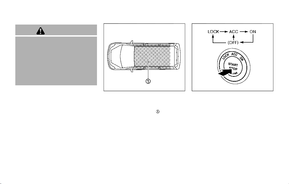
WARNING
Do not operate the push-button
ignition switch while driving the ve-
hicle except in an emergency. (The
engine will stop when the ignition
switch is pushed 3 consecutive times
or the ignition switch is pushed and
held for more than 2 seconds.) If the
engine stops while the vehicle is
being driven, this could lead to a
crash and serious injury.
Before operating the push-button igni-
tion switch, be sure to move the shift
lever to the P (Park) position.
SSD0436
OPERATING RANGE FOR ENGINE
START FUNCTION
The operating range for starting the
engine inside the vehicle
is shown in
the illustration.
. If the Intelligent Key is on the instru-
ment panel, cargo area, inside the
glove box or door pocket, or the
corner of interior compartment, it
may not be possible to start the
engine.
. If the Intelligent Key is near the door or
door glass outside the vehicle, it may
be possible to start the engine.
SSD1021
When the ignition switch is pushed with-
out depressing the brake pedal, the igni-
tion switch position will change as
follows:
. Push center once to change to ACC.
. Push center two times to change to
ON.
. Push center three times to change to
OFF. (No position illuminates.)
. Push center four times to return to
ACC.
. Open or close any door to return to
LOCK during the OFF position.
The ignition lock is designed so that the
ignition switch position cannot be
switched to LOCK until the shift lever is
Starting and driving 5-13
PUSH-BUTTON IGNITION SWITCH

5-14 Starting and driving
moved to the P (Park) position.
When the ignition switch cannot be
pushed toward the LOCK position, pro-
ceed as follows:
1. Move the shift lever into the P (Park)
position.
2. Push the ignition switch to the OFF
position. The ignition switch position
indicator will not illuminate.
3. Open the door. The ignition switch will
change to the LOCK position.
The shift lever can be moved from the P
(Park) position if the ignition switch is in
the ON position and the brake pedal is
depressed.
If the battery of the vehicle is dis-
charged, the push-button ignition
switch cannot be turned from the LOCK
position.
Some indicators and warnings for opera-
tion are displayed on the vehicle informa-
tion display between the speedometer
and tachometer. (See “Vehicle informa-
tion display” (P.2-20).)
PUSH-BUTTON IGNITION SWITCH
POSITIONS
LOCK (Normal parking position)
The ignition switch can only be locked in
this position.
The ignition switch will be unlocked when
it is pushed to the ACC position while
carrying the Intelligent Key.
ACC (Accessories)
This position activates electrical acces-
sories such as the radio, when the engine
is not running.
ACC has a battery saver feature that will
turn the ignition switch to the OFF posi-
tion after a period of time under the
following conditions:
. all doors are closed.
. shift lever is in P (Park).
. turn signal/hazard indicator lights are
not flashing.
The battery saver feature will be can-
celled if any of the following occur:
. any door is opened.
. shift lever is moved out of P (Park).
. ignition switch changes position.
ON (Normal operating position)
This position turns on the ignition system
and electrical accessories.
ON has a battery saver feature that will
turn the ignition switch to the OFF posi-
tion, if the vehicle is not running, after
some time under the following condi-
tions:
. all doors are closed.
. shift lever is in P (Park).
. turn signal/hazard indicator lights are
not flashing.
The battery saver feature will be can-
celled if any of the following occur:
. any door is opened.
. shift lever is moved out of P (Park).
. ignition switch changes position.
OFF
The engine can be turned off in the
position.
The ignition lock is designed so that the
ignition switch cannot be switched to the
LOCK position until the shift lever is
moved to the P (Park) position.
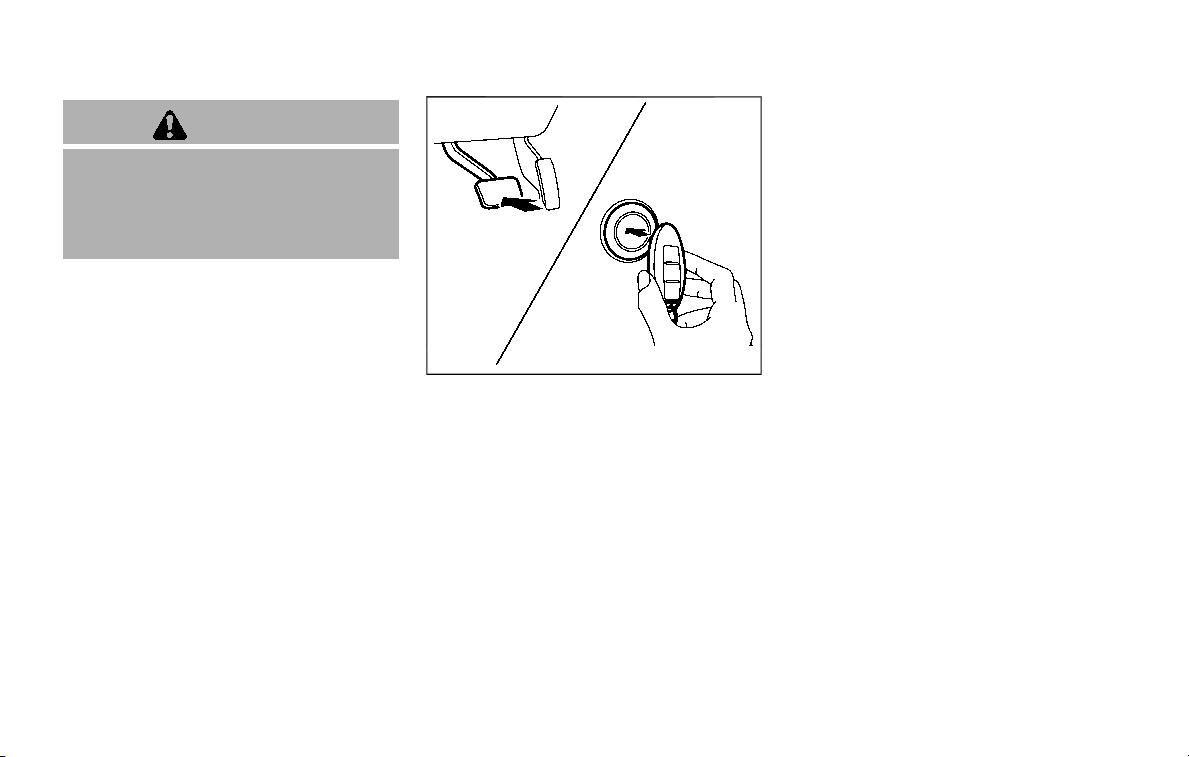
CAUTION
Do not leave the vehicle with the
push-button ignition switch in ACC or
ON positions when the engine is not
running for an extended period. This
can discharge the battery.
EMERGENCY ENGINE SHUT OFF
To shut off the engine in an emergency
situation while driving, perform the fol-
lowing procedure:
. Rapidly push the push-button ignition
switch 3 consecutive times in less
than 1.5 seconds, or
. Push and hold the push-button igni-
tion switch for more than 2 seconds.
JVS0404X
INTELLIGENT KEY BATTERY DIS-
CHARGE
If the battery of the Intelligent Key is
discharged, or environmental conditions
interfere with the Intelligent Key opera-
tion, start the engine according to the
following procedure:
1. Move the shift lever to the P (Park)
position.
2. Firmly apply the foot brake.
3. Touch the ignition switch with the
Intelligent Key as illustrated. (A chime
will sound.)
4. Push the ignition switch while depres-
sing the brake pedal within 10 sec-
onds after the chime sounds. The
engine will start.
After step 3 is performed, when the
ignition switch is pushed without depres-
sing the brake pedal, the ignition switch
position will change to ACC.
NOTE:
. When the ignition switch is pushed
to the ACC or ON position or the
engine is started by the above pro-
cedures, the Intelligent Key battery
discharge indicator appears on the
vehicle information display even if
the Intelligent Key is inside the
vehicle. This is not a malfunction.
To turn off the Intelligent Key bat-
tery discharge indicator, touch the
ignition switch with the Intelligent
Key again.
. If the Intelligent Key battery dis-
charge indicator appears, replace
the battery as soon as possible.
(See “Battery” (P.8-11).)
Starting and driving 5-15

5-16 Starting and driving
. Make sure the area around the vehicle
is clear.
. Check fluid levels such as engine oil,
coolant, brake fluid and window
washer fluid as frequently as possible,
or at least whenever you refuel.
. Check that all windows and lights are
clean.
. Visually inspect tires for their appear-
ance and condition. Also check tires
for proper inflation.
. Lock all doors.
. Position seat and adjust head re-
straints/headrests.
. Adjust inside and outside mirrors.
. Fasten seat belts and ask all passen-
gers to do likewise.
. Check the operation of warning lights
when the ignition switch is pushed to
the ON position. (See “Warning lights,
indicator lights and audible remin-
ders” (P.2-10).)
1. Apply the parking brake.
2. Move the shift lever to the P (Park) or N
(Neutral) position. (P is recommended.)
The starter is designed not to operate
unless the shift lever is in either of the
above positions.
3. Push the ignition switch to the ON
position. Firmly depress the brake
pedal and push the ignition switch to
start the engine.
To start the engine immediately, push
and release the ignition switch while
depressing the brake pedal with the
ignition switch in any position.
.
If the engine is very hard to start in
extremely cold weather or when
restarting, depress the accelerator
pedal a little (approximately 1/3 to
the floor) and while holding, crank
the engine. Release the accelerator
pedal when the engine starts.
.
If the engine is very hard to start
because it is flooded, depress the
accelerator pedal all the way to the
floor and hold it. Push the ignition
switch to the ON position to start
cranking the engine. After 5 or 6
seconds, stop cranking by pushing
the ignition switch to OFF. After
cranking the engine, release the
accelerator pedal. Crank the engine
with your foot off the accelerator
pedal by depressing the brake
pedal and pushing the push-button
ignition switch to start the engine.
If the engine starts, but fails to run,
repeat the above procedure.
CAUTION
Do not operate the starter for more
than 15 seconds at a time. If the
engine does not start, push the
ignition switch to OFF and wait 10
seconds before cranking again,
otherwise the starter could be da-
maged.
4. Warm-up
Allow the engine to idle for at least 30
seconds after starting. Do not race the
engine while warming it up. Drive at
moderate speed for a short distance
first, especially in cold weather. In cold
weather, keep the engine running for
a minimum of 2 - 3 minutes before
shutting it off. Starting and stopping
the engine over a short period of time
may make the vehicle more difficult to
start.
When racing the engine up to 4,000
rpm or more under the no load
condition, the engine will enter the
BEFORE STARTING THE ENGINE STARTING THE ENGINE

fuel cut mode.
5. To stop the engine, shift the shift lever
to the P (Park) position and push the
ignition switch to the OFF position.
In preparation for the next engine start,
the engine may have a slightly delayed
shutoff after placing the ignition switch in
the OFF position, depending on the driv-
ing conditions.
NOTE:
Care should be taken to avoid situations
that can lead to potential battery dis-
charge and potential no-start condi-
tions such as:
1. Installation or extended use of elec-
tronic accessories that consume
battery power when the engine is
not running (Phone chargers, GPS,
DVD players, etc.)
2. Vehicle is not driven regularly and/
or only driven short distances.
In these cases, the battery may need to
be charged to maintain battery health.
REMOTE ENGINE START (if so
equipped)
Vehicles started with the remote engine
start function require the ignition switch
to be placed in the ON position before the
shift lever can be moved from the P (Park)
position. To place the ignition switch in
the ON position, perform the following
steps:
1. Make sure that the Intelligent Key is
on you.
2. Firmly depress the brake pedal.
3. Push the ignition switch once to the
ON position.
For additional information about the
remote engine start function, see “Re-
mote engine start” (P.3-19).
ENGINE PROTECTION MODE
The engine has an engine protection
mode to reduce the chance of damage
if the coolant temperature becomes too
high (for example, when climbing steep
grades in high temperature with heavy
loads, such as when towing a trailer).
When the engine temperature reaches a
certain level:
. The engine coolant temperature
gauge will move toward the H posi-
tion.
. Engine power may be reduced.
. The air conditioning cooling function
may be automatically turned OFF for a
short time (the blower will continue to
operate).
Engine power and, under some condi-
tions, vehicle speed will decrease. Vehicle
speed can be controlled with the accel-
erator pedal, but the vehicle may not
accelerate at the desired speed. The
transmission will downshift or upshift as
it reaches prescribed shift points. You can
also shift manually.
As driving conditions change and engine
coolant temperature is reduced, vehicle
speed can be increased using the accel-
erator pedal, and air conditioning cooling
function will automatically be turned
back ON.
Starting and driving 5-17
DRIVING THE VEHICLE
5-18 Starting and driving
If:
1. The engine coolant temperature is not
reduced.
2. The air conditioning cooling function
does not turn back ON.
3. The engine oil pressure warning light
illuminates or engine coolant
temperature gauge does not return
to the normal range from the H
position, this may indicate a malfunc-
tion. Move the vehicle off the road to a
safe area and allow the engine to cool.
If after checking the oil and coolant,
the
remains on or engine coolant
temperature does not return to the
normal range, do not continue to
drive. It is recommended you contact
a NISSAN dealer.
The Malfunction Indicator Light (MIL)
may also come ON. You do not need to
have your vehicle towed, unless it re-
mains on, but have it inspected soon. It is
recommended you contact a NISSAN
dealer for this service. See “Warning lights,
indicator lights and audible reminders”
(P.2-10).
WARNING
Overheating can result in reduced
engine power and vehicle speed.
The reduced speed may be lower
than other traffic, which could in-
crease the chance of a collision. Be
especially careful when driving. If the
vehicle cannot maintain a safe driv-
ing speed, pull to the side of the road
in a safe area. Allow the engine to
cool and return to normal operation.
See “If your vehicle overheats” (P.6-
14).
CAUTION
Running the engine with the engine
oil pressure warning light on could
cause serious damage to the engine
almost immediately. Such damage is
not covered by warranty. Turn off the
engine as soon as it is safe to do so.
AUTOMATIC TRANSMISSION
7 speed automatic transmission
The automatic transmission in your vehi-
cle is electronically controlled by a trans-
mission control module to produce
maximum efficiency and smooth opera-
tion.
Shown on the following pages are the
recommended operating procedures for
this transmission. Follow these proce-
dures for maximum vehicle performance
and driving enjoyment.
Starting the vehicle
After starting the engine, fully depress the
foot brake pedal and push the shift lever
button before shifting the shift lever to
the R (Reverse), N (Neutral), D (Drive) or
Manual shift mode position. Be sure the
vehicle is fully stopped before attempting
to shift the shift lever.
This automatic transmission model is
designed so that the foot brake pedal
must be depressed before shifting from
P (Park) to any drive position while the
ignition switch position is ON.
The shift lever cannot be moved out of
the P (Park) position and into any of the
other gear positions if the ignition
switch is pushed to the LOCK, OFF or
ACC position.
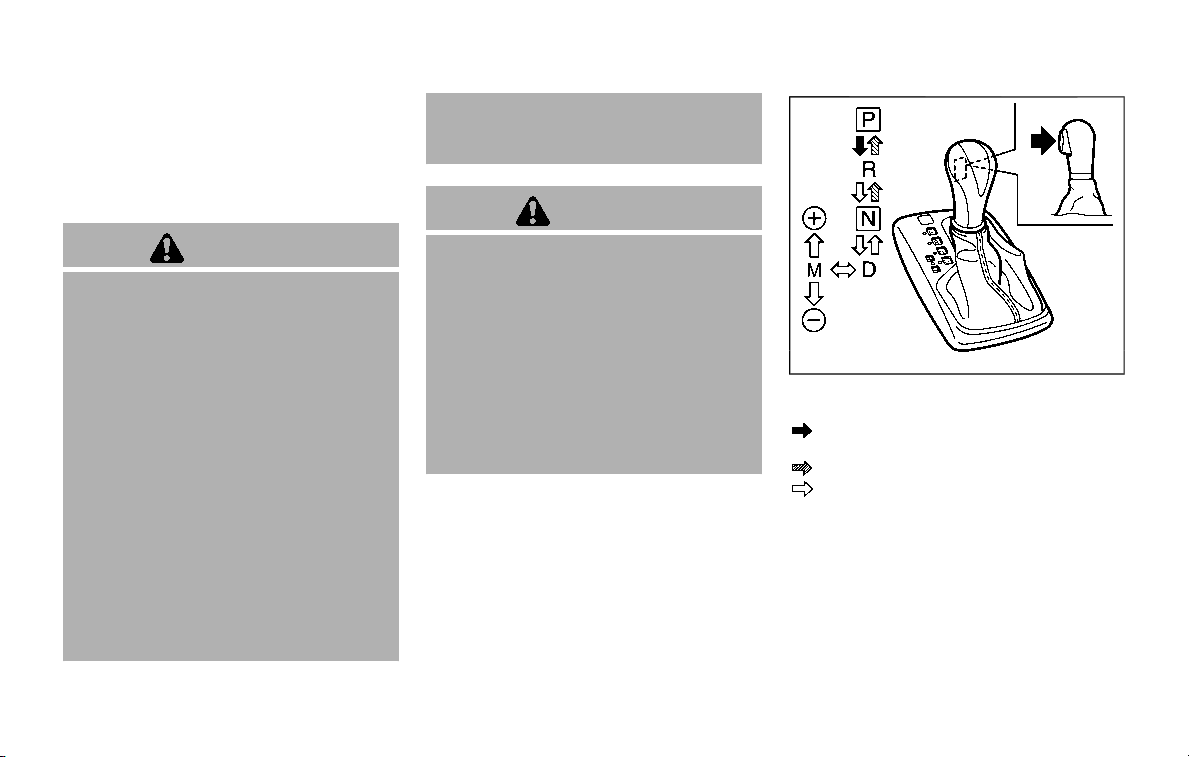
1. Keep the foot brake pedal depressed
and push the shift lever button to shift
into a driving gear.
2. Release the parking brake and foot
brake, then gradually start the vehicle
in motion.
WARNING
. Do not depress the accelerator
pedal while shifting from P (Park)
or N (Neutral) to R (Reverse), D
(Drive) or manual shift mode. Al-
ways depress the brake pedal
until shifting is completed. Failure
to do so could cause you to lose
control and have an accident.
. Cold engine idle speed is high, so
use caution when shifting into a
forward or reverse gear before
the engine has warmed up.
. Never shift to either the P (Park)
or R (Reverse) position while the
vehicle is moving forward and P
(Park), D (Drive) position or man-
ual shift mode while the vehicle is
moving rearward. This could
cause an accident or damage
the transmission.
. Do not downshift abruptly on
slippery roads. This may cause a
loss of control.
CAUTION
. Except in an emergency, do not
shift to the N (Neutral) position
while driving. Coasting with the
transmission in the N (Neutral)
position may cause serious da-
mage to the transmission.
. To avoid possible damage to your
vehicle; when stopping the vehi-
cle on an uphill grade, do not hold
the vehicle by depressing the
accelerator pedal. The foot brake
should be used for this purpose.
SSD0945
Shift lever
To move the shift lever,
: Push the button while depressing the
brake pedal,
: Push the button,
: Just move the shift lever.
Shifting
The shift lever position indicator light
(next to the shift lever) will be illuminated
for approximately 30 minutes after the
ignition switch is turned off. The indicator
light may also illuminate when the vehicle
receives radio waves. This is not a mal-
function.
After starting the engine, fully depress the
Starting and driving 5-19

5-20 Starting and driving
brake pedal and shift the shift lever from
P (Park) to R (Reverse), N (Neutral), D
(Drive) or Manual shift mode position.
Push the button to shift into P (Park) or R
(Reverse). All other positions can be
selected without pushing the button.
WARNING
Apply the parking brake if the shift
lever is in any position while the
engine is not running. Failure to do
so could cause the vehicle to move
unexpectedly or roll away and result
in serious personal injury or property
damage.
CAUTION
Make sure the vehicle is completely
stopped and the transmission is in
the P (Park) position.
P (Park) position:
Use this position when the vehicle is
parked or when starting the engine. Make
sure the vehicle is completely stopped.
The brake pedal must be depressed and
the shift lever button pushed in to move
the shift lever from the N (Neutral)
position or any drive position to the P
(Park) position. Apply the parking brake.
When parking on a hill, apply the parking
brake first, then move the shift lever to
the P (Park) position.
CAUTION
Use this position only when the
vehicle is completely stopped.
R (Reverse):
Use this position to back up. Always be
sure the vehicle is completely stopped
before selecting the R (Reverse) position.
The brake pedal must be depressed and
the shift lever button pushed in to move
the shift lever from the P (Park) posi-
tion, the N (Neutral) position or any
drive position to the R (Reverse) posi-
tion.
N (Neutral):
Neither forward nor reverse gear is en-
gaged. The engine can be started in this
position. You may shift to the N (Neutral)
position and restart a stalled engine while
the vehicle is moving.
D (Drive):
Use this position for all normal forward
driving.
Manual shift mode
When the shift lever is in the manual shift
gate, the transmission is ready for the
manual shift mode. Shift ranges can be
selected manually by moving the shift
lever up or down.
When shifting up, move the shift lever to
the + (up) side. The transmission shifts to
the higher range.
When shifting down, move the shift lever
to the − (down) side. The transmission
shifts to the lower range.
When canceling the manual shift mode,
return the shift lever to the D (Drive)
position. The transmission returns to the
normal driving mode.
In the manual shift mode, the shift range
is displayed on the position indicator in
the meter.

Shift ranges up or down one by one as
follows:
M
1
?
/
M
2
?
/
M
3
?
/
M
4
?
/
M
5
?
/
M
6
?
/
M
7
M
7 (7th):
Use this position for all normal forward
driving at highway speeds.
M
6 (6th) and
M
5 (5th):
Use these positions when driving up long
slopes, or for engine braking when driving
down long slopes.
M
4 (4th),
M
3 (3rd) and
M
2 (2nd):
Use these positions for hill climbing or
engine braking on downhill grades.
M
1 (1st):
Use this position when climbing steep
hills slowly or driving slowly through deep
snow, or for maximum engine braking on
steep downhill grades.
. Remember not to drive at high speeds
for extended periods of time in lower
than 7th gear. This reduces fuel econ-
omy.
. Moving the shift lever rapidly to the
same side twice will shift the ranges in
succession.
. In the manual shift mode, the trans-
mission may not shift to the se-
lected gear or may automatically
shift to the other gear. This helps
maintain driving performance and
reduces the chance of vehicle da-
mage or loss of control.
. When the transmission does not
shift to the selected gear, the Auto-
matic Transmission (AT) position in-
dicator light (in the vehicle
information display) will blink and
the buzzer will sound.
. In the manual shift mode, the trans-
mission automatically shifts down
to 1st gear before the vehicle comes
to a stop. When accelerating again, it
is necessary to shift up to the
desired range.
Accelerator downshift — In D (Drive)
position —
For passing or hill climbing, fully depress
the accelerator pedal to the floor. This
shifts the transmission down into the
lower gear, depending on the vehicle
speed.
Fail-safe
When the fail-safe operation occurs, note
that the transmission will be locked in any
of the forward gears according to the
condition.
If the vehicle is driven under extreme
conditions, such as excessive wheel
spinning and subsequent hard braking,
the fail-safe system may be activated.
This will occur even if all electrical
circuits are functioning properly. In this
case, push the switch to the OFF posi-
tion and wait for 3 seconds. Then push
the ignition switch back to the ON
position. The vehicle should return to
its normal operating condition. If it does
not return to its normal operating con-
dition, have the transmission checked
and repaired, if necessary. It is recom-
mended you visit a NISSAN dealer for
this service.
Starting and driving 5-21
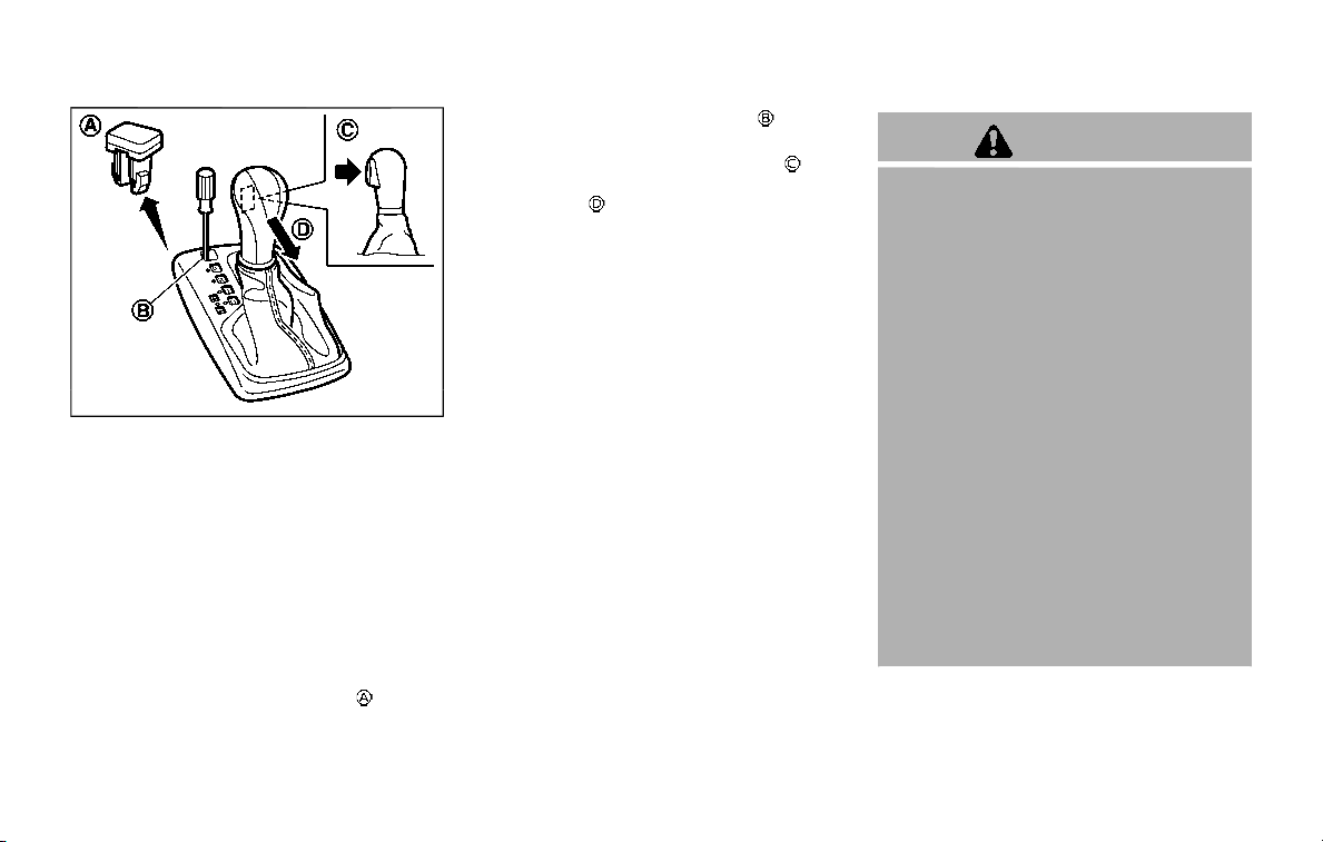
5-22 Starting and driving
SSD0946
Shift lock release
If the battery charge is low or discharged,
the shift lever may not be moved from the
P (Park) position even with the brake
pedal depressed and the shift lever but-
ton pushed.
To move the shift lever, perform the
following procedure:
1. Place the ignition switch in the OFF or
LOCK position.
2. Apply the parking brake.
3. Remove the shift lock cover
using a
suitable tool.
4. Push down the shift lock
as illu-
strated.
5. Push the shift lever button
and
move the shift lever to N (Neutral)
position
while holding down the
shift lock.
The vehicle may be moved to the desired
location.
If the lever cannot be moved out of P
(Park), have the automatic transmission
system checked as soon as possible. It is
recommended you visit a NISSAN dealer
for this service.
WARNING
. Be sure the parking brake is fully
released before driving. Failure to
do so can cause brake failure and
lead to an accident.
. Do not release the parking brake
from outside the vehicle.
. Do not use the gear shift in place
of the parking brake. When park-
ing, be sure the parking brake is
fully engaged.
. To help avoid risk of injury or
death through unintended opera-
tion of the vehicle and/or its
systems, do not leave children,
people who require the assis-
tance of others or pets unat-
tended in your vehicle.
Additionally, the temperature in-
side a closed vehicle on a warm
day can quickly become high
enough to cause a significant risk
of injury or death to people and
pets.
PARKING BRAKE
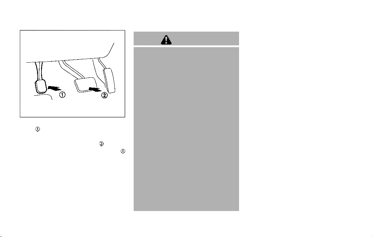
SPA2331
To apply: Fully depress the parking brake
pedal
.
To release:
1. Firmly apply the foot brake
.
2. Depress the parking brake pedal
and the parking brake will be released.
3. Before driving, be sure the brake
warning light goes out.
WARNING
Failure to follow the warnings and
instructions for proper use of the
LDW and I-LI systems could result in
serious personal injury or death.
. The LDW and I-LI systems will not
prevent loss of control. It is the
driver’s responsibility to stay
alert, drive safely, keep the vehi-
cle in the traveling lane, and be in
control of the vehicle at all times.
. The I-LI system may activate if
you change lanes without first
activating your turn signal or, for
example, if a construction zone
directs traffic to cross an existing
lane marker. If this occurs, you
may need to apply corrective
steering to complete your lane
change.
. Because the I-LI system may not
activate under the road, weather,
and lane marker conditions de-
scribed in this section, it may not
activate every time your vehicle
begins to leave its lane and you
will need to apply corrective
steering.
. Lane Departure Warning (LDW) system
— warns the driver with a warning
light and chime that the vehicle is
beginning to leave the driving lane.
. Intelligent Lane Intervention (I-LI) sys-
tem
— warns the driver with a warning
light and chime, and helps assist
the driver to return the vehicle to
the center of the traveling lane by
applying the brakes to the left or
right wheels individually (for a short
period of time).
Starting and driving 5-23
LANE DEPARTURE WARNING (LDW)/
INTELLIGENT LANE INTERVENTION
(I-LI) (if so equipped)
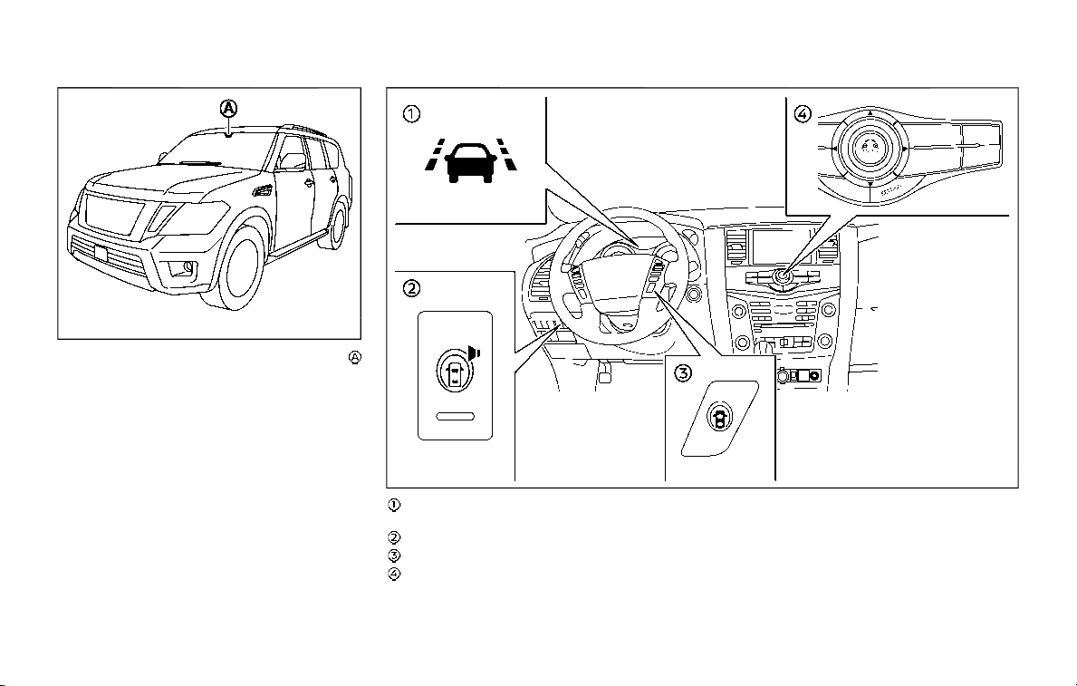
5-24 Starting and driving
JVS0907X
The LDW and I-LI systems use a camera
installed behind the windshield to moni-
tor the lane markers of your traveling
lane.
JVS1094X
I-LI ON indicator light/LDW indicator light
(on the instrument panel)
Warning systems switch
Dynamic driver assistance switch
Center multi-function control panel
LDW SYSTEM OPERATION
The LDW system operates above approxi-
mately 45 MPH (70 km/h) and when the
lane markings are clear.
If the vehicle approaches either the left or
right side of the traveling lane, the LDW
indicator light (orange) on the instrument
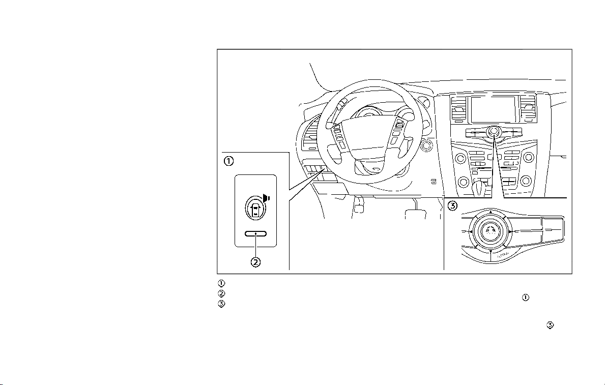
panel will flash and a warning chime will
sound.
NOTE:
The LDW system is not designed to
warn when you operate the lane
change signal and change traveling
lanes in the direction of the signal.
(The LDW system will become operable
again approximately 2 seconds after
the lane change signal is turned off.)
JVS1130X
Warning systems switch
Warning systems ON indicator light
Center multi-function control panel
TURNING THE LDW SYSTEM ON/OFF
The warning systems switch is used to
turn on and off the LDW system when it is
activated on the center display using the
center multi-function control panel
. See
“How to enable/disable the LDW system”
(P.5-26). When the warning systems
Starting and driving 5-25
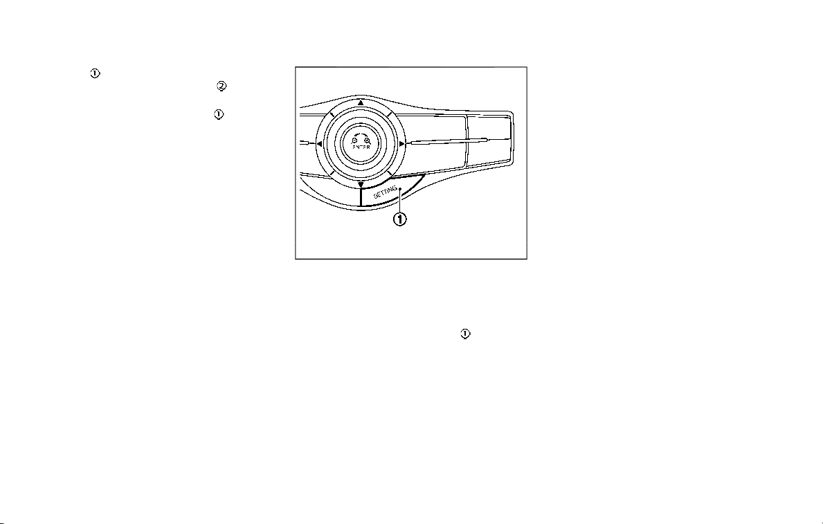
5-26 Starting and driving
switch is turned off, the warning
systems ON indicator light
on the
switch is off.
The warning systems switch
will turn
on and off the LDW and BSW (if so
equipped) systems at the same time.
JVS1043X
HOW TO ENABLE/DISABLE THE LDW
SYSTEM
Perform the following steps to enable or
disable the LDW system.
1. Push the SETTING button
.
2. Touch [Driver Assistance].
3. Touch [Lane Assist].
4. Touch [Lane Departure Warning] to
turn the system ON/OFF.
I-LI SYSTEM OPERATION
The I-LI system operates above approxi-
mately 45 MPH (70 km/h) and when the
lane markings are clear.
If the vehicle approaches either the left or
right side of the traveling lane, the LDW
indicator light (orange) on the instrument
panel will flash and a warning chime will
sound. Then, the I-LI system will auto-
matically apply the brakes for a short
period of time to help assist the driver to
return the vehicle to the center of the
traveling lane.
NOTE:
. The I-LI system is not designed to
work when you operate the lane
change signal and change traveling
lanes in the direction of the signal.
(The I-LI system will become oper-
able again approximately 2 seconds
after the lane change signal is
turned off.)
. The I-LI braking assist will not oper-
ate or will stop operating and only a
warning chime will sound under the
following conditions.
— When the brake pedal is de-
pressed.
— When the steering wheel is turned
as far as necessary for the vehicle
to change lanes.
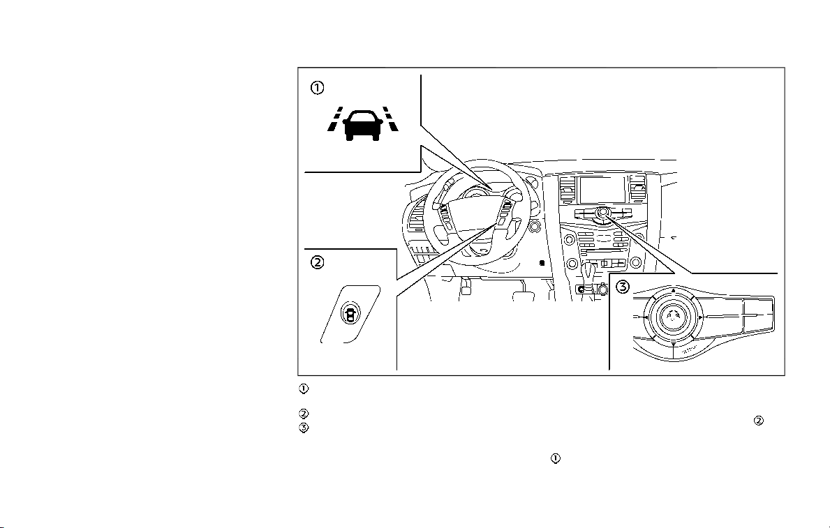
— When the accelerator pedal is
depressed while brake control
assist is provided.
— When the ICC, I-DC, I-BSI, BSW, I-
FCW or AEB warnings sound.
— When the hazard warning flashers
are operated.
— When driving on a curve at a high
speed.
. While the I-LI system is operating,
you may hear a sound of brake
operation. This is normal and indi-
cates that the I-LI system is operat-
ing properly.
JVS1095X
I-LI ON indicator light (green) (on the
instrument panel)
Dynamic driver assistance switch
Center multi-function control panel
TURNING THE I-LI SYSTEM ON/OFF
To turn on the I-LI system, push the
dynamic driver assistance switch
on
the steering wheel after starting the
engine. The I-LI ON indicator light (green)
on the instrument panel will illuminate.
Push the dynamic driver assistance
Starting and driving 5-27
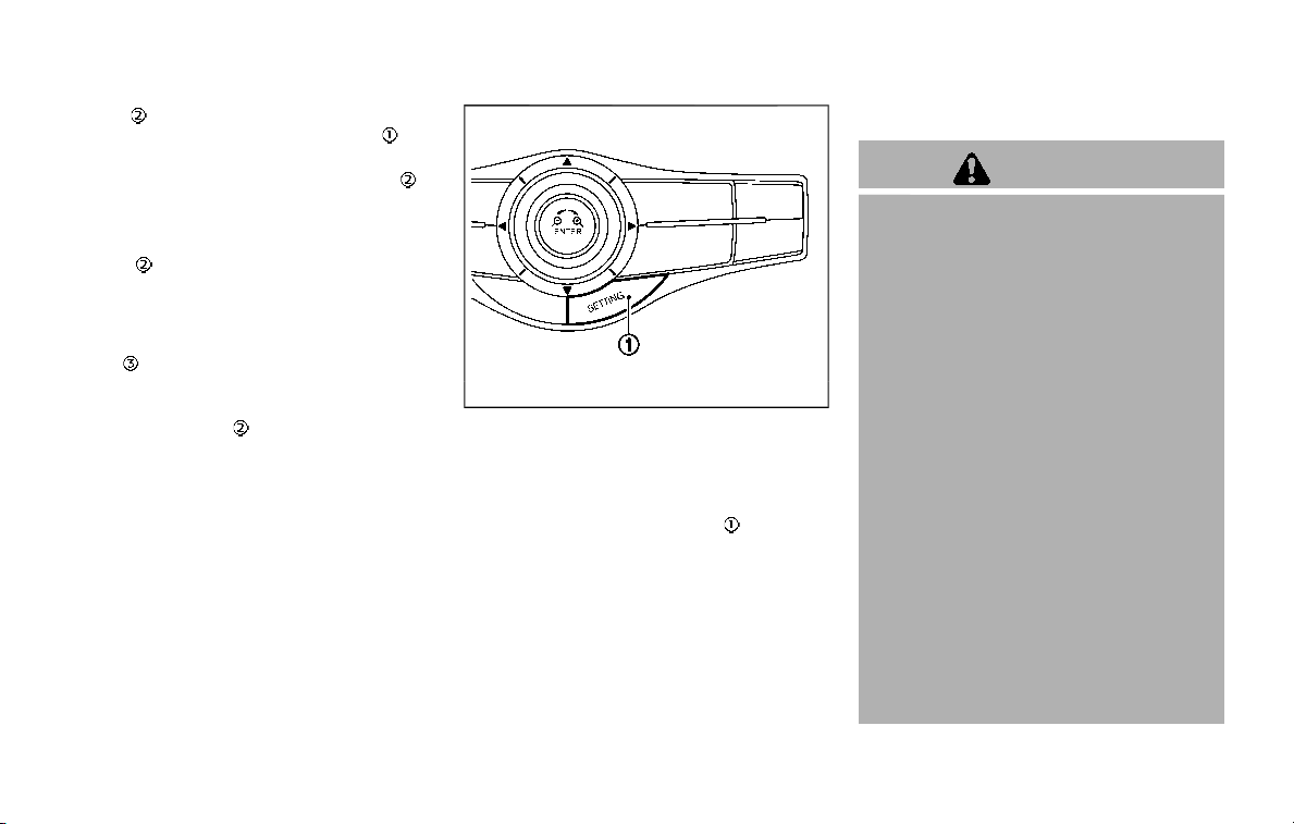
5-28 Starting and driving
switch again to turn off the I-LI system.
The I-LI ON indicator light (green)
will
turn off.
The dynamic driver assistance switch
is
used for the I-LI, I-BSI (if so equipped) and
I-DC systems.
When the dynamic driver assistance
switch
is pushed, the I-BSI and I-DC
systems will also turn on or off simulta-
neously. The I-LI system can be individu-
ally set to on or off on the center display
using the center multi-function control
panel
.
If the system is set to off, the system will
not turn on even if the dynamic driver
assistance switch
is pushed to on. To
set the system to on or off on the center
display, see “How to enable/disable the I-
LI system” (P.5-28).
JVS1043X
HOW TO ENABLE/DISABLE THE I-LI
SYSTEM
Perform the following steps to enable the
I-LI system.
1. Push the SETTING button
.
2. Touch [Driver Assistance].
3. Touch [Lane Assist].
4. Touch [Lane Departure Prevention] to
turn the system ON/OFF.
LDW/I-LI SYSTEM LIMITATIONS
WARNING
Listed below are the system limita-
tions for the LDW and I-LI systems.
Failure to operate the vehicle in
accordance with these system lim-
itations could result in serious injury
or death.
. The system will not operate at
speeds below 45 MPH (70 km/h)
or if it cannot detect lane mar-
kers.
. The I-LI system is primarily in-
tended for use on well-developed
freeways or highways. It may not
detect the lane markers in certain
roads, weather or driving condi-
tions.
. Do not use the I-LI system under
the following conditions as it may
not function properly:
— During bad weather (rain, fog,
snow, etc.).
— When driving on slippery
roads, such as on ice or snow,
etc.

— When driving on winding or
uneven roads.
— When there is a lane closure
due to road repairs.
— When driving in a makeshift or
temporary lane.
— When driving on roads where
the lane width is too narrow.
— When driving without normal
tire conditions (for example,
tire wear, low tire pressure,
installation of spare tire, tire
chains, non-standard wheels).
— When the vehicle is equipped
with non-original brake parts
or suspension parts.
— When towing a trailer or other
vehicle.
. The camera may not detect lane
markers in the following situa-
tions and the LDW and I-LI sys-
tems may not operate properly.
— On roads where there are
multiple parallel lane markers,
lane markers that are faded or
not painted clearly, yellow
painted lane markers, non-
standard lane markers, or
lane markers covered with
water, dirt, snow, etc.
— On roads where the discontin-
ued lane markers are still
detectable.
— On roads where there are
sharp curves.
— On roads where there are
sharply contrasting objects,
such as shadows, snow,
water, wheel ruts, seams or
lines remaining after road re-
pairs. (The LDW and I-LI sys-
tems could detect these items
as lane markers.)
— On roads where the traveling
lane merges or separates.
— When the vehicle’s traveling
direction does not align with
the lane marker.
— When traveling close to the
vehicle in front of you, which
obstructs the lane camera
unit detection range.
— When rain, snow or dirt ad-
heres to the windshield in
front of the lane camera unit.
— When the headlights are not
bright due to dirt on the lens
or if the aiming is not adjusted
properly.
— When strong light enters the
lane camera unit. (For exam-
ple, the light directly shines on
the front of the vehicle at
sunrise or sunset.)
— When a sudden change in
brightness occurs. (For exam-
ple, when the vehicle enters or
exits a tunnel or under a
bridge.)
. Excessive noise will interfere with
the warning chime sound, and
the chime may not be heard.
Starting and driving 5-29
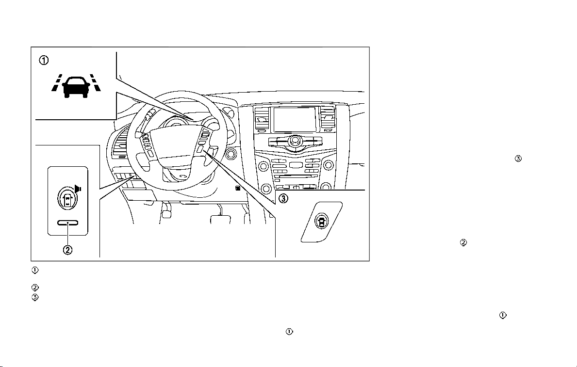
5-30 Starting and driving
JVS0882X
I-LI ON indicator light (green) (on the
instrument panel)
Warning systems ON indicator light
Dynamic driver assistance switch
SYSTEM TEMPORARILY UNAVAIL-
ABLE
Condition A:
Under the following conditions, a beep
will sound and the I-LI system will be
canceled automatically. The I-LI ON in-
dicator light (green)
will blink, and the I-
LI system cannot be activated:
. When the VDC system (except TCS
function) or ABS operates.
. When the VDC system is turned off.
. When the SNOW mode switch is
turned on.
. When the 4WD shift switch is in the 4H
or 4L position (for 4WD models).
Action to take:
When the above conditions no longer
exist, turn off the I-LI system. Push the
dynamic driver assistance switch
again
to turn the I-LI system back on.
Condition B:
LDW system: If the vehicle is parked in
direct sunlight under high temperature
conditions (over approximately 104°F
(40°C)) and then the LDW system is turned
on, the LDW system may be deactivated
automatically, and the warning systems
ON indicator light
on the switch will
blink.
I-LI system: If the vehicle is parked in
direct sunlight under high temperature
conditions (over approximately 104°F
(40°C)) and then the I-LI system is turned
on, the I-LI system will be turned off
automatically, a beep will sound and the
I-LI ON indicator light (green)
will blink.
The LDW and I-LI systems are not avail-
able until the conditions no longer exist.
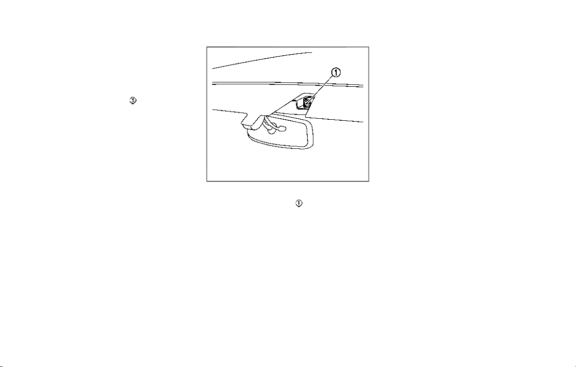
Action to take:
When the above conditions no longer
exist, the LDW system will resume auto-
matically.
For the I-LI system, push the dynamic
driver assistance switch
again to turn
the I-LI system back on.
SYSTEM MALFUNCTION
LDW system: When the LDW system
malfunctions, it will cancel automatically,
and the LDW indicator light (orange) will
illuminate.
I-LI system: When the I-LI system mal-
functions, it will be turned off automati-
cally, a beep will sound, and the LDW
indicator light (orange) will illuminate.
Action to take:
Stop the vehicle in a safe location, place
the vehicle in the P (Park) position, turn
the engine off and restart the engine. If
the LDW indicator light (orange) con-
tinues to illuminate, have the system
checked. It is recommended you visit a
NISSAN dealer for this service.
SSD0453
SYSTEM MAINTENANCE
The lane camera unit for the LDW/I-LI
systems is located above the inside
mirror.
To keep the proper operation of the LDW/
I-LI systems and prevent a system mal-
function, be sure to observe the following:
. Always keep the windshield clean.
. Do not attach a sticker (including
transparent material) or install an
accessory near the camera unit.
. Do not place reflective materials, such
as white paper or a mirror, on the
instrument panel. The reflection of
sunlight may adversely affect the
camera unit’s capability of detecting
the lane markers.
. Do not strike or damage the areas
around the camera unit. Do not touch
the camera lens or remove the screw
located on the camera unit. It is
recommended you contact a NISSAN
dealer if the camera unit is damaged
due to an accident.
Starting and driving 5-31
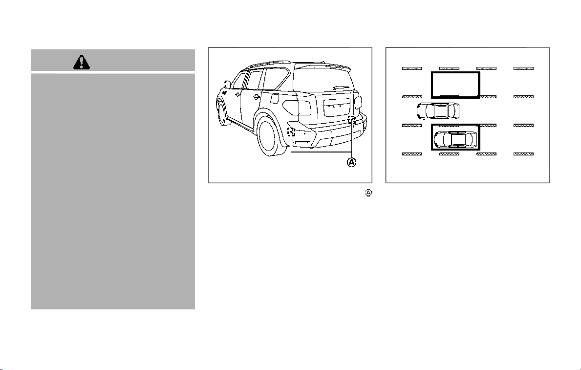
5-32 Starting and driving
WARNING
Failure to follow the warnings and
instructions for proper use of the
BSW system could result in serious
injury or death.
. The BSW system is not a replace-
ment for proper driving proce-
dure and is not designed to
prevent contact with vehicles or
objects. When changing lanes, al-
ways use the side and rear mir-
rors and turn and look in the
direction your vehicle will move
to ensure it is safe to change
lanes. Never rely solely on the
BSW system.
. There is a limitation to the detec-
tion capability of the radar. Not
every moving object or vehicle
will be detected. Using the BSW
system under some road, ground,
lane marker, traffic or weather
conditions could lead to improper
system operation. Always rely on
your own operation to avoid ac-
cidents.
The BSW system helps alert the driver of
other vehicles in adjacent lanes when
changing lanes.
JVS0908X
The BSW system uses radar sensors
installed near the rear bumper to detect
other vehicles in an adjacent lane.
SSD1030
Detection zone
The radar sensors can detect vehicles on
either side of your vehicle within the
detection zone shown as illustrated. This
detection zone starts from the outside
mirror of your vehicle and extends ap-
proximately 10 ft (3.0 m) behind the rear
bumper, and approximately 10 ft (3.0 m)
sideways.
BLIND SPOT WARNING (BSW) (if so
equipped)

JVS1096X
Side indicator light
BSW system warning light
Warning systems switch
Center multi-function control panel
BSW SYSTEM OPERATION
The BSW system operates above approxi-
mately 20 MPH (32 km/h).
If the radar sensors detect a vehicle in the
detection zone, the side indicator light
illuminates.
If the turn signal is then activated, the
system chimes (twice) and the side in-
dicator light flashes. The side indicator
light continues to flash until the detected
vehicle leaves the detection zone.
NOTE:
. The side indicator light illuminates
for a few seconds when the ignition
switch is placed in the ON position.
. The brightness of the side indicator
light is adjusted automatically de-
pending on the brightness of the
ambient light.
. If a vehicle comes into the detection
zone after the driver activates the
turn signal, then only the side in-
dicator light flashes and no chime
sounds. For additional information,
refer to “BSW driving situations”
(P.5-36).
Starting and driving 5-33

5-34 Starting and driving
JVS1130X
Warning systems switch
Warning systems ON indicator light
Center multi-function control panel
TURNING THE BSW SYSTEM ON/OFF
The warning systems switch is used to
turn on and off the BSW system when it is
activated on the center display using the
center multi-function control panel
. See
“How to enable/disable the BSW system”
(P.5-34). When the warning systems
switch
is turned off, the warning
systems ON indicator light
on the
switch is off.
The warning systems switch
will turn
on and off the LDW and BSW systems at
the same time.
HOW TO ENABLE/DISABLE THE BSW
SYSTEM
The BSW system can be turned off
permanently using the center display.
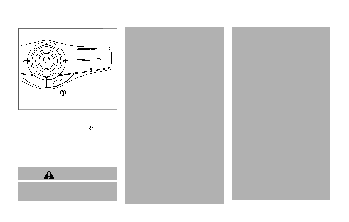
JVS1043X
Perform the following steps to enable or
disable the BSW system.
1. Push the SETTING button
.
2. Touch [Driver Assistance].
3. Touch [Blind Spot Assist].
4. Touch [Blind Spot Warning] to turn the
system ON/OFF.
BSW SYSTEM LIMITATIONS
WARNING
Listed below are the system limita-
tions for the BSW system. Failure to
operate the vehicle in accordance
with these system limitations could
result in serious injury or death.
. The BSW system cannot detect all
vehicles under all conditions.
. The radar sensors may not be
able to detect and activate BSW
when certain objects are present
such as:
— Pedestrians, bicycles, animals.
— Vehicles such as motorcycles,
low height vehicles, or high
ground clearance vehicles.
— Oncoming vehicles.
— Vehicles remaining in the de-
tection zone when you accel-
erate from a stop.
— A vehicle merging into an
adjacent lane at a speed ap-
proximately the same as your
vehicle.
— A vehicle approaching rapidly
from behind.
— A vehicle which your vehicle
overtakes rapidly.
— A vehicle that passes through
the detection zone quickly.
. The radar sensor’s detection zone
is designed based on a standard
lane width. When driving in a
wider lane, the radar sensors
may not detect vehicles in an
adjacent lane. When driving in a
narrow lane, the radar sensors
may detect vehicles driving two
lanes away.
. The radar sensors are designed
to ignore most stationary objects,
however objects such as guard-
rails, walls, foliage and parked
vehicles may occasionally be de-
tected. This is a normal operation
condition.
. The following conditions may re-
duce the ability of the radar to
detect other vehicles:
— Severe weather
— Road spray
— Ice/frost/snow build-up on
the vehicle
— Dirt build-up on the vehicle
. Do not attach stickers (including
transparent material), install ac-
cessories or apply additional
paint near the radar sensors.
These conditions may reduce the
ability of the radar to detect other
vehicles.
Starting and driving 5-35
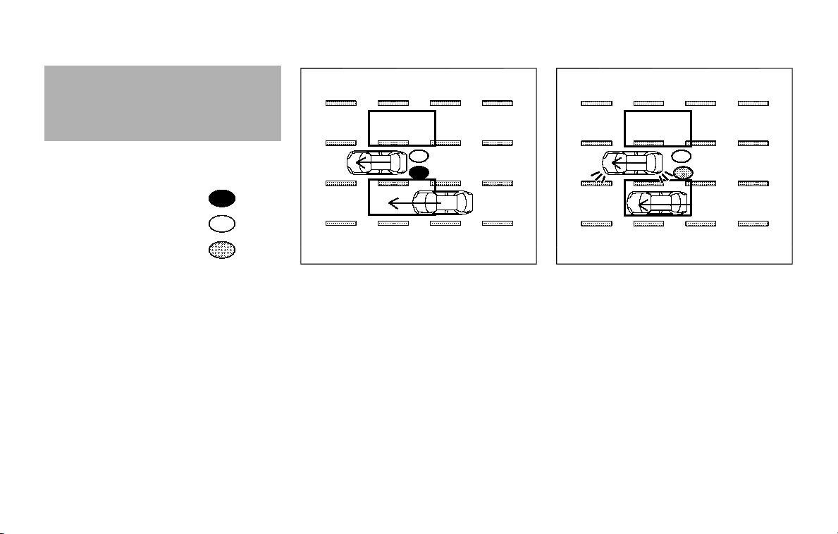
5-36 Starting and driving
. Excessive noise (for example,
audio system volume, open vehi-
cle window) will interfere with the
chime sound, and it may not be
heard.
BSW DRIVING SITUATIONS
Indicator on
Indicator off
Indicator flashing
JVS0737X
Illustration 1 – Approaching from behind
Another vehicle approaching from
behind
Illustration 1: The side indicator light
illuminates if a vehicle enters the detec-
tion zone from behind in an adjacent lane.
JVS0738X
Illustration 2 – Approaching from behind
Illustration 2: If the driver activates the
turn signal, then the system chimes
(twice) and the side indicator light flashes.
NOTE:
. The radar sensors may not detect
vehicles which are approaching ra-
pidly from behind.
. If the driver activates the turn signal
before a vehicle enters the detection
zone, the side indicator light will
flash but no chime will sound when
the other vehicle is detected.
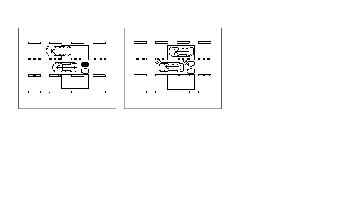
JVS0739X
Illustration 3 – Overtaking another vehicle
Overtaking another vehicle
Illustration 3: The side indicator light
illuminates if you overtake a vehicle and
that vehicle stays in the detection zone
for approximately 3 seconds.
The radar sensors may not detect slower
moving vehicles if they are passed
quickly.
JVS0740X
Illustration 4 – Overtaking another vehicle
Illustration 4: If the driver activates the
turn signal while another vehicle is in the
detection zone, then the system chimes
(twice) and the side indicator light flashes.
NOTE:
. When overtaking several vehicles in
a row, the vehicles after the first
vehicle may not be detected if they
are traveling close together.
. The radar sensors may not detect
slower moving vehicles if they are
passed quickly.
. If the driver activates the turn signal
before a vehicle enters the detection
zone, the side indicator light will
flash but no chime will sound when
the other vehicle is detected.
Starting and driving 5-37
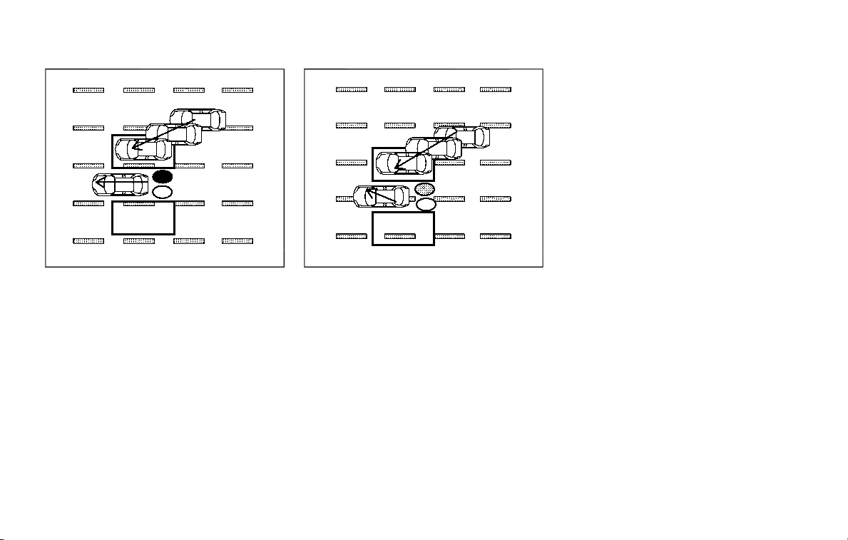
5-38 Starting and driving
JVS0741X
Illustration 5 – Entering from the side
Entering from the side
Illustration 5: The side indicator light
illuminates if a vehicle enters the detec-
tion zone from either side.
JVS0742X
Illustration 6 – Entering from the side
Illustration 6: If the driver activates the
turn signal, then the system chimes
(twice) and the side indicator light flashes.
NOTE:
. The radar sensors may not detect a
vehicle which is traveling at about
the same speed as your vehicle
when it enters the detection zone.
. If the driver activates the turn signal
before a vehicle enters the detection
zone, the side indicator light will
flash but no chime will sound when
the other vehicle is detected.
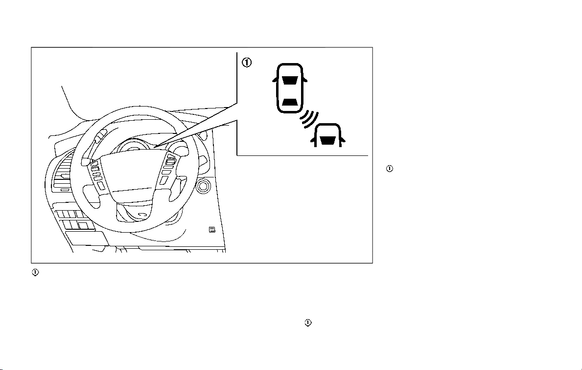
JVS0687X
BSW system warning light (orange)
SYSTEM TEMPORARILY UNAVAIL-
ABLE
When radar blockage is detected, the
system will be turned off automatically,
a beep will sound and the BSW system
warning light (orange)
will blink. The
system is not available until the condi-
tions no longer exist.
The radar sensors may be blocked by
temporary ambient conditions such as
splashing water, mist or fog. The blocked
condition may also be caused by objects
such as ice, frost or dirt obstructing the
radar sensors.
Action to take:
When the above conditions no longer
exist, the system will resume automati-
cally.
If the BSW system warning light (orange)
continues to blink, have the system
checked. It is recommended you visit a
NISSAN dealer for this service.
SYSTEM MALFUNCTION
When the system malfunctions, it will be
turned off automatically, a beep will
sound and the BSW system warning light
(orange) will illuminate.
Action to take:
Stop the vehicle in a safe location, place
the vehicle in the P (Park) position, turn
the engine off and restart the engine.
If the BSW system warning light continues
to illuminate, have the system checked. It
is recommended you visit a NISSAN dealer
for this service.
Starting and driving 5-39
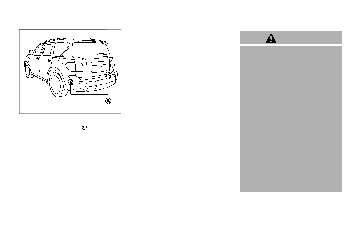
5-40 Starting and driving
JVS0908X
SYSTEM MAINTENANCE
The two radar sensors for the BSW
system are located near the rear bumper.
Always keep the area near the radar
sensors clean.
The radar sensors may be blocked by
temporary ambient conditions such as
splashing water, mist or fog.
The blocked condition may also be
caused by objects such as ice, frost or
dirt obstructing the radar sensors.
Check for and remove objects obstruct-
ing the area around the radar sensors.
Do not attach stickers (including trans-
parent material), install accessories or
apply additional paint near the radar
sensors.
Do not strike or damage the area around
the radar sensors.
It is recommended you visit a NISSAN
dealer if the area around the radar
sensors is damaged due to a collision.
Radio frequency statement
This device complies with part 15 of the
FCC Rules and RSS-310 of Industry Cana-
da.
Operation is subject to the following two
conditions:
1. This device may not cause harmful
interference.
2. This device must accept any interfer-
ence received, including interference
that may cause undesired operation.
Frequency of operation: 24.05GHz —
24.25GHz
Field Strength: Not greater than 2.5V/m
peak (0.25V/m average) at a distance of 3
m
The manufacturer is not responsible for
any radio or TV interference caused by
unauthorized modifications to this equip-
ment. Such modifications could void the
user’s authority to operate the equip-
ment.
WARNING
Failure to follow the warnings and
instructions for proper use of the I-
BSI system could result in serious
injury or death.
. The I-BSI system is not a replace-
ment for proper driving proce-
dures and is not designed to
prevent contact with vehicles or
objects. When changing lanes, al-
ways use the side and rear mir-
rors and turn and look in the
direction your vehicle will move
to ensure it is safe to change
lanes. Never rely solely on the I-
BSI system.
. There is a limitation to the detec-
tion capability of the radar. Not
every moving object or vehicle
will be detected. Using the I-BSI
system under some road, ground,
lane marker, traffic or weather
conditions could lead to improper
system operation. Always rely on
your own operation to avoid ac-
cidents.
The I-BSI system helps alert the driver of
other vehicles in adjacent lanes when
changing lanes and helps assist the driver
INTELLIGENT BLIND SPOT
INTERVENTION (I-BSI) (if so equipped)
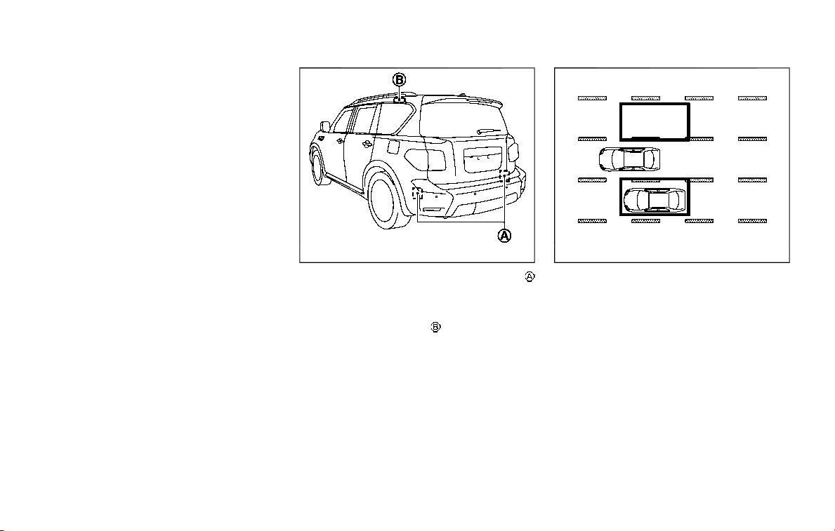
to return the vehicle to the center of the
traveling lane.
JVS0910X
The I-BSI system uses radar sensors
installed near the rear bumper to detect
other vehicles in an adjacent lane. In
addition to the radar sensors, the I-BSI
system uses a camera
installed behind
the windshield to monitor the lane mar-
kers of your traveling lane.
SSD1030
Detection zone
The radar sensors can detect vehicles on
either side of your vehicle within the
detection zone shown as illustrated.
This detection zone starts from the out-
side mirror of your vehicle and extends
approximately 10 ft (3.0 m) behind the
rear bumper, and approximately 10 ft (3.0
m) sideways.
Starting and driving 5-41

5-42 Starting and driving
JVS1097X
Side indicator light
I-BSI ON indicator light (green)/I-BSI sys-
tem warning light (orange)
Dynamic driver assistance switch
Center multi-function control panel
I-BSI SYSTEM OPERATION
The I-BSI system operates above approxi-
mately 37 MPH (60 km/h).
If the radar sensors detect a vehicle in the
detection zone, the side indicator light
illuminates.
If the turn signal is then activated, the
system chimes (twice) and the side in-
dicator light flashes. The side indicator
light continues to flash until the detected
vehicle leaves the detection zone.
If the I-BSI system is ON and your vehicle
approaches a lane marker while another
vehicle is in the detection zone, the
system chimes (three times) and the side
indicator light flashes. Then the I-BSI
system slightly applies the brakes to help
return the vehicle back to the center of
the driving lane. The I-BSI system oper-
ates regardless of turn signal usage.
NOTE:
. I-BSI warning and system applica-
tion of the brakes will only be
activated if the side indicator light
is already illuminated when your
vehicle approaches a lane marker.
If another vehicle comes into the
detection zone after your vehicle
has crossed a lane marker, no I-BSI
warning or system application of the
brakes will be activated. (See “I-BSI
driving situations” (P.5-46).)
. The I-BSI system is typically acti-
vated earlier than the Intelligent
Lane Intervention (I-LI) system when
your vehicle is approaching a lane
marker.
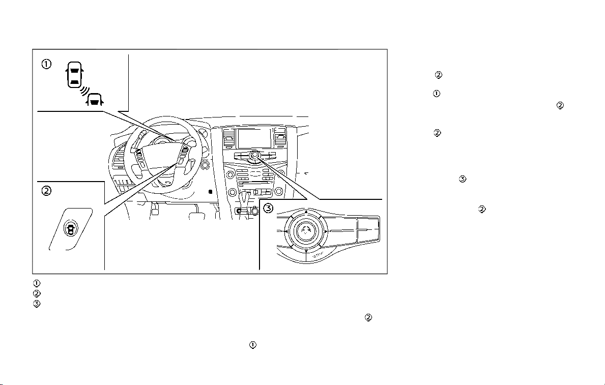
JVS1098X
I-BSI ON indicator light (green)
Dynamic driver assistance switch
Center multi-function control panel
TURNING THE I-BSI SYSTEM ON/
OFF
To turn on the I-BSI system, push the
dynamic driver assistance switch
on
the steering wheel after starting the
engine. The I-BSI ON indicator light
(green)
on the instrumental panel will
illuminate.
Push the dynamic driver assistance
switch
again to turn off the I-BSI
system. The I-BSI ON indicator light
(green)
will turn off.
The dynamic driver assistance switch
is
used for the I-BSI, I-LI and I-DC systems.
When the dynamic driver assistance
switch
is pushed, the I-LI and I-DC
systems will also turn on or off simulta-
neously. The I-BSI system can be indivi-
dually set to on or off on the center
display using the center multi-function
control panel
.
If the system is set to off, the system will
not turn on even if the dynamic driver
assistance switch
is pushed to on. To
set the system to on or off on the center
display, see “How to enable/disable the I-
BSI system” (P.5-44).
Starting and driving 5-43
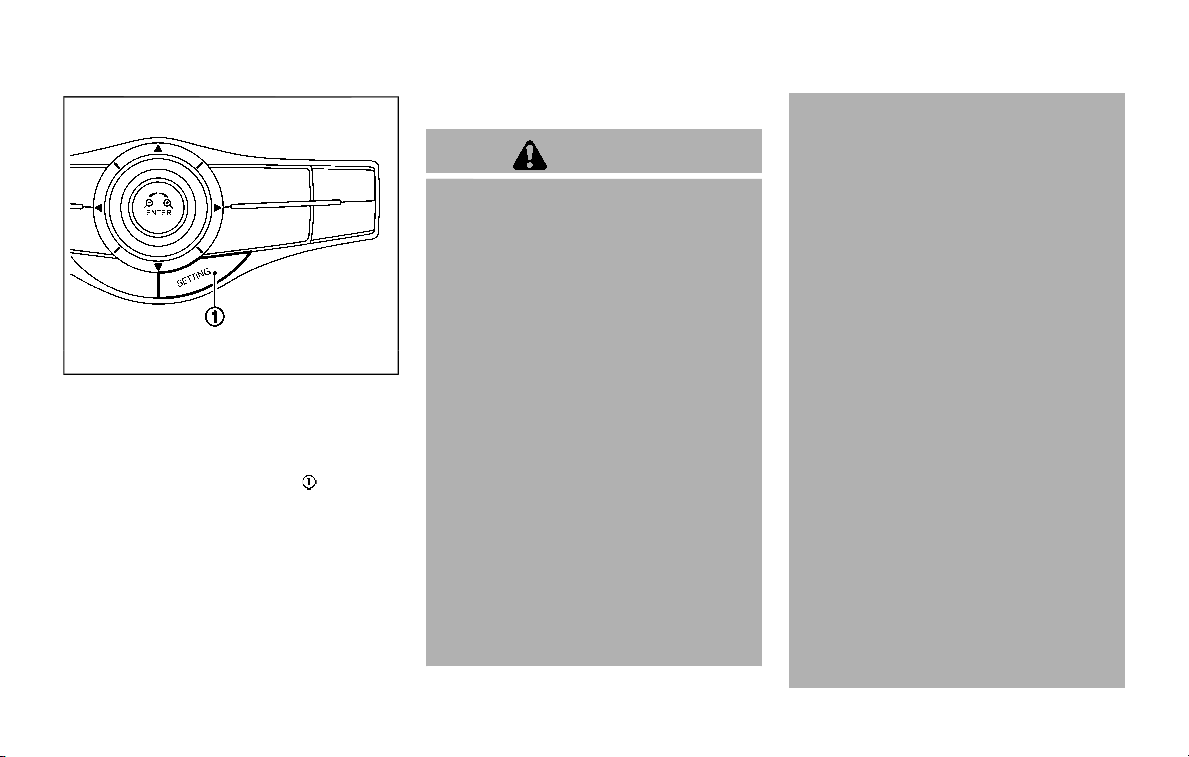
5-44 Starting and driving
JVS1043X
HOW TO ENABLE/DISABLE THE I-BSI
SYSTEM
Perform the following steps to enable or
disable the I-BSI system.
1. Push the SETTING button
.
2. Touch [Driver Assistance].
3. Touch [Blind Spot Assist].
4. Touch [Blind Spot Intervention] to turn
the system ON/OFF.
I-BSI SYSTEM LIMITATIONS
WARNING
Listed below are the system limita-
tions for the I-BSI system. Failure to
operate the vehicle in accordance
with these system limitations could
result in serious injury or death.
. The I-BSI system cannot detect all
vehicles under all conditions.
. The radar sensors may not be
able to detect and activate I-BSI
when certain objects are present
such as:
— Pedestrians, bicycles, animals.
— Vehicles such as motorcycles,
low height vehicles, or high
ground clearance vehicles.
— Vehicles remaining in the de-
tection zone when you accel-
erate from a stop.
— Oncoming vehicles.
— A vehicle merging into an
adjacent lane at a speed ap-
proximately the same as your
vehicle.
— A vehicle approaching rapidly
from behind.
— A vehicle which your vehicle
overtakes rapidly.
— A vehicle that passes through
the detection zone quickly.
. The radar sensor’s detection zone
is designed based on a standard
lane width. When driving in a
wider lane, the radar sensors
may not detect vehicles in an
adjacent lane. When driving in a
narrow lane, the radar sensors
may detect vehicles driving two
lanes away.
. The radar sensors are designed
to ignore most stationary objects,
however objects such as guard-
rails, walls, foliage and parked
vehicles may occasionally be de-
tected. This is a normal operation
condition.
. The camera may not detect lane
markers in the following situa-
tions and the I-BSI system may
not operate properly.
— On roads where there are
multiple parallel lane markers;
lane markers that are faded or
not painted clearly; yellow

painted lane markers; non-
standard lane markers; lane
markers covered with water,
dirt, snow, etc.
— On roads where discontinued
lane markers are still detect-
able.
— On roads where there are
sharp curves.
— On roads where there are
sharply contrasting objects,
such as shadows, snow,
water, wheel ruts, seams or
lines remaining after road re-
pairs.
— On roads where the traveling
lane merges or separates.
— When the vehicle’s traveling
direction does not align with
the lane markers.
— When traveling close to the
vehicle in front of you, which
obstructs the lane camera
unit detection range.
— When rain, snow or dirt ad-
heres to the windshield in
front of a lane camera unit.
— When the headlights are not
bright due to dirt on the lens
or if aiming is not adjusted
properly.
— When strong light enters a
lane camera unit. (For exam-
ple: light directly shines on the
front of the vehicle at sunrise
or sunset.)
— When a sudden change in
brightness occurs. (For exam-
ple: when the vehicle enters or
exits a tunnel or under a
bridge.)
. Do not use the I-BSI system under
the following conditions because
the system may not function
properly.
— During bad weather. (For ex-
ample: rain, fog, snow, etc.)
— When driving on slippery
roads, such as on ice or snow,
etc.
— When driving on winding or
uneven roads.
— When there is a lane closure
due to road repairs.
— When driving in a makeshift or
temporary lane.
— When driving on roads where
the lane width is too narrow.
— When driving with a tire that is
not within normal tire condi-
tions (for example, tire wear,
low tire pressure, installation
of spare tire, tire chains, non-
standard wheels).
— When the vehicle is equipped
with non-original brake parts
or suspension parts.
— When towing a trailer or other
vehicle.
. Excessive noise (for example,
audio system volume, open vehi-
cle window) will interfere with the
chime sound, and it may not be
heard.
Starting and driving 5-45
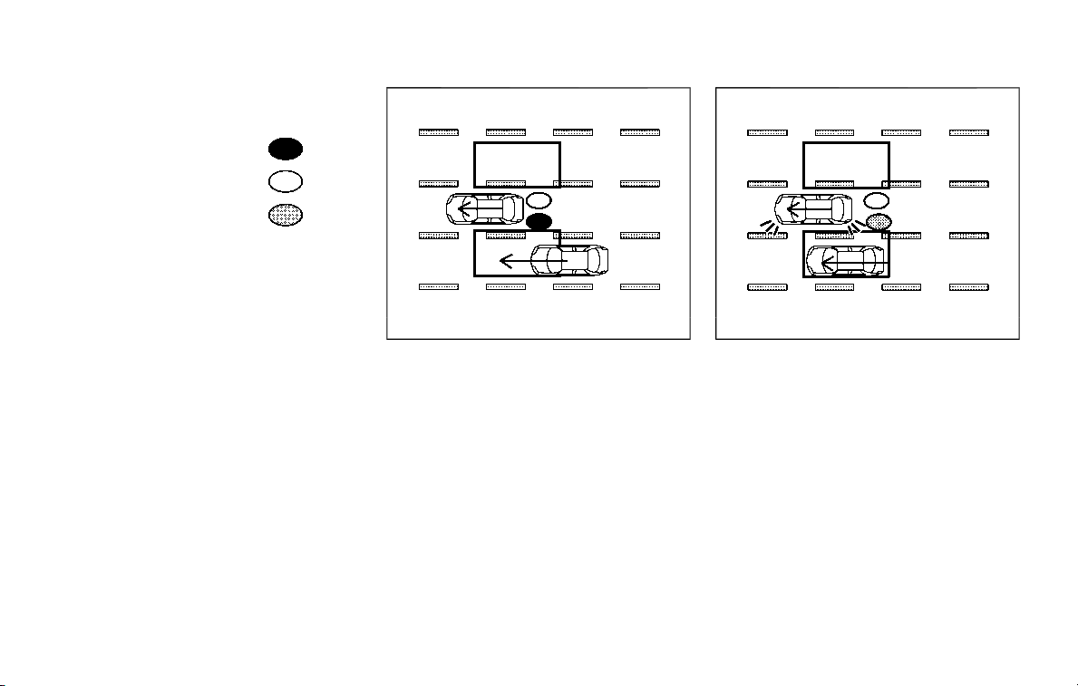
5-46 Starting and driving
I-BSI DRIVING SITUATIONS
Indicator on
Indicator off
Indicator flashing
JVS0737X
Illustration 1 - Approaching from behind
Another vehicle approaching from
behind
Illustration 1: The side indicator light
illuminates if a vehicle enters the detec-
tion zone from behind in an adjacent lane.
JVS0738X
Illustration 2 - Approaching from behind
Illustration 2: If the driver activates the
turn signal then the system chimes
(twice) and the side indicator light flashes.
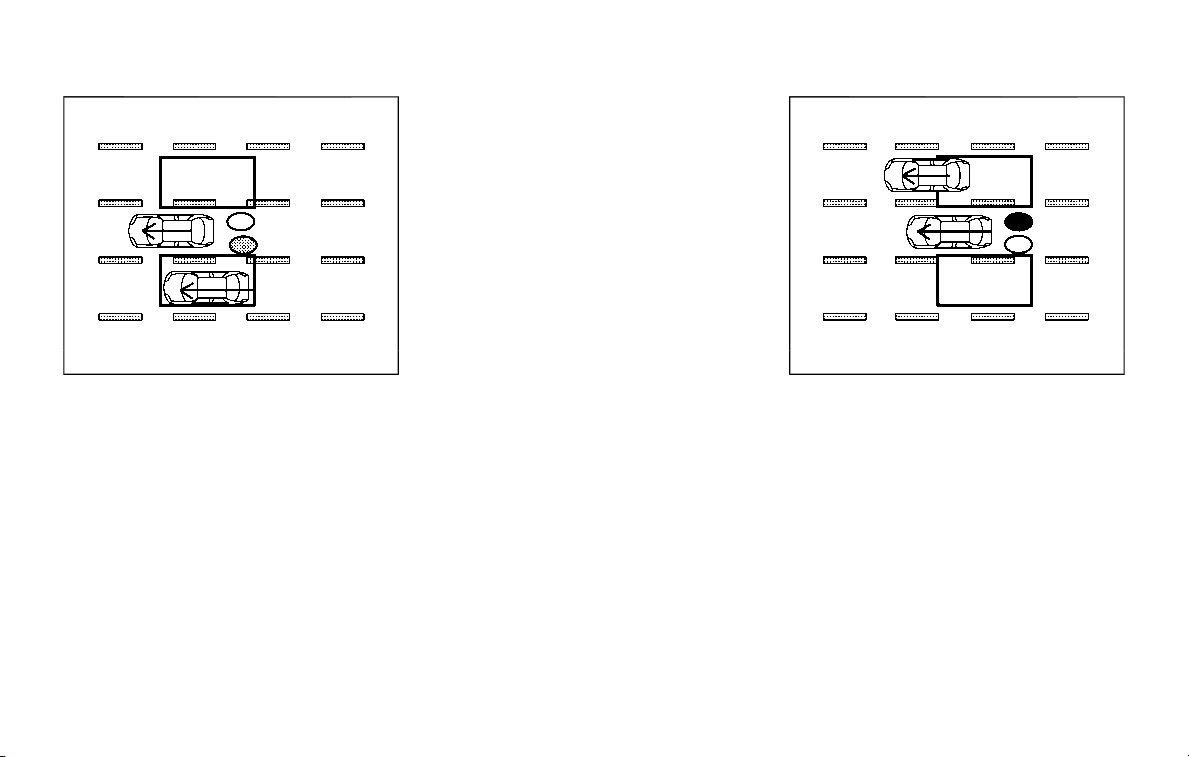
JVS0760X
Illustration 3 - Approaching from behind
Illustration 3: If the I-BSI system is on and
your vehicle approaches a lane marker
while another vehicle is in the detection
zone, the system chimes (three times)
and the side indicator light flashes. Then
the I-BSI system slightly applies the
brakes to help return the vehicle back to
the center of the driving lane.
NOTE:
. The radar sensors may not detect
vehicles which are approaching ra-
pidly from behind.
. If the driver activates the turn signal
before a vehicle enters the detection
zone, the side indicator light will
flash but no chime will sound when
the other vehicle is detected.
JVS0739X
Illustration 4 - Overtaking another vehicle
Overtaking another vehicle
Illustration 4: The side indicator light
illuminates if you overtake a vehicle and
that vehicle stays in the detection zone
for approximately 3 seconds.
Starting and driving 5-47
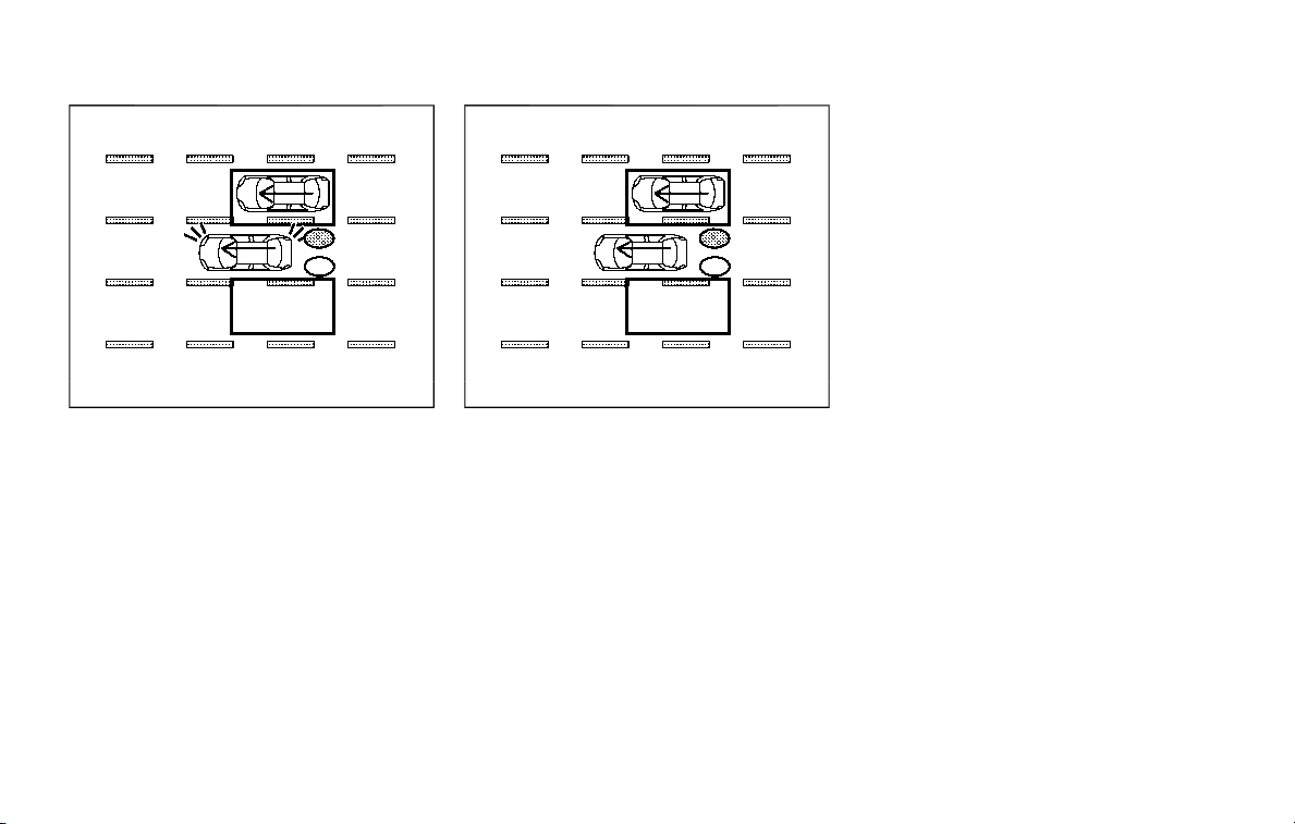
5-48 Starting and driving
JVS0740X
Illustration 5 - Overtaking another vehicle
Illustration 5: If the driver activates the
turn signal while another vehicle is in the
detection zone, then the system chimes
(twice) and the side indicator light flashes.
JVS0761X
Illustration 6 - Overtaking another vehicle
Illustration 6: If the I-BSI system is on and
your vehicle approaches a lane marker
while another vehicle is in the detection
zone, the system chimes (three times)
and the side indicator light flashes. Then,
the I-BSI system slightly applies the
brakes on the appropriate side to help
return the vehicle back to the center of
the driving lane.
NOTE:
. When overtaking several vehicles in
a row, the vehicles after the first
vehicle may not be detected if they
are traveling close together.
. The radar sensors may not detect
slower moving vehicles if they are
passed quickly.
. If the driver activates the turn signal
before a vehicle enters the detection
zone, the side indicator light will
flash but no chime will sound when
the other vehicle is detected.
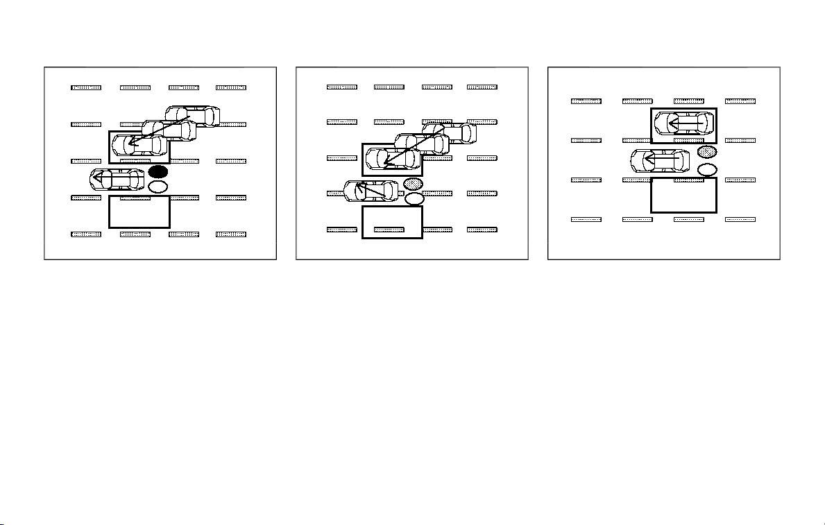
JVS0741X
Illustration 7 - Entering from the side
Entering from the side
Illustration 7: The side indicator light
illuminates if a vehicle enters the detec-
tion zone from either side.
NOTE:
The radar sensors may not detect a
vehicle which is traveling at about the
same speed as your vehicle when it
enters the detection zone.
JVS0742X
Illustration 8 - Entering from the side
Illustration 8: If the driver activates the
turn signal while another vehicle is in the
detection zone, then the side indicator
light flashes and a chime will sound twice.
NOTE:
If the driver activates the turn signal
before a vehicle enters the detection
zone, the side indicator light will flash
but no chime will sound when another
vehicle is detected.
JVS0761X
Illustration 9 - Entering from the side
Illustration 9: If the I-BSI system is on and
your vehicle approaches the lane marker
while another vehicle is in the detection
zone, the system chimes (three times)
and the side indicator light flashes. The I-
BSI system slightly applies the brakes on
the appropriate side to help return the
vehicle back to the center of the driving
lane.
Starting and driving 5-49
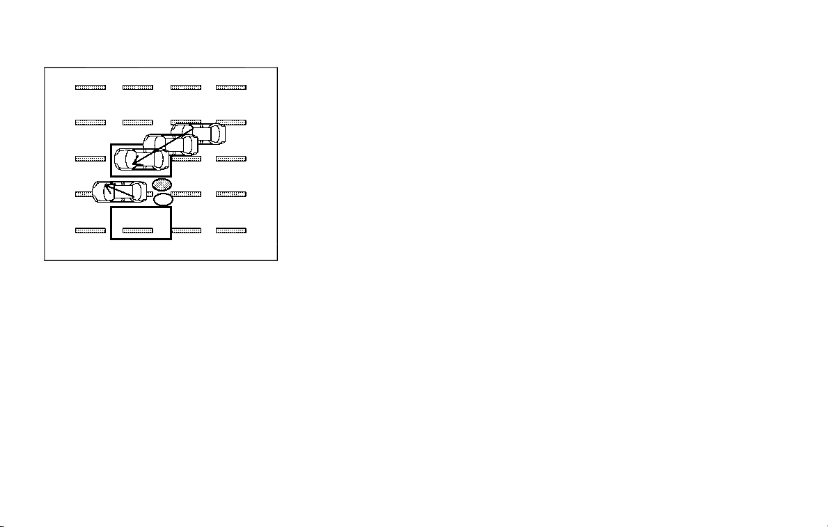
5-50 Starting and driving
JVS0742X
Illustration 10 - Entering from the side
Illustration 10: The I-BSI system will not
operate if your vehicle is on a lane marker
when another vehicle enters the detec-
tion zone. In this case only the BSW
system operates.
NOTE:
. The radar sensors may not detect a
vehicle which is traveling at about
the same speed as your vehicle
when it enters the detection zone.
. If the driver activates the turn signal
before a vehicle enters the detection
zone, the side indicator light will
flash but no chime will sound when
the other vehicle is detected.
. I-BSI braking will not operate or will
stop operating and only a warning
chime will sound under the following
conditions.
— When the brake pedal is de-
pressed.
— When the vehicle is accelerated
during I-BSI system operation.
— When steering quickly
— When the ICC, I-DC, I-FCW or AEB
warnings sound.
— When the hazard warning flashers
are operated.
— When driving on a curve at a high
speed.
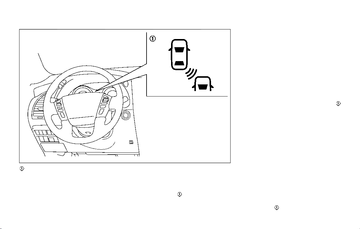
JVS0687X
I-BSI ON indicator light (green)/I-BSI sys-
tem warning light (orange)
SYSTEM TEMPORARILY UNAVAIL-
ABLE
. Under the following conditions, a
chime will sound, the I-BSI ON indica-
tor light (green)
will blink and the I-
BSI system will be turned off auto-
matically. The I-BSI system will not be
available until the conditions no long-
er exist.
— When the VDC system (except TCS
function) or ABS operates.
— When the VDC system is turned off.
Action to take:
Turn off the I-BSI system and turn it on
again when the above conditions no
longer exist.
. Under the following conditions, the I-
BSI system will be turned off auto-
matically, a chime will sound and the I-
BSI system warning light (orange)
will blink. The I-BSI system is not
available until the conditions no long-
er exist.
— When the camera detects that the
interior temperature is high (over
approximately 104°F (40°C)).
— When radar blockage is detected.
The radar sensors may be blocked by
temporary ambient conditions such as
splashing water, mist or fog. The blocked
condition may also be caused by objects
such as ice, frost or dirt obstructing the
radar sensors.
Action to take:
When the above conditions no longer
exist, turn the I-BSI system off and turn
it on again. If the I-BSI system warning
light (orange)
continues to blink even
Starting and driving 5-51
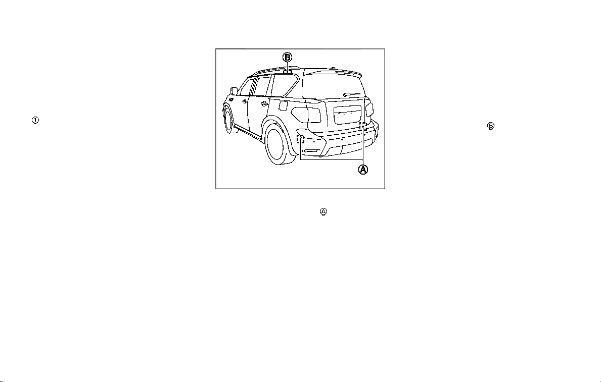
5-52 Starting and driving
after the I-BSI system is turned on again,
stop the vehicle in a safe location, place
the shift lever in the P (Park) position and
turn the engine off. Check for and remove
objects obscuring the radar sensors on
the rear bumper, and restart the engine.
If the I-BSI system warning light (orange)
continues to blink, have the I-BSI
system checked. It is recommended you
visit a NISSAN dealer for this service.
SYSTEM MALFUNCTION
When the I-BSI system malfunctions, it will
be turned off automatically, a chime will
sound and the I-BSI system warning light
(orange) will illuminate.
Action to take:
Stop the vehicle in a safe location, place
the shift lever in the P (Park) position, turn
the engine off and restart the engine.
If the warning light (orange) continues to
illuminate, have the I-BSI system checked.
It is recommended you visit a NISSAN
dealer for this service.
JVS0910X
SYSTEM MAINTENANCE
The two radar sensors for the I-BSI
system are located near the rear bumper.
Always keep the area near the radar
sensors clean.
The radar sensors may be blocked by
temporary ambient conditions such as
splashing water, mist or fog.
The blocked condition may also be
caused by objects such as ice, frost or
dirt obstructing the radar sensors.
Check for and remove objects obstruct-
ing the area around the radar sensors.
Do not attach stickers (including trans-
parent material), install accessories or
apply additional paint near the radar
sensors.
Do not strike or damage the area around
the radar sensors.
It is recommended you visit a NISSAN
dealer if the area around the radar
sensors is damaged due to a collision.
The lane camera unit
for I-BSI system is
located above the inside mirror. To keep
the proper operation of I-BSI and prevent
a system malfunction, be sure to observe
the following:
. Always keep the windshield clean.
. Do not attach a sticker (including
transparent material) or install an
accessory near the camera unit.
. Do not place reflective materials, such
as white paper or a mirror, on the
instrument panel. The reflection of
sunlight may adversely affect the
camera unit’s capability of detecting
the lane markers.
. Do not strike or damage the areas
around the camera unit. Do not touch
the camera lens or remove the screw
located on the camera unit. It is
recommended you contact a NISSAN
dealer if the camera unit is damaged
due to an accident.
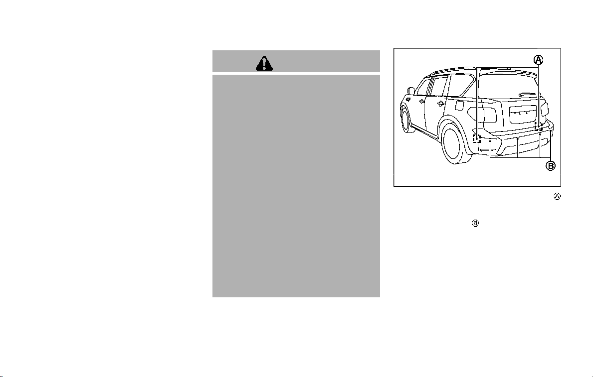
Radio frequency statement
This device complies with part 15 of the
FCC Rules and RSS-310 of Industry Cana-
da.
Operation is subject to the following two
conditions:
1. This device may not cause harmful
interference.
2. This device must accept any interfer-
ence received, including interference
that may cause undesired operation.
Frequency of operation: 24.05GHz —
24.25GHz
Field Strength: Not greater than 2.5V/m
peak (0.25V/m average) at a distance of 3
m
The manufacturer is not responsible for
any radio or TV interference caused by
unauthorized modifications to this equip-
ment. Such modifications could void the
user’s authority to operate the equip-
ment.
WARNING
Failure to follow the warnings and
instructions for proper use of the I-BI
system could result in serious injury
or death.
. The I-BI system is not a replace-
ment for proper driving proce-
dure, is not designed to prevent
contact with vehicles or objects
and does not provide full brake
power. When backing out of park-
ing spaces, always use the inside
and rear mirrors and turn and
look in the direction you will
move. Never rely solely on the I-
BI system.
. There is a limitation to the detec-
tion capability of the radar or the
sonar. Using the I-BI system un-
der some road, ground, traffic or
weather conditions could lead to
improper system operation. Al-
ways rely on your own operation
to avoid accidents.
The I-BI system can help alert the driver of
an approaching vehicle or objects behind
the vehicle when the driver is backing out
of a parking space.
JVS0912X
The I-BI system uses radar sensors
installed on both sides near the rear
bumper to detect an approaching vehicle
and sonar sensors
to detect objects in
the rear.
Starting and driving 5-53
INTELLIGENT BACK-UP
INTERVENTION (I-BI) (if so equipped)
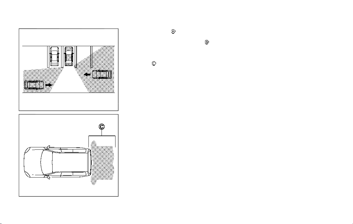
5-54 Starting and driving
JVS0173X
JVS0698X
The radar sensors detect an approach-
ing vehicle from up to approximately 49 ft
(15 m) away. The sonar sensors
detect
stationary objects behind the vehicle up
to approximately 4.9 ft (1.5 m). Refer to the
illustration for approximate zone cover-
age areas
.
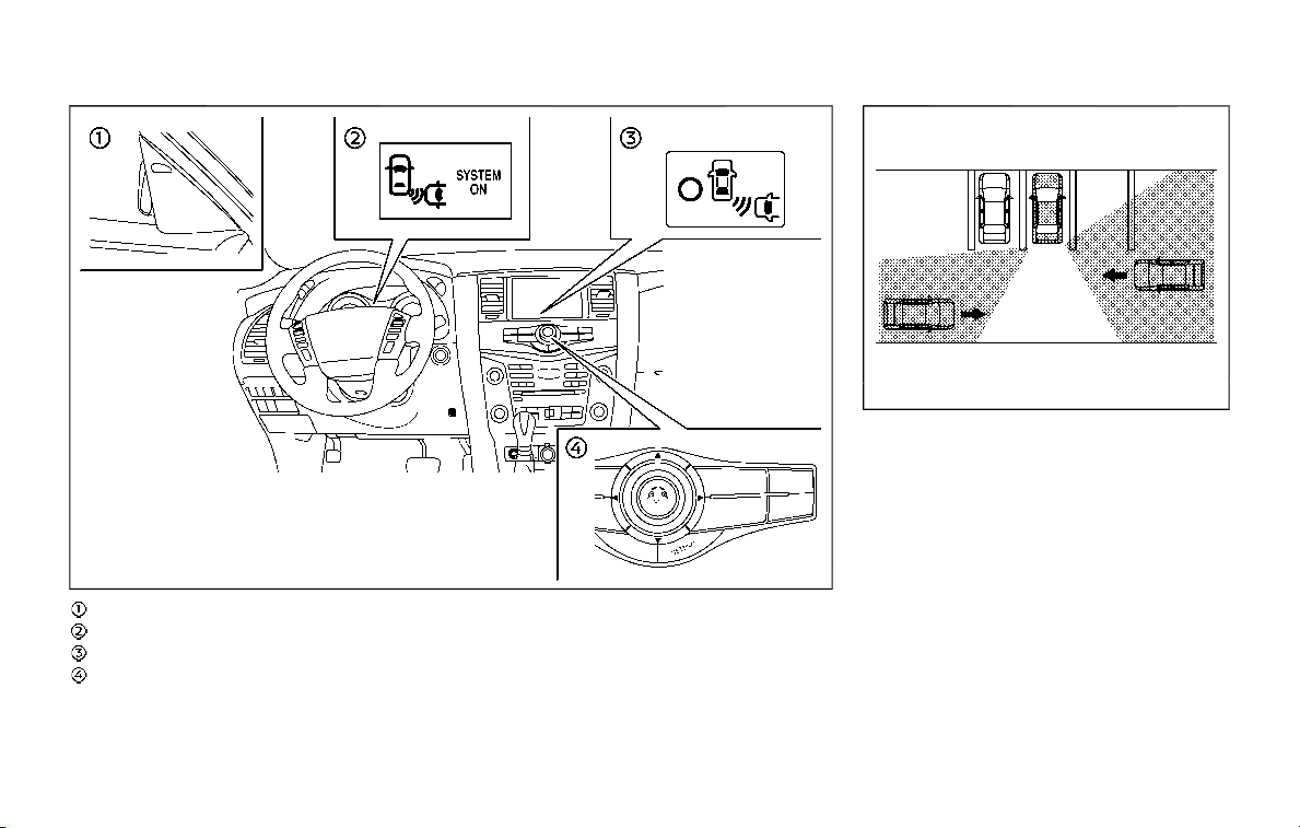
JVS1099X
Side indicator light
I-BI system indicator
I-BI system key (on the center display)
Center multi-function control panel
JVS0173X
I-BI SYSTEM OPERATION
When the shift lever is in the R (Reverse)
position and the vehicle speed is less than
approximately 5 MPH (8 km/h), the I-BI
system operates.
If the radar detects a vehicle approaching
from the side or the sonar detects close
stationary objects behind the vehicle, the
system gives visual and audible warnings.
If the driver does not apply the brakes, the
system automatically applies the brake
for a moment when the vehicle is moving
backwards. After the automatic brake
application, the driver must depress the
brake pedal to maintain brake pressure. If
the driver’s foot is on the accelerator
Starting and driving 5-55

5-56 Starting and driving
pedal, the system pushes the accelerator
upward before applying the brake. If you
continue to accelerate, the system will
not engage the brake.
JVS0304X
Center display
JVS0197X
I-BI ON indicator
When the shift lever is placed in the R
(Reverse) position, the indicator on the I-
BI system key
illuminates on the center
display and I-BI ON indicator appears on
the vehicle information display.
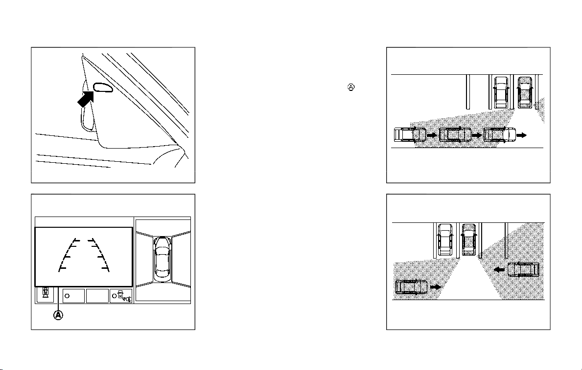
SSD1086
Side indicator light
JVS0307X
If the radar detects an approaching
vehicle from the side, the system chimes
(once), the side indicator light on the side
the vehicle is approaching from flashes
and a yellow rectangular frame
ap-
pears on the center display.
JVS0172X
Illustration 1
JVS0173X
Illustration 2
Starting and driving 5-57

5-58 Starting and driving
. In the case of several vehicles ap-
proaching in a row (Illustration 1) or in
the opposite direction (Illustration 2), a
chime may not be issued to the I-BI
system after the first vehicle passes
the sensors.
. The sonar system chime indicating
there is an object behind the vehicle
has a higher priority than the I-BI
chime (single beep) indicating an ap-
proaching vehicle. If the sonar system
detects an object behind the vehicle
and the I-BI system detects an ap-
proaching vehicle at the same time,
the following indications are provided:
— The sonar system chime sounds
— The side indicator light on the side
of the approaching vehicle flashes,
and
— A yellow rectangular frame appears
in the center display.
JVS0307X
If an approaching vehicle or close object
behind the vehicle is detected when your
vehicle is backing up, a red frame
will
appear in the center display and the
system will chime three times. Then, the
brakes will be applied momentarily. After
the automatic brake application, the dri-
ver must depress the brake pedal to
maintain brake pressure.
If the driver’s foot is on the accelerator
pedal, the system moves the accelerator
pedal upward before the braking is ap-
plied. However, if you continue to accel-
erate, the system will not engage the
brakes.
The I-BI system does not operate if the
object is very close to the bumper.
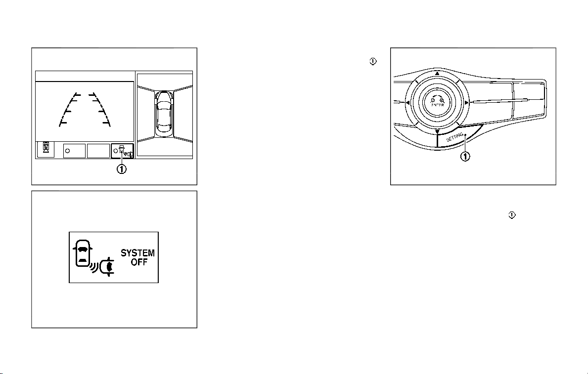
JVS0304X
JVS0182X
I-BI OFF indicator
The I-BI system can be turned off tem-
porarily by touching the I-BI system key
on the center display. The indicator on
the I-BI system key turns off and the I-BI
OFF indicator appears on the vehicle
information display.
When the shift lever is placed in the R
(Reverse) position again, the I-BI system is
turned on.
HOW TO ENABLE/DISABLE THE I-BI
SYSTEM
The I-BI system can be turned off perma-
nently using the center display.
JVS1043X
Perform the following steps to enable or
disable the I-BI system.
1. Push the SETTING button
.
2. Touch [Camera/Sonar].
3. Touch [Camera].
4. Touch [Back-up Collision Intervention]
to turn the system ON/OFF.
Starting and driving 5-59
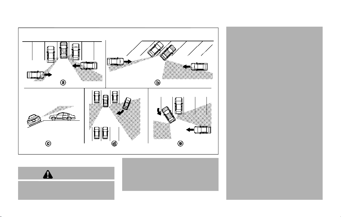
5-60 Starting and driving
JVS0479X
I-BI SYSTEM PRECAUTIONS
WARNING
Listed below are the system limita-
tions for the I-BI system. Failure to
operate the vehicle in accordance
with these system limitations could
result in serious injury or death.
. Always check your surroundings
and turn to check what is behind
you before backing up.
. The radar sensors detect ap-
proaching (moving) vehicles. The
radar sensors cannot detect
every object such as:
— Pedestrians, bicycles, animals
or child operated toy vehicles
— A vehicle that passing at
speeds greater than approxi-
mately 15 MPH (24 km/h)
. The radar sensors may not detect
approaching vehicles in certain
situations:
— Illustration a. When a vehicle
parked next to you obstructs
the beam of the radar sensor.
— Illustration b. When the vehicle
is parked in an angled parking
space.
— Illustration c. When the vehicle
is parked on inclined ground.
— Illustration d. When an ap-
proaching vehicle turns into
your vehicle’s parking lot aisle.
— Illustration e. When the angle
formed by your vehicle and
approaching vehicle is small.
. The following conditions may re-
duce the ability of the radar
sensors to detect other vehicles:
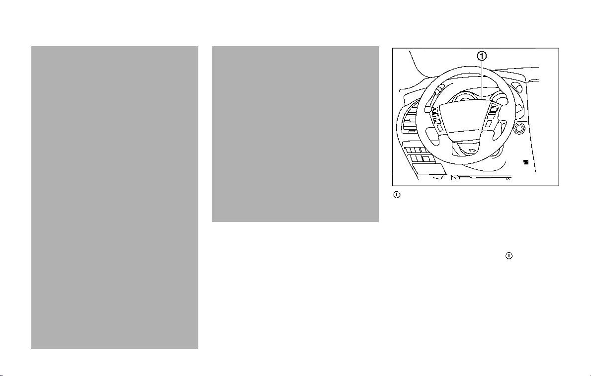
— Severe weather
— Road spray
— Ice/frost/dirt build up on the
vehicle
. Do not attach stickers (including
transparent material), install ac-
cessories or apply additional
paint near the radar sensors.
These conditions may reduce the
ability of the radar sensors to
detect other vehicles.
. The sonar sensors detect station-
ary objects behind the vehicle.
The sonar sensor may not detect:
— Small or moving objects
— Wedge-shaped objects
— Object close to the bumper
(less than approximately 1 ft
(30 cm))
— Thin objects such as rope, wire
and chain, etc.
. The brake engagement by the I-
BI system is not as effective on a
slope as it is on flat ground. When
on a steep slope the system may
not function properly.
. Do not use the I-BI system under
the following conditions because
the system may not function
properly.
— When driving with a tire that is
not within normal tire condi-
tions (for example, tire wear,
low tire pressure, installation
of spare tire, tire chains, non-
standard wheels).
— When the vehicle is equipped
with non-original brake parts
or suspension parts.
— When towing a trailer or other
vehicle.
. Excessive noise (for example,
audio system volume, open vehi-
cle window) will interfere with the
chime sound, and it may not be
heard.
JVS0689X
Vehicle information display
SYSTEM TEMPORARILY UNAVAIL-
ABLE
Under the following conditions, a chime
will sound and “BCI NOT AVAILABLE”
warning message will appear in the
vehicle information display
, and the I-
BI system will be turned off automatically.
. If the vehicle is parked in direct sun-
light under high temperature condi-
tions (over approximately 104°F
(40°C)).
. When side radar blockage is detected.
Turn off the I-BI system and turn it on
again when the above conditions no
longer exist.
Starting and driving 5-61
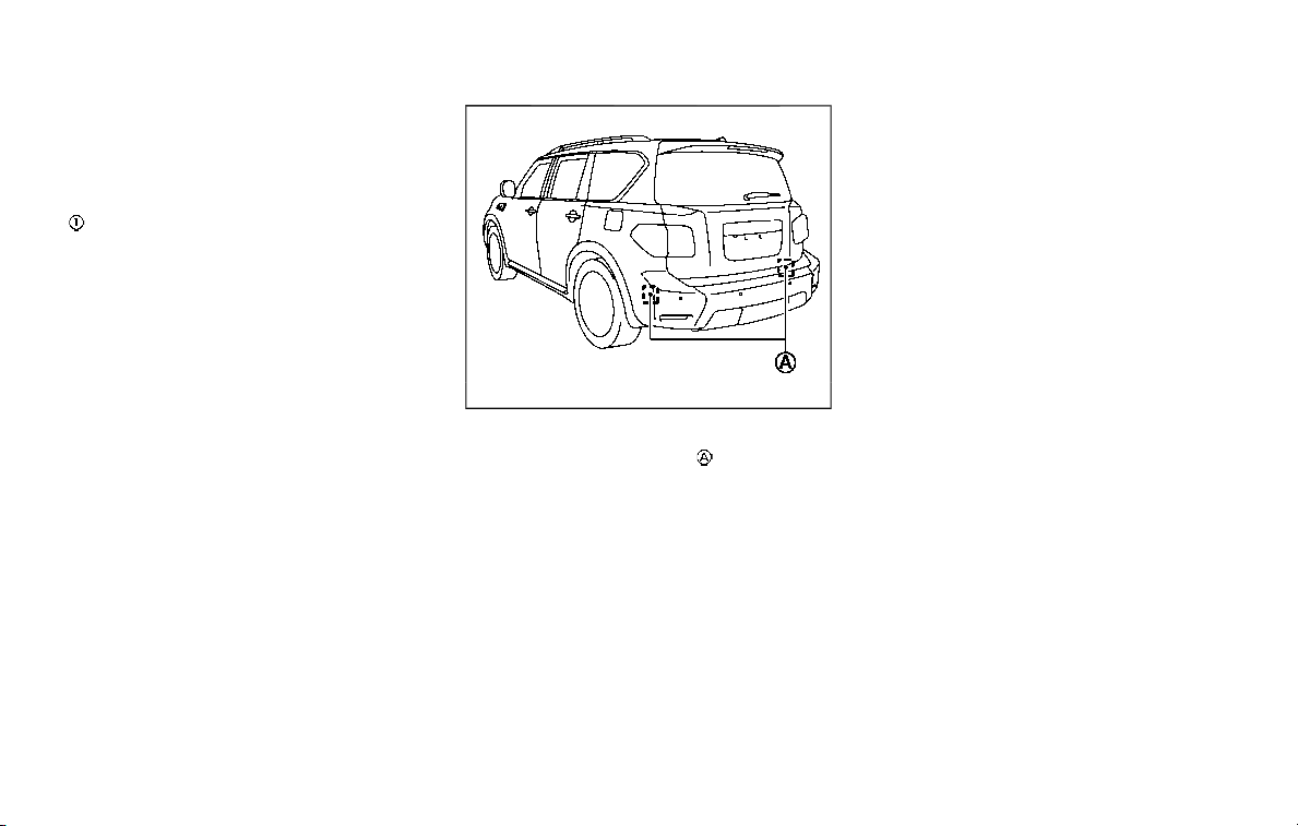
5-62 Starting and driving
SYSTEM MALFUNCTION
If the I-BI system malfunctions, it will turn
off automatically, a chime will sound and
“BCI MALFUNCTION” warning message will
appear in the vehicle information display
.
Action to take
Stop the vehicle in a safe location and
place the shift lever in the P (Park)
position. Turn the engine off and restart
the engine. If the warning message con-
tinues to appear, have the system
checked. It is recommended you visit a
NISSAN dealer for this service.
JVS0908X
SYSTEM MAINTENANCE
The two radar sensors for the I-BI
system are located near the rear bumper.
Always keep the area near the radar
sensors clean.
The radar sensors may be blocked by
temporary ambient conditions such as
splashing water, mist or fog.
The blocked condition may also be
caused by objects such as ice, frost or
dirt obstructing the radar sensors.
Check for and remove objects obstruct-
ing the area around the radar sensors.
Do not attach stickers (including trans-
parent material), install accessories or
apply additional paint near the radar
sensors.
Do not strike or damage the area around
the radar sensors.
It is recommended you visit a NISSAN
dealer if the area around the radar
sensors is damaged due to a collision.
Radio frequency statement
This device complies with part 15 of the
FCC Rules and RSS-310 of Industry Cana-
da.
Operation is subject to the following two
conditions:
1. This device may not cause harmful
interference.
2. This device must accept any interfer-
ence received, including interference
that may cause undesired operation.
Frequency of operation: 24.05GHz —
24.25GHz
Field Strength: Not greater than 2.5V/m
peak (0.25V/m average) at a distance of 3
m
The manufacturer is not responsible for
any radio or TV interference caused by
unauthorized modifications to this equip-
ment. Such modifications could void the
user’s authority to operate the equip-
ment.

WARNING
Failure to follow the warnings and
instructions for proper use of the ICC
system could result in serious injury
or death.
. ICC is not a collision avoidance or
warning device. For highway use
only and it is not intended for
congested areas or city driving.
Failure to apply the brakes could
result in an accident.
. Always observe posted speed
limits and do not set the speed
over them.
. Always drive carefully and atten-
tively when using either cruise
control mode. Read and under-
stand the Owner’s Manual thor-
oughly before using the cruise
control. To avoid serious injury
or death, do not rely on the
system to prevent accidents or
to control the vehicle’s speed in
emergency situations. Do not use
cruise control except in appropri-
ate road and traffic conditions.
. In the conventional (fixed speed)
cruise control mode, a warning
chime will not sound to warn you
if you are too close to the vehicle
ahead. Pay special attention to
the distance between your vehi-
cle and the vehicle ahead of you
or a collision could occur.
The ICC system maintains a selected
distance from the vehicle in front of you
within the speed range of 0 to 90 MPH (0
to 144 km/h) up to the set speed. The set
speed can be selected by the driver
between 20 to 90 MPH (32 to 144 km/h).
The vehicle travels at a set speed when
the road ahead is clear.
The ICC system can be set to one of two
cruise control modes.
. Vehicle-to-vehicle distance control
mode:
For maintaining a selected distance
between your vehicle and the vehicle
in front of you up to the preset speed.
. Conventional (fixed speed) cruise con-
trol mode:
For cruising at a preset speed.
Starting and driving 5-63
INTELLIGENT CRUISE CONTROL (ICC)
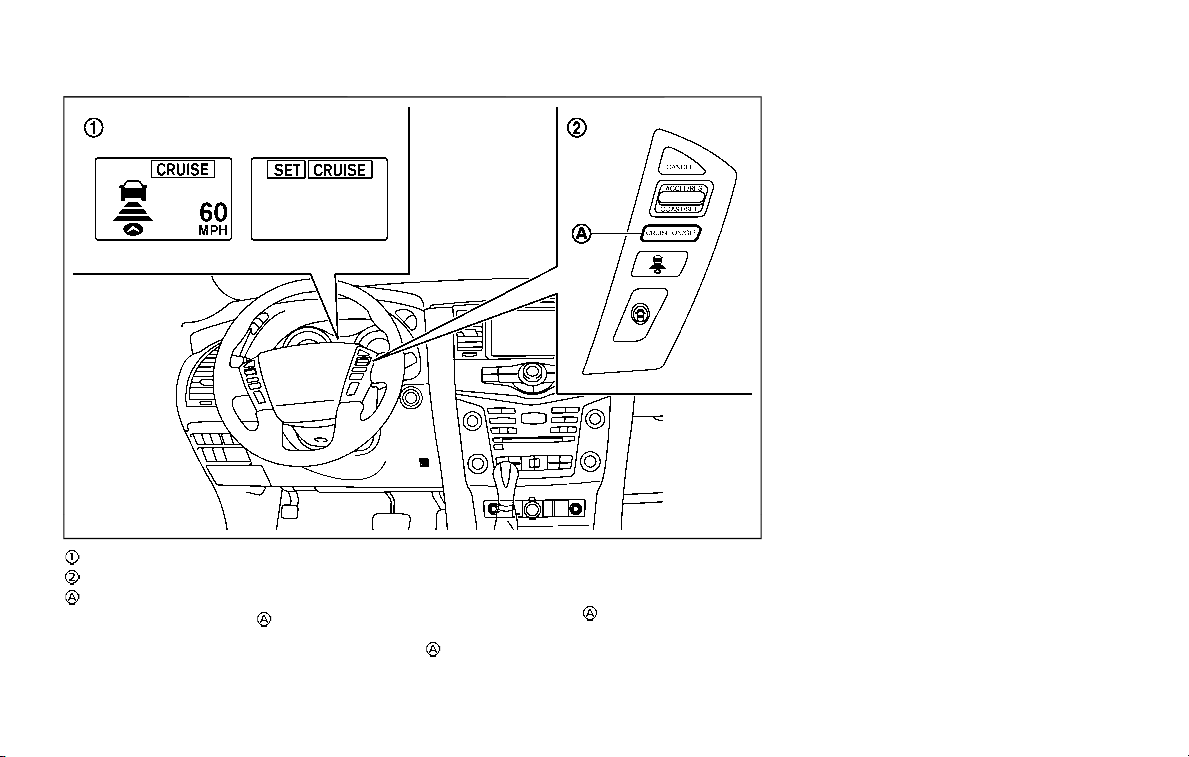
5-64 Starting and driving
JVS0888X
Displays and indicators
ICC switches
MAIN (ON·OFF) switch
Push the MAIN switch to choose the
cruise control mode between the vehicle-
to-vehicle distance control mode and the
conventional (fixed speed) cruise control
mode.
Once a control mode is activated, it
cannot be changed to the other cruise
control mode. To change the mode, push
the MAIN switch
once to turn the
system off. Then push the MAIN switch
again to turn the system back on and
select the desired cruise control mode.
Always confirm the setting in the ICC
system display.
For the vehicle-to-vehicle distance con-
trol mode, see “Vehicle-to-vehicle dis-
tance control mode” (P.5-65).
For the conventional (fixed speed) cruise
control mode, see “Conventional (fixed
speed) cruise control mode” (P.5-81).
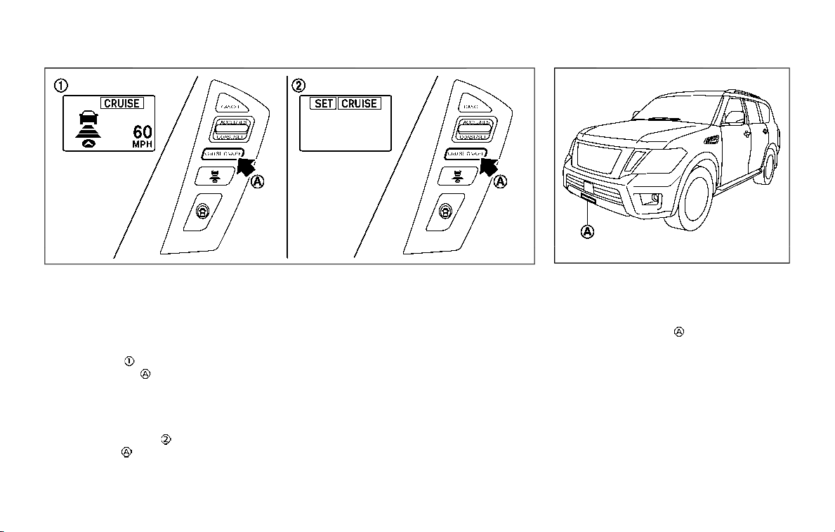
SSD1051
HOW TO SELECT THE CRUISE CON-
TROL MODE
Selecting vehicle-to-vehicle dis-
tance control mode
To choose the vehicle-to-vehicle distance
control mode
, quickly push and release
the MAIN switch
.
Selecting the conventional (fixed
speed) cruise control mode
To choose the conventional (fixed speed)
cruise control mode
, push and hold the
MAIN switch
for longer than approxi-
mately 1.5 seconds. See “Conventional
(fixed speed) cruise control mode” (P.5-81).
VEHICLE-TO-VEHICLE DISTANCE
CONTROL MODE
In the vehicle-to-vehicle distance control
mode, the ICC system automatically
maintains a selected distance from the
vehicle traveling in front of you according
to that vehicle’s speed (up to the set
speed), or at the set speed when the road
ahead is clear.
JVS0913X
The system is intended to enhance the
operation of the vehicle when following a
vehicle traveling in the same lane and
direction.
If the radar sensor
detects a slower
moving vehicle ahead, the system will
reduce the vehicle speed so that your
vehicle follows the vehicle in front at the
selected distance.
The system automatically controls the
throttle and applies the brakes (up to
approximately 40% of vehicle braking
power) if necessary.
The detection range of the sensor is
approximately 650 ft (200 m) ahead.
Starting and driving 5-65
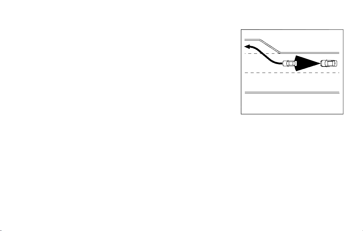
5-66 Starting and driving
Vehicle-to-vehicle distance control
mode operation
The vehicle-to-vehicle distance control
mode is designed to maintain a selected
distance and reduce the speed to match
the slower vehicle ahead; the system will
decelerate the vehicle as necessary and if
the vehicle ahead comes to a stop, the
vehicle decelerates to a standstill. How-
ever, the ICC system can only apply up to
approximately 40% of the vehicle’s total
braking power. This system should only
be used when traffic conditions allow
vehicle speeds to remain fairly constant
or when vehicle speeds change gradually.
If a vehicle moves into the traveling lane
ahead or if a vehicle traveling ahead
rapidly decelerates, the distance between
vehicles may become closer because the
ICC system cannot decelerate the vehicle
quickly enough. If this occurs, the ICC
system will sound a warning chime and
blink the system display to notify the
driver to take necessary action.
The system will cancel and a warning
chime will sound if the speed is below
approximately 15 MPH (24 km/h) and a
vehicle is not detected ahead. The system
will also disengage when the vehicle goes
above the maximum set speed.
See “Approach warning” (P.5-73).
The following items are controlled in the
vehicle-to-vehicle distance control mode:
. When there are no vehicles traveling
ahead, the vehicle-to-vehicle distance
control mode maintains the speed set
by the driver. The set speed range is
between approximately 20 and 90
MPH (32 and 144 km/h).
. When there is a vehicle traveling
ahead, the vehicle-to-vehicle distance
control mode adjusts the speed to
maintain the distance, selected by
driver, from the vehicle ahead. The
adjusting speed range is up to the set
speed. If the vehicle ahead comes to a
stop, the vehicle decelerates to a
standstill within the limitations of the
system. The system will cancel once it
judges a standstill with a warning
chime.
. When the vehicle traveling ahead has
moved out from its lane of travel, the
vehicle-to-vehicle distance control
mode accelerates and maintains ve-
hicle speed up to the set speed.
The ICC system does not control vehicle
speed or warn you when you approach
stationary and slow moving vehicles. You
must pay attention to vehicle operation
to maintain proper distance from vehicles
ahead when approaching toll gates or
traffic congestion.
SSD0254
When driving on the freeway at a set
speed and approaching a slower traveling
vehicle ahead, the ICC system will adjust
the speed to maintain the distance,
selected by the driver, from the vehicle
ahead. If the vehicle ahead changes lanes
or exits the freeway, the ICC system will
accelerate and maintain the speed up to
the set speed. Pay attention to the driving
operation to maintain control of the
vehicle as it accelerates to the set speed.
The vehicle may not maintain the set
speed on winding or hilly roads. If this
occurs, you will have to manually control
the vehicle speed.
Normally when controlling the distance to
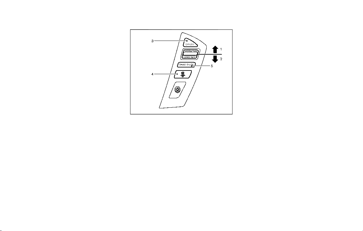
a vehicle ahead, this system automati-
cally accelerates or decelerates your ve-
hicle according to the speed of the
vehicle ahead. Depress the accelerator
to properly accelerate your vehicle when
acceleration is required for a lane change.
Depress the brake pedal when decelera-
tion is required to maintain a safe dis-
tance to the vehicle ahead due to its
sudden braking or if a vehicle cuts in.
Always stay alert when using the ICC
system.
SSD0964
Vehicle-to-vehicle distance control
mode switches
The system is operated by a MAIN switch
and four control switches, all mounted on
the steering wheel.
1. ACCELERATE/RESUME switch:
Resumes set speed or increases speed
incrementally.
2. COAST/SET switch:
Sets desired cruise speed, reduces
speed incrementally.
3. CANCEL switch:
Deactivates the system without eras-
ing the set speed.
4. DISTANCE switch:
Changes the vehicle’s following dis-
tance:
.
Long
.
Middle
.
Short
5. MAIN switch:
Master switch to activate the system
Starting and driving 5-67
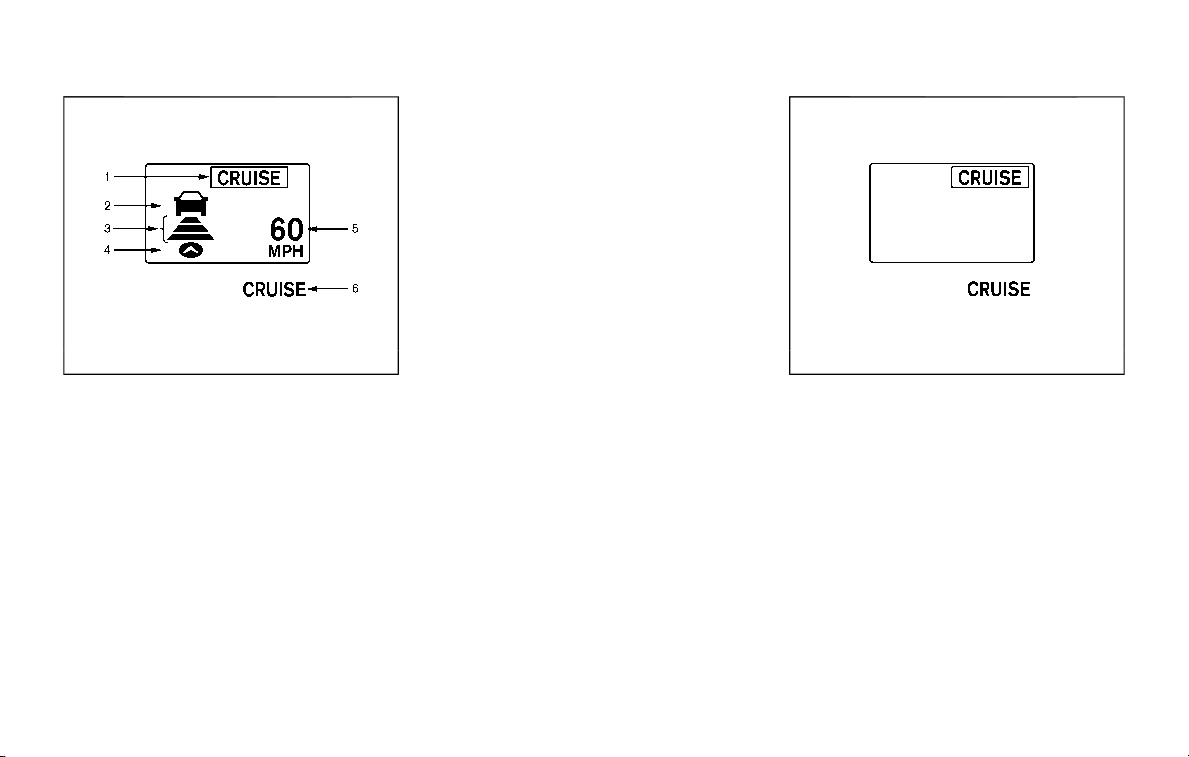
5-68 Starting and driving
SSD1104
Vehicle-to-vehicle distance control
mode display and indicators
The display is located between the speed-
ometer and tachometer.
1. MAIN switch indicator:
Indicates that the MAIN switch is ON.
2. Vehicle ahead detection indicator:
Indicates whether it detects a vehicle
in front of you.
3. Set distance indicator:
Displays the selected distance be-
tween vehicles set with the DISTANCE
switch.
4. Indicates your vehicle
5. Set vehicle speed indicator:
Indicates the set vehicle speed.
For Canadian models, the speed is
displayed in km/h.
6. ICC system warning light (orange):
The light comes on if there is a
malfunction in the ICC system.
SSD0979
When the ignition switch is pushed to the
ON position, the indicators come on as
illustrated to check for a burned-out bulb,
and it turns off when the engine is
started.
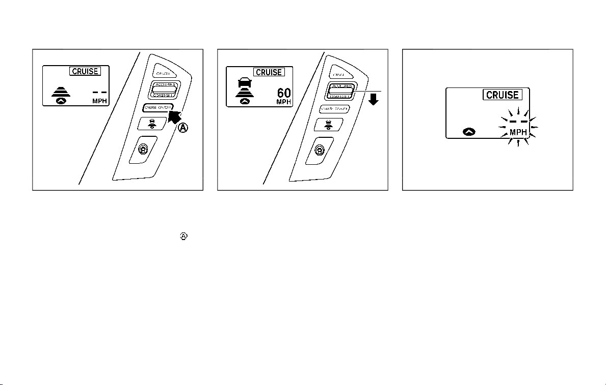
SSD1052
Operating vehicle-to-vehicle dis-
tance control mode
To turn on the cruise control, quickly
push and release the MAIN switch
on.
The MAIN switch indicator, set distance
indicator and set vehicle speed indicator
come on and in a standby state for
setting.
SSD1053
To set cruising speed, accelerate your
vehicle to the desired speed, push the
COAST/SET switch and release it. (Vehicle
ahead detection indicator, set distance
indicator and set vehicle speed indicator
come on.) Take your foot off the accel-
erator pedal. Your vehicle will maintain
the set speed.
SSD1105
When the COAST/SET switch is pushed
under the following conditions, the sys-
tem cannot be set and the ICC indicators
will blink for approximately 2 seconds:
. When traveling below 20 MPH (32
km/h) and the vehicle ahead is not
detected
. When the shift lever is not in the D
(Drive) or manual shift mode
. When the parking brake is applied
. When the brakes are operated by the
driver
Starting and driving 5-69
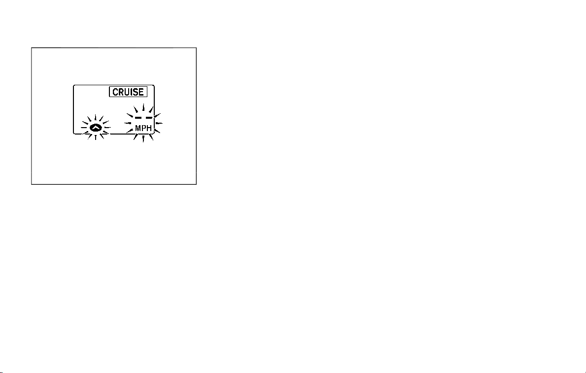
5-70 Starting and driving
SSD1106
When the COAST/SET switch is pushed
under the following conditions, the sys-
tem cannot be set.
A warning chime will sound and the ICC
indicators will blink.
. When the SNOW mode is pushed
(SNOW mode switch) (To use the ICC
system, turn off the SNOW mode
switch, push the MAIN switch to turn
off the ICC and reset the ICC switch by
pushing the MAIN switch again.)
For details about the SNOW mode
switch, see “SNOW mode” (P.5-127).
. When the 4WD shift switch is in the 4H
or 4L position. (To use the ICC system,
place the 4WD shift switch in the AUTO
position, push the MAIN switch to turn
off the ICC system and reset the ICC
switch by pushing the MAIN switch
again (for 4WD models).
For details about the 4WD shift switch,
see “NISSAN all-mode 4WD®” (P.5-116).
. When the VDC system is off (To use
the ICC system, turn on the VDC
system. Push the MAIN switch to turn
off the ICC system and reset the ICC
switch by pushing the MAIN switch
again.)
For details about the VDC system, see
“Vehicle Dynamic Control (VDC) sys-
tem” (P.5-133).
. When ABS or VDC (including the trac-
tion control system) is operating
. When a wheel is slipping (To use the
ICC system, make sure the wheels are
no longer slipping. Push the MAIN
switch to turn off the ICC, and reset
the ICC system by pushing the MAIN
switch again.)
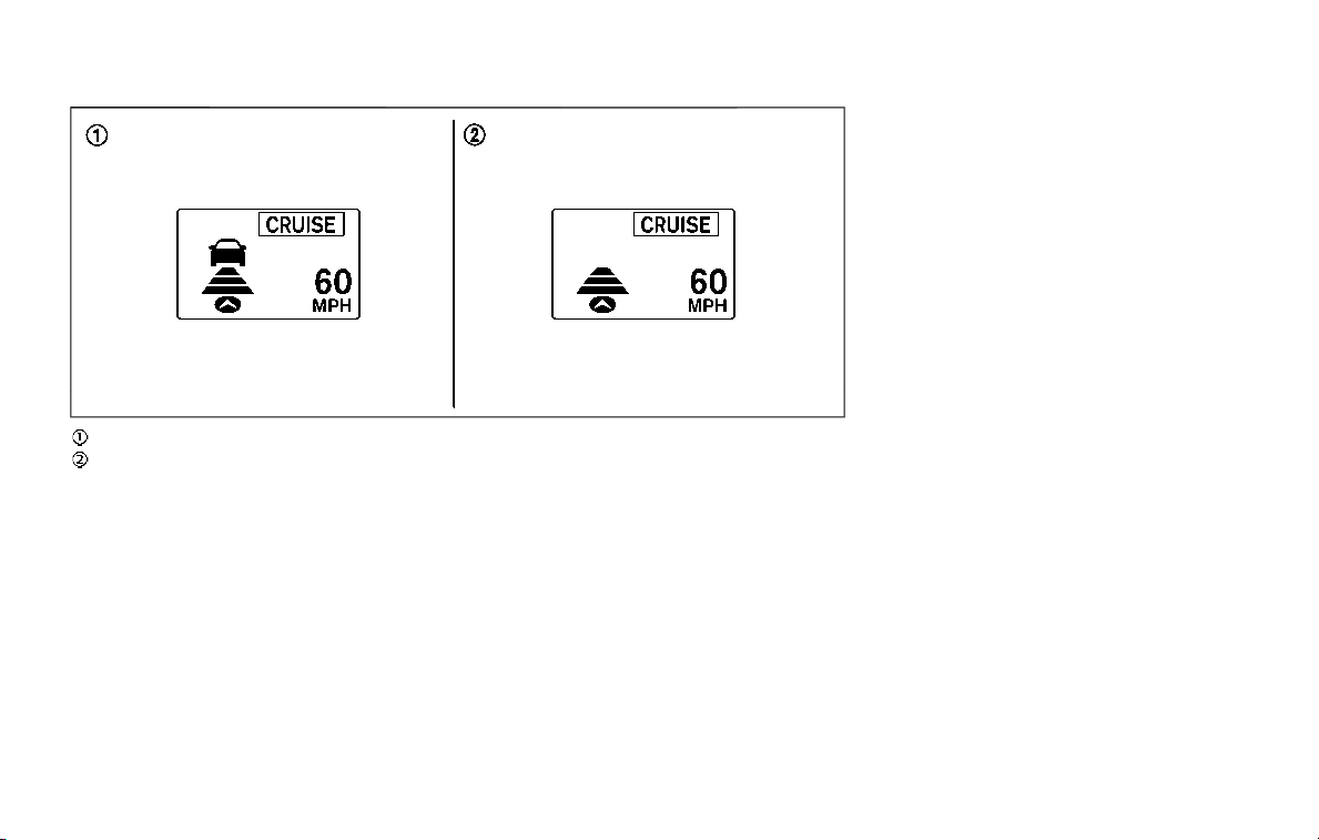
SSD1107
System set display with vehicle ahead
System set display without vehicle ahead
The driver sets the desired vehicle speed
based on the road conditions. The ICC
system maintains the set vehicle speed,
similar to standard cruise control, as long
as no vehicle is detected in the lane
ahead.
The ICC system displays the set speed.
Vehicle detected ahead:
When a vehicle is detected in the lane
ahead, the ICC system decelerates the
vehicle by controlling the throttle and
applying the brakes to match the speed
of a slower vehicle ahead. The system
then controls the vehicle speed based on
the speed of the vehicle ahead to main-
tain the driver selected distance.
NOTE:
. The stoplights of the vehicle come
on when braking is performed by
the ICC system.
. When the brake operates, a noise
may be heard and/or vibration may
be felt. This is not a malfunction.
When a vehicle ahead is detected, the
vehicle ahead detection indicator comes
on. The ICC system will also display the
set speed and selected distance.
Vehicle ahead not detected:
When a vehicle is no longer detected
ahead, the ICC system gradually acceler-
ates your vehicle to resume the pre-
viously set vehicle speed. The ICC
system then maintains the set speed.
When a vehicle is no longer detected the
vehicle ahead detection indicator turns
off.
If a vehicle ahead appears during accel-
eration to the set vehicle speed or any
time the ICC system is in operation, the
system controls the distance to that
vehicle.
When a vehicle is no longer detected
under approximately 15 MPH (24 km/h),
the system will be canceled.
Starting and driving 5-71
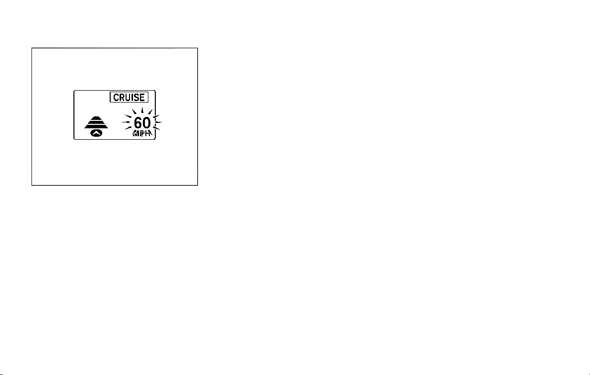
5-72 Starting and driving
SSD1108
When passing another vehicle, the set
speed indicator will flash when the vehicle
speed exceeds the set speed. The vehicle
detect indicator will turn off when the
area ahead of the vehicle is open. When
the pedal is released, the vehicle will
return to the previously set speed.
Even though your vehicle speed is set in
the ICC system, you can depress the
accelerator pedal when it is necessary to
accelerate your vehicle rapidly.
How to change set vehicle speed
To cancel the preset speed, use any of
these methods:
. Push the CANCEL switch. The set
vehicle speed indicator will go out.
. Tap the brake pedal. The set vehicle
speed indicator will go out.
. Turn the MAIN switch off. Both the
MAIN switch indicator and set vehicle
speed indicator will go out.
To reset at a faster cruising speed, use
one of the following methods:
. Depress the accelerator pedal. When
the vehicle attains the desired speed,
push and release the COAST/SET
switch.
. Push and hold the ACCELERATE/RE-
SUME switch. The set vehicle speed
will increase by approximately 5 MPH
(5 km/h for Canada).
. Push, then quickly release the ACCEL-
ERATE/RESUME switch. Each time you
do this, the set speed will increase by
approximately 1 MPH (1 km/h for
Canada).
To reset at a slower cruising speed, use
one of the following methods:
. Lightly tap the brake pedal. When the
vehicle attains the desired speed,
push the COAST/SET switch and re-
lease it.
. Push and hold the COAST/SET switch.
The set vehicle speed will decrease by
approximately 5 MPH (5 km/h for
Canada).
. Push, then quickly release the COAST/
SET switch. Each time you do this, the
set speed will decrease by approxi-
mately 1 MPH (1 km/h for Canada).
To resume the preset speed, push and
release the ACCELERATE/RESUME switch.
The vehicle will resume the last set
cruising speed when the vehicle speed is
over 20 MPH (32 km/h).
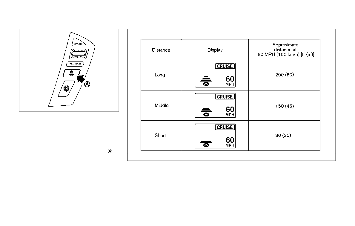
SSD0967
How to change set distance to
vehicle ahead
The distance to the vehicle ahead can be
selected at any time depending on the
traffic conditions.
Each time the DISTANCE switch
is
pushed, the set distance will change to
long, middle, short and back to long again
in that sequence.
JVS0732X
. The distance to the vehicle ahead will
change according to the vehicle
speed. The higher the vehicle speed,
the longer the distance.
. If the engine is stopped, the set
distance becomes “long”. (Each time
the engine is started, the initial setting
becomes “long”.)
Approach warning
If your vehicle comes closer to the vehicle
ahead due to rapid deceleration of that
vehicle or if another vehicle cuts in, the
system warns the driver with the chime
and ICC system display. Decelerate by
depressing the brake pedal to maintain a
Starting and driving 5-73

5-74 Starting and driving
safe vehicle distance if:
. The chime sounds.
. The vehicle ahead detection and set
distance indicator blink.
The warning chime may not sound in
some cases when there is a short dis-
tance between vehicles. Some examples
are:
. When the vehicles are traveling at the
same speed and the distance be-
tween vehicles is not changing
. When the vehicle ahead is traveling
faster and the distance between ve-
hicles is increasing
. When a vehicle cuts in near your
vehicle
The warning chime will not sound when:
. Your vehicle approaches other vehi-
cles that are parked or moving slowly.
. The accelerator pedal is depressed,
overriding the system.
NOTE:
The approach warning chime may
sound and the system display may
blink when the radar sensor detects
objects on the side of the vehicle or on
the side of the road. This may cause the
ICC system to decelerate or accelerate
the vehicle. The radar sensor may de-
tect these objects when the vehicle is
driven on winding roads, narrow roads,
hilly roads or when entering or exiting a
curve. In these cases you will have to
manually control the proper distance
ahead of your vehicle.
Also, the sensor sensitivity can be af-
fected by vehicle operation (steering
maneuver or driving position in the lane)
or traffic or vehicle condition (for example,
if a vehicle is being driven with some
damage).
Automatic cancellation
A chime sounds under the following
conditions and the control is automati-
cally canceled.
. When the vehicle ahead is not de-
tected and your vehicle is traveling
below the speed of 15 MPH (24 km/h)
. When the system judges the vehicle is
at standstill
. When the shift lever is not in the D
(Drive) or manual shift mode
. When the parking brake is applied
. When the SNOW mode switch is
pushed on.
. When the 4WD shift switch is in the 4H
or 4L position (for 4WD models)
. When the VDC system is turned off
. When ABS or VDC (including the trac-
tion control system) operates
. When distance measurement be-
comes impaired due to adhesion of
dirt or obstruction to the sensor
. When a wheel slips
. When the radar signal is temporarily
interrupted
Vehicle-to-vehicle distance control
mode limitations
WARNING
Listed below are the system limita-
tions for the ICC system. Failure to
operate the vehicle in accordance
with these system limitations could
result in serious injury or death.
. The system is primarily intended
for use on straight, dry, open
roads with light traffic. It is not
advisable to use the system in
city traffic or congested areas.
. This system will not adapt auto-
matically to road conditions. This
system should be used in evenly
flowing traffic. Do not use the
system on roads with sharp
curves, or on icy roads, in heavy
rain or in fog.

. As there is a performance limit to
the distance control function,
never rely solely on the ICC sys-
tem. This system does not correct
careless, inattentive or absent-
minded driving, or overcome
poor visibility in rain, fog, or other
bad weather. Decelerate the ve-
hicle speed by depressing the
brake pedal, depending on the
distance to the vehicle ahead
and the surrounding circum-
stances in order to maintain a
safe distance between vehicles.
. If the vehicle ahead comes to a
stop, the vehicle decelerates to a
standstill within the limitations of
the system. The system will can-
cel once it judges that the vehicle
has come to a standstill and
sound a warning chime. To pre-
vent the vehicle from moving, the
driver must depress the brake
pedal.
. Always pay attention to the op-
eration of the vehicle and be
ready to manually control the
proper following distance. The
vehicle-to-vehicle distance con-
trol mode of the ICC system may
not be able to maintain the se-
lected distance between vehicles
(following distance) or selected
vehicle speed under some cir-
cumstances.
. The system may not detect the
vehicle in front of you in certain
road or weather conditions. To
avoid accidents, never use the ICC
system under the following con-
ditions:
— On roads where the traffic is
heavy or there are sharp
curves
— On slippery road surfaces
such as on ice or snow, etc.
— During bad weather (rain, fog,
snow, etc.)
— When rain, snow or dirt adhere
to the system sensor
— On steep downhill roads (the
vehicle may go beyond the set
vehicle speed and frequent
braking may result in over-
heating the brakes)
— On repeated uphill and down-
hill roads
— When traffic conditions make
it difficult to keep a proper
distance between vehicles be-
cause of frequent accelera-
tion or deceleration
. Do not use the ICC system if you
are towing a trailer. The system
may not detect a vehicle ahead.
. In some road or traffic conditions,
a vehicle or object can unexpect-
edly come into the sensor detec-
tion zone and cause automatic
braking. You may need to control
the distance from other vehicles
using the accelerator pedal. Al-
ways stay alert and avoid using
the ICC system when it is not
recommended in this section.
The radar sensor will not detect the
following objects:
. Stationary and slow moving vehicles
. Pedestrians or objects in the roadway
. Oncoming vehicles in the same lane
. Motorcycles traveling offset in the
travel lane
The sensor generally detects the signals
returned from the vehicle ahead. There-
fore, if the sensor cannot detect the
reflection from the vehicle ahead, the
ICC system may not maintain the se-
lected distance.
The following are some conditions in
which the sensor cannot detect the
Starting and driving 5-75
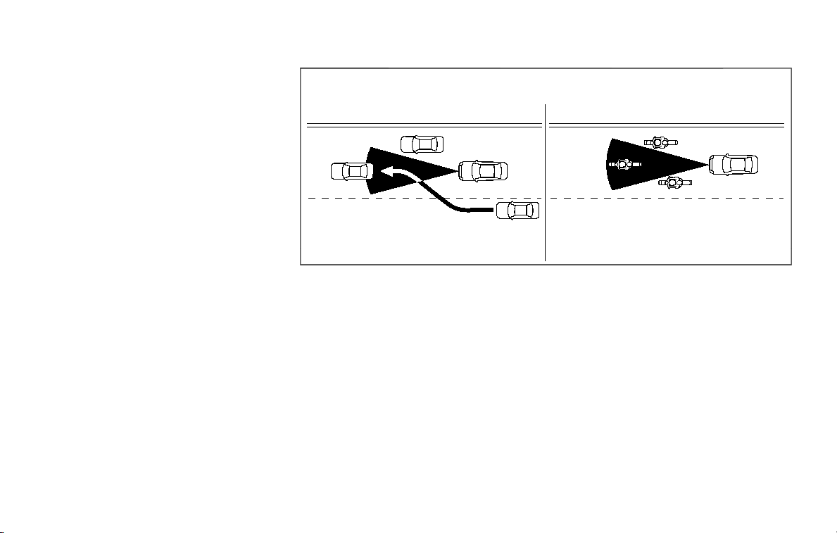
5-76 Starting and driving
signals:
. When the snow or road spray from
traveling vehicles reduces the sensor’s
visibility
. When excessively heavy baggage is
loaded in the rear seat or the luggage
area of your vehicle
. When your vehicle is towing a trailer,
etc.
The ICC system is designed to automati-
cally check the sensor’s operation within
the limitation of the system. When the
sensor is covered with dirt or is ob-
structed, the system will automatically
be canceled. If the sensor is covered with
ice, a transparent or translucent vinyl bag,
etc., the ICC system may not detect them.
In these instances, the vehicle-to-vehicle
distance control mode may not cancel
and may not be able to maintain the
selected following distance from the ve-
hicle ahead. Be sure to check and clean
the sensor regularly.
SSD0252
The detection zone of the ICC sensor is
limited. A vehicle ahead must be in the
detection zone for the vehicle-to-vehicle
distance detection mode to maintain the
selected distance from the vehicle ahead.
A vehicle ahead may move outside of the
detection zone due to its position within
the same lane of travel. Motorcycles may
not be detected in the same lane ahead if
they are traveling offset from the center-
line of the lane. A vehicle that is entering
the lane ahead may not be detected until
the vehicle has completely moved into
the lane. If this occurs, the ICC system
may warn you by blinking the system
indicator and sounding the chime. The
driver may have to manually control the
proper distance away from vehicle tra-
veling ahead.

SSD0253
When driving on some roads, such as
winding, hilly, curved, narrow roads, or
roads which are under construction, the
ICC sensor may detect vehicles in a
different lane, or may temporarily not
detect a vehicle traveling ahead. This
may cause the ICC system to decelerate
or accelerate the vehicle.
The detection of vehicles may also be
affected by vehicle operation (steering
maneuver or traveling position in the
lane, etc.) or vehicle condition. If this
occurs, the ICC system may warn you
by blinking the system indicator and
sounding the chime unexpectedly. You
will have to manually control the proper
distance away from the vehicle travel-
ing ahead.
Starting and driving 5-77
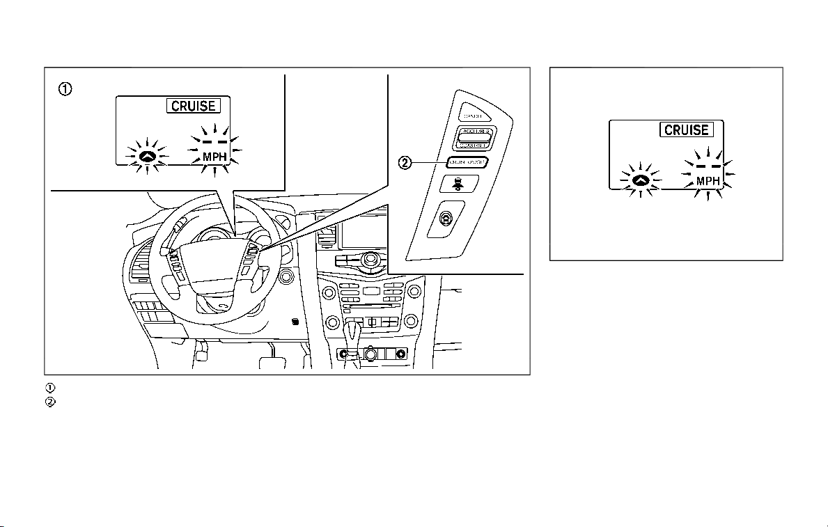
5-78 Starting and driving
JVS0889X
Warning light and display (example)
MAIN (ON·OFF) switch
SSD1110
System temporarily unavailable
Condition A:
Under the following conditions, the ICC
system is automatically canceled. The
chime will sound and the system will not
be able to be set.
. When the VDC is turned off
. When the ABS or VDC operates
. When a tire slips
. When the SNOW mode switch is
pushed on
. When the 4WD shift switch is in the 4H
or 4L position (for 4WD models)
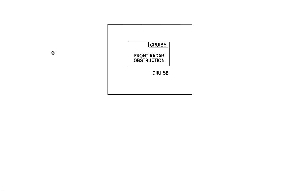
. When the radar signal is temporarily
interrupted
Action to take:
When the conditions listed above are no
longer present, turn the system off using
the MAIN switch
. Turn the ICC system
back on to use the system.
JVS0481X
Condition B:
Under the following conditions, making it
impossible to detect a vehicle ahead, the
ICC system is automatically canceled.
The chime will sound, the ICC system
warning light (orange) will come on and
the “FRONT RADAR OBSTRUCTION” warn-
ing message will appear in the vehicle
information display.
. When the radar sensor area of the
front bumper is covered with dirt or is
obstructed
Action to take:
If the warning light (orange) comes on or
warning message appears, stop the ve-
hicle in a safe place, place the shift lever in
the P (Park) position and turn the engine
off. When the radar signal is temporarily
interrupted, clean the sensor area of the
front bumper and restart the engine. If
the warning light (orange) stays on or
warning message continues to be dis-
played, have the ICC system checked. It is
recommended you visit a NISSAN dealer
for this service.
. When driving on roads with limited
road structures or buildings (for ex-
ample, long bridges, deserts, snow
fields, driving next to long walls)
Action to take:
When the above conditions no longer
exist, the ICC system will resume auto-
matically.
Starting and driving 5-79
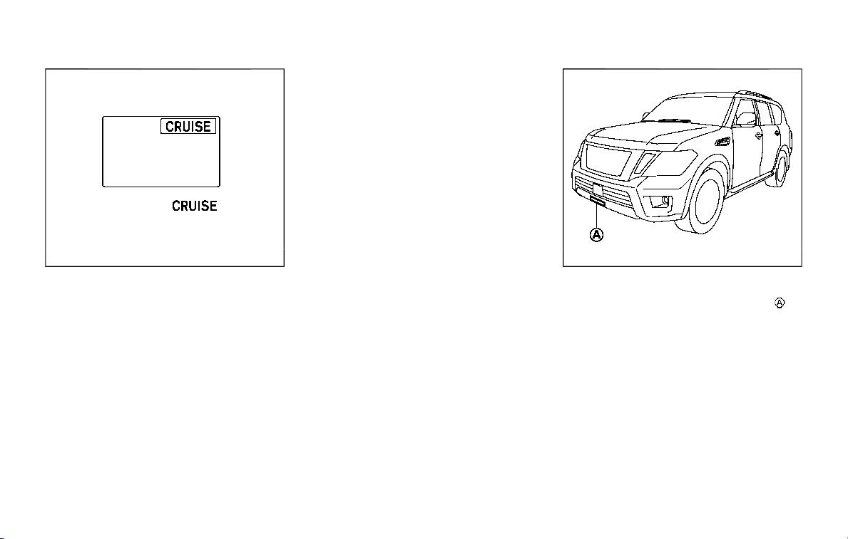
5-80 Starting and driving
SSD0979
Condition C:
When the ICC system is not operating
properly, the chime sounds and the ICC
system warning light (orange) will come
on.
Action to take:
If the warning light comes on, park the
vehicle in a safe place. Turn the engine off,
restart the engine, resume driving and set
the ICC system again.
If it is not possible to set the system or
the indicator stays on, it may indicate
that the ICC system is malfunctioning.
Although the vehicle is still driveable
under normal conditions, have the ve-
hicle checked. It is recommended you
visit a NISSAN dealer for this service.
JVS0913X
System maintenance
The sensor for the ICC system is
located below the front bumper.
To keep the ICC system operating prop-
erly, be sure to observe the following:
. Always keep the sensor area of the
front bumper clean.
. Do not strike or damage the areas
around the sensor.
. Do not cover or attach stickers or
similar objects on the front bumper
near the sensor area. This could cause
failure or malfunction.
. Do not attach metallic objects near
the sensor area (brush guard, etc.).

This could cause failure or malfunc-
tion.
. Do not alter, remove or paint the front
bumper. It is recommended you con-
tact a NISSAN dealer before customiz-
ing or restoring the front bumper.
FCC Notice:
For USA:
This device complies with Part 15 of the
FCC Rules. Operation is subject to the
following two conditions:
1. This device may not cause harmful
interference, and
2. This device must accept any inter-
ference received, including interfer-
ence that may cause undesired
operation.
FCC Warning
Changes or modification not expressly
approved by the party responsible for
compliance could void the user’s
authority to operate the equipment.
For Canada:
This device complies with Industry Ca-
nada licence-exempt RSS standard(s).
Operation is subject to the following
two conditions:
1. This device may not cause interfer-
ence, and
2. This device must accept any inter-
ference, including interference that
may cause undesired operation of
the device.
CONVENTIONAL (fixed speed)
CRUISE CONTROL MODE
This mode allows driving at a speed
between 25 to 90 MPH (40 to 144 km/h)
without keeping your foot on the accel-
erator pedal.
WARNING
. In the conventional (fixed speed)
cruise control mode, a warning
chime does not sound to warn
you if you are too close to the
vehicle ahead, as neither the pre-
sence of the vehicle ahead nor
the vehicle-to-vehicle distance is
detected.
. Pay special attention to the dis-
tance between your vehicle and
the vehicle ahead of you or a
collision could occur.
. Always confirm the setting in the
ICC system display.
. Do not use the conventional
(fixed speed) cruise control mode
when driving under the following
conditions.
— when it is not possible to keep
the vehicle at a set speed
— in heavy traffic or in traffic
that varies in speed
— on winding or hilly roads
— on slippery roads (rain, snow,
ice, etc.)
— in very windy areas
Doing so could cause a loss of
vehicle control and result in an acci-
dent.
Starting and driving 5-81
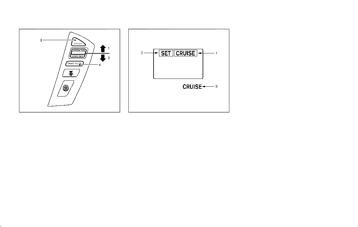
5-82 Starting and driving
SSD0968
Conventional (fixed speed) cruise
control switch
1. ACCELERATE/RESUME switch:
Resumes set speed or increases speed
incrementally.
2. COAST/SET switch:
Sets the desired cruise speed, reduces
speed incrementally.
3. CANCEL switch:
Deactivates the system without eras-
ing the set speed.
4. MAIN switch:
Master switch to activate the system.
SSD1013
Conventional (fixed speed) cruise
control mode display and indica-
tors
The display is on the vehicle information
display located between the speed-
ometer and tachometer.
1. MAIN switch indicator:
Indicates that the MAIN switch is ON.
2. Cruise set switch indicator:
Displays while the vehicle speed is
controlled by the conventional (fixed
speed) cruise control mode of the ICC
system.
3. Cruise system warning light:
Comes on if there is a malfunction in
the cruise control system.
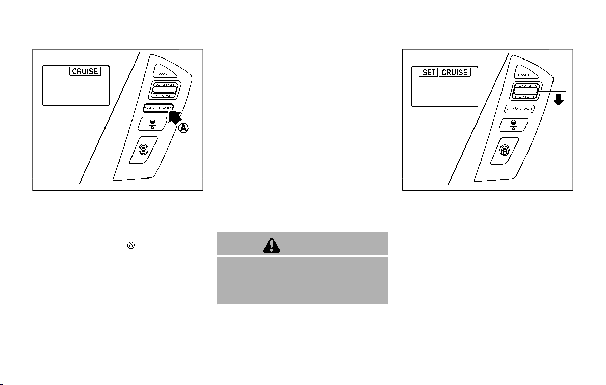
SSD0969
Operating conventional (fixed
speed) cruise control mode
To turn on the conventional (fixed
speed) cruise control mode, push and
hold the MAIN switch
for longer than
about 1.5 seconds.
When pushing the MAIN switch on, the
conventional (fixed speed) cruise control
mode display and the MAIN switch indi-
cator are displayed on the vehicle infor-
mation display. After you hold the MAIN
switch on for longer than about 1.5
seconds, the ICC system display goes
out. The MAIN switch indicator stays lit.
You can now set your desired cruising
speed. Pushing the MAIN switch again will
turn the system completely off.
When the ignition switch is pushed to the
OFF position, the system is also automa-
tically turned off.
To use the ICC system again, quickly push
and release the MAIN switch (vehicle-to-
vehicle distance control mode) or push
and hold it (conventional cruise control
mode) again to turn it on.
When the Intelligent Distance Control (I-
DC) system is on, the conventional (fixed
speed) cruise control mode cannot be
turned on even though the MAIN switch is
pushed and held.
To turn on the conventional (fixed speed)
cruise control mode, turn off the I-DC
system. See “Intelligent Distance Control
(I-DC)” (P.5-85).
CAUTION
To avoid accidentally engaging
cruise control, make sure to turn
the MAIN switch off when not using
the ICC system.
SSD0970
To set cruising speed, accelerate your
vehicle to the desired speed, push the
COAST/SET switch and release it. (The
SET indicator will come on in the display.)
Take your foot off the accelerator pedal.
Your vehicle will maintain the set speed.
. To pass another vehicle, depress the
accelerator pedal. When you release
the pedal, the vehicle will return to the
previously set speed.
. The vehicle may not maintain the set
speed when going up or down steep
hills. If this happens, manually main-
tain vehicle speed.
To cancel the preset speed, use any of
the following methods:
Starting and driving 5-83
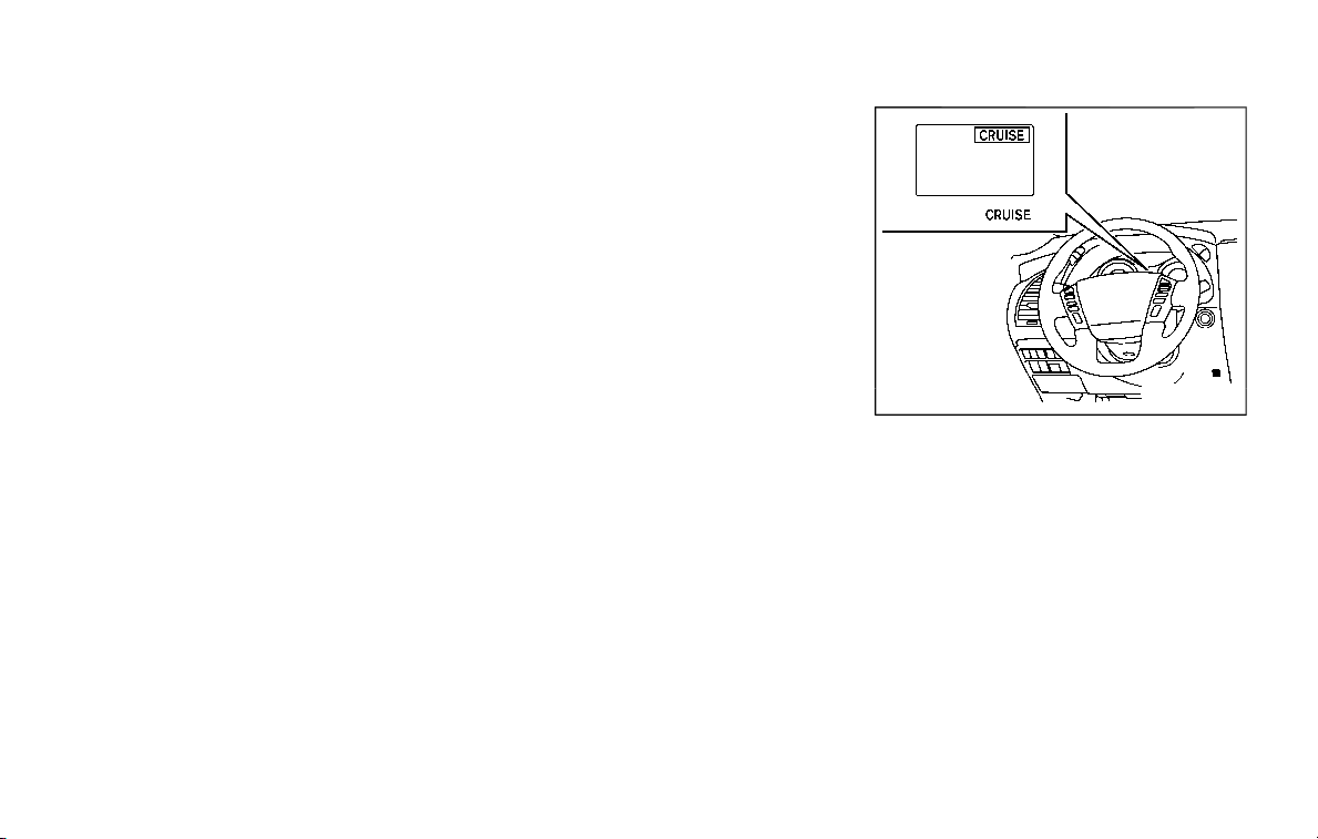
5-84 Starting and driving
1. Push the CANCEL switch. The SET
indicator will turn off.
2. Tap the brake pedal. The SET indicator
will turn off.
3. Turn the MAIN switch off. Both the
MAIN switch indicator and SET indica-
tor will turn off.
To reset at a faster cruising speed, use
one of the following three methods:
1. Depress the accelerator pedal. When
the vehicle attains the desired speed,
push and release the COAST/SET
switch.
2. Push and hold the ACCELERATE/RE-
SUME set switch. When the vehicle
attains the speed you desire, release
the switch.
3. Push, then quickly release the ACCEL-
ERATE/RESUME switch. Each time you
do this, the set speed will increase by
about 1 MPH (1.6 km/h).
To reset at a slower cruising speed, use
one of the following three methods:
1. Lightly tap the brake pedal. When the
vehicle attains the desired speed,
push the COAST/SET switch and re-
lease it.
2. Push and hold the COAST/SET switch.
Release the switch when the vehicle
slows down to the desired speed.
3. Push, then quickly release the COAST/
SET switch. Each time you do this, the
set speed will decrease by about 1
MPH (1.6 km/h).
To resume the preset speed, push and
release the ACCELERATE/RESUME switch.
The vehicle will resume the last set
cruising speed when the vehicle speed is
over 25 MPH (40 km/h).
System temporarily unavailable
Under the following condition, a chime
will sound and the system control is
automatically canceled.
. When the vehicle slows down more
than 8 MPH (13 km/h) below the set
speed
. When the shift lever is shifted to the N
(Neutral) position
. When the parking brake is applied
. When the VDC (including the traction
control system) operates.
. When a wheel slips
JVS0661X
Warning light
When the system is not operating prop-
erly, the chime sounds and the system
warning light (orange) will come on.
Action to take:
If the warning light comes on, park the
vehicle in a safe place. Turn the engine off,
restart the engine, resume driving and
then perform the setting again.
If it is not possible to set or the indicator
stays on, it may indicate that the
system is malfunctioning. Although the
vehicle is still driveable under normal
conditions, have the vehicle checked. It
is recommended you visit a NISSAN

dealer for this service.
WARNING
Failure to follow the warnings and
instructions for proper use of the I-
DC system could result in serious
personal injury or death.
. Always drive carefully and atten-
tively when using the I-DC sys-
tem. Read and understand the
Owner’s Manual thoroughly be-
fore using the I-DC system. To
avoid serious injury or death, do
not rely on the system to prevent
accidents or to control the vehi-
cle’s speed in emergency situa-
tions. Do not use the I-DC system
except in appropriate road and
traffic conditions.
. This system is only an aid to
assist the driver and is not a
collision warning or avoidance
device. It is the driver’s responsi-
bility to stay alert, drive safely
and be in control of the vehicle at
all times.
. As there is a performance limit to
the distance control function,
never rely solely on the I-DC
system. This system does not
correct careless, inattentive or
absent-minded driving, or over-
come poor visibility in rain, fog, or
other bad weather. Decelerate
the vehicle speed by depressing
the brake pedal, depending on
the distance to the vehicle ahead
and the surrounding circum-
stances in order to maintain a
safe distance between vehicles.
. Always pay attention to the op-
eration of the vehicle and be
ready to manually decelerate to
maintain the proper following
distance. The I-DC system may
not be able to decelerate the
vehicle under some circum-
stances.
. This system only brakes and
moves the accelerator pedal up-
ward to help assist the driver to
maintain a following distance
from the vehicle ahead. Accelera-
tion should be operated by the
driver.
. The I-DC system does not control
vehicle speed or warn you when
you approach stationary and
slow moving vehicles. You must
pay attention to vehicle operation
to maintain proper distance from
vehicles ahead.
Starting and driving 5-85
INTELLIGENT DISTANCE CONTROL
(I-DC) (if so equipped)
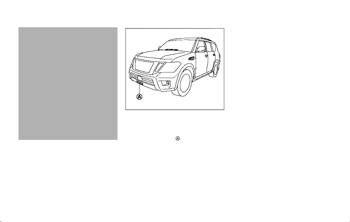
5-86 Starting and driving
. The I-DC system automatically
decelerates your vehicle to help
assist the driver to maintain a
following distance from the vehi-
cle ahead. Manually brake when
deceleration is required to main-
tain a safe distance upon sudden
braking by the vehicle ahead or
when a vehicle suddenly appears
in front of you. Always stay alert
when using the I-DC system.
. If the vehicle ahead comes to a
stop, the vehicle decelerates to a
standstill within the limitations of
the system. The system will can-
cel with a warning chime once it
judges that the vehicle has come
to a standstill. To prevent the
vehicle from moving, the driver
must depress the brake pedal.
JVS0913X
The system is intended to assist the driver
to keep a following distance from the
vehicle ahead traveling in the same lane
and direction.
If the radar sensor
detects a slower
moving vehicle ahead, the system will
reduce the vehicle speed to help assist
the driver to maintain a following dis-
tance.
The system automatically controls the
throttle and applies the brakes (up to
approximately 40% of vehicle braking
power) if necessary.
The detection range of the sensor is
approximately 650 ft (200 m) ahead.
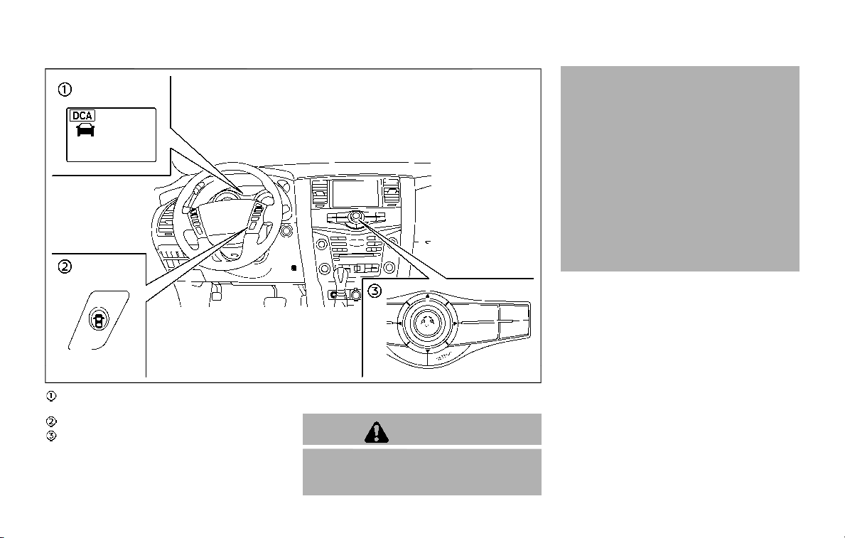
JVS1100X
Indicators (on the vehicle information
display)
Dynamic driver assistance switch
Center multi-function control panel
I-DC SYSTEM OPERATION
WARNING
Failure to follow the warnings and
instructions for proper use of the I-
DC system could result in serious
personal injury or death.
. When the vehicle ahead detection
indicator light is not illuminated,
system will not control the vehi-
cle or warn the driver.
. Never place your foot under the
brake pedal. Your foot may be
caught when the system controls
the brake.
. Depending on the position of the
accelerator pedal, the system
may not be able to assist the
driver to release the accelerator
pedal appropriately.
The I-DC system brakes and moves the
accelerator pedal upward according to
the distance from and the relative speed
of the vehicle ahead to help assist the
driver in maintaining a following distance.
The system will decelerate as necessary
and if the vehicle ahead comes to a stop,
the vehicle decelerates to a standstill.
However, the I-DC system can only apply
up to approximately 40% of the vehicle’s
total braking power. If a vehicle moves
into the traveling lane ahead or if a
vehicle traveling ahead rapidly decele-
rates, the distance between vehicles
may become closer because the I-DC
system cannot decelerate the vehicle
Starting and driving 5-87
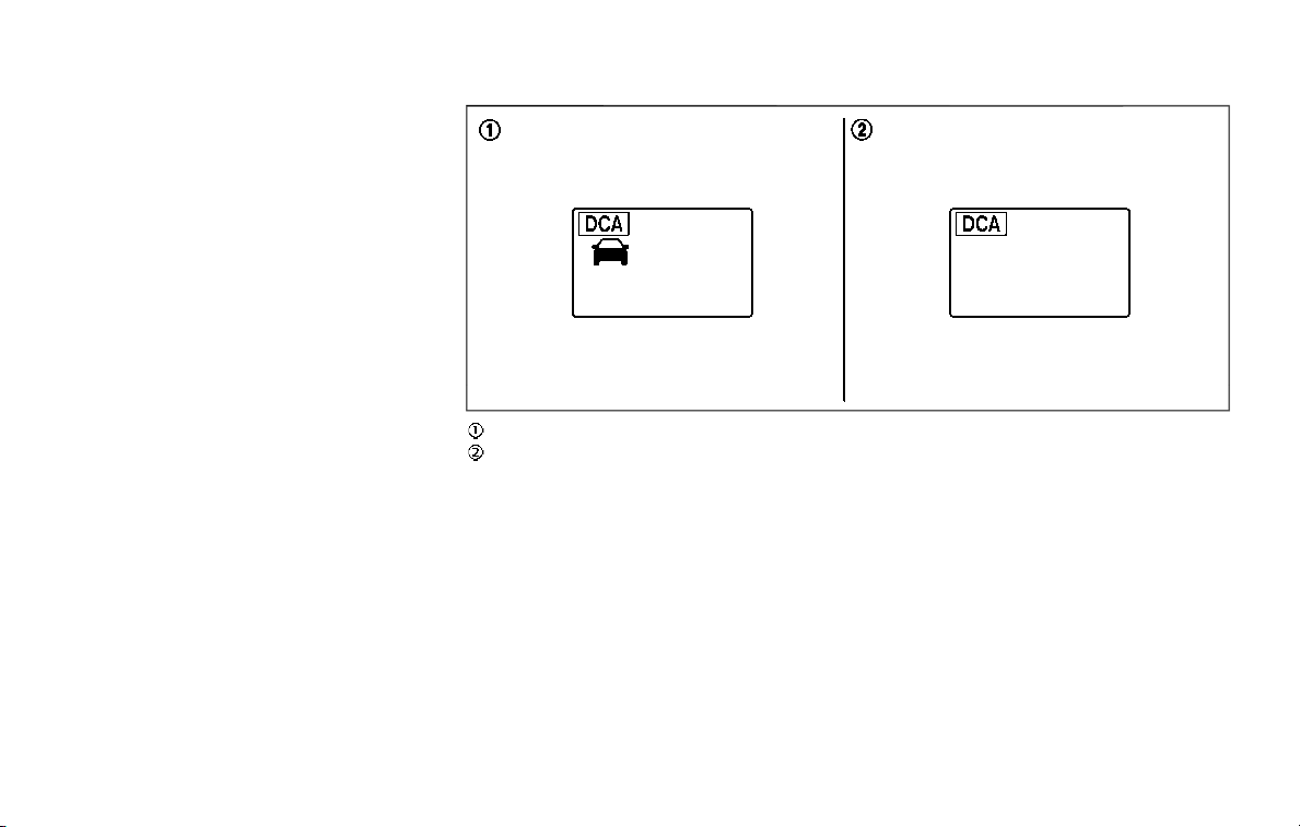
5-88 Starting and driving
quickly enough. If this occurs, the I-DC
system will sound a warning chime and
blink the system display to notify the
driver to take necessary action.
See “Approach warning” (P.5-89).
SSD0997
System set display with a vehicle ahead
System set display without a vehicle
ahead
The I-DC system helps assist the driver to
keep a following distance to the vehicle
ahead by braking and moving the accel-
erator pedal upward in the normal driving
condition.
When a vehicle ahead is detected:
The vehicle ahead detection indicator
comes on.
When the vehicle approaches a vehicle
ahead:
. If the driver’s foot is not on the
accelerator pedal, the system acti-
vates the brakes to decelerate
smoothly as necessary. If the vehicle
ahead comes to a stop, the vehicle
decelerates to a standstill within the
limitations of the system.
. If the driver’s foot is on the accelerator
pedal, the system moves the accel-
erator pedal upward to assist the
driver to release the accelerator pedal.
When brake operation by the driver is
required:
The system alerts the driver by a warning
chime and blinking the vehicle ahead
detection indicator. If the driver’s foot is
on the accelerator pedal after the warn-
ing, the system moves the accelerator
pedal upward to assist the driver to

switch to the brake pedal.
NOTE:
. The stop lights of the vehicle come
on when braking is performed by
the I-DC system.
. When the brake operates, a noise
may be heard and/or vibration may
be felt. This is not a malfunction.
Overriding the system:
The following driver’s operation overrides
the system operation.
. When the driver depresses the accel-
erator pedal even further while the
system is moving the accelerator
pedal upward, the I-DC system control
of the accelerator pedal is canceled.
. When the driver’s foot is on the accel-
erator pedal, the brake control by the
system is not operated.
. When the driver’s foot is on the brake
pedal, neither the brake control nor
the alert by the system operates.
. When the Intelligent Cruise Control
(ICC) system is set, the I-DC system
will be inactive.
Approach warning
If your vehicle comes closer to the vehicle
ahead due to rapid deceleration of that
vehicle or if another vehicle cuts in, the
system warns the driver with the chime
and I-DC system display. Decelerate by
depressing the brake pedal to maintain a
safe vehicle distance if:
. The chime sounds.
. The vehicle ahead detection indicator
blinks.
The warning chime may not sound in
some cases when there is a short dis-
tance between vehicles. Some examples
are:
. When the vehicles are traveling at the
same speed and the distance be-
tween vehicles is not changing
. When the vehicle ahead is traveling
faster and the distance between ve-
hicles is increasing
. When a vehicle cuts in near your
vehicle
The warning chime will not sound when
your vehicle approaches vehicles that are
parked or moving slowly.
NOTE:
The approach warning chime may
sound and the system display may
blink when the radar sensor detects
objects on the side of the vehicle or on
the side of the road. This may cause the
I-DC system to decelerate or accelerate
the vehicle. The radar sensor may de-
tect these objects when the vehicle is
driven on winding roads, narrow roads,
hilly roads or when entering or exiting a
curve. In these cases you will have to
manually control the proper distance
ahead of your vehicle.
Also, the sensor sensitivity can be af-
fected by vehicle operation (steering
maneuver or driving position in the lane)
or traffic or vehicle condition (for example,
if a vehicle is being driven with some
damage).
Starting and driving 5-89
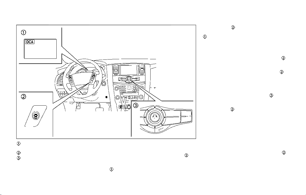
5-90 Starting and driving
JVS1101X
I-DC system switch indicator (on the
vehicle information display)
Dynamic driver assistance switch
Center multi-function control panel
TURNING THE I-DC SYSTEM ON/OFF
To turn on the I-DC system, push the
dynamic driver assistance switch
on
the steering wheel after starting the
engine. The I-DC system switch indicator
in the vehicle information display will
appear. Push the dynamic driver assis-
tance switch
again to turn off the I-DC
system. The I-DC system switch indicator
will turn off.
The system will start to operate after the
vehicle speed is above approximately 3
MPH (5 km/h).
The dynamic driver assistance switch
is
used for the I-DC, I-LI (if so equipped) and
I-BSI (if so equipped) systems. When the
dynamic driver assistance switch
is
pushed, the I-LI and I-BSI systems will
also turn on or off simultaneously. The I-
DC system can be individually set to on or
off on the center display using the center
multi-function control panel
. If the
system is set to off, the system will not
turn on even if the dynamic driver assis-
tance switch
is pushed to on. To set the
system to on or off on the center display,
see “How to enable/disable the I-DC
system” (P.5-91).
When the conventional (fixed speed)
cruise control mode is operating, the I-
DC system will not operate. (To use the I-
DC system, turn the conventional (fixed
speed) cruise control mode off, then push
the dynamic driver assistance switch
.)
For details about the conventional (fixed
speed) cruise control mode, see “Intelli-
gent Cruise Control (ICC)” (P.5-63).
When the engine is turned off, the system
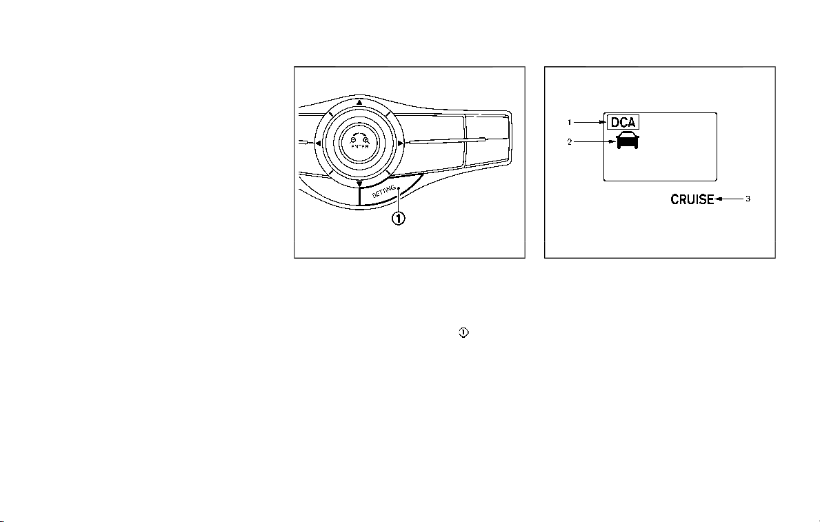
is automatically turned off.
JVS1043X
HOW TO ENABLE/DISABLE THE I-DC
SYSTEM
Perform the following steps to enable or
disable the I-DC system.
1. Push the SETTING button
.
2. Touch [Driver Assistance].
3. Touch [Forward Assist].
4. Touch [Distance Control Assist] to turn
the system ON/OFF.
SSD0994
I-DC SYSTEM DISPLAY AND INDICA-
TORS
The display is located between the speed-
ometer and tachometer.
1. I-DC system switch indicator:
Indicates that the dynamic driver
assistance switch is ON.
2. Vehicle ahead detection indicator:
Indicates whether it detects a vehicle
in front of you.
3. I-DC system warning light (orange):
The light comes on if there is a
malfunction in the I-DC system.
Starting and driving 5-91

5-92 Starting and driving
I-DC SYSTEM LIMITATIONS
WARNING
Listed below are the system limita-
tions of the I-DC system. Failure to
operate the vehicle in accordance
with these system limitations could
result in serious injury or death.
. This system will not adapt auto-
matically to road conditions. Do
not use the system on roads with
sharp curves, or on icy roads, in
heavy rain or in fog.
. The I-DC system will not apply
brake control while the driver’s
foot is on the accelerator pedal.
. As there is a performance limit to
the distance control function,
never rely solely on the I-DC
system. This system does not
correct careless, inattentive or
absent-minded driving, or over-
come poor visibility in rain, fog, or
other bad weather. Decelerate
the vehicle speed by depressing
the brake pedal, depending on
the distance to the vehicle ahead
and the surrounding circum-
stances in order to maintain a
safe distance between vehicles.
. The system may not detect the
vehicle in front of you in certain
road or weather conditions. To
avoid accidents, never use the I-
DC system under the following
conditions:
— On roads with sharp curves
— On slippery road surfaces
such as on ice or snow, etc.
— On off-road surfaces such as
on sand or rock, etc.
— During bad weather (rain, fog,
snow, etc.)
— When rain, snow or dirt adhere
to the system sensor
— On steep downhill roads (fre-
quent braking may result in
overheating the brakes)
— On repeated uphill and down-
hill roads
— When towing a trailer or other
vehicle
. In some road or traffic conditions,
a vehicle or object can unexpect-
edly come into the sensor detec-
tion zone and cause automatic
braking. You may need to control
the distance from other vehicles
using the accelerator pedal. Al-
ways stay alert and avoid using
the I-DC system when it is not
recommended in this section.
The radar sensor will not detect the
following objects:
. Stationary and slow moving vehicles
. Pedestrians or objects in the roadway
. Oncoming vehicles in the same lane
. Motorcycles traveling offset in the
travel lane
The following are some conditions in
which the sensor cannot detect the
signals:
. When the snow or road spray from
traveling vehicles reduces the sensor’s
visibility
. When excessively heavy baggage is
loaded in the rear seat or the luggage
room of your vehicle
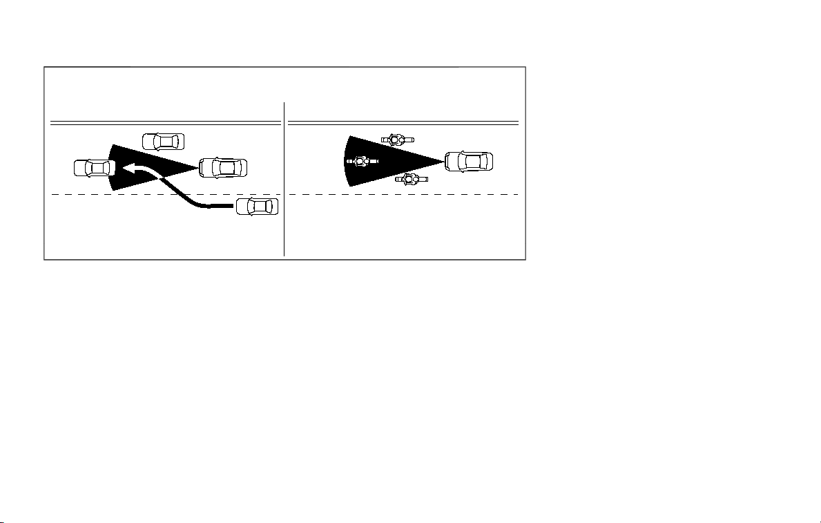
SSD0252
The detection zone of the sensor is
limited. A vehicle ahead must be in the
detection zone for the system to operate.
A vehicle ahead may move outside of the
detection zone due to its position within
the same lane of travel. Motorcycles may
not be detected in the same lane ahead if
they are traveling offset from the center-
line of the lane. A vehicle that is entering
the lane ahead may not be detected until
the vehicle has completely moved into
the lane. If this occurs, the system may
warn you by blinking the system indi-
cator and sounding the chime. The
driver may have to manually control
the proper distance away from vehicle
traveling ahead.
Starting and driving 5-93
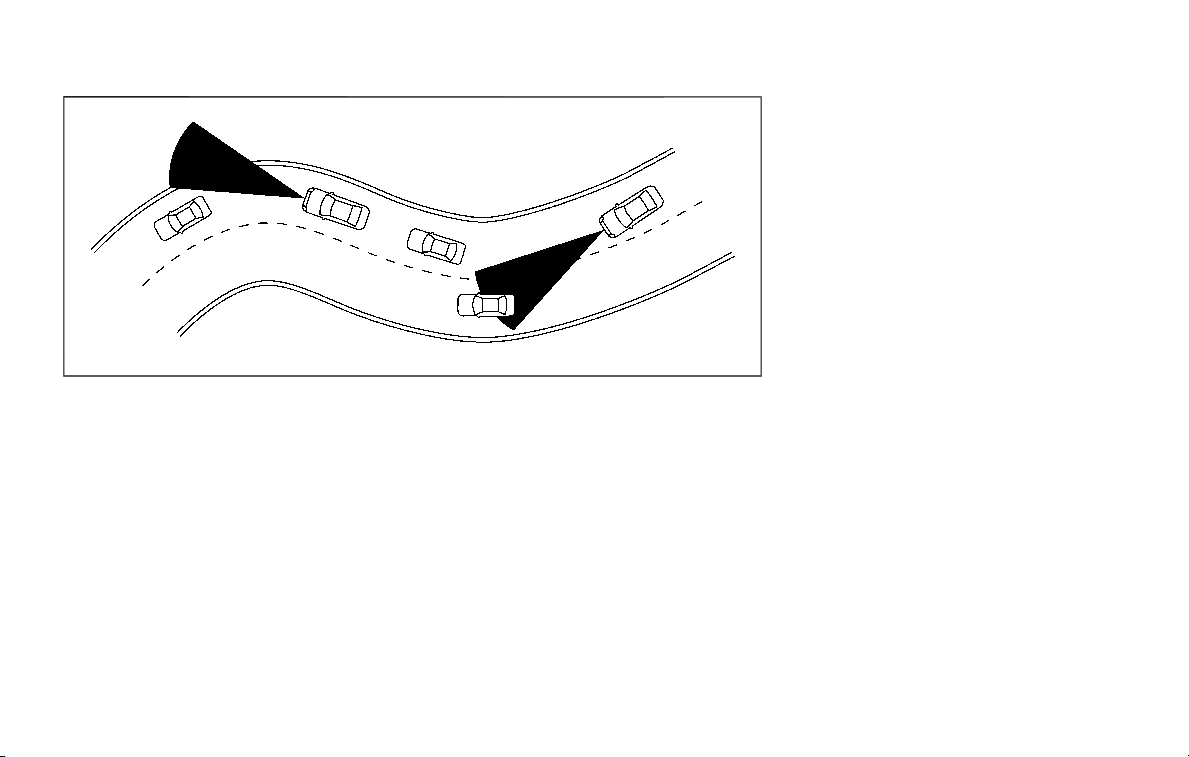
5-94 Starting and driving
SSD0253
When driving on some roads, such as
winding, hilly, curved, narrow roads, or
roads which are under construction, the
sensor may detect vehicles in a different
lane, or may temporarily not detect a
vehicle traveling ahead. This may cause
the system to work inappropriately.
The detection of vehicles may also be
affected by vehicle operation (steering
maneuver or traveling position in the
lane, etc.) or vehicle condition. If this
occurs, the system may warn you by
blinking the system indicator and
sounding the chime unexpectedly. You
will have to manually control the proper
distance away from the vehicle travel-
ing ahead.
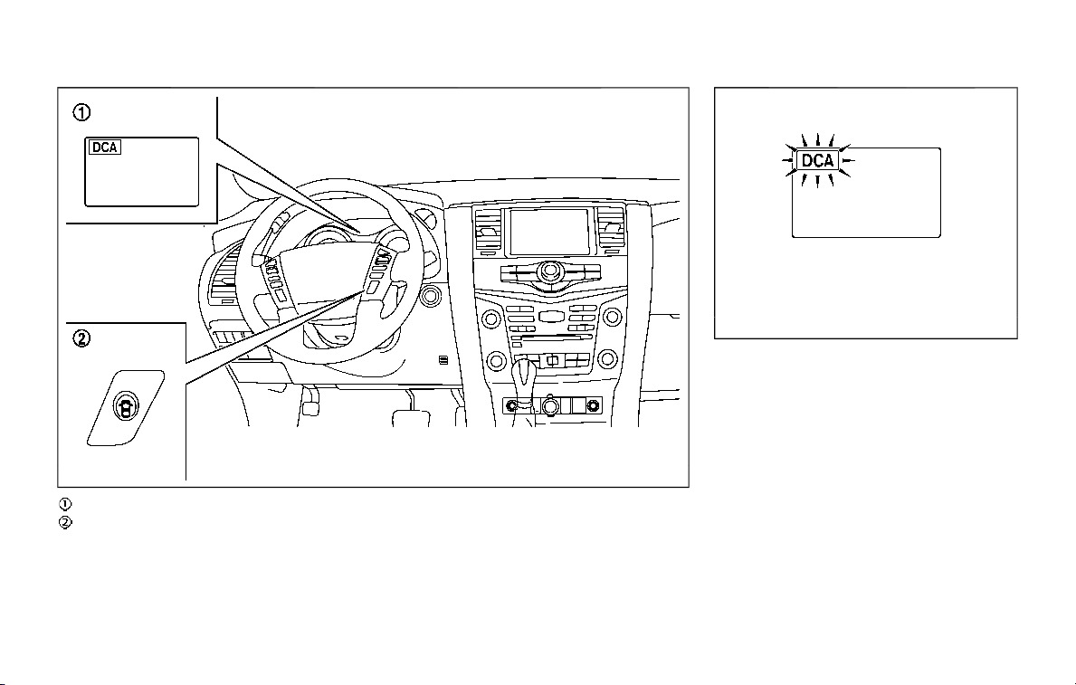
JVS0892X
Warning light and indicators
Dynamic driver assistance switch
SSD0996
SYSTEM TEMPORARILY UNAVAIL-
ABLE
Condition A:
Under the following conditions, the I-DC
system is automatically canceled. The
chime will sound and the I-DC system
switch indicator will blink. The system will
not be able to be set.
. When the VDC system is off (To use
the I-DC system, turn on the VDC, then
push the dynamic driver assistance
switch.)
For details about the VDC system, see
“Vehicle Dynamic Control (VDC) sys-
tem” (P.5-133).
Starting and driving 5-95

5-96 Starting and driving
. When the VDC or ABS (including the
traction control system) operates
. When the SNOW mode switch is ON
(To use the I-DC system, turn off the
SNOW mode switch, then turn on the
dynamic driver assistance switch
.)
For details about the SNOW mode
switch, see “SNOW mode switch” (P.2-
46).
. When the 4WD shift switch is in the 4H
or 4L position (for 4WD models)
. When the radar signal is temporarily
interrupted
Action to take:
When the conditions listed above are no
longer present, turn the system off with
the dynamic driver assistance switch
.
Turn the I-DC system back on to use the
system.
JVS0482X
Condition B:
Under the following conditions, making it
impossible to detect a vehicle ahead, the
I-DC system is automatically canceled.
The chime will sound, the I-DC system
warning light (orange) will come on and
the “FRONT RADAR OBSTRUCTION” warn-
ing message will appear in the vehicle
information display.
. When the radar sensor area of the
front bumper is covered with dirt or is
obstructed
Action to take:
If the I-DC system warning light (orange)
comes on and the warning message
appears, stop the vehicle in a safe place,
place the shift lever in the P (Park)
position and turn the engine off. When
the radar signal is temporarily inter-
rupted, clean the sensor area of the front
bumper and restart the engine. If the
warning message continues to be dis-
played, have the I-DC system checked. It is
recommended you visit a NISSAN dealer
for this service.
. When driving on roads with limited
road structures or buildings (for ex-
ample, long bridges, deserts, snow
fields, driving next to long walls)
Action to take:
When the above conditions no longer
exist, the I-DC system will resume auto-
matically.
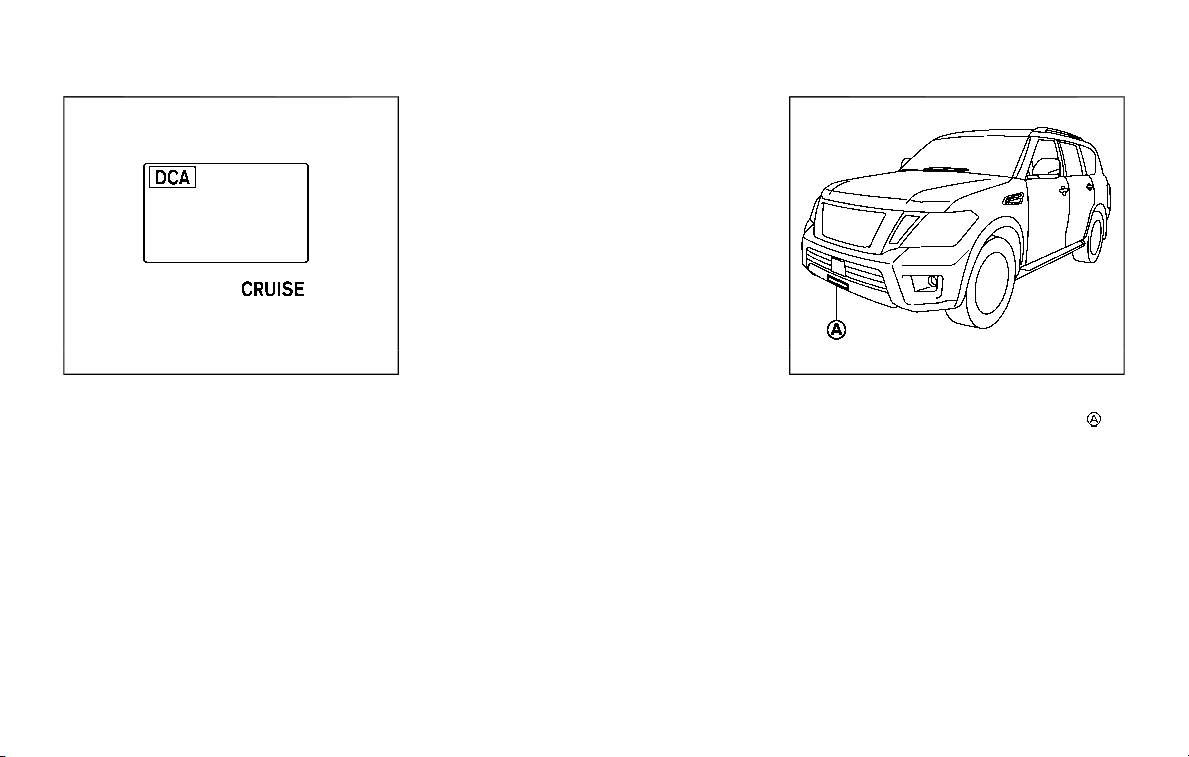
SSD0999
SYSTEM MALFUNCTION
Condition:
When the I-DC system is not operating
properly, the chime sounds and the
system warning light (“CRUISE” orange)
will come on.
Action to take:
If the warning light comes on, park the
vehicle in a safe place. Turn the engine off,
restart the engine, and turn on the I-DC
system again.
If it is not possible to set the system or
the indicator stays on, it may indicate
that the system is malfunctioning.
Although the vehicle is still driveable
under normal conditions, have the ve-
hicle checked. It is recommended you
visit a NISSAN dealer for this service.
JVS0913X
SYSTEM MAINTENANCE
The sensor for the I-DC system is
located below the front bumper.
The I-DC system is designed to automa-
tically check the sensor’s operation. When
the sensor is covered with dirt or is
obstructed, the system will automatically
be canceled. If the sensor is covered with
ice, a transparent or translucent vinyl bag,
etc., the I-DC system may not detect
them. In these instances, the I-DC system
may not be able to decelerate the vehicle
properly. Be sure to check and clean the
sensor regularly.
To keep the I-DC system operating prop-
erly, be sure to observe the following:
Starting and driving 5-97

5-98 Starting and driving
. Always keep the sensor area of the
front bumper clean.
. Do not strike or damage the areas
around the sensor.
. Do not cover or attach stickers or
similar objects on the front bumper
near the sensor area. This could cause
failure or malfunction.
. Do not attach metallic objects near
the sensor area (brush guard, etc.).
This could cause failure or malfunc-
tion.
. Do not alter, remove or paint the front
bumper. It is recommended you con-
tact a NISSAN dealer before customiz-
ing or restoring the front bumper.
FCC Notice:
For USA:
This device complies with Part 15 of the
FCC Rules. Operation is subject to the
following two conditions:
1. This device may not cause harmful
interference, and
2. This device must accept any inter-
ference received, including interfer-
ence that may cause undesired
operation.
FCC Warning
Changes or modification not expressly
approved by the party responsible for
compliance could void the user’s
authority to operate the equipment.
For Canada:
This device complies with Industry Ca-
nada licence-exempt RSS standard(s).
Operation is subject to the following
two conditions:
1. This device may not cause interfer-
ence, and
2. This device must accept any inter-
ference, including interference that
may cause undesired operation of
the device.
WARNING
Failure to follow the warnings and
instructions for proper use of the
AEB system could result in serious
injury or death.
. The AEB system is a supplemen-
tal aid to the driver. It is not a
replacement for the driver’s at-
tention to traffic conditions or
responsibility to drive safely. It
cannot prevent accidents due to
carelessness or dangerous driv-
ing techniques.
. The AEB system does not func-
tion in all driving, traffic, weather
and road conditions.
The AEB system can assist the driver
when there is a risk of a forward collision
with the vehicle ahead in the traveling
lane.
AUTOMATIC EMERGENCY BRAKING (AEB)

JVS0913X
The AEB system uses a sensor located
below the front bumper to measure the
distance to the vehicle ahead in the
traveling lane.
JVS1102X
Indicators and warnings (on the vehicle
information display)
AEB system warning light (on the instru-
ment panel)
Center multi-function control panel
AEB SYSTEM OPERATION
The AEB system operates at speeds
above approximately 3 MPH (5 km/h).
If a risk of a forward collision is detected,
the AEB system will provide the first
warning to the driver by blinking the
vehicle ahead detection indicator in the
Starting and driving 5-99

5-100 Starting and driving
vehicle information display and providing
an audible warning. In addition, the AEB
system pushes the accelerator pedal up.
If the driver releases the accelerator
pedal, then the system applies partial
braking.
If the driver applies the brakes quickly and
forcefully after the warning, and the AEB
system detects that there is still the
possibility of a forward collision, the
system will automatically increase the
braking force.
If a forward collision is imminent and the
driver does not take action, the AEB
system issues the second visual (flashing)
and audible warning and automatically
applies harder braking.
NOTE:
The vehicle’s stop lights come on when
braking is performed by the AEB sys-
tem.
Depending on vehicle speed and distance
to the vehicle ahead, as well as driving
and roadway conditions, the system may
help the driver avoid a forward collision or
may help mitigate the consequences of a
collision should one be unavoidable.
If the driver is handling the steering
wheel, accelerating or braking, the AEB
system will function later or will not
function.
The automatic braking will cease under
the following conditions:
. When the steering wheel is turned as
far as necessary to avoid a collision.
. When the accelerator pedal is de-
pressed.
. When there is no longer a vehicle
detected ahead.
If the AEB system has stopped the vehicle,
the vehicle will remain at a standstill for
approximately 2 seconds before the
brakes are released.
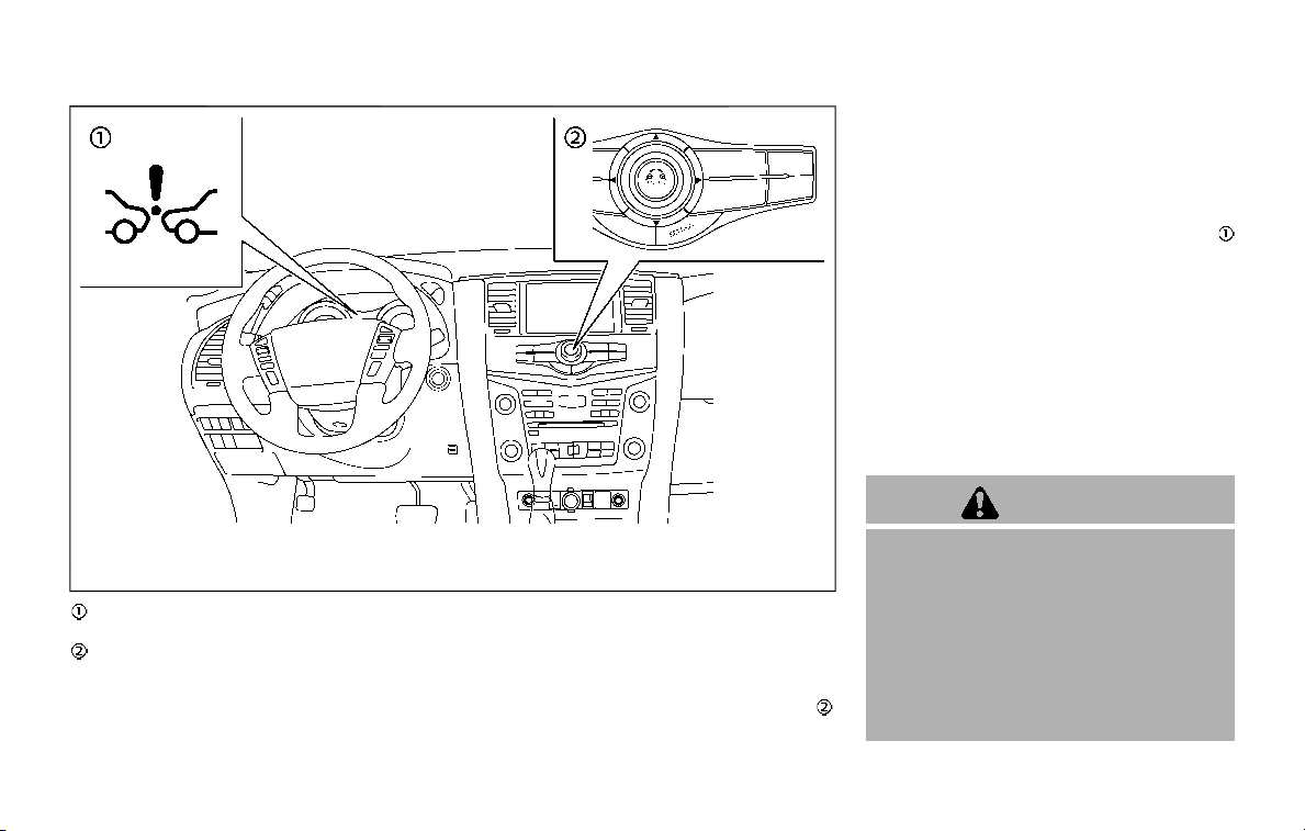
JVS1103X
AEB system warning light (on the instru-
ment panel)
Center multi-function control panel
TURNING THE AEB SYSTEM ON/OFF
Perform the following steps to turn the
AEB system ON/OFF.
1. Push the SETTING button on the
center multi-function control panel
.
2. Touch [Driver Assistance].
3. Touch [Emergency Assist].
4. Touch [Forward emergency braking]
to turn the system ON/OFF.
When the AEB system is turned off, the
AEB system warning light (orange)
illuminates.
NOTE:
The AEB system will be automatically
turned ON when the engine is restarted.
The I-FCW system is integrated into the
AEB system. There is not a separate
selection in the display for the I-FCW
system. When the AEB system is turned
off, the I-FCW system is also turned off.
AEB SYSTEM LIMITATIONS
WARNING
Listed below are the system limita-
tions for the AEB system. Failure to
operate the vehicle in accordance
with these system limitations could
result in serious injury or death.
. The AEB system cannot detect all
vehicles under all conditions.
. The radar sensor does not detect
the following objects:
Starting and driving 5-101

5-102 Starting and driving
— Pedestrians, animals or obsta-
cles in the roadway
— Oncoming vehicles
— Crossing vehicles
. The radar sensor has some per-
formance limitations. If a station-
ary vehicle is in the vehicle’s path,
the AEB system will not function
when the vehicle is driven at
speeds over approximately 45
MPH (70 km/h).
. The radar sensor may not detect
a vehicle ahead in the following
conditions:
— Dirt, ice, snow or other materi-
al covering the radar sensor.
— Interference by other radar
sources.
— Snow or road spray from tra-
veling vehicles.
— If the vehicle ahead is narrow
(e.g. motorcycle)
— When driving on a steep
downhill slope or roads with
sharp curves.
— When towing a trailer or other
vehicle.
. In some road or traffic conditions,
the AEB system may unexpect-
edly push the accelerator pedal
up or apply partial braking. When
acceleration is necessary, con-
tinue to depress the accelerator
pedal to override the system.
. Braking distances increase on
slippery surfaces.
. The system is designed to auto-
matically check the sensor’s func-
tionality, within certain
limitations. The system may not
detect some forms of obstruction
of the sensor area such as ice,
snow, stickers, for example. In
these cases, the system may not
be able to warn the driver prop-
erly. Be sure that you check, clean
and clear the sensor area regu-
larly.
. Excessive noise will interfere with
the warning chime sound, and
the chime may not be heard.
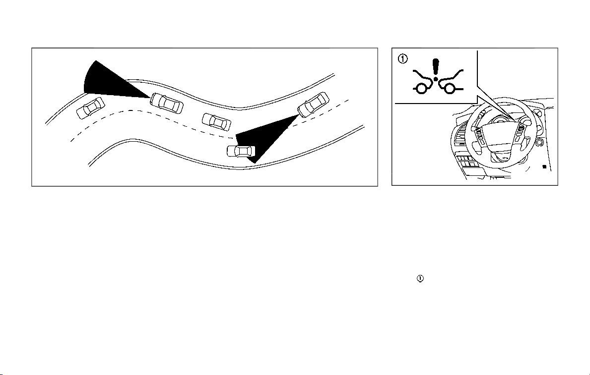
SSD0253
When driving on some roads, such as
winding, hilly, curved, narrow roads, or
roads which are under construction, the
radar sensor may detect vehicles in a
different lane, or may temporarily not
detect a vehicle traveling ahead. This
may cause the AEB system to work
inappropriately.
The detection of vehicles may also be
affected by vehicle operation (steering
maneuver or traveling position in the
lane, etc.) or vehicle condition. If this
occurs, the system may warn you by
blinking the vehicle ahead detection
indicator and sounding the chime un-
expectedly. You will have to manually
control the proper distance away from
the vehicle traveling ahead.
JVS0675X
SYSTEM TEMPORARILY UNAVAIL-
ABLE
Condition A
When the radar sensor picks up interfer-
ence from another radar source, making
it impossible to detect a vehicle ahead,
the AEB system is automatically turned
off. The AEB system warning light (or-
ange)
will illuminate.
Action to take:
When the above conditions no longer
exist, the AEB system will resume auto-
matically.
Starting and driving 5-103

5-104 Starting and driving
Condition B
Under the following conditions, making it
impossible to detect a vehicle ahead, the
AEB system is automatically turned off.
The AEB system warning light (orange)
will illuminate and the “FRONT RADAR
OBSTRUCTION” warning message will ap-
pear in the vehicle information display.
. When the sensor area of the front
bumper is covered with dirt or is
obstructed
Action to take:
If the AEB system warning light (orange)
comes on, stop the vehicle in a safe
place, place the shift lever in the P (Park)
position and turn the engine off. Clean
the radar cover below the front bumper
with a soft cloth, and restart the engine. If
the AEB system warning light continues
to illuminate, have the AEB system
checked. It is recommended you visit a
NISSAN dealer for this service.
. When driving on roads with limited
road structures or buildings (for ex-
ample, long bridges, deserts, snow
fields, driving next to long walls)
Action to take:
When the above conditions no longer
exist, the AEB system will resume auto-
matically.
Condition C
When the accelerator pedal actuator
detects that the internal motor tempera-
ture is high, the AEB system is automati-
cally turned off. The AEB system warning
light (orange)
will illuminate.
Action to take:
When the above conditions no longer
exist, the AEB system will resume auto-
matically.
Condition D
When VDC system is OFF, the AEB brake
will not operate. In this case only visible
and audible warning operates. The AEB
system warning light (orange) will illumi-
nate.
Action to take:
When the above conditions no longer
exist, the AEB system will resume auto-
matically.
SYSTEM MALFUNCTION
If the AEB system malfunctions, it will be
turned off automatically, a chime will
sound, the AEB system warning light
(orange)
will illuminate.
Action to take:
If the warning light (orange)
comes on,
stop the vehicle in a safe location and
place the shift lever in the P (Park)
position. Turn the engine off and restart
the engine. If the warning light continues
to illuminate, have the AEB system
checked. It is recommended you visit a
NISSAN dealer for this service.

JVS0913X
SYSTEM MAINTENANCE
The sensor
is located below the front
bumper.
To keep the system operating properly,
be sure to observe the following:
. Always keep the sensor area of the
front bumper clean.
. Do not strike or damage the areas
around the sensor.
. Do not cover or attach stickers or
similar objects on the front bumper
near the sensor area. This could cause
failure or malfunction.
. Do not attach metallic objects near
the sensor area (brush guard, etc.).
This could cause failure or malfunc-
tion.
. Do not alter, remove or paint the front
bumper. It is recommended you con-
tact a NISSAN dealer before customiz-
ing or restoring the front bumper.
FCC Notice:
For USA:
This device complies with Part 15 of the
FCC Rules. Operation is subject to the
following two conditions:
1. This device may not cause harmful
interference, and
2. This device must accept any inter-
ference received, including interfer-
ence that may cause undesired
operation.
FCC Warning
Changes or modification not expressly
approved by the party responsible for
compliance could void the user’s
authority to operate the equipment.
For Canada:
This device complies with Industry Ca-
nada licence-exempt RSS standard(s).
Operation is subject to the following
two conditions:
1. This device may not cause interfer-
ence, and
2. This device must accept any inter-
ference, including interference that
may cause undesired operation of
the device.
Starting and driving 5-105
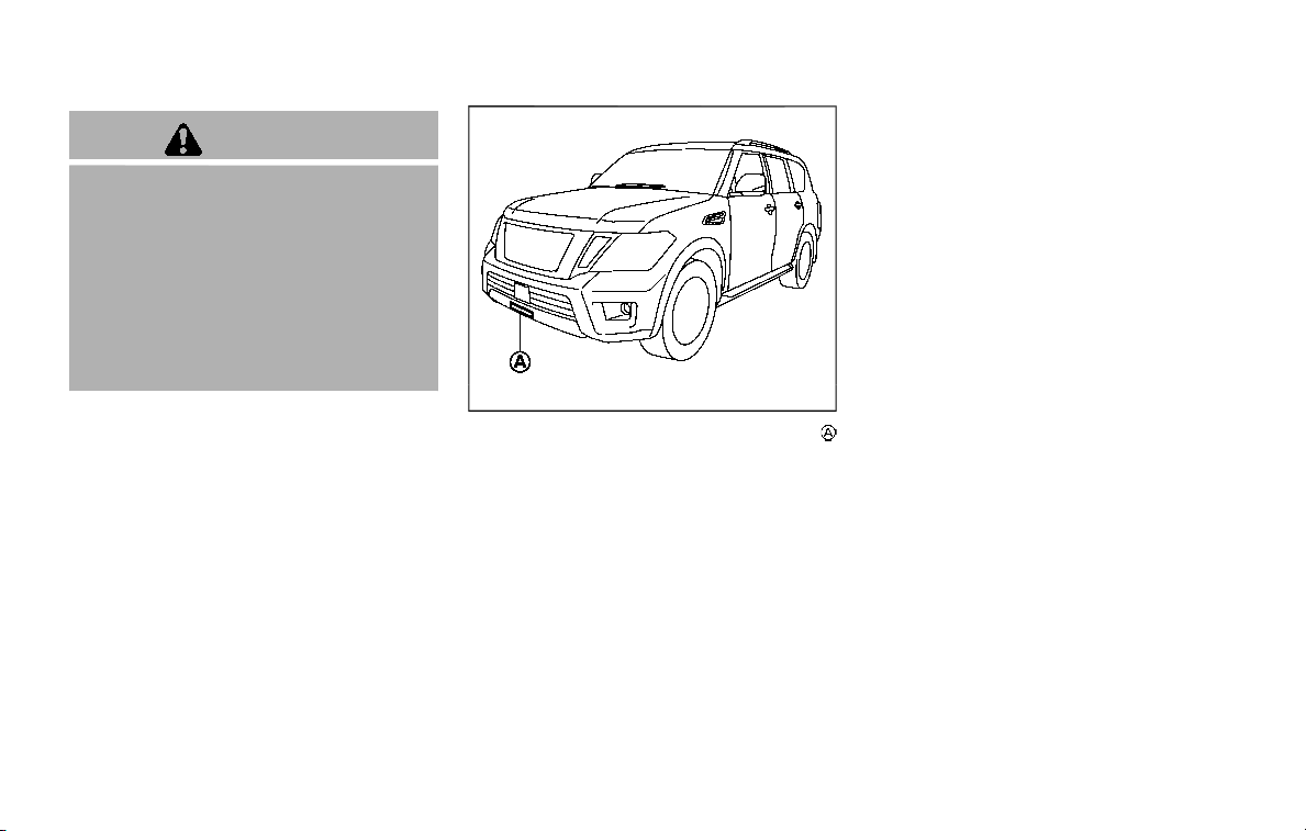
5-106 Starting and driving
WARNING
Failure to follow the warnings and
instructions for proper use of the I-
FCW system could result in serious
injury or death.
. The I-FCW system helps warn the
driver before a collision but will
not avoid a collision. It is the
driver’s responsibility to stay
alert, drive safely and be in con-
trol of the vehicle at all times.
The I-FCW system can help alert the driver
when there is a sudden braking of a
second vehicle traveling in front of the
vehicle ahead in the same lane.
JVS0913X
The I-FCW system uses a radar sensor
located below the front bumper to mea-
sure the distance to a second vehicle
ahead in the same lane.
INTELLIGENT FORWARD COLLISION
WARNING (I-FCW)
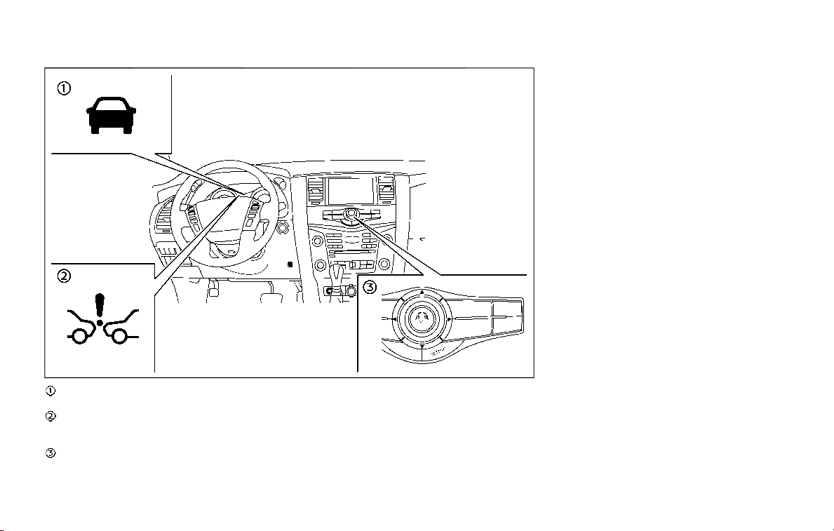
JVS1104X
Vehicle ahead detection indicator (on the
vehicle information display)
Automatic Emergency Braking (AEB) sys-
tem warning light (on the instrument
panel)
Center multi-function control panel
Starting and driving 5-107
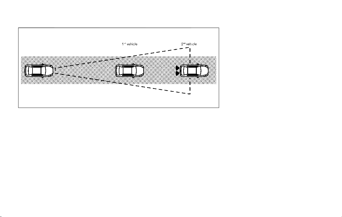
5-108 Starting and driving
JVS0294X
I-FCW SYSTEM OPERATION
The I-FCW system operates at speeds
above approximately 3 MPH (5 km/h).
If there is a potential risk of a forward
collision, the I-FCW system will warn the
driver by blinking the vehicle ahead
detection indicator, and sounding an
audible alert.
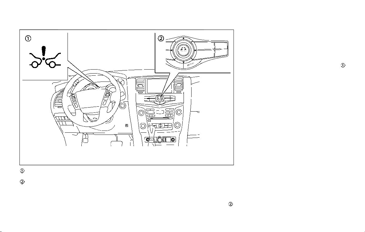
JVS1103X
AEB system warning light (on the instru-
ment panel)
Center multi-function control panel
TURNING THE I-FCW SYSTEM ON/
OFF
Perform the following steps to turn the I-
FCW system on or off.
1. Push the SETTING button on the
center multi-function control panel
.
2. Touch [Driver Assistance].
3. Touch [Emergency Assist].
4. Touch [Forward emergency braking]
to turn the system ON/OFF.
When the I-FCW system is turned off, the
AEB system warning light (orange)
illuminates.
NOTE:
The I-FCW system is integrated into the
AEB system. There is not a separate
selection in the display for the I-FCW
system. When the AEB system is turned
off, the I-FCW system is also turned off.
Starting and driving 5-109
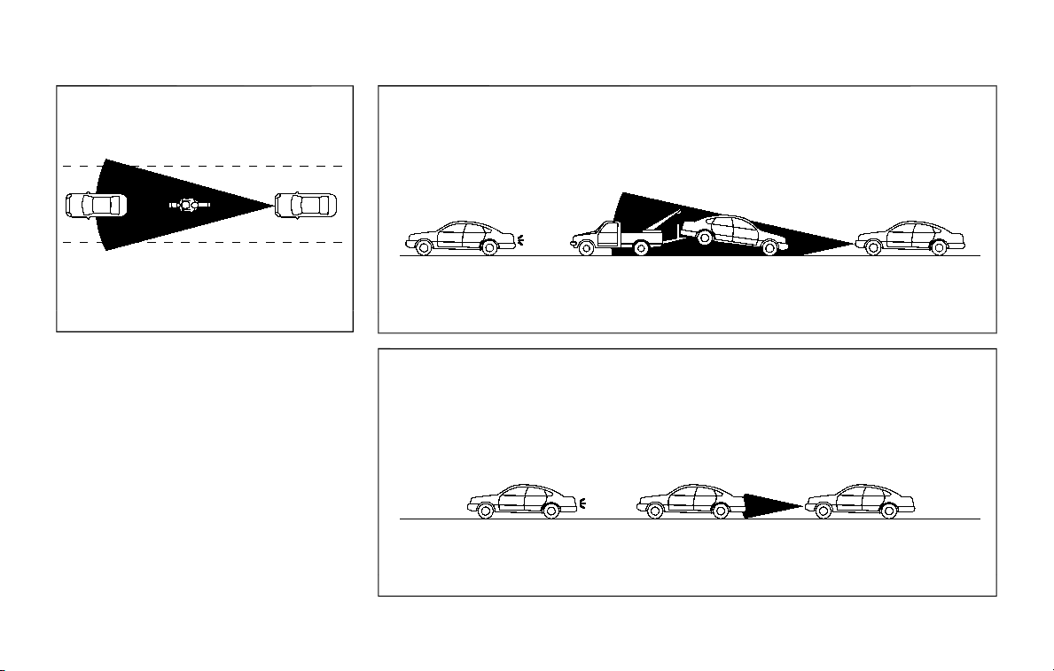
5-110 Starting and driving
JVS0295X
Illustration A
JVS0296X
Illustration B
JVS0297X
Illustration C
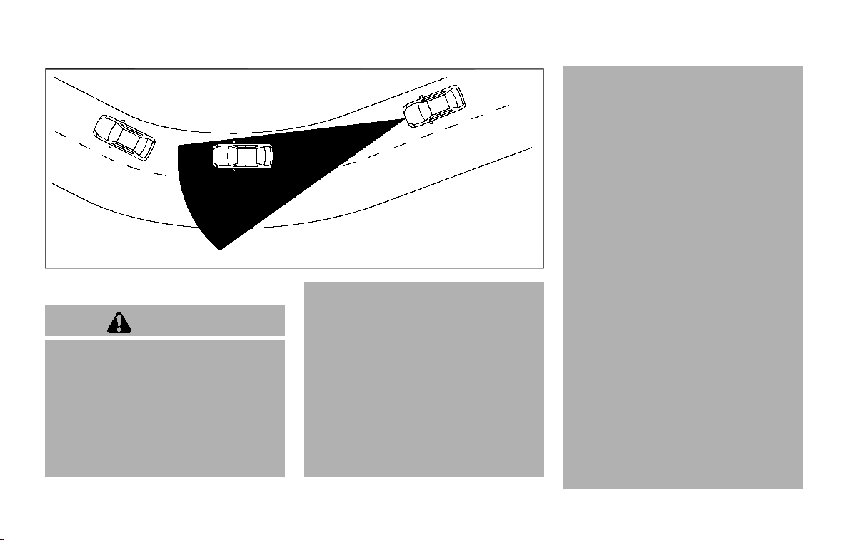
JVS0298X
Illustration D
I-FCW SYSTEM LIMITATIONS
WARNING
Listed below are the system limita-
tions for the I-FCW system. Failure to
operate the vehicle in accordance
with these system limitations could
result in serious injury or death.
. The I-FCW system cannot detect
all vehicles under all conditions.
. The radar sensor does not detect
the following objects:
— Pedestrians, animals or obsta-
cles in the roadway
— Oncoming vehicles
— Crossing vehicles
. (Illustration A) The I-FCW system
does not function when a vehicle
ahead is a narrow vehicle, such as
a motorcycle.
. The radar sensor may not detect
a vehicle ahead in the following
conditions:
— Snow or heavy rain
— Dirt, ice, snow or other materi-
al covering the radar sensor
— Interference by other radar
sources
— Snow or road spray from tra-
velling vehicles.
— Driving in a tunnel
— Towing a trailer or other vehi-
cle
. (Illustration B) When the vehicle
ahead is being towed.
. (Illustration C) When the distance
to the vehicle ahead is too close,
the beam of the radar sensor is
obstructed.
. (Illustration D) When driving on a
steep downhill slope or roads
with sharp curves.
. The system is designed to auto-
matically check the sensor’s func-
tionality, within certain
limitations. The system may not
detect some forms of obstruction
of the sensor area such as ice,
snow, stickers, for example. In
these cases, the system may not
be able to warn the driver prop-
erly. Be sure that you check, clean
and clear the sensor area regu-
Starting and driving 5-111
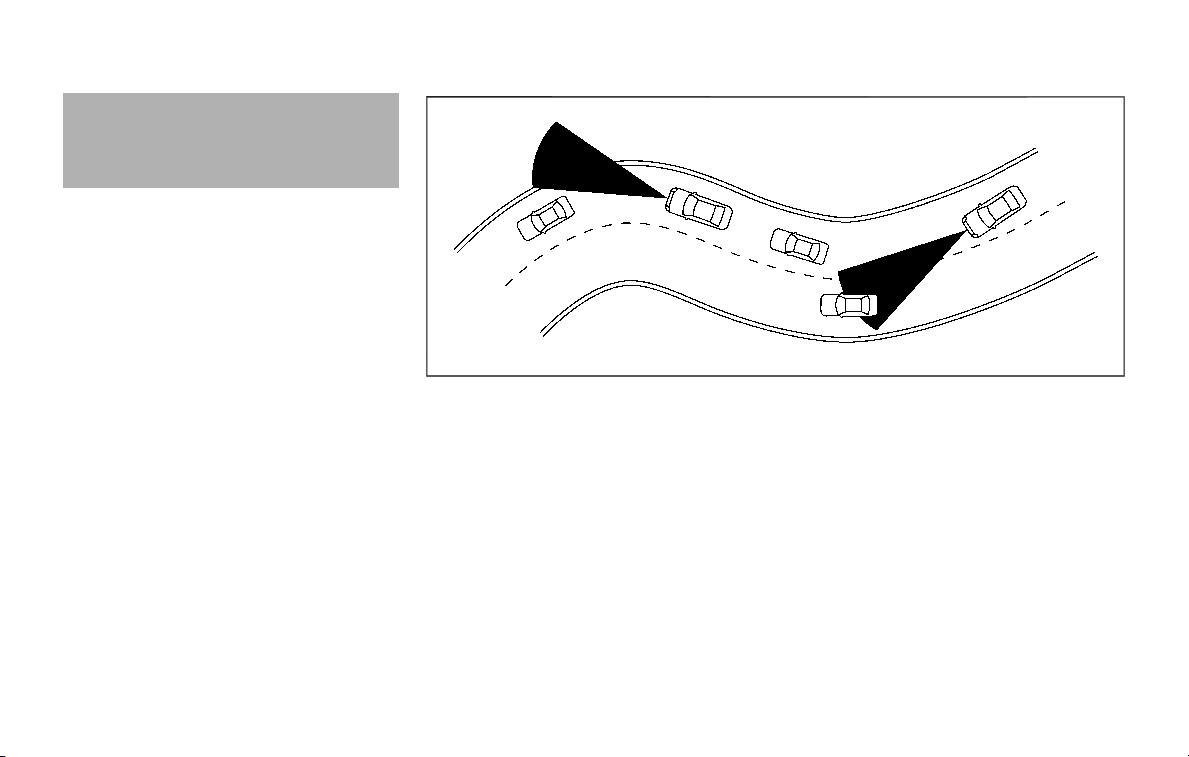
5-112 Starting and driving
larly.
. Excessive noise will interfere with
the warning chime sound, and
the chime may not be heard.
SSD0253
When driving on some roads, such as
winding, hilly, curved, narrow roads, or
roads which are under construction, the
radar sensor may detect vehicles in a
different lane, or may temporarily not
detect a vehicle traveling ahead. This
may cause the I-FCW system to work
inappropriately.
The detection of vehicles may also be
affected by vehicle operation (steering
maneuver or traveling position in the
lane, etc.) or vehicle condition. If this
occurs, the system may warn you by
blinking the vehicle ahead detection
indicator and sounding the chime un-
expectedly. You will have to manually
control the proper distance away from
the vehicle traveling ahead.
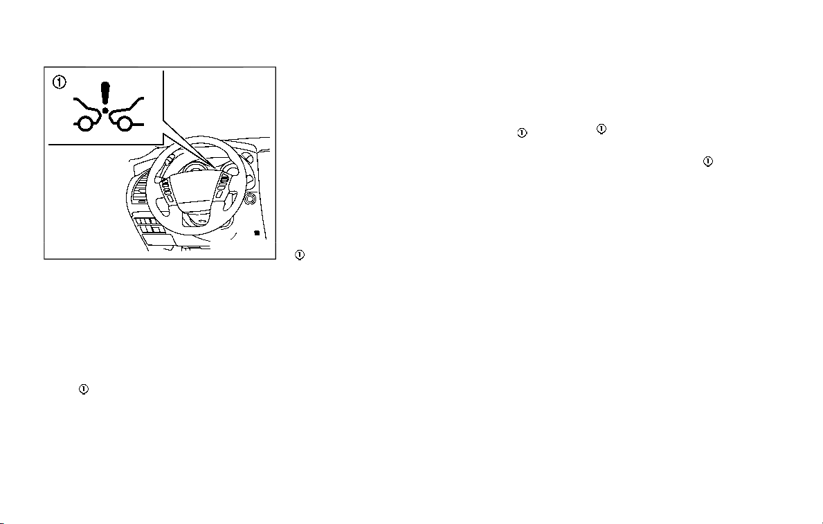
JVS0675X
SYSTEM TEMPORARILY UNAVAIL-
ABLE
Condition A
When the radar sensor picks up interfer-
ence from another radar source, making
it impossible to detect a vehicle ahead,
the I-FCW system is automatically turned
off. The AEB system warning light (or-
ange)
will illuminate.
Action to take:
When the above conditions no longer
exist, the I-FCW system will resume auto-
matically.
Condition B
Under the following conditions, making it
impossible to detect a vehicle ahead, the
I-FCW system is automatically turned off.
The AEB system warning light (orange)
will illuminate and the “FRONT RADAR
OBSTRUCTION” warning message will ap-
pear in the vehicle information display.
. When the sensor area of the front
bumper is covered with dirt or is
obstructed
Action to take:
If the AEB system warning light (orange)
comes on, stop the vehicle in a safe
place, place the shift lever in the P (Park)
position and turn the engine off. Clean
the radar cover below the front bumper
with a soft cloth, and restart the engine. If
the warning light continues to illuminate,
have the I-FCW system checked. It is
recommended you visit a NISSAN dealer
for this service.
. When driving on roads with limited
road structures or buildings (for ex-
ample, long bridges, deserts, snow
fields, driving next to long walls)
Action to take:
When the above conditions no longer
exist, the I-FCW system will resume auto-
matically.
SYSTEM MALFUNCTION
If the I-FCW system malfunctions, it will be
turned off automatically, a chime will
sound, the AEB system warning light
(orange)
will illuminate.
Action to take:
If the warning light (orange)
illuminates,
stop the vehicle in a safe location and
place the shift lever in the P (Park)
position. Turn the engine off and restart
the engine. If the warning light continues
to illuminate, have the I-FCW system
checked. It is recommended you visit a
NISSAN dealer for this service.
Starting and driving 5-113
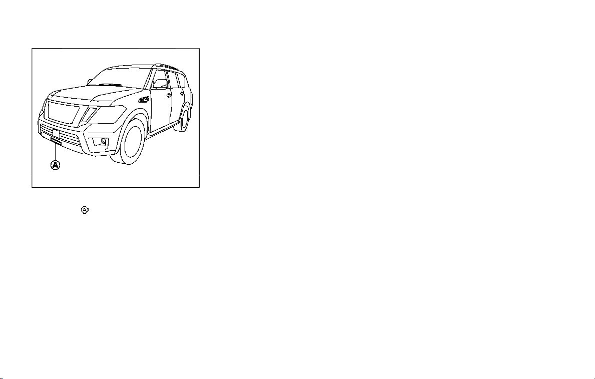
5-114 Starting and driving
JVS0913X
SYSTEM MAINTENANCE
The sensor
is located below the front
bumper.
To keep the system operating properly,
be sure to observe the following:
. Always keep the sensor area of the
front bumper clean.
. Do not strike or damage the areas
around the sensor.
. Do not cover or attach stickers or
similar objects on the front bumper
near the sensor area. This could cause
failure or malfunction.
. Do not attach metallic objects near
the sensor area (brush guard, etc.).
This could cause failure or malfunc-
tion.
. Do not alter, remove or paint the front
bumper. It is recommended you con-
tact a NISSAN dealer before customiz-
ing or restoring the front bumper.
FCC Notice:
For USA:
This device complies with Part 15 of the
FCC Rules. Operation is subject to the
following two conditions:
1. This device may not cause harmful
interference, and
2. This device must accept any inter-
ference received, including interfer-
ence that may cause undesired
operation.
FCC Warning
Changes or modification not expressly
approved by the party responsible for
compliance could void the user’s
authority to operate the equipment.
For Canada:
This device complies with Industry Ca-
nada licence-exempt RSS standard(s).
Operation is subject to the following
two conditions:
1. This device may not cause interfer-
ence, and
2. This device must accept any inter-
ference, including interference that
may cause undesired operation of
the device.

CAUTION
During the first 1,200 miles (2,000
km), follow these recommendations
to obtain maximum engine perfor-
mance and ensure the future relia-
bility and economy of your new
vehicle.
Failure to follow these recommenda-
tions may result in shortened engine
life and reduced engine perfor-
mance.
. Avoid driving for long periods at con-
stant speed, either fast or slow. Do not
run the engine over 4,000 rpm.
. Do not accelerate at full throttle in any
gear.
. Avoid quick starts.
. Avoid hard braking as much as possi-
ble.
. Do not tow a trailer for the first 500
miles (805 km).
Follow these easy-to-use Fuel Efficient
Driving Tips to help you achieve the most
fuel economy from your vehicle.
1. Use smooth accelerator and brake
pedal application.
.
Avoid rapid starts and stops.
.
Use smooth, gentle accelerator and
brake application whenever possi-
ble.
.
Maintain constant speed while
commuting and coast whenever
possible.
2. Maintain constant speed.
.
Look ahead to try and anticipate
and minimize stops.
.
Synchronizing your speed with traf-
fic lights allows you to reduce your
number of stops.
.
Maintaining a steady speed can
minimize red light stops and im-
prove fuel efficiency.
3. Use air conditioning (A/C) at higher
vehicle speeds.
.
Below 40 MPH (64 km/h), it is more
efficient to open windows to cool
the vehicle due to reduced engine
load.
.
Above 40 MPH (64 km/h), it is more
efficient to use A/C to cool the
vehicle due to increased aerody-
namic drag.
.
Recirculating the cool air in the
cabin when the A/C is on reduces
cooling load.
4. Drive at economical speeds and dis-
tances.
.
Observing the speed limit and not
exceeding 60 MPH (97 km/h)
(where legally allowed) can improve
fuel efficiency due to reduced aero-
dynamic drag.
.
Maintaining a safe following dis-
tance behind other vehicles re-
duces unnecessary braking.
.
Safely monitoring traffic to antici-
pate changes in speed permits
reduced braking and smooth accel-
eration changes.
.
Select a gear range suitable to road
conditions.
5. Use cruise control.
.
Using cruise control during highway
driving helps maintain a steady
speed.
.
Cruise control is particularly effec-
tive in providing fuel savings when
driving on flat terrains.
6. Plan for the shortest route.
.
Utilize a map or navigation system
to determine the best route to save
time.
Starting and driving 5-115
BREAK-IN SCHEDULE FUEL EFFICIENT DRIVING TIPS

5-116 Starting and driving
7. Avoid idling.
.
Shutting off your engine when safe
for stops exceeding 30-60 seconds
saves fuel and reduces emissions.
8. Buy an automated pass for toll roads.
.
Automated passes permit drivers to
use special lanes to maintain cruis-
ing speed through the toll and
avoid stopping and starting.
9. Winter warm up.
.
Limit idling time to minimize impact
to fuel economy.
.
Vehicles typically need no more
than 30 seconds of idling at start-
up to effectively circulate the en-
gine oil before driving.
.
Your vehicle will reach its ideal
operating temperature more
quickly while driving versus idling.
10. Keeping your vehicle cool.
.
Park your vehicle in a covered
parking area or in the shade when-
ever possible.
.
When entering a hot vehicle, open-
ing the windows will help to reduce
the inside temperature faster, re-
sulting in reduced demand on your
A/C system.
. Keep your engine tuned up.
. Follow the recommended scheduled
maintenance.
. Keep the tires inflated to the correct
pressure. Low tire pressure increases
tire wear and lowers fuel economy.
. Keep the wheels in correct alignment.
Improper alignment increases tire
wear and lowers fuel economy.
. Use the recommended viscosity en-
gine oil. (See “Engine oil and oil filter
recommendation” (P.10-5).)
WARNING
. Do not attempt to raise two
wheels off the ground and shift
the transmission to any drive or
reverse position with the engine
running. Doing so may result in
drivetrain damage or unexpected
vehicle movement which could
result in serious vehicle damage
or personal injury.
. Do not attempt to test a 4WD
equipped vehicle on a 2-wheel
dynamometer or similar equip-
ment even if the other two
wheels are raised off the ground.
Make sure you inform test facility
personnel that your vehicle is
equipped with 4WD before it is
placed on a dynamometer. Using
the wrong test equipment may
result in drivetrain damage or
unexpected vehicle movement
which could result in serious ve-
hicle damage or personal injury.
INCREASING FUEL ECONOMY
NISSAN ALL-MODE 4WD® (if so equipped)

CAUTION
. Do not drive the vehicle in the 4HI
or 4LO position on dry hard sur-
face roads. Driving on dry, hard
surfaces in 4HI or 4LO may cause
unnecessary noise, tire wear and
increased fuel consumption.
If the Four-Wheel Drive (4WD)
warning light turns on when driv-
ing on dry hard surface roads:
— in the 4HI position, shift the
4WD shift switch to AUTO.
— in the 4LO position, stop the
vehicle and shift the transmis-
sion lever to the N (Neutral)
position with the brake pedal
depressed and shift the 4WD
shift switch to AUTO.
If the 4WD warning light is still
on after the above operation,
have your vehicle checked as
soon as possible. It is recom-
mended you visit a NISSAN
dealer for this service.
. The transfer case may be da-
maged if you continue driving
with the 4WD warning light blink-
ing.
See “On-pavement and off-road driving
precautions” (P.5-9) for other precautions
for offroad driving.
NISSAN ALL-MODE 4WD® SYSTEM
The all mode 4WD system provides 3
positions (AUTO, 4HI and 4LO), so you
can select the desired drive mode accord-
ing to the driving conditions.
4WD shift procedure:
Starting and driving 5-117
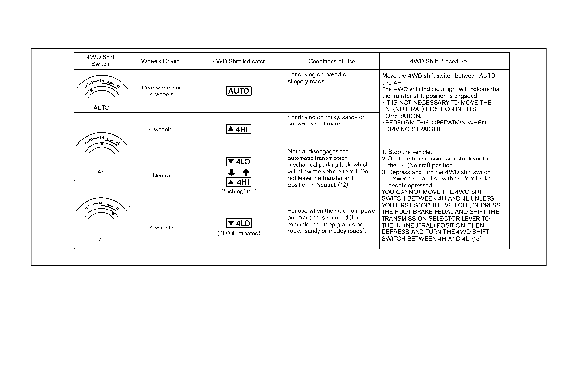
5-118 Starting and driving
SSD1100
*1: The 4LO and 4HI indicator may flash alternately. Stop the vehicle and be sure to turn the 4WD shift switch after the transmission
shift lever has been shifted to the N (Neutral) position. If the indicator keeps flashing after the 4WD shift procedure, drive slowly
without abrupt maneuvers for a while. Then the indicator will illuminate or turn off.
· Avoid making a turn or abrupt starts while shifting to the 4LO position. Otherwise the gears may grind, damaging the drive system.
*2: While changing in and out of the 4LO position, the engine must be running. Otherwise, the shift will not take place and the 4LO
indicator will not be on or flashing.

*3: Make sure that the 4LO indicator turns on when shifting the 4WD shift switch to the 4L position. The Vehicle Dynamic Control
(VDC) off indicator light will also turn on when 4L is selected. (See “Vehicle Dynamic Control (VDC) system” (P.5-133).)
Starting and driving 5-119

5-120 Starting and driving
The 4WD shift switch is used to select the
4WD mode depending on the driving
conditions. There are 3 types of drive
modes available, AUTO, 4HI and 4LO.
The 4WD shift switch electronically con-
trols the transfer case operation. Rotate
the switch to move between each mode,
AUTO, 4H and 4L.
You must depress the 4WD shift switch
to select 4L, and the vehicle MUST be
stationary and the shift lever in the N
(Neutral) position when changing into
or out of 4L.
WARNING
. When parking, apply the parking
brake before stopping the engine
and make sure that the 4WD shift
indicator is on and the ATP warn-
ing light turns off. Otherwise, the
vehicle could unexpectedly move
even if the automatic transmis-
sion is in the P (Park) position.
. The 4LO and 4HI indicators must
stop blinking and the 4LO or 4HI
indicator must remain illumi-
nated or turn off before shifting
the transmission into gear. If the
shift lever is shifted from the N
(Neutral) position to any other
gear while the 4LO and 4HI in-
dicators are blinking alternately,
the vehicle may move unexpect-
edly.
CAUTION
. Never shift the 4WD shift switch
between 4L and 4H while driving.
. The 4HI position provides greater
traction. Avoid excessive speed,
as it will cause increased fuel
consumption and higher oil tem-
peratures, and could damage dri-
vetrain component. Speeds over
62 MPH (100 km/h) in 4HI is not
recommended.
. The 4LO position provides max-
imum traction. Avoid raising ve-
hicle speed excessively, as the
maximum speed is approxi-
mately 31 MPH (50 km/h).
. When driving straight, shift the
4WD shift switch to the AUTO or
4H position. Do not move the 4WD
shift switch when making a turn
or reversing.
. Do not shift the 4WD shift switch
(between AUTO and 4H) while
driving on steep downhill grades.
Use the engine brake and low
automatic transmission gears
for engine braking.
. Do not operate the 4WD shift
switch (between AUTO and 4H)
with the rear wheels spinning.
. Do not drive on dry hard surface
roads in the 4HI or 4LO position.
Driving on dry hard surfaces in
4HI or 4LO may cause unneces-
sary noise and tire wear. NISSAN
recommends driving in the AUTO
position under these conditions.
. The 4WD transfer case may not
be shifted between 4HI and 4LO
at low ambient temperatures and
the 4LO and 4HI indicators may
blink even when the 4WD shift
switch is shifted. After driving for
a while you can change the 4WD
shift switch between 4H and 4L.
When driving on rough roads,
. Drive carefully according to the road
surface conditions.
When the vehicle is stuck,
. Place stones or wooden blocks under
the tires to free the vehicle.
. Set the 4WD shift switch to 4H or 4L.
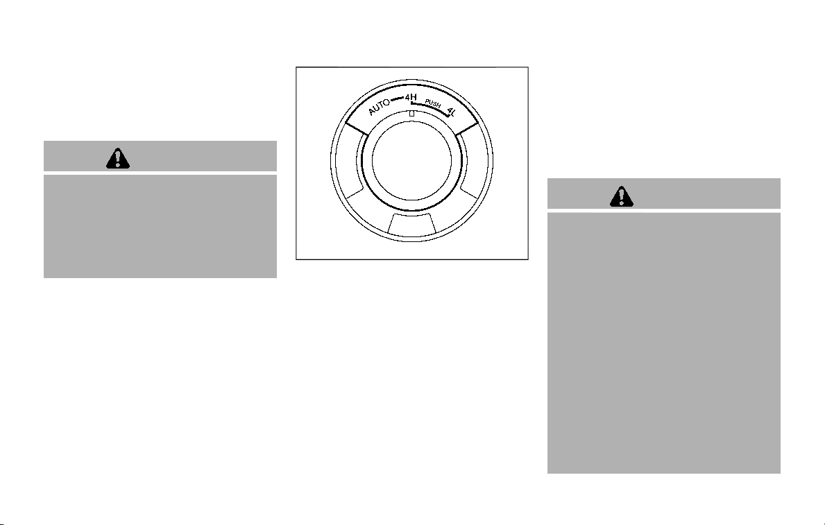
. If it is difficult to free the vehicle,
repeat forward and backward move-
ment to increase the movement.
. If the vehicle is stuck deep in mud, tire
chains may be effective.
CAUTION
. Do not spin the tires excessively.
Tires will sink deep into the mud,
making it difficult to free the
vehicle.
. Avoid shifting gears with the en-
gine running at high speeds as
this may cause malfunction.
SSD1048
4WD SHIFT SWITCH
. Shift the 4WD shift switch to either the
AUTO, 4H or 4L position, depending on
driving conditions.
. With the switch set to the AUTO
position, distribution of torque to the
front and rear wheels changes auto-
matically, depending on road condi-
tions encountered [ratio; 0 : 100 (2WD)
? 50 : 50 (4WD)]. This results in
improved driving stability.
. If the 4WD shift switch is operated
while making a turn, accelerating or
decelerating or if the ignition switch
is placed in the OFF position while in
the AUTO, 4H or 4L, you may feel a
jolt. This is not abnormal.
. When the vehicle is stopped after
making a turn, you may feel a slight
jolt after the shift lever is shifted to N
(Neutral) or P (Park) position. This
occurs because the transfer clutch is
released and not because of a mal-
function.
CAUTION
. When driving straight, shift the
4WD shift switch to the AUTO or
4H position. Do not move the 4WD
shift switch when making a turn
or reversing.
. Do not shift the 4WD shift switch
while driving on steep downhill
grades. Use the engine brake and
low automatic transmission
gears for engine braking.
. Do not operate the 4WD shift
switch with the rear wheels spin-
ning.
. Before placing the 4WD shift
switch in the 4H position from
AUTO, ensure the vehicle speed is
less than 62 MPH (100 km/h).
Failure to do so can damage the
4WD system.
Starting and driving 5-121
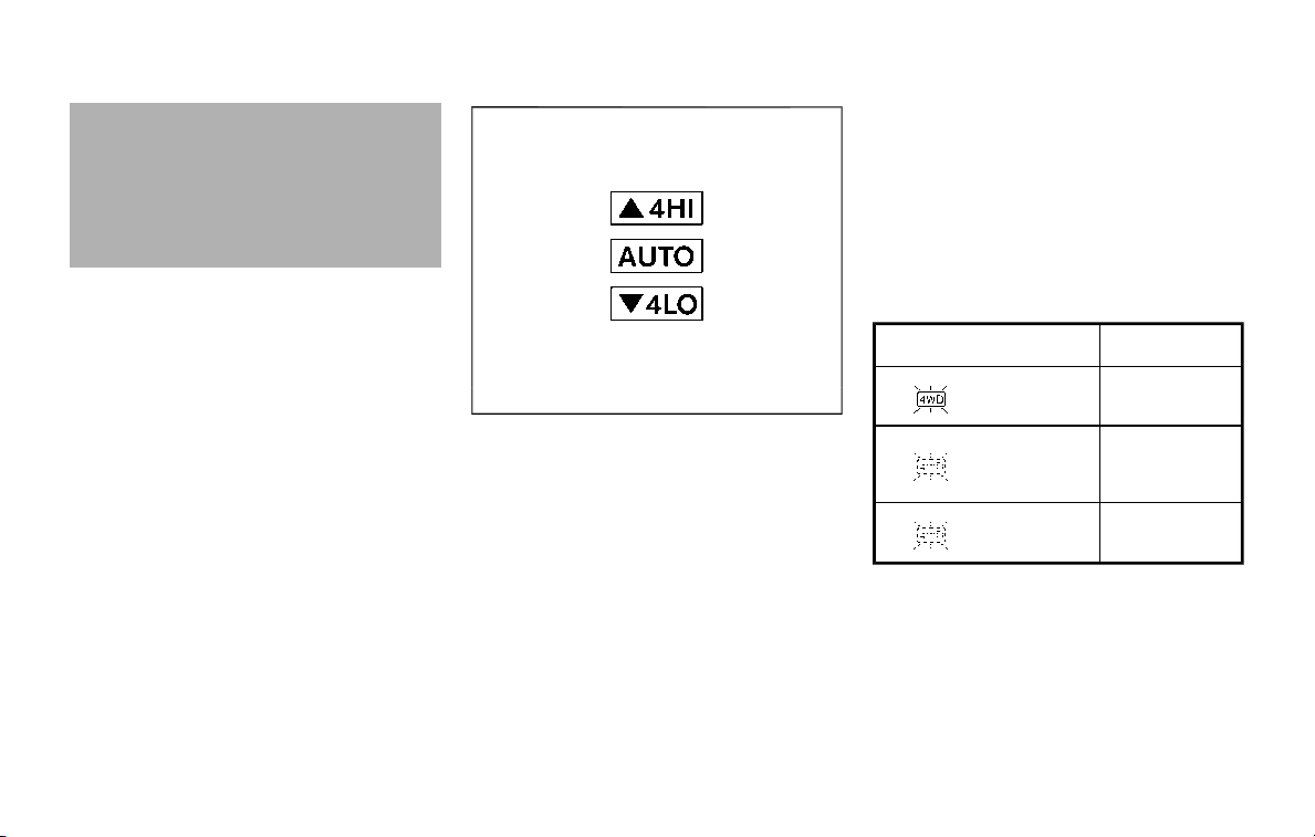
5-122 Starting and driving
. Never shift the 4WD shift switch
between 4L and 4H while driving.
. Engine idling speed is high while
warming up the engine. Be espe-
cially careful when starting or
driving on slippery surfaces with
the 4WD shift switch in AUTO.
SSD1058
4WD shift indicator
4WD SHIFT INDICATOR
The 4WD shift indicator is displayed in the
vehicle information display.
The indicator should turn off within 1
second after placing the ignition switch
in the ON position.
While the engine is running, the 4WD shift
indicator will illuminate the position se-
lected by the 4WD shift switch. (See the
4WD shift procedure list shown in the
“NISSAN all-mode 4WD® system” (P.5-117).)
. The 4WD shift indicator may blink
while shifting from one drive mode
to the other. When the shifting is
completed, the 4WD shift indicator
will come on. If the indicator does
not come on immediately, make
sure the area around the vehicle is
safe, and drive the vehicle straight,
accelerate or decelerate or move the
vehicle in reverse, then shift the 4WD
shift switch.
. If the 4WD warning light comes on, the
4WD shift indicator turns off.
4WD WARNING LIGHT
Warning light
Comes on or
blinks when:
Illuminates
There is a mal-
function in the
4WD system
Blinks ra-
pidly
The transfer
case oil tem-
perature is ab-
normally high
Blinks slowly
The difference
in wheel rota-
tion is large
The 4WD warning light is located in the
meter.
The 4WD warning light comes on when
the ignition switch is placed in the ON
position. It turns off soon after the engine
is started.
If any malfunction occurs in the 4WD
system when the ignition switch is placed
in the ON position, the 4WD warning light

will either remain illuminated or blink.
If the 4WD warning light comes on, the
4WD shift indicator turns off.
High-temperature transfer case oil makes
the 4WD warning light blink rapidly (about
twice per second). If the warning light
blinks rapidly during operation, stop the
vehicle in a safe place immediately. Then
if the light turns off after a while, you can
continue driving.
A large difference between the diameters
of front and rear wheels will make the
4WD warning light blink slowly (about
once per two seconds). Change the 4WD
shift switch to AUTO and do not drive fast.
CAUTION
. If the 4WD warning light comes
on or blinks slowly during opera-
tion or rapidly after stopping the
vehicle for a while, have your
vehicle checked as soon as pos-
sible. It is recommended you visit
a NISSAN dealer for this service.
. Shifting between 4HI and 4LO is
not recommended when the 4WD
warning light turns on.
. When the 4WD warning light
comes on, the 2WD mode may
be engaged even if the 4WD shift
switch is in AUTO or 4H. Be
especially careful when driving. If
corresponding parts are malfunc-
tioning, the 4WD mode will not be
engaged even if the 4WD shift
switch is shifted.
. Do not drive the vehicle in the 4HI
or 4LO position on dry hard sur-
face roads. Driving on dry, hard
surfaces in 4HI or 4LO may cause
unnecessary noise, tire wear and
increased fuel consumption.
If the 4WD warning light turns on
when driving on dry hard surface
roads:
— in the AUTO or 4HI position,
shift the 4WD shift switch to
AUTO.
— in the 4LO position, stop the
vehicle and shift the transmis-
sion shift lever to the N (Neu-
tral) position and shift the
4WD shift switch to AUTO.
. If the 4WD warning light is still on
after the above operation, have
your vehicle checked as soon as
possible. It is recommended you
visit a NISSAN dealer for this
service.
. The transfer case may be da-
maged if you continue driving
with the warning light blinking.
Starting and driving 5-123

5-124 Starting and driving
WARNING
. Never rely solely on the hill start
assist system to prevent the ve-
hicle from moving backward on a
hill. Always drive carefully and
attentively. Depress the brake
pedal when the vehicle is stopped
on a steep hill. Be especially care-
ful when stopped on a hill on
frozen or muddy roads. Failure
to prevent the vehicle from rolling
backwards may result in a loss of
control of the vehicle and possi-
ble serious injury or death.
. The hill start assist system is not
designed to hold the vehicle at a
standstill on a hill. Depress the
brake pedal when the vehicle is
stopped on a steep hill. Failure to
do so may cause the vehicle to
roll backwards and may result in
a collision or serious personal
injury.
. The hill start assist system may
not prevent the vehicle from roll-
ing backwards on a hill under all
load or road conditions. Always
be prepared to depress the brake
pedal to prevent the vehicle from
rolling backwards. Failure to do
so may result in a collision or
serious personal injury.
The hill start assist system automatically
keeps the brakes applied to help prevent
the vehicle from rolling backwards in the
time it takes the driver to release the
brake pedal and apply the accelerator
when the vehicle is stopped on a hill.
The hill start assist system will operate
automatically under the following condi-
tions:
. The transmission is shifted to a for-
ward or reverse gear.
. The vehicle is stopped completely on a
hill by applying the brake.
The maximum holding time is 2 seconds.
After 2 seconds the vehicle will begin to
roll back and the hill start assist system
will stop operating completely.
The hill start assist system will not
operate when the transmission is shifted
to the N (Neutral) or P (Park) position or
on a flat and level road.
When the Vehicle Dynamic Control (VDC)
warning light illuminates in the meter, the
hill start assist system will not operate.
(See “Warning lights, indicator lights and
audible reminders” (P.2-10).)
HILL START ASSIST SYSTEM
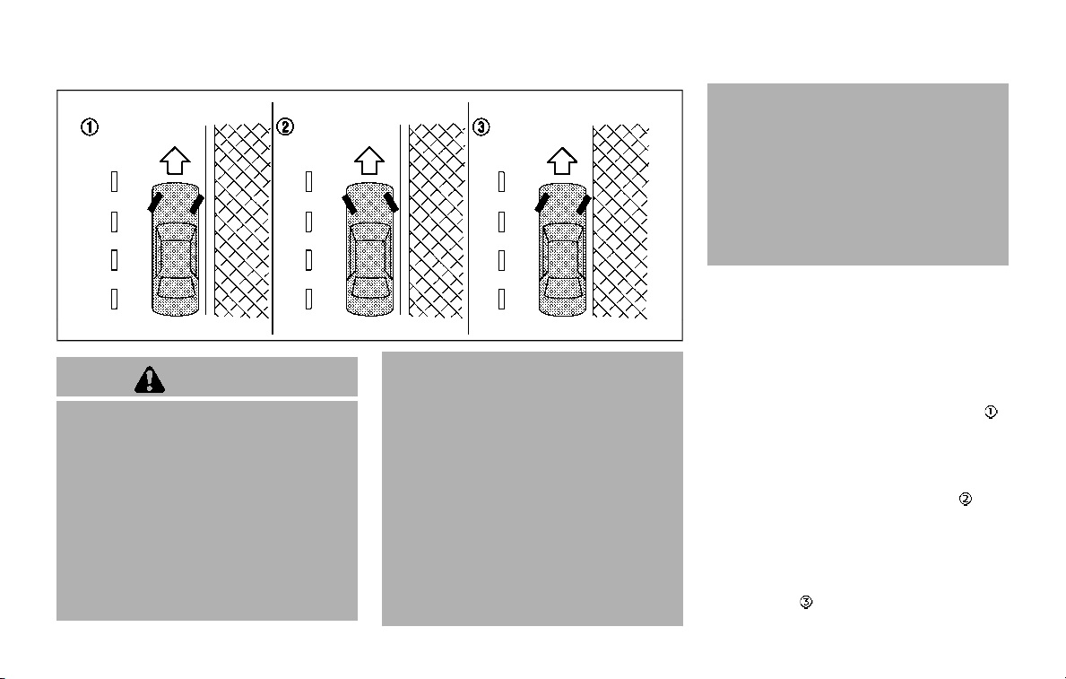
SD1006MA
WARNING
. Do not stop or park the vehicle
over flammable materials such as
dry grass, waste paper or rags.
They may ignite and cause a fire.
. Never leave the engine running
while the vehicle is unattended.
. Do not leave children unattended
inside the vehicle. They could
unknowingly activate switches
or controls. Unattended children
could become involved in serious
accidents.
. To help avoid risk of injury or
death through unintended opera-
tion of the vehicle and/or its
systems, do not leave children,
people who require the assis-
tance of others or pets unat-
tended in your vehicle.
Additionally, the temperature in-
side a closed vehicle on a warm
day can quickly become high
enough to cause a significant risk
of injury or death to people and
pets.
. Safe parking procedures require
that both the parking brake be
applied and the transmission be
placed in the P (Park) position.
Failure to do so could cause the
vehicle to move unexpectedly or
roll away and result in an acci-
dent.
. Make sure the automatic trans-
mission shift lever has been
pushed as far forward as it can
go and cannot be moved without
depressing the foot brake pedal.
1. Firmly apply the parking brake.
2. Move the shift lever to the P (Park)
position.
3. To help prevent the vehicle from roll-
ing into the street when parked on a
sloping drive way, it is a good practice
to turn the wheels as illustrated.
.
HEADED DOWNHILL WITH CURB:
Turn the wheels into the curb and
move the vehicle forward until the
curb side wheel gently touches the
curb.
.
HEADED UPHILL WITH CURB:
Turn the wheels away from the curb
and move the vehicle back until the
curb side wheel gently touches the
curb.
.
HEADED UPHILL OR DOWNHILL, NO
CURB:
Starting and driving 5-125
PARKING/PARKING ON HILLS
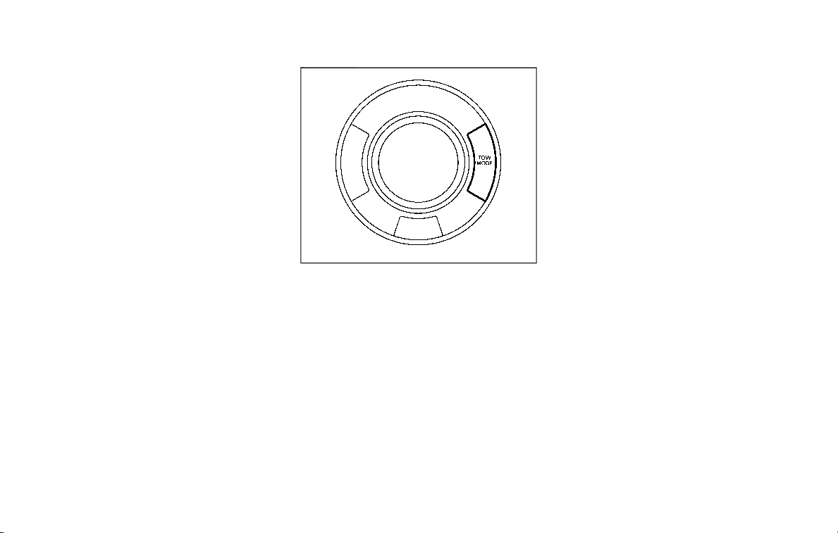
5-126 Starting and driving
Turn the wheels toward the side of
the road so the vehicle will move away
from the center of the road if it moves.
4. Push the ignition switch to the OFF
position.
SIC4474
The TOW MODE should be used when
pulling a heavy trailer or hauling a heavy
load. Driving the vehicle in the TOW MODE
with no trailer/load or light trailer/light
load will not cause any damage. However,
fuel economy may be reduced, and the
transmission/engine driving characteris-
tics may feel unusual.
Push the TOW MODE switch to activate
TOW MODE. The indicator light on the
TOW MODE switch illuminates when the
TOW MODE is selected. Push the TOW
MODE switch again to turn the TOW
MODE OFF.
TOW MODE is automatically canceled
when the ignition switch is placed in the
OFF position.
TOW MODE
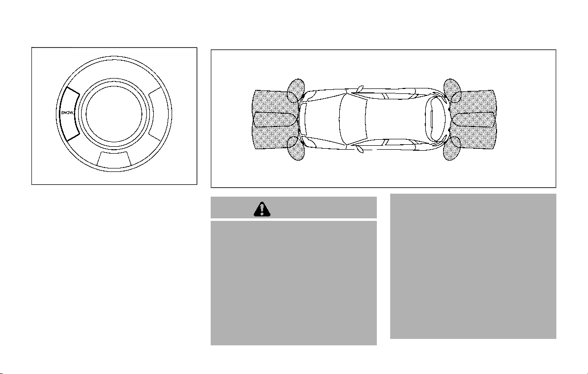
SIC4454
For driving or starting the vehicle on
snowy roads or slippery areas, turn the
SNOW mode on.
To turn the SNOW mode on, push the
SNOW mode switch. The SNOW mode
indicator light on the meter panel will
illuminate. When the SNOW mode is
activated, engine output is controlled to
avoid wheel spin.
To turn the SNOW mode off, push the
switch and the indicator on the meter
panel will turn off. Turn the SNOW mode
off for normal driving and fuel economy.
SSD0622
WARNING
. The sonar system is a conveni-
ence but it is not a substitute for
proper parking. Always look
around and check that it is safe
to do so before parking. Always
move slowly.
. Read and understand the limita-
tions of the sonar system as
contained in this section. Incle-
ment weather may affect the
function of the sonar system; this
may include reduced perfor-
mance or a false activation.
. This system is not designed to
prevent contact with small or
moving objects.
. The system is designed as an aid
to the driver in detecting large
stationary objects to help avoid
damaging the vehicle. The sys-
tem will not detect small objects
below the bumper, and may not
detect objects that are too close
to the bumper or on the ground.
. If your vehicle sustains damage
to the bumper fascia, leaving it
misaligned or bent, the sensing
zone may be altered causing in-
Starting and driving 5-127
SNOW MODE SONAR SYSTEM (if so equipped)
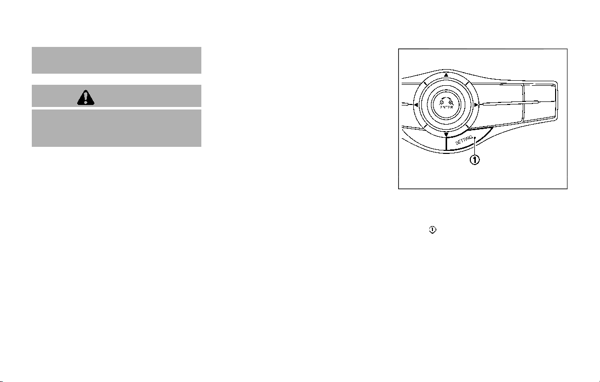
5-128 Starting and driving
accurate measurement of obsta-
cles or false alarms.
CAUTION
Keep the interior of the vehicle as
quiet as possible to hear the tone
clearly.
The sonar system sounds a tone to warn
the driver of obstacles near the bumper.
When the “Interrupt Display” is turned on
in the Sonar settings, the sonar indicator
will also appear in the center display. (See
“Sonar indicator” (P.5-129).) The system
detects front obstacles when the shift
lever is in the D (Drive) position or N
(Neutral) position. The system detects
both front and rear obstacles when the
shift lever is in the R (Reverse) position.
The system may not detect objects at
speeds above 6 MPH (10 km/h) and may
not detect certain angular or moving
objects.
The sonar system detects obstacles up to
3.9 ft (1.2 m) from the bumper with a
decreased coverage area at the outer
corners of the bumper. Refer to the
illustration for approximate zone cover-
age areas. As you move closer to the
obstacle, the rate of the tone increases.
When the obstacle is less than 11.8 in (30
cm) away, the tone will sound continu-
ously.
Keep the corner/center sensors (located
on the bumper fascia) free from snow, ice
and large accumulations of dirt (do not
clean the sensors with sharp objects). If
the sensors are covered, it will affect the
accuracy of the sonar system.
The sensitivity level of the corner/center
sensors can be adjusted (higher or lower)
in the Sonar settings on the center dis-
play. (See “Sonar settings” (P.5-128).)
The intermittent tone will stop in 3
seconds when an obstacle is detected
by only the corner sensor and the dis-
tance does not change.
JVS1043X
SONAR SETTINGS
To set up the sonar function to your
preferred settings, push the SETTING
button
, select the “Camera/Sonar” key
and then select the “Sonar” key on the
center display.
Sonar:
When this item is turned on, the front and
rear sonar is activated. When this item is
turned off (indicator turns off), the front
and rear sonar is deactivated.
FR sensor only:
When this item is turned on, only the front
sonar is activated.
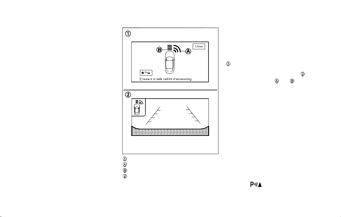
Interrupt Display:
When this item is turned on, the sonar
display will interrupt the current view to
indicate that the obstacles are around
the vehicle.
Sonar Sensitivity:
Adjust the sensitivity level of the sonar.
Sonar Volume:
Adjust the tone volume of the sonar.
JVS1085X
Sonar display
Corner sensor indicator
Center sensor indicator
RearView Monitor display
SONAR INDICATOR
With the “Interrupt Display” turned on in
the Sonar settings, when the corner/
center sensors detect obstacles near the
bumper, a tone will sound and the sonar
indicator will appear in the center display
. When the RearView Monitor is dis-
played, the sonar indicator will appear in
the upper corner of the display
.
The sonar indicators
and
indicate the
position of the object and the distance to
the object with its color and rate of
blinking.
When an object is detected, the indicator
(green) appears and blinks (the tone
sounds intermittently). When the vehicle
moves closer to the object, the color of
the indicator turns yellow and the rate of
blinking increases (the rate of the tone
increases). When the bumper is very close
to the object, less than 11.8 in (30 cm)
away, the indicator stops blinking and
turns red (the tone sounds continuously).
When the RearView Monitor is dis-
played, the colors of the sonar indicator
and the distance guide lines in the rear
view indicate different distances to the
object.
When the
is touched, the sonar will
be turned off temporarily.
The sonar indicator can be turned off in
Starting and driving 5-129

5-130 Starting and driving
the Sonar settings on the center display.
(See “Sonar settings” (P.5-128).) When the
sonar indicator is off, only a tone sounds
when the sonar detect obstacles.
WARNING
If the engine is not running or is
turned off while driving, the power
assist for the steering will not work.
Steering will be harder to operate.
The power assisted steering uses a hy-
draulic pump, driven by the engine, to
assist steering.
If the engine stops or the drive belt
breaks, you will still have control of the
vehicle. However, much greater steering
effort is needed, especially in sharp turns
and at low speeds.
BRAKING PRECAUTIONS
The brake system has two separate
hydraulic circuits. If one circuit malfunc-
tions, you will still have braking ability at
two wheels.
You may feel a small click and hear a
sound when the brake pedal is fully
depressed slowly. This is not a malfunc-
tion and indicates that the brake assist
mechanism is operating properly.
Hydraulically-assisted brakes
The hydraulically-assisted brake system is
designed to use a hydraulic pump driven
electrically, to assist braking. If the engine
stops, you can stop the vehicle by de-
pressing the foot brake pedal. However,
greater foot pressure on the foot brake
pedal will be required to stop the vehicle.
The stopping distance will be longer.
Wet brakes
When the vehicle is washed or driven
through water, the brakes may get wet.
As a result, your braking distance will be
longer and the vehicle may pull to one
side during braking.
To dry brakes, drive the vehicle at a safe
speed while lightly tapping the brake
pedal to heat-up the brakes. Do this until
the brakes return to normal. Avoid driving
the vehicle at high speeds until the brakes
POWER STEERING BRAKE SYSTEM

function correctly.
PARKING BRAKE BREAK-IN
Break in the parking brake shoes when-
ever the stopping effect of the parking
brake is weakened or whenever the
parking brake shoes and/or drums/ro-
tors are replaced, in order to assure the
best braking performance.
This procedure is described in the vehicle
service manual. It is recommended you
visit a NISSAN dealer for this service.
Using the brakes
Avoid resting your foot on the brake
pedal while driving. This will cause over-
heating of the brakes, wearing out the
brake and pads faster and reduce gas
mileage.
To help save the brakes and to prevent
the brakes from overheating, reduce
speed and downshift to a lower gear
before going down a slope or long grade.
Overheated brakes may reduce braking
performance and could result in loss of
vehicle control.
WARNING
. While driving on a slippery sur-
face, be careful when braking,
accelerating or downshifting.
Abrupt braking or accelerating
could cause the wheels to skid
and result in an accident.
. If the engine is not running or is
turned off while driving, the
power assist for the brakes will
not work. Braking will be harder.
BRAKE ASSIST
When the force applied to the brake pedal
exceeds a certain level, the Brake Assist is
activated generating greater braking
force than a conventional brake booster
even with light pedal force.
WARNING
The Brake Assist is only an aid to
assist braking operation and is not a
collision warning or avoidance de-
vice. It is the driver’s responsibility to
stay alert, drive safely and be in
control of the vehicle at all times.
ANTI-LOCK BRAKING SYSTEM (ABS)
WARNING
. The Anti-lock Braking System
(ABS) is a sophisticated device,
but it cannot prevent accidents
resulting from careless or dan-
gerous driving techniques. It can
help maintain vehicle control dur-
ing braking on slippery surfaces.
Remember that stopping dis-
tances on slippery surfaces will
be longer than on normal sur-
Starting and driving 5-131
BRAKE ASSIST

5-132 Starting and driving
faces even with ABS. Stopping
distances may also be longer on
rough, gravel or snow covered
roads, or if you are using tire
chains. Always maintain a safe
distance from the vehicle in front
of you. Ultimately, the driver is
responsible for safety.
. Tire type and condition may also
affect braking effectiveness.
— When replacing tires, install
the specified size of tires on
all four wheels.
— When installing a spare tire,
make sure that it is the proper
size and type as specified on
the Tire and Loading Informa-
tion label. See “Tire and load-
ing information label” (P.10-
12).
— For detailed information, see
“Wheels and tires” (P.8-30).
The Anti-lock Braking System (ABS) con-
trols the brakes so the wheels do not lock
during hard braking or when braking on
slippery surfaces. The system detects the
rotation speed at each wheel and varies
the brake fluid pressure to prevent each
wheel from locking and sliding. By pre-
venting each wheel from locking, the
system helps the driver maintain steering
control and helps to minimize swerving
and spinning on slippery surfaces.
Using the system
Depress the brake pedal and hold it down.
Depress the brake pedal with firm steady
pressure, but do not pump the brakes.
The ABS will operate to prevent the
wheels from locking up. Steer the vehicle
to avoid obstacles.
WARNING
Do not pump the brake pedal. Doing
so may result in increased stopping
distances.
Self-test feature
The ABS includes electronic sensors, elec-
tric pumps, hydraulic solenoids and a
computer. The computer has a built-in
diagnostic feature that tests the system
each time you start the engine and move
the vehicle at a low speed in forward or
reverse. When the self-test occurs, you
may hear a “clunk” noise and/or feel a
pulsation in the brake pedal. This is
normal and does not indicate a malfunc-
tion. If the computer senses a malfunc-
tion, it switches the ABS off and
illuminates the ABS warning light on the
instrument panel. The brake system then
operates normally, but without anti-lock
assistance.
If the ABS warning light illuminates during
the self-test or while driving, have the
vehicle checked. It is recommended you
visit a NISSAN dealer for this service.
Normal operation
The ABS operates at speeds above 3 to 6
MPH (5 to 10 km/h). The speed varies
according to road conditions.
When the ABS senses that one or more
wheels are close to locking up, the
actuator rapidly applies and releases
hydraulic pressure. This action is similar
to pumping the brakes very quickly. You
may feel a pulsation in the brake pedal
and hear a noise from under the hood or
feel a vibration from the actuator when it
is operating. This is normal and indicates
that the ABS is operating properly. How-
ever, the pulsation may indicate that road
conditions are hazardous and extra care
is required while driving.

The Vehicle Dynamic Control (VDC) sys-
tem uses various sensors to monitor
driver inputs and vehicle motion. Under
certain driving conditions, the VDC sys-
tem helps to perform the following func-
tions.
. Controls brake pressure to reduce
wheel slip on one slipping drive wheel
so power is transferred to a non
slipping drive wheel on the same axle.
. Controls brake pressure and engine
output to reduce drive wheel slip
based on vehicle speed (traction con-
trol function).
. Controls brake pressure at individual
wheels and engine output to help the
driver maintain control of the vehicle
in the following conditions:
— understeer (vehicle tends to not
follow the steered path despite
increased steering input)
— oversteer (vehicle tends to spin due
to certain road or driving condi-
tions).
The VDC system can help the driver to
maintain control of the vehicle, but it
cannot prevent loss of vehicle control in
all driving situations.
When the VDC system operates, the VDC
warning light
in the instrument panel
flashes so note the following:
. The road may be slippery or the
system may determine some action
is required to help keep the vehicle on
the steered path.
. You may feel a pulsation in the brake
pedal and hear a noise or vibration
from under the hood. This is normal
and indicates that the VDC system is
working properly.
. Adjust your speed and driving to the
road conditions.
If a malfunction occurs in the system, the
VDC warning light
illuminates in the
instrument panel. The VDC system auto-
matically turns off.
The VDC OFF switch is used to turn off the
VDC system. The VDC off indicator
illuminates to indicate the VDC system is
off. When the VDC switch is used to turn
off the system, the VDC system still
operates to prevent one drive wheel from
slipping by transferring power to a non
slipping drive wheel. The VDC warning
light
flashes if this occurs. All other
VDC functions are off, and the VDC
warning light
will not flash. The VDC
system is automatically reset to on when
the ignition switch is placed in the OFF
position then back to the ON position.
When the 4L position is selected with the
4WD shift switch, the VDC system is
disabled and the VDC off indicator light
illuminates (for 4WD models).
See “Vehicle Dynamic Control (VDC) warn-
ing light” (P.2-17) and “Vehicle Dynamic
Control (VDC) off indicator light” (P.2-20).
The computer has a built-in diagnostic
feature that tests the system each time
you start the engine and move the vehicle
forward or in reverse at a slow speed.
When the self-test occurs, you may hear a
“clunk” noise and/or feel a pulsation in the
brake pedal. This is normal and is not an
indication of a malfunction.
WARNING
. The VDC system is designed to
help improve driving stability but
does not prevent accidents due
to abrupt steering operation at
high speeds or by careless or
dangerous driving techniques.
Reduce vehicle speed and be
especially careful when driving
and cornering on slippery sur-
faces and always drive carefully.
. Do not modify the vehicle’s sus-
pension. If suspension parts such
as shock absorbers, struts,
springs, stabilizer bars, bushings
and wheels are not NISSAN re-
commended for your vehicle or
Starting and driving 5-133
VEHICLE DYNAMIC CONTROL (VDC) SYSTEM
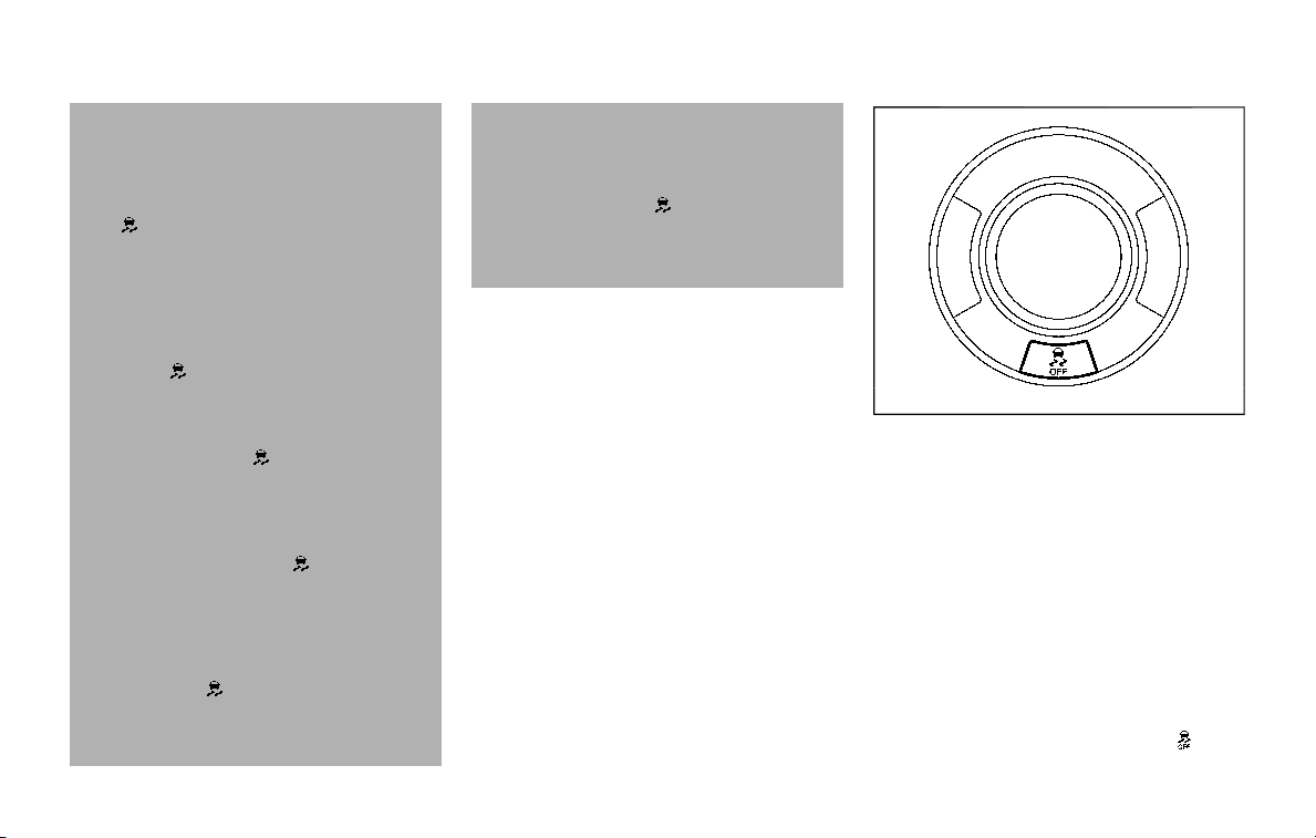
5-134 Starting and driving
are extremely deteriorated, the
VDC system may not operate
properly. This could adversely
affect vehicle handling perfor-
mance, and the VDC warning light
may illuminate.
. If brake related parts such as
brake pads, rotors and calipers
are not NISSAN recommended or
are extremely deteriorated, the
VDC system may not operate
properly and the VDC warning
light
may illuminate.
. If engine control related parts are
not NISSAN recommended or are
extremely deteriorated, the VDC
warning light
may illuminate.
. When driving on extremely in-
clined surfaces such as higher
banked corners, the VDC system
may not operate properly and the
VDC warning light
may illumi-
nate. Do not drive on these types
of roads.
. When driving on an unstable sur-
face such as a turntable, ferry,
elevator or ramp, the VDC warn-
ing light
may illuminate. This
is not a malfunction. Restart the
engine after driving onto a stable
surface.
. If wheels or tires other than the
NISSAN recommended ones are
used, the VDC system may not
operate properly and the VDC
warning light
may illuminate.
. The VDC system is not a substi-
tute for winter tires or tire chains
on a snow covered road.
SIC4455
VEHICLE DYNAMIC CONTROL (VDC)
OFF SWITCH
The vehicle should be driven with the
Vehicle Dynamic Control (VDC) system ON
for most driving conditions.
When the vehicle is stuck in mud or snow,
the VDC system reduces the engine out-
put to reduce wheel spin. The engine
speed will be reduced even if the accel-
erator is depressed to the floor. If max-
imum engine power is needed to free a
stuck vehicle, turn the VDC system off.
To turn off the Vehicle Dynamic Control
(VDC) system, push the VDC OFF switch.
The VDC off indicator light
will
illuminate.

Push the VDC OFF switch again or restart
the engine to turn ON the system.
FREEING A FROZEN DOOR LOCK
To prevent a door lock from freezing,
apply deicer through the key hole. If the
lock becomes frozen, heat the key before
inserting it into the key hole or use the
Intelligent Key system.
ANTIFREEZE
In the winter when it is anticipated that
the outside temperature will drop below
32°F (0°C), check antifreeze to assure
proper winter protection. For additional
information, see “Engine cooling system”
(P.8-4).
BATTERY
If the battery is not fully charged during
extremely cold weather conditions, the
battery fluid may freeze and damage the
battery. To maintain maximum efficiency,
the battery should be checked regularly.
For additional information, see “Battery”
(P.8-11).
DRAINING OF COOLANT WATER
If the vehicle is to be left outside without
antifreeze, drain the cooling system, in-
cluding the engine block. Refill before
operating the vehicle. For details, see
“Engine cooling system” (P.8-4).
TIRE EQUIPMENT
SUMMER tires have a tread designed to
provide superior performance on dry
pavement. However, the performance of
these tires will be substantially reduced in
snowy and icy conditions. If you operate
your vehicle on snowy or icy roads,
NISSAN recommends the use of MUD &
SNOW or ALL SEASON tires on all four
wheels. It is recommended you consult a
NISSAN dealer for the tire type, size, speed
rating and availability information.
For additional traction on icy roads,
studded tires may be used. However,
some U.S. states and Canadian provinces
prohibit their use. Check local, state and
provincial laws before installing studded
tires.
Skid and traction capabilities of
studded snow tires, on wet or dry
surfaces, may be poorer than that of
non-studded snow tires.
Tire chains may be used. For details, see
“Tire chains” (P.8-37).
Starting and driving 5-135
COLD WEATHER DRIVING

5-136 Starting and driving
For four-wheel drive
If you install snow tires, they must also be
the same size, brand, construction and
tread pattern on all four wheels.
SPECIAL WINTER EQUIPMENT
It is recommended that the following
items be carried in the vehicle during
winter:
. A scraper and stiff-bristled brush to
remove ice and snow from the win-
dows and wiper blades.
. A sturdy, flat board to be placed under
the jack to give it firm support.
. A shovel to dig the vehicle out of
snowdrifts.
. Extra window washer fluid to refill the
reservoir tank.
DRIVING ON SNOW OR ICE
WARNING
. Wet ice (32°F, 0°C and freezing
rain), very cold snow or ice can be
slick and very hard to drive on.
The vehicle will have much less
traction or “grip” under these
conditions. Try to avoid driving
on wet ice until the road is salted
or sanded.
. Whatever the condition, drive
with caution. Accelerate and slow
down with care. If accelerating or
downshifting too fast, the drive
wheels will lose even more trac-
tion.
. Allow more stopping distance
under these conditions. Braking
should be started sooner than on
dry pavement.
. Allow greater following distances
on slippery roads.
. Watch for slippery spots (glare
ice). These may appear on an
otherwise clear road in shaded
areas. If a patch of ice is seen
ahead, brake before reaching it.
Try not to brake while on the ice,
and avoid any sudden steering
maneuvers.
. Do not use the cruise control on
slippery roads.
. Snow can trap dangerous ex-
haust gases under your vehicle.
Keep snow clear of the exhaust
pipe and from around your vehi-
cle.
ENGINE BLOCK HEATER (if so
equipped)
Engine block heaters are used to assist in
cold temperature starting.
The engine block heater should be used
when the outside temperature is 20°F
(−7°C) or lower.
To use the engine block heater
1. Turn the engine off.
2. Open the hood and unwrap the en-
gine block heater cord.
3. Plug the engine block heater cord into
a grounded 3-wire, 3-pronged exten-
sion cord.
4. Plug the extension cord into a Ground
Fault Interrupt (GFI) protected,
grounded 110-volt AC (VAC) outlet.
5. The engine block heater must be
plugged in for at least 2 - 4 hours,
depending on outside temperatures,
to properly warm the engine coolant.
Use an appropriate timer to turn the
engine block heater on.
6. Before starting the engine, unplug and
properly store the cord to keep it
away from moving parts.

WARNING
. Do not use your engine block
heater with an ungrounded elec-
trical system or a 2-pronged
adapter. You can be seriously
injured by an electrical shock if
you use an ungrounded connec-
tion.
. Disconnect and properly store the
engine block heater cord before
starting the engine. Damage to
the cord could result in an elec-
trical shock and can cause ser-
ious injury.
. Use a heavy-duty 3-wire, 3-
pronged extension cord rated
for at least 10A. Plug the exten-
sion cord into a Ground Fault
Interrupt (GFI) protected,
grounded 110-VAC outlet. Failure
to use the proper extension cord
or a grounded outlet can result in
a fire or electrical shock and
cause serious personal injury.
Starting and driving 5-137

5-138 Starting and driving
MEMO

6 In case of emergency
Hazard warning flasher switch ......................................... 6-2
Roadside assistance program ........................................... 6-2
Emergency engine shut off .................................................. 6-3
Flat tire .................................................................................................. 6-3
Tire Pressure Monitoring System (TPMS) .......... 6-3
Changing a flat tire .............................................................. 6-4
Jump starting ............................................................................... 6-12
Push starting ................................................................................. 6-14
If your vehicle overheats .................................................... 6-14
Towing your vehicle ............................................................... 6-16
Towing recommended by NISSAN ..................... 6-17
Vehicle recovery (freeing a stuck vehicle) ...... 6-19
Four-Wheel Drive (4WD) manual shifting
(4WD models) ............................................................................... 6-20
When 4WD warning light illuminates ............... 6-20
Operating procedure ..................................................... 6-21
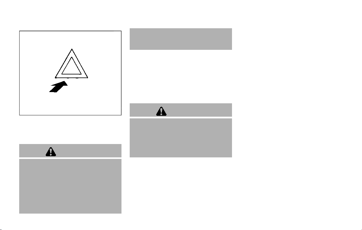
6-2 In case of emergency
SIC2574
Push the switch on to warn other drivers
when you must stop or park under
emergency conditions. All turn signal
lights will flash.
WARNING
. If stopping for an emergency, be
sure to move the vehicle well off
the road.
. Do not use the hazard warning
flashers while moving on the
highway unless unusual circum-
stances force you to drive so
slowly that your vehicle might
become a hazard to other traffic.
. Turn signals do not work when
the hazard warning flasher lights
are on.
The flasher can be actuated with the
ignition switch in any position.
When an impact that could activate the
supplemental air bags is detected, the
hazard warning flasher lights blink auto-
matically. If the hazard warning flasher
switch is pushed twice, the hazard warn-
ing flashers will turn off.
WARNING
Do not turn the hazard warning
flasher switch to off until you can
make sure that it is safe to do so.
Also, the hazard flasher warning may
not blink automatically depending
on the force of impact.
Some state laws may prohibit the use of
the hazard warning flasher switch while
driving.
In the event of a roadside emergency,
Roadside Assistance Service is available
to you. Please refer to your Warranty
Information Booklet (U.S.) or Warranty &
Roadside Assistance Information Booklet
(Canada) for details.
HAZARD WARNING FLASHER SWITCH
ROADSIDE ASSISTANCE PROGRAM

To shut off the engine in an emergency
situation while driving, perform the fol-
lowing procedure:
. Rapidly push the push-button ignition
switch 3 consecutive times in less
than 1.5 seconds, or
. Push and hold the push-button igni-
tion switch for more than 2 seconds.
TIRE PRESSURE MONITORING SYS-
TEM (TPMS)
This vehicle is equipped with the Tire
Pressure Monitoring System (TPMS). It
monitors tire pressure of all tires except
the spare. When the low tire pressure
warning light is lit and the CHECK TIRE
PRESSURE warning appears in the vehicle
information display, one or more of your
tires is significantly under-inflated. If the
vehicle is being driven with low tire
pressure, the TPMS will activate and warn
you of it by the low tire pressure warning
light. This system will activate only when
the vehicle is driven at speeds above 16
MPH (25 km/h). For more details, see “Low
tire pressure warning light” (P.2-15) and
“Tire Pressure Monitoring System (TPMS)”
(P.5-5).
WARNING
. If the low tire pressure warning
light illuminates or Low Pressure
information is displayed on the
monitor screen while driving,
avoid sudden steering maneu-
vers or abrupt braking, reduce
vehicle speed, pull off the road
to a safe location and stop the
vehicle as soon as possible. Driv-
ing with under-inflated tires may
permanently damage the tires
and increase the likelihood of tire
failure. Serious vehicle damage
could occur and may lead to an
accident and could result in ser-
ious personal injury. Check the
tire pressure for all four tires.
Adjust the tire pressure to the
recommended COLD tire pressure
shown on the Tire and Loading
Information label to turn the low
tire pressure warning light OFF. If
the light still illuminates while
driving after adjusting the tire
pressure, a tire may be flat. If
you have a flat tire, replace it with
a spare tire as soon as possible.
. Since the spare tire is not
equipped with the TPMS, when a
spare tire is mounted or a wheel
is replaced, the TPMS will not
function and the low tire pressure
warning light will flash for ap-
proximately 1 minute. The light
will remain on after 1 minute.
Have your tires replaced and/or
TPMS system reset as soon as
possible. It is recommended you
visit a NISSAN dealer for these
services.
. Replacing tires with those not
originally specified by NISSAN
In case of emergency 6-3
EMERGENCY ENGINE SHUT OFF FLAT TIRE
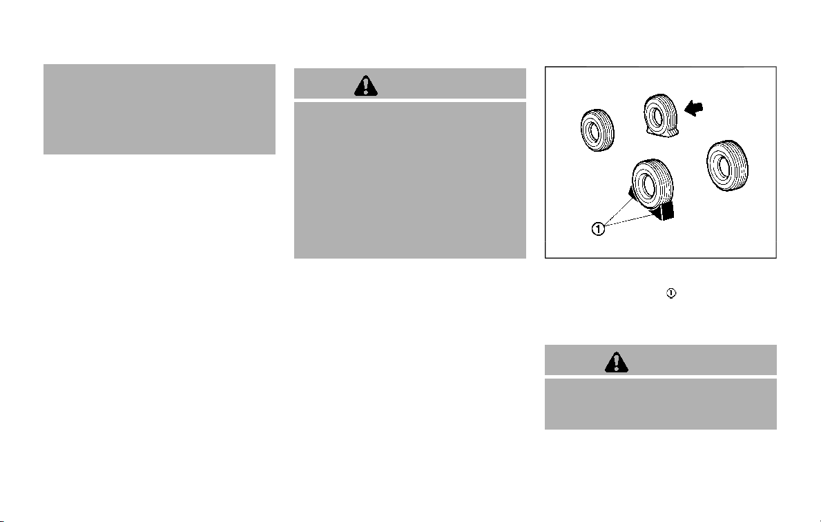
6-4 In case of emergency
could affect the proper operation
of the TPMS.
. Do not inject any tire liquid or
aerosol tire sealant into the tires,
as this may cause a malfunction
of the tire pressure sensors.
CHANGING A FLAT TIRE
If you have a flat tire, follow the instruc-
tions below.
Stopping the vehicle
1. Safely move the vehicle off the road
and away from traffic.
2. Turn on the hazard warning flashers.
3. Park on a level surface and apply the
parking brake. Move the shift lever to
the P (Park) position.
4. Turn off the engine.
5. Raise the hood to warn other traffic,
and to signal professional road assis-
tance personnel that you need assis-
tance.
6. Have all passengers get out of the
vehicle and stand in a safe place, away
from traffic and clear of the vehicle.
WARNING
. Make sure the parking brake is
securely applied and the auto-
matic transmission is in the P
(Park) position.
. Never change tires when the ve-
hicle is on a slope, ice or slippery
areas. This is hazardous.
. Never change tires if oncoming
traffic is close to your vehicle.
Wait for professional road assis-
tance.
MCE0001A
Blocking wheels
Place suitable blocks at both the front
and back of the wheel diagonally oppo-
site the flat tire to prevent the vehicle
from moving when it is jacked up.
WARNING
Be sure to block the wheel as the
vehicle may move and result in
personal injury.
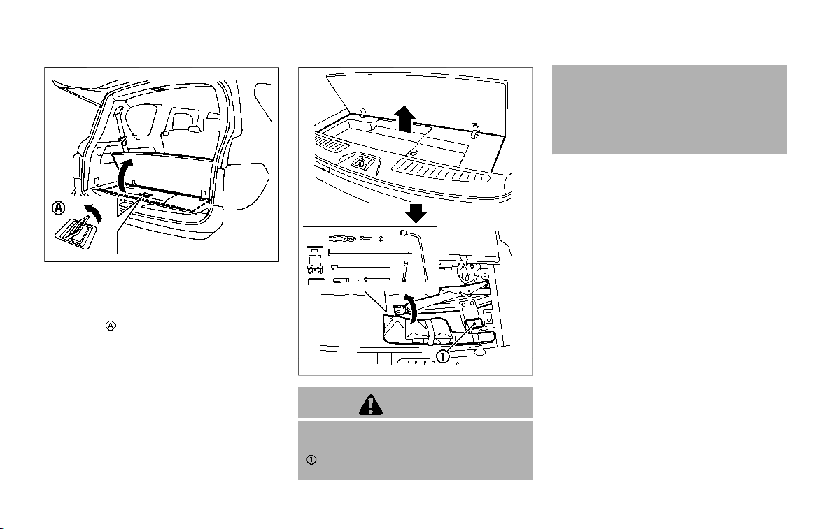
JVE0219X
Getting the spare tire and tools
1. Open the liftgate.
2. Raise the cargo floor board using the
handle
.
JVE0422X
WARNING
When removing jacking tools, be
sure the rubber sound suppressor
, used to control jack stand from
rattling against metal, is not at-
tached to the jacking tool. If rubber
sound suppressor remains on jack
when vehicle is being jacked up, the
vehicle will be unstable and may fall
off jack stand causing serious injury
of death.
3. Remove the cargo floor cover.
4. Remove the jacking tools.
In case of emergency 6-5

6-6 In case of emergency
JVE0423X
5. Securely screw to connect the T-
shaped end of the jack rod and the
extension bar
as illustrated.
6. Fit the square end of the jack rod into
the square hole of the wheel nut
wrench to form a handle
.
7. Locate the oval opening above the
middle of the rear bumper.
8. Place the T-shaped end of the jack rod
through the opening and direct it
towards the spare wheel winch as-
sembly, located directly above the
spare wheel.
SCE0916
CAUTION
Do not insert the jack rod straight as
it is designed to be inserted at an
angle as shown.
9. Seat the T-shaped end of the jack rod
into the T-shaped opening of the
spare wheel winch. Apply pressure to
keep the jack rod engaged in the
spare wheel winch and turn the jack
rod counterclockwise to lower the
spare wheel.
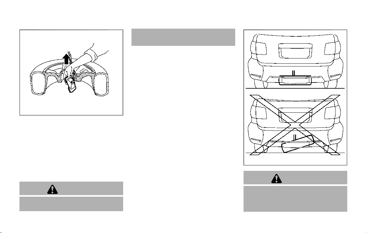
SCE0377
10. Once the spare wheel is completely
lowered, remove the jack rod and
reach under the vehicle to remove
the hanging plate.
11. Carefully slide the spare wheel from
under the rear of the vehicle.
After preparing the spare tire, to remove
the rod, pull out the rod while moving the
rod to the right and left with the screw of
the extension facing the side.
CAUTION
When storing the wheel, make sure
that the hanging plate is in the
center of the wheel and then lift it
up into the storage area.
JVE0349X
CAUTION
When storing the wheel, be sure to
mount the wheel horizontally. Secur-
ing the wheel that is in a tilted
position as illustrated may cause
In case of emergency 6-7
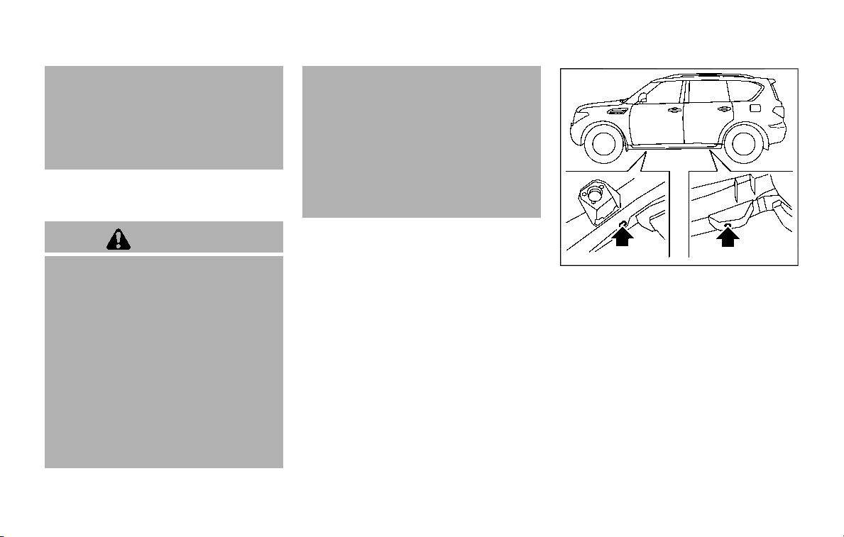
6-8 In case of emergency
looseness and dropping of the wheel
while driving. Lower the wheel on the
ground again, and make sure that
the hanging plate is properly set.
Hang the wheel again and make sure
that the wheel is held horizontally,
then store the wheel.
Jacking up the vehicle and remov-
ing the damaged tire
WARNING
. Never get under the vehicle while
it is supported only by the jack. If
it is necessary to work under the
vehicle, support it with safety
stands.
. Use only the jack provided with
your vehicle to lift the vehicle. Do
not use the jack provided with
your vehicle on other vehicles.
The jack is designed for lifting
only your vehicle during a tire
change.
. Use the correct jack-up points.
Never use any other part of the
vehicle for jack support.
. Never jack up the vehicle more
than necessary.
. Never use blocks on or under the
jack.
. Do not start or run the engine
while vehicle is on the jack, as it
may cause the vehicle to move.
. Do not allow passengers to stay
in the vehicle while it is on the
jack.
Carefully read the caution label at-
tached to the jack body and the follow-
ing instructions.
SCE0875
Jack-up point
1. Place the jack directly under the jack-
up points as illustrated.
The jack should be used on level firm
ground.
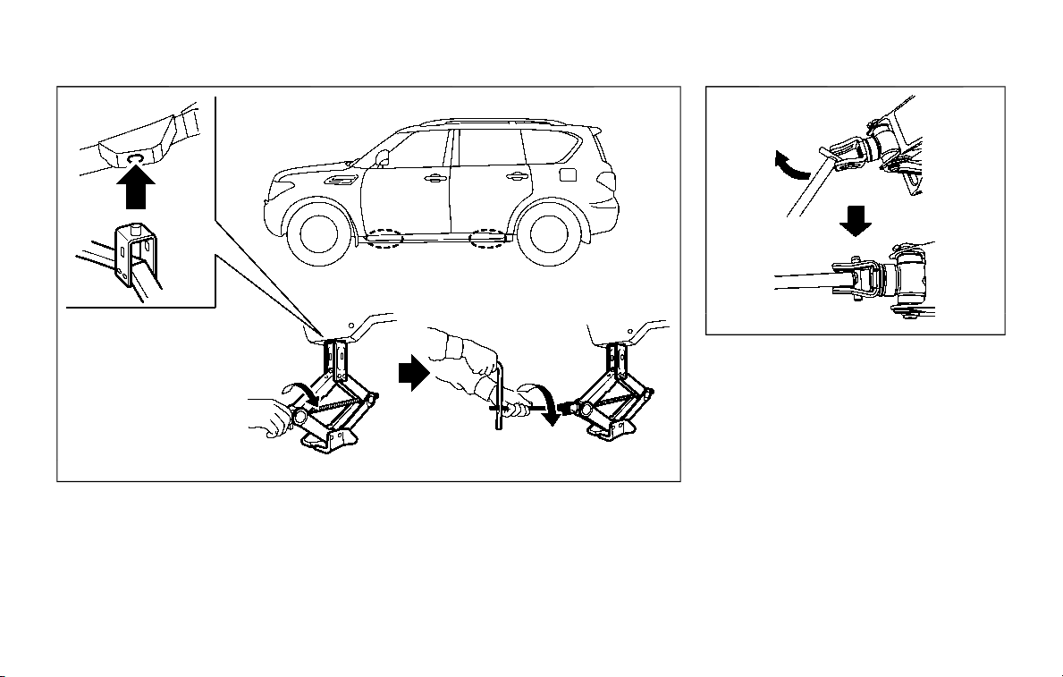
SCE0876
2. Loosen each wheel nut one or two
turns by turning counterclockwise
with the wheel nut wrench. Do not
remove the wheel nuts until the tire
is off the ground.
NCE130
3. Install the assembled jack rod into the
jack as shown.
4. Carefully raise the vehicle until the
clearance between the tire and
ground is achieved.
5. To lift the vehicle, securely hold the
jack lever and rod with both hands
and turn the jack lever.
NOTE:
Before jacking up the vehicle, make
sure the ignition switch is placed in
the OFF position. If the vehicle is lifted
up with the engine running, the auto-
leveling suspension will become dis-
abled after 120 seconds. To reset the
auto-leveling suspension, cycle the
In case of emergency 6-9
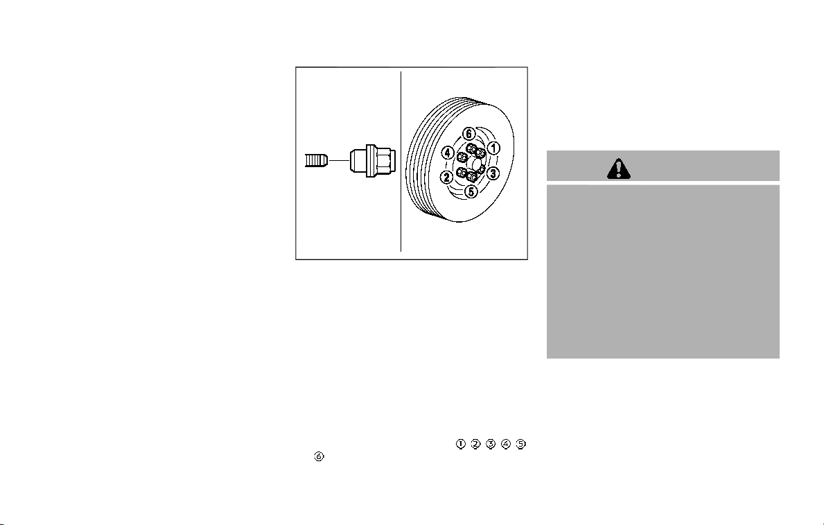
6-10 In case of emergency
ignition switch ON/OFF one time.
SCE0910
Installing the spare tire
The full-size temporary use only spare
tire (if so equipped) is designed for
emergency use. (See specific instruc-
tions under the heading “Wheels and
tires” (P.8-30).)
1. Clean any mud or dirt from the sur-
face between the wheel and hub.
2. Carefully put the spare tire on and
tighten the wheel nuts finger tight.
3. With the wheel nut wrench, tighten
wheel nuts alternately and evenly in
the sequence illustrated (
, , , , ,
) until they are tight.
4. Lower the vehicle slowly until the tire
touches the ground. Then, with the
wheel nut wrench, tighten the wheel
nuts securely in the sequence as
illustrated. Lower the vehicle comple-
tely.
WARNING
. Incorrect wheel nuts or impro-
perly tightened wheel nuts can
cause the wheel to become loose
or come off. This could cause an
accident.
. Do not use oil or grease on the
wheel studs or nuts. This could
cause the nuts to become loose.
. Retighten the wheel nuts when
the vehicle has been driven for
600 miles (1,000 km) (also in
cases of a flat tire, etc.).
.
As soon as possible, tighten the
wheel nuts to the specified torque
with a torque wrench.
Wheel nut tightening torque:
98 ft-lb (133 N·m)
The wheel nuts must be kept
tightened to specification at all
times. It is recommended that
wheel nuts be tightened to speci-

fications at each lubrication inter-
val.
.
Adjust tire pressure to the COLD
pressure.
COLD pressure:
After the vehicle has been parked
for three hours or more or driven
less than 1 mile (1.6 km).
COLD tire pressures are shown on
the Tire and Loading Information
label affixed to the driver side
center pillar.
After adjusting tire pressure to the COLD
tire pressure, the display of the tire
pressure information may show higher
pressure than the COLD tire pressure
after the vehicle has been driven more
than 1 mile (1.6 km). This is because the
tire pressurizes as the tire temperature
rises. This does not indicate a system
malfunction.
Stowing the damaged tire and
tools
1. Securely store the damaged tire, jack
and tools in the storage area.
2. Close the cargo floor cover.
3. Replace the cargo floor board.
4. Close the liftgate.
WARNING
. Always make sure that the spare
tire and jacking equipment are
properly secured after use. Such
items can become dangerous
projectiles in an accident or sud-
den stop.
. The full-size temporary use only
spare tire (if so equipped) is de-
signed for emergency use. (See
specific instructions under the
heading “Wheels and tires” (P.8-
30).)
In case of emergency 6-11

6-12 In case of emergency
To start your engine with a booster
battery, the instructions and precautions
below must be followed.
WARNING
. If done incorrectly, jump starting
can lead to a battery explosion,
resulting in severe injury or
death. It could also damage your
vehicle.
. Explosive hydrogen gas is always
present in the vicinity of the
battery. Keep all sparks and
flames away from the battery.
. Do not allow battery fluid to come
into contact with eyes, skin,
clothing or painted surfaces. Bat-
tery fluid is a corrosive sulphuric
acid solution which can cause
severe burns. If the fluid should
come into contact with anything,
immediately flush the contacted
area with water.
. Keep the battery out of the reach
of children.
. The booster battery must be
rated at 12 volts. Use of an im-
properly rated battery can da-
mage your vehicle.
. Whenever working on or near a
battery, always wear suitable eye
protectors (for example, goggles
or industrial safety spectacles)
and remove rings, metal bands,
or any other jewelry. Do not lean
over the battery when jump start-
ing.
. Do not attempt to jump start a
frozen battery. It could explode
and cause serious injury.
. Your vehicle has an automatic
engine cooling fan. It could come
on at any time. Keep hands and
other objects away from it.
JUMP STARTING

JVE0485X
WARNING
Always follow the instructions below.
Failure to do so could result in
damage to the charging system and
cause personal injury.
1. Remove the engine compartment
cover, if necessary. See “Engine com-
partment check locations” (P.8-3).
2. If the booster battery is in another
vehicle
, position the two vehicles (
and ) to bring their batteries into
close proximity to each other.
Do not allow the two vehicles to
touch.
3. Apply parking brake. Move the shift
lever to the P (Park) position. Switch
off all unnecessary electrical systems
(light, heater, air conditioner, etc.).
4. Remove vent caps on the battery (if so
equipped). Cover the battery with a
firmly wrung out moist cloth
to
reduce explosion hazard.
5. Connect jumper cables in the se-
quence as illustrated (
? ? ?
).
CAUTION
. Always connect positive (+) to
positive (+) and negative (−) to
body ground (as illustrated) —
not to the battery.
. Make sure the jumper cables do
not touch moving parts in the
engine compartment and that
clamps do not contact any other
metal.
6. Start the engine of the booster vehicle
and let it run for a few minutes.
7. Keep the engine speed of the booster
vehicle
at about 2,000 rpm, and
start the engine of the vehicle being
jump started
.
CAUTION
Do not keep the starter motor en-
gaged for more than 10 seconds. If
the engine does not start right away,
place the ignition switch in the OFF
position and wait 10 seconds before
trying again.
In case of emergency 6-13

6-14 In case of emergency
8. After starting your engine, carefully
disconnect the negative cable and
then the positive cable (
? ?
? ).
9. Replace the vent caps (if so equipped).
Be sure to dispose of the cloth used to
cover the vent holes as it may be
contaminated with corrosive acid.
10. Put the battery cover on.
Do not attempt to start the engine by
pushing.
CAUTION
. Automatic transmission models
cannot be push-started or tow-
started. Attempting to do so may
cause transmission damage.
. Three way catalyst equipped
models should not be started by
pushing since the three way cat-
alyst may be damaged.
. Never try to start the vehicle by
towing it; when the engine starts,
the forward surge could cause
the vehicle to collide with the
tow vehicle.
CAUTION
. Do not continue to drive if your
vehicle overheats. Doing so could
cause engine damage or a vehicle
fire.
. To avoid the danger of being
scalded, never remove the radia-
tor cap or coolant reservoir cap
while the engine is still hot. When
the radiator cap or coolant reser-
voir cap is removed, pressurized
hot water will spurt out, possibly
causing serious injury.
. Do not open the hood if steam is
coming out.
If your vehicle is overheating (indicated by
an extremely high temperature gauge
reading), or if you feel a lack of engine
power, detect abnormal noise, etc., take
the following steps:
1. Move the vehicle safely off the road,
apply the parking brake and move the
shift lever to the P (Park) position.
Do not stop the engine.
2. Turn off the heater and air condi-
tioner. Open all the windows, move
the heater or air conditioner tempera-
ture control to maximum hot and fan
PUSH STARTING IF YOUR VEHICLE OVERHEATS

control to high speed.
3. If engine overheating is caused by
climbing a long hill on a hot day, run
the engine at a fast idle (approxi-
mately 1,500 rpm) until the tempera-
ture gauge indication returns to
normal.
4. Get out of the vehicle. Look and listen
for steam or coolant escaping from
the radiator before opening the hood.
(If steam or coolant is escaping, turn
off the engine.) Do not open the hood
further until no steam or coolant can
be seen.
5. Open the engine hood.
WARNING
If steam or water is coming from the
engine, stand clear to prevent get-
ting burned.
6. Visually check drive belts for damage
or looseness. Also check if the cooling
fan is running. The radiator hoses and
radiator should not leak water. If cool-
ant is leaking or the cooling fan does
not run, stop the engine.
WARNING
Be careful not to allow your hands,
hair, jewelry or clothing to come into
contact with, or get caught in, engine
belts or the engine cooling fan. The
engine cooling fan can start at any
time.
7. After the engine cools down, check
the coolant level in the reservoir tank
with the engine running. Add coolant
to the reservoir tank if necessary. Have
your vehicle repaired. It is recom-
mended you visit a NISSAN dealer for
this service.
In case of emergency 6-15

6-16 In case of emergency
When towing your vehicle, all State (Pro-
vincial in Canada) and local regulations
for towing must be followed. Incorrect
towing equipment could damage your
vehicle. Towing instructions are available
from a NISSAN dealer. Local service op-
erators are familiar with the applicable
laws and procedures for towing. To
assure proper towing and to prevent
accidental damage to your vehicle,
NISSAN recommends that you have a
service operator tow your vehicle. It is
advisable to have the service operator
carefully read the following precautions.
WARNING
. Never ride in a vehicle that is
being towed.
. Never get under your vehicle after
it has been lifted by a tow truck.
CAUTION
. When towing, make sure that the
transmission, axles, steering sys-
tem and powertrain are in work-
ing condition. If any of these
conditions apply, dollies or a
flatbed tow truck must be used.
. Always attach safety chains be-
fore towing.
For information about towing your vehi-
cle behind a recreational vehicle (RV), see
“Flat towing” (P.10-29).
TOWING YOUR VEHICLE
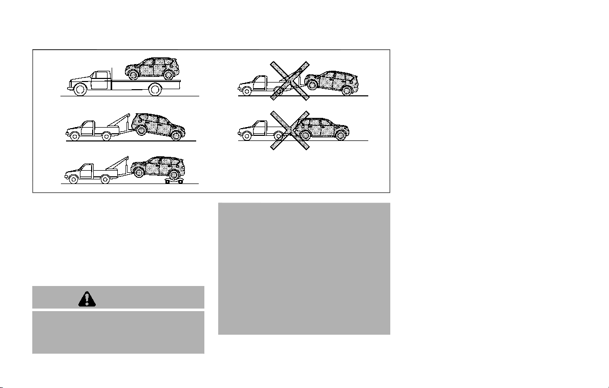
SCE0925
Two-Wheel Drive (2WD) models
TOWING RECOMMENDED BY
NISSAN
Two-Wheel Drive (2WD) models
NISSAN recommends that your vehicle be
towed with the driving (rear) wheels off
the ground or place the vehicle on a flat
bed truck as illustrated.
CAUTION
. Never tow automatic transmis-
sion models with the rear wheels
on the ground or four wheels on
the ground (forward or back-
ward), as this may cause serious
and expensive damage to the
transmission. If it is necessary to
tow the vehicle with the front
wheels raised, always use towing
dollies under the rear wheels.
. When towing rear wheel drive
models with the front wheels on
the ground or on towing dollies:
Place the ignition in the ACC or ON
position, and secure the steering
wheel in a straight-ahead posi-
tion with a rope or similar device.
In case of emergency 6-17
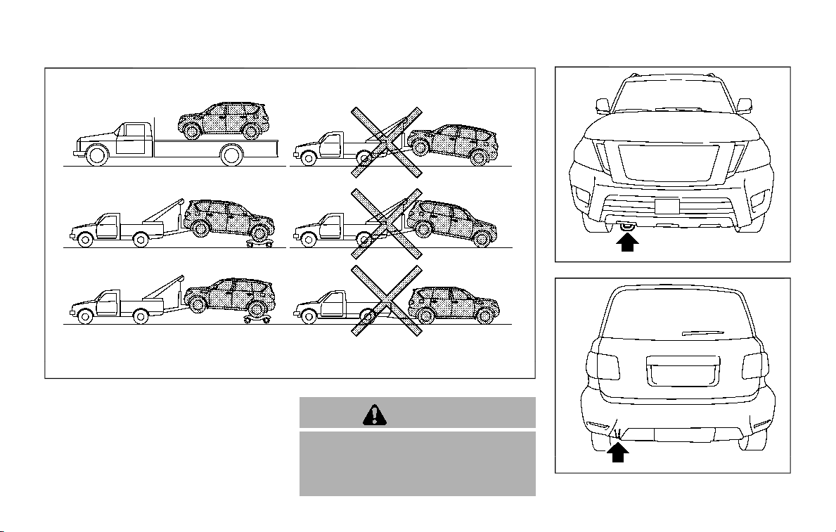
6-18 In case of emergency
SCE0907
Four-Wheel Drive (4WD) models
Four-Wheel Drive (4WD) models
NISSAN recommends that towing dollies
be used when towing your vehicle or the
vehicle be placed on a flat bed truck as
illustrated.
CAUTION
Never tow 4WD models with any of
the wheels on the ground as this
may cause serious and expensive
damage to the powertrain.
JVE0350X
Front
JVE0351X
Rear

VEHICLE RECOVERY (freeing a stuck
vehicle)
WARNING
. Stand clear of a stuck vehicle.
. Do not spin your tires at high
speed. This could cause them to
explode and result in serious in-
jury. Parts of your vehicle could
also overheat and be damaged.
Pulling a stuck vehicle
If your vehicle is stuck in sand, snow, mud,
etc., use a tow strap or other device
designed specifically for vehicle recovery.
Always follow the manufacturer’s instruc-
tions for the recovery device.
Attach the tow strap to the towing hook.
CAUTION
. Tow chains or cables must be
attached only to the main struc-
tural members of the vehicle or
the towing hooks. Otherwise, the
vehicle body will be damaged.
. Use the towing hook only to free
a vehicle stuck in sand, snow,
mud, etc. Never tow the vehicle
for a long distance using only the
towing hook.
. The towing hook is under tre-
mendous force when used to free
a stuck vehicle. Never pull the
hook at an angle.
. Always pull the cable straight out
from the front or rear of the
vehicle.
. Pulling devices should be routed
so they do not touch any part of
the suspension, steering, brake or
cooling systems.
. Pulling devices such as ropes or
canvas straps are not recom-
mended for use in vehicle towing
or recovery.
Rocking a stuck vehicle
If your vehicle is stuck in sand, snow, mud,
etc., use the following procedure:
1. Turn off the Vehicle Dynamic Control
(VDC) system.
2. Make sure the area in front and
behind the vehicle is clear of obstruc-
tions.
3. Turn the steering wheel right and left
to clear an area around the front tires.
4. Slowly rock the vehicle forward and
backward.
.
Shift back and forth between R
(Reverse) and D (Drive).
.
Apply the accelerator as little as
possible to maintain the rocking
motion.
.
Release the accelerator pedal be-
fore shifting between R and D.
.
Do not spin the tires above 35 MPH
(55 km/h).
5. If the vehicle cannot be freed after a
few tries, contact a professional tow-
ing service to remove the vehicle.
In case of emergency 6-19

6-20 In case of emergency
This section describes the procedure for
manually shifting the vehicle into the 4WD
mode (4L position) in case of an emer-
gency.
WHEN 4WD WARNING LIGHT ILLU-
MINATES
If the 4WD warning light illuminates while
driving, there may be a malfunction in the
4WD system. Stop the vehicle and have
the vehicle checked as soon as possible. It
is recommended you contact a NISSAN
dealer for this service. (See “NISSAN all-
mode 4WD®” (P.5-116).)
When the vehicle is stuck on an uneven
road (desert, mud, etc.) and the 4WD
warning light is illuminated, be sure to
place the 4WD shift switch in the 4L
position. If only the rear wheels are
spinning, this means that the transfer
has not switched to the 4L position
electrically.
If this situation occurs, contact a dealer or
road assistance service for help. If an
immediate service is not available, per-
form the following procedure to switch to
the 4L position manually and free the
vehicle.
CAUTION
Only perform this procedure in an
emergency.
If the vehicle is driven for a long
period of time over a long distance
with a component detached, foreign
material such as water, sand, etc.
may enter from the opening and this
may cause a malfunction in the
drivetrain system. After freeing a
vehicle that has become stuck, it is
recommended you contact a NISSAN
dealer for inspection and repair.
WARNING
. Ensure your safety before per-
forming the operations. The ve-
hicle may move unexpectedly.
. Place the ignition switch in the
OFF position, apply the parking
brake and let the vehicle cool
down.
. Do not perform the following
procedure immediately after
driving the vehicle. Parts such as
exhaust components, the trans-
mission, etc. are very hot and
may cause a burn injury.
. Make sure that the parts that will
be operated as well as related
parts cool down before perform-
ing the operation.
. Burrs or projecting portions of
metal components may cause
unexpected injury to your fingers
or arms. Pay special attention in
regard to your safety while re-
moving and installing these
parts. Wear work gloves and pro-
tective arm covers.
CAUTION
While removing and installing the
parts, prevent the removed parts
from getting dirty with water, dirt or
sand. Protect the parts using a cover
such as a clean cloth, etc.
FOUR-WHEEL DRIVE (4WD)
MANUAL SHIFTING (4WD models)
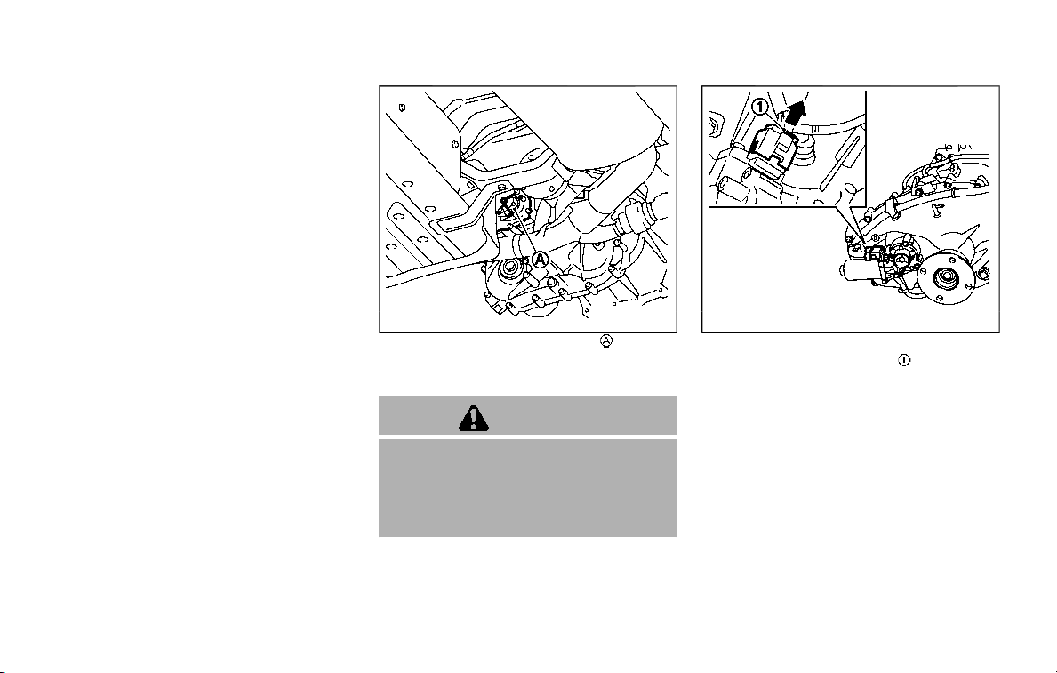
OPERATING PROCEDURE
Place the ignition switch in the OFF
position and apply the parking brake. Let
the vehicle cool down before performing
the following procedure.
SCE0959
4WD shift motor assembly
1. Check that the ignition switch is in the
OFF position.
CAUTION
The following procedure includes the
removal of the electrical system
components. Therefore, make sure
that the ignition switch is in the OFF
position before proceeding.
SCE0960
4WD shift motor harness connector
2. Unlock the upper lock of the har-
ness connector of the 4WD shift motor
assembly, then remove the harness
connector.
3. Cover the connector to prevent it
from getting dirty, and then fasten
the connector to the vehicle using a
suitable rope so that the connector
does not contact the exhaust muffler,
etc.
In case of emergency 6-21
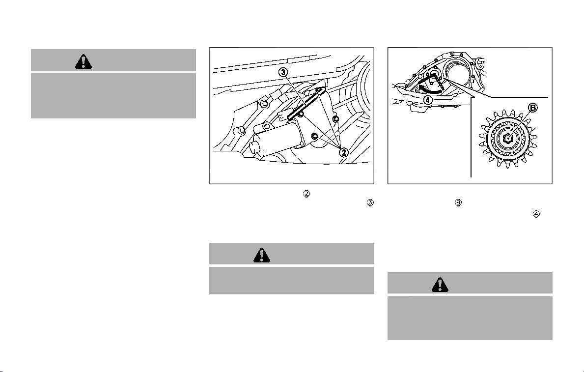
6-22 In case of emergency
CAUTION
The connector must be fastened
securely. Not doing so may result in
damage to the connector due to
interference with other parts.
SCE0961
4. Remove the 4 bolts that secure the
4WD shift motor using the wrench
that is equipped in the vehicle.
5. Remove the 4WD shift motor assem-
bly.
CAUTION
Be careful not to allow the assembly
to contact water, dirt or sand.
SCE0962
6. Completely insert the wrench into the
internal gear
of the transfer.
7. Fully turn the wrench clockwise
as
far as it will go. This shifts the transfer
to the 4L position.
8. Install the 4WD shift motor assembly.
Securely tighten the 4 bolts using the
wrench.
CAUTION
. Do not connect the harness con-
nector of the 4WD shift motor
after the above procedure has
been performed.

. The 4 bolts are tightened to
temporarily install the 4WD shift
motor so that water, dirt or sand
does not enter inside the system.
Therefore, they should only be
tightened to the proper tighten-
ing torque. It is recommended
you contact a NISSAN dealer for
inspection and repair.
9. With the 4WD system in the 4L posi-
tion, free the stuck vehicle. (See “Ve-
hicle recovery (freeing a stuck vehicle)”
(P.6-19) for details.)
CAUTION
After manually shifting the vehicle to
the 4L position, it is recommended
you contact a NISSAN dealer for
inspection and repair as soon as
possible.
In case of emergency 6-23

6-24 In case of emergency
MEMO

7 Appearance and care
Cleaning exterior ........................................................................... 7-2
Washing ......................................................................................... 7-2
Waxing ............................................................................................ 7-2
Removing spots ...................................................................... 7-3
Underbody ................................................................................... 7-3
Glass ................................................................................................. 7-3
Wheels ............................................................................................. 7-3
Chrome parts ............................................................................ 7-4
Tire dressing .............................................................................. 7-4
Cleaning interior ........................................................................... 7-5
Air fresheners ......................................................................... 7-5
Floor mats ................................................................................. 7-5
Seat belts ................................................................................... 7-7
Corrosion protection ................................................................ 7-7
Most common factors contributing to
vehicle corrosion .................................................................. 7-7
Environmental factors influence the rate
of corrosion .............................................................................. 7-7
To protect your vehicle from corrosion ............ 7-8

7-2 Appearance and care
In order to maintain the appearance of
your vehicle, it is important to take proper
care of it.
To protect the paint surface, wash your
vehicle as soon as you can:
. after a rainfall to prevent possible
damage from acid rain
. after driving on coastal roads
. when contaminants such as soot, bird
droppings, tree sap, metal particles or
bugs get on the paint surface
. when dust or mud builds up on the
surface
Whenever possible, store or park your
vehicle inside a garage or in a covered
area.
When it is necessary to park outside, park
in a shady area or protect the vehicle with
a body cover.
Be careful not to scratch the paint
surface when putting on or removing
the body cover.
WASHING
Wash dirt off the vehicle with a wet
sponge and plenty of water. Clean the
vehicle thoroughly using a mild soap, a
special vehicle soap or general purpose
dishwashing liquid mixed with clean, lu-
kewarm (never hot) water.
CAUTION
. Do not use car washes that use
acid in the detergent. Some car
washes, especially brushless
ones, use some acid for cleaning.
The acid may react with some
plastic vehicle components, caus-
ing them to crack. This could
affect their appearance, and also
could cause them not to function
properly. Always check with your
car wash to confirm that acid is
not used.
. Do not wash the vehicle with
strong household soap, strong
chemical detergents, gasoline or
solvents.
. Do not wash the vehicle in direct
sunlight or while the vehicle body
is hot, as the surface may become
water-spotted.
. Avoid using tight-napped or
rough cloths, such as washing
mitts. Care must be taken when
removing caked-on dirt or other
foreign substances so the paint
surface is not scratched or da-
maged.
. Lock all doors before going
through automatic car wash.
Locking doors helps prevent
fuel-filler door from opening and
becoming damaged.
Rinse the vehicle again with plenty of
clean water.
Inside flanges, seams and folds on the
doors, hatches and hood are particularly
vulnerable to the effects of road salt.
Therefore, these areas must be regularly
cleaned. Make sure that the drain holes in
the lower edge of the door are open.
Spray water under the body and in the
wheel wells to loosen the dirt and wash
away road salt.
Avoid leaving water spots on the paint
surface by using a damp chamois to dry
the vehicle.
WAXING
Regular waxing protects the paint surface
and helps retain new vehicle appearance.
Polishing is recommended to remove
built-up wax residue and to avoid a
weathered appearance before reapplying
wax.
A NISSAN dealer can assist you in choos-
ing the proper product.
CLEANING EXTERIOR

. Wax your vehicle only after a thorough
washing. Follow the instructions sup-
plied with the wax.
. Do not use a wax containing any
abrasives, cutting compounds or clea-
ners that may damage the vehicle
finish.
Machine compound or aggressive polish-
ing on a base coat/clear coat paint finish
may dull the finish or leave swirl marks.
REMOVING SPOTS
Remove tar and oil spots, industrial dust,
insects, and tree sap as quickly as possi-
ble from the paint surface to avoid lasting
damage or staining. Special cleaning
products are available at a NISSAN dealer
or any automotive accessory stores.
UNDERBODY
In areas where road salt is used in winter,
the underbody must be cleaned regularly.
This will prevent dirt and salt from build-
ing up and causing the acceleration of
corrosion on the underbody and suspen-
sion. Before the winter period and again
in the spring, the underseal must be
checked and, if necessary, re-treated.
GLASS
Use glass cleaner to remove smoke and
dust film from the glass surfaces. It is
normal for glass to become coated with a
film after the vehicle is parked in the hot
sun. Glass cleaner and a soft cloth will
easily remove this film.
CAUTION
When cleaning the inside of the
windows, do not use sharp-edged
tools, abrasive cleaners or chlorine-
based disinfectant cleaners. They
could damage the electrical conduc-
tors, radio antenna elements or rear
window defroster elements.
WHEELS
Wash the wheels when washing the
vehicle to maintain their appearance.
. Clean the inner side of the wheels
when the wheel is changed or the
underside of the vehicle is washed.
. Inspect wheel rims regularly for dents
or corrosion. Such damage may cause
loss of pressure or poor seal at the tire
bead.
. NISSAN recommends that the road
wheels be waxed to protect against
road salt in areas where it is used
during winter.
CAUTION
Do not use abrasive cleaners when
washing the wheels.
Aluminum alloy wheels
Wash regularly with a sponge dampened
in a mild soap solution, especially during
winter months in areas where road salt is
used. Salt could discolor the wheels if not
removed.
CAUTION
Follow the directions below to avoid
staining or discoloring the wheels:
. Do not use a cleaner that uses
strong acid or alkali contents to
clean the wheels.
. Do not apply wheel cleaners to
the wheels when they are hot.
The wheel temperature should be
the same as ambient tempera-
ture.
Appearance and care 7-3

7-4 Appearance and care
. Rinse the wheel to completely
remove the cleaner within 15
minutes after the cleaner is ap-
plied.
Bright wheels (if so equipped)
The bright wheels use a different coating
process than typical aluminum alloy
wheel and they are not plated wheels.
These wheels are clear-coated and re-
quire the following special cleaning. They
should be regularly washed with a soft
sponge soaked in a lot of water. After
washing with water, wipe clean with a
dry, soft cloth and dry completely. When
there is chemical or tire wax, or dirt such
as an antifreeze agent on the surface,
wash them with water as soon as possi-
ble.
CAUTION
. The surfaces of the wheels use a
different coating process than
typical aluminum alloy wheels.
Do not use aluminum alloy wheel
cleaners or abrasive cleaners to
clean the wheels. Using such
cleaners could damage the wheel
surfaces.
. Do not use an automatic car wash
if the vehicle is equipped with
bright wheels. The wheel coating
may be damaged.
. Do not use a brush to wash the
wheels if the vehicle is equipped
with bright wheels. The wheel
coating may be damaged.
CHROME PARTS
Clean chrome parts regularly with a non-
abrasive chrome polish to maintain the
finish.
TIRE DRESSING
NISSAN does not recommend the use of
tire dressings. Tire manufacturers apply a
coating to the tires to help reduce dis-
coloration of the rubber. If a tire dressing
is applied to the tires, it may react with
the coating and form a compound. This
compound may come off the tire while
driving and stain the vehicle paint.
If you choose to use a tire dressing, take
the following precautions:
. Use a water-based tire dressing. The
coating on the tire dissolves more
easily with an oil-based tire dressing.
. Apply a light coat of tire dressing to
help prevent it from entering the tire
tread/grooves (where it would be
difficult to remove).
. Wipe off excess tire dressing using a
dry towel. Make sure the tire dressing
is completely removed from the tire
tread/grooves.
. Allow the tire dressing to dry as
recommended by tire dressing manu-
facturer.

Occasionally remove loose dust from the
interior trim, plastic parts and seats using
a vacuum cleaner or soft bristled brush.
Wipe the vinyl and leather surfaces with a
clean, soft cloth dampened in mild soap
solution, then wipe clean with a dry soft
cloth.
Regular care and cleaning is required in
order to maintain the appearance of the
leather.
Before using any fabric protector, read
the manufacturer’s recommendations.
Some fabric protectors contain chemicals
that may stain or bleach the seat materi-
al.
Use a cloth dampened only with water, to
clean the meter and gauge lens.
WARNING
Do not use water or acidic cleaners
(hot steam cleaners) on the seat. This
can damage the seat or occupant
classification sensors. This can also
affect the operation of the air bag
system and result in serious perso-
nal injury.
CAUTION
. Never use benzine, thinner, or any
similar material.
. For cleaning, use a soft cloth,
dampened with water. Never use
a rough cloth, alcohol, benzine,
thinner or any kind of solvent or
paper towel with a chemical
cleaning agent. They will scratch
or cause discoloration to the lens.
. Do not spray any liquid such as
water on the meter lens. Spraying
liquid may cause the system to
malfunction.
. Small dirt particles can be abra-
sive and damaging to the leather
surfaces and should be removed
promptly. Do not use saddle soap,
car waxes, polishes, oils, cleaning
fluids, solvents, detergents or
ammonia-based cleaners as they
may damage the leather’s natural
finish.
. Only use fabric protectors ap-
proved by NISSAN.
. Do not use glass or plastic cleaner
on meter or gauge lens covers. It
may damage the lens cover.
AIR FRESHENERS
Most air fresheners use a solvent that
could affect the vehicle interior. If you use
an air freshener, take the following pre-
cautions:
. Hanging-type air fresheners can
cause permanent discoloration when
they contact vehicle interior surfaces.
Place the air freshener in a location
that allows it to hang free and not
contact an interior surface.
. Liquid-type air fresheners typically clip
on the vents. These products can
cause immediate damage and disco-
loration when spilled on interior sur-
faces.
Carefully read and follow the manufac-
turer’s instructions before using air fresh-
eners.
FLOOR MATS
WARNING
To avoid potential pedal interference
that may result in a collision, injury
or death:
. NEVER place a floor mat on top of
another floor mat in the driver
front position or install them up-
side down or backwards.
Appearance and care 7-5
CLEANING INTERIOR
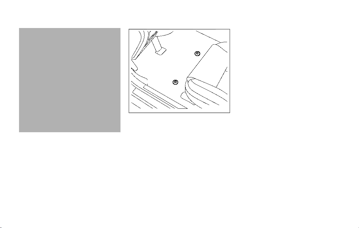
7-6 Appearance and care
. Use only genuine NISSAN floor
mats or equivalent floor mats
that are specifically designed for
use in your vehicle model and
model year.
. Properly position the mats in the
floorwell using the floor mat po-
sitioning hooks. See “Floor mat
installation” (P.7-6).
. Make sure the floor mat does not
interfere with pedal operation.
. Periodically check the floor mats
to make sure they are properly
installed.
. After cleaning the vehicle interior,
check the floor mats to make
sure they are properly installed.
The use of genuine NISSAN floor mats can
extend the life of your vehicle carpet and
make it easier to clean the interior. Mats
should be maintained with regular clean-
ing and replaced if they become exces-
sively worn.
JVA0034X
Front (example)
Floor mat installation
Your vehicle is equipped with floor mat
positioning hook(s). The number and
shape of the floor mat positioning hooks
for each seating position varies depend-
ing on the vehicle.
When installing genuine NISSAN floor
mats, follow the installation instructions
provided with the floor mat and the
following:
1. Position the floor mat in the floorwell
so that the mat grommet holes are
aligned with the hook(s).
2. Secure the grommet holes into the
hook(s) and ensure that the floor mat
is properly positioned.
3. Make sure the floor mat does not
interfere with pedal operation. With
the ignition in the OFF position and
the shift lever in the P (Park) position,
fully apply and release all pedals. The
floor mat must not interfere with
pedal operation or prevent the pedal
from returning to its normal position.
It is recommended you see a NISSAN
dealer for details about installing the
floor mats in your vehicle.

SAI0052
Bracket positions
The illustration shows the location of the
floor mat positioning hooks.
SEAT BELTS
The seat belts can be cleaned by wiping
them with a sponge dampened in a mild
soap solution. Allow the belts to dry
completely before using them.
See “Seat belts” (P.1-20).
WARNING
Do not allow wet seat belts to roll up
in the retractor. NEVER use bleach,
dye, or chemical solvents to clean
the seat belts, since these materials
may severely weaken the seat belt
webbing.
MOST COMMON FACTORS CON-
TRIBUTING TO VEHICLE CORRO-
SION
. The accumulation of moisture-retain-
ing dirt and debris in body panel
sections, cavities, and other areas.
. Damage to paint and other protective
coatings caused by gravel and stone
chips or minor traffic accidents.
ENVIRONMENTAL FACTORS INFLU-
ENCE THE RATE OF CORROSION
Moisture
Accumulation of sand, dirt and water on
the vehicle body underside can acceler-
ate corrosion. Wet floor coverings will not
dry completely inside the vehicle, and
should be removed for drying to avoid
floor panel corrosion.
Relative humidity
Corrosion will be accelerated in areas of
high relative humidity, especially those
areas where the temperatures stay above
freezing where atmospheric pollution ex-
ists, or where road salt is used.
Appearance and care 7-7
CORROSION PROTECTION

7-8 Appearance and care
Temperature
A temperature increase will accelerate
the rate of corrosion to those parts which
are not well ventilated.
Air pollution
Industrial pollution, the presence of salt in
the air in coastal areas, or heavy road salt
use will accelerate the corrosion process.
Road salt will also accelerate the disin-
tegration of paint surfaces.
TO PROTECT YOUR VEHICLE FROM
CORROSION
. Wash and wax your vehicle often to
keep the vehicle clean.
. Always check for minor damage to the
paint and repair it as soon as possible.
. Keep drain holes at the bottom of the
doors open to avoid water accumula-
tion.
. Check the underbody for accumula-
tion of sand, dirt or salt. If present,
wash with water as soon as possible.
CAUTION
. NEVER remove dirt, sand or other
debris from the passenger com-
partment by washing it out with a
hose. Remove dirt with a vacuum
cleaner.
. Never allow water or other liquids
to come in contact with electronic
components inside the vehicle as
this may damage them.
Chemicals used for road surface deicing
are extremely corrosive. They accelerate
corrosion and deterioration of underbody
components such as the exhaust system,
fuel and brake lines, brake cables, floor
pan and fenders.
In winter, the underbody must be
cleaned periodically.
For additional protection against rust and
corrosion, which may be required in some
areas, it is recommended you consult a
NISSAN dealer.

8 Do-it-yourself
Maintenance precautions ...................................................... 8-2
Engine compartment check locations ........................ 8-3
VK56VD engine ....................................................................... 8-3
Engine cooling system ............................................................. 8-4
Checking engine coolant level .................................... 8-5
Changing engine coolant ................................................ 8-5
Engine oil ............................................................................................. 8-6
Checking engine oil level ................................................. 8-6
Changing engine oil and filter ..................................... 8-6
Automatic Transmission Fluid (ATF) ............................. 8-8
Power steering fluid ................................................................... 8-8
Brake fluid .......................................................................................... 8-9
Window washer fluid .............................................................. 8-10
Battery ................................................................................................ 8-11
Jump starting ......................................................................... 8-13
Variable voltage control system ................................... 8-13
Drive belts ........................................................................................ 8-13
Spark plugs ..................................................................................... 8-14
Replacing spark plugs ..................................................... 8-14
Air cleaner ....................................................................................... 8-15
Windshield wiper blades ..................................................... 8-16
Cleaning ................................................................................... 8-16
Replacing ................................................................................ 8-16
Rear window wiper blades ............................................... 8-17
Brakes ................................................................................................ 8-17
Self-adjusting brakes ..................................................... 8-17
Brake pad wear warning............................................ 8-17
Brake booster ...................................................................... 8-17
Fuses ................................................................................................... 8-18
Engine compartment .................................................... 8-18
Passenger compartment ........................................... 8-20
Intelligent Key battery replacement .......................... 8-21
Lights .................................................................................................. 8-24
Headlights .............................................................................. 8-24
Exterior and interior lights ........................................ 8-26
Wheels and tires ........................................................................ 8-30
Tire pressure ........................................................................ 8-30
Tire labeling .......................................................................... 8-34
Types of tires ....................................................................... 8-36
Tire chains .............................................................................. 8-37
Changing wheels and tires ...................................... 8-37

8-2 Do-it-yourself
When performing any inspection or main-
tenance work on your vehicle, always
take care to prevent serious accidental
injury to yourself or damage to the
vehicle. The following are general precau-
tions which should be closely observed.
WARNING
. Park the vehicle on a level sur-
face, apply the parking brake
securely and block the wheels to
prevent the vehicle from moving.
Move the shift lever to P (Park).
. Be sure the ignition switch is in
the OFF or LOCK position when
performing any parts replace-
ment or repairs.
. Never connect or disconnect the
battery or any transistorized
component while the ignition
switch is in the ON position.
. Never leave the engine or auto-
matic transmission related com-
ponent harnesses disconnected
while the ignition switch is in the
ON position.
. If you must work with the engine
running, keep your hands, cloth-
ing, hair and tools away from
moving fans, belts and any other
moving parts.
. It is advisable to secure or re-
move any loose clothing and
remove any jewelry, such as
rings, watches, etc. before work-
ing on your vehicle.
. Always wear eye protection
whenever you work on your ve-
hicle.
. If you must run the engine in an
enclosed space such as a garage,
be sure there is proper ventilation
for exhaust gases to escape.
. Never get under the vehicle while
it is supported only by a jack. If it
is necessary to work under the
vehicle, support it with safety
stands.
. Keep smoking materials, flame
and sparks away from fuel tank
and the battery.
. Your vehicle is equipped with an
automatic engine cooling fan. It
may come on at any time without
warning, even if the ignition key is
in the OFF position and the en-
gine is not running. To avoid
injury, always disconnect the ne-
gative battery cable before work-
ing near the fan.
. Because the fuel lines are under
high pressure even when the
engine is off, it is recommended
you visit a NISSAN dealer for
service of the fuel filter or fuel
lines.
CAUTION
. Do not work under the hood while
the engine is hot. Turn the engine
off and wait until it cools down.
. Avoid direct contact with used
engine oil and coolant. Impro-
perly disposed engine oil, coolant,
and/or other vehicle fluids can
damage the environment. Always
conform to local regulations for
disposal of vehicle fluid.
This “8. Do-it-yourself” section gives in-
structions regarding only those items
which are relatively easy for an owner to
perform.
A genuine NISSAN Service Manual is also
available. (See “Owner’s Manual/Service
Manual order information” (P.10-34).)
You should be aware that incomplete or
improper servicing may result in operat-
ing difficulties or excessive emissions, and
MAINTENANCE PRECAUTIONS
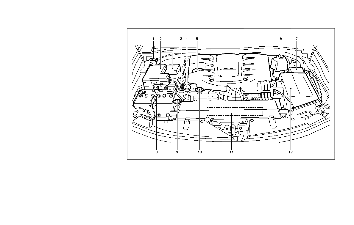
could affect your warranty coverage. If in
doubt about any servicing, it is recom-
mended you have it done by a NISSAN
dealer.
JVC0965X
VK56VD ENGINE
1. Window washer fluid reservoir
2. Fuse/fusible link holder
3. Engine oil dipstick
4. Power steering fluid reservoir
5. Engine oil filler cap
6. Brake fluid reservoir
7. Fuse/fusible link holder
8. Battery
9. Radiator filler cap
10. Engine coolant reservoir
11. Drive belts
12. Air cleaner
Do-it-yourself 8-3
ENGINE COMPARTMENT CHECK LOCATIONS

8-4 Do-it-yourself
The engine cooling system is filled at the
factory with a pre-diluted mixture of 50%
Genuine NISSAN Long Life Antifreeze/
Coolant (blue) and 50% water to provide
year-round anti-freeze and coolant pro-
tection. The antifreeze solution contains
rust and corrosion inhibitors. Additional
engine cooling system additives are not
necessary.
WARNING
. Never remove the radiator or
coolant reservoir cap when the
engine is hot. Wait until the en-
gine and radiator cool down.
Serious burns could be caused
by high pressure fluid escaping
from the radiator. See precau-
tions in “If your vehicle overheats”
(P.6-14).
. The radiator is equipped with a
pressure type radiator cap. To
prevent engine damage, use only
a genuine NISSAN radiator cap.
CAUTION
. Never use any cooling system
additives such as radiator sealer.
Additives may clog the cooling
system and cause damage to
the engine, transmission and/or
cooling system.
. When adding or replacing cool-
ant, be sure to use only Genuine
NISSAN Long Life Antifreeze/
Coolant (blue) or equivalent. Gen-
uine NISSAN Long Life Antifreeze/
Coolant (blue) is pre-diluted to
provide antifreeze protection to
−34°F (−37°C). If additional freeze
protection is needed due to
weather where you operate your
vehicle, add Genuine NISSAN Long
Life Antifreeze/Coolant (blue)
concentrate following the direc-
tions on the container. If an
equivalent coolant other than
Genuine NISSAN Long Life Anti-
freeze/Coolant (blue) is used, fol-
low the coolant manufacturer’s
instructions to maintain mini-
mum antifreeze protection to
−34°F (−37°C). The use of other
types of coolant solutions other
than Genuine NISSAN Long Life
Antifreeze/Coolant (blue) or
equivalent may damage the en-
gine cooling system.
. The life expectancy of the fac-
tory-fill coolant is 105,000 miles
(168,000 km) or 7 years. Mixing
any other type of coolant other
than Genuine NISSAN Long Life
Antifreeze/Coolant (blue), includ-
ing Genuine NISSAN Long Life
Antifreeze/Coolant (green), or
the use of non-distilled water will
reduce the life expectancy of the
factory-fill coolant. Refer to the
“9. Maintenance and schedules”
section of this manual for more
details.
ENGINE COOLING SYSTEM
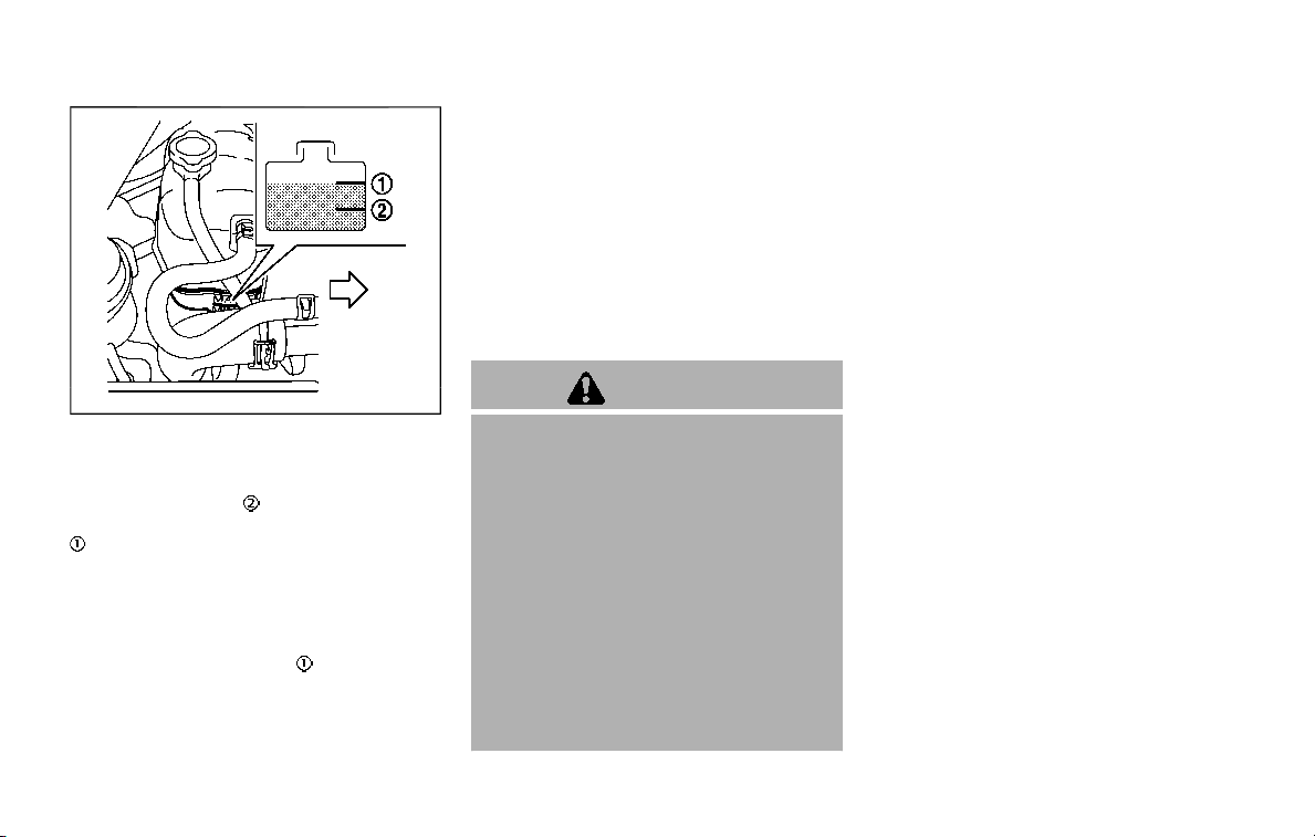
JVM0733X
CHECKING ENGINE COOLANT LEVEL
Check the coolant level in the reservoir
when the engine is cold. If the coolant
level is below MIN
, open the reservoir
tank cap and add coolant up to the MAX
level. If the reservoir tank is empty,
check the coolant level in the radiator
when the engine is cold. If there is
insufficient coolant in the radiator, fill the
radiator with coolant up to the filler
opening and also add it to the reservoir
tank up to the MAX level
.
Tighten the cap securely after adding
engine coolant.
If the cooling system requires coolant
frequently, have it checked. It is recom-
mended you visit a NISSAN dealer for
this service.
CHANGING ENGINE COOLANT
It is recommended that major cooling
system repairs be performed by a NISSAN
dealer. The service procedures can be
found in the appropriate NISSAN Service
Manual.
Improper servicing can result in re-
duced heater performance and engine
overheating.
WARNING
. To avoid the danger of being
scalded, never change the cool-
ant when the engine is hot.
. Never remove the radiator cap or
coolant reservoir cap when the
engine is hot. Serious burns could
be caused by high pressure fluid
escaping from the radiator.
. Avoid direct skin contact with
used coolant. If skin contact is
made, wash thoroughly with soap
or hand cleaner as soon as pos-
sible.
. Keep coolant out of reach of
children and pets.
Engine coolant must be disposed of
properly. Check your local regulations.
Do-it-yourself 8-5
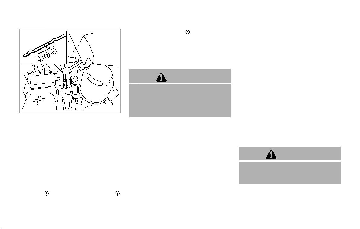
8-6 Do-it-yourself
JVM0728X
CHECKING ENGINE OIL LEVEL
1. Park the vehicle on a level surface and
apply the parking brake.
2. Run the engine until it reaches oper-
ating temperature.
3. Turn off the engine. Wait more than
15 minutes for the oil to drain back
into the oil pan.
4. Remove the dipstick and wipe it clean.
Reinsert it all the way.
5. Remove the dipstick again and check
the oil level. It should be within the
range
. If the oil level is below ,
remove the oil filler cap and pour
recommended oil through the open-
ing. Do not overfill
.
6. Recheck oil level with the dipstick.
It is normal to add some oil between oil
maintenance intervals or during the
break-in period, depending on the se-
verity of operating conditions.
CAUTION
Oil level should be checked regularly.
Operating the engine with an insuffi-
cient amount of oil can damage the
engine, and such damage is not
covered by warranty.
CHANGING ENGINE OIL AND FILTER
Vehicle set-up
1. Park the vehicle on a level surface and
apply the parking brake.
2. Run the engine until it reaches oper-
ating temperature.
3. Turn the engine off and wait more
than 15 minutes.
4. Raise and support the vehicle using a
suitable floor jack and safety jack
stands.
.
Place the safety jack stands under
the vehicle jack-up points.
.
A suitable adapter should be at-
tached to the jack stand saddle.
5. Remove the engine undercover.
.
Remove the bolts that hold the
undercover in place.
CAUTION
Make sure the correct lifting and
support points are used to avoid
vehicle damage.
ENGINE OIL
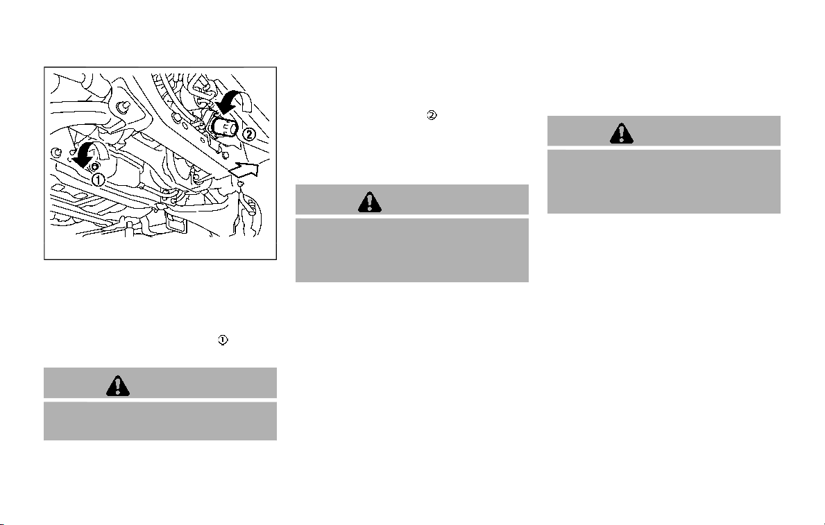
SDI2528
Engine oil and filter
1. Place a large drain pan under the
drain plug.
2. Remove the oil filler cap.
3. Remove the drain plug
with a
wrench and completely drain the oil.
CAUTION
Be careful not to burn yourself, as
the engine oil is hot.
.
Waste oil must be disposed of
properly.
.
Check your local regulations.
4. (Perform steps 4 to 7 only when the
engine oil filter change is needed.)
Loosen the oil filter
with an oil filter
wrench. Remove the oil filter by turn-
ing it by hand.
5. Wipe the engine oil filter mounting
surface with a clean rag.
CAUTION
Be sure to remove any old rubber
gasket remaining on the mounting
surface of the engine. Failure to do
so could lead to engine damage.
6. Coat the gasket on the new filter with
clean engine oil.
7. Screw in the oil filter clockwise until a
slight resistance is felt, then tighten
additionally more than 2/3 turn.
Oil filter tightening torque:
11 to 15 ft-lb
(15 to 21 N·m)
8. Clean and re-install the drain plug
with a new washer. Securely tighten
the drain plug with a wrench.
Drain plug tightening torque:
22 to 29 ft-lb
(29 to 39 N·m)
Do not use excessive force.
9. Refill engine with recommended oil
and install the oil filler cap securely.
CAUTION
The dipstick must be inserted in
place to prevent oil spillage from
the dipstick hole while filling the
engine with oil.
See “Capacities and recommended
fluids/lubricants” (P.10-2) for drain
and refill capacity. The drain and refill
capacity depends on the oil tempera-
ture and drain time. Use these speci-
fications for reference only. Always
use the dipstick to determine the
proper amount of oil in the engine.
10. Start the engine and check for leak-
age around the drain plug and the oil
filter. Correct as required.
11. Turn the engine off and wait more
than 15 minutes. Check the oil level
with the dipstick. Add engine oil if
necessary.
Do-it-yourself 8-7
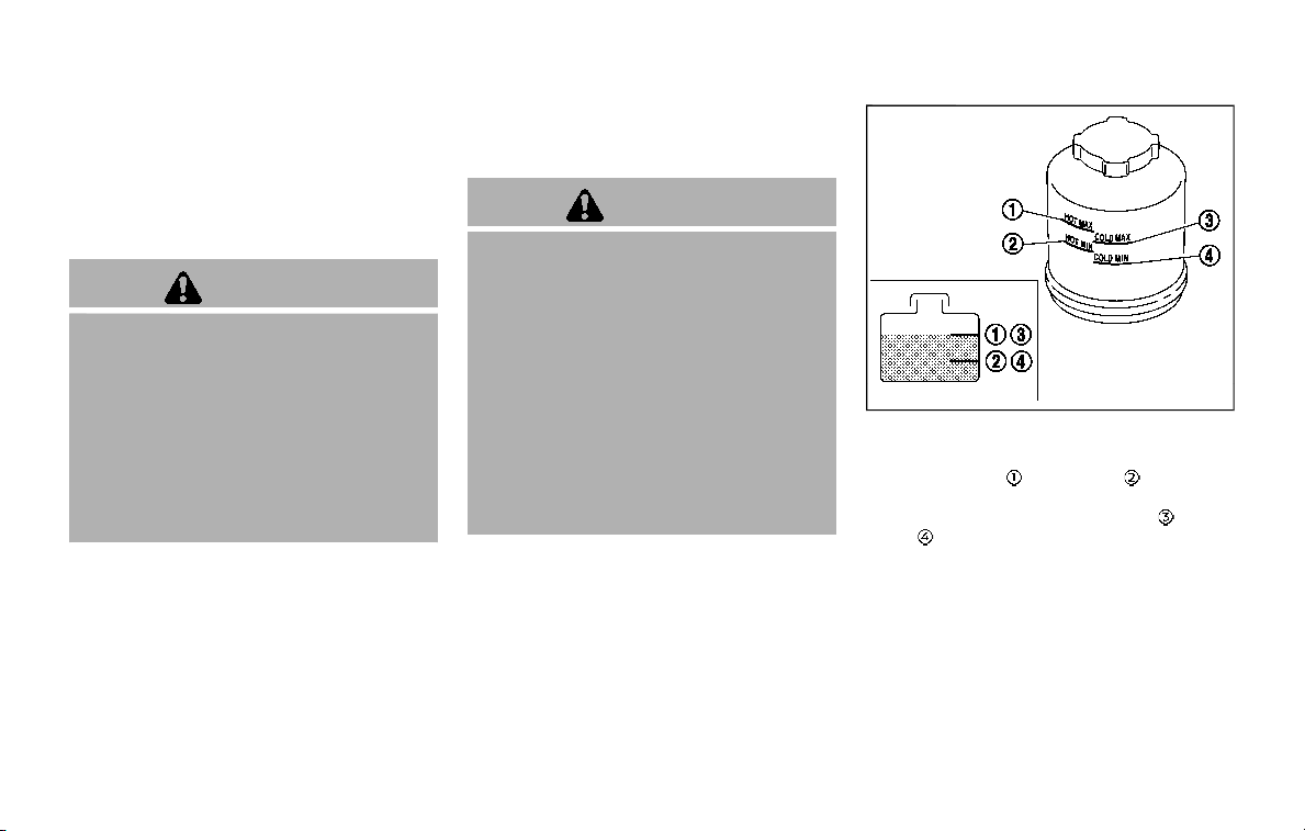
8-8 Do-it-yourself
After the operation
1. Install the engine undercover into
position using the bolts.
2. Lower the vehicle carefully to the
ground.
3. Dispose of waste oil and filter properly.
WARNING
. Prolonged and repeated contact
with used engine oil may cause
skin cancer.
. Try to avoid direct skin contact
with used oil. If skin contact is
made, wash thoroughly with soap
or hand cleaner as soon as pos-
sible.
. Keep used engine oil out of reach
of children.
When checking or replacement is re-
quired, we recommend a NISSAN dealer
for servicing.
CAUTION
. It is recommended that you use
only Genuine NISSAN Matic S ATF.
Do not mix with other fluids.
. Using automatic transmission
fluid (ATF) other than Genuine
NISSAN Matic S ATF may cause
deterioration in driveability and
automatic transmission durabil-
ity, and may damage the auto-
matic transmission. Damage
caused by use of fluids other than
as recommended is not covered
by the NISSAN new vehicle limited
warranty.
SDI1765A
Check the fluid level in the reservoir.
The fluid level should be checked using
the HOT range (
: HOT MAX., : HOT MIN.)
at fluid temperatures of 122 to 176°F (50 to
80°C) or using the COLD range (
: COLD
MAX.,
: COLD MIN.) at fluid temperatures
of 32 to 86°F (0 to 30°C).
If the fluid is below the MIN line, add
Genuine NISSAN PSF or equivalent. Re-
move the cap and fill through the open-
ing.
AUTOMATIC TRANSMISSION FLUID (ATF)
POWER STEERING FLUID

CAUTION
. Do not overfill.
. Use Genuine NISSAN PSF or
equivalent.
For further brake fluid specification infor-
mation, see “Capacities and recom-
mended fluids/lubricants” (P.10-2).
WARNING
. Use only new fluid from a sealed
container. Old, inferior or con-
taminated fluid may damage the
brake system. The use of impro-
per fluids can damage the brake
system and affect the vehicle’s
stopping ability.
. Be sure to clean the filler cap
before removing.
. Brake fluid is poisonous and
should be stored carefully in
marked containers out of the
reach of children.
CAUTION
. Do not add brake fluid with the
ignition switch in the ON position
or the engine running. Doing so
could make the brake fluid over-
fill when the ignition switch is
turned off.
. Do not spill the fluid on painted
surfaces. This will damage the
paint. If fluid is spilled, wash the
surface with water.
Do-it-yourself 8-9
BRAKE FLUID
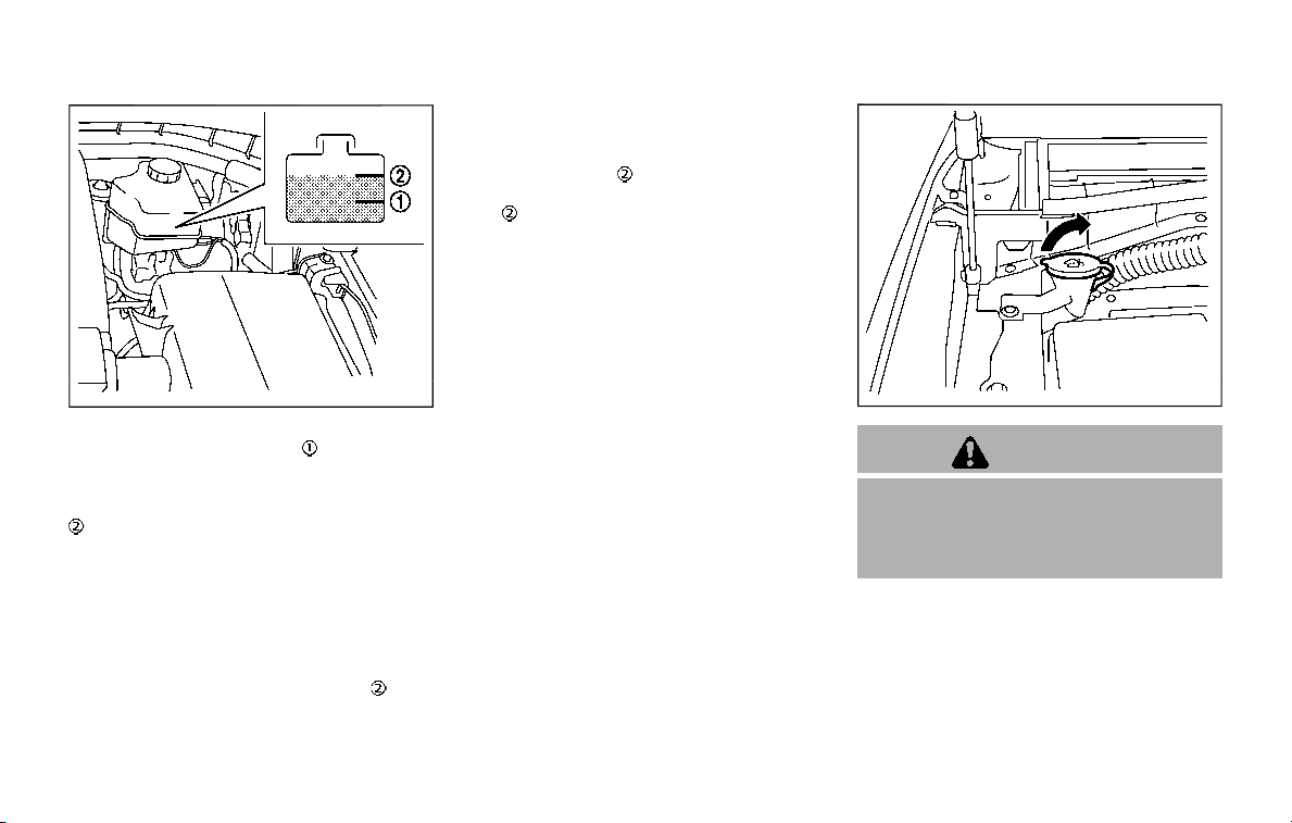
8-10 Do-it-yourself
SDI2513
Check the fluid level in the reservoir. If the
fluid is below the MIN line
or the brake
warning light comes on, add Genuine
NISSAN Super Heavy Duty Brake Fluid or
equivalent DOT 3 fluid up to the MAX line
.
To add brake fluid:
1. Be sure the ignition switch is in the
OFF or LOCK position.
2. Depress and release the foot brake
pedal more than 40 times.
3. Open the reservoir filler cap and add
brake fluid up to the MAX line
. (See
“Capacities and recommended fluids/
lubricants” (P.10-2) for the recom-
mended types of brake fluid.)
NOTE:
When the ignition switch is placed in the
ON position after adding brake fluid up
to the MAX line
in the reservoir, the
brake fluid decreases below the MAX
line
. This is normal.
If fluid must be added frequently, the
system should be checked. It is recom-
mended you visit a NISSAN dealer for this
service.
SDI2517
WARNING
Antifreeze is poisonous and should
be stored carefully in marked con-
tainers out of the reach of children
and pets.
Fill the window washer fluid reservoir
periodically. Add window washer fluid
when the low window washer fluid warn-
ing illuminates.
To fill the window washer fluid reservoir,
lift the cap off the reservoir tank and pour
the window washer fluid into the tank
opening.
WINDOW WASHER FLUID

Add a washer solvent to the washer for
better cleaning. In the winter season, add
a windshield washer antifreeze. Follow
the manufacturer’s instructions for the
mixture ratio.
Refill the reservoir more frequently when
driving conditions require an increased
amount of window washer fluid.
Recommended fluid is Genuine NISSAN
Windshield Washer Concentrate Cleaner
& Antifreeze or equivalent.
CAUTION
. Do not substitute engine anti-
freeze coolant for window
washer solution. This may result
in damage to the paint.
. Do not fill the window washer
reservoir tank with washer fluid
concentrates at full strength.
Some methyl alcohol based
washer fluid concentrates may
permanently stain the grille if
spilled while filling the window
washer reservoir tank.
. Pre-mix washer fluid concen-
trates with water to the manu-
facturer’s recommended levels
before pouring the fluid into the
window washer reservoir tank. Do
not use the window washer re-
servoir tank to mix the washer
fluid concentrate and water.
. Keep the battery surface clean and
dry. Clean the battery with a solution
of baking soda and water.
. Make certain the terminal connec-
tions are clean and securely tightened.
. If the vehicle is not to be used for 30
days or longer, disconnect the nega-
tive (−) battery terminal cable to pre-
vent discharging it.
NOTE:
Care should be taken to avoid situations
that can lead to potential battery dis-
charge and potential no-start condi-
tions such as:
1. Installation or extended use of elec-
tronic accessories that consume
battery power when the engine is
not running (Phone chargers, GPS,
DVD players, etc.)
2. Vehicle is not driven regularly and/
or only driven short distances.
In these cases, the battery may need to
be charged to maintain battery health.
WARNING
. Do not expose the battery to
flames or electrical sparks. Hy-
drogen gas generated by the
battery is explosive. Do not allow
battery fluid to contact your skin,
Do-it-yourself 8-11
BATTERY
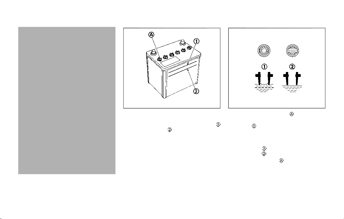
8-12 Do-it-yourself
eyes, fabrics, or painted surfaces.
After touching a battery or bat-
tery cap, do not touch or rub your
eyes. Thoroughly wash your
hands. If the acid contacts your
eyes, skin or clothing, immedi-
ately flush with water for at least
15 minutes and seek medical
attention.
. Do not operate the vehicle if the
fluid in the battery is low. Low
battery fluid can cause a higher
load on the battery which can
generate heat, reduce battery life,
and in some cases lead to an
explosion.
. When working on or near a bat-
tery, always wear suitable eye
protection and remove all jew-
elry.
. Battery posts, terminals and re-
lated accessories contain lead
and lead compounds. Wash
hands after handling.
. Keep the battery out of the reach
of children.
DI0137MA
Check the fluid level in each cell (Remove
the battery cover if it is necessary). It
should be between the UPPER LEVEL
and LOWER LEVEL lines.
If it is necessary to add fluid, add only
distilled water to bring the level to the
indicator in each filler opening. Do not
overfill.
SDI1480C
1. Remove the cell plugs .
2. Add distilled water up to the UPPER
LEVEL
line.
If the side of the battery is not clear,
check the distilled water level by
looking directly above the cell; the
condition
indicates OK and the
conditions
needs more to be added.
3. Tighten cell plugs
.
Vehicles operated in high temperatures
or under severe conditions require fre-
quent checks of the battery fluid level.
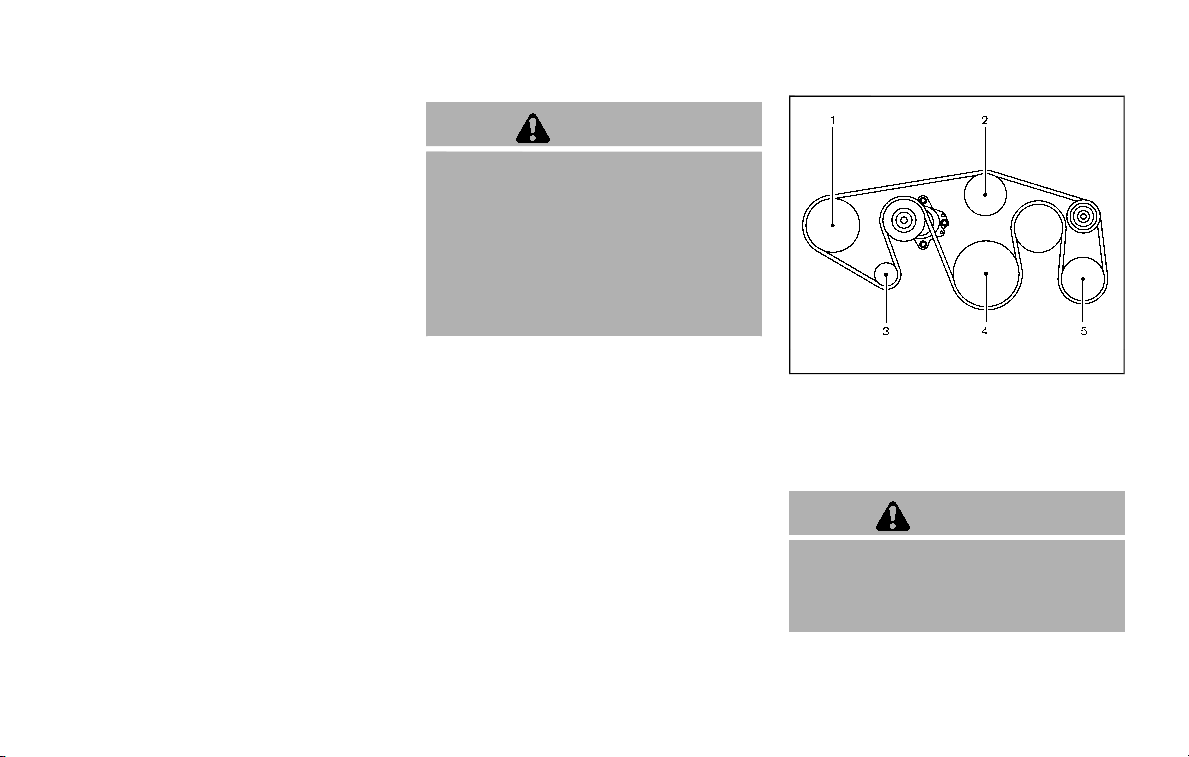
JUMP STARTING
If jump starting is necessary, see “Jump
starting” (P.6-12). If the engine does not
start by jump starting, the battery may
have to be replaced. It is recommended
you visit a NISSAN dealer for this service.
CAUTION
. Do not ground accessories di-
rectly to the battery terminal.
Doing so will bypass the variable
voltage control system and the
vehicle battery may not charge
completely.
. Use electrical accessories with
the engine running to avoid dis-
charging the vehicle battery.
The variable voltage control system mea-
sures the amount of electrical discharge
from the battery and controls voltage
generated by the generator.
SDI2533
1. Power steering fluid pump
2. Water pump
3. Alternator
4. Crankshaft pulley
5. Air conditioner compressor
WARNING
Be sure the ignition switch is in the
OFF or LOCK position before servi-
cing drive belts. The engine could
rotate unexpectedly.
1. Visually inspect each belt for signs of
unusual wear, cuts, fraying or loosen-
ess. If the belt is in poor condition or
Do-it-yourself 8-13
VARIABLE VOLTAGE CONTROL SYSTEM
DRIVE BELTS

8-14 Do-it-yourself
loose, have it replaced or adjusted. It is
recommended you visit a NISSAN
dealer for this service.
2. Have the belts checked regularly for
condition and tension in accordance
with the maintenance schedule
shown in the “9. Maintenance and
schedules” section.
WARNING
Be sure the engine and the ignition
switch are off and that the parking
brake is engaged securely.
CAUTION
Be sure to use the correct socket to
remove the spark plugs. An incorrect
socket can damage the spark plugs.
SDI2020
REPLACING SPARK PLUGS
If replacement is required, it is recom-
mended you visit a NISSAN dealer for this
service.
Iridium-tipped spark plugs
It is not necessary to replace the iridium-
tipped spark plugs as frequently as the
conventional type spark plugs since they
will last much longer. Follow the main-
tenance schedule shown in the “9. Main-
tenance and schedules” section, but do
not reuse them by cleaning or regapping.
Always replace spark plugs with recom-
mended or equivalent ones.
SPARK PLUGS

SDI2515
To remove the filter, release the lock pins
and pull the unit upward .
The filter element should not be cleaned
and reused. Replace it according to the
maintenance schedule shown in the “9.
Maintenance and schedules” section.
When replacing the filter, wipe the inside
of the air cleaner housing and the cover
with a damp cloth.
WARNING
. Operating the engine with the air
cleaner removed can cause you
or others to be burned. The air
cleaner not only cleans the air, it
stops flame if the engine back-
fires. If it isn’t there, and the
engine backfires, you could be
burned. Do not drive with the air
cleaner removed, and be careful
when working on the engine with
the air cleaner removed.
. Never pour fuel into the throttle
body or attempt to start the
engine with the air cleaner re-
moved. Doing so could result in
serious injury.
Do-it-yourself 8-15
AIR CLEANER
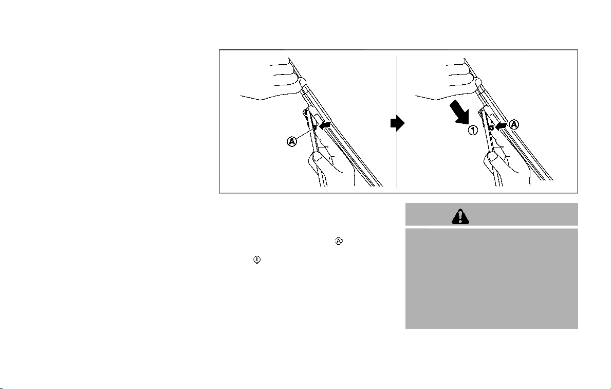
8-16 Do-it-yourself
CLEANING
If your windshield is not clear after using
the windshield washer or if a wiper blade
chatters when running, wax or other
material may be on the blade or wind-
shield.
Clean the outside of the windshield with a
washer solution or a mild detergent. Your
windshield is clean if beads do not form
when rinsing with clear water.
Clean each blade by wiping it with a cloth
soaked in a washer solution or a mild
detergent. Then rinse the blade with clear
water. If your windshield is still not clear
after cleaning the blades and using the
wiper, replace the blades.
Worn windshield wiper blades can da-
mage the windshield and impair driver
vision.
When a washer nozzle is clogged
It is recommended you see a NISSAN
dealer if a washer nozzle is clogged or
any malfunction occurs. Do not attempt
to clean the nozzle using a needle or a
pin. Doing so may damage the nozzle.
SDI2048
REPLACING
Replace the wiper blades if they are worn.
1. Pull the wiper arm.
2. Push the release tab
, and then
move the wiper blade down the wiper
arm
while pushing the release tab
to remove.
3. Insert the new wiper blade onto the
wiper arm until a click sounds.
4. Rotate the wiper blade so the dimple
is in the groove.
CAUTION
. After wiper blade replacement,
return the wiper arm to its origi-
nal position;
otherwise it may be damaged
when the hood is opened.
. Make sure the wiper blades con-
tact the glass; otherwise the arm
may be damaged from wind
pressure.
WINDSHIELD WIPER BLADES

It is recommended you visit a NISSAN
dealer if checking or replacement is
required.
If the brakes do not operate properly,
have the brakes checked. It is recom-
mended that you visit a NISSAN dealer for
this service.
SELF-ADJUSTING BRAKES
Your vehicle is equipped with self-adjust-
ing brakes.
The disc-type brakes self-adjust every
time the brake pedal is applied.
WARNING
Have your brake system checked if
the brake pedal height does not
return to normal. It is recommended
you visit a NISSAN dealer for this
service.
BRAKE PAD WEAR WARNING
The disc brake pads have audible wear
warnings. When a brake pad requires
replacement, it will make a high pitched
scraping sound when the vehicle is in
motion. This scraping sound will first
occur only when the brake pedal is
depressed. After more wear of the brake
pad, the sound will always be heard even
if the brake pedal is not depressed. Have
the brakes checked as soon as possible if
the wear warning sound is heard.
Under some driving or climate conditions,
occasional brake squeak, squeal or other
noise may be heard. Occasional brake
noise during light to moderate stops is
normal and does not affect the function
or performance of the brake system.
Proper brake inspection intervals
should be followed. For additional infor-
mation, see the maintenance schedule
shown in the “9. Maintenance and sche-
dules” section.
BRAKE BOOSTER
Check the brake booster function as
follows:
1. With the engine off, depress and
release the foot brake pedal more
than 20 times. When the foot brake
pedal movement (distance of travel)
remains the same from one pedal
application to the next, continue on
to the next step.
2. While depressing the foot brake pedal,
start the engine.
3. With the foot brake pedal depressed,
stop the engine. Keep the pedal de-
pressed for about 30 seconds.
4. Run the engine for 1 minute without
depressing the foot brake pedal, then
turn it off. Depress the foot brake
pedal several times. The pedal travel
distance will decrease gradually with
Do-it-yourself 8-17
REAR WINDOW WIPER BLADES BRAKES
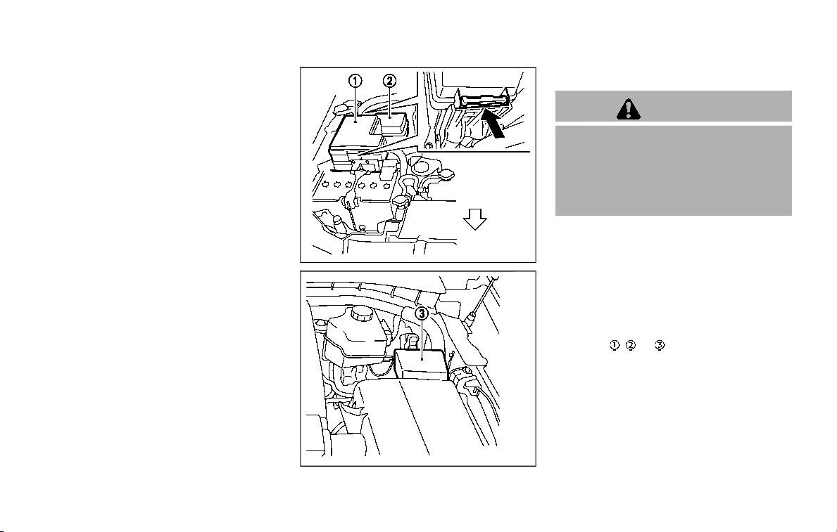
8-18 Do-it-yourself
each depression as the hydraulic
pressure decreases.
If the brakes do not operate properly,
have the brakes checked. It is recom-
mended that you visit a NISSAN dealer for
repair.
SDI2518
SDI2532
ENGINE COMPARTMENT
WARNING
Never use a fuse of a higher or lower
amperage rating than that specified
on the fuse box cover. This could
damage the electrical system or
electronic control units or cause a
fire.
If any electrical equipment does not
operate, check for an open fuse.
1. Be sure the ignition switch is pushed
to the OFF or LOCK position and the
headlight switch is turned to OFF.
2. Open the engine hood and remove
the cover on the battery.
3. Remove the fuse/fusible link holder
cover
, or .
4. Remove the fuse with the fuse puller.
FUSES
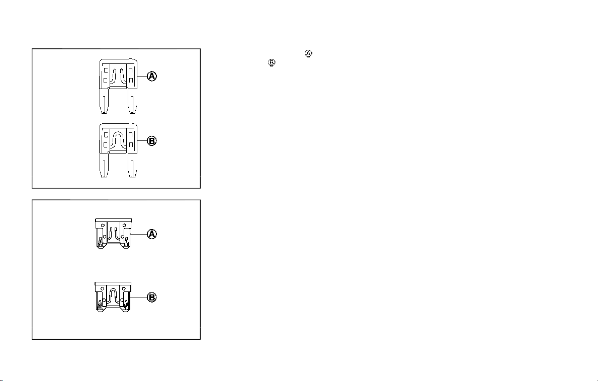
SDI1753
Type A (if so equipped)
SDI1754
Type B (if so equipped)
5. If the fuse is open , replace it with a
new fuse
. Spare fuses are stored in
the passenger compartment fuse box.
6. If a new fuse also opens, have the
electrical system checked and re-
paired. It is recommended you visit a
NISSAN dealer for this service.
Fusible links
If any electrical equipment does not
operate and fuses are in good condition,
check the fusible links. If any of these
fusible links are melted, replace only with
genuine NISSAN parts.
Do-it-yourself 8-19
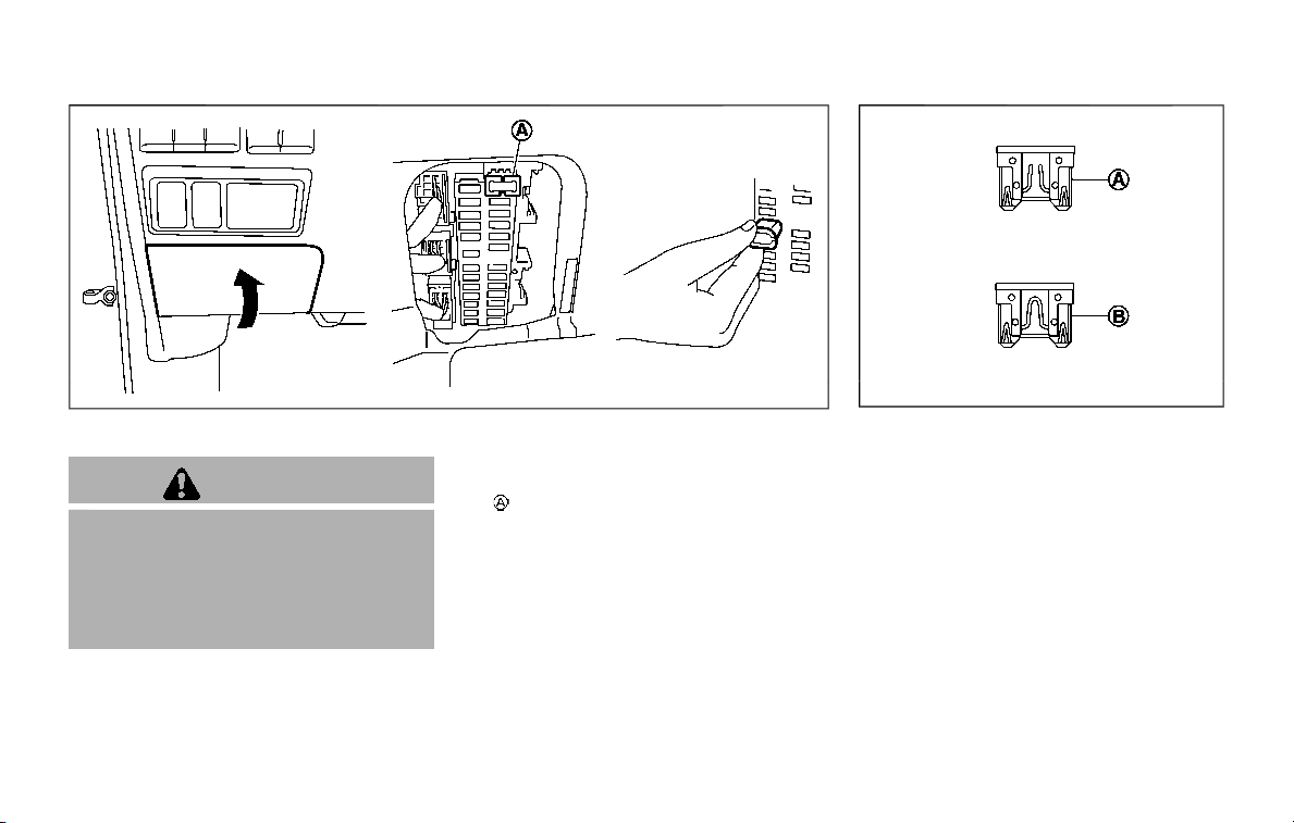
8-20 Do-it-yourself
JVM0200X
PASSENGER COMPARTMENT
WARNING
Never use a fuse of a higher or lower
amperage rating than that specified
on the fuse box cover. This could
damage the electrical system or
electronic control units or cause a
fire.
If any electrical equipment does not
operate, check for an open fuse.
1. Be sure the ignition switch is pushed
to the OFF or LOCK position and the
headlight switch is turned to OFF.
2. Open the fuse box lid.
3. Remove the fuse with the fuse puller
.
SDI1754
4. If the fuse is open, replace it with a
new fuse.
5. If a new fuse also opens, have the
electrical system checked and re-
paired. It is recommended you visit a
NISSAN dealer for this service. Spare
fuses are stored in the fuse box.
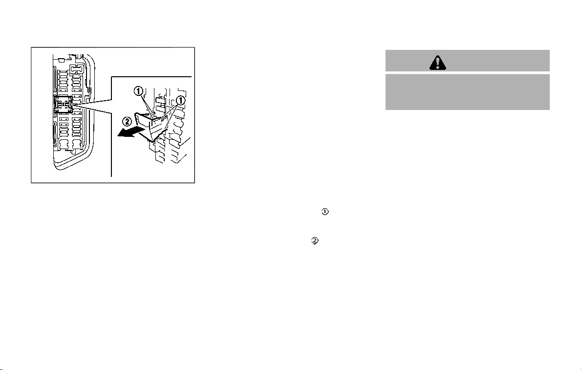
SDI2704
Extended storage fuse switch (if so
equipped)
To reduce battery drain, the extended
storage fuse switch comes from the
factory switched off. Prior to delivery of
your vehicle, the switch is pushed in
(switched on) and should always remain
on.
If the extended storage fuse switch is not
pushed in (switched on), the “SHIPPING
MODE ON, PUSH STORAGE FUSE” warning
may appear on the vehicle information
display (if so equipped). See “Vehicle
information display” (P.2-20).
If any electrical equipment does not
operate, remove the extended storage
fuse switch and check for an open fuse.
NOTE:
If the extended storage fuse switch
malfunctions or if the fuse is open, it is
not necessary to replace the switch. In
this case, remove the extended storage
fuse switch and replace it with a new
fuse of the same rating.
How to remove the extended storage
fuse switch:
1. To remove the extended storage fuse
switch, be sure the ignition switch is in
the OFF or LOCK position.
2. Be sure the headlight switch is in the
OFF position.
3. Remove the fuse box cover.
4. Pinch the locking tabs
found on
each side of the storage fuse switch.
5. Pull the storage fuse switch straight
out from the fuse box
.
CAUTION
Be careful not to allow children to
swallow the battery and removed
parts.
Do-it-yourself 8-21
INTELLIGENT KEY BATTERY REPLACEMENT

8-22 Do-it-yourself
SDI2451
Replace the battery as follows:
1. Release the lock knob at the back of
the Intelligent Key and remove the
mechanical key.
2. Insert a small screwdriver into the slit
of the corner and twist it to separate
the upper part from the lower part.
Use a cloth to protect the casing.
3. Replace the battery with a new one.
Recommended battery: CR2025 or
equivalent.
.
Do not touch the internal circuit
and electric terminals as it could
cause a malfunction.
.
Hold the battery by the edges.
Holding the battery across the
contact points will seriously deplete
the storage capacity.
.
Make sure that the + side faces the
bottom of the case.
SDI2452
4. Align the tips of the upper and lower
parts
, and then push them together
until it is securely closed
.
5. Push the buttons two or three times
to check its operation.
If you need any assistance for replace-
ment, it is recommended you visit a
NISSAN dealer for this service.
FCC Notice:
For USA:
This device complies with Part 15 of the
FCC Rules. Operation is subject to the
following two conditions: (1) This device
may not cause harmful interference,
and (2) this device must accept any
interference received, including inter-

ference that may cause undesired op-
eration.
Note: Changes or modifications not
expressly approved by the party re-
sponsible for compliance could void
the user’s authority to operate the
equipment.
For Canada:
This device complies with Industry Ca-
nada licence-exempt RSS standard(s).
Operation is subject to the following
two conditions: (1) this device may not
cause interference, and (2) this device
must accept any interference, including
interference that may cause undesired
operation of the device.
Do-it-yourself 8-23
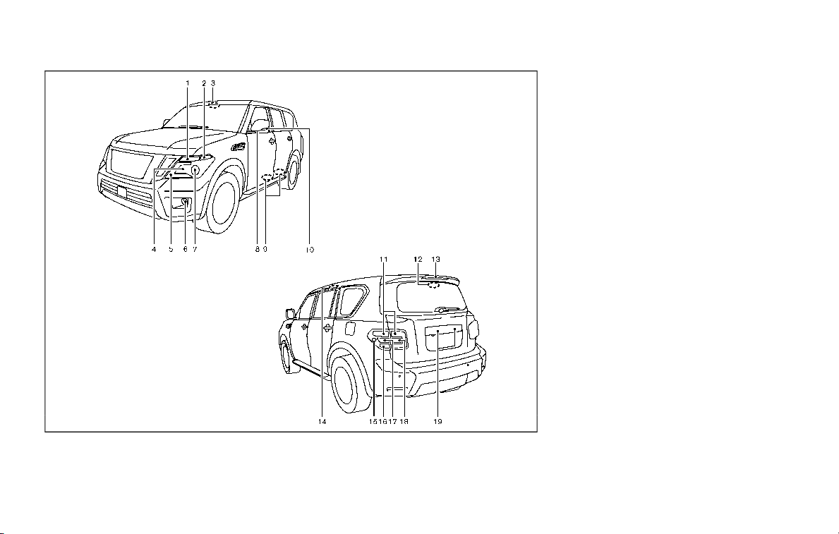
8-24 Do-it-yourself
JVM0727X
1. Front turn signal light
2. Front side marker light
3. Front map light
4. Headlight (high beam)
5. Front parking light/Daytime running light
6. Front fog light (if so equipped)
7. Headlight (low-beam)
8. Puddle light (if so equipped)
9. Step light (if so equipped)
10. Side turn signal light
11. Tail light
12. Cargo light
13. High-mounted stop light
14. Rear personal light
15. Rear side marker light
16. Stop light
17. Rear turn signal light
18. Back-up light
19. License plate light
HEADLIGHTS
Fog may temporarily form inside the lens
of the exterior lights in the rain or in a car
wash. A temperature difference between
the inside and the outside of the lens
causes the fog. This is not a malfunction.
If large drops of water collect inside the
lens, it is recommended you visit a NISSAN
dealer for this service.
LIGHTS
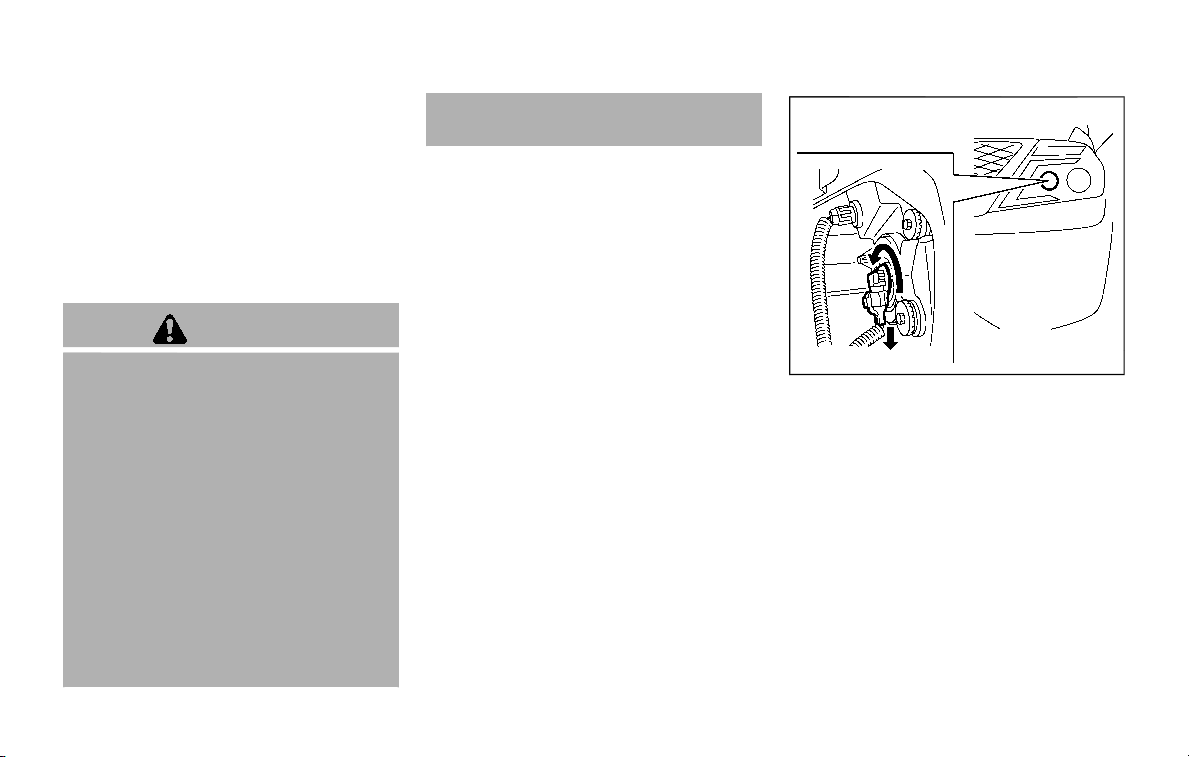
Replacing
LED headlight:
If replacement is required, it is recom-
mended you visit a NISSAN dealer for this
service.
Halogen headlight bulb:
The headlight (high-beam) is a semi-
sealed beam type which uses a replace-
able headlight (halogen) bulb.
CAUTION
. Do not leave the bulb out of the
headlight reflector for a long
period of time. Dust, moisture,
smoke, etc. entering the head-
light body may affect bulb per-
formance.
. High pressure halogen gas is
sealed inside the halogen bulb.
The bulb may break if the glass
envelope is scratched or the bulb
is dropped.
. Only touch the plastic base when
handling the bulb. Never touch
the glass envelope.
. Aiming is not necessary after
replacing the bulb. When aiming
adjustment is necessary, it is
recommended you visit a NISSAN
dealer for this service.
Use the same number and wattage as
originally installed as shown in the chart.
JVM0823X
The high-beam headlight can be replaced
from inside the engine compartment
without removing the headlight assem-
bly.
Do-it-yourself 8-25

8-26 Do-it-yourself
EXTERIOR AND INTERIOR LIGHTS
Item Wattage (W) Bulb No.
Headlight
High-beam (Halogen) 65
H9
Low-beam*
LED
—
Front turn signal light 28/8 7444NA
Fog light (if so equipped) 35 H8
Front parking light* LED —
Front side marker light* LED
—
Side turn signal light* LED
—
Rear combination light
tail* LED —
back-up 16 W16W
stop 21 W21W
side marker* LED —
turn signal 21 WY21W
License plate light 5 W5W
Puddle light* (if so equipped) LED —
Map light* LED —
Rear personal light 8 —
Cargo light 8 —
Vanity mirror light 1.8 —
Step light (if so equipped) 5 —
Footwell light* (if so equipped) 1.4
—
Glove box light* 1.4
—
High-mounted stop light* LED —
*: It is recommended you visit a NISSAN dealer for replacement.
NOTE: Always check with the Parts Depart-
ment at a NISSAN dealer for the latest
information about parts.
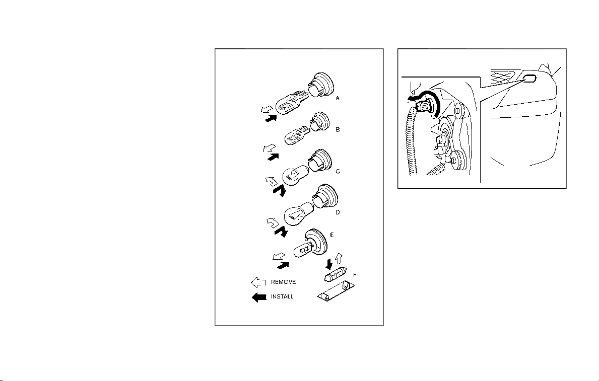
Replacement procedures
All other lights are either type A, B, C, D, E
or F. When replacing a bulb, first remove
the lens and/or cover.
SDI1679
JVM0825X
Front turn signal light
Do-it-yourself 8-27
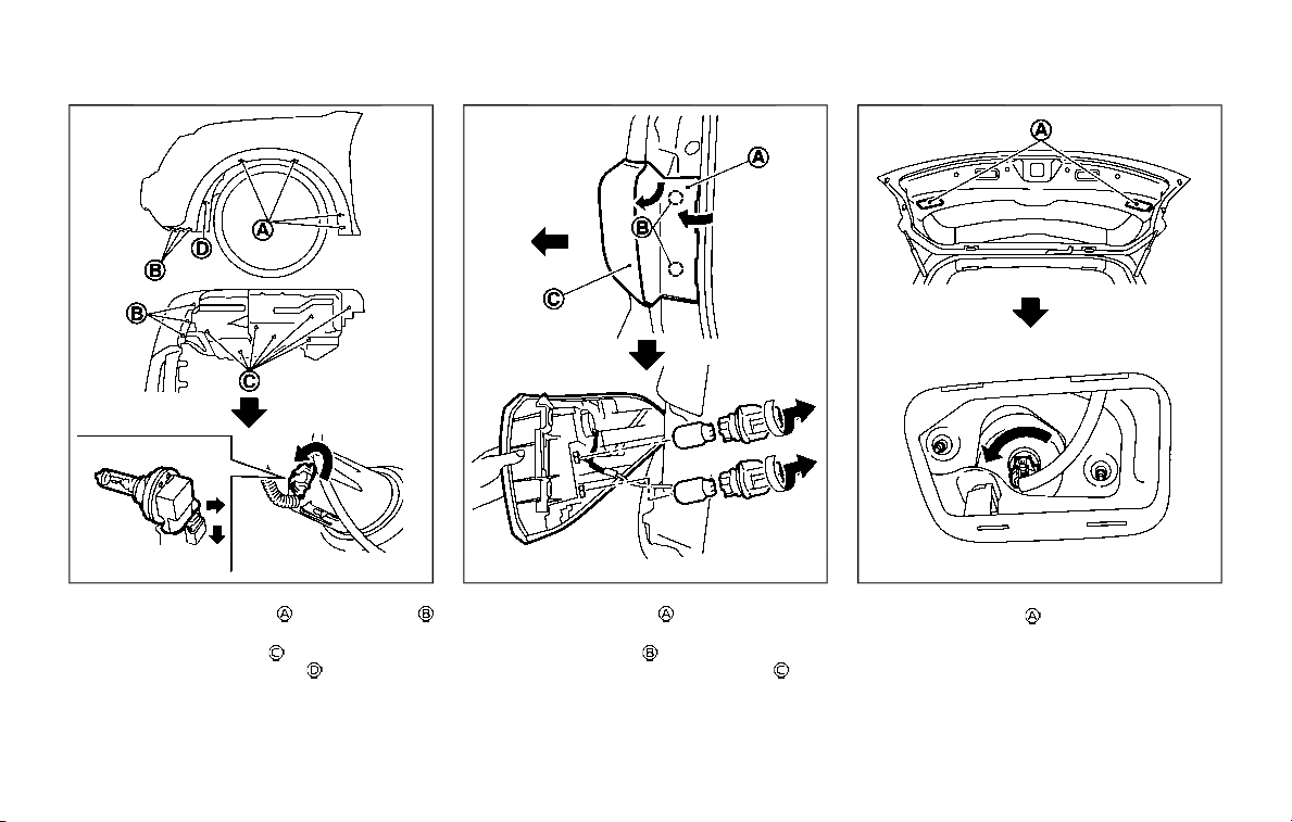
8-28 Do-it-yourself
SDI2628
Front fog light (if so equipped)
1. Remove the screws and the bolts
using a suitable tool.
2. Remove the clips
and remove the
wheel house inner cover
.
JVM0335X
Rear combination light (turn signal and stop)
1. Remove the cover by pulling it back-
ward.
2. Remove the bolts
, and gradually pry the
rear combination light whole unit
out-
ward.
SDI2524
Back-up light
Remove the cover on the inside of the
liftgate.
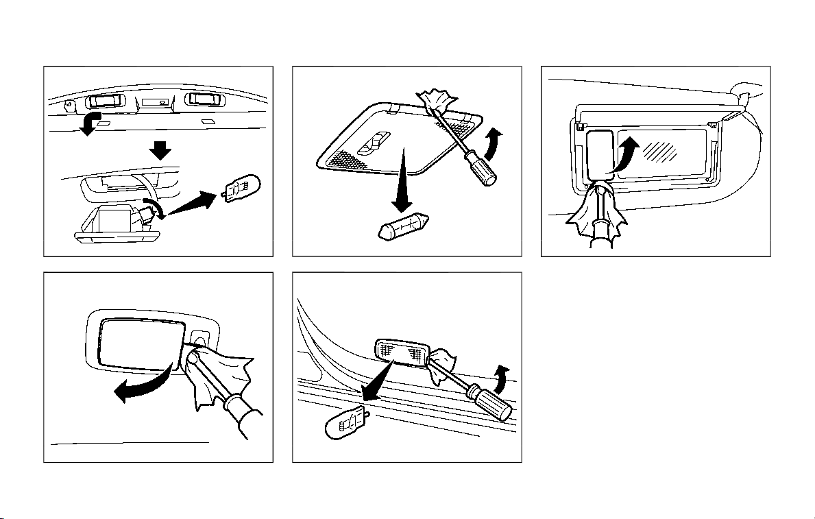
SDI2525
License plate light
SDI2031
Rear personal light
SDI1729
Cargo light
SDI2277
Step light (if so equipped)
SDI2032
Vanity mirror light
Do-it-yourself 8-29

8-30 Do-it-yourself
If you have a flat tire, see “Flat tire” (P.6-
3).
TIRE PRESSURE
Tire Pressure Monitoring System
(TPMS)
This vehicle is equipped with the Tire
Pressure Monitoring System (TPMS). It
monitors tire pressure of all tires except
the spare. When the low tire pressure
warning light is lit and the CHECK TIRE
PRESSURE warning appears in the vehicle
information display, one or more of your
tires is significantly under-inflated.
The TPMS will activate only when the
vehicle is driven at speeds above 16 MPH
(25 km/h). Also, this system may not
detect a sudden drop in tire pressure
(for example, a flat tire while driving).
For more details, see “Low tire pressure
warning light” (P.2-15), “Tire Pressure Mon-
itoring System (TPMS)” (P.5-5) and “Tire
Pressure Monitoring System (TPMS) ” (P.6-
3).
Tire inflation pressure
Check the pressure of the tires
(including the spare) often and al-
ways prior to long distance trips.
The recommended tire pressure
specifications are shown on the
Tire and Loading Information label
under the “Cold Tire Pressure”
heading. The Tire and Loading In-
formation label is affixed to the
driver side center pillar. Tire pres-
sures should be checked regularly
because:
. Most tires naturally lose air over
time.
. Tires can lose air suddenly when
driven over potholes or other
objects or if the vehicle strikes
a curb while parking.
The tire pressures should be
checked when the tires are cold.
The tires are considered COLD after
the vehicle has been parked for 3 or
more hours, or driven less than 1
mile (1.6 km) at moderate speeds.
TPMS with Easy Fill Tire Alert pro-
vides visual and audible signals
outside the vehicle for inflating the
tires to the recommended COLD
tire pressure. (See “TPMS with Easy
Fill Tire Alert” (P.5-8).)
Incorrect tire pressure, including
under inflation, may adversely
affect tire life and vehicle hand-
ling.
WARNING
. Improperly inflated tires can
fail suddenly and cause an
accident.
. The Gross Vehicle Weight
rating (GVWR) is located on
the F.M.V.S.S./C.M.V.S.S. cer-
tification label. The vehicle
weight capacity is indicated
on the Tire and Loading In-
formation label. Do not load
your vehicle beyond this ca-
pacity. Overloading your ve-
hicle may result in reduced
tire life, unsafe operating
conditions due to premature
tire failure, or unfavorable
WHEELS AND TIRES

handling characteristics and
could also lead to a serious
accident. Loading beyond
the specified capacity may
also result in failure of other
vehicle components.
. Before taking a long trip, or
whenever you heavily load
your vehicle, use a tire pres-
sure gauge to ensure that
the tire pressures are at the
specified level.
. For additional information
regarding tires, refer to “Im-
portant Tire Safety Informa-
tion” (US) or “Tire Safety
Information” (Canada) in the
Warranty Information Book-
let.
Do-it-yourself 8-31
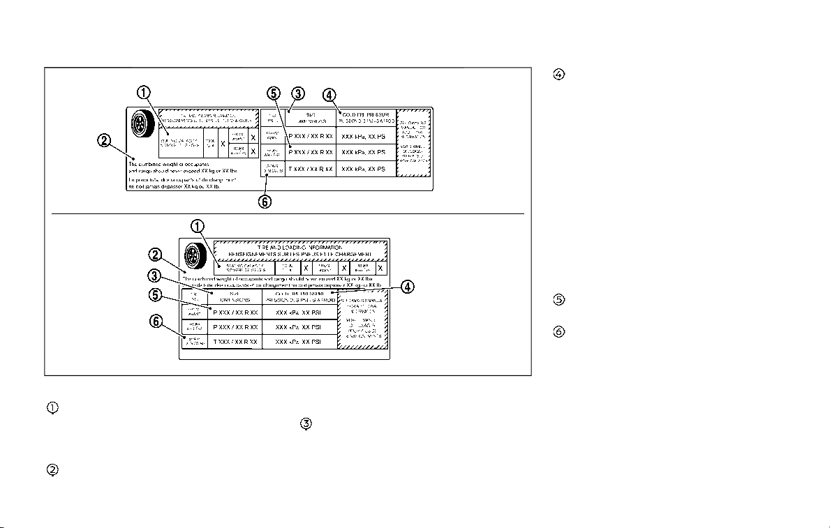
8-32 Do-it-yourself
SDI2496
Tire and Loading Information label
Seating capacity: The max-
imum number of occu-
pants that can be seated
in the vehicle.
Vehicle load limit: See “Ve-
hicle loading information”
(P.10-13).
Original size: The size of
the tires originally installed
on the vehicle at the fac-
tory.
Cold tire pressure: Inflate
the tires to this pressure
when the tires are cold.
Tires are considered COLD
after the vehicle has been
parked for 3 or more hours,
or driven less than 1 mile
(1.6 km) at moderate
speeds. The recommended
cold tire inflation is set by
the manufacturer to pro-
vide the best balance of
tire wear, vehicle handling,
driveability, tire noise, etc.,
up to the vehicle’s GVWR.
Tire size — see “Tire label-
ing” (P.8-34).
Spare tire size or compact
spare tire size (if so
equipped)
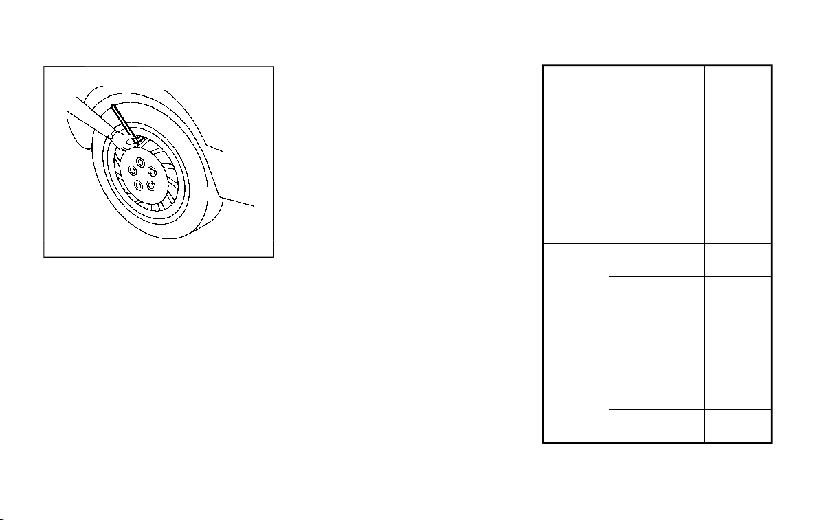
SDI1949
Checking the tire pressure
1. Remove the valve stem cap from
the tire.
2. Press the pressure gauge
squarely onto the valve stem.
Do not press too hard or force
the valve stem sideways, or air
will escape. If the hissing sound
of air escaping from the tire is
heard while checking the pres-
sure, reposition the gauge to
eliminate this leakage.
3. Remove the gauge.
4. Read the tire pressure on the
gauge stem and compare it to
the specification shown on the
Tire and Loading Information
label.
5. Add air to the tire as needed. If
too much air is added, press the
core of the valve stem briefly
with the tip of the gauge stem to
release pressure. Recheck the
pressure and add or release air
as needed.
6. Install the valve stem cap.
7. Check the pressure of all other
tires, including the spare.
SIZE
COLD
TIRE IN-
FLATION
PRES-
SURE
FRONT
ORIGI-
NAL
TIRE
265/70R18
116H
240 kPa,
35 PSI
P275/60R20
114H
240 kPa,
35 PSI
P275/50R22
111H
240 kPa,
35 PSI
REAR
ORIGI-
NAL
TIRE
265/70R18
116H
240 kPa,
35 PSI
P275/60R20
114H
240 kPa,
35 PSI
P275/50R22
111H
240 kPa,
35 PSI
SPARE
TIRE
265/70R18
116H
240 kPa,
35 PSI
265/70R18
116M
350 kPa,
51 PSI
275/60R20
115M
240 kPa,
35 PSI
Do-it-yourself 8-33
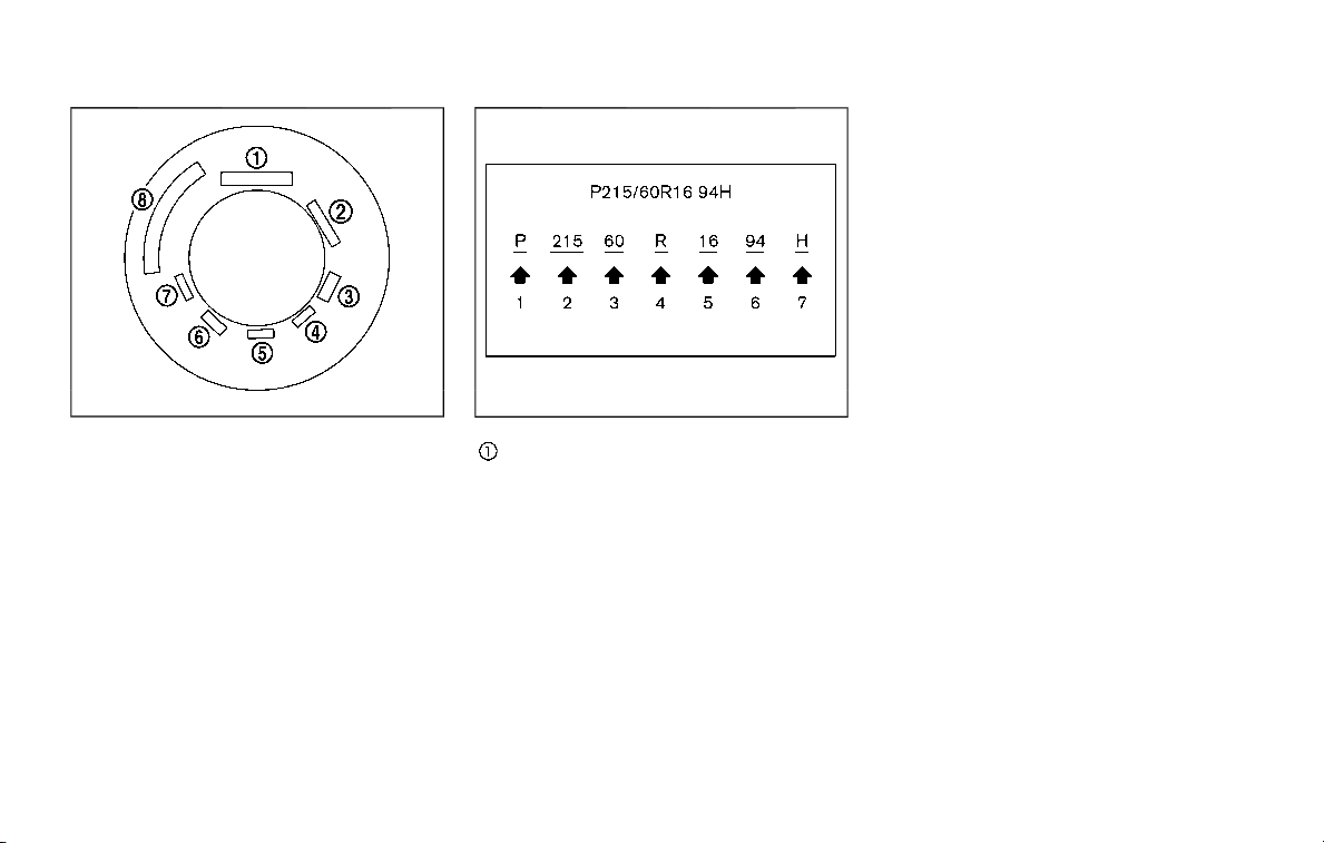
8-34 Do-it-yourself
SDI1575
Example
TIRE LABELING
Federal law requires tire manufac-
turers to place standardized infor-
mation on the sidewall of all tires.
This information identifies and de-
scribes the fundamental character-
istics of the tire and also provides
the tire identification number (TIN)
for safety standard certification.
The TIN can be used to identify
the tire in case of a recall.
SDI1606
Example
Tire size (example:
P215/60R16 94H)
1. P: The “P” indicates the tire is
designed for passenger vehicles.
(Not all tires have this informa-
tion.)
2. Three-digit number (215): This
number gives the width in milli-
meters of the tire from sidewall
edge to sidewall edge.
3. Two-digit number (60): This
number, known as the aspect
ratio, gives the tire’s ratio of
height to width.
4. R: The “R” stands for radial.
5. Two-digit number (16): This
number is the wheel or rim
diameter in inches.
6. Two- or three-digit number (94):
This number is the tire’s load
index. It is a measurement of
how much weight each tire can
support. You may not find this
information on all tires because
it is not required by law.
7. H: Tire speed rating. You should
not drive the vehicle faster than
the tire speed rating.
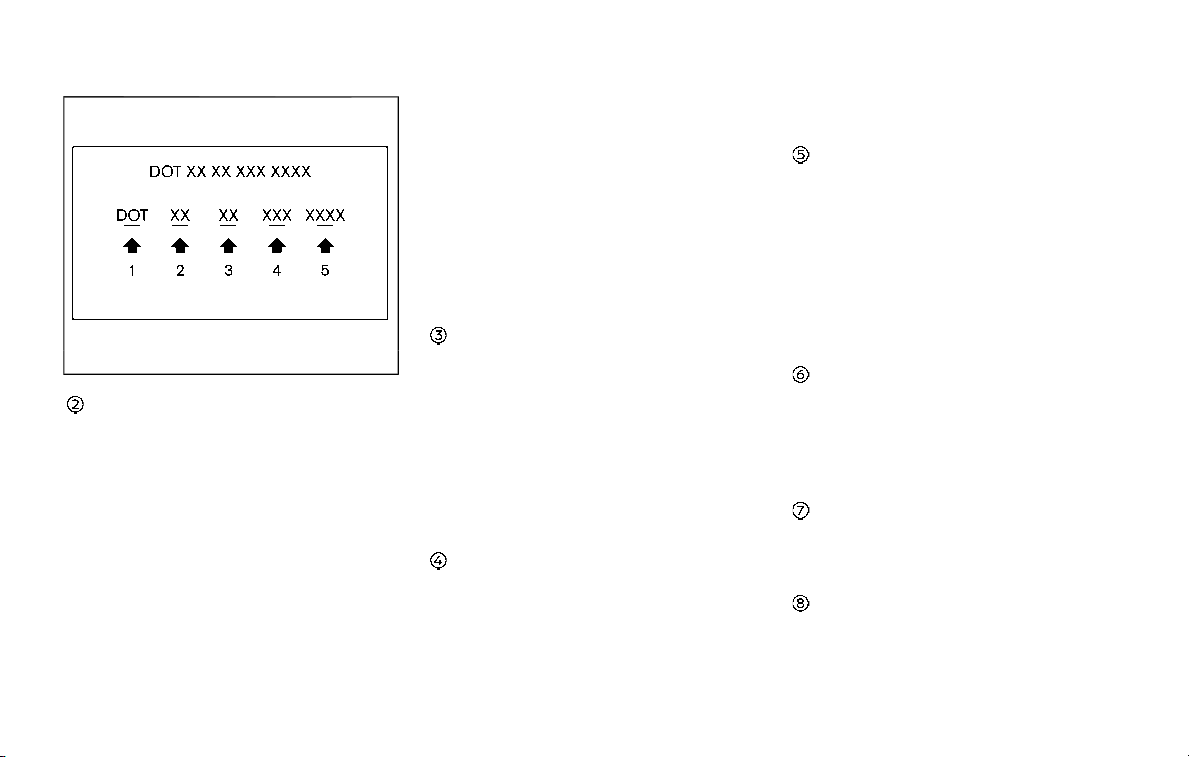
JVM0694X
Example
TIN (Tire Identification
Number) for a new tire
(example: DOT XX XX XXX
XXXX)
1. DOT: Abbreviation for the “De-
partment of Transportation”.
The symbol can be placed
above, below or to the left or
right of the Tire Identification
Number.
2. Two-digit code: Manufacturer’s
identification mark
3. Two-digit code: Tire size
4. Three-digit code: Tire type code
(Optional)
5. Four numbers represent the
week and year the tire was built.
For example, the numbers 3103
means the 31st week of 2003. If
these numbers are missing, then
look on the other sidewall of the
tire.
Tire ply composition and
material
The number of layers or
plies of rubber-coated fab-
ric in the tire.
Tire manufacturers also
must indicate the materials
in the tire, which include
steel, nylon, polyester, and
others.
Maximum permissible infla-
tion pressure
This number is the greatest
amount of air pressure
that should be put in the
tire. Do not exceed the
maximum permissible in-
flation pressure.
Maximum load rating
This number indicates the
maximum load in kilo-
grams and pounds that
can be carried by the tire.
When replacing the tires on
the vehicle, always use a
tire that has the same load
rating as the factory in-
stalled tire.
Term of “tubeless” or “tube
type”
Indicates whether the tire
requires an inner tube
(“tube type”) or not (“tube-
less”).
The word “radial”
The word “radial” is shown,
if the tire has radial struc-
ture.
Manufacturer or brand
name
Manufacturer or brand
name is shown.
Do-it-yourself 8-35

8-36 Do-it-yourself
Other tire-related terminology:
In addition to the many terms that
are defined throughout this sec-
tion, Intended Outboard Sidewall is
(1) the sidewall that contains a
whitewall, bears white lettering or
bears manufacturer, brand and/or
model name molding that is higher
or deeper than the same molding
on the other sidewall of the tire, or
(2) the outward facing sidewall of
an asymmetrical tire that has a
particular side that must always
face outward when mounted on a
vehicle.
TYPES OF TIRES
WARNING
. When changing or replacing tires,
be sure all four tires are of the
same type (Example: Summer, All
Season or Snow) and construc-
tion. A NISSAN dealer may be able
to help you with information
about tire type, size, speed rating
and availability.
. Replacement tires may have a
lower speed rating than the fac-
tory equipped tires, and may not
match the potential maximum
vehicle speed. Never exceed the
maximum speed rating of the
tire.
. Replacing tires with those not
originally specified by NISSAN
could affect the proper operation
of the TPMS.
. For additional information re-
garding tires, refer to “Important
Tire Safety Information” (US) or
“Tire Safety Information” (Cana-
da) in the Warranty Information
Booklet.
All season tires
NISSAN specifies all season tires on some
models to provide good performance all
year, including snowy and icy road con-
ditions. All Season tires are identified by
ALL SEASON and/or M&S (Mud and Snow)
on the tire sidewall. Snow tires have
better snow traction than All Season tires
and may be more appropriate in some
areas.
Summer tires
NISSAN specifies summer tires on some
models to provide superior performance
on dry roads. Summer tire performance is
substantially reduced in snow and ice.
Summer tires do not have the tire trac-
tion rating M&S on the tire sidewall.
If you plan to operate your vehicle in
snowy or icy conditions, NISSAN recom-
mends the use of SNOW tires or ALL
SEASON tires on all four wheels.
Snow tires
If snow tires are needed, it is necessary to
select tires equivalent in size and load
rating to the original equipment tires. If
you do not, it can adversely affect the
safety and handling of your vehicle.
Generally, snow tires will have lower
speed ratings than factory equipped tires
and may not match the potential max-
imum vehicle speed. Never exceed the
maximum speed rating of the tire.
If you install snow tires, they must be the
same size, brand, construction and tread
pattern on all four wheels.
For additional traction on icy roads,
studded tires may be used. However,
some U.S. states and Canadian provinces
prohibit their use. Check local, state and
provincial laws before installing studded
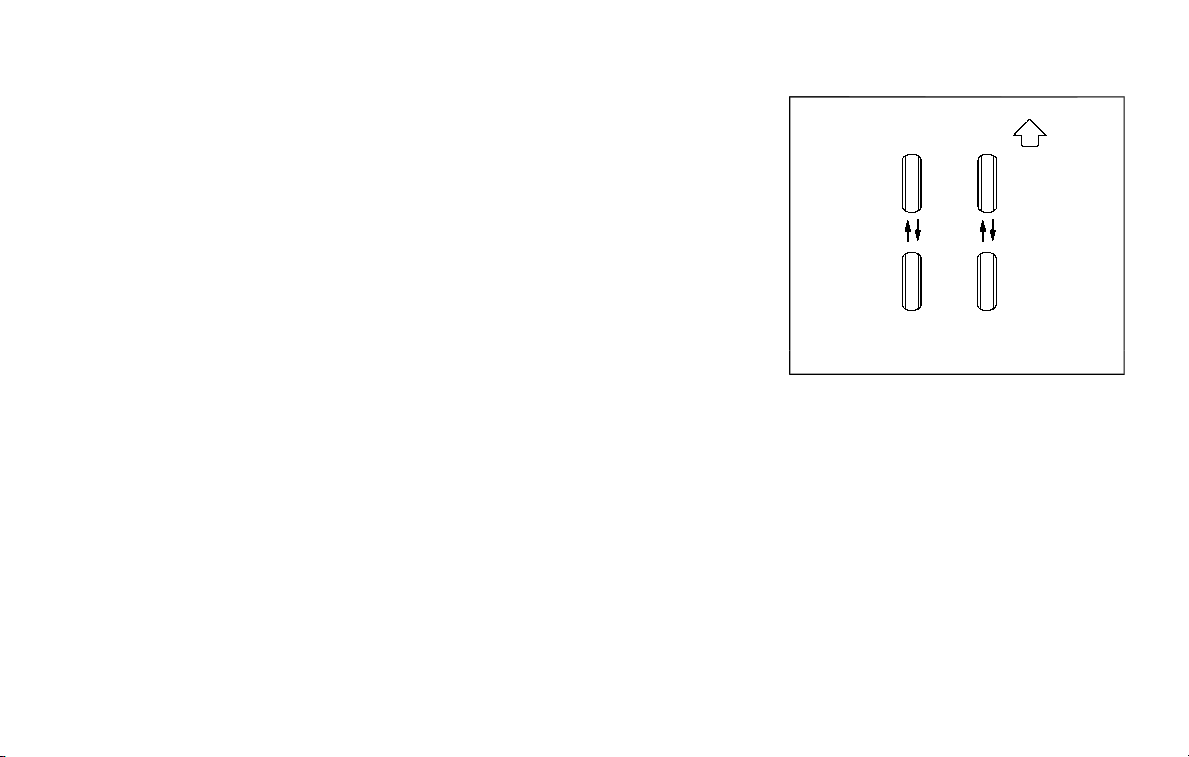
tires. Skid and traction capabilities of
studded snow tires, on wet or dry sur-
faces, may be poorer than that of non-
studded snow tires.
TIRE CHAINS
Use of tire chains may be prohibited
according to location. Check the local
laws before installing tire chains. When
installing tire chains, make sure they are
the proper size for the tires on your
vehicle and are installed according to
the chain manufacturer’s suggestions.
Use only SAE Class S chains. Class “S”
chains are used on vehicles with re-
stricted tire to vehicle clearance. Vehicles
that can use Class “S” chains are designed
to meet the SAE standard minimum
clearances between the tire and the
closest vehicle suspension or body com-
ponent required to accommodate the
use of a winter traction device (tire chains
or cables). The minimum clearances are
determined using the factory equipped
tire size. Other types may damage your
vehicle. Use chain tensioners when re-
commended by the tire chain manufac-
turer to ensure a tight fit. Loose end links
of the tire chain must be secured or
removed to prevent the possibility of
whipping action damage to the fenders
or underbody. If possible, avoid fully load-
ing your vehicle when using tire chains. In
addition, drive at a reduced speed. Other-
wise, your vehicle may be damaged and/
or vehicle handling and performance may
be adversely affected.
Tire chains must be installed only on
the rear wheels and not on the front
wheels.
Never install tire chains on the full-size
temporary use only spare tire (if so
equipped).
Do not use tire chains on dry roads.
Driving with tire chains in such conditions
can cause damage to the various me-
chanisms of the vehicle due to some
overstress.
SDI1662
CHANGING WHEELS AND TIRES
Tire rotation
NISSAN recommends rotating the
tires every 7,500 miles (12,000 km).
(See “Flat tire” (P.6-3) for tire repla-
cing procedures.)
As soon as possible, tighten the
wheel nuts to the specified torque
with a torque wrench.
Wheel nut tightening torque:
98 ft-lb (133 N·m)
The wheel nuts must be kept
tightened to the specification at
Do-it-yourself 8-37
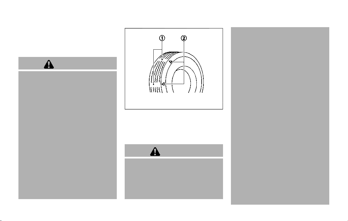
8-38 Do-it-yourself
all times. It is recommended that
wheel nuts be tightened to the
specification at each tire rotation
interval.
WARNING
. After rotating the tires,
check and adjust the tire
pressure.
. Retighten the wheel nuts
when the vehicle has been
driven for 600 miles (1,000
km) (also in cases of a flat
tire, etc.).
. Do not include the full-size
temporary use only spare
tire (if so equipped) in the
tire rotation.
. For additional information
regarding tires, refer to “Im-
portant Tire Safety Informa-
tion” (US) or “Tire Safety
Information” (Canada) in the
Warranty Information Book-
let.
SDI1663
1. Wear indicator
2. Wear indicator location
mark
Tire wear and damage
WARNING
. Tires should be periodically
inspected for wear, cracking,
bulging or objects caught in
the tread. If excessive wear,
cracks, bulging or deep cuts
are found, the tire(s) should
be replaced.
. The original tires have built-
in tread wear indicators.
When wear indicators are
visible, the tire(s) should be
replaced.
. Tires degrade with age and
use. Have tires, including the
spare, over 6 years old
checked by a qualified tech-
nician, because some tire
damage may not be ob-
vious. Replace the tires as
necessary to prevent tire
failure and possible perso-
nal injury.
. Improper service of the
spare tire may result in ser-
ious personal injury. If it is
necessary to repair the
spare tire, it is recom-
mended you visit a NISSAN
dealer for this service.
. For additional information
regarding tires, refer to “Im-
portant Tire Safety Informa-
tion” (US) or “Tire Safety

Information” (Canada) in the
Warranty Information Book-
let.
Replacing wheels and tires
When replacing a tire, use the same size,
tread design, speed rating and load
carrying capacity as originally equipped.
(See “Specifications” (P.10-7) for recom-
mended types and sizes of tires and
wheels.)
WARNING
. The use of tires other than those
recommended or the mixed use
of tires of different brands, con-
struction (bias, bias-belted or ra-
dial), or tread patterns can
adversely affect the ride, braking,
handling, ground clearance,
body-to-tire clearance, tire chain
clearance, speedometer calibra-
tion, headlight aim and bumper
height. Some of these effects
may lead to accidents and could
result in serious personal injury.
. For Two-Wheel Drive (2WD) mod-
els, if your vehicle was originally
equipped with 4 tires that were
the same size and you are only
replacing 2 of the 4 tires, install
the new tires on the rear axle.
Placing new tires on the front
axle may cause loss of vehicle
control in some driving condi-
tions and cause an accident and
personal injury.
. If the wheels are changed for any
reason, always replace with
wheels which have the same off-
set dimension. Wheels of a differ-
ent off-set could cause prema-
ture tire wear, degrade vehicle
handling characteristics and/or
interference with the brake
discs/drums. Such interference
can lead to decreased braking
efficiency and/or early brake
pad/shoe wear. See “Wheels and
tires” (P.10-8) for wheel off-set
dimensions.
. Since the spare tire is not
equipped with the TPMS, when a
spare tire is mounted or a wheel
is replaced, the TPMS will not
function and the low tire pressure
warning light will flash for ap-
proximately 1 minute. The light
will remain on after 1 minute.
Have your tires replaced and/or
TPMS system reset as soon as
possible. It is recommended you
visit a NISSAN dealer for these
services.
. Replacing tires with those not
originally specified by NISSAN
could affect the proper operation
of the TPMS.
. The TPMS sensor may be da-
maged if it is not handled cor-
rectly. Be careful when handling
the TPMS sensor.
. When replacing the TPMS sensor,
the ID registration may be re-
quired. It is recommended you
visit a NISSAN dealer for ID regis-
tration.
. Do not use a valve stem cap that
is not specified by NISSAN. The
valve stem cap may become
stuck.
. Be sure that the valve stem caps
are correctly fitted. Otherwise the
valve may be clogged up with dirt
and cause a malfunction or loss
of pressure.
. Do not install a damaged or
deformed wheel or tire even if it
has been repaired. Such wheels
or tires could have structural
damage and could fail without
warning.
Do-it-yourself 8-39

8-40 Do-it-yourself
. The use of retread tire is not
recommended.
. For additional information re-
garding tires, refer to “Important
Tire Safety Information” (US) or
“Tire Safety Information” (Cana-
da) in the Warranty Information
Booklet.
Four-Wheel Drive (4WD) models
CAUTION
. Always use tires of the same type,
size, brand, construction (bias,
bias-belted or radial), and tread
pattern on all four wheels. Failure
to do so may result in a circum-
ference difference between tires
on the front and rear axles which
will cause excessive tire wear and
may damage the transmission,
transfer case and differential
gears.
. ONLY use spare tires specified for
the 4WD model.
If excessive tire wear is found, it is
recommended that all four tires be re-
placed with tires of the same size, brand,
construction and tread pattern. The tire
pressure and wheel alignment should
also be checked and corrected as neces-
sary. It is recommended you visit a
NISSAN dealer for this service.
Wheel balance
Unbalanced wheels may affect vehicle
handling and tire life. Even with regular
use, wheels can get out of balance.
Therefore, they should be balanced as
required.
Wheel balance service should be per-
formed with the wheels off the vehicle.
Spin balancing the wheels on the vehi-
cle could lead to mechanical damage.
For additional information regarding tires,
refer to “Important Tire Safety Informa-
tion” (US) or “Tire Safety Information”
(Canada) in the NISSAN Warranty Infor-
mation Booklet.
Care of wheels
See “Cleaning exterior” (P.7-2) for details
about care of the wheels.
Spare tire
Since the spare tire is not equipped with
the TPMS, when a spare tire is mounted
(TEMPORARY USE ONLY or conventional),
the TPMS will not function.
Spare tire (FULL-SIZE TEMPORARY USE
ONLY spare tire) (Applies ONLY to vehi-
cles equipped with P275/50R22 or
P275/60R20 tires):
Observe the following precautions if the
full-size temporary use only spare tire
must be used, otherwise your vehicle
could be damaged or involved in an
accident.
WARNING
. The full-size temporary use only
spare tire should be used for
emergency use. It should be re-
placed with the standard tire at
the first opportunity to avoid
possible tire or differential da-
mage.
. Drive carefully while the spare tire
is installed. Avoid sharp turns and
abrupt braking while driving. The
vehicle driving performance may
be affected when driving on wet
or snow covered roads.

. When the spare tire is installed,
the following systems may not
work correctly.
— Tire Pressure Monitoring Sys-
tem (TPMS)
— Vehicle Dynamic Control (VDC)
System
. Periodically check spare tire in-
flation pressure. Always keep the
spare tire inflated to the pressure
specification shown on the Tire
and Loading Information label.
For Tire and Loading Information
label location, see “Tire and Load-
ing Information label” in the index
of this manual.
. With the spare tire installed do
not drive your vehicle at speeds
faster than 70 MPH (112 km/h).
. When driving on roads covered
with snow or ice, the spare tire
should be used on the front
wheels and original tire used on
the rear wheels (drive wheels).
Use tire chains only on the two
rear original tires.
. Do not use the spare tire on other
vehicles.
. Do not use more than one spare
tire at the same time.
CAUTION
Do not use tire chains on the spare
tire. Tire chains will not fit properly
and may cause damage to the vehi-
cle.
Do-it-yourself 8-41

8-42 Do-it-yourself
MEMO

9 Maintenance and schedules
Maintenance requirement ..................................................... 9-2
General maintenance ......................................................... 9-2
Scheduled maintenance .................................................. 9-2
Where to go for service .................................................... 9-2
General maintenance ................................................................ 9-2
Explanation of maintenance items ......................... 9-2
Explanation of scheduled maintenance items ...... 9-5
Emission control system maintenance ................ 9-5
Chassis and body maintenance ................................ 9-6
Maintenance schedules .......................................................... 9-7
Additional maintenance items for severe
operating conditions ........................................................ 9-7
Standard maintenance ........................................................... 9-7
Standard maintenance ................................................... 9-8
Maintenance under severe
driving conditions ..................................................................... 9-10
Maintenance log ........................................................................ 9-11

9-2 Maintenance and schedules
Some day-to-day and regular mainte-
nance is essential to maintain your vehi-
cle in good mechanical condition, as well
as its emission and engine performance.
It is the owner’s responsibility to make
sure that the scheduled maintenance, as
well as general maintenance, is per-
formed.
As the vehicle owner, you are the only one
who can ensure that your vehicle receives
the proper maintenance. You are a vital
link in the maintenance chain.
GENERAL MAINTENANCE
General maintenance includes those
items which should be checked during
normal day-to-day operation. They are
essential for proper vehicle operation. It is
your responsibility to perform these pro-
cedures regularly as prescribed.
Performing general maintenance checks
requires minimal mechanical skill and
only a few general automotive tools.
These checks or inspections can be done
by yourself, a qualified technician or, if you
prefer, a NISSAN dealer.
SCHEDULED MAINTENANCE
The maintenance items listed in this
section are required to be serviced at
regular intervals. However, under severe
driving conditions, additional or more
frequent maintenance will be required.
WHERE TO GO FOR SERVICE
If maintenance service is required or your
vehicle appears to malfunction, have the
systems checked and serviced. It is re-
commended you visit a NISSAN dealer for
this service.
NISSAN technicians are well-trained spe-
cialists and are kept up to date with the
latest service information through tech-
nical bulletins, service tips and training
programs. They are completely qualified
to work on NISSAN vehicles before work
begins.
If your vehicle is involved in a collision, it is
recommended that you ask your NISSAN
dealer where the nearest NISSAN Certified
Collision Center is located, or go to http://
collision.nissanusa.com.
You can be confident that a NISSAN
dealer’s service department can perform
the service needed to meet the mainte-
nance requirements on your vehicle.
During the normal day-to-day operation
of the vehicle, general maintenance
should be performed regularly as pre-
scribed in this section. If you detect any
unusual sounds, vibrations or smells, be
sure to check for the cause and have it
checked promptly. In addition, it is re-
commended you visit a NISSAN dealer if
you think that repairs are required.
When performing any checks or mainte-
nance work, closely observe “Mainte-
nance precautions” (P.8-2) of this manual.
EXPLANATION OF MAINTENANCE
ITEMS
Additional information on the following
items with “*” is found in the “8. Do-it-
yourself” section of this manual.
Outside the vehicle
The maintenance items listed here should
be performed from time to time, unless
otherwise specified.
Doors and engine hood: Check that all
doors and the engine hood, operate
properly. Also ensure that all latches lock
securely. Lubricate hinges, latches, latch
pins, rollers and links if necessary. Make
sure that the secondary latch keeps the
hood from opening when the primary
latch is released.
When driving in areas using road salt or
MAINTENANCE REQUIREMENT GENERAL MAINTENANCE

other corrosive materials, check lubrica-
tion frequently.
Lights*: Clean the headlights on a regular
basis. Make sure that the headlights, stop
lights, tail lights, turn signal lights, and
other lights are all operating properly and
installed securely. Also check headlight
aim.
Road wheel nuts (lug nuts)*: When
checking the tires, make sure no wheel
nuts are missing, and check for any loose
wheel nuts. Tighten if necessary.
Tire rotation*: Tires should be rotated
every 7,500 miles (12,000 km).
Tires*: Check the pressure with a gauge
often and always prior to long distance
trips. If necessary, adjust the pressure in
all tires, including the spare, to the
pressure specified. Check carefully for
damage, cuts or excessive wear.
Tire Pressure Monitoring System (TPMS)
transmitter components: Replace the
TPMS transmitter grommet seal, valve
core and cap when the tires are replaced
due to wear or age.
Wheel alignment and balance: If the
vehicle should pull to either side while
driving on a straight and level road, or if
you detect uneven or abnormal tire wear,
there may be a need for wheel alignment.
If the steering wheel or seat vibrates at
normal highway speeds, wheel balancing
may be needed.
For additional information regarding tires,
refer to “Important Tire Safety Informa-
tion” (US) or “Tire Safety Information”
(Canada) in the NISSAN Warranty Infor-
mation Booklet.
Windshield: Clean the windshield on a
regular basis. Check the windshield at
least every six months for cracks or other
damage. Have a damaged windshield
repaired by a qualified repair facility. It is
recommended that you have a damaged
windshield repaired by a NISSAN dealer, or
a NISSAN Certified Collision Center. To
locate a collision center in your area, refer
to http://collision.nissanusa.com.
Windshield wiper blades*: Check for
cracks or wear if they do not wipe
properly.
Inside the vehicle
The maintenance items listed here should
be checked on a regular basis, such as
when performing scheduled mainte-
nance, cleaning the vehicle, etc.
Accelerator pedal: Check the pedal for
smooth operation and make sure the
pedal does not catch or require uneven
effort. Keep the floor mat away from the
pedal.
Automatic transmission P (Park) me-
chanism: On a fairly steep hill, check that
your vehicle is held securely with the shift
lever in the P (Park) position without
applying any brakes.
Brake pedal: Check the pedal for smooth
operation. If the brake pedal suddenly
goes down further than normal, the pedal
feels spongy or the vehicle seems to take
longer to stop, have your vehicle checked
immediately. It is recommended you visit
a NISSAN dealer for this service. Keep the
floor mat away from the pedal.
Brakes: Check that the brakes do not pull
the vehicle to one side when applied.
Parking brake: Check the parking brake
operation regularly. The vehicle should be
securely held on a fairly steep hill with
only the parking brake applied. If the
parking brake needs adjusted, it is re-
commended you visit a NISSAN dealer for
this service.
Seats: Check seat position controls such
as seat adjusters, seatback recliner, etc. to
ensure they operate smoothly and that all
latches lock securely in every position.
Check that the head restraints move up
and down smoothly and that the locks (if
so equipped) hold securely in all latched
positions.
Seat belts: Check that all parts of the seat
Maintenance and schedules 9-3

9-4 Maintenance and schedules
belt system (for example, buckles, an-
chors, adjuster and retractors) operate
properly and smoothly, and are installed
securely. Check the belt webbing for cuts,
fraying, wear or damage.
Steering wheel: Check for changes in the
steering conditions, such as excessive
free play, hard steering or strange noises.
Warning lights and chimes: Make sure
that all warning lights and chimes are
operating properly.
Windshield defroster: Check that the air
comes out of the defroster outlets prop-
erly and in sufficient quantity when oper-
ating the heater or air conditioner.
Windshield wiper and washer*: Check
that the wipers and washer operate
properly and that the wipers do not
streak.
Under the hood and vehicle
The maintenance items listed here should
be checked periodically (for example,
each time you check the engine oil or
refuel).
Battery*: Check the fluid level in each cell.
It should be between the MAX and MIN
lines. Vehicles operated in high tempera-
tures or under severe condition require
frequent checks of the battery fluid level.
NOTE:
Care should be taken to avoid situations
that can lead to potential battery dis-
charge and potential no-start condi-
tions such as:
1. Installation or extended use of elec-
tronic accessories that consume
battery power when the engine is
not running (Phone chargers, GPS,
DVD players, etc.)
2. Vehicle is not driven regularly and/
or only driven short distances.
In these cases, the battery may need to
be charged to maintain battery health.
Brake fluid level*: Make sure that the
brake fluid level is between the MAX and
MIN lines on the reservoir.
Engine coolant level*: Check the coolant
level when the engine is cold.
Engine drive belts*: Make sure that no
belt is frayed, worn, cracked or oily.
Engine oil level*: Check the level after
parking the vehicle on a level spot and
turning off the engine. Wait more than 15
minutes for the oil to drain back into the
oil pan.
Exhaust system: Make sure there are no
loose supports, cracks or holes. If the
sound of the exhaust seems unusual or
there is a smell of exhaust fumes, im-
mediately have the exhaust system in-
spected. It is recommended you visit a
NISSAN dealer for this service. (See “Pre-
cautions when starting and driving” (P.5-
4) for exhaust gas (carbon monoxide).)
Fluid leaks: Check under the vehicle for
fuel, oil, water or other fluid leaks after the
vehicle has been parked for a while. Water
dripping from the air conditioner after use
is normal. If you should notice any leaks
or if gasoline fumes are evident, check for
the cause and have it corrected immedi-
ately.
Power steering fluid level* and lines:
Check the level when the fluid is cold, with
the engine off. Check the lines for proper
attachment, leaks, cracks, etc.
Radiator and hoses: Check the front of
the radiator and clean off any dirt, insects,
leaves, etc., that may have accumulated.
Make sure the hoses have no cracks,
deformation, rot or loose connections.
Underbody: The underbody is frequently
exposed to corrosive substances such as
those used on icy roads or to control
dust. It is very important to remove these
substances, otherwise rust will form on
the floor pan, frame, fuel lines and around
the exhaust system. At the end of winter,
the underbody should be thoroughly
flushed with plain water, being careful to
clean those areas where mud and dirt
may accumulate. For additional informa-

tion, see “Cleaning exterior” (P.7-2).
Windshield washer fluid*: Check that
there is adequate fluid in the reservoir.
The following descriptions are provided
to give you a better understanding of the
scheduled maintenance items that
should be regularly checked or replaced.
The maintenance schedule indicates at
which mileage/time intervals each item
requires service.
In addition to scheduled maintenance,
your vehicle requires that some items be
checked during normal day-to-day op-
eration. Refer to “General maintenance”
(P.9-2).
Items marked with “*” are recommended
by NISSAN for reliable vehicle operation.
You are not required to perform main-
tenance on these items in order to
maintain the warranties which come with
your vehicle. Other maintenance items
and intervals are required.
When applicable, additional information
can be found in the “8. Do-it yourself”
section of this manual.
NOTE:
NISSAN does not advocate the use of
non-OEM approved aftermarket flush-
ing systems and strongly advises
against performing these services on a
NISSAN product. Many of the aftermar-
ket flushing systems use non-OEM ap-
proved chemicals or solvents, the use of
which has not been validated by
NISSAN.
For recommended fuel, lubricants,
fluids, grease, and refrigerant, refer to
“Capacities and recommended fluids/
lubricants” (P.10-2) of this manual.
EMISSION CONTROL SYSTEM MAIN-
TENANCE
Drive belts*:
Check engine drive belts for wear, fraying
or cracking and for proper tension. Re-
place any damaged drive belts.
Engine air filter:
Replace at specified intervals. When driv-
ing for prolonged periods in dusty condi-
tions, check/replace the filter more
frequently.
Engine coolant*:
Replace coolant at the specified interval.
When adding or replacing coolant, be
sure to use only Genuine NISSAN Long
Life Antifreeze/Coolant (blue) or equiva-
lent with the proper mixture. (Refer to
“Engine cooling system” (P.8-4) to deter-
mine the proper mixture for your area.)
NOTE:
Mixing any other type of coolant or the
use of non-distilled water may reduce
the recommended service interval of
the coolant.
Maintenance and schedules 9-5
EXPLANATION OF SCHEDULED
MAINTENANCE ITEMS

9-6 Maintenance and schedules
Engine oil and oil filter:
Replace engine oil and oil filter at the
specified intervals. For recommended oil
grade and viscosity refer to “Capacities
and recommended fluids/lubricants”
(P.10-2).
Evaporative Emissions Control Vapor
Lines*:
Check vapor lines for leaks or looseness.
Tighten connections or replace parts as
necessary.
Fuel lines*:
Check the fuel hoses, piping and connec-
tions for leaks, looseness, or deterioration.
Tighten connections or replace parts as
necessary.
Spark plugs:
Replace at specified intervals. Install new
plugs of the type as originally equipped.
CHASSIS AND BODY MAINTENANCE
Brake lines and cables:
Visually inspect for proper installation.
Check for chafing, cracks, deterioration,
and signs of leaking. Replace any deterio-
rated or damaged parts immediately.
Brake pads and rotors:
Check for wear, deterioration and fluid
leaks. Replace any deteriorated or da-
maged parts immediately.
Exhaust system:
Visually inspect the exhaust pipes, muffler
and hangers for leaks, cracks, deteriora-
tion, and damage. Tighten connections or
replace parts as necessary.
Propeller shaft(s):
Check for damage, looseness, and grease
leakage.
In-cabin microfilter:
Replace at specified intervals. When driv-
ing for prolonged periods in dusty condi-
tions, replace the filter more frequently.
Steering gear and linkage, axle and
suspension parts:
Check for damage, looseness, and leak-
age of oil or grease. Under severe driving
conditions, inspect more frequently.
Tire rotation:
Tires should be rotated every 7,500 miles
(12,000 km). When rotating tires, check for
damage and uneven wear. Replace if
necessary.
Transmission fluid/oil, differential oil:
Visually inspect for signs of leakage at
specified intervals.
Off-road maintenance:
Check the following items frequently
whenever you drive off-road through
deep sand, mud or water:
. Brake pads and rotors
. Brake linings and drums
. Brake lines and hoses
. Differential, transmission and transfer
case oil
. Steering linkage
. Propeller shaft(s) and front drive
shafts
. Engine air filter
. Clutch housing drain (AWD only)

To help ensure smooth, safe and eco-
nomical driving, NISSAN provides two
maintenance schedules that may be
used, depending upon the conditions in
which you usually drive. These schedules
contain both distance and time intervals,
up to 120,000 miles (192,000 km)/96
months. For most people, the odometer
reading will indicate when service is
needed. However, if you drive very little,
your vehicle should be serviced at the
regular time intervals shown in the sche-
dule.
After 120,000 miles (192,000 km)/96
months, continue maintenance at the
same mileage/time intervals.
ADDITIONAL MAINTENANCE ITEMS
FOR SEVERE OPERATING CONDI-
TIONS
Additional maintenance items for se-
vere operating conditions; should be
performed on vehicles that are driven
under especially demanding conditions.
Additional maintenance items should be
performed if you primarily operate your
vehicle under the following conditions:
. Repeated short trips of less than 5
miles (8 km).
. Repeated short trips of less than 10
miles (16 km) with outside tempera-
tures remaining below freezing.
. Operating in hot weather in stop-and-
go “rush hour” traffic.
. Extensive idling and/or low speed
driving for long distances, such as
police, taxi or door-to-door delivery
use.
. Driving in dusty conditions.
. Driving on rough, muddy or salt
spread roads.
. Towing a trailer, or using a camper or
car-top carrier.
NOTE:
For vehicles operated in Canada, both
standard and severe maintenance
items should be performed at every
interval.
The following tables show the standard
maintenance schedule. Depending upon
weather and atmospheric conditions,
varying road surfaces, individual driving
habits and vehicle usage, additional or
more frequent maintenance may be re-
quired.
After 120,000 miles (192,000 km)/96
months, continue maintenance at the
same mileage/time intervals.
Maintenance and schedules 9-7
MAINTENANCE SCHEDULES STANDARD MAINTENANCE

9-8 Maintenance and schedules
STANDARD MAINTENANCE
Abbreviations: I = Inspect and correct or replace as necessary, R = Replace, L = Lubricate
MAINTENANCE OPERATION
Perform at number of miles, kilometers or months,
whichever comes first.
Miles × 1,000
(km × 1,000)
Months
MAINTENANCE INTERVAL
7.5
(12)
6
15
(24)
12
22.5
(36)
18
30
(48)
24
37.5
(60)
30
45
(72)
36
52.5
(84)
42
60
(96)
48
67.5
(108)
54
75
(120)
60
82.5
(132)
66
90
(144)
72
97.5
(156)
78
105
(168)
84
112.5
(180)
90
120
(192)
96
Air cleaner filter NOTE (1) R R R
R
Automatic transmission fluid NOTE (2)
Brake fluid$ RR R
R
Brake lines and cables II II I I I
I
Brake pads and rotors$ II II I I I
I
Drive belts NOTE (3) I* I* I* I*
I*
Engine coolant* NOTE (4)(5)
Engine oil & oil filter$ RRR R R R R R R R R R R R R
R
EVAP vapor lines & Fuel lines I* I* I*
I*
Exhaust system$ II I
I
Fuel filter NOTE (2)
In-cabin microfilter RR RR R R R
R
Intake & exhaust valve clearance NOTE (6)
Intelligent Key battery IRRRR
Propeller shaft & drive shaft boots (4WD models)$ II II I I I
I
Propeller shaft grease (4WD models) L L L L L L L
L
Spark plugs NOTE (7)
Replace every 105,000 miles (168,000 km)
Steering gear and linkage, axle and suspension parts$ II I
I
Tire rotation NOTE (8)
Transfer
fluid & differential gear oil See NOTE (9) I I I I I I I
I

NOTE:
Maintenance items with “$” should be performed more frequently according to “Maintenance under severe driving conditions”
(P.9-10).
(1) If operating mainly in dusty conditions, more frequent maintenance may be required.
(2) Periodic maintenance is not required.
(3) After 60,000 miles (96,000 km) or 48 months, inspect every 15,000 miles (24,000 km) or 12 months. Replace the drive belts if
found damaged.
(4) First replacement interval is 105,000 miles (168,000 km) or 84 months. After first replacement, replace every 75,000 miles
(120,000 km) or 60 months.
(5) Use only Genuine NISSAN Long Life Antifreeze/Coolant (blue) or equivalent with proper mixture ratio of 50% antifreeze and
50% demineralized or distilled water. Mixing any other type of coolant or the use of non-distilled water may reduce the life
expectancy of the factory fill coolant.
(6) Periodic maintenance is not required. However, if valve noise increases, inspect valve clearance.
(7) Replace spark plug when the plug gap exceeds 0.053 in (1.35 mm) even if within specified replacement mileage.
(8) Refer to “Tire rotation” under “General maintenance” (P.9-2).
(9) If towing a trailer, using a car-top carrier, or driving on rough or muddy roads, change (not just inspect) oil at every 20,000
miles (32,000 km) or 24 months.
*: Maintenance items and intervals with “*” are recommended by NISSAN for reliable vehicle operation. The owner need not
perform such maintenance in order to maintain the emission warranty or manufacturer recall liability. Other maintenance
items and intervals are required.
Maintenance and schedules 9-9

9-10 Maintenance and schedules
The maintenance intervals shown on the
preceding pages are for normal operating
conditions. If the vehicle is mainly oper-
ated under severe driving conditions as
shown below, more frequent mainte-
nance must be performed on the follow-
ing items as shown in the table.
Severe driving conditions
. Repeated short trips of less than 5
miles (8 km).
. Repeated short trips of less than 10
miles (16 km) with outside tempera-
tures remaining below freezing.
. Operating in hot weather in stop-and-
go “rush hour” traffic.
. Extensive idling and/or low speed
driving for long distances, such as
police, taxi or door-to-door delivery
use.
. Driving in dusty conditions.
. Driving on rough, muddy, or salt
spread roads.
. Towing a trailer, or using a camper or
car-top carrier
Maintenance operation: Inspect = Inspect
and correct or replace as necessary.
Maintenance item Maintenance opera-
tion
Maintenance interval
Brake fluid Replace Every 10,000 miles (16,000 km) or 12
months
Brake pads & rotors Inspect Every 5,000 miles (8,000 km) or 6
months
Engine oil & oil filter Replace Every 5,000 miles (8,000 km) or 6
months
Exhaust system Inspect Every 5,000 miles (8,000 km) or 6
months
Propeller shaft & drive shaft
boots (4WD models)
Inspect Every 5,000 miles (8,000 km) or 6
months
Steering gear & linkage, axle &
suspension parts
Inspect Every 5,000 miles (8,000 km) or 6
months
MAINTENANCE UNDER SEVERE
DRIVING CONDITIONS

7,500 Miles (12,000 km) or 6 Months
Dealer Name:
Date:
Mileage:
Dealer
Stamp:
15,000 Miles (24,000 km) or 12 Months
Dealer Name:
Date:
Mileage:
Dealer
Stamp:
22,500 Miles (36,000 km) or 18 Months
Dealer Name:
Date:
Mileage:
Dealer
Stamp:
30,000 Miles (48,000 km) or 24 Months
Dealer Name:
Date:
Mileage:
Dealer
Stamp:
37,500 Miles (60,000 km) or 30 Months
Dealer Name:
Date:
Mileage:
Dealer
Stamp:
45,000 Miles (72,000 km) or 36 Months
Dealer Name:
Date:
Mileage:
Dealer
Stamp:
52,500 Miles (84,000 km) or 42 Months
Dealer Name:
Date:
Mileage:
Dealer
Stamp:
60,000 Miles (96,000 km) or 48 Months
Dealer Name:
Date:
Mileage:
Dealer
Stamp:
67,500 Miles (108,000 km) or 54 Months
Dealer Name:
Date:
Mileage:
Dealer
Stamp:
Maintenance and schedules 9-11
MAINTENANCE LOG

9-12 Maintenance and schedules
75,000 Miles (120,000 km) or 60 Months
Dealer Name:
Date:
Mileage:
Dealer
Stamp:
82,500 Miles (132,000 km) or 66 Months
Dealer Name:
Date:
Mileage:
Dealer
Stamp:
90,000 Miles (144,000 km) or 72 Months
Dealer Name:
Date:
Mileage:
Dealer
Stamp:
97,500 Miles (156,000 km) or 78 Months
Dealer Name:
Date:
Mileage:
Dealer
Stamp:
105,000 Miles (168,000 km) or 84 Months
Dealer Name:
Date:
Mileage:
Dealer
Stamp:
112,500 Miles (180,000 km) or 90 Months
Dealer Name:
Date:
Mileage:
Dealer
Stamp:
120,000 Miles (192,000 km) or 96 Months
Dealer Name:
Date:
Mileage:
Dealer
Stamp:
________ Miles (________ km) or ____ Months
Dealer Name:
Date:
Mileage:
Dealer
Stamp:
________ Miles (________ km) or ____ Months
Dealer Name:
Date:
Mileage:
Dealer
Stamp:

________ Miles (________ km) or ____ Months
Dealer Name:
Date:
Mileage:
Dealer
Stamp:
________ Miles (________ km) or ____ Months
Dealer Name:
Date:
Mileage:
Dealer
Stamp:
________ Miles (________ km) or ____ Months
Dealer Name:
Date:
Mileage:
Dealer
Stamp:
________ Miles (________ km) or ____ Months
Dealer Name:
Date:
Mileage:
Dealer
Stamp:
________ Miles (________ km) or ____ Months
Dealer Name:
Date:
Mileage:
Dealer
Stamp:
________ Miles (________ km) or ____ Months
Dealer Name:
Date:
Mileage:
Dealer
Stamp:
________ Miles (________ km) or ____ Months
Dealer Name:
Date:
Mileage:
Dealer
Stamp:
________ Miles (________ km) or ____ Months
Dealer Name:
Date:
Mileage:
Dealer
Stamp:
________ Miles (________ km) or ____ Months
Dealer Name:
Date:
Mileage:
Dealer
Stamp:
Maintenance and schedules 9-13

9-14 Maintenance and schedules
________ Miles (________ km) or ____ Months
Dealer Name:
Date:
Mileage:
Dealer
Stamp:
________ Miles (________ km) or ____ Months
Dealer Name:
Date:
Mileage:
Dealer
Stamp:
________ Miles (________ km) or ____ Months
Dealer Name:
Date:
Mileage:
Dealer
Stamp:

10 Technical and consumer information
Capacities and
recommended fluids/lubricants .................................... 10-2
Fuel information .................................................................. 10-3
Engine oil and oil filter recommendation........ 10-5
Air conditioning system refrigerant and
lubricant recommendations ...................................... 10-6
Specifications ................................................................................ 10-7
Engine .......................................................................................... 10-7
Wheels and tires .................................................................. 10-8
Dimensions .............................................................................. 10-9
When traveling or registering in
another country ..................................................................... 10-10
Vehicle identification .......................................................... 10-10
Vehicle Identification Number
(VIN) plate .............................................................................. 10-10
Vehicle identification number
(chassis number) ............................................................. 10-10
Engine serial number ................................................... 10-11
F.M.V.S.S./C.M.V.S.S. certification label ............. 10-11
Emission control information label .................. 10-11
Tire and loading information label ................... 10-12
Air conditioner specification label ..................... 10-12
Installing front license plate ......................................... 10-12
Vehicle loading information ......................................... 10-13
Terms ..................................................................................... 10-13
Vehicle load capacity ................................................ 10-14
Securing the load ......................................................... 10-15
Loading tips ...................................................................... 10-16
Measurement of weights ....................................... 10-16
Towing a trailer ...................................................................... 10-17
Maximum load limits ................................................. 10-17
Maximum Gross Vehicle Weight (GVW)/
maximum Gross Axle Weight (GAW) .............. 10-19
Towing load/specification ..................................... 10-21
Towing safety ................................................................ 10-22
Flat towing ......................................................................... 10-29
Uniform tire quality grading ........................................ 10-30
Treadwear .......................................................................... 10-30
Traction AA, A, B and C ........................................... 10-30
Temperature A, B and C ......................................... 10-30
Emission control system warranty ......................... 10-31
Reporting safety defects ................................................ 10-31
Readiness for Inspection/Maintenance
(I/M) test ....................................................................................... 10-32
Event Data Recorders (EDR) ......................................... 10-33
Owner’s Manual/Service Manual
order information ................................................................. 10-34

10-2 Technical and consumer information
The following are approximate capacities. The actual refill capacities may be a little different. When refilling, follow the
procedure instructed in the “8. Do-it-yourself” section to determine the proper refill capacity.
Fluid type
Capacity (approximate)
Recommended Fluids/Lubricants
Metric
Measure
US
Measure
Imperial
Measure
Fuel 98.4 L 26 gal 21-5/8 gal ā See “Fuel information” (P.10-3).
Engine oil*1 With oil filter change 6.5 L 6-7/8 qt 5-3/4 qt ā Genuine “NISSAN Motor Oil 0W-20 SN” (or equivalent) is recom-
mended.
ā If the above motor oil (or engine oil) is not available, a synthetic
0W-20 GF-5 SN motor oil (or engine oil) may be used. Damage
caused by the use of motor oil (or engine oil) other than as
recommended is not covered under NISSAN’s New Vehicle
Limited Warranty.
For additional information, see “Engine oil and oil filter recom-
mendation” (P.10-5)
Drain and refill
*1: For additional informa-
tion, see “Changing engine
oil and filter” (P.8-6).
Without oil filter change 6.2 L 6-1/2 qt 5-1/2 qt
Engine coolant with reservoir 16.3 L 17-1/4 qt 14-3/8 qt ā Pre-diluted Genuine NISSAN Long Life Antifreeze/Coolant (blue)
or equivalent
Automatic transmission fluid (ATF) — — — ā Genuine NISSAN Matic S ATF
ā NISSAN recommends using Genuine NISSAN Matic S ATF ONLY in
NISSAN automatic transmissions. Do not mix with other fluids.
Using fluids that are not equivalent to Genuine NISSAN Matic S
ATF may damage the automatic transmission. Damage caused
by the use of fluids other than as recommended is not covered
under the NISSAN’s New Vehicle Limited Warranty.
Transfer fluid — — — ā Genuine NISSAN Transfer Fluid for ATX90A transfer
ā Using transfer fluid other than Genuine NISSAN Transfer Fluid
may damage the transfer, which is not covered by the NISSAN
New Vehicle Limited Warranty.
Front differential gear oil — — — ā Genuine NISSAN Differential Oil Hypoid Super GL-5 80W-90 or
equivalent conventional (non-synthetic) oil
Rear differential gear oil — — — ā Genuine NISSAN HYPOID FLUID · S1 GL-5 75W-80 or equivalent
Power steering fluid (PSF) Refill to the proper oil level according to the
instructions in the “8. Do-it-yourself” section.
ā Genuine NISSAN PSF or equivalent
ā DEXRON
TM
VI type ATF may also be used.
Brake fluid ā Genuine NISSAN Super Heavy Duty Brake Fluid*2 or equivalent
DOT 3
*2: Available in mainland U.S.A through a NISSAN dealer.
Multi-purpose grease — — — ā NLGI No. 2 (Lithium soap base)
Air conditioning system refrigerant — — — ā HFC-134a (R-134a)
ā For additional information, see “Vehicle identification” (P.10-10) for
air conditioner specification label.
Air conditioning system lubricants — — — ā NISSAN A/C System Oil Type S or exact equivalent
Window washer fluid — — — ā Genuine NISSAN Windshield Washer Concentrate Cleaner &
Antifreeze or equivalent
CAPACITIES AND RECOMMENDED
FLUIDS/LUBRICANTS

FUEL INFORMATION
VK56VD engine
Use unleaded regular gasoline with an
octane rating of at least 87 AKI (Anti-
Knock Index) number (Research octane
number 91).
CAUTION
. Using a fuel other than that spe-
cified could adversely affect the
emission control system, and
may also affect warranty cover-
age.
. Under no circumstances should a
leaded gasoline be used, because
this will damage the three-way
catalyst.
. Do not use E-15 or E-85 fuel in
your vehicle. Your vehicle is not
designed to run on E-15 or E-85
fuel. Using E-15 or E-85 fuel in a
vehicle not specifically designed
for E-15 or E-85 fuel can adversely
affect the emission control de-
vices and systems of the vehicle.
Damage caused by such fuel is
not covered by the NISSAN new
vehicle limited warranty.
. Do not use fuel that contains the
octane booster methylcyclopen-
tadienyl manganese tricarbonyl
(MMT). Using fuel containing
MMT may adversely affect vehicle
performance and vehicle emis-
sions. Not all fuel dispensers are
labeled to indicate MMT content,
so you may have to consult your
gasoline retailer for more details.
Note that Federal and California
laws prohibit the use of MMT in
reformulated gasoline.
. U.S. government regulations re-
quire ethanol dispensing pumps
to be identified by a small,
square, orange and black label
with the common abbreviation or
the appropriate percentage for
that region.
Gasoline specifications
NISSAN recommends using gasoline that
meets the World-Wide Fuel Charter
(WWFC) specifications where it is avail-
able. Many of the automobile manufac-
turers developed this specification to
improve emission system and vehicle
performance. Ask your service station
manager if the gasoline meets the
World-Wide Fuel Charter (WWFC) specifi-
cations.
Reformulated gasoline
Some fuel suppliers are now producing
reformulated gasolines. These gasolines
are specially designed to reduce vehicle
emissions. NISSAN supports efforts to-
wards cleaner air and suggests that you
use reformulated gasoline when avail-
able.
Gasoline containing oxygenates
Some fuel suppliers sell gasoline contain-
ing oxygenates such as ethanol, MTBE
and methanol with or without advertising
their presence. NISSAN does not recom-
mend the use of fuels of which the
oxygenate content and the fuel compat-
ibility for your NISSAN cannot be readily
determined. If in doubt, ask your service
station manager.
If you use oxygenate-blend gasoline,
please take the following precautions as
the usage of such fuels may cause vehicle
performance problems and/or fuel sys-
tem damage.
. The fuel should be unleaded and
have an octane rating no lower than
that recommended for unleaded
gasoline.
. If an oxygenate-blend, excepting a
methanol blend, is used, it should
Technical and consumer information 10-3

10-4 Technical and consumer information
contain no more than 10% oxyge-
nate. (MTBE may, however, be added
up to 15%.)
. E-15 fuel contains more than 10%
oxygenate. E-15 fuel will adversely
affect the emission control devices
and systems of the vehicle and
should not be used. Damage caused
by such fuel is not covered by the
NISSAN new vehicle limited war-
ranty.
. If a methanol blend is used, it should
contain no more than 5% methanol
(methyl alcohol, wood alcohol). It
should also contain a suitable
amount of appropriate cosolvents
and corrosion inhibitors. If not prop-
erly formulated with appropriate
cosolvents and corrosion inhibitors,
such methanol blends may cause
fuel system damage and/or vehicle
performance problems. At this time,
sufficient data is not available to
ensure that all methanol blends are
suitable for use in NISSAN vehicles.
If any undesirable driveability problems
such as engine stalling or hard hot
starting are experienced after using oxy-
genate-blend fuels, immediately change
to a non-oxygenate fuel or a fuel with a
low blend of MTBE.
Take care not to spill gasoline during
refueling. Gasoline containing oxyge-
nates can cause paint damage.
E-15 fuel
E-15 fuel is a mixture of approximately
15% fuel ethanol and 85% unleaded gaso-
line. E-15 can only be used in vehicles
designed to run on E-15 fuel. Do not use E-
15 in your vehicle. U.S. government reg-
ulations require fuel ethanol dispensing
pumps to be identified with small, square,
orange and black label with the common
abbreviation or the appropriate percen-
tage for that region.
E-85 fuel
E-85 fuel is a mixture of approximately
85% fuel ethanol and 15% unleaded gaso-
line. E-85 can only be used in a Flexible
Fuel Vehicle (FFV). Do not use E-85 fuel in
your vehicle. U.S. government regulations
require fuel ethanol dispensing pumps to
be identified by a small, square, orange
and black label with the common abbre-
viation or the appropriate percentage for
that region.
Fuel containing MMT
MMT, or methylcyclopentadienyl manga-
nese tricarbonyl, is an octane boosting
additive. NISSAN does not recommend
the use of fuel containing MMT. Such fuel
may adversely affect vehicle perfor-
mance, including the emissions control
system. Note that while some fuel pumps
label MMT content, not all do, so you may
have to consult your gasoline retailer for
more details.
Aftermarket fuel additives
NISSAN does not recommend the use of
any aftermarket fuel additives (Example:
fuel injector cleaner, octane booster, in-
take valve deposit removers, etc.) which
are sold commercially. Many of these
additives intended for gum, varnish or
deposit removal may contain active sol-
vent or similar ingredients that can be
harmful to the fuel system and engine.
Octane rating tips
Using unleaded gasoline with an octane
rating lower than recommended above
can cause persistent, heavy spark
knock. (Spark knock is a metallic rap-
ping noise.) If severe, this can lead to
engine damage. If you detect a persis-
tent heavy spark knock even when
using gasoline of the stated octane
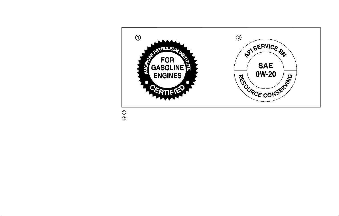
rating, or if you hear steady spark knock
while holding a steady speed on level
roads, it is recommended you have a
NISSAN dealer correct the condition.
Failure to correct the condition is mis-
use of the vehicle, for which NISSAN is
not responsible.
Incorrect ignition timing will result in
knocking, after-run or overheating. This
in turn may cause excessive fuel con-
sumption or damage to the engine. If any
of the above symptoms are encountered,
have your vehicle checked. It is recom-
mended you visit a NISSAN dealer for
servicing.
However, now and then you may notice
light spark knock for a short time while
accelerating or driving up hills. This is
no cause for concern, because you get
the greatest fuel benefit when there is
light spark knock for a short time under
heavy engine load.
JVT0342X
API certification mark
API service symbol
ENGINE OIL AND OIL FILTER RE-
COMMENDATION
Selecting the correct oil
It is essential to choose the correct grade,
quality, and viscosity engine oil to ensure
satisfactory engine life and performance,
see “Capacities and recommended fluids/
lubricants” (P.10-2). NISSAN recommends
the use of an energy conserving oil in
order to improve fuel economy.
Select only engine oils that meet the
American Petroleum Institute (API) certifi-
cation or International Lubricant Standar-
dization and Approval Committee (ILSAC)
certification and SAE viscosity standard.
These oils have the API certification mark
on the front of the container. Oils which
do not have the specified quality label
should not be used as they could cause
engine damage.
Oil additives
NISSAN does not recommend the use of
oil additives. The use of an oil additive is
not necessary when the proper oil type is
used and maintenance intervals are fol-
lowed.
Oil which may contain foreign matter or
has been previously used should not be
used.
Technical and consumer information 10-5

10-6 Technical and consumer information
Oil viscosity
The engine oil viscosity or thickness
changes with temperature. Because of
this, it is important that the engine oil
viscosity be selected based on the tem-
peratures at which the vehicle will be
operated before the next oil change.
Choosing an oil viscosity other than that
recommended could cause serious en-
gine damage.
Selecting the correct oil filter
Your new vehicle is equipped with a high-
quality genuine NISSAN oil filter. When
replacing, use the genuine oil filter or its
equivalent for the reason described in
change intervals.
Change intervals
The oil and oil filter change intervals for
your engine are based on the use of the
specified quality oils and filters. Oil and
filter other than the specified quality, or
oil and filter change intervals longer than
recommended could reduce engine life.
Damage to engines caused by improper
maintenance or use of incorrect oil and
filter quality and/or viscosity is not cov-
ered by the new NISSAN vehicle limited
warranties.
Your engine was filled with a high quality
engine oil when it was built. You do not
have to change the oil before the first
recommended change interval. Oil and
filter change intervals depend upon how
you use your vehicle.
AIR CONDITIONING SYSTEM RE-
FRIGERANT AND LUBRICANT RE-
COMMENDATIONS
The air conditioning system in your
NISSAN vehicle must be charged with
the refrigerant HFC-134a (R-134a) and
the lubricant, NISSAN A/C system oil
Type S or the exact equivalents.
CAUTION
The use of any other refrigerant or
lubricant may cause severe damage
to the air conditioning system and
may require the replacement of all
air conditioner system components.
The refrigerant HFC-134a (R-134a) in your
NISSAN vehicle will not harm the earth’s
ozone layer. Although this refrigerant
does not affect the earth’s atmosphere,
certain governmental regulations require
the recovery and recycling of any refrig-
erant during automotive air conditioning
system service. Your NISSAN dealer has
the trained technicians and equipment
needed to recover and recycle your air
conditioning system refrigerant.
It is recommended you visit a NISSAN
dealer when servicing your air condition-
ing system.

ENGINE
Model VK56VD
Type Gasoline, 4-cycle
Cylinder arrangement
8-cylinder, V-slanted at 90°
Bore × Stroke in (mm)
3.858 × 3.622 (98 × 92)
Displacement cu in (cm
3
) 338.78 (5,552)
Firing order 1-8-7-3-6-5-4-2
Idle speed rpm
See the emission control information
label on the underside of the hood.
Ignition timing (B.T.D.C.) degree/rpm
Spark plug Standard DILKAR7B11
Spark plug gap (Normal)
in (mm)
0.043 (1.1)
Camshaft operation Timing chain
This spark ignition system complies with the Canadian standard ICES-002.
STI0397B
Technical and consumer information 10-7
SPECIFICATIONS

10-8 Technical and consumer information
WHEELS AND TIRES
Road wheel
Type Size Offset in (mm)
Conventional
18 × 8J
1.18 (30)
20 × 8J
22 × 8J
Spare
18 × 8J
20 × 8J
Tire
Type Size Pressure PSI (kPa) [Cold]
Conventional
265/70R18 116H
35 (240)
P275/60R20 114H
P275/50R22 111H
Spare
265/70R18 116H
265/70R18 116M
51 (350)
275/60R20 115M
35 (240)

DIMENSIONS
Overall length in (mm) 208.9 (5,305)
Overall width in (mm) 79.9 (2,030)
Overall height
in (mm) 75.8 (1,925)
Front tread in (mm) 67.5 (1,715)
Rear tread
in (mm) 67.9 (1,725)
Wheelbase in (mm) 121.1 (3,075)
Technical and consumer information 10-9
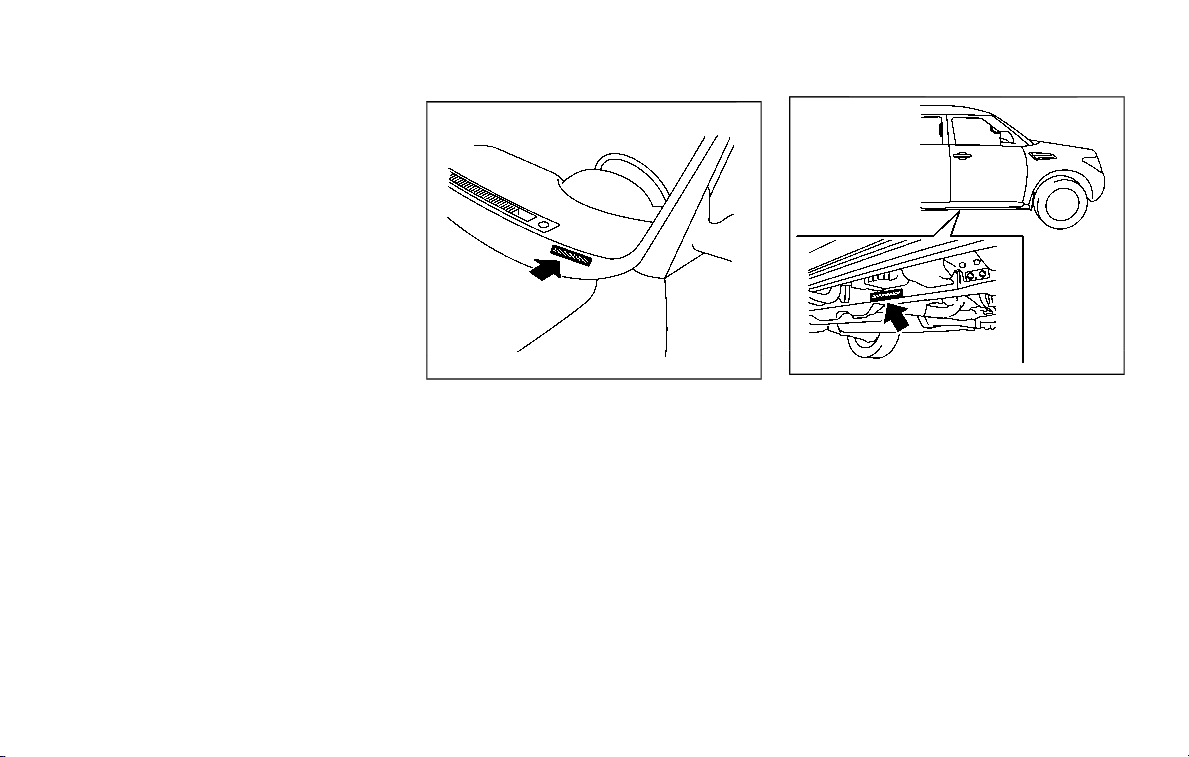
10-10 Technical and consumer information
If you plan to travel in another country,
you should first find out if the fuel
available is suitable for your vehicle’s
engine.
Using fuel with too low an octane rating
may cause engine damage. All gasoline
vehicles must be operated with unleaded
gasoline. Therefore, avoid taking your
vehicle to areas where appropriate fuel
is not available.
When transferring the registration of
your vehicle to another country, state,
province or district, it may be necessary
to modify the vehicle to meet local laws
and regulations.
The laws and regulations for motor
vehicle emission control and safety stan-
dards vary according to the country,
state, province or district; therefore, vehi-
cle specifications may differ.
When any vehicle is to be taken into
another country, state, province or dis-
trict and registered, its modifications,
transportation, and registration are the
responsibility of the user. NISSAN is not
responsible for any inconvenience that
may result.
STI0431
VEHICLE IDENTIFICATION NUMBER
(VIN) PLATE
The vehicle identification number plate is
attached as shown. This number is the
identification for your vehicle and is used
in the vehicle registration.
STI0708
VEHICLE IDENTIFICATION NUMBER
(chassis number)
The number is stamped as shown.
WHEN TRAVELING OR REGISTERING
IN ANOTHER COUNTRY
VEHICLE IDENTIFICATION
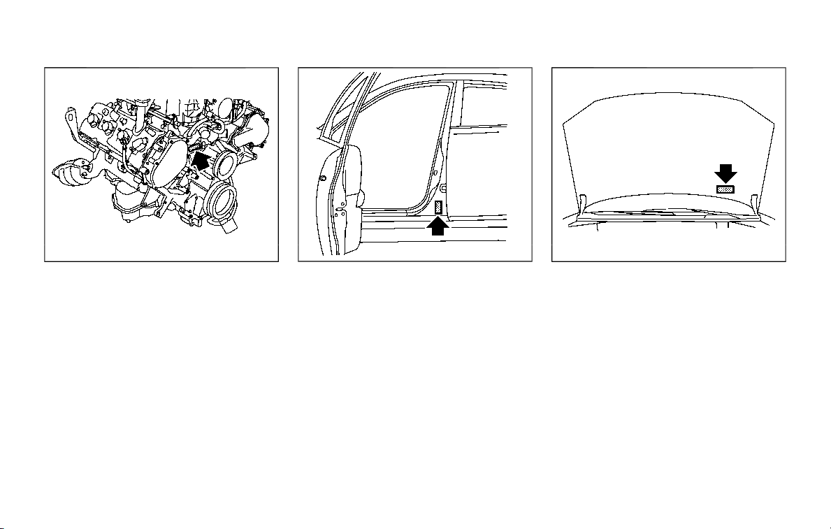
STI0709
ENGINE SERIAL NUMBER
The number is stamped on the engine as
shown.
STI0448
F.M.V.S.S./C.M.V.S.S. CERTIFICATION
LABEL
The Federal/Canadian Motor Vehicle
Safety Standards (F.M.V.S.S./C.M.V.S.S.)
certification label is affixed as shown. This
label contains valuable vehicle informa-
tion, such as: Gross Vehicle Weight Rat-
ings (GVWR), Gross Axle Weight Rating
(GAWR), month and year of manufacture,
Vehicle Identification Number (VIN), etc.
Review it carefully.
STI0738
EMISSION CONTROL INFORMATION
LABEL
The emission control information label is
attached as shown.
Technical and consumer information 10-11
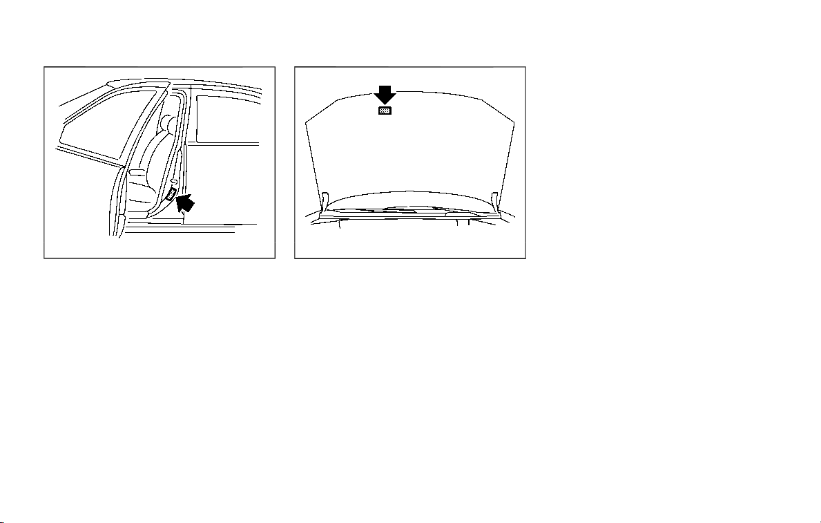
10-12 Technical and consumer information
STI0494
TIRE AND LOADING INFORMATION
LABEL
The cold tire pressure is shown on the
Tire and Loading Information label affixed
to the pillar as illustrated.
STI0739
AIR CONDITIONER SPECIFICATION
LABEL
The air conditioner specification label is
attached as shown.
To install the front license plate bracket
to your vehicle, it is recommended you
contact a NISSAN dealer.
INSTALLING FRONT LICENSE PLATE

WARNING
. It is extremely dangerous to
ride in a cargo area inside
the vehicle. In a collision,
people riding in these areas
are more likely to be ser-
iously injured or killed.
. Do not allow people to ride
in any area of vehicle that is
not equipped with seats and
seat belts.
. Be sure everyone in your
vehicle is in a seat and using
a seat belt properly.
TERMS
It is important to familiarize your-
self with the following terms before
loading your vehicle:
. Curb Weight (actual weight of
your vehicle) - vehicle weight
including: standard and optional
equipment, fluids, emergency
tools, and spare tire assembly.
This weight does not include
passengers and cargo.
. GVW (Gross Vehicle Weight) -
curb weight plus the combined
weight of passengers and cargo.
. GVWR (Gross Vehicle Weight Rat-
ing) - maximum total combined
weight of the unloaded vehicle,
passengers, luggage, hitch, trai-
ler tongue load and any other
optional equipment. This infor-
mation is located on the F.M.V.S.
S./C.M.V.S.S. label.
. GAWR (Gross Axle Weight Rating)
- maximum weight (load) limit
specified for the front or rear
axle. This information is located
on the F.M.V.S.S./C.M.V.S.S. label.
. GCWR (Gross Combined Weight
Rating) - The maximum total
weight rating of the vehicle,
passengers, cargo, and trailer.
. Vehicle Capacity Weight, Load
limit, Total load capacity - max-
imum total weight limit specified
of the load (passengers and
cargo) for the vehicle. This is
the maximum combined weight
of occupants and cargo that can
be loaded into the vehicle. If the
vehicle is used to tow a trailer,
the trailer tongue weight must
be included as part of the cargo
load. This information is located
on the Tire and Loading Infor-
mation label.
. Cargo capacity - permissible
weight of cargo, the weight of
total occupants weight sub-
tracted from the load limit.
Technical and consumer information 10-13
VEHICLE LOADING INFORMATION
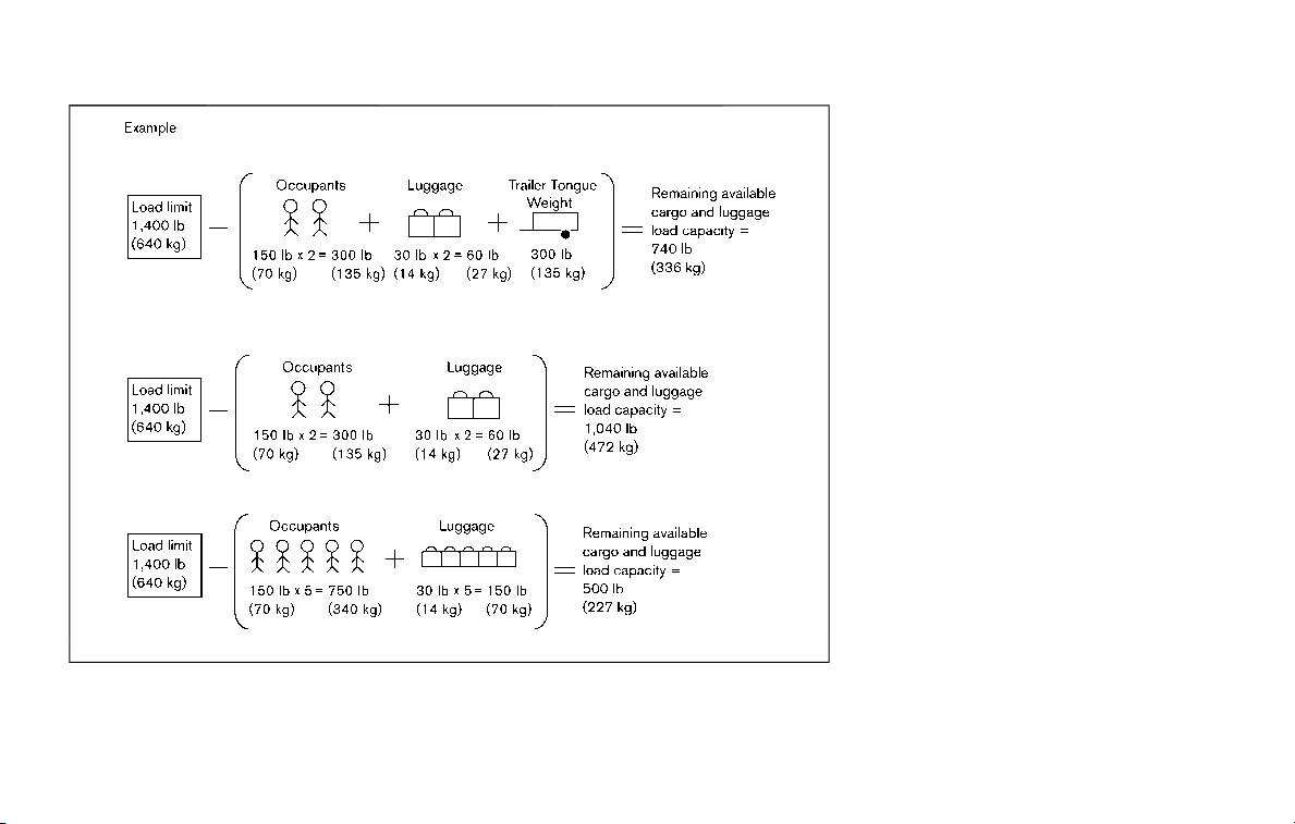
10-14 Technical and consumer information
STI0445
VEHICLE LOAD CAPACITY
Do not exceed the load limit of your
vehicle shown as “The combined
weight of occupants and cargo” on
the Tire and Loading Information
label. Do not exceed the number of
occupants shown as “Seating Ca-
pacity” on the Tire and Loading
Information label.
To get “the combined weight of
occupants and cargo”, add the
weight of all occupants, then add
the total luggage weight. Examples
are shown in the illustration.
Steps for determining correct load
limit
1. Locate the statement “The com-
bined weight of occupants and
cargo should never exceed XXX
kg or XXX lbs” on your vehicle’s
placard.
2. Determine the combined weight
of the driver and passengers
that will be riding in your vehicle.
3. Subtract the combined weight
of the driver and passengers
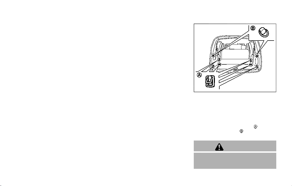
from XXX kg or XXX lbs.
4. The resulting figure equals the
available amount of cargo and
luggage load capacity. For ex-
ample, if the XXX amount equals
1400 lbs. and there will be five
150 lb. passengers in your vehi-
cle, the amount of available
cargo and luggage load capacity
is 650 lbs. (1400 − 750 (5 x 150) =
650 lbs) or (640 − 340 (5 x 70) =
300 kg.)
5. Determine the combined weight
of luggage and cargo being
loaded on the vehicle. That
weight may not safely exceed
the available cargo and luggage
load capacity calculated in Step
4.
6. If your vehicle will be towing a
trailer, load from your trailer will
be transferred to your vehicle.
Consult this manual to deter-
mine how this reduces the avail-
able cargo and luggage load
capacity of your vehicle.
Before driving a loaded vehicle,
confirm that you do not exceed
the Gross Vehicle Weight Rating
(GVWR) or the Gross Axle Weight
Rating (GAWR) for your vehicle. (See
“Measurement of weights” (P.10-16).)
Also check tires for proper inflation
pressures. See the Tire and Loading
Information label.
SIC4446
SECURING THE LOAD
There are tie down hooks located in the
cargo area as shown. The tie down hooks
can be used to secure cargo with ropes or
other types of straps.
Do not apply a total load of more than
22 lb (10 kg) to a single hook
or 7 lb (3
kg) to a single hook
when securing
cargo.
WARNING
. Properly secure all cargo with
ropes or straps to help prevent it
from sliding or shifting. Do not
Technical and consumer information 10-15

10-16 Technical and consumer information
place cargo higher than the seat-
backs. In a sudden stop or colli-
sion, unsecured cargo could
cause personal injury.
. The child restraint top tether
strap may be damaged by con-
tact with items in the cargo area.
Secure any items in the cargo
area. Your child could be seriously
injured or killed in a collision if the
top tether strap is damaged.
. Do not load your vehicle any
heavier than the GVWR or the
maximum front and rear GAWRs.
If you do, parts of your vehicle
can break, tire damage could
occur, or it can change the way
your vehicle handles. This could
result in loss of control and cause
personal injury.
LOADING TIPS
. The GVW must not exceed GVWR
or GAWR as specified on the F.M.
V.S.S./C.M.V.S.S. certification la-
bel.
. Do not load the front and rear
axle to the GAWR. Doing so will
exceed the GVWR.
WARNING
. Properly secure all cargo to
help prevent it from sliding
or shifting. Do not place
cargo higher than the seat-
backs. In a sudden stop or
collision, unsecured cargo
could cause personal injury.
. Do not load your vehicle any
heavier than the GVWR or
the maximum front and rear
GAWRs. If you do, parts of
your vehicle can break, tire
damage could occur, or it
can change the way your
vehicle handles. This could
result in loss of control and
cause personal injury.
. Overloading not only can
shorten the life of your ve-
hicle and the tire, but can
cause unsafe vehicle hand-
ling and long braking dis-
tance. This may cause a
premature tire failure, which
could result in a serious
accident and personal in-
jury. Failures caused by
overloading are not covered
by the vehicle’s warranty.
MEASUREMENT OF WEIGHTS
Secure loose items to prevent
weight shifts that could affect the
balance of your vehicle. When the
vehicle is loaded, drive to a scale
and weigh the front and the rear
wheels separately to determine
axle loads. Individual axle loads
should not exceed either of the
gross axle weight ratings (GAWR).
The total of the axle loads should
not exceed the gross vehicle
weight rating (GVWR). These ratings
are given on the vehicle certifica-
tion label. If weight ratings are
exceeded, move or remove items
to bring all weights below the
ratings.

WARNING
Overloading or improper loading of a
trailer and its cargo can adversely
affect vehicle handling, braking and
performance and may lead to acci-
dents.
CAUTION
. Do not tow a trailer or haul a
heavy load for the first 500 miles
(800 km). Your engine, axle or
other parts could be damaged.
. For the first 500 miles (800 km)
that you tow a trailer, do not drive
over 50 MPH (80 km/h) and do
not make starts at full throttle.
This helps the engine and other
parts of your vehicle wear in at
the heavier loads.
Your new vehicle was designed to be
used primarily to carry passengers and
cargo. Remember that towing a trailer
places additional loads on your vehicle’s
engine, drivetrain, steering, braking and
other systems.
A NISSAN Towing Guide (U.S. only) is
available on the website at
www.nissanusa.com. This guide includes
information on trailer towing capability
and the special equipment required for
proper towing.
MAXIMUM LOAD LIMITS
Maximum trailer loads
Never allow the total trailer load to
exceed the value specified in the “Towing
load/specification” (P.10-21). The total trai-
ler load equals trailer weight plus its
cargo weight.
. When towing a trailer load of 3,500
lbs (1,587 kg) or more, trailers with a
brake system MUST be used.
The maximum Gross Combined Weight
Rating (GCWR) should not exceed the
value specified in the following “Towing
Load/Specification” chart.
STI0541
The GCWR equals the combined weight of
the towing vehicle (including passengers
and cargo) plus the total trailer load.
Towing loads greater than these or using
improper towing equipment could ad-
versely affect vehicle handling, braking
and performance.
The ability of your vehicle to tow a trailer
is not only related to the maximum trailer
loads, but also the places you plan to tow.
Tow weights appropriate for level high-
way driving may have to be reduced on
very steep grades or for low traction
situations (for example, on slippery boat
ramps).
Temperature conditions can also affect
Technical and consumer information 10-17
TOWING A TRAILER
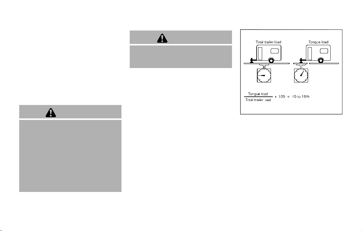
10-18 Technical and consumer information
towing. For example, towing a heavy
trailer in high outside temperatures on
graded roads can affect engine perfor-
mance and cause overheating. The trans-
mission high fluid temperature and
engine protection mode, which helps
reduce the chance of transmission and
engine damage, could activate and auto-
matically decrease engine power. Vehicle
speed may decrease under high load.
Plan your trip carefully to account for
trailer and vehicle load, weather and road
conditions.
WARNING
Overheating can result in reduced
engine power and vehicle speed.
The reduced speed may be lower
than other traffic, which could in-
crease the chance of a collision. Be
especially careful when driving. If the
vehicle cannot maintain a safe driv-
ing speed, pull to the side of the road
in a safe area. Allow the engine to
cool and return to normal operation.
See “If your vehicle overheats” (P.6-
14).
CAUTION
Vehicle damage resulting from im-
proper towing procedures is not
covered by NISSAN warranties.
STI0542
Tongue load
When using a weight carrying or a weight
distributing hitch, keep the tongue load
between 10 to 15% of the total trailer load
or use the trailer tongue load specified by
the trailer manufacturer. The tongue load
must be within the maximum tongue
load limits shown in the following “Towing
Load/Specification” chart. If the tongue
load becomes excessive, rearrange cargo
to allow for proper tongue load.
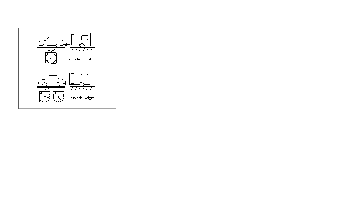
TI1012M
MAXIMUM GROSS VEHICLE WEIGHT
(GVW)/MAXIMUM GROSS AXLE
WEIGHT (GAW)
The GVW of the towing vehicle must not
exceed the Gross Vehicle Weight Rating
(GVWR) shown on the F.M.V.S.S./C.M.V.S.S.
certification label. The GVW equals the
combined weight of the unloaded vehicle,
passengers, luggage, hitch, trailer tongue
load and any other optional equipment. In
addition, front or rear GAW must not
exceed the Gross Axle Weight Rating
(GAWR) shown on the F.M.V.S.S./C.M.V.S.S.
certification label.
Towing capacities are calculated assum-
ing a base vehicle with driver and any
options required to achieve the rating.
Additional passengers, cargo and/or op-
tional equipment, such as the trailer hitch,
will add weight to the vehicle and reduce
your vehicle’s maximum towing capacity
and trailer tongue load.
The vehicle and trailer need to be
weighed to confirm the vehicle is within
the GVWR, Front GAWR, Rear GAWR, Gross
Combined Weight Rating (GCWR) and
Towing capacity.
All vehicle and trailer weights can be
measured using platform type scales
commonly found at truck stops, highway
weigh stations, building supply centers or
salvage yards.
To determine the available payload capa-
city for tongue/king pin load, use the
following procedure.
1. Locate the GVWR on the F.M.V.S.S./C.
M.V.S.S. certification label.
2. Weigh your vehicle on the scale with
all of the passengers and cargo that
are normally in the vehicle when
towing a trailer.
3. Subtract the actual vehicle weight
from the GVWR. The remaining
amount is the available maximum
tongue/king pin load.
To determine the available towing capa-
city, use the following procedure.
1. Find the GCWR for your vehicle on the
“Towing Load/Specification” chart
found later in this section.
2. Subtract the actual vehicle weight
from the GCWR. The remaining
amount is the available maximum
towing capacity.
To determine the Gross Trailer Weight,
weigh your trailer on a scale with all
equipment and cargo, that are normally
in the trailer when it is towed. Make sure
the Gross trailer weight is not more than
the Gross Trailer Weight Rating shown on
the trailer and is not more than the
calculated available maximum towing
capacity.
Also weigh the front and rear axles on the
scale to make sure the Front Gross Axle
Weight and Rear Gross Axle Weight are
not more than Front Gross Axle Weight
and Rear Gross Axle Weight on the F.M.V.S.
S./C.M.V.S.S. certification label. The cargo
in the trailer and vehicle may need to be
moved or removed to meet the specified
ratings.
Example:
. Gross Vehicle Weight (GVW) as
weighed on a scale - including pas-
sengers, cargo and hitch - 5,822 lb.
(2,641 kg).
Technical and consumer information 10-19

10-20 Technical and consumer information
. Gross Vehicle Weight Rating (GVWR)
from F.M.V.S.S./C.M.V.S.S. certification
label - 7,300 lb. (3,311 kg).
. Gross Combined Weight Rating
(GCWR) from “Towing Load/Specifica-
tion” chart - 14,700 lb. (6,668 kg).
. Maximum Trailer towing capacity
from “Towing Load/Specification”
chart - 8,500 lb. (3,856 kg).
7,300 lb. (3,311 kg)
GVWR
− 5,822 lb. (2,641 kg)
GVW
= 1,478 lb. (670 kg)
Available for tongue
weight
14,700 lb. (6,668 kg)
GCWR
− 5,822 lb. (2,641 kg)
GVW
= 8,878 lb. (4,027 kg)
Capacity available for
towing
1,478 lb. (670 kg) /
Available tongue
weight
8,878 lb. (4,027 kg)
Available capacity
= 11 % tongue weight
The available towing capacity may be less
than the maximum towing capacity due
to the passenger and cargo load in the
vehicle.
Remember to keep trailer tongue weight
between 10 - 15% of the trailer weight or
within the trailer tongue load specifica-
tion recommended by the trailer manu-
facturer. If the tongue load becomes
excessive, rearrange the cargo to obtain
the proper tongue load. Do not exceed
the maximum tongue weight specifica-
tion shown in the “Towing load/specifica-
tion” chart even if the calculated available
tongue weight is greater than 15%. If the
calculated tongue weight is less than 10%,
reduce the total trailer weight to match
the available tongue weight.
Always verify that available capacities are
within the required ratings.

TOWING LOAD/SPECIFICATION
WARNING
The towing capacities provided in
this manual are for general reference
only. The safe towing capacity of
your vehicle is affected by dealer
and factory installed options and
passenger and cargo loads. You
must weigh the vehicle and trailer
as described in this manual to de-
termine the actual vehicle towing
capacity. Do not exceed the pub-
lished maximum towing capacity, or
the GCWR or the GVWR shown on the
F.M.V.S.S./C.M.V.S.S. certification la-
bel. Doing so can result in an acci-
dent causing serious personal injury
or property damage.
Towing load/specification chart
Axle Type
Two-Wheel Drive (2WD)
Four-Wheel Drive (4WD)
Maximum Towing Capacity*1, *2 8,500 lb (3,856 kg)
Maximum Tongue Load 850 lb (385 kg)
Maximum Gross Combined Weight Rat-
ing
14,450 lb (6,554 kg)
14,700 lb (6,668 kg)
1: The towing capacity values are calculated assuming a base vehicle with driver and any
options required to achieve the rating. Additional passengers, cargo and/or optional
equipment will add weight to the vehicle and reduce your vehicle’s maximum towing
capacity.
2: Use of a weight-distributing hitch system is recommended when towing over 5,000 lb (2,267
kg).
Technical and consumer information 10-21
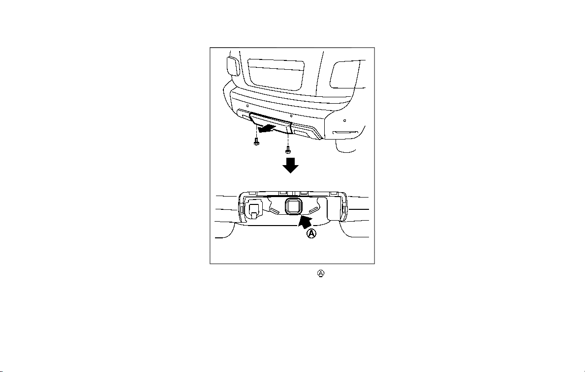
10-22 Technical and consumer information
TOWING SAFETY
Trailer hitch
Your vehicle is equipped with a trailer tow
package. The trailer tow package in-
cludes a receiver-type frame mounted
hitch. This hitch is rated for the maximum
towing capacity of this vehicle when the
proper towing equipment is used. Choose
a proper ball mount and hitch ball that is
rated for the trailer to be towed. Genuine
NISSAN ball mounts and hitch balls are
available from a NISSAN dealer.
JVT0457X
To access the trailer hitch , remove the
trailer hitch cover located on the lower
part of the rear bumper.
To remove the trailer hitch cover:
1. Remove the 2 bolts.
2. Pull the bottom of the cover straight
backward to remove the inner side
and upper clips.
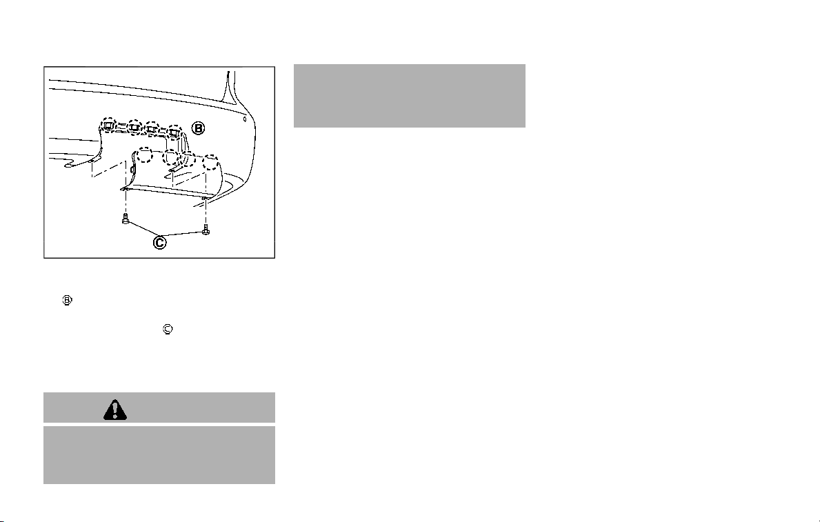
JVT0458X
To install the trailer hitch cover:
1. Insert the upper clips to the recesses
, and then push in the cover to its
original position.
2. Install the 2 bolts
.
Bolt tightening torque:
2.2 to 3.3 ft-lb (3 to 4.4 N·m)
Do not use excessive force.
WARNING
Trailer hitch components have spe-
cific weight ratings. Your vehicle may
be capable of towing a trailer heavier
than the weight rating of the hitch
components. Never exceed the
weight rating of the hitch compo-
nents. Doing so can cause serious
personal injury or property damage.
Hitch ball
Choose a hitch ball of the proper size and
weight rating for your trailer:
. The required hitch ball size is stamped
on most trailer couplers. Most hitch
balls also have the size printed on top
of the ball.
. Choose the proper class hitch ball
based on the trailer weight.
. The diameter of the threaded shank of
the hitch ball must be matched to the
ball mount hole diameter. The hitch
ball shank should be no more than
1/16″ smaller than the hole in the ball
mount.
. The threaded shank of the hitch ball
must be long enough to be properly
secured to the ball mount. There
should be at least 2 threads showing
beyond the lock washer and nut.
Ball mount
The hitch ball is attached to the ball
mount and the ball mount is inserted into
the hitch receiver. Choose a proper class
ball mount based on the trailer weight.
Additionally, the ball mount should be
chosen to keep the trailer tongue level
with the ground.
Weight carrying hitches
A weight carrying or “dead weight” ball
mount is one that is designed to carry the
whole amount of tongue weight and
gross weight directly on the ball mount
and on the receiver.
Weight distribution hitch
This type of hitch is also called a “load-
leveling” or “equalizing” hitch. A set of bars
attach to the ball mount and to the trailer
to distribute the tongue weight (hitch
weight) of your trailer. Many vehicles
cannot carry the full tongue weight of a
given trailer, and need some of the
tongue weight transferred through the
frame and pushing down on the front
wheels. This gives stability to the tow
vehicle.
A weight-distributing hitch system (Class
IV) is recommended if you plan to tow
trailers with a maximum weight over
5,000 lbs (2,267 kg). Check with the trailer
Technical and consumer information 10-23

10-24 Technical and consumer information
and towing equipment manufacturers to
determine if they recommend the use of a
weight-distributing hitch system.
NOTE:
A weight-distributing hitch system may
affect the operation of trailer surge
brakes. If you are considering use of a
weight-distributing hitch system with a
surge brake-equipped trailer, check
with the surge brake, hitch or trailer
manufacturer to determine if and how
this can be done.
Follow the instructions provided by the
manufacturer for installing and using the
weight-distributing hitch system.
General set-up instructions are as follows:
1. Park unloaded vehicle on a level sur-
face. With the ignition switch in the ON
position and the doors closed, allow
the vehicle to stand for several min-
utes so that it can level.
2. Measure the height of a reference
point on the front and rear bumpers
at the center of the vehicle.
3. Attach the trailer to the vehicle and
adjust the hitch equalizers so that the
front bumper height is within 0 - .5
inches (0 - 13 mm) of the reference
height measured in step 2. The rear
bumper should be no higher than the
reference height measured in step 2.
WARNING
Properly adjust the weight distribut-
ing hitch so the rear of the bumper is
no higher than the measured refer-
ence height when the trailer is at-
tached. If the rear bumper is higher
than the measured reference height
when loaded, the vehicle may handle
unpredictably which could cause a
loss of vehicle control and cause
serious personal injury or property
damage.
Sway control device
Sudden maneuvers, wind gusts and buf-
feting caused by other vehicles can affect
trailer handling. Sway control devices
may be used to help control these affects.
If you choose to use one, contact a
reputable trailer hitch supplier to make
sure the sway control device will work
with the vehicle, hitch, trailer and the
trailer’s brake system. Follow the instruc-
tions provided by the manufacturer for
installing and using the sway control
device.
Class I hitch
Class I trailer hitch equipment (receiver,
ball mount and hitch ball) can be used to
tow trailers of a maximum weight of
2,000 lb (907 kg).
Class II hitch
Class II trailer hitch equipment (receiver,
ball mount and hitch ball) can be used to
tow trailers of a maximum weight of
3,500 lb (1,588 kg).
Class III hitch
Class III trailer hitch equipment (receiver,
ball mount and hitch ball) can be used to
tow trailers of a maximum weight of
5,000 lb (2,267 kg).
Class IV hitch
Class IV trailer hitch equipment (receiver,
ball mount and hitch ball) can be used to
tow trailers of a maximum weight of
10,000 lb (4,545 kg). A weight distributing
hitch should be used to tow trailers that
weigh over 5,000 lb (2,267 kg).
Your vehicle may be equipped with Class
IV trailer hitch equipment that has a
10,000 lb (4,545 kg) maximum weight
rating, but your vehicle is only capable of
towing the maximum trailer weights
shown in the “Towing Load/Specification”
chart earlier in this section.
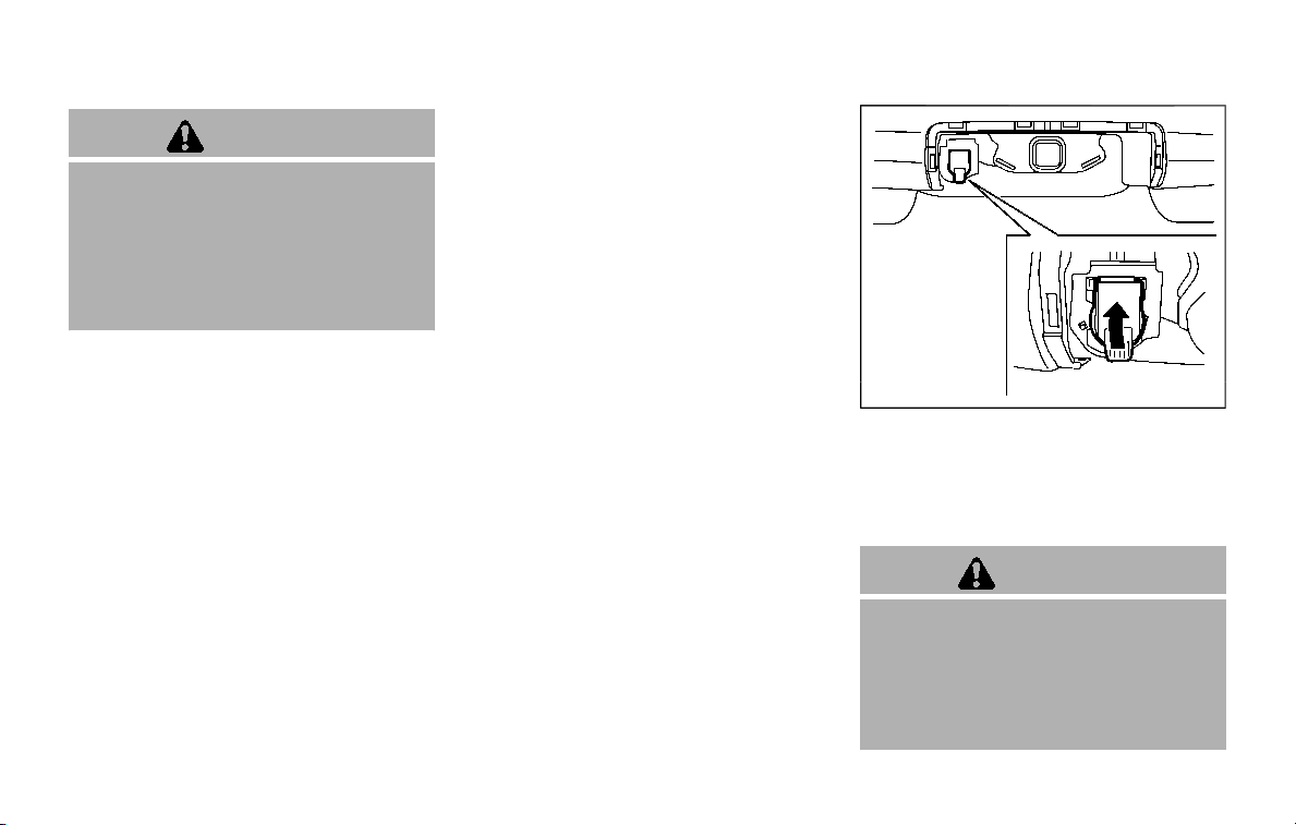
CAUTION
. Do not use axle-mounted hitches.
. Do not modify the vehicle ex-
haust system, brake system, etc.
. Do not attach any additional
hitches to your vehicle because
a hitch is already mounted to
your vehicle frame.
Tire pressures
. When towing a trailer, inflate the
vehicle tires to the recom-
mended cold tire pressure indi-
cated on the Tire and Loading
Information label.
. Trailer tire condition, size, load
rating and proper inflation pres-
sure should be in accordance
with the trailer and tire manu-
facturers’ specifications.
Safety chains
Always use a suitable chain between your
vehicle and the trailer. The safety chains
should be crossed and should be at-
tached to the hitch, not to the vehicle
bumper or axle. Be sure to leave enough
slack in the chains to permit turning
corners.
STI0745
Trailer lights (if so equipped)
Your vehicle is equipped with a towing
package, which also includes the 7-pin
trailer harness connector located under
the trailer hitch cover on the rear bumper.
CAUTION
. When splicing into the vehicle
electrical system, a commercially
available power-type module/
converter must be used to pro-
vide power for all trailer lighting.
This unit uses the vehicle battery
as a direct power source for all
Technical and consumer information 10-25

10-26 Technical and consumer information
trailer lights while using the ve-
hicle tail light, stoplight and turn
signal circuits as a signal source.
The module/converter must draw
no more than 15 milliamps from
the stop and tail lamp circuits.
Using a module/converter that
exceeds these power require-
ments may damage the vehicle’s
electrical system. See a reputable
trailer retailer to obtain the prop-
er equipment and to have it
installed.
. Do not connect electrical devices
that draw more than 40 amps to
the vehicle. The fusible link may
melt.
Trailer lights should comply with federal
and/or local regulations. For assistance in
hooking up trailer lights, contact a NISSAN
dealer or reputable trailer retailer.
Trailer brakes
When towing a trailer load of 3,500 lbs.
(1,587 kg) or more, trailers with a brake
system MUST be used. However, most
states require a separate braking system
on trailers with a loaded weight above a
specific amount. Make sure the trailer
meets the local regulations and the
regulations where you plan to tow.
Several types of braking systems are
available.
Surge Brakes - The surge brake actuator
is mounted on the trailer tongue with a
hydraulic line running to each trailer
wheel. Surge brakes are activated by the
trailer pushing against the hitch ball
when the tow vehicle is braking. Hydraulic
surge brakes are common on rental
trailers and some boat trailers. In this
type of system, there is no hydraulic or
electric connection for brake operation
between the tow vehicle and the trailer.
Electric Trailer Brakes - Electric braking
systems are activated by an electronic
signal sent from a trailer brake controller
(special brake sensing module).
Have a professional supplier of towing
equipment make sure the trailer brakes
are properly installed and demonstrate
proper brake function testing.
WARNING
Never connect a trailer brake system
directly to the vehicle brake system.
Pre-towing tips
. Be certain your vehicle maintains a
level position when a loaded or un-
loaded trailer is hitched. Do not drive
the vehicle if it has an abnormal nose-
up or nose-down condition; check for
improper tongue load, overload, worn
suspension or other possible causes
of either condition.
. Always secure items in the trailer to
prevent load shift while driving.
. Keep the cargo load as low as possible
in the trailer to keep the trailer center
of gravity low.
. Load the trailer so approximately 60%
of the trailer load is in the front half
and 40% is in the back half. Also make
sure the load is balanced side to side.
. Check your hitch, trailer tire pressure,
vehicle tire pressure, trailer light op-
eration, and trailer wheel lug nuts
every time you attach a trailer to the
vehicle.
. Be certain your rearview mirrors con-
form to all federal, state or local
regulations. If not, install any mirrors
required for towing before driving the
vehicle.
. Determine the overall height of the
vehicle and trailer so the required
clearance is known.

Trailer towing tips
In order to gain skill and an understand-
ing of the vehicle’s behavior, you should
practice turning, stopping and backing up
in an area which is free from traffic.
Steering stability, and braking perfor-
mance will be somewhat different than
under normal driving conditions.
. Always secure items in the trailer to
prevent load shift while driving.
. Lock the trailer hitch coupler with a
pin or lock to prevent the coupler from
inadvertently becoming unlatched.
. Avoid abrupt starts, acceleration or
stops.
. Avoid sharp turns or lane changes.
. Always drive your vehicle at a moder-
ate speed. Some states or provinces
have specific speed limits for vehicles
that are towing trailers. Obey the local
speed limits.
. When backing up, hold the bottom of
the steering wheel with one hand.
Move your hand in the direction in
which you want the trailer to go. Make
small corrections and back up slowly.
If possible, have someone guide you
when you are backing up.
Always block the wheels on both vehicle
and trailer when parking. Parking on a
slope is not recommended; however, if
you must do so:
CAUTION
If you move the shift lever to the P
(Park) position before blocking the
wheels and applying the parking
brake, transmission damage could
occur.
1. Apply and hold the brake pedal.
2. Have someone place blocks on the
downhill side of the vehicle and trailer
wheels.
3. After the wheel blocks are in place,
slowly release the brake pedal until
the blocks absorb the vehicle load.
4. Apply the parking brake.
5. Shift the transmission into P (Park).
6. Four-Wheel Drive (4WD) models:
Make sure that the 4WD shift switch is
engaged in the AUTO, 4HI or 4LO
position and the Automatic Transmis-
sion (AT) park warning light is turned
off.
7. Turn off the engine.
To drive away:
1. Apply and hold the brake pedal.
2. Start the engine.
3. Shift the transmission into gear.
4. Release the parking brake.
5. Drive slowly until the vehicle and
trailer are clear from the blocks.
6. Apply and hold the brake pedal.
7. Have someone retrieve and store the
blocks.
. While going downhill, the weight of the
trailer pushing on the tow vehicle may
decrease overall stability. Therefore, to
maintain adequate control, reduce
your speed and shift to a lower gear.
Avoid long or repeated use of the
brakes when descending a hill, as this
reduces their effectiveness and could
cause overheating. Shifting to a lower
gear instead provides “engine braking”
and reduces the need to brake as
frequently.
. If the engine coolant temperature
rises to a high temperature, see “If
your vehicle overheats” (P.6-14).
. Trailer towing requires more fuel than
normal circumstances.
. Avoid towing a trailer for your vehicle’s
first 500 miles (800 km).
. Have your vehicle serviced more often
than at intervals specified in the
recommended maintenance schedule
shown in the "9. Maintenance and
Technical and consumer information 10-27

10-28 Technical and consumer information
schedules" section.
. When making a turn, your trailer
wheels will be closer to the inside of
the turn than your vehicle wheels. To
compensate for this, make a larger
than normal turning radius during the
turn.
. Crosswinds and rough roads will ad-
versely affect vehicle/trailer handling,
possibly causing vehicle sway. When
being passed by larger vehicles, be
prepared for possible changes in
crosswinds that could affect vehicle
handling.
Do the following if the trailer begins to
sway:
1. Take your foot off the accelerator
pedal to allow the vehicle to coast
and steer as straight ahead as the
road conditions allow. This combina-
tion will help stabilize the vehicle.
.
Do not correct trailer sway by
steering or applying the brakes.
2. When the trailer sway stops, gently
apply the brakes and pull to the side
of the road in a safe area.
3. Try to rearrange the trailer load so it is
balanced as described earlier in this
section.
. Be careful when passing other vehi-
cles. Passing while towing a trailer
requires considerably more distance
than normal passing. Remember the
length of the trailer must also pass the
other vehicle before you can safely
change lanes.
. Use the Tow mode or downshift the
transmission to a lower gear for en-
gine braking when driving down steep
or long hills. This will help slow the
vehicle without applying the brakes.
. Avoid holding the brake pedal down
too long or too frequently. This could
cause the brakes to overheat, result-
ing in reduced braking efficiency.
. Increase your following distance to
allow for greater stopping distances
while towing a trailer. Anticipate stops
and brake gradually.
. NISSAN recommends that the cruise
control not be used while towing a
trailer.
. While towing a trailer, do not use the
following systems (if so equipped):
— the Lane Departure Warning (LDW)
system
— the Intelligent Lane Intervention (I-
LI) system
— the Blind Spot Warning (BSW) sys-
tem
— the Intelligent Blind Spot Interven-
tion (I-BSI) system
— the Intelligent Back-up Intervention
(I-BI) system
— the Intelligent Cruise Control (ICC)
system
— the Intelligent Distance Control (I-
DC) system
— the Automatic Emergency Braking
(AEB) system
— the Intelligent Forward Collision
Warning (I-FCW) system
. Some states or provinces have speci-
fic regulations and speed limits for
vehicles that are towing trailers. Obey
the local speed limits.
. Check your hitch, trailer wiring har-
ness connections, and trailer wheel
lug nuts after 50 miles (80 km) of
travel and at every break.
. When launching a boat, do not allow
the water level to go over the exhaust
tail pipe or rear bumper.
. Make sure you disconnect the trailer
lights (if so equipped) before backing
the trailer into the water or the trailer
lights may burn out.
When towing a trailer, the transmission
fluid should be changed more fre-
quently. For additional information,
see the "9. Maintenance and schedules"
section.

TOW mode
Using TOW mode is recommended when
pulling a heavy trailer or hauling a heavy
load. Push the TOW MODE switch to
activate tow mode. The TOW MODE
indicator light in the meter illuminates
when TOW mode is selected. Push the
TOW MODE switch again to turn TOW
mode off. TOW mode is automatically
cancelled when the ignition switch is
placed in the OFF position.
TOW mode includes the following fea-
tures:
. Grade logic — Adjusts transmission
shifts when pulling a trailer or hauling
a load up a grade.
. Downhill Speed Control (DSC) — auto-
matically downshifts when driving
down a grade with a trailer or heavy
load to help control vehicle speed.
Driving the vehicle in the TOW mode with
no trailer/load or light trailer/light load
will not cause any damage. However, fuel
economy may be reduced and the trans-
mission/engine driving characteristics
may feel unusual.
When towing a trailer, the transmission
fluid should be changed more fre-
quently. For additional information,
see the "9. Maintenance and schedules"
section.
FLAT TOWING
Towing your vehicle with all four wheels
on the ground is sometimes called flat
towing. This method is sometimes used
when towing a vehicle behind a recrea-
tional vehicle, such as a motor home.
CAUTION
. Failure to follow these guidelines
can result in severe transmission
damage.
. Whenever flat towing your vehi-
cle, always tow forward, never
backward.
. DO NOT tow any automatic trans-
mission vehicle with all four
wheels on the ground (flat tow-
ing). Doing so WILL DAMAGE inter-
nal transmission parts due to lack
of transmission lubrication.
. DO NOT tow a Four-Wheel Drive
(4WD) vehicle with any of the
wheels on the ground. Doing so
may cause serious and expensive
damage to the powertrain.
. For emergency towing proce-
dures refer to “Towing recom-
mended by NISSAN” (P.6-17).
Automatic Transmission
Four-Wheel Drive (4WD) models:
Do not tow a 4WD vehicle with any of the
wheels on the ground.
Two-Wheel Drive (2WD) models:
To tow a vehicle equipped with an auto-
matic transmission, an appropriate vehi-
cle dolly MUST be placed under the towed
vehicle’s drive wheels. Always follow the
dolly manufacturer’s recommendations
when using their product.
Technical and consumer information 10-29

10-30 Technical and consumer information
DOT (Department Of Transportation)
Quality Grades: All passenger car tires
must conform to federal safety require-
ments in addition to these grades.
Quality grades can be found where ap-
plicable on the tire sidewall between
tread shoulder and maximum section
width. For example:
Treadwear 200 Traction AA Tempera-
ture A
TREADWEAR
The treadwear grade is a comparative
rating based on the wear rate of the tire
when tested under controlled conditions
on a specified government test course.
For example, a tire graded 150 would
wear one and one-half (1 1/2) times as
well on the government course as a tire
graded 100. The relative performance of
tires depends upon actual conditions of
their use, however, and may depart sig-
nificantly from the norm due to variations
in driving habits, service practices and
differences in road characteristics and
climate.
TRACTION AA, A, B AND C
The traction grades, from highest to low-
est, are AA, A, B and C. Those grades
represent the tire’s ability to stop on wet
pavement as measured under controlled
conditions on specified government test
surfaces of asphalt and concrete. A tire
marked C may have poor traction perfor-
mance.
WARNING
The traction grade assigned to this
tire is based on straight-ahead brak-
ing traction tests, and does not
include acceleration, cornering, hy-
droplaning, or peak traction charac-
teristics.
TEMPERATURE A, B AND C
The temperature grades A (the highest),
B, and C, representing the tire’s resistance
to the generation of heat and its ability to
dissipate heat when tested under con-
trolled conditions on a specified indoor
laboratory test wheel. Sustained high
temperature can cause the material of
the tire to degenerate and reduce tire life,
and excessive temperature can lead to
sudden tire failure. The grade C corre-
sponds to a level of performance which
all passenger car tires must meet under
the Federal Motor Vehicle Safety Stan-
dard No. 109. Grades B and A represent
higher levels of performance on the
laboratory test wheel than the minimum
required by law.
WARNING
The temperature grade for this tire is
established for a tire that is properly
inflated and not overloaded. Exces-
sive speed, under-inflation, or exces-
sive loading, either separately or in
combination, can cause heat build-
up and possible tire failure.
UNIFORM TIRE QUALITY GRADING

Your NISSAN is covered by the following
emission warranties.
For USA:
. Emission Defects Warranty
. Emissions Performance Warranty
Details of these warranties may be found
with other vehicle warranties in your
Warranty Information Booklet that comes
with your NISSAN. If you did not receive a
Warranty Information Booklet, or it has
become lost, you may obtain a replace-
ment by writing to:
. NISSAN Division
Nissan North America, Inc.
Consumer Affairs Department
P.O. Box 685003
Franklin, TN 37068-5003
For Canada:
Emission Control System Warranty
Details of these warranties may be found
with other vehicle warranties in your
Warranty and Roadside Assistance Infor-
mation that comes with your NISSAN. If
you did not receive a Warranty and Road-
side Assistance Information, or it has
become lost, you may obtain a replace-
ment by writing to:
. Nissan Canada Inc.
5290 Orbitor Drive
Mississauga, Ontario,
L4W 4Z5
For USA
If you believe that your vehicle has
a defect which could cause a crash
or could cause injury or death, you
should immediately inform the Na-
tional Highway Traffic Safety Ad-
ministration (NHTSA) in addition to
notifying NISSAN.
If NHTSA receives similar com-
plaints, it may open an investiga-
tion, and if it finds that a safety
defect exists in a group of vehicles,
it may order a recall and remedy
campaign. However, NHTSA cannot
become involved in individual pro-
blems between you, your dealer, or
NISSAN.
To contact NHTSA, you may call the
Vehicle Safety Hotline toll-free at 1-
888-327-4236 (TTY: 1-800-424-
9153); go to http://www.safercar.
gov; or write to: Administrator,
NHTSA, 400 Seventh Street, SW.,
Washington, D.C. 20590. You can
also obtain other information
about motor vehicle safety from
http://www.safercar.gov.
Technical and consumer information 10-31
EMISSION CONTROL SYSTEM WARRANTY
REPORTING SAFETY DEFECTS

10-32 Technical and consumer information
You may notify NISSAN by contact-
ing our Consumer Affairs Depart-
ment, toll-free, at 1-800-NISSAN-1
(1-800-647-7261).
For Canada
If you believe that your vehicle has
a defect which could cause a crash
or could cause injury or death, you
should immediately inform Trans-
port Canada in addition to notifying
NISSAN.
If Transport Canada receives com-
plaints, it may open an investiga-
tion, and if it finds that a safety
defect exists in a group of vehicles,
it may request that NISSAN con-
duct a recall campaign. However,
Transport Canada cannot become
involved in individual problems be-
tween you, your dealer, or NISSAN.
You may contact Transport Cana-
da’s Defect Investigations and Re-
calls Division toll free at 1-800-333-
0510. You may also report safety
defects online at:
https://wwwapps.tc.gc.ca/Saf-Sec-Sur/
7/ PCDB-BDPP/Index.aspx.
Additional information concerning
motor vehicle safety may be ob-
tained from Transport Canada’s
Road Safety Information Centre at
1-800-333-0371 or online at www.
tc.gc.ca/roadsafety (English speak-
ers) or www.tc.gc.ca/securiterou-
tiere (French speakers).
To notify NISSAN of any safety
concerns please contact our Con-
sumer Information Centre toll free
at 1-800-387-0122.
WARNING
A vehicle equipped with Four-Wheel
Drive (4WD) should never be tested
using a two wheel dynamometer
(such as the dynamometers used by
some states for emissions testing),
or similar equipment. Make sure you
inform test facility personnel that
your vehicle is equipped with 4WD
before it is placed on a dynam-
ometer. Using the wrong test equip-
ment may result in transmission
damage or unexpected vehicle
movement which could result in
serious vehicle damage or personal
injury.
Due to legal requirements in some states
and Canadian Provinces, your vehicle may
be required to be in what is called the
“ready condition” for an Inspection/Main-
tenance (I/M) test of the emission control
system.
The vehicle is set to the “ready condition”
when it is driven through certain driving
patterns. Usually, the “ready condition”
can be obtained by ordinary usage of
the vehicle.
If a powertrain system component is
repaired or the battery is disconnected,
READINESS FOR INSPECTION/
MAINTENANCE (I/M) TEST

the vehicle may be reset to a “not ready
condition”. Before taking the I/M test,
check the vehicle’s inspection/mainte-
nance test readiness condition. Place the
ignition switch in the ON position without
starting the engine. If the Malfunction
Indicator Light (MIL) comes on steady for
20 seconds and then blinks for 10 sec-
onds, the I/M test condition is “not ready”.
If the MIL does not blink after 20 seconds,
the I/M test condition is “ready”.
It is recommended you visit a NISSAN
dealer to set “ready condition” or to
prepare the vehicle for testing.
This vehicle is equipped with an Event
Data Recorder (EDR). The main purpose of
an EDR is to record, in certain crash or
near crash-like situations, such as an air
bag deployment or hitting a road obsta-
cle, data that will assist in understanding
how a vehicle’s systems performed. The
EDR is designed to record data related to
vehicle dynamics and safety systems for a
short period of time, typically 30 seconds
or less. The EDR in this vehicle is designed
to record such data as:
. How various systems in your vehicle
were operating;
. Whether or not the driver and passen-
ger safety belts were buckled/fas-
tened;
. How far (if at all) the driver was
depressing the accelerator and/or
brake pedal; and,
. How fast the vehicle was traveling.
. Sounds are not recorded.
These data can help provide a better
understanding of the circumstances in
which crashes and injuries occur.
NOTE: EDR data are recorded by your
vehicle only if a nontrivial crash situation
occurs; no data are recorded by the EDR
under normal driving conditions and no
personal data (e.g. name, gender, age and
crash location) are recorded. However,
other parties, such as law enforcement,
could combine the EDR data with the type
of personally identifying data routinely
acquired during a crash investigation.
To read data recorded by an EDR, special
equipment is required and access to the
vehicle or the EDR is needed. In addition
to the vehicle manufacturer and NISSAN
dealer, other parties, such as law enforce-
ment, that have the special equipment,
can read the information if they have
access to the vehicle or the EDR. EDR data
will only be accessed with the consent of
the vehicle owner or lessee or as other-
wise required or permitted by law.
Technical and consumer information 10-33
EVENT DATA RECORDERS (EDR)

10-34 Technical and consumer information
Genuine NISSAN Service Manual for this
model year and prior can be purchased. A
genuine NISSAN Service Manual is the
best source of service and repair informa-
tion for your vehicle. This manual is the
same one used by the factory-trained
technicians working at NISSAN dealers.
Genuine NISSAN Owner’s Manual can also
be purchased.
For USA:
For current pricing and availability of
genuine NISSAN Service Manuals, con-
tact:
www.nissan-techinfo.com
For current pricing and availability of
genuine NISSAN Owner’s Manuals, con-
tact:
1-800-247-5321
For Canada:
To purchase a copy of a genuine NISSAN
Service Manual or Owner’s Manual for this
model year and prior, contact a NISSAN
dealer. For the phone number and loca-
tion of a NISSAN dealer in your area, call
the NISSAN Satisfaction Center at 1-800-
387-0122 and a bilingual NISSAN repre-
sentative will assist you.
OWNER’S MANUAL/SERVICE
MANUAL ORDER INFORMATION

MEMO
Technical and consumer information 10-35

10-36 Technical and consumer information
MEMO

11 Index
A
ABS (Anti-lock Braking System) .................... 5-131
Advanced Air Bag System.................................... 1-60
Air bag system
Advanced Air Bag System............................. 1-60
Front passenger air bag and
status light................................................................. 1-62
Front-seat mounted side-impact
supplemental air bag system..................... 1-68
Roof-mounted curtain side-impact
and rollover supplemental air
bag system................................................................ 1-68
Air bag warning labels ............................................ 1-70
Air bag warning light................................. 1-71, 2-17
Air cleaner housing filter....................................... 8-15
Air conditioner
Air conditioner operation............................... 4-35
Air conditioner service...................................... 4-43
Air conditioner specification label....... 10-12
Air conditioning system
refrigerant and lubricant
recommendations ................................ 4-43, 10-6
Automatic air conditioner ............................. 4-36
In-cabin microfilter.............................................. 4-43
Alarm, How to stop alarm (see vehicle
security system)............................................................ 2-31
Alcohol, drugs and driving................................... 5-10
All-mode 4WD.............................................................. 5-116
Antenna............................................................................... 4-43
Anti-lock Braking System (ABS) .................... 5-131
Anti-lock Braking System (ABS)
warning light................................................................... 2-11
Appearance care
Exterior appearance care ................................. 7-2
Interior appearance care................................... 7-5
Armrest................................................................................ 1-11
Audible reminders....................................................... 2-20
Auto closure .................................................................... 3-25
Automatic
Air conditioner ........................................................ 4-36
Automatic Transmission Fluid (ATF) ........ 8-8
Door locks...................................................................... 3-6
Drive positioner...................................................... 3-40
Driving with
automatic transmission.................................. 5-18
Seat positioner ....................................................... 3-40
Automatic Emergency Braking (AEB).......... 5-98
Automatic Emergency Braking (AEB)
system warning light................................................ 2-11
Average fuel consumption and speed....... 2-28
Avoiding collision and rollover.............................. 5-8
B
Back door (See liftgate).......................................... 3-22
Battery.................................................................................. 8-11
Battery saver system.......................... 2-39, 2-67
Intelligent Key.......................................................... 8-21
Variable voltage control system .............. 8-13
Before starting the engine................................... 5-16
Belts (See drive belts)............................................... 8-13
Blind Spot Warning (BSW)..................................... 5-32
Blind Spot Warning (BSW)/Intelligent
Blind Spot Intervention (I-BSI) system
warning light................................................................... 2-12
Booster seats.................................................................. 1-51
Brake
Anti-lock Braking System (ABS) ............ 5-131
Brake booster.......................................................... 8-17
Brake fluid ..................................................................... 8-9
Brake system ....................................................... 5-130
Parking brake operation................................. 5-22
Warning light............................................................ 2-12
Break-in schedule .................................................... 5-115
Brightness control
Instrument panel.................................................. 2-40
Bulb check/instrument panel............................ 2-11
Bulb replacement........................................................ 8-24
C
Cabin air filter................................................................. 4-43
Capacities and
recommended fluids/lubricants...................... 10-2
Car phone or CB radio............................................ 4-44
Cargo floor box............................................................. 2-60
Cargo light ........................................................................ 2-70
Catalytic converter, Three way catalyst ....... 5-4
Child restraints .............................................................. 1-32
Booster seats........................................................... 1-51
LATCH system......................................................... 1-35
Precautions on child restraints................. 1-33
Top tether strap.................................................... 1-37
Child safety....................................................................... 1-30
Child safety rear door lock ...................................... 3-6
Chimes
Audible reminders................................................ 2-20
Seat belt warning light and chime......... 2-16
Circuit breaker, Fusible link ................................. 8-19
Cleaning exterior and interior................... 7-2, 7-5
Climate control.............................................................. 4-35
Coat hooks ....................................................................... 2-59
Cockpit..................................................................................... 2-3
Cold weather driving............................................. 5-135
Console box..................................................................... 2-56
Console light ................................................................... 2-69

11-2
Coolant
Capacities and
recommended fluids/lubricants............... 10-2
Changing engine coolant ................................. 8-5
Checking engine coolant level...................... 8-5
Corrosion protection .................................................... 7-7
Cruise control
Fixed speed cruise control (on
ICC system)................................................................ 5-81
Intelligent Cruise Control (ICC) ................. 5-63
Cup holders...................................................................... 2-53
D
Daytime running light system........................... 2-39
Dimensions....................................................................... 10-9
Drive belts.......................................................................... 8-13
Drive positioner............................................................. 3-40
Driving
Cold weather driving..................................... 5-135
Driving with
automatic transmission.................................. 5-18
On-pavement and off-road driving .......... 5-9
Precautions when starting
and driving.................................................................... 5-4
Safety precautions .............................................. 5-10
E
Economy, Fuel............................................................. 5-116
Elapsed time.................................................................... 2-28
Emission control information label............ 10-11
Emission control system warranty ............ 10-31
Engine
Before starting the engine............................ 5-16
Break-in schedule ............................................ 5-115
Capacities and recommended fluids/
lubricants .................................................................... 10-2
Changing engine coolant ................................. 8-5
Changing engine oil and filter ...................... 8-6
Checking engine coolant level...................... 8-5
Checking engine oil level................................... 8-6
Coolant temperature gauge .......................... 2-7
Emergency engine shut off.......................... 5-15
Engine block heater ....................................... 5-136
Engine compartment
check locations......................................................... 8-3
Engine cooling system........................................ 8-4
Engine oil........................................................................ 8-6
Engine oil and oil
filter recommendation ..................................... 10-5
Engine oil replacement indicator ............ 2-26
Engine oil viscosity.............................................. 10-6
Engine serial number.................................... 10-11
Engine specifications......................................... 10-7
Engine start operation indicator.............. 2-23
If your vehicle overheats................................ 6-14
Oil pressure gauge................................................. 2-8
Protection mode................................................... 5-17
Remote engine start
operation indicator ............................................. 2-23
Starting the engine............................................. 5-16
Entry/exit function, Automatic
drive positioner ............................................................. 3-40
Event Data Recorders (EDR)............................. 10-33
Exhaust gas (carbon monoxide) ......................... 5-4
Explanation of scheduled
maintenance items........................................................ 9-5
Extended storage fuse warning...................... 2-24
Extended storage switch ...................................... 8-21
F
F.M.V.S.S./C.M.V.S.S. certification label ...... 10-11
Filter
Air cleaner housing filter................................ 8-15
Changing engine oil and filter ...................... 8-6
Flashers (See hazard warning
flasher switch).................................................................... 6-2
Flat tire..................................................................................... 6-3
Flat towing..................................................................... 10-29
Flexible seating.............................................................. 1-12
Floor mat cleaning......................................................... 7-5
Fluid
Automatic Transmission Fluid (ATF) ........ 8-8
Brake fluid ..................................................................... 8-9
Capacities and
recommended fluids/lubricants............... 10-2
Engine coolant........................................................... 8-4
Engine oil........................................................................ 8-6
Power steering fluid .............................................. 8-8
Window washer fluid ......................................... 8-10
Fog light switch............................................................ 2-41
Four-Wheel Drive (4WD)
NISSAN all-mode 4WD®................................ 5-116
Front passenger air bag and
status light........................................................................ 1-62
Front power seat adjustment............................... 1-4
Front seat
Front seat adjustment ......................... 1-4, 1-11
Front-seat active head restraint..................... 1-19
Fuel
Capacities and
recommended fluids/lubricants............... 10-2
Fuel economy...................................................... 5-116
Fuel information.................................................... 10-3
Fuel octane rating ............................................... 10-3
Fuel-filler cap............................................................ 3-26

Fuel-filler door......................................................... 3-26
Gauge................................................................................ 2-8
LOOSE FUEL CAP warning............................. 3-29
Fuel efficient driving tips.................................... 5-115
Fuses...................................................................................... 8-18
Fusible links...................................................................... 8-19
G
Garage door opener
HomeLink®
Universal Transceiver......................... 2-70, 2-74
Gas cap................................................................................ 3-26
Gauge........................................................................................ 2-5
Engine coolant temperature gauge......... 2-7
Engine oil pressure gauge ............................... 2-8
Fuel gauge .................................................................... 2-8
Odometer....................................................................... 2-6
Speedometer .............................................................. 2-6
Tachometer.................................................................. 2-7
Trip computer ......................................................... 2-28
General maintenance ................................................... 9-2
Glove box ........................................................................... 2-56
H
Hazard warning flasher switch ............................ 6-2
Head restraints/headrests................................... 1-14
Headlights
Bulb replacement................................................. 8-24
Headlight switch ................................................... 2-37
Heated seats ................................................................... 2-43
Heated steering wheel............................................ 2-42
Heater
Automatic air conditioner ............................. 4-36
Engine block heater ....................................... 5-136
Heater and air conditioner
operation..................................................................... 4-35
Hill start assist system ......................................... 5-124
HomeLink® Universal Transceiver..... 2-70, 2-74
Hood release ................................................................... 3-21
Hook
Coat hooks ................................................................ 2-59
Luggage hook......................................................... 2-59
Horn........................................................................................ 2-42
I
Ignition switch (Push-button)............................ 5-13
Immobilizer system.................................................... 2-31
In-cabin microfilter..................................................... 4-43
Indicator
Lights.............................................................................. 2-17
Vehicle information display.......................... 2-20
Inside mirror .................................................................... 3-31
Inspection/Maintenance (I/M) test............. 10-32
Instrument brightness control ......................... 2-40
Instrument panel............................................................. 2-4
Intelligent Around View Monitor ..................... 4-10
Intelligent Auto Headlight system ................. 2-38
Intelligent Back-up Intervention (I-BI)......... 5-53
Intelligent Blind Spot
Intervention (I-BSI) ...................................................... 5-40
Intelligent Blind Spot Intervention (I-BSI)
ON indicator light........................................................ 2-18
Intelligent Cruise Control (ICC) ........................ 5-63
Intelligent Cruise Control (ICC) system
main switch indicator....................................... 2-25
Intelligent Cruise Control (ICC) system
warning light................................................................... 2-14
Intelligent Distance Control (I-DC) ................. 5-85
Intelligent Distance Control (I-DC) system
warning light................................................................... 2-13
Intelligent Forward Collision Warning
(I-FCW)................................................................................ 5-106
Intelligent Key..................................................................... 3-2
Intelligent Key system ................................................. 3-7
Battery replacement.......................................... 8-21
Key operating range............................................. 3-9
Key operation.......................................................... 3-10
Warning light............................................................ 2-14
Warning signals...................................................... 3-12
Intelligent Key warning light .............................. 2-14
Intelligent Lane Intervention (I-LI).................. 5-23
Intelligent Lane Intervention (I-LI) ON
indicator light (green) .............................................. 2-18
Intelligent Rear View Mirror................................. 3-32
Interior light replacement..................................... 8-26
Interior light switch.................................................... 2-68
Interior lights................................................................... 2-68
ISOFIX child restraint ................................................ 1-35
J
Jump starting ................................................................. 6-12
K
Keyless entry (See remote keyless
entry system).................................................................. 3-15
Keys............................................................................................ 3-2
For Intelligent Key system................................ 3-7
L
Labels
Air bag warning labels ..................................... 1-70
Air conditioner specification label....... 10-12
Emission control information label .... 10-11
Engine serial number.................................... 10-11
11-3

11-4
F.M.V.S.S./C.M.V.S.S. certification
label............................................................................. 10-11
Tire and Loading
information label................................ 8-32, 10-12
Vehicle identification number (VIN) .... 10-10
Lane Departure Warning (LDW) indicator
light (orange)................................................................... 2-14
Lane Departure Warning (LDW)/Intelligent
Lane Intervention (I-LI)............................................ 5-23
LATCH system................................................................ 1-35
License plate, Installing front
license plate.................................................................. 10-12
Liftgate................................................................................. 3-22
Light
Air bag warning light......................................... 1-71
Bulb replacement................................................. 8-24
Cargo light ................................................................. 2-70
Fog light switch..................................................... 2-41
Headlight switch ................................................... 2-37
Headlights bulb replacement ..................... 8-24
Indicator lights........................................................ 2-17
Interior light switch............................................. 2-68
Interior lights............................................................ 2-68
Map lights................................................................... 2-69
Replacement ............................................................ 8-24
Vanity mirror lights............................................. 2-70
Warning/indicator lights and
audible reminders................................................ 2-11
Lights, Exterior and interior
light replacement........................................................ 8-26
Linking Intelligent Key (air conditioner)..... 4-43
Loading information (See vehicle
loading information) .............................................. 10-13
Lock
Automatic door locks........................................... 3-6
Door locks...................................................................... 3-4
Liftgate lock .............................................................. 3-22
Power door lock....................................................... 3-4
Locking with mechanical key................................ 3-4
Loose fuel cap warning.......................................... 3-26
Low outside temperature warning............... 2-25
Low tire pressure warning light ...................... 2-15
Low tire pressure warning system
(See Tire Pressure Monitoring System
(TPMS))...................................................................................... 5-5
Luggage hooks ............................................................. 2-59
M
Maintenance........................................................................ 9-2
Battery........................................................................... 8-11
General maintenance ........................................... 9-2
Inside the vehicle..................................................... 9-3
Maintenance indicators................................... 2-26
Maintenance log.................................................... 9-11
Maintenance precautions................................. 8-2
Maintenance requirements............................. 9-2
Maintenance schedules...................................... 9-7
Maintenance under severe
driving conditions ................................................ 9-10
Outside the vehicle ................................................ 9-2
Seat belt maintenance..................................... 1-29
Standard maintenance....................................... 9-7
Maintenance schedules.............................................. 9-7
Malfunction Indicator Light (MIL).................... 2-18
Map lights.......................................................................... 2-69
Master warning light................................................. 2-16
Mechanical key (Intelligent Key system)....... 3-3
Memory storage, Automatic
drive positioner ............................................................. 3-41
Meter
Trip computer ......................................................... 2-28
Meters and gauges........................................................ 2-5
Instrument brightness control .................. 2-40
Mirror
Inside mirror ............................................................. 3-31
Intelligent Rear View Mirror.......................... 3-32
Outside mirrors...................................................... 3-38
Vanity mirror ............................................................ 3-40
Monitor
Intelligent Around View Monitor .............. 4-10
Monitor, RearView Monitor...................................... 4-3
Moonroof............................................................................ 2-65
Moving Object Detection (MOD)...................... 4-29
N
New vehicle break-in............................................. 5-115
NISSAN all-mode 4WD®........................................ 5-116
NISSAN Vehicle Immobilizer System ............ 2-31
NissanConnect® Owner’s Manual....................... 4-2
O
Odometer............................................................................... 2-6
Off-road recovery............................................................ 5-9
Oil
Capacities and recommended
fluids/lubricants..................................................... 10-2
Changing engine oil and filter ...................... 8-6
Checking engine oil level................................... 8-6
Engine oil........................................................................ 8-6
Engine oil pressure gauge ............................... 2-8
Engine oil viscosity.............................................. 10-6
Oil filter replacement indicator ................. 2-26
Operation, operational indicators.................. 2-23
Outside air temperature........................................ 2-29
Outside mirrors............................................................. 3-38
Overheat, If your vehicle overheats.............. 6-14

Owner’s Manual/Service Manual order
information.................................................................... 10-34
P
Panic alarm....................................................................... 3-17
Parking
Brake break-in .................................................... 5-131
Parking brake operation................................. 5-22
Parking on hills................................................... 5-125
Phone
Car phone or CB radio..................................... 4-44
Pocket................................................................................... 2-58
Power
Front seat adjustment ........................................ 1-4
Moonroof..................................................................... 2-65
Power door lock....................................................... 3-4
Power outlet............................................................. 2-50
Power steering ................................................... 5-130
Power steering fluid .............................................. 8-8
Power windows ..................................................... 2-63
Precautions
Braking precautions....................................... 5-130
Child restraints ....................................................... 1-33
Driving safety........................................................... 5-10
Maintenance................................................................ 8-2
On-pavement and off-road driving .......... 5-9
Seat belt usage...................................................... 1-20
Supplemental restraint system................. 1-54
When starting and driving................................ 5-4
Push starting................................................................... 6-14
Push-button ignition switch............................... 5-13
R
Radio
Car phone or CB radio..................................... 4-44
Rain-sensing auto wiper system .................... 2-34
Rapid air pressure loss................................................ 5-9
Readiness for Inspection/Maintenance
(I/M) test........................................................................... 10-32
Rear bumper cover.................................................... 2-61
Rear door alert .............................................................. 2-48
Rear door lock, Child safety rear
door lock ................................................................................ 3-6
Rear personal lights .................................................. 2-69
Rear window wiper and washer switch .... 2-36
Rear window wiper blades .................................. 8-17
RearView Monitor............................................................ 4-3
RearView Monitor system operation............... 4-4
Recorders, Event data .......................................... 10-33
Registering your vehicle in
another country ........................................................ 10-10
Remote engine start................................................. 3-19
Remote keyless entry system........................... 3-15
Reporting safety defects.................................... 10-31
Roadside assistance program .............................. 6-2
Rollover.................................................................................... 5-8
Roof
Moonroof..................................................................... 2-66
Roof rack..................................................................... 2-60
S
Safety
Child seat belts....................................................... 1-30
Towing safety...................................................... 10-22
Seat adjustment
Front power seat adjustment....................... 1-4
Front seats..................................................... 1-4, 1-11
Seat belt(s)
Child safety................................................................ 1-30
Infants............................................................................ 1-31
Injured persons ...................................................... 1-22
Larger children ....................................................... 1-31
Precautions on seat belt usage................ 1-20
Pregnant women.................................................. 1-22
Seat belt cleaning ................................................... 7-7
Seat belt extenders............................................. 1-29
Seat belt maintenance..................................... 1-29
Seat belt warning light and chime......... 2-16
Seat belts .................................................................... 1-20
Seat belts with pretensioners.................... 1-69
Small children.......................................................... 1-31
Three-point type................................................... 1-22
Seat(s)
Climate controlled seats................................. 2-45
Driver-side memory............................................ 3-40
Heated seats ............................................................ 2-43
Seats.................................................................................. 1-3
Security system (NISSAN Vehicle
Immobilizer System), Engine start................. 2-31
Security system, Vehicle
security system............................................................. 2-30
Servicing air conditioner........................................ 4-43
Setting memory function, Automatic
drive positioner ............................................................. 3-42
Shift lever, Shift lock release............................... 5-22
Shift lock release
Transmission............................................................ 5-22
Shifting, Automatic transmission ................... 5-18
SNOW mode.................................................................. 5-127
SNOW mode switch................................................... 2-46
Sonar system............................................................... 5-127
Spare tire............................................................. 8-40, 10-8
Spark plugs....................................................................... 8-14
Speedometer ...................................................................... 2-6
Standard maintenance................................... 9-7, 9-8
Starting
Before starting the engine............................ 5-16
Jump starting .......................................................... 6-12
11-5

11-6
Precautions when starting
and driving.................................................................... 5-4
Push starting............................................................ 6-14
Starting the engine............................................. 5-16
Status light, Front passenger air bag......... 1-62
Steering
Heated steering wheel..................................... 2-42
Power steering ................................................... 5-130
Power steering fluid .............................................. 8-8
Tilt/telescopic steering .................................... 3-29
Storage ................................................................................ 2-53
Sun visors .......................................................................... 3-30
Sunglasses holder....................................................... 2-55
Supplemental air bag warning labels......... 1-70
Supplemental air bag
warning light.................................................... 1-71, 2-17
Supplemental restraint system........................ 1-54
Precautions on supplemental
restraint system .................................................... 1-54
Switch
Fog light switch..................................................... 2-41
Hazard warning flasher switch .................... 6-2
Headlight switch ................................................... 2-37
Ignition switch ........................................................ 5-18
Intelligent Auto Headlight switch............ 2-38
Power door lock switch ..................................... 3-5
SNOW mode switch............................................ 2-46
Turn signal switch ............................................... 2-41
Vehicle Dynamic Control (VDC)
OFF switch ................................................................. 2-47
T
Tachometer.......................................................................... 2-7
Temperature gauge, Engine coolant
temperature gauge ....................................................... 2-7
Theft (NISSAN Vehicle Immobilizer
System), Engine start ............................................... 2-31
Three-way catalyst......................................................... 5-4
Tilt/telescopic steering ........................................... 3-29
Tire
Pressure, Low tire pressure
warning light............................................................ 2-15
Tire replacement indicator........................... 2-26
Tires
Flat tire............................................................................. 6-3
Tire and Loading
information label................................ 8-32, 10-12
Tire chains.................................................................. 8-37
Tire dressing................................................................ 7-4
Tire pressure ............................................................ 8-30
Tire Pressure Monitoring
System (TPMS) ................................................ 5-5, 6-3
Tire rotation.............................................................. 8-37
Types of tires ........................................................... 8-36
Uniform tire quality grading .................... 10-30
Wheel/tire size ........................................................ 10-8
Wheels and tires.................................................... 8-30
Top
Tether strap child restraints........................ 1-37
TOW mode ..................................................................... 5-126
TOW mode switch....................................................... 2-47
Towing
Flat towing............................................................. 10-29
Tow truck towing................................................. 6-16
Towing a trailer.................................................. 10-17
Towing safety...................................................... 10-22
TPMS, Tire Pressure
Monitoring System............................................. 5-5, 6-3
TPMS with Easy Fill Tire Alert......................... 5-8
Trailer towing .............................................................. 10-17
Transceiver
HomeLink® Universal
Transceiver................................................. 2-70, 2-74
Transmission
Automatic Transmission Fluid (ATF) ........ 8-8
Driving with
automatic transmission.................................. 5-18
Transmission shift lever lock release..... 5-22
Transmitter (See remote keyless
entry system).................................................................. 3-15
Traveling or registering your vehicle in
another country ........................................................ 10-10
Trip computer ................................................................ 2-28
Trip odometer................................................................ 2-28
Turn signal switch ...................................................... 2-41
U
Underbody cleaning...................................................... 7-3
Uniform tire quality grading ............................ 10-30
USB (Universal Serial Bus)
charging connector................................................... 2-52
V
Vanity mirror ................................................................... 3-40
Vanity mirror lights.................................................... 2-70
Variable voltage control system ..................... 8-13
Vehicle
Dimensions................................................................ 10-9
Identification number (VIN)....................... 10-10
Loading information ...................................... 10-13
Recovery (freeing a stuck vehicle).......... 6-19
Security system...................................................... 2-30
Vehicle Dynamic Control (VDC)
OFF switch ................................................................. 2-47

Vehicle Dynamic Control (VDC)
system....................................................................... 5-133
Vehicle Dynamic Control (VDC)
warning light............................................................ 2-17
Vehicle information display................................. 2-20
Ventilators......................................................................... 4-34
Voltmeter............................................................................... 2-9
W
Warning
Check tire pressure warning....................... 2-24
Hazard warning flasher switch .................... 6-2
Intelligent Forward Collision
Warning (I-FCW).................................................. 5-106
Lights.............................................................................. 2-11
Loose fuel cap warning................................... 2-24
Tire Pressure Monitoring
System (TPMS) ................................................ 5-5, 6-3
Vehicle information display.......................... 2-20
Warning lights, indicator lights and
audible reminders................................................ 2-10
Warning labels, Air bag warning labels...... 1-70
Warning light
4WD warning light........................................... 5-122
Air bag warning light.......................... 1-71, 2-17
Anti-lock Braking System (ABS)
warning light............................................................ 2-11
Automatic Emergency Braking (AEB)
system warning light......................................... 2-11
Brake warning light ............................................ 2-12
Intelligent Key warning light ....................... 2-14
Lane Departure Warning (LDW)
indicator light (orange).................................... 2-14
Low tire pressure warning light ............... 2-15
Seat belt warning light and chime......... 2-16
Warranty, Emission control system
warranty .......................................................................... 10-31
Washer switch
Rear window wiper and washer
switch............................................................................. 2-36
Windshield wiper and washer
switch............................................................................. 2-33
Washing................................................................................... 7-2
Waxing...................................................................................... 7-2
Welcome light................................................................. 2-67
Wheel/tire size ............................................................... 10-8
Wheels and tires........................................................... 8-30
Care of wheels........................................................... 7-3
Cleaning aluminum alloy wheels................ 7-3
Cleaning bright wheels....................................... 7-4
Window washer fluid ................................................ 8-10
Window(s)
Cleaning.......................................................................... 7-3
Power windows ..................................................... 2-63
Windshield wiper and washer switch.......... 2-33
Wiper
Rain-sensing auto wiper system ............. 2-34
Rear window wiper and
washer switch......................................................... 2-36
Windshield wiper and
washer switch......................................................... 2-33
Wiper blades ............................................................. 8-16
11-7

FUEL INFORMATION
VK56VD engine
Use unleaded regular gasoline with an
octane rating of at least 87 AKI (Anti-
Knock Index) number (Research octane
number 91).
CAUTION
. Using a fuel other than that spe-
cified could adversely affect the
emission control systems, and
may also affect warranty cover-
age.
. Under no circumstances should a
leaded gasoline be used, because
this will damage the three way
catalyst.
. Do not use E-15 or E-85 fuel in
your vehicle. Your vehicle is not
designed to run on E-15 or E-85
fuel. Using E-15 or E-85 fuel in a
vehicle not specifically designed
for E-15 or E-85 fuel can adversely
affect the emission control de-
vices and systems of the vehicle.
Damage caused by such fuel is
not covered by the NISSAN new
vehicle limited warranty.
. Do not use fuel that contains the
octane booster methylcyclopen-
tadienyl manganese tricarbonyl
(MMT). Using fuel containing
MMT may adversely affect vehicle
performance and vehicle emis-
sions. Not all fuel dispensers are
labeled to indicate MMT content,
so you may have to consult your
gasoline retailer for more details.
Note that Federal and California
laws prohibit the use of MMT in
reformulated gasoline.
. U.S. government regulations re-
quire ethanol dispensing pumps
to be identified by a small,
square, orange and black label
with the common abbreviation or
the appropriate percentage for
that region.
ENGINE OIL RECOMMENDATION:
See “Capacities and recommended fluids/
lubricants” (P.10-2) for engine oil and oil
filter recommendation.
COLD TIRE PRESSURES:
The label is typically located on the driver
side center pillar or on the driver’s door.
For additional information, see “Wheels
and tires” (P.8-30).
NEW VEHICLE BREAK-IN PROCE-
DURES RECOMMENDATION:
During the first 1,200 miles (2,000 km) of
vehicle use, follow the recommendations
outlined in the “Break-in schedule” (P.5-
115). Follow these recommendations for
the future reliability and economy of your
new vehicle.
GAS STATION INFORMATION


Y62-D
Printing : July 2019
Publication No.:
Printed in the U.S.A.
OM20E0 0Y62U0