
Operation Manual
Embroidery Machine
Product Code: 884-T15
Be sure to read this document before using the machine.
We recommend that you keep this document nearby for future reference.

1
Thank you for purchasing this machine. Before using this
machine, carefully read the “IMPORTANT SAFETY
INSTRUCTIONS”, and then study this manual for the
correct operation of the various functions.
In addition, after you have finished reading this manual,
store it where it can quickly be accessed for future
reference.
Failure to follow these instructions may result in an
increased risk of personal injury or damage to property,
including through fire, electrical shock, burns or
suffocation.
Please read these safety instructions before attempting to
use the machine.
DANGER
- To reduce the risk of electric shock
1Always unplug the machine from the
electrical outlet immediately after using,
when cleaning, when making any user
servicing adjustments mentioned in this
manual, or if you are leaving the
machine unattended.
WARNING
- To reduce the risk of burns, fire, electric shock, or
injury to persons.
2Always unplug the machine from the electrical
outlet when lubricating it or when making any other
user servicing adjustments mentioned in the
Operation Manual.
• To unplug the machine, switch the machine to the
symbol “O” position to turn it off, then grasp the
plug and pull it out of the electrical outlet. Do not
pull on the cord.
• Plug the machine directly into the electrical outlet.
Do not use an extension cord.
• Always unplug your machine if the power is cut.
3Electrical Hazards:
• This machine should be connected to an AC power
source within the range indicated on the rating
label. Do not connect it to a DC power source or
inverter. If you are not sure what kind of power
source you have, contact a qualified electrician.
• This machine is approved for use in the country of
purchase only.
4Never operate this machine if it has a damaged cord
or plug, if it is not working properly, if it has been
dropped or damaged, or water is spilled on the unit.
Return the machine to the nearest authorized
Brother dealer or service center for examination,
repair, electrical or mechanical adjustment.
• To avoid electric shock or fire; do not use a
damaged power supply plug or loose electrical
outlet, and ensure that the power supply plug is fully
inserted and secure.
• While the machine is stored or in use if you notice
anything unusual, such as an odor, heat,
discoloration or deformation, stop using the
machine immediately and unplug the power cord.
• When transporting the machine, be sure to lift it
from the bottom positions. Lifting the machine by
any other part may damage the machine or result in
the machine falling, which could cause injuries.
• When lifting the machine, be careful not to make
any sudden or careless movements, otherwise you
may injure your back or knees.
• While the machine is being transported, be careful
not to touch the operation panel, thread guides or
any other part, otherwise injuries may result.
5Always keep your work area clear:
• Never operate the machine with any air openings
blocked. Keep ventilation openings of the machine
free from the build up of lint, dust, and loose cloth.
• Do not use extension cords. Plug the machine
directly into the electrical outlet.
• Never drop or insert any object into any opening.
• Keep fingers out of all machine openings, such as
near the carriage, otherwise injuries may result.
• Do not operate where aerosol (spray) products are
being used or where oxygen is being administered.
• Do not use the machine near a heat source, such as
a stove or iron; otherwise, the machine, power cord
or garment being embroidered may ignite, resulting
in fire or an electric shock.
• Do not use this machine near an open flame; the
movement of the embroidery frame could cause the
garment being embroidered to catch fire.
INTRODUCTION
IMPORTANT SAFETY
INSTRUCTIONS

2
• Do not place this machine on an unstable surface,
such as an unsteady or slanted table, otherwise the
machine may fall, resulting in injuries.
• While attaching or detaching an embroidery frame
or other included accessory or while maintaining
the machine, be careful not to hit the machine with
your body or any other part of it.
6Special care is required when embroidering:
• Always pay close attention to the needle. Do not use
bent or damaged needles.
• Keep fingers away from all moving parts. Special
care is required around the machine needle.
• While the machine is in operation, keep your hands
away from the needle bar case and all moving parts
near the needle bar case, otherwise injuries may
result.
• Switch the machine to the symbol “O” position to
turn it off when making any adjustments in the
needle area, such as changing the needle.
• Do not use a damaged or incorrect needle plate, as
it could cause the needle to break.
7This machine is not a toy:
• Your close attention is necessary when the machine
is used by or near children.
• This machine is not intended for use by young
children or infirm persons without supervision.
• Young children should be supervised to ensure that
they do not play with this machine.
• Do not use the included scissors or seam ripper in
any other way than how they are intended. In
addition, when opening a hole with the seam ripper,
do not place your hands or fingers in the cutting
path, otherwise injuries may result if the seam ripper
slips.
• The plastic bag that this machine was supplied in
should be kept out of the reach of children or
disposed of. Never allow children to play with the
bag due to the danger of suffocation.
• Do not use outdoors.
8For a longer service life:
• When storing this machine, avoid direct sunlight
and high humidity locations. Do not use or store the
machine near a space heater, iron, halogen lamp, or
other hot objects.
• Use only neutral soaps or detergents to clean the
case. Benzene, thinner, and scouring powders can
damage the case and machine, and should never be
used.
• Always consult the Operation Manual when
replacing or installing any assemblies, the presser
feet, needle, or other parts to assure correct
installation.
9For repair or adjustment:
• Do not try to disassemble, repair or alter this
machine in any way, otherwise a fire, electric shock
or injuries may result.
• If the light unit is damaged, it must be replaced by
an authorized Brother dealer.
• In the event a malfunction occurs or adjustment is
required, first follow the troubleshooting table in the
back of the Operation Manual to inspect and adjust
the machine yourself. If the problem persists, please
consult your local authorized Brother dealer.
Use this machine only for its intended use as described
in the manual.
Use accessories recommended by the manufacturer as
contained in this manual.
Use the interface cable (USB cable) included with this
machine.
The contents of this manual and specifications of this
product are subject to change without notice.
For additional product information and updates, visit
our website at www.brother.com

3
SAVE THESE
INSTRUCTIONS
This machine is intended
for household use.
FOR USERS IN COUNTRIES EXCEPT
CENELEC COUNTRIES
This appliance is not intended for use
by persons (including children) with
reduced physical, sensory or mental
capabilities, or lack of experience and
knowledge, unless they have been
given supervision or instruction
concerning use of the appliance by a
person responsible for their safety.
Children should be supervised to
ensure that they do not play with the
appliance.
FOR USERS IN CENELEC COUNTRIES
This appliance can be used by children
aged from 8 years and above and
persons with reduced physical, sensory
or mental capabilities or lack of
experience and knowledge if they have
been given supervision or instruction
concerning use of the appliance in a
safe way and understand the hazards
involved. Children shall not play with
the appliance. Cleaning and user
maintenance shall not be made by
children without supervision.
FOR USERS IN THE UK,
EIRE, MALTA AND
CYPRUS ONLY
IMPORTANT
• In the event of replacing the plug fuse, use a fuse
approved by ASTA to BS 1362, i.e. carrying the
mark, rating as marked on plug.
• Always replace the fuse cover. Never use plugs with
the fuse cover omitted.
• If the available electrical outlet is not suitable for the
plug supplied with this equipment, you should
contact your authorized Brother dealer to obtain the
correct lead.
Federal Communications
Commission (FCC)
Supplier’s Declaration of
Conformity (For U.S.A.
Only)
This device complies with Part 15 of the FCC Rules.
Operation is subject to the following two conditions: (1)
this device may not cause harmful interference, and (2)
this device must accept any interference received,
including interference that may cause undesired
operation.
This equipment has been tested and found to comply
with the limits for a Class B digital device, pursuant to
Part 15 of the FCC Rules. These limits are designed to
provide reasonable protection against harmful
interference in a residential installation. This equipment
generates, uses, and can radiate radio frequency energy
and, if not installed and used in accordance with the
instructions, may cause harmful interference to radio
communications. However, there is no guarantee that
interference will not occur in a particular installation. If
this equipment does cause harmful interference to radio
or television reception, which can be determined by
turning the equipment off and on, the user is
encouraged to try to correct the interference by one or
more of the following measures:
• Reorient or relocate the receiving antenna.
• Increase the separation between the equipment and
receiver.
• Connect the equipment into an outlet on a circuit
different from that to which the receiver is
connected.
• Consult the authorized Brother dealer or an
experienced radio/TV technician for help.
Responsible Party: Brother International Corporation
200 Crossing Boulevard
P.O. Box 6911
Bridgewater, NJ 08807-0911
USA
TEL : (908) 704-1700
declares that the product
Product Name:
Model Number:
Brother Embroidery Machine
PR1055X

4
• This transmitter must not be co-located or operated
in conjunction with any other antenna or
transmitter.
Important
Changes or modifications not expressly approved by
Brother Industries, Ltd. could void the user’s authority
to operate the equipment.
This equipment complies with FCC/IC radiation
exposure limits set forth for an uncontrolled
environment and meets the FCC radio frequency (RF)
Exposure Guidelines and RSS-102 of the IC radio
frequency (RF) Exposure rules. This equipment should
be installed and operated keeping the radiator at least
20cm or more away from person’s body.
For Users in Canada
This device complies with Industry Canada’s licence-exempt
RSSs. Operation is subject to the following two conditions:
(1) This device may not cause interference; and
(2) This device must accept any interference, including
interference that may cause undesired operation of the
device.
This equipment complies with FCC/IC radiation exposure
limits set forth for an uncontrolled environment and meets the
FCC radio frequency (RF) Exposure Guidelines and RSS-102
of the IC radio frequency (RF) Exposure rules. This equipment
should be installed and operated keeping the radiator at least
20cm or more away from person’s body.
For Users in Mexico
The operation of this equipment is subject to the following
two conditions:
(1) it is possible that this equipment or device may not cause
harmful interference, and
(2) this equipment or device must accept any interference,
including interference that may cause undesired
operation.
Declaration of Conformity
(Europe and Turkey only)
We, Brother Industries, Ltd. 15-1 Naeshiro-cho, Mizuho-ku,
Nagoya 467-8561 Japan declare that this product is in
conformity with the essential requirements of all relevant
directives and regulations applied within the European
Community.
The Declaration of Conformity (DoC) can be downloaded
from Brother support website.
Visit support.brother.com
and:
click “Manuals”
select your model
click “Declaration of Conformity”
click “Download”
Your Declaration will be downloaded as a PDF file.
Declaration of Conformity
for RE Directive 2014/53/
EU (Europe and Turkey
only)
(Applicable to models with
radio interfaces)
We, Brother Industries, Ltd. 15-1 Naeshiro-cho, Mizuho-ku,
Nagoya 467-8561 Japan declare that these products are in
conformity with the provisions of the RE Directive 2014/53/
EU. A copy of the Declaration of Conformity can be
downloaded by following the instructions in the Declaration
of Conformity (Europe and Turkey only) section.
Wireless LAN (Models with
Wireless LAN function
only)
This machine supports wireless interface.
Frequency band(s): 2400-2483.5 MHz
Maximum radio-frequency power transmitted in the
frequency band(s): Less than 20 dBm(e.i.r.p)
For Users in Norway
This subsection does not apply for the geographical area
within a radius of 20 km from the centre of Ny-Alesund on
Svalbard.
Dette underavsnittet gjelder ikke for det geografiske området
innenfor en radius av 20 km fra sentrum av Ny-Ålesund på
Svalbard.
For Users in Thailand
This telecommunication equipment conforms to NTC
technical requirement.

5
Terms of Use
IMPORTANT-PLEASE READ
CAREFULLY:
This Terms of Use (“Agreement”) is a legal agreement
between Brother Industries, Ltd. (“Company”) and you that
governs your use of any Software, installed on or made
available by Company for use with sewing or craft products
(“Company Product”). The term of “Software” means any and
all contents data, design data, data format, firmware of
Company Product, and PC application or mobile device
application.
By using the Software and Company Product, you shall be
deemed to have agreed to be bound by the terms of this
Agreement. If you do not agree to the terms of this Agreement,
Company is unwilling to license the Software and you are not
allowed to use the Software. Amendments and supplements to
this Agreement may be attached to the Software.
An individual who accepts this Agreement on behalf of an
entity represents to Company that he or she has the legal right
to enter into a binding legal agreement for that entity.
Terms and Conditions
1 Grant of License.
1.1 Subject to this Agreement, Company hereby
grants you a personal, non-exclusive, non-
transferable and revocable license to use the
Software only within the Company Product.
1.2 Your right to use of the Software is licensed and
not sold, and solely for your use subject to this
Agreement. Company or its suppliers retains all
right, title, and interest relating to Software,
including without limitation all intellectual
property rights relating thereto.
2 Restrictions
2.1 Except as expressly set out in this Agreement or
as required by any local law, you shall
undertake:
2.1.1 not to disassemble, de-compile, reverse
engineer, translate or otherwise attempt
to learn the source code of the Software
(including the data or contents created
by using the Company Product or
contents editing application software;
hereinafter the same shall apply in this
Clause 2.);
2.1.2 not to create derivative works based on
the whole or any part of the Software;
2.1.3 not to distribute, provide or make
available the Software in any form, in
whole or in part to any person without
prior written consent from Company;
2.1.4 not to copy the Software, except where
such copying is incidental to normal
use of the Software with Company
Product or where it is necessary for the
purpose of back-up or operational
security;
2.1.5 not to transfer, rent, lease, sub-license,
loan, translate, merge, adapt, vary, alter
or modify, the whole or any part of the
Software nor permit the Software or any
part of it to be combined with, or
become incorporated in, any other
programs;
2.1.6 to include Company’s copyright notice
and this Agreement on all entire and
partial copies of the Software; and
2.1.7 not to use the Software for any purpose
(including, but not limited to, use with
unauthorized sewing/craft products or
software) other than as provided under
Clause 1 of this Agreement.
3No warranty
TO THE EXTENT PERMISSIBLE BY
APPLICABLE LAW, THIS SOFTWARE IS
PROVIDED TO YOU “AS IS” WITHOUT
WARRANTIES OR CONDITIONS OF ANY
KIND, WHETHER ORAL OR WRITTEN,
EXPRESS OR IMPLIED. COMPANY
SPECIFICALLY DISCLAIMS ANY IMPLIED
WARRANTIES OR CONDITIONS OF
MERCHANTABILITY, SATISFACTORY
QUALITY, NON-INFRINGEMENT AND/OR
FITNESS FOR A PARTICULAR PURPOSE.
4 Limitation of liability
4.1 COMPANY SHALL NOT BE LIABLE TO YOU,
ITS END-USERS OR ANY OTHER ENTITY FOR
ANY LOSS OF PROFITS OR INCOME OR
SAVINGS, LOSS OF DATA, INTERRUPTION
OF USE, OR CONSEQUENTIAL,
INCIDENTAL, SPECIAL, PUNITIVE OR
INDIRECT DAMAGES INCURRED BY SUCH
PARTY (WHETHER IN AN ACTION IN
CONTRACT OR TORT), EVEN IF COMPANY
HAS BEEN ADVISED OF THE POSSIBILITY OF
SUCH DAMAGES, ARISING OUT OF OR
RELATING TO THE SOFTWARE, SUPPORT
SERVICE OR THIS AGREEMENT. THESE
LIMITATIONS SHALL APPLY TO THE
MAXIMUM EXTENT ALLOWED BY
APPLICABLE LAW NOTWITHSTANDING
ANY FAILURE OF ESSENTIAL PURPOSE OF
ANY LIMITED REMEDY.
4.2 NOTWITHSTANDING THE CLAUSE 3 OR 4.1
HEREOF, THIS AGREEMENT DOES NOT
PURPORT TO EXCLUDE OR RESTRICT
COMPANY’S LIABILITY FOR DEATH OR
PERSONAL INJURY RESULTING FROM
NEGLIGENCE OR LIMIT THE STATUTORY
RIGHTS OF A CONSUMER.

6
5Termination
5.1 Company shall have the right to terminate this
Agreement at any time by providing a written
notice to you if you commit a material breach
of any terms of this Agreement and fail to
immediately rectify such breach upon
Company’s request.
5.2 Upon termination for any reason all rights
granted to you under this Agreement shall
cease, you shall cease all activities authorized
by this Agreement and you shall immediately
delete or remove the Software from all
computer equipment in your possession and
delete or destroy all copies of the Software or
its derivative works in your possession. In
addition to the above, you shall delete contents
or design data created by you from the
Company Product in your possession.
6 Miscellaneous terms
6.1 You shall not export or re-export the Software
or any copy or adaptation thereof in violation
of any applicable laws or regulations.
6.2 You shall not assign all or any part of this
Agreement to any third party or any interest
therein, without prior written consent of
Company. A change of control or
reorganization of you pursuant to a merger,
sale of assets or stock shall be deemed to be an
assignment under this Agreement.
6.3 You agree that a breach of this Agreement will
cause irreparable injury to Company for which
monetary damages would not be an adequate
remedy and Company shall be entitled to seek
equitable relief in addition to any remedies it
may have hereunder or at law without a bond,
other security, or proof of damages.
6.4 If any provisions of this Agreement shall be
declared or determined as void or
unenforceable by a court of competent
jurisdiction, such provisions shall be severable
and independent from the other provisions of
this Agreement and the validity of the other
provisions and of the entire Agreement shall
not be affected thereby.
6.5 This Agreement, together with all exhibits or
other attachments referenced herein,
constitutes the entire agreement between the
parties on the subject matter hereof, and
supersedes all proposals, oral and written,
between the parties on this subject.
6.6 If Company fails to insist that you perform any
of your obligations under this Agreement, or if
Company does not enforce any rights against
you, or if Company delay in doing so, that will
not mean that Company have waived any
rights against you and will not mean that you
do not have to comply with those obligations.
If Company does waive a default by you,
Company will only do so in writing, and that
will not mean that Company will automatically
waive any later default by you.
6.7 The laws of the state or country where you live
(or, if a business, where your principal place of
business is located) govern all claims and
disputes concerning the Software or this
Agreement.
7
The enclosed machine includes data, software and/or
documentation (collectively “CONTENT”) that are
proprietary products of Brother Industries, Ltd.
(“BROTHER”). BY USING THE CONTENT, THE
CUSTOMER ACCEPTS THE TERMS AND CONDITIONS
OF THIS AGREEMENT. BROTHER retains ownership of all
rights to CONTENT and to the copies of the CONTENT
included in this package. The CONTENT are licensed (not
sold) to you (“CUSTOMER”) under the terms and
conditions of this Agreement.
CUSTOMER is licensed to:
• Use the CONTENT in combination with an
embroidery machine to create embroidery.
• Use the CONTENT in combination with an
embroidery machine that CUSTOMER owns or uses,
provided that the CONTENT is not used on more
than one embroidery machine at a time.
Except as otherwise provided herein, CUSTOMER may
not:
• Allow more than one copy of the CONTENT to be
available for use at any one time.
• Reproduce, modify, publish, distribute, sell, rent,
sublicense or otherwise make available to others
CONTENT.
• Distribute, rent, sublicense, lease, sell, transfer or
assign the media card or CONTENT.
• Decompile, disassemble or otherwise reverse
engineer the CONTENT or assist others to do the
same.
• Alter, translate, modify or adapt the CONTENT or
any part thereof for business, commercial or
industrial purposes.
• Sell or otherwise distribute the EMBROIDERY
created by use of the CONTENT, WHICH
ORIGINALLY BEARS CERTAIN COPYRIGHT
NOTICE UNDER THE NAME OF ANY THIRD
PARTIES OTHER THAN BROTHER (e.g.
“©DISNEY”).
BROTHER retains all rights not expressly granted to
CUSTOMER herein.
Nothing in this agreement constitutes a waiver of the rights
of BROTHER under any law. This agreement shall be
governed by the laws of Japan.
Please direct all inquiries concerning this Agreement in
writing by regular mail, to Brother Industries, Ltd., 1-1-1
Kawagishi, Mizuho-ku, Nagoya 467-8562, Japan,
Attention: P&H business division Sales and Marketing
Dept.
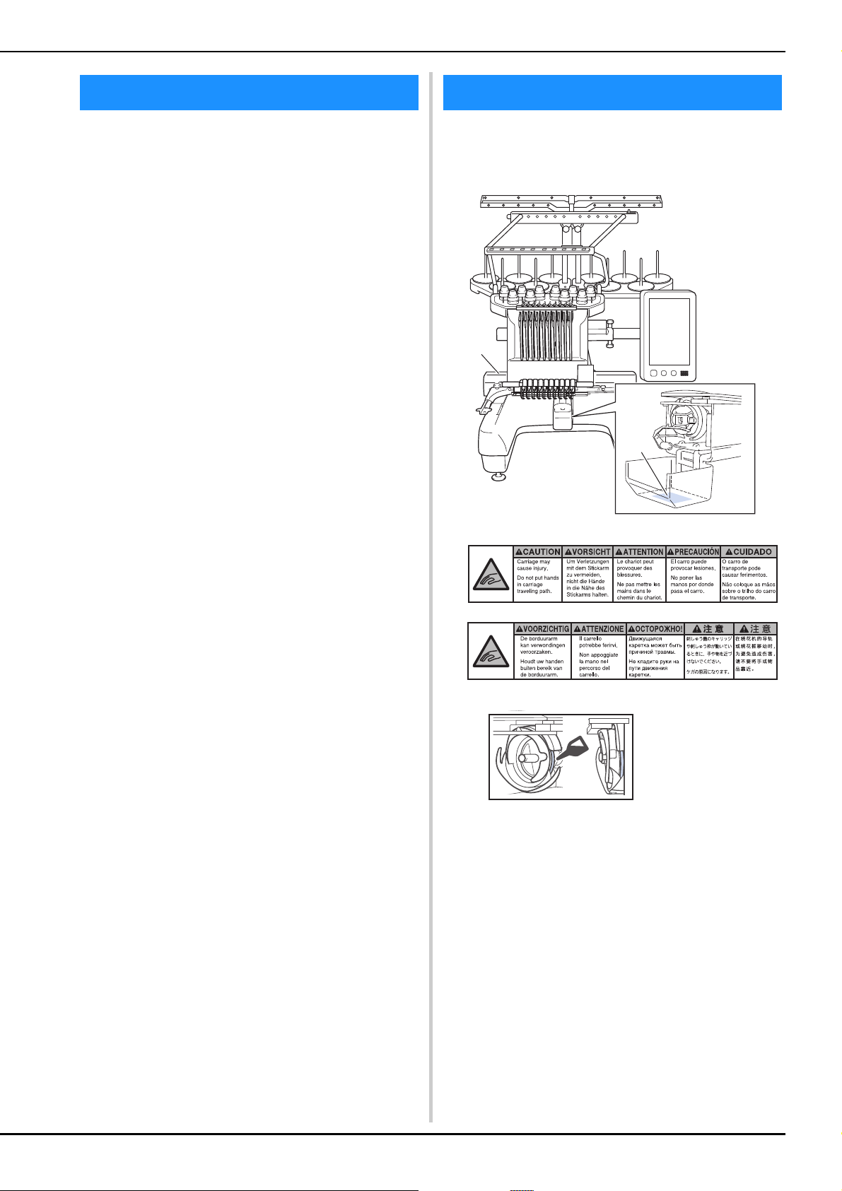
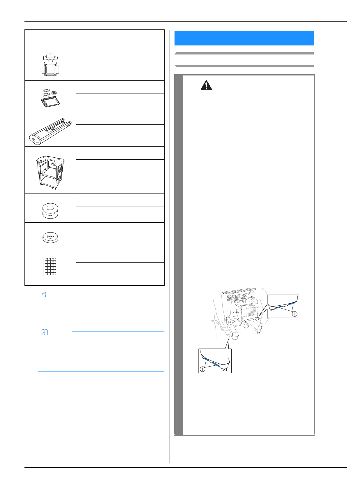
The following warning labels are on the machine.
Be sure to observe the precautions described in the labels.
LICENSE AGREEMENT WARNING LABELS
Label locations
1
2
Please put a drop of oil onto the hook
once a day before use.
a
b

8
IBM is a registered trademark or a trademark of
International Business Machines Corporation.
WPA™ and WPA2™ are trademarks of Wi-Fi Alliance®.
Secure Digital (SD) Card is a registered trademark or a
trademark of SD-3C, LLC.
CompactFlash is a registered trademark or a trademark of
Sandisk Corporation.
Memory Stick is a registered trademark or a trademark of
Sony Corporation.
SmartMedia is a registered trademark or a trademark of
Toshiba Corporation.
MultiMediaCard (MMC) is a registered trademark or a
trademark of Infineon Technologies AG.
xD-Picture Card is a registered trademark or a trademark of
Fuji Photo Film Co. Ltd.
This software is based in part on the work of the
Independent JPEG Group.
Android and Google Play are trademarks of Google LLC.
App Store is a service mark of Apple Inc.
Each company whose software title is mentioned in this manual has a
Software License Agreement specific to its proprietary programs.
Any trade names and product names of companies appearing on
Brother products, related documents and any other materials are all
trademarks or registered trademarks of those respective companies.
This product includes open-source software.
To see the open source licensing remarks, please go to the
manual download section on your model’s home page of
Brother support website at “ http://s.brother/cpbag/
”.
Make sure you use a router or firewall when connecting
your machine to the Internet to protect it against
unauthorized access from the Internet.
TRADEMARKS OPEN SOURCE LICENSING
REMARKS
PRECAUTION FOR WIRELESS
CONNECTION

9
Chapter 1 GETTING READY 11
NAMES OF MACHINE PARTS ............................ 11
Included accessories ............................................................ 12
Accessories that are included in some countries or
regions................................................................................. 14
Optional accessories............................................................ 14
SETTING UP THE MACHINE.............................. 16
Setup and transporting precautions ...................................... 16
Setup location...................................................................... 17
Setting up the machine ........................................................ 18
Remove the fixing plates ...................................................... 18
Adjusting the operation panel position................................. 19
Preparing the thread guide assembly.................................... 19
Preparing the spool stand..................................................... 20
Attaching the embroidery frame holder................................ 21
TURNING ON THE MACHINE .......................... 22
LCD SCREEN ...................................................... 24
Using the settings key .......................................................... 25
Using the machine help ....................................................... 28
WIRELESS NETWORK CONNECTION
FUNCTIONS ...................................................... 29
Enabling a wireless network connection .............................. 29
Setting up the wireless network connection ......................... 30
OTHER FUNCTIONS.......................................... 32
Using a USB mouse ............................................................. 32
Monitoring App ................................................................... 32
Chapter 2 BASIC EMBROIDERY 33
BASIC PROCEDURES ......................................... 33
INSTALLING THE BOBBIN ................................ 33
Removing the bobbin case................................................... 33
Installing the bobbin ............................................................ 34
Installing the bobbin case .................................................... 35
SELECTING AN EMBROIDERY PATTERN........... 35
General pattern selection..................................................... 35
Embroidery patterns............................................................. 36
Frame patterns ..................................................................... 37
Utility embroidery patterns/Large buttonhole patterns .......... 37
Monogram and frame designs .............................................. 38
Character patterns................................................................ 39
Decorative alphabet patterns ............................................... 41
Combining patterns.............................................................. 42
EDITING THE EMBROIDERY PATTERN ............. 44
Understanding the pattern editing screen ............................. 44
Changing the size and the density of the pattern .................. 47
Trimming the threads between characters............................ 47
Combining the separated character patterns......................... 48
Changing the thread density................................................. 48
Aligning the embroidery patterns ......................................... 49
Designing repeated patterns................................................. 49
EDITING COLORS ............................................. 54
Specifying multi-color text ................................................... 54
Changing the colors of the pattern ....................................... 54
Find new color schemes with the color shuffling function.... 55
SWITCHING THE THREAD COLORS ON THE
SCREEN .............................................................. 57
SELECTING/MANAGING THREAD COLORS FOR
EACH NEEDLE BAR [Manual Color Sequence] ... 58
Convenience of the manual color sequence......................... 58
Specifying the manual color sequence ................................. 58
Using the manual color sequence ........................................ 59
Precautions on the manual color sequence .......................... 59
PREVIEWING THE IMAGE................................. 60
Checking a preview image ................................................... 60
PREPARING THE FABRIC .................................. 60
Attaching stabilizer (backing) to fabric.................................. 60
Fabric/stabilizer compatibility chart...................................... 61
Hooping the fabric in the embroidery frame......................... 61
ATTACHING THE EMBROIDERY FRAME TO THE
MACHINE.......................................................... 64
Attaching the embroidery frame ........................................... 64
Correctly using the embroidery frames ................................. 65
SPECIFYING EMBROIDERING SETTING ........... 69
Understanding the embroidering settings screen................... 69
Automatic lock stitch setting................................................. 71
Thread color sorting ............................................................. 71
CHECKING THE EMBROIDERY AREA ............... 72
Displaying the fabric while aligning the embroidery
position ................................................................................ 72
Using the built-in camera..................................................... 75
Using the included embroidery positioning sticker ............... 78
Checking the embroidery pattern ......................................... 79
UPPER THREADING .......................................... 81
Checking the needle bars and thread colors ......................... 81
Upper threading ................................................................... 82
Threading the needle............................................................ 85
PERFORMING THE EMBROIDERY .................... 87
Starting embroidering ........................................................... 87
Stopping embroidering ......................................................... 88
Understanding the embroidering screen............................... 89
REMOVING THE EMBROIDERY FRAME............ 90
EMBROIDERING A PATTERN CONTAINING 11
OR MORE COLORS ........................................... 91
Checking if thread spool changes are necessary ................... 91
CHANGING THE THREAD SPOOLS.................. 92
About spool thread indicators............................................... 92
Easily changing the thread spools ......................................... 92
ADJUSTING WHILE EMBROIDERING .............. 93
If the thread breaks or the bobbin thread runs out while
embroidering........................................................................ 93
Embroidering from the beginning or middle of the pattern.... 96
Resume embroidering after turning off the machine ............. 97
Chapter 3 ADVANCED EMBROIDERY 99
VARIOUS EMBROIDERY FUNCTIONS.............. 99
Basting embroidery .............................................................. 99
Embroidering appliqué patterns.......................................... 100
Creating an appliqué piece................................................. 101
Using a frame pattern to create appliqués........................... 103
Creating stippling or echo patterns automatically ............... 104
QUILTING BORDERS ...................................... 105
USING THE CAMERA TO CONNECT
PATTERNS ....................................................... 109
Connecting three patterns................................................... 109
Changing the position of a sticker....................................... 114
Resume feature................................................................... 115
MAKING EMBROIDERY ADJUSTMENTS......... 116
Adjusting the tension of the bobbin thread ......................... 116
Adjusting the tension of the upper thread ........................... 118
Setting the machine to stop at color changes ...................... 119
Temporary needle bar setting ............................................. 120
Reserved needle bar and embroidery speed settings ........... 121
Changing the display guides............................................... 123
Changing the thread color information ............................... 123
Specifying jump stitch trimming / “DST” jump codes for
trimming ............................................................................ 123
Deleting short stitches ........................................................ 124
Specifying the remaining length of thread........................... 124
CONTENTS

10
Changing the embroidery basting distance ......................... 124
Deselect region setting ....................................................... 125
Starting/ending position settings ......................................... 126
USING THE MEMORY FUNCTION.................. 130
Saving embroidery patterns ................................................ 130
Retrieving embroidery patterns........................................... 130
Connecting the USB using the included USB cord
clamps ............................................................................... 131
SENDING EMBROIDERY PATTERNS FROM A
COMPUTER TO THE MACHINE
(LINK FUNCTION)........................................... 132
Operations available with the Link function ....................... 132
Embroidering using the Link function ................................. 132
Disabling the Link function ................................................ 135
EMBROIDERY APPLICATIONS......................... 135
Embroidering split (large-size) patterns ............................... 135
INSTALLING THE INCLUDED WIDE TABLE .... 137
Removing the wide table.................................................... 139
EMBROIDERY PATTERNS FOR THE OPTIONAL
JUMBO FRAME ................................................ 140
USING THE OPTIONAL BOBBIN WINDER ..... 142
Precautions ........................................................................ 142
Optional bobbin winder and its accessories ....................... 142
Setting up the optional bobbin winder................................ 143
Connecting the AC adapter ................................................ 144
Winding the bobbin ........................................................... 144
Chapter 4 MY DESIGN CENTER 147
ABOUT MY DESIGN CENTER .......................... 147
PATTERN DRAWING SCREEN ......................... 147
Before creating designs....................................................... 149
Drawing lines..................................................................... 149
Drawing regions................................................................. 151
Using the stamp key ........................................................... 152
Using the erase key ............................................................ 153
Using the select key ........................................................... 153
STITCH SETTINGS SCREEN.............................. 154
Specifying individual stitch settings .................................... 154
Specifying global stitch settings .......................................... 156
MY DESIGN CENTER WITH SCAN................... 156
Attaching the scanning frame ............................................. 156
Scanning to trace background image.................................. 158
LINE SCAN ....................................................... 160
Using the scanning frame to create a pattern with Line
Scan................................................................................... 160
ILLUSTRATION SCAN...................................... 162
Using the scanning frame to create a pattern with Illustration
Scan................................................................................... 162
STIPPLING........................................................ 164
Basic stippling with My Design Center ............................... 164
Scanning drawing to create stippling pattern ...................... 165
Scanning fabric and stippling ............................................. 168
Decorative stitching around a pattern in embroidery (a quilting
function)............................................................................. 170
Chapter 5 APPENDIX 173
MAINTENANCE................................................ 173
Cleaning the LCD............................................................... 173
Cleaning the machine surface ............................................ 173
Cleaning the hook .............................................................. 173
Cleaning around the needle plate....................................... 174
Cleaning the bobbin case ................................................... 175
Cleaning the thread paths of the upper threads................... 175
Replacing the needle.......................................................... 176
Oiling the machine ............................................................ 178
About the maintenance message ........................................ 179
TROUBLESHOOTING ..................................... 179
Troubleshooting................................................................. 179
Error messages................................................................... 185
If the machine does not respond when a key is touched .... 189
SPECIFICATIONS............................................. 190
Machine specifications ...................................................... 190
UPGRADING YOUR MACHINE’S
SOFTWARE ...................................................... 192
Upgrade procedure using USB media................................ 192
INDEX.............................................................. 194

GETTING READY
11
1
■ Main parts
1 Thread tension knobs (page 118)
2 Needle bar case
Moves to the left and right to move the needle to the
embroidering position.
3 Lower thread guide
4 Carriage
Attach the embroidery frame to the carriage. When the
machine is turned on or when the machine is embroidering, the
carriage moves forward, backward, left and right.
5 Hook cover/Hook (page 33)
6 Thread guide A (page 83)
7 Thread guide B (page 83)
8 Thread guide C (page 83)
9 Thread guide D (page 83)
0 Spool stand (page 20)
A Operation panel (page 12)
B Built-in camera (page 72)
C Embroidery frame holder (page 21)
D Embroidery light
The brightness of the embroidery light can be adjusted in the
settings screen.
E Wide table brackets (page 137)
F Upper thread guide (page 83)
G Thread guide pins (page 84)
H Middle thread guide (page 84)
I Feet (page 18)
J Touch pen holder
Use the touch pen holder to hold the touch pen when not in
use.
K USB port for media (page 32, page 130)
In order to send patterns from/to USB media, plug the USB
media directly into the USB port.
Connect a USB mouse to the USB port marked with .
L USB port for computer (page 130)
In order to import/export patterns between a computer and the
machine, plug the USB cable into the USB port.
M Handwheel
Rotate the handwheel to move the needle up and down. Be
sure to rotate the handwheel toward the LCD panel.
N Power supply plug (page 22)
O Main power switch (page 22)
Do not turn the power on soon after turning the power off. It is
recommended that you wait 5 seconds before turning the
power back on.
P Ventilation slots
The ventilation slots allow the air surrounding the motor to
circulate. Do not cover the ventilation slots while the machine is
being used.
Chapter 1
GETTING READY
Note
• Be sure to install the latest software.
Refer to “UPGRADING YOUR MACHINE’S
SOFTWARE” on page 192.
http://s.brother/cubah/
NAMES OF MACHINE PARTS
Bottom
a
b
c
d
e
f
g
h
i
j
k
l
m
n
o
s
p
q
r
t
u
v
w
x
y
12
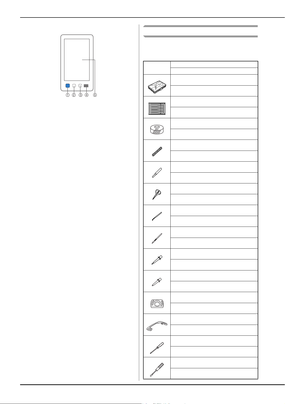
■ Operation panel
1 “Start/Stop” button
Press the “Start/Stop” button to start or stop the machine. The
lighting status and color of the button changes depending on
the operation condition of the machine.
2 Thread trimming button
Press the thread trimming button to trim both the upper and
the bobbin threads.
3 Automatic needle-threading button
Press the automatic needle threading button to thread the
needle.
4 Speaker
5 LCD (touch panel)
Touch the keys that appear on the touch panel to select and
edit patterns and confirm various information.
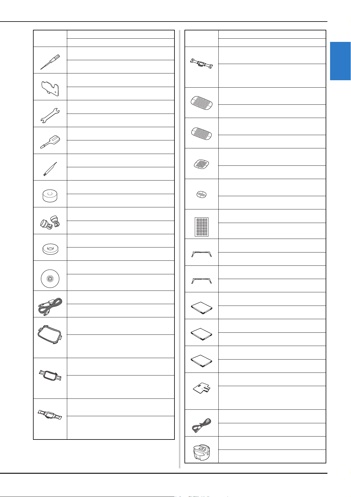
Included accessories
After opening the box, check that the following accessories
are included. If any item is missing or damaged, contact your
authorized Brother dealer.
Lit in red : When the machine cannot start
embroidering
Flashing in green : When the machine can start
embroidering
Lit in green : While the machine is embroidering
Flashing in orange : When the machine can cut the
thread
Off : When the machine is turned off
Part Name
Part Code
1. Accessory case
XC6482-051
2. Needle set × 2
XC6469-001
3. Prewound bobbin × 6
XH3619-001
4. Spool net × 10
S34455-000
5. Seam ripper
XF4967-001
6. Scissors
XF2052-001
7. Tweezers
XC6542-051
8. Touch pen
XA9940-051
9. Threader
XE8362-001
10. Needle changing tool
XF0793-001
11. Needle plate cover
XC6499-151
12. Spacer (on machine)
XF1978-001
13. Phillips screwdriver
XC6543-051
14. Standard screwdriver
X55468-051
GETTING READY
13
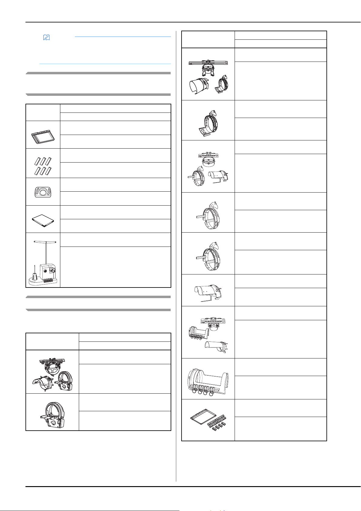
1
15. Allen screwdriver
XC5159-051
16. 3 way screwdriver
XH4670-001
17. Wrench 13 mm × 10 mm
XC6159-051
18. Oiler
D01H2M-001 (Korea)
D01H2N-001 (other areas)
19. Cleaning brush
X59476-051
20. Weight (L)
XC5974-151
21. USB cord clamp × 2
XE8396-002
22. Spool mat × 10
XC7134-051
23. Spool cap × 10
130012-057
24. USB cable
XD1851-051
25. Embroidery frame (extra-large)
360 mm (W) × 200 mm (H)
(14 inches (W) × 7-7/8 inches (H))
PRPH360 (Americas)
PRPH360: XG6733-001 (Europe)
PRPH360CN: 115D02E6024 (China)
PRPH360: 115D02E7024 (other areas)
26. Embroidery frame (large)
180 mm (W) × 130 mm (H)
(7-1/8 inches (W) × 5-1/8 inches (H))
PRH180 (Americas)
PRH180: XG6647-001 (Europe)
PRH180CN: 115D02E6018 (China)
PRH180: 115D02E7018 (other areas)
27. Embroidery frame (medium)
100 mm (W) × 100 mm (H)
(4 inches (W) × 4 inches (H))
PRH100 (Americas)
PRH100: XG6649-001 (Europe)
PRH100CN: 115D02E6017 (China)
PRH100: 115D02E7017 (other areas)
Part Name
Part Code
28. Embroidery frame (small)
60 mm (W) × 40 mm (H)
(2-3/8 inches (W) × 1-1/2 inches (H))
PRH60 (Americas)
PRH60: XG6651-001 (Europe)
PRH60CN: 115D02E6020 (China)
PRH60: 115D02E7020 (other areas)
29. Embroidery sheet (extra large)
360 mm (W) × 200 mm (H)
(14 inches (W) × 7-7/8 inches (H))
XE7158-101
30. Embroidery sheet (large)
180 mm (W) × 130 mm (H)
(7-1/8 inches (W) × 5-1/8 inches (H))
XC5721-051
31. Embroidery sheet (medium)
100 mm (W) × 100 mm (H)
(4 inches (W) × 4 inches (H))
XC5759-051
32. Embroidery sheet (small)
60 mm (W) × 40 mm (H)
(2-3/8 inches (W) × 1-1/2 inches (H))
XC5761-051
33. Embroidery positioning sticker sheets× 4
XE4912-501
34. Embroidery frame holder A
(with white corner cover)
XE7374-001
35. Embroidery frame holder B
(with light gray corner cover)
XE7376-001
36. Operation Manual
This manual
37. Quick Reference Guide
Visit your authorized Brother dealer.
38. Embroidery Design Guide
Visit your authorized Brother dealer.
39. Wide table
PRWT1 (Americas)
PRWT1: XG6731001 (Europe)
PRWT1CN: 115K02E6001 (China)
PRWT1: 115K02E7001 (other areas)
40. Power cord
Visit your authorized Brother dealer.
41.
Bobbin case (on machine)
XC7206-001
Part Name
Part Code
14
Accessories that are included in some
countries or regions
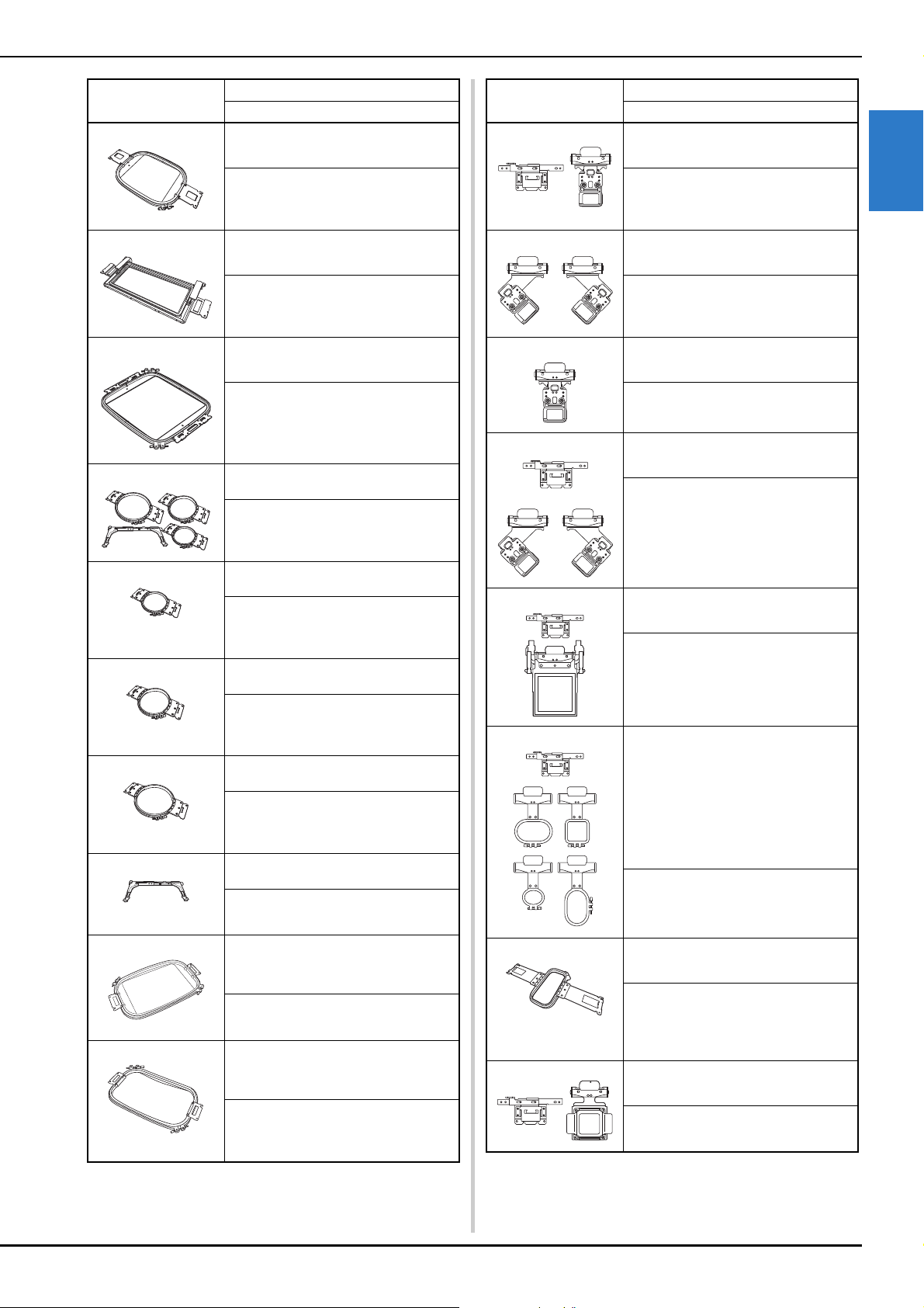
Optional accessories
The following are available as optional accessories to be
purchased separately.
Memo
• The included touch pen can be stored in the touch
pen holder on the back of the operation panel.
(page 11)
Part Name
Part Code
1. Scan frame
XG5300-001
2. Magnet × 6
XF9325-001
3. Needle plate cover (additional)
XC6499-151
4. Embroidery Design Guide (additional)
Visit your authorized Brother dealer.
5. Bobbin winder set
(Refer to page 142.)
PRBW1
Part Name
Part Code
1. Flat brim cap frame set
PRCF5 (Americas)
PRCF5: D01FAB-001 (Europe)
PRCF5AP: 115D02E700J (other areas)
2. Flat brim cap frame
130 mm (W) × 60 mm (H)
(5-1/8 inches (W) × 2-3/8 inches (H))
PRCFH5 (Americas)
PRCFH5: D01FA5-001 (Europe)
PRCFH5AP: 115D02E700G (other areas)
3. Wide cap frame set
PRPCF1 (Americas)
PRPCF1: XE8408-201 (Europe)
PRPCF1CN: 115D02E6001 (China)
PRPCF1: 115D02E7001 (other areas)
4. Wide cap frame
360 mm (W) × 60 mm (H)
(14 inches (W) × 2-3/8 inches (H))
PRPCFH4 (Americas)
PRPCFH4: XG6735-001 (Europe)
PRPCFH4: 115D02E7023 (other areas)
5. Advanced cap frame 2 set
PRCF3 (Americas)
PRCF3: XE2158-201 (Europe)
PRCF3CN: 115D02E6002 (China)
PRCF3: 115D02E7002 (other areas)
6. Advanced cap frame 2
130 mm (W) × 60 mm (H)
(5-1/8 inches (W) × 2-3/8 inches (H))
PRCFH3 (Americas)
PRCFH3: XG6695-001 (Europe)
PRCFH3: 115D02E7008 (other areas)
7. Advanced cap frame
130 mm (W) × 50 mm (H)
(5-1/8 inches (W) × 2 inches (H))
PRCFH2 (Americas)
PRCFH2: 115D02E7007 (other areas*)
* Not available in Europe
8. Mounting jig
PRCFJ2 (Americas)
PRCFJ2: XG6661-001 (Europe)
PRCFJ2: 115D02E7009 (other areas)
9. Cylinder frame set
PRCL1 (Americas)
PRCL1: XG6697-001 (Europe)
PRCL1CN: 115D02E6011 (China)
PRCL1: 115D02E7011 (other areas)
10. Cylinder frame
90 mm (W) × 80 mm (H)
(3-1/2 inches (W) × 3 inches (H))
PRCLH1 (Americas)
PRCLH1: XG6699-001 (Europe)
PRCLH1: 115D02E7010 (other areas)
11. Magnetic sash frame
360 mm (W) × 200 mm (H)
(14 inches (W) × 7-7/8 inches (H))
PRMS360 (Americas)
PRMS360: D01FAN-001 (Europe)
PRMS360AP: 115D02E700K (other
areas)
Part Name
Part Code
GETTING READY
15
1
12. Quilt frame
200 mm (W) × 200 mm (H)
(7-7/8 inches (W) × 7-7/8 inches (H))
PRPQF200 (Americas)
PRPQF200: XG6727-001 (Europe)
PRPQF200CN: 115D02E6025 (China)
PRPQF200: 115D02E7025 (other areas)
13. Border frame
300 mm (W) × 100 mm (H)
(11-3/4 inches (W) × 4 inches (H))
PRPBF1 (Americas)
PRPBF1: XG6729-001 (Europe)
PRPBF1CN: 115D02E6022 (China)
PRPBF1: 115D02E7022 (other areas)
14. Jumbo frame
360 mm (W) × 360 mm (H)
(14 inches (W) × 14 inches (H))
PRPJF360 (Americas)
PRPJF360: XE8405-301 (Europe)
PRPJF360CN:115D02E6003 (China)
PRPJF360: 115D02E7003 (other areas)
15. Round frame set
PRPRFK1 (Americas)
PRPRFK1: XG6725-001 (Europe)
PRPRFK1CN: 115D02E6029 (China)
PRPRFK1: 115D02E7029 (other areas)
16. Round frame
(100 mm (4 inches))
PRPRF100 (Americas)
PRPRF100: XG6737-001 (Europe)
PRPRF100CN: 115D02E6026 (China)
PRPRF100: 115D02E7026 (other areas)
17. Round frame
(130 mm (5 inches))
PRPRF130 (Americas)
PRPRF130: XG6739-001 (Europe)
PRPRF130CN: 115D02E6027 (China)
PRPRF130: 115D02E7027 (other areas)
18. Round frame
(160 mm) (6 inches))
PRPRF160 (Americas)
PRPRF160: XG6741-001 (Europe)
PRPRF160CN: 115D02E6028 (China)
PRPRF160: 115D02E7028 (other areas)
19. Embroidery frame holder C (with
dark gray corner covers)
PRPARMC (Americas)
PRPARMC: XG6743-001 (Europe)
PRPARMC: 115D02E7021 (other areas)
20. Flat frame
300 mm (W) × 200 mm (H)
(11-3/4 inches (W) × 7-7/8 inches
(H))
PRF300 (Americas)
PRF300: XG6693-001 (Europe)
PRF300: 115D02E7016 (other areas)
21. Embroidery frame (extra-large)
300 mm (W) × 200 mm (H)
(11-3/4 inches (W) × 7-7/8 inches
(H))
PRH300 (Americas)
PRH300: XG6645-001 (Europe)
PRH300CN: 115D02E6019 (China)
PRH300: 115D02E7019 (other areas)
Part Name
Part Code
22. Clamp frame S straight set
45 mm (W) × 24 mm (H)
(1-3/4 inches (W) × 7/8 inches (H))
PRCLP45B (Americas)
PRCLP45B: XF2251-001 (Europe)
PRCLP45BCN: 115D02E6012 (China)
PRCLP45B: 115D02E7012 (other areas)
23. Clamp frames S L & R
45 mm (W) × 24 mm (H)
(1-3/4 inches (W) × 7/8 inches (H))
PRCLP45LR (Americas)
PRCLP45LR: XF2255-001 (Europe)
PRCLP45LRCN: 115D02E6013 (China)
PRCLP45LR: 115D02E7013 (other areas)
24. Clamp frame S straight
45 mm (W) × 24 mm (H)
(1-3/4 inches (W) × 7/8 inches (H))
PRCLP45S (Americas)
PRCLP45S: 115D02E7015 (other areas*)
* Not available in Europe
25. Clamp frames S L & R set
45 mm (W) × 24 mm (H)
(1-3/4 inches (W) × 7/8 inches (H))
PRCLP45LRD (Americas)
PRCLP45LRD: 115D02E7014 (other
areas*)
* Not available in Europe
26. Clamp frame M set
100mm (W) × 100 mm (H)
(4 inches (W) × 4 inches (H))
PRCLPM1 (Americas)
PRCLP100B: XG6235-001 (Europe)
PRCLPM1CN: 115D02E600B (China)
PRCLPM1AP: 115D02E700B (other
areas)
27. Compact frame set
70: 70 mm (W) × 41 mm (H) (2-3/4
inches (W) × 1-5/8 inches (H))
50: 50 mm (W) × 50 mm (H) (2
inches (W) × 2 inches (H))
44: 44 mm (W) × 38 mm (H) (1-3/4
inches (W) × 1-1/2 inches (H))
Portrait orientation:
75 mm (W) × 33 mm (H) (2-15/16
inches (W) × 1-5/16 inches (H))
PRHCK1 (Americas)
PRSFK1: XG6209001 (Europe)
PRHCK1CN: 115D02E600A (China)
PRHCK1AP: 115D02E700A (other areas)
28. Sleeve frame
70 mm (W) × 200 mm (H)
(2-3/4 inches (W) × 7-7/8 inches (H))
PRHSL200 (Americas)
PRHSL200: XG5284-001 (Europe)
PRHSL200CN: 115D02E600C (China)
PRHSL200AP: 115D02E700C (other
areas)
29. Magnetic frame set
50 mm (W) x 50 mm (H)
(2 inches (W) x 2 inches (H))
PRMHA50 (Americas)
PRMFA50: XG8593-001 (Europe)
PRMFA50AP: 115D02E700E (other areas)
Part Name
Part Code
16
Setup and transporting precautions
30. Magnetic frame
50 mm (W) x 50 mm (H)
(2 inches (W) x 2 inches (H))
PRMH50 (Americas)
PRMF50: XG8597-001 (Europe)
PRMF50AP: 115D02E700F (other areas)
31. Scan frame set
PRSCANFKIT1: XG8237-001 (Europe)
PRSCANFKIT1AP: 115D02E700D (other
areas)
32. Tubular frame table
PRTT1 (Americas)
PRTT1: D01FAF-001 (Europe)
PRTT1AP: 115K02E7002 (other areas)
33. Embroidery Stand
PRNSTD2 (Americas)
VRPRNSTD: XG3199-001 (Europe)
VRPRNSTDCN: 115Z05E6005 (China)
VRPRNSTD: 115Z05E7005 (other areas)
34. Metal bobbin
100376-051
35. Weight (S)
XC6631-051
36. Embroidery positioning sticker sheets
× 8
SAEPS2 (U.S.A.) / SAEPS2C (Canada)
EPS2: XG6749-001 (Europe)
EPS2CN: 115Z05E600E (China)
EPS2: 115Z05E700E (other areas)
Note
• Visit your nearest authorized Brother dealer for a
complete listing of optional accessories and
embroidery cards available for your machine.
Memo
• Always use accessories recommended for this
machine.
• All specifications are correct at the time of printing.
Please be aware that some specifications may
change without notice.
Part Name
Part Code
SETTING UP THE MACHINE
CAUTION
• The temperature of the operating environment
should be between 5 °C (40 °F) and 40 °C
(104 °F). If the machine is operated in an
environment that is either too cold or too hot,
the machine may malfunction.
• Do not use the machine in a location where it
will be exposed to direct sunlight, otherwise
the machine may malfunction.
• Set up the machine with it’s four adjustable
feet completely in contact with the desk or
table, so that the machine is level.
• Do not put anything under the machine that
could block the ventilation slots found on the
rear underside of the machine, in order to
avoid the possibility of the machine’s motor
overheating, resulting in a fire or in damage to
the machine.
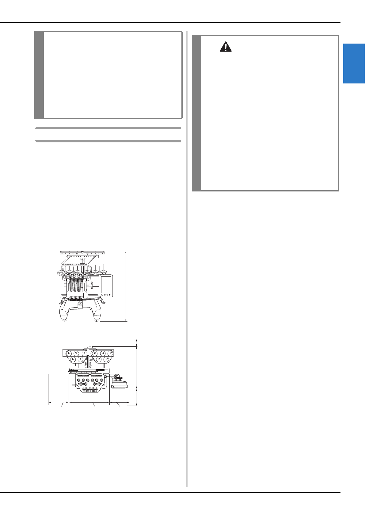
• The machine weight is approximately 41.8 kg
(92 lb). The transporting or setting up of the
machine should be performed by two people.
• When transporting the machine, be sure to
have two people lift the machine from the
bottom at the indicated slots (1). Lifting the
machine from any other area may damage the
machine or result in the machine falling, which
could cause injuries.
• When lightning occurs, turn off the machine
and unplug the power supply cord. Lightning
may cause the machine to malfunction.
• Do not plug in the power supply cord until
setup of the machine is completed, otherwise
injuries may result if the “Start/Stop” button is
accidentally pressed and the machine starts
embroidering.
GETTING READY
17
1
Setup location
Set up the machine in a location that meets the following
requirements.
• Position the machine a minimum of 50 mm (2 inches)
away from the wall.
• Allow sufficient space around the machine.
• Place no objects within the moving range of the
embroidery frame.
• Set-up machine near an electrical outlet.
• Use a level and stable surface, such as a desk or stand.
• Use a surface that can support the weight of the machine
(about 41.8 kg (92 lb)).
• Allow open space around the ventilation slots found on
the rear underside of the machine.
• When lubricating the machine, wear protective
eyeglasses and gloves to prevent the oil or
grease from getting into your eyes or on your
skin. Do not put the oil or grease into your
mouth. Keep the oil and grease out of the reach
of children.
• While attaching or detaching an embroidery
frame or other included accessory or while
maintaining the machine, be careful nothing
interferes with the moving parts of the
machine.
790 mm
(31-1/8 inches)
Minimum of
50 mm
(2 inches)
589 mm
(23-1/4 inches)
More than
350 mm
(13-3/4 inches)
More than
210 mm
(8-1/4 inches)
561 mm
(22 inches)
More than
220 mm
(8-3/4 inches)
CAUTION
• In order to prevent malfunctions or damage,
do not set up the machine in a location
exposed to the following conditions.
- Liquids, such as water
-Extreme dust
- Direct sunlight
- Extremely high or extremely low
temperatures. The operating environment
should be between 5 °C (40 °F) and 40 °C
(104°F).
- Insufficient space
- Objects within the moving range of the
embroidery frame
- Blocked ventilation slots
- An unstable surface
• Do not use extension cords or multi-plug
adapters with many other appliances plugged
in to them.
18
Setting up the machine
When setting up the machine, adjust the legs so that the
machine is steady.
a
Make sure that all packing tape affixed to the machine
is peeled off and that all packing material is removed.
b
Set up the machine while making sure that there is
sufficient space around it.
For details on the setup location, refer to page 17.
c
Adjust the legs so that the machine is steady.
Use the included wrench to loosen the lock nut on the
leg that you wish to adjust.
The foot can be turned.
d
Use the included wrench to turn the adjustable foot
nut on the foot.
Turning the nut in direction 1 lengthens the leg; turning
the nut in direction 2 shortens the leg.
• Adjust all four legs so that they securely contact the
desk or table, and the machine is level.
e
After adjusting the legs to the desired length, use the
included wrench to tighten the nuts.
f
Press down on each corner of the machine to check
that it is stable.
If it is still unstable, perform steps
c through e again
to adjust the legs.
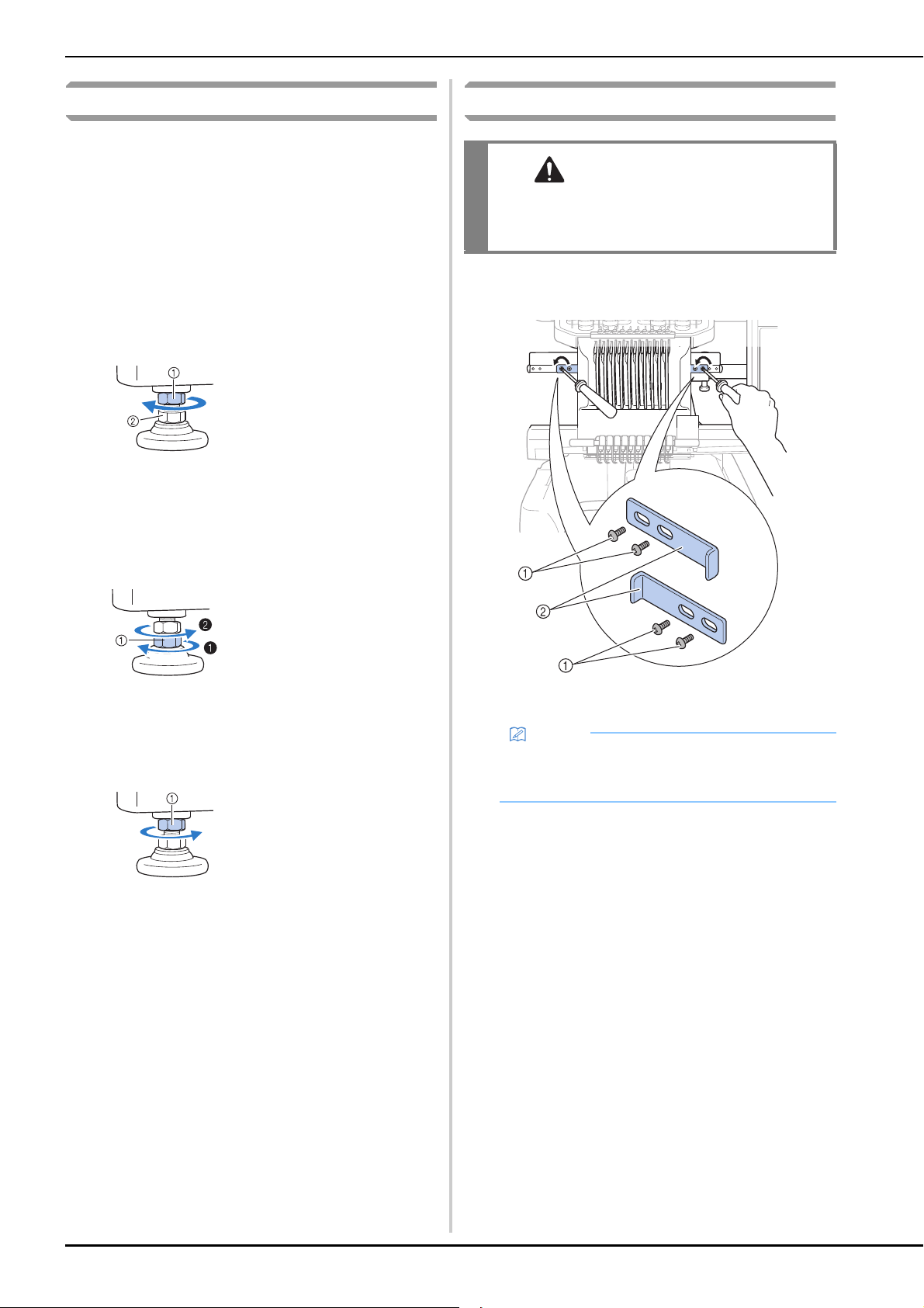
Remove the fixing plates
a
Using the included Phillips screwdriver, remove each
of screws on the fixing plates.
1 Screws
2 Fixing plates
1 Lock nut
2 Adjustable foot nut
1 Adjustable foot nut
1 Lock nut
CAUTION
• Remove the fixing plates before turning on the
machine, otherwise the machine may
malfunction.
Memo
• After removing the fixing plates, be sure to keep
them to be used again. Before transporting the
machine, consult your authorized Brother dealer.
GETTING READY
19
1
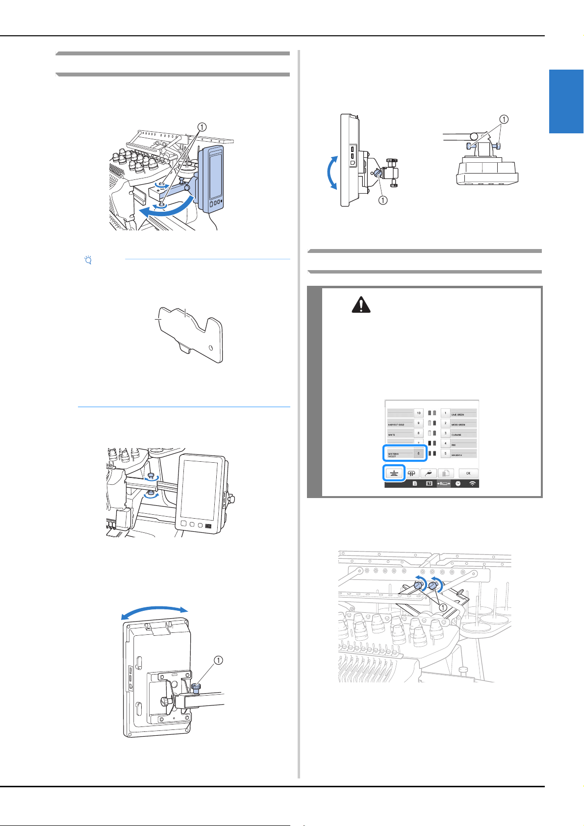
Adjusting the operation panel position
a
Loosen 2 thumb screws to bring the operation panel
forward.
1 Thumb screws
b
Adjust the operation panel to an easy-to-operate
position, and then tighten the thumb screws.
c
Adjust the orientation of the operation panel.
Loosen the thumb screw, adjust the operation panel to
an easy-to-view orientation, and then tighten the thumb
screw.
1 Thumb screw
d
Adjust the angle of the operation panel.
Loosen the 2 thumb screws behind the operation panel,
adjust the operation panel to an easy-to-view angle, and
then tighten the thumb screws.
1 Thumb screws
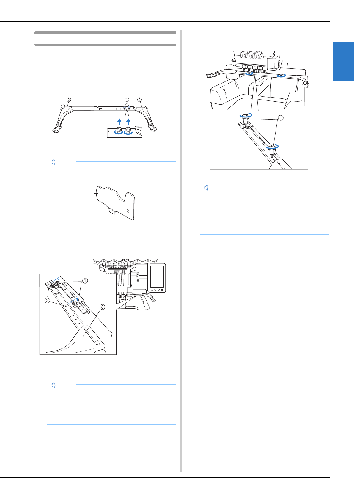
Preparing the thread guide assembly
a
Loosen the two thumb screws on top of the thread
guide assembly support.
1 Turn the screw counterclockwise three or four times to
loosen it.
Note
• Using the 3 way screwdriver included, loosen and
firmly tighten the thumb screws.
1 Use this part to tighten the upper and lower
thumb screws.
2 Use this part to tighten the left and right thumb
screws.
a
b
(Side view) (Top view)
CAUTION
• When setting up the thread guide assembly, set
it up with the needle bar 6 position selected,
otherwise the machine may malfunction.
(Refer to “Moving and threading a selected
needle bar” on page 86 for moving the needle
bar.)
20
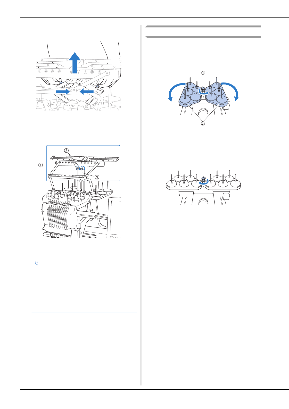
b
Grab the grips on the thread guide assembly support
and push toward the middle.
c
After the thread guide assembly support is extended
and the thread guide assembly is raised to its highest
position, tighten the two thumb screws to secure the
thread guide assembly in place.
1 Thread guide assembly
2 Thumb screws
3 Thread guide assembly support
Preparing the spool stand
a
Loosen the thumb screw two or three turns, and then
fold out the spool stand.
Rear view
1 Thumb screw
2 Spool stand
b
After the spool stand is fully opened up, tighten the
thumb screw.
Rear view
Secure the spool stand in the opened position.
Note
• If the thumb screws are not loosened enough, it
may not be easy to move the thread guide
assembly support. Do not apply extreme force
when moving the thread guide assembly support.
Be sure that the thumb screws are loosened well
enough before moving the part.
• Be sure to tighten each thumb screw well enough
that the thread guide assembly support is secured.
GETTING READY
21
1
Attaching the embroidery frame holder
a
Use the embroidery frame holder appropriate for the
embroidery frame that you are using (page 66 to
page 68).
b
Remove the two thumb screws of the embroidery
frame holder.
1 Thumb screws
2 Corner covers
c
Align the holes in the embroidery frame holder with
the pins on the frame-mounting plate of the carriage.
1 Pins on the frame-mounting plate
2 Holes in the embroidery frame holder
3 Corner covers
d
Secure the embroidery frame holder with the two
thumb screws removed in step
b.
1 Thumb screws
This completes the preparation of the machine.
Note
• Using the 3 way screwdriver included, loosen and
firmly tighten the thumb screws.
1 Use this part to tighten the thumb screws of the
embroidery frame holder.
Note
• Each embroidery frame holder has different color of
corner cover.
Holder A: White corner covers
Holder B: Light gray corner covers
Holder C: Dark gray corner covers (Optional)
a
Note
• Two types of embroidery frame holders are
included with this machine. Embroidery frame
holder A is used with the four included embroidery
frames. (page 66)
• Refer to page 67 for hoops used with frame holder
B and other optional frame holders.
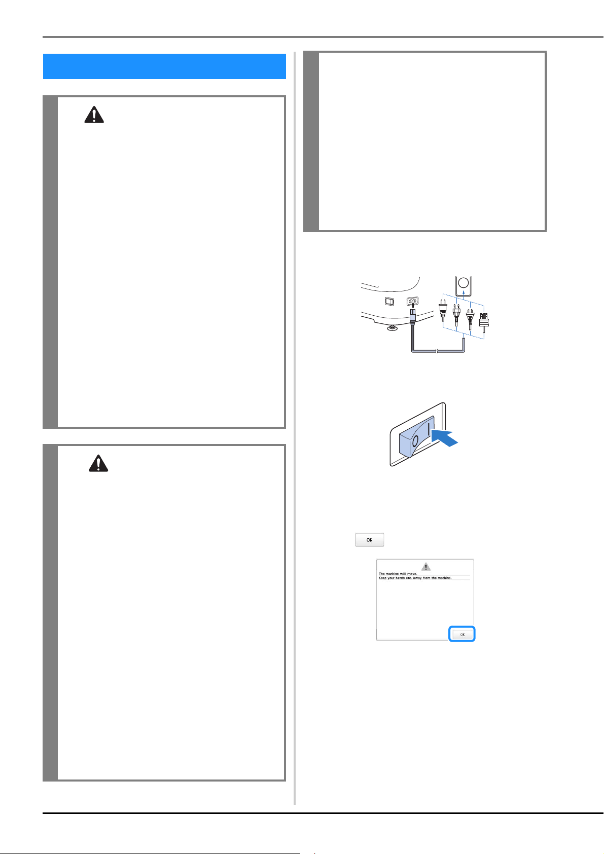
22
a
Insert the power supply cord into the power cord
receptacle, then insert the plug into a wall outlet.
b
Switch on the main power switch on the right side of
the machine to “I”.
The LCD screen comes on.
c
When the machine is turned on, the opening movie is
played. Touch anywhere on the screen to display the
message below.
d
Touch .
The pattern type selection screen appears, and the
“Start/Stop” button lights up in red.
TURNING ON THE MACHINE
WARNING
• Use only regular household electricity for the
power source. Using other power sources may
result in fire, electric shock, or damage to the
machine.
• Make sure that the plugs on the power supply
cord are firmly inserted into the electrical
outlet and the power supply cord receptacle
on the machine. Otherwise, a fire or electrical
shock may result.
• Do not insert the plug on the power supply
cord into an electrical outlet that is in poor
condition.
• If any of the following occur, turn off the
machine and unplug the power supply cord,
otherwise a fire, an electric shock or damage
to the machine may result.
• When you are away from the machine.
• After using the machine.
• If a power outage occurs while the machine is
being operated.
• If the machine is not operating properly, for
example, when there is a loose or cut
connection.
• During electrical storms.
CAUTION
• Be sure to use the included power cord for this
machine.
• Do not plug this machine in with extension
cords or multi-plug adapters with any other
appliances plugged into them, otherwise a fire
or an electric shock may result.
• Do not plug in or unplug the power supply
cord with wet hands, otherwise an electric
shock may result.
• When unplugging the power supply cord, be
sure to first turn off the machine, and then
grasp the plug when unplugging the cord.
Pulling on the cord may damage it or result in
a fire or an electric shock.
• Do not allow the power supply cord to be cut,
damaged, modified, forcefully bent, pulled,
twisted, or bundled. In addition, do not place
heavy objects on the cord or expose it to heat,
otherwise damage to the cord, fire or an
electric shock may result. If the power supply
cord or its plug is damaged, stop using the
machine, and then take the machine to your
authorized Brother dealer for repairs before
continuing use.
• If the machine is not to be used for a long
period of time, unplug the power supply cord,
otherwise a fire may result.
•For U.S.A. only
This appliance has a polarized plug (one blade
wider than the other). To reduce the risk of
electrical shock, this plug is intended to fit in a
polarized outlet only one way.
If the plug does not fit fully in the electrical
outlet, reverse the plug. If it still does not fit,
contact a qualified electrician to install the
proper electrical outlet. Do not modify the
plug in any way.
GETTING READY
23
1
e
The carriage moves to its initial position.
• If the number 1 needle bar is not already at the
embroidering position, the needle bar case moves
and the number 1 needle bar moves to the
embroidering position.
f
Set the main power switch to “O” to turn off the
machine.
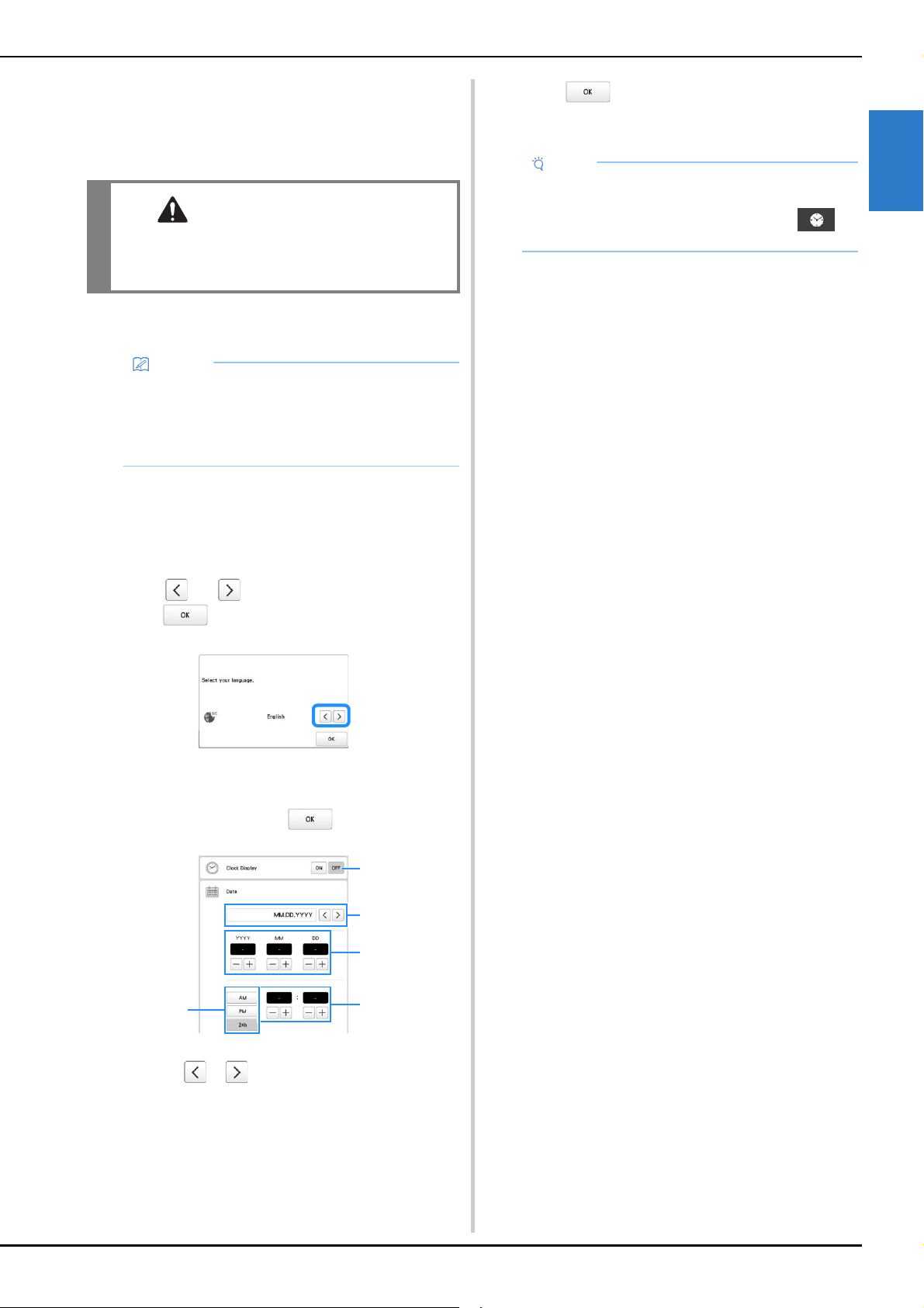
■ Setting your machine for the first time
When you first turn on the machine, set the language and
time/date to your language and local time/date. Follow the
procedure below when the settings screen appears
automatically.
a
Touch and to set your local language and then
touch .
The carriage moves to its initial position.
b
The message screen, confirming if you want to set
time/date, appears. Touch .
1 Select [ON] to display time/date on the screen.
2 Touch or to select the date display format.
3 Set the year [YYYY], month [MM] and date [DD].
4 Select whether 24h or 12h setting to display.
5 Set the current time.
c
Touch to start using your machine.
The clock starts from 0 second of the time you set.
CAUTION
• Make sure to keep your hands and other items
away from the carriage, in order to prevent
any injuries.
Memo
• If the machine is turned off in the middle of
embroidering, the machine will automatically save
the design position when turned on again. At that
time, you will be asked if you wish to continue
embroidering or begin a new operation. (page 97)
4
3
5
2
1
Note
• The time/date you set may be cleared, if you don't
turn on the machine for an extended period of time.
• Time setting is also available by touching on
the bottom right of the LCD screen.
24
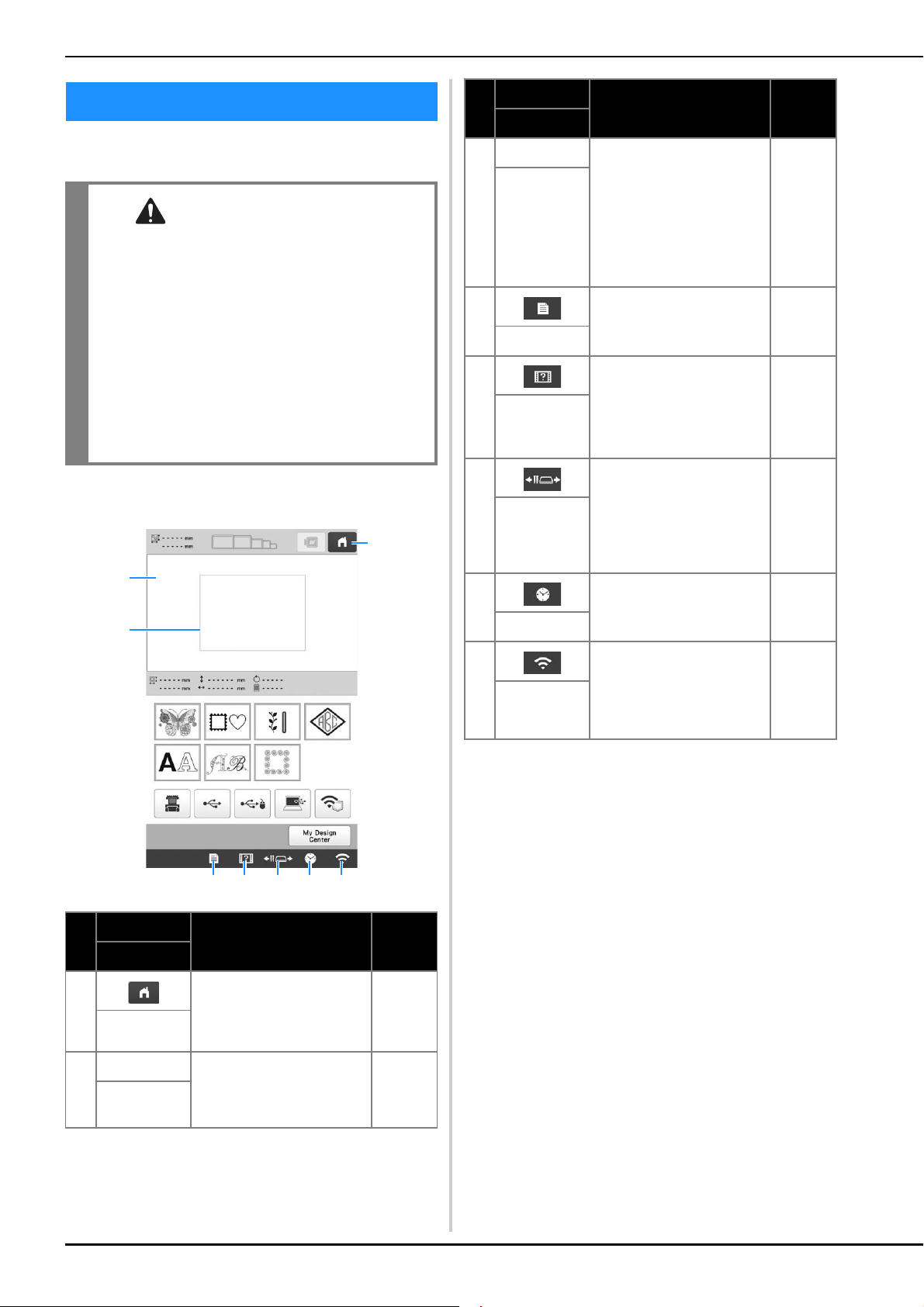
Touch the LCD screen, or a key, with your finger or the
included touch pen to select a machine function.
■ Pattern type selection screen
* The keys in the table above appear and can be used
in most of the screens described later in this manual.
LCD SCREEN
CAUTION
• Only touch the screen with your finger or the
touch pen included with the machine. Do not
use a mechanical pencil, screwdriver or any
other hard or sharp object. In addition, do not
touch the screen with extreme pressure.
Otherwise the screen may be damaged.
• All or part of the screen may sometimes
become darker or lighter due to changes in the
surrounding temperature or other changes in
the environment. This is not a sign of a
malfunction. If the screen is difficult to read,
adjust its brightness.
No.
Display
Function Page
Key Name
1 Cancel all operations
previously performed and
return to the initial pattern
type selection screen.
–
Home key
2 – This area displays the
selected pattern.
123
Pattern
display area
3
1
2
4 5 6 7 8
3 – Shows the available
embroidering area for the
attached embroidery frame.
The embroidery frame
indications, the grid lines
and other display settings
can be specified from the
machine settings screen.
123
Embroidering
area line
4 Change the machine
settings.
25
Settings key
5 Check a machine
operation.
28
Machine
operations
guide key
6 Move or thread a selected
needle bar, to position the
carriage, or to oil the
machine so the embroidery
frame can easily be
removed or attached.
66, 86
Needle bar/
Frame move
key
7 Set the clock to your local
time.
23
Clock key
8 Specify the wireless LAN
settings. Also, this key
shows the machine’s
wireless LAN signal
strength.
27
Wireless LAN
key
No.
Display
Function Page
Key Name
GETTING READY
25
1
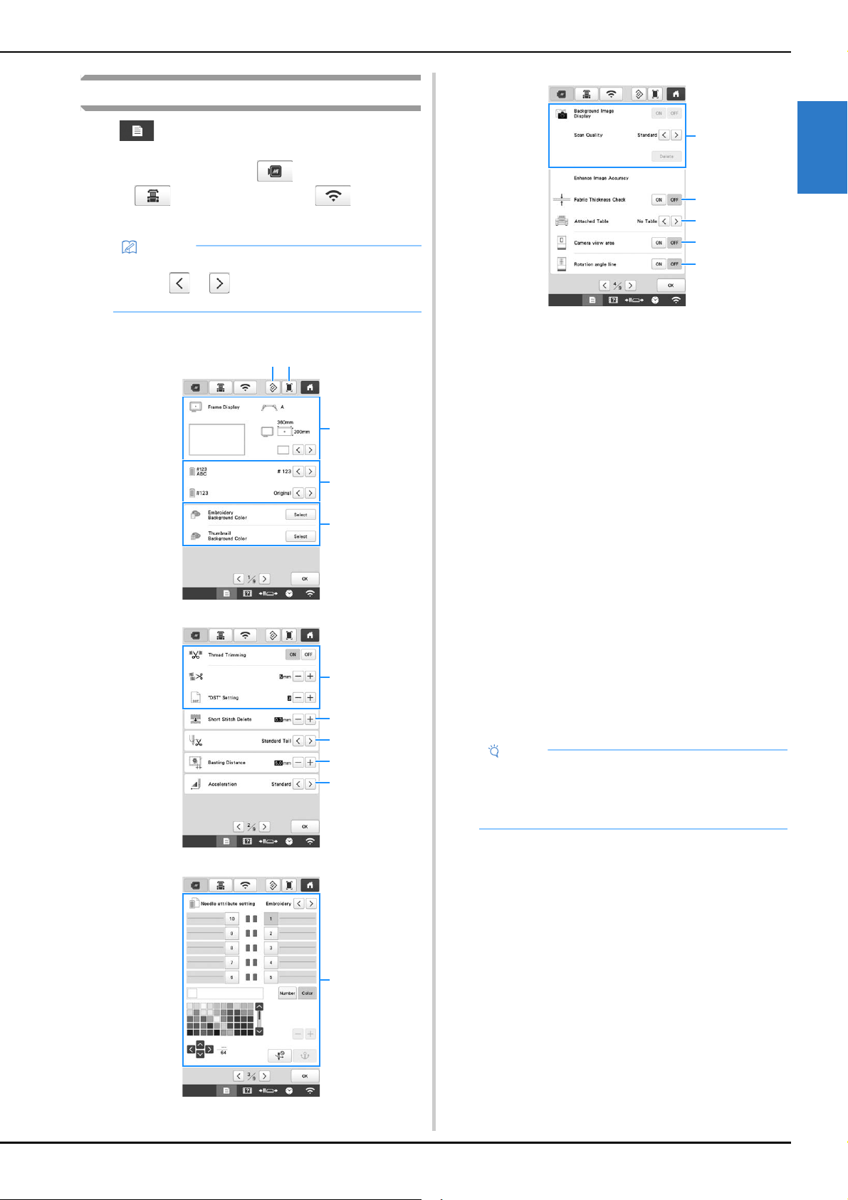
Using the settings key
Touch to change the default machine settings (light,
volume, speaker volume, opening display etc.). To display the
different settings screens, touch for “Embroidery
settings”, for “General settings”, or for
“Wireless LAN settings”.
■ Embroidery settings
1 The settings on the page containing this key will be
reverted to their defaults.
2 An image of the current settings screen can be saved on
USB media.
3 The guides (center point marker and grid) for the pattern
display area can be specified. (page 123)
4 The color information in the thread color sequence
display and the needle bar thread information can be
switched to the color name, the thread brand and color
number or the embroidering time. (page 123)
5 Depending on the color of the embroidery, changing the
background color of the pattern display area and
thumbnails may make them more visible and easier to
select.
6 Specifies whether or not jump stitches are cut. In
addition, the jump stitch length can be specified. When
using Tajima embroidery data (.dst), you can specify
whether or not the thread is cut according to the
specified number of jump codes. (page 123)
7 Specifies the length of short stitches that are to be
deleted. (page 124)
8 Specifies the length of upper thread that remains
threaded through the needle after the thread is trimmed
(length of thread passed through the eye of the needle).
(page 124)
9 Specify the distance between the pattern and the
basting stitching. (page 124)
0 Specifies the acceleration from the initial speed (when
embroidery begins) until the maximum embroidery
speed is reached.
A A specific thread color can be set to a needle bar. The
specified color remains assigned to the needle bar until
the setting is cancelled. You can also specify the
maximum embroidery speed for a needle bar as well as
cancel automatic needle threading. This feature is not
accessible through the embroidering screen. (page 121)
B Select whether or not the fabric is displayed in the
background. (page 72)
C When the fabric is scanned and displayed as a
background image, the thickness of the fabric can be
checked to ensure that the camera correctly detects the
fabric. (page 74)
D Before scanning the fabric to display it as a background
image for a pattern or before using the built-in camera to
display a camera image of the fabric, select the table
installation setting. (page 73)
E A blue box can be displayed in the embroidering settings
screen to indicate the area detected by the camera.
F Grid line can be displayed in the camera screen to
support setting the pattern at the desired angle.
Memo
• The machine default setting is highlighted.
• Touch or to display a different settings
screen.
5
4
3
21
6
0
9
8
7
A
Note
• If the settings for [“DST” Setting] 6 or [Short Stitch
Delete] 7 are changed from the previous setting,
the new settings are applied to the subsequent
embroidery.
B
E
D
C
F
26
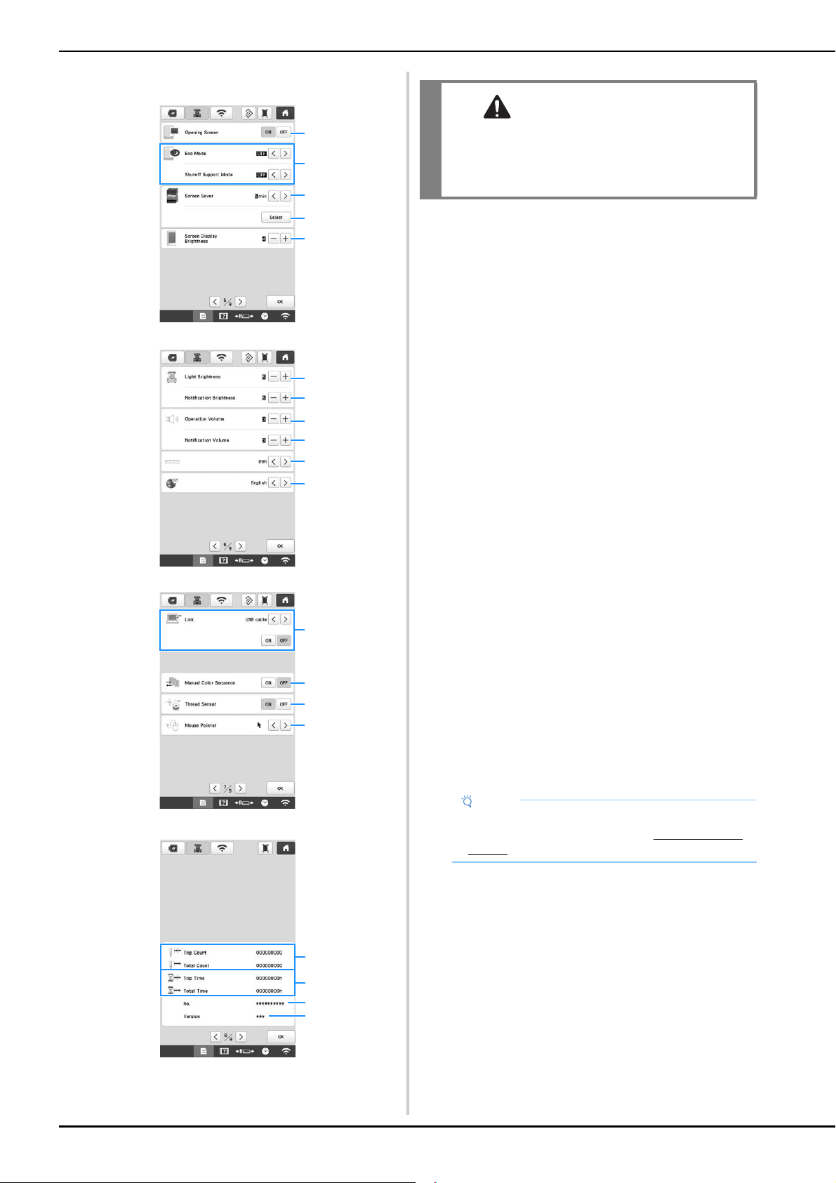
■ General settings
1 The machine can be set so that the opening screen is
either displayed ([ON]) or not displayed ([OFF]) when the
machine is turned on.
2 Select settings for the [Eco Mode] and [Shutoff Support
Mode]. (page 27)
3 Select the length of time until the screen saver appears.
4 Select the image of the screen saver. (page 27)
5 Adjust the brightness of the screen display.
6 Adjust the brightness of the embroidery light.
7 Adjust the brightness of the embroidery light when
lighting effects are used to notify that the thread spool
must be changed or an error has occurred.
8 Adjust the volume of operation beep. Increase the
number for louder volume, decrease for softer volume.
9 Adjust the volume of error notification. Increase the
number for louder volume, decrease for softer volume.
0 Select the display units for embroidering (mm/inch).
A Select the display language. The keys and messages
appear in the selected language.
B Select the Link function [ON] or [OFF]. You can choose
the USB cable connection or the wireless LAN
connection. (page 132)
C Set the [Manual Color Sequence] [ON] or [OFF].
(page 58)
D Turn both the upper and bobbin thread sensors [ON] or
[OFF]. If it is turned [OFF], the machine can be used
without upper thread.
E Change the shape of the pointer when a USB mouse is
used.
F [Total Count] shows the total number of stitches
embroidered, and [Trip Count] shows the number of
stitches that have been embroidered since the
machine’s last maintenance.
G [Total Time] shows the total amount of time that the
machine has been used, and [Trip Time] shows the
amount of time that the machine has been used since
the machine’s last maintenance.
*Use counters F and G as a standard for performing
periodic maintenance and for receiving
maintenance for the machine.
H Shows the internal machine number for this machine.
I Shows the version of the software installed on this
machine.
2
4
5
3
1
A
0
6
7
8
9
B
E
D
C
F
I
H
G
CAUTION
• When [Thread Sensor] is set to [OFF], the
machine cannot detect tangled upper thread.
Continuing to use the machine with tangled
thread may cause damage.
Note
• Install the latest software. Check with your local
authorized Brother dealer or at “ http://s.brother/
cubah/ ” for available updates (page 192).
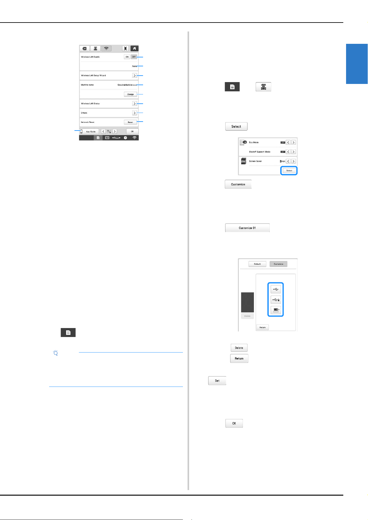
GETTING READY
27
1
■ Wireless LAN settings
1 Enable/Disable the wireless LAN function.
2 Shows the connected SSID.
3 Set the machine to connect wireless LAN function.
4 Shows the machine name used on the wireless network.
This name is used when transferring files from the
machine to the embroidery editing software (PE-DESIGN
version 11 or later).
5 Change the machine name used on the wireless
network.
6 Check the wireless LAN status.
7 Display other menus.
8 Reset network operations.
9 Display the introduction to the application.
■ Setting the [Eco Mode] and the [Shutoff
Support Mode]
You can save the machine power by setting the [Eco
Mode] and the [Shutoff Support Mode]. If you leave the
machine turned on without using it for the set period of
time, the machine enters in each mode.
[Eco Mode]:
Machine will enter a sleep mode after the set period of
time. Touch the screen or press the “Start/Stop” button to
continue operating.
[Shutoff Support Mode]:
Machine will turn off after set period of time. Turn the
machine off and then back on to restart operating.
Touch to display [Eco Mode] and [Shutoff Support
Mode]. (page 26)
■ Changing the screen saver image
You can select your own personal images for the screen
saver of your machine.
Before changing the screen saver image, prepare the
image on your computer or USB media.
For details on compatible image files, refer to
“SPECIFICATIONS” on page 190.
a
Touch , then .
The general settings screen appears.
b
Locate [Screen Saver] in the general settings screen.
c
Touch .
d
Touch .
e
Connect the USB media or the computer (using a USB
cable) that contains your personal image to the USB
port of the machine.
f
Touch to select the first image.
g
Select the device that is connected.
A list of your personal images appear on the screen.
• Touch to delete the selected image.
• Touch to return to the previous screen.
h
Touch a file name to select image and then touch
.
The selected image is stored on your machine.
i
Repeat steps f through h to set the remaining
images.
j
Touch to return to the original screen.
Note
• If you turn off the machine while the machine is in
the [Eco Mode] or the [Shutoff Support Mode], wait
for about 5 seconds before turning on the machine
again.
5
6
4
1
2
3
7
8
9
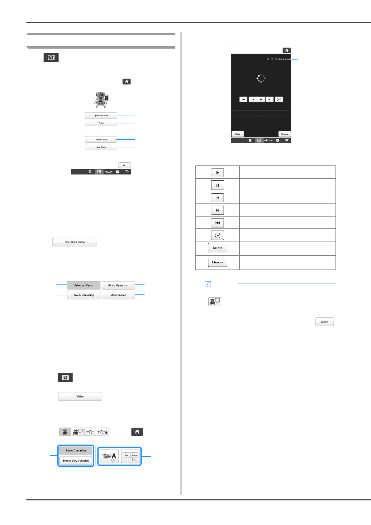
28
Using the machine help
Touch to display the machine help screen.
Functions are available from the screen shown below.
1 Explanation for upper threading, installing the bobbin,
preparing to embroider a pattern, and how to use the
machine (page 28)
2 Tutorial videos or MPEG-4 (MP4) videos from USB
media (page 28, page 29)
3 Display the link information to Brother support website.
4 Display the introduction to the application.
■ Using the operation guide function
Touch to display the screen shown
below. Categories are displayed at the top of the screen.
Touch a key to see more information about that category.
Some of the functions are described in the movies. Watch
these movies for a better understanding of the functions.
1 Information about the main parts of the machine and
their functions
2 Information about threading the machine, hooping the
fabric in the embroidery frame, etc.
3 Information about troubleshooting
4 Information about cleaning the machine, etc.
■ Playing a tutorial video
This machine provides tutorial videos on how to use the
machine.
a
Touch .
b
Touch .
c
Select the category and the tutorial video.
1 Category
2 Tutorial video
The selected tutorial video begins playing.
d
Play the tutorial video.
1 Number of seconds elapsed/Total number of seconds
Operation keys
e
After you are finished playing the video, touch .
1
2
3
4
2
4
1
3
2
1
Play
Pause
Skip back 10 seconds
Skip forward 10 seconds
Return to beginning
Repeat
Delete video (when playing from the
machine’s memory)
Save to machine (when playing from USB
media)
Memo
• A frequently viewed tutorial video can be saved to
(favorites) of the machine, from where it can
be played.
1
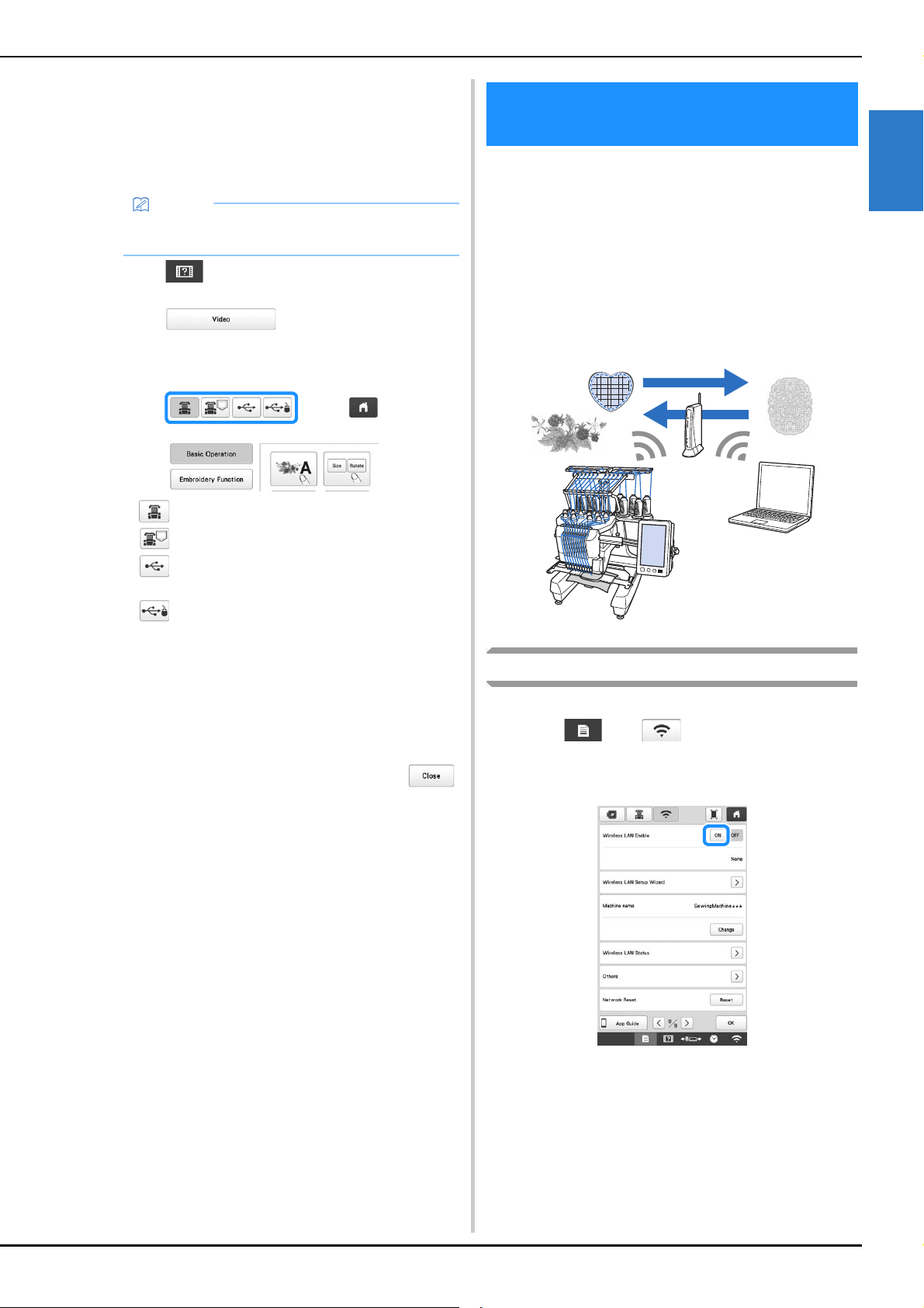
GETTING READY
29
1
■ Playing MPEG-4 (MP4) videos
Your MP4 videos can be played from USB media. In
addition, the MP4 video can be saved to the machine so
that a tutorial video on creating a project, for example,
can be viewed at any time. For details on compatible
video files, refer to “SPECIFICATIONS” on page 190.
a
Touch .
b
Touch .
c
Select the device where the video is saved.
• : play a tutorial video
• : Play a video saved on the machine (favorites)
• : Play a video from USB media plugged into the
USB port
• : Play a video from USB media plugged into the
USB port for mouse
d
Select the video that you want to play.
e
Play the video.
* Use the operation keys as described in “Playing a
tutorial video” on page 28.
f
After you are finished playing the video, touch .
This machine supports a wireless network connection.
Using this function, an embroidery pattern edited in
embroidery editing software (PE-DESIGN version 11 or
later) with wireless transfer functions can be transferred to
the machine from a computer. Embroidery patterns can be
transferred from the machine to the embroidery editing
software. The machine and computer must be connected
to the same network. For detailed procedures, refer to the
manual for the embroidery editing software. The wireless
network must be set up and enabled to use the special
application to transfer images to the machine.
Enabling a wireless network connection
The machine can be connected to your wireless network.
a
Touch , then .
b
Set [Wireless LAN Enable] to [ON].
The machine prepares for wireless transmission.
Memo
• Some type of MP4 file cannot viewed with the
machine.
WIRELESS NETWORK
CONNECTION FUNCTIONS

30
■ Requirements for a wireless network
connection
The wireless network connection complies with IEEE
802.11 n/g/b standards and uses the 2.4 GHz frequency.
Setting up the wireless network connection
There are multiple ways to set up the wireless network
connection. We recommend the method that uses the wizard
on this machine.
■ Using the wizard to set up the wireless
network connection
a
In order to connect your machine to a wireless
network, the security information (SSID and network
key) for your network will be required. The network
key may also be called a password, security key or
encryption key. Find your security information and
note it in the table below.
b
Touch beside [Wireless LAN Setup Wizard].
A list of available SSIDs appears.
c
Touch beside the SSID that was noted.
The screen for entering the network key (password)
appears.
d
Enter the network key (password) that was noted, and
then touch .
Memo
• A wireless network cannot be set up with WPA/
WPA2 Enterprise.
SSID Network Key (Password)
Memo
• The wireless network connection cannot be set up
if you do not have the security information.
• How to find the security information
1 Check the manual provided with your network.
2 The default SSID may be the manufacturer's
name or the model name.
3 If you cannot find the security information,
contact the manufacturer of the router, your
network administrator or your Internet provider.
Memo
• If the SSID that was noted does not appear in the
list, touch .
• If the SSID that was noted is not displayed, specify
it as described below.
1 Select in the list of SSIDs.
2 Enter the desired network SSID, and then touch
.
3 Select the authentication method and
encryption mode.
• If the machine had already been connected to the
home network, touch , and then select the
saved SSID.
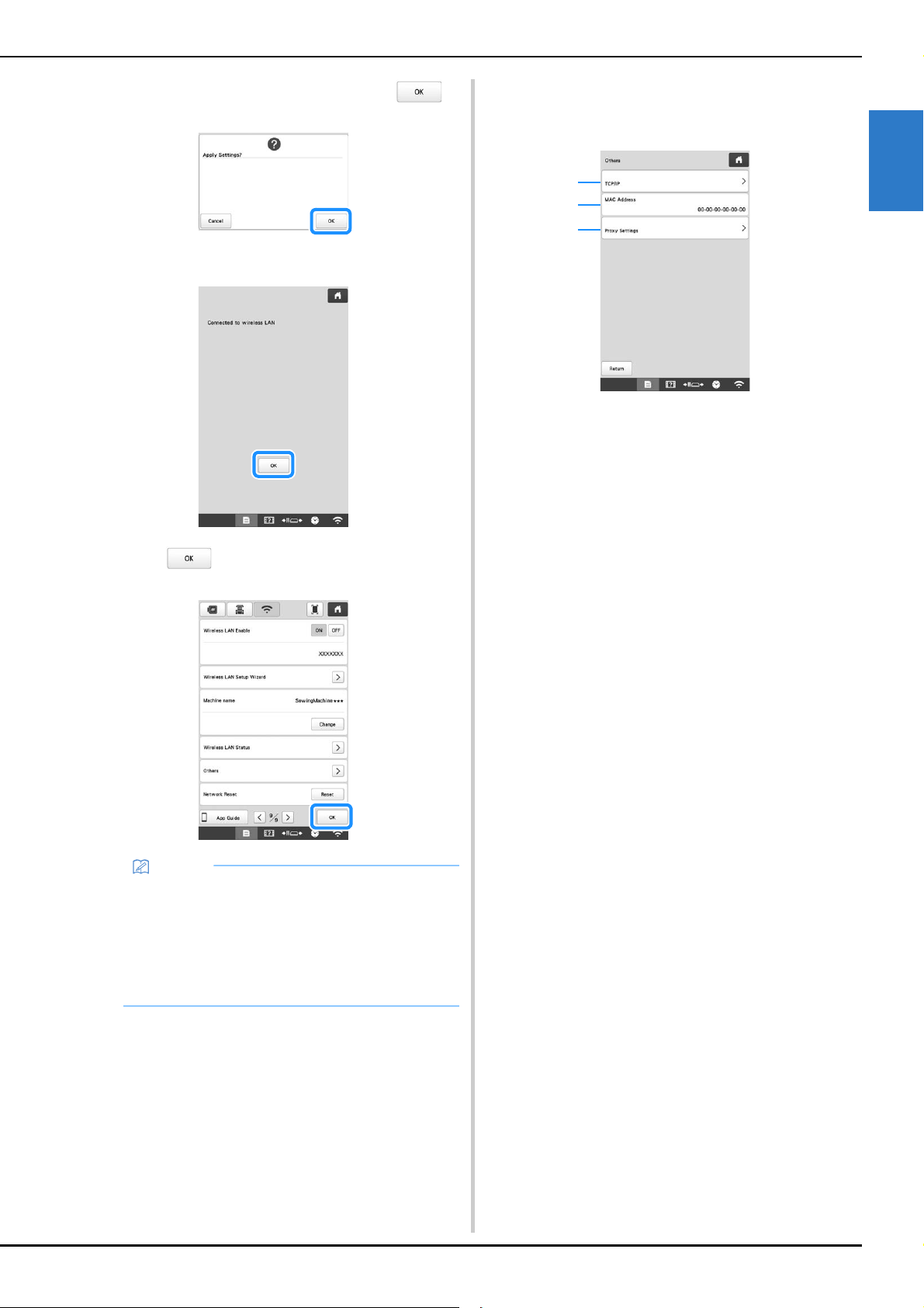
GETTING READY
31
1
e
When the following message appears, touch .
When a connection is established, the following
message appears.
f
Touch to exit the setup.
■ Using the [Others] menu to set up the wireless
network connection
The [Others] menu contains the following items.
1 TCP/IP settings can be manually entered.
2 Shows the MAC address.
3 Use when proxy settings are required.
Memo
• While connected, the signal strength is indicated
by the icon in the lower-right corner of the display.
• Once a wireless network connection has been set
up, a connection will be established each time the
machine is turned on. However, [Wireless LAN
Enable] in the network settings screen must remain
set to [ON].
1
2
3
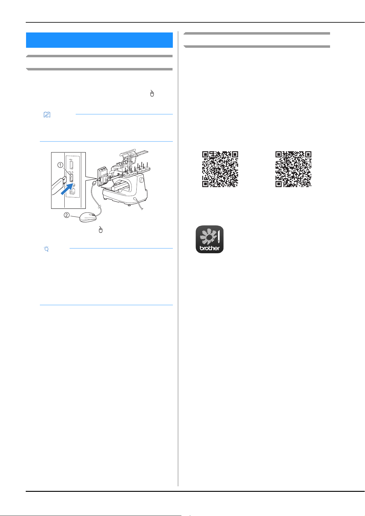
32
Using a USB mouse
A USB mouse, connected to the machine, can be used to
perform a variety of operations in the screens.
Connect a USB mouse to the USB port marked with . You
can also connect a USB mouse to the other USB port.
1 USB port marked with
2 USB mouse
Monitoring App
With the monitoring app installed on your smart device and
the machine and smart device connected to the same wireless
network, you can check the operating status of the machine.
You can also check when to change the thread spool and
what thread spool color to change to. In addition, you can
receive notifications when the machine stops.
a
Connect the machine to your wireless network.
(page 29)
b
Use a QR Reader app on your smart device to capture
the appropriate QR code (Android™ or iOS) and visit
the Google Play™ or App Store.
c
Install [My Stitch Monitor] to monitor embroidering.
OTHER FUNCTIONS
Memo
• Use a basic computer mouse to operate the
machine functions. Some USB mouse devices may
not be compatible with this machine.
Note
• A USB mouse can be connected or disconnected
at any time.
• The left mouse button can be used to perform
operations such as choosing a design and
choosing menu keys.
• The mouse pointer does not appear in the screen
saver.
Google Play™ App Store
My Stitch Monitor
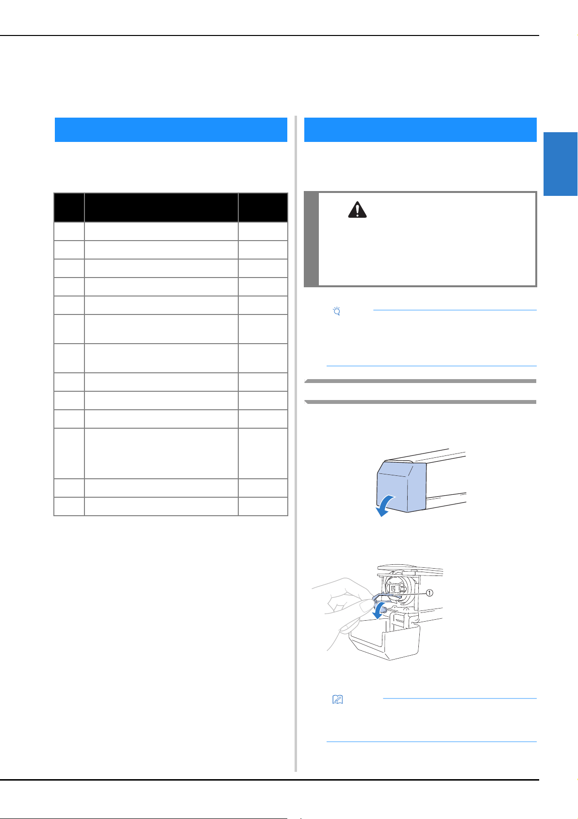
BASIC EMBROIDERY
33
2
Basic embroidering procedures are described below.
Check the overall procedure below, before operating the
machine.
When the machine is purchased, only the bobbin case is
installed in the hook. Insert a bobbin wound with bobbin
thread for embroidering.
Removing the bobbin case
a
Open the hook cover.
Pull the hook cover toward you.
b
Pull the thread picker toward you if it was not pulled
toward the front.
To gain access to the bobbin case easily, pull the thread
picker toward front.
Chapter 2
BASIC EMBROIDERY
BASIC PROCEDURES
Step Operation
Reference
Page
1 Install the bobbin. 33
2 Turn on the machine. 22
3 Select an embroidery pattern. 35
4 Edit the embroidery pattern. 44
5 Check the previewed image. 60
6
Hoop the fabric in the embroidery
frame.
61
7
Attach the embroidery frame to the
machine.
64
8 Specify the embroidering settings. 69
9 Check the embroidery area. 72
10 Thread the upper threads. 81
11
Touch the “Start/Stop” button to start
embroidering.
(Once embroidering is completed, the
machine automatically stops.)
87
12 Remove the embroidery frame. 90
13 Turn off the machine. 22
INSTALLING THE BOBBIN
CAUTION
• Be sure to use prewound bobbins (Fil-Tec/
TRU-SEW POLYESTER “Filaments”) or metal
bobbins designed specifically for this machine.
• When winding a bobbin, use optional bobbin
winder (page 142) and metal bobbins.
Note
• Before starting to embroider make sure that there
is enough bobbin thread for the pattern.
• Make sure to clean the bobbin case every time the
bobbin is changed. (page 175)
1 Thread picker
Memo
• Thread picker is a device that is used to hold the
thread when beginning to embroider or when
trimming the thread.
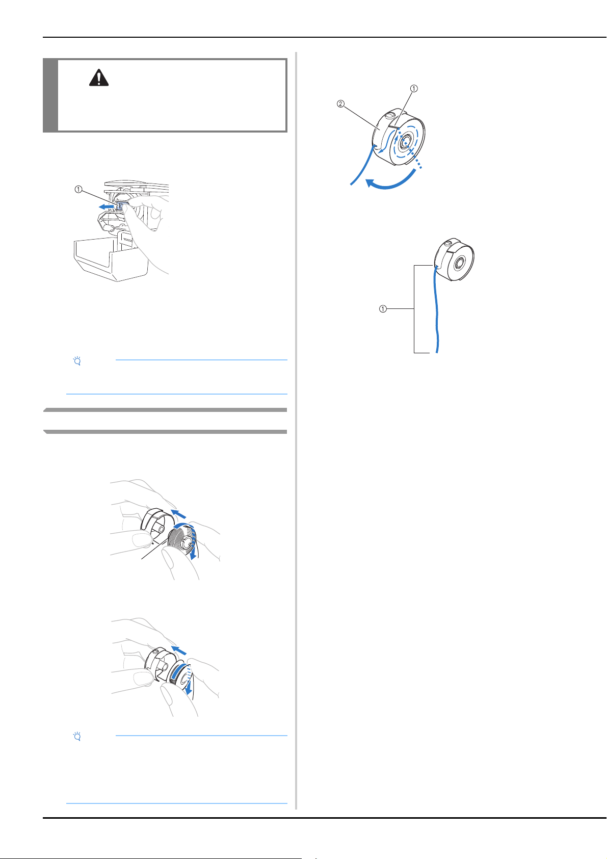
34
c
Grab the bobbin case latch, and remove the bobbin
case.
■ Oiling the machine
After removing the bobbin case, apply oil to the machine.
For details on oiling the machine, refer to “Oiling the
machine” on page 178.
Installing the bobbin
a
Insert the bobbin into the bobbin case.
• Prewound bobbin
1 Magnet Tip
• Metal bobbin (page 142)
b
Pass the thread through the thread slit and under the
tension-adjusting spring.
c
Pull the thread through the opening in the tension-
adjusting spring.
1 About 50 mm (2 inches).
• For details, refer to “Adjusting the tension of the
bobbin thread” on page 116.
CAUTION
• The thread picker can only be moved within a
certain range. Do not pull it with extreme
force.
1 Latch
Note
• Put a drop of oil onto the hook once a day before
use.
Note
• Check that the thread winds off the bobbin
clockwise as shown in the illustration. If the bobbin
is installed with the thread winding off in the
opposite direction, the embroidery will not be
stitched correctly.
a
1 Thread slit
2 Tension-adjusting
spring
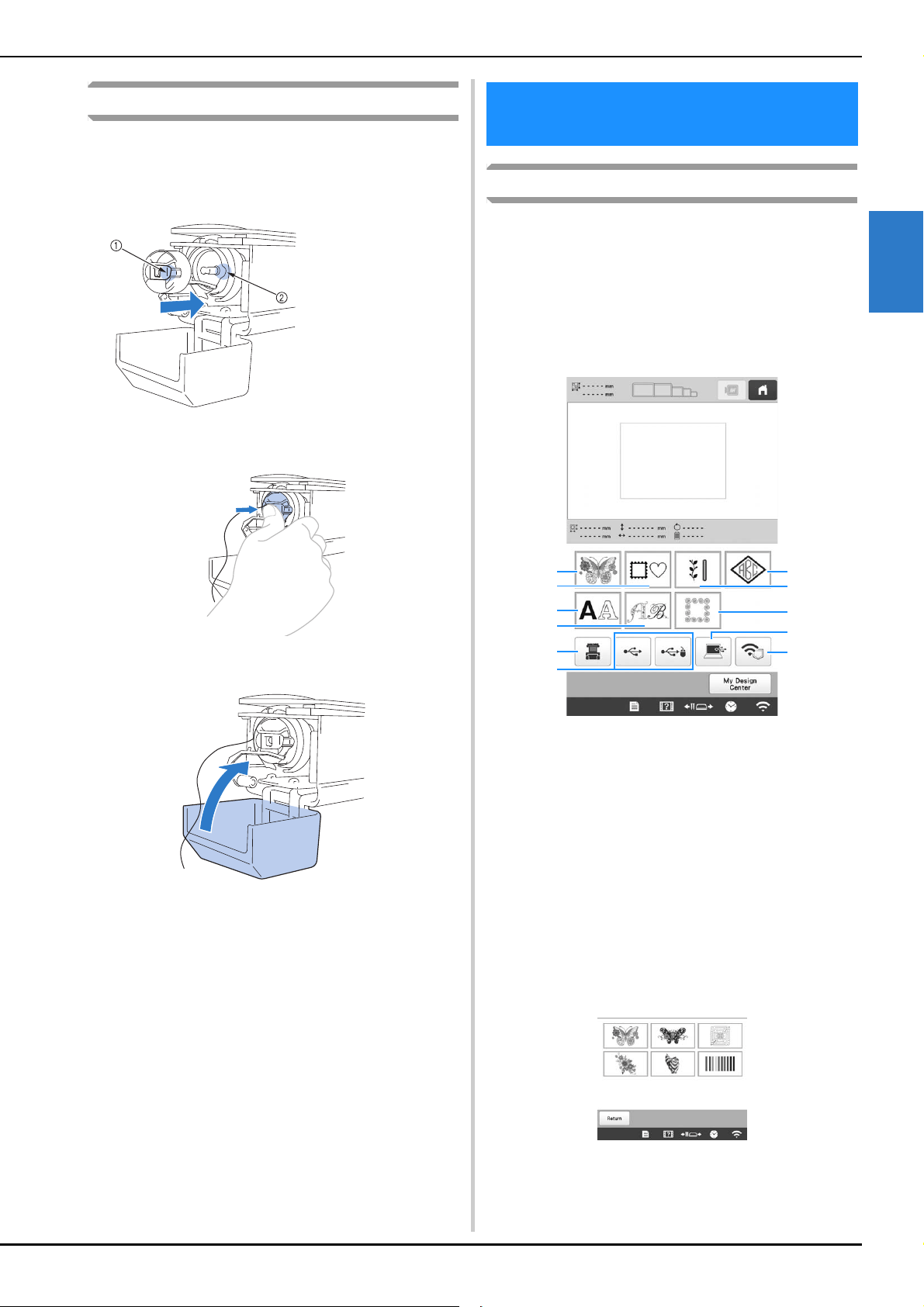
BASIC EMBROIDERY
35
2
Installing the bobbin case
a
Insert the bobbin case into the hook.
Insert the bobbin case while aligning the tab on the
bobbin case with the notch in the hook, as shown in the
illustration.
• Fully insert the bobbin case until it snaps into place.
b
Close the hook cover.
General pattern selection
The procedure for selecting a pattern differs depending on the
type of pattern; however, the general procedure for selecting a
pattern is described below.
a
In the pattern type selection screen, touch the key for
the desired category.
■ Pattern type selection screen
b
In the pattern category list screen, which appears next,
touch the desired pattern category to select it.
1 Tab
2 Notch
SELECTING AN EMBROIDERY
PATTERN
1 Embroidery patterns (page 36)
2 Frame patterns (page 37)
3 Character patterns (page 39)
4 Decorative alphabet patterns (page 41)
5 Monogram and frame patterns (page 38)
6 Utility embroidery patterns/Large buttonhole patterns
(page 37)
7 Quilting border patterns (page 105)
8 Patterns stored in the machine’s memory (page 130)
9 Patterns saved on USB media (page 130)
0 Patterns saved on a computer (page 130)
A Patterns to be transferred via the wireless network
(page 130)
3
2
1
5
A
0
4
6
7
8
9
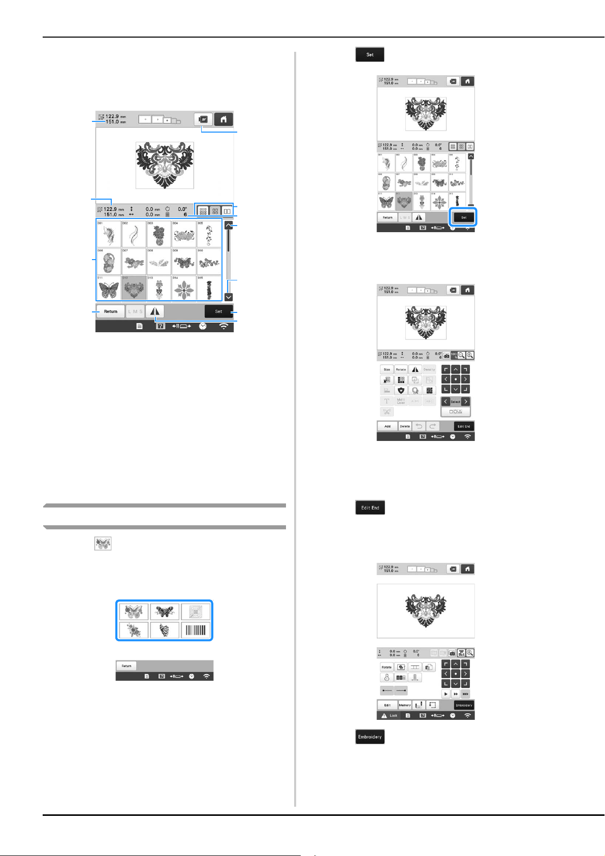
36
c
In the pattern list screen, which appears next, touch
the desired pattern to select it.
■ Pattern list screen
1 Size of the entire combined pattern
2 Size of the pattern being selected
3 Touch a pattern to display the information of the pattern.
4 Return to pattern category list screen to change
category.
5 Preview the embroidery image.
6 Select the size of pattern thumbnails from small, medium
and large sizes.
7 Number of thread color changes
8 Touch until the desired page is displayed if there is more
than one page.
9 Confirm the pattern, and move to the pattern editing
screen.
0 Flip the pattern being edited horizontally.
Embroidery patterns
a
Touch .
b
Select an embroidery pattern category.
The list of embroidery patterns appears.
c
Select an embroidery pattern.
The selected pattern appears in the pattern display
area.
d
Touch .
The pattern editing screen appears.
e
Edit the selected pattern. (page 44)
f
Hoop the stabilizer and fabric in the embroidery
frame. (page 61)
g
Attach the embroidery frame to the machine. (page 64)
h
Touch .
The embroidering settings screen appears.
i
Edit the entire pattern. (page 69)
j
Touch .
The embroidering screen appears.
7
3
8
8
0
5
1
4
2
9
6
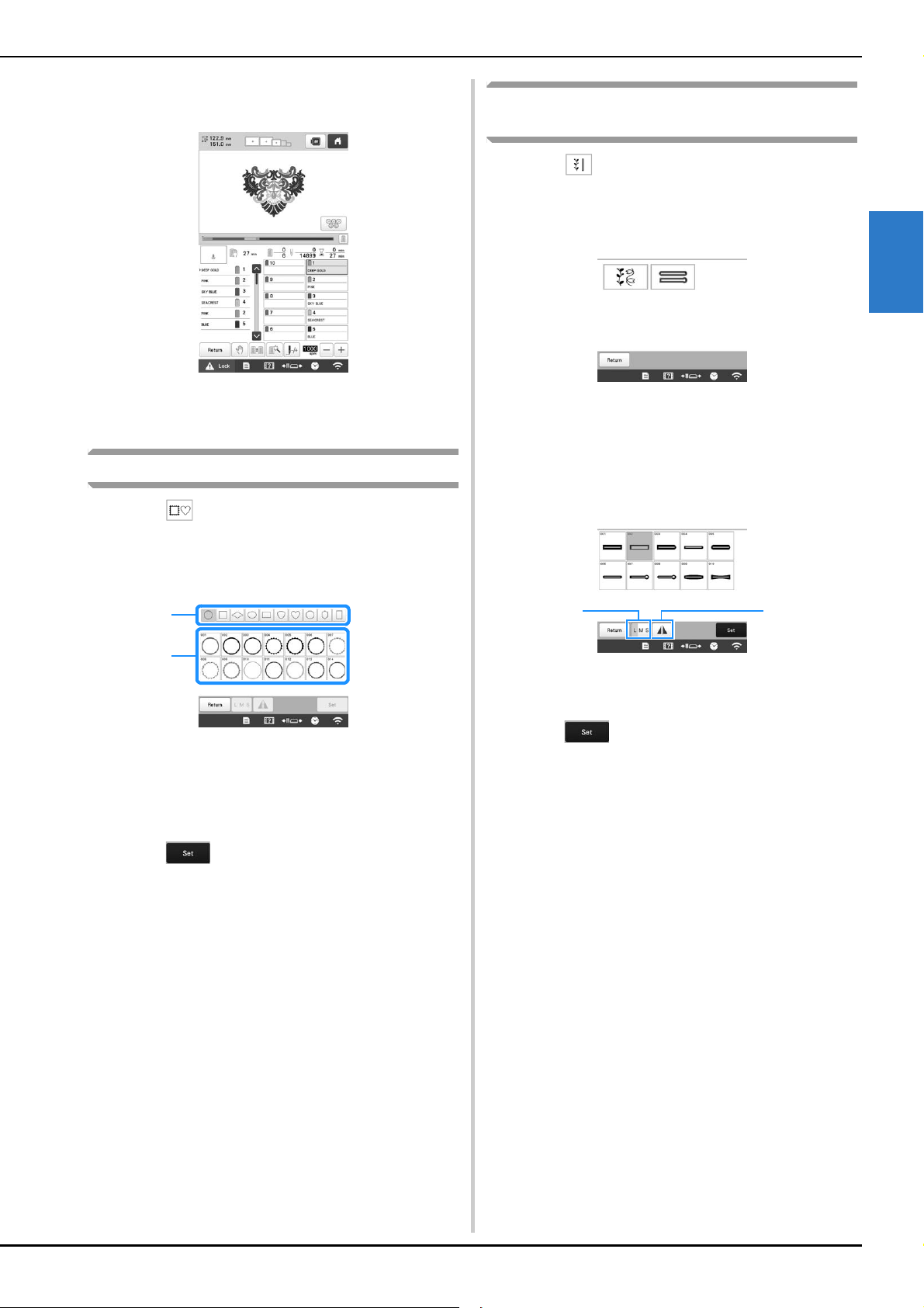
BASIC EMBROIDERY
37
2
k
Check the embroidering screen and thread the upper
threads. (page 81)
l
Start embroidering. (page 87)
Frame patterns
a
Touch .
b
From the upper tabs, select the desired frame shape.
Frame patterns appear below.
1 Frame shapes
2 Frame patterns
c
Touch the desired frame pattern.
The selected pattern appears in the pattern display
area.
d
Touch .
The pattern editing screen appears.
e
Follow the procedure from step e to l of
“Embroidery patterns” on page 36.
Utility embroidery patterns/Large
buttonhole patterns
a
Touch .
b
Select the desired category of the utility embroidery
patterns or the large buttonhole patterns.
The list of patterns of the selected category appears.
c
Select a pattern.
The selected pattern appears in the pattern display
area.
d
If necessary, edit the pattern.
1 Large buttonhole patterns can be selected from small,
medium and large sizes.
2 Flip the pattern horizontally.
e
Touch .
The pattern editing screen appears.
f
Follow the procedure from step e to l of
“Embroidery patterns” on page 36.
1
2
21
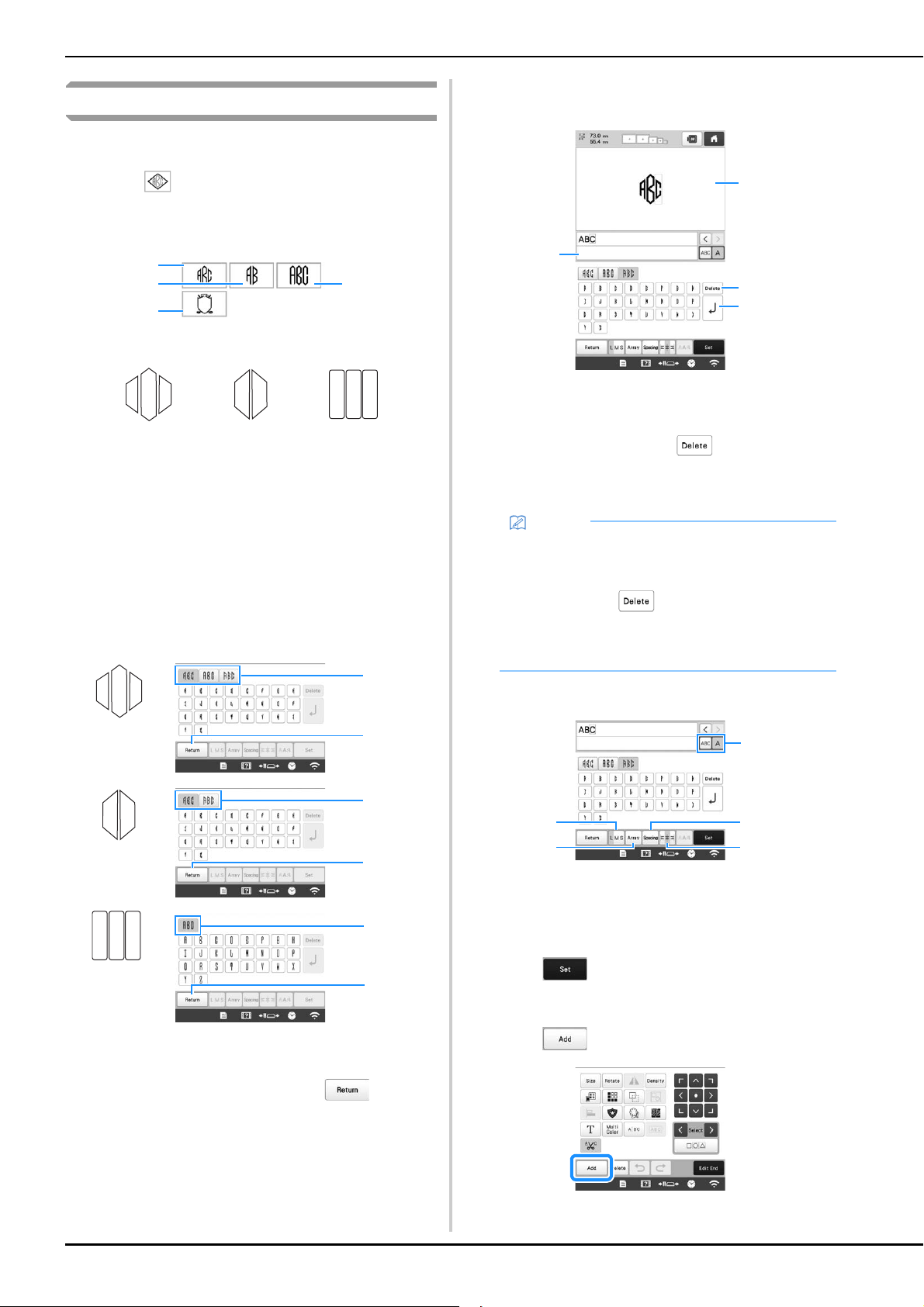
38
Monogram and frame designs
Monogram designs can be created by combining two or three
letters.
a
Touch .
b
Touch the button for the desired character style.
The text input screen appears.
• If 4 is selected, the frame pattern list appears. When
creating a pattern by combining letters with a frame, it
does not matter which of the two, the letters or the
frame, is selected first. The embroidering order
follows the order in which the parts of the monogram
are selected. For this example, we will select the
letters first.
c
Select the characters.
Touch the tabs to select different character shapes, and
then touch the key for one letter on each tab.
* Since the shapes of the letters are the same with this
design, there are no tabs to select.
1 Tabs
2 To change the character font, touch to return to
the design selection screen.
The selected characters appear in the text preview
area and the pattern display area.
1 Text preview area
2 Pattern display area
3 If the wrong character was selected or you wish to select
a different character, touch to delete the last
character selected, and then touch the desired
character.
4 Line feed key
d
If necessary, edit the characters. (page 40)
1 Select to edit all characters or one character.
2 Change the size of the characters.
3 Change the text arrangement.
4 Change the spacing of the character patterns.
5 Change the text alignment.
e
Touch .
The pattern editing screen appears.
Next, we will combine the letters with a frame.
f
Touch .
The pattern type selection screen appears.
1
2
3
*
4
1
2
3
2
1
2
1
2
1
Memo
• Depending on the design, there is a preset number
of letters; however, more than the preset number of
letters can be entered. If too many letters are
selected, touch to delete the letters.
• If desired, multiple letters can be selected to use
these characters in the same way as any other
character pattern without creating a monogram.
2
3
4
1
4
5
1
2
3
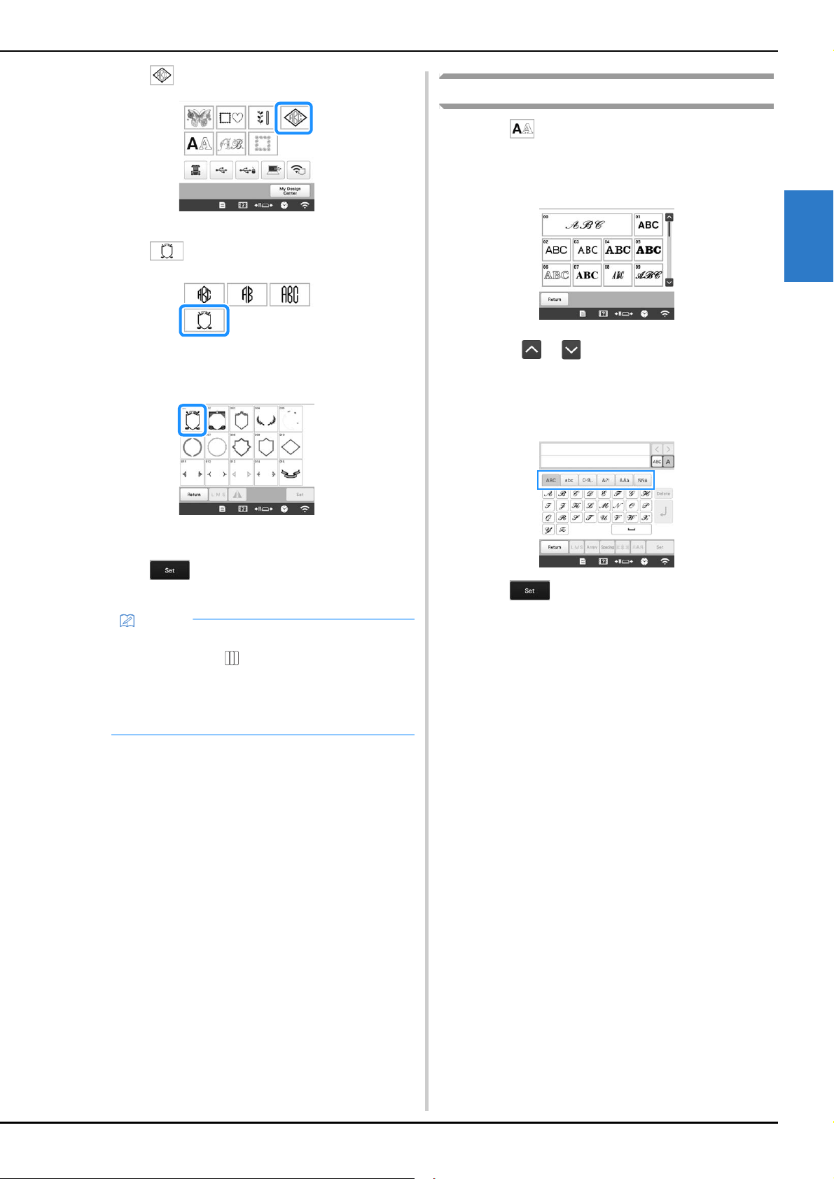
BASIC EMBROIDERY
39
2
g
Touch .
The design selection screen appears.
h
Touch .
The list of frame patterns appears.
i
Touch the desired pattern.
The selected frame pattern appears in the pattern
display area.
j
Touch .
The pattern editing screen appears.
k
Follow the procedure from step e to l of
“Embroidery patterns” on page 36.
Character patterns
a
Touch .
b
Touch the desired character font.
• Touch or for additional selections.
The text input screen appears.
c
Select the character category and then type in the text.
(page 40)
d
Touch .
The pattern editing screen appears.
e
Follow the procedure from step e to l of
“Embroidery patterns” on page 36.
Memo
• Due to size or shape, some frame patterns cannot
be used with the design.
• The frame patterns are just some of the patterns
that can be used. Character patterns other than the
3-letter monogram patterns can be used in the
combination.
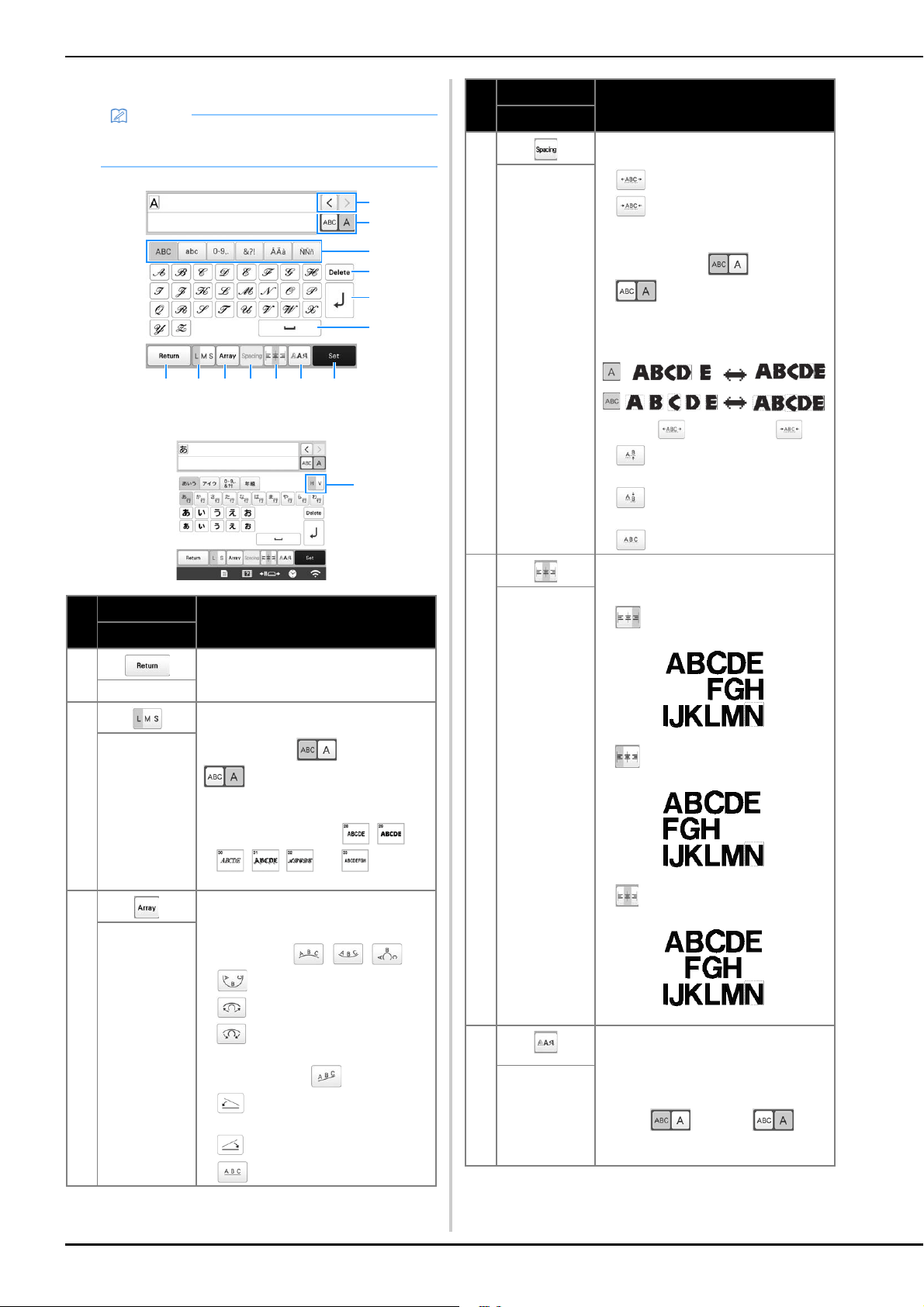
40
■ Character pattern input keys
Memo
• If a key display is grayed out, you cannot use that
function with the selected pattern.
No.
Display
Function
Key Name
1 Return to the previous screen.
Return key
2 Change the size of the character
patterns. To change the size of one
character, touch to display
and then select the character.
The size of the selected character is
changed.
• Size of the small fonts , ,
, , and cannot be
changed.
Size key
3 Change the layout of the character
patterns.
• To arrange the character patterns on
an arc, touch , , or
.
: Make the arc flatter.
: Make the arc rounder.
• To arrange the character patterns on
an incline, touch .
: Change the incline
counterclockwise.
: Change the incline clockwise.
• : Reset the layout.
Array key
B
A
0
9
4 51 2 3
8
6 7
C
D
4 Change the spacing of the character
patterns.
• : Increase the character spacing.
• : Decrease the character
spacing.
• To change the spacing after one
character, touch to display
and then select the character.
The spacing between the selected
character and the next character is
changed.
• : Move the one selected
character up.
• : Move the one selected
character down.
• : Reset the spacing.
Character
spacing key
5 Switch alignment. This function is
available when multiple lines of
characters are input.
• : Right alignment
• : Left alignment
• : Center alignment
Alignment key
6 Change the font of the characters.
Depending on the font that was selected,
it may not be possible to change the
font.
• To change the font of one character,
touch to display and
then select the character. The font of
the selected character is changed.
Font type key
No.
Display
Function
Key Name
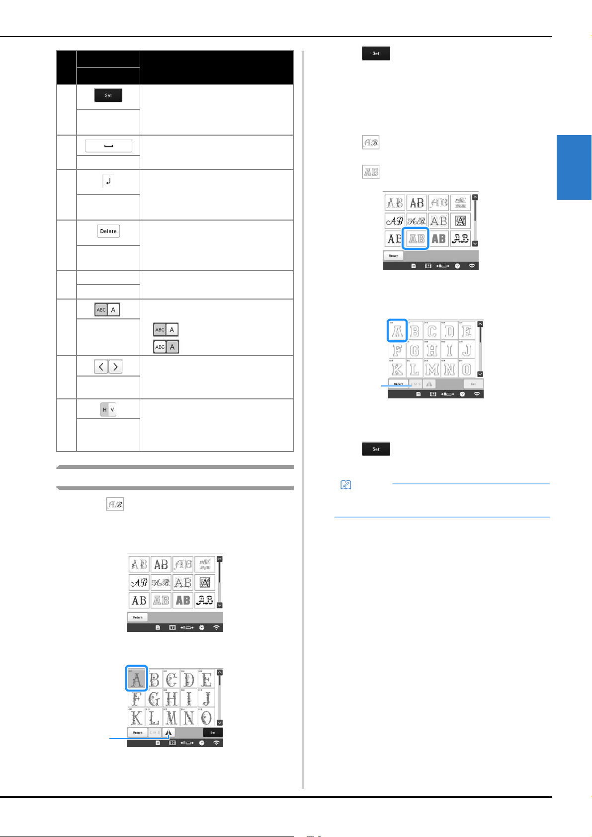
BASIC EMBROIDERY
41
2
Decorative alphabet patterns
a
Touch .
b
Touch the desired category.
c
Touch the desired pattern.
1 Flip the pattern horizontally.
The selected pattern appears in the pattern display
area.
d
Touch .
The pattern editing screen appears.
e
Follow the procedure from step e to l of
“Embroidery patterns” on page 36.
■ Appliqué alphabet
a
Touch .
b
Touch .
The list of appliqué alphabets appears.
c
Touch the desired pattern.
1 Change the character size.
The selected pattern appears in the pattern display
area.
d
Touch .
The pattern editing screen appears.
7 Apply the character pattern editing to go
to the editing screen.
Set key
8 Enter a space.
Space key
9 Make a new line.
Line feed key
0 Delete the character.
Delete key
A — Select the category of character.
Category keys
B Select to edit all characters or one
character.
• : Edit all characters.
• : Edit one character.
Select one/all
key
C Move the cursor and select a character.
Character
selection keys
D Switch between text written vertically
and horizontally. (Japanese font only)
Vertical/
horizontal text
key
No.
Display
Function
Key Name
1
Memo
• For details on embroidering appliqués, refer to
“Embroidering appliqué patterns” on page 100.
1
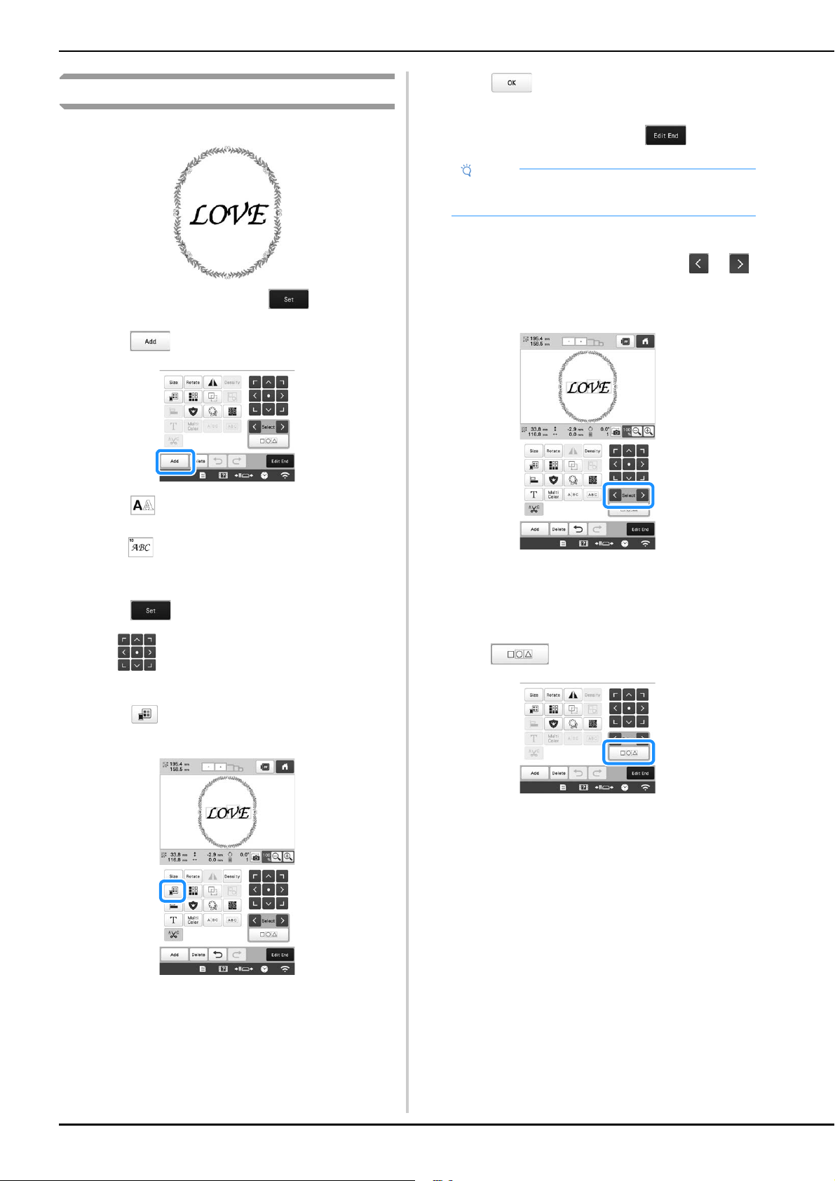
42
Combining patterns
Example:
a
Select a pattern and then touch .
b
Touch .
c
Touch .
d
Select and enter “LOVE”.
The characters you enter will be displayed in the
center of the embroidery pattern area.
e
Touch .
f
Use to move the characters.
*
Characters can also be moved by directly dragging them
with your finger or the touch pen.
g
Touch to change the color of the characters.
(page 54)
h
Touch .
i
When all editing is finished, touch .
■ Selecting the pattern to be edited
If multiple patterns have been combined, use or
to select the pattern to be edited. Patterns can also be
selected by directly touching the screen with your finger
or touch pen.
■ Selecting multiple patterns at the same time
Multiple patterns can easily be edited, for example, when
moving patterns that are combined, if they are all selected
together.
a
Touch .
The multiple selection screen appears.
Note
• Combined patterns will be embroidered in the
order they were entered.
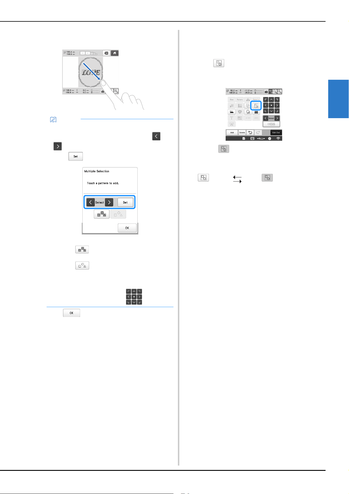
BASIC EMBROIDERY
43
2
b
Select the multiple patterns by dragging your finger in
the screen to create a box around the desired patterns.
c
Touch to return to the pattern editing screen.
• The multiple selected patterns are surrounded with a
red box.
■ Grouping multiple selected patterns
If the multiple patterns selected in “Selecting multiple
patterns at the same time” on page 42 are grouped, they
can be edited as a single pattern.
a
Touch .
The selected patterns are grouped.
• Touch to ungroup the patterns. If there are
multiple grouped patterns, the selected pattern group
is ungrouped.
Memo
• Multiple patterns can be selected or deselected
from the multiple selection screen. Touch or
to check the patterns to be selected, and then
touch .
The selected pattern is surrounded with a red box.
- Touch to select all patterns in the pattern
display area.
- Touch to deselect all selected patterns.
- The patterns can also be selected by touching
them in the screen.
- While the multiple selection screen is displayed,
patterns can be moved with .
Ungrouped Grouped
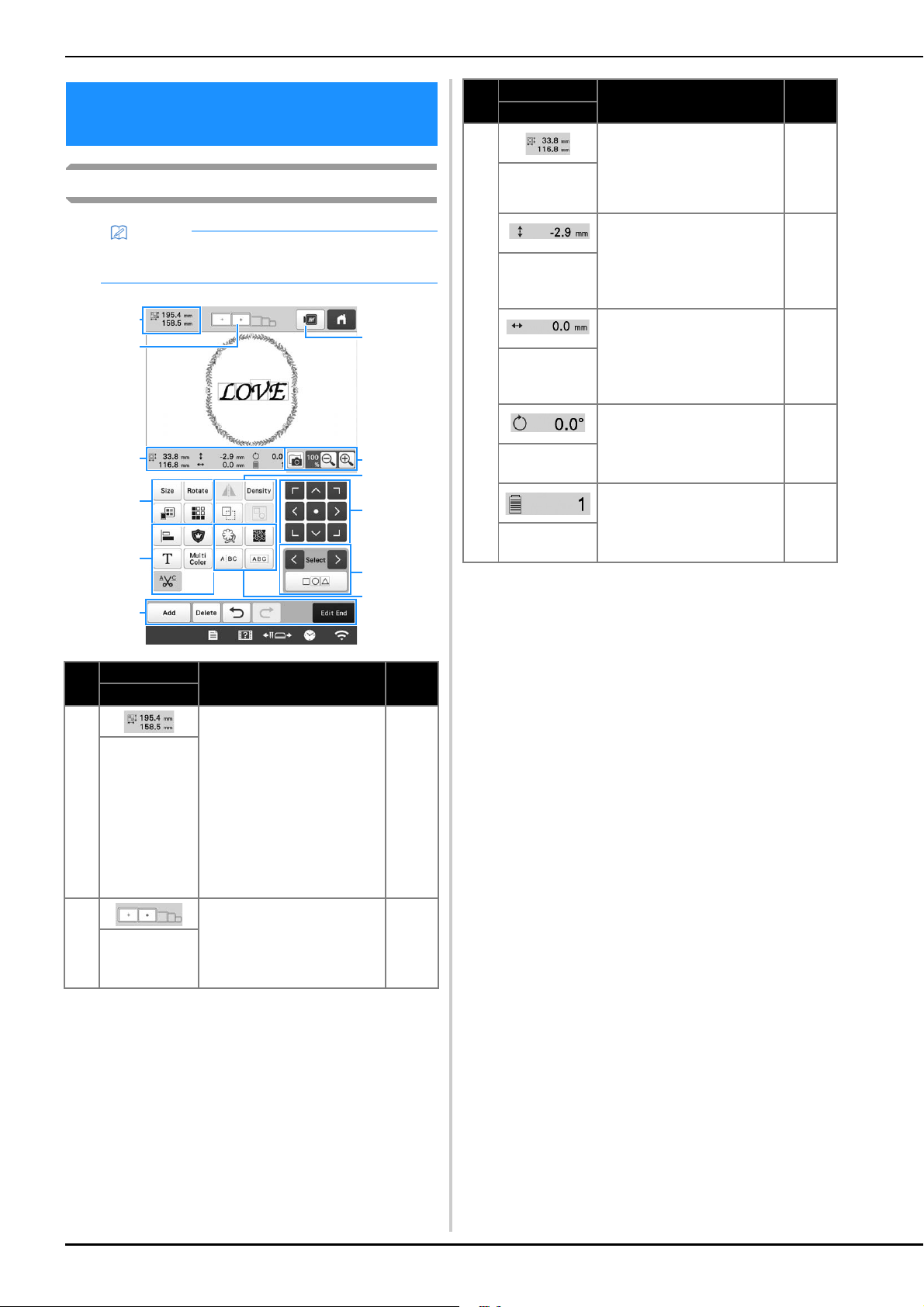
44
Understanding the pattern editing screen
EDITING THE EMBROIDERY
PATTERN
Memo
• If a key display is grayed out, you cannot use that
function with the selected pattern.
No.
Display
Function Page
Key Name
1
Shows the size of the
embroidery pattern currently
displayed in the pattern
display area. The top value
shows the height and the
bottom value shows the
width. If the embroidery
pattern consists of multiple
patterns that have been
combined, the size will
include all patterns.
—
Pattern size
2
Shows the sizes of
embroidery frames that can
be used to embroider the
pattern currently displayed
in the pattern display area.
61
Embroidery
frame
indicators
2
0
A
7
1
9
B
3
4
5
6
8
3
Shows the size of the pattern
being edited. The top value
shows the height and the
bottom value shows the
width.
—
Size
Shows the vertical distance
that the pattern being edited
is moved.
—
Distance from
center
(vertical)
Shows the horizontal
distance that the pattern
being edited is moved.
—
Distance from
center
(horizontal)
Shows the rotation angle that
the pattern being edited is
rotated.
—
Rotation angle
Shows the total number of
thread colors for the pattern
that is being edited.
—
Number of
thread colors
No.
Display
Function Page
Key Name
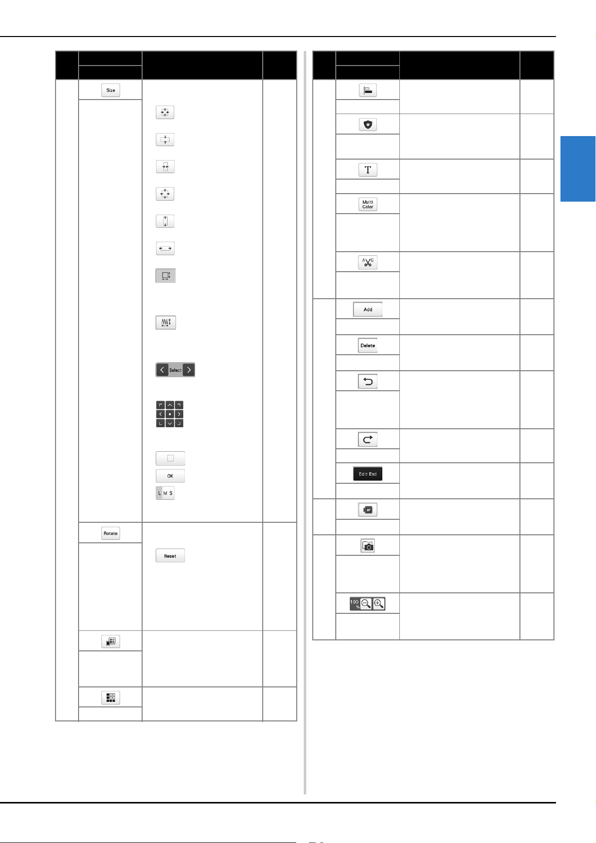
BASIC EMBROIDERY
45
2
4
Display the pattern sizing
window.
• : Decrease the pattern
proportionately.
• : Decrease the pattern
vertically.
• : Decrease the pattern
horizontally.
• : Enlarge the pattern
proportionately.
• : Stretch the pattern
vertically.
• : Stretch the pattern
horizontally.
• : Change the pattern
size while maintaining the
number of stitches. (normal
resizing mode)
• : Change the pattern
size while maintaining the
thread density. (stitch
recalculator mode)
• : Select the
pattern that you want to
change.
• : Move the pattern in
the direction shown by the
arrow.
• : Reset the size.
• : Close this screen.
• : Change the size of the
pattern (character patterns
only).
—
Size key
Display the pattern rotating
window.
• : Reset the angle.
Rotate the pattern using the
rotate keys or by dragging
the red point at the corner of
the pattern. You can also use
the move keys during the
rotation process.
—
Rotate key
Change the color of the
pattern.
54
Change
thread color
key
Make and edit the repeated
pattern.
49
Border key
No.
Display
Function Page
Key Name
5
Arrange multiple patterns on
a line.
49
Alignment key
Change the pattern being
edited into an appliqué
pattern.
101
Embroidery
appliqué key
Edit characters. 46
Letter Edit key
Enable the thread color of
each character in a character
pattern to be changed; can
only be used when a
character is selected.
54
Multi color
key
Automatically trim any
excess thread jumps within
the letters of character
pattern.
47
Thread trim
setting key
6
Add a pattern. If touched, the
pattern type selection screen
appears.
42
Add key
Deletes the pattern. If
touched, the pattern being
edited is deleted.
—
Delete key
Undo the last operation that
was performed and return to
the previous state. Each
touch of this key will undo
one operation.
—
Undo key
Redo the operation that was
undone.
—
Redo key
Finish editing and continue
to the embroidering settings
screen.
—
Edit end key
7
Display an image of the
pattern so that it can be
previewed.
—
Preview key
8
Scan the fabric in the
embroidery frame with the
built-in camera to display it
as the background of the
pattern.
72
Fabric scan
key
Select from 100%, 125%,
150% or 200% to adjust
how the pattern being edited
is displayed.
—
Enlarge key
No.
Display
Function Page
Key Name
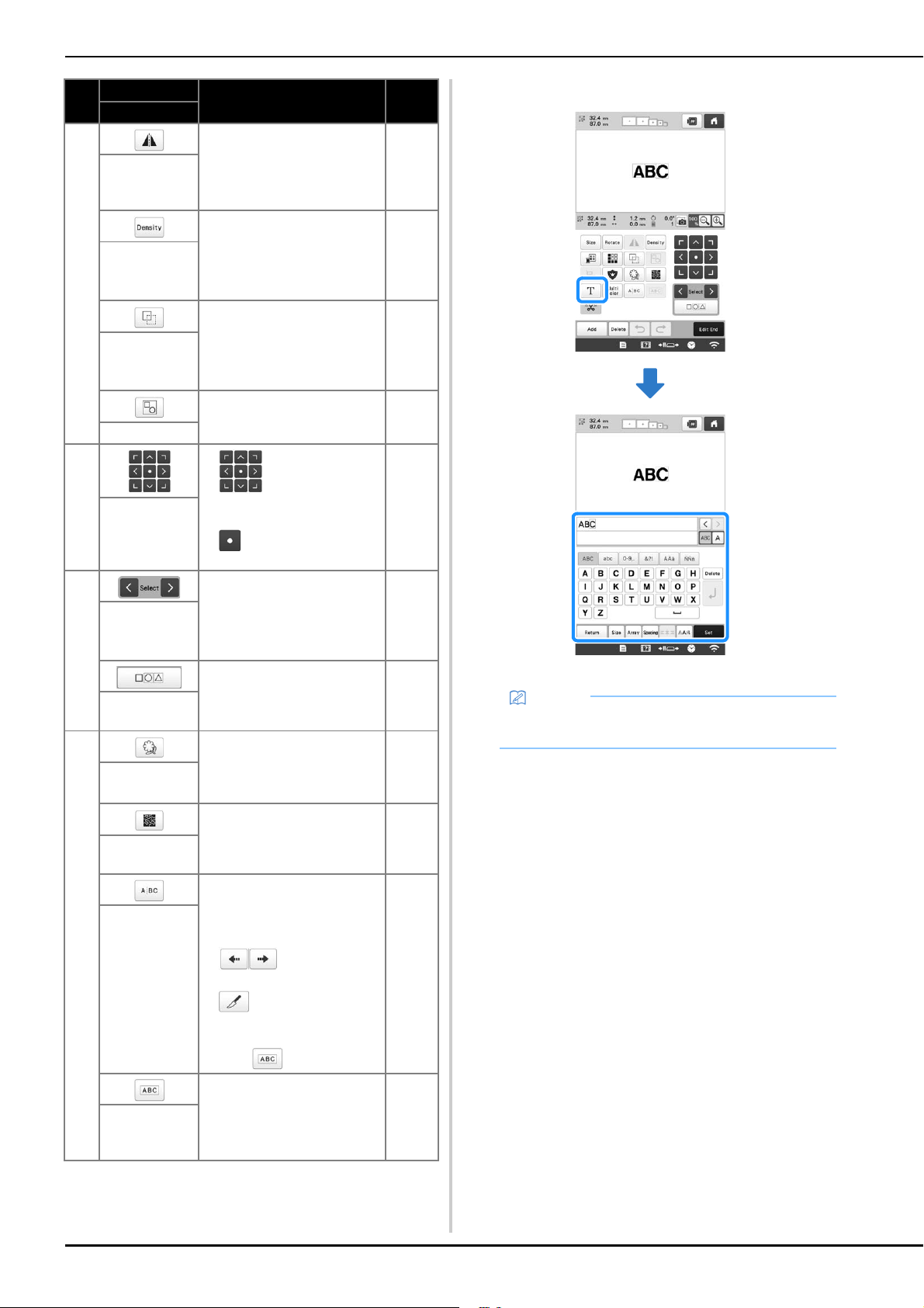
46
■ Editing letters
For details on input keys, refer to page 40.
9
Change the pattern to a
horizontal mirror image.
—
Horizontal
mirror image
key
Change thread density for
some character and frame
patterns. Other patterns'
density can be adjusted in
the stitch recalculator mode.
48
Density key
Duplicate the pattern.
The duplicated pattern will
be positioned slightly lower
and to the right from the
original pattern.
—
Duplicate key
Group selected multiple
patterns.
43
Group key
0
• : Move the pattern in
the direction shown by the
arrow.
• : Move to the center of
the embroidering area.
42
Positioning
keys
A
Selects the pattern that is
being edited when the
embroidery pattern consists
of multiple patterns that have
been combined.
43
Pattern
selection keys
Choose multiple patterns to
be edited at the same time.
42
Multiple
selection key
B
Extract the outline of the
pattern. The extracted
pattern can be used with My
Design Center.
170
Outline key
Create stippling or echo
quilting around the pattern.
104
Stippling/Echo
Quilting key
Separate the continuous
character patterns to adjust
the spacing or edit separately
afterwards.
• : Select where the
patterns is to be separated.
• : Separate the pattern.
A separated character
pattern can be combined by
using .
—
Text dividing
key
Combine the selected
character patterns.
48
Text
combining
key
No.
Display
Function Page
Key Name
Memo
• To edit character patterns with multiple lines in the
edit screen, ungroup the pattern. (page 43)

BASIC EMBROIDERY
47
2
Changing the size and the density of the
pattern
If is selected, you can change the pattern size while
maintaining the thread density. The machine recalculates the
stitch density automatically. With this function, the pattern
can be enlarged or reduced at a larger ratio than with normal
pattern resizing.
a
Select or in the size window.
*
: Change the pattern size while maintaining the
number of stitches. The thread density for the pattern
increases or decreases.
*
: Change the pattern size while maintaining the
thread density. After the pattern size is changed, the thread
density can be changed. The number of stitches is
recalculated depending on the pattern size.
b
When you select in step a, the message to reset
the pattern to its original size, angle and position will
appear. Touch .
c
Touch each key to change the pattern size, if desired.
d
Touch .
Trimming the threads between characters
If the machine is set to trim the threads between the
characters, the jump stitches between the characters are
reduced and any other necessary procedures after
embroidering are reduced. However, the embroidering time
will increase if the threads are trimmed between each of the
characters.
a
Touch so that it changes to .
• Each touch of the key turns the setting either on or off.
Note
• This function cannot be used with character
patterns, frame patterns, repeated patterns or large
buttonhole patterns.
• Patterns with a large number of stitches (100,001
or more) cannot be resized while maintaining a
thread density.
Memo
• Depending on the pattern, the size of the pattern
increases up to 200% or reduces to 60%.
• You can also change the size by dragging the red
point around the pattern.
Memo
• When you select in step a, touch ,
and then change the thread density.
Threads are
not trimmed.
Threads are
trimmed.
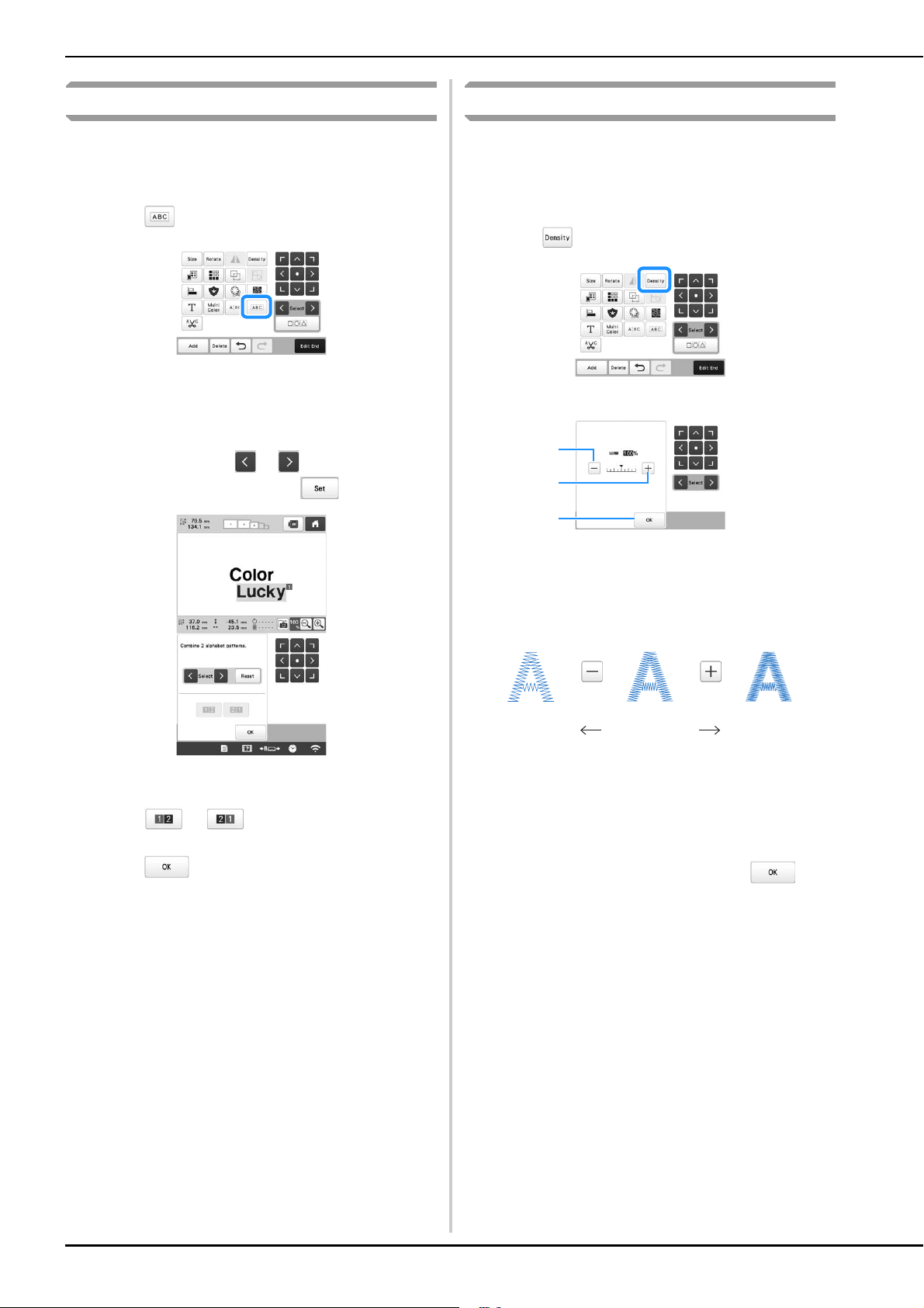
48
Combining the separated character patterns
Two separated lines of character patterns can be combined.
The characters can be aligned to the specified order. You
cannot combine the lines of character patterns if the text
contains a line feed using the Line Feed function.
a
Touch .
b
Select the group of character patterns that you want to
combine.
• The selected character is assigned as Number [1].
• You can select the patterns by touching them on the
screen, or touching or to check the patterns
to be selected, and then touch .
Numbers [1] and [2] are assigned temporarily to the
patterns.
c
Touch or to choose the order of the 2
patterns.
d
Touch to return to the previous screen.
Changing the thread density
The thread density for some character and frame patterns can
be changed. Other patterns' density can be adjusted in the
stitch recalculator mode. (page 47)
A setting between 80% and 120% in 5% increments can be
specified.
a
Touch .
The screen shown below appears.
1 Make the pattern less dense.
2 Make the pattern more dense.
3 Close this screen.
■ Selects a less/more thread density
a
Touch the keys to select the desired thread density.
Each touch of a key slightly increases or decreases the
thread density.
• To return to the original thread density (standard),
select [100%].
b
After making the desired changes, touch .
Less Standard More
3
1
2
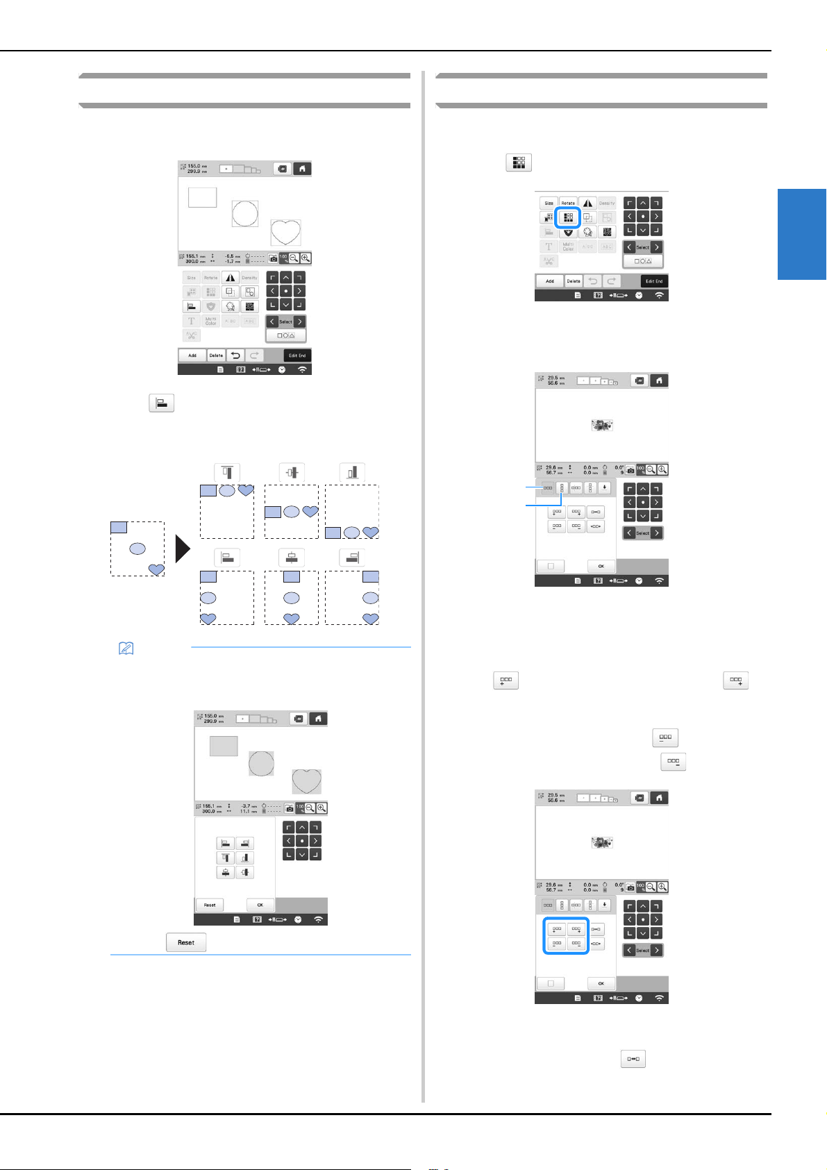
BASIC EMBROIDERY
49
2
Aligning the embroidery patterns
a
Select patterns that you want to align. (page 42)
b
Touch , and then select the key for the desired
alignment.
Example
Designing repeated patterns
Using the border function, you can create an arrangement
using repeated patterns.
a
Touch .
b
Select the direction in which the pattern will be
repeated.
1 Horizontal direction
2 Vertical direction
The pattern direction indicator will change
depending on the direction selected.
c
Use to repeat the pattern on the left and to
repeat the pattern on the right.
• To delete the left pattern, touch .
• To delete the right pattern, touch .
d
Adjust the spacing of the repeated pattern.
• To widen spacing, touch .
Memo
• You can select desired multiple patterns by directly
touching each pattern on this screen.
• Touch to reset the alignment.
2
1
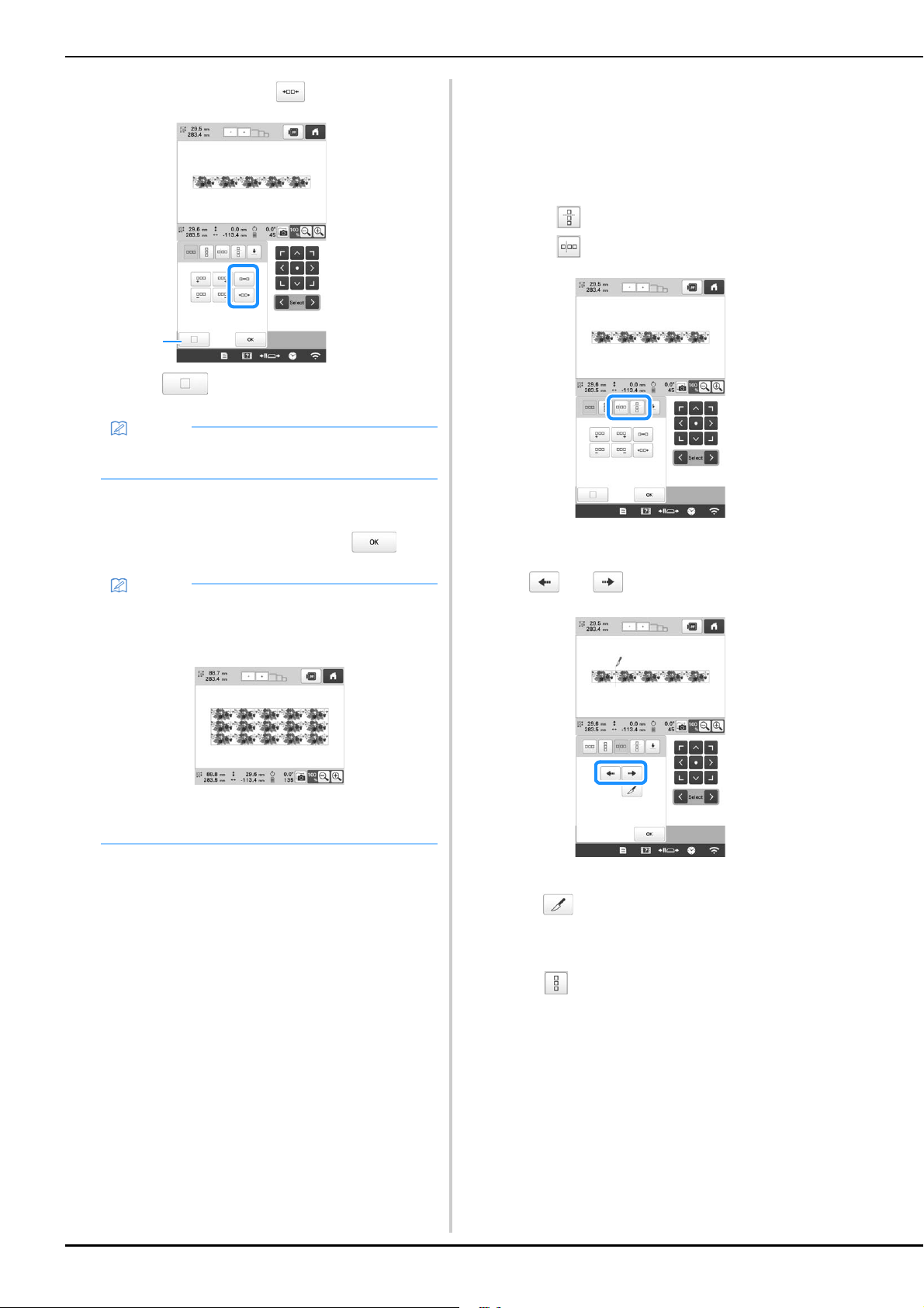
50
• To tighten spacing, touch .
1 Touch to change a repeated pattern back to
one single pattern.
e
Complete repeated patterns by repeating steps b
through
d.
f
After making the desired changes, touch .
■ Repeating one element of a repeated pattern
By using the Cut function, you can select one element of a
repeated pattern and repeat only that single element. This
function allows you to design complex repeated patterns.
a
Choose the direction in which the repeated pattern will
be cut.
• Touch to cut horizontally.
• Touch to cut vertically.
The pattern direction indicator will change
depending on the direction selected.
b
Use and to select the cut line.
The cut line will move.
c
Touch .
The repeated pattern will be divided into separate
elements.
d
Touch .
Memo
• You can only adjust the spacing of patterns
included in the red frame.
Memo
• When there are two or more patterns, all patterns
will be grouped together as one pattern in the red
frame.
• When changing the direction in which the pattern
will be repeated, all of the patterns in the red frame
will automatically be grouped as one repeating unit.
1
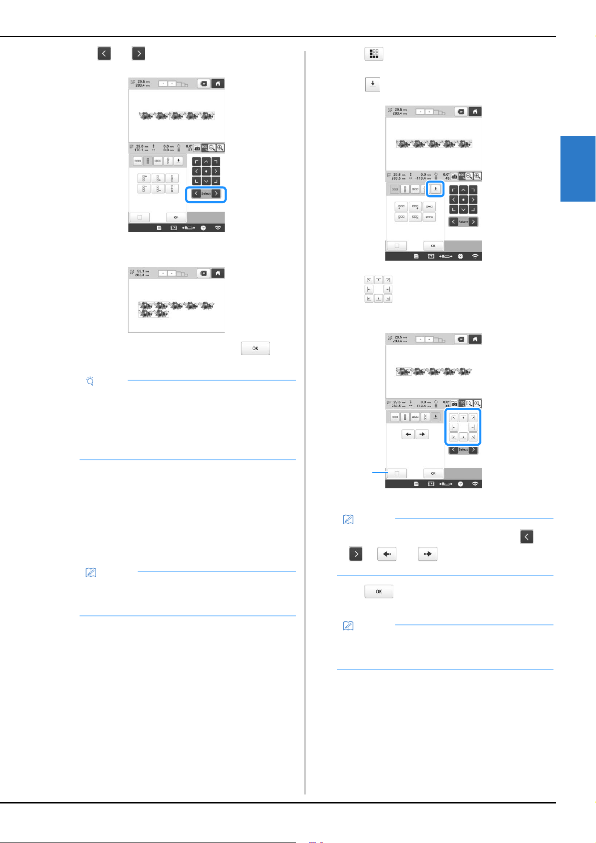
BASIC EMBROIDERY
51
2
e
Use and to select the element to repeat.
f
Repeat the selected element.
g
After making the desired changes, touch .
■ Assigning thread marks
By embroidering thread marks, you can easily align
patterns when embroidering a series. When embroidery is
finished on a pattern, a thread mark in the shape of an
arrow will be embroidered using the final thread. When
embroidering a series of patterns, use the point of this
arrow for positioning the following designs to be
embroidered.
a
Touch .
b
Touch .
c
Touch to select the thread mark to be
embroidered.
1 Touch to cancel thread mark setting.
d
Touch .
Note
• Once you have cut a repeated pattern into separate
elements, you cannot return to the original
repeated pattern.
• Each element can be edited separately in the edit
screen. Refer to “Selecting the pattern to be
edited” on page 42.
Memo
• When repeatedly embroidering individual patterns,
thread marks can be embroidered around the
perimeter of the pattern only.
Memo
• When there are two or more elements, use and
or and to select a pattern that you
want to assign a thread mark(s) to.
Memo
• If the combined border pattern is rotated in the
embroidering settings screen, the thread mark will
be removed.
1
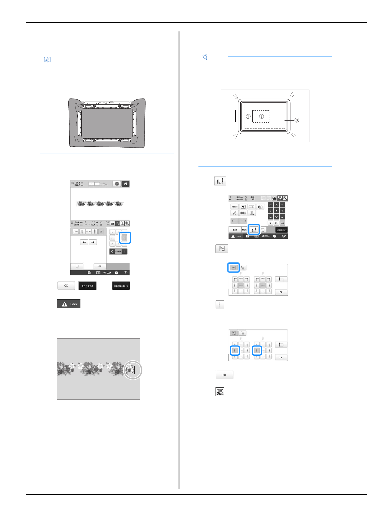
52
■ Embroidering the pattern repeatedly
After creating the repeated pattern, rehoop the embroidery
frame and keep embroidering for the next pattern.
a
Create the repeated pattern with the thread mark at
the center of the end of the pattern. (page 51)
b
Touch , , then .
c
Touch , and then press the “Start/Stop”
button to start embroidering.
When embroidering is finished, the thread mark is
embroidered with the last thread color.
d
Remove the embroidery frame.
e
Rehoop the fabric in the embroidery frame.
f
Attach the embroidery frame to the machine, and then
touch in the embroidering settings screen.
g
Touch .
h
Touch to set the starting point to the left side of
the pattern.
i
Touch .
j
Touch .
Memo
• Using the optional magnetic sash frame, the fabric
can be easily rehooped without removing the frame
from the machine. For details, refer to the manual
included with magnetic sash frame.
Note
• Adjust the position of the fabric so that the
embroidering area for the next pattern is within the
embroidering area of the embroidery sheet.
1 Pattern embroidered first
2 Position of pattern to be embroidered next
3 Embroidering area of embroidery sheet
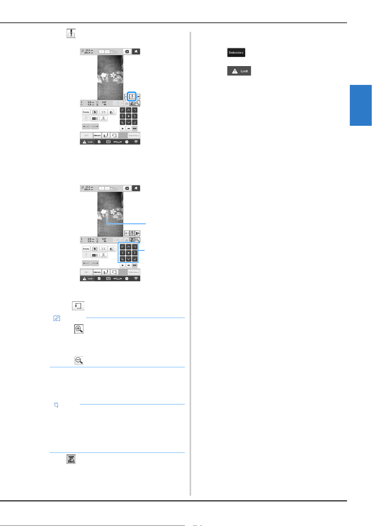
BASIC EMBROIDERY
53
2
k
Touch to display the needle drop point.
l
Touch the positioning keys to move the embroidery
frame until the thread mark on the fabric is aligned on
the needle drop point in the camera view window.
1 Thread mark on the fabric
2 Positioning keys
• Touch to check the embroidering position.
m
If the pattern position cannot be aligned using the
positioning keys, rehoop the fabric, and then try again
to align the position with the positioning keys.
n
Touch to return to the previous screen.
o
Remove the thread mark.
p
Touch .
q
Touch , and then press the “Start/Stop”
button to start embroidering.
Memo
• Touch to enlarge the camera view. By
enlarging the camera view, you can make a close
adjustment for the needle drop position moving the
embroidery frame little by little.
Touch to return to the normal camera image.
Note
• After you have aligned the position of the combined
border pattern, do not rotate the pattern in the
embroidering settings screen. If the pattern is
rotated in the embroidering settings screen after
alignment, the pattern will not be properly aligned
with the thread mark or starting point.
2
1
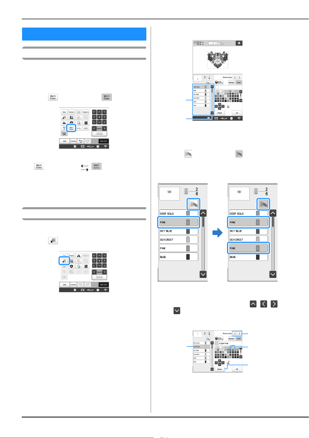
54
Specifying multi-color text
The alphabet pattern characters selected on page 39 are set to
black. The color of the characters can be changed using the
change thread color key; however, to change the color of
individual characters, touch the Multi Color key to turn it on,
and then specify the color for each character.
a
Touch so that it changes to .
• Each touch of the key turns the setting either on or off.
• For details on changing the thread color, refer to
“Changing the colors of the pattern” below.
Changing the colors of the pattern
The colors of the pattern can be changed and previewed on
the screen.
a
Touch .
The change thread color screen appears.
b
From the thread color sequence display, select the
thread color whose color is to be changed.
• If the desired thread color is not displayed, use the
scroll bar on the right side to display it.
The selected thread color image appears.
1 Selected thread color image
2 Scroll bar
• To combine the same thread color when it is used
more than once, select the thread color, and then
touch . The key changes to , and all thread
colors in the thread color sequence display that are
the same as the one that was selected are highlighted
in blue.
• The part of the pattern whose thread color is to be
changed can be directly selected in the pattern.
c
Select the thread brand, and then touch , ,
or , or directly touch the desired color, to select
the new color from the color palette.
1 Select the thread brand.
2 The color in the box is the color that is selected.
3 Return to the original color.
4 Displays the name of the selected thread color.
EDITING COLORS
Multi-color text
turned off
Multi-color text
turned on
1
2
4
2
1
3
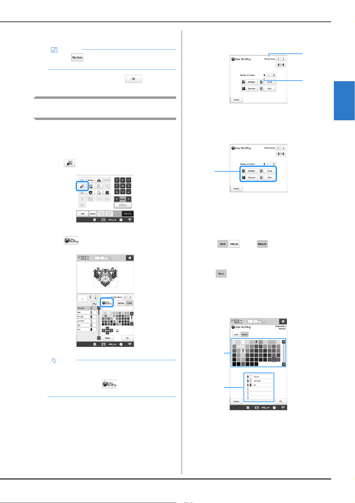
BASIC EMBROIDERY
55
2
In the pattern display area, the color of the selected
part of the pattern is changed.
d
After changing the colors, touch .
Find new color schemes with the color
shuffling function
With the Color Shuffling function, the machine suggests new
color schemes for the embroidery pattern that you have
selected. After you select the desired effect from one of the
four available color schemes ([Random], [Vivid], [Gradient]
and [Soft]) the sample for the selected effect is displayed.
a
Touch .
The change thread color screen appears.
b
Touch .
c
Select the thread brand for colors and the number of
colors you want to create the pattern with.
1 Thread brand for colors
2 Number of colors to be used
d
Select the desired effect.
1 Effects for schemes
If you select [Random] or [Gradient], the color
specifying screen will appear.
If you select [Vivid] or [Soft], there is no color
specifying screen. Proceed to step g.
e
Touch to set and specify the thread
color to use in the effect.
* If you don’t need to specify the thread color, just set
to .
[Manual] setting for [Random]
You can select up to 6 colors to be used in the [Random]
effect. The effect will be created using the selected colors.
1 Select colors from the palette.
2 Selected colors are listed.
Memo
• Touch to specify a thread color by entering
its number.
Note
• This function may not be available depending on
the pattern you select (ex. a bordered pattern,
licensed pattern). If is grayed out, select
another pattern.
1
2
1
1
2
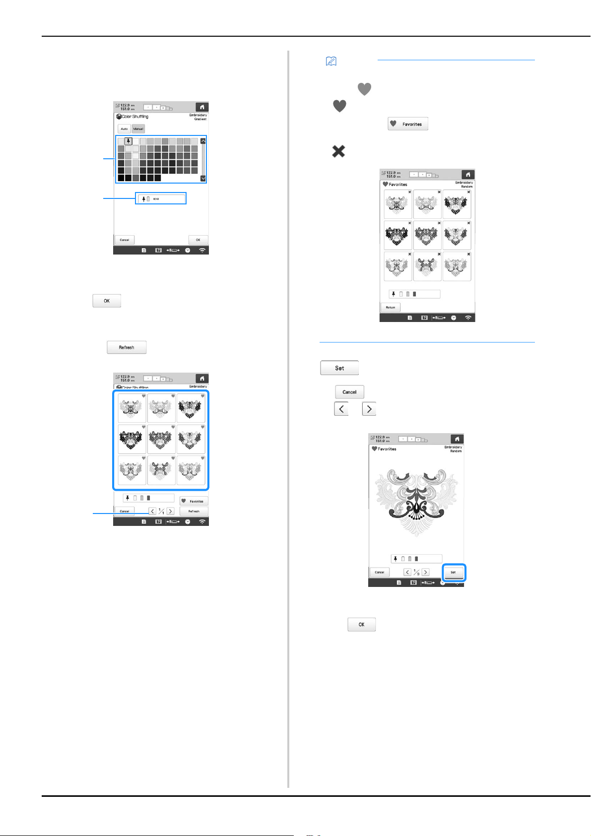
56
[Manual] setting for [Gradient]
You can select one color to be used in the [Gradient] effect.
The effect will be created with the color you select.
1 Select a color from the palette.
2 Selected color is displayed.
f
Touch .
g
Select the color scheme from samples.
* Touch to add the new schemes.
1 Touch to review the previous schemes.
h
Check the displayed color scheme, and then touch
.
* : Return to the previous screen.
* or : Display the other color schemes.
The change thread color screen will appear.
i
Touch to display to the pattern editing screen.
1
2
1
Memo
• To temporarily register your favorite schemes,
touch (to release your favorite schemes, touch
again). 9 color schemes can be saved on the
page*. Touch to check the registered
favorite schemes. To cancel the registration, touch
.
* Maximum 20 pages of schemes can be reviewed.
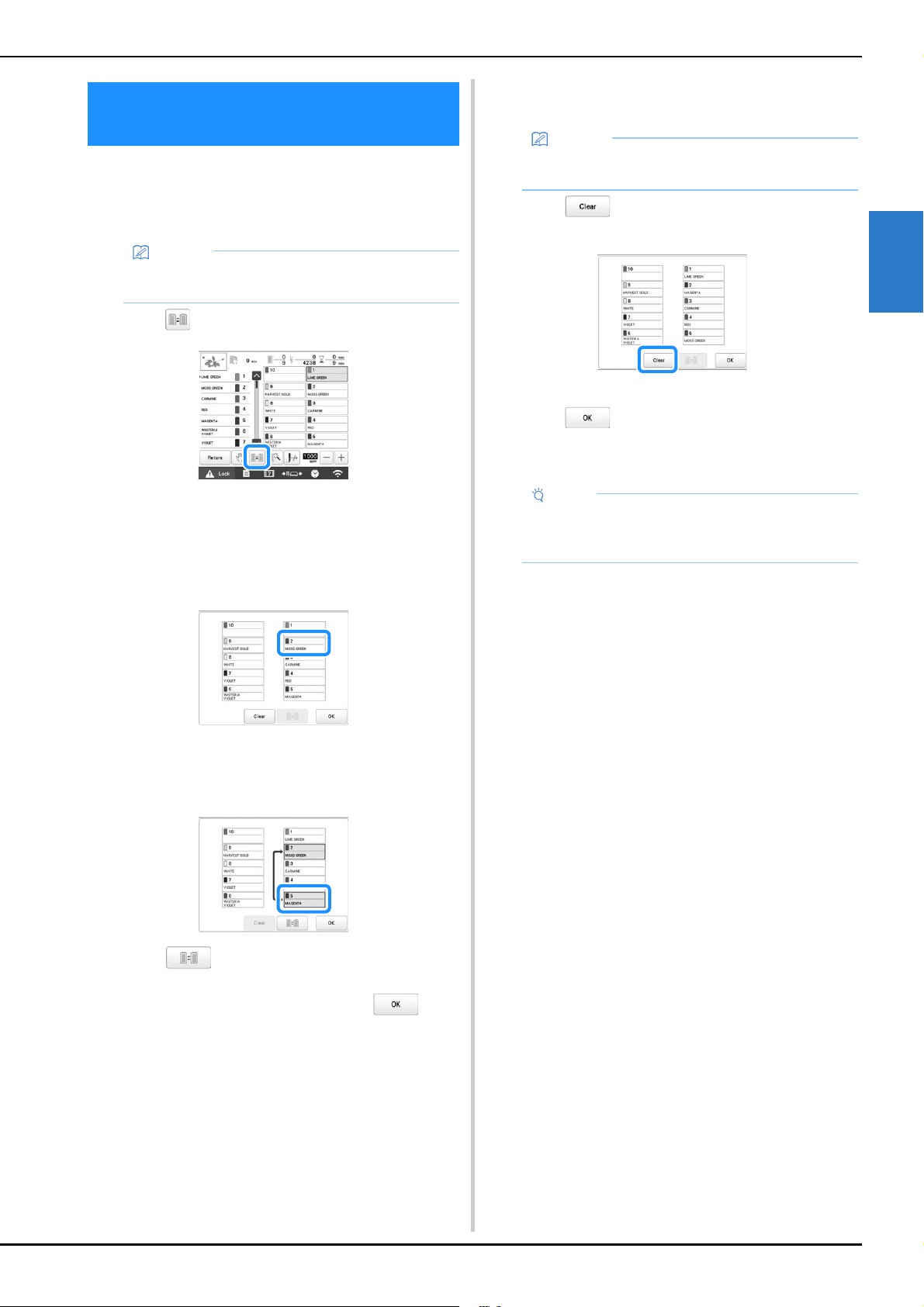
BASIC EMBROIDERY
57
2
If a thread color on the spool stand is different than the
needle position thread color on the screen, the thread
colors on the screen can be switched to match the spool
stand thread color position.
a
Touch in the embroidering screen.
The spool selection screen appears.
b
Touch the number of the first needle bar that will be
switched.
• To cancel the selection, touch the same needle
number again.
c
Touch the number of the other needle bar that will be
switched. The two needle numbers are connected with
an arrow.
d
Touch to switch the two thread colors.
e
After making the desired changes, touch .
■ To cancel the thread color settings for all
previously stitched design
a
Touch .
The thread color setting is canceled.
b
Touch .
Thread colors are assigned by the machine again,
regardless of the previous spool setting.
SWITCHING THE THREAD COLORS
ON THE SCREEN
Memo
• This function is not available when you set [Manual
Color Sequence] to [ON] in settings screen.
Memo
• The color settings will be completely canceled even
if the machine is in the middle of the embroidery.
Note
• This function will not clear anchor settings of any of
the needles which have been assigned a thread
color. (page 121)
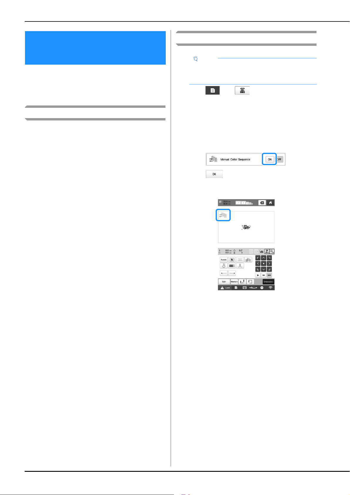
58
The thread colors assigned to each needle bar can be
manually specified/managed. In addition, the thread colors
can be assigned to needle bars automatically and more
efficiently than when the settings are normally specified.
Convenience of the manual color sequence
The manual color sequence is convenient when the machine
is being used under the following conditions.
■ When using embroidery data that has no
thread color information, such as with DST
files
The thread spools to be used can easily be selected for
data with no thread color information. (For details, refer to
“SPECIFICATIONS” on page 190.)
■ When the same combination of thread colors
is always used
If specific thread colors are assigned to certain needle
bars, the thread color settings can be changed with the
needle bar number assignments, even when the pattern is
changed. The operation is simplified if the same thread
colors are always used.
■ When continuously embroidering with the
same needle bar settings
If the settings are specified normally, the needle bar
settings are canceled when the embroidering settings
screen appears after embroidering stops. However, with
[Manual Color Sequence], the needle bar settings
continue to be applied unless the pattern is deleted or the
machine is turned off.
This is useful if the same pattern is to be embroidered
continuously multiple times.
Specifying the manual color sequence
a
Touch , then .
The general settings screen appears.
b
Locate [Manual Color Sequence].
c
Touch [ON], and then select the manual color
sequence.
• When the machine is purchased, [OFF] is selected.
d
Touch to return to the previous screen.
The icon for [Manual Color Sequence] appears in the
screen.
SELECTING/MANAGING THREAD
COLORS FOR EACH NEEDLE BAR
[Manual Color Sequence]
Note
• The [Manual Color Sequence] cannot be changed
while operations are being performed in the
embroidering screen.
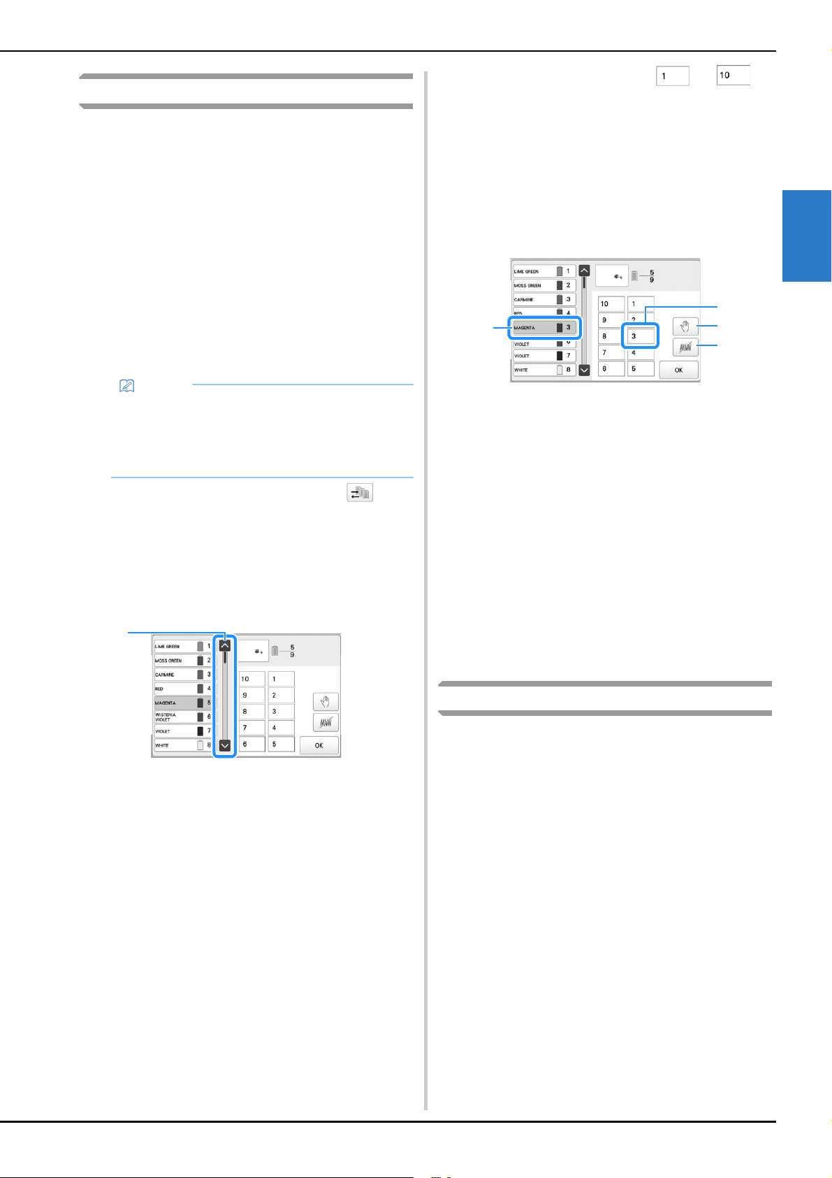
BASIC EMBROIDERY
59
2
Using the manual color sequence
■ Manually assign thread colors to all needle
bars
By specifying the thread colors used with this machine,
embroidery can continue more efficiently simply by
changing the needle bar assignments after a pattern is
selected. With the normal method of specifying settings,
only a maximum of 9 needle bars can be manually
assigned thread colors; however, with the manual color
sequence, all 10 needle bars can be assigned thread
colors.
(For details on specifying the settings, refer to page 121.)
■ Needle bar number settings
The needle bar used with each thread color can be
specified.
a
In the embroidering settings screen, touch .
A screen appears, allowing the needle bar numbers
to be selected.
b
From the thread color sequence display, select the
thread color whose needle bar is to be changed.
• If the desired thread color is not displayed, use the
scroll bar on the right side to display it.
1 Scroll bar
c
Touch a number button (between and ) to
select the number of the needle bar whose settings are
to be specified.
The needle bar number for the thread color selected
in step
b changes to the selected needle bar
number.
If the needle bar number was specified with reserved
needle bar settings, the color of the thread spool on
the left side changes to the specified thread color,
and the pattern in the pattern display area also
changes to the color of the specified needle bar.
1 Needle bar number specified with reserved needle bar
settings
2 Needle bar set to a different number (needle bar 5)
3 If a color is selected by touching this key, the machine
stops before embroidering the selected color.
4 If a color is selected by touching this key, the machine
does not embroider the selected color when
embroidering.
• 4 takes precedence if 3 and 4 are set at the same
time.
■ Initializing thread color settings
With the manual color sequence, the thread color
information on the machine can be initialized each time a
new pattern is selected, and then the needle bars can be
assigned. This allows the needle bar settings to be
specified without being affected by the thread color
information from the previous pattern.
Precautions on the manual color sequence
■ When embroidering a pattern containing 11 or
more colors
With the manual color sequence, the machine does not
monitor the timing for replacing thread spools. Since the
machine does not automatically stop and no message
indicating that the thread spool be changed appears, as
with the normal needle bar settings, follow the procedure
below to set the machine to stop with thread spools that
must be changed.
•Step
c of “Using the manual color sequence” on
page 59
• “Stopping the machine at the next color change” on
page 119
• “Specifying pause locations before embroidering” on
page 119
Memo
• Using the procedure described in “Reserved
needle bar and embroidery speed settings” on
page 121, the finished embroidery colors can be
checked in the screen if thread colors are assigned
to thread spools.
1
2
3
4
1
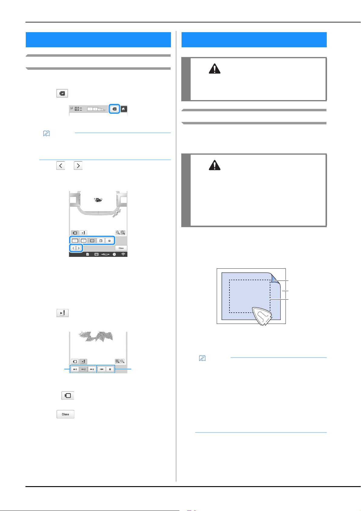
60
Checking a preview image
Display the preview image to check that the embroidery will
be performed as desired.
a
Touch .
The preview image is displayed.
b
Touch or to select the type of embroidery
frame holder, and then select the embroidery frame
you are going to use.
• After determining the type of embroidery frame
holder and size of embroidery frame that are best for
your embroidery, change the embroidery frame
holder and embroidery frame that are installed. The
machine will automatically detect the embroidery
frame holder and embroidery frame and change the
display.
c
Touch to check the embroidering order.
The stitch simulator screen appears.
1 Select the simulation speed.
2 Operation keys
• Touch to return to the embroidery frame
holder/embroidery frame selection screen.
d
Touch to return to the previous screen.
Attaching stabilizer (backing) to fabric
In order to prevent shrinkage of the stitching or misaligned
patterns, we recommend that stabilizer (backing) be used for
embroidering.
a
Using a steam iron, affix the iron-on stabilizer
(backing) to the back of the fabric.
• Use a piece of stabilizer which is larger than the
embroidery frame being used.
1 Adhesive side of iron-on stabilizer (backing)
2 Fabric (wrong side)
3 Size of the embroidery frame
PREVIEWING THE IMAGE
Memo
• A preview image in a landscape orientation cannot
be rotated to a portrait orientation, even if there is
space at the top and bottom.
1
2
PREPARING THE FABRIC
CAUTION
• Your machine can embroider fabric that is up
to 2 mm (5/64 inch) thick. If thicker fabric is
embroidered, the needle may bend or break.
CAUTION
• When embroidering on thin or stretch fabrics,
fabrics with a coarse weave or fabrics that
easily allow the stitching to shrink, be sure to
use stabilizer (backing) for embroidering. If
stabilizer (backing) is not used while
embroidering, the needle may bend or break
or the pattern may become misaligned.
Memo
• When embroidering light or open designs on thin
fabrics, such as organza or lawn, use a water-
soluble stabilizer (backing). Water-soluble
stabilizers dissolve when washed, allowing you to
create beautiful embroidery that is not stiff.
• When embroidering fabric that should not be
ironed or when embroidering an area that is difficult
to iron, hoop a layer of the stabilizer (backing)
under the fabric in the embroidery frame without
ironing it.
b
a
c
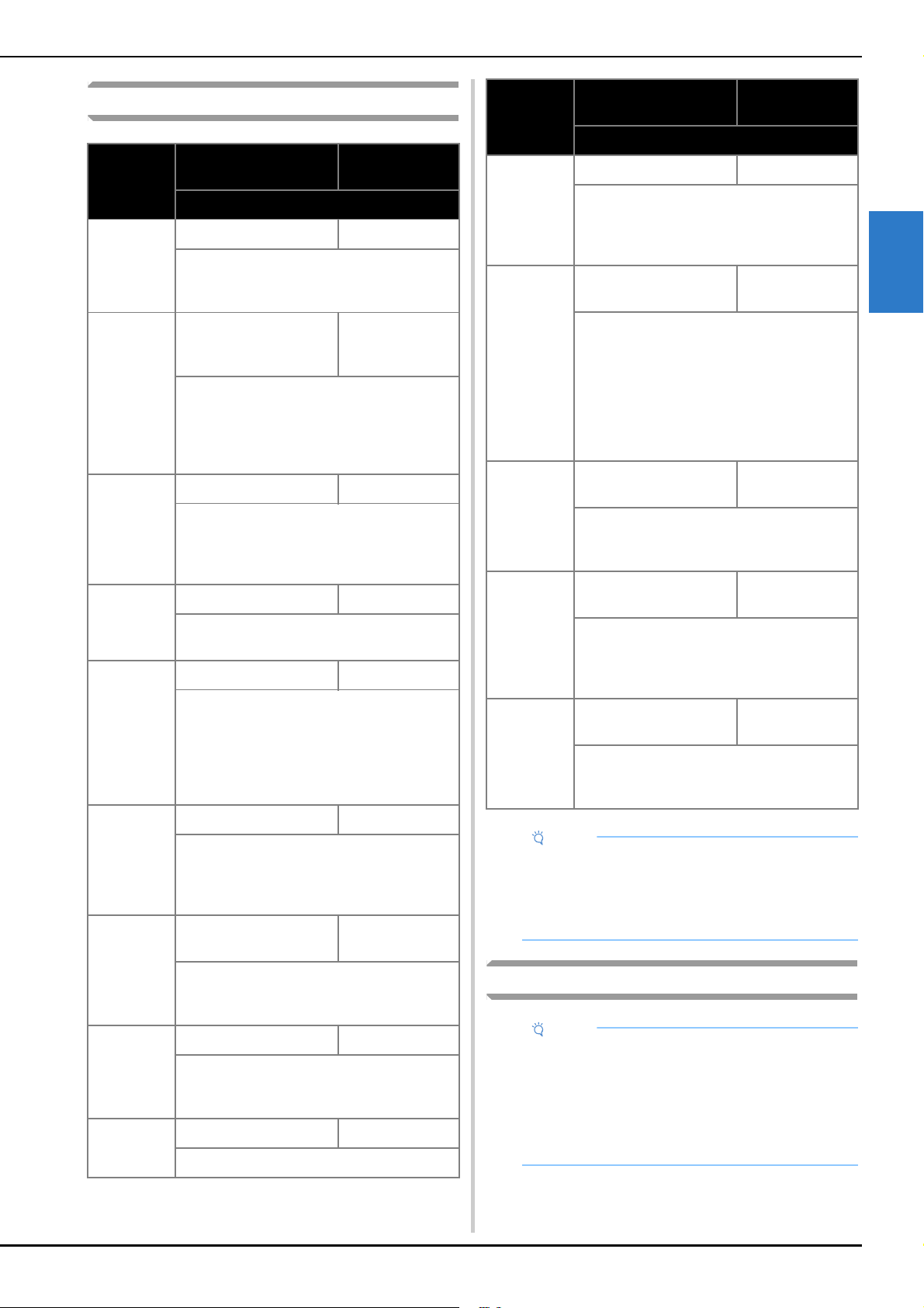
BASIC EMBROIDERY
61
2
Fabric/stabilizer compatibility chart
Hooping the fabric in the embroidery frame
Fabric/
Garment
No. of Backing Pieces
No. of Topping
Pieces
Comments
Terry cloth
1 tear-away 1 water-soluble
Increase density and/or satin stitch width.
Fine details and small lettering tend to get
caught in the terry loops.
Satin jacket
Heavy lining: None
Light or no lining: 1 tear-
away
None
If garment slips in frame, causing alignment
problems, wrap inner frame with masking
tape or fabric bias tape. This provides a rough
surface to grip garment and also helps
minimize frame burn.
Cotton
sheeting
1 tear-away None
High-density or highly detailed designs may
require more backing. If so, use two pieces of
lightweight backing instead of one piece of
heavy backing.
Denim
1 tear-away None
Reduce speed if needle begins to heat up and
the thread breaks.
Headwear
Optional Optional
Change needles more often than usual
because the buckram backing dulls needles
faster. A lightweight tear-away backing helps
reduce thread breaks and regulates thread
tension. Use a topping on corduroy or foam
cap fronts.
Dress shirt
(woven)
1 tear-away None
High-density or highly detailed designs may
require more backing. If so, use two pieces of
lightweight backing instead of one piece of
heavy backing.
Golf shirt
1 cut-away or iron-on
cut-away
Optional
Use topping for designs containing small
lettering or a lot of detail, and also for piqué
knits.
Canton
fleece
1 tear-away Optional
Use a topping if the garment has a textured
surface, such as a basketweave or
pronounced twill.
Canvas
1 tear-away None
Frame tightly.
Corduroy
1 tear-away 1 water-soluble
A higher stitch density or more under
stitches, as well as a topping, may be
necessary to prevent stitches from sinking
into the fabric.
Lingerie or
silk
1 or 2 lightweight tear-
away
Optional
Reduce embroidery speed. The thread
tension should be low. Use topping for
designs with high detail or small lettering. For
very fine fabrics, use a thinner thread. Avoid
extremely narrow satin stitching on letters or
details; instead increase satin stitch width or
use a bean stitch. Gently remove (don’t pull)
backing and topping from garment.
Sweater knit
1 cut-away or iron-on
cut-away
1 water-soluble
Use tightly woven organza or curtain fabric
in a matching color as a backing for bulky or
“holey” knits.
Sweatshirt
1 cut-away or adhesive
tear-away
Optional
Highly detailed designs may require two
layers of lightweight cut-away stabilizer. Use
a topping on extra-thick fabrics or with fine-
detail designs.
T-shirt
1 light-weight cut-away
or iron-on cut-away
Optional
Use a topping on designs with fine detail or
small lettering. Tensions should be light.
Avoid stitch-heavy designs.
Note
• Due to the wide variety of fabrics and stabilizers
available, the above information should be used as
guideline only. If unsure of a particular fabric/
stabilizer combination, please embroider test a
sample prior to the finished garment.
Note
• If the fabric is not taut, the pattern may be
misaligned or the fabric may pucker. Follow the
procedure described below to firmly smooth the
fabric in the embroidery frame so that the fabric is
not loose. In addition, be sure to work on a level
surface when putting the fabric in the embroidery
frame.
Fabric/
Garment
No. of Backing Pieces
No. of Topping
Pieces
Comments
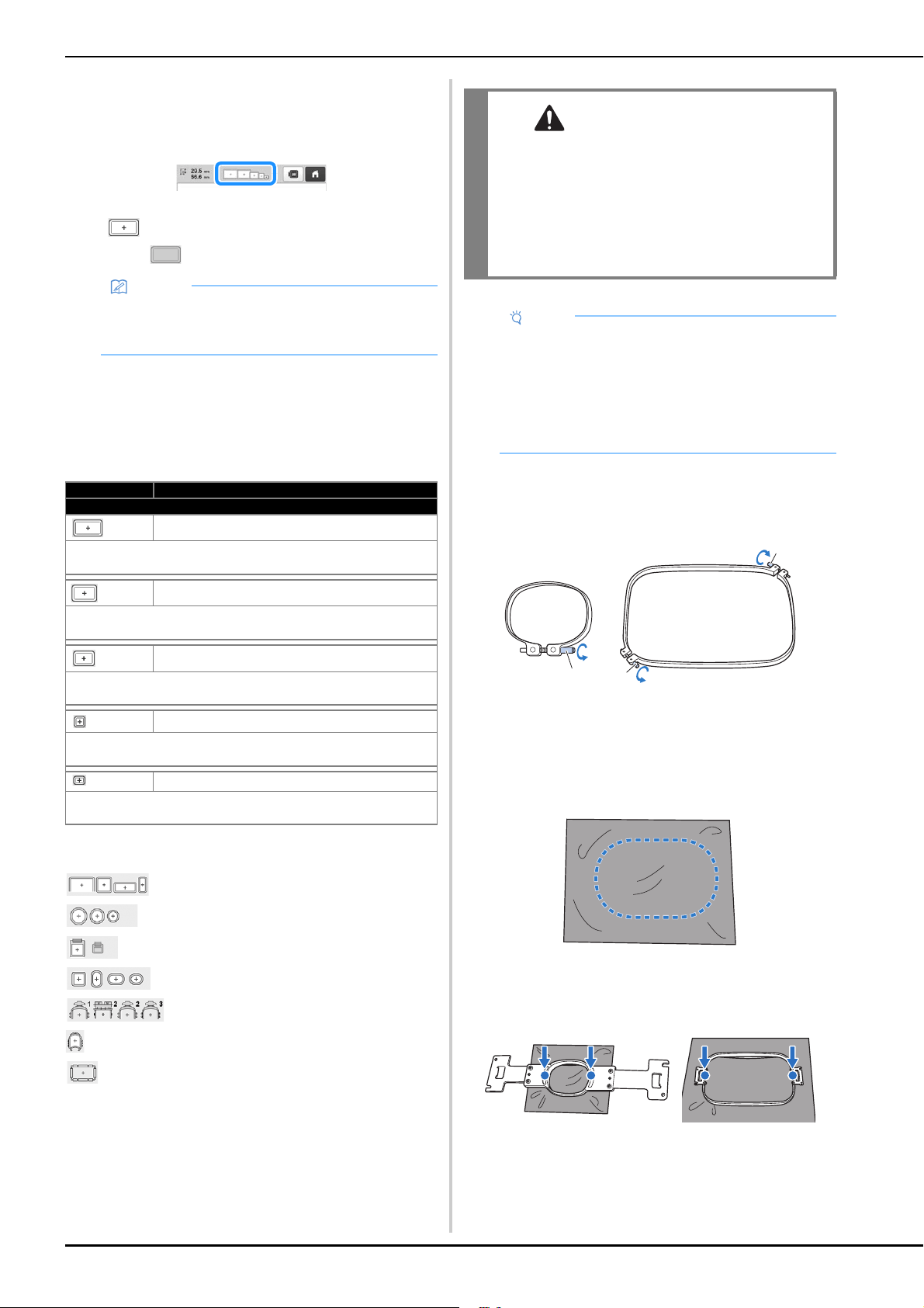
62
a
Select an embroidery frame.
From the sizes of embroidery frames indicated in the
screen, select the embroidery frame that you wish to
use.
Embroidery frames that can be used appear lighter
( ) embroidery frames that cannot be used appear
darker ( ).
■ Embroidery frame types
There are four sizes of embroidery frames included with
this machine, which are used with the included
embroidery frame holder A. For details on the uses for
each frame, refer to “Correctly using the embroidery
frames” on page 65.
If you use any of the optional embroidery frames, the
following icons appear in the screen.
: Embroidery frame holder B
: Embroidery frame holder C
: Embroidery frame holder D
: Embroidery frame holder E
: Cap frame
: Cylinder frame
: Magnetic sash frame
■ Hooping the fabric in the embroidery frame
a
Loosen the screw on the outer frame.
1 Small or medium embroidery frame
2 Extra-large, extra-large (optional) or large embroidery
frame
3 Screw
b
Place the stabilizer and fabric with right side up on top
of the outer frame.
• The outer frame does not have a front or back side.
Either side can be used as the front.
c
Press the inner frame into the outer frame.
• Be sure that there are no wrinkles in the fabric after it
is hooped in the embroidery frame.
Memo
• If the embroidery frame holder is not attached to
the machine, the embroidering area will not display
the correct frame size. (page 64)
Icon Name
Embroidery area
Extra-large embroidery frame
360 mm (W) × 200 mm (H)
(14 inches (W) × 7-7/8 inches (H))
Extra-large embroidery frame (optional)
300 mm (W) × 200 mm (H)
(11-3/4 inches (W) × 7-7/8 inches (H))
Large embroidery frame
180 mm (W) × 130 mm (H)
(7-1/8 inches (W) × 5-1/8 inches (H))
Medium embroidery frame
100 mm (W) × 100 mm (H)
(4 inches (W) × 4 inches (H))
Small embroidery frame
60 mm (W) × 40 mm (H)
(2-3/8 inches (W) × 1-1/2 inches (H))
CAUTION
• Use the four included frames or recommended
optional frames.
• If the size of the embroidery frame is wrong,
the embroidery frame may hit the presser foot
and damage the machine, or cause injury to
the user. (For details on embroidery frames,
refer to page 66.)
Note
• The embroidery frame indicators show all
embroidery frame sizes in which the embroidery
pattern can be embroidered. Be sure to use an
embroidery frame of the most suitable size. If the
embroidery frame that is too large is used, the
pattern may be misaligned or the fabric may
pucker. (page 65)
c c
c
a
b
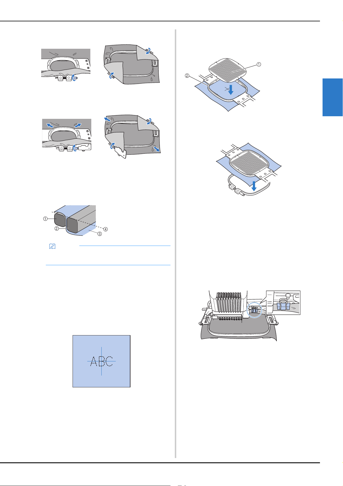
BASIC EMBROIDERY
63
2
d
Lightly tighten the screw.
e
Securely tighten the screw, and then check to make
sure that the fabric is taut.
• Use the 3 way screwdriver to tighten the screw
securely.
• After securing the fabric, lightly tapping it should
produce a drum-like sound.
• Firmly clamp together the inner and outer frames so
that their tops are even.
■ Using the embroidery sheet
In order to hoop the fabric so that the pattern will be
embroidered in the correct position, use the guidelines on
the embroidery sheet to accurately align the fabric in the
frame.
a
With a fabric marker, mark the area of the fabric you
want to embroider.
b
Place the embroidery sheet on the inner frame. Align
the guidelines on the embroidery sheet with the marks
that you drew on the fabric.
c
Gently stretch the fabric, so that there are no folds or
wrinkles.
d
Remove the embroidery sheet.
■ Embroidering large pieces of fabric or heavy
clothing
When embroidering large pieces of fabric or heavy pieces
of clothing, use a clothespin or binder clip to fasten the
excess fabric to the embroidery frame so that it does not
hang down from the frame. Embroidering with excess
fabric hanging down from the embroidery frame may
prevent the frame from moving properly and may result in
a misaligned pattern.
• Use a clothespin or binder clip to fasten the excess
fabric to the embroidery frame.
1 Outer frame
2 Inner frame
3 Right side of fabric
4 Top of inner and
outer frames are
even
Memo
• To correctly frame the fabric in the embroidery
frame, we recommend using a flat surface.
1 Guidelines
2 Inner frame
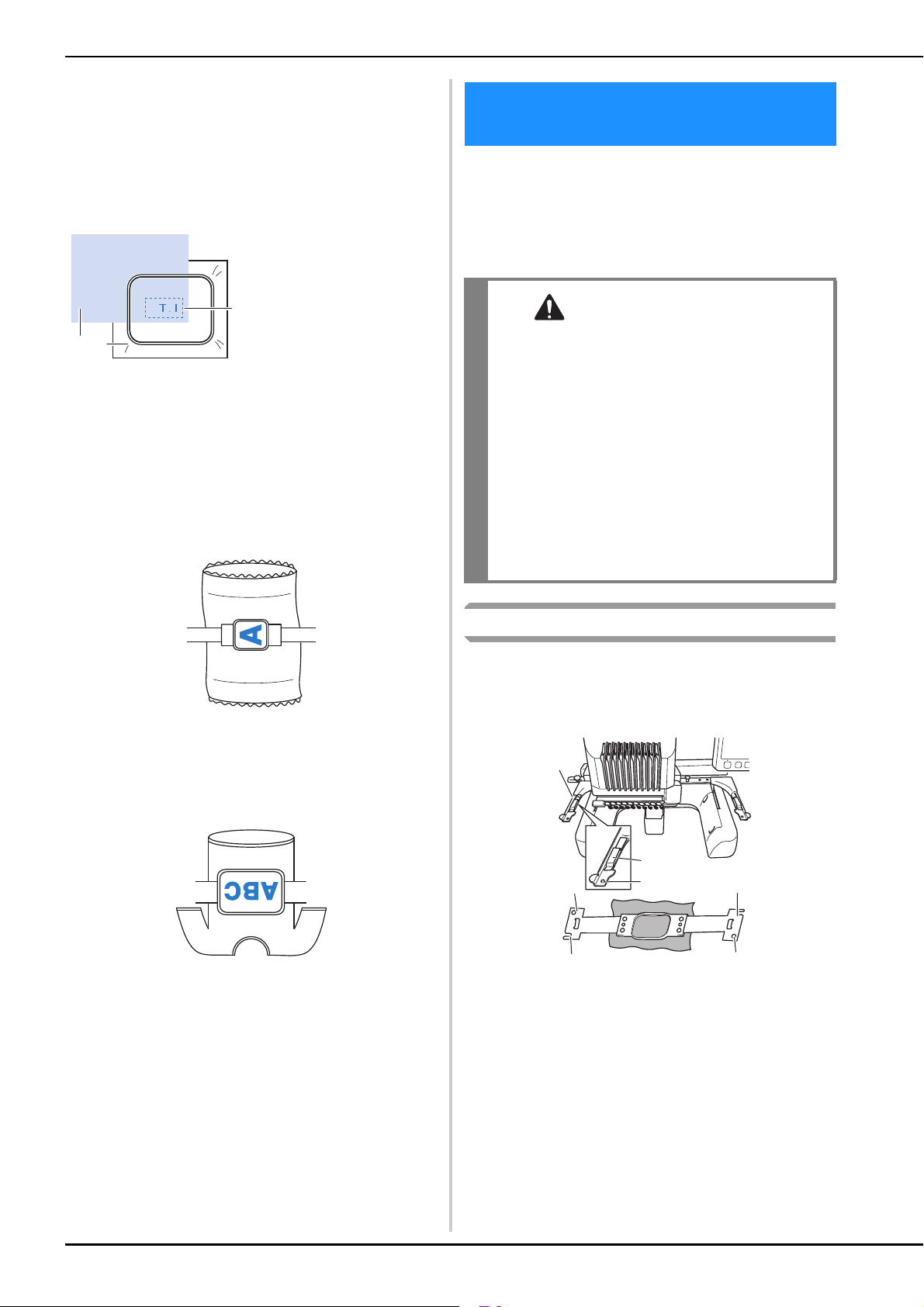
64
■ Embroidering small pieces of fabric
When embroidering small pieces of fabric that cannot be
hooped in an embroidery frame, use stabilizer material as
a base. After lightly ironing the fabric to the stabilizer
material, hoop it in the embroidery frame. If stabilizer
material cannot be ironed onto the fabric, attach it with a
basting stitch. After completing the embroidery, remove
the stabilizer material carefully.
■ Embroidering items, such as bags and tubular
items, that have limitations to being hooped in
the embroidery frame
Rotate the pattern before embroidery. For details on
rotating the pattern, refer to “Understanding the pattern
editing screen” on page 44.
Example: When embroidering a pillowcase
Rotate the pattern 90 degrees to the left before
embroidering.
Example: When embroidering a T-shirt
Rotate the pattern 180 degrees. Pass the machine bed
through from the waist of the T-shirt, not from the neck,
and attach the embroidery frame to the machine. This will
prevent the neck of the shirt from being stretched when
the embroidery frame is moving.
After hooping the fabric in the embroidery frame, attach
the frame to the machine. Embroidery frame holders A and
B are included accessories with this machine.
Install embroidery frame holder A when an included
embroidery frame is to be used. (For details on the
embroidery frame holders, refer to page 66.)
Attaching the embroidery frame
Adjust the width of the embroidery frame holder to the size of
the embroidery frame, and then attach the embroidery frame
to the machine. As an example, the procedure for attaching
the small embroidery frame is described below.
1 Left arm of embroidery frame holder
Move the arm of the embroidery frame holder to the left
or right to adjust it to the size of the embroidery frame.
2 Clip on embroidery frame holder
Insert the embroidery frame into the clips on the
embroidery frame holder.
3 Positioning pin
4 Holes
5 Positioning slots
1 Fabric
2 Stabilizer (backing)
3 Basting
a
c
b
ATTACHING THE EMBROIDERY
FRAME TO THE MACHINE
CAUTION
• If the embroidery frame is not correctly
attached it may hit the presser foot and
damage the machine, or cause injury to the
user.
• When attaching the embroidery frame, make
sure that the “Start/Stop” button is lit in red. If
the “Start/Stop” button is flashing in green,
the machine may start embroidering. If the
machine accidentally starts operating, injuries
may result.
• When attaching the embroidery frame, make
sure that the embroidery frame does not hit
any other part of the machine.
a
b
c
d
e
d
e
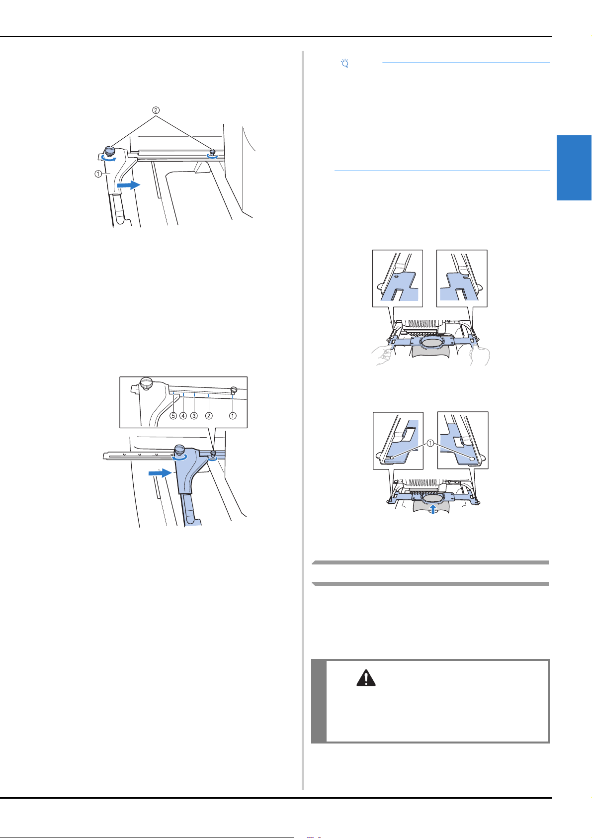
BASIC EMBROIDERY
65
2
a
Loosen the two left thumb screws on the embroidery
frame holder.
If the screw is too tight, please use the included 3 way
screwdriver.
1 Left arm
2 Thumb screws
The left arm of the embroidery frame holder can be
moved.
• Only loosen the thumb screws a maximum of 2 turns
counterclockwise. Do not remove the screw.
b
Move the left arm to align the screw on the right side
with the mark for the embroidery frame to be installed,
and then tighten the thumb screws.
For this example, align the small thumb screw with
mark 5.
1 Mark for extra-large embroidery frame
360 mm (W) × 200 mm (H)
(14 inches (W) × 7-7/8 inches (H))
2 Mark for extra-large embroidery frame
300 mm (W) × 200 mm (H)
(11-3/4 inches (W) × 7-7/8 inches (H)) (optional)
3 Mark for large embroidery frame
180 mm (W) × 130 mm (H)
(7-7/8 inches (W) × 5-1/8 inches (H))
4 Mark for medium embroidery frame
100 mm (W) × 100 mm (H)
(4 inches (W) × 4 inches (H))
5 Mark for small embroidery frame
60 mm (W) × 40 mm (H)
(2-3/8 inches (W) × 1-1/2 inches (H))
The embroidery frame holder is ready for the
embroidery frame to be attached.
c
Hold the embroidery frame level, and then
simultaneously align both the left and right mounts
with the embroidery frame holder clips.
• The inner frame should be on top.
d
Insert the embroidery frame until it snaps into place.
1 Make sure that the pins on the left and right arms of the
embroidery frame holder fit into the positioning slot and
hole on the embroidery frame.
Correctly using the embroidery frames
Various types of embroidery frames can be used with this
machine to suit your project.
In addition to the included embroidery frames, there are many
frames that can be used with this machine. (Refer to “Optional
accessories” on page 14.)
Note
• Please firmly tighten the two thumb screws with
included 3 way screwdriver. If the thumb screws
are not tightened, any of the following problems
may occur.
- The machine will detect the embroidery frame
size incorrectly.
- The starting position for the embroidery frame is
misaligned.
- The embroidery pattern is misaligned.
CAUTION
• Only use embroidery frames of the sizes
indicated in the screen, otherwise the
embroidery frame may hit the presser foot,
which may result in injuries.
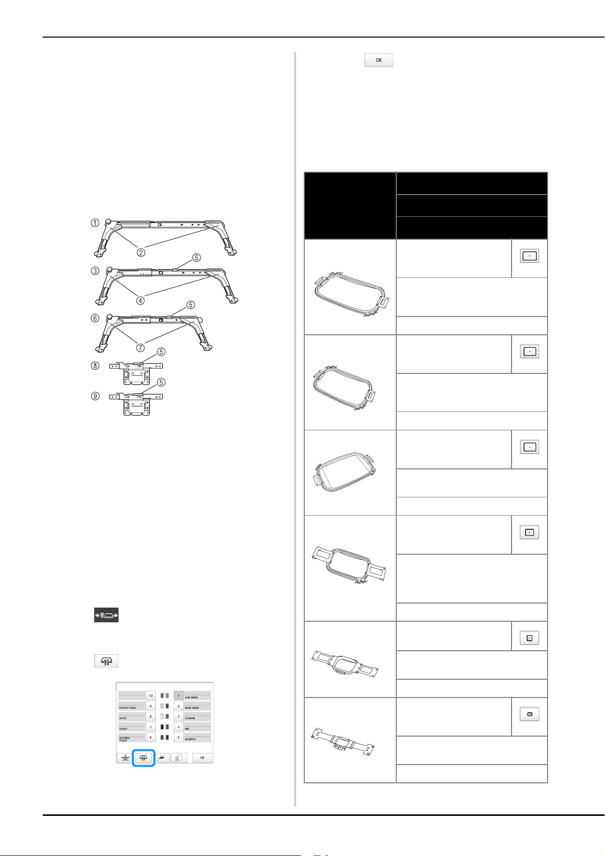
66
■ Embroidery frame holders
Two types of embroidery frame holders (embroidery frame
holder A and embroidery frame holder B) are included
with this machine.
Embroidery frame holder A is used with the four included
embroidery frames and the optional 300 mm (W) × 200
mm (H) (11-3/4 inches (W) × 7-7/8 inches (H)) hoop.
Embroidery frame holder B is used with the optional
embroidery frames. In addition, if you purchase optional
round frame set, clamp frame set or compact frame set,
specified frame holder C, D or E is included. For details on
which embroidery frame can be installed on each
embroidery frame holder, refer to “Types of embroidery
frames/frame holders and their applications” on page 66.
1 Embroidery frame holder A
2 White corner covers
3 Embroidery frame holder B
4 Light gray corner covers
5 Magnet
6 Embroidery frame holder C (optional)
7 Dark gray corner covers
8 Embroidery frame holder D (optional)
9 Embroidery frame holder E (optional)
■ When difficult to replace the embroidery
frame
Depending on the position of the needle bars, it may be
difficult to replace the embroidery frame. In that case,
follow the procedure described below to move the
embroidery frame.
a
Touch .
The needle bar move screen appears.
b
Touch .
The carriage automatically moves to a position
where the embroidery frame can easily be replaced.
• Touch to close the needle bar move screen
and to move the carriage to the previous position.
■ Types of embroidery frames/frame holders and
their applications
When the reference page is “*”, contact your authorized
Brother dealer.
Embroidery frames that use embroidery frame holder A
Embroidery frame
Embroidering area
Usage
Reference page
Extra-large embroidery
frame
360 mm (W) × 200 mm (H)
(14 inches (W) × 7-7/8 inches
(H))
Use when embroidering connecting
characters or patterns, combined
patterns or large patterns.
page 62
Extra-large embroidery
frame (optional)
300 mm (W) × 200 mm (H)
(11-3/4 inches (W) × 7-7/8
inches (H))
Use when embroidering connecting
characters or patterns, combined
patterns or large patterns.
page 62
Flat frame (optional) 300 mm (W) × 200 mm (H)
(11-3/4 inches (W) × 7-7/8
inches (H))
Use when embroidering jackets and
other thick garments.
*
Large embroidery
frame
180 mm (W) × 130 mm (H)
(7-1/8 inches (W) × 5-1/8
inches (H))
Use when embroidering patterns with a
size less than 180 mm (W) × 130 mm
(H) (7-1/8 inches (W) × 5-1/8 inches
(H)).
page 62
Medium embroidery
frame
100 mm (W) × 100 mm (H)
(4 inches (W) × 4 inches (H))
Use when embroidering standard-sized
patterns.
page 62
Small embroidery
frame
60 mm (W) × 40 mm (H)
(2-3/8 inches (W) × 1-1/2
inches (H))
Use when embroidering small-sized
patterns, such as name tags.
page 62
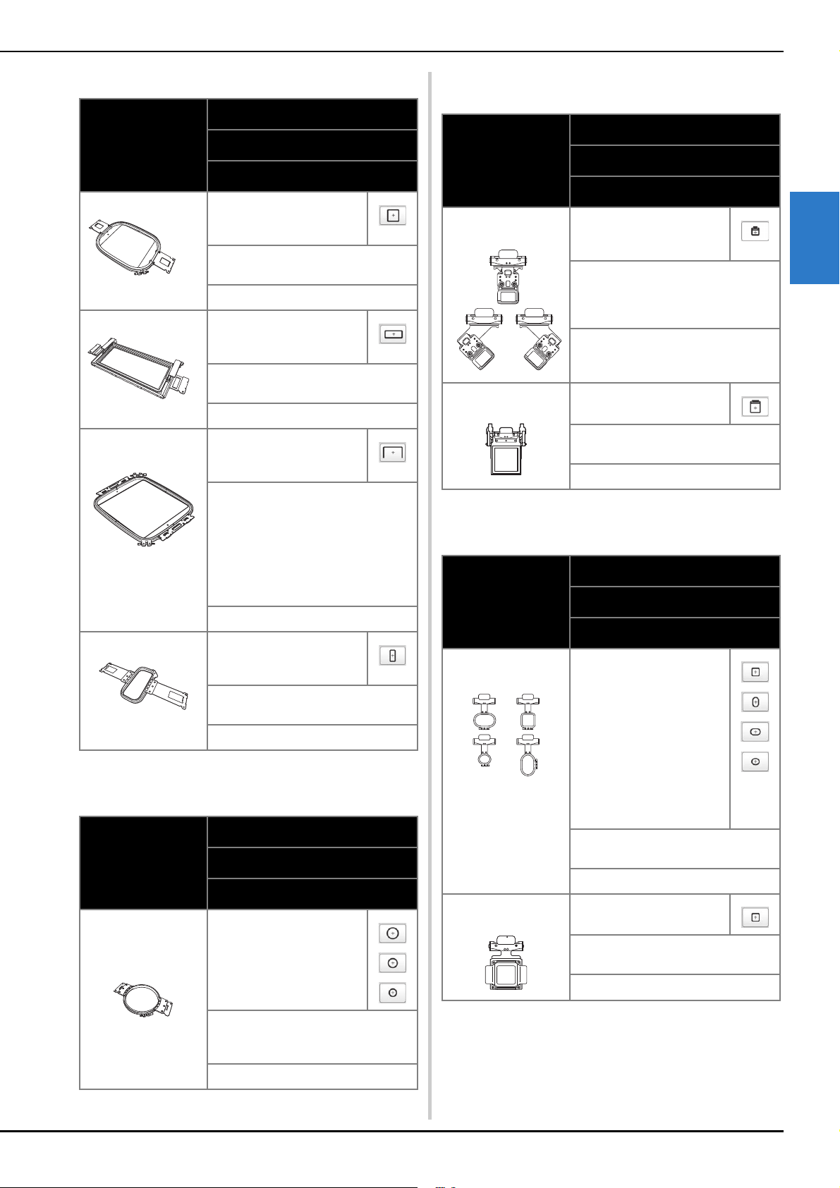
BASIC EMBROIDERY
67
2
Embroidery frames that use embroidery frame holder B
Embroidery frames that use embroidery frame holder C
(optional)
Embroidery frames that use embroidery frame holder D
(optional)
Embroidery frames that use embroidery frame holder E
(optional)
Embroidery frame
Embroidering area
Usage
Reference page
Quilt frame (optional) 200 mm (W) × 200 mm (H)
(7-7/8 inches (W) × 7-7/8
inches (H))
Use when embroidering pieces for
quilts.
*
Border frame (optional) 300 mm (W) × 100 mm (H)
(11-3/4 inches (W) × 7-7/8
inches (H))
Use when embroidering a long string of
characters or patterns.
*
Jumbo Frame
(optional)
360 mm (W) × 360 mm (H)
(14 inches (W) × 14 inches
(H))
Use when embroidering patterns that
have been split into two regions in
PE-DESIGN editing software and with a
size less than 200 mm (W) × 360 mm
(H) (7-7/8 inches (W) × 14 inches (H)) or
patterns with a maximum size of 350
mm (W) × 350 mm (H) (13-3/4 inches
(W) × 13-3/4 inches (H)).
page 140
Sleeve frame (optional) 70 mm (W) × 200 mm (H)
(2-3/4 inches (W) × 7-7/8
inches (H))
Use when embroidering long items
such as shirt sleeves.
*
Embroidery frame
Embroidering area
Usage
Reference page
Round frame (optional)
=diameter
100 mm (4 inches)
130 mm (5 inches)
160 mm (6 inches)
Use when adding a built-in embroidery
pattern to a sleeve. Select the frame
appropriate for the size of the pattern.
*
Embroidery frame
Embroidering area
Usage
Reference page
Clamp frame S
(optional)
45 mm (W) × 24 mm (H)
(1-3/4 inches (W) × 7/8
inches (H))
Use when embroidering specialty
shaped items that cannot be held in
normal frames, such as shoes and
gloves.
*
Clamp frame M
(optional)
100 mm (W) × 100 mm (H)
(4 inches (W) × 4 inches (H))
Use when embroidering specialty
shaped items, such as narrow bags.
*
Embroidery frame
Embroidering area
Usage
Reference page
Compact frame
(optional)
70: 70 mm (W) × 41 mm (H)
(2-3/4 inches (W) × 1-5/8
inches (H))
50: 50 mm (W) × 50 mm (H)
(2 inches (W) × 2 inches (H))
44: 44 mm (W) × 38 mm (H)
(1-3/4 inches (W) × 1-1/2
inches (H))
Vertical: 75 mm (W) × 33 mm
(H)
(2-15/16 inches (W) × 1-5/16
inches (H))
Use when embroidering logos or
patterns on small items.
*
Magnetic frame
(optional)
50 mm (W) × 50 mm (H)
(2 inches (W) × 2 inches (H))
Use to prevent the embroidery frame
from leaving traces in the fabric.
*
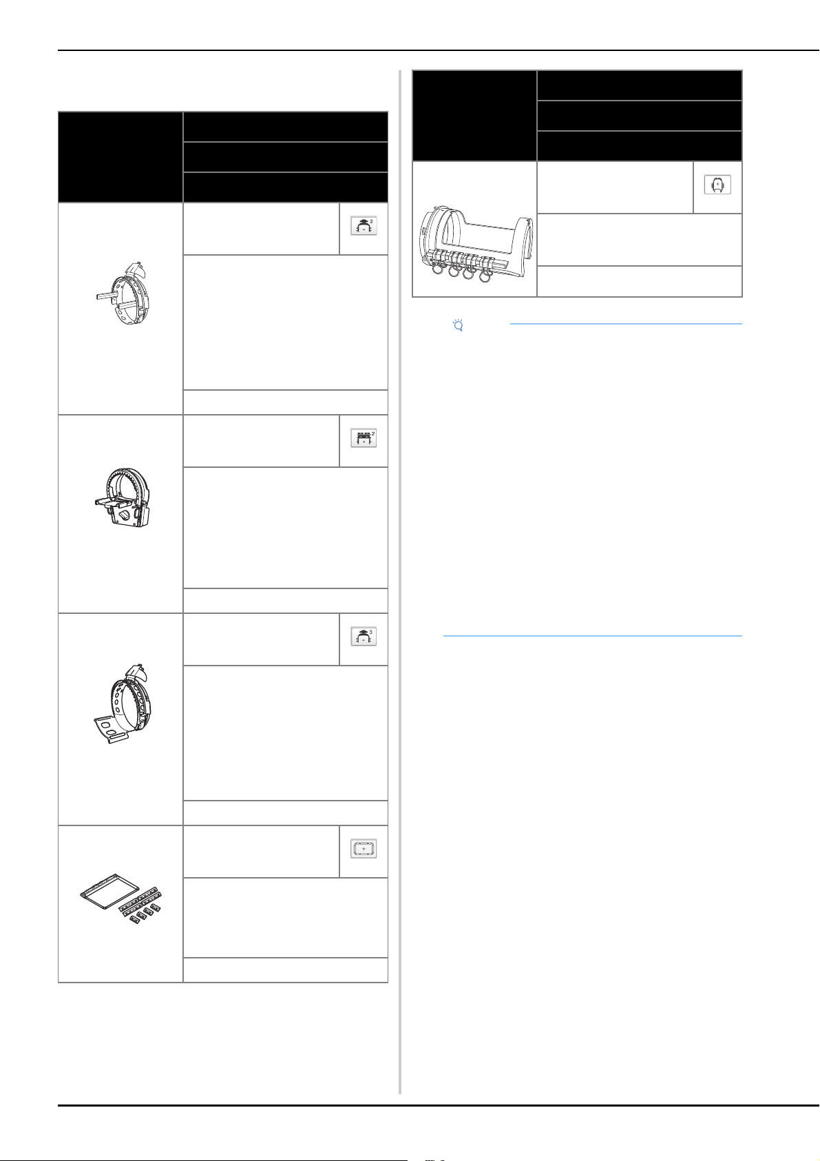
68
Embroidery frames that do not use embroidery frame
holders
Embroidery frame
Embroidering area
Usage
Reference page
Advanced cap frame 2
(optional)
130 mm (W) × 60 mm (H)
(5-1/8 inches (W) × 2-3/8
inches (H))
Use when embroidering caps. Baseball
(golf) caps, tulip hats and bucket hats
can be embroidered with these frames.
This frame cannot be used with hats
having a front area of 50 mm (2 inches)
or less, such as sun visors and
children’s hats. In addition, this frame
cannot be used with hats that have a
brim longer than 80 mm (3-1/8 inches).
*
Flat brim cap frame
(optional)
130 mm (W) × 60 mm (H)
(5-1/8 inches (W) × 2-3/8
inches (H))
Use when embroidering caps. In
addition to caps compatible with
advanced cap frame 2, this frame can
be used to embroider flat brim caps
and children’s caps. Compared with
advanced cap frame 2, this frame can
be used to embroider closer to the cap
brim.
*
Wide cap frame
(optional)
360 mm (W) × 60 mm (H)
(14 inches (W) × 2-3/8 inches
(H))
Use when embroidering caps. This
frame has larger embroidering area
than other cap frames. This frame
cannot be used with hats having a front
area of 50 mm (2 inches) or less, such
as sun visors and children’s hats. In
addition, this frame cannot be used
with hats that have a brim longer than
80 mm (3-1/8 inches).
*
Magnetic sash frame
(optional)
360 mm (W) × 200 mm (H)
(14 inches (W) × 7-7/8 inches
(H))
Use when embroidering connecting
characters or patterns, combined
patterns or large patterns. It is also
convenient to use when embroidering
quilt sash patterns.
*
Cylinder frame
(optional)
90 mm (W) × 80 mm (H)
(3-1/2 inches (W) × 3 inches
(H))
Use when embroidering tubular and
curved fabric, such as shirt sleeves and
turtlenecks.
*
Note
• The embroidery frame indicators show all
embroidery frame sizes in which the embroidery
pattern can be embroidered. Be sure to use an
embroidery frame of the most suitable size. If the
embroidery frame that is used is too large, the
pattern may be misaligned or the fabric may
pucker.
• All genuine embroidery frames that can be used
with PR series machines can be installed on this
machine.
• When embroidering with an optional embroidery
frame (jumbo frame, border frame, quilt frame, flat
frame or magnetic sash frame), the included wide
table must be installed onto the machine.
• Due to the weight of the embroidery frame and
fabric it is recommended that the included wide
table be used, to prevent the frame holder from
bending, which may result in the distortion of your
design or machine damage.
Embroidery frame
Embroidering area
Usage
Reference page
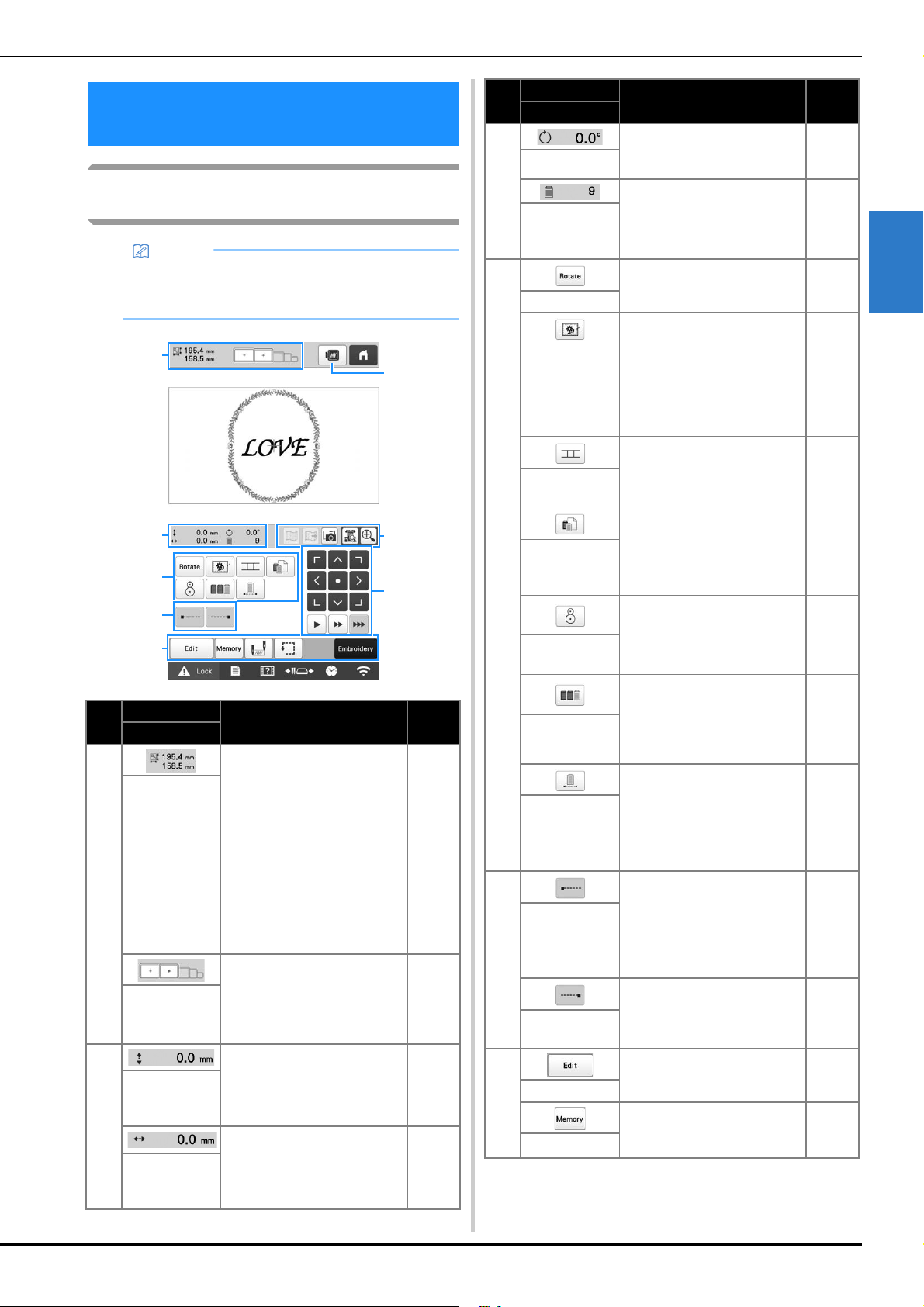
BASIC EMBROIDERY
69
2
Understanding the embroidering settings
screen
SPECIFYING EMBROIDERING
SETTING
Memo
• Keys available in this screen differ when you set
[Manual Color Sequence] to [ON] in settings
screen. (page 58, page 70)
No.
Display
Function Page
Key Name
1
Shows the size of the
embroidery pattern currently
displayed in the pattern
display area. The top value
shows the height and the
bottom value shows the
width. If the embroidery
pattern consists of multiple
patterns that have been
combined, the size of the
entire pattern, including all
patterns, is shown.
—
Pattern size
Shows the sizes of
embroidery frames that can
be used to embroider the
pattern currently displayed
in the pattern display area.
61
Embroidery
frame
indicators
2
Shows the vertical distance
that the pattern being
combined/edited is moved.
—
Distance from
center
(vertical)
Shows the horizontal
distance that the pattern
being combined/edited is
moved.
—
Distance from
center
(horizontal)
6
1
2
3
4
5
7
8
2
Shows the rotation angle that
the pattern being edited is
rotated.
—
Rotation angle
Shows the total number of
thread colors for the pattern
that is being edited.
—
Number of
thread colors
changes
3
Rotate the entire embroidery
pattern.
—
Rotate key
When stabilizer material is
not affixed to the fabric,
embroider basting stitches
along the outline of the
pattern to minimize
shrinkage of the stitching and
misaligned patterns.
99
Embroidery
basting key
Start pattern connecting
embroidering with the built-
in camera.
109
Pattern
connect key
Change the settings for
individual thread colors,
such as temporarily stopping
or skipping embroidering.
119
Individual
thread color
setting key
Align the embroidering
position using the built-in
camera.
78
Positioning
key
Specify that the
embroidering sequence for
multiple patterns that have
been combined be
rearranged by thread color.
71
Color sorting
key
Touch to embroider the
pattern in the same color,
regardless of specified color
changes. The entire thread
color sequence display will
appear in the same color.
120
Uninterrupted
embroidery
key/
Monochrome
4
Specify that automatic lock
stitch is embroidered at the
beginning of the pattern and
at the beginning of
embroidering after thread
trimming.
71
Lock stitching
(beginning)
key
Specify that automatic lock
stitch is embroidered when
the thread is trimmed.
71
Lock stitching
(end) key
5
Return to the pattern editing
screen.
—
Edit key
Save a pattern in the
machine’s memory, USB
media or a computer.
130
Memory key
No.
Display
Function Page
Key Name
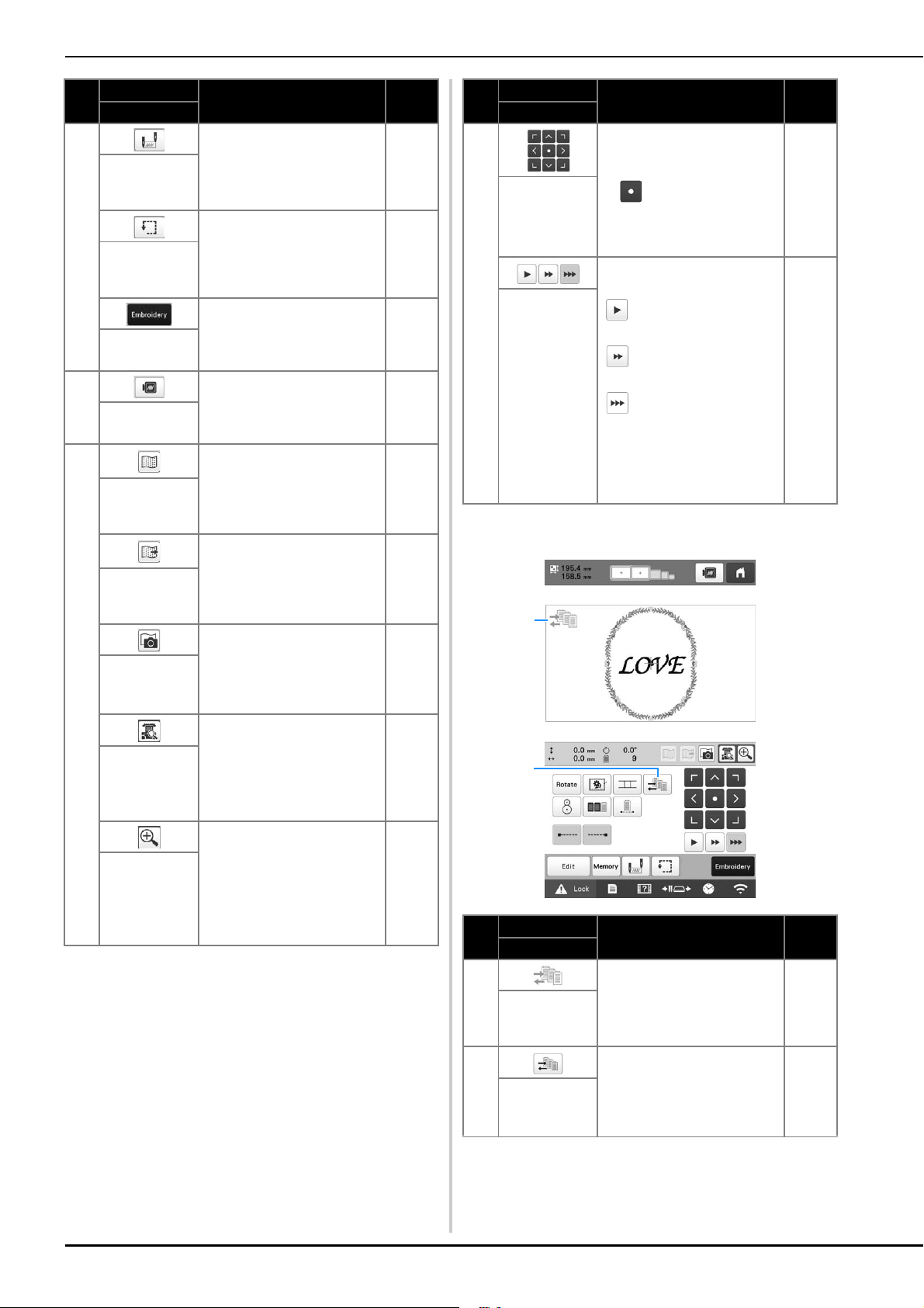
70
■ In the [Manual Color Sequence] mode
5
Specify the needle position
at the beginning of
embroidering and at the end.
126
Starting/
ending
position key
Move the embroidery frame
so that the embroidering
position can be checked.
79
Trial
embroidery
key
Finish all operations in the
embroidering settings screen
and continue to the
embroidering screen.
—
Embroidery
key
6
Display an image of the
pattern that is to be
embroidered so it can be
previewed.
60
Preview key
7
Display or hide the
background image scanned
in with the built-in camera.
73Background
image display
key
Save, onto USB media, the
background image scanned
in with the built-in camera.
73Save
background
image key
Scan (with the built-in
camera) fabric hooped in an
embroidery frame and
display it as a background
image for the pattern.
72
Fabric scan
key
View (on the LCD) the image
below the needle or display
an image of the edited
embroidery pattern at the
actual embroidering
position.
75,
79
Camera view
key
Display the image (after
touching the camera view
key) enlarged to double the
size.
This key is available even if
the camera view key was not
touched.
53
Camera zoom
key
No.
Display
Function Page
Key Name
8
Move the embroidering
position of the whole pattern
in the direction of the arrow.
(If is touched, the
embroidering position is
moved to the center of the
embroidering area.)
—
Positioning
keys
Select the speed to move the
frame.
: Touch to move the
frame by 0.1 mm (1/64 inch).
: Touch to move the
frame by 0.5 mm (1/32 inch).
: Keep touching to
move the frame at maximum
speed. When viewing the
camera image, the frame
moves by 2.0 mm (1/16
inch).
—
Frame
movement
speed keys
No.
Display
Function Page
Key Name
1
This icon appears when the
machine is in the [Manual
Color Sequence] mode.
58
Manual color
sequence
mode icon
2
Change the needle bar color
setting.
This key appears when you
set [Manual Color Sequence]
to [ON] in settings screen.
59
Manual color
sequence key
No.
Display
Function Page
Key Name
1
2
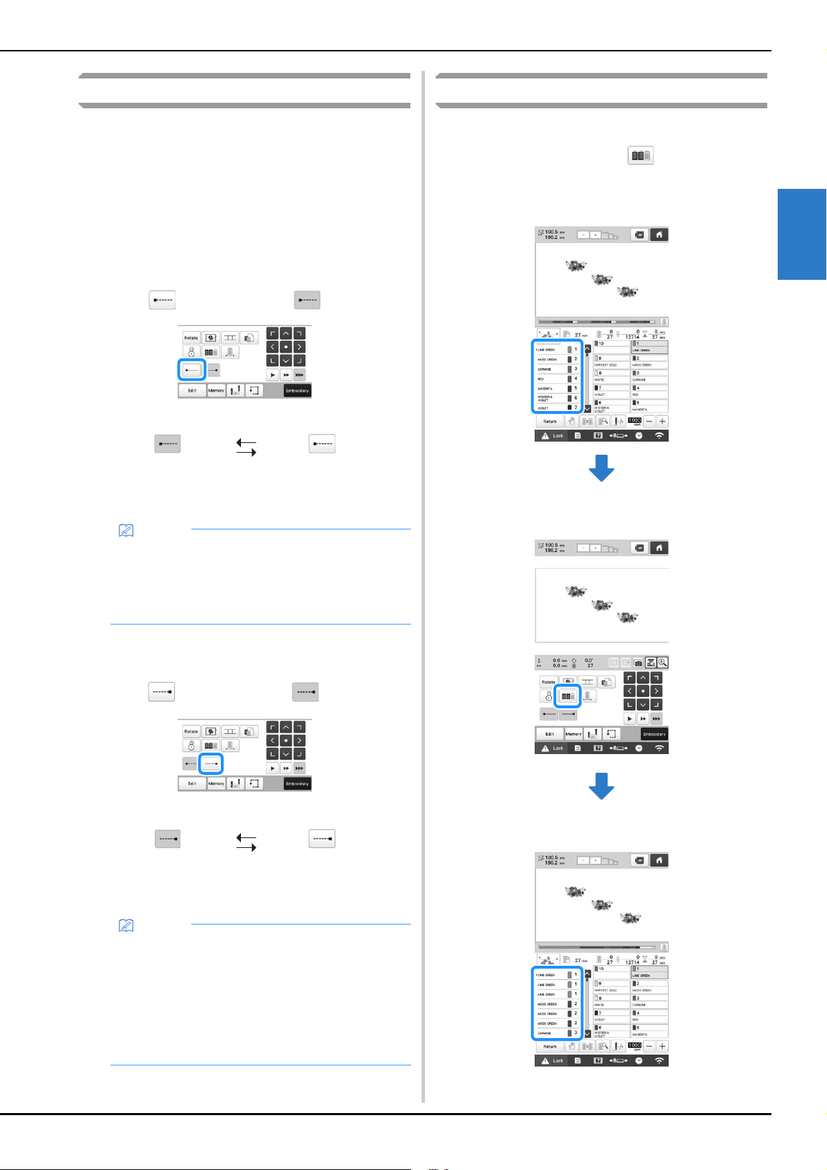
BASIC EMBROIDERY
71
2
Automatic lock stitch setting
When the machine is purchased, it is set to automatically
embroider lock stitches at the beginning of the pattern, before
embroidering after each thread color change, and before
trimming the thread.
■ To change the lock stitches being embroidered
at the beginning of the pattern, at the
beginning of embroidering each thread color
change and at the beginning of embroidering
after the thread trim.
a
Touch so that it changes to .
• Each touch of the key turns the setting either on or off.
■ To change the lock stitches being embroidered
before the thread is trimmed.
a
Touch so that it changes to .
• Each touch of the key turns the setting either on or off.
Thread color sorting
You can embroider while replacing the thread spool a
minimal number of times.
Before starting to embroider, touch in the embroidering
settings screen to rearrange the embroidering order and sort it
by thread colors.
Embroidery screen
Embroidering settings screen
Embroidery screen
Automatic lock
stitch setting turned
on
Automatic lock
stitch setting turned
off
Memo
• If the first stitch length is less than 0.8 mm (1/32
inch), the lock stitch won’t be inserted.
• If [Thread Trimming] is set [OFF] in the settings
screen, the lock stitch won’t be inserted.
(page 123)
Automatic lock
stitch setting turned
on
Automatic lock
stitch setting turned
off
Memo
• The automatic lock stitch setting stays the same
until the key is touched to turn it off. The setting
specified before the machine is turned off remains
selected the next time that the machine is turned
on.
• If [Thread Trimming] is set [OFF] in the settings
screen, the lock stitch won’t be inserted.
(page 123)
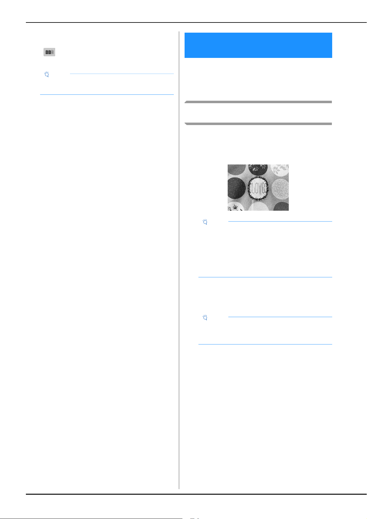
72
The embroidery color order is rearranged and sorted by thread
colors.
Touch to cancel the color sorting and embroider with
the embroidery color order.
The pattern is usually placed at the center of the
embroidery frame. If you want to change where in the
fabric the pattern will be embroidered, you can check the
position before starting embroidering.
Displaying the fabric while aligning the
embroidery position
The fabric hooped in the embroidery frame can be displayed
on the LCD so that the embroidery position can be aligned.
This feature can be used from the pattern editing screen and
embroidering settings screen.
a
Hoop the fabric in the embroidery frame, and then
attach the frame to the machine.
b
Select the pattern.
c
Specify the appropriate image settings in advance.
(page 73)
• Better scanning results can be achieved with the
appropriate settings.
Note
• This function does not work on overlapping
designs.
CHECKING THE EMBROIDERY
AREA
Note
• When installing the optional embroidery frame
holder D, embroidery holder E, Cap frame, or
Cylinder frame, the built-in camera cannot be used
to align the embroidering position.
• For details on using fabric thicker than 2 mm (5/64
inch), refer to “Positioning the pattern on thick
fabric” on page 74.
Note
• Make sure [Fabric Thickness Check] is set to [OFF]
when using light to medium weight fabrics.
(page 74)
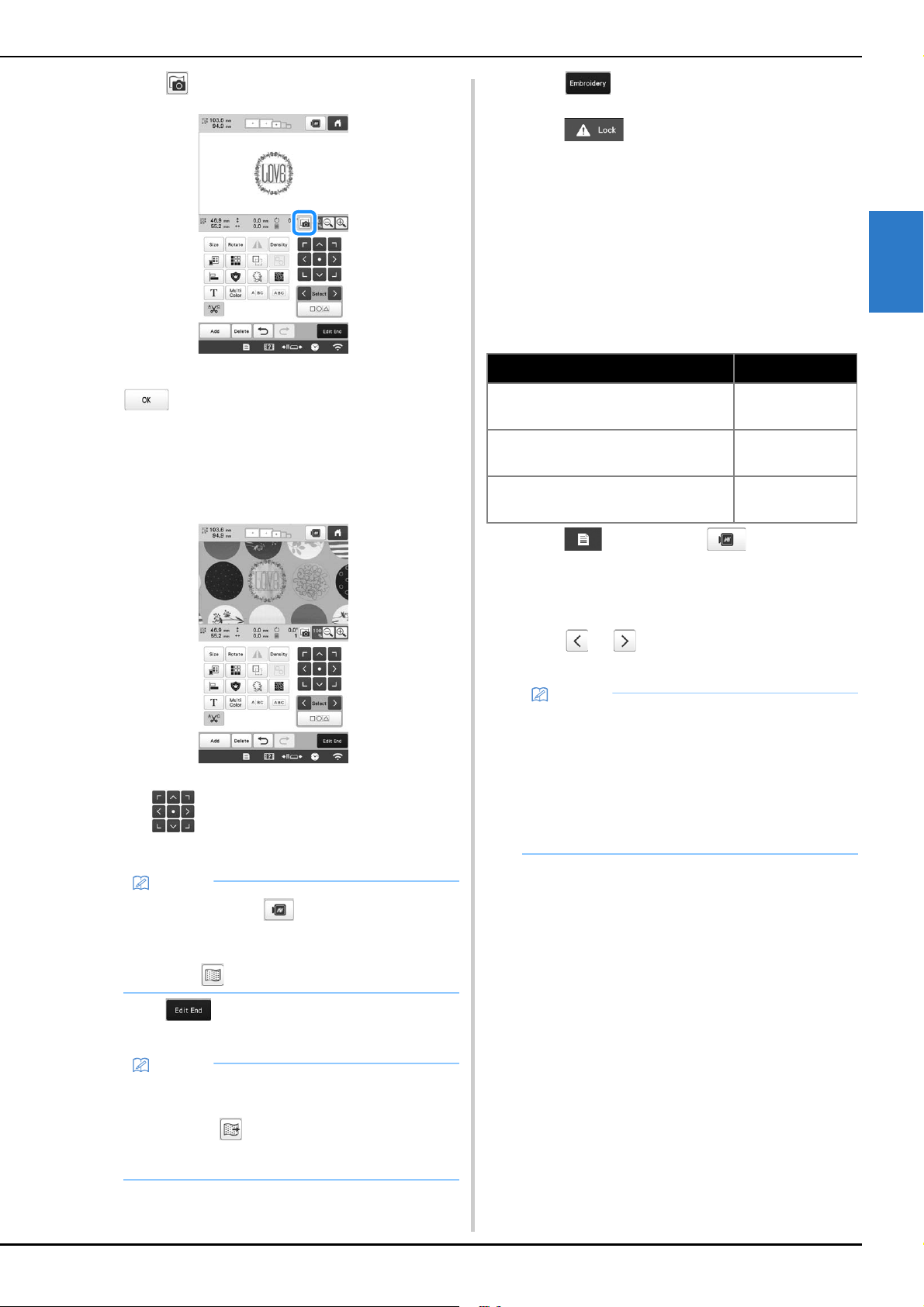
BASIC EMBROIDERY
73
2
d
Touch in the pattern editing screen.
e
When the message to start scanning appears, touch
.
The embroidery frame moves so the fabric can be
scanned.
f
When the fabric appears as a background for the
pattern, the pattern can be edited if it is necessary.
g
Use to align the pattern with the desired
embroidery position.
h
Touch to display the embroidering settings
screen.
i
Touch .
j
Touch , and then press the “Start/Stop”
button to start embroidering.
When embroidery is finished, the fabric displayed in
the background disappears.
■ Improving scanned images and camera images
The machine software adjusts images according to the
table installation setting.
The table installation setting must be selected before
scanning the fabric to display it as a background image for
a pattern or before using the built-in camera to display a
camera image of the fabric.
a
Touch , and then touch .
The embroidery settings screen appears.
b
Locate [Attached Table].
c
Touch or to select the table installation
setting.
Memo
• If necessary, touch to display a preview in
order to check the pattern position.
• The background can be displayed or hidden by
touching in the embroidering settings screen.
Memo
• The pattern can also be aligned from the
embroidering settings screen.
• By touching in the embroidery settings screen,
the background image can be saved to USB
media.
Table installation Setting
When no table is attached to the
machine
[No Table]
When the included wide table is
attached to the machine
[Wide Table]
When the optional tubular frame table
is attached to the machine
[Tubular Frame
Table]
Memo
• Better camera image and scanning results can be
achieved with the appropriate settings.
• When scanning in My Design Center with a
scanning frame, no setting needs to be selected for
[Attached Table].
• Be sure to install the wide table when using the
optional magnetic sash frame, border frame, quilt
frame, flat frame or jumbo frame.
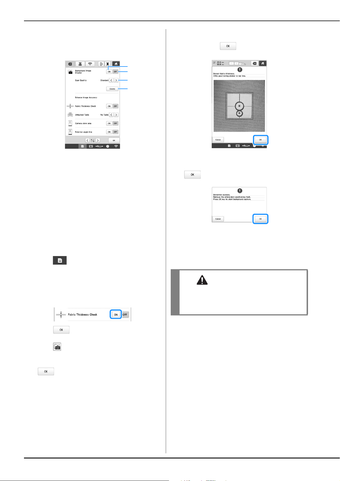
74
■ Displaying the fabric in the background
Whether or not the fabric is displayed in the background
can be specified. In addition, [Standard] or [Fine] can be
selected for the quality of the background image.
1 Set to [ON] to leave the fabric displayed in the
background.
2 When set to [OFF], the background will disappear.
3 Select the quality of the background image.
4 Remove the background image completely.
■ Positioning the pattern on thick fabric
When positioning the pattern on the fabric thicker than 2
mm (5/64 inch), the fabric may not be detected correctly.
In order for the fabric to be correctly detected, its
thickness must first be measured.
a
Hoop the fabric in the embroidery frame, and then
attach the frame to the machine.
b
Select the pattern.
c
Touch .
The embroidery settings screen appears.
d
Locate [Fabric Thickness Check] in the Settings pages.
e
Select [ON] to activate the setting.
f
Touch to return to the previous screen.
g
Touch .
h
When the message the machine moves appears, touch
.
i
Affix the embroidery positioning sticker to the fabric
within the area indicated by the red frame in the LCD,
and then touch .
j
When the following message appears, remove the
embroidery positioning sticker, and then touch
.
The embroidery positioning sticker affixed to the
fabric is detected, and then the embroidery frame
will be moved.
k
Continue with step f on page 73 to align the pattern
with the desired embroidery position.
1
2
3
4
CAUTION
• Use fabrics with a thickness of less than 2 mm
(approx. 5/64 inch). Using fabrics thicker than 2
mm (approx. 5/64 inch) may cause the needle to
break.
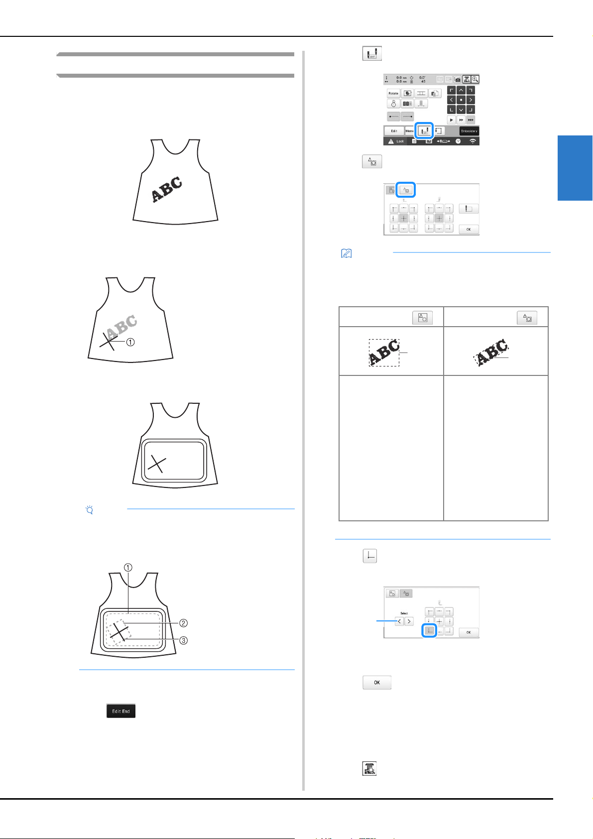
BASIC EMBROIDERY
75
2
Using the built-in camera
The camera built into this machine can be used to easily align
the embroidering position. This is useful for patterns which
need to be embroidered in particular position as shown
below.
a
Use a chalk pencil to mark the desired embroidering
position.
b
Hoop the fabric.
c
Select the pattern.
d
Touch to display the embroidering settings
screen.
e
Touch in the embroidering settings screen.
f
Select .
g
Touch to set the starting point to the left-lower of
the pattern.
1 If there are multiple patterns, select the pattern to be
used as the reference for the embroidering starting
position.
h
Touch .
i
Specify the appropriate image settings in advance.
(page 73)
• Better camera image results can be achieved with the
appropriate settings.
j
Touch .
1 Chalk pencil mark
Note
• When hooping the fabric in the embroidery frame,
make sure that the embroidery pattern will fit within
the embroidering area of the frame being used.
1 Embroidering area
2 Embroidery pattern
size
3 Chalk pencil mark
Memo
• The different methods of rotating a pattern and
aligning its position while checking the image
shown by the camera are described below.
1 Mask outline of pattern
When selecting When selecting
The mask is based on the
pattern after it has been
rotated. If there are
multiple patterns, the
mask is created around all
patterns.
Since the mask is based
on the pattern before it
has been rotated, this
method is useful when
embroidering in a
location where the
pattern cannot easily be
aligned. If there are
multiple patterns, a
pattern can be selected as
the reference for the
embroidering starting
position.
a
a
1
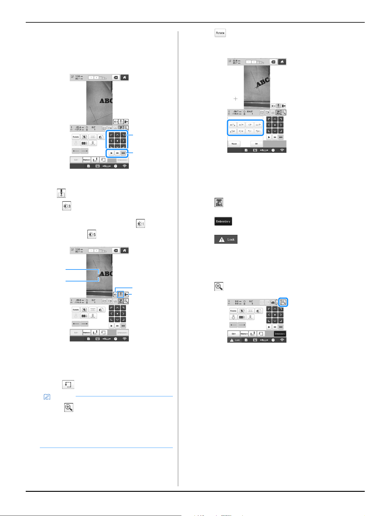
76
k
Touch the positioning keys to move the embroidery
frame until the chalk mark drawn on the fabric is
displayed in the camera view window.
Touch the frame movement speed keys to select the
speed to move the frame.
1 Positioning keys
2 Frame movement speed keys
l
Touch to display the needle drop point.
• Touch to change the brightness of the camera
image. The embroidering position can more easily be
checked by making the image darker ( ) on lighter
fabrics or lighter ( ) on darker fabrics.
1 Needle drop point
2 Chalk mark on the fabric
3 Each touch of this key changes the brightness of the
camera image.
4 Save the camera image on the external device.
• Touch to check the embroidering position.
m
Touch and adjust the orientation of the pattern
until the pattern is parallel with the chalk mark drawn
on the fabric.
• Touch the positioning keys to move the embroidery
frame until the pattern in the camera view window is
aligned with the chalk mark drawn on the fabric.
• If there are multiple patterns, all patterns are rotated,
not just the pattern used as the reference for the
embroidering starting position.
n
Touch to return to the previous screen.
o
Touch .
p
Touch , and then press the “Start/Stop”
button to start embroidering.
■ Enlarging the camera image
a
Touch .
Memo
• Touch to enlarge the camera view. By
enlarging the camera view, you can make a close
adjustment for the left-lower point of the pattern
moving the embroidery frame little by little. For
details, refer to “Enlarging the camera image” on
page 76.
1
2
1
3
4
2
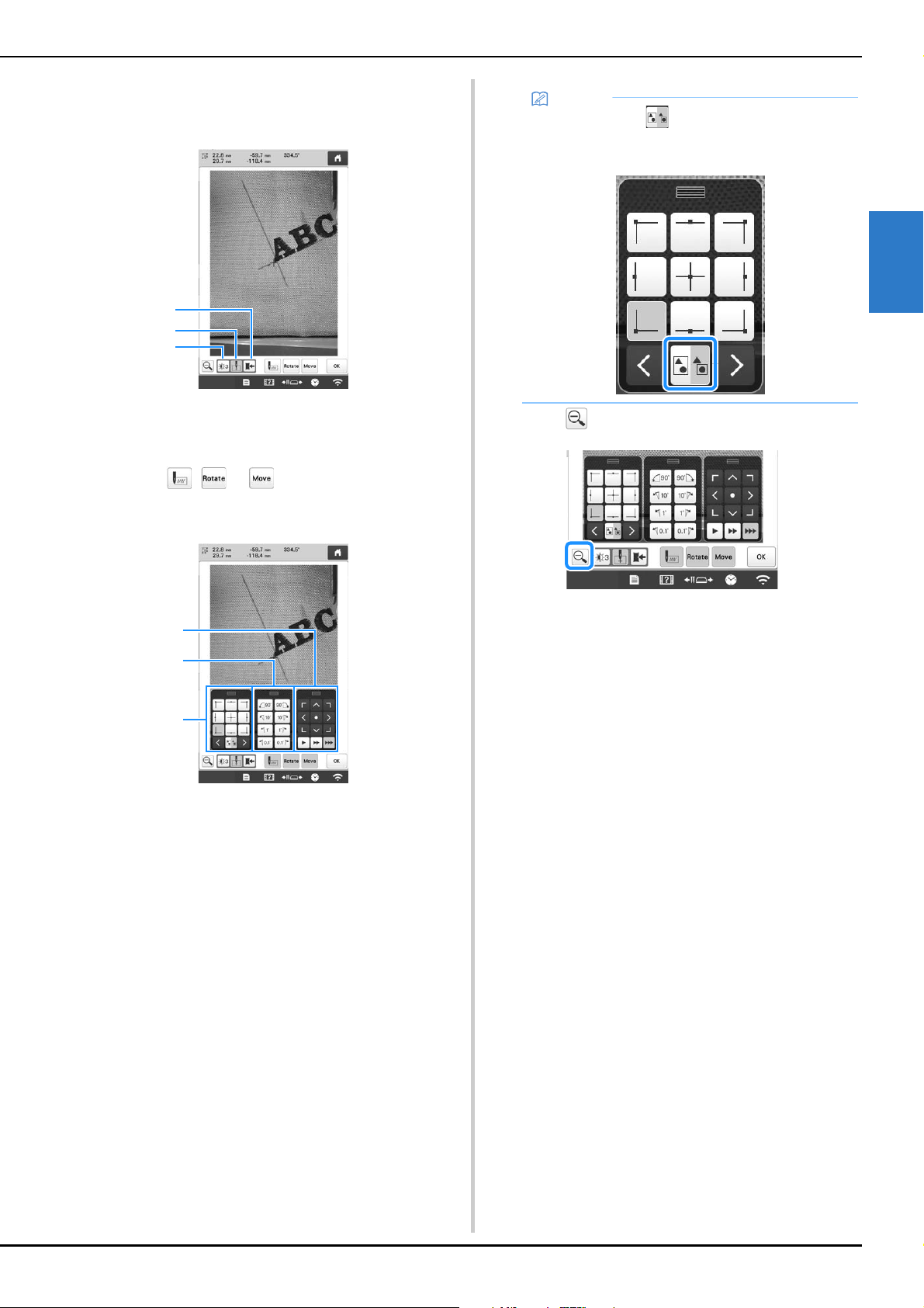
BASIC EMBROIDERY
77
2
b
The camera image is displayed enlarged.
• You can change the display settings that are specified
in the normal camera image display.
1 Save the camera image on the external device.
2 Specify the needle drop point mark on or off.
3 Each touch of this key changes the brightness of the
camera image.
c
Touch , or to display the keys for
specifying the starting position, rotating the pattern or
moving the embroidery frame.
1 Adjust the embroidering position by moving the
embroidery frame.
2 Rotate the pattern. If there are multiple patterns, all
patterns are rotated, not just the pattern used as the
reference for the embroidering starting position.
3 Specify the starting position of embroidering.
• While using these key panels in the enlarged camera
image, panels will be invisible to show the pattern
and the camera image clearly.
d
Touch to return to the normal camera image.
1
2
3
3
2
1
Memo
• When you touch , you can change the camera
mode. For details, refer to “Memo” in step
f of
“Using the built-in camera” on page 75.
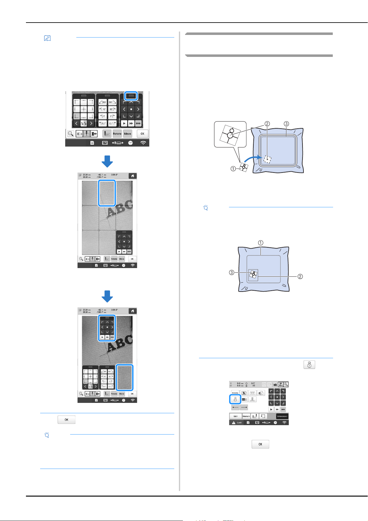
78
e
Touch to return to the previous screen.
Using the included embroidery positioning
sticker
Using the camera built into this machine and the included
embroidery positioning stickers, the embroidering position
can easily be aligned.
a
Affix an embroidery positioning sticker to the fabric at
the desired embroidering position. Align the center of
the large circle in the embroidery positioning sticker
with the center of the embroidery pattern.
1 Embroidery positioning sticker
2 Center of embroidery pattern
3 Embroidering area
b
In the embroidering settings screen, touch .
c
When the message to revert to original position and
angle appears, touch .
Memo
• The three key panels can be repositioned so that
the pattern can easily be viewed.
Touch the center of the top of a key panel to view
possible locations where the panel can be
repositioned. Touch the desired location to move
the selected key panel.
The possible locations for repositioning the panel
appear in gray.
The key panel moves to the selected location.
Note
• When using the camera to align the embroidering
position on thick fabric, use the thick fabric sensor
as described in “Positioning the pattern on thick
fabric” on page 74.
Note
• When hooping the fabric in the embroidery frame,
make sure that the embroidery pattern will fit within
the embroidering area of the frame being used.
1 Embroidering area
2 Embroidery pattern size
3 Embroidery positioning sticker
• Depending on the type of fabric to be used, it may
not be possible to easily remove the embroidery
positioning sticker. Before affixing the embroidery
positioning sticker, check how easily the sticker
can be removed by affixing it to a scrap of the
same type of fabric.
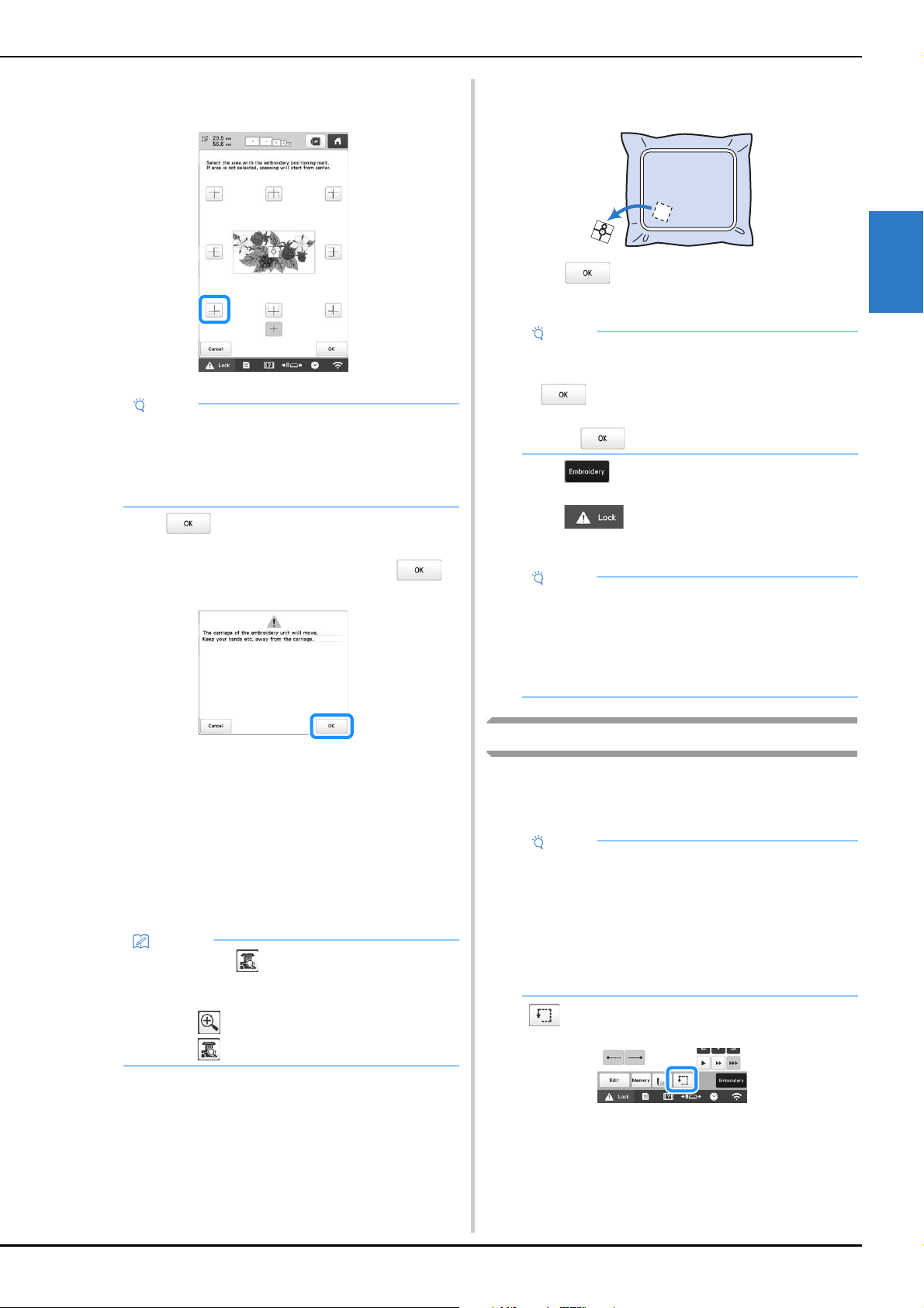
BASIC EMBROIDERY
79
2
d
From the reference points displayed on the screen,
select the point to be used for positioning the design.
e
Touch .
f
When the following message appears, touch .
The built-in camera automatically detects the
embroidery positioning sticker, and then the
embroidery frame is moved so that the reference
point is aligned with the center of the large circle in
the embroidery positioning sticker.
g
When the machine's built-in camera has finished
detecting the location of the embroidery positioning
sticker, the message stating to remove the embroidery
positioning sticker appears.
h
Remove the embroidery positioning sticker from the
fabric.
i
Touch .
j
Touch .
k
Touch , and then press the “Start/Stop”
button to start embroidering.
Checking the embroidery pattern
The carriage moves and shows the pattern position. Watch the
embroidery frame closely to make sure the pattern will be
embroidered in the right place.
Touch .
Note
• The built-in camera may not be able to detect the
embroidery positioning sticker if the four corners of
the sticker are not firmly affixed to the fabric. Use
tape to firmly affix the sticker to the fabric or try a
new sticker.
Memo
• You can touch to confirm the embroidery
position is correctly aligned before removing the
embroidery positioning sticker.
- Touch for the closer image.
- Touch again to return to the previous screen.
Note
• If the message that could not recognize the
embroidery positioning sticker appears, touch
, remove the embroidery positioning sticker,
and then affix it within the embroidering area. Then,
touch again.
Note
• After all of the included embroidery positioning
stickers have been used, new ones can be
purchased separately. When purchasing new ones,
check “Optional accessories” on page 14 for the
part code, and then contact your nearest
authorized Brother dealer.
Note
• If you are embroidering a large project such as a
jacket or curtains, your embroidering may be
interrupted by the presser feet not in use catching
on the fabric outside of the design area. Try to
stitch the design as close to the center of the
embroidery frame, using needle bars 3 through 7.
(For details on selecting the needle bar, refer to
page 57 or page 59.)
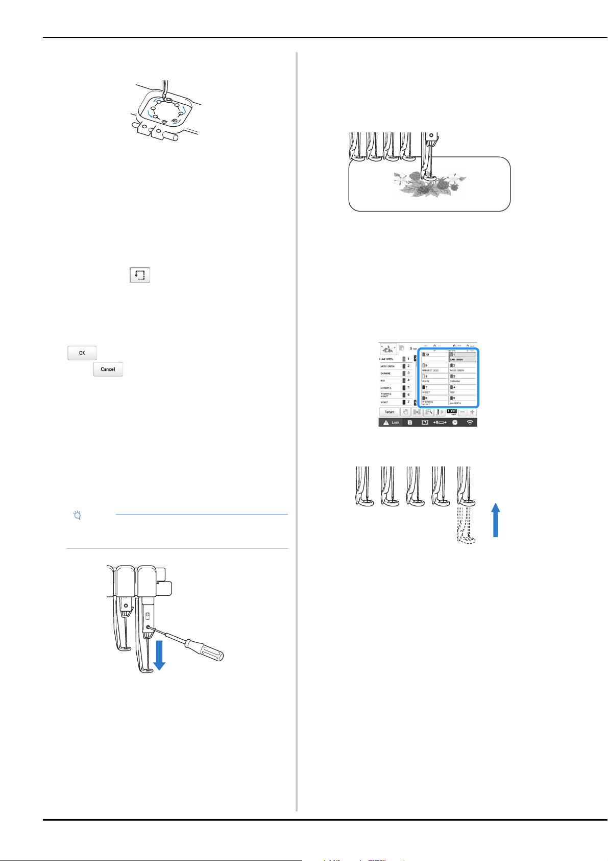
80
The presser foot is lowered and the embroidery frame
moves to show the embroidery area.
Carefully watch the movement of the embroidery frame
and check that the embroidery will stitch in the desired
location and that the embroidery frame does not hit the
presser foot.
■ Temporarily stopping to check the area
The embroidery frame can be temporarily stopped at a
desired position or the checking of the embroidering area
can be stopped.
a
When the embroidery frame moves to the desired
position, touch
again.
The embroidery frame stops moving, and the
message asking if you want to continue the trial
appears.
b
To continue moving the embroidery frame, touch
. To stop checking the embroidering area,
touch .
■ Finding the embroidering position
By locking the needle bar (securing the needle and presser
foot in the down position), the needle drop point can
easily be seen.
a
As shown in the illustration, insert the Allen
screwdriver into the hole in the needle clamp to slowly
lower the needle bar down till needle bar stops then
clicks into the lock position.
The needle and presser foot are locked in the down
position.
b
Touch the arrow keys in the embroidering settings
screen to move the embroidery frame so that the
needle drop point is at the center of the area where
you wish to embroider.
• With a USB mouse, your finger or the touch pen, drag
the pattern to move it.
• When specifying the starting of stitching, align the
needle drop point with the point specified as the
starting of stitching. (For details on specifying the
starting/ending of stitching, refer to page 126.)
■ Unlocking the needle bar
a
Display the embroidering screen, and then touch the
key for any needle bar other than the one that is
locked.
The needle bar is unlocked and will return to original
position.
Note
• Make sure that the needle is not lowered beyond
the positioning click into the fabric.
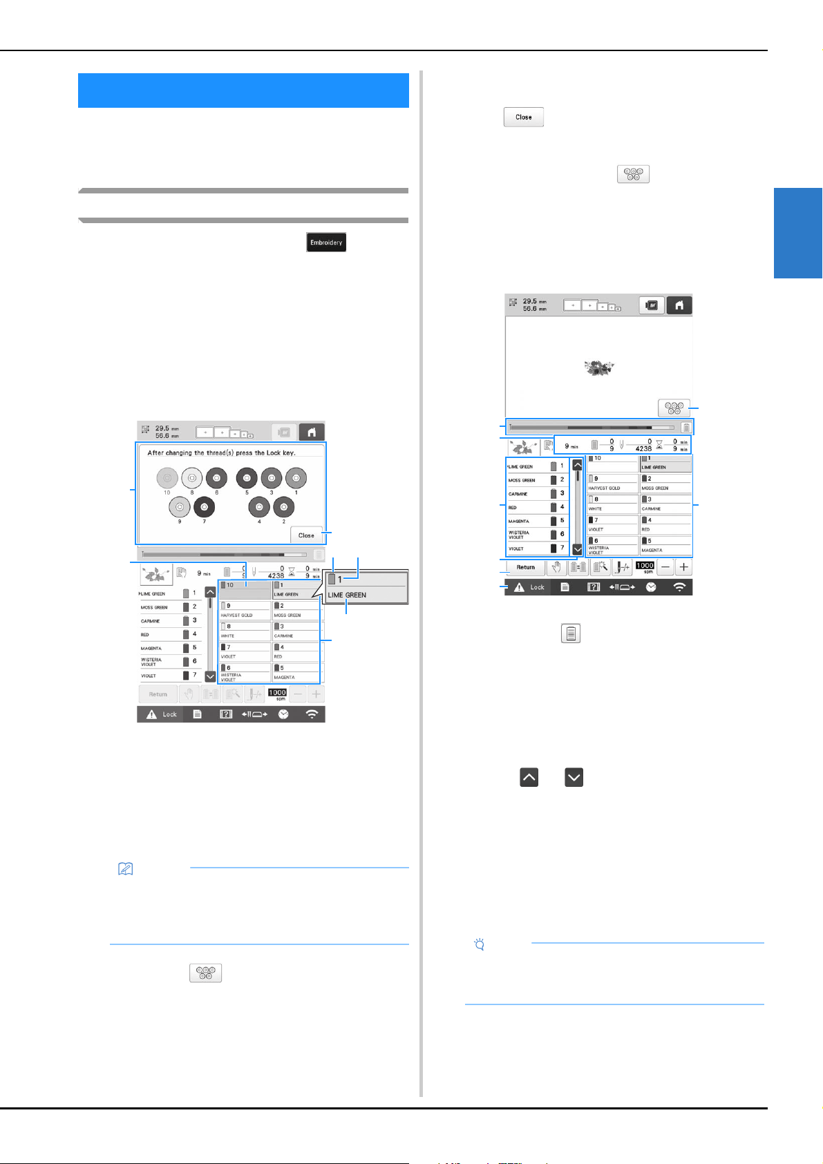
BASIC EMBROIDERY
81
2
Check the embroidering screen for information on which
needle bars should be threaded with specified thread
colors, and then thread the upper threads.
Checking the needle bars and thread colors
In the embroidering settings screen, touch to display
the embroidering screen. A screen indicating that the spools
need to be changed will appear if the thread colors from the
previous embroidery project will not be used. If you set
[Manual Color Sequence] to [ON] in the settings screen, the
message does not appear even if the thread spools need to be
changed. (Refer to “SELECTING/MANAGING THREAD
COLORS FOR EACH NEEDLE BAR [Manual Color
Sequence]” on page 58.)
Embroidering screen (For details on the screen, refer to
page 89.)
1 Thread information for the first to tenth needle bars
2 If no thread color name is displayed, that needle bar has
not been used.
If a thread color had been assigned to the needle bar on
a previously embroidered design, the needle bar will
show the previously assigned color.
3 Screen indicating that the spools be changed. (page 92)
This message appears when it is necessary for the
thread spools to be changed.
4 Minimize the screen indicating that the spools be
changed to .
5 Thread color
6 Needle bar number
7 Thread color name or number
If the thread color number [#123] is selected in the
settings screen, the thread brand will also be displayed.
(page 123)
Thread with the color name that appears below each needle
bar number is threaded on that needle bar.
a
Touch .
Current assigned colors are stored in the machine’s
memory, and the screen indicating that the spools be
changed is minimized to .
• In addition to checking the thread colors, information
such as the number of stitches and the embroidering
time can be checked and various embroidering
settings can be specified in the embroidering screen.
1 The embroidering progress is shown by the red mark in
the bar. Touch to display (in the indicator) only the
thread color being embroidered.
2 Shows the number of thread color changes, the number
of stitches, the embroidering time and the length of time
until the machine will stop.
3 Shows the thread colors, embroidering order and
number of the needle bar assigned to the thread colors.
A red triangle appears beside the thread color being
embroidered. In addition, the box changes to gray when
embroidering is finished.
4 Touch and to view the embroidering order and
needle bar number for thread colors that cannot be seen
in the screen.
5 Return to the embroidering settings screen.
6 When starting the machine or cutting the threads, touch
this button to unlock the machine, and then press the
“Start/Stop” button or thread trimming button.
7 Touch a key to move the selected needle bar to the
embroidering position. Use when threading the needle
with the automatic needle-threading mechanism.
8 Displays screen indicating that the spools be changed.
UPPER THREADING
Memo
• The thread spools for needle bars whose keys do
not appear in gray must be changed. When the
automatic needle-threading button is pressed, the
needle bar keys appear in gray.
2
1
4
3
56
7
Note
• Available keys are not the same if you set [Manual
Color Sequence] to [ON] in the settings screen.
(page 58)
1
2
5
3
7
4
6
8
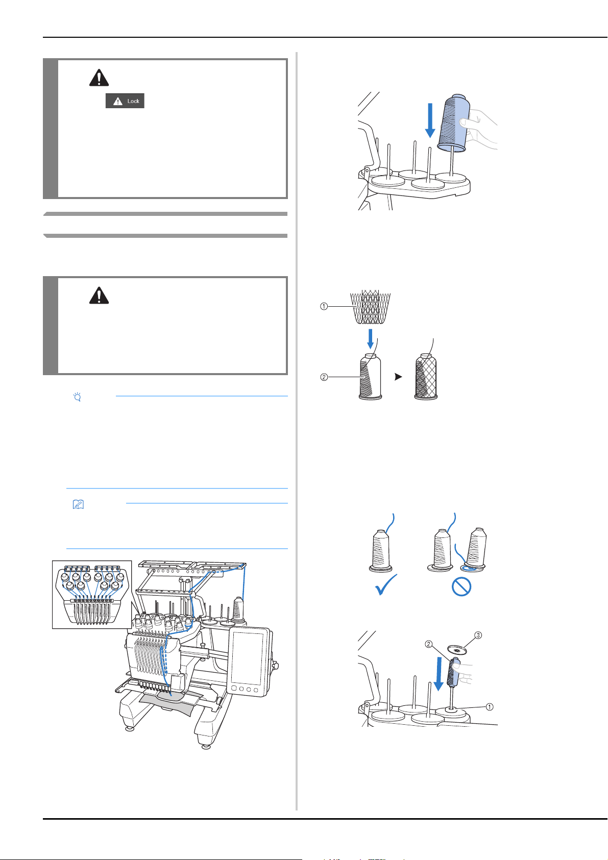
82
Upper threading
Use machine embroidery thread to thread the needle bars in
order, starting with needle bar 1.
a
On the spool pin, place a spool with the thread color
specified for the corresponding needle bar.
• When using metallic thread or any other strong
thread, place the included spool net over the spool.
If the spool net is too long, fold it once to match the
size of the spool before placing it over the spool.
It may be necessary to adjust thread tension when
using the spool net.
• Check that the spool stand has been completely
opened.
• When using small spools of thread, be sure to place
the included spool mat on the spool pin before
placing the spool on the pin.
• Place the thread in the center of the spool stand so
that the thread feeds off of the spool correctly and
does not get tangled around the spool pin directly
under the thread spool.
• Use spool cap on all spools of thread shorter than the
height of the spool pin.
1 Spool mat
2 Small spool
3 Spool cap
CAUTION
• When (unlock key) in the
embroidering screen is touched, the “Start/
Stop” button begins flashing in green and the
machine can start embroidering. If the upper
threading is being performed or the needle is
being threaded, be careful that the machine is
not accidentally started, otherwise injuries
may result.
CAUTION
• When threading the upper thread, carefully
follow the instructions. If the upper threading
is not performing correctly, the thread may
break or become tangled, causing the needle
to bend or break.
Note
• It is recommended that rayon or polyester machine
embroidery thread be used (120 den/2, 135 dtex/2,
40 weight (in Americas and Europe), #50 (in
Japan)).
• Certain types of thread may break or have
improper tension. In such a case, change the
thread.
Memo
• The path that the machine should be threaded is
indicated by a line on the machine. Be sure to
thread the machine as indicated.
1 Spool net
2 Thread
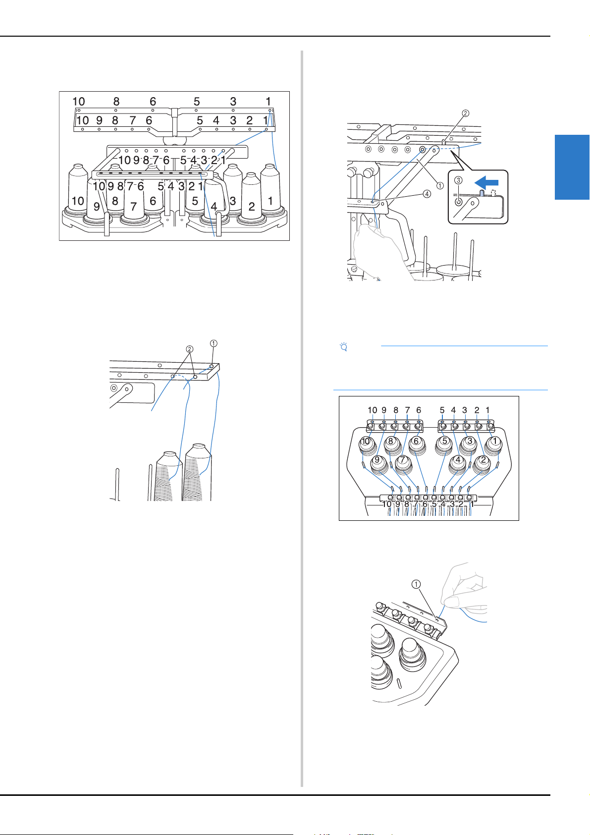
BASIC EMBROIDERY
83
2
The numbers indicate the thread path for each of the
numbered needle bars. Be very careful to correctly thread the
needle bars.
b
Pass the thread of a specified color through the holes
on the thread guide, making sure that you have the
thread color matched to the coordinating needle bar.
Pass the thread from spool pins 1, 3, 5, 6, 8 and 10
through the holes in both thread guides A and B.
Pass the thread from spool pins 2, 4, 7 and 9 through
the hole in thread guide B only.
1 Thread guide A (There are 6 holes in this thread guide)
2 Thread guide B (There are 10 holes in this thread guide)
c
Pass the thread through the hole (with the
corresponding needle bar number) in thread guide C,
then through the corresponding hole in thread guide D.
As an example, the threading for spool pin 1 is shown.
1 Thread guide C
2 Thread tension lever
3 Holes in thread guide C
4 Thread guide D
d
Pass the thread through the hole in the number 1 upper
thread guide and pull the thread toward you.
1 Hole in upper thread guide
Note
• Before threading, make sure to slide the thread
tension lever to the left so that the holes in thread
guide C are fully open.
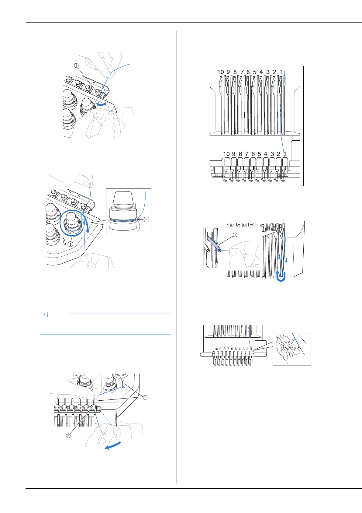
84
e
Hold the thread with both hands, and then pass it
under the guide plate from the right.
1 Upper thread guide plate
f
Wind the thread clockwise once around the number 1
thread tension disc.
1 Thread tension disc
2 Pass thread in a clockwise direction at this location on
the tension disks.
• Make sure that the thread is securely positioned in the
thread tension.
g
Lead the thread along the thread path and around the
correct thread guide pins as indicated on the machine,
then slip the thread under the number 1 middle thread
guide plate from the right.
1 Thread guide pin
2 Middle thread guide
• The path from the upper thread guide around the
thread tension disc and to the middle thread guide
(steps f through g) may differ depending on the
spool number. Passing the thread through the thread
guide pins is designed to prevent the thread from
becoming tangled. Be sure to follow the thread path
indicated on the machine.
h
Pass the thread along the number 1 slot to pass it
through the number 1 take-up lever hole from right to
left.
1 Thread take-up lever
i
Pass the thread down through the slot to the lower
thread guide, and then through the hole in the number
1 lower thread guide.
1 Hole in lower thread guide
Note
• All thread tension discs are threaded in clockwise
direction.
a
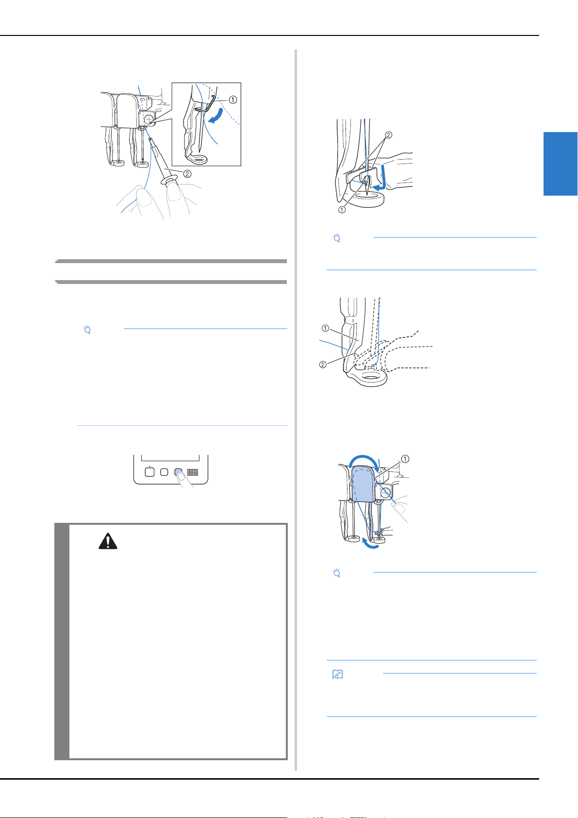
BASIC EMBROIDERY
85
2
j
Use the included threader to pass the thread into the
number 1 needle bar thread guide.
1 Needle bar thread guide
2 Threader
Threading the needle
Use the automatic needle-threading mechanism to thread the
needle.
a
Press the automatic needle-threading button.
The hook on the automatic needle-threading
mechanism passes through the eye of the needle.
b
Pull out about 150 mm (6 inches) of thread. Then, as
shown in the illustration, pass the thread under the
fork of the automatic needle-threading mechanism
from the right, and then catch the thread with the hook
that passes through the eye of the needle.
c
Pass the thread under the guide on the presser foot.
• Make sure that the thread securely passes through the
notch in the guide on the presser foot.
d
Securely pass the thread through the groove in the
thread cutter, and then lightly pull the thread to cut it.
Note
• The automatic needle-threading mechanism can
thread one needle at the embroidering position.
When this mechanism is used, be sure that the
needle bar that you want to thread is positioned at
the embroidering position, otherwise the automatic
needle-threading mechanism cannot be used at
the particular needle. If the needle bar is not at the
embroidering position, move it there. (page 86)
CAUTION
• If the needle is not fully inserted, the hook of
the automatic needle-threading mechanism
will not pass through the eye of the needle
during automatic needle threading, and the
hook may bend or the needle cannot be
threaded.
• If the hook of the automatic needle-threading
mechanism is bent or damaged, contact your
authorized Brother dealer.
• While the hook of the automatic needle-
threading mechanism is passed through the
eye of the needle, do not rotate the
handwheel. The automatic needle-threading
mechanism may be damaged. If you turn the
handwheel, the automatic needle-threading
mechanism will return to its initial position to
avoid damage.
1 Hook
2 Fork
Note
• When catching the thread with the hook, be careful
that the thread does not become loose.
1 Guide on presser
foot
2 Notch in guide on
presser foot
1 Groove in thread
cutter
Note
• If the thread is not correctly passed through the
groove in the thread cutter, the message [Wiper
error] appears and the needle cannot be threaded.
Be sure to securely pass the thread through the
groove.
• If enough thread is not pulled out, the thread
cannot be pulled through the thread cutter.
Memo
• The Wiper is the mechanism for pulling the thread
to back when the needle threader is used and
when the thread is trimmed during embroidery.
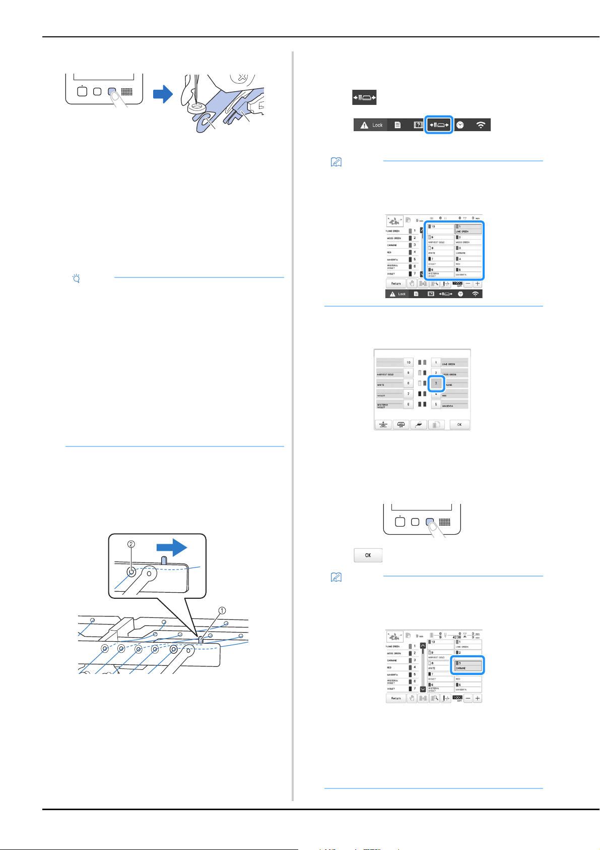
86
e
Press the automatic needle-threading button.
1 Automatic needle-threading mechanism
2 Wiper
• The threader moves back away from the needle. The
thread is pulled through the needle eye.
• The wiper comes out and catches the thread between
the needle and the threader.
• The threader goes back to the original home position.
This completes the upper threading for needle bar 1.
Thread the remaining needle bars in the same way.
f
When all upper threading is complete, be sure to slide
the thread tension lever for thread guide C to the right,
closing the holes in the thread guide.
• Embroidering with the holes in thread guide C fully
open may cause the thread to become tangled or
break.
1 Thread tension lever
2 Holes in thread guide C
■ Moving and threading a selected needle bar
You can move and thread a selected needle bar to the
embroidering position at any time.
a
Touch .
The needle bar move screen appears.
b
Touch the key for the needle bar that you wish to move
or thread.
The selected needle bar moves to the position of
embroidery.
c
Press the automatic needle-threading button while the
needle bar move screen appears.
d
Touch to return to the previous screen.
Note
• If the needle bar to be threaded is not moved to the
embroidering position, the needle cannot be
threaded with the automatic needle-threading
mechanism.
For the remaining needle bars, perform the
following operation to move the needle bar to the
embroidering position before trying to thread the
needle.
• If the thread is not taut, it may come out of the
thread tension disc. After upper threading is
finished, check again to make sure that the thread
is correctly passed into the thread tension disc.
(step
f on page 84)
a
b
Memo
• In the embroidering screen, touching the number of
the needle bar to be threaded will move the needle
bar to the embroidering position.
Memo
• In the embroidering screen, a blue frame appears
around the thread information box of the selected
needle bar.
• When changing one of the upper thread colors, it is
easy to re-thread by cutting the thread currently
being used between the spool and the thread guide
above the spool. Place the new spool on the spool
pin and tie the end of the new thread to the end of
the previous thread. Then pull the thread through to
the needle (page 92).
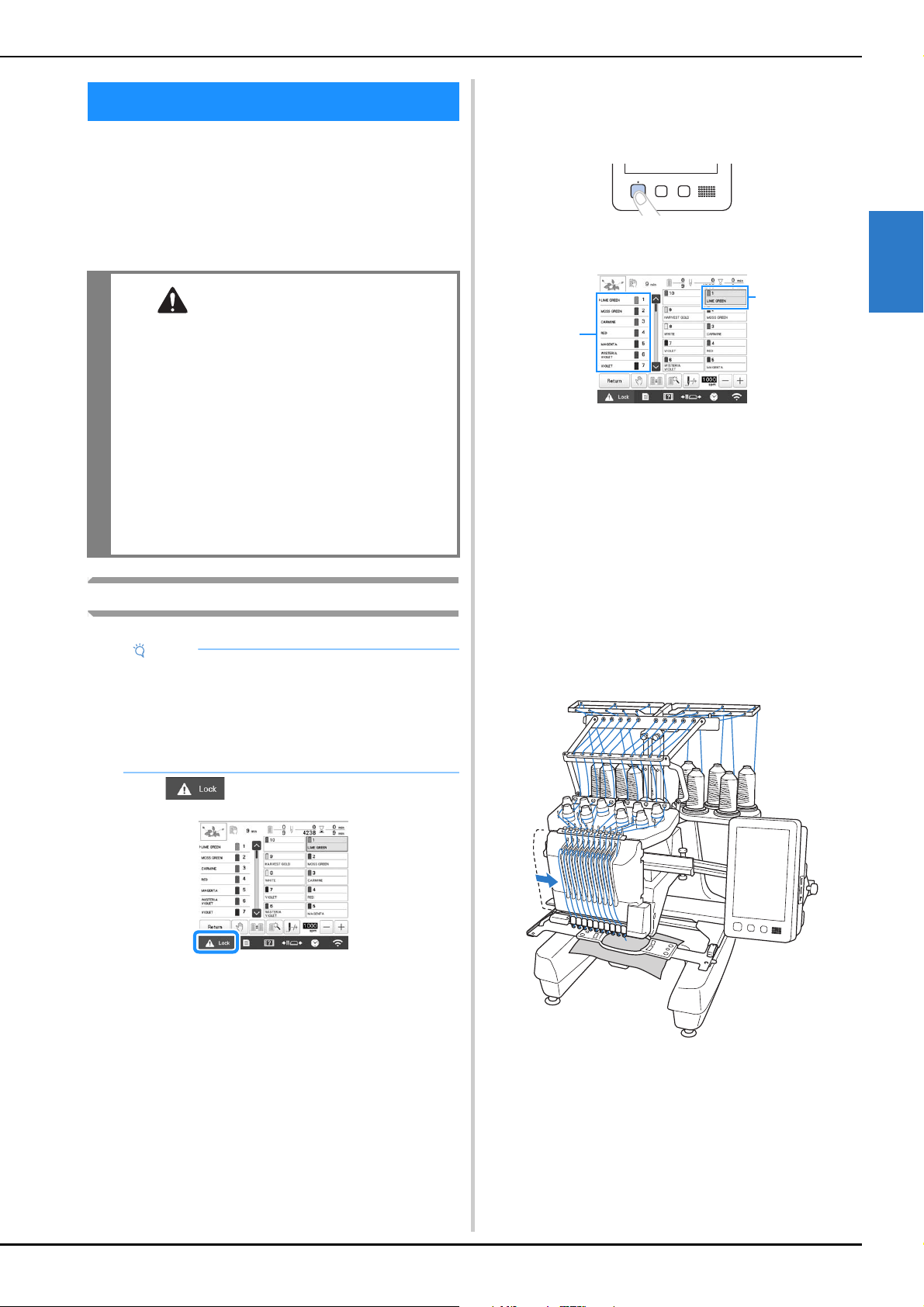
BASIC EMBROIDERY
87
2
Now, the machine is ready to begin embroidering.
When the machine starts embroidering, the presser foot is
automatically lowered, the necessary thread trimming
operations at the beginning of stitching and at the end of
stitching are performed, the threads are changed as
necessary while the embroidery is performed, and the
machine stops when the end of the stitching is reached.
Starting embroidering
a
Touch to unlock the machine.
The “Start/Stop” button changes from lit in red
(locked machine) to flashing in green (unlocked
machine), and the machine is ready to begin
embroidering.
• If the “Start/Stop” button is not pressed within 10
seconds after unlocking the machine, the machine
becomes locked again.
b
Press the “Start/Stop” button.
Press the “Start/Stop” button while it is flashing in green.
If the “Start/Stop” button returns to being lit in red,
perform this procedure again from step
a.
The “Start/Stop” button lights up in green and begins
embroidering the first color.
1 The thread color for the needle bar that is currently being
used for embroidery or will soon be used for embroidery
appears at the top of the thread color sequence display.
The remaining thread colors are listed in embroidering
order, starting from the top.
2 A blue frame appears around the thread information box
of the needle bar currently being selected.
• While the machine is embroidering, the point being
embroidered is indicated by the green cross hairs in
the pattern display area. In addition, the number of
stitches and the time count up.
c
After embroidery of the first color is finished, the
machine automatically stops and trims the thread. The
needle bar case moves to the second color position and
embroidery of the second color begins.
The thread color display in the screen continues to
the second color, and the thread information for the
second needle bar is surrounded by the blue frame.
d
This continues until the last color is embroidered, and
the machine automatically stops.
The embroidering settings screen reappears.
The “Start/Stop” button lights up in red.
• No thread trimming operations at the beginning of
stitching and at the end of stitching are necessary.
PERFORMING THE EMBROIDERY
CAUTION
• For safety reasons, the machine must not be
left unattended while it is embroidering.
• While the machine is in operation, pay special
attention to the needle location. In addition,
keep your hands away from all moving parts
such as the needle, needle bar case, thread
take-up lever and carriage, otherwise injuries
may result.
• When embroidering overlapping stitches, it is
difficult for the needle to penetrate the fabric,
possibly resulting in the needle bending or
breaking.
Note
• Make sure that there are no objects within the
moving area of the embroidery frame. If the
embroidery frame hits another object, the pattern
may become misaligned.
• When embroidering large pieces of fabric, make
sure that the fabric is not caught in the carriage.
1
2
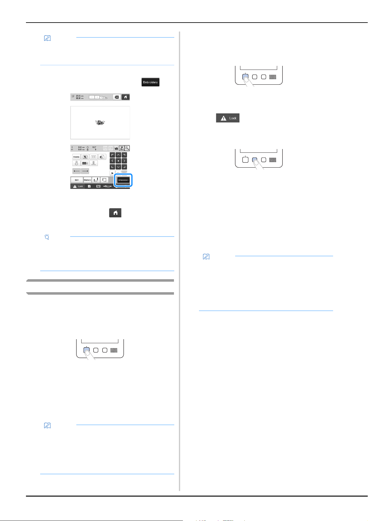
88
■ Continuing embroidering
To embroider the same pattern again, touch .
The embroidering screen appears so the same pattern
can be embroidered again.
To select a new pattern, touch .
The pattern type selection screen appears.
Stopping embroidering
The machine can be stopped during embroidering.
■ Temporarily pausing
a
Press the “Start/Stop” button.
The machine stops and the “Start/Stop” button lights
up in red.
• Embroidering can also be stopped by touching an
area displaying the pattern.
• The thread is not trimmed.
• To continue embroidering, after checking that the
upper thread is taut, touch the unlock key, and then
press the “Start/Stop” button.
■ Temporarily pausing for extended periods of
time
a
Press the “Start/Stop” button.
The machine stops and the “Start/Stop” button lights
up in red.
• The thread is not trimmed.
b
Touch to unlock the machine.
c
Press the thread trimming button.
The bobbin and upper threads are trimmed.
• Before turning off the machine, be sure to trim the
threads.
d
Set the main power switch to “O” to turn off the
machine.
The display and the “Start/Stop” button indicator go
off.
• Embroidery can resume after the machine is turned on
again. Back up several stitches to overlap the
stitching. (page 97)
■ If the thread breaks while embroidering
If a problem occurs while embroidering, such as if the
thread breaks, the machine stops automatically.
Re-thread the broken thread, back up several stitches, and
then continue embroidering. (page 93)
Memo
• When embroidering a pattern that contains 11 or
more colors, it is necessary to change the thread
spools. (page 91)
Note
• Automatic lock stitch setting can be set so that it is
performed at the beginning of the embroidery,
when starting to embroider after changing thread
colors, and when trimming the thread. (page 71)
Memo
• If the reserve stop key is touched while embroidery
is being performed, the machine stops
embroidering before the next color begins.
(page 119)
• Before starting to embroider, the machine can be
set to stop at any thread color change. (page 119)
Memo
• The machine can be stopped at any time, even
while it is embroidering; however, if the machine is
stopped when the thread color is changed, it is not
necessary to go back through the stitching when
embroidering is continued. The machine can be set
to stop when the thread color is changed.
(page 119)
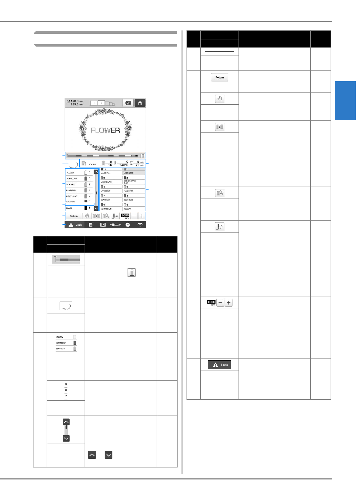
BASIC EMBROIDERY
89
2
Understanding the embroidering screen
From this screen, the total number of thread colors, the
embroidering order and embroidering time can be checked,
the needle bar settings can be specified, and the needle
placement forward or backward can be done. Keys available
in this screen differ when you set [Manual Color Sequence] to
[ON] in settings screen. (page 58)
No.
Display
Function Page
Key Name
1
The embroidering progress is
shown by the red mark in the
indicator. Touch to
display (in the indicator) only
the thread color being
embroidered.
—
Progress bar
2
Shows the part of the pattern
that will be embroidered
with the thread color shown
first in the thread color
sequence display.
—
Region
display
3
Shows the order for the
thread color changes. During
embroidering, this display
scrolls automatically so that
the color of the thread
currently being embroidered
appears at the top.
—
Thread color
sequence
display
Indicates the needle bar
number where the thread
color at the left is assigned.
—
Needle bar
number
The thread color sequence
display shows the first seven
thread colors. To check the
sequence for the eighth and
later thread colors, touch
or , or touch the
scroll bar.
—
Scroll bar
1
2
3
8
6
7
5
4
4
This red line indicator shows
when the thread spools will
need to be changed.
91
Spool change
indicator
5
Quit embroidering and
return to the embroidering
settings screen.
—
Return key
While embroidering, touch
this key for the machine to
stop prior to the next color
beginning.
119
Reserve stop
key
Change the needle bar
settings from the screen
without changing the thread
spools on the machine.
57
Switch spool
key
(Not available
in the
[Manual
Color
Sequence]
mode)
Enable the needle bar
settings to manually be
specified.
120
Temporary
needle bar
settings key
Move the needle forward or
backward through the
stitching. Use this key in the
following situations:
• If the thread breaks or runs
out while embroidering
• To restart embroidering
from the beginning
• To continue embroidering
after the machine was
turned off
93
Forward/
Backward
stitch key
Specify the maximum
embroidery speed.
• Specify a low speed for
thin, thick or heavy
fabrics.
• When using a weak thread
such as metallic thread,
specify an embroidery
speed of 400 spm.
190
Maximum
embroidery
speed key
6
Unlocks the machine so it
can start embroidering
within 10 seconds. When
this key is touched, the
“Start/Stop” button flashes in
green.
87
Unlock key
No.
Display
Function Page
Key Name
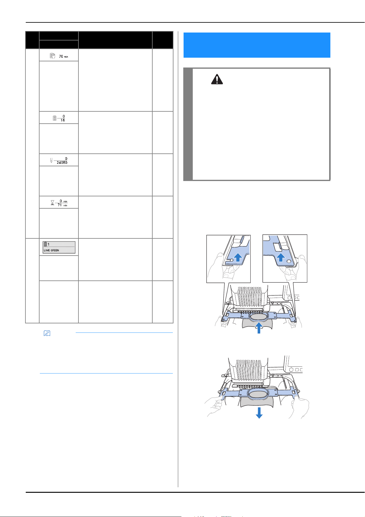
90
a
With both hands, grab the left and right sides of the
arms of the embroidery frame holder, and then slightly
lift up the frame.
The pins on the arms of the embroidery frame holder
should come out of the holes in the sides of embroidery
frame.
b
Pull off the embroidery frame toward you.
Remove the fabric from the frame.
7
Shows the amount of time
until the machine will stop.
When the last thread spool is
being embroidered, the
number appears in red.
If the thread color needs to
be changed, this shows the
time until the thread spool
will need to be changed.
91
Time until the
machine stops
The bottom value shows the
total number of thread colors
in the pattern and the top
value shows the thread color
that is currently being
embroidered.
—
Embroidering
order
The bottom value shows the
total number of stitches in
the pattern and the top value
shows how many stitches
have already been
embroidered.
—
Stitch count
The bottom value shows the
total amount of time required
to embroider the pattern and
the top value shows how
much time has already
passed embroidering.
—
Embroidering
time
8
Move the needle bar position
to the selected needle bar
number. Use when threading
the needle with the
automatic needle-threading
mechanism.
—
Needle bar
key
Thread color
set up display
Shows the color and the
thread color name (number)
for the thread on the needle
bar indicated on the key.
Thread the machine as
indicated here.
81
Memo
• The thread color numbers in the thread color
sequence display and the thread color set up
display can be changed, for example, to the color
name or the thread color number for other brands.
(page 123)
No.
Display
Function Page
Key Name
REMOVING THE EMBROIDERY
FRAME
CAUTION
• When removing the embroidery frame, make
sure that the “Start/Stop” button is lit in red. If
the “Start/Stop” button is flashing in green,
the machine may start embroidering. If the
machine accidentally starts operating, injuries
may result.
• When removing the embroidery frame, be
careful that the embroidery frame does not hit
any other part of the machine.
• Do not lift up the embroidery frame holder
with extreme force, otherwise it may be
damaged.
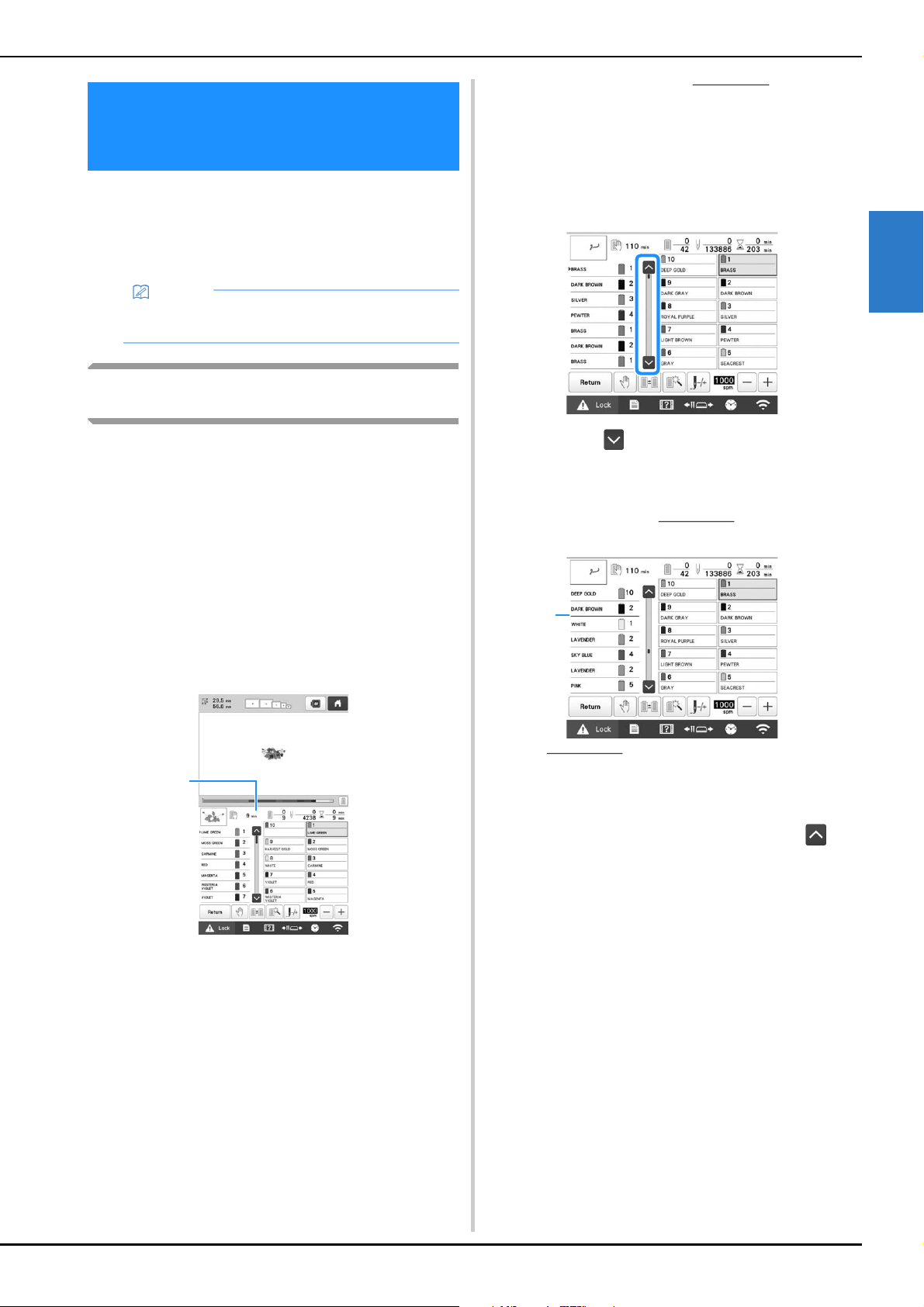
BASIC EMBROIDERY
91
2
When embroidering a pattern that uses 11 or more thread
colors, it is necessary to change the thread spools. When
changing the thread spools, instruction to change the
thread spools will appear with the machine automatically
stopping.
Checking if thread spool changes are
necessary
When selecting a pattern, the number of thread changes can
be viewed; however, which thread colors are used in the
pattern cannot be checked on this screen. Whether or not,
and when, thread spools will need to be changed can be
checked with the following indicators.
■ Time until the machine stops embroidering
This indicator shows the amount of time until the machine
stops embroidering. The machine stops when a spool
change is required, or when the machine is set to be
stopped by other settings.
If the spool change indicator is appears, the machine will
require a spool change. When the time is indicated in red,
it is the last color embroidering before the machine stops.
1 Time until the machine stops
■ Spool change indicator ( )
The spool change indicator in the stitch navigating screen
indicates the number of times that the thread spools will
need to be changed and the amount of time between
changes.
a
Use the scroll bar on the right side of the thread color
sequence display in the embroidering screen.
Each time is touched, the thread color sequence
display scrolls down to the next color. After reaching
the last color in the thread color sequence display,
the first color is selected.
b
Check the position of .
1 indicates when the thread spools will
need to be changed. The thread spools will need to be
changed the number of times that this indicator is
displayed and between the two thread colors at the point
where it is displayed.
c
After checking the desired information, touch or
the top of the scroll bar to return to the first color.
EMBROIDERING A PATTERN
CONTAINING 11 OR MORE
COLORS
Memo
• This function is not available when you set [Manual
Color Sequence] to [ON] in settings screen.
1
1
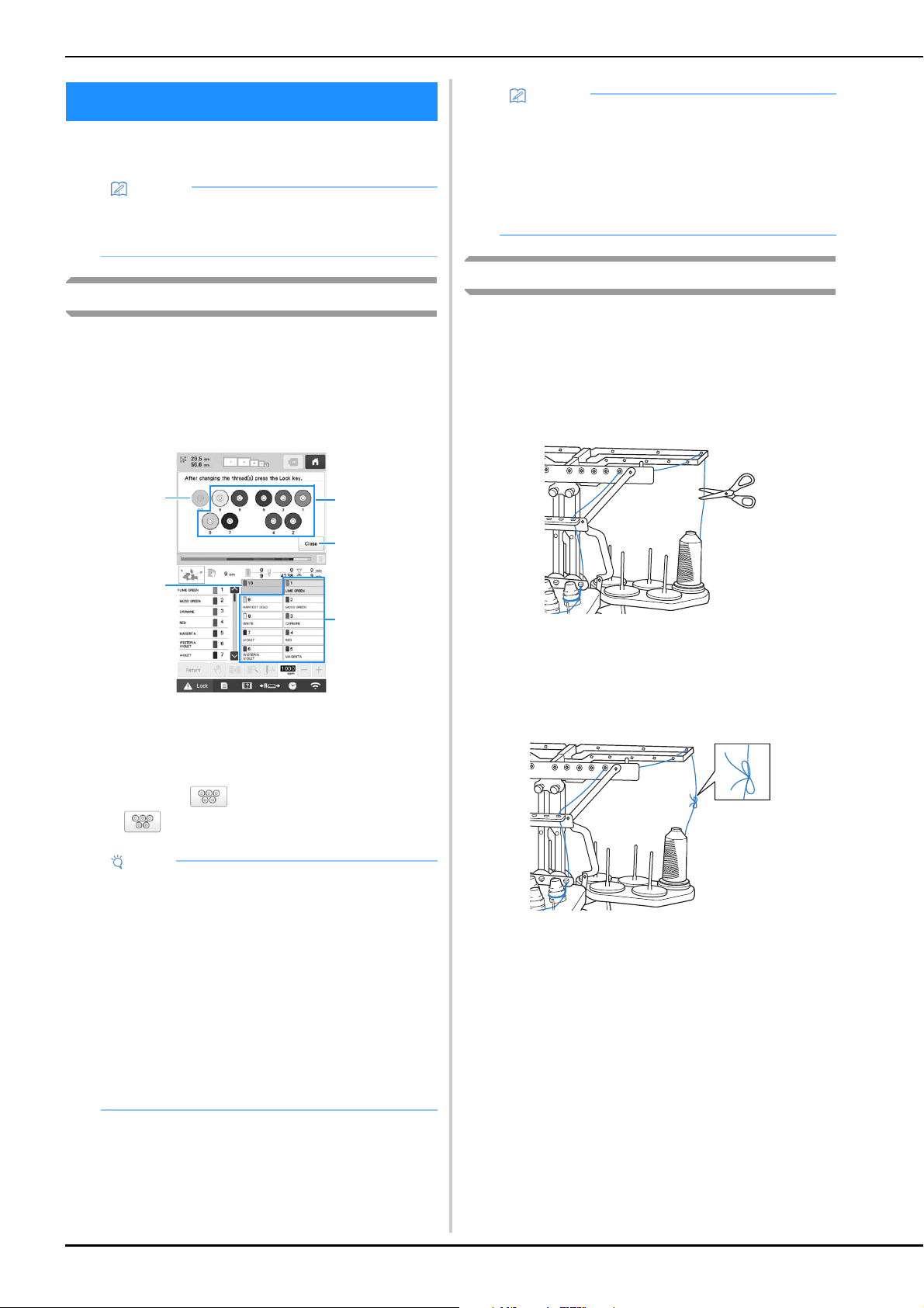
92
This section provides details on the spool thread indicators
in addition to the procedure for easily changing the spools.
About spool thread indicators
When it is necessary to replace the thread spool, the machine
automatically stops embroidering and the screen shown
below appears.
In addition, when a new pattern is selected, the screen shown
below appears. Change the thread spools according to their
new assignments.
1 The thread spools needing to be changed appear in
other than gray.
2 The thread spools needing not to be changed appear in
gray.
3 Minimize the screen indicating that the spools be
changed to . To display the screen again, touch
.
Easily changing the thread spools
When replacing the thread spools, it is necessary to re-thread
the upper thread. However, the thread spools can easily be
changed when replacing a thread spool whose thread is
correctly threaded through the machine.
a
Cut the thread between the thread spool and the
thread guide.
b
Change the thread spool.
c
Tie the end of the thread on the new spool with the end
of the thread remaining from the previous color.
CHANGING THE THREAD SPOOLS
Memo
• This feature is not available if [Manual Color
Sequence] has been set to [ON] in the settings
screen.
Note
• Touch needle bar key to move the needle into the
correct position for threading with the new thread
color. (page 86)
• When the embroidering screen appears, the needle
bar settings are saved.
• If the needle bar settings are saved and the next
pattern that is opened contains thread colors that
are the same as those from the previous pattern,
the same needle bars will be assigned the same
thread colors from the previous pattern.
• If you wish to delete all assigned colors on display,
refer to “To cancel the thread color settings for all
previously stitched design” on page 57.
1
3
1
2
2
Memo
• To use a different thread color than the one that
was specified, use the temporary needle bar
setting key, and then change the thread color
setting. (page 120)
• To minimize changing the thread spools, frequently
used thread colors can be specifically assigned to
certain needle bars. (page 121)
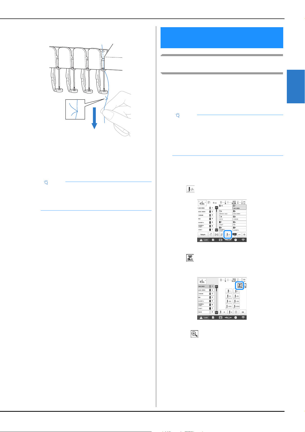
BASIC EMBROIDERY
93
2
d
Pull out the old thread just after the needle bar thread
guide.
Continue pulling the thread until the knot is below the
needle. Cut the knot.
e
Use the automatic needle-threading mechanism to
thread the needle with the new thread. (page 85)
This completes the changing of the thread spool.
If the thread breaks or the bobbin thread
runs out while embroidering
If the thread breaks or the bobbin thread runs out while
embroidering, the machine will automatically stop. Since
some stitches may be embroidered with only one thread, go
back through the stitching to a point prior to the stoppage
before continuing embroidering.
■ If the upper thread breaks
a
Re-thread the upper thread. (page 82)
b
Touch .
The stitch navigating screen appears.
c
Touch to check the needle drop point on the LCD
screen.
The camera view window appears.
• Touch to zoom up the camera view twice the
size of normal view.
Note
• When pulling out the thread, do not pull the knot
through the eye of the needle. If the knot is pulled
through the eye of the needle, the needle may be
damaged.
ADJUSTING WHILE
EMBROIDERING
Note
• If [Thread Sensor] is set to [OFF], the machine does
not stop until embroidering is finished. Normally,
the [Thread Sensor] should be set to [ON].
• Be careful when going back or forward through the
stitching since the embroidery frame moves at the
same time.
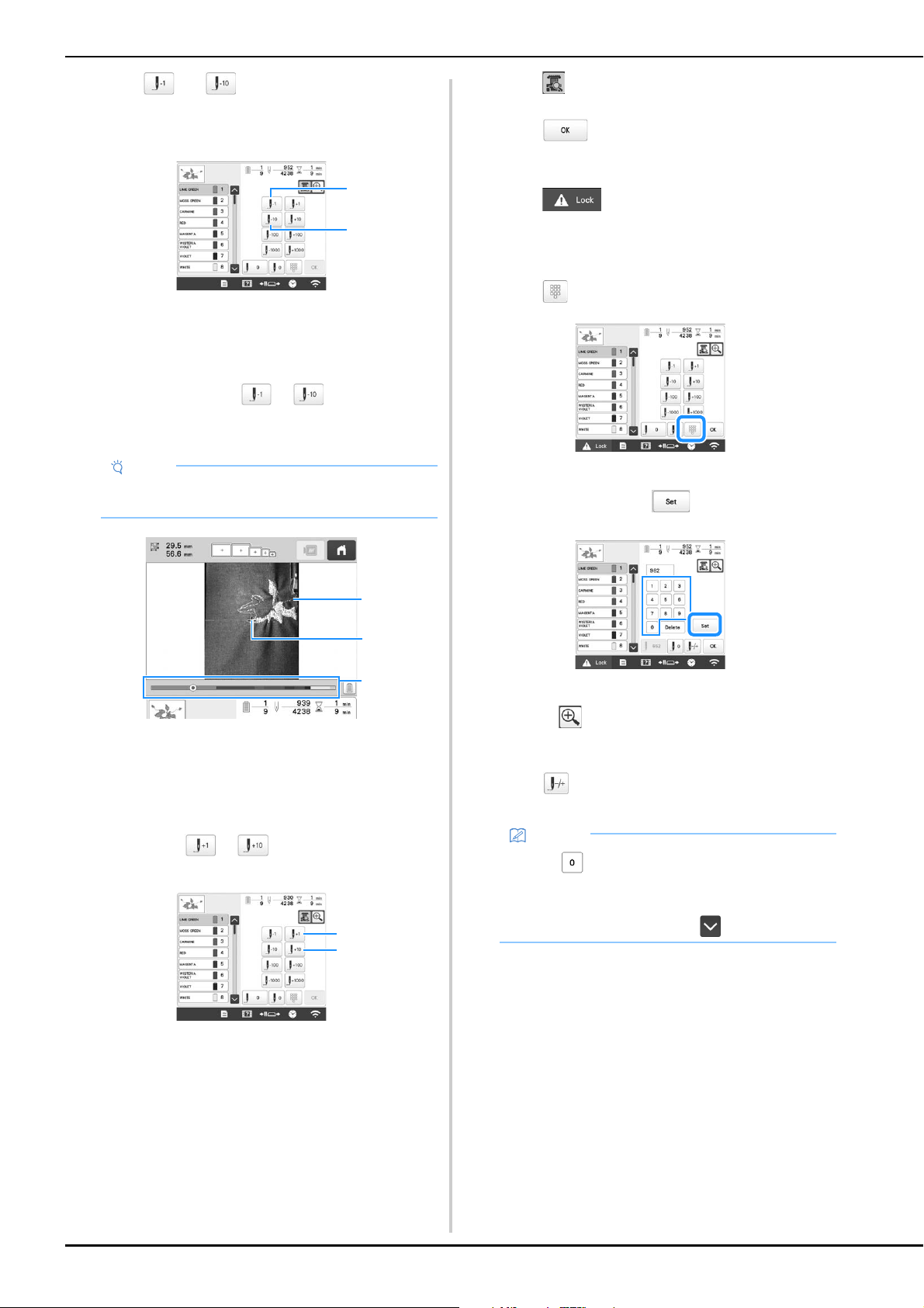
94
d
Touch and to go back through the stitching
to a point where stitches have already been
embroidered.
1 Each touch of this key moves one stitch back through
the stitching.
2 Each touch of this key moves ten stitches back through
the stitching.
As you move to the area where your design was last
stitched, by touching the or , the embroidery
frame will move, allowing you to place the cross mark
directly on the last stitch shown.
1 Stitch line
2 Cross mark
3 Embroidery progress bar
You can also touch the specific point of the embroidery
progress bar to move the stitch count to the desired point.
If the needle bar is moved back too far through the
stitching, touch or to go forward through the
stitching.
1 Each touch of this key moves one stitch forward through
the stitching.
2 Each touch of this key moves ten stitches forward
through the stitching.
e
Touch .
f
Touch .
The embroidering screen appears again.
g
Touch , and then press the “Start/Stop”
button to continue embroidering.
■ Specifying a stitch number
a
Touch .
b
Use the number keys to enter the desired stitch
number, and then touch .
The embroidery frame moves to the specified stitch.
When is touched in this screen to enlarge the
display, a stitch number can be specified with the
number keys.
c
Touch to return to the previous screen, and then
continue with step
e on page 94.
Note
• It is recommended to stitch over the top of the last
two or three stitches for complete coverage.
1
2
1
2
3
1
2
Memo
• Touch to reset the stitch number and
embroider from the first stitch.
• To specify the last stitch number, select the last
thread color, and then touch .
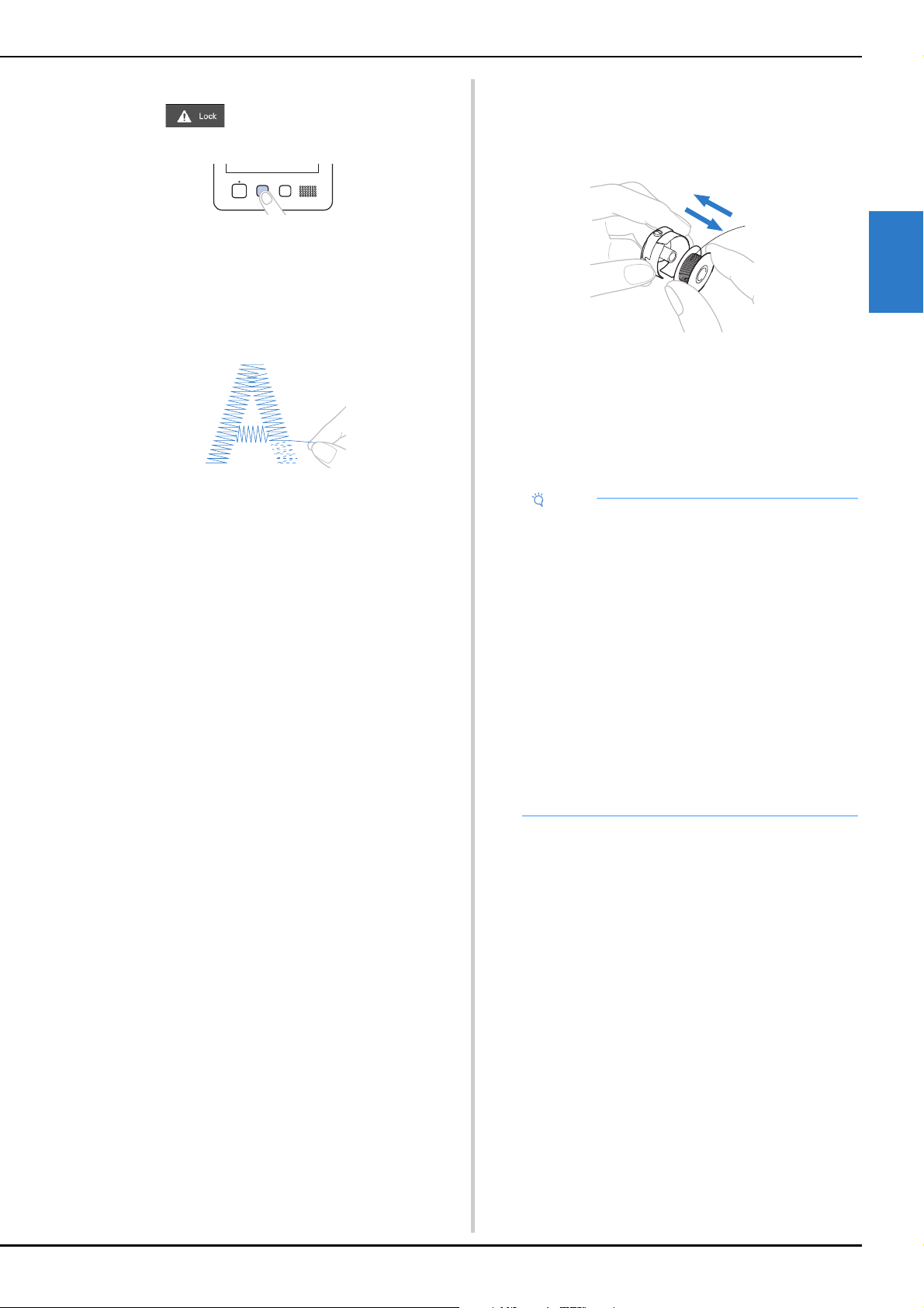
BASIC EMBROIDERY
95
2
■ If the bobbin thread breaks or runs out
a
Touch , and then press the thread trimming
button.
The upper thread is trimmed.
• If the bobbin thread breaks or runs out, also trim the
upper thread.
b
Remove the stitches embroidered only with the upper
thread.
Pull the trimmed end of the upper thread.
• If the stitches cannot be cleanly removed, trim the
thread with scissors.
■ If the bobbin thread ran out, replace the
bobbin at this point in the procedure.
c
Replace the bobbin with a bobbin wound with bobbin
thread. (page 33)
• If the hook cover can be opened, replace the bobbin
without removing the embroidery frame from the
machine.
• If the machine bed is hidden, for example, with a bag-
shaped piece of fabric, or if the hook cover cannot be
opened, temporarily remove the embroidery frame.
(page 90) After replacing the bobbin, re-attach the
embroidery frame. (page 64)
d
Go back through the stitching in the same way as that
described in step
b through g of “If the upper
thread breaks” on page 93, and then continue
embroidering.
Note
If the embroidery frame is removed before
embroidering of the pattern is finished, take caution,
otherwise the pattern may become misaligned.
• Do not apply extreme pressure to the framed fabric
and cause it to become loose.
• When removing and re-attaching the embroidery
frame, do not allow the frame to hit the carriage or
the presser foot.
If the carriage is hit and moves, turn the machine
off, then on again. The correct frame position at the
time that the machine was stopped is stored in the
machine’s memory, and the embroidery frame is
returned to the correct position.
• When the embroidery frame is re-attached, make
sure that the pins on the left and right arms of the
embroidery frame holder securely fit into the holes
in the handles on the embroidery frame.
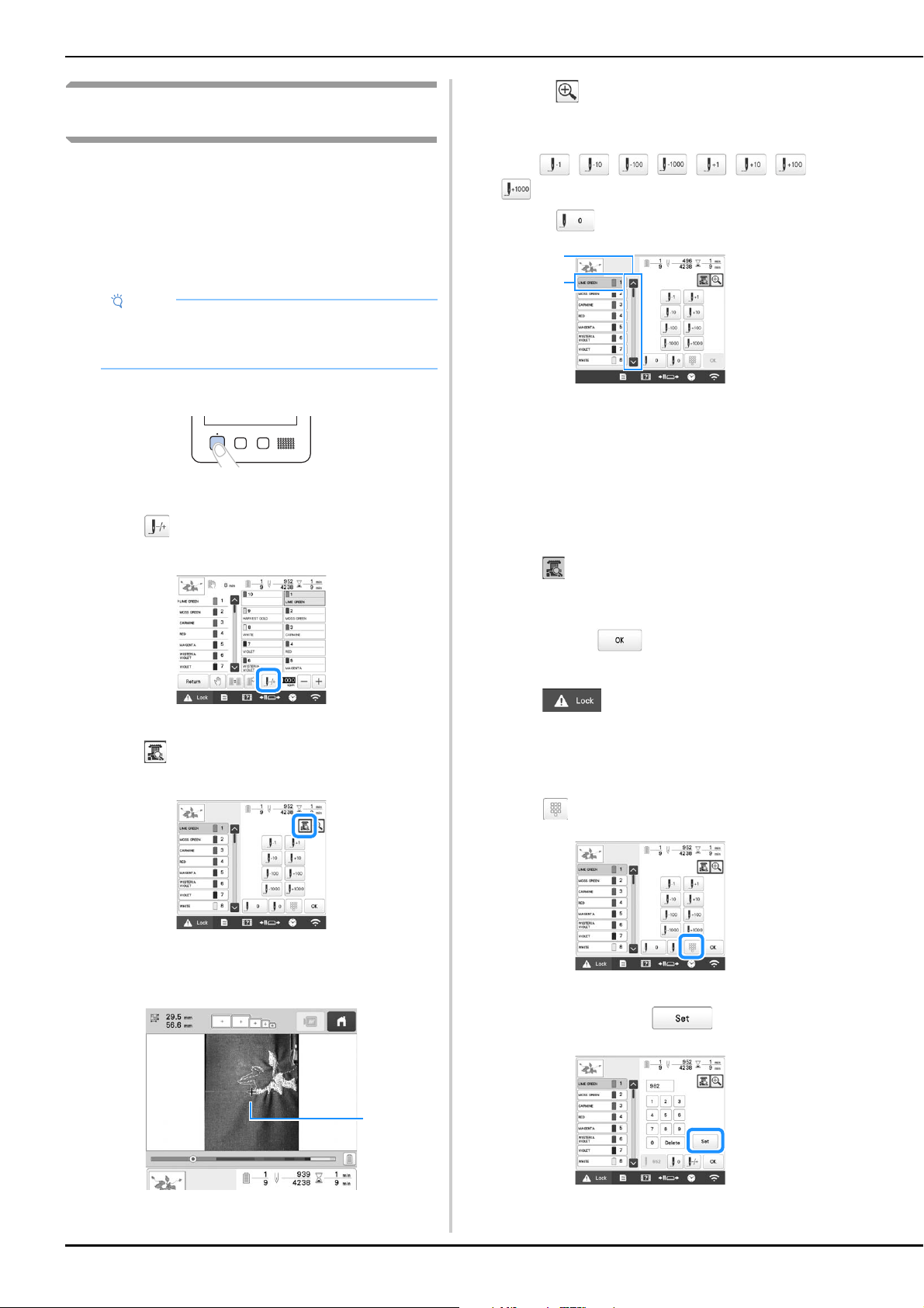
96
Embroidering from the beginning or middle
of the pattern
If you wish to restart embroidering from the beginning, for
example, if trial embroidery was performed and an incorrect
thread tension was used or if the wrong thread color was
used, restart the embroidering using the forward/backward
stitch key. In addition, you can go forward or back through
the stitching by thread color or by stitch to start stitching at
any position of the pattern.
a
Press the “Start/Stop” button to stop the machine.
• If necessary, trim and remove the embroidered
stitches.
b
Touch .
The stitch navigating screen appears.
c
Touch to check the needle drop point on the LCD
screen.
The camera view window appears and the cross
mark in the camera view indicates the needle drop
point.
1 Needle drop point
• Touch to zoom up the camera view twice the
size of normal view.
d
Use the scroll bar to select the thread color, and then
touch , , , , , , and
to select the specific stitch.
• Touch to embroider from the beginning.
1 The stitch from where embroidering is to begin can also
be specified by using the scroll bar.
2 The thread color at the top of the thread color sequence
display is the color of the area currently selected.
Touch this area to specify the stitch from where
embroidering is to begin.
The needle bar case moves and the current needle
bar moves to the embroidering position, and then the
embroidery frame moves and current needle position
is indicated.
e
Touch .
f
After selecting the stitch from where embroidering is
to begin, touch .
The embroidering screen appears again.
g
Touch , and then press the “Start/Stop”
button to begin embroidering.
Embroidering begins from the specified point.
■ Specifying a stitch number
a
Touch .
b
Use the number keys to enter the desired stitch
number, and then touch .
The embroidery frame moves to the specified stitch.
Note
• Be careful when going back or forward through the
stitching since the embroidery frame moves at the
same time.
1
2
1
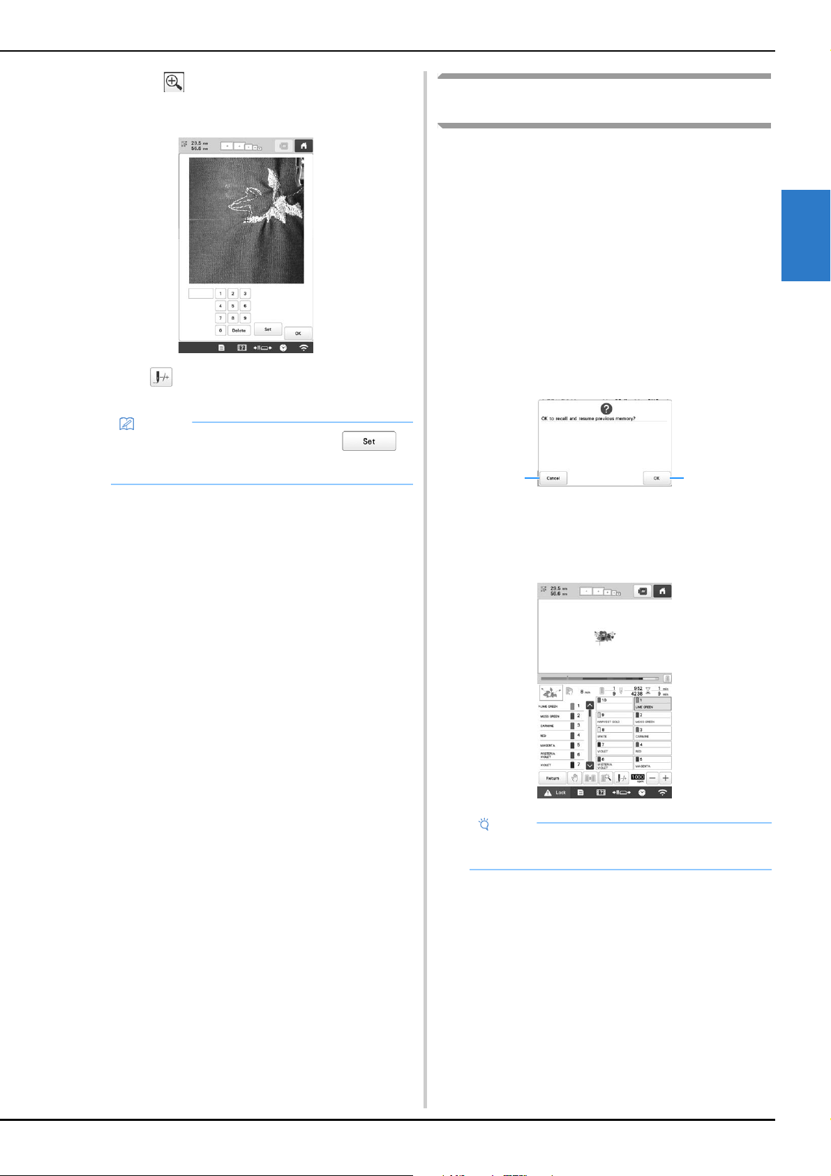
BASIC EMBROIDERY
97
2
When is touched in this screen to enlarge the
display, a stitch number can be specified with the
number keys.
c
Touch to return to the previous screen, and then
continue with step
e on page 96.
Resume embroidering after turning off the
machine
In either of the following cases, the remaining stitches of the
embroidery are stored in the machine’s memory.
• If the machine’s power switch is pressed to turn off
before stopping embroidering.
Cut the thread before the machine’s main power
switch is turned off, otherwise the thread may be
pulled or may catch when the carriage returns to its
initial position after the machine is turned on again.
• If the machine was accidentally turned off, for
example, due to a power outage, while it was
embroidering.
The remainder of the embroidery can be performed
when the machine is turned on again; however, some
of the stitches that were already embroidered may be
embroidered again.
1 Cancel embroidering and display the pattern type
selection screen to select a new pattern.
2 Continue embroidering.
The embroidering screen displayed before the
machine was turned off appears.
Memo
• If no stitch number was entered when is
touched, embroidering will begin from the first
stitch.
Note
• You may need to advance or reverse through the
stitches to get to the correct needle drop position.
21

98
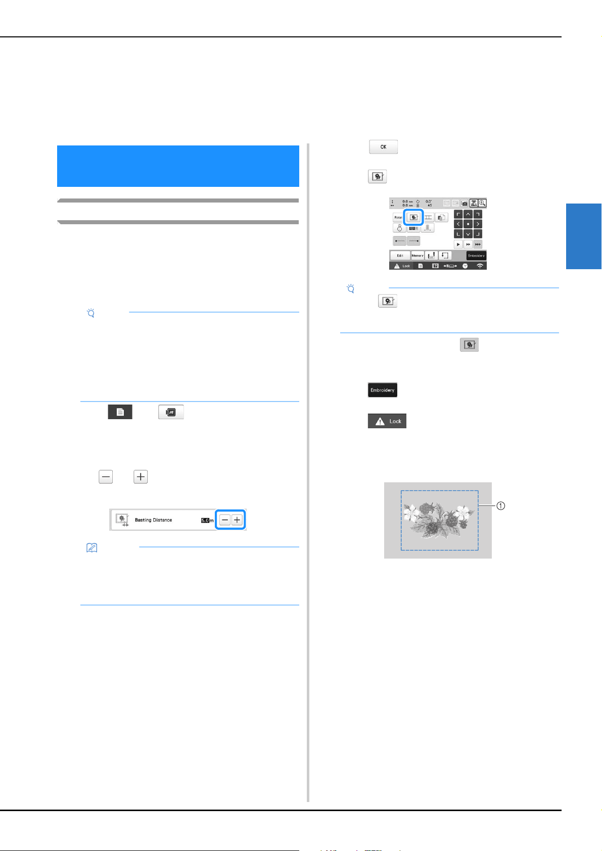
ADVANCED EMBROIDERY
99
3
Basting embroidery
Before embroidering, basting stitches can be embroidered
along the outline of the pattern. This is useful for
embroidering fabric that cannot have stabilizer material
affixed with an iron or adhesive. By stitching stabilizer
material to the fabric, shrinkage of the stitching or misaligned
pattern can be minimized.
a
Touch , then .
The embroidery settings screen appears.
b
Locate [Basting Distance].
c
Use and to specify the distance from the
pattern to the basting stitching.
d
Touch to return to the embroidering settings
screen.
e
Touch to select the basting setting.
• To cancel the setting, touch .
Basting is added to the beginning of the
embroidering order.
f
Touch to continue to the embroidering screen.
g
Touch , and then press the “Start/Stop”
button to begin embroidering.
h
When embroidering is finished, remove the basting
stitching.
1 Basting stitching
Chapter 3
ADVANCED
EMBROIDERY
VARIOUS EMBROIDERY
FUNCTIONS
Note
• It is recommended to finish combining and editing
the pattern before selecting the basting setting. If
the pattern is edited after selecting the basting
setting, the basting and pattern may become
misaligned, and the basting under the pattern may
be difficult to remove after embroidering is
complete.
Memo
• The higher the setting, the farther the basting is
from the pattern.
• The setting remains selected even if the machine is
turned off.
Note
• When is touched, the pattern is moved to the
center. After selecting the basting setting, move the
pattern to the desired position.
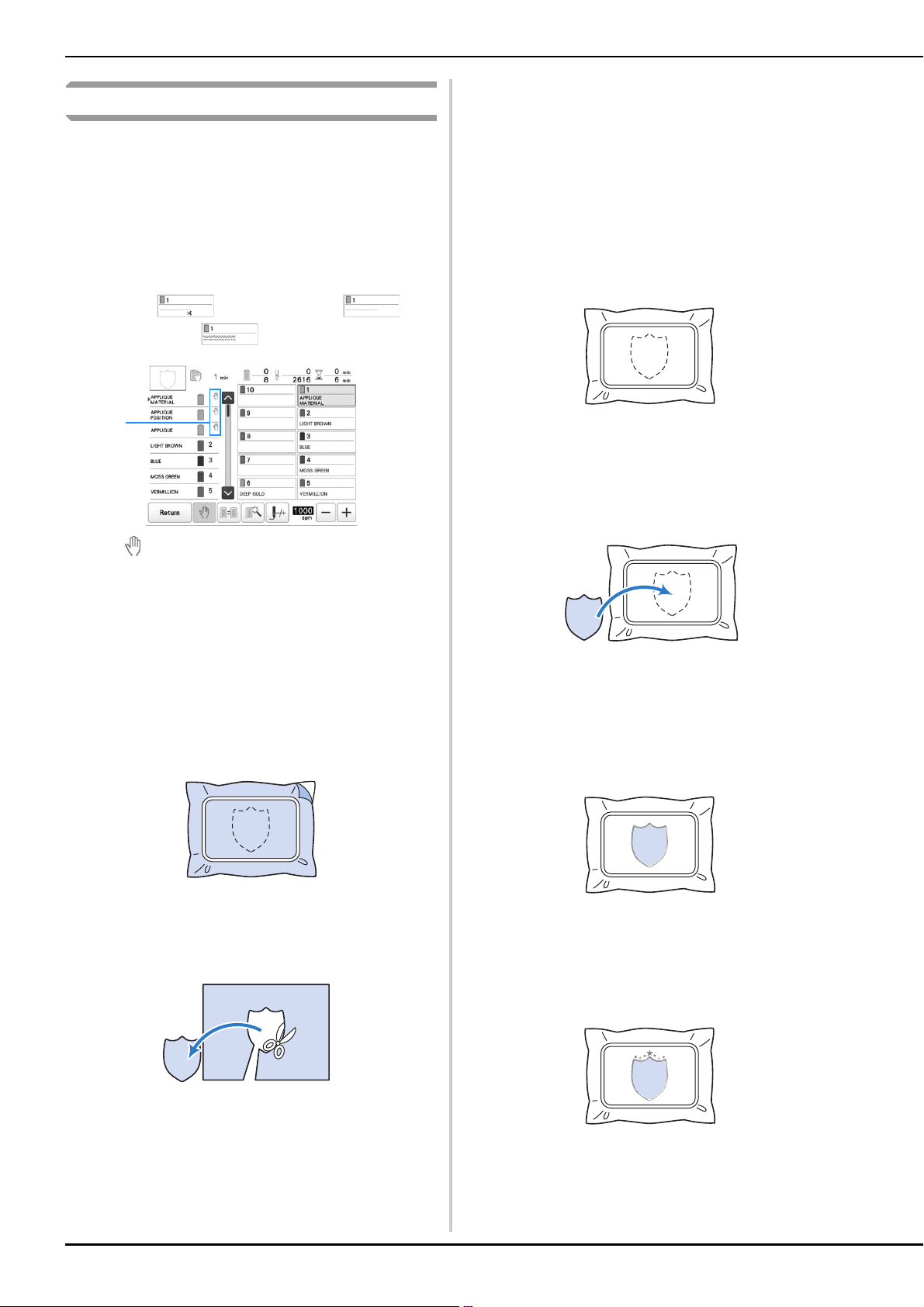
100
Embroidering appliqué patterns
Some of the built-in embroidery patterns can be used for
embroidering appliqués. Follow the procedures described
below to embroider appliqués using the patterns with
[APPLIQUE MATERIAL], [APPLIQUE POSITION] or
[APPLIQUE] in the region display at the top of the thread
color sequence display.
[APPLIQUE MATERIAL], [APPLIQUE POSITION] and
[APPLIQUE] are assigned to a specific needle bar number.
*Depending on the thread color display setting, the display
may appear as (Appliqué Material),
(Appliqué Position) or (Appliqué).
1 appears in the screen at places where the machine
is stopped.
■ Procedure for embroidering appliqués
a
Place stabilizer on the back of the appliqué fabric/
material.
b
Frame the fabric for the appliqué (from step a) in the
embroidery frame, and then embroider an [APPLIQUE
MATERIAL] pattern. The line that indicates where the
appliqué will be cut out is embroidered, and then the
machine stops.
c
Remove the appliqué fabric from the embroidery
frame, and then carefully cut along the embroidered
cut line.
• If the appliqué is cut out along the inside of the
embroidered cut line, the appliqué may not be
correctly attached to the fabric. Therefore, carefully
cut out the appliqué along the embroidered cut line. If
this step is not performed carefully, the appliqué will
not be cleanly finished. In addition, carefully remove
any excess threads.
d
Frame the base fabric or garment in the embroidery
frame, and then embroider an “APPLIQUE POSITION”
pattern. The appliqué position is embroidered, and
then the machine stops.
e
Lightly apply fabric glue or spray adhesive to the back
of the appliqué piece that was cut out, and then attach
the appliqué piece to the base fabric at the position
embroidered using the [APPLIQUE POSITION] pattern
in step
d.
• If an iron-on stabilizer is used to attach the appliqué
piece to the base fabric, iron the pieces together
without removing the base fabric from the embroidery
frame.
f
After attaching the appliqué piece, embroider an
[APPLIQUE] pattern. The appliqué is finished.
• Depending on the pattern, an [APPLIQUE] pattern
may not be available. In this case, embroider the
appliqué using thread in the color of a part of the
embroidery.
g
Finish stitching the embroidery.
1
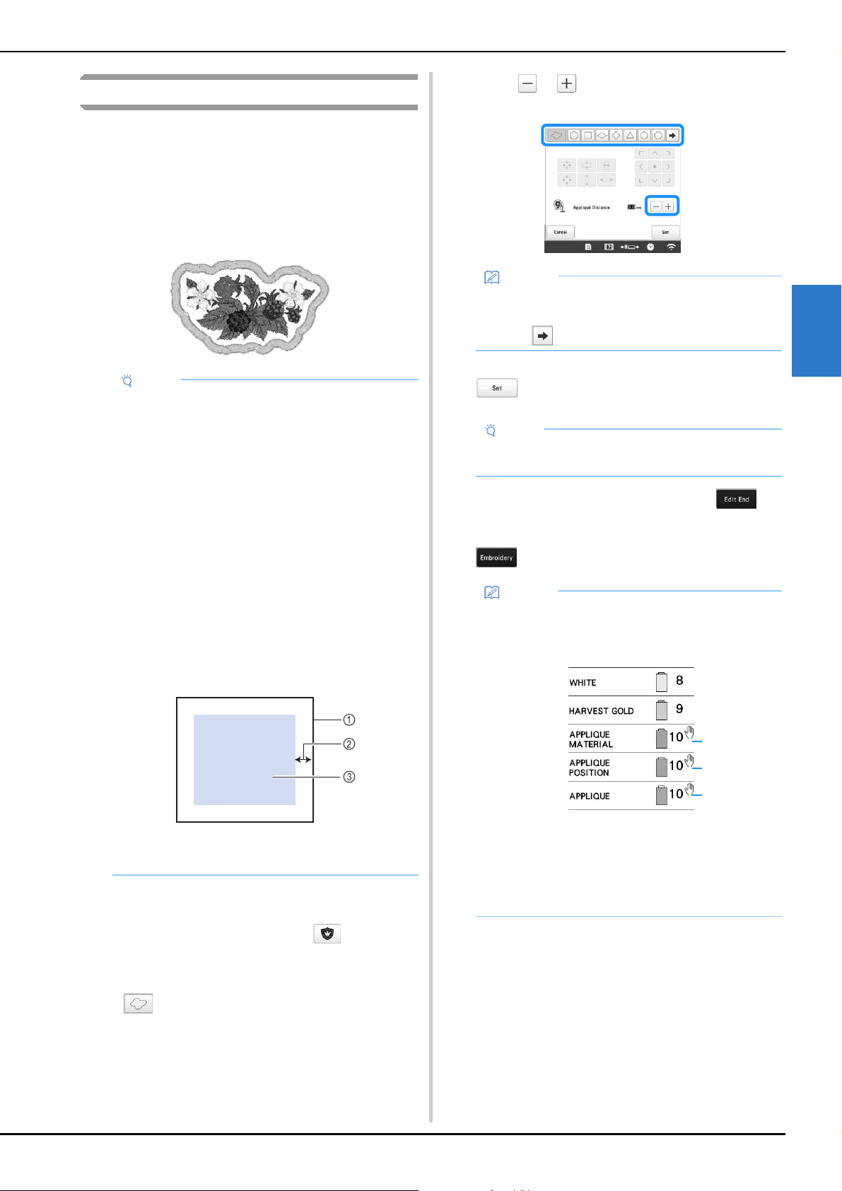
ADVANCED EMBROIDERY
101
3
Creating an appliqué piece
Appliqué pieces can be created from the built-in patterns and
patterns from other sources. This is convenient for fabrics that
cannot be embroidered or when you wish to attach an
appliqué to a garment.
■ Creating an appliqué piece
The following pattern will be used to create an appliqué
piece.
a
Select the pattern to be used for the appliqué.
b
In the pattern editing screen, touch .
c
Select the outline.
If is selected, an outline can be created most
closely fits the edges of the pattern.
Use or to specify the distance between the
pattern and the appliqué outline.
d
Check the preview in the screen, and then touch
.
e
After specifying the various settings, touch .
f
Specify the embroidering settings, and then touch
to continue to the embroidering screen.
g
Fuse or stick a piece of stabilizer to the back of the felt
or denim fabric to be used as the appliqué piece.
h
Hoop the appliqué fabric in the embroidery frame,
attach the embroidery frame to the machine, and then
start embroidering.
i
After the cutting line [APPLIQUE MATERIAL] is
embroidered, stop the machine and remove the
appliqué material from the embroidery frame.
Note
• Felt or denim fabrics are recommended to make
the appliqué piece. Depending on the pattern and
fabric used, lighter weight fabrics may cause the
stitching to appear smaller.
• For best results, be sure to use stabilizer material
for embroidering.
• Select a frame that matches the pattern size.
Frame options are displayed on the LCD screen.
• Finish combining and editing the pattern before
selecting the appliqué setting. If the pattern is
edited after selecting the appliqué setting, the
appliqué stitching and pattern may become
misaligned.
• Since an outline is added, the pattern for an
appliqué piece (when the appliqué setting is
selected) will be larger than the original pattern.
First, adjust the size and position of the pattern as
shown below.
1 Embroidering area
2 Approx. 10 mm (3/8 inch)
3 Pattern size
Memo
• If a frame pattern is selected for the outline, the
frame pattern can be enlarged, reduced or moved.
• Touch to select a different outline pattern.
Note
• At this time, the pattern and outline will be
grouped.
Memo
• Three steps are added to the embroidering order:
appliqué cutting line, position of pattern placement
on the garment, and appliqué stitching.
1 Cutting line for appliqué
2 Position of pattern placement on garment
3 Appliqué stitching
• We recommend using thread for the cutting line
[APPLIQUE MATERIAL] that is closest to the color
of the fabric.
1
2
3
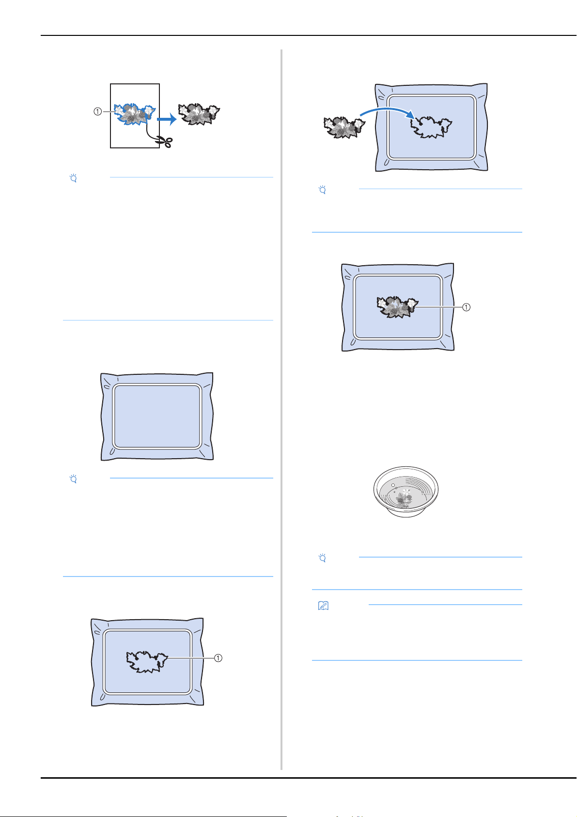
102
j
Carefully cut along the stitching. After cutting,
carefully remove all of the cutting line thread.
1 Cutting line for appliqué
k
Use two layers of adhesive water-soluble stabilizer
material with their sticky sides together, and then hoop
them in the embroidery frame.
l
Embroider the placement line for the appliqué position
[APPLIQUE POSITION].
1 Pattern placement line
m
Lightly apply glue or spray adhesive, and paste the
appliqué piece so that it aligns with the placement line.
n
Embroider the outline [APPLIQUE].
1 Outline of appliqué piece
o
After embroidering is finished, remove the stabilizer
material from the embroidery frame.
p
Use scissors to cut the excess water-soluble stabilizer
from outside the appliqué outline.
q
Soak the appliqué piece in water to dissolve the water-
soluble stabilizer.
r
Dry the appliqué piece, and then iron it if necessary.
Note
• Depending on the pattern density and fabric used,
there may be shrinking of the pattern or the
appliqué may be misaligned with the placement
line. We recommend cutting slightly outside of the
cutting line.
• When using patterns that are vertically and
horizontally symmetrical, use a chalk pencil to
indicate the pattern orientation before cutting it out.
• Carefully cut out the pattern on the outline you just
embroidered. Do not cut inside the cutting line,
otherwise the appliqué fabric will not be caught by
the appliqué stitch.
Note
• If water-soluble stabilizer is used, it is not
necessary to remove the stabilizer material after
embroidering the appliqué outline. To reduce
shrinkage of the pattern, we recommend using
water-soluble stabilizer.
• Put together two layers of water-soluble stabilizer,
otherwise the stabilizer material may tear during
embroidering.
Note
• Before pasting the appliqué piece down, make sure
the appliqué piece is positioned correctly within the
placement line.
Note
• Do not apply a strong force when ironing,
otherwise the stitching may be damaged.
Memo
• The outline is embroidered using satin stitching.
• Some glue may get onto the presser foot, needle,
and needle plate at this time. Finish embroidering
the appliqué pattern, and then clean off the glue.
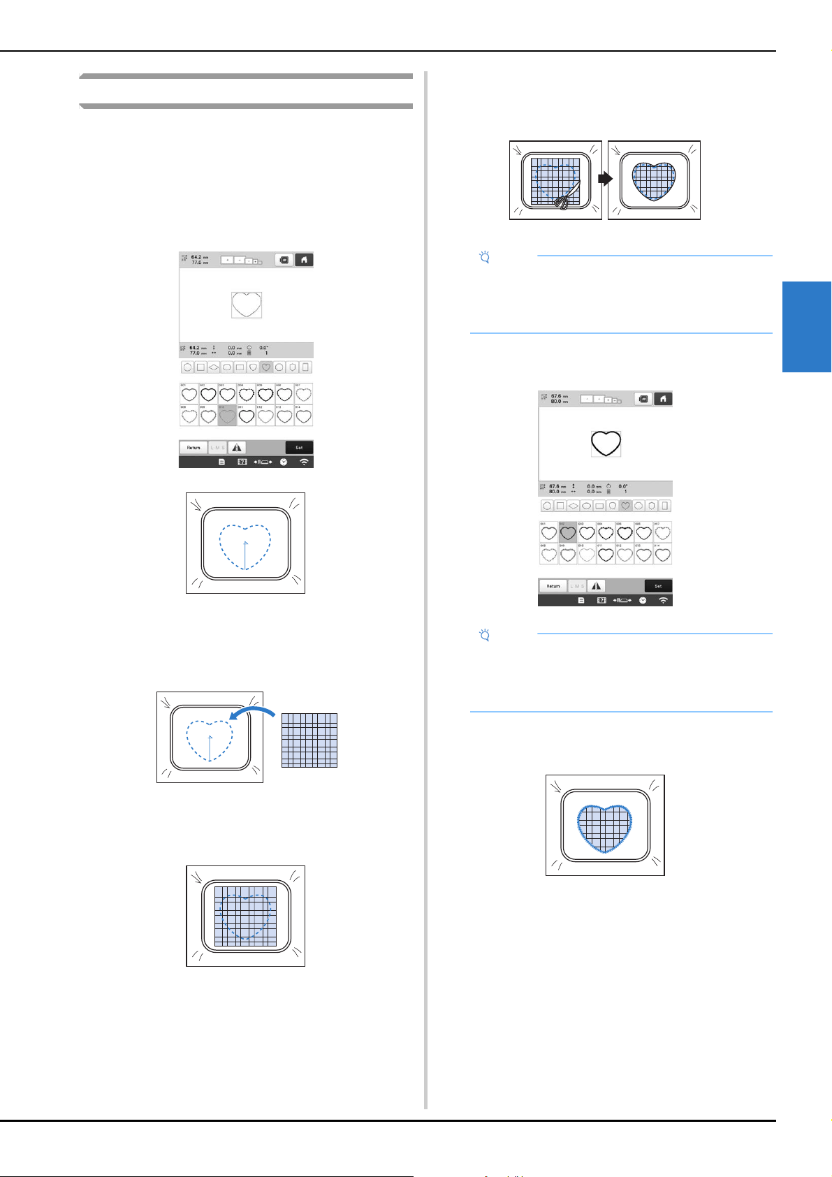
ADVANCED EMBROIDERY
103
3
Using a frame pattern to create appliqués
With this method, there is no need to change the fabric in the
embroidery frame. The appliqué can be created by
embroidering two frame patterns of the same size and
shape—one embroidered with straight stitches and the other
embroidered with satin stitches.
a
Select a frame pattern embroidered with straight
stitches and embroider onto the base fabric.
b
Place the appliqué fabric over the embroidery stitched
in step
a. Make sure that the appliqué fabric is larger
than the embroidered area.
c
Embroider over the appliqué fabric using the same
frame pattern.
• Be sure to stop the machine before the cross at the
center is embroidered.
d
Remove the embroidery frame from the machine, and
then cut off the excess appliqué fabric along the
outside of the stitching.
e
Select the satin-stitched frame pattern with the same
shape.
f
Attach the embroidery frame removed in step d, and
then finish embroidering the appliqué.
Note
• Leave the fabric in the embroidery frame when
cutting off the excess appliqué fabric. In addition,
do not apply extreme pressure to the framed fabric,
otherwise the fabric could become loose.
Note
• If the size or embroidering position of the straight-
stitched frame pattern is changed, be sure to
change the size or embroidering position of the
satin-stitched frame pattern in the same way.
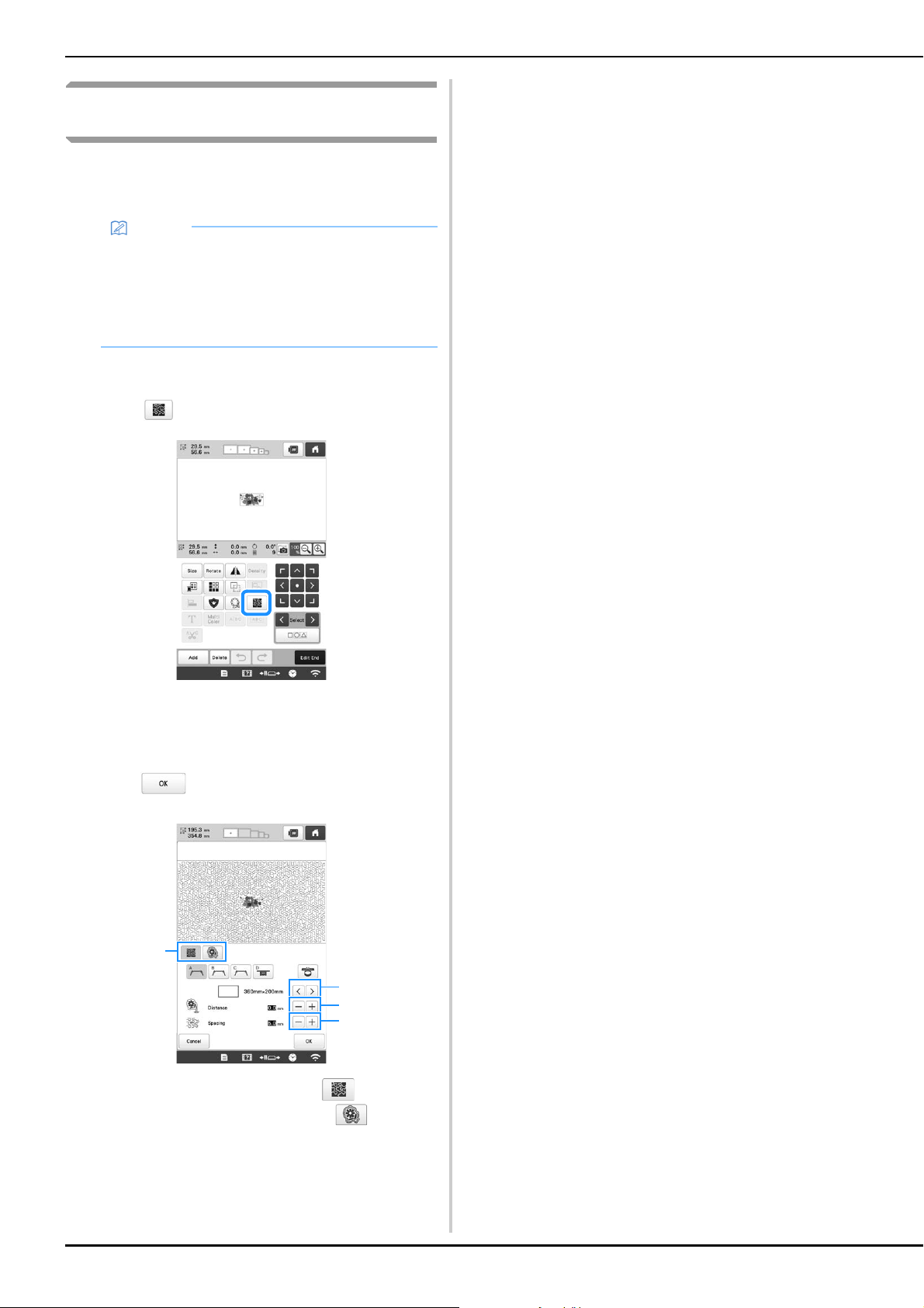
104
Creating stippling or echo patterns
automatically
Stippling or echo quilting patterns can be created around the
machine’s built-in patterns or original embroidery data
without using My Design Center.
a
Select the pattern that stippling will be added around.
b
Touch in the embroidery edit screen.
Stippling is automatically applied around the
selected pattern.
To select multiple patterns, refer to page 42.
c
After specifying the stitch settings for the stippling,
touch .
1 To create a stippling pattern, touch . When you
create an echo quilting pattern, touch .
2 If an embroidery frame size is selected, the stippling is
added within the area of the selected frame size. If the
pattern is larger than the selected frame size, the area
indicating the frame size will appear in gray.
3 Specify the distance from the outline of the pattern to the
stippling.
4 Specify the spacing for the stippling.
Memo
• If this simple stippling operation is used with
batting sandwiched between two layers of fabric,
the embroidery pattern and stippling may become
misaligned. For details on quilting, refer to
“Decorative stitching around a pattern in
embroidery (a quilting function)” on page 170.
2
1
3
4
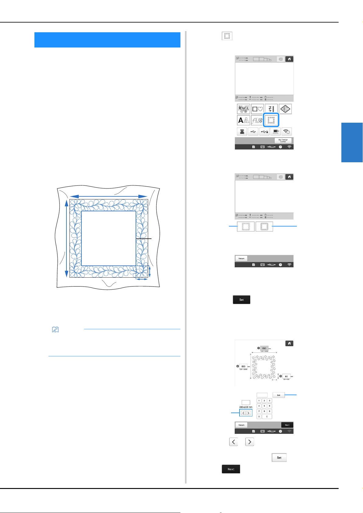
ADVANCED EMBROIDERY
105
3
By rehooping the fabric to embroider connecting patterns,
a quilting border of 3 m × 3 m (approx. 118 inches × 118
inches) can be created.
■ Using the camera
When embroidering a quilting border, use the built-in
camera to display a camera image of the fabric in order to
align the pattern.
Specify the appropriate image settings in advance.
(page 73)
• Better camera image results can be achieved with the
appropriate settings.
■ Creating quilting border data
a
With a chalk pencil, mark the fabric with the inner
outline of the quilting border to be embroidered.
Measure the size of the quilting border.
1 Inner outline (used for positioning)
2 Width
3 Height
4 Width of quilting border
b
Touch .
c
Select the category for the number of thread colors.
1 Single color pattern
2 Multi-color pattern
d
Select the pattern that you want to embroider, and
then touch .
e
Specify the size of embroidery frame to be used and
the size of the quilting border.
1 Touch or to select the embroidery frame size.
2 Specify the width (1), height (2) and quilting border
width (3), and then touch after each entry.
f
Touch .
QUILTING BORDERS
Memo
• Be sure to cut the fabric with an excess of about 10
cm (4 inches) so that its edges extend from the
embroidery frame.
a
d
b
c
21
2
1
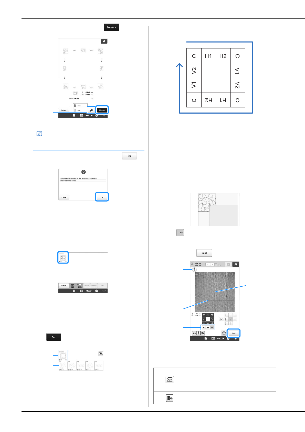
106
g
Check the pattern, and then touch to save it.
1 The thread colors can be changed.
h
After the following message appears, touch .
A screen appears so that a pattern from the
machine’s memory can be selected.
■ Embroidering a quilting border
a
In the screen for selecting a pattern from the machine’s
memory, select the saved data.
A thumbnail of the entire quilting border pattern and
a thumbnail of each split pattern appear.
b
For this example, since we will embroider the quilting
border according to the on-screen instructions, select
the thumbnail for the entire quilting border, and then
touch .
1 Embroider the quilting border pattern according to the
on-screen instructions. The number in the lower-left
corner indicates the total number of split patterns in the
quilting border.
2 To embroider by visually aligning the patterns, touch
each split pattern.
You can check where and how many times the pattern
will be embroidered with the codes written on each key.
C: Corner
V1: First pattern of the vertical side
V2: Second pattern of the vertical side
H1: First pattern of the horizontal side
H2: Second pattern of the horizontal side
c
Hoop the fabric in the embroidery frame so that the
upper-left corner of the quilting border pattern is in the
embroidering area, and then attach the embroidery
frame to the machine.
d
Align the position for the pattern in the upper-left
corner.
With highlighted, use the move pattern keys to
align the inside corner of the reference lines previously
drawn on the fabric with the inner corner of the pattern,
and then touch .
1 Display the on-screen instructions again.
2 Inner corner of the pattern
3 Corner of the reference lines drawn on the fabric
4 Select the speed for moving the embroidery frame.
Memo
• The edges of the pattern may be shortened when
they are displayed.
1
1
2
Move the embroidery frame to the position
where the fabric can be rehooped easily.
For details, refer to “Rehooping the fabric”
on page 108.
Save the camera image to the external
device.
1
4
3
2
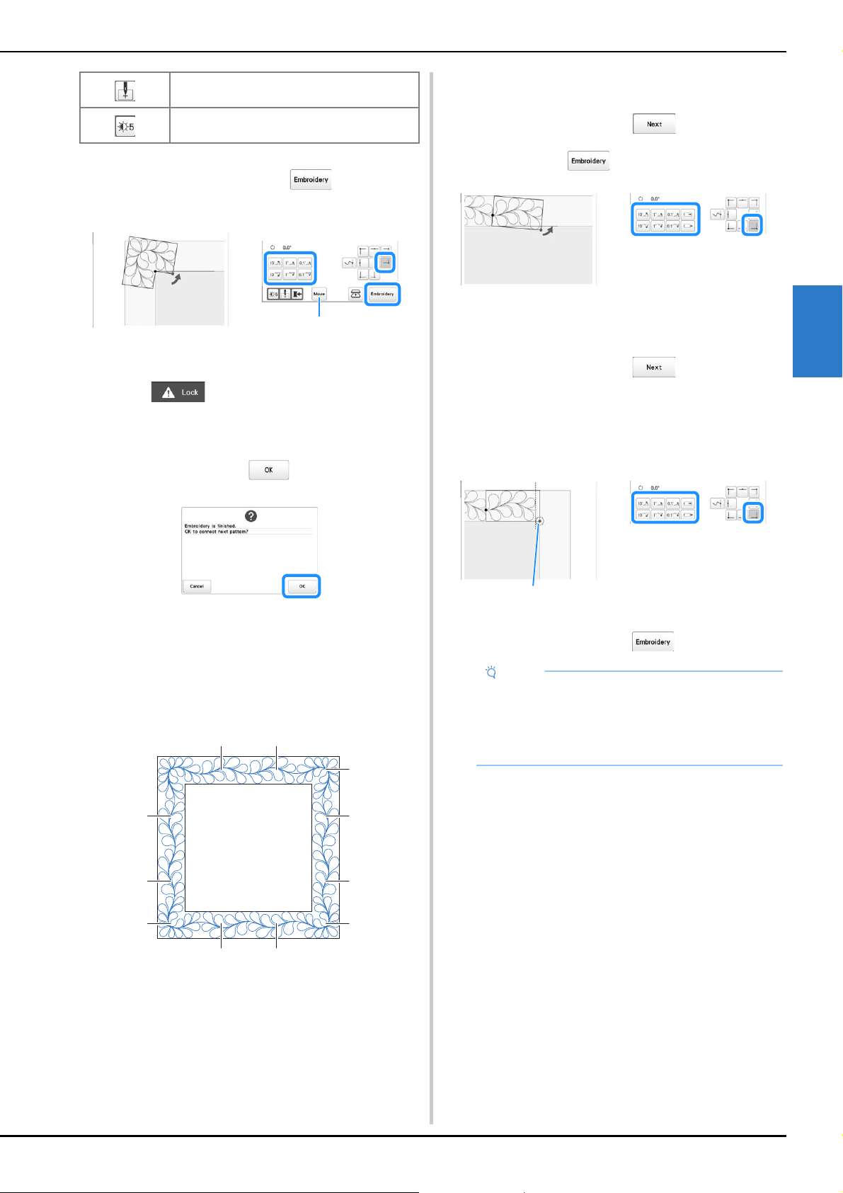
ADVANCED EMBROIDERY
107
3
e
Rotate the pattern so that it is aligned with the chalk
reference lines, and then touch to display the
embroidering screen.
1 The screen where the pattern can be moved appears
again.
f
Touch to unlock the machine, and then
press the “Start/Stop” button to embroider the first
pattern.
g
When embroidering is finished and the following
message appears, touch .
The next pattern to be embroidered appears.
h
Position each pattern and embroider it according to
the on-screen instructions.
You will be prompted to align the starting point, rotate
the design, and rehoop the fabric when necessary. For
details, refer to “Rehooping the fabric” on page 108.
1 When embroidering the edge pattern
If the fabric has just been rehooped, use the move pattern keys
to align the start point on the screen with the end point of the
previous pattern, and then touch .
Then, rotate the pattern to align the corner with the reference
line, and then touch .
2 When embroidering the pattern immediately before a
corner
If the fabric has just been rehooped, use the move pattern keys
to align the start point on the screen with the end point of the
previous pattern, and then touch .
Then, align the point of the pattern (inner corner of the next
pattern to be embroidered) with the corner of the reference
lines. If the pattern is not angled correctly, rotate it. If the length
of the pattern does not match, enlarge or reduce the pattern so
that the point of the pattern is at the corner of the reference
lines.
* Inner corner of next pattern to be embroidered
After making adjustments, touch .
Select whether or not to display the needle
drop point
Each touch of this key changes the
brightness of the camera image.
1
a b
b a
c
a
d
a
b
c
c
Note
• For the accurate start point, turn the handwheel
toward the LCD panel to lower the needle. Check
the needle drop point, and then turn the handwheel
again until the needle is raised to its highest
position.
*
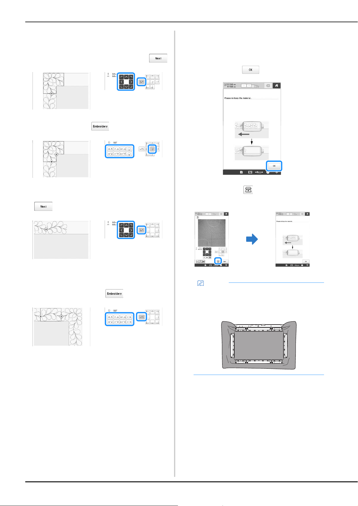
108
3 When embroidering the corner pattern
Rotate the fabric 90 degrees counterclockwise, rehoop it, and
then attach the embroidery frame to the machine. Use the
move pattern keys to align the start point on the screen with
the end point of the previous pattern, and then touch .
Then, align the inner corner of the pattern with the corner of the
reference lines, and touch .
4 When embroidering the last edge pattern
Use the move pattern keys to align the start point on the screen
with the end point of the previous pattern, and then touch
.
Then, align the end point of the last pattern with the start point
of the first pattern. If the pattern is not angled correctly, rotate
it. If the length of the pattern does not match, enlarge or reduce
the pattern.
After making adjustments, touch .
■ Rehooping the fabric
If necessary, the on-screen instructions to rehoop the
fabric appears. While the on-screen instructions are being
displayed, the embroidery frame moves to the position
where the fabric can be rehooped easily. Rehoop the
fabric, and then touch .
If you want to rehoop the fabric while the camera image is
being displayed, touch . After the on-screen
instructions appear, rehoop the fabric.
Memo
• Using the optional magnetic sash frame, the fabric
can be easily rehooped without removing the frame
from the machine. For details, refer to the manual
included with magnetic sash frame.
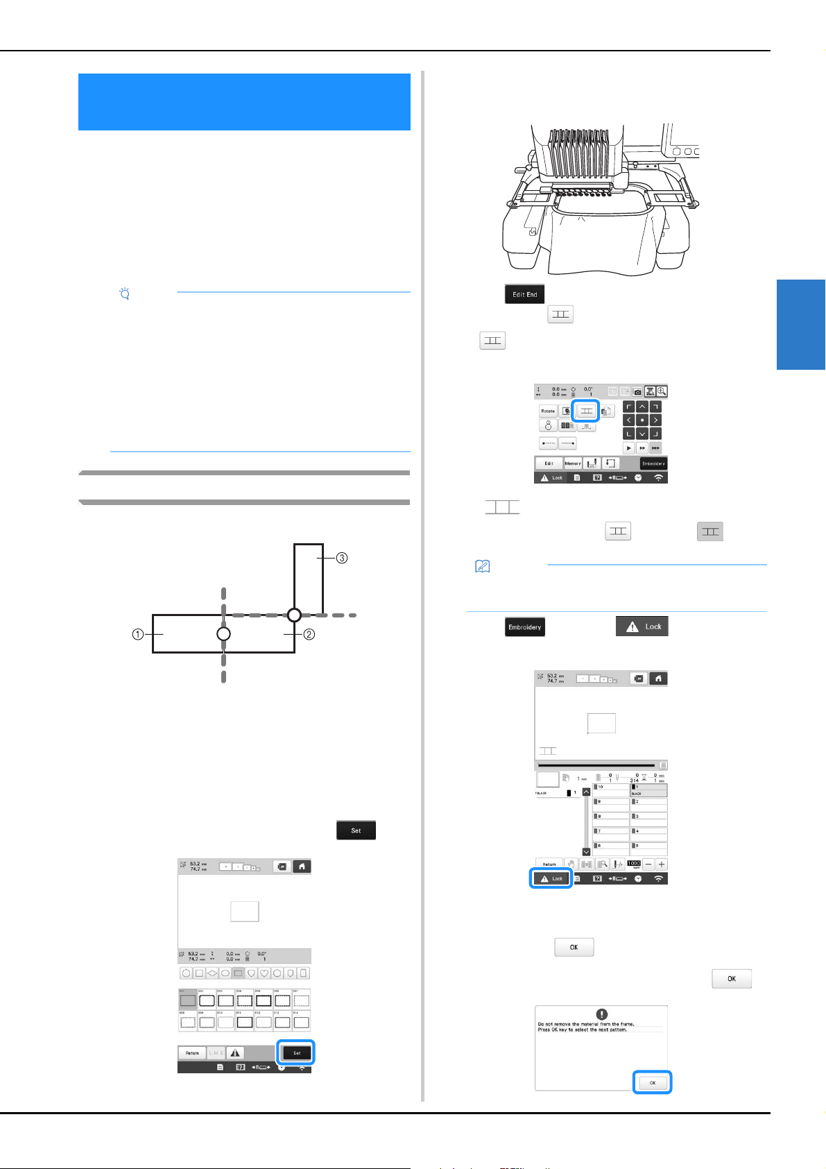
ADVANCED EMBROIDERY
109
3
Instead of using thread marks, the camera can be used to
connect patterns.
An area of 330 mm × 170 mm (13 inches × 6-1/2 inches)
can be embroidered when the camera is used to connect
patterns. Select the appropriate frame depending on the
size of the embroidery. We recommend using the extra-
large embroidery frame (360 mm × 200 mm (14 inches ×
7-7/8 inches)) when using the camera to connect patterns.
Connecting three patterns
Example:
1 Pattern A
2 Pattern B
3 Pattern C
a
Specify the appropriate image settings in advance.
(page 73)
• Better scanning results can be achieved with the
appropriate settings.
b
Select the first pattern A, and then touch .
c
Hoop fabric in the extra-large embroidery frame (360
mm × 200 mm (14 inches × 7 7/8 inches)), and then
attach the frame to the machine.
d
Touch to display the embroidering settings
screen. Touch .
• needs to be selected in order to continue
connecting patterns.
appears at the bottom left side of pattern
display area, and then changes to .
e
Touch , then touch and then press
the “Start/Stop” button to embroider the first pattern.
f
After embroidering of the first pattern is finished, the
message to confirm to connect the next pattern
appears. Touch .
g
When the following message appears, touch .
USING THE CAMERA TO CONNECT
PATTERNS
Note
• When installing the embroidery frame (small) (60
mm × 40 mm (2-3/8 inches × 1-1/2 inches)), cap
frames, cylinder frame, sleeve frame, clamp
frames, name frame or the round frames, you
cannot connect patterns using this function.
• Split (large-size) patterns created with PE-DESIGN
version 7 or later cannot be used with this function.
• You cannot connect patterns using this function
while the machine is set to the Link mode.
Memo
• A pattern cannot be saved in the machine’s memory
while patterns are being connected.
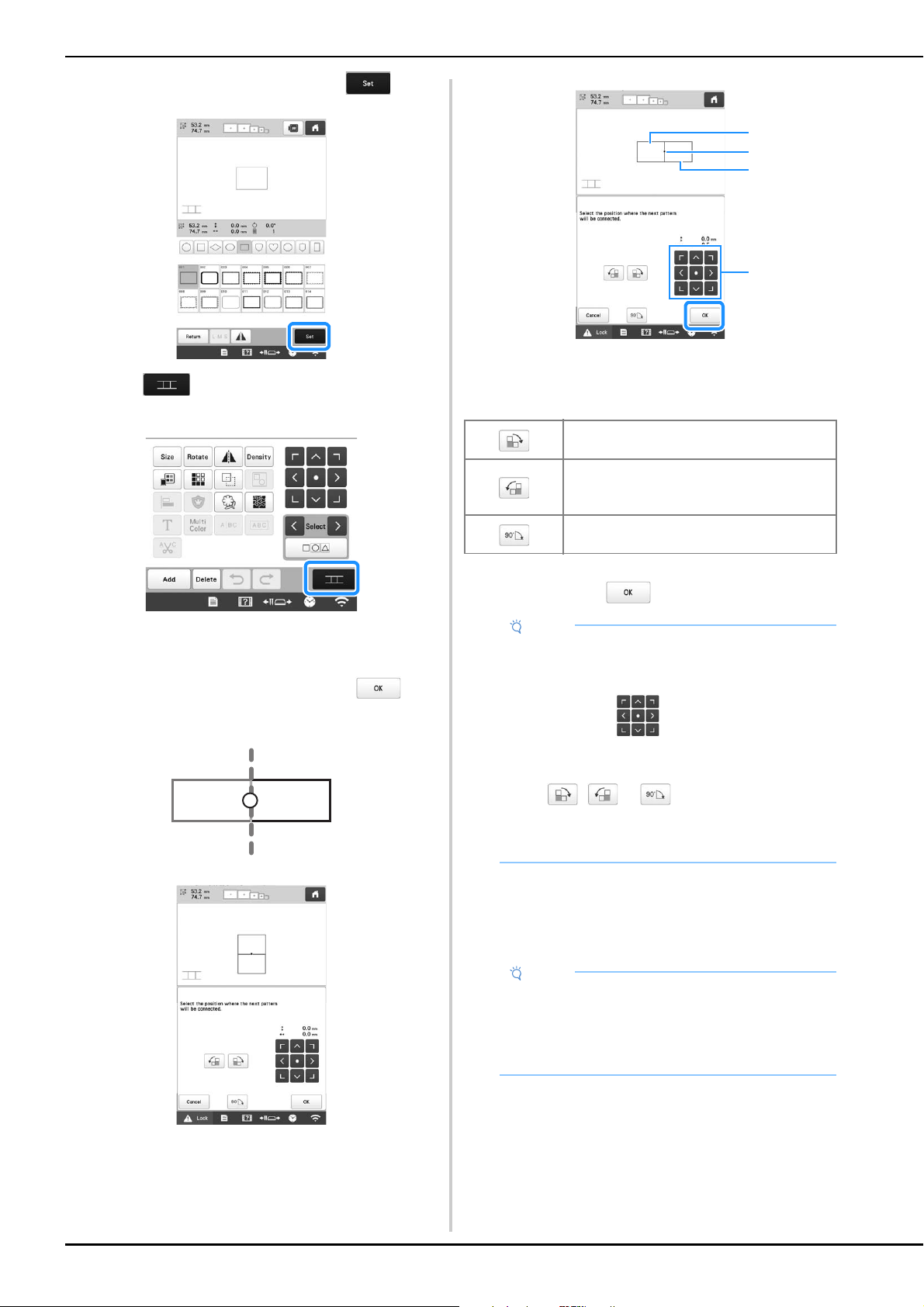
110
h
Select the second pattern B, then touch .
i
Touch , and then select how the pattern will be
connected.
The pattern connection setting screen appears.
j
Touch the position for the second pattern will be
connected on the screen, and then touch . In
this example, touch the right side of the first pattern.
• You can adjust the position of the second pattern,
using the keys described below.
1 Touch the connecting area
2 Second pattern B
3 First pattern A
4 Move the second pattern.
Message appears on screen and carriage will move
after touching .
k
Prepare two embroidery positioning stickers.
We will follow the on-screen instructions to affix these
two stickers to the fabric so that the positioning marks
can be detected by the camera.
Rotate the second pattern in a clockwise
arc referring the first pattern as a center.
Rotate the second pattern in a
counterclockwise arc referring the first
pattern as a center.
Rotate the second pattern 90 degrees in a
clockwise arc.
Note
• The second pattern will be automatically
connected to the first pattern without adjustment.
Change the position of the second pattern
manually using .
• The position of the second pattern can be moved
using your finger or the included touch pen.
• Use , or if you want to align the
pattern to the corner of the center of the first
pattern, when changing the pattern's connecting
position.
Note
• Use the positioning stickers included with this
product or purchase replacement stickers (refer to
“Optional accessories” on page 14) from your
Brother dealer. If any other sticker is used, the
camera may not recognize it.
3
2
1
4
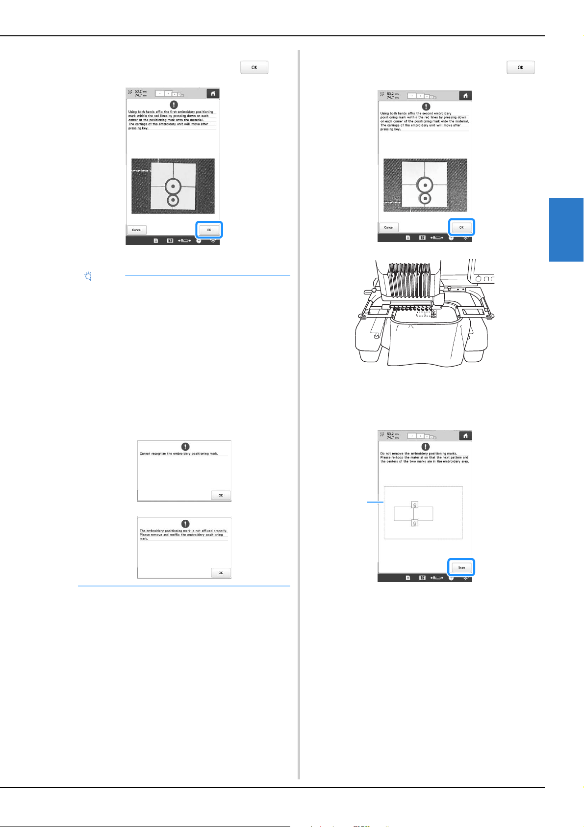
ADVANCED EMBROIDERY
111
3
l
Affix the first embroidery positioning sticker onto the
fabric as shown on machine. Then, touch .
The camera detects the first positioning sticker.
m
Affix the second embroidery positioning sticker onto
the fabric as shown on machine. Then, touch .
The camera detects the second positioning sticker.
n
After the two positioning stickers have been detected,
the following message appears.
1 Embroidering area
Note
• Use new positioning stickers. If a sticker is reused,
it may easily peel off. If the sticker peels off during
this procedure, the patterns cannot be connected.
Start the project again with new fabric and
stabilizer.
• Using fingers apply pressure to the corners of the
positioning sticker to firmly affix it to the fabric. If
the sticker is not firmly attached, the camera may
incorrectly detect the sticker.
• If any of the following messages appear, reattach
the positioning sticker in the correct position. Make
sure that the sticker is affixed with the large circle
at the top.
1
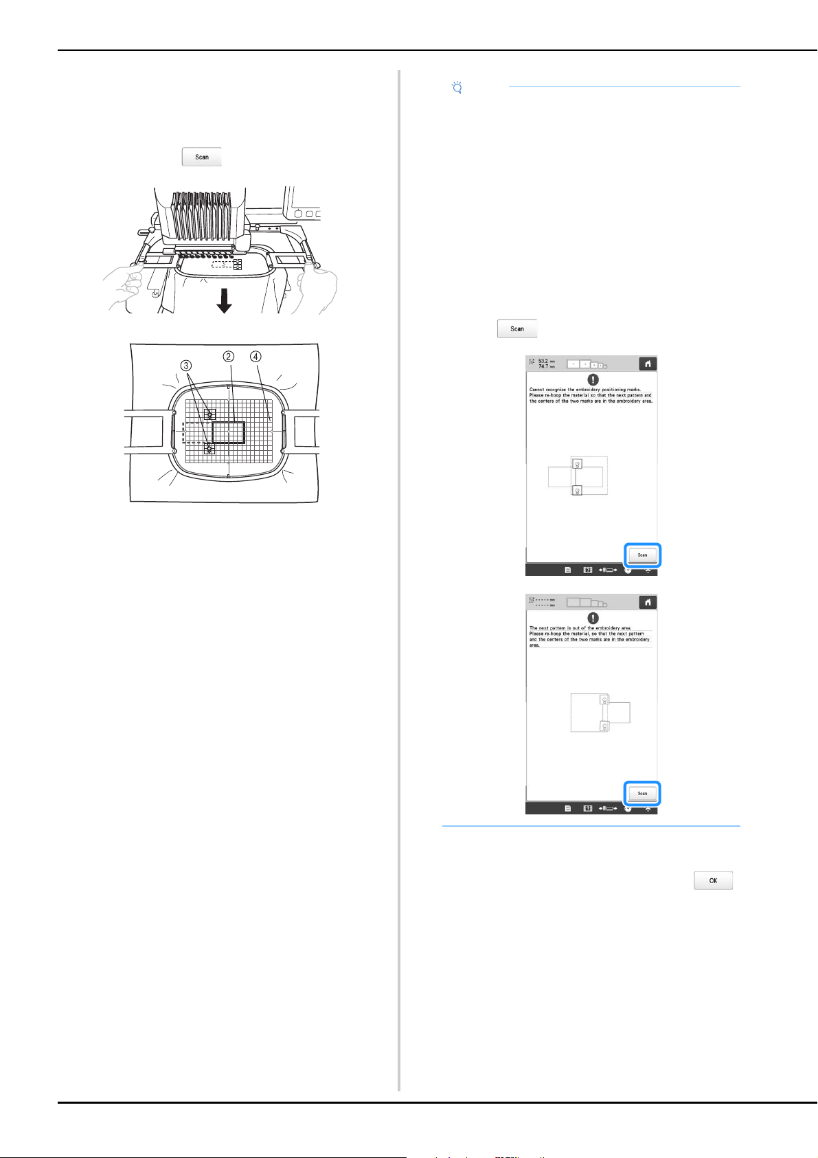
112
While making sure that the two positioning stickers do
not peel off, remove the embroidery frame from the
machine, and then rehoop the fabric. Be sure to hoop
the fabric so the next pattern and both the positioning
stickers are within the embroidering area. Reattach the
frame and touch .
2 Pattern to be embroidered next
3 Centers of large circles for stickers
4 Embroidery sheet
The camera detects the two positioning stickers.
o
After the positioning stickers have been detected, the
message to inform you that it recognized the
embroidery positioning sticker appears. Touch ,
and then remove the stickers.
Note
• If the next pattern and the centers of the large
circles of the two positioning stickers do not fit
within the embroidering area, use a larger
embroidery frame. If a larger embroidery frame
cannot be used, continue to step o, and then
refer to “Changing the position of a sticker” on
page 114 to reposition the sticker.
• If the sticker peels off during this procedure, the
patterns cannot be connected. If this occurs,
restart the procedure from the beginning.
• If either of the following messages appear, rehoop
the fabric so that the next pattern and both the
positioning stickers are within the embroidering
area as indicated in the screen.
Touch to detect the positioning stickers.
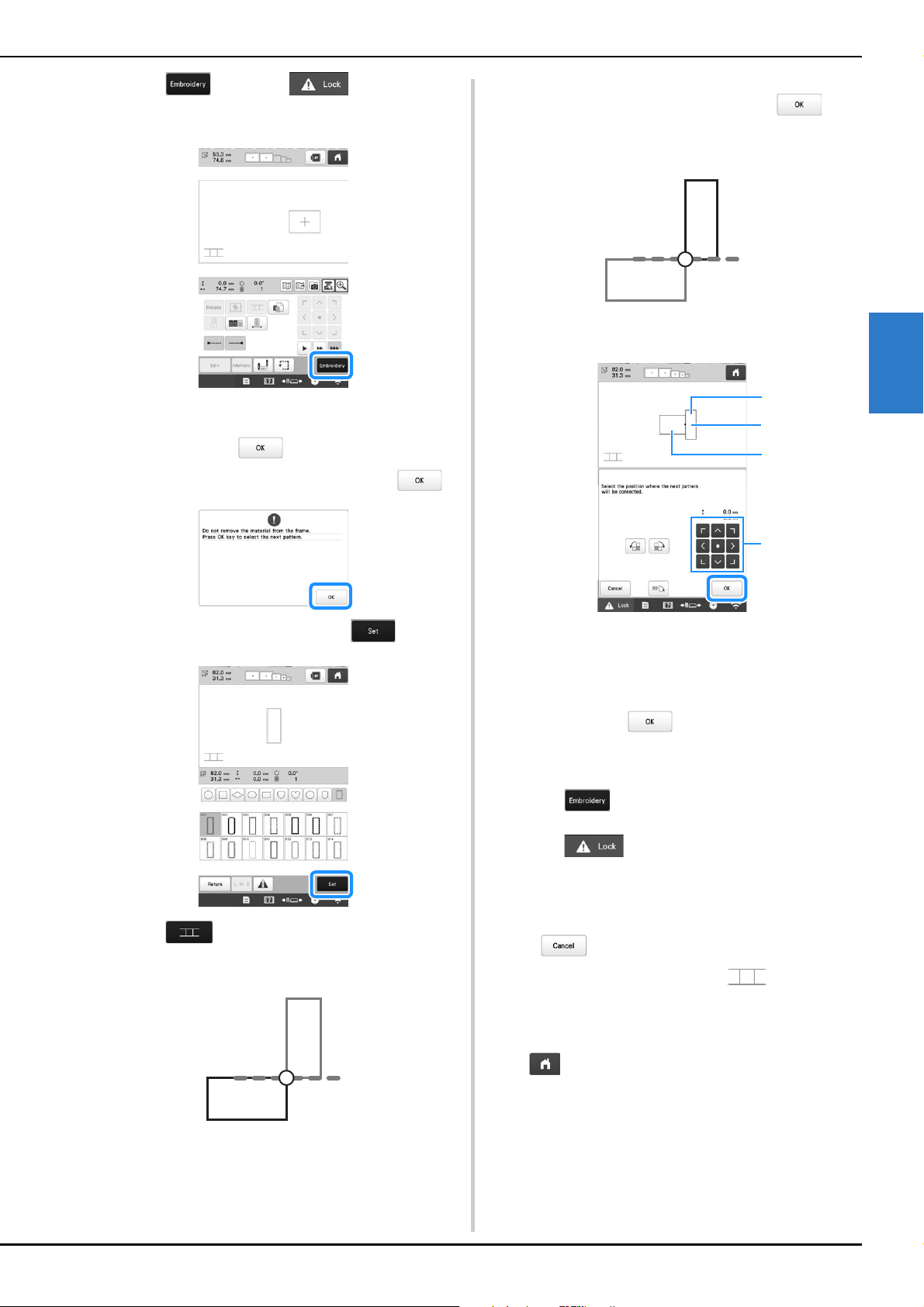
ADVANCED EMBROIDERY
113
3
p
Touch , then touch and then press
the “Start/Stop” button to embroider the second
pattern.
After embroidering of the second pattern is finished,
the message to confirm to connect the next pattern
appears. Touch .
q
When the following message appears, touch .
r
Select the third pattern C, and touch .
s
Touch to display the pattern connection
setting screen. In this example, we will select the top
point of the right edge for the second pattern.
t
Touch the position where the third pattern will be
connected on the screen, and then touch . In
this example, touch the upper right side of the second
pattern.
• Pattern rotates automatically when corner position is
selected.
1 Touch the connecting area
2 Third pattern C
3 Second pattern B
4 Move the third pattern.
Message appears on screen and carriage will move
after touching .
u
Follow the on-screen instruction to perform steps k
to
o.
v
Touch .
w
Touch and then press the “Start/Stop”
button to embroider the third pattern.
After embroidering of the third pattern is finished, the
message to confirm to connect the next pattern
appears. When finished connecting patterns, touch
.
After embroidering is finished, at the top left
side of the screen disappears.
The three patterns have been connected.
Touch to clear the pattern.
2
1
3
4
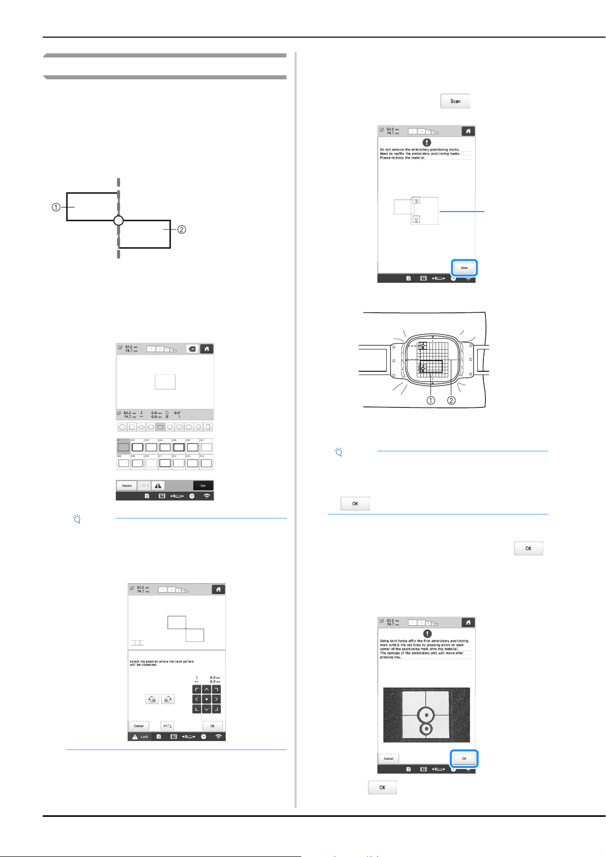
114
Changing the position of a sticker
If the selected pattern or positioning stickers for connecting
the next pattern do not easily fit in the embroidering area,
follow the on-screen instructions that appear after step m on
page 111 in order to move the positioning stickers.
For an example, the on-screen instruction appears when you
use the embroidery frame with a size of 10 cm × 10 cm (4
inches × 4 inches) to connect patterns as shown below.
a
Refer to steps a through m of“Connecting three
patterns” on page 109 using the embroidery frame
with a size of 100 mm × 100 mm (4 inches × 4 inches)
to embroider the first pattern and to connect the
second pattern.
b
Following message appears in step n if the next
pattern or affixed positioning stickers are close to
being out of the embroidering area. Follow the
instructions and then touch .
1 Embroidering area
1 Pattern to be embroidered next
2 Embroidery sheet
c
After the positioning stickers have been detected, the
message to inform you that it recognized the
embroidery positioning sticker appears. Touch ,
and then remove the stickers.
d
Affix the two positioning stickers again according to
the on-screen instructions so that the next pattern or
positioning marks can fit in the embroidery area.
Touch so that the camera detects the first
positioning sticker.
1 Pattern A
2 Pattern B
Note
• When referring to steps a through m of
“Connecting three patterns” on page 109, make
sure you select the pattern position to reflect this
exercise.
Note
• If the message that could not recognize the
embroidery positioning sticker appears, rehoop the
fabric as indicated in the screen, and then touch
.
1
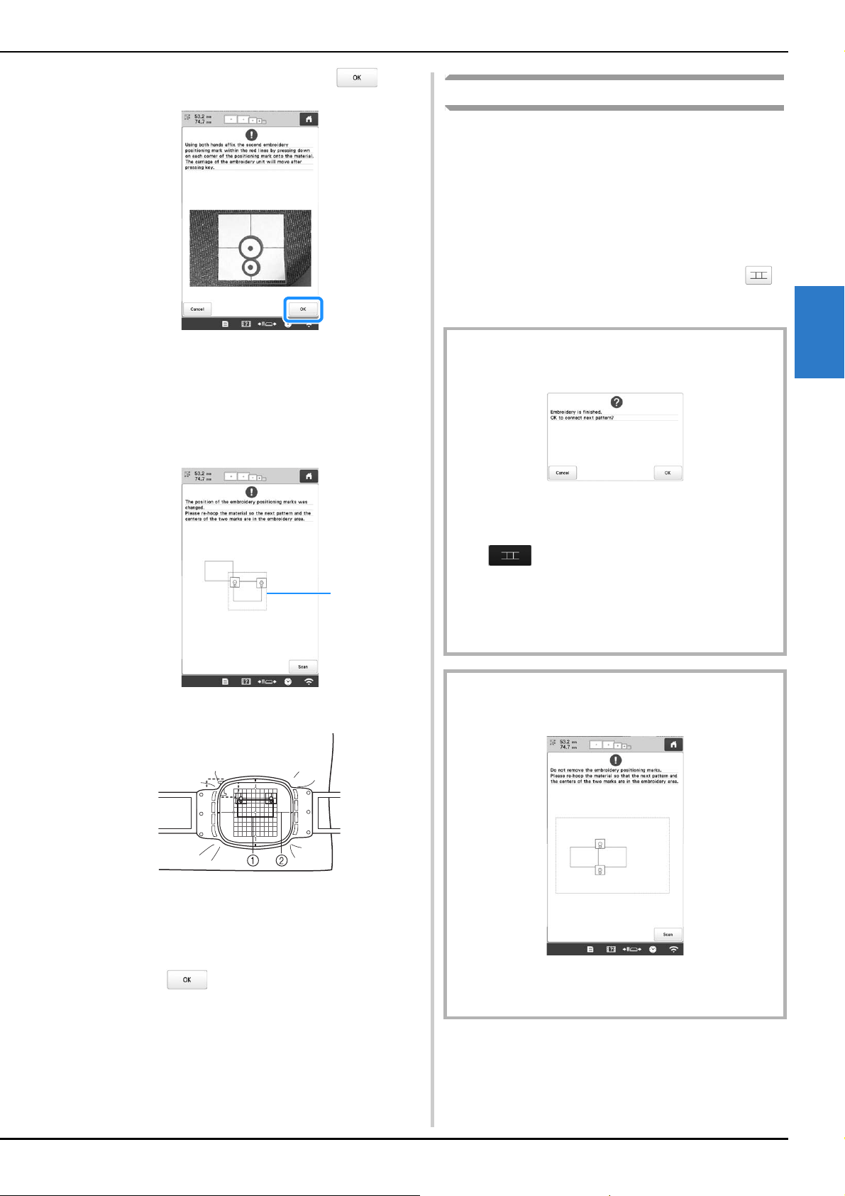
ADVANCED EMBROIDERY
115
3
e
Affix the second sticker and then touch .
The camera detects the second positioning sticker.
f
After the two positioning stickers have been detected,
the following message appears. While making sure that
the positioning stickers do not peel off, rehoop the
fabric according to the example displayed on the on-
screen instruction.
1 Embroidering area
1 Pattern to be embroidered next
2 Embroidery sheet
g
Continue the operation from step o on page 112 after
touching .
Resume feature
If the machine is turned off while the pattern connecting
function is being used, the machine will return to the
operation indicated below when it is turned on again. The
machine operation will differ depending on when it is turned
off.
Example: When connecting two patterns
1
Select the first pattern. Touch the pattern connection key .
Begin embroidering the first pattern.
Finish embroidering the first pattern. (A)
If the machine is turned off during any operation in this box, the
machine will return to (A) when it is turned on again.
Select the second pattern.
Touch .
Specify the reference point for connecting the pattern.
Start detecting positioning stickers (2 locations).
Finish detecting positioning stickers. (B)
If the machine is turned off during any operation in this box, the
machine will return to (B) when it is turned on again.
Rehoop the fabric.
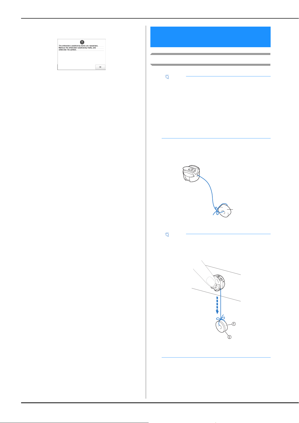
116
Adjusting the tension of the bobbin thread
a
Tie the included weight to the end of the thread
extending from the bobbin case.
Prewound bobbins
1 Weight (L)
Finish detecting positioning stickers (2 locations).
Begin embroidering the second pattern.
Finish embroidering the second pattern.
MAKING EMBROIDERY
ADJUSTMENTS
Note
• Be sure to check the tension of the bobbin thread
each time that the bobbin is changed.
Depending on the bobbin thread type and whether
a prewound bobbin is used, the tension of the
bobbin thread may differ. For example, when
replacing an empty prewound bobbin with one of
the same type, be sure to check the tension of the
bobbin thread and adjust the tension if necessary.
• Be sure to adjust the tension of the bobbin thread
before adjusting the tension of the upper thread.
Note
• Different weights are used to adjust prewound
bobbins and metal bobbins.
Metal bobbins:
1 Weight (L)
2 Weight (S) (included with the optional bobbin
winder)
a
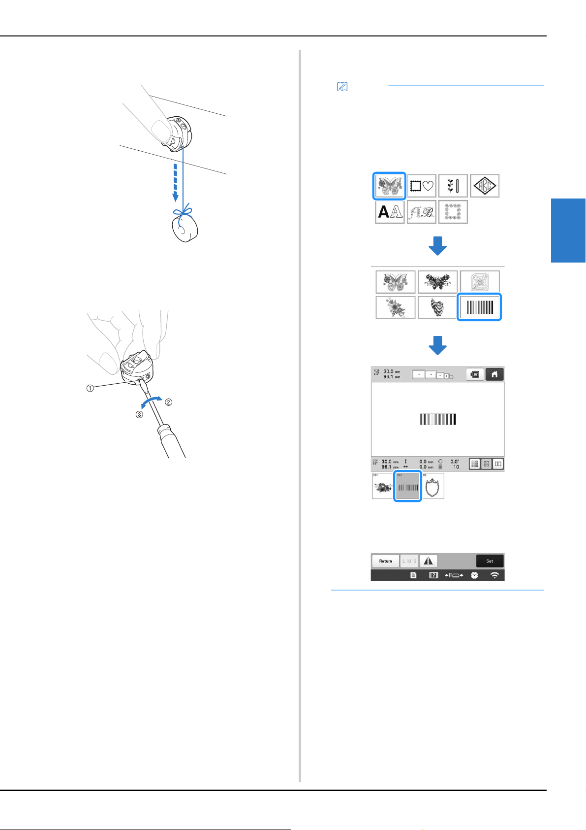
ADVANCED EMBROIDERY
117
3
b
As shown in the illustration, hold the bobbin case
against a smooth vertical surface.
• If the thread with the weight attached is slowly pulled
out, the thread tension is correct.
c
Use the included standard screwdriver to turn the
tension-adjusting screw and adjust the thread tension.
d
After making the adjustments, try embroidering with
all needle bars to check the thread tension.
1 Tension-adjusting
screw
2 Tighter
3 Looser
Memo
• In the built-in embroidery patterns, one pattern is
used for checking the thread tension. By
embroidering this pattern, the thread tension can
easily be checked. From the wrong side of the
fabric, the bobbin thread should be adjusted to be
about one third of the stitch width.
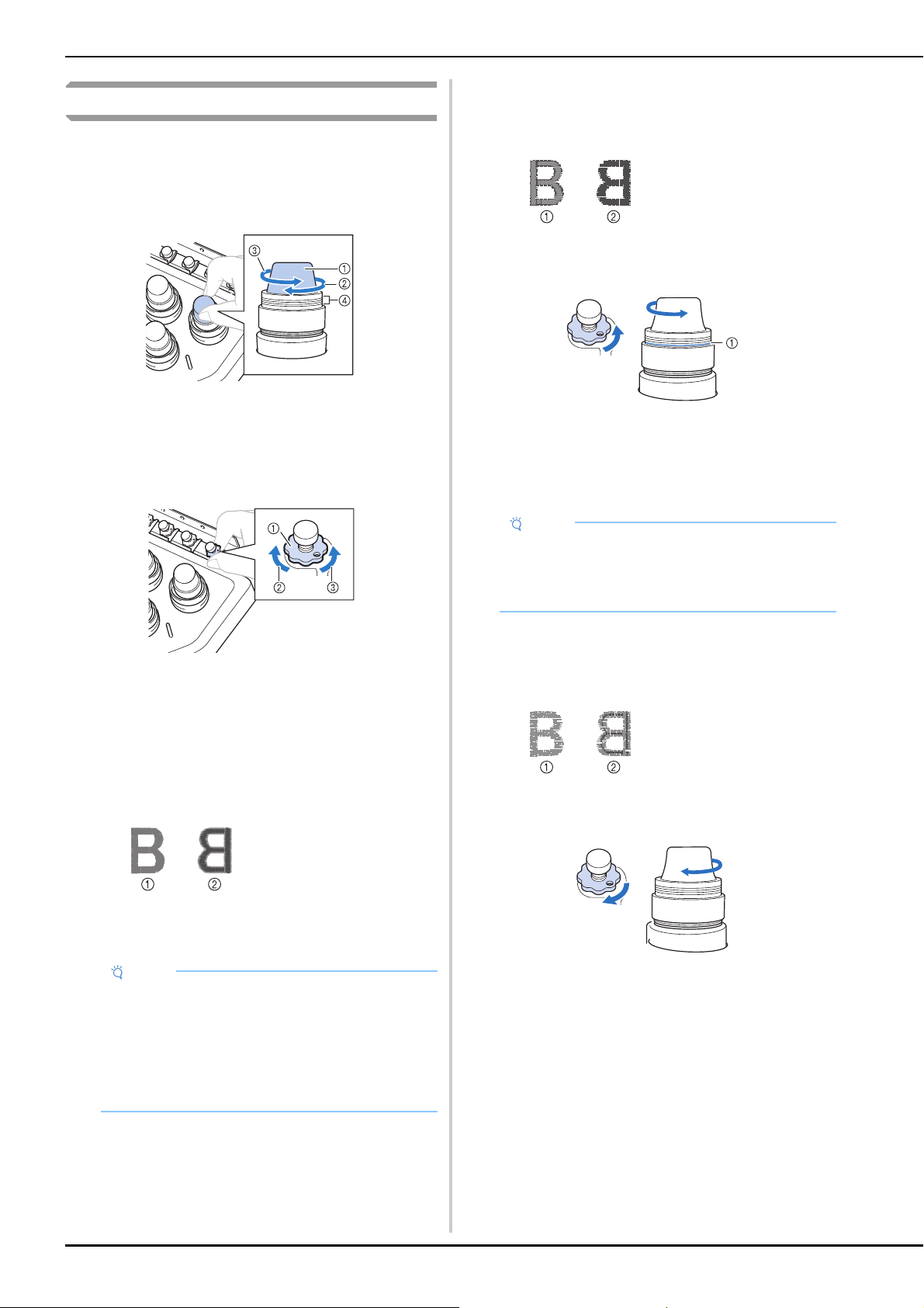
118
Adjusting the tension of the upper thread
When embroidering, the thread tension should be set so that
the upper thread can be seen slightly on the wrong side of the
fabric.
a
Turn the thread tension knobs.
1 Thread tension knobs
2 Tighter
3 Looser
4 Mark
If the thread tension is not still correctly adjusted,
turn the upper thread guide pretension knob.
1 Upper thread guide pretension knob
2 Tighter
3 Looser
■ Correct Thread Tension
The pattern can be seen from the wrong side of the fabric.
If the thread tension is not set correctly, the pattern will
not finish well. The fabric may pucker or the thread may
break.
Follow the operations described below to adjust thread
tension according to the situation.
■ Upper thread is too tight
The tension of the upper thread is too tight, resulting in the
bobbin thread being visible from the right side of the
fabric.
Turn the knob in the direction of the arrow to decrease the
tension of the upper thread.
1 Red line
If the red line is visible, the thread tension cannot be
decreased any further. Increase the tension of the bobbin
thread. (page 116)
■ Upper thread is too loose
The tension of the upper thread is too loose, resulting in a
loose upper thread, loose thread locks or loops appearing
on the right side of the fabric.
Turn the knob in the direction of the arrow to increase the
tension of the upper thread.
1 Right side
2 Wrong side
Note
• If you decrease the thread tension further than the
red line, the tension knob may be disassembled.
This is not a sign of a malfunction. Increase the
thread tension slightly, and begin embroidering
again.
• If necessary, refer to page 176 for reassembling the
tension unit.
1 Right side
2 Wrong side
Note
• If you decrease the thread tension further than the
red line, the tension knob may be disassembled.
• If necessary, refer to page 176 for reassembling the
tension unit.
1 Right side
2 Wrong side
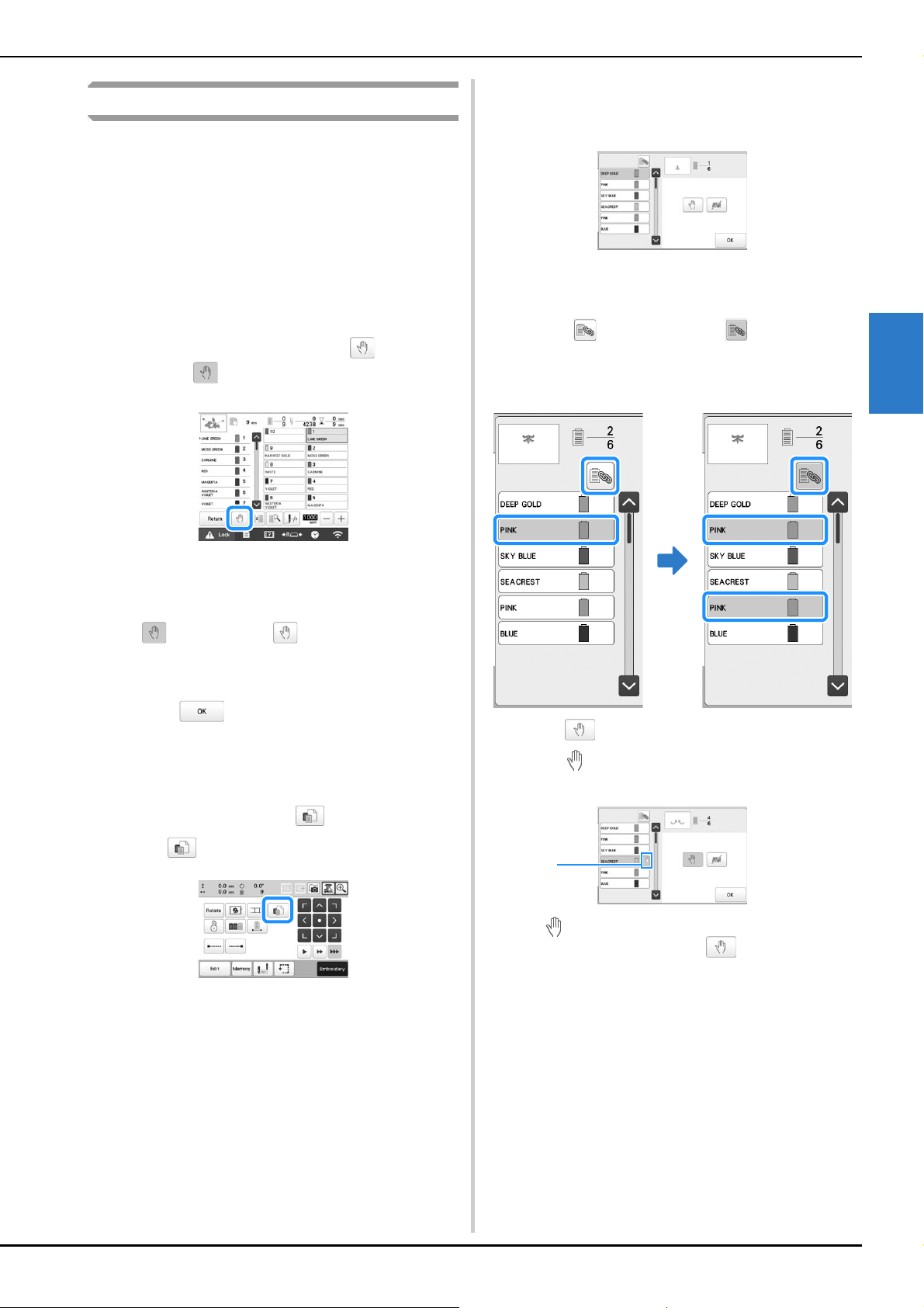
ADVANCED EMBROIDERY
119
3
Setting the machine to stop at color changes
The machine can be stopped at any time; however, if the
machine is stopped while it is embroidering, it is better to go
back a few stitches before continuing embroidering to overlap
the stitching. If the machine stops at a color change, it is not
necessary to go back through the stitching before continuing
embroidering.
■ Stopping the machine at the next color change
The machine can be set to stop before embroidering the
next color.
a
While embroidering the color before the point where
you wish to stop the machine, touch so that it
changes to .
b
After finishing embroidering the area for the current
color, the next needle bar moves into position and the
machine stops before embroidering the next color.
changes back to .
• If the machine is temporarily turned off, you will be
asked if you wish to continue embroidering or select a
new pattern when the machine is turned on again.
Touch to continue embroidering. (page 97)
■ Specifying pause locations before
embroidering
Pause locations can be specified in the pause setting
screen, displayed by touching .
a
Touch in the embroidering settings screen.
The pause setting screen appears.
b
From the thread color sequence display, select the
thread color where you wish to stop the machine
before continuing to embroider.
The selected thread color is highlighted in blue.
• If the same thread color is used more than once, they
can be combined. After selecting a thread color,
touch . The key changes to , and all thread
colors in the thread color sequence display that are
the same as the one that was selected are highlighted
in blue.
c
Touch .
The mark appears to indicate where the machine
will stop.
1 mark
• To cancel the setting, touch again.
d
Repeat steps b and c for each pause that you wish
to specify.
• Any number of pauses can be specified.
1
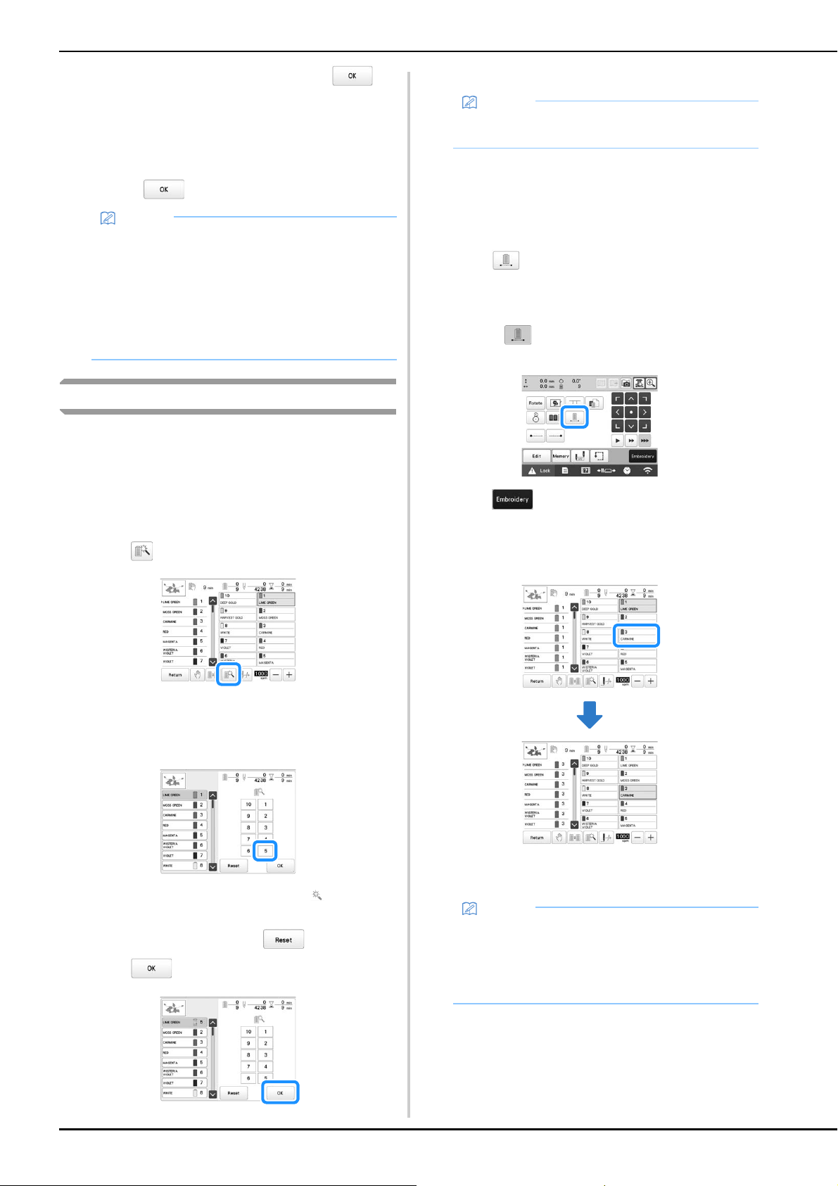
120
e
After specifying the desired settings, touch .
• If the machine is temporarily turned off when it is
stopped at the specified location after embroidering,
you will be asked if you wish to continue
embroidering or select a new pattern when the
machine is turned on again.
Touch to continue embroidering. (page 97)
Temporary needle bar setting
After embroidering begins, the machine can be stopped at a
color change and a different needle bar can be specified for
the next color to be embroidered.
By substituting an upper thread color already threaded on a
different needle bar, the time for embroidering can be saved.
For example, similar color thread can be substituted for
temporary use.
a
Touch .
The temporary needle bar setting screen appears.
b
Touch the key for the needle bar threaded with the
thread that you wish to embroider with.
The needle bar number changes and appears to
indicate the selected needle bar.
To cancel the setting, touch .
c
Touch .
The embroidering screen appears again.
■ Uninterrupted embroidering (one color)
A selected pattern can be stitched out in one color instead
of multi color. The machine will hesitate but not stop
between color steps, and then continue till the pattern is
completed.
a
Touch in the embroidering settings screen.
• The selected pattern will be embroidered in one
color, instead of changing the thread while
embroidering.
• Touch again to return to the pattern’s original
settings.
b
Touch to continue to the embroidering screen.
c
Touch the key for the needle bar threaded with the
thread you wish to embroider uninterruptedly.
The thread color sequence display and pattern for the
thread color of the selected needle bar appear.
Memo
• If the machine is temporarily turned off, the settings
to stop the machine at color changes specified
before the machine was turned off are not
cancelled. However, the settings are cancelled if a
new pattern is selected.
• If a pattern with the settings to stop the machine at
color changes is saved, the settings to stop the
machine at color changes are also saved.
Memo
• The thread color (needle bar) cannot be changed in
the middle of an area that is being embroidered.
Memo
• Even if uninterrupted embroidering has been set,
the DST thread trimming function can be used.
(page 123)
• After finishing the embroidery, uninterrupted
embroidery will be canceled.
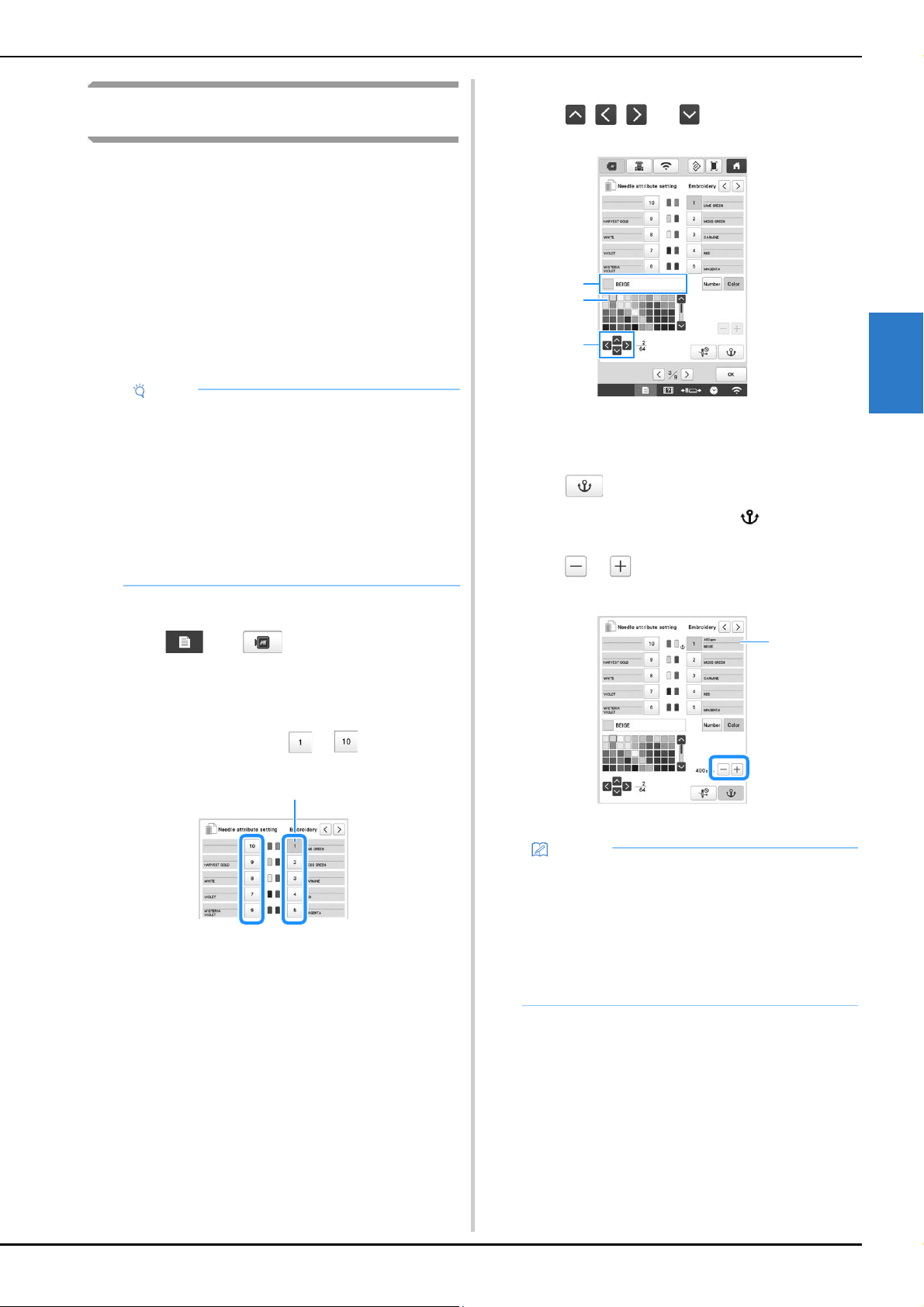
ADVANCED EMBROIDERY
121
3
Reserved needle bar and embroidery speed
settings
Normally, the machine automatically assigns thread colors to
the needle bars; however, a specific thread color can be
manually assigned to a certain needle bar. If a needle bar is
specified, that needle bar is removed from the machine’s
automatic assignments and the specified color remains
assigned to it.
By specifically assigning often used thread colors to certain
needle bars, the trouble of changing the thread spools can be
reduced.
Also, the maximum embroidery speed can be specified to the
assigned needle bar. It is useful when you specially set a weak
thread such as a metallic thread to the assigned needle bar.
Once a manual needle bar setting is specified, it remains
applied until the setting is cancelled.
a
Touch , then .
The embroidery settings screen appears.
b
Locate [Needle attribute setting].
c
Touch any of the key from to for the number
of the needle bar that you wish to specify.
1 The number of the selected needle bar turns blue.
d
Select the color to be assigned to the needle bar.
Touch , , and , or directly touch a color,
to select the desired color.
1 Displays the color that is selected and its name
2 The color in the box is the color that is selected.
3 The box moves in the direction of the arrow on the key
that is touched.
e
Touch .
The selected color of thread and appear on the
spool.
f
Touch or to set the maximum embroidery
speed for the assigned needle bar.
1 Value of maximum embroidery speed setting
Note
• This feature is not accessible through the
embroidering screen.
• You can assign thread colors up to 9 needle bars in
normal mode. When you set [Manual Color
Sequence] to [ON] in settings screen, it is available
to assign up to 10 needle bars. If you assign all the
10 needle bars in the [Manual Color Sequence]
mode, and then you set the machine to the normal
mode, the setting of needle bar 10 is canceled
automatically.
(page 58)
1
Memo
• Decrease the embroidery speed to 400 spm when
using a specialty thread, such as a metallic thread,
assigned to a needle bar. (“spm” is the number of
stitches embroidered in one minute.)
• The maximum embroidery speed specified here is
always effective to the assigned needle bar, even if
you set the faster speed in the embroidering
screen. (page 89)
1
3
2
1
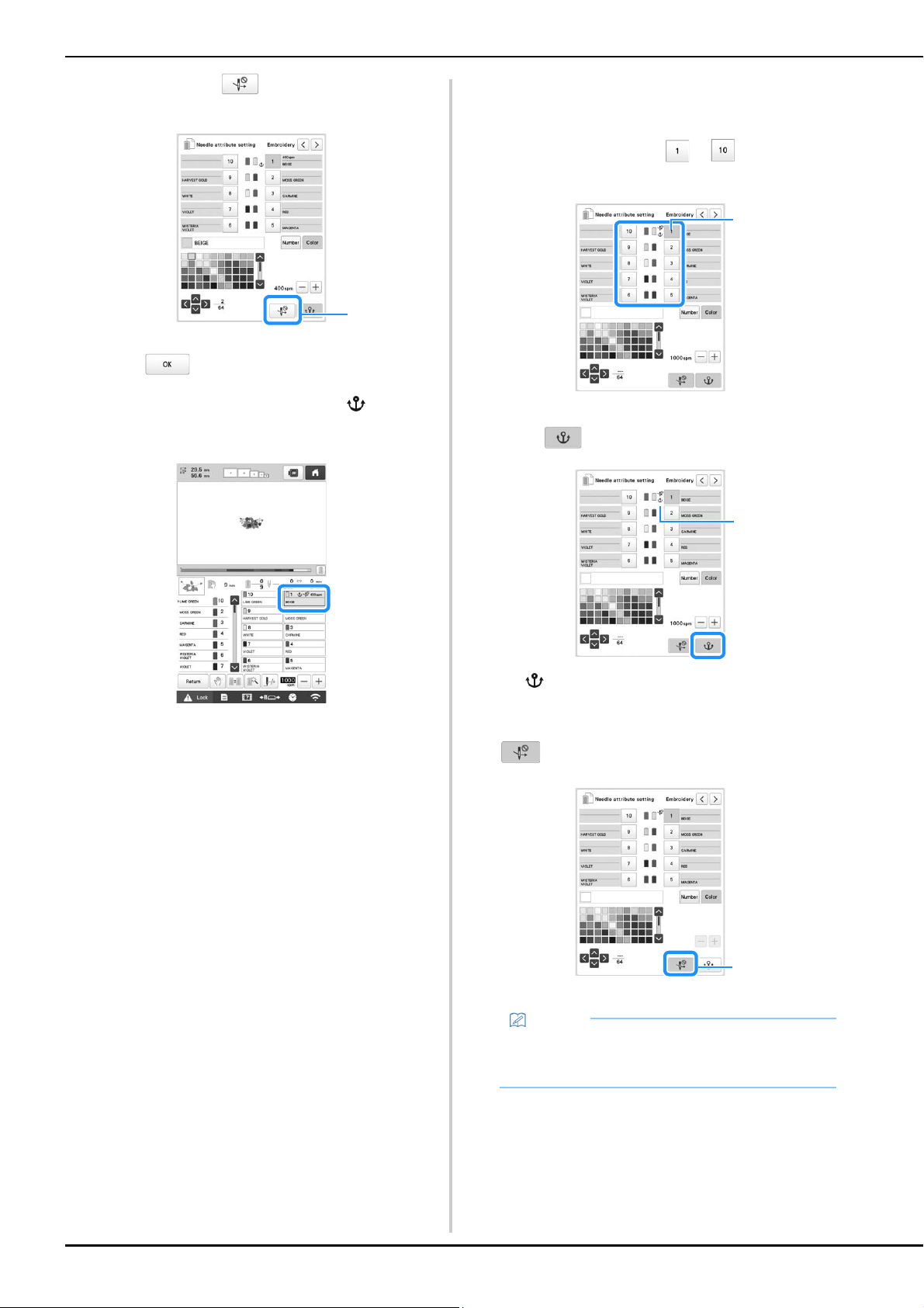
122
g
If necessary, touch to cancel automatic needle
threading.
1 Disable needle threader key
h
Touch .
• Specified needle bar is indicated with and the
specified maximum embroidery speed in the
embroidering screen.
■ Cancelling the setting
To change the setting, first cancel it, and then select the
new setting.
a
Touch any of the key from to for the number
of the needle bar whose setting you wish to cancel.
1 The number of the selected needle bar turns blue.
b
Touch .
1 disappears from the thread spool.
This cancels the manual needle bar setting.
c
To cancel the cancel needle threading setting, touch
again.
1 Disable needle threader key
1
Memo
• Follow the procedure from step d on page 121, to
assign the other thread color to the needle bar you
canceled the setting.
1
1
1
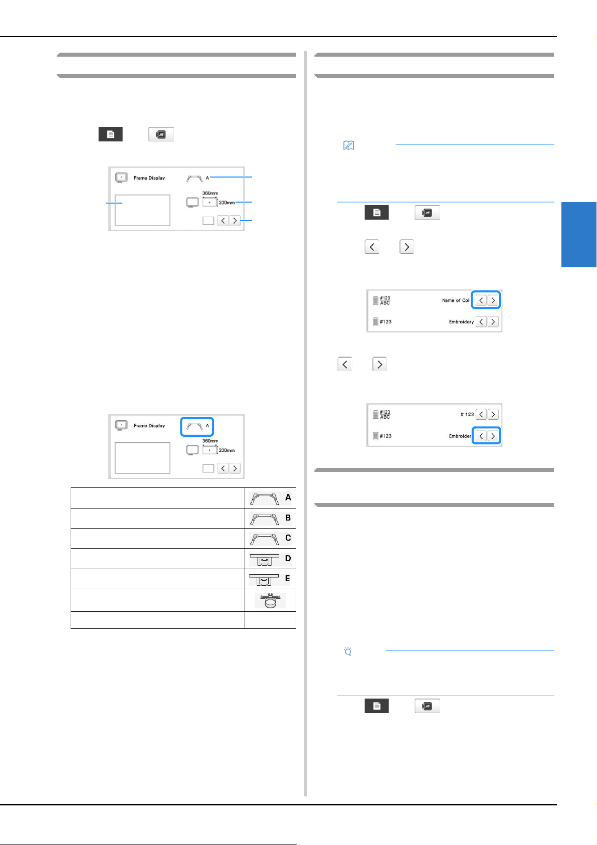
ADVANCED EMBROIDERY
123
3
Changing the display guides
The guides in the pattern display area can be specified. The
machine automatically detects the type of embroidery frame
holder and embroidery frame that are installed and displays
them.
Touch , then .
The embroidery settings screen appears.
1 How the guides will appear with the specified settings
can be previewed here.
2 Type of embroidery frame holder
Displays the type of the embroidery frame holder.
3 Area
Displays the size of the embroidery frame that is actually
installed. (page 66)
4 Center point marker or grid lines
Select the type of the center point marker and the grid
lines, and whether or not to display them.
■ Type of embroidery frame holder
The machine automatically detects the type of embroidery
frame holder that is installed.
If no embroidery frame holder is installed, the setting for
“Cap frame/Cylinder frame” is displayed.
* No icon appears since this frame is installed without
an embroidery frame holder.
Changing the thread color information
You can display the name of the thread colors, embroidery
thread number or the embroidering time.
When the machine is purchased, the thread color number
[#123] is selected.
a
Touch , then .
The embroidery settings screen appears.
b
Touch and to display the name of the thread
colors, the embroidery thread number or the
embroidering time.
c
When the thread number [#123] is displayed, touch
and to select from the embroidery thread
brand.
Specifying jump stitch trimming / “DST”
jump codes for trimming
You can specify whether or not jump stitches are cut. In
addition, when using Tajima embroidery data (.dst), you can
specify whether or not the thread is cut according to the
specified number of jump codes.
[ON]: The machine converts the “jump” code to a trim code,
based on the number specified on the next line.
[OFF]: The machine does not convert the “jump” code to a
trim code.
When the machine is purchased, [ON] is selected and the
number of jumps is set to [3].
a
Touch , then .
The embroidery settings screen appears.
Embroidery frame holder A (included)
Embroidery frame holder B (included)
Embroidery frame holder C (Optional)
Embroidery frame holder D (Optional)
Embroidery frame holder E (Optional)
Cap frame/Cylinder frame (Optional)
Magnetic sash frame (Optional)
*
1
4
3
2
Memo
• Colors on the screen may vary slightly from actual
spool colors.
• [Original], imported data retains the brand thread
created with the software, is set as a default.
Note
• If the setting is changed from the previous setting,
the new setting is applied to the subsequent
embroidery.
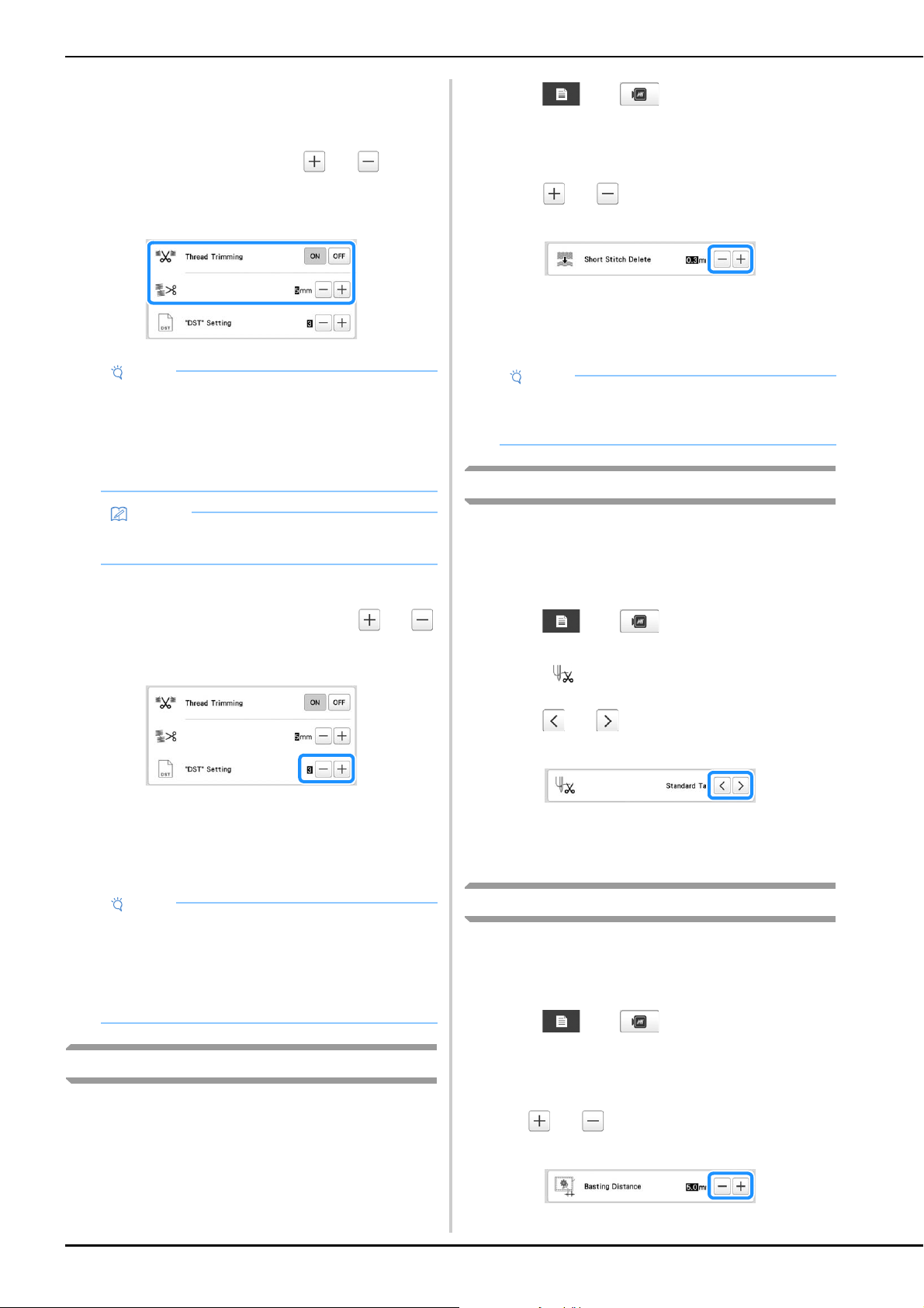
124
b
Locate [Thread Trimming].
c
Touch [ON] or [OFF] to select the desired setting.
When [ON] is selected, touch and to
specify the jump stitch length. For example, when
the value is set to [5 mm], jump stitches will be cut at
5 mm (13/64 inch), but not at 4 mm (5/32 inch).
■ When using Tajima embroidery data (.dst)
d
If [Thread Trimming] is set to [ON], touch and
to select the number of feed codes.
The desired setting is displayed.
• A value between [1] and [8] can be specified. For
example, if [3] is specified, sequential 3 jump codes
will be converted to the trim code. But sequential 2
jump codes will not be converted to the trim code, it
will be embroidered as the feed (jump) stitch.
Deleting short stitches
If embroidery data other than our original patterns are used,
the stitch length may be too short, possibly resulting in the
thread or the needle breaking. In order to prevent this
problem from occurring, the machine can be set to delete
stitches with a short stitch length. Stitches with a length less
than that specified in this function, can be deleted.
When the machine is purchased, [0.3] was selected.
a
Touch , then .
The embroidery settings screen appears.
b
Locate [Short Stitch Delete].
c
Touch and to select the stitch length.
The desired size is displayed.
• A value between 0 and 1 millimeters if the units of
measurements is set to [mm] (or a value between 0
and 0.04 inch if the units of measurements is set to
[inch]) can be specified.
Specifying the remaining length of thread
This setting specifies whether the length of upper thread that
remains threaded through the needle after the thread is
trimmed (length of thread passed through the eye of the
needle) has a standard tail or long tail.
When the machine is purchased, [Standard Tail] is selected.
a
Touch , then .
The embroidery settings screen appears.
b
Display .
c
Touch and to select the setting.
The desired length is displayed.
• If the machine misses stitches with a standard length
of thread after it is trimmed, select [Long Tail].
• When using metallic thread, select [Long Tail].
Changing the embroidery basting distance
The distance from the pattern to the basting stitching can be
set to 0.0 mm (0 inch) to 12.0 mm (1/2 inch).
When the machine is purchased, [5.0 mm] is selected. Refer
to page 99 when using this setting.
a
Touch , then .
The embroidery settings screen appears.
b
Locate [Basting Distance].
c
Use and to specify the distance from the
pattern to the basting stitching.
Note
• Even if [Thread Trimming] is set to [ON], this setting
is not applied to the jump stitch trimming of
threads between character patterns. For details on
jump stitch trimming for character patterns, refer to
“Trimming the threads between characters” on
page 47.
Memo
• The length of jump stitch trimming cannot be
specified to Tajima embroidery data (.dst).
Note
• You need to set the jump number same as the
number that was used when the particular Tajima
data was created.
If the jump number is not matched, either
unexpected trim or no trimming at trim expected
point will happen.
Note
• If the setting is changed from the previous setting,
the new setting is applied to the subsequent
embroidery.
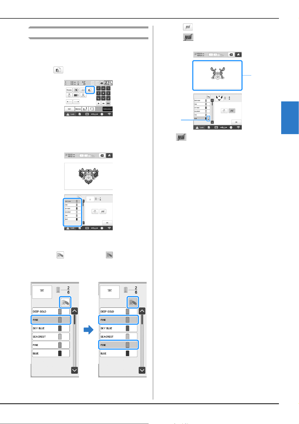
ADVANCED EMBROIDERY
125
3
Deselect region setting
The deselect region setting (which specifies that a thread color
will not to be embroidered) can be applied to a part of the
pattern with a specific color. In this way, you can arrange the
embroidery without actually editing the pattern.
a
Touch in the embroidering settings screen.
A screen appears, allowing the needle bar numbers
to be selected.
b
From the thread color sequence display, select the
thread color that will not be embroidered.
The selected thread color is highlighted in blue.
• If the same thread color is used more than once, they
can be combined. After selecting a thread color,
touch . The key changes to , and all thread
colors in the thread color sequence display that are
the same as the one that was selected are highlighted
in blue.
c
Touch .
The mark appears to indicate that the selected
thread color will not be embroidered.
1 mark
2 The parts of the pattern that will not be embroidered are
hidden.
d
Repeat steps b and c for all thread colors that will
not be embroidered.
1
2
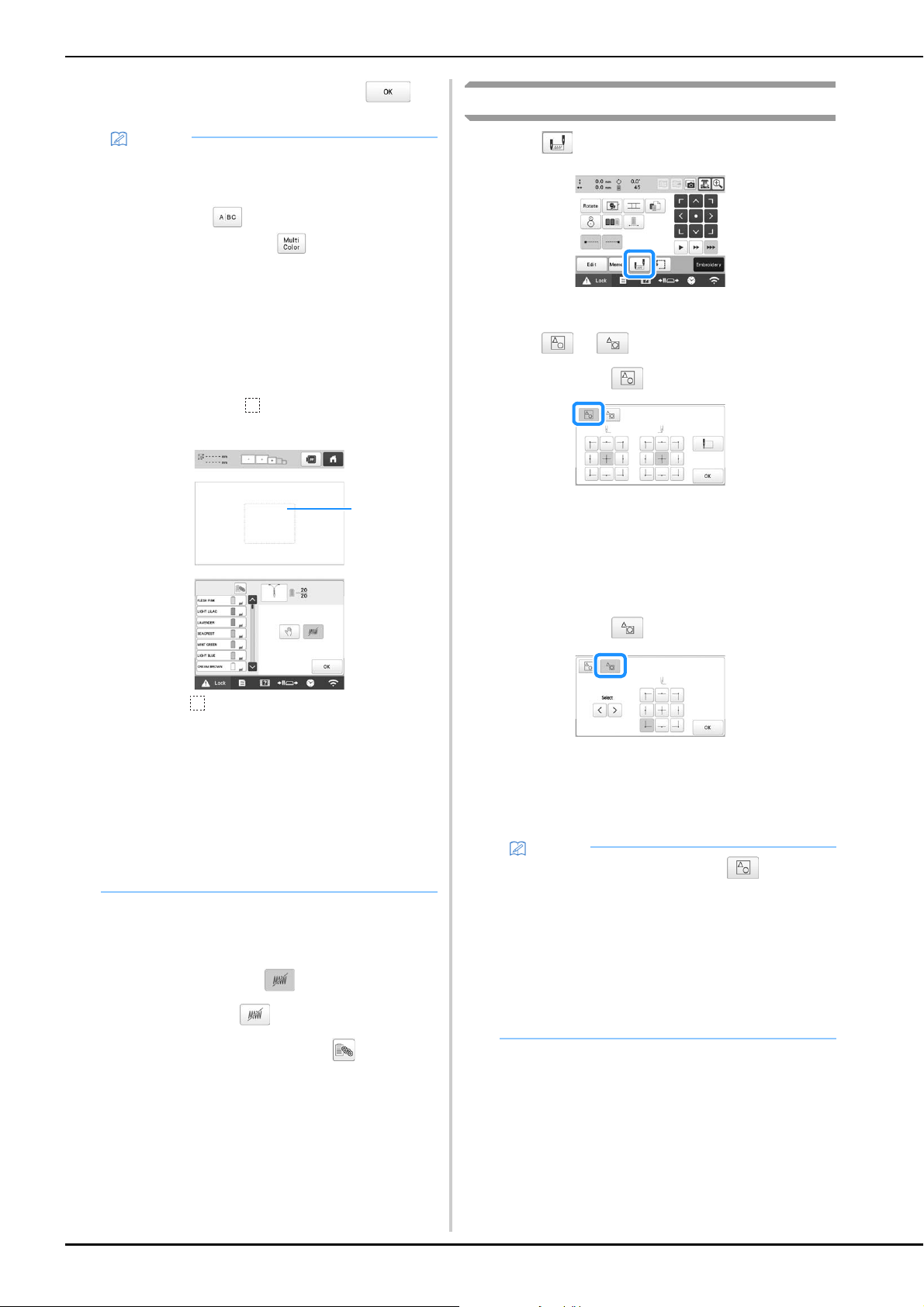
126
e
After specifying the desired settings, touch .
■ Cancelling the deselect region setting
a
Select the thread color whose setting is to be
cancelled, and then touch .
The key changes to , and the deselect region
setting is cancelled.
• If thread colors were combined with , the deselect
region setting will also be cancelled for all thread
colors that are the same as the one that was selected.
Starting/ending position settings
a
Touch in the embroidering settings screen.
The starting/ending position settings screen appears.
b
Select or .
• When selecting
The machine can set the starting point and the ending
point separately from the 9 points of the pattern. Those
are upper-left corner, upper-center, upper-right corner,
center-left, center, center-right, lower-left corner, lower-
center and lower-right corner.
This function can be used to repeatedly embroider a
pattern along a diagonal. (page 127)
• When selecting
When rotating the pattern while checking the
embroidering position shown by the camera, the
embroidering starting position can be set using a mask
based on the pattern before it has been rotated, which is
useful for aligning. (page 75)
Memo
• If the deselect region setting is applied to a
character pattern, all characters in the pattern will
not be embroidered. To deselect region for a single
character, use to separate the character
pattern (page 44), or use (page 54).
If the Multi Color key is used to specify that thread
colors not be embroidered, multi-color text cannot
be turned off.
• The parts with the deselect region setting applied
are not deleted. They can be reverted to being
embroidered (refer to “Cancelling the deselect
region setting” on page 126).
• If the deselect region setting has been applied to all
thread colors, a red appears at the location of
the pattern.
1 Red
• If the machine is temporarily turned off, the settings
to deselect region that were specified before the
machine was turned off are not cancelled.
However, the settings are cancelled if the same
pattern is selected again.
• When a pattern with the deselect region setting
applied is saved, the deselect region setting is also
saved. However, the pattern cannot be saved if the
deselect region setting is applied to all thread
colors.
1
Memo
• When the machine is purchased, is selected
and both the starting position and the ending
position are set to the center of the pattern.
• The starting/ending position settings do not
change until the key for a new setting is touched.
The settings specified before the machine is turned
off remain selected the next time that the machine
is turned on. (If an embroidery positioning sticker is
used to align the pattern, or basting is added or
removed, the setting will return to its default.)
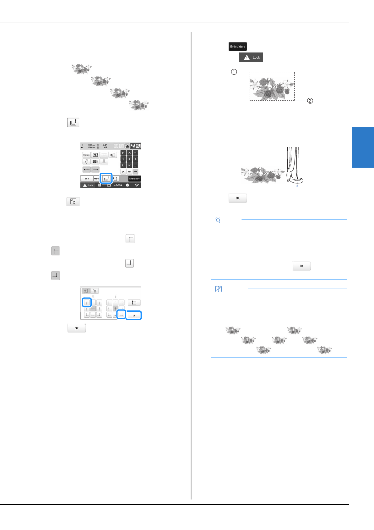
ADVANCED EMBROIDERY
127
3
■ Repeatedly embroidering a pattern along a
diagonal
Example
a
Touch in the embroidering settings screen to
display the starting/ending position settings screen.
b
Select .
c
Specify the upper-left corner as the starting position
and the lower-right corner as the ending position.
For the starting position, touch so that it changes to
.
For the ending position, touch so that it changes to
.
Touch to close the starting/ending position
settings screen.
d
Embroider the first pattern.
Touch to display the embroidering screen, and
then touch and press the “Start/Stop” button.
1 Starting position
2 Ending position
e
After embroidering is finished, the machine stops at the
lower-right corner of the pattern.
f
Touch and repeat steps d and e three
times.
Note
• If the next embroidery pattern of the series will be
stitched outside the embroidery field, the message
to inform you that it cannot set the starting/ending
position will appear.
Rehoop the fabric to continue to repeat the
embroidering pattern. Touch and repeat
steps
d and e.
Memo
• If the starting position and ending position settings
are changed, instead of embroidering the patterns
in a fixed direction, various pattern designs are
possible.
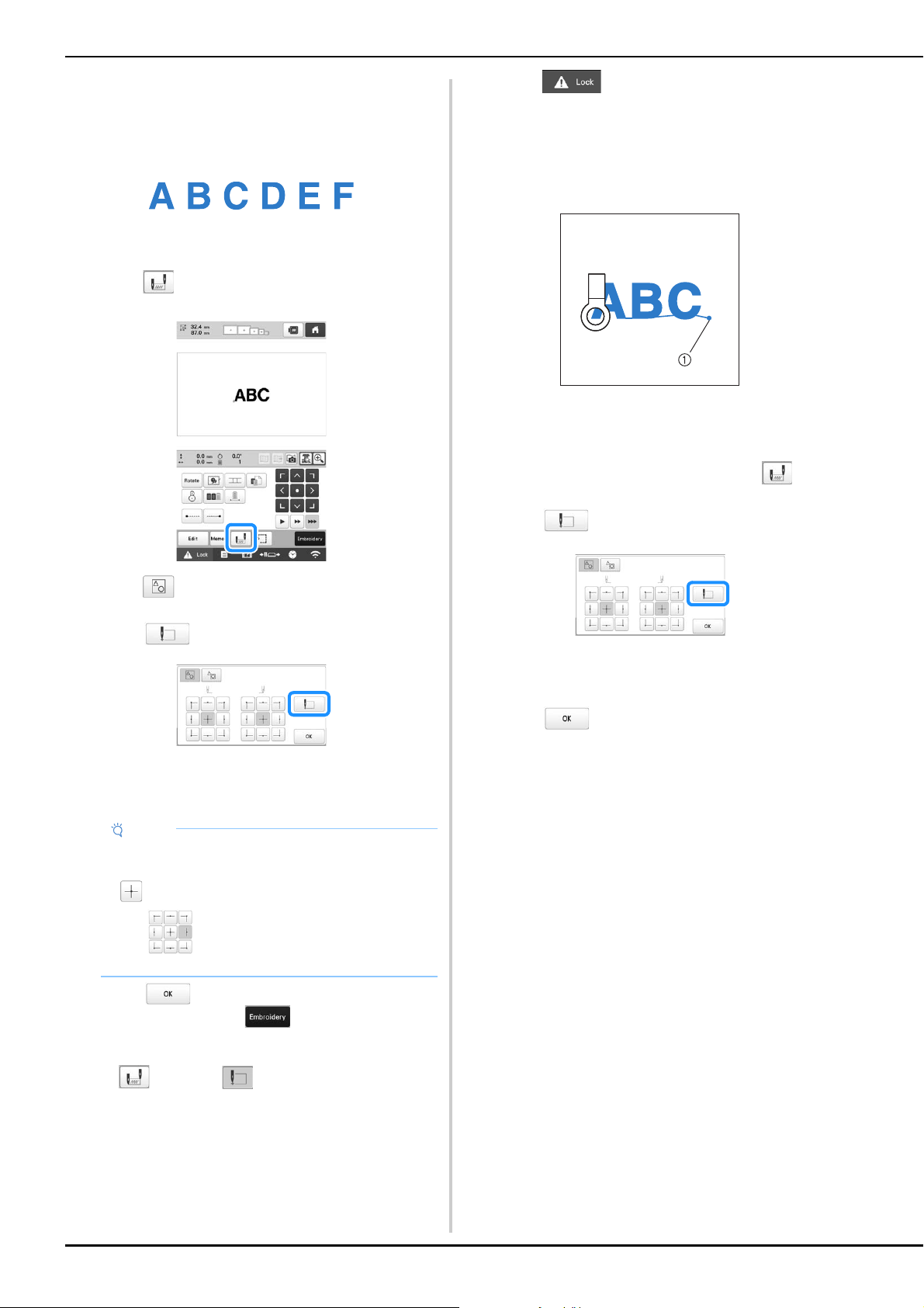
128
■ Embroidering aligned characters
Follow the procedure described below to embroider
aligned characters in a single row when the pattern
extends beyond the embroidery frame.
Example: Aligning “DEF” to the characters “ABC”
a
Select the character patterns for “ABC”.
b
Touch in the embroidering settings screen.
c
Select .
d
Touch .
The needle bar is positioned in the lower-left corner
of the pattern. The embroidery frame moves so that
the needle is positioned correctly.
e
Touch to return to the embroidering settings
screen, and then touch
to continue to the
embroidering screen.
changes to while the starting point is set
in the lower-left corner of the pattern.
f
Touch , and then press the “Start/Stop”
button to begin embroidering.
g
After the characters are embroidered, cut the threads,
remove the embroidery frame, and then attach the
embroidery frame again so that the remaining
characters (“DEF”) can be embroidered.
1 End of the embroidering
h
As in step a, select the character patterns for “DEF”.
i
In the embroidering settings screen, touch .
j
Touch .
The needle bar is positioned in the lower-left corner
of the pattern. The embroidery frame moves so that
the needle is positioned correctly.
k
Touch .
Note
• To cancel the starting point setting and return the
starting point to the center of the pattern, touch
.
• Use to select a different starting point for
embroidering.

ADVANCED EMBROIDERY
129
3
l
Use to align the needle with the end of
embroidering for the previous pattern.
• Touch to check the needle drop point on the
LCD screen. Before displaying the camera image,
specify the appropriate image settings. (page 73)
- Better camera image results can be achieved with
the appropriate settings.
• Touch to zoom up the camera view.
m
Touch .
n
Touch , and then press the “Start/Stop”
button to begin embroidering the remaining character
patterns.
■ Embroidering a pattern aligned with a mark on
the fabric
By specifying the beginning of stitching and the end of
stitching, the exact position of the pattern can be checked.
a
Touch in the embroidering settings screen.
b
Select .
c
Set the beginning of stitching in the lower-left corner.
The frame moves so that the needle drop point aligns
with the beginning of stitching.
d
With a fabric marker, mark this point on the fabric.
e
Set the beginning of stitching in the lower-right corner.
The frame moves so that the needle drop point aligns
with the beginning of stitching.
f
With a fabric marker, mark this point on the fabric.
g
Remove the embroidery frame from the machine, and
then connect these two points to check the
embroidering position.
• If the baseline is misaligned or intersects another line,
reframe the fabric in the embroidery frame or adjust
the position of the pattern.
Note
• You can also follow the procedure of “Finding the
embroidering position” on page 80, by directly
place the needle over the end of the previous
pattern.
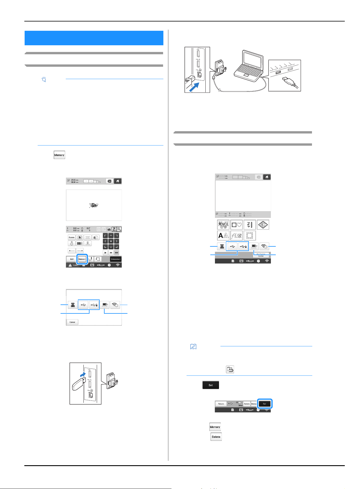
130
Saving embroidery patterns
a
Touch when the pattern you want to save is in
the embroidering settings screen.
b
Touch the desired destination to start saving.
1 Save to the machine’s memory.
2 Save to the USB media. The pattern is saved in a folder
labeled [bPocket].
When saving the embroidery pattern in a USB media,
insert the USB media into the USB port on the machine.
3 Save to the computer.
When saving the embroidery pattern to a computer,
connect a computer and the machine by using the
included USB cable. Plug the included USB cable into
the USB ports on the machine.
• Select the pattern’s .phx file in “Removable Disk” and
copy the file to the computer.
4 Save the pattern to the computer via the wireless
network connection. For detailed procedures, refer to
PE-DESIGN manual (version 11 or later).
Retrieving embroidery patterns
a
Touch the desired destination, and then select the
desired embroidery pattern.
1 Retrieve from the machine’s memory.
2 Retrieve from a USB media.
When retrieving the patterns from a USB media, insert
the USB media into the USB port on the machine.
3 Retrieve from a computer.
When retrieving the patterns from a computer, use the
included USB cable to connect the computer and the
machine. Plug the USB cable connector into the
corresponding USB ports for the computer and for the
machine.
4 Retrieve the pattern via the wireless network connection.
For detailed procedures, refer to PE-DESIGN manual
(version 11 or later).
b
Touch .
* To save embroidery patterns to another memory,
touch , and then select the desired destination.
* Touch to delete the embroidery pattern.
USING THE MEMORY FUNCTION
Note
• Do not turn the main power to OFF while the
[Saving…] screen is displayed. You will lose the
pattern you are saving.
• Embroidery patterns cannot be transferred via
wireless transmission if the computer and machine
are connected to different home networks. Be sure
to connect to the same home network.
• For details on supported computers, refer to
“SPECIFICATIONS” on page 190.
1
4
3
2
Memo
• If the embroidery pattern to be retrieved is in a
folder of the USB media, touch the key for that
folder. Touch to return to the previous screen.
1
4
3
2
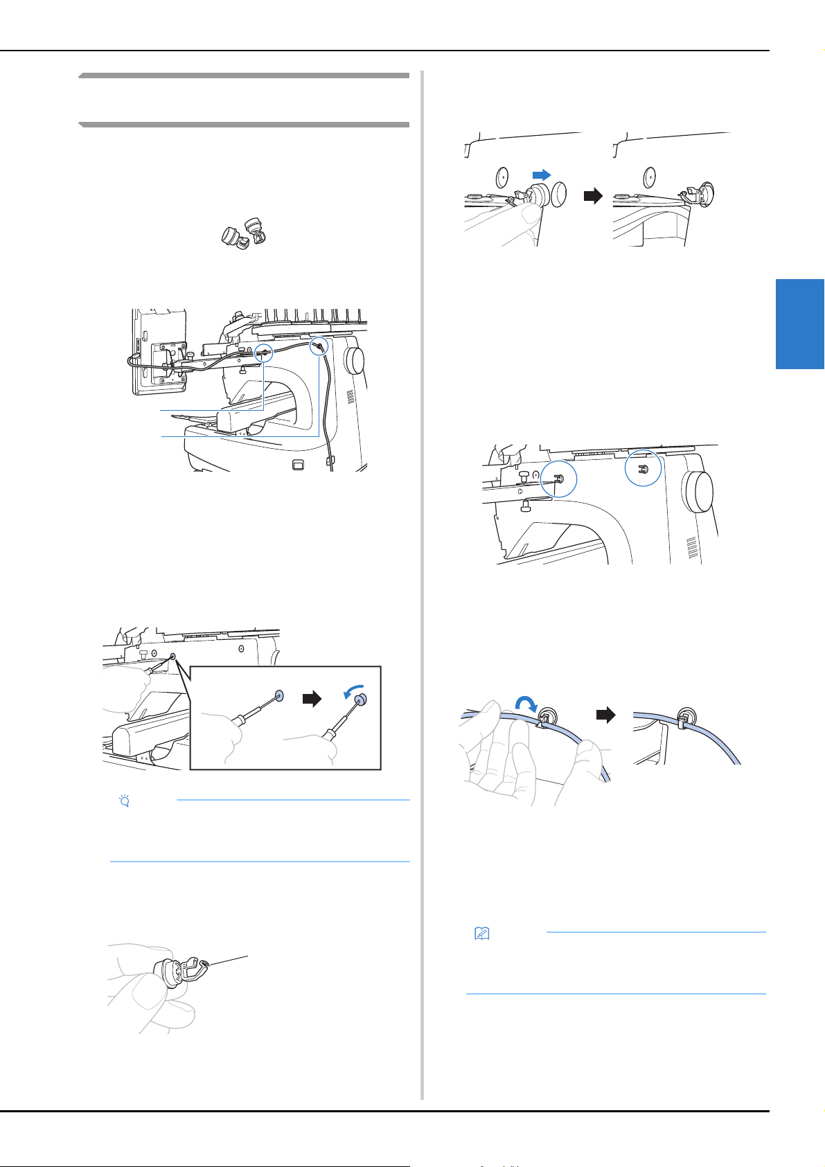
ADVANCED EMBROIDERY
131
3
Connecting the USB using the included USB
cord clamps
When connecting the machine to a computer, use the
included USB cord clamps to keep the cord away from the
carriage.
Included cord clamps
Installation positions of the USB cord clamps
1 Front screw hole on the side of the machine
2 Rear screw hole on the side of the machine
a
Using the included Allen screwdriver, remove the
protective cap covering the front screw on the side of
the machine.
• Insert the end of the Allen screwdriver into the hole in
the protective cap, and then lightly pull out the
protective cap to remove it.
b
Open the USB cord clamp.
• With your fingernail, press on the tab to open the
clamp.
c
Hold the clip end of the USB cord clamp, and then
firmly insert the other end into the screw hole where
the protective cap was removed.
d
As described in steps a through c, remove the
protective cap from the rear screw hole on the side of
the machine, and then insert an opened USB cord
clamp.
e
Check that the USB cord clamps have been firmly
inserted into the front and rear screw holes on the side
of the machine.
• If the USB cord clamps are not firmly inserted into the
screw holes, they are not correctly installed. Firmly
insert the cord clamps into the screw holes.
f
Pass the USB cable through the front USB cord clamp,
and then close the clamp to secure the cable.
• When passing the USB cable through the clamp, do
not insert it with excessive force; otherwise, the clamp
may break.
g
Using the same operation described in step e, secure
the USB cable with the rear USB cord clamp.
h
Arrange the USB cable between the USB cord clamps
so that the cable does not interfere with the operation
of the machine.
Note
• Do not insert the Allen screwdriver too far into the
hole in the protective cap; otherwise, the machine
or the Allen screwdriver may be damaged.
1 Tab
a
b
a
Memo
• Store the protective caps, which were removed in
step
a, in the included accessory case so they
will not be lost.
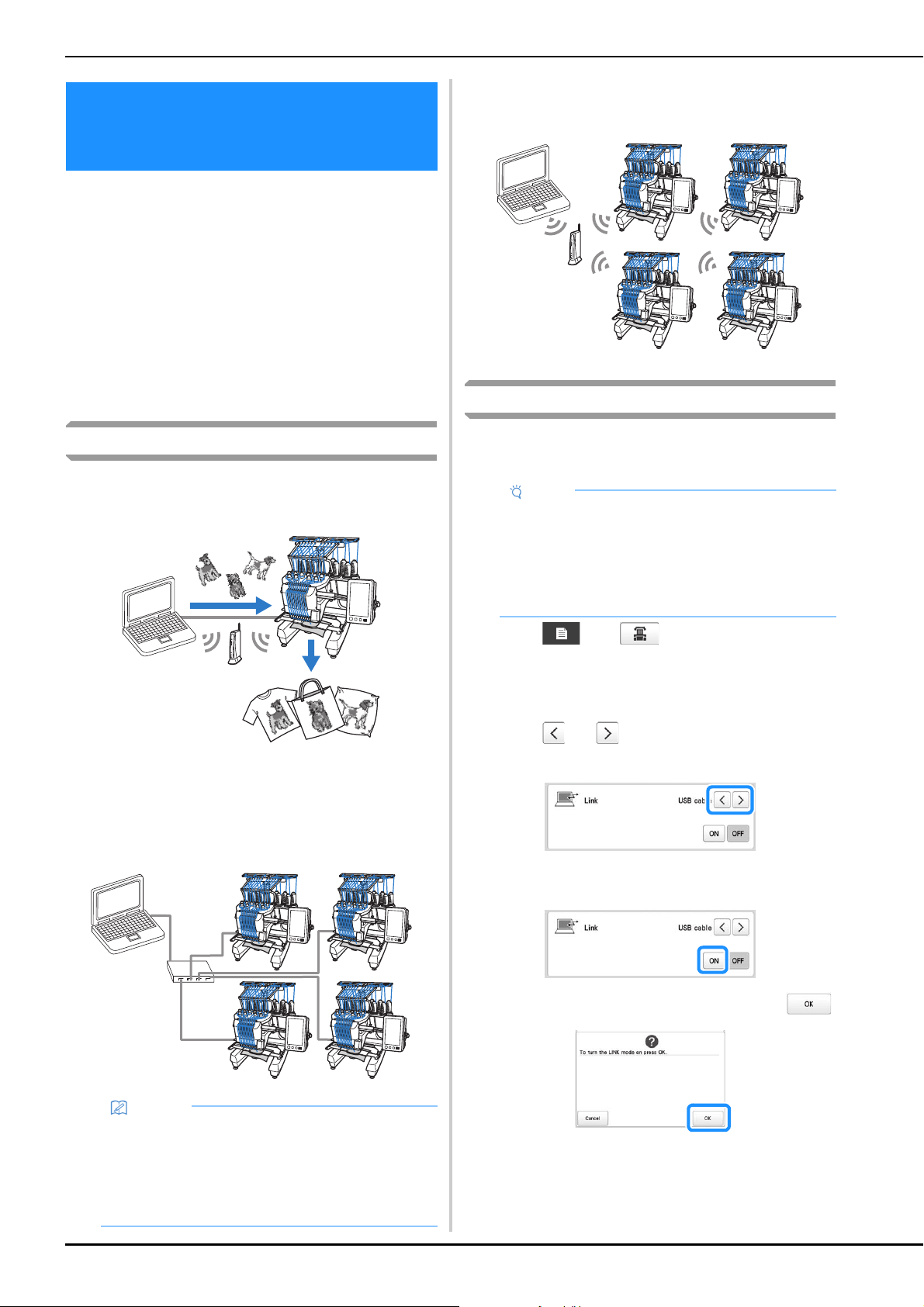
132
This machine is compatible with the Link function. This
function allows embroidery patterns edited in embroidery
software with the Link function, such as PE-DESIGN NEXT
or later, to be transferred from a computer to multiple
machines. As many as 100 embroidery patterns can be
transferred to a machine, and the embroidering status of
the patterns being transferred can be viewed from the
computer monitor.
Use the included USB cable or the wireless LAN function
to connect the machine to a computer. To transfer patterns
via the wireless network connection, use PE-DESIGN
version 11.2 or later.
Operations available with the Link function
■ Send multiple embroidery patterns to
connected machines
■ Check the embroidering status of the machine
(this model) from the computer
(Example of multiple machines connected by the USB
cable)
• A maximum of four machines can be connected.
(Example of multiple machines connected by the wireless
LAN function)
• A maximum of ten machines can be connected.
Embroidering using the Link function
First, use the embroidery editing software to create the
embroidery pattern to be sent to the machine.
a
Touch , then .
The general settings screen appears.
b
Locate [Link].
c
Touch and to select [USB cable] or [Wireless
LAN].
d
Touch [ON] to enable the Link function.
When the following message appears, touch .
SENDING EMBROIDERY PATTERNS
FROM A COMPUTER TO THE
MACHINE (LINK FUNCTION)
Memo
• When connecting multiple machines to the
computer, use a commercially available USB hub.
Please note that we recommend you use a self-
powered USB hub. Do not use USB extension
cables or repeater cables. For details on using the
USB hub, refer to its operating instructions.
Note
• Embroidery data in the PES format (.pes) can be
embroidered using the Link function.
• The Link function cannot be used with split (large-
size) patterns. (page 135)
• Attach to the machine the embroidery frame for the
size of the pattern to be sent.
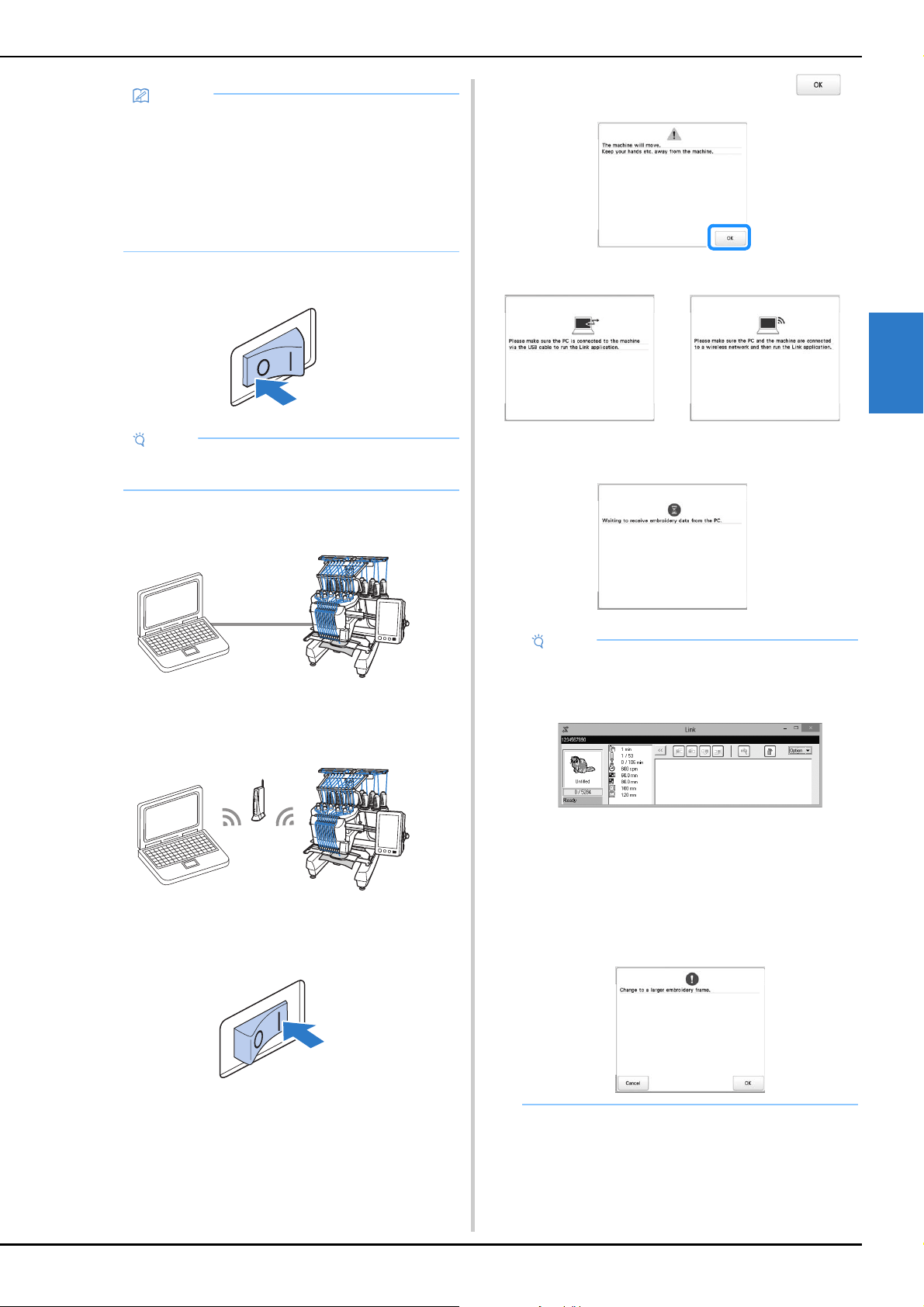
ADVANCED EMBROIDERY
133
3
e
Turn off the machine.
f
Connect the machine to the computer.
• USB cable connection
When connecting the machine to the computer, use the
included USB cord clamps. (page 131)
• Wireless LAN connection
For details on the wireless LAN connection, refer to
page 29.
g
Turn on the machine.
h
Using embroidery editing software with the Link
function, such as PE-DESIGN NEXT or later from a
computer, send the pattern to the machine in the Link
mode.
i
When the following message appears, touch .
A message appears in the machine’s LCD while the
machine is connecting to computer.
Memo
• When the Link function by the USB cable
connection is turned on while [Wireless LAN
Enable] is set to [ON], the message to set [Wireless
LAN Enable] to [OFF] appears.
• When the Link function by the wireless LAN
connection is turned on while [Wireless LAN
Enable] is set to [OFF], the message to set
[Wireless LAN Enable] to [ON] appears.
Note
• When you turn off the machine, wait for about 5
seconds before turning on the machine again.
• USB cable connection • Wireless LAN connection
Note
• For details on using the embroidery editing
software, refer to the Instruction Manual included
with it.
* This Link dialog box is found in PE-DESIGN
NEXT software.
• If the following error message appears, the type of
embroidery frame installed on the machine is not
compatible with the size of the pattern. Replace the
embroidery frame with one compatible with the
size of the pattern.
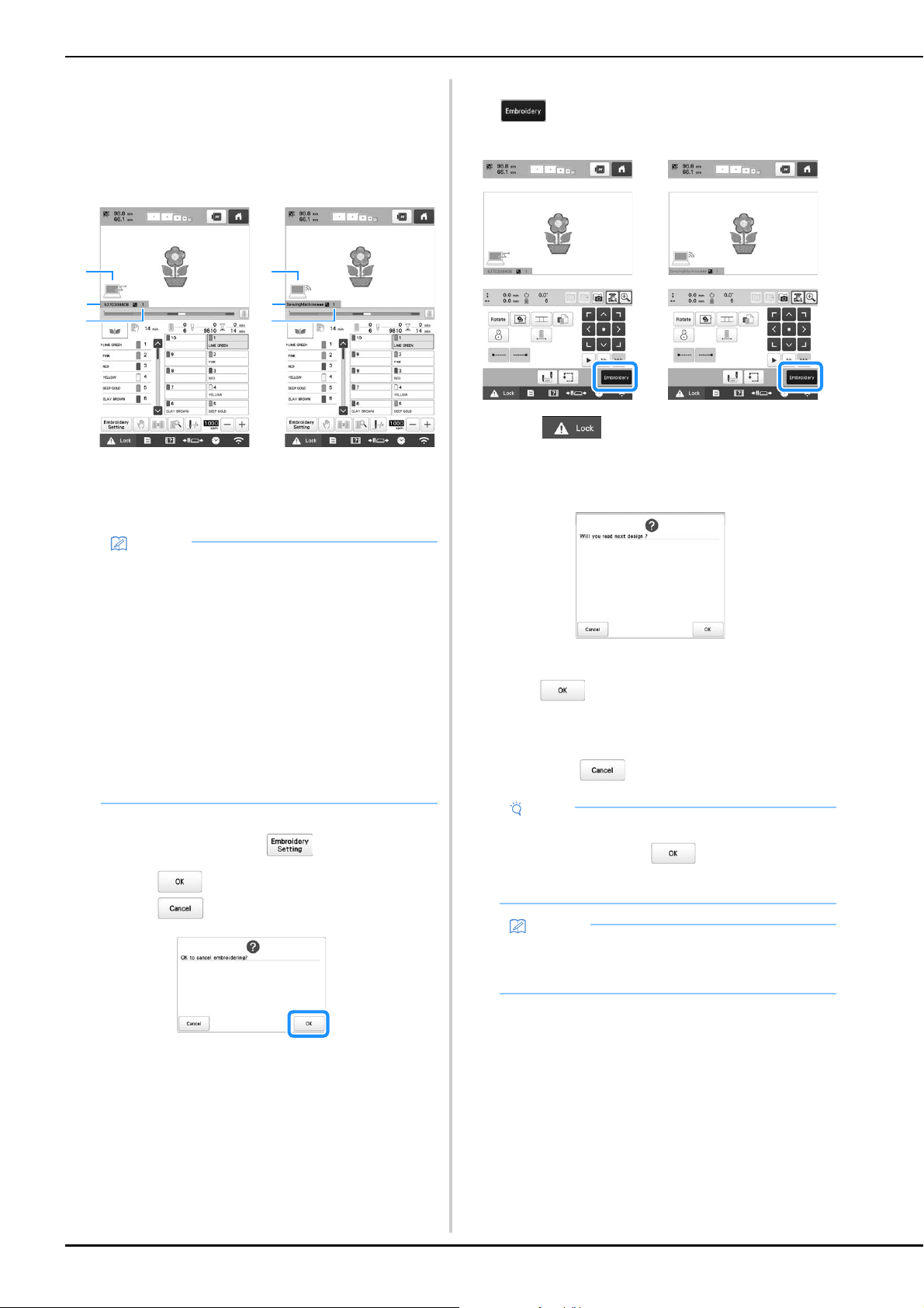
134
j
After the embroidery pattern has been opened by the
machine, the embroidering screen appears.
The opened embroidery pattern appears in the
pattern display area with the icon for the Link
function.
k
To change the embroidering settings for the opened
embroidery pattern, touch .
• Touch when the following message appears.
Touch to return to the embroidering screen.
The embroidering settings screen appears.
l
After the desired settings have been specified, touch
to return to the embroidering screen.
m
Touch , and then press the “Start/Stop”
button to start embroidering.
When embroidering is finished, the following
message appears.
n
To open another pattern sent from the computer,
touch , and then repeat the procedure starting
from step j to continue embroidering.
To stop embroidering or to embroider the same pattern
again, touch .
• USB cable connection • Wireless LAN connection
1 Icon for Link function
2 10-digit machine ID
3 Number of the pattern in
the queue
1 Icon for Link function
2 The machine’s name
3 Number of the pattern in
the queue
Memo
• While the machine is connected to the computer,
the machine’s status can be displayed by using a
function of the embroidery editing software. If
multiple machines are connected at the same time,
check the status of the machines using the 10-digit
machine ID that appears in the machine’s screen.
The following information can be viewed from the
computer.
- Machine’s status
- Information on the embroidery data being
embroidered and received by the machine (time
until the next time that the machine stops,
number of color changes, embroidering time,
maximum embroidery speed, pattern size, size of
frame being used on the machine)
2
1
3
2
1
3
• USB cable connection • Wireless LAN connection
Note
• The embroidering screen settings specified in step
l are saved even if was touched to
continue embroidering after embroidering is
finished.
Memo
• If the machine is turned off while it is embroidering,
the resume operation can be used the next time it
is turned on.
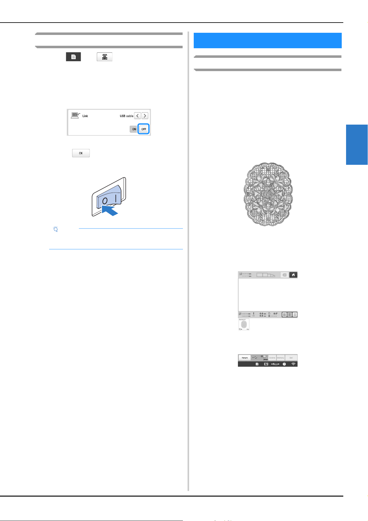
ADVANCED EMBROIDERY
135
3
Disabling the Link function
a
Touch , then .
The general settings screen appears.
b
Locate [Link].
c
Touch [OFF] to disable the Link function.
When the message to finish the Link mode appears,
touch .
d
Turn off the machine.
Embroidering split (large-size) patterns
Split (large-size) patterns created with PE-DESIGN version 7 or
later can be embroidered. With large-size patterns,
embroidery designs larger than the embroidery hoop are
divided into multiple sections, which combine to create a
single pattern after each section is embroidered.
For details on creating large-size embroidery patterns and for
more detailed embroidering instructions, refer to the manual
included with PE-DESIGN version 7 or later.
The following procedure describes how to read the large-size
embroidery pattern shown below from USB media and
embroider it.
a
Connect to the machine the media containing the
created large-size embroidery pattern, and then select
the large-size embroidery pattern to be embroidered.
* For details on retrieving patterns, refer to page 130.
A screen appears so that a section of the large-size
embroidery pattern can be selected.
Note
• When you turn off the machine, wait for about 5
seconds before turning on the machine again.
EMBROIDERY APPLICATIONS
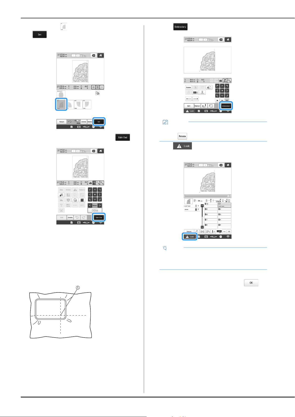
136
b
Select section to be embroidered, then touch
.
• Select the sections in alphabetical order.
c
If necessary, edit the pattern. Then, touch .
• For details, refer to “EDITING THE EMBROIDERY
PATTERN” on page 44.
d
Confirm the pattern size, and then select the
appropriate fabric and the embroidery frame.
• Be sure to select fabric of the size of combined
pattern.
e
Hoop the appropriate part of the fabric. In this case,
hoop upper-left part of the fabric.
f
Touch .
g
Touch , and then press the “Start/Stop”
button to embroider the pattern section.
h
When embroidering is finished, the message to confirm
to embroider the next part appears. Touch .
A screen appears so that a section of the large-size
embroidery pattern can be selected.
1 Center of fabric
Memo
• The pattern can be rotated to either the left or right
when is touched.
Note
• The last step of the stitching of the pattern section
will be an alignment stitching. Use this stitching for
placement of adjacent pattern section.
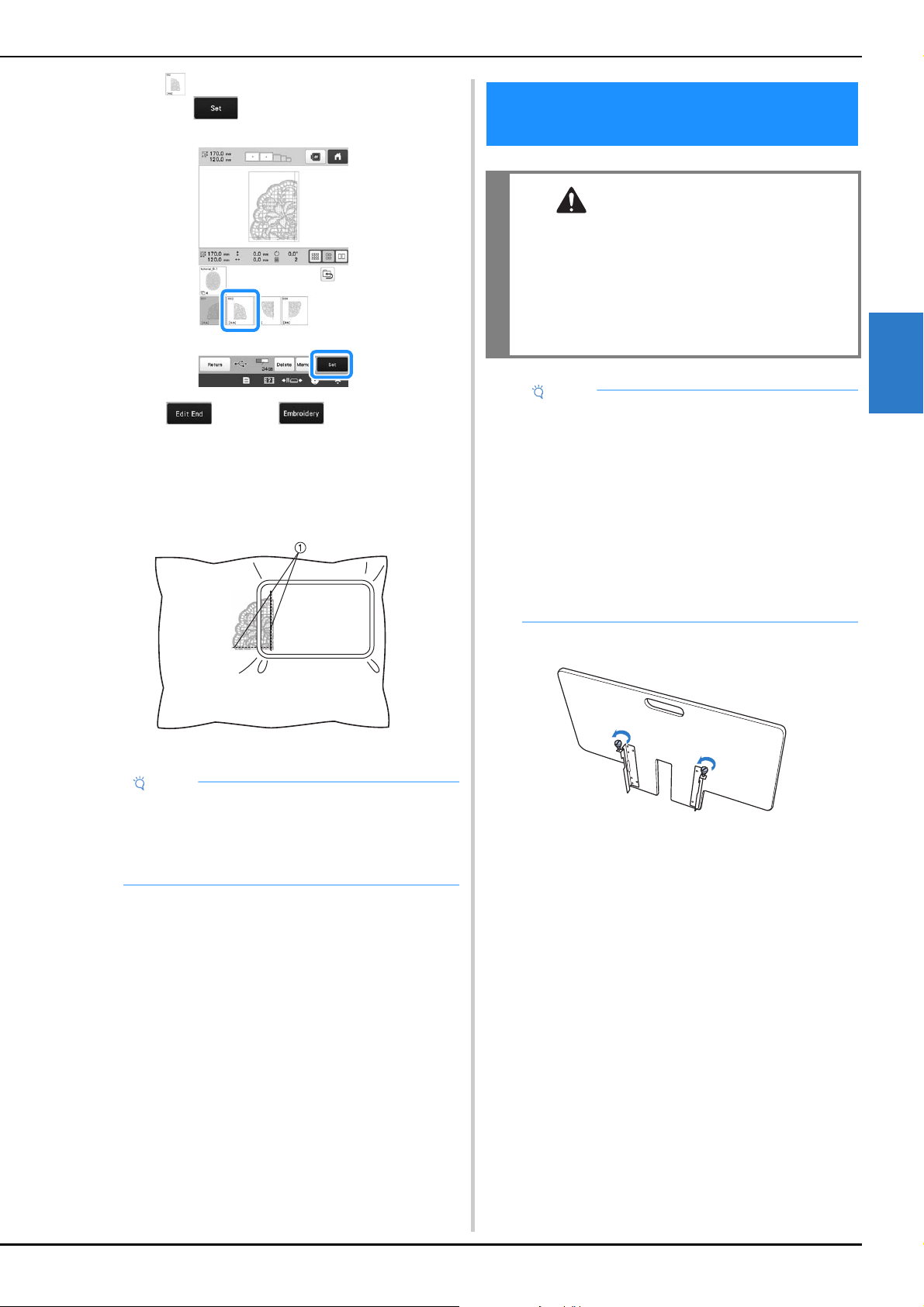
ADVANCED EMBROIDERY
137
3
i
Touch to select the next section of the pattern, and
then touch .
j
Touch , and then .
k
Hoop the fabric for the next design section aligning on
the alignment stitching. In this case, align the left side
of the hoop on the right side of the design section
embroidered in step
f.
1 Alignment stitching
l
Repeat steps g to j to embroider and combine the
remaining sections of the pattern.
a
Loosen the two thumb screws 5 to 6 turns.
Note
• Make sure that the alignment stitching is
completely within the embroidery field. Set the
embroidery sheet inside the embroidery frame and
align the grid with the alignment stitching for easier
placement.
INSTALLING THE INCLUDED WIDE
TABLE
CAUTION
• Be sure to install the wide table when using the
optional magnetic sash frame, jumbo frame,
border frame, quilt frame or flat frame. If these
frames are used without the wide table
installed, the weight of the frame and fabric
may cause the frame to slant and result in poor
embroidering quality.
Note
• When carrying the wide table, be sure to hold it
with both hands.
• Attach the wide table to the machine before
installing the embroidery frame.
• Do not place heavy objects on top of the installed
wide table or press down on it.
• Remove the wide table from the machine while
using embroidery frame that do no need to be used
with the wide table or while embroidering tubular
items, bags or caps. The embroidery frames for
these types of objects cannot be installed while the
wide table is attached to the machine.
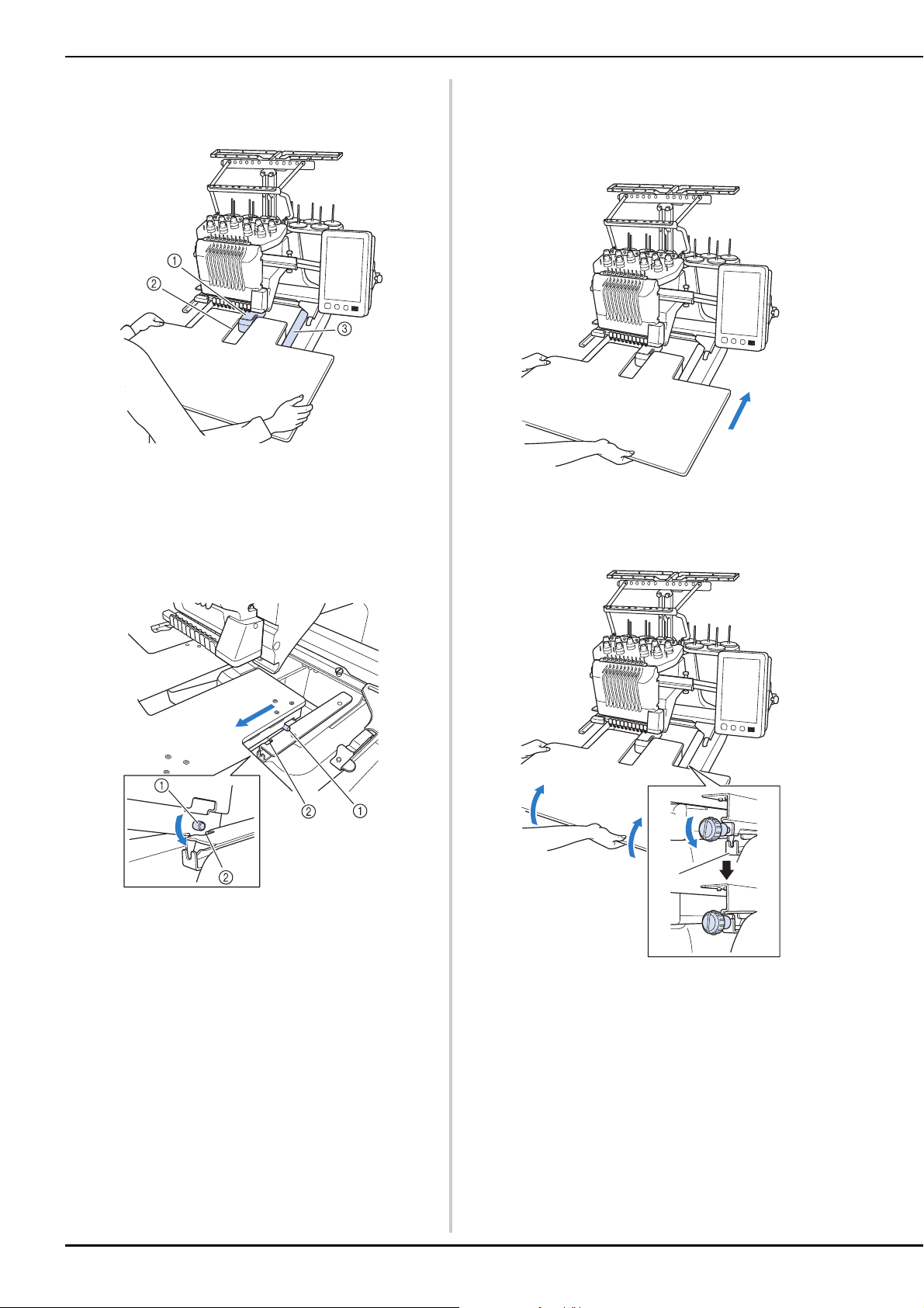
138
b
Position the wide table so that the notch at the center
aligns with the machine bed, and then place the wide
table flat on the guide plates.
1 Machine bed
2 Guide plate
3 Notch in wide table
c
Pull the wide table toward you until the pins on the
mounting brackets (attached on each side to the
bottom of the wide table) fit into the notches in the
guide plates.
1 Pin
2 Notch
d
Slide in the wide table while supporting it so that it
remains level. Push the wide table in until it lightly
touches the machine.
• If the wide table does not move smoothly, slightly lift
it up, and then slide it in.
e
While looking below the wide table, lightly lift it up,
and then lower it so that the screw fits into the notch at
the front of the guide plate.
1 Notch at front
a
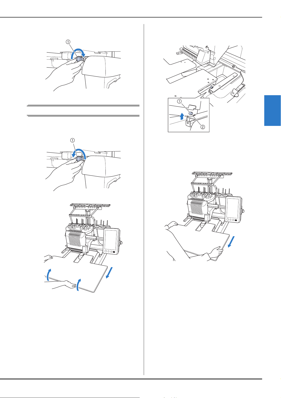
ADVANCED EMBROIDERY
139
3
f
Tighten the two thumb screws so that the wide table is
secured.
1 Thumb screw
Removing the wide table
a
Loosen the two thumb screws, lift up the wide table,
and then pull it off toward you.
1 Thumb screw
b
After the pins on each side reach the notches in the
guide plates, raise the wide table to lift the pins up
through the notches.
1 Pin
2 Notch
Remove the wide table from the machine.
c
Carefully pull out the wide table so that it does not hit
the machine.
d
Tighten the thumb screws on the wide table.
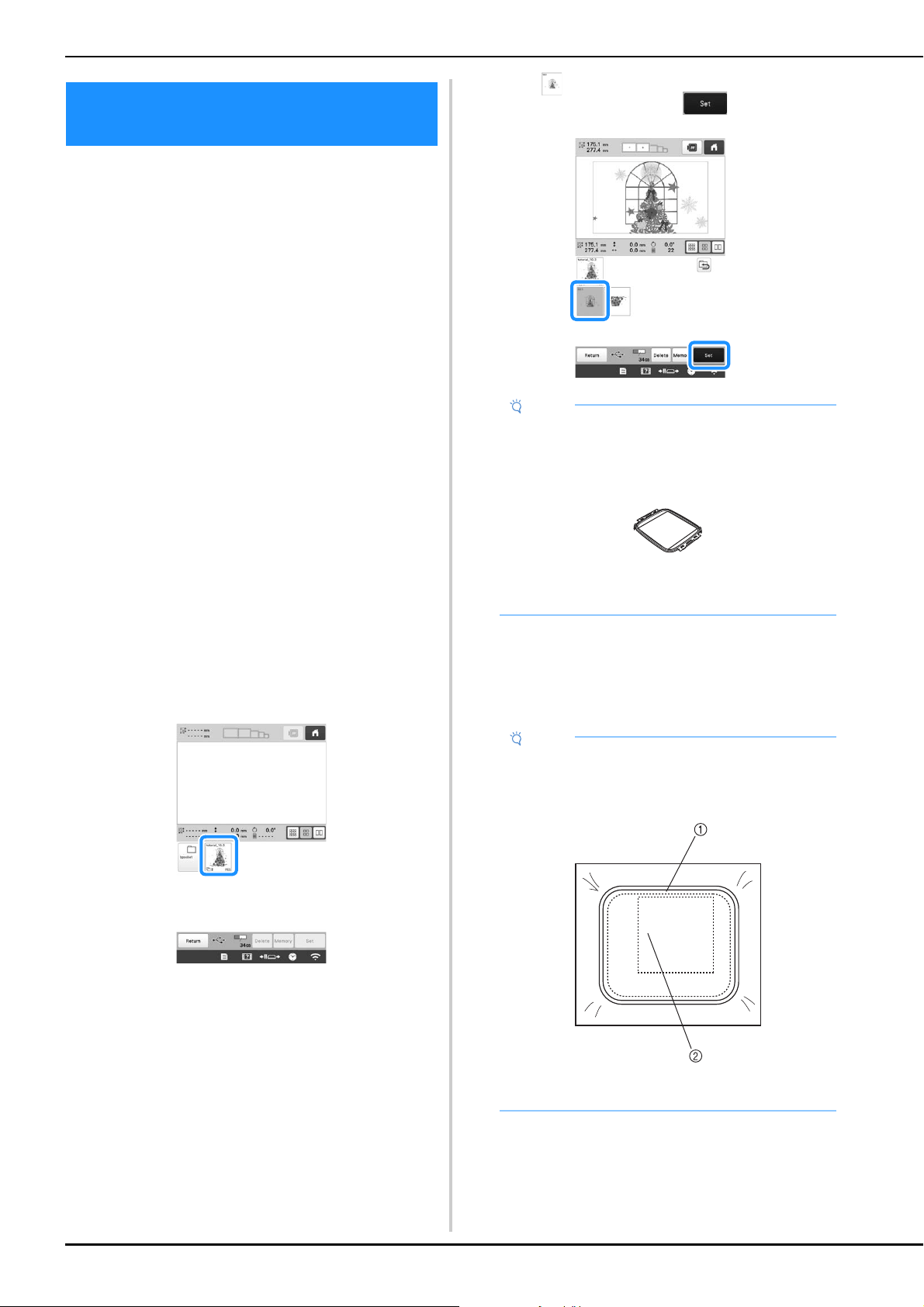
140
Patterns can be created in embroidery editing software
version PE-DESIGN NEXT or later to be used with the
Jumbo frame (optional).
When using the jumbo frame you must also use the
included wide table (PRWT1).
When a jumbo frame pattern is created in embroidery
editing software, the pattern is automatically divided into
two sections that can be combined into a single
embroidery design when it is embroidered with the jumbo
frame. When the jumbo frame is used, embroidery with a
maximum size of 350 mm × 350 mm (14 inches × 14
inches) can be embroidered without having to shift the
fabric within the frame.
For details on creating jumbo frame patterns, refer to the
Instruction Manual provided with the embroidery editing
software version PE-DESIGN NEXT or later.
After the jumbo frame pattern has been created, follow the
procedure described below to transfer the pattern to the
machine using external connection and begin
embroidering.
Jumbo frame patterns consist of a set of two patterns. To be
able to use them as a jumbo frame pattern, do not save
them in the machine's memory.
a
Connect the device containing the jumbo frame
pattern to this machine, and then select the jumbo
frame pattern from the pattern selection screen.
* For details on retrieving the pattern, refer to
page 130.
b
Touch to select the first section of the pattern to be
embroidered, and then touch .
c
Check the size of the pattern, and then hoop fabric that
is large enough in the optional jumbo frame.
* For details on attaching the optional jumbo frame,
refer to “Hooping the fabric in the embroidery
frame” on page 62.
EMBROIDERY PATTERNS FOR THE
OPTIONAL JUMBO FRAME
Note
• Before you start embroidering the jumbo frame
pattern, prepare the optional jumbo frame.
• Contact your authorized Brother dealer for
purchasing the optional jumbo frame.
• After hooping fabric or a garment, make sure that
the inner frame is lower than the outer frame so
that the frame sits flat against the extension table.
Note
• When hooping the fabric, position it within the
embroidery frame so there is at least 10 mm (3/8
inch) of space to the inside of the frame.
1 more than 10 mm (3/8 inch)
2 Location where the pattern is to be embroidered
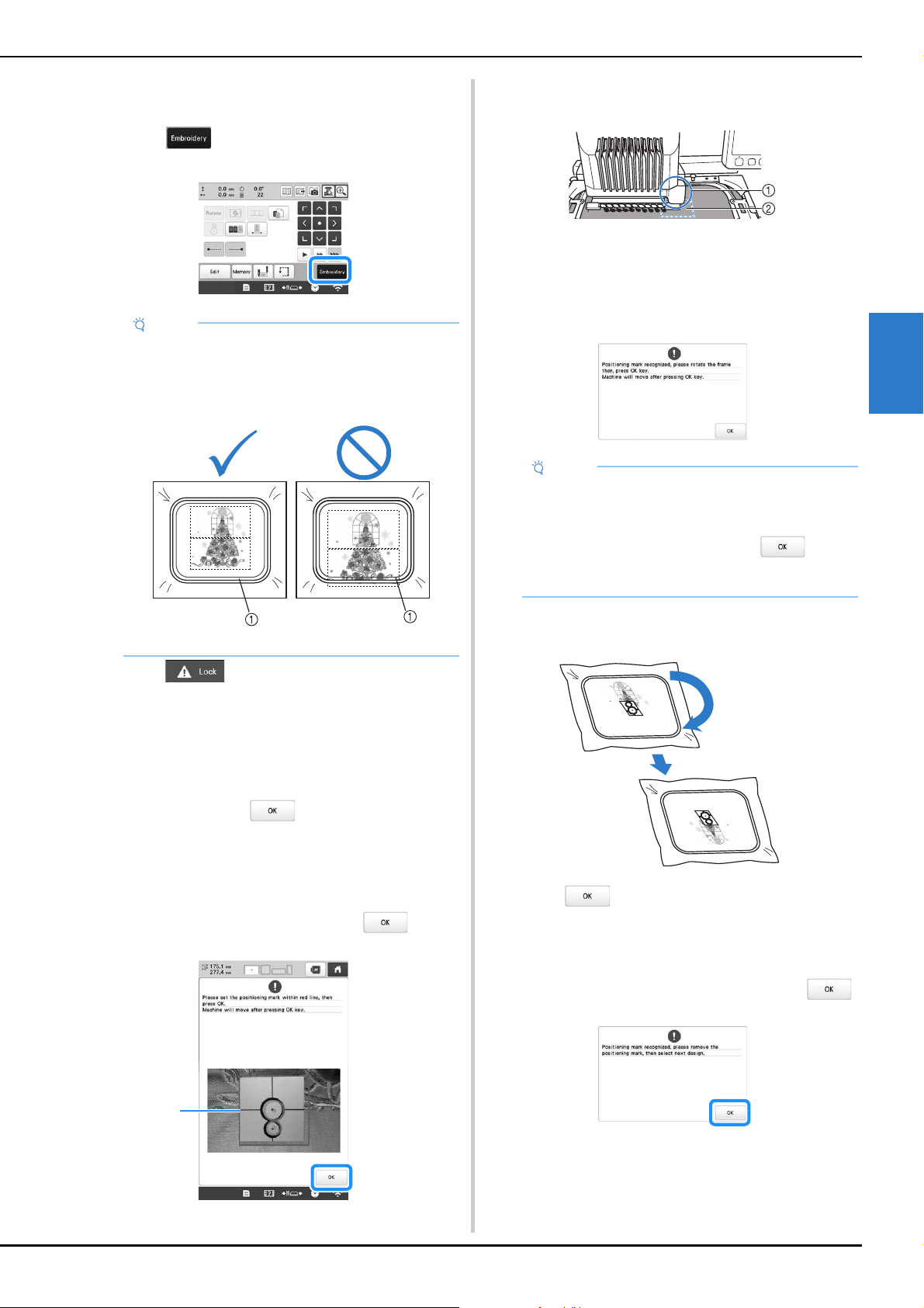
ADVANCED EMBROIDERY
141
3
d
Attach the jumbo frame to the machine.
e
Touch .
f
Touch , and then press the “Start/Stop”
button to start embroidering the first section of the
pattern.
g
After embroidering of the first section of the pattern is
finished, the message to confirm to embroider the next
part appears. Touch .
h
An image of the needle location appears in the screen
with the positioning detection area framed by a red
line. Affix an embroidery positioning sticker so that it
fits within the red line, and then touch .
1 Red line
• The positioning detection area is under the built-in
camera.
1 Built-in camera is in this box.
2 Affix the sticker in this area.
i
When the machine's built-in camera has finished
detecting the location of the embroidery positioning
sticker, the following message appears.
j
Remove the jumbo frame from the machine, turn the
frame around, and then attach it to the machine.
k
Touch , then the machine starts to detect the
location of the embroidery positioning sticker.
l
When the machine's built-in camera has finished
detecting the location of the embroidery positioning
sticker, the following message appears. Touch .
Note
• When you change the embroidering position using
the jumbo frame, be sure to be aware of the size of
the combined pattern. You cannot change the
position exceeding the embroidery area.
1 Embroidery area
1
Note
• If the built-in camera cannot detect the location of
the embroidery positioning sticker, the message
that could not recognize the embroidery
positioning sticker appears. Touch , and
then perform the procedure again starting from
step h.
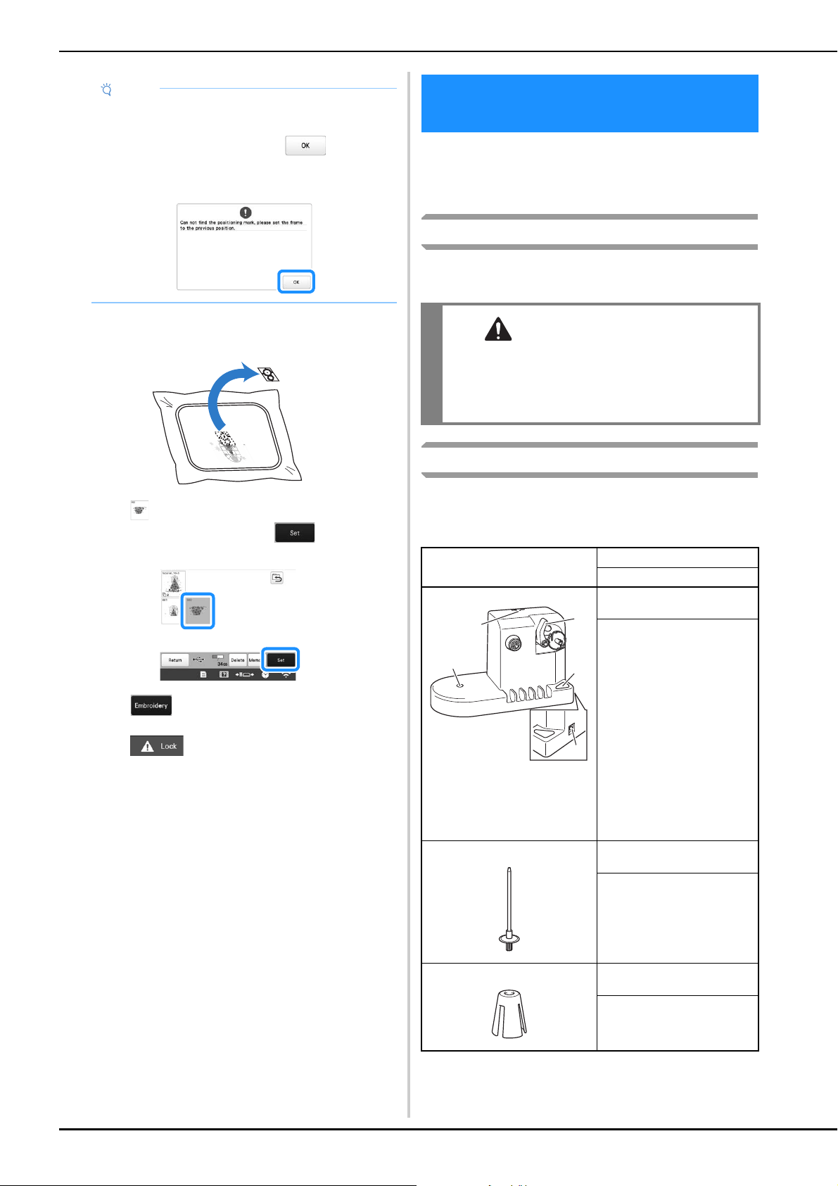
142
m
Remove the embroidery positioning sticker from the
fabric.
n
Touch to select the next section of the pattern to
be embroidered, and then touch .
o
Touch .
p
Touch , and then press the “Start/Stop”
button to start embroidering the next section of the
pattern.
When winding the bobbin thread onto a metal bobbin, use
the optional bobbin winder. The procedures for using the
optional bobbin winder are described below.
Precautions
For precautions concerning the power supply, refer to
page 22.
Optional bobbin winder and its accessories
Check that the following bobbin winder and accessories are
included. When the part code is “*”, contact your authorized
Brother dealer.
Note
• If the built-in camera cannot detect the location of
the embroidery positioning sticker, the following
error message appears. Touch , return the
jumbo frame to its previous orientation, and then
perform the procedure again starting from step
h.
USING THE OPTIONAL BOBBIN
WINDER
CAUTION
• Be sure to place the bobbin winder on a level,
stable surface.
• Be sure to use the bobbins supplied with this
bobbin winder.
Part Name
Part Code
1.
1 Main power switch
2 Bobbin winder shaft
3 Hole for thread guide
4 Hole for spool pin
5 DC input connector
Bobbin winder
PRBW1
2. Spool pin
XC5949-051
3. Spool cushion
XA0679-050
a
b
c
d
e
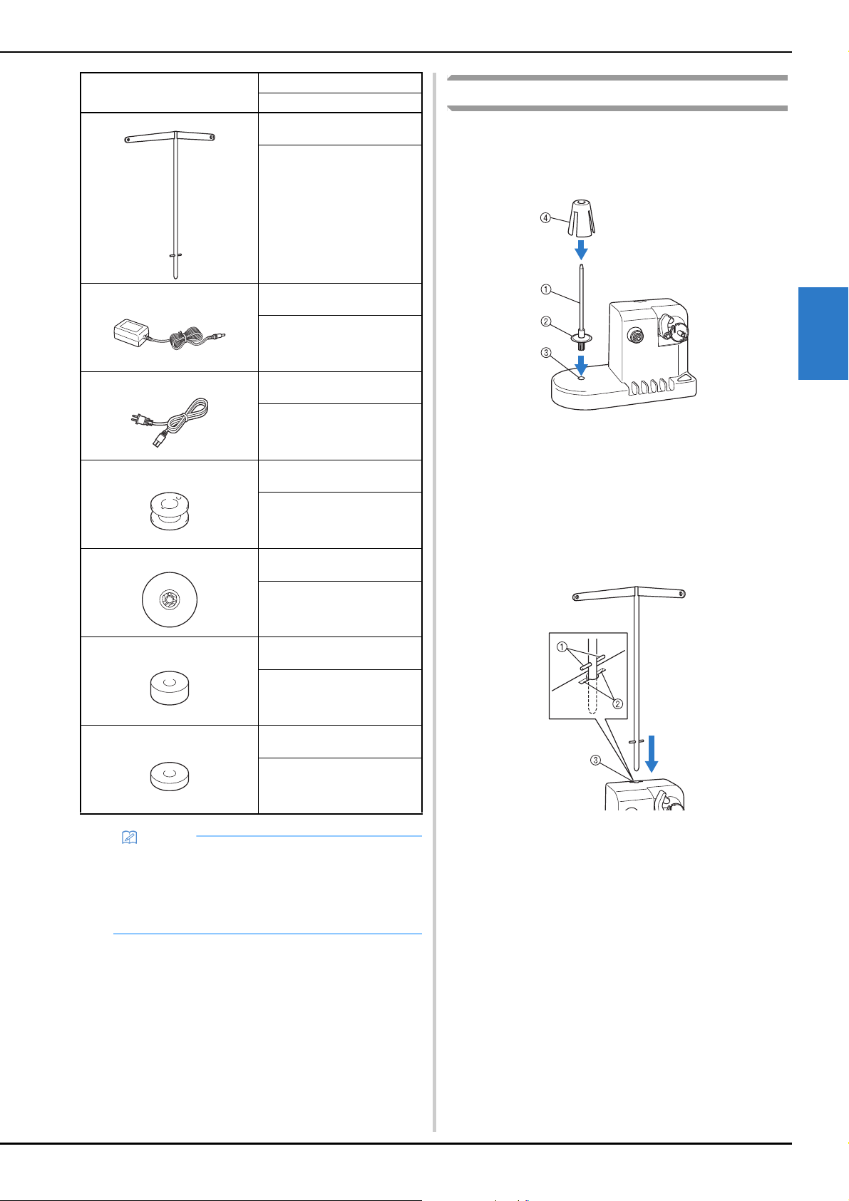
ADVANCED EMBROIDERY
143
3
Setting up the optional bobbin winder
a
Insert the spool pin and the spool cushion.
Lower the holder, and then insert the spool pin straight
into the hole. And insert the spool cushion.
1 Spool pin
2 Spool pin holder
3 Hole for spool pin
4 Spool cushion
b
Insert the thread guide.
Insert the thread guide straight into the hole with the
pins on the thread guide aligned with the notches on the
sides of the hole.
1 Pins on thread guide
2 Notches on hole for thread guide
3 Hole for thread guide
• Firmly insert the thread guide as far as possible and
make sure that it is secure.
4. Thread guide
XC6644-151
5. AC adapter
*
6. Power supply cord
*
7. Metal bobbin × 5
100376-051
8. Spool cap
130012-057
9. Weight (L)
XC5974-151
10. Weight (S)
XC6631-051
Memo
• The part code of the bobbin winder set may differ
depending on the country/area where the machine
was purchased.
• Depending on the model you purchased, the
bobbin winder may be included with the machine.
Part Name
Part Code

144
Connecting the AC adapter
a
Insert the plug of the power supply cord into the AC
adapter.
b
Plug the cord on the AC adapter into the DC input
connector of the bobbin winder, and then insert the
plug of the power supply cord into a household
electrical outlet.
• Be sure to firmly insert the plug on the AC adapter
into the DC input connector of the bobbin winder.
Winding the bobbin
Prepare the bobbin and the spool of bobbin thread. Use
cotton or spun polyester bobbin thread (from 74 dtex/2 to 100
dtex/2).
a
Align the groove in the bobbin with the spring on the
bobbin winder shaft, and set the bobbin on the shaft.
1 Groove in the bobbin
2 Spring on the shaft
b
Set the thread spool on the spool pin.
1 Thread spool
2 Spool pin
CAUTION
• Be sure to use the included AC adapter and
power cord of the bobbin winder.
• Before connecting or disconnecting the AC
adapter, be sure that the unit is not operating.
• After using the bobbin winder, disconnect it
from the electrical outlet.
Note
• When using a small spool, remove the spool
cushion and set the spool directly onto the spool
pin. Also use the included spool cap to keep the
small spool stable.
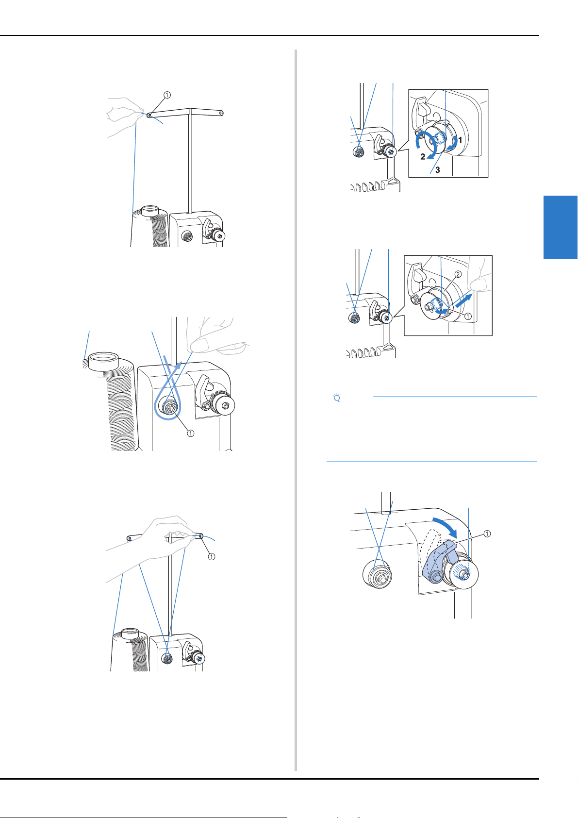
ADVANCED EMBROIDERY
145
3
c
Pass the thread through the hole in the left of the
thread guide toward the front of the winder.
1 Hole in the thread guide
d
Pass the thread around the tension disc as shown in the
illustration. Make sure that the thread is correctly fed
into the tension disc.
1 Tension disc
e
Pass the thread through the hole in the right of the
thread guide toward the back of the machine.
1 Hole in the thread guide
f
Wind the thread clockwise around the bobbin 4 or 5
times, as shown in the illustration.
g
Pass the end of the thread through the guide slit in the
bobbin winder seat, and pull the thread. The cutter will
cut the thread.
1 Guide slit
2 Bobbin winder seat
h
Slide the bobbin holder, until it clicks into place.
1 Bobbin holder
Note
• Be sure to follow the procedure described. If the
bobbin is wound without the thread being cut with
the cutter, when the bobbin thread runs low, the
thread may become tangled around the bobbin
and cause the needle to break.
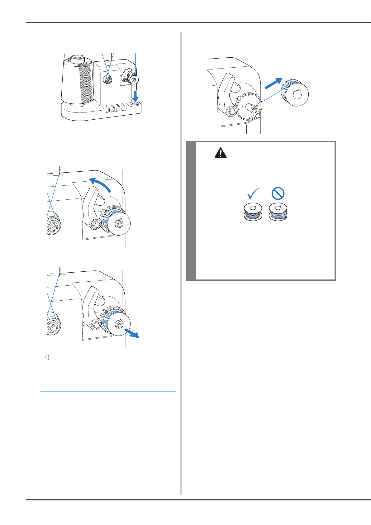
146
i
Press the main power switch to start winding the
bobbin.
Start winding the bobbin.
j
The bobbin will stop rotating automatically when it is
done winding, and the bobbin holder will return to its
original position.
k
Remove the bobbin.
l
Pull the thread through the guide slit in the bobbin
winder seat to cut the thread with the cutter.
■ If bobbin winding is stopped before it is
finished
The bobbin winder stops automatically if the thread does
not feed, for example, if it becomes tangled on the spool
pin. If this occurs, correctly thread the bobbin winder, and
then wind the bobbin correctly.
Note
• When removing the bobbin, do not pull on the
bobbin winder seat. Doing so could loosen or
remove the bobbin winder seat, resulting in
damage to the bobbin winder.
CAUTION
• Check that the bobbin thread has been wound
correctly, otherwise the needle may break or
the thread tension will be incorrect.
• Be sure to clean the bobbin case each time
that the bobbin is changed. For details, refer to
“Cleaning the bobbin case” on page 175.
• Be sure to check the tension of the bobbin
thread each time that the bobbin is changed.
For detailed instructions on how to adjust the
bobbin tension, refer to page 116.
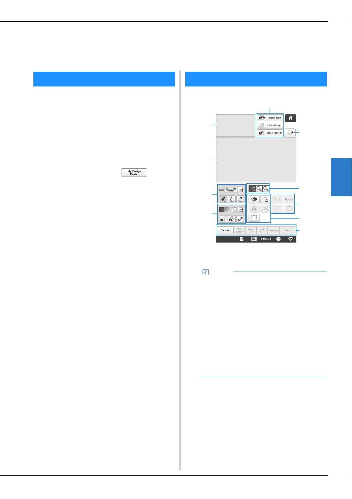
MY DESIGN CENTER
147
4
With My Design Center, you can use the functions listed
below:
• Hand-drawn functions - create embroidery patterns
by drawing on the LCD screen
• Scanning functions - create embroidery patterns by
not only scanning drawings /illustrations with built-in
camera, but also importing data from USB media or
computer.
You can also combine patterns that you have created with
the machine’s built-in patterns.
Start My Design Center by touching in the
pattern type selection screen.
1 Pattern drawing area
2 Pattern preview area
Chapter 4
MY DESIGN CENTER
ABOUT MY DESIGN CENTER PATTERN DRAWING SCREEN
Memo
• The actual dimension of the pattern area is the size
of the embroidery frame, which is 360 mm × 200
mm (approx. 14 inches × 7-7/8 inches). The pattern
you drew may be bigger than you expected. Please
resize the pattern after converting the design to the
embroidery pattern.
• When the pattern is enlarged so that only a part of
it appears in the pattern drawing area, the entire
pattern is displayed in the pattern preview area.
The red frame in the pattern preview area indicates
the part of the pattern displayed in the pattern
drawing area. Move the red frame in the pattern
preview area with the touch pen or your finger to
display the corresponding area in the pattern
drawing area.
3
6
0
4
5
1
2
8
7
9
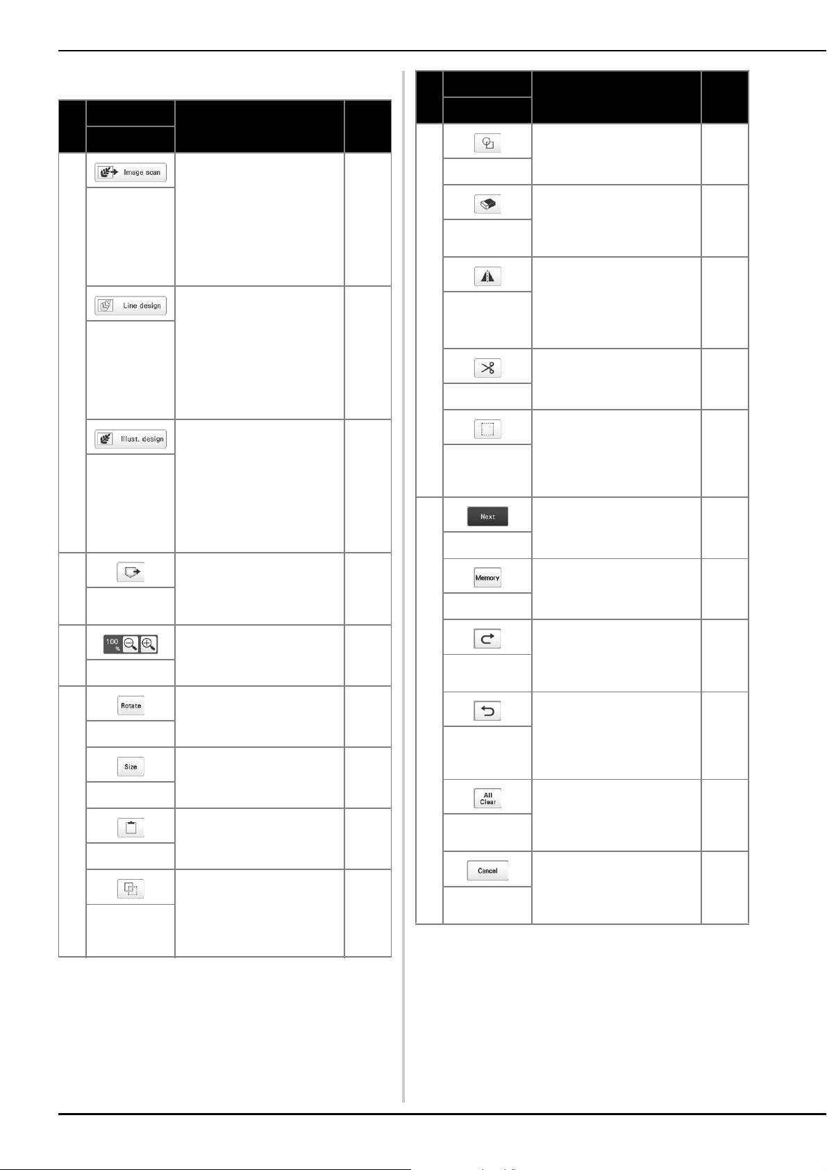
148
■ Key Functions
No.
Display
Explanation Page
Key Name
3 Scan the attached frame and
display on the screen as the
background while using the
My Design Center. You can
scan the fabric as the
background or scan the
picture as the reference when
creating the pattern.
158
Image scan
key
Scan the line drawing to edit
and convert to the
embroidery data using the
built-in camera. You can also
import the line drawing
image from USB media or
computer and create the
embroidery design.
160
Line design
key
Scan the illustration to edit
and convert to the
embroidery data using the
built-in camera. You can also
import the illustration from
USB media or computer and
create the embroidery
design.
162
Illustration
design key
4 Recall pattern data created
with My Design Center from
the machine’s memory, USB
media or the computer.
—
Recall key
5 Magnify the pattern. 151
Magnify key
6 Rotate the selected section. —
Rotate key
Change the size of the
selected section.
164
Size key
Paste in the previously
duplicated or cut section.
—
Paste key
Duplicate the selected
section. The temporarily
positioned section can
immediately be rotated,
enlarged, reduced or moved.
—
Duplicate key
7 Select the stamp shape for
pattern drawing.
152
Stamp key
Erase lines and shapes that
have been drawn. You can
select the size/shape of the
eraser.
153
Erase key
Flip the selected section
horizontally.
—
Horizontal
mirror image
key
Cut out the selected section. —
Cut key
Select a section by finger or
pen for moving, copying,
deleting, changing size and
rotating lines and shapes that
have been drawn.
153
Select key
8 Continue to the stitch settings
screen.
—
Next key
Store the pattern being
created.
—
Memory key
Redo the operation that was
undone with the undo key.
Each touch of this key will
redo one operation.
—
Redo key
Undo the last operation that
was performed and return to
the previous state. Each
touch of this key will undo
one operation.
—
Undo key
Clear all the lines and shapes
and start from the beginning.
The background image is
also cleared.
—
All clear key
Exit from the My Design
Center. All lines and shapes
are erased when you touch
this key.
—
Cancel key
No.
Display
Explanation Page
Key Name
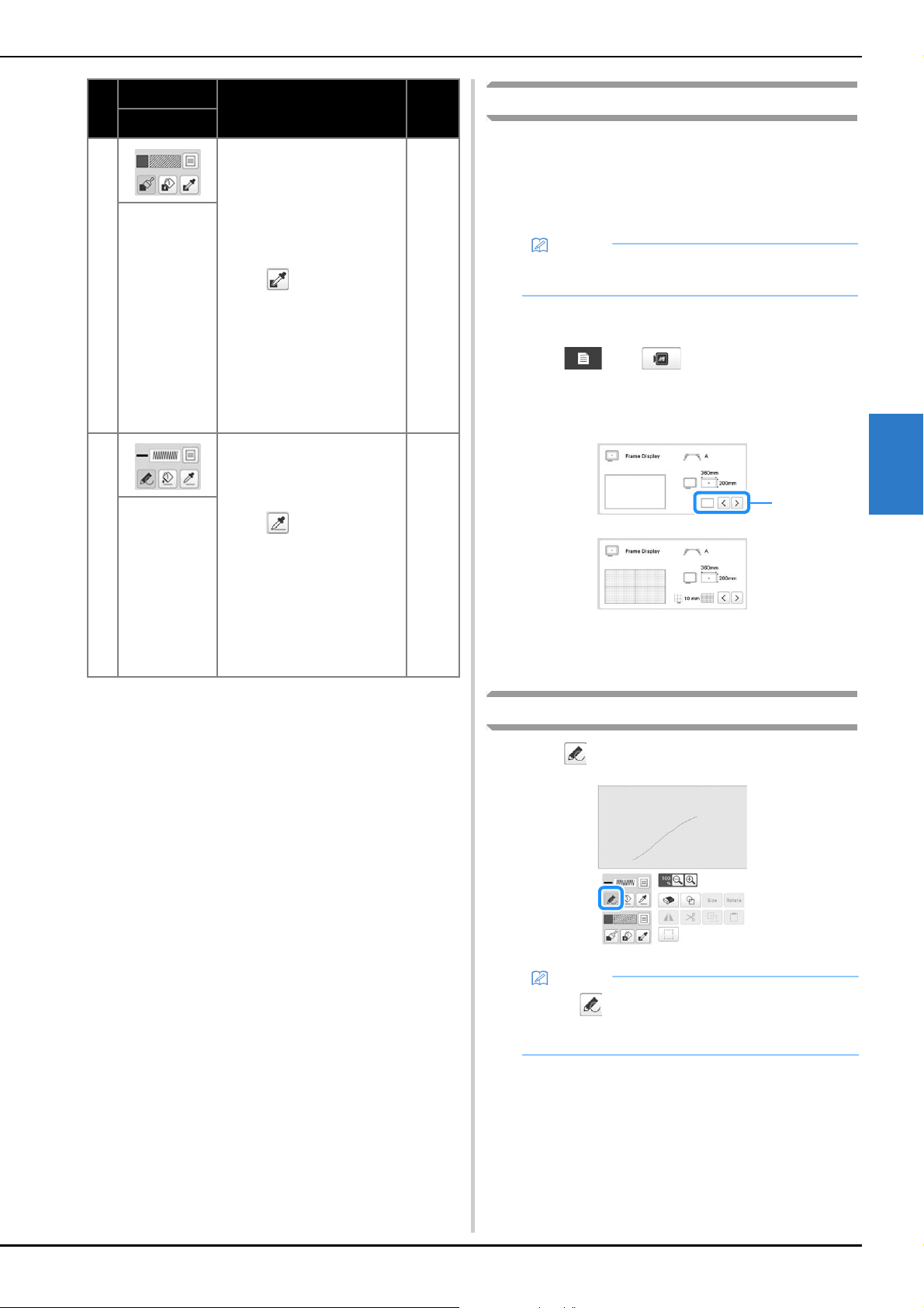
MY DESIGN CENTER
149
4
Before creating designs
Select the center point marker or grid lines setting for [Frame
Display] to apply the frame display to the pattern drawing
area of My Design Center.
For details on the types of embroidery frames and grids
available, refer to “Changing the display guides” on page 123.
a
Attach the frame to be used.
b
Touch , then .
The embroidery settings screen appears.
c
Select the grid line of the [Frame Display].
1 Grid types
* Select the grid size 10 mm (3/8 inch) or 25 mm (1
inch).
Drawing lines
a
Touch and draw lines.
9 Paint with brush and set the
color. You can select the
brush type, fill type and color
as you need. Painted lines
and areas will be converted
to the pattern embroidered
with fill stitch.
Touch to pick up the
color and fill type from a
region in the pattern within
the pattern drawing area. The
picked up color is shown as
the currently selected region
color beside the button and
as the selected color in the
Region Property screen.
151
Brush tool key
0 Draw lines and set the color.
You can select the line type,
stitch type and color as you
need.
Touch to pick up the
color and stitch type from a
line in the pattern within the
pattern drawing area. The
picked up color is shown as
the currently selected line
color beside the button and
as the selected color in the
Line Property screen.
149
Line tool key
No.
Display
Explanation Page
Key Name
Memo
• The frame type cannot be changed in the settings
screen.
Memo
• When is touched, all regions will be displayed
in the background to clarify the drawing lines on
the screen.
1
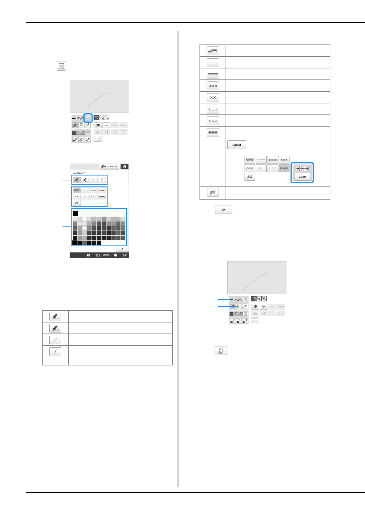
150
■ Setting the line types, stitch types and colors
You can set or change the line types, stitch types and
colors anytime. You can also specify the line types, stitch
types and colors before drawing lines.
a
Touch to set the line types, stitch types and colors.
The settings screen appears.
1 Line types
2 Stitch types
3 Line color selection: touch the color palette to activate
the drawing pen color.
Line types
Stitch types
b
Touch to return to the pattern drawing screen.
The color bar on the line tool key is changed to the
selected color.
* The appearance of the line does not change even if
the stitch type was changed. The specified stitch
type can be checked in the stitch settings screen.
1 Color bar
2 Stitch type
c
Touch , and then touch on the line to change its
color.
The connected line will be changed to the selected
color.
Freehand line with the end open.
Freehand line closing the end automatically.
Straight line with one stroke
Straight line changing directions to the point
you select. If the end point is created near the
start point, a closed object will be created.
1
2
3
Zigzag stitch
Running stitch
Triple stitch
Candlewicking stitch
Chain stitch
E stitch
V stitch
Select motif stitches
Displays motif stitch selection screen, where
can be touched to select a pattern.
Line without stitch for creating a region.
Created region will be defined by the gray line.
2
1
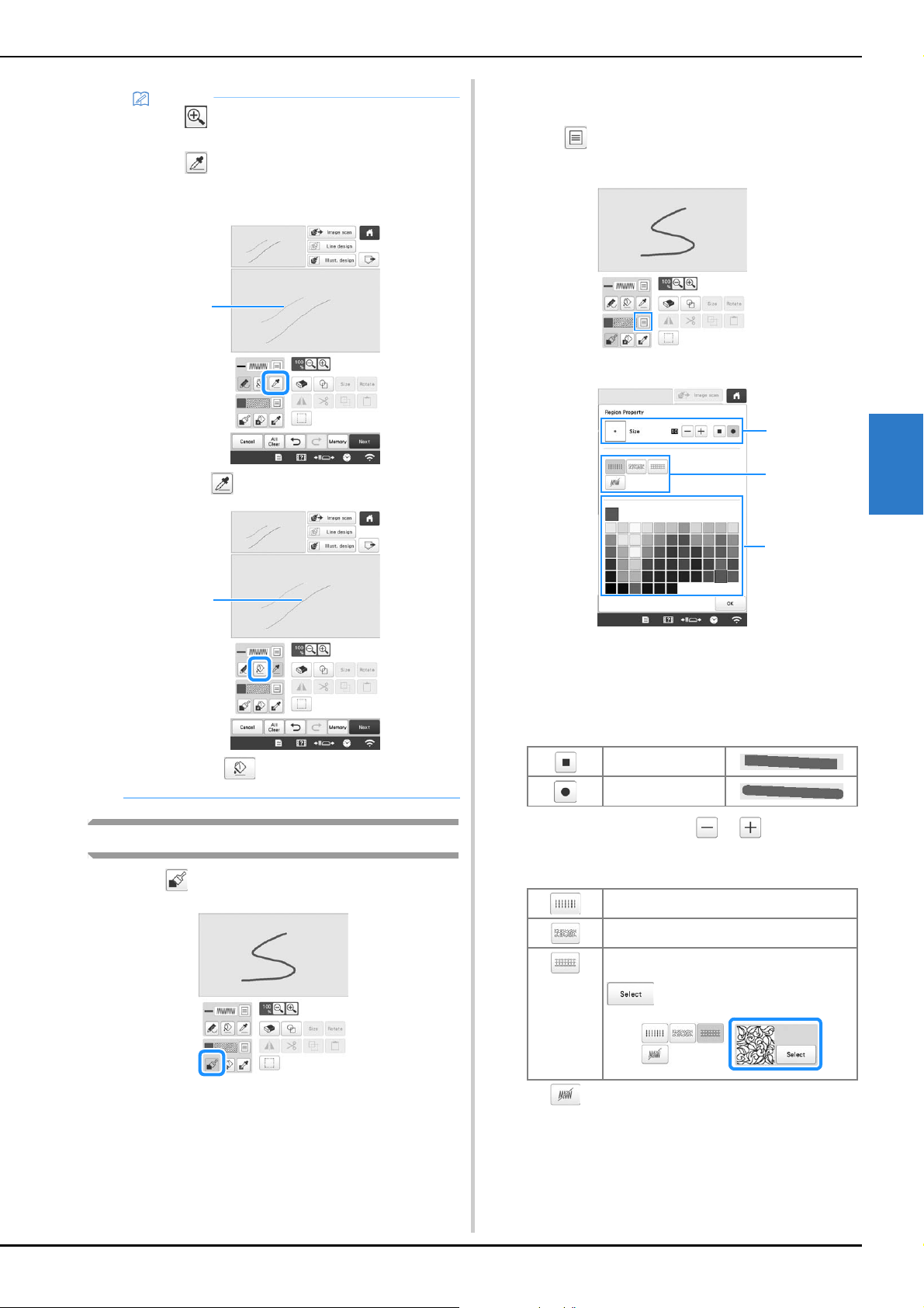
MY DESIGN CENTER
151
4
Drawing regions
a
Touch and draw with brush.
■ Setting the brush types, fill patterns and fill
colors
a
Touch to set the brush types, fill patterns and fill
colors.
The setting screen appears.
1 Brush types
2 Fill stitch types
3 Fill color selection: touch the color palette to activate the
paint brush color.
Brush shapes/sizes
To select the brush size, touch or .
Fill stitch types
Select when you don’t want fill stitches.
Memo
• Touch to magnify the image when you cannot
touch on the line correctly.
• Touch , and then select a color within the
pattern drawing area to apply the same color to
other lines or parts of the pattern.
1 Use to select the line color.
2 Touch for changing the line color, and then
select the pattern to be changed.
1
2
Square brush
Round brush
Fill stitch
Stippling stitch
Decorative fill stitches
Displays a stitch selection screen, where
can be touched to select a stitch.
1
3
2
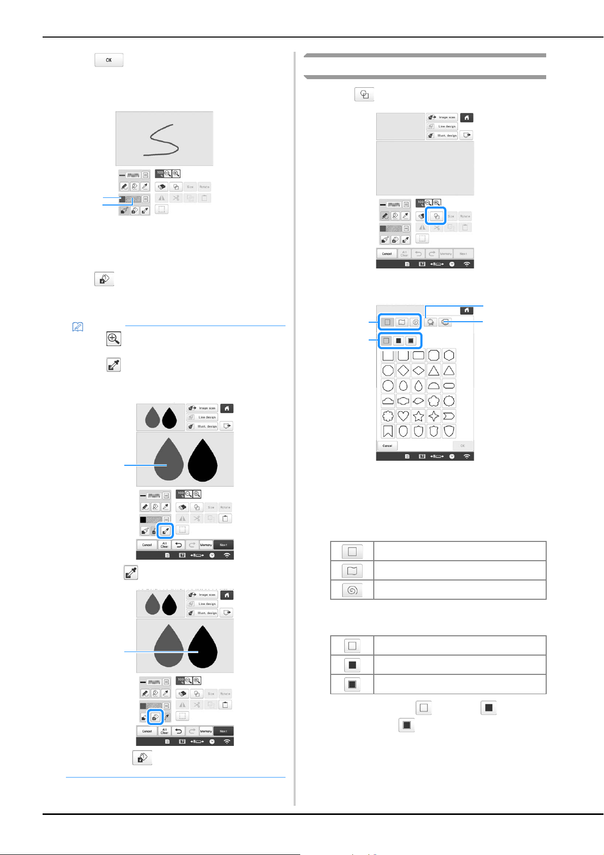
152
b
Touch to return to the pattern drawing screen.
The color bar on the brush tool key is changed to the
selected color.
1 Color bar
2 Fill stitch type
* If a stippling pattern or decorative fill pattern has
been specified, the settings are displayed.
c
Touch and touch on the brush line to change
color and fill stitch type. You can also set the color and
fill stitch type of a closed region made of the line.
Using the stamp key
a
Touch .
b
Select a stamp type and stamp shape.
1 Stamp shapes
2 Stamp types
3 Saved outlines
4 Frame embroidering areas
Stamp shapes
Stamp types (Only for Basic shapes)
* Select the outline ( ), fill stitch ( ), or outline
and fill stitch ( ) of a basic shape.
Memo
• Touch to magnify the image when you cannot
touch on the fill correctly.
• Touch , and then select a pattern color in the
pattern drawing area to apply that fill color to other
patterns.
1 Use to select the fill color.
2 Touch for changing the fill color, and then
select the pattern to be changed.
1
2
1
2
Basic shapes
Closed shapes
Open shapes
Outline
Fill stitch
Outline and fill stitch
3
2
4
1
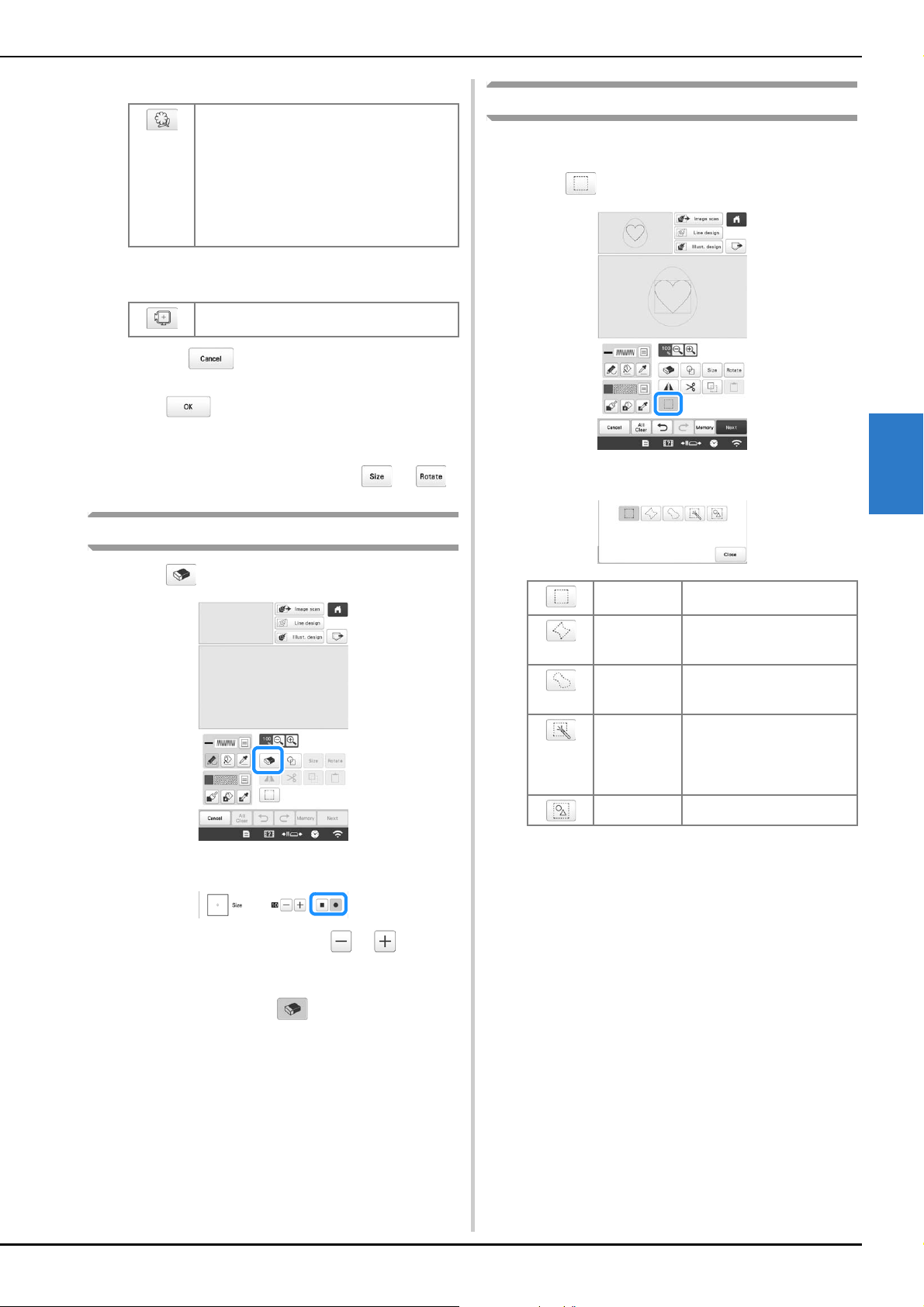
MY DESIGN CENTER
153
4
Saved outlines
Frame embroidering areas
* Touch to return to the pattern drawing
screen.
c
Touch to set the selected stamp.
The pattern drawing screen appears.
* You can change size of, rotate or move the shape
right after you create it by touching or .
Using the erase key
a
Touch .
b
Select the shape of the eraser.
To select the eraser size, touch or .
c
Drag along the area or line that you want to erase
while the key appears as .
Using the select key
You can select the part of the design to move and/or edit.
Some keys are available only after you select the part.
a
Touch .
b
Select the method for selecting an area.
Embroidery pattern outlines can be registered
as stamp shapes. When registering stamp
shapes, select from the last six embroidery
patterns used. If more than six shapes are
registered, the oldest one is automatically
erased. For details on registering a stamp
shape, refer to “Decorative stitching around a
pattern in embroidery (a quilting function)” on
page 170.
The shape of the embroidering area for the
selected embroidery frame is displayed.
Box selection
Selects all objects within the
box that is drawn.
Polygonal
shape
selection
Selects all objects within the
polygonal shape that is drawn.
Freestyle
curve
selection
Selects all objects within the
curved line that is drawn.
Automatic
selection
Selects the pattern that is
touched. This allows you to
select only a single line or only
the outer pattern of a donut
shape.
Select all Selects all patterns.
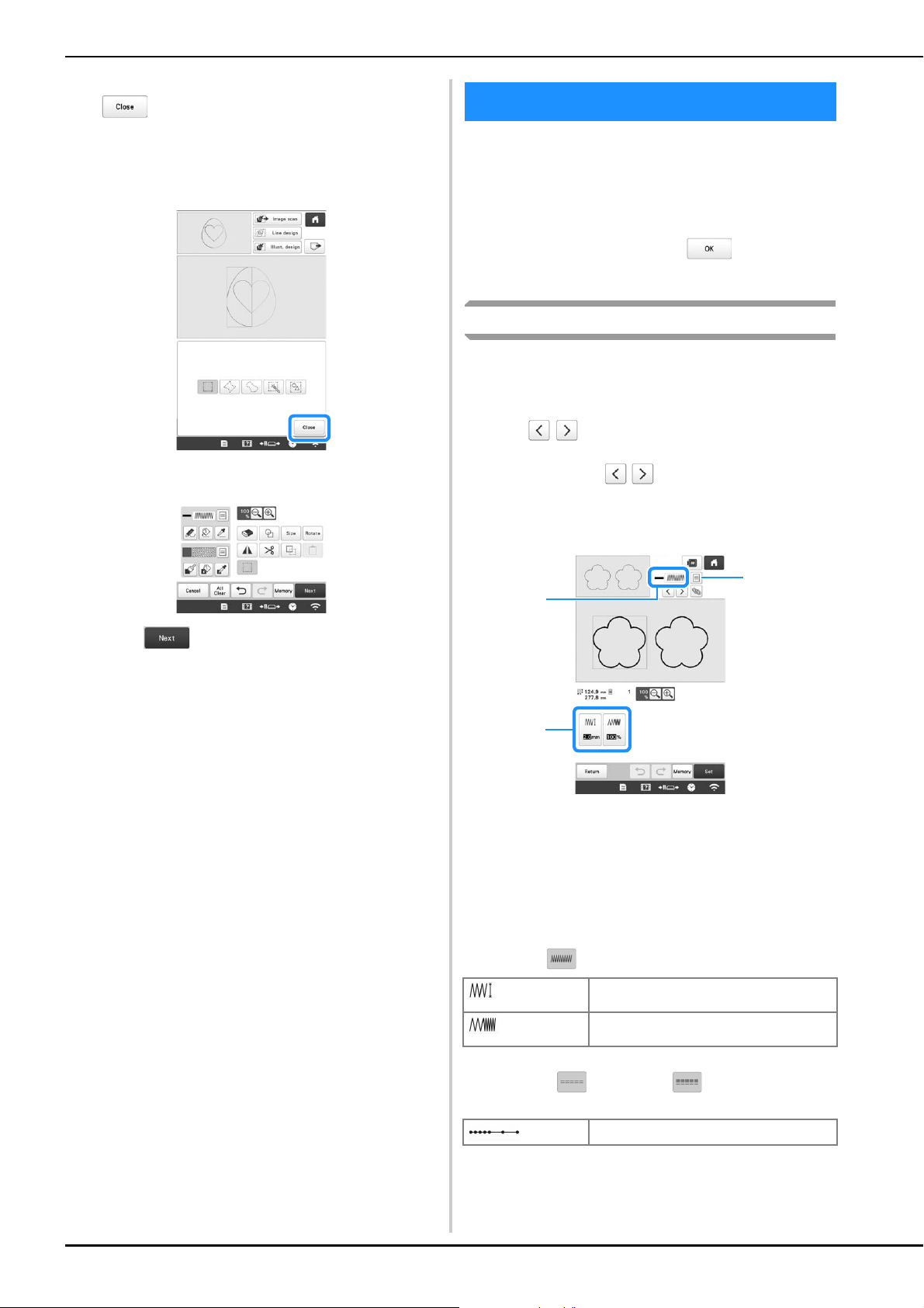
154
c
Select the area you want to edit, and then touch
.
* To select an area you want to edit, hold the touch
pen at a point on the screen and drag the touch pen
to create the red box around your selected area to
be edited.
d
Edit the design with available keys. (page 148)
e
Touch , and then specify the stitch setting.
Before creating the embroidery pattern, specify the stitch
settings. Lines of the design are embroidered with various
stitches and regions are embroidered with fill stitches or
stippling stitches. Stitching of the regions was already
selected in “Drawing regions” on page 151, so specify
values of detailed settings.
After specifying the settings, touch to create the
embroidery pattern.
Specifying individual stitch settings
Select a pattern in the stitch settings screen to specify its line
and region stitch settings. If multiple patterns are selected, the
settings are applied to those patterns.
a
Use to select the line or region to be changed.
Each touch of moves the highlighting of the
selected pattern in order.
■ Line settings
1 Shows the stitch type and color for the selected line.
2 Shows/Changes the stitch settings for the selected line.
3 Choices for stitch type and color of selected line.
Line stitch settings
Select the type of stitching you want applied to your line
art.
Zigzag stitch
Running stitch /Triple stitch
* Both includes an under embroidery.
STITCH SETTINGS SCREEN
[Zigzag width]
Specifies the width of the zigzag stitches
used to embroider the lines of the design.
[Density]
Specifies the density of the zigzag stitches
used to embroider the lines of the design.
[Run Pitch] Specifies the length of the stitch.
2
1
3
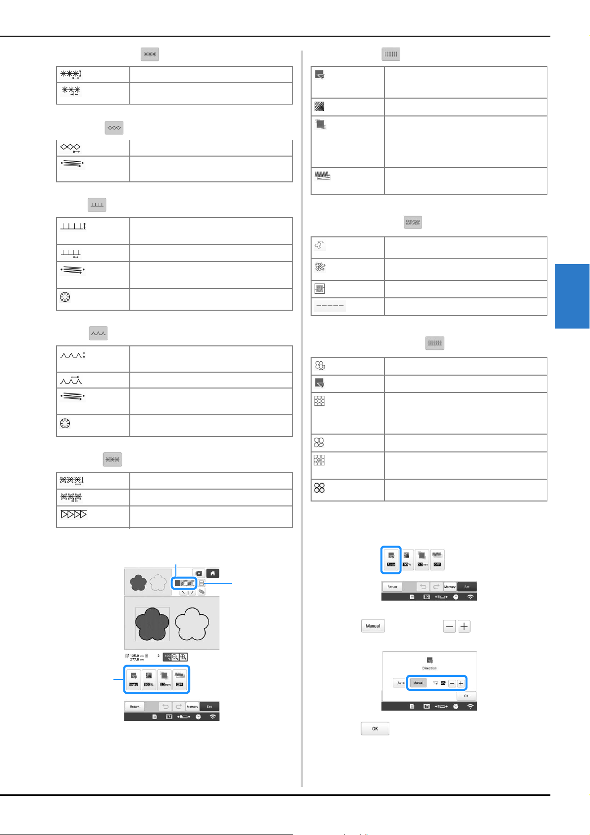
MY DESIGN CENTER
155
4
Candlewicking Stitch
Chain stitch
E stitch
V stitch
Motif stitch
■ Region Settings
1 Shows the stitch type and color for the selected region.
2 Shows/Changes the stitch settings for the selected
region.
3 Choices for stitch type and color of selected region.
Fill stitch settings
Stippling stitch settings
Decorative fill stitch settings
b
Select the setting to be changed, and then change the
setting in the screen that appears. (In this example, the
embroidering direction will be changed.)
The setting screen appears.
c
Touch , and then use to change the
direction.
d
Touch to apply the setting.
* Change other settings in the same way.
[Size]
Increases/reduces the size of the stitch.
[Spacing]
Specifies the spacing of the candlewicking
stitch.
[Size]
Increases/reduces the size of the stitch.
[Thickness]
Sets repeated embroidering at the same
part.
[Stitch
Width]
Increases/reduces the size of the stitch.
[Spacing]
Specifies the spacing of the E stitch.
[Thickness]
Sets repeated embroidering at the same
part.
[Flip]
Specifies the decorative line showing up to
the inside or to the outside.
[Stitch
Width]
Increases/reduces the size of the stitch.
[Spacing]
Specifies the spacing of the V stitch.
[Thickness]
Sets repeated embroidering at the same
part.
[Flip]
Specifies the decorative line showing up to
the inside or to the outside.
[Size]
Increases/reduces the size of the stitch.
[Spacing]
Specifies the spacing of the motif stitch.
[Flip]
Specifies the decorative line showing up to
the inside or to the outside.
3
2
1
[Direction]
Specifies the embroidering direction. Select
[Manual] to change to the desired direction of
fill stitch.
[Density]
Specifies the stitch density of fill stitch.
[Pull
compensation]
Specifies to correct the shrinkage of the
pattern by slightly shortening or lengthening
the stitching. Change the setting after you
test embroidering the pattern and can check
the shrinkage.
[Under
sewing]
Select if you need or do not need the under
embroidery for the stabilized fabric.
[Run Pitch]
Specifies the length of a stitch of the
stippling stitch.
[Spacing]
Specifies the spacing between the stitches
when embroidering the stippling stitch.
[Distance]
Specifies the offset from the pattern outline.
[Stitch]
Specifies the stitch type.
[Size]
Increases/reduces the size of the pattern.
[Direction]
Specifies the rotation angle of the pattern.
[Outline]
Select whether [ON] or [OFF]. The outline is
also converted to embroidery data. If [ON] is
selected, the number of thread jumps can be
reduced.
[Random shift]
Randomly varies the line.
[Position
Offset]
Specifies the reference point for the pattern.
[Thickness]
Sets repeated embroidering at the same
part.
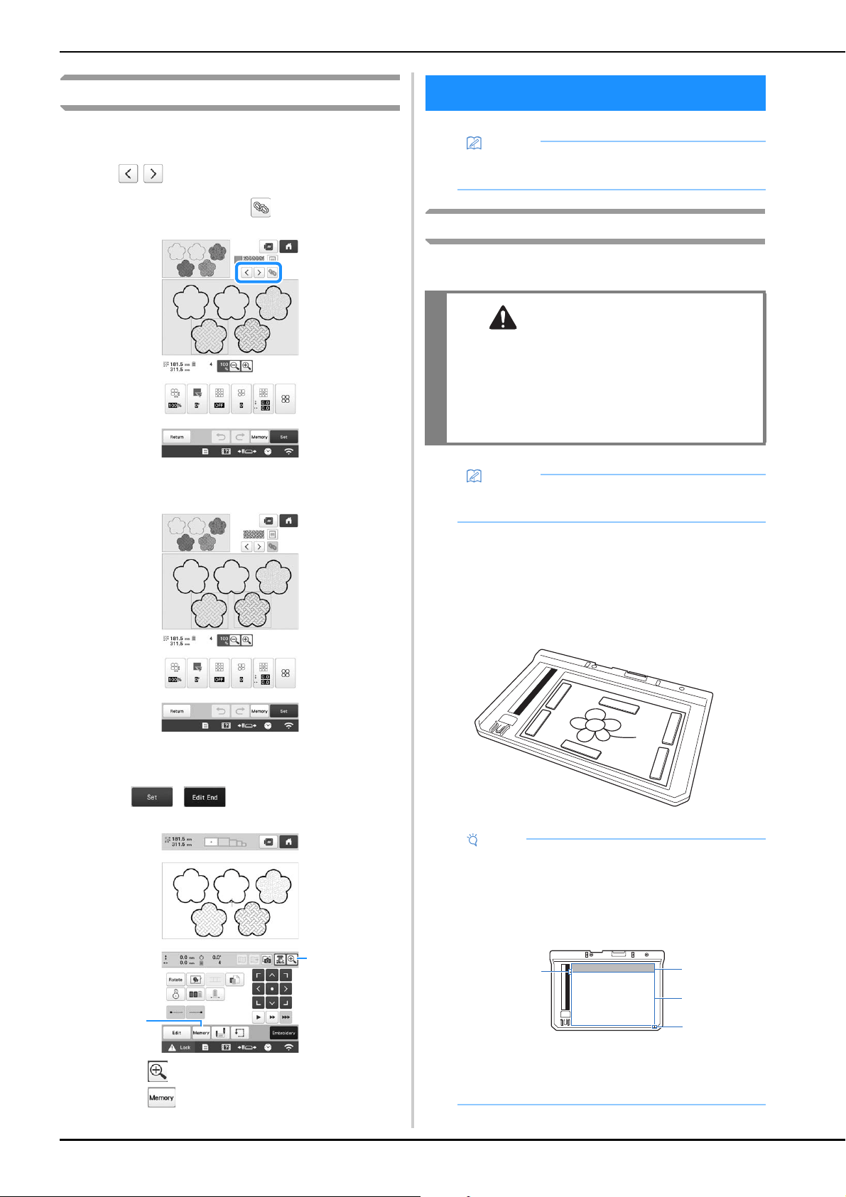
156
Specifying global stitch settings
The same stitch settings can be changed at the same time for
multiple patterns of the same type.
a
Use
to select the stitch whose settings are to
be changed, and then touch .
The same stitch type areas will be selected at the
same time.
b
Follow steps b through d in “Specifying individual
stitch settings” on page 154 to change the settings.
c
Touch , to display the embroidering
settings screen.
1 Touch to check an enlarged view of the pattern.
2 Touch to save the embroidery data.
Attaching the scanning frame
a
Prepare the desired drawing/illustration.
b
Position the paper to be scanned so that it is aligned
with the lower-left corner, securing the paper in place
with the magnets.
* Place the magnets at six locations around the paper
to secure it, making sure that the line drawing is not
covered.
1
2
MY DESIGN CENTER WITH SCAN
Memo
• The scanning frame is an optional accessory in
some countries or regions.
CAUTION
• To avoid having the embroidery foot strike the
frame during the scanning process and
possibly causing injury, check the following:
the thickness of the fabric or paper, creases or
folds in the fabric or paper that may be rolled
up too close to the frame.
Memo
• Only one sheet of paper can be placed in the
scanning frame per scan.
Note
• The scanning area is 300 mm × 200 mm (approx.
11-3/4 inches × 7-7/8 inches). There are scan area
marks within the frame. Make sure that the paper is
placed within the mark. Any part of the image that
is outside the mark will not be scanned.
1 300 mm × 200 mm (approx. 11-3/4 inches × 7-7/8
inches) mark (maximum scanning field)
2 Scan area
3 Outside the scan area
2
3
1
1
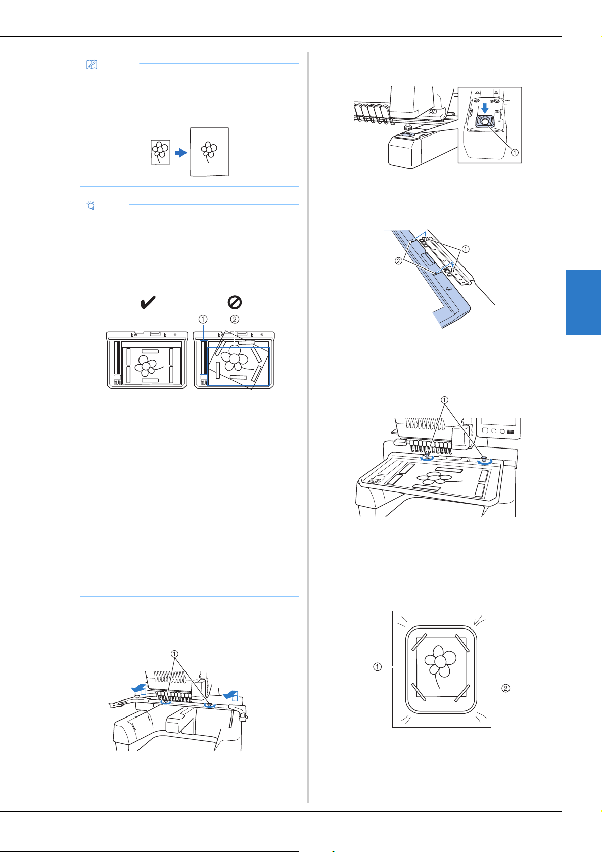
MY DESIGN CENTER
157
4
c
Remove the two thumb screws securing the
embroidery frame holder, and then remove the frame
holder from the machine.
1 Thumb screws
d
Install the needle plate cover included with the
machine.
1 Needle plate cover
e
Align the holes in the scanning frame with the pins on
the frame-mounting plate of the carriage.
1 Pins on the frame-mounting plate
2 Holes in the scanning frame
f
Secure the scanning frame with the two thumb screws
removed in step
c.
1 Thumb screws
■ Scanning with an embroidery frame
Drawings and illustrations can also be scanned using an
embroidery frame. Hoop the embroidery frame with fabric
larger than the frame. Place the paper to be scanned on
the fabric, and then secure it, with tape.
1 Fabric
2 Tape
Memo
• If you want to scan an image from a small piece of
paper that can't be held with the magnets, copy
that image onto a larger piece of paper, and then
place it on the scanning frame.
Note
• When placing the paper in the scanning frame,
make sure that the white balance area is not
hidden; otherwise, the drawing cannot be scanned
correctly. At the same time, be sure to place the
scan image within the scan area. The image out of
the scan area will not be scanned.
1 White balance area
2 Scan area
• Make sure that the white balance area or the scan
area is not dirty or scratched; otherwise, the image
cannot be scanned correctly.
• Use the magnets which are included with the
scanning frame. If any other magnets are used,
they may become attached to the machine during
scanning, or other problems, such as a misaligned
scan image, may occur.
• Be sure to place the magnets so that they secure
the paper firmly. If the paper is placed unevenly,
the image cannot be scanned correctly.
• If the scanning frame is dirty, wipe it with a cloth
dampened with a diluted neutral detergent
solution.
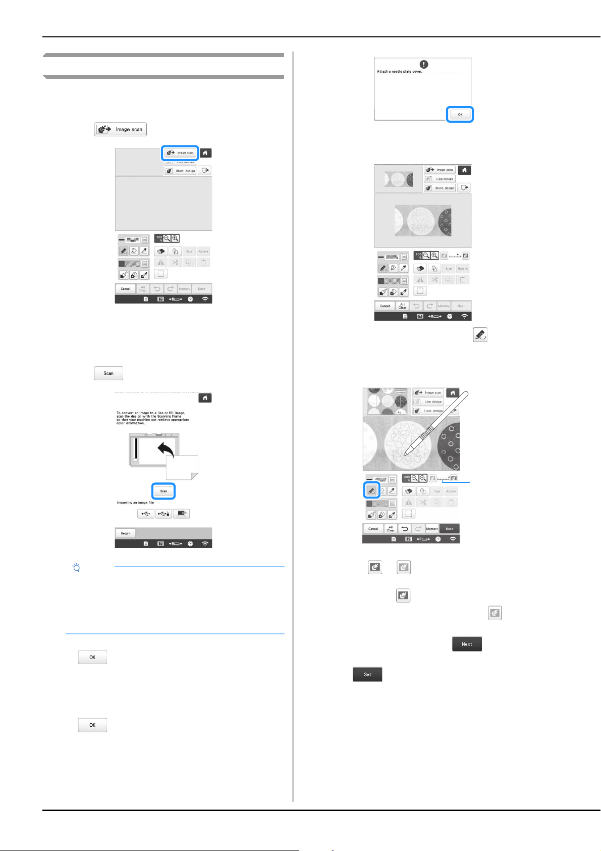
158
Scanning to trace background image
If you have a favorite picture or drawing, it can easily be
traced on the scanned background image and you can create
your own pattern.
a
Touch .
The image display screen appears.
b
Using the magnets, affix a picture to the scanning
frame and attach the frame to the machine. Refer to
“Attaching the scanning frame” on page 156.
c
Touch .
When the message to start scanning appears, touch
.
Scanning starts.
If the following message appears, remove the
scanning frame, install the needle plate cover, and
then re-install the scanning frame, and then touch
.
d
When scanning is finished, scanned image is displayed
transparently in the pattern drawing area.
e
Using the included touch pen, touch , and then
draw lines to trace the image.
* For details on drawing lines, refer to “Drawing lines”
on page 149.
1 Transparency adjustment
* Touch or to adjust the transparency of the
background.
Each touch of lightens the background, making
the line pattern darker. Each touch of darkens
the background, making the line pattern lighter.
f
After editing the pattern, touch to specify the
settings for pattern.
g
Touch to display the pattern editing screen.
Note
• When scanning starts, some of the machine lights
will turn off in certain circumstances, in order to
increase the scan quality. The machine lights will
return to their original brightness when scanning
ends.
1
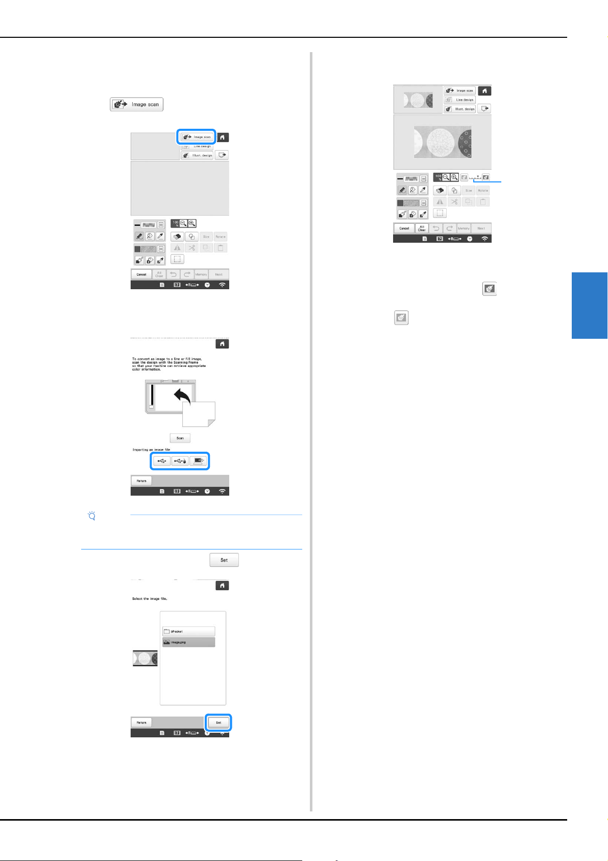
MY DESIGN CENTER
159
4
■ Importing the background image
You can import an image as a background from computer
or USB media.
a
Touch .
The image display screen appears.
b
Select the device you saved the data to.
c
Select the data, and then touch .
d
The selected image is displayed transparently in the
pattern drawing area.
* After the scanned image is converted to stitching, it
appears as a background in the pattern drawing
screen. Use gauge 1 to adjust the transparency of
the background. Each touch of lightens the
background, making the line pattern darker. Each
touch of darkens the background, making the
line pattern lighter.
Note
• You can import an image of 2 MB or smaller from
computer or USB media.
1
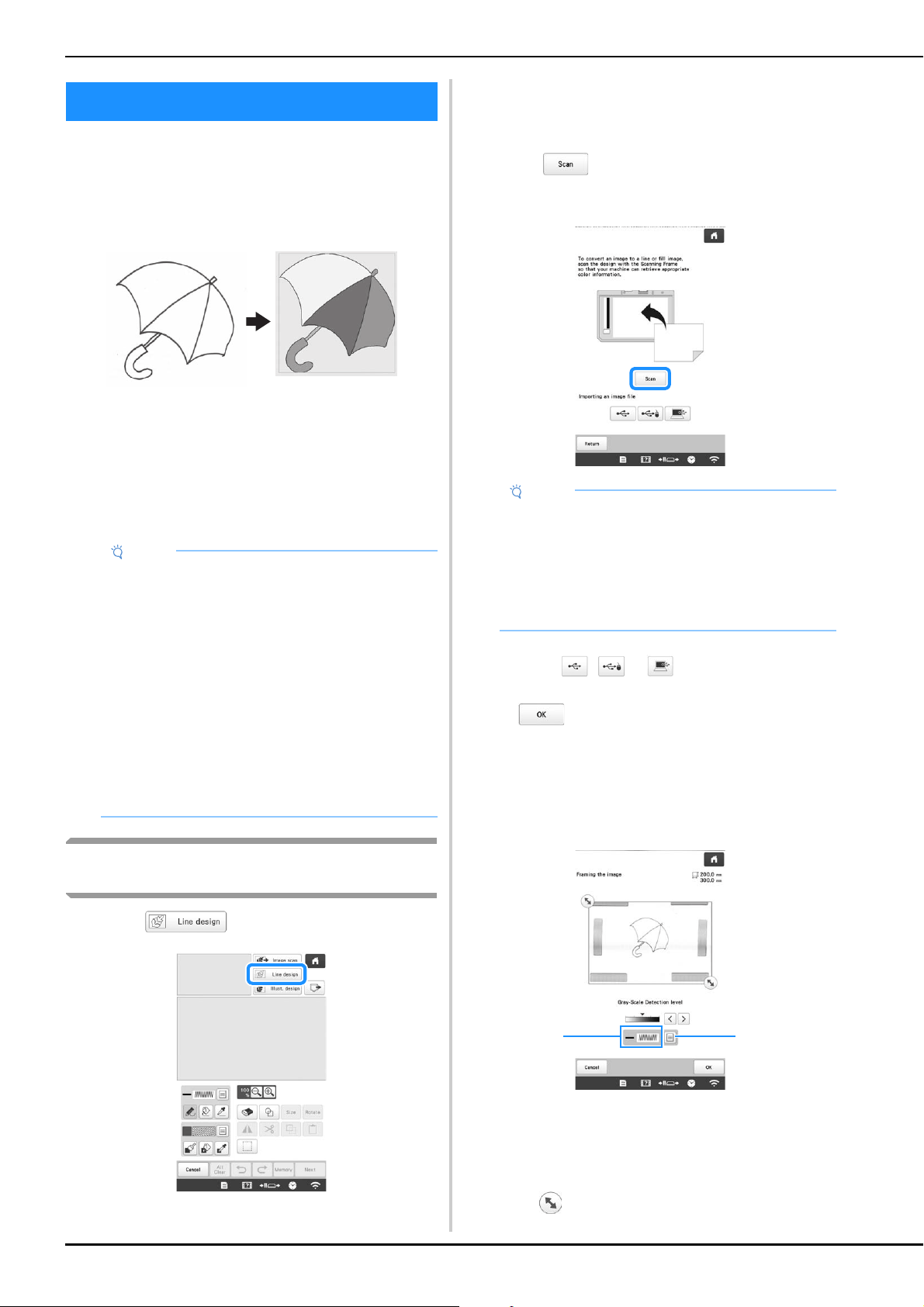
160
Custom patterns can be created from drawings. You can
create patterns by scanning your drawings using the
scanning frame* or importing an image from USB media or
computer.
* The scanning frame is an optional accessory in some
countries or regions.
Recommended line drawings for Line Scan
• Line drawings must be drawn clearly using lines with
approximately 1 mm (3/64 inch) thickness.
• Line drawings should be drawn in a strong contrast.
• If the lines are too short or gathered too densely, they
will not be scanned correctly.
Using the scanning frame to create a pattern
with Line Scan
a
Touch .
• When the background image has already imported,
continue with step
c.
• When the background image has not imported,
continue with step
b.
b
Touch .
* If you scan the image, make sure that the scanning
frame is attached to the machine. (page 156)
* To import an image from USB media or computer,
touch , or . (page 159)
When the message to start scanning appears, touch
.
Scanning starts.
c
When scanning is finished, specify the [Gray-Scale
Detection level] on the screen if necessary.
The [Gray-Scale Detection level] can change the black
and white threshold for the image.
1 Shows the stitch type and color of line.
2 Choices for stitch type and color of line.
* If you do not know how the settings should be
changed, first continue the operation without
specifying settings and check the results.
d
Move to frame the image for the pattern.
LINE SCAN
Note
• For details on creating patterns using color
illustrations, refer to “ILLUSTRATION SCAN” on
page 162.
• If you cannot scan the drawings as expected, you
can edit the design in My Design Center. Refer to
“PATTERN DRAWING SCREEN” on page 147.
• Line drawings are scanned without recognizing the
thickness of lines. If you want to change the
thickness of lines, specify in the settings screen.
Refer to “STITCH SETTINGS SCREEN” on
page 154.
• Line drawings are scanned as black lines. If you
want to change the colors, specify in My Design
Center. Refer to “Drawing lines” on page 149.
Note
• When scanning starts, some of the machine lights
will turn off in certain circumstances, in order to
increase the scan quality. The machine lights will
return to their original brightness when scanning
ends.
• You can import an image of 2 MB or smaller from
USB media or computer.
1 2
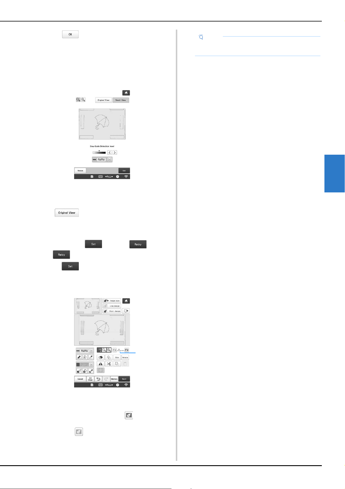
MY DESIGN CENTER
161
4
e
Touch .
The screen for confirming the converted image
appears.
f
In the screen for confirming the converted image, you
can adjust the [Gray-Scale Detection level], the line
color and stitch type again, if necessary.
* If you do not know how the settings should be
changed, first continue the operation without
specifying settings and check the results.
* To display the image before being converted, touch
. Compare the images before and after
being converted, and then change the settings if
necessary.
After changes to the settings described above have
been applied, changes to . Touch
to check that the image is as desired.
g
Touch .
The pattern drawing screen appears.
h
If necessary, edit the scanned image.
* After the scanned image is converted to stitching, it
appears as a background in the pattern drawing
screen. Use gauge 1 to adjust the transparency of
the background. Each touch of lightens the
background, making the line pattern darker. Each
touch of darkens the background, making the
line pattern lighter.
1
Note
• During scanning, the small dots that appear and
unnecessary lines can be erased.
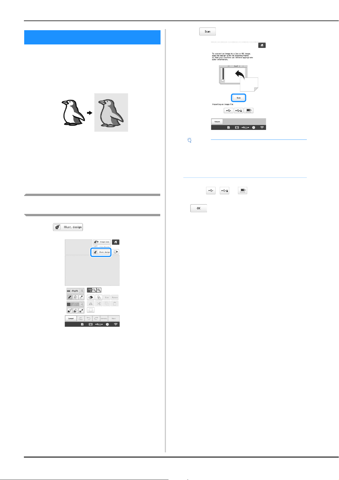
162
Custom patterns can be created from color illustrations.
You can create patterns by scanning an illustration using
the included scanning frame* or importing an image from
USB media or computer.
* The scanning frame is an optional accessory in some
countries or regions.
Recommended illustrations for Illustration Scan
• Illustrations that are clearly drawn, with no
gradation, fading or blurriness.
• Illustrations that are at least a 5 mm (13/64 inch)
square
• Illustrations that are extremely simple images
Using the scanning frame to create a pattern
with Illustration Scan
a
Touch .
• When the background image has already imported,
continue with step
c.
• When the background image has not imported,
continue with step
b.
b
Touch .
* To import an image from USB media or computer,
touch , or . (page 159)
When the message to start scanning appears, touch
.
Scanning starts.
ILLUSTRATION SCAN
Note
• When scanning starts, some of the machine lights
will turn off in certain circumstances, in order to
increase the scan quality. The machine lights will
return to their original brightness when scanning
ends.

MY DESIGN CENTER
163
4
c
When scanning is finished, specify the necessary
settings in the scan image confirmation screen.
Change the settings to adjust the image so it can easily
be converted to the desired pattern.
d
Move to frame the image for the pattern.
e
Touch .
The screen for confirming the converted image
appears.
f
In the screen for confirming the converted image,
adjust the image as necessary as in step
c.
* To display the image before being converted, touch
. Compare the images before and after
being converted, and then change the settings if
necessary.
After changes to the settings described above have
been applied, changes to . Touch
to check that the image is as desired.
g
Touch .
The pattern drawing screen appears.
h
If necessary, edit the scanned image.
* After the scanned image is converted to stitching, it
appears as a background in the pattern drawing
screen. Use gauge 1 to adjust the transparency of
the background. Each touch of lightens the
background, making the illustration pattern darker.
Each touch of darkens the background, making
the illustration pattern lighter.
1 [Max. Number of
Colors]
The number of colors in an image will
be reduced less than the number
specified here, and then the outline
will be extracted.
2 [Remove Background] Select whether or not the
background color will be included as
one of the colors.
3 [Line] Select whether or not the outline will
be detected as a line. A thick outline
can also be detected as a region.
When detected as a line, the line
thickness and color can be specified.
Memo
• Touch to detect the outline.
Line thickness can be specified from 1.0 mm (1/16
inch) to 5.0 mm (3/16 inch).
• Touch to select the outline color. Select by
touching the color, or moving icon using
in the color selection screen.
3
2
1
Note
• During scanning, the small dots that appear and
unnecessary lines can be erased.
1
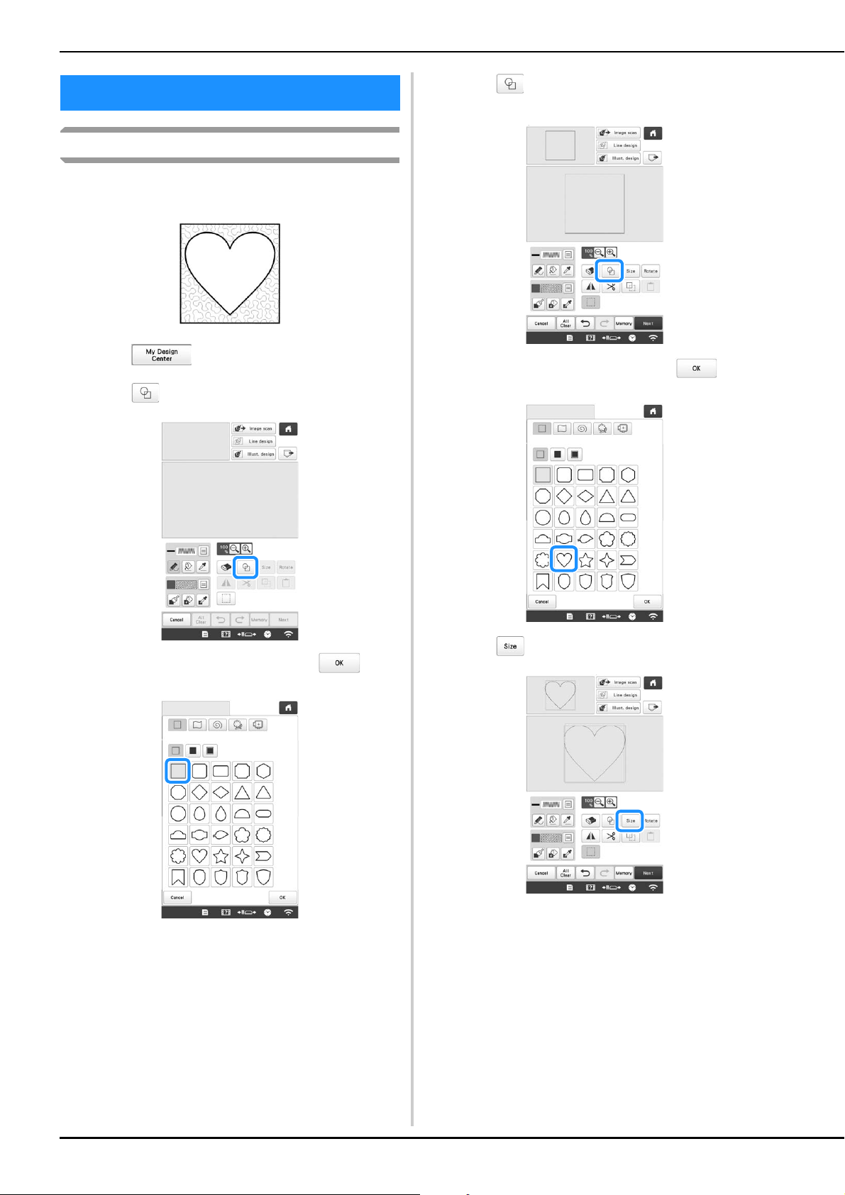
164
Basic stippling with My Design Center
Create a stippling design with the basic procedure.
Example:
a
Touch .
b
Touch .
c
Select the square shape, and then touch .
d
Touch .
e
Select the heart shape, and then touch .
f
Touch .
STIPPLING
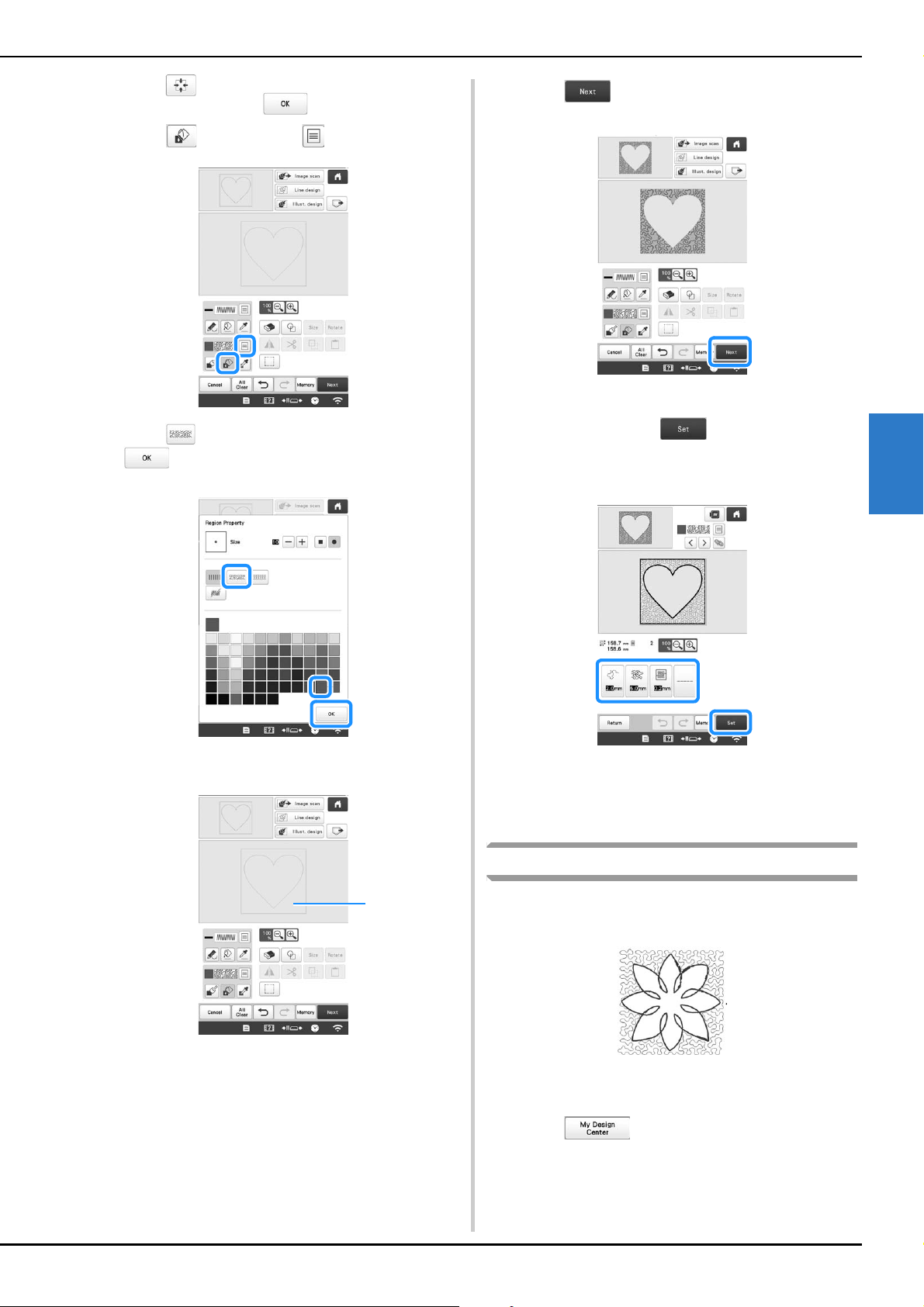
MY DESIGN CENTER
165
4
g
Touch until the heart shape fits in the square
shape, and then touch .
h
Touch , and then touch .
i
Touch , and then select the stitch color. Touch
after setting the color.
j
Select the area you want to set stippling effect.
1 Select this area.
k
Touch .
l
Adjust the stippling stitch settings to create the desired
effect, and then touch .
* For details, refer to “Specifying individual stitch
settings” on page 154.
m
Follow the procedure described on “EDITING THE
EMBROIDERY PATTERN” on page 44 to edit the
pattern as desired.
Scanning drawing to create stippling pattern
Create a custom pattern with stippling design.
Example:
a
Place a drawing of your design on the scanning frame.
b
Touch .
1
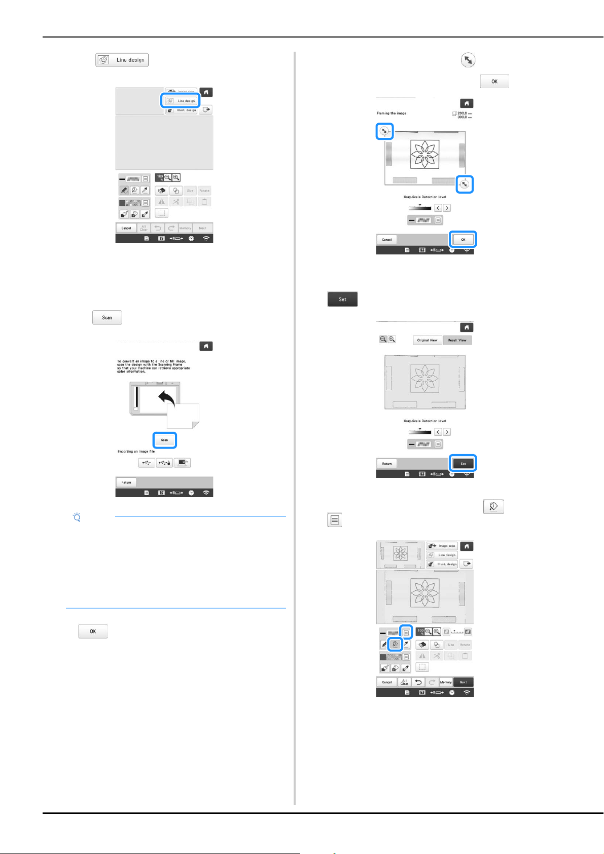
166
c
Touch .
• When the background image has already imported,
continue with step
e.
• When the background image has not imported,
continue with step
d.
d
Position the scanning frame on the machine, and then
touch .
When the message to start scanning appears, touch
.
Scanning starts.
e
When scanning is finished, move to frame the
image for the pattern, and then touch .
f
The screen for confirming the converted image
appears, adjust the image if necessary and then touch
.
The pattern drawing screen is displayed.
g
To set the outline of the pattern, touch , and then
.
Note
• When scanning starts, some of the machine lights
will turn off in certain circumstances, in order to
increase the scan quality. The machine lights will
return to their original brightness when scanning
ends.
• You can import an image of 2 MB or smaller from
USB media or computer.
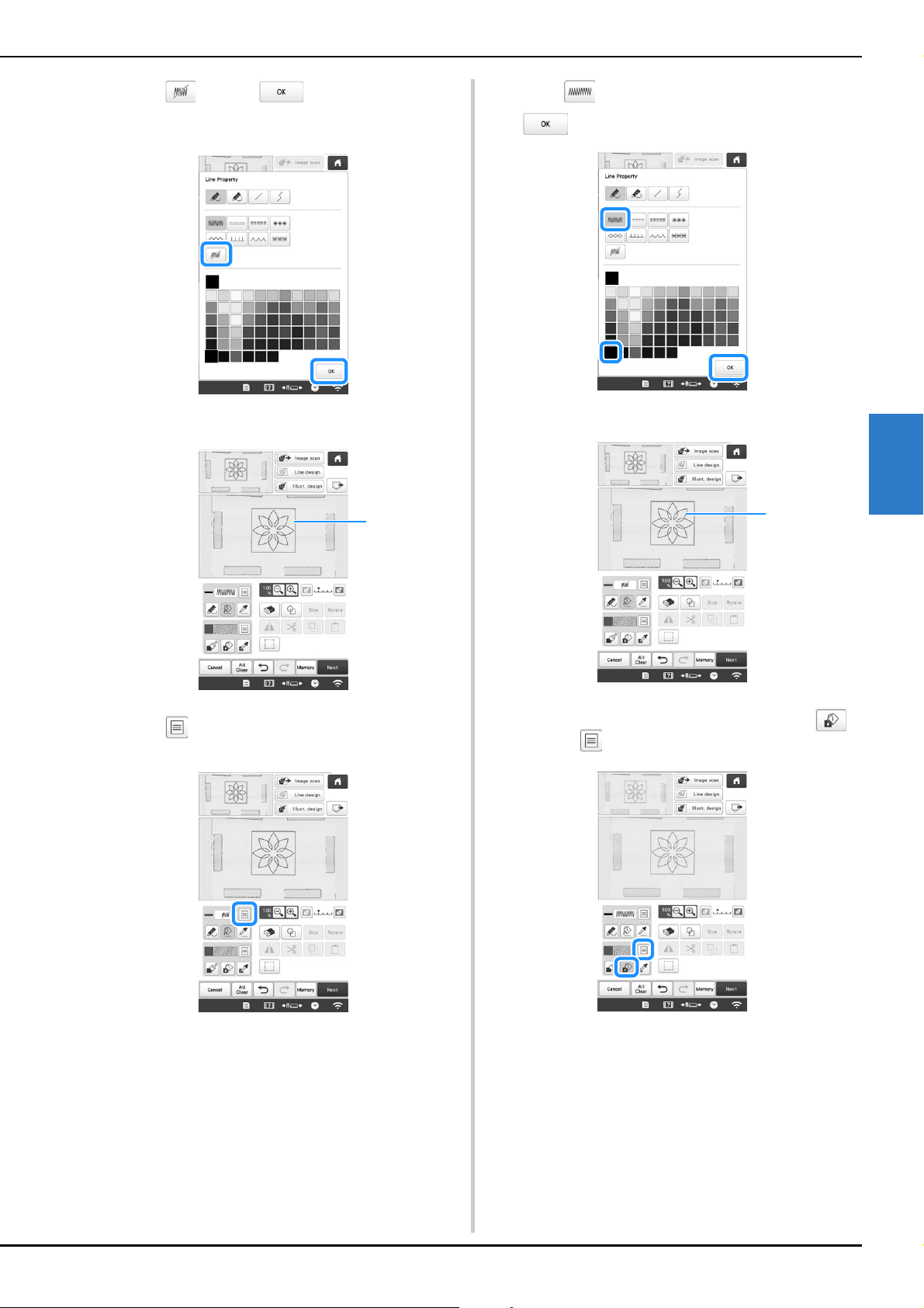
MY DESIGN CENTER
167
4
h
Touch and then .
This will set the outline without a stitch.
i
Select the outline of the pattern.
1 Outline of the pattern
j
Touch to select the color of the stitch around the
stippling effect.
k
Touch and select the stitch color, and then touch
.
l
Select the stitch line around the stippling effect.
1 Stitch line
m
To set the stitch color and fill stitch type, touch ,
and then .
1
1
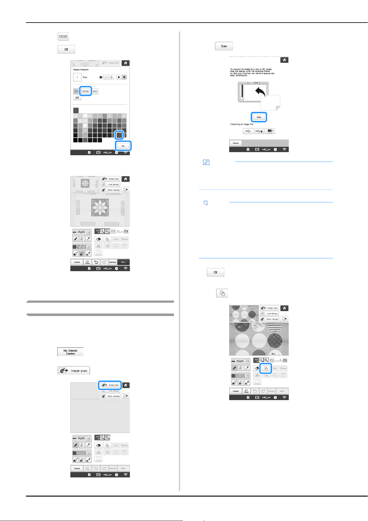
168
n
Touch , and then select the stitch color.
Touch after setting the color.
o
Select the area you want to set stippling effect.
p
Follow the procedure from step k on page 165 of
“Basic stippling with My Design Center”.
Scanning fabric and stippling
Use the fabric pattern to coordinate with the stippling pattern.
a
Hoop the fabric in the embroidery frame.
b
Touch .
c
Touch .
The image display screen appears.
d
Attach the embroidery frame on the machine, and then
touch .
When the message to start scanning appears, touch
.
Scanning starts.
e
Touch .
Memo
• Although the instructions in the LCD screen refer to
the scanning frame, this example uses an
embroidery frame for scanning.
Note
• When scanning starts, some of the machine lights
will turn off in certain circumstances, in order to
increase the scan quality. The machine lights will
return to their original brightness when scanning
ends.
• You can import an image of 2 MB or smaller from
USB media or computer.
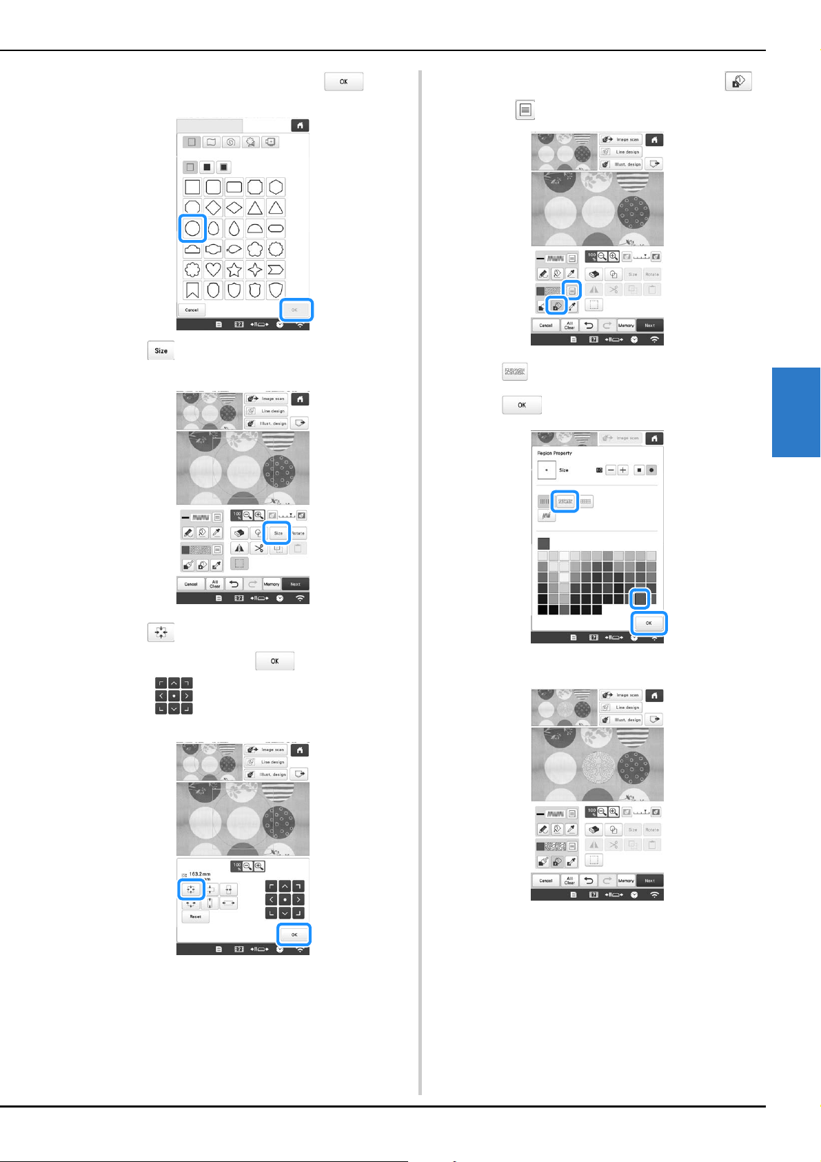
MY DESIGN CENTER
169
4
f
Select the circle shape, and then touch .
g
Touch to increase or decrease the size of the
circle.
h
Touch until the size of circle fits the pattern on
the fabric, and then touch .
* Use to align the position of the circle to the
pattern on the fabric.
i
To set the stitch color and fill stitch type, touch ,
and then .
j
Touch , and then select the stitch color.
Touch after setting the color.
k
Select the area you want to set stippling effect.
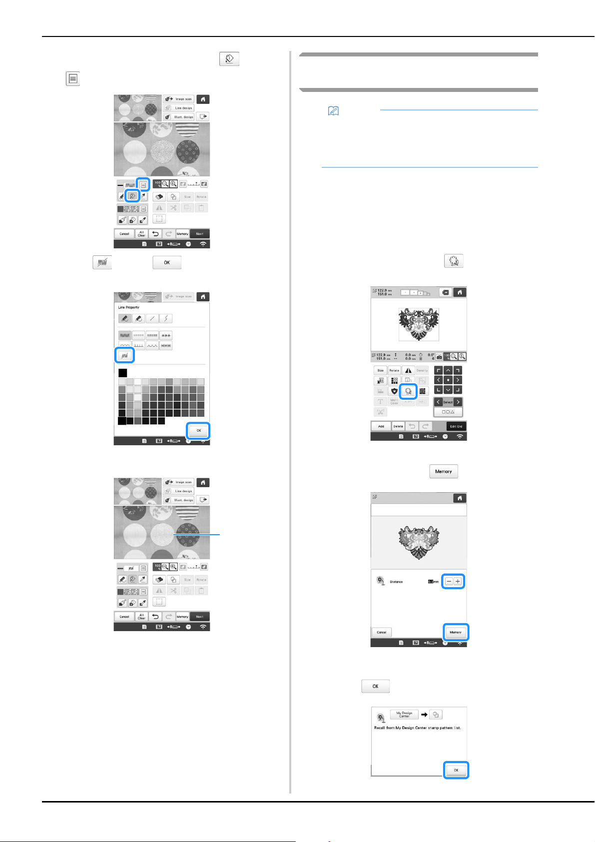
170
l
To set the outline of the pattern, touch , and then
.
m
Touch and then . This will set the outline
without a stitch.
n
Select the outline of the pattern.
1 Outline of the pattern
o
Follow the procedure from step k on page 165 of
“Basic stippling with My Design Center”.
Start embroidering on the fabric that you scanned at
first.
Decorative stitching around a pattern in
embroidery (a quilting function)
A quilt can be created with stippling around an embroidery
pattern.
a
Hoop the embroidery frame with batting sandwiched
between two layers of fabric, and then attach the
frame to the machine.
b
Select the pattern that decorative stitching will be
added around, and then touch in the edit screen.
The outline of the pattern is displayed.
c
Set the distance and touch .
A message appears, and the pattern outline is
registered as a stamp shape in My Design Center.
Touch .
1
Memo
• For best results, reduce the embroidery speed.
• For best results, hoop the stabilizer and fabric and
embroidery the design prior to adding the batting
and backing under the hoop for quilting.
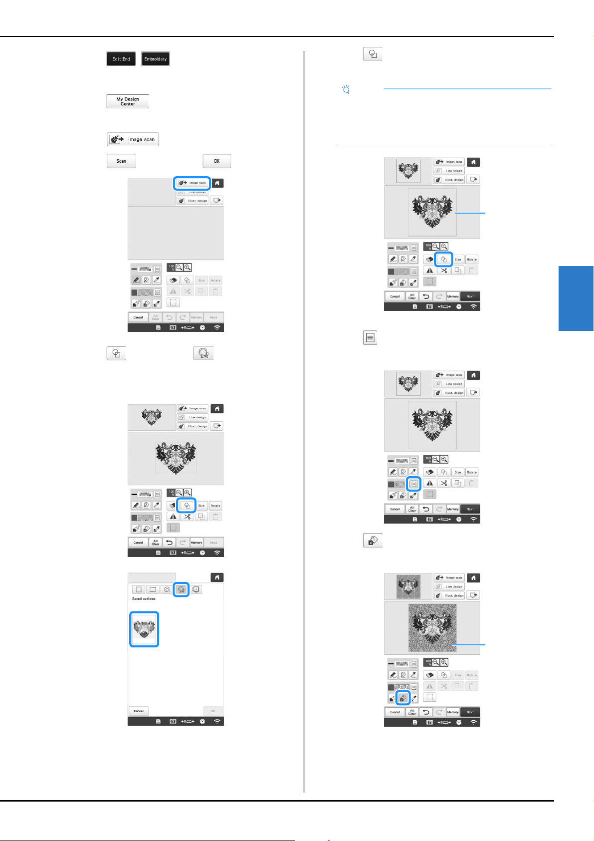
MY DESIGN CENTER
171
4
d
Touch , to continue to the embroidery
screen, and then embroider the pattern.
e
Touch in the pattern type selection screen
to start My Design Center.
f
Touch to scan the embroidered fabric.
Touch , and then touch .
g
Touch , and then touch to recall the stamp
shape registered in step
c, and then arrange it over
the scanned pattern.
h
Touch to use a stamp or rectangular frame to
determine the area to be stitched.
1 Stamp or rectangular frame
i
Touch for the brush tool keys to select the pattern
and color of the decorative stitching.
j
Touch , and then fill the area to be stitched
outside of the stamp shape outline.
1 Fill the area.
Note
• If the area is to be drawn by hand, be sure to draw
a completely closed shape. If the area is not
closed, it cannot be correctly filled with the
decorating.
1
1
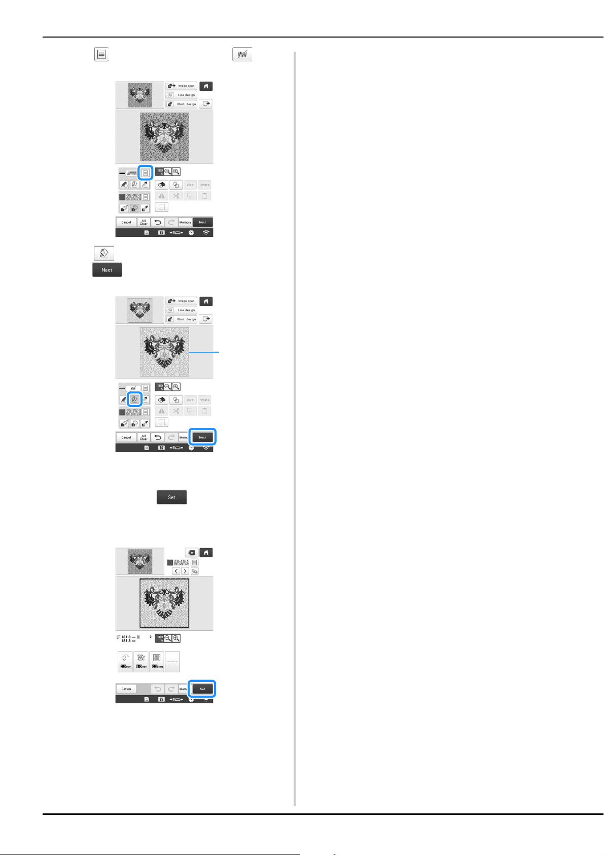
172
k
Touch for the line tool keys to select .
l
Touch , then select the frame outline, and then
touch .
1 Frame outline
m
Adjust the stippling stitch settings to create the desired
effect, and then touch .
* For details, refer to “Specifying individual stitch
settings” on page 154.
n
Follow the procedure described on “EDITING THE
EMBROIDERY PATTERN” on page 44 to edit the
pattern as desired.
o
Embroider the stippling stitch around the embroidery
pattern.
1
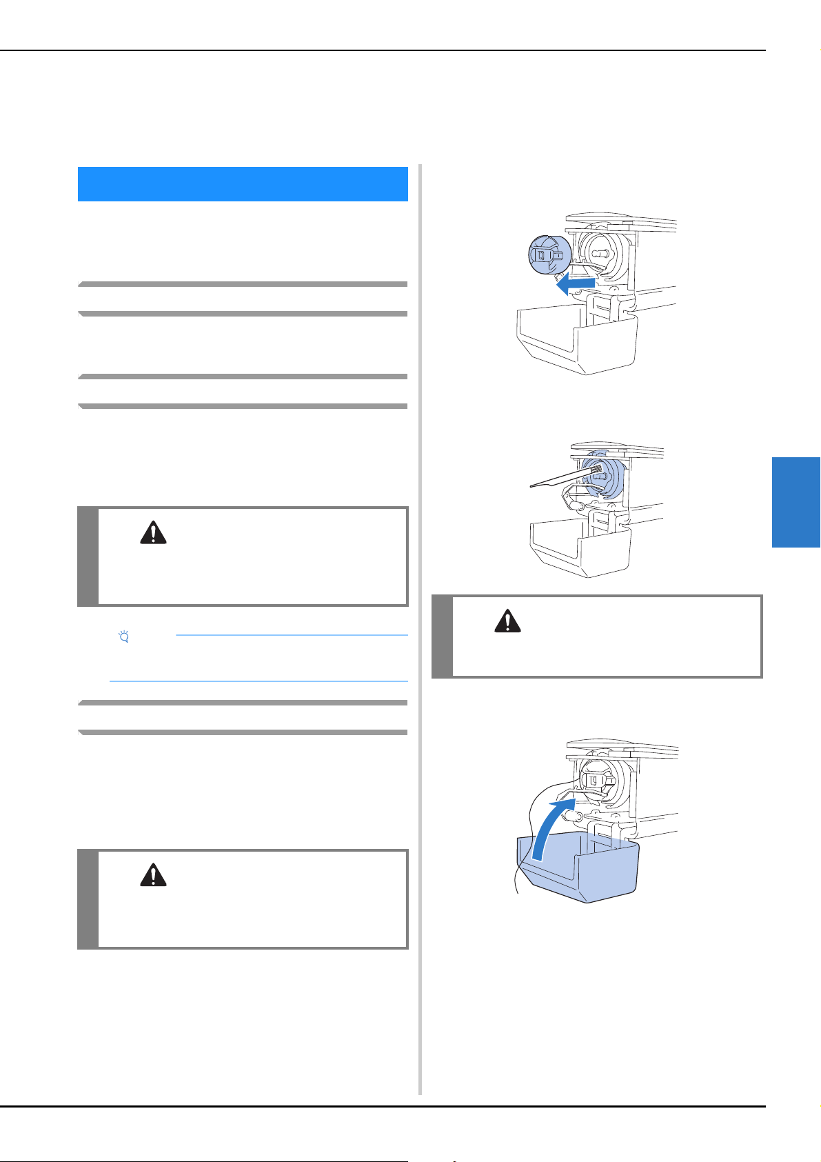
APPENDIX
173
5
Simple machine maintenance operations are described
below. Always keep the machine clean, otherwise
malfunctions may occur.
Cleaning the LCD
If the surface of the LCD is dirty, lightly wipe it with a soft dry
cloth. Do not use organic cleansers or detergents.
Cleaning the machine surface
If the surface of the machine is slightly dirty, wipe it with a soft
dry cloth. If the machine is heavily dirty, lightly soak a cloth in
neutral detergent, squeeze it out firmly, and then wipe the
surface of the machine. After cleaning it once with a wet
cloth, wipe it again with a dry cloth.
Cleaning the hook
Periodically remove lint and dust for better performance from
Hook race area.
Use the included cleaning brush.
a
Set the main power switch to “O” to turn off the
machine.
b
Open the hook cover, and remove the bobbin case.
(page 33)
c
Use the included cleaning brush to remove any lint and
dust from the hook and its surrounding area.
d
After cleaning is finished, insert the bobbin case into
the hook, and then close the hook cover. (page 35)
Chapter 5
APPENDIX
MAINTENANCE
CAUTION
• Unplug the power supply cord before cleaning
the machine, otherwise injuries or an electric
shock may occur.
Note
• Do not use chemical products, such as benzene or
thinner.
CAUTION
• Unplug the power supply cord before cleaning
the machine, otherwise injuries or an electric
shock may occur.
CAUTION
• If the hook is scratched or damaged, consult
your authorized Brother dealer.
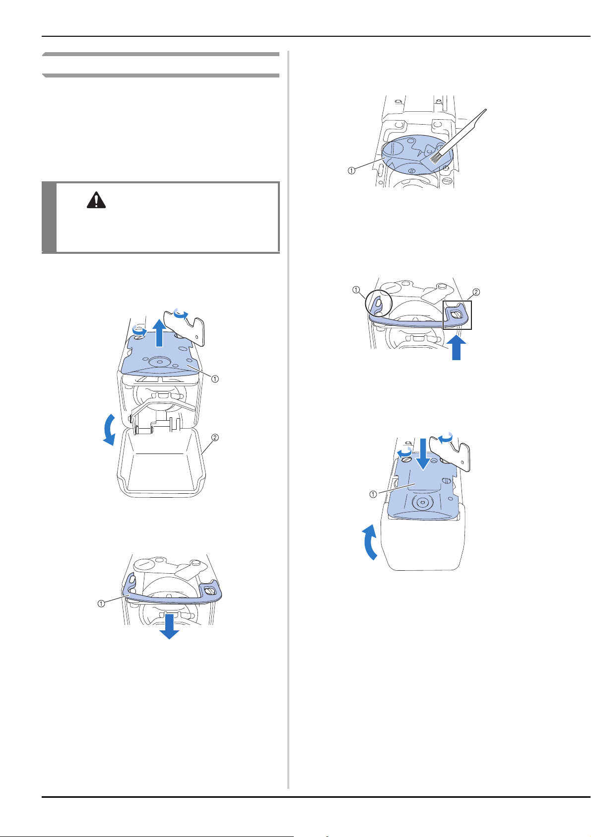
174
Cleaning around the needle plate
If lint and dust collect around the moving knife, the fixed knife
or the thread retaining plate, the thread may not be cut
correctly and various parts of the machine may be damaged.
Make sure to clean around the needle plate once a month.
Use the included 3 way screwdriver and cleaning brush.
a
Set the main power switch to “O” to turn off the
machine.
b
Remove the needle plate.
With the 3 way screwdriver, loosen the screws, remove
the needle plate, and then open the hook cover.
1 Needle plate
2 Hook cover
c
Remove the spacer.
1 Spacer
d
Use the included cleaning brush to remove any lint and
dust from the moving knife, the fixed knife, the thread
retaining plate, and their surrounding areas.
1 Remove all lint in this area
e
After cleaning is finished, install the spacer back.
First, position the spacer so that it hooks around the
elliptical notch, then position the spacer so that it
surrounds the screw head. Slide the spacer in the
direction of the arrow to secure it.
1 Elliptical notch
2 Screw head
f
Attach the needle plate in the opposite way that it was
removed in step b, and then close the hook cover.
1 Needle plate
CAUTION
• Unplug the power supply cord before cleaning
the machine, otherwise injuries or an electric
shock may occur.
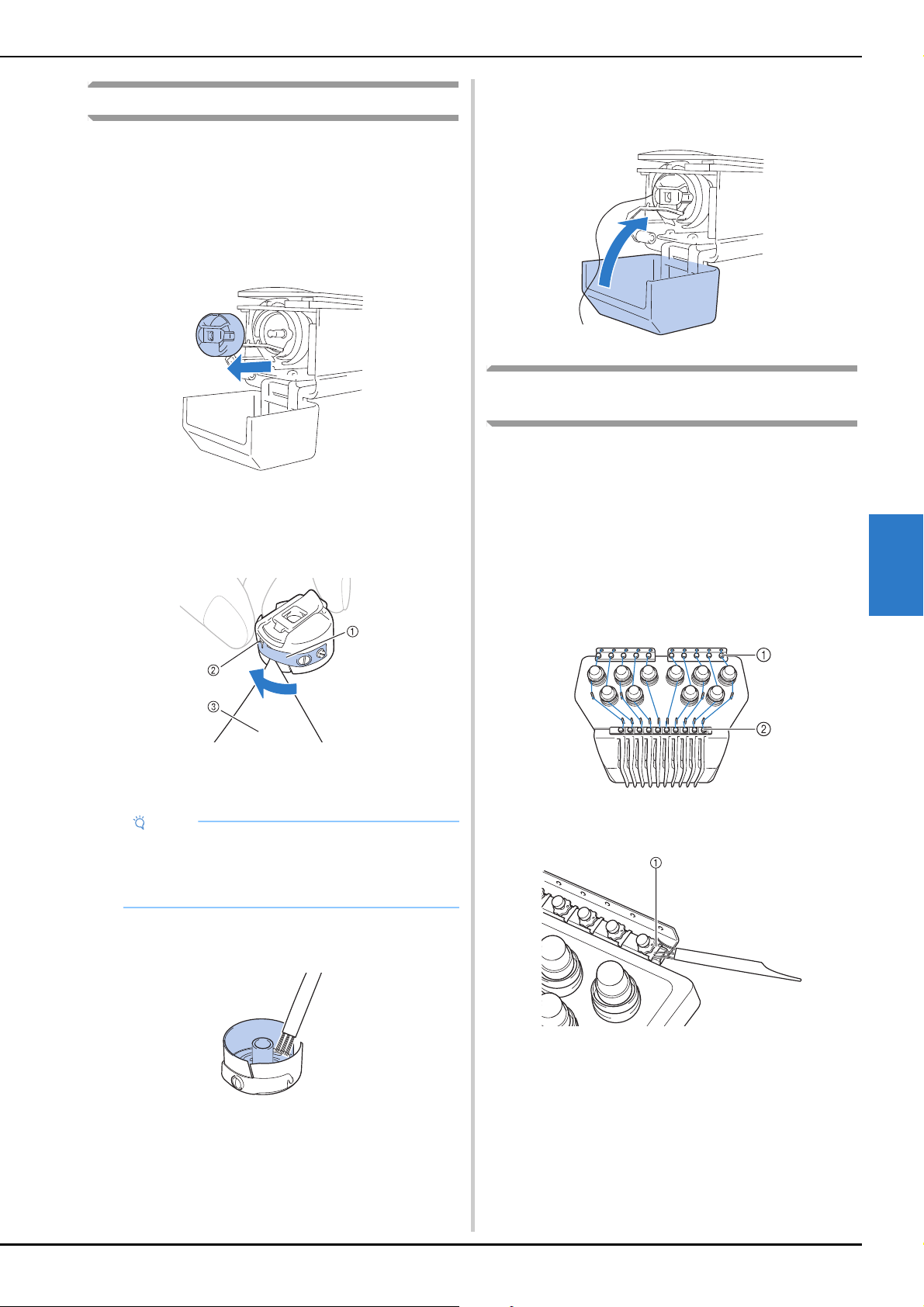
APPENDIX
175
5
Cleaning the bobbin case
Thread wax and dust easily collect around the hole in the
tension-adjusting spring on the bobbin case, resulting in an
incorrect thread tension. Therefore, it should be cleaned each
time when the bobbin is changed.
Use a piece of paper with the thickness of a business card.
a
Open the hook cover, remove the bobbin case, and
then remove the bobbin. (page 33)
b
Slide the paper under the tension-adjusting spring to
remove any dust.
Use a corner of the paper to remove any dust from
around the hole.
1 Tension-adjusting spring
2 Hole
3 Paper
c
Use the included cleaning brush to remove any lint and
dust from inside the bobbin case.
d
After cleaning is finished, insert the bobbin into the
bobbin case and the bobbin case into the hook, and
then close the hook cover. (page 34)
Cleaning the thread paths of the upper
threads
If dust or lint has accumulated in the thread guides or tension
unit in the paths of the upper threads, the thread may break
while embroidery is being performed. Periodically clean the
thread paths.
■ Cleaning the thread guides
a
Use the included cleaning brush to remove any lint and
dust from below the thread guide plates.
Clean the thread guide plates for both the upper thread
guides and the middle thread guides.
1 Upper thread guide
2 Middle thread guide
1 Thread guide plate
Note
• Do not bend the tension-adjusting spring. In
addition, do not use anything other than thick
paper or paper of the specified thickness to clean
the bobbin case.
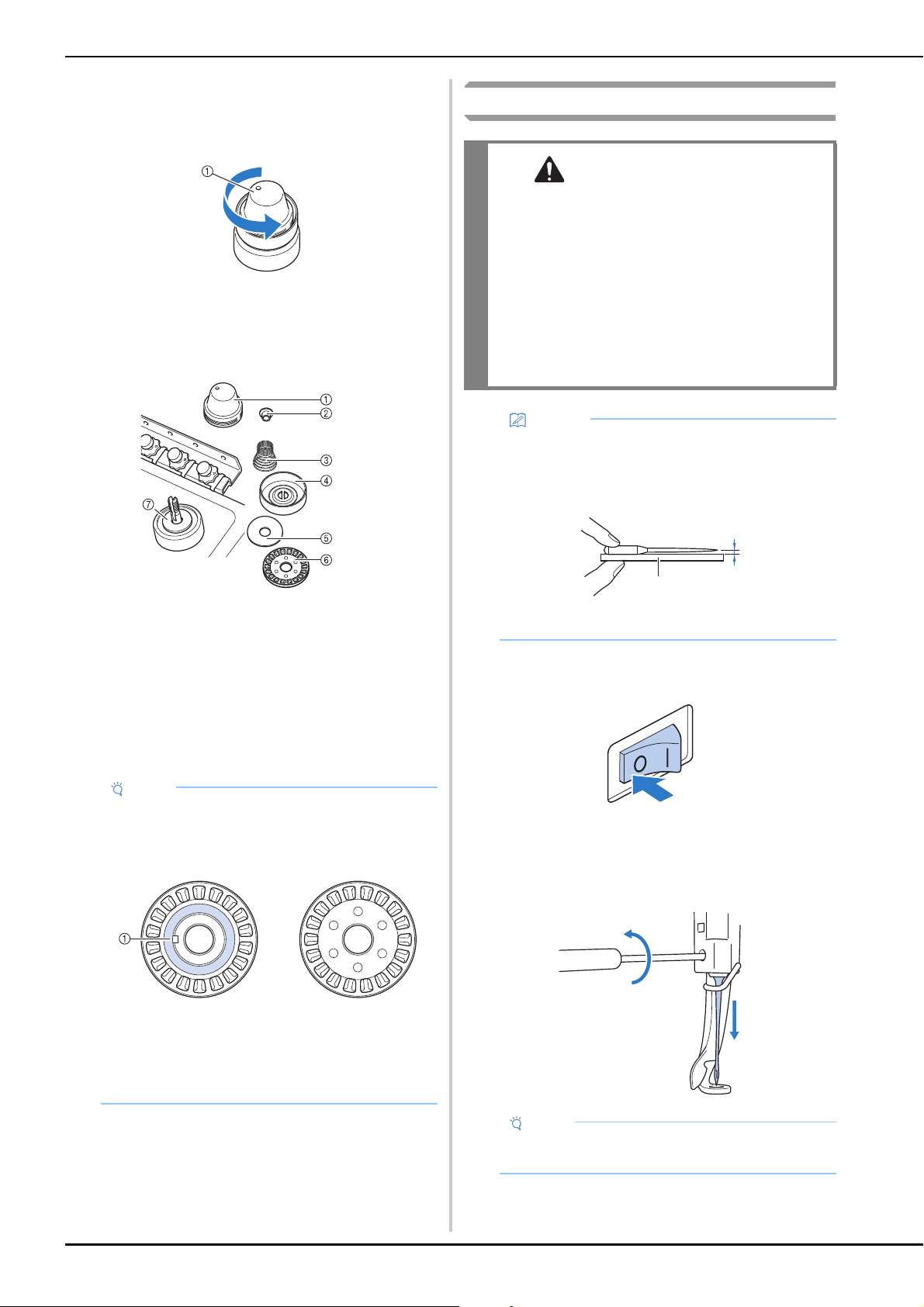
176
■ Disassembling and cleaning the tension unit
a
To remove tension dial, turn dial counterclockwise as
shown on illustration.
1 Tension dial
b
Using the included cleaning brush, remove any lint and
dust from the two pieces of felt washers (top, bottom)
inside the tension dial.
1 Tension dial
2 Nylon shoulder washer
3 Tension spring
4 Tension base spring
5 Felt washer (top)
6 Tension disc
7 Felt washer (bottom)
c
Reassembling the tension unit.
Replacing the needle
a
Set the main power switch to “O” to turn off the
machine.
b
Loosen the needle set screw and remove the needle.
Hold the needle with your left hand, and then hold the
Allen screwdriver in your right hand and turn the needle
set screw counterclockwise.
Note
• When reassembling the tension unit, be sure not to
install the tension disc upside-down.
There is a magnet on the bottom.
Bottom Top
1 Magnet
• When reassembling the tension unit, be careful not
to lose any parts or install any parts in an incorrect
order. The machine may not operate correctly if the
tension units are incorrectly reassembled.
CAUTION
• Be sure to turn off the machine before
replacing the needle, otherwise injuries may
result if the machine starts embroidering.
• Your machine is designed to use household
embroidery needles. The factory
recommended needle is “HAX 130 EBBR”
(Organ). Schmetz needles 130/705 H-E may
be used as a substitute.
• Never use bent needles. Bent needles can
easily break, possibly resulting in injuries.
Memo
• To check the needle correctly, place the flat side of
the needle on a flat surface. Check the needle from
the top and the sides. Throw away any bent
needles.
1 Parallel space
2 Flat surface (glass, etc.)
Note
• Be sure to use the included Allen screwdriver to
replace the needle.
a
b
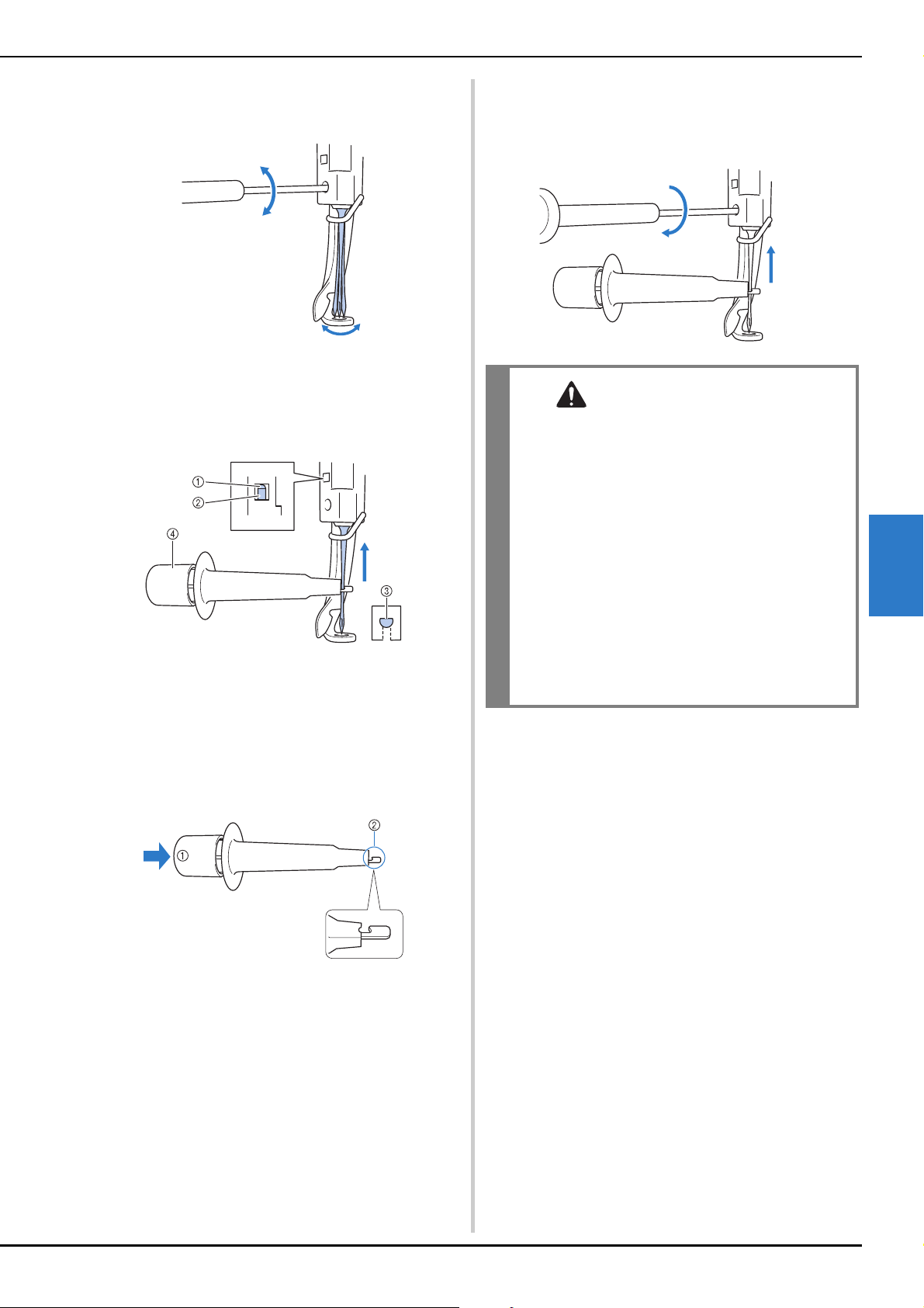
APPENDIX
177
5
• Do not apply extreme force when loosening or
tightening the needle set screw, otherwise the
machine may be damaged.
c
With the flat side of the needle toward the back of the
machine, insert the needle all the way up until it
touches the needle bar stopper.
Pass the needle through the hole in the presser foot, and
then use the needle changing tool to lift up the needle.
1 Needle bar stopper
2 Needle
3 Flat side of needle
4 Needle changing tool
Hold the needle changing tool and press the end of the
needle changing tool 1 in to extend the needle-
mounting clamp 2. Attach the clamp to the needle, and
then release the pressed area to clamp the needle. To
unclamp the needle, press 1 again.
1 End of the needle changing tool
2 Needle mounting clamp
d
While holding the needle in place with your left hand,
tighten the needle set screw.
Use the Allen screwdriver to turn the needle set screw
clockwise.
CAUTION
• Be sure to insert the needle in the needle bar
chamber until it reaches the needle bar
stopper and securely tighten the needle set
screw with the Allen screwdriver, otherwise
the needle may break or the machine may be
damaged.
• If the needle is not fully inserted, the hook of
the automatic needle-threading mechanism
will not pass through the eye of the needle
during automatic needle threading, and the
hook may bend or the needle cannot be
threaded.
• If the hook of the automatic needle-threading
mechanism is bent or damaged, contact your
authorized Brother dealer.
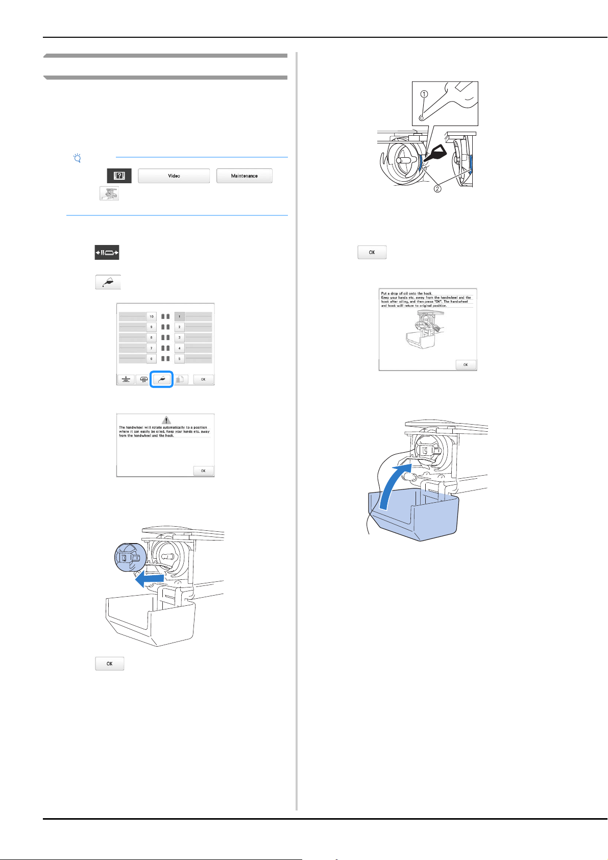
178
Oiling the machine
In order to extend the life of the machine’s parts and keep the
machine operating correctly, be sure to oil the machine
before the first time that it is used.
Afterward, put a drop of oil onto the hook once a day before
use.
■ Oiling the race
a
Touch .
b
Touch .
Following message appears.
c
Open the hook cover, and remove the bobbin case.
(page 33)
d
Touch .
The race moves to the correct position for oiling.
e
Put a drop of oil onto the hook.
1 Punch a small hole in oil bottle.
2 Apply oil here.
f
Touch appeared in the following screen.
The race returns to its original position.
g
After oiling, insert the bobbin case into the hook, and
then close the hook cover. (page 35)
Note
• Touch , , ,
then , in that order, to see a video of how to oil
the machine.
Front angle view Side view
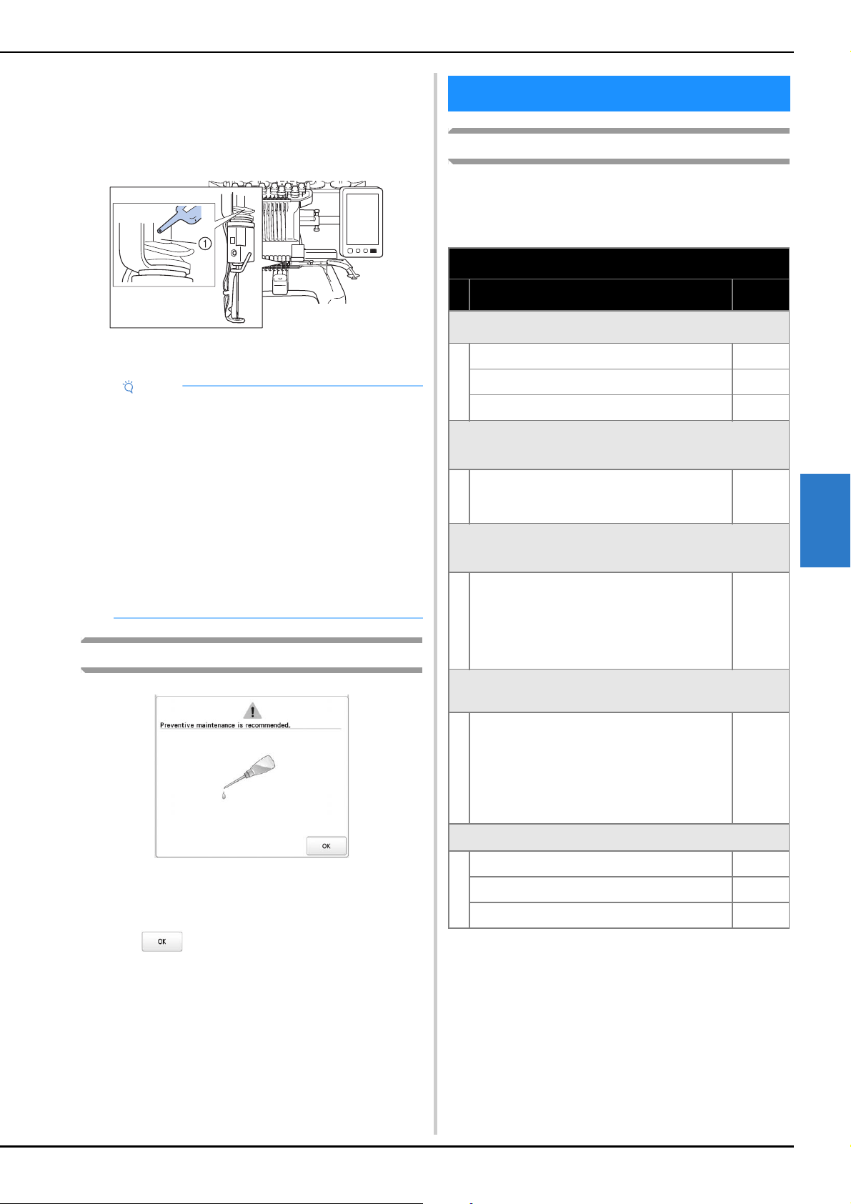
APPENDIX
179
5
■ Oiling the needle bars
From embroidering screen, select one needle bar at a
time. (page 86) Rotate the handwheel toward the LCD
panel bringing the needle bar to its lowest position. Put
one drop of oil, as high as possible on the needle bar
above the felt washer.
1 Apply oil here.
• Too much oil may drip onto embroidery project.
About the maintenance message
Once this message appears, it is recommended to take your
machine to your nearest authorized Brother dealer for a
regular maintenance check. Although this message will
disappear and the machine will continue to function once
you touch , the message will display several more
times until the appropriate maintenance is performed.
Please take the time to arrange for the maintenance that your
machine requires once this message appears. Such steps will
help to ensure you receive continued, uninterrupted hours of
machine operation for the future.
Troubleshooting
If the machine does not operate correctly, check for the
following points/issues before requesting service.
If the reference page is “*” or the suggested remedy does not
correct the problem, contact your authorized Brother dealer.
Note
• Put a drop of oil onto the hook once a day before
use.
• Apply one drop of oil on the lower needle bar
above the felt washer every 40 – 50 hours of
embroidering time.
• Apply only machine oil. Use of any other type of oil
may result in damage to the machine.
• Do not apply too much oil. Fabric or thread may get
contaminated. If too much oil is applied, wipe off
any excess with a rag.
• If the thread breaks while embroidering or the
operating noise of the hook becomes loud, apply
oil onto the race hook.
TROUBLESHOOTING
Symptom
Probable Cause/Remedy Page
The machine does not operate.
The machine is not turned on. 22
The machine has not been unlocked. 87
The “Start/Stop” button was not pressed. 87
The embroidery frame cannot be attached to the
machine.
The embroidery frame holder attached to the
machine is not appropriate for the selected
embroidery frame.
66
The embroidery frame cannot be removed or
attached.
Depending on the position where the machine’s
carriage has stopped, it may be difficult to
remove or attach the embroidery frame.
• Touch the Needle bar/Frame move key to
position the carriage, so the embroidery frame
can easily be removed or attached.
66
Embroidering is interrupted while embroidering a
large project.
Embroidering is interrupted by the presser feet
not in use catching on the fabric outside of the
design area.
• Stitch the design as close to the center of the
embroidery frame using needle bars 3 through
7, keeping the head of the machine as
centered as possible.
57, 58
The needle breaks.
The needle is not installed correctly. 176
The needle set screw is loose. 176
The needle is bent or blunt. 176
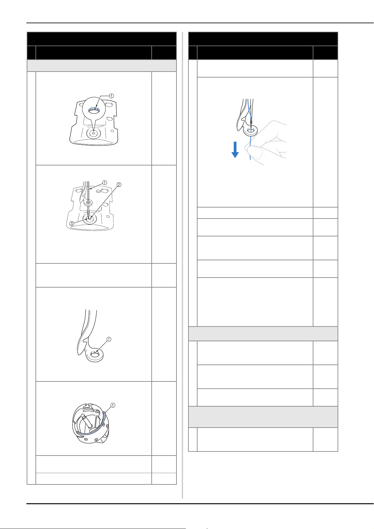
180
The needle breaks.
The area around the hole in the needle plate is
damaged.
1 Scratches/Burrs
• Replace the needle plate.
*
The needle hits/touches the needle plate.
1 Needle
2 Hole in needle plate
3 Needle hits hole
• Replace the needle.
176
*
The presser foot is set too high and not correctly
positioned.
The needle hits/touches the presser foot.
*
The area around the embroidery foot hole is
damaged.
1 Scratches or Burrs
• Replace the presser foot.
*
Sliding surface on hook race is not smooth. There
are scratches or burrs on it.
1 Hook race area
*
The bobbin or bobbin case are not correctly
installed.
33, 35
The hook is not correctly installed. *
Symptom
Probable Cause/Remedy Page
The hook stopper is not correctly installed, the
hook is making a complete rotation.
*
The upper thread is not threaded correctly.
The upper thread is catching somewhere.
• Pull the upper thread by hand from below the
presser foot, and check that the thread moves
smoothly. If the thread does not move, it is not
threaded correctly. Thread the upper thread
correctly. Make sure the thread is caught by
the needle bar thread guide.
82
The upper thread tension is set too high. 118
A bobbin designed specifically for this machine is
not used.
33
The needle and the hook are not correctly
passing each other.
• Hook timing may be OFF.
*
There is backlash play (forward/backward) in the
needle bar case.
*
The thread density of the embroidery data is too
fine.
Three or more overlapping stitches are being
embroidered.
• Using a data design system, correct the thread
density and overstitching settings in the
embroidery data.
190
The thread is not cut automatically.
Lint or dust has accumulated around the needle
plate (moving knife, fixed knife or thread retaining
plate).
174
A bobbin case designed specifically for this
machine is not used.
• Use the correct bobbin case.
—
Lint or dust has accumulated in the thread
tension disc.
176
After the threads are automatically cut, the upper
thread is too short and comes out of the needle.
Lint or dust has accumulated around the needle
plate (moving knife, fixed knife or thread retaining
plate).
174
Symptom
Probable Cause/Remedy Page
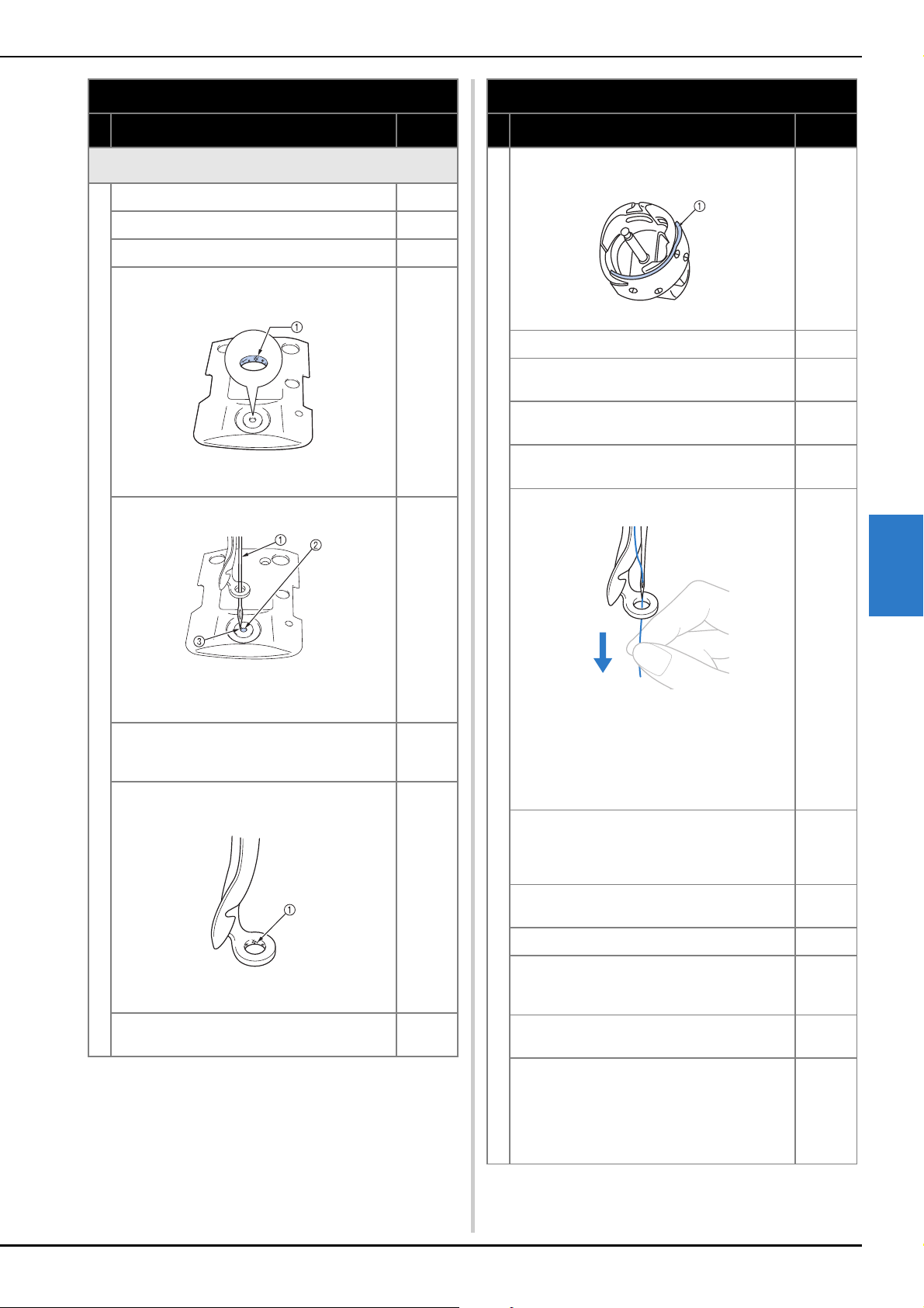
APPENDIX
181
5
The upper thread breaks.
The needle is not correctly installed. 176
The needle set screw is loose. 176
The needle is bent or blunt. 176
The area around the hole in the needle plate is
damaged.
1 Scratches/Burrs
• Replace the needle plate.
*
The needle is touching the needle plate.
1 Needle
2 Needle plate hole
3 Needle touching hole
*
The presser foot is set too high and not correctly
positioned.
The needle hits/touches the presser foot.
*
The area around the embroidery foot hole is
damaged.
1 Scratches/Burrs
• Replace the presser foot.
*
Using a specialty thread like a metallic thread.
• Slow down the machine embroidery speed.
89
Symptom
Probable Cause/Remedy Page
Sliding surface on hook is not smooth. There are
burns on it.
1 Hook race area
*
The thread is loose in the hook area. 173
The play between the hook and the race is too
much.
*
The hook does not rotate smoothly.
• Remove lint, clean and apply oil.
173, 178
The space between the hook stopper and the
hook cannot be adjusted.
*
The upper thread is not threaded correctly.
• Pull the upper thread by hand from below the
presser foot, and check that the thread moves
smoothly. If the thread does not move
smoothly, it is not correctly threaded. Un-
thread the machine and re-thread the machine.
Make sure the thread is correctly positioned in
the needle bar thread guide.
82
Upper thread is not positioned in upper or middle
thread guide.
• Make sure thread passes completely under
upper and middle thread guide.
82
There are knots or tangles in the thread.
• Remove any knots or tangles.
—
The upper thread tension is too high. 118
The bobbin thread tension is incorrect.
The thread does not roll out of the bobbin case
smoothly.
116
The bobbin case is damaged.
• Replace the bobbin case with a new one.
33
The bobbin thread is not wound correctly.
• Check that the bobbin is wound so that it is
about 80% full and that the thread is evenly
wound. If the bobbin is not correctly wound,
replace the bobbin with one that is correctly
wound or rewind the bobbin.
33
Symptom
Probable Cause/Remedy Page
182
The upper thread breaks.
A bobbin designed specifically for this machine is
not used.
33
The automatic needle-threading mechanism is
broken.
*
Adhesive is attached to the needle.
• Replace the needle.
176
The fabric is not taut. 61, 62
The thread quality is poor.
• The thread quality is too weak due to age of
thread. Replace thread.
—
The embroidery data contains stitches with a
pitch of zero.
124
The embroidery data contains many stitches with
an extremely small pitch.
124
The thread density of the embroidery data is too
fine.
Three or more overlapping stitches are being
embroidered.
• Using a data design system, correct the thread
density and overstitching settings in the
embroidery data.
190
Lint or dust has accumulated in the thread
tension disc.
176
The bobbin thread breaks.
The bobbin thread is not correctly threaded. 34
The bobbin is scratched or does not rotate
smoothly.
• Replace the bobbin.
33
The bobbin case is damaged.
• Replace the bobbin case.
33
The thread is tangled. 173
A bobbin designed specifically for this machine is
not used.
33
Lint or dust has accumulated in the thread
tension disc.
176
Stitches are skipped.
The upper thread is not threaded correctly. 82
The needle is bent or blunt. 176
The needle is not installed correctly. 176
Dust has accumulated under the needle plate or
in the hook.
173, 174
The needle and the hook are not correctly
passing each other.
*
The thread twist is either too tight or too loose.
• Improper twisting results in irregular loop
formation. Try using a new spool.
—
Symptom
Probable Cause/Remedy Page
The embroidery pattern is misaligned.
The thread is tangled.
• Use tweezers to remove any tangled thread
from the hook.
—
The fabric is not secured in the embroidery frame
(for example, the fabric is not taut).
61, 62
The embroidery frame is too large for the size of
the embroidery.
65
The thumb screws on the embroidery frame
holder are loose.
21
Appropriate stabilizer (backing) is not used. 60
The embroidery frame is not correctly attached to
the carriage.
• Correctly attach the embroidery frame to the
carriage. Make sure that the pins on the left
and right arms of the embroidery frame holder
securely fit into the holes in the handles on the
embroidery frame.
64
The carriage or the embroidery frame is hitting
objects.
• The pattern may become misaligned if the
carriage or embroidery frame is hitting objects.
—
The fabric is caught or pinched.
• Stop the machine, and then correctly position
the fabric.
—
The carriage moved while removing embroidery
frame.
• The pattern may become misaligned if the
presser foot was hit or the carriage was moved
while embroidery.
• Be careful when removing and reattaching the
embroidery frame while embroidery.
If the carriage is moved, turn the machine off,
then on again. The correct frame position at the
time that the machine was stopped is stored in
the machine’s memory, and the embroidery
frame is returned to the correct position.
—
The design was not digitized correctly.
• The design may need more pull compensation
or underlay to accommodate stretchy or high-
napped fabrics.
—
The size of the installed embroidery frame is not
correctly detected.
The thumb screws on the embroidery frame
holder are loose.
21
The starting position for the embroidery frame is
horizontally misaligned.
The thumb screws on the embroidery frame
holder are loose.
21
Symptom
Probable Cause/Remedy Page
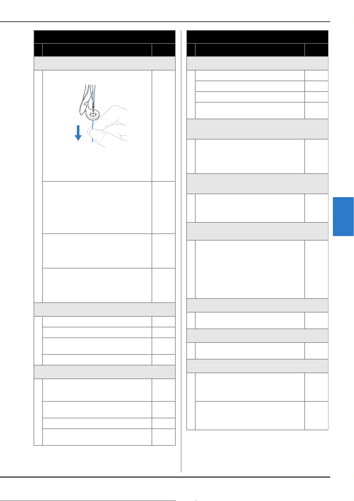
APPENDIX
183
5
There are loops in the upper thread.
The upper thread tension is low.
• After passing the upper thread through the hole
in the presser foot, pull the thread by hand to
check the thread tension. If it is difficult to
determine, compare it with other needle bars
where looping does not occur.
—
The thread tension does not correspond to the
amount that the thread tension knob was
tightened.
• If the thread tension cannot be adjusted,
thread wax and dust may have collected in the
upper or middle thread guide plates, causing
the thread tension guide plates to rise. Clean
the thread tension guide plates.
175
Thread is not correctly threaded around upper
thread tension discs.
• Clean upper thread tension disc. Rethread and
make sure tension disc rotates when pulling on
thread.
176
The thread quality is poor.
• Try embroidery with different thread. If the
problem no longer occurs after the thread is
changed, the thread quality is the problem.
Replace the thread with one of good quality.
—
The machine is noisy.
Lint may be wound in the hook. 173
The upper thread is not threaded correctly. 82
The hook is damaged.
• Replace the hook.
*
Not enough oil was applied. 178
The needle threader cannot be used.
The needle is not at the correct position.
• Touch the key to move the desired needle bar
to be threaded into embroidering position.
86
Recommended needles are not used on this
machine.
176
The needle is not installed correctly. 176
The hook on the automatic needle-threading
mechanism is bent.
*
Symptom
Probable Cause/Remedy Page
The thread tension is incorrect.
The upper thread is not threaded correctly. 82
The bobbin thread is not correctly threaded. 34
The bobbin thread tension is incorrect. 116
Lint or dust has accumulated in the thread
tension disc.
176
The upper thread comes out of the needle when
embroidering begins.
If a short length of thread remains after the thread
is trimmed, the needle may become unthreaded
when embroidering begins again.
• Set the remaining length of thread to [Long Tail]
on settings screen.
124
The upper thread does not reach the bobbin thread
when embroidering begins.
There is no more thread in the bobbin, the thread
does not feed from the bobbin, or the thread that
is fed from the bobbin is too short.
• Correctly thread the bobbin thread.
34
Although the thread is not broken, a broken thread
error occurs and the machine stops.
If the thread breakage sensor in the thread
tension disc of the thread tension knobs cannot
detect that the thread is being fed, even if the
machine is running, a broken thread error occurs
and the machine is stopped.
• Correctly pass the thread through the thread
tension disc. If the broken thread error occurs
after the machine is rethreaded, the sensor
may be damaged.
176
*
The thread is worn.
Lint or dust has accumulated in the thread
tension disc.
176
Jump stitches are long.
Lint or dust has accumulated in the thread
tension disc.
176
There are needle cuts or holes in the garment.
The needle is dull.
• Replace the needle. Dull needles have a
difficult time passing through the garment,
causing fabrics to tear.
176
The fabric is too delicate.
• The simple penetration of the needle could
damage delicate fabrics. Use stabilizer on top
of fabric.
—
Symptom
Probable Cause/Remedy Page
184
Fabric is puckering.
The thread tension is too tight.
• Adjust the tension according to the type of
fabric and thread being used. Polyester thread
will stretch during embroidery especially if the
tensions are set too high. After the stitching is
complete, the thread returns to its original
strength, causing puckers in the fabric.
118
The framing tension of the fabric is incorrect.
• Tightly frame non-stretchable, woven fabrics.
Loose framing will cause the fabric to bunch up
under the stitching. Tautly frame soft knits
using a stable backing. Overstretching the
garment will cause it to look puckered when
the frame is removed.
—
The column stitches are too long.
• Re-digitize the design with fill stitching or with
multiple rows of column stitching.
—
The needle is dull.
• Dull needles push fabric down and damage
material. Replace the needle.
176
The design density is too heavy.
• Too many stitches in an area pull fabric,
causing it to pucker. Slightly decrease the
design density by 5% to 10%.
124
The LCD cannot be read.
The LDC screen is too bright or too dark.
• Adjust the brightness of the screen display.
—
When embroidering thick fabric, the fabric cannot be
correctly hooped.
Fabric slips within the frame because of its
thickness.
• Wrap masking tape or bias tape around the
outer frame. The tape will provide resistance so
that the fabric does not easily slip.
—
There is flickering in built-in camera image displayed
in the LCD screen.
If the machine is being used in a very cold
environment, there may be flickering in the built-
in camera image displayed in the LCD screen.
• This is not a malfunction. Leave the machine
turned on, and then wait a while before using
the built-in camera.
—
The machine does not detect the embroidery
positioning sticker.
Sunlight or light from the outside comes into the
machine.
• Block light from the outside.
—
The scanned image is too bright or too pale.
Sunlight or light from the outside comes into the
machine.
• Block light from the outside.
—
Symptom
Probable Cause/Remedy Page
There is misalignment in the scanned image or
camera image.
The correct table installation setting has not been
selected.
• The machine software adjusts scanned images
and camera images according to the table
installation setting. Select the appropriate
setting.
73
The thickness of the fabric was not checked by
the machine.
• Before scanning fabric thicker than 2 mm
(approx. 5/64 inch) or before using the camera
to align patterns, activate [Fabric Thickness
Check].
74
CAUTION
• This machine is equipped with a thread
detecting mechanism. If the machine is not
threaded with the upper thread, the machine
will not operate correctly, even if the “Start/
Stop” button is pressed after unlocking the
machine.
• If the machine suddenly stops:
• Turn off the machine, and unplug the
power cord.
• Restart the machine with the correct
operating procedure. (page 22)
Symptom
Probable Cause/Remedy Page

APPENDIX
185
5
Error messages
If the “Start/Stop” button is pressed while the machine is not correctly set up or if an incorrect operation is performed, the
machine stops and informs you of the error with a buzzer and an error message. If an error message appears, correct the problem
according to the instructions in the message.
To close the message, touch or perform the correct operation, then touch . If the message appears again, consult
your nearest authorized Brother dealer.
Error messages Cause/solution
1 Can not find the positioning mark, please set the
frame to the previous position.
This message is displayed when the embroidery positioning sticker cannot
be found while embroidering a pattern for the optional jumbo frame. Perform
the operation again from step
h in “EMBROIDERY PATTERNS FOR THE
OPTIONAL JUMBO FRAME” on page 140.
2 Cannot change the configuration of the characters. This message is displayed when there are too many characters in the curved
text arrangement. Change the text arrangement or the embroidery frame.
3 Cannot communicate between PC and machine.
Please check the USB cable connections to run the
Link application.
This message is displayed when the machine cannot receive any data from
the computer in the Link mode with the USB cable connection. Turn off the
machine, and check the USB connection. After connect the USB cord
securely, turn on the machine again. (page 132)
4 Cannot connect to the PC. Please check the
network connection.
This message is displayed when the machine cannot receive any data from
the computer in the Link mode with the wireless LAN connection. Check the
wireless LAN connection between the computer and the machine, and then
turn off and on the machine. (page 132)
5 Cannot recognize the data for the selected pattern.
The data may be corrupted. Please turn off the
power and turn on again.
This message is displayed when trying to recall damaged pattern data or
data created using another manufacturer’s data design system. Turn the
machine off, then on again to return it to its normal condition.
6 Cannot recognize the embroidery positioning mark. This message is displayed when the machine fails to recognize the
embroidery positioning mark. Confirm that the embroidery positioning mark
is in the selected area. If problem persists, reposition the mark.
7 Can’t use this key during camera mode. This message is displayed when a key that cannot be used is touched after
was touched to enter camera mode. Touch to exit camera mode.
8 Change to a larger embroidery frame. This message is displayed when the thumb screws of the embroidery frame
holder are loose. Using the included 3 way screwdriver, firmly tighten the two
thumb screws. (page 64)
This message is displayed when the installed embroidery frame is too small.
Check which embroidery frames can be used, and then install a larger
embroidery frame. (page 62)
9 Check upper and bobbin thread. This message is displayed when the thread tension is too tight. Check the
tensions of the upper thread and bobbin thread, and then adjust them.
(page 116)
This message is displayed when the upper thread breaks or the thread
comes out of the thread tension disc or a thread guide. Check that the thread
passes under the upper and middle thread guides, and correctly thread the
upper thread. (page 82)
This message is displayed when lint or dust has accumulated in the thread
tension disc. Remove the tension dials, and then remove any lint or dust
accumulated between the felt washers. (page 176)
This message is displayed when the bobbin thread breaks or runs out.
Check that there is thread on the bobbin and that approximately 50 mm (2
inches) of thread has been pulled out, and then re-install the bobbin.
(page 33)
This message is displayed when there may be another cause. Refer to “The
upper thread breaks.” on page 181 or “The bobbin thread breaks.” on
page 182. Touch to advance or reverse through the stitching. (page 93)
10 Communication error. When this message is displayed, consult your nearest authorized Brother
dealer.
186
11 Communication time out error. When this message is displayed, consult your nearest authorized Brother
dealer.
12 Data receiving command error. When this message is displayed, consult your nearest authorized Brother
dealer.
13 EEPROM read/write error. When this message is displayed, consult your nearest authorized Brother
dealer.
14 Embroidering stop. When this message is displayed, consult your nearest authorized Brother
dealer.
15 Failed to save file. This message is displayed when you try to save more than 100 camera
image or settings screen image files in the USB media. In this case, delete a
file from the USB media or use different USB media.
16 Go to Embroidering Screen and press the unlock
key.
This message is displayed when the thread trimming button is pressed while
a screen other than the embroidering screen or embroidering settings screen
is displayed. Display either the embroidering screen or embroidering settings
screen.
17 Impossible to set the start & the end points. This message is displayed when embroidery cannot begin from the specified
starting position. Change the starting position or move the frame and change
the embroidering position. (page 126)
18 Inappropriate needle stop position This message is displayed when the needle has stopped at an incorrect
position. Turn the handwheel so that the mark on the handwheel is at the top,
and then touch .
19 Includes a special pattern that cannot be saved to
external memory. Save the pattern in the machine’s
memory.
This message is displayed when you try to save a copyright protected
pattern to USB media or computer.
According to copyright laws, patterns that are illegal to reproduce or edit
cannot be saved to USB media or computer. If this message is displayed,
save the pattern in the machine’s memory.
20 Machine PCB power off. When this message is displayed, consult your nearest authorized Brother
dealer.
21 Machine PCB reset. When this message is displayed, consult your nearest authorized Brother
dealer.
22 Main motor current error. When this message is displayed, consult your nearest authorized Brother
dealer.
23 Main motor encoder connect error. When this message is displayed, consult your nearest authorized Brother
dealer.
24 Main motor encoder signal error. When this message is displayed, consult your nearest authorized Brother
dealer.
25 Main motor rotate error. When this message is displayed, consult your nearest authorized Brother
dealer.
26 Main motor speed error. When this message is displayed, consult your nearest authorized Brother
dealer.
27 Needle bar case home position error. This message is displayed when the needle bar case cannot be moved to its
initial position. Touch to automatically reset the needle bar case.
28 Needle bar case position error This message is displayed when the needle bar case has stopped at an
incorrect position. Touch to automatically reset the needle bar case.
29 Needle case motor has been locked. This message is displayed when the needle bar case motor has locked up.
Touch to automatically reset the needle bar case.
30 Needle threader error This message is displayed when the automatic needle-threading mechanism
does not operate correctly. Remove the thread entangled in the automatic
needle-threading mechanism, and then touch .
Error messages Cause/solution
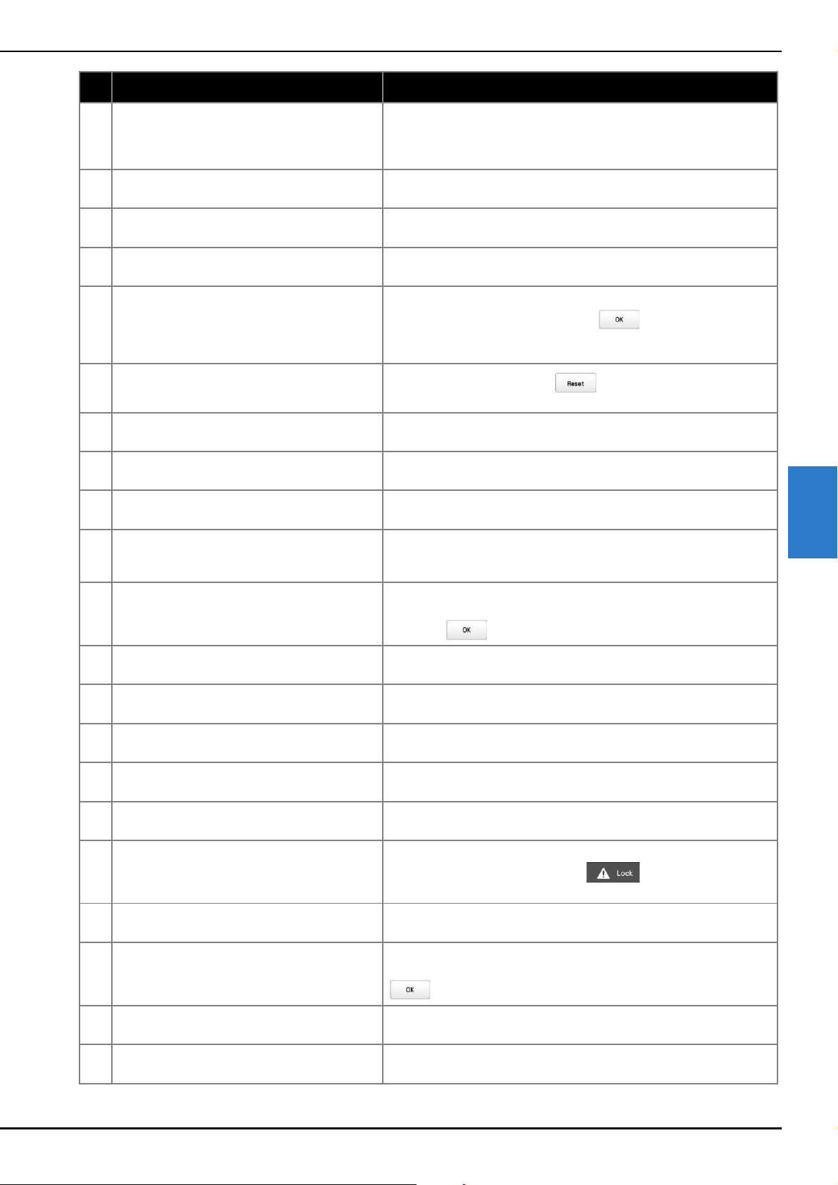
APPENDIX
187
5
31 Needle threader is in threading position. This message is displayed when another operation is performed while the
automatic needle-threading mechanism is threading the needle. Press the
automatic needle-threading button, and then perform the other operation
after the needle is threaded. (page 85)
32 No more patterns can be added to this
combination.
This message is displayed when trying to combine 101 or more patterns. Up
to 100 patterns can be combined.
33 Not enough available memory to save the pattern.
Delete another pattern?
This message is displayed when the pattern cannot be saved because the
memory is full. Delete some patterns.
34 Not enough space. Delete some patterns or use a
different USB media.
This message is displayed when the memory capacity of the USB media has
been exceeded. Delete some patterns or use a different USB media.
35 OK to recall and resume previous memory? This message is displayed when the machine is turned off, then on again
before embroidering is completed. Touch to resume embroidering.
If the embroidering screen was displayed before the machine was turned off,
back up several stitches, and then continue embroidering. (page 97)
36 OK to revert to previous color changes?
This message is displayed when is touched while thread colors are
being changed.
37 OK to separate the combined border pattern? This message is displayed when a combined border pattern is being rotated
in the embroidering settings screen.
38 Panel communication error. When this message is displayed, consult your nearest authorized Brother
dealer.
39 Pattern extends to the outside of embroidery frame.
Add no additional characters.
This message is displayed when the entered character patterns exceed the
width of the embroidery frame.
40 Pattern extends to the outside of embroidery frame.
This function cannot be used at this time.
This message is displayed when the font of the character pattern is changed
to one with a larger size, causing the pattern to extend beyond the
embroidery frame.
41 Picker error This message is displayed when the thread picker (page 33) does not
operate correctly. Remove the thread entangled on the thread picker, and
then touch .
42 Please set up the “Thread antenna” This message is displayed when thread guide assembly support is not
prepared. Prepare the thread guide assembly. (page 19)
43 Power supply voltage error.(24V high) When this message is displayed, consult your nearest authorized Brother
dealer.
44 Power supply voltage error.(24V low) When this message is displayed, consult your nearest authorized Brother
dealer.
45 Power supply voltage error.(40V high) When this message is displayed, consult your nearest authorized Brother
dealer.
46 Power supply voltage error.(40V low) When this message is displayed, consult your nearest authorized Brother
dealer.
47 Press the unlock key to unlock the machine. This message is displayed when the thread trimming button is pressed
before the machine is unlocked. Touch to use the thread
trimming function.
48 Preventive maintenance is recommended. This message is displayed when the machine needs maintenance.
(page 179)
49 Remove the embroidery positioning mark. This message is displayed when the machine has recognized the embroidery
position mark. Remove the embroidery positioning sticker and touch
to continue.
50 Select a pattern. This message is displayed when there is no embroidery pattern selected and
the “Start/Stop” button is pressed.
51 Set the clock. This message is displayed when the time/date is not set. Set time/date.
(page 23)
Error messages Cause/solution
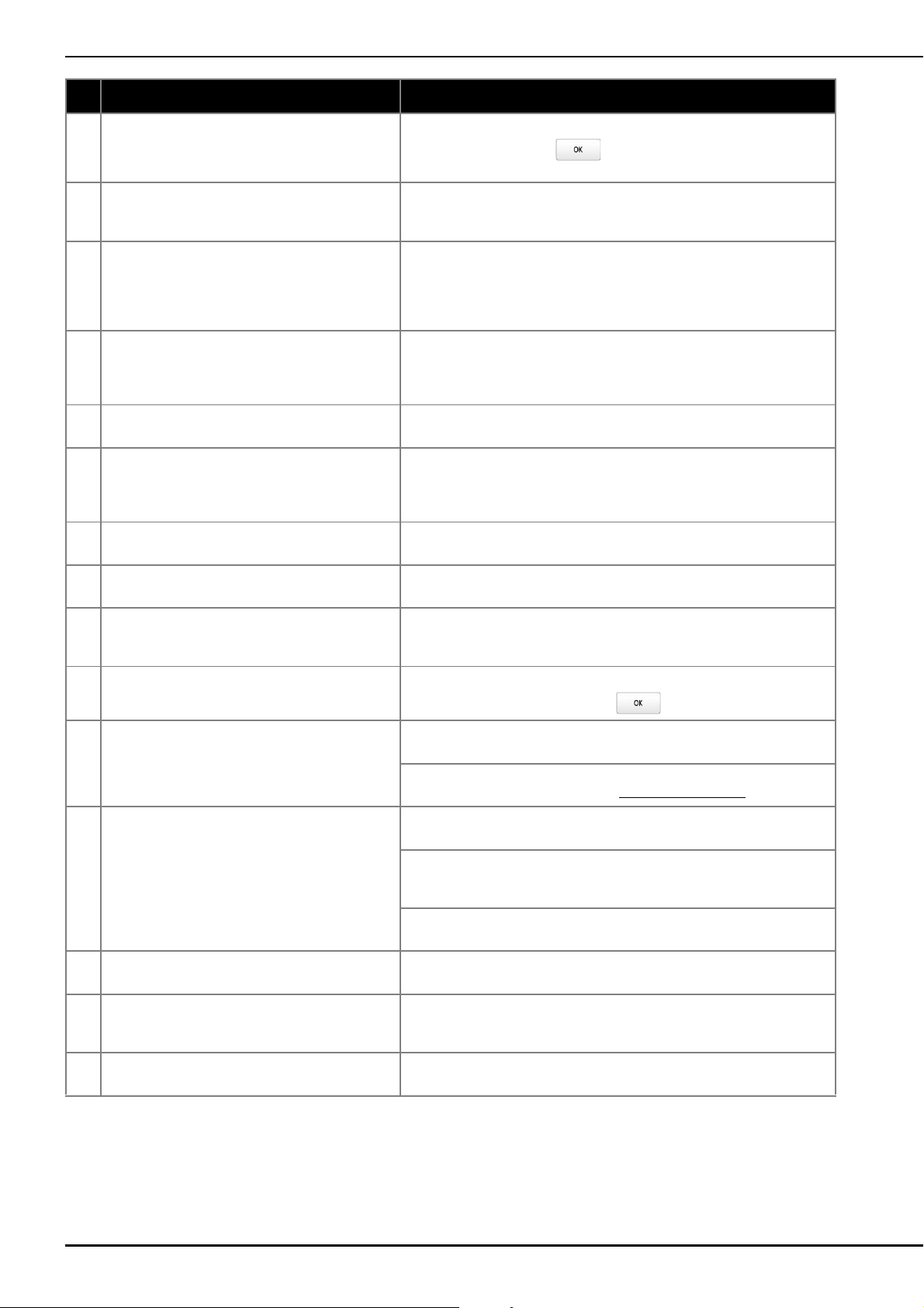
188
52 Stop while needle bar case transferring. This message is displayed when the machine has stopped while the needle
bar case is moving. Touch to automatically reset the needle bar
case.
53 The pattern combination is too large for the extra
large embroidery frame. If you plan to add more
patterns, rotate the pattern combination.
This message is displayed when a long vertical pattern is recalled and no
longer fits in the embroidery frame. Rotate the pattern 90 degrees.
54 The pattern extends out of the pattern area. Change
position of the pattern and scan the new area.
This message is displayed when the built-in camera is being used to align
the embroidery position, but the embroidery positioning sticker is too near an
edge or the pattern extends from the embroidery frame. Change the position
of the embroidery positioning sticker, and then try aligning the position
again.
55 The safety device has been activated. Is the thread
tangled? Is the needle bent?
This message is displayed when a malfunction occurred, such as the thread
becoming tangled or the needle is bent. The machine stops when it detects a
malfunction. Check that the machine is correctly threaded (page 82) and that
the needle is not bent.
56 This file cannot be used. This message is displayed when the file format is incompatible with this
machine. Check the list of compatible file formats. (page 190)
57 This pattern cannot be used since it exceeds the
data capacity.
This message is displayed when the pattern has too many stitches and
cannot be used. Data with stitches that exceed specifications (500,000
stitches) cannot be displayed. Use data design software to reduce the
number of stitches.
58 This pattern cannot be used. This message is displayed when you try to retrieve a pattern that was
downloaded for a different machine.
59 This pattern cannot combine. This message is displayed when a split (large-size) pattern is selected to be
combined with another embroidery pattern.
60 Trimming sensor error. This message is displayed when lint or dust may have accumulated within
the moving knife, the fixed knife, the thread retaining plate, and their
surrounding areas. Clean them. (page 174)
61 USB media error This message is displayed when USB media cannot be read correctly or
when USB media is damaged. Touch and try again.
62 USB media is not loaded. Load USB media. This message is displayed when you tried to recall or save a pattern while no
USB media is loaded. Load USB media.
This message is displayed when you try to use incompatible USB media. For
a list of compatible USB media, visit “ http://s.brother/cpbag/
”.
63 Wiper error This message is displayed when thread is tangled on the wiper. Remove the
tangled thread.
This message is displayed when lint or dust may have accumulated within
the moving knife, the fixed knife, the thread retaining plate, and their
surrounding areas. Clean them. (page 174)
This message is displayed when the thread does not pass through the
groove in the thread cutter. Pass the thread through the groove securely.
64 X-axis home position error. When this message is displayed, consult your nearest authorized Brother
dealer.
65 XY moving error. When this message is displayed, either replace the embroidery frame with a
larger one or return to the pattern editing screen and move the pattern
position.
66 Y-axis home position error. When this message is displayed, consult your nearest authorized Brother
dealer.
Error messages Cause/solution
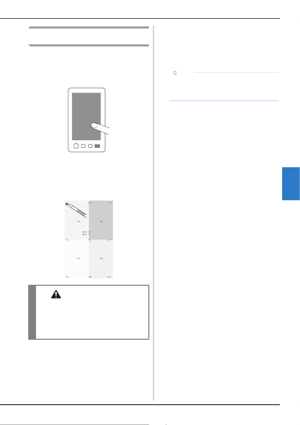
APPENDIX
189
5
If the machine does not respond when a key
is touched
If nothing happens when a key on the screen is touched (no
key can be selected or the keys are misaligned), adjust the
touch panel as described below.
a
Touch anywhere inside the touch panel, and turn the
machine off, then on again.
• Continue touching the touch panel until the screen
shown below appears.
• The “Start/Stop” button is red.
The adjustments screen appears.
b
Use the included touch pen to touch the center of the
numbered crosses on the screen, from 1 to 13.
c
After making the necessary touch panel adjustment,
[SUCCESS] will show on the screen.
• If the buzzer sounds when cross number 13 is
touched, an error occurred during setting, and
[ERROR] appears on the screen. Touch the crosses
again, starting with the number indicated on the
screen.
d
Turn the machine off, and on again.
CAUTION
• Be sure to use the included touch pen to adjust
the touch panel. Do not use a mechanical
pencil, screwdriver or any other hard or sharp
object. Do not apply pressure to the LCD
screen display, otherwise damage to the
display may result.
Note
• If the keys still do not respond, even after the touch
panel is adjusted, or if the touch panel cannot be
adjusted, contact your nearest authorized Brother
dealer.
190
Machine specifications
SPECIFICATIONS
Item Specification
Weight 41.8 kg (92 lb)
Machine size 561 (W) × 589 (D) × 790 (H) mm
(22 (W) × 23-1/4 (D) × 31-1/8 (H) inches)
Embroidery speed Speed range / Max.: 1,000 spm, Min.: 400 spm
Depending on the embroidery frame, maximum stitches in one minute is 600.
Hook Type Vertical fully rotary hook
Hook size Normal size (Type L)
Needle HA130EBBR / #11
Number of needle 10 needles
Thread tension Manual
Thread trimming Upper and bobbin thread
Thread breakage sensor Yes / Upper thread and bobbin thread
Automatic needle
threader
Yes
Connecting your
machine to PC
Compatible interfaces
USB
*1
/ Wireless LAN
*2
Compatible models IBM PC with a USB port as standard equipment
IBM PC-compatible computer equipped with a USB port as standard equipment
Compatible operating
systems
Microsoft Windows 7, Windows 8.1, Windows 10
Memory Embroidery patterns 10 MB
Images can be imported
to the machine (My
Design Center)
100 MB
Data Types
Embroidery patterns
*3
.pes .phc .phx .dst
Data that can be loaded
when using My Design
Center
.jpg .png .bmp
Data Size Embroidery patterns Up to 360 mm (W) × 200 mm (H)
(approx. 14 inches (W) × 7-7/8 inches (H))
.pes files that can be
displayed
Up to 500,000 stitches
Up to 127 color changes
Types of USB Devices/
Media that can be Used
*4
Embroidery patterns Embroidery data can be saved to or recalled from USB media. Use media that
meets the following specifications.
• USB Flash drive (USB Flash memory)
Embroidery data can be recalled only.
• USB external CD/DVD drives
You can also use the following types of USB media with the USB Memory Card
Reader/USB card writer module.
• Secure Digital (SD) Card
• CompactFlash
•Memory Stick
•Smart Media
• Multi Media Card (MMC)
• xD-Picture Card
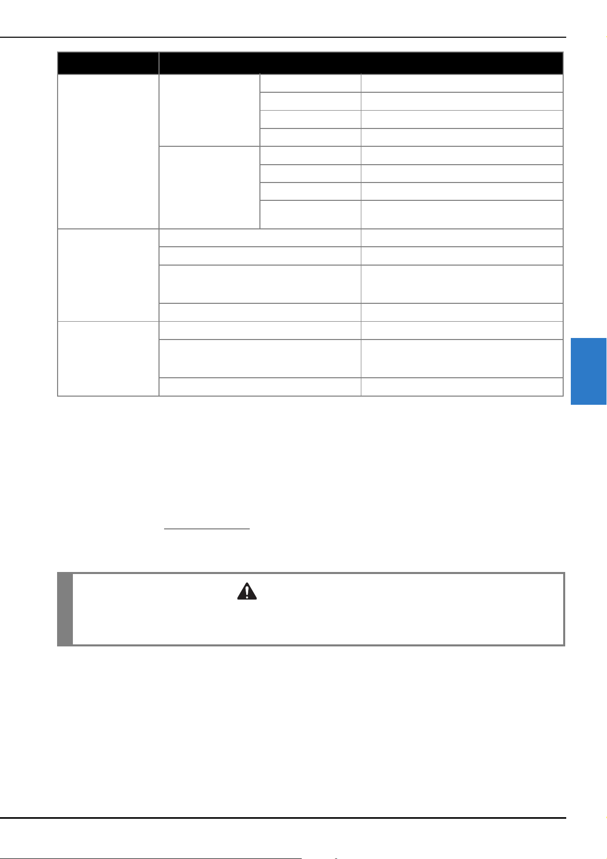
APPENDIX
191
5
*1
Do not create folders in “Removable Disk” on a computer.
If embroidery data is stored in a folder in “Removable Disk”, that embroidery data cannot be retrieved by the machine.
*2
The wireless network connection complies with IEEE 802.11 n/g/b standards and uses the 2.4 GHz frequency.
A wireless network cannot be set up with WPA/WPA2 Enterprise.
*3
Using data other than that saved using our data design systems or this machine may cause this machine to malfunction.
When the machine is used to save a file with any extension, it is saved as a .phx data file.
.dst data is displayed in the pattern list screen by file name (the actual image cannot be displayed).
The full file name may not be displayed depending on the number of characters in the file name.
Since Tajima (.dst) data does not contain specific thread color information, it is displayed with our default thread color sequence.
Check the preview and change the thread colors as desired.
*4
USB media is commercially available, but some USB media may not be usable with this machine.
Please visit our website “ http://s.brother/cpbag/
” for more details.
* Depending on the type of USB devices/media being used, either directly plug the USB device into the machine’s USB port or plug the
USB media Reader/Writer into the machine’s USB port.
* Please be aware that some specifications may change without notice.
Condition of the [Eco
Mode] and [Shutoff
Support Mode]
[Eco Mode] Available time [OFF], 10 - 120 (minute)
“Start/Stop” button Green flashing
Suspended function Machine light, Screen display
After recovering The machine starts from the previous operation.
[Shutoff Support Mode] Available time [OFF], 1 - 12 (hour)
“Start/Stop” button Green slow flashing
Suspended function All functions
After recovering An error message appears.
You need to turn off and on the machine to restart.
Compatible image files of
the Screen Saver Image
Format JPEG format (.jpg)
File size Max. 2 MB for each image
File dimension 1280 (H) × 1200 (W) pixels or less (If the size is more
than 1280 (H) × 800 (W) pixels, the image will be
displayed in a smaller size.)
Number allowed 5 or less
Videos that can be
played
MP4 file format Video - H.264/MPEG-4 AVC, Audio – AAC
Size 1280 (H) × 800 (W) pixels or less (If the size is more
than 450 (H) × 800 (W) pixels, the video will be
displayed in a smaller size.)
Maximum file size 100 MB
Item Specification
CAUTION
• When using embroidery data other than our original patterns, the thread or needle may break when
embroidering with a stitch density that is too fine or when embroidering three or more overlapping
stitches. In that case, use one of our original data design systems to edit the embroidery data.
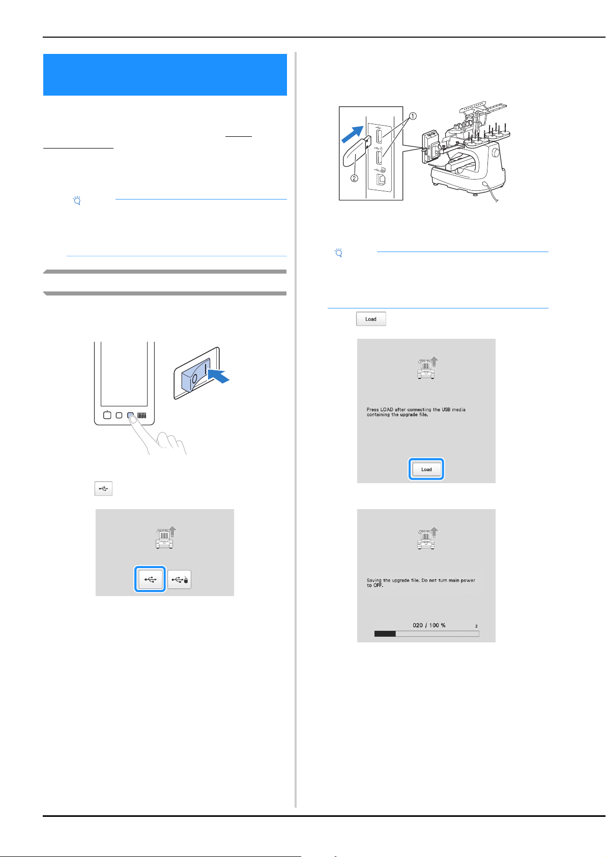
192
You can use USB media to download software upgrades
for your machine.
When an upgrade program is available on “
http://
s.brother/cubah/ ”, please download the files following the
instructions on the website and steps below.
You can use USB to download software upgrades/updates
(**********.upf) for your machine.
Upgrade procedure using USB media
a
While pressing the automatic threading button, turn
the main power to on.
The following screen will appear on the LCD.
b
Touch .
c
Insert the USB media into the USB port on the
machine. The media device should only contain the
upgrade file.
1 USB port
2 USB media
d
Touch .
The upgrade file is downloaded.
UPGRADING YOUR MACHINE’S
SOFTWARE
Note
• When using USB media to upgrade the software,
check that no data other than the upgrade file is
saved on the USB media being used for this
upgrade.
Note
• The access lamp will begin blinking after inserting
USB media, and it will take about 5 to 6 seconds to
recognize the media. (Time will differ depending on
the USB media).

APPENDIX
193
5
e
Remove the USB media, and turn the machine off and
on again.
Note
• If an error occurs, a red text error message will
appear. When the download is performed
successfully, following message will appear.

194
Symbols
“DST” Setting ............................................................................. 123
A
AC adapter ................................................................................. 144
Adjusting
camera view
............................................................................ 73
legs
.......................................................................................... 18
operation panel
........................................................................ 19
scanning results
........................................................................ 73
touch panel
............................................................................ 189
Aligned characters
..................................................................... 128
Appliqué alphabet
....................................................................... 41
Appliqué embroidery
................................................................. 100
Automatic lock stitch
................................................................... 71
Automatic needle-threading button
...................................... 12, 85
Automatic needle-threading mechanism
...................................... 85
B
Background image ....................................................................... 72
Basic procedures
.......................................................................... 33
Basting
......................................................................................... 99
Bobbin case
....................................................................... 33, 175
removing
.................................................................................. 33
Bobbin winder
........................................................................... 142
Border function
............................................................................ 49
Built-in camera
.......................................................... 11, 75, 109
C
Canton fleece ............................................................................... 61
Canvas
......................................................................................... 61
Cap frames
................................................................................... 68
Carriage
....................................................................................... 11
Change thread color key
.............................................. 45, 54, 55
Changing
basting distance
..................................................................... 124
colors of the pattern
................................................................. 54
display guides
........................................................................ 123
position of a sticker
................................................................ 114
thread color display
............................................................... 123
thread density
.......................................................................... 48
Checking
needle bars and thread colors
.................................................. 81
preview image
......................................................................... 60
thread spool changes
............................................................... 91
Cleaning
around the needle plate
......................................................... 174
bobbin case
........................................................................... 175
hook
...................................................................................... 173
LCD
....................................................................................... 173
machine surface
..................................................................... 173
maintenance message
............................................................ 179
oiling machine
....................................................................... 178
thread paths
........................................................................... 175
Clock set
.............................................................................. 23, 24
Color shuffling
............................................................................. 55
Combining patterns
...................................................................... 42
Connecting patterns
................................................................... 109
Corduroy
..................................................................................... 61
Cotton sheeting
............................................................................ 61
D
Delete key ................................................................................... 45
Deleting
short stitches
.......................................................................... 124
Denim
......................................................................................... 61
Density key
.......................................................................... 46, 48
Display guides
........................................................................... 123
Distance from center (horizontal)
................................................ 44
Distance from center (vertical)
..................................................... 44
Dress shirt (woven)
...................................................................... 61
E
Edit end key ................................................................................ 45
Edit key
....................................................................................... 69
Editing
......................................................................................... 44
restart from beginning or middle
.............................................. 96
Embroidering position
align
........................................................................................ 72
Embroidering screen
............................................................. 81, 89
Embroidering settings screen
....................................................... 69
Embroidering time
....................................................................... 90
Embroidery
.................................................................................. 87
aligned characters
................................................................. 128
baseline on the fabric
............................................................ 129
basic method
........................................................................... 87
repeating along a diagonal
.................................................... 127
small fabric
.............................................................................. 64
Embroidery frame
attaching to the machine
......................................................... 64
types
........................................................................................ 66
Embroidery frame holder
attaching
................................................................................. 21
Embroidery frame holders
........................................................... 66
Embroidery frame indicators
......................................... 44, 61, 69
Embroidery key
........................................................................... 70
Embroidery light
.......................................................................... 11
Embroidery patterns
editing
..................................................................................... 44
selecting
.................................................................................. 35
Embroidery positioning sticker
....................... 78, 110, 114, 141
Embroidery sheet
......................................................................... 63
Embroidery thread
....................................................................... 82
Error messages
........................................................................... 185
F
Fabric Thickness Check ........................................................ 25, 74
Fabric/stabilizer compatibility chart
............................................. 61
Feet
............................................................................................. 11
Forward/Backward stitch key
........................................ 89, 93, 96
G
Going back through the stitching .......................................... 93, 96
Golf shirt
..................................................................................... 61
Grouping
..................................................................................... 43
H
Handwheel ................................................................................. 11
Headwear
................................................................................... 61
Hook
......................................................................................... 173
Hook cover/Hook
........................................................................ 11
Hooping
...................................................................................... 62
Horizontal mirror image key
....................................................... 46
I
Included accessories ................................................................... 12
J
Jumbo frame .............................................................................. 140
INDEX

APPENDIX
195
5
Jump code ................................................................................. 123
Jump stitch trimming
................................................................. 123
L
LCD ..................................................................................... 12, 24
Lingerie or silk
............................................................................. 61
Link function
............................................................................. 132
Lock stitching key
................................................................ 69, 71
Locking the needle bar
................................................................ 80
Lower thread guide
...................................................................... 11
M
Magnetic sash frame .......................................................... 52, 108
Main power switch
.............................................................. 11, 22
Manual color sequence
............................................................... 58
Maximum embroidery speed key
................................................. 89
Middle thread guide
.................................................................... 11
Monitoring App
........................................................................... 32
My Design Center
...................................................................... 147
N
Needle
threading
................................................................................. 85
Needle bar case
........................................................................... 11
Needle bar key
.................................................................... 81, 90
Needle bar/Frame move key
........................................................ 24
Number of thread color changes
................................................. 69
O
Oiling ........................................................................................ 178
Operation panel
........................................................... 11, 12, 19
Optional accessories
................................................................... 14
P
Pattern display area ..................................................................... 24
Pattern editing screen
.................................................................. 44
Pattern selection keys
.................................................................. 46
Pattern size
.......................................................................... 44, 69
Positioning keys
................................................................... 46, 70
Power supply cord
............................................................. 22, 144
Power supply plug
....................................................................... 11
Preview key
......................................................................... 45, 70
Previewing the image
.................................................................. 60
Q
Quilting borders ........................................................................ 105
R
Region display ............................................................................. 89
Remaining length
...................................................................... 124
Reserve stop key
................................................................ 89, 119
Reserved needle
................................................................ 25, 121
Restart from beginning
......................................................... 93, 96
Resume embroidering
.................................................................. 97
Return key
................................................................................... 89
Rotate key
........................................................................... 45, 69
Rotation angle
............................................................................. 44
S
Satin jacket .................................................................................. 61
Scan
.......................................................................................... 156
Selecting
embroidery pattern
.......................................................... 35, 42
Setting remaining length
.............................................................. 25
Setting up
.................................................................................... 16
Short stitch delete
.............................................................. 25, 124
Silk
.............................................................................................. 61
Size (horizontal)
........................................................................... 44
Size (vertical)
............................................................................... 44
Size key
....................................................................................... 45
Speaker
........................................................................................ 12
Specifications
............................................................................. 190
Split (large-size) patterns
............................................................ 135
Spool
........................................................................................... 82
Spool change indicator
........................................................ 89, 91
Spool stand
.......................................................................... 11, 20
Stabilizer
.............................................................................. 60, 61
Start/Stop button
.................................................................. 12, 87
Starting/ending position key
..................................... 70, 126, 127
Stitch count
.................................................................................. 90
Stitch simulator screen
................................................................. 60
Stopping embroidering
................................................................. 88
at color changes
..................................................................... 119
pause
..................................................................................... 119
Sweater knit
................................................................................. 61
Sweatshirt
.................................................................................... 61
T
Tajima data ................................................................................ 123
Temporary needle bar setting key
...................................... 89, 120
Terms of Use
.................................................................................. 5
Terry cloth
................................................................................... 61
Thread
......................................................................................... 82
Thread color display
.................................................................. 123
Thread color sequence display
..................................................... 89
Thread color set up display
.......................................................... 90
Thread density
............................................................................. 48
Thread guide
........................................................................ 11, 83
Thread guide assembly
................................................................ 19
Thread guide pins
........................................................................ 11
Thread mark
................................................................................ 51
Thread spools
easily changing
........................................................................ 92
Thread tension disc
...................................................................... 84
Thread tension knobs
......................................................... 11, 118
Thread trimming button
....................................................... 12, 88
Thread trimming key
.................................................................... 47
Threading
bobbin thread
.......................................................................... 33
needle
...................................................................................... 85
upper thread
............................................................................ 81
Touch pen holder
........................................................................ 11
Trial embroidery key
.................................................................... 70
Troubleshooting
......................................................................... 179
T-shirt
.......................................................................................... 61
Tubular frame table
...................................................................... 73
U
Uninterrupted embroidering (one color) ..................................... 120
Unlock key
.................................................................................. 89
Upgrading machine’s software
................................................... 192
USB media
............................................................................. 192
Upper thread guide
...................................................................... 11
Upper thread guide pretension knob
.......................................... 118
Upper threading
................................................................... 81, 82
USB port
computer connection
............................................................. 130
USB media connection
.......................................................... 130
USB mouse connection
............................................................ 32
V
Ventilation slots ........................................................................... 11
Version
........................................................................................ 26
W
Wide table ......................................................................... 73, 137


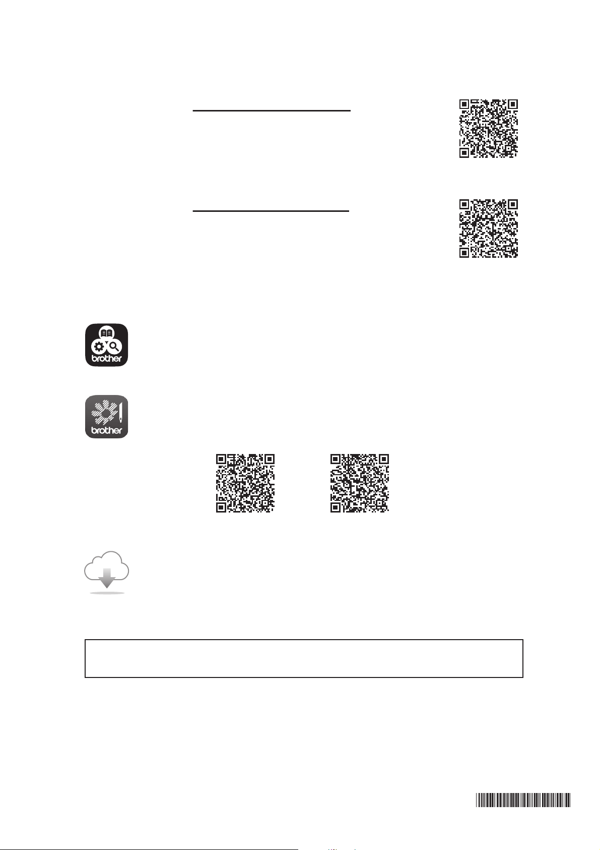
Please visit us at http://s.brother/cpbag/ where you
can get product support and answers to frequently asked
questions (FAQs).
This machine is approved for use in the country of purchase only. Local Brother companies or
their dealers will only support machines purchased in their own countries.
Be sure to install the latest software.
A variety of functional improvements are being performed in the latest version.
Brother SupportCenter is a mobile app that provides the support information for
your Brother product.
My Stitch Monitor is a mobile app that monitors the operating conditions of your
machine.
Visit the Google Play™ or App Store to download.
Please visit us at http://s.brother/cvbak/ to view
Instruction Videos.
Google Play™ App Store
English
884-T15
XH5035-001