Loading ...
Loading ...
Loading ...
12 13
INSTALLATION INSTRUCTIONS
1- INSTALLING THE COOKTOP
A. Remove the screws on the sides of the cooktop burner box. Use those
screws to attach the side mounting brackets.
B. Insert the cooktop centered into the cutout opening. Make sure the front
edge of the countertop is parallel to the cooktop. Check clearances at the
front, back and sides. Secure the hold-down bracket to the cabinet sides with
screws.
2- INSTALL PRESSURE REGULATOR
A. Screw the regulator onto the burner box bottom pipe connection. Make
sure the top of the regulator is facing toward the cabinet front and the arrow
on the back of the regulator points to the cooktop.
B. Complete the connection between the regulator and the shut-off valve.
C. Before testing for leaks, make sure all burner knobs are in the OFF position.
After connecting the cooktop to gas, check system for leaks with a manom-
eter. If a manometer is not available, turn the gas supply on to the cooktop
and use a liquid leak detector at all joints and connections to check for leaks.
Tighten all connections if necessary to prevent gas leakage in the cooktop or
supply line.
-Disconnect the cooktop and its individual shut-off valve from the gas supply
piping system during any pressure testing of that system at test pressures
greater than 1/2 psig (3.5 kPa).
-Isolate the cooktop from the gas supply piping system by closing its individ-
ual shut-off valve during any pressure testing of the gas supply system at test
pressures equal to or less than 1/2 psig (3.5 kPa).
3- CONNECT ELECTRICAL
·Check to be sure the receptacle is properly grounded.
·Plug in the power cord.
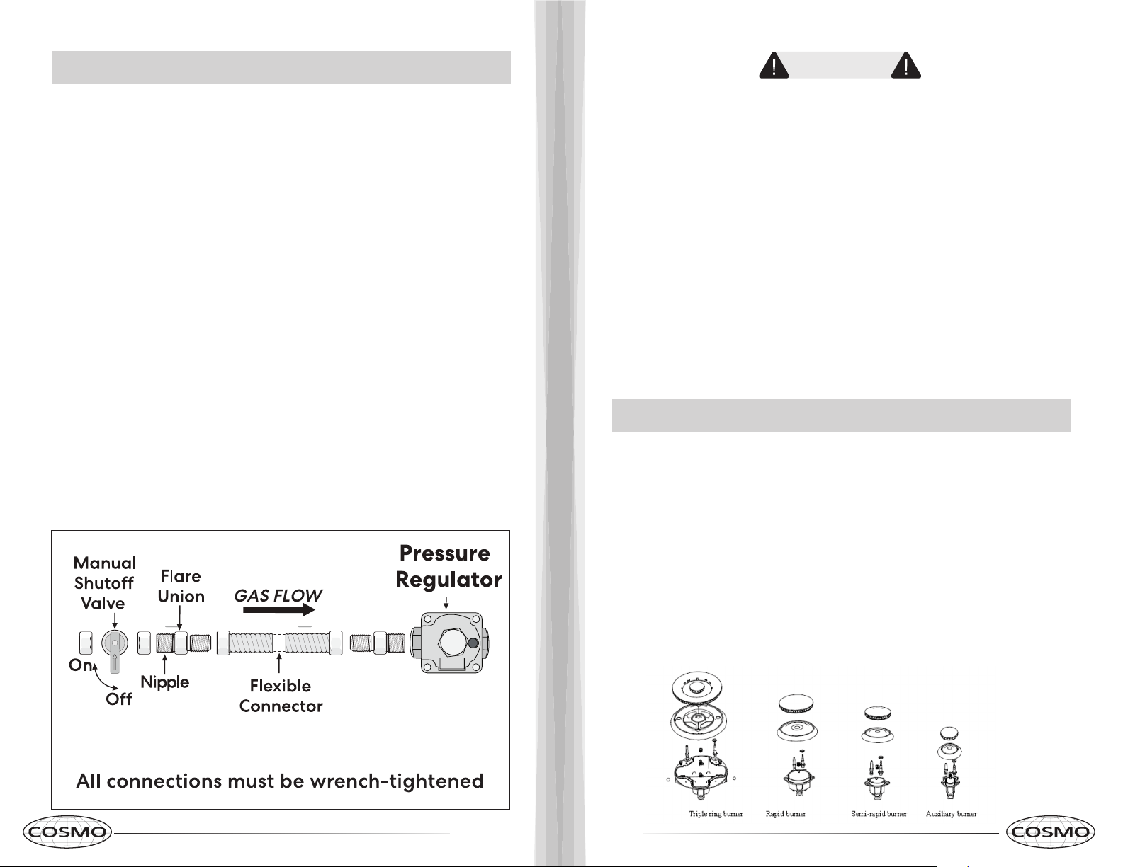
ASSEMBLE BURNERS, CHECK IGNITION
The electrode of the electronic ignition system is positioned above the surface
of the burner base. Do not remove a burner cap or touch the electrode of
a burner while another is turned on. Damage or electrical shock may occur.
A) The electrode of the electronic ignition system is positioned above the surface
of the burner base. Do not remove a burner cap or touch the electrode of a
burner while another is turned on. Damage or electrical shock may occur.
B ) Place burner heads over the burner base. Make sure the hole in the burner
head is properly aligned with the electrode in the burner base.
C ) Place the burner caps on the burner heads. Make sure that the burner
caps are properly seated on the burner heads. Burner cap properly seated
Burner cap not properly seated
IMPORTANT: If the igniter electrodes continue to spark after all of the burners
are lit, check that each burner component is assembled and properly seated.
• Never reuse old flexible connectors. The use of old flexible connectors can
cause gas leak and personal injury. Always use new flexible connectors
when installing a gas appliance.
• To reduce the possibility of gas leaks, apply Teflon tape or a thread
compound approved for use with LP or Natural gas to all threaded
connections.
• Do not use a flame to check for leaks.
WARNING
Loading ...
Loading ...
Loading ...