
Introduction 2
Instrumentation 4
Lights 12
Driver controls 23
Seating and safety restraints 44
Driving 60
Roadside emergencies 70
Cleaning 76
Maintenance and specifications 79
Customer assistance 92
Warranty information 98
Index 110
All rights reserved. Reproduction by any means, electronic
or mechanical including photocopying, recording or by any
information storage and retrieval system or translation in
whole or part is not permitted without written
authorization from Ford Motor Company. Ford may change
the contents without notice and without incurring
obligation.
Copyright © 2001 Ford Motor Company
Table of contents
1

The following warning may be required by California
law:
CALIFORNIA Proposition 65 Warning
Warning: This product contains or emits
chemicals known to state of California to
cause cancer and birth defects or other
reproductive harm.
ICONS
Indicates a safety alert.
Read the following
section on warnings.
WARNINGS
Warnings provide information which may reduce the
risk of personal injury to you and others.
BREAKING IN YOUR VEHICLE
There are no particular break-in schedules for the
vehicle.
Proper charging and avoidance of over discharging of
the batteries will enhance their lives and capacity.
Make sure to read Battery charging in the Driving
section of this manual and Batteries in the
Maintenance and specifications section of this manual.
Introduction
2
These are some of the symbols you may see on your
vehicle.
Safety Alert
Fasten Safety Belt
Brake System
Master Lighting Switch
INFORMATION ABOUT THIS GUIDE
The information found in this guide was in effect at
the time of printing. Ford Motor Company and/or
TH!NK Mobility, LLC may change the contents
without notice and without incurring obligation.
Introduction
3
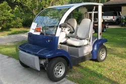
GAUGES
The instrument cluster LCD (liquid crystal display)
will be activated if any of the following conditions
exist:
• Key switch is on
• Vehicle batteries are being recharged
1. Safety belt warning
indicator
The safety belt
warning icon will
illuminate for 30
seconds after the
vehicle is switched into D (Drive) mode.
2. Speedometer gauge
LCD
A two-digit LCD gauge
display shows the
vehicle speed in either
MPH or Km/h,
depending on the selected mode. Vehicle speed is
shown while in R (Reverse) and D (Drive) modes.
The top speed of your vehicle is 25 mph
(40 km/h).
1 2
13
3
12
11
10 9 8 7
6
5
4
Instrumentation
4
3. Right turn signal
indicator
The arrow will flash when the turn signal lever is
pushed up. If the indicator flashes at a fast rate, it
has a malfunction, such as a burned out bulb.
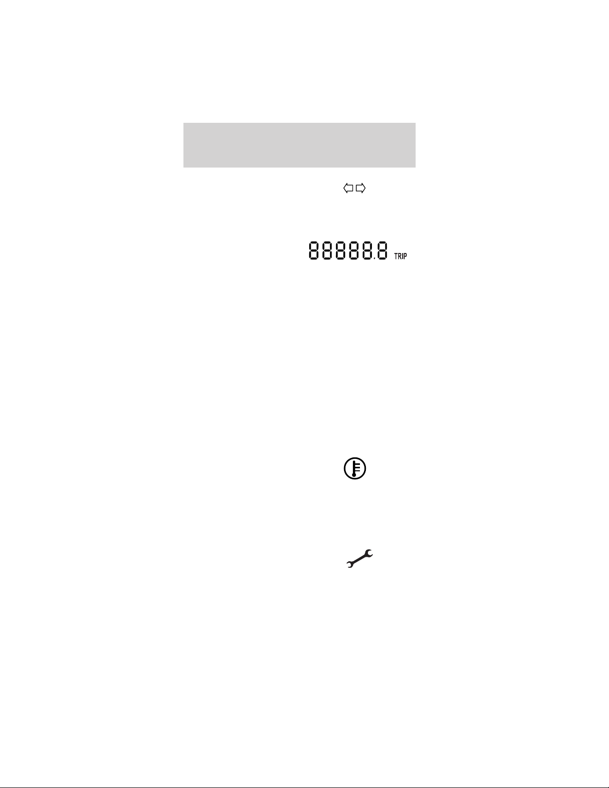
4. Odometer/trip counter
display
A five-digit LCD
display includes a tenth decimal digit to show the
total accumulated miles traveled. The display may
be changed to measure a particular trip distance.
The drive mode selector switch must be in the T
(Turf) or D (Drive) mode for this function. When
the vehicle is restarted, the display will return to
the last mode manually set.
Changing and resetting the modes
The odometer/trip modes can be changed by
pressing the Select/Reset button on the instrument
cluster. The word “TRIP” will be displayed next to
the five-digit display when in Trip mode. To
measure a specific trip mileage, with the drive
mode selector switch in T (Turf) or D (Drive) reset
the trip odometer by pushing and holding the
Select/Reset button down for three seconds.
5. Drive system
over-temperature indicator
This icon will illuminate if
the drive system
overheats. The vehicle will drive normally during
this 30-second period. Power will be limited after
the 30-second period and will remain limited until
the drive system cools.
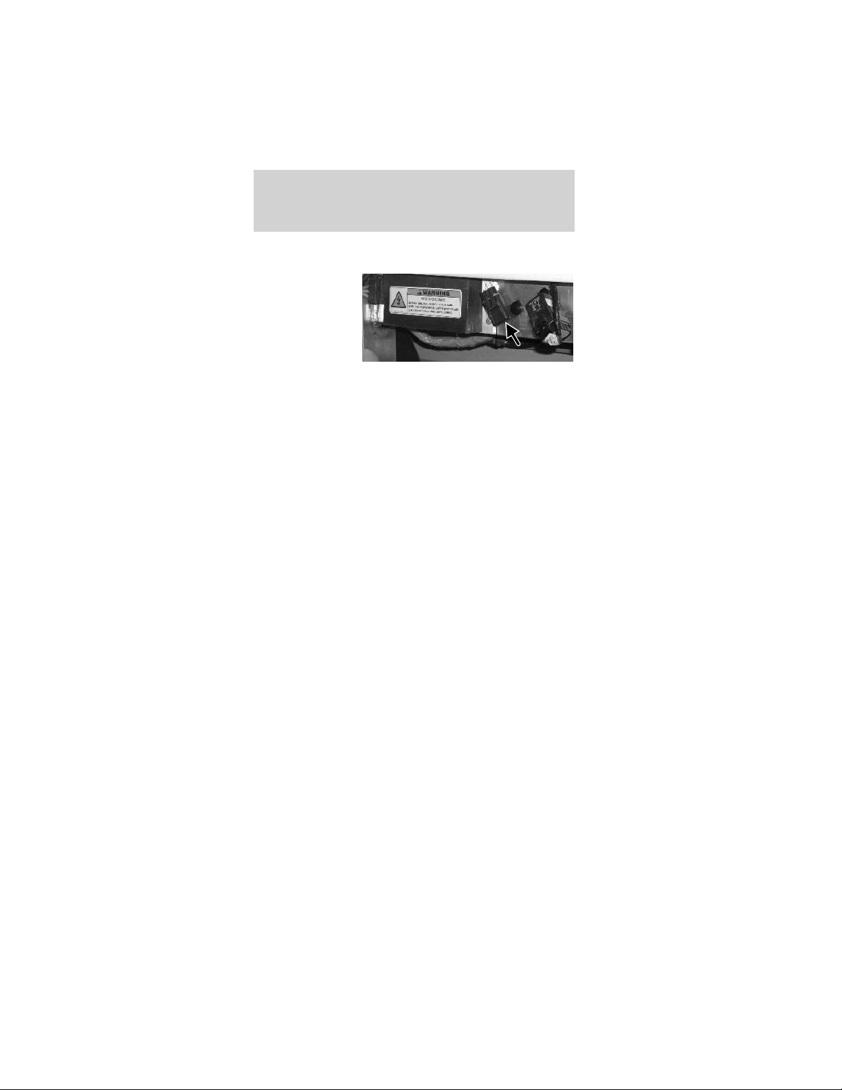
6. Service required indicator
The icon will illuminate when
the vehicle has a malfunction
in the motor controller. Cycle the service
disconnect switch off and then back on. The
service disconnect switch is located below and
Instrumentation
5

behind the parking brake lever within the seat
stanchion (battery cover). It is a black rubber
switch and faces the front of the vehicle. To
access the service disconnect switch, remove the
seat stanchion front cover, refer to Flooded type
bateries in Maintenance and specifications.If
the vehicle is still on, take your vehicle to an
authorized Dealer for the required maintenance to
maintain your full warranty coverage.
7. Battery water
reminder indicator
This icon indicates
that your vehicle’s
batteries require a
maintenance check of
the fluid levels. Distilled water or
demineralized water must be added as
needed. Your vehicle comes equipped with one of
two types of batteries: “flooded”, requiring water
level checks and maintenance refills; or the
optional sealed maintenance free, for which no
maintenance is required. This indicator will be
disabled if your vehicle is equipped with sealed
batteries. If you change the type of battery in your
vehicle, the TH!NK dealer will need to change the
battery setting in the gauge.
Resetting the battery water reminder indicator
Once the battery water has been checked, reset
the reminder by pressing and holding the
Select/Reset button for over three seconds while
in the R (Reverse) mode. The reminder will only
be reset during the following conditions: R
(Reverse) mode is selected with the drive mode
selector switch; instrument cluster gauge is in
flooded battery mode and the battery water
reminder indicator is active.
Reverse alarm
When the vehicle is in R (Reverse), a tone is
generated to alert the driver.
Instrumentation
6

8. System Select/Reset
button
This button is used to
perform four
functions.
a. Each time the
Select/Reset button is pressed and released in less
than three seconds, the odometer/trip counter will
switch between odometer and trip function
displays. The drive mode selector switch must be
in the D (Drive) or T (Turf) mode for this
function.
b. Pressing and holding the Select/Reset button,
with the odometer in the trip mode, for over 3
seconds before releasing will reset the trip
odometer to zero and return to the trip odometer
function. The drive mode selector switch must be
in the D (Drive) or T (Turf) mode for this
function.
c. Pressing and holding the Select/Reset button for
over three seconds will reset the battery water
reminder indicator. The drive mode selector
switch must be in the R (Reverse) mode and the
instrument cluster must be in “battery flooded
mode” for this function.
d. The Select/Reset button will allow you to
display diagnostic code(s). To display the
diagnostic code(s):
• With the key in the OFF position, press and hold
the Select/Reset button.
• Select D (Drive) mode with the key.
• Release the Select/Reset button.
• Press and release the Select/Reset button to scroll
through the diagnostic codes and their
corresponding odometer value.
• All codes will be deleted by holding the
Select/Reset button for three seconds and
releasing.
Instrumentation
7

• Exit Service mode by selecting the OFF mode
with the key.
• Press and release the Select/Reset button.
The following is a list of diagnostic codes.
Fault
Code
Description
05 Start switch fails to close.
08 Accelerator input voltage too low on power up
after initial key switch closure.
09 Both forward and reverse direction switches are
closed at the same time.
15 Battery voltage is too low at initial drive mode
selector switch closure.
16 Battery voltage is too high or control card is
misadjusted.
23 Motor field current is high on start up in the
reverse direction.
24 Motor field current is high on start up in the
forward direction.
27 12V buss is too low.
41 Open thermal protector (TP) or transistor
over-temperature.
42 Motor armature offset voltage is too high.
43 Motor armature offset voltage is too low.
44 Armature transistor did not turn off properly.
45 Armature transistor did not turn on properly.
46 “Look Ahead” test for A2 volts less than 12% of
battery volts.
49 Motor field current is too low during the run
mode.
51 Capacitor volts are low before the line contactor
closes.
57 Controller “motor current sensor” input too low
while running.
76 Capacitor (1C) voltage too high during
regenerative braking.
90 Motor thermostat is open during control operation.
Instrumentation
8
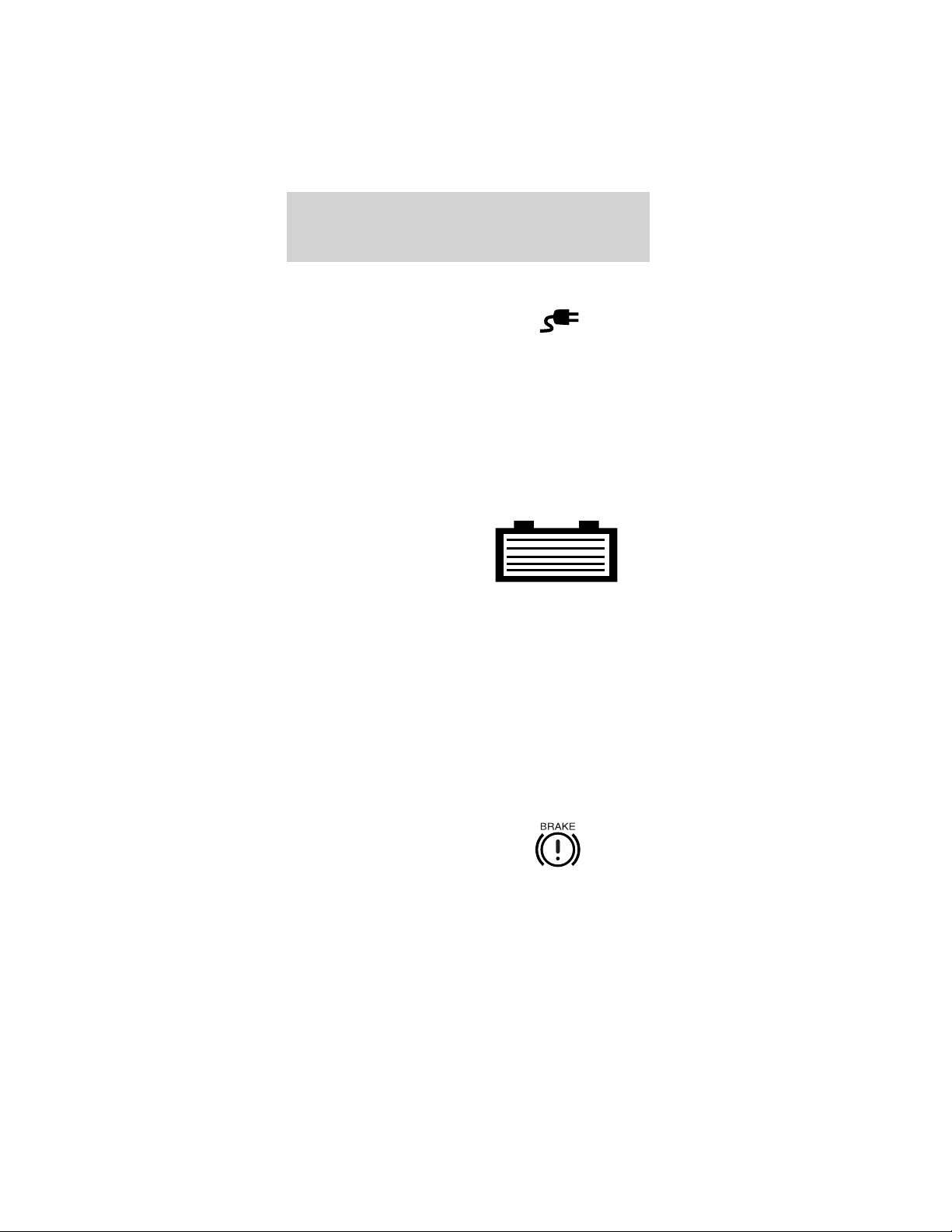
9. Battery charge
indicator
The icon will
illuminate when the
vehicle is connected
to an outside power
source to charge the batteries. The drive mode
selector switch should be in the OFF position
while the battery is charging.
Note: If this indicator is illuminated without the
vehicle being charged there is a charger problem.
The vehicle should be taken to an authorized
TH!NK dealer.
10. Battery level
indicator
The battery level
indicator shows the
power level remaining
in the batteries. Five
bars are illuminated when the batteries have a full
charge. When there are zero bars showing, the
batteries have been discharged to the point where
additional operation of your vehicle will reduce
battery life. Charge the vehicle batteries
immediately. If left uncharged, the batteries could
discharge to the point where the battery charger
will not turn on.
After a partial charge, the level may read higher
than it actually is. Driving a few miles will cause
the battery gauge to settle to an accurate level.
11. Brake status
indicator
This icon will
illuminate if the
emergency brake
handle is not fully
released, or if the brake fluid level is low. It will
also flash while the park brake reminder is
sounding.
Instrumentation
9
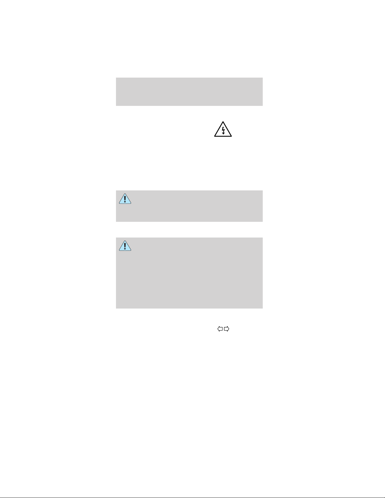
12. Electrical leakage
warning indicator
This icon will
illuminate to warn
that there is electrical
“leakage” or short
circuit to the vehicle frame. If the vehicle is wet
or has recently been washed, allow the vehicle to
fully dry and recheck for the indicator. If the
indicator is still present, take your vehicle to an
authorized TH!NK Dealer to correct the condition.
To avoid serious injury and/or death, never
perform any vehicle service or maintenance
while the electrical leakage warning indicator is
illuminated.
This vehicle contains a high voltage
electrical system. Serious injury, death,
and/or property damage may result if this vehicle
is not properly used, charged or serviced as stated
in this manual. Read this owner’s guide prior to
use, charging, or servicing this vehicle. Do not
drill, cut, or modify any part of this vehicle, as
high voltage wiring is present. Do not use jumper
cables. Only charge this vehicle with an approved
GFCI cord as stated in Battery charging.
13. Left turn signal
indicator
The arrow will flash
when the turn signal lever is pushed down. If the
indicator flashes at a fast rate, it has a
malfunction, such as a burned out bulb.
Instrumentation
10

Audible Indicators
Park brake reminder
The park brake reminder has a tone that sounds for
10 seconds when the drive mode selector switch is
turned to the OFF position with the parking brake
not set. It stops after 10 seconds or when the
parking brake is engaged. During this time the
vehicle is “active” with functional park brake
reminder and the gauge will be active and backlit.
After 10 seconds, the vehicle shuts down and park
brake reminder is no longer functional.
To avoid serious injury, death, and/or
property damage, always engage the parking
brake before leaving the vehicle.
Reverse alarm
When the vehicle is in R (Reverse), a tone is
generated to alert the driver and pedestrians.
Instrumentation
11
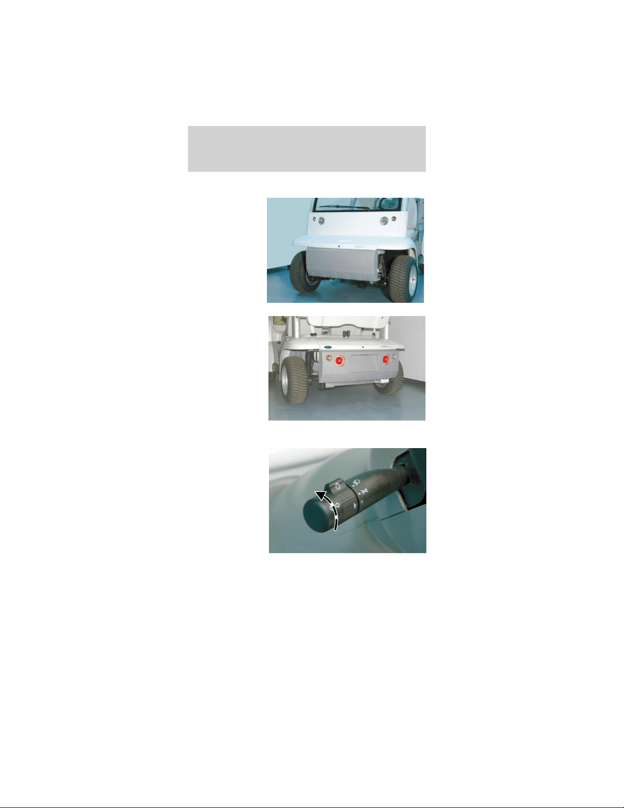
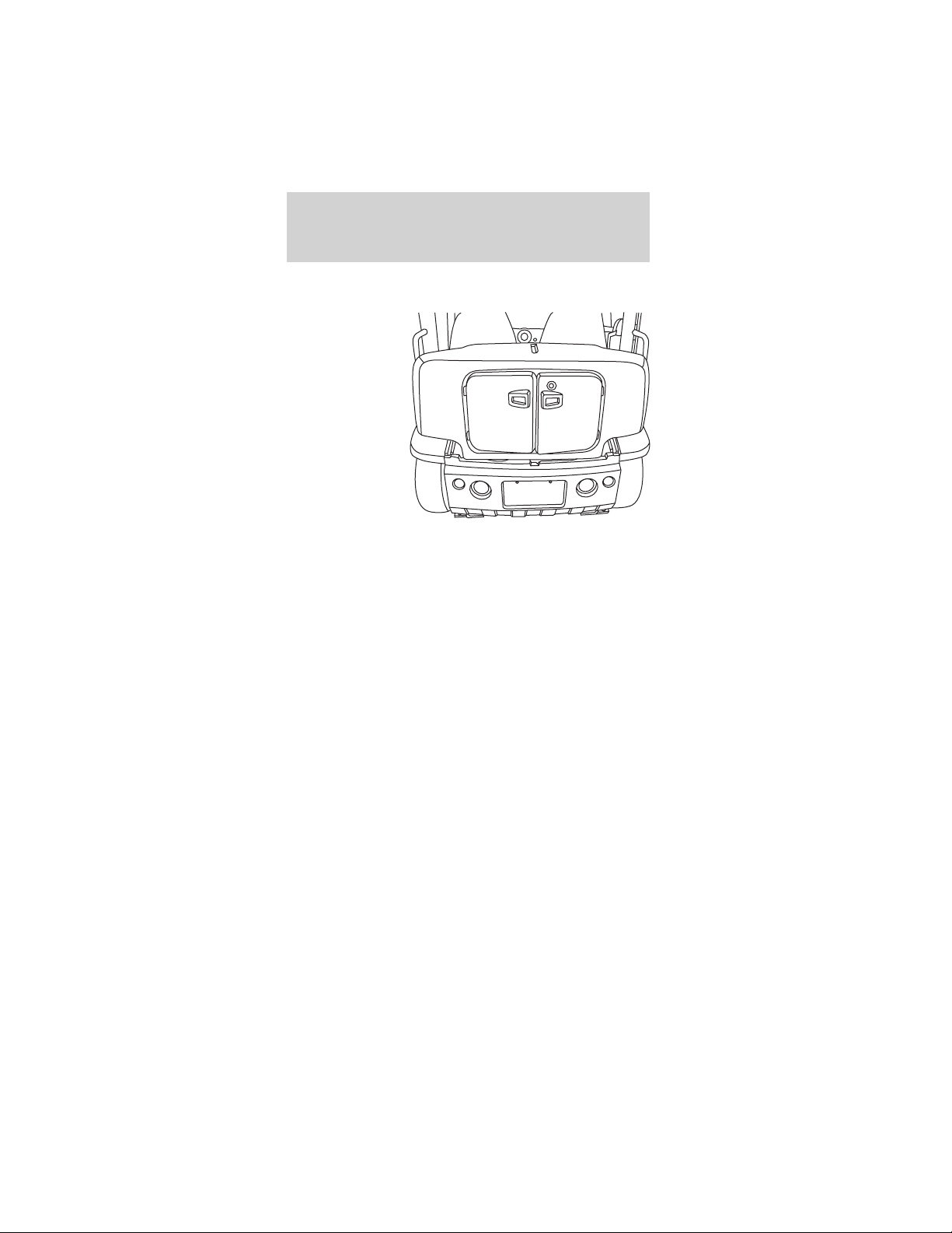
HEADLAMP CONTROL
The headlamps
are the larger
inboard lamps
on the front
panel of the
vehicle. The
smaller
outboard lamps
are the front
turn signals.
The headlamp
switch also
controls the tail
lights. The tail
lights are the
larger inboard
lamps
integrated into
the rear
bumper. The
smaller
outboard lamps are the rear turn signal lamps.
The headlamp
switch is
located on the
lever on the left
side of the
steering
column. The
center section
of the lever
rotates to turn
on the parking
lamps and the headlamps.
Lights
12

The headlamp switch
can be identified by the
bright bulb symbol.
Always remember to turn on your
headlamps at dusk and dawn and during
inclement weather. Failure to activate your
headlamps under these conditions could result in a
collision.
The OFF position is
indicated on the lever by
the O. When the switch
arrowhead is aligned
with the O symbol, the
exterior lamps are off.
The first position above
the OFF position is the
parking lamps.
The second position
above the OFF position
will illuminate the
headlamps while the
parking lamps remain
on.
Pulling the headlamp switch rearward while it is in
the OFF position will cause the headlamps to flash.
There are no high beams on this vehicle. Pulling the
headlamp switch rearward while it is in the ON
position will NOT change the performance of the
headlamps.
Lights
13
TURN SIGNAL CONTROL
The headlamp
switch lever also
controls the
turn signals.
Push down to
activate the left
turn signal, and
push up to
activate the
right turn signal.
The appropriate
arrow indicator will flash on the instrument cluster
indicating that the turn signal is on.
AIMING THE HEADLAMPS
The headlamps on your vehicle are properly aimed
at the assembly plant.
If your vehicle has been in an accident the alignment
of your headlamps should be checked by a qualified
service technician.
Vertical aim adjustment
1. Park the vehicle on a level surface approximately
7.6 meters (25 feet) from a vertical wall or screen
directly in front of it.
• (A) 2.43 meters (8 feet)
• (B) Height of top of lamp beam to ground
• (C) 6.09 meters (25 feet)
• (D) Horizontal reference line
Lights
14
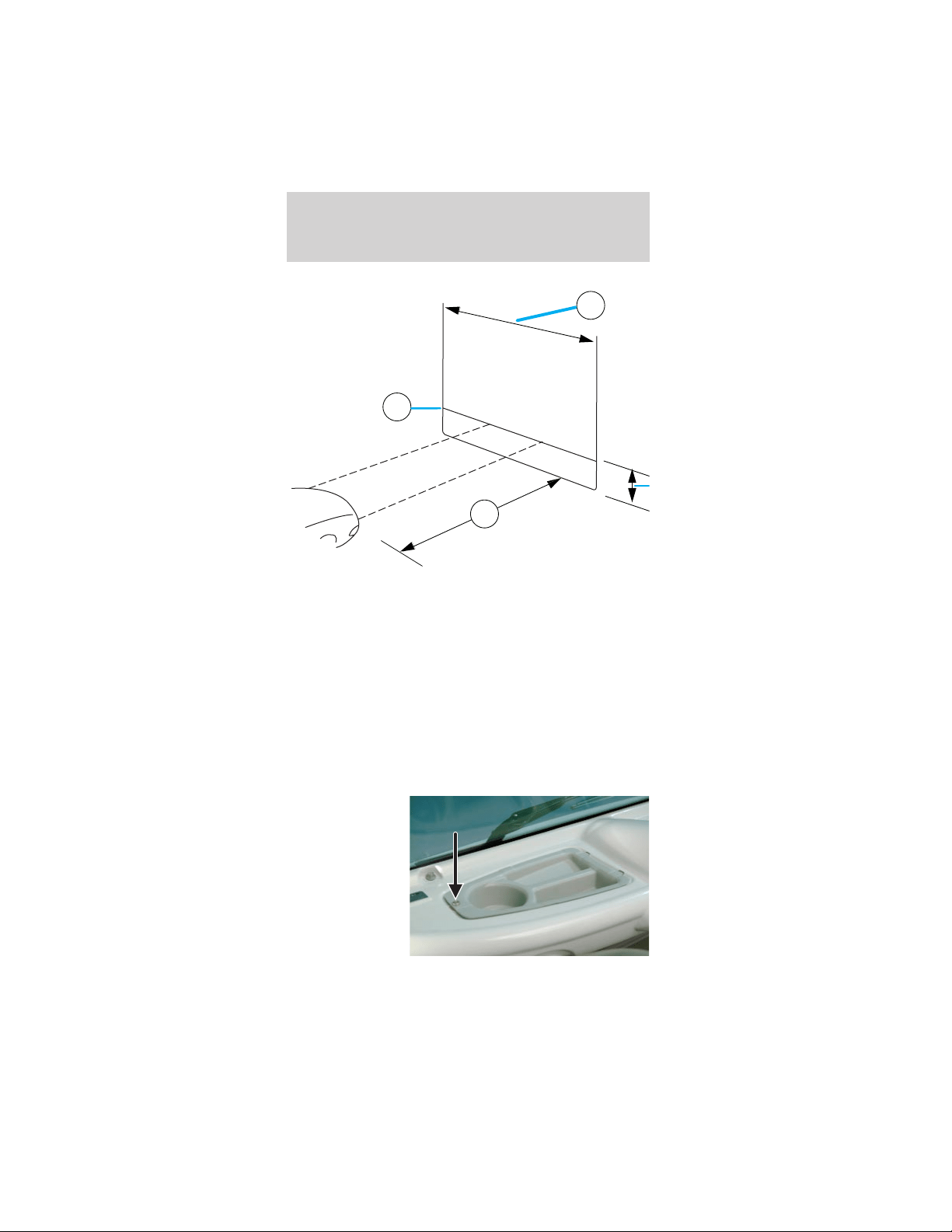
2. Turn on the headlamps to illuminate the wall or
screen.
3. On the wall or screen you will observe an area of
high intensity light. The top of the high intensity
area should be .381 meters (2 ft 3 in) above the
ground. If not, the beam will need to be adjusted by
a qualified TH!NK technician.
BULB REPLACEMENT
Headlamps
To remove the headlamp bulb:
1. Remove the
scrivet and the
cowl tray panel.
A
D
C
Lights
15
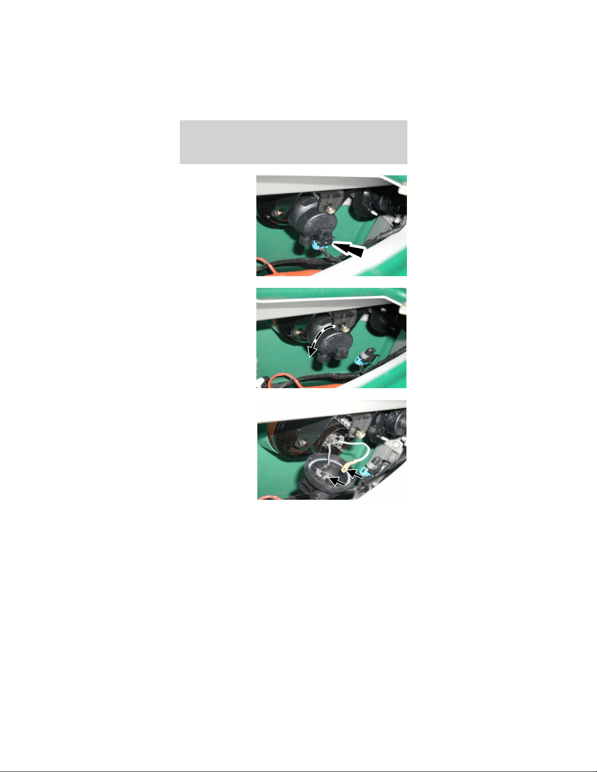
2. Disconnect
the headlamp
electrical
connector.
3. Rotate the
headlamp bulb
shield
counterclockwise
and flip down
to access the
bulb
connectors.
4. Pull the flat
connector
attached to the
white wire from
the headlamp
bulb shield.
Lights
16
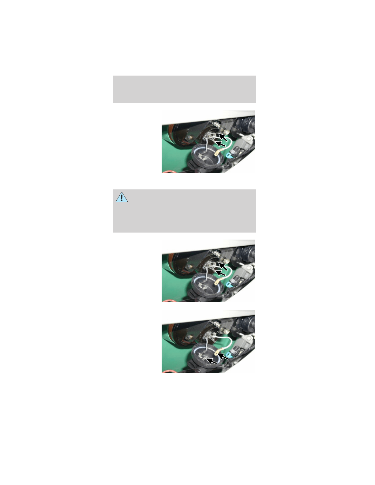
5. Push and
squeeze the two
bulb retainer
wires to
disengage them
from the
headlamp
housing.
Remove the
headlamp bulb.
To install the headlamp bulb:
Handle the halogen headlamp bulb carefully
and keep out of the children’s reach. Grasp
the bulb only by its metal base and do not touch
the glass. The oil from your hand could cause the
bulb to break the next time the headlamps are
operated.
1. Install the
headlamp bulb.
Squeeze and
push the two
bulb retainer
wires to engage
them to the
headlamp
housing.
2. Push the flat
connector
attached to the
white wire into
the headlamp
bulb shield.
Lights
17
3. Install and
rotate the
headlamp bulb
shield
clockwise.
4. Connect the
headlamp
electrical
connector.
5. Install the
cowl tray panel
and the scrivet.
Lights
18
Replacing the front turn signals
1. Remove the
scrivet and cowl
tray panel.
(Driver side
shown; the
passenger side
is similar.)
2. Twist counterclockwise and remove the front turn
signal bulb retainer.
3. Remove the bulb.
4. Install the new bulb.
5. Install the removed
components.
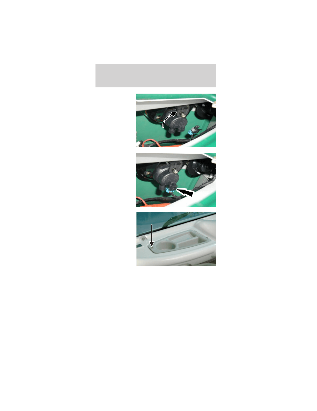
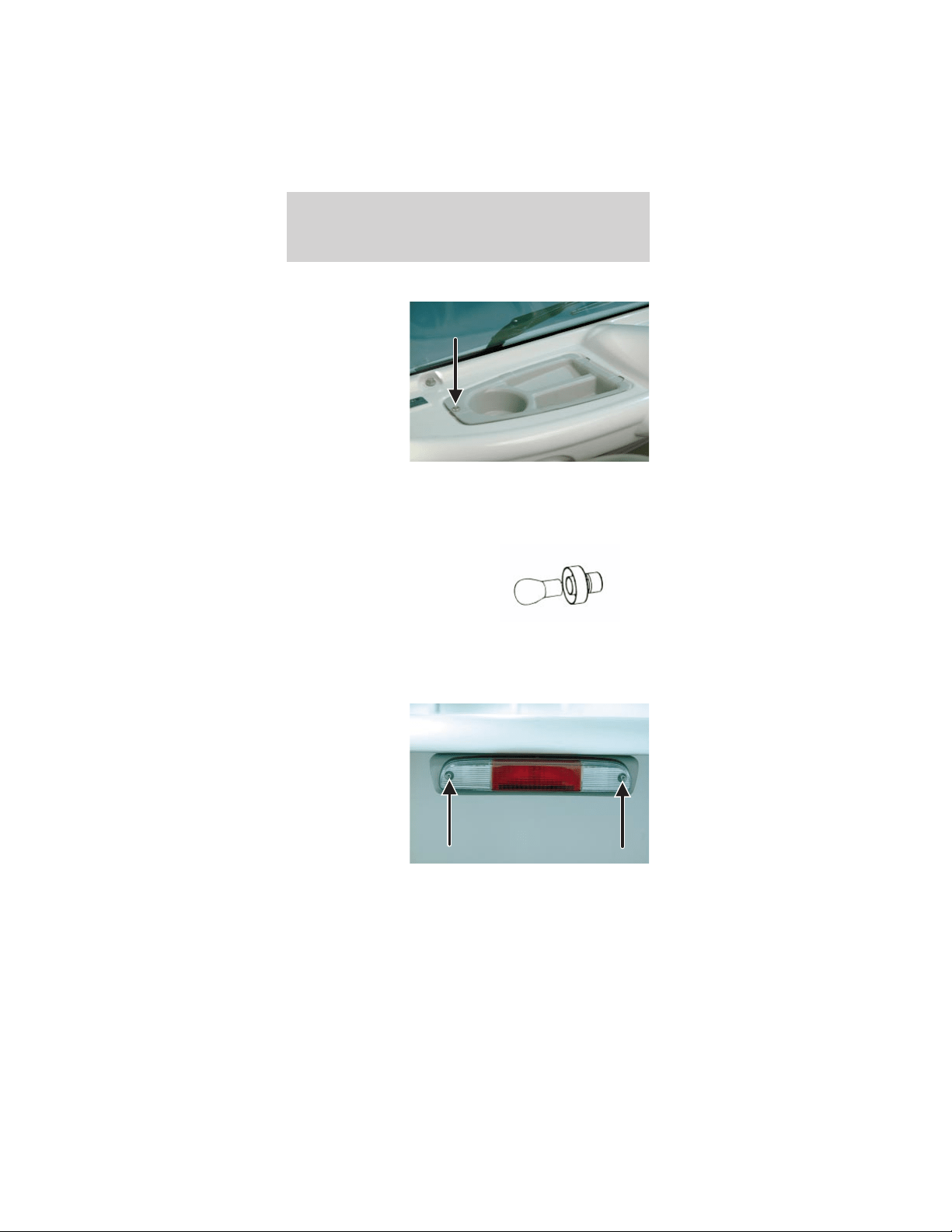
Replacing the rear high-mount stop and reverse
lamp bulbs
1. Remove the
two screws and
pull out the
lamp assembly
to expose the
bulb sockets on
the back.
Lights
19
2. Rotate the
bulb socket
counterclockwise
and pull out to
access the bulb.
3. To remove the bulb, pull it straight out of the
socket.
4. Insert a new bulb into the socket until it is fully
seated.
5. Install the socket into the back of the lamp
assembly and turn clockwise until it is locked into
place.
6. Position the lamp assembly into the vehicle
housing and install the two screws. Tighten the
screws firmly, but do not over-tighten.
Over-tightening can cause damage to the lamp.
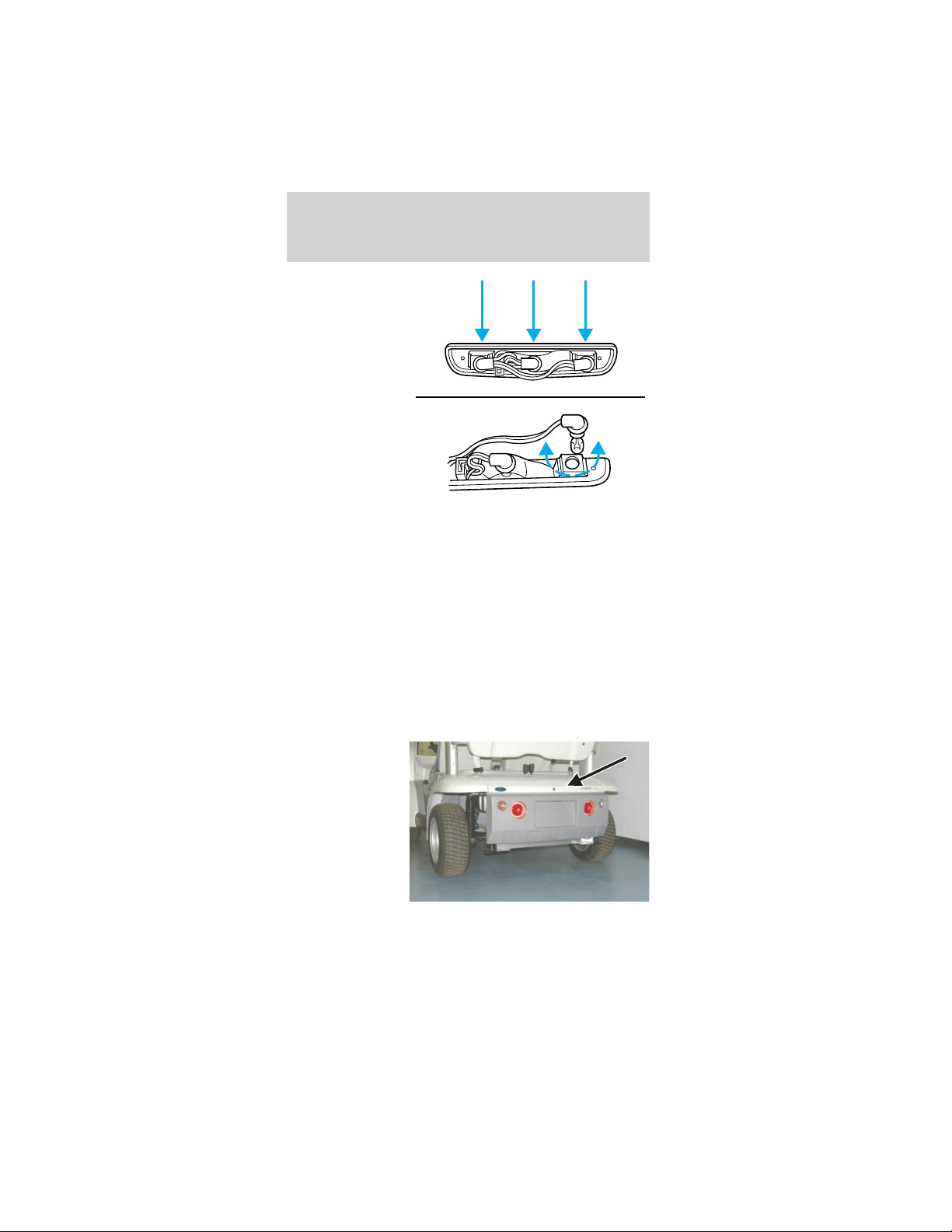
Replacing the rear turn signals
1. Unlock and
remove the
decklid.
2. From inside
the rear wheel
housings,
remove the six
rear bumper
bolts and
carefully lower
the bumper.
Lights
20
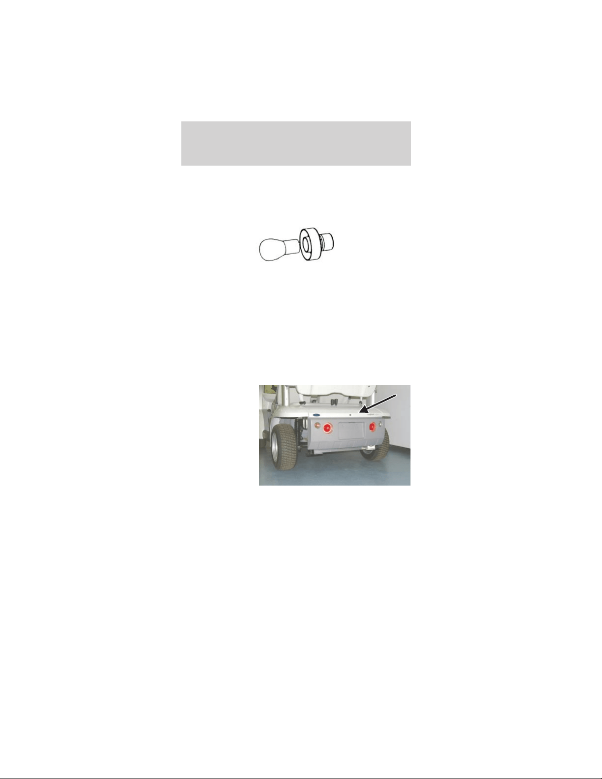
3. Twist counterclockwise and remove the rear turn
signal bulb retainer.
4. Remove the bulb.
5. Install the new bulb.
6. Install the removed parts. Tighten the rear
bumper bolts to 8–10 N•m.
7. Install and lock the decklid.
Replacing the tail lights/brake lights
Note: The bulb in the tail light/brake light assembly
is not serviceable. The entire assembly must be
replaced.
1. Unlock and
remove the
decklid.
2. Disconnect the electrical connector.
Lights
21
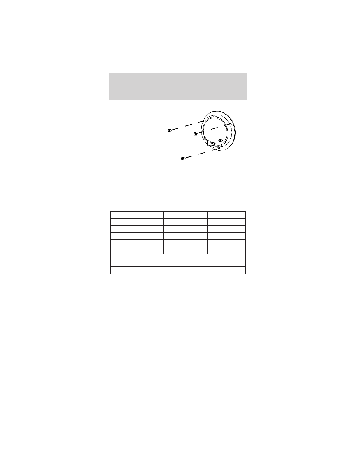
3. Remove the
three screws
and the rear
turn signal
assembly.
4. Connect the
electrical
connector and
install the new
lamp assembly.
5. Tighten the screws firmly, but do not over-tighten.
6. Install and lock the decklid.
Using the right bulbs
Replacement bulbs are specified in the chart below.
Function Number of bulbs Trade number
Headlamp 2 H3
Backup lamp 2 906
License plate lamp 1 W5W
High-mount stop lamp 1 922
Turn signal lamp 4 7507/PY21W
All replacement bulbs are clear in color except where
noted.
To replace all instrument panel lights - see your Dealer.
Lights
22
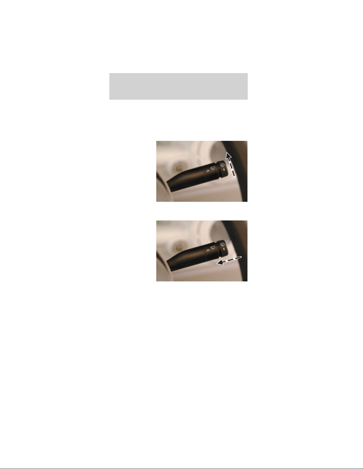
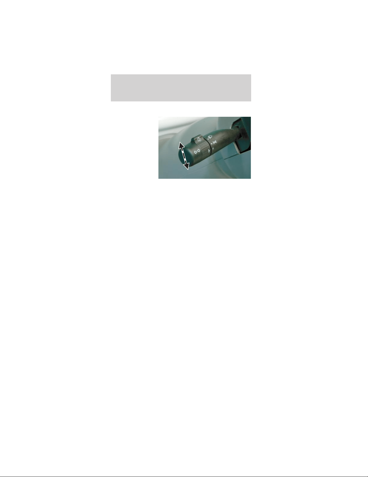
WINDSHIELD WIPER/WASHER
Front wiper control
The front windshield wiper is controlled by the lever
mounted on the right side of the steering column.
To operate the
windshield
wiper, with the
drive mode
selector switch
in R (Reverse),
T (Turf) or D
(Drive), push
the lever up.
Washer
To operate the
windshield
washer, turn
the wiper on,
push the end of
the lever in
toward the
steering column
and hold it in
for the desired
length of spray.
Release the lever to stop the washer and turn the
wiper off.
Driver controls
23
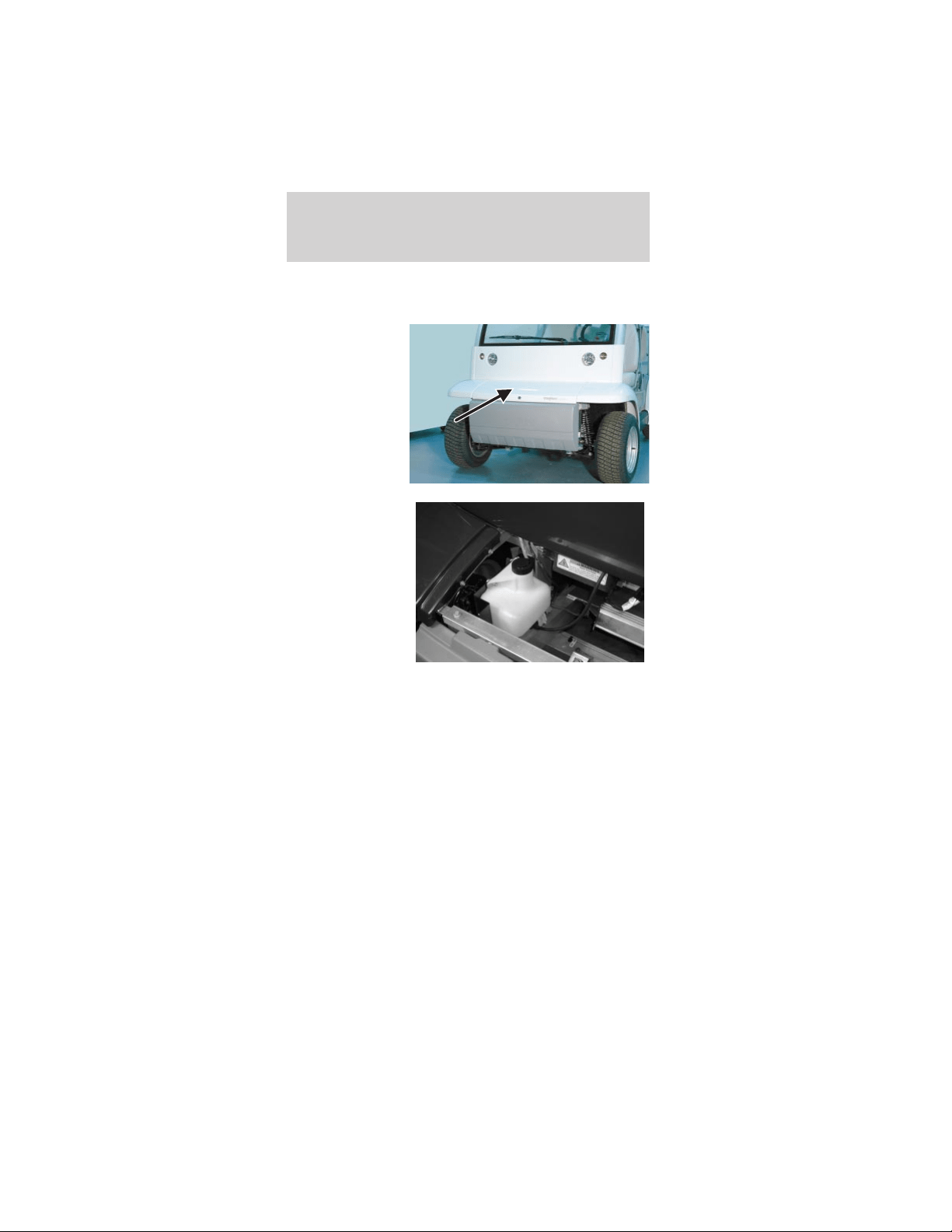
Checking windshield washer fluid
To check the windshield washer fluid level:
1. Unlock and
remove the
hood.
2. Observe the
level of fluid in
the reservoir on
the right side of
the
compartment.
3. If necessary, unscrew the reservoir cap and fill
with pre-mixed washer fluid.
4. Install the reservoir cap.
5. Install and lock the hood.
Checking the wiper blade
If the wiper operation results in streaky or
obstructed vision, clean the blade with mild soap
and water to remove any foreign material, grease or
dirt. If the wiper operation still results in poor
visibility, inspect the blade, the insert, and the arm.
• Confirm that the arm and blade are not bent or
damaged. If any defect is found, the part must be
replaced to assure proper operation.
Driver controls
24
• Confirm that the wiper blade insert is supple and
pliable. If it has become hard, cracked, or split it
must be replaced for proper operation.
SUN ROOF/ROOF VENT (IF EQUIPPED)
The sun
roof/roof vent is
located in the
roof panel.
Opening it
increases air
flow to the
driver and front
passenger.
To open the sun roof/roof vent:
1. Pull down on the sun roof/roof vent handle to
unlock the sun roof/roof vent.
2. Rotate the handle rearward and swivel up until it
locks in one of the five raised positions.
To close the sun roof/roof vent:
1. Pull down on the sun roof/roof vent handle to
unlock the sun roof/roof vent.
2. Rotate the handle forward and swivel up until it
locks in the closed position.
FRONT
Driver controls
25
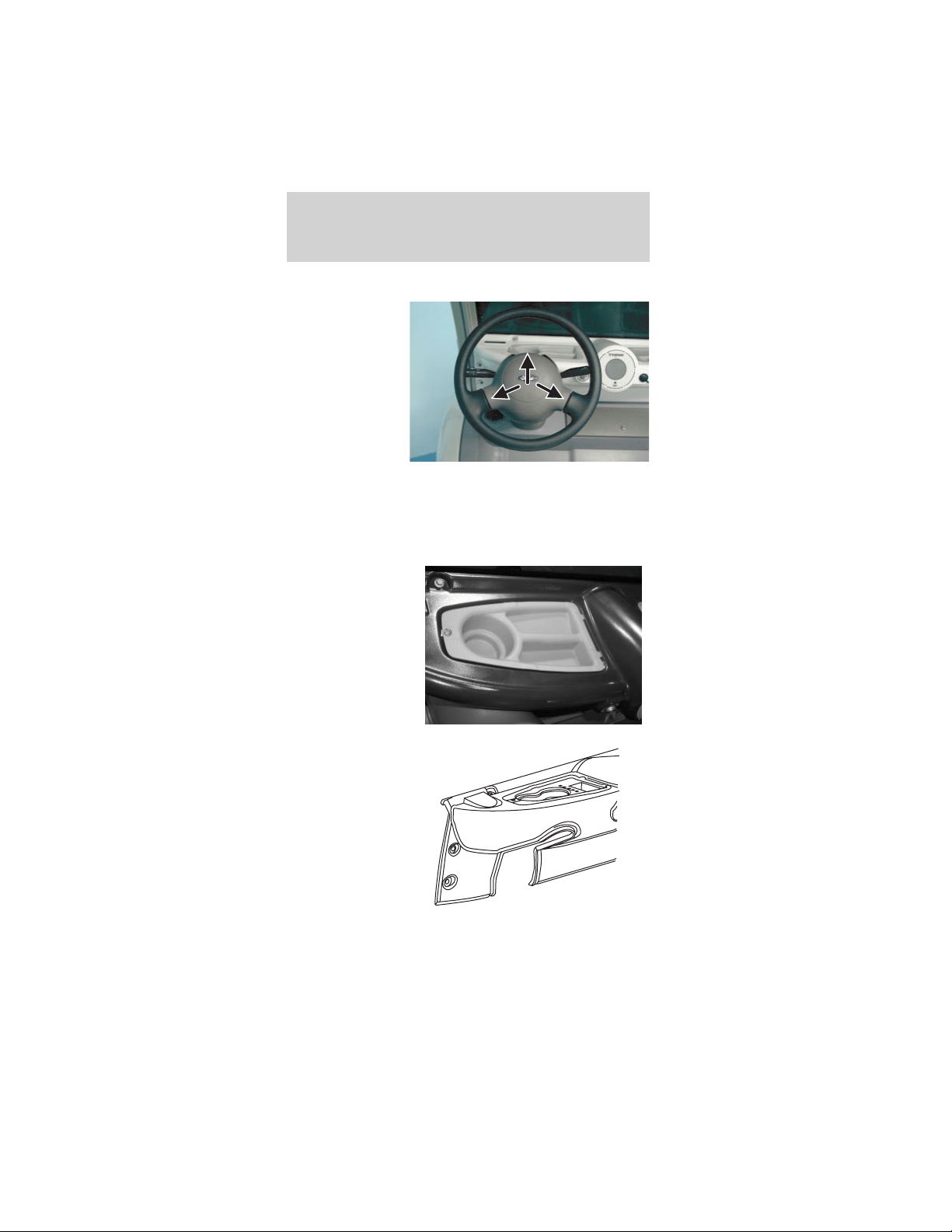
HORN
To activate the
horn, push one
of the three
horn contact
points on the
steering wheel.
CUPHOLDER
Your vehicle is equipped with a number of
convenient cupholders, depending on which storage
trays your vehicle has.
Driver side
instrument
panel storage
tray with
cupholder and
storage
compartments
(Passenger side
is similar.)
Optional cowl
tray with sport
package.
Driver controls
26
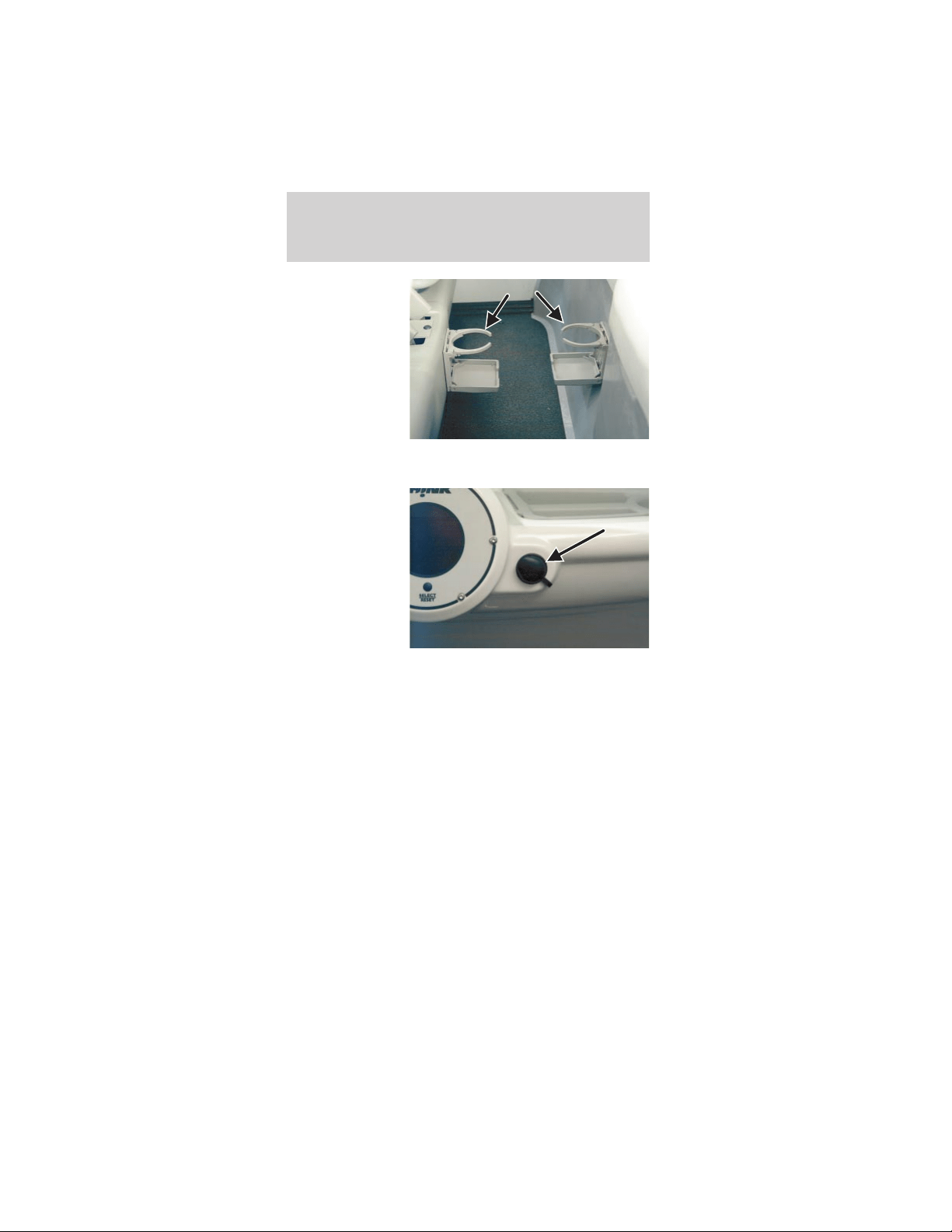
Rear cupholders
(4-passenger
only)
15 A POWER POINT (IF EQUIPPED)
The 15A power
point is located
on the
passenger side
of the
instrument
panel. The
power point is
operational at
all times. For
safety, there is
a rubber plug protecting the power point. To use the
power point, remove the rubber plug and insert the
desired accessory plug. Always keep the rubber plug
inserted into the power point when not in use.
Note: The power point should not be used during
battery charging.
MIRRORS
Interior rear view mirror
The interior rear view mirror is adjustable for both
day and night use. To reduce the glare at night, use
the manual switch at the base of the mirror to put
the mirror in night mode.
Driver controls
27
Exterior mirror
The exterior rear view mirrors (right-hand mirror is
optional) are adjusted manually. Your view should be
adjusted so that the vehicle’s rear tires are just
visible in the bottom inside corner of the mirror.
This will minimize any “blind spot” in your field of
view.
Always confirm it is clear behind you before
changing lanes or backing up to avoid a
collision.
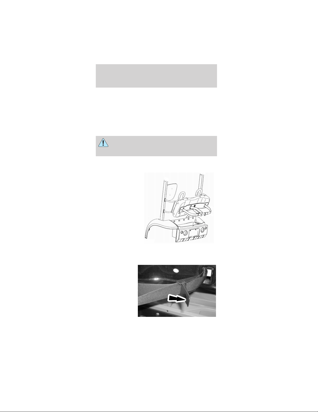
GOLF RACK (IF EQUIPPED)
To mount golf
bags in the golf
rack:
1. Unlock the decklid. To remove the decklid, lift
and raise the decklid.
2. Pull rearward
on the bag belt
webbing
release/locking
lever.
Driver controls
28
3. Pull the webbing out of the release/locking lever.
Note: The base of the golf bag should rest on the
top of the golf bag tray.
4. Position the golf bag in the trunk area.
5. Route the webbing through the golf bag handle
and through the release/locking lever.
6. Remove any slack from the webbing and lock the
release/locking lever.
FLOOR MATS
The floor mats are fastened to the floor with scrivets
that can be loosened and removed for cleaning
under the floor mats.
SCORECARD HOLDER (IF EQUIPPED)
The scorecard holder is attached to the glove box
door with magnets.
STEREO (IF EQUIPPED)
For operating instructions for the stereo, please refer
to the instructions provided with the unit.
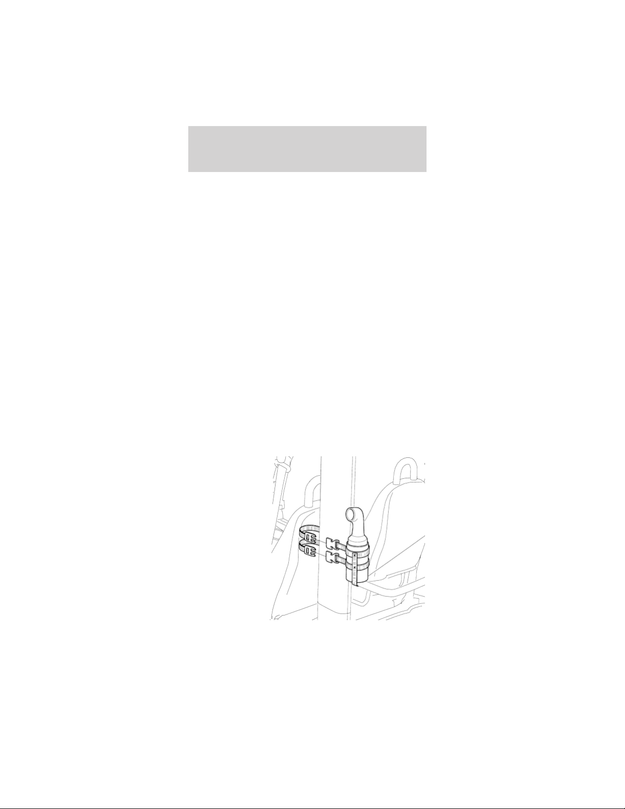
SAND AND SEED BOTTLE AND HOLDER
(IF EQUIPPED)
The sand and
seed bottle
holder is
mounted to the
left-hand side
roof pillar.
Driver controls
29
BALL AND CLUB WASHER (IF EQUIPPED)
The ball and club washer is mounted to the
left-hand side roof pillar.
To drain and fill the ball and club washer:
1. Remove the
front and rear
rubber plugs.
Let the old
water drain.
2. Remove the five screws from the bottom of the
cover. Remove the cover.
Driver controls
30
3. Remove and
rinse the
cleaning
brushes.
4. Rinse out any dirt or remaining soap.
5. Install the cleaning brushes.
6. Install the front and rear rubber plugs.
7. Fill with a water and soap solution.
8. Install the cover and screws. Tighten the screws,
but do not overtighten.
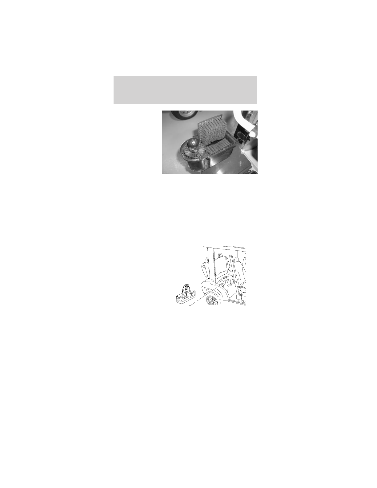
COOLER (IF EQUIPPED)
The cooler is a
removable
folding soft
cooler. On
4-passenger
neighbors, the
cooler is located
under the rear
seat. On
2-passenger
neighbors, the
cooler is located in the storage tray.
Driver controls
31
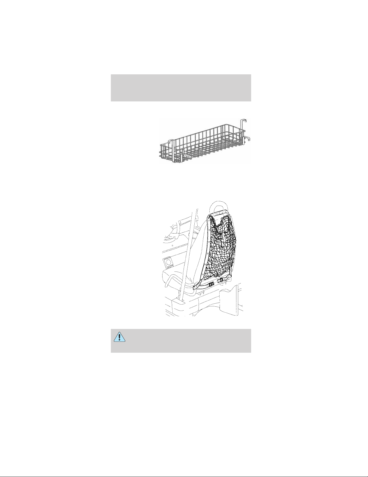
SWEATER BASKET (IF EQUIPPED)
The sweater
basket is
mounted to a
bracket
between the
rear roof
B-pillars.
Note: The sweater basket should not be used to
carry heavy objects.
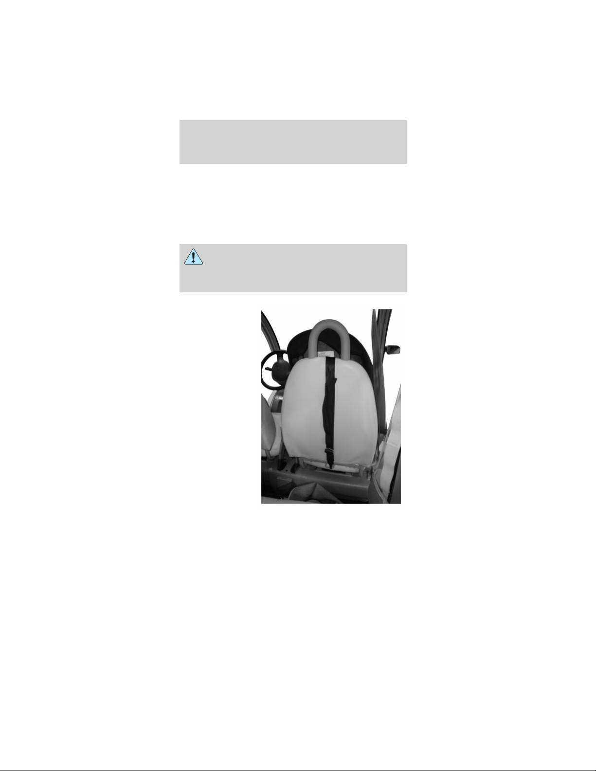
SWEATER NET (IF EQUIPPED)
The sweater net
drapes over the
front seat and is
held in place by
a locking clasp
that routes
around the
lower part of
the seat frame.
Place only soft, light-weight objects in the
net. Hard, heavy objects in the net could
cause injury in a collision.
Driver controls
32
TRUNK EXPANDER (IF EQUIPPED)
The trunk
expander is a
locking storage
area that is
inserted into
the trunk to
increase the
amount of
storage. The
trunk expander
is designed to
hold two paper
grocery bags in
the bottom with
three plastic
bags hung from hooks mounted inside the trunk
expander. There are two shelves to the right and left
of the main area to hold other items.
The hooks should not be loaded with over 8 lbs
(3.6 kg).
The trunk should not be loaded to over 200 lbs
(90.7 kg).
WEATHER ENCLOSURES (IF EQUIPPED)
The weather enclosures are designed to be installed
on the vehicle to help shield the vehicle users and
the interior of the vehicle from inclement weather.
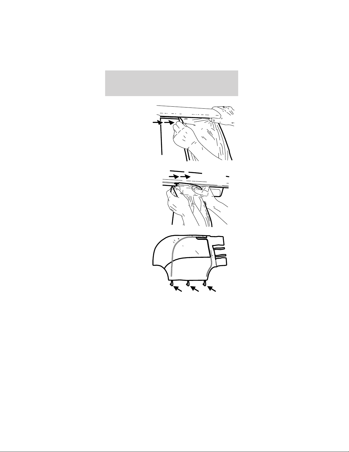
To install the weather enclosure:
Side panels:
Note: Opening the front access panel zipper can help
install the side panels.
1. Insert the side weather enclosure front hanger
(“T” section) into the slot on the underside of the
roof rail in front of the safety belt hanger bracket.
Driver controls
33
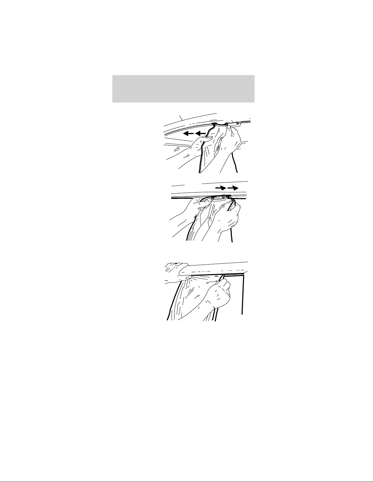
2. Slide the
hanger forward
until it reaches
the front
fender.
3. On
four-passenger
vehicles, insert
the side
weather
enclosure rear
hanger (“T”
section) into
the slot on the
underside of
the roof rail
behind the safety belt hanger bracket.
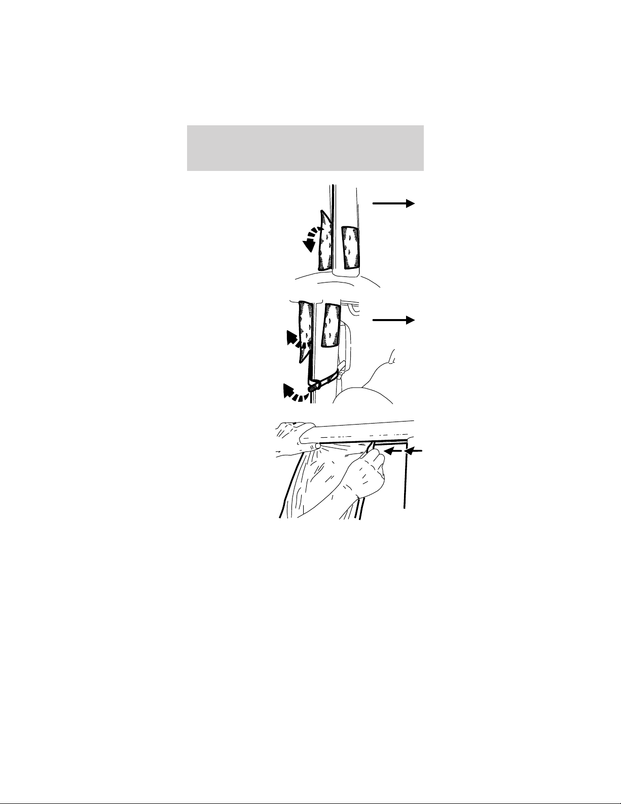
4. Slide the
hanger
rearward until it
reaches the
B-pillar.
Safety belt
hanger bracket
Roof rail
Driver controls
34
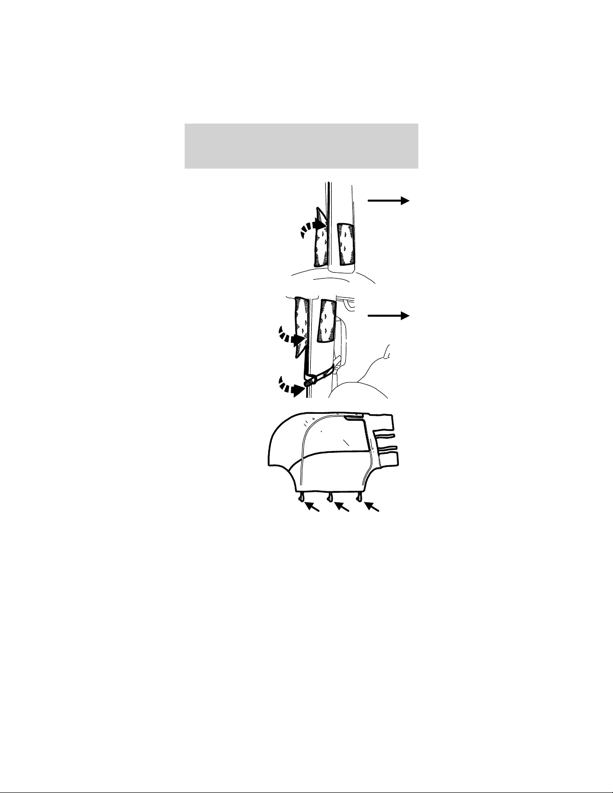
5. Wrap and
fasten the large
upper attaching
strap around
the B-pillar.
6. Wrap and
fasten the two
1-inch attaching
straps. Insert
the attaching
straps through
the D-ring and
fasten securely.
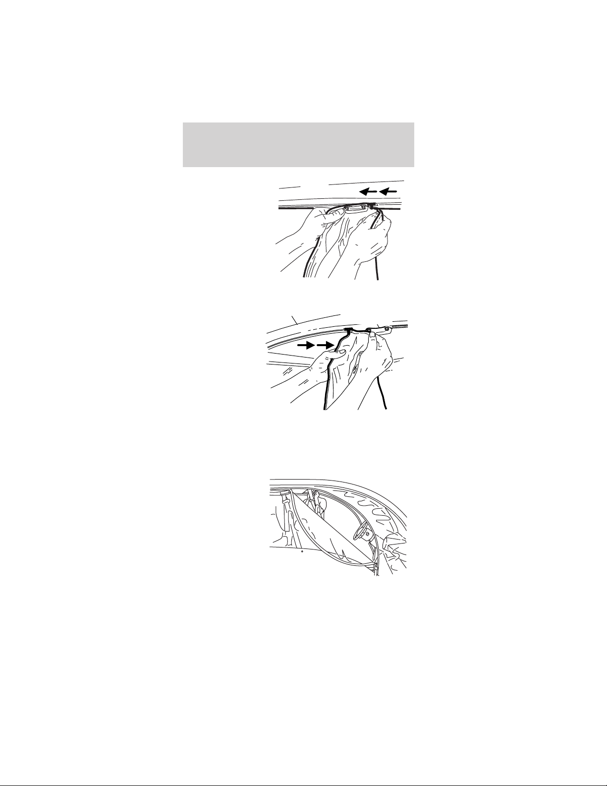
7. Attach the
three mounting
hooks to the
openings in the
frame rail.
8. Repeat steps 1- 7 for the opposite side of the
vehicle.
Front of
vehicle
Front of
vehicle
Driver controls
35
Rear panels:
9. Insert the
rear weather
enclosure
hanger into the
slot near the
high-mount stop
lamp.
10. Slide the
hanger toward
the B-pillar.
11. Zip the two
rear weather
enclosure to
side weather
enclosure
zippers.
Driver controls
36
12. Attach the
two rear
mounting hooks
to the rear
fenders.
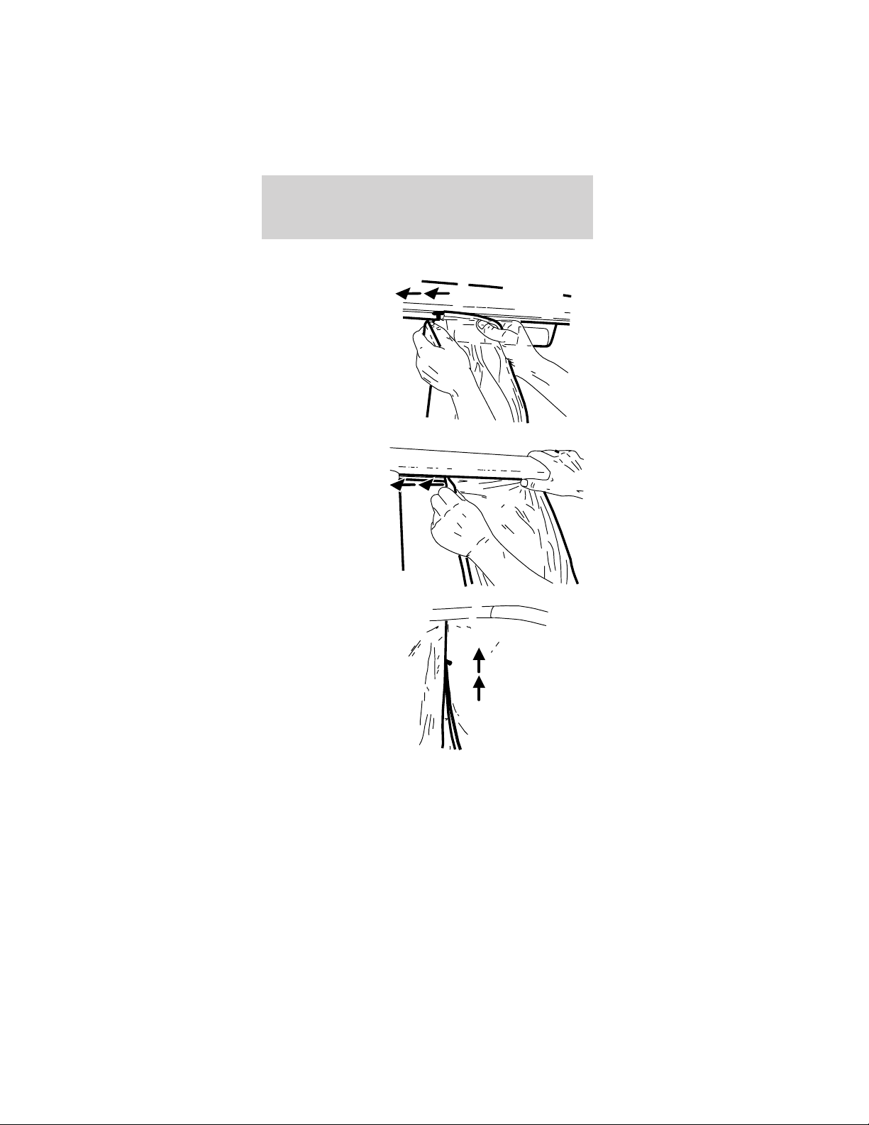
To remove the vehicle’s weather enclosure:
1. Unfasten the
two rear
mounting hooks
to the rear
fenders.
2. Unzip the
two rear
weather
enclosure to
side weather
enclosure
zippers
Driver controls
37
3. Slide the
hanger away
from the
B-pillar.
4. Remove the
rear weather
enclosure
hangers from
the slots behind
the high-mount
stop lamp.
5. Unfasten the
three side
weather
enclosure
mounting hooks
from the
openings in the
frame rail.
Driver controls
38
6. Pull apart the
large upper and
lower attaching
straps.
7. Pull apart the
two 1-inch
attaching
straps.
8. Slide the
hanger forward
away from the
B-pillar.
Front of
vehicle
Front of
vehicle
Driver controls
39
9. On
four-passenger
vehicles,
remove the side
weather
enclosure rear
hanger (“T”
section) from
the slot on the
underside roof
rail by the
safety belt hanger bracket.
10. Slide the
hanger away
from the front
fender.
11. Remove the side weather enclosure front hanger
from the slot on the underside of the roof rail in
front of the safety belt hanger bracket.
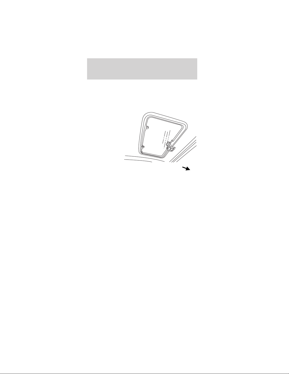
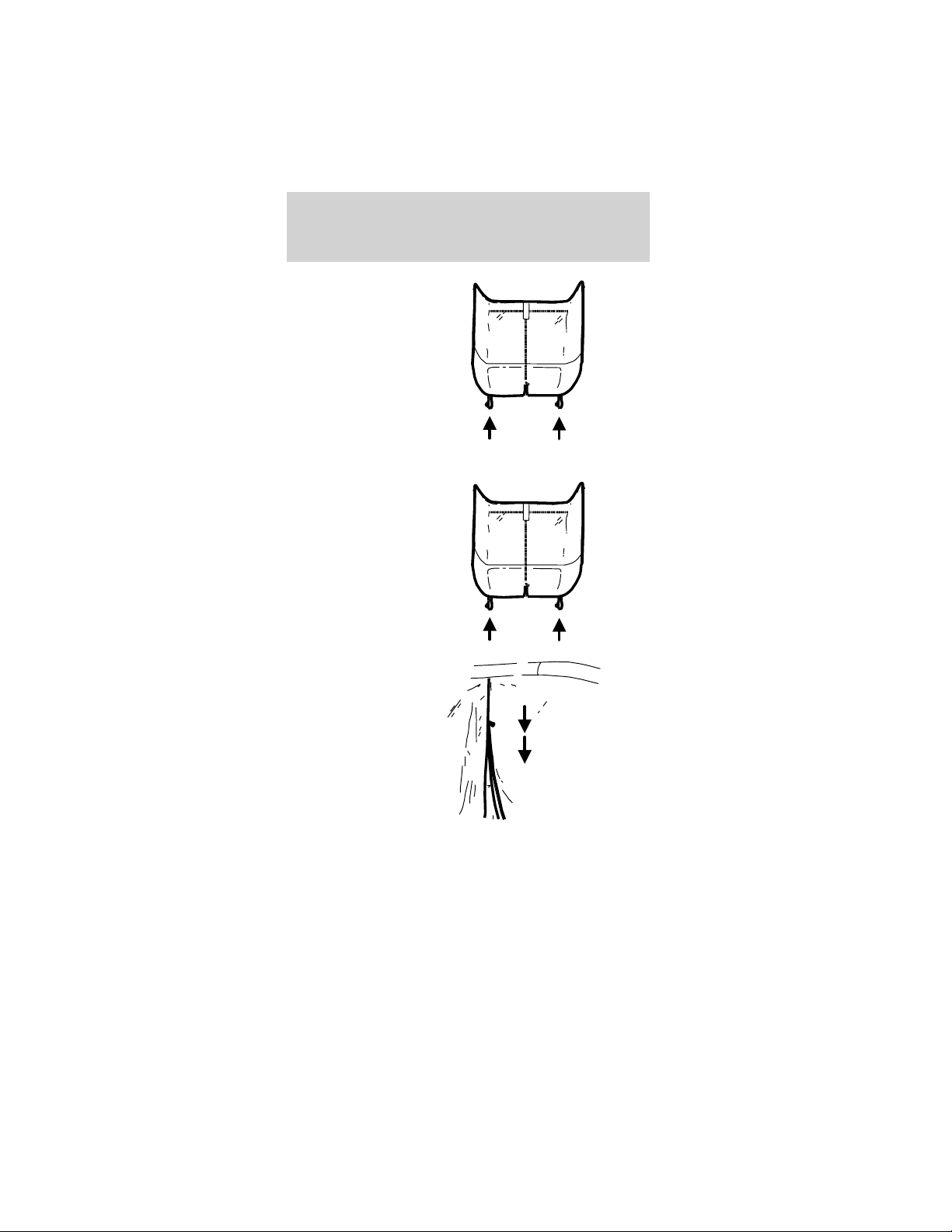
Ventilation and access
To open the
front “windows”
in the vehicle’s
weather
enclosure, refer
to the
illustration.
Roof rail
Safety belt
hanger bracket
Driver controls
40
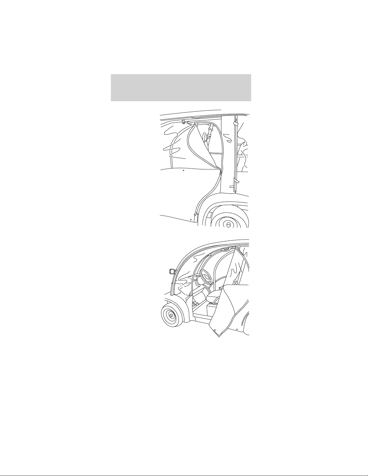
To open the
rear “windows”
on the
4-passenger
vehicle’s
weather
enclosure, refer
to the
illustration.
To open the
front access in
the vehicle’s
weather
enclosure, refer
to the
illustration.
Driver controls
41

To open the
front access on
the 4-passenger
vehicle’s
weather
enclosure, refer
to the
illustration.
Storage
After thoroughly cleaning and completely drying the
weather enclosures, you may store them in the
storage bag as follows:
1. Lay the weather enclosure panels flat on top of
each other on a clean, smooth surface.
2. Fold the bottom fabric onto the clear plastic.
3. From the front or rear, roll it up and slide it into
the storage bag.
Driver controls
42

VEHICLE COVER (IF EQUIPPED)
The vehicle cover drapes over the vehicle and is
held in place by elastic. It can be locked using a
cable and lock.
There are hydrogen gases around the
batteries that can explode if exposed to
flames, sparks, or lit cigarettes. The amount of
hydrogen gas is increased during battery charging.
An explosion could result in personal injury or
vehicle damage.
Do not charge the batteries with the
weather enclosure closed or the vehicle
cover in place. A build-up of hydrogen gas can
result which can cause an explosion. The charging
area should be well ventilated.
Driver controls
43
SEATING
Head restraints
The head restraints on the front and rear seats are
in a fixed position and cannot be adjusted or
removed.
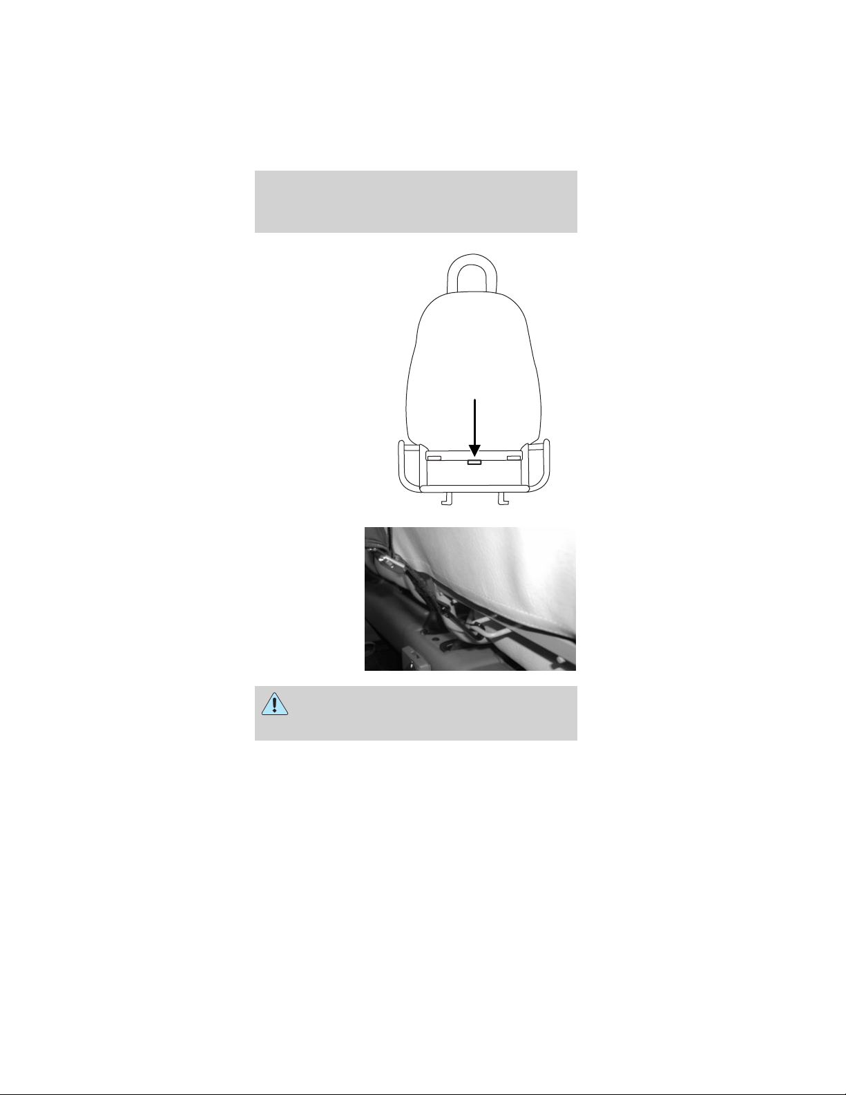
Front seat
Never adjust the driver’s seat when the
vehicle is moving.
Always make sure that both front seat
bottoms are latched down into place before
operating the vehicle.
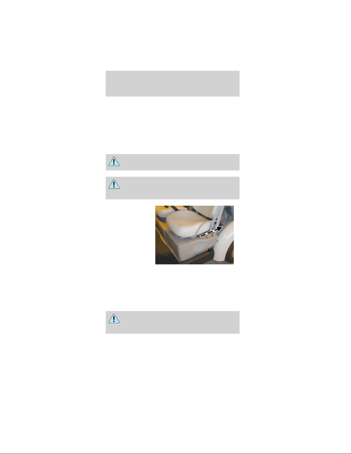
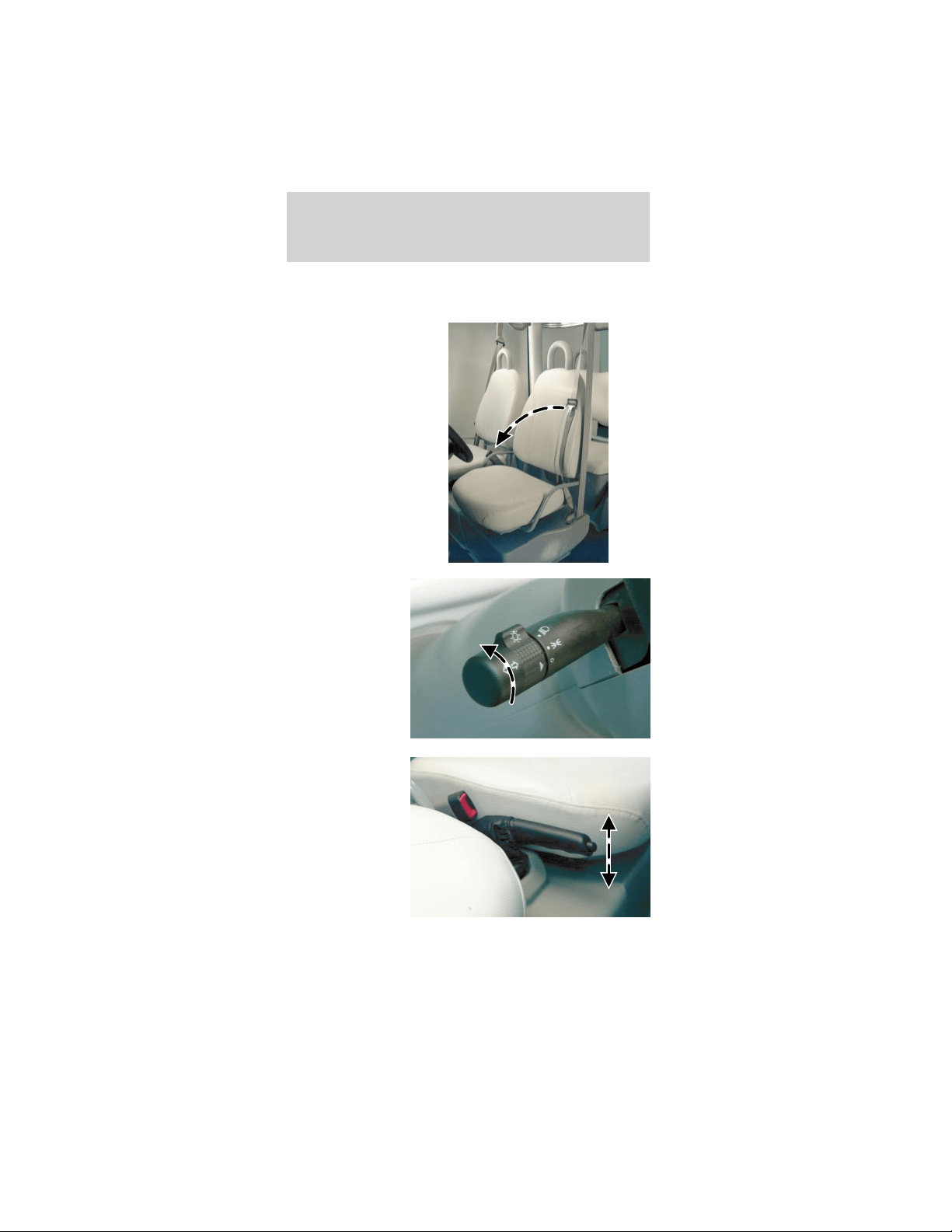
The driver’s
seat is on a
track and is
adjustable
forward and
back. To move
the seat
forward or
back, slide the
lever at the side
of the seat to
the rear and slide the seat to the desired position.
Release the lever to lock the seat in the new
position.
The front passenger seat is not adjustable.
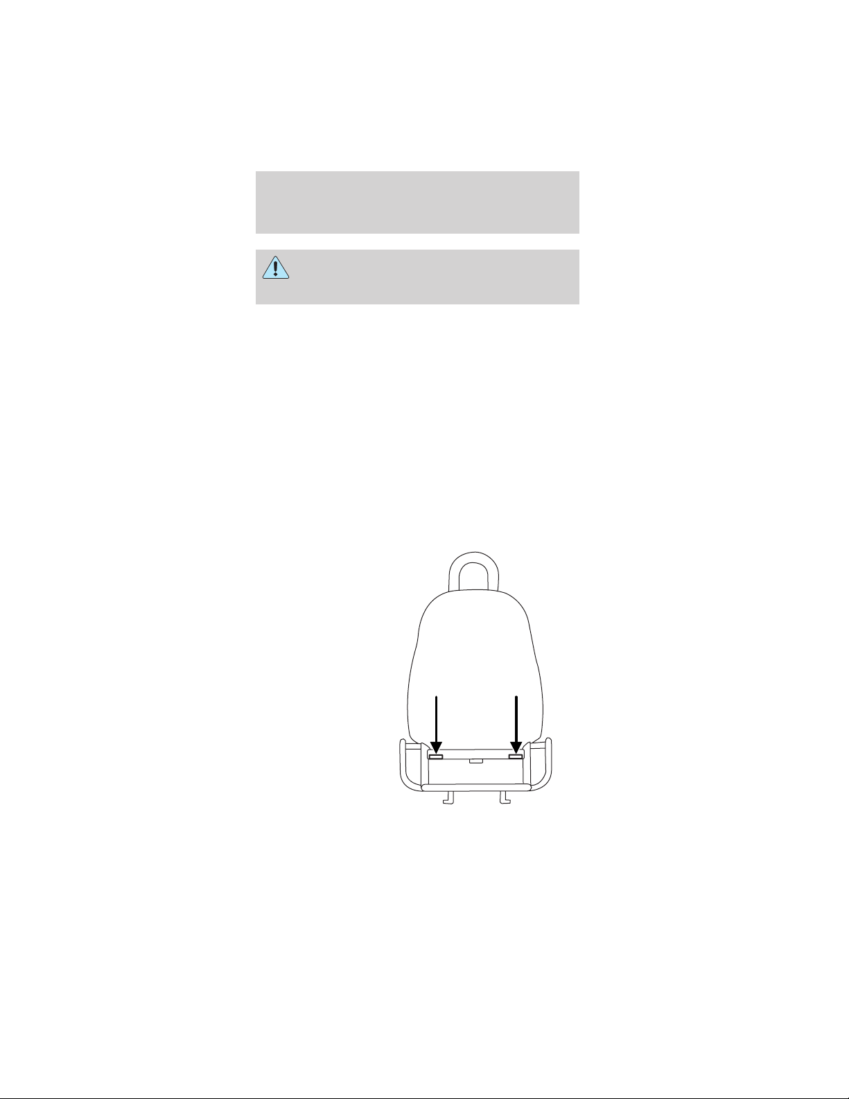
REAR SEATS (IF EQUIPPED)
Always make sure that the rear seat cushion
is locked down into place before operating
the vehicle.
The rear seat is not adjustable. The cushion lifts up
to access the rear seat storage compartment.
Seating and safety restraints
44
SAFETY RESTRAINTS
Safety restraints precautions
Always make sure that both front seat
bottoms are latched down into place before
operating the vehicle.
To reduce the risk of injury, make sure
children sit where they can be properly
restrained.
Never let a passenger hold a child on his or
her lap while the vehicle is moving. The
passenger cannot protect the child from injury in a
collision.
All occupants of the vehicle, including the
driver, should always properly wear their
safety belts.
It is extremely dangerous to ride in a cargo
area, inside or outside of a vehicle. In a
collision, people riding in these areas are more
likely to be seriously injured or killed. Do not allow
people to ride in any area of your vehicle that is
not equipped with seats and safety belts. Be sure
everyone in your vehicle is in a seat and using a
safety belt properly.
In a rollover crash, an unbelted person is
significantly more likely to die than a person
wearing a safety belt.
Seating and safety restraints
45
Each seating position in your vehicle has a
specific safety belt assembly which is made
up of one buckle and one tongue that are designed
to be used as a pair. 1) Use the shoulder belt on
the outside shoulder only. Never wear the shoulder
belt under the arm. 2) Never swing the safety belt
around your neck over the inside shoulder.
3) Never use a single belt for more than one
person.
Combination lap and shoulder belts
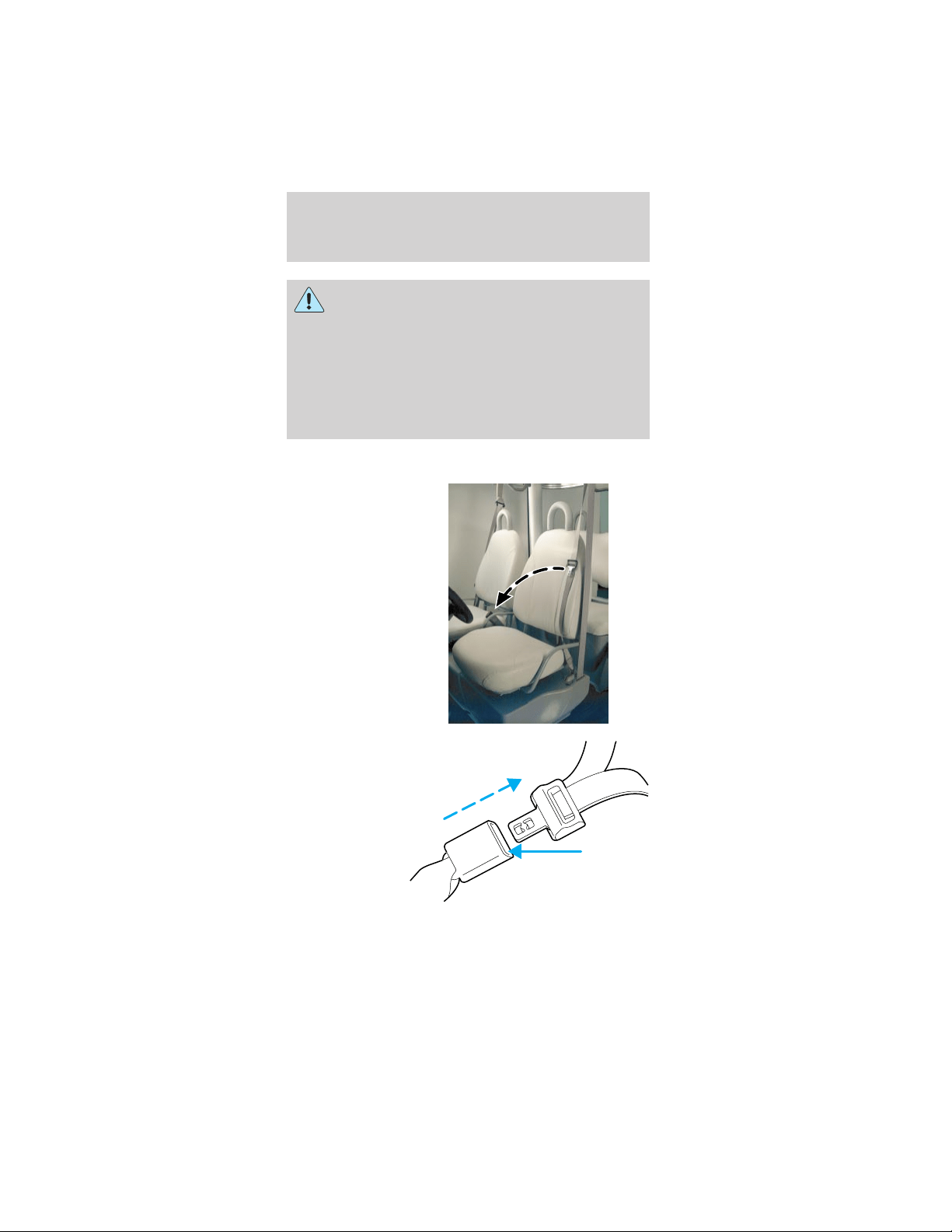
1. Insert the
belt tongue into
the proper
buckle (the
buckle closest
to the direction
the tongue is
coming from)
until you hear a
snap and feel it
latch. Make
sure the tongue
is securely
fastened in the
buckle.
2. To unfasten,
push the
release button
on the buckle
and pull the
tongue out of
the buckle.
Seating and safety restraints
46
Vehicle sensitive mode
The vehicle sensitive mode is the normal retractor
mode, allowing free shoulder belt length adjustment
to your movements, and locking in response to
vehicle movement. If the driver brakes suddenly or
turns a corner sharply, or the vehicle receives an
impact of approximately 8 km/h (5 mph) or more,
the combination safety belts will lock to help reduce
forward movement of the driver and passenger.
Cinch tongue mode
The front passengers and rear seat (if equipped)
have cinch tongues to help install a child safety seat
tightly.
The cinch tongue will slide up and down the belt
webbing when the belt is in the stowed position or
while putting safety belts on. When the cinch tongue
of the lap/shoulder combination safety belt is latched
into the buckle, the cinch tongue will allow the lap
portion to become shorter, but holds the webbing in
place to keep the lap belt from becoming longer.
Before you can reach and latch a combination lap
and shoulder belt having a cinch tongue into the
buckle, you may have to lengthen the lap belt
portion of it.
Seating and safety restraints
47

1. To lengthen
the lap belt,
pull some
webbing out of
the shoulder
belt retractor.
2. While holding
the webbing
below the
tongue, grasp
the tip (metal portion) of the tongue so that it is
parallel to the webbing and slide the tongue upward.
3. Provide enough lap belt length so that the tongue
can reach the buckle.
How to fasten the cinch tongue
1. Pull the combination lap and shoulder belt from
the retractor so that the shoulder belt portion of the
safety belt crosses your shoulder and chest.
2. Be sure the belt is not twisted. If the belt is
twisted, remove the twist.
3. Insert the belt tongue into the proper buckle for
your seating position until you hear a snap and feel
it latch.
4. Make sure the tongue is securely fastened to the
buckle by pulling on the tongue.
The lap belt should fit snugly and as low as
possible around the hips, not across the
waist.
Front and rear seat occupants, including
pregnant women, should wear safety belts
for optimum protection in an accident.
Seating and safety restraints
48

Each seating position in your vehicle has a
specific safety belt assembly which is made
up of one buckle and one tongue that are designed
to be used as a pair. 1) Use the shoulder belt on
the outside shoulder only. Never wear the shoulder
belt under the arm. 2) Never swing the safety belt
around your neck over the inside shoulder.
3) Never use a single belt for more than one
person.
While you are fastened in the safety belt, the
combination lap/shoulder belt with a cinch tongue
adjusts to your movement. However, if you brake
hard, turn hard, or if your vehicle receives an impact
of 8 km/h (5 mph) or more, the safety belt will lock
to help reduce your forward movement.
Safety belt extension assembly
If the safety belt is too short when fully extended,
there is a 20 cm (8 inch) safety belt extension
assembly.
Use only extensions manufactured by the same
supplier as the safety belt. Manufacturer
identification is located at the end of the webbing on
the label. Also, use the safety belt extension only if
the safety belt is too short when fully extended. Do
not use extensions to change the fit of the shoulder
belt across the torso.
Safety belt maintenance
Check the safety belt systems periodically to make
sure that they work properly and are not damaged.
All safety belt assemblies, including retractors,
buckles, child safety seat tether bracket assemblies
(if equipped), and attaching hardware, should be
inspected after any collision. Ford recommends that
all safety belt assemblies used in vehicles involved in
a collision be replaced. However, if the collision was
minor and a qualified technician finds that the belts
do not show damage and continue to operate
Seating and safety restraints
49

properly, they do not need to be replaced. Safety
belt assemblies not in use during a collision should
also be inspected and replaced if either damage or
improper operation is noted.
Failure to inspect and if necessary replace
the safety belt assembly following a collision
or in the event of a damaged or worn belt, could
result in severe personal injuries in the event of a
collision.
CHILD RESTRAINTS
Important precautions
You are required by law to use safety
restraints for children in the United States.
If small children ride in your vehicle (generally
children who are four years old or younger and
who weigh 18 kg [40 lbs] or less), you must put
them in safety seats made especially for children.
Check your local state laws for specific
requirements regarding the safe transportation of
children in your vehicle.
Never let a passenger hold a child on his or
her lap while the vehicle is moving. The
passenger cannot protect the child from injury in a
collision.
Always follow the instructions and warnings
that come with any infant or child restraint
you might use.
Seating and safety restraints
50

Children and safety belts
If the child is the proper size, restrain the child in a
safety seat.
Children who are too large for child safety seats (as
specified by your child safety seat manufacturer)
should always wear safety belts.
Moving the child closer to the center of the vehicle
may help provide a good shoulder belt fit.
To improve the fit of lap and shoulder belts on
children who have outgrown child safety seats,
TH!NK Mobility recommends use of a
belt-positioning booster seat that is labeled as
conforming to all applicable federal motor vehicle
safety standards. Belt—positioning booster seats
raise the child and provide a shorter, firmer seating
cushion that encourages safer seating posture and a
better fit of lap and shoulder belts.
A belt-positioning booster should be used if the
shoulder belt rests in front of the child’s face or
neck, or if the lap belt does not fit snugly on both
thighs, or if the thighs are too short to let the child
sit all the way back on the seat cushion when the
lower legs hang over the edge of the seat cushion.
You may wish to discuss the special needs of your
child with your pediatrician.
Follow all of the important safety restraint
precautions that apply to adult passengers in your
vehicle.
Do not leave children, unreliable adults, or
pets unattended in your vehicle.
Seating and safety restraints
51
SAFETY SEATS FOR CHILDREN
Child and infant or child safety seats
Use a safety seat that is recommended for the size
and weight of the child. Carefully follow all of the
manufacturer’s instructions with the safety seat you
put in your vehicle. If you do not install and use the
safety seat properly, the child may be injured in a
sudden stop or collision.
When installing a child safety seat:
• Use the correct safety belt buckle for that seating
position.
• Insert the belt tongue into the proper buckle until
you hear a snap and feel it latch. Make sure the
tongue is securely fastened in the buckle.
• Keep the buckle release button pointing up and
away from the safety seat, with the tongue
between the child seat and the release button, to
prevent accidental unbuckling.
• Place seatback in upright position.
Carefully follow all of the manufacturer’s
instructions included with the safety seat
you put in your vehicle. If you do not install and
use the safety seat properly, the child may be
injured in a sudden stop or collision.
Seating and safety restraints
52
Installing child safety seats in cinch tongue
combination lap and shoulder belt seating
positions (typical seat shown)
The belt webbing below the tongue is the lap
portion of the combination lap/shoulder belt, and the
belt webbing above the tongue is the shoulder belt
portion of the combination lap/shoulder belt.
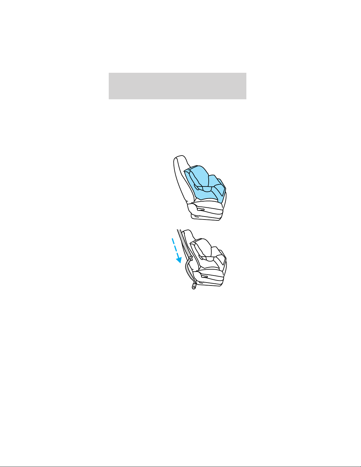
1. Position the
child safety seat
in a seat with a
combination lap
and shoulder
belt.
2. Grasp the
belt webbing
below the
tongue and pull
as much of the
belt out of the
retractor as
possible. Hold
the belt out.
Seating and safety restraints
53
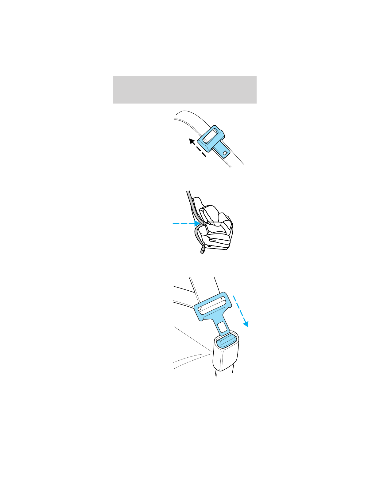
3. With your
other hand,
grasp the tip
(metal portion)
of the tongue
(not the cover)
and slide the
tongue up the
webbing as far
as it will go.
Release the tongue, but do not let go of the lap
portion of the belt webbing.
4. While holding
the shoulder
and lap portions
together, route
the tongue and
webbing
through the
child seat
according to the
child seat
manufacturer’s
instructions. Be sure that the belt webbing is not
twisted.
5. Insert the
belt tongue into
the proper
buckle for that
seating position
until you hear a
snap and feel it
latch. Make
sure the tongue
is securely
latched to the
buckle by
pulling on the
tongue.
Seating and safety restraints
54
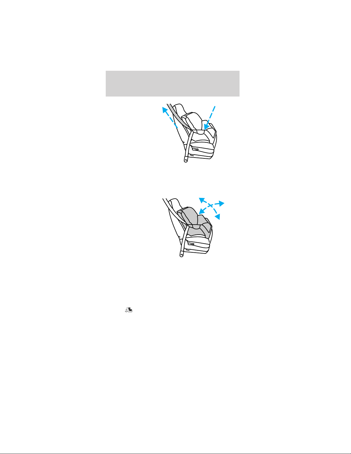
6. While
pushing down
with your knee
on the child
seat, pull up on
the shoulder
belt portion to
tighten the lap
belt portion of
the combination
lap and
shoulder belt.
7. Allow the safety belt to retract and remove any
slack in the belt to securely tighten the child safety
seat in the vehicle.
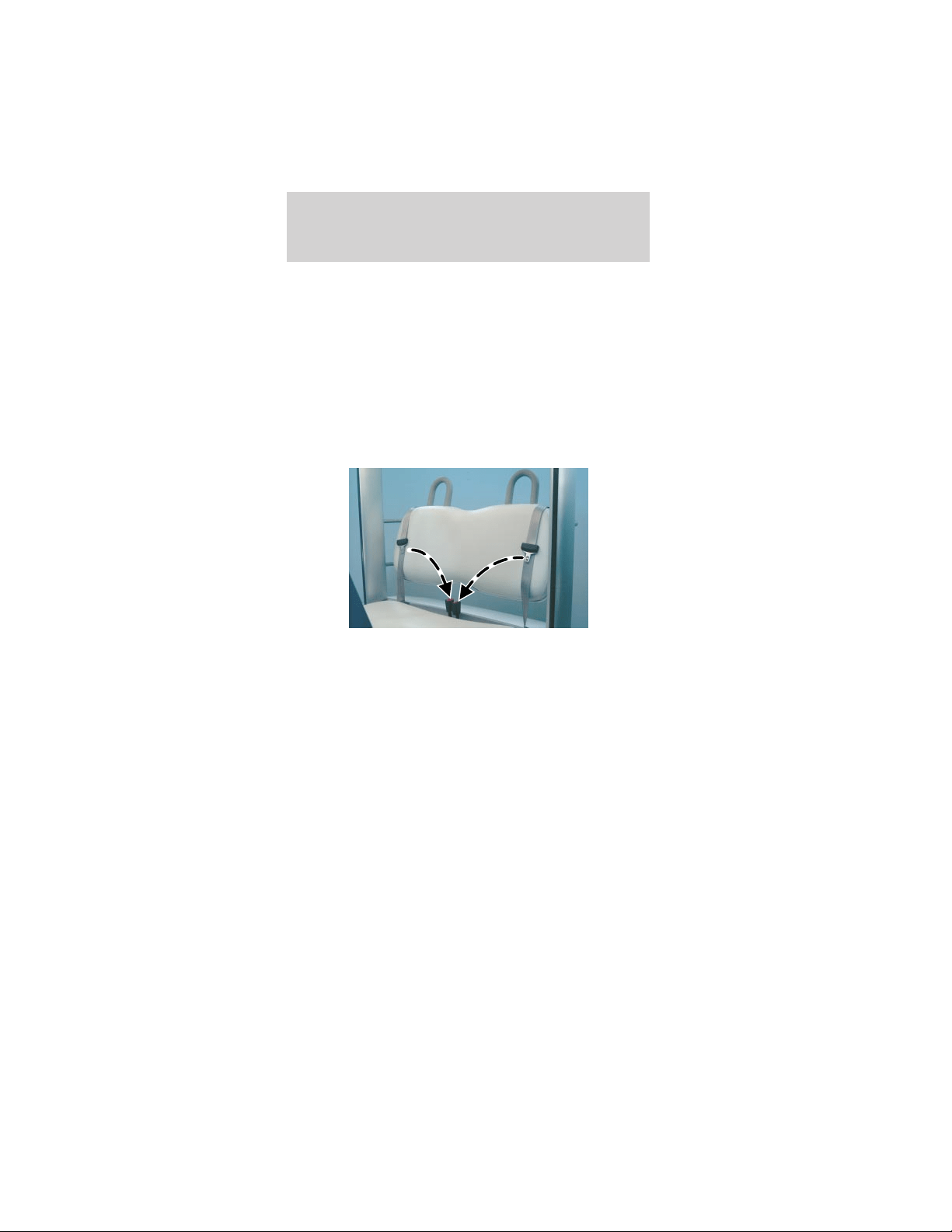
8. Before
placing the
child into the
child seat,
forcibly tilt the
child seat
forward and
back to make
sure that the
seat is held
securely in
place.
9. Check from time to time to be sure that there is
no slack in the lap/shoulder belt. The shoulder belt
must be snug to keep the lap belt tight during a
collision.
Attaching child safety seats with tether
straps
Most new forward-facing child safety seats include a
tether strap which goes over the back of the seat
and hooks to an anchoring point. Tether straps are
available as an accessory for many older safety seats.
Contact the manufacturer of your child seat for
information about ordering a tether strap.
Seating and safety restraints
55
The optional LATCH equipped passenger seat is
equipped with built-in tether strap anchors located
behind the seat as described below.
The tether anchor (if equipped) in your vehicle is
located at the bottom of the front passenger
seatback.
Attach the tether strap only to the
appropriate tether anchor as shown. The
tether strap may not work properly if attached
somewhere other than the correct tether anchor.
1. Position the
child safety seat
on the seat
cushion.
2. Route the
child safety seat
tether strap
over the back of
the seat and
between the
head restraint
posts.
Seating and safety restraints
56
3. Locate the
correct anchor.
4. Clip the
tether strap to
the anchor as
shown.
If the tether strap is clipped incorrectly, the
child safety seat may not be retained
properly in the event of a collision.
5. Refer to the Installing child safety seats in
combination lap and shoulder belt seating
positions section of this chapter for further
instructions to secure the child safety seat.
6. Tighten the child safety seat tether strap
according to the manufacturer’s instructions.
Seating and safety restraints
57
If the safety seat is not anchored properly,
the risk of a child being injured in a collision
greatly increases.
Attaching safety seats with LATCH
(Lower Anchors and Tethers for Children)
attachments for child seat anchors
Some child safety seats have two rigid or webbing
mounted attachments that connect to two anchors
at a certain seating position in your vehicle. This
type of child seat eliminates the need to use safety
belts to attach the child seat. For forward-facing
child seats, the tether strap must also be attached to
the proper tether anchor. See Attaching safety seats
with tether straps in this chapter.
Your vehicle has LATCH anchors for child seat
installation at the optional LATCH equipped front
passenger seat.
The lower
anchors for
child seat
installation are
located at the
rear section of
the optional
LATCH
equipped front
passenger seat
between the
cushion and
seat back.
Seating and safety restraints
58

Follow the child seat manufacturer’s instructions to
properly install a child seat with LATCH
attachments. Two plastic LATCH guides can be
obtained at no charge from any TH!NK dealer. They
snap onto the LATCH lower anchors in the seat to
help attach a child seat with rigid attachments. The
guides hold the seat trim away to expose the anchor
and make it easier to attach some child seats.
Attach LATCH lower attachments of the
child seat only to the anchors shown.
If you install a child seat with rigid LATCH
attachments, do not tighten the tether strap enough
to lift the child seat off the vehicle seat cushion
when the child is seated in it. Keep the tether strap
just snug without lifting the front of the child seat.
Keeping the child seat just touching the vehicle seat
gives the best protection in a severe crash.
Each time you use the safety seat, check that the
seat is properly attached to the lower anchors and
tether anchor. Try to tilt the child seat from side to
side. Also try to tug the seat forward. Check to see
if the anchors hold the seat in place.
If the safety seat is not anchored properly,
the risk of a child being injured in a crash
greatly increases.
Seating and safety restraints
59
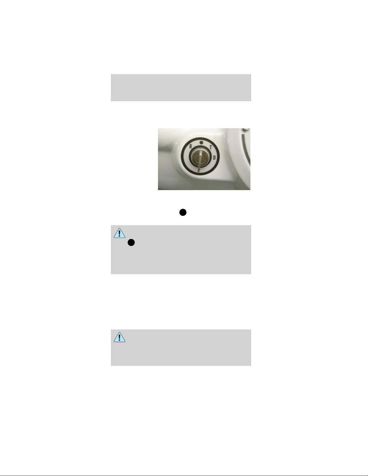
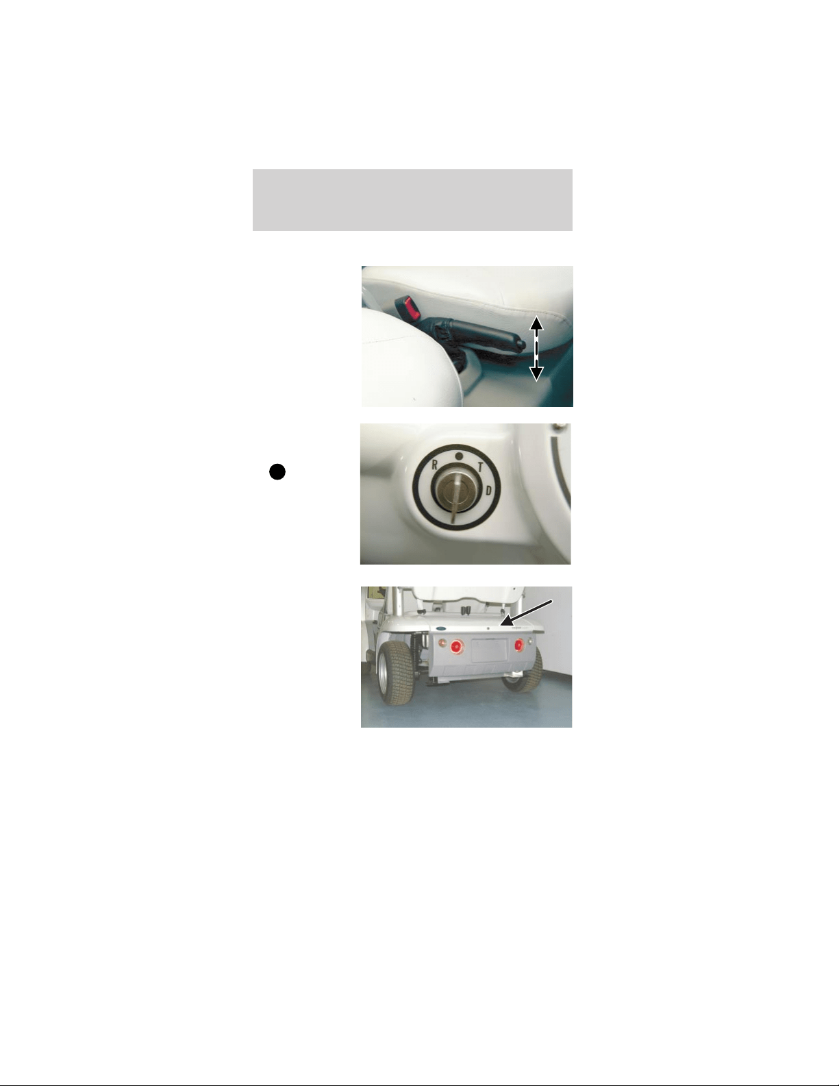
STARTING
Operating positions
The drive mode
selector switch
serves two
functions. It
powers up the
electric motor
by activating
the battery
pack to connect
the power to
the drivetrain
system. It also functions as a gear selector by
placing the drive mode selector switch key in one of
four modes: R (Reverse),
(OFF), T (Turf), and
D (Drive).
Never press the accelerator while turning
the drive mode selector switch key
from
(OFF) to one of the driving modes.
Always firmly apply the brake pedal until ready to
drive the vehicle in the selected mode. In addition,
follow the safety steps in Important safety
precautions in this chapter.
1. R (Reverse mode)
The R (Reverse) mode is used to maneuver your
vehicle out of parking spots or rough terrain
where you cannot proceed forward. A reverse
warning will sound to alarm the driver that the
vehicle will be backing up. The maximum speed in
R (Reverse) is 13 km/h (8 mph).
Extra care should be used to visually check
behind the vehicle before engaging R
(Reverse) mode. Do not rely on your mirrors alone
as there may be blind spots, depending on how
you have the mirrors adjusted.
Driving
60

2. (OFF)
The
(OFF) position for the drive mode
selector switch key will power down the drivetrain
system as well as the other vehicle systems. The
parking brake should always be engaged when the
key is in this position.
3. T (Turf) mode
The T (Turf) mode is used when you are driving
on grass, sand, dirt, gravel, or pathways with loose
surfaces to provide safe handling characteristics of
your vehicle. The maximum speed in T (Turf)
mode is 24 km/h (15 mph).
4. D (Drive) mode
The D (Drive) mode will provide maximum
performance from your vehicle on the paved paths
and paved roadways. Your vehicle’s maximum
speed is 25 mph (40 km/h) and you should only
operate your vehicle on roadways with a
maximum speed of 56 km/h (35 mph) or less.
Park brake reminder
The park brake reminder is a tone that sounds for
10 seconds when the drive mode selector switch is
turned to the OFF position with the parking brake
not set. It will cease to sound after 10 seconds or
when the parking brake is engaged. During this time
the vehicle is “alive” with functional park brake
reminder and the gauge will be active and backlit.
After 10 seconds, the vehicle shuts down and the
park brake reminder is no longer functional.
To avoid serious injury, death, and/or
property damage, always engage the parking
brake before leaving the vehicle.
Driving
61
Important safety precautions
Before operating the vehicle:
1. Make sure all
vehicle
occupants have
buckled their
safety belt. For
more
information on
safety belts and
their proper
usage, refer to
Seating and
safety
restraints.
2. Make sure all
accessories,
such as
headlamps, are
turned off.
3. Make sure
the parking
brake is set.
Driving
62
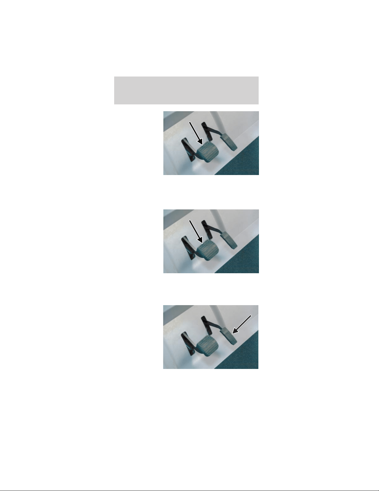
4. Do not press
the accelerator
while turning
the drive mode
selector key.
Always firmly
apply the brake
pedal until you
are ready to
drive the
vehicle in the
selected mode.
To operate the vehicle:
1. Insert the key in the drive mode selector switch.
2. Depress the
brake pedal.
3. Turn the drive mode selector key to the desired
operating mode.
4. Release the brake pedal.
5. Gradually
depress the
accelerator
pedal.
Driving
63
When parking the vehicle and turning it off:
1. Make sure
the parking
brake is set.
2. Turn the
drive mode
selector switch
to
(OFF)
and remove the
key from the
mode select
switch to
prevent
unauthorized
use.
3. Store any
items in the
locking glove
box and locking
rear storage
compartment.
4. Whenever possible, recharge your vehicle
batteries to maximize your range.
Battery charging
Battery charging uses 110 volt AC 15A service. The
GFCI (ground fault circuit interrupt) charge cord
plugs directly into the charge inlet located below
Driving
64

and to the left of the steering wheel. Approximately
8-10 hours are needed to replenish an 80% (four
bars showing) discharged battery pack. Charge the
vehicle whenever the state of charge is less than
80% (One bar showing) to maximize your travel
range.
The battery charger receives 110 volt AC 15A power
from an external standard grounded 3-prong outlet
and converts it to DC energy. The battery charger
only operates when a GFCI charger cord is plugged
into your vehicle. If the battery charger detects any
presence of AC current, your vehicle cannot be
started or driven.
Caution: If you allow your vehicle to sit in
conditions of -6°C (20°F) or less with a charge
of 20% ( two bars showing on gauge) or less,
the batteries could freeze. Allowing the
batteries to freeze may cause permanent
damage to the batteries and permanently
reduce their capacity. In cold conditions, place
the vehicle in an area greater than 0°C (32°F)
and allow it to warm up before charging. Never
charge the vehicle if the batteries may be
frozen. Allow the batteries to warm above 0°C
(32°F) first, then charge.
There are gases around the batteries that
can explode if exposed to flames, sparks, or
lit cigarettes. The amount of gas is increased
during battery charging. An explosion could result
in personal injury or vehicle damage.
Do not charge the batteries with the
weather enclosure closed or the vehicle
cover in place. A build up of hydrogen gas can
result which can explode. The charging area
should be well ventilated.
Driving
65
To recharge your vehicle batteries:
1. Park your vehicle within GFCI charger cord length
of a 110 volt AC 15A grounded 3-prong wall outlet.
2. Place the drive mode selector switch in the OFF
position, remove the key and set the parking brake.
Note: Make sure the power point (if equipped) is
not in use.
Note: Make sure that the inlet is clean and dry.
Note: Never use a plug adapter or an extension
cord.
3. Insert the male end of the GFCI charger cord in a
120 VAC grounded receptacle. Verify that the power
indicator light on the GFCI is on.
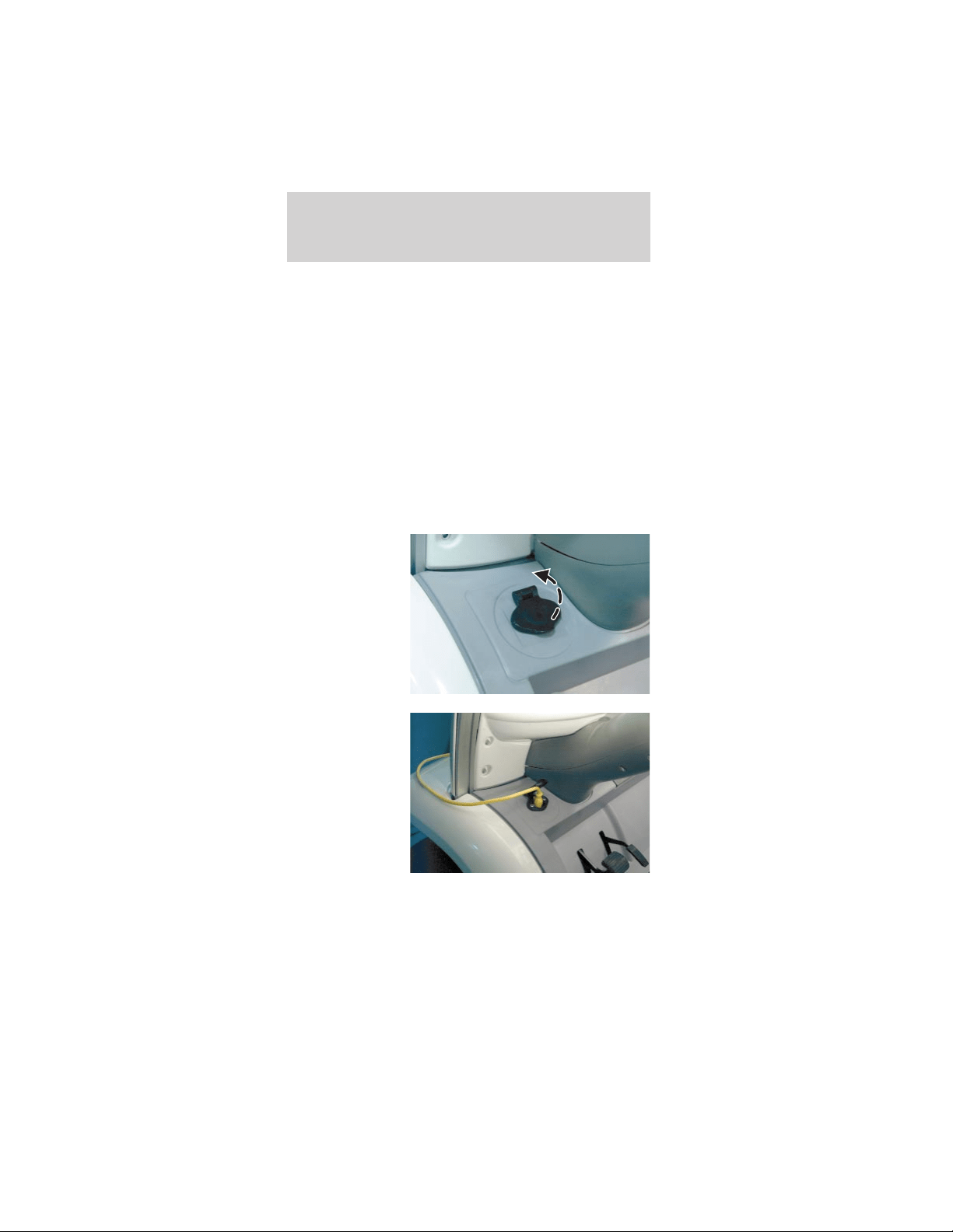
4. Open the
charge inlet
access door.
5. Align the
GFCI charger
cord with the
charge inlet and
fully insert the
plug into the
outlet.
6. Verify that the battery charge indicator on the
instrument cluster is illuminated during the charging
process.
Driving
66
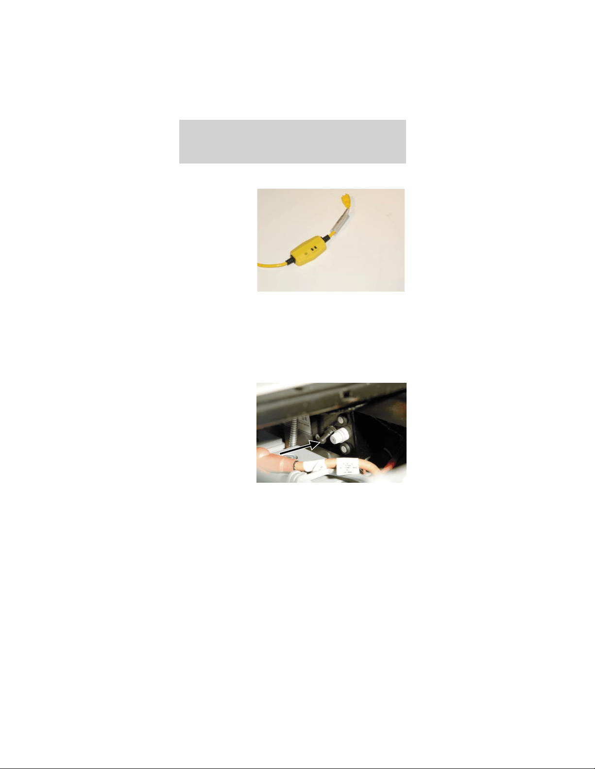
To stop charging of your vehicle batteries:
1. Push the
TEST button on
your GFCI
charger cord.
Verify that the
indicator light
on the GFCI is
OFF.
2. Disconnect the GFCI charger cord from the wall
outlet.
3. Disconnect the GFCI charger cord from the
charge inlet.
4. Store the cord in a safe and dry location.
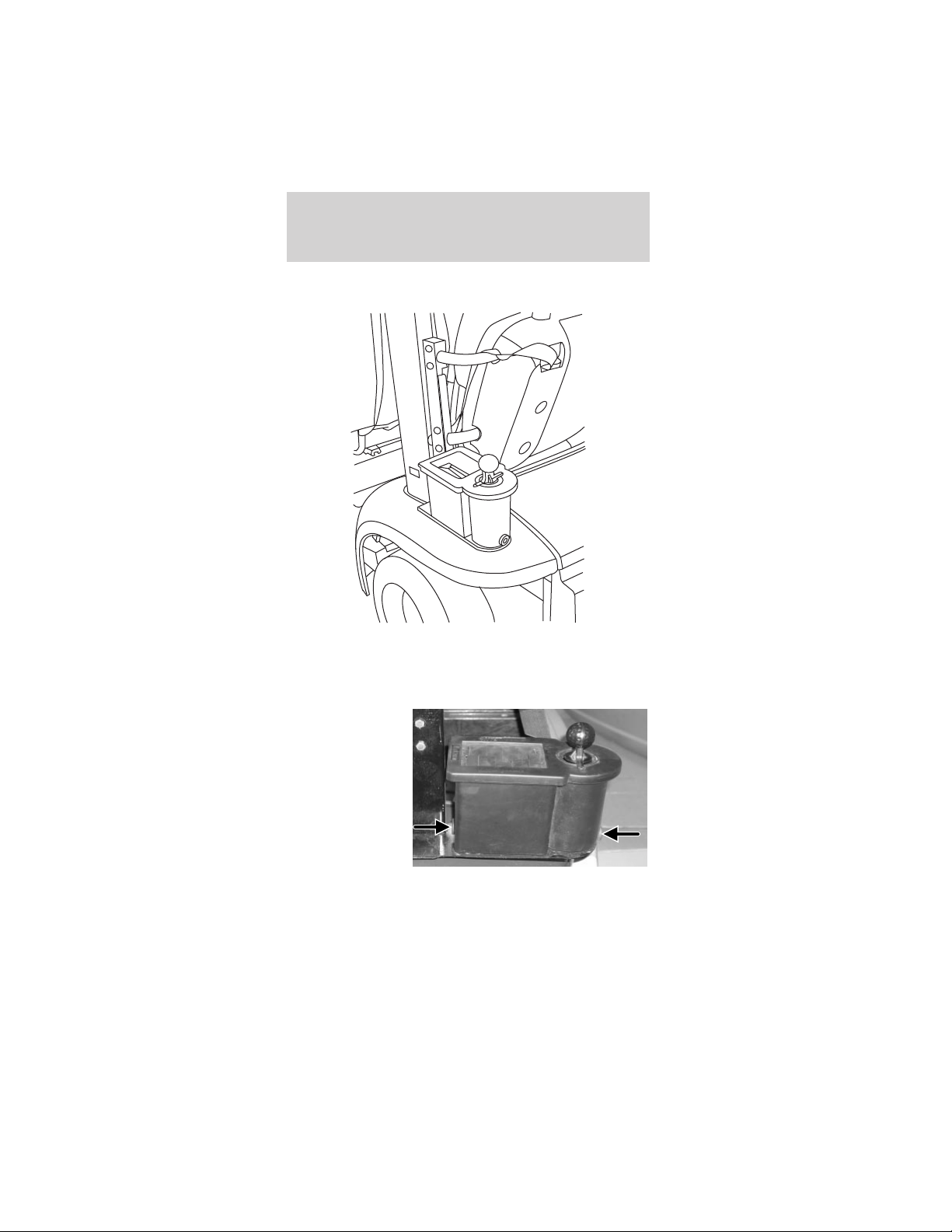
Battery charging during vehicle storage
The seat
stanchion front
cover should be
removed to
access the
service
disconnect
switch. The
service
disconnect
switch is
located below and behind the parking brake lever
within the seat stanchion (battery cover). It is a
black rubber switch and faces the front of the the
vehicle. It is not encouraged to blindly reach down
through the driver’s side opening on top of the seat
stanchion cover when the cushion is removed.
The vehicle can be stored for 21 days with the
service disconnect switch on. This assumes a full
charge when stored. If this time is exceeded or the
batteries were not fully charged prior to storing the
Driving
67
vehicle, the batteries may be severely discharged
resulting in permanent damage. This will reduce the
batteries capacity and vehicle range.
The vehicle can be stored with the service
disconnect switch off for six months if starting with
a full charge. With the service disconnect switch in
the OFF position, there is no current draw from the
vehicle components. The battery self-discharge
determines the storage time. This is less than 5%
per month at temperatures between 4°C and 21°C
(40°F and 70°F). Self-discharge increases slightly at
higher temperatures. If the batteries are nearly
discharged, they may freeze at 0°C (32°F) or below.
This will cause severe damage that may even cause
leakage of the electrolyte.
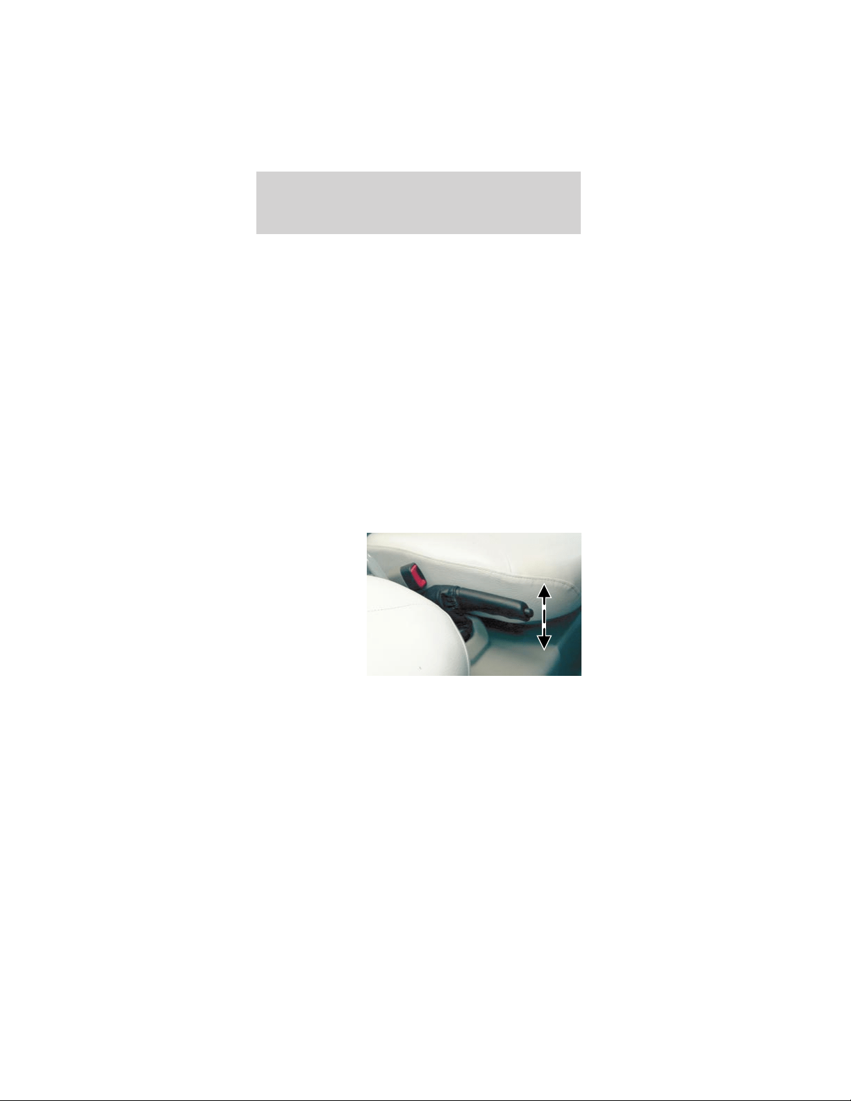
BRAKES
Parking brake
Apply the
parking brake
whenever the
vehicle is
parked or left
unattended. To
set the parking
brake, pull up
on the lever
between the
front seats as
far as it will go. The brake status indicator will be
illuminated whenever the parking brake is engaged
and the drive mode selector switch is turned to one
of the run modes.
To release the parking brake, pull up on the handle,
push the button in on the end of the handle, and
lower the handle to the horizontal position. The
brake status indicator will turn off when the parking
brake is fully released and the drive mode selector
switch is turned to one of the run modes.
Driving
68

The parking brake is not recommended to stop a
moving vehicle. However if the normal brakes fail,
the parking brake can be used to stop the vehicle in
an emergency situation. Since the parking brake only
applies the rear brakes, the vehicle’s stopping
distance will greatly increase.
Park brake reminder
The park brake reminder is a tone that sounds for
ten seconds when the drive mode selector switch is
turned to the OFF position with the parking brake
not set. It will cease to sound after ten seconds or
when the parking brake is engaged.
During this time the vehicle is “alive” with functional
park brake reminder and the gauge will be active and
backlit. After the ten seconds the vehicle shuts down
and park brake reminder is no longer functional.
To avoid serious injury, death, and/or
property damage, always engage the parking
brake before leaving the vehicle.
Dual circuit braking system
The hydraulic brake system is a dual circuit design.
This means if you have a brake system fluid leak or
failure, half of your brake system may remain
operational; the system will stop your vehicle, but
your stopping distance will be greatly increased.
Regenerative Braking System (RBS)
Another feature of your vehicle is the Regenerative
Braking System (RBS). The RBS is designed to
utilize the vehicle’s forward motion to generate
electricity and partially recharge the batteries for a
nominal increase in driving range. The RBS works
when you are not applying the accelerator. As your
vehicle coasts, it will use the electric motor as a
generator, producing a small amount of electricity
which will partially recharge the batteries. The RBS
works only when the vehicle is traveling at 29 km/h
(18 mph) or greater and the batteries are less than
80% charged to capacity.
Driving
69
HAZARD FLASHER SWITCH
Use the hazard
flashers only in
an emergency
to warn traffic
of your vehicle
breakdown, or
approaching
danger, etc. The
hazard flashers
can be operated
with the drive
mode selector switch in all positions. The hazard
flasher switch is located on top of the steering
column, right behind the steering wheel. Depress the
switch to activate the hazard lights. To turn off the
hazard lights, depress the switch again.
With the hazard flasher
switch depressed, both
turn signal indicators
will flash on the instrument panel cluster.
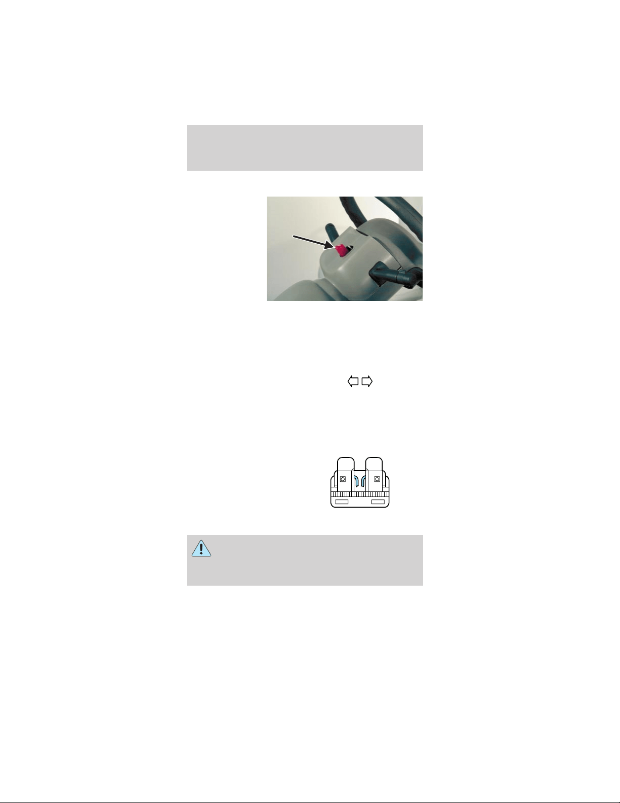
12V FUSES
Change a fuse
If electrical components
are not working, check
the circuit fuse first to
see if it is blown. You
can identify a blown
fuse by the broken wire
in the center of the fuse between two prongs.
Always replace a fuse with one that has the
specified amperage rating. Using a fuse with
a higher amperage rating can cause severe wire
damage and could start a fire.
15
Roadside emergencies
70
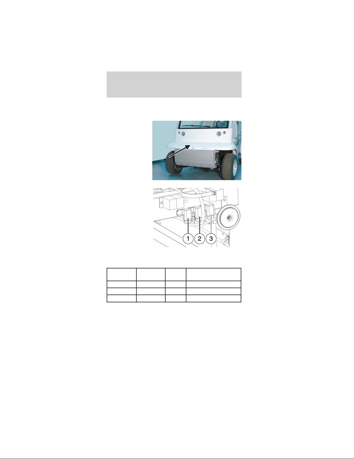
Central fuses
To access the fuses:
1. Unlock and
remove the
hood.
2. Inspect the
fuse for the
circuit with a
malfunction and
replace the fuse
if necessary.
Always use the
same amperage
rated fuse as a
replacement.
See the chart
for the fuse amperage ratings and circuit
descriptions.
Fuse
Location
Fuse Amp
Rating
Fuse
color
Circuit description
1 20A Blue Horn, Flasher, Brake
2 20A Blue Lights
3 10A Red Wiper, Washer, Gauge
3. After replacing the fuse, check the component to
verify that it is operating properly.
4. Install and lock the hood.
Roadside emergencies
71
Power point fuse (if equipped)
The power
point (if
equipped)
requires a 20A
fuse.
CHANGING THE TIRES
Your vehicle is not equipped with a spare tire.
Should your tires require service take you vehicle to
an authorized Dealer.
Jacking
Lifting instructions
Damage to the suspension or steering linkage
system components may occur when
positioning the jack pad. The pad should be
positioned carefully to ensure maximum
contact under the frame.
When lifting a vehicle, care should be taken to
position the vehicle so that the jack pads do
not damage the halfshafts, steering linkage or
suspension arms. Damage to suspension and/or
steering linkage components may occur.
To lessen risk of personal injury, do not put
any part of your body under the vehicle while
jacking.
Roadside emergencies
72
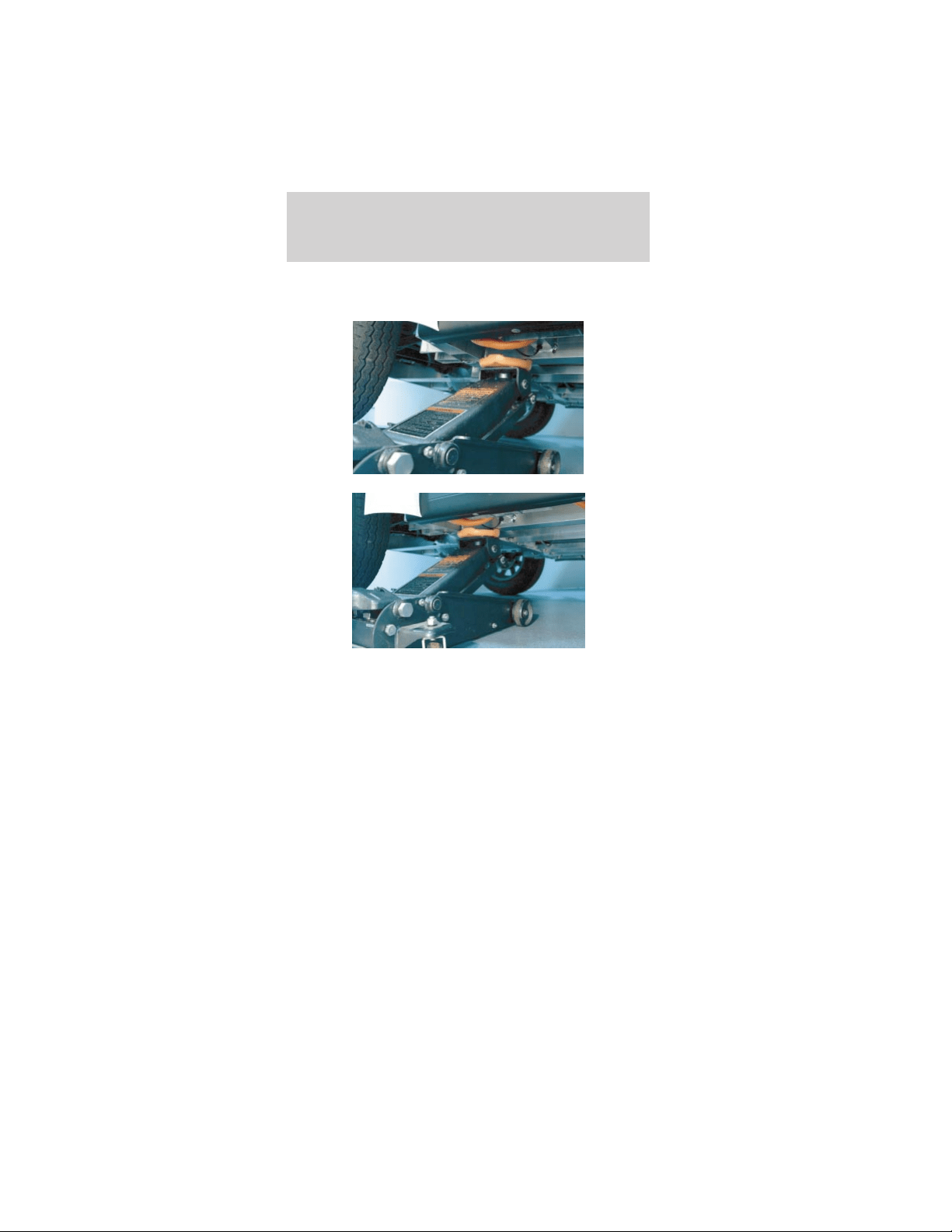
Your vehicle is constructed with many aluminum
components which may be damaged if:
• The proper jack lifting points are not utilized.
Roadside emergencies
73
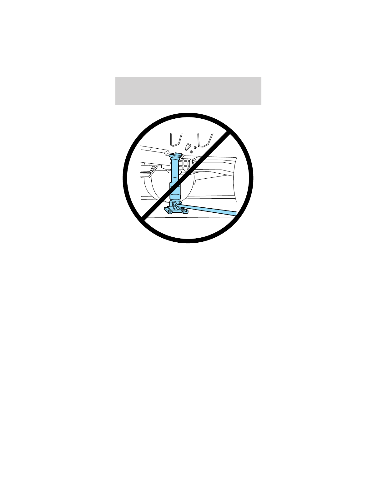
• A bottle type jack is used for ANY lifting of the
vehicle.
• The jack is not secured on a level and solid
surface.
WRECKER TOWING
If you need to have your vehicle towed, contact a
professional towing service or, if you are a member,
your roadside assistance center.
It is recommended that your vehicle be towed with
flatbed equipment. Do not tow with a slingbelt.
TH!NK Mobility has not approved a slingbelt towing
procedure.
It is not acceptable to tow the vehicle with the front
wheels on the ground (without dollies) and the rear
wheels off the ground.
If the vehicle is towed by other means or
incorrectly, vehicle damage may occur.
Roadside emergencies
74
If your vehicle
must be towed
using another
low speed
vehicle, for
example in the
event the
batteries are
discharged, the
service
disconnect
switch should be switched to the OFF position.
The seat stanchion front cover should be removed to
access the service disconnect switch. The service
disconnect switch is located below and behind the
parking brake lever within the seat stanchion
(battery cover). It is a black rubber switch and faces
the front of the the vehicle. It is not encouraged to
blindly reach down through the driver’s side opening
on top of the seat stanchion cover when the cushion
is removed. It is not encouraged to blindly reach
down through the driver’s side opening on top of the
seat stanchion cover when the cushion is removed.
Each corner of
your vehicle is
equipped with a
tow/tie down
hook. Both
front or both
rear tow hooks
must be used
for towing or
recovery
operations.
Additionally, when shipping or transporting, all four
tow/tie down hooks must be used to prevent
damage.
Roadside emergencies
75

WASHING YOUR VEHICLE
Do not take your vehicle to an automatic car
wash or use a high power spray hose to wash
your vehicle.
Wash your vehicle regularly with cold or lukewarm
water. Never use strong detergents or soaps. Always
use a clean sponge and plenty of water to avoid
scratching the dirt into your vehicle’s finish. To avoid
spotting, do not wash your vehicle in direct sunlight.
Any chemicals or foreign material such as tar, tree
sap, industrial fallout, and bird droppings should be
cleaned off your vehicle as soon as possible.
The windshield and mirrors can be cleaned using a
household commercial glass cleaner and soft,
lint-free cloth.
UNDERBODY
Flush the complete underside of the vehicle
regularly. Inspect for damage.
WAXING YOUR VEHICLE
Waxing your vehicle on a regular basis will reduce
minor scratches and surface damage.
Wax the vehicle when water stops beading on the
surface. This could be every three or four months,
depending on operation.
Use Meguiars polish #8232 found at local auto parts
stores. Use a cleaning fluid with a clean cloth to
remove any foreign material, such as dirt or insects,
before waxing your vehicle. Use tar remover to
remove any tar spots.
REPAIRING SCRATCHES
The specific process that is used to remove minor
scratches should be performed by an authorized
Dealer.
Cleaning
76

CLEANING WHEELS
Wash with the same detergent used to wash the
body of the vehicle. Do not use acid-based or
alcohol-based wheel cleaners, steel wool, fuel or
strong detergents. Never use abrasives that will
damage the finish of special wheel surfaces. Use a
tar remover to remove grease and tar.
CLEANING EXTERIOR LAMPS
Wash with the same detergent used to wash the
vehicle exterior. If necessary, use a tar remover,
such as Ford Extra Strength Tar and Road Oil
Remover (B7A-19520–AA).
To avoid scratching the lamps, do not use a dry
paper towel, chemical solvents or abrasive cleaners.
CLEANING THE INSTRUMENT PANEL
Clean the instrument panel with a damp cloth, then
dry it with a dry cloth.
CLEANING THE GAUGE ASSEMBLY
Clean the gauge assembly with a damp cloth, then
dry it with a dry cloth.
CLEANING AND MAINTAINING THE SAFETY
BELTS
Clean the safety belts with a mild soap solution of
the type recommended for cleaning upholstery or
carpets.
Do not use bleach, dye or any other solvent to
clean the belts, as these actions may weaken
the belt webbing.
Check the safety belt system periodically to make
sure there are no nicks, tears, or cuts. If the vehicle
has been involved in an accident, refer to the
Seating and safety restraints chapter.
Cleaning
77

CLEANING THE INTERIOR
Remove dust and loose dirt with a whisk broom or a
vacuum cleaner. Remove fresh spots immediately. Do
not use household or glass cleaners. These agents
can stain and discolor the fabric. Use a mild soap
and water solution, if necessary.
CLEANING THE WEATHER ENCLOSURE
Rinse any surface dirt off before cleaning the
weather enclosure. Use a mild soapy cool/warm
water solution and a clean soft cloth to the clean the
clear plastic window sections of the weather
enclosure. Use plenty of water to keep the clear
plastic wet. DO NOT use a strong detergent, bleach,
or any abrasive cleaners to clean any part of the
weather enclosure.
To clean the colored vinyl portions of the weather
enclosure, use a mild soapy cool/warm water
solution and a soft brush, sponge, or cloth. Rinse the
weather enclosure thoroughly and air dry completely
before using or storing it. DO NOT USE heat guns,
or hair dryers. DO NOT put the weather enclosure
into a washing machine or dryer of any kind. DO
NOT IRON.
Cleaning
78

BATTERIES
Flooded batteries must be refilled with
distilled water or demineralized water to avoid
internal damage.
For longer, trouble-free operation, keep the top of
the batteries clean and dry. Also, make certain the
battery cables are always tightly fastened to the
battery terminals.
If you see any corrosion on the batteries or
terminals, remove the cables from the terminals and
clean with a wire brush. You can neutralize the acid
with a solution of baking soda and water.
Caution: If you allow your vehicle to sit in
conditions of -6°C (20°F) or less with a charge
of 20% ( two bars showing on gauge) or less,
the batteries could freeze. Allowing the
batteries to freeze may cause permanent
damage to the batteries and permanently
reduce their capacity. In cold conditions, place
the vehicle in an area greater than 0°C (32°F)
and allow it to warm up before charging. Never
charge the vehicle if the batteries may be
frozen. Allow the batteries to warm above 0°C
(32°F) first, then charge.
Caution: Do not park and leave the vehicle
with discharged batteries. The batteries could
discharge to the point where damage could
occur and the battery charger will not charge.
The vehicle will have to be taken to an
authorized TH!NK dealer if this happens.
Batteries normally produce explosive gases
which can cause personal injury. Therefore,
do not allow flames, sparks or lighted substances
to come near the battery. When working near the
battery, always shield your face and protect your
eyes. Always provide proper ventilation.
Maintenance and specifications
79
When lifting a plastic-cased battery,
excessive pressure on the end walls could
cause acid to flow through the vent caps, resulting
in personal injury and/or damage to the vehicle or
battery. Lift the battery with a battery carrier or
with your hands on opposite corners.
Keep batteries out of reach of children.
Batteries contain sulfuric acid. Avoid contact
with skin, eyes or clothing. Shield your eyes when
working near the battery to protect against
possible splashing of acid solution. In case of acid
contact with skin or eyes, flush immediately with
water for a minimum of 15 minutes and get
prompt medical attention. If acid is swallowed, call
a physician immediately.
• Always
dispose of
automotive
batteries in a
responsible
manner.
Follow your
local
authorized
standards for
disposal. Call
your local authorized recycling center to find out
more about recycling automotive batteries.
Remove all jewelry, rings, bracelets, and
chains that may come into contact with the
battery terminals or wiring.
Battery posts, terminals and related
accessories contain lead and lead
compounds. Wash hands after handling.
LEAD
RETURN
RECYCLE
Maintenance and specifications
80
Flooded type batteries
If your vehicle is equipped with “flooded” batteries,
the battery cells need to be checked and have
distilled water or demineralized water added as
required. The batteries in your vehicle are located
under the front seats. They are 12 volt, 6 cell
batteries.
The battery water reminder indicator in the
instrument cluster will illuminate to remind you to
check the water level in the batteries. Perform this
maintenance in a well-ventilated area that is dry and
well lit.
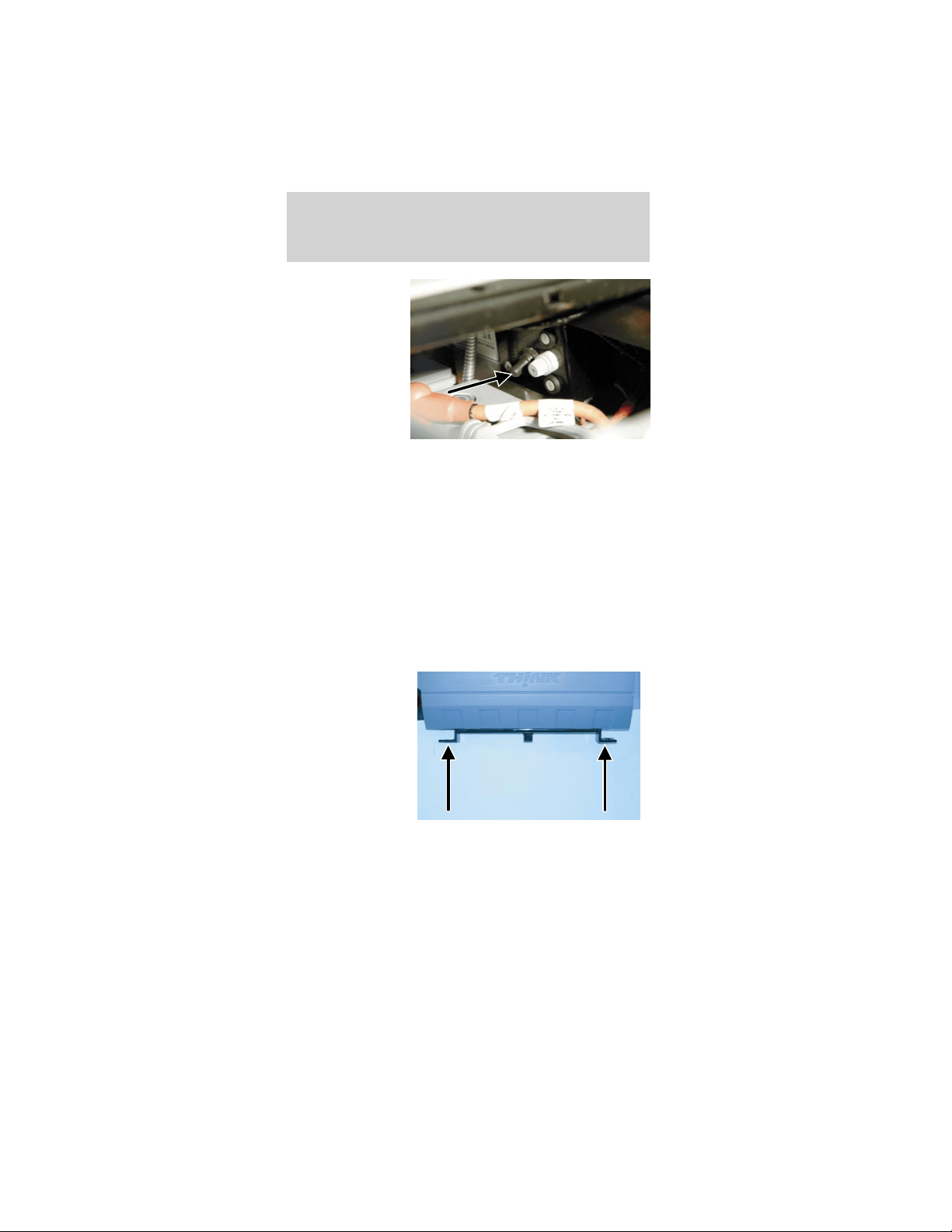
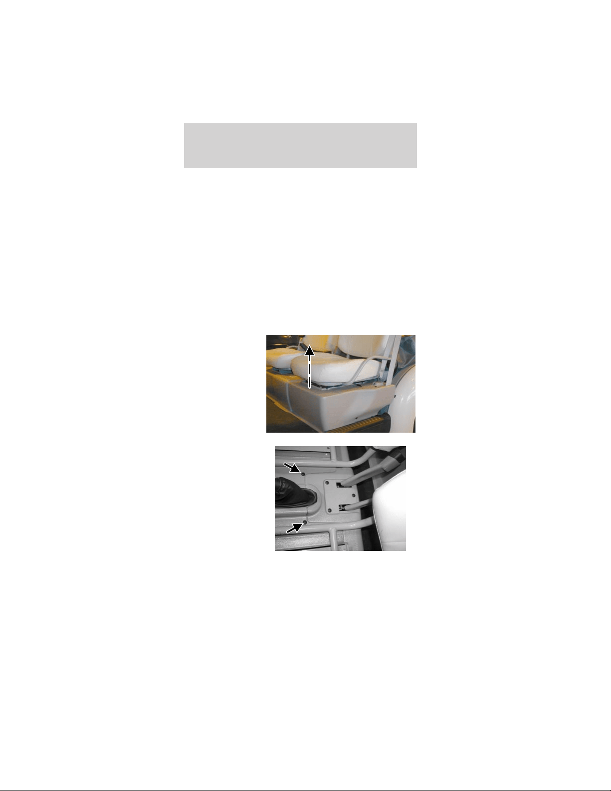
To check the water level in your batteries:
1. Pull straight
up on the front
of the front seat
cushions to
release the
clips.
2. Remove the
two center push
pins.
Maintenance and specifications
81
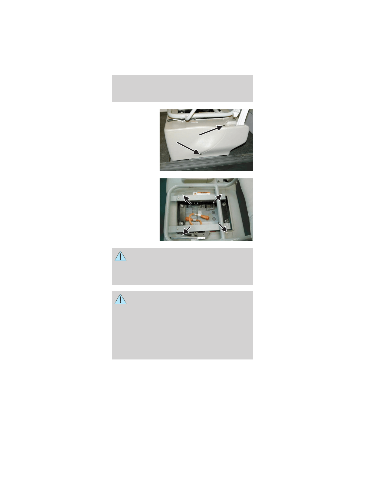
3. From both
sides of the
vehicle, remove
the two push
pins. (Driver
side shown;
passenger side
similar)
4. From both
sides of the
vehicle, remove
four bolts from
beside the seat
frame. (Driver
side shown;
passenger side
is similar.)
Do not touch the battery terminals. Also, do
not lay any tools on the batteries and never
connect one battery terminal with another with
any tool or metal object laid across the top of the
battery.
This vehicle contains a high voltage
electrical system. Serious injury, death,
and/or property damage may result if this vehicle
is not properly used, charged or serviced as stated
in this manual. Read this owner’s guide prior to
use, charging, or servicing this vehicle. Do not
drill, cut, or modify any part of this vehicle, as
high voltage wiring is present. Do not use jumper
cables. Only charge this vehicle with an approved
GFCI cord as stated in Battery charging.
Maintenance and specifications
82
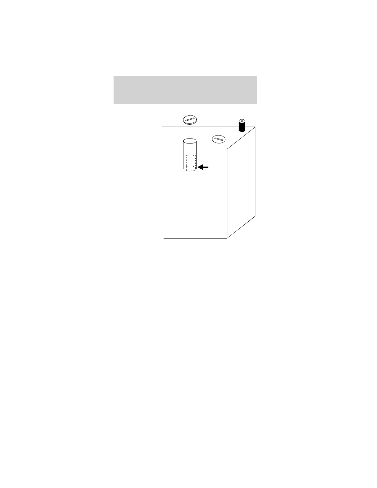
5. Inside each
cell opening is a
slotted cup
protruding
down into the
battery cell. If
battery fluid is
visible in the
slotted cup,
reinstall the
cap. If no fluid
is visible in the
slotted cup in
the battery cell,
carefully add
demineralized
water or
distilled water
until the battery
fluid level
reaches 1/8”
from the
bottom of the slotted cup. Do not overfill.
6. When you have completed adding water, make
sure each battery cell cap is securely installed. Wipe
any spilled water off the top of the battery.
7. Reinstall the body component(s) in reverse order
of removal and tighten the bolts securely.
Maintenance-free type batteries
If your vehicle is equipped with maintenance-free
batteries, it does not require additional water during
its life of service. Removing the caps could void the
battery warranty.
BRAKE FLUID
The brake fluid switch will illuminate the brake icon
on the gauge if the brake fluid falls below a safe
level.
Maintenance and specifications
83
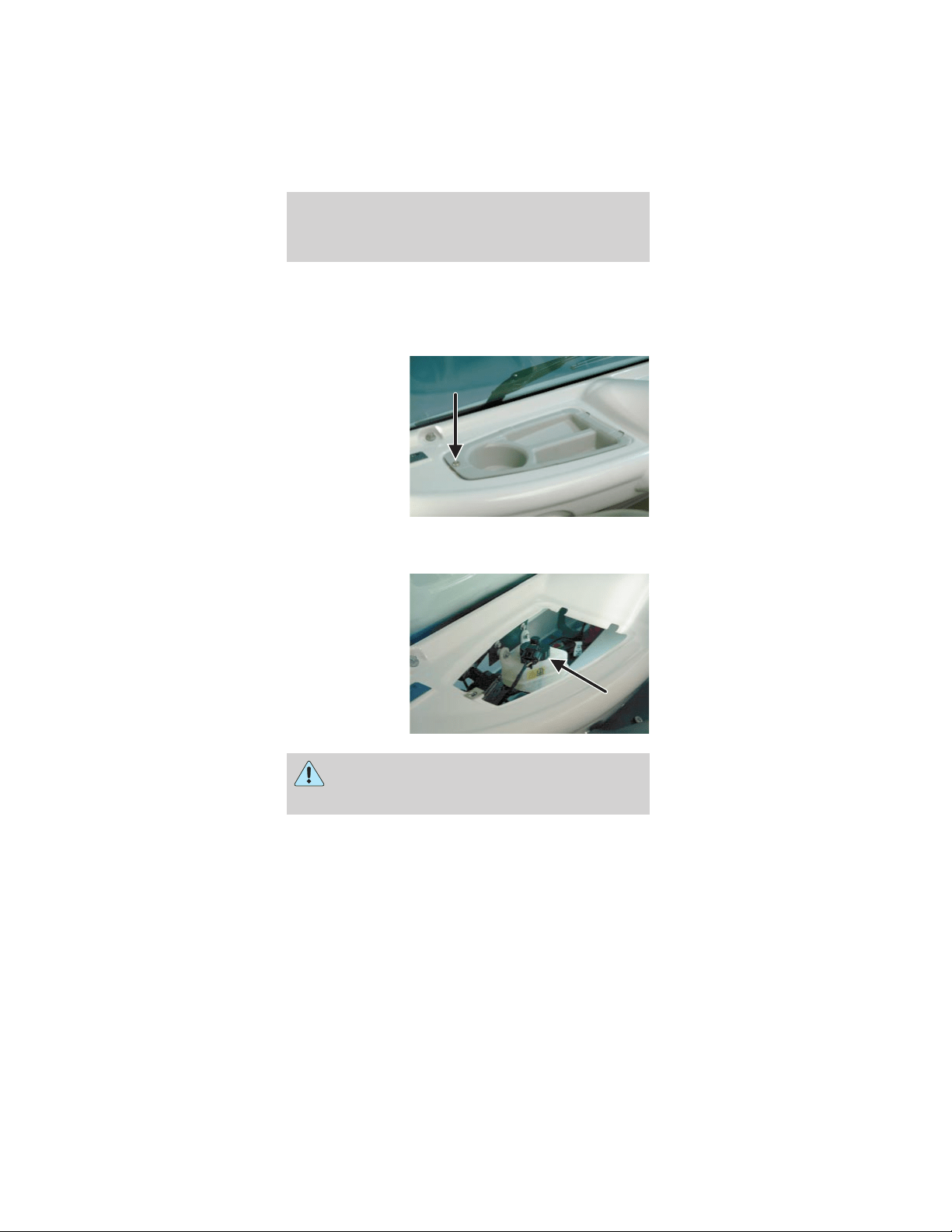
Do not allow any brake fluid to be spilled on
the vehicle’s finished surfaces, as it will cause
discoloration and damage.
To check and add brake fluid:
1. Remove the
scrivet and
remove the
driver side
storage tray.
2. Inspect the brake fluid level at the side of the
reservoir.
3. Remove the
brake reservoir
cap to add
brake fluid as
necessary.
Always use High Performance Dot 3 brake
fluid. Use of other non-Dot 3 fluid could
result in loss of brakes.
4. Reinstall the brake reservoir cap. Wipe off any
excess brake fluid.
5. Reinstall the driver side storage tray and tighten
the scrivet securely.
Maintenance and specifications
84
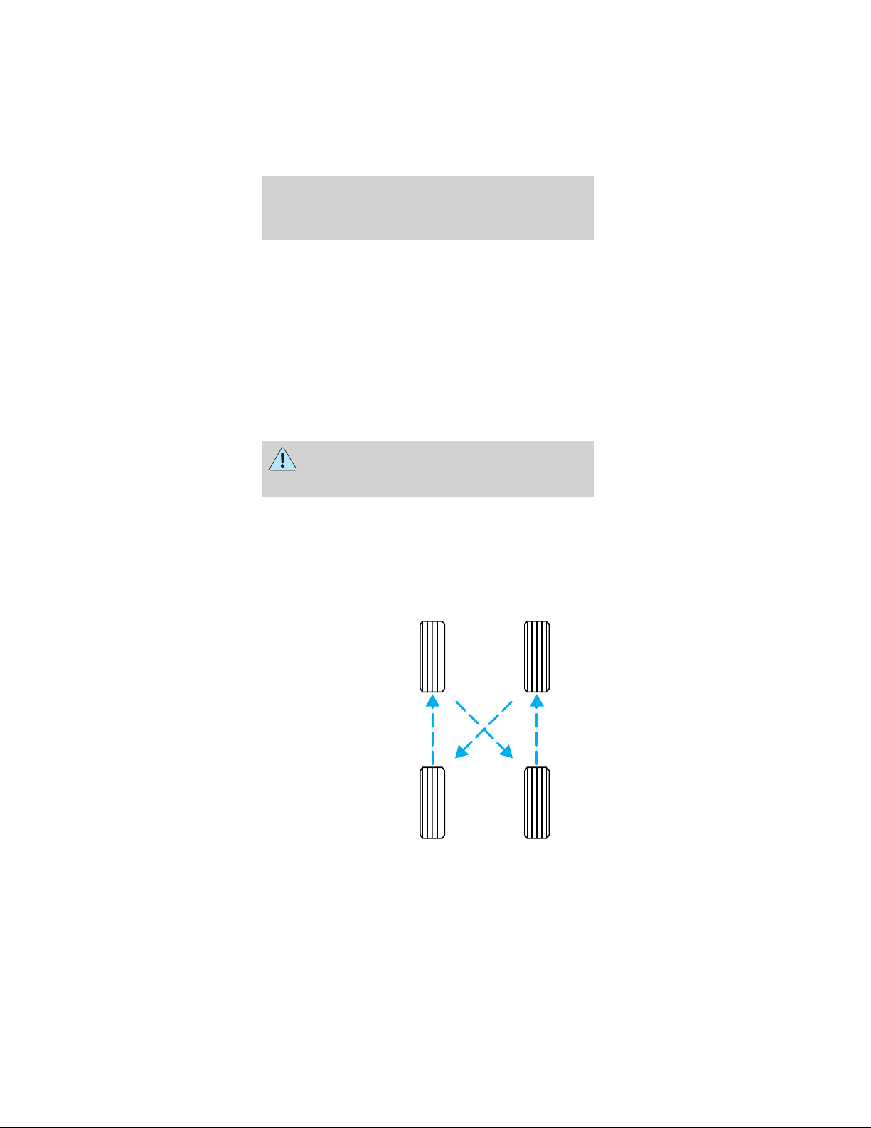
SERVICING YOUR TIRES
Checking the tire pressure
• Use an accurate tire pressure gauge.
• Check the tire pressure when tires are cold, after
the vehicle has been parked for at least one hour
or has been driven less than 5 km (3 miles).
• Adjust tire pressure to recommended
specifications found on the Certification Label
located on the roof panel towards the rear of the
vehicle.
Improperly inflated tires can affect vehicle
handling and can fail suddenly, possibly
resulting in loss of vehicle control.
Tire rotation
Because your vehicle’s tires perform different jobs,
they often wear differently. To make sure your tires
wear evenly and last longer, rotate them as indicated
in the scheduled maintenance guide. If you notice
that the tires wear unevenly, have them checked.
• Four tire
rotation
Maintenance and specifications
85
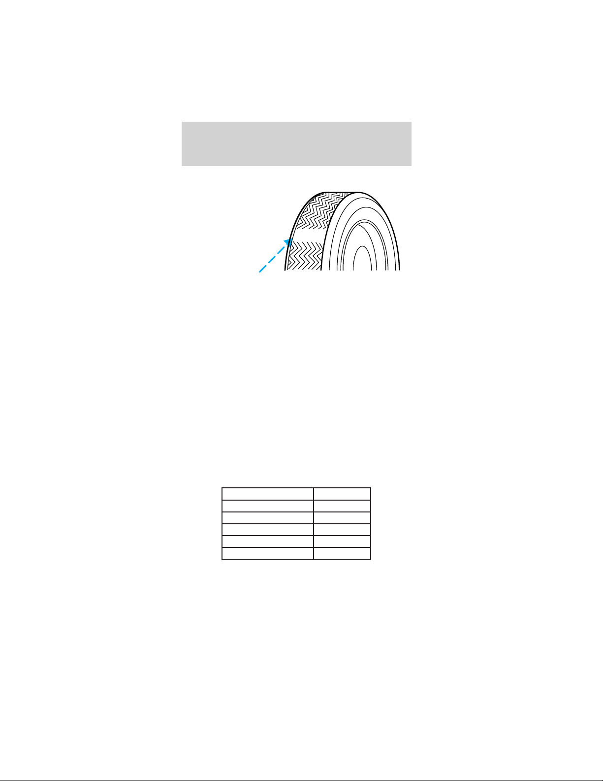
Replacing the tires
Replace the
tires when the
wear band is
visible through
the tire treads.
Your TH!NK neighbor is equipped with either
standard street or turf tires. The load rating for
these tires is 470 kg (1036 lbs). These tires also
comply with the requirements of Federal motor
vehicle safety standards (FMVSS) 109 and FMVSS
119, and carry a “DOT” marking, indicating they may
be used for highway service. TH!NK recommends
that any replacement tires you purchase carry the
DOT marking, showing they are approved for
highway service. DO NOT replace with non-OE tires
designated “NHS” (Not for Highway Service). OE
tires are available through your TH!NK dealer.
Tires that are larger or smaller than your vehicle’s
original tires may also affect the accuracy of your
speedometer.
PART NUMBERS
Component Part number
Battery (standard) 10655–AA
Battery (optional) 10655–BA
Tire (Street tire) 1531–AA
Tire (Turf tire) 1531–BA
Windshield wiper blade 17528–AA
Maintenance and specifications
86
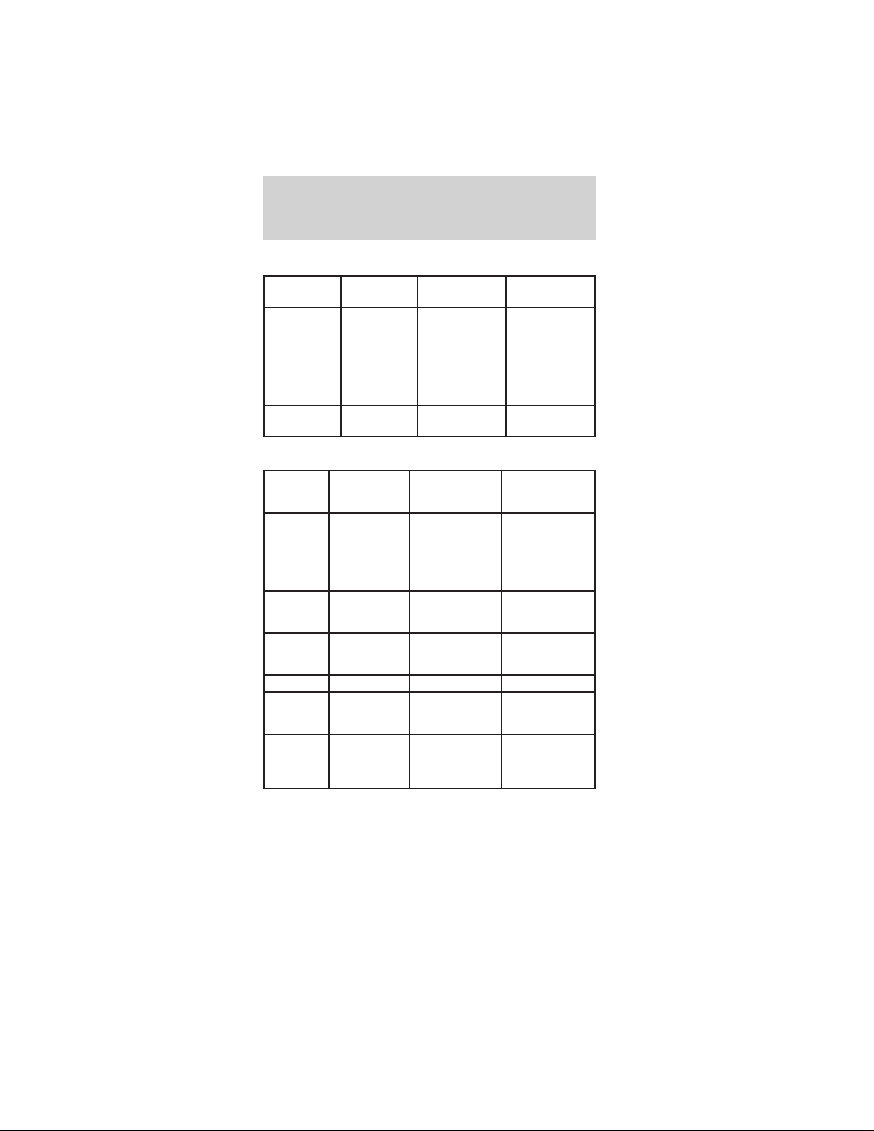
REFILL CAPACITIES
Fluid Ford Part
Name
Application Capacity
Brake fluid Motorcraft
High
Performance
DOT 3
Motor
Vehicle
Brake Fluid
All Fill to line on
reservoir
Gearbox 80W90 All .69 quarts
(.65 Liters)
LUBRICANT SPECIFICATIONS
Items Ford Part
Name or
equivalent
Ford Part
Number
Ford
Specification
Brake fluid Motorcraft
High
Performance
DOT 3 Motor
Vehicle Brake
Fluid
ESA-M6C25-A
and DOT 3
Seat tracks Multi-Purpose
Grease
DOAZ-19584-AA
or
F5AZ-19G209-AA
ESA-M1C93-B
or
ESR-M1C159-A
Lock
cylinders
Penetrating
and Lock
Lubricant
Motorcraft XL-1 None
Gearbox 80W90 XY-80W90–QL WSP-M2C197–A
Half shaft
splines
CV Joint
Grease (High
Temp.)
E43Z-19590-A ESP-M1C207-A
Windshield
washer
fluid
Ultra-clear
Windshield
Washer
Concentrate
C9AZ-19550-AC ESR-M17P5-A
Maintenance and specifications
87
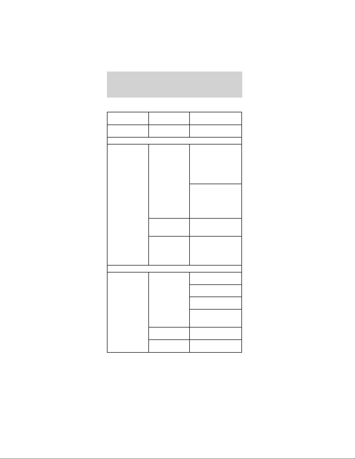
PERIODIC SERVICE SCHEDULE
Regular
Interval
Item Service
Daily service by
owner
Batteries Charge batteries
(after each use only).
Monthly service
by owner or
qualified
technician
Batteries Check electrolyte
level. Add distilled
water or
demineralized water
as necessary per
maintenance and
service manual.
Wash battery tops and
clean terminals with
baking soda/water
solution. Dispose of
waste water
properly.
Tires Check air pressure
and adjust as
necessary.
General vehicle
Wash battery
compartment and
underside of vehicle.
Dispose of waste
water properly.
Semi-annual
service by a
qualified
technician only
(every 50 hours
of operation)
Brake system Check brake shoes
(replace if necessary).
Brake linkage and
pivots
Lubricate brake
slides.
Check brake cables
for damage; replace
as required.
Electrical wiring
and connections
Check for tightness
and damage.
Front wheel
alignment
Check and adjust as
required.
Maintenance and specifications
88
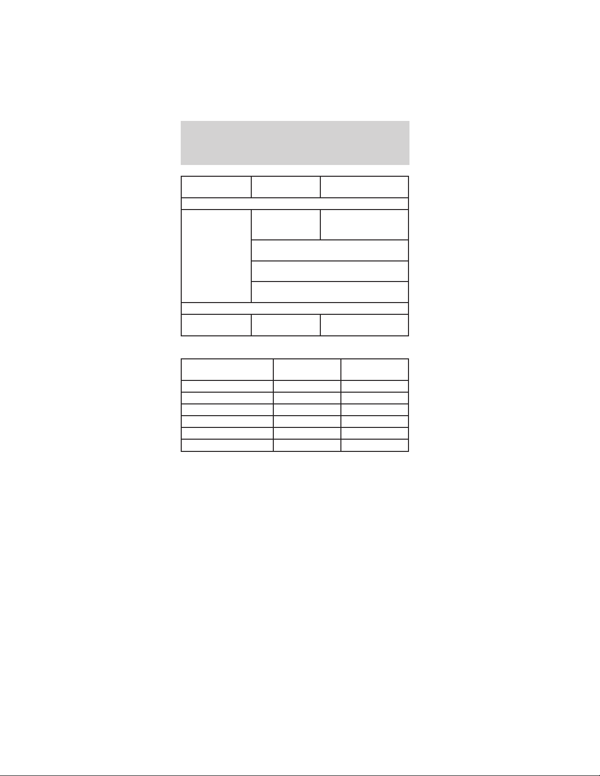
Regular
Interval
Item Service
Annual service
by qualified
technician (every
100 hours of
operation)
Batteries Perform battery tests
per maintenance and
service manual.
Inspect the brake pushrod locknut for
tightness.
Check/fill gearbox fluid to the amount
indicated in refill capacities chart.
Inspect front wheel bearings (repack as
necessary).
16093 kilometers
(10,000 miles)
Tires Rotate the tires
VEHICLE DIMENSIONS
Vehicle dimensions 2 passenger
mm (in)
4 passenger
mm (in)
(1) Overall length 2, 642 (104) 2, 898 (114.1)
(2) Overall width 1, 433 (56.4) 1, 433 (56.4)
(3) Overall height 1, 720 (67.7) 1, 720 (67.7)
(4) Wheelbase 1, 726 (67.9) 1, 980 (77.9)
(5) Track - Street tires 637 (25.1) 637 (25.1)
(5) Track - Turf tires 617 (24.3) 617 (24.3)
Maintenance and specifications
89
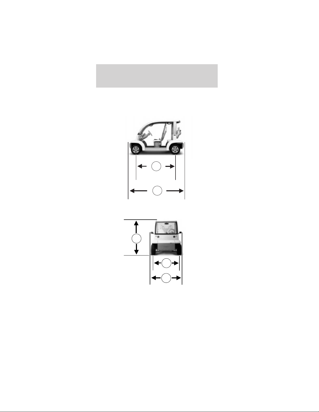
4
1
5
2
3
Maintenance and specifications
90
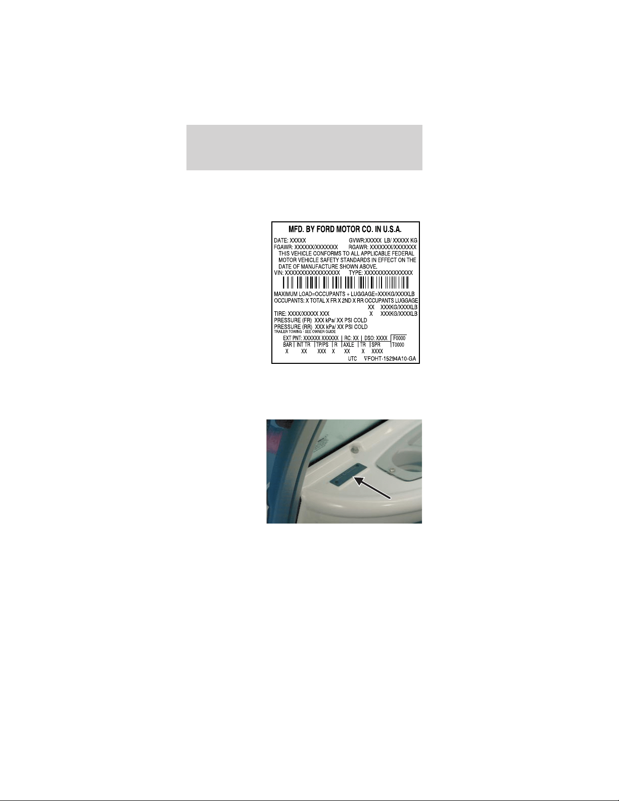
IDENTIFYING YOUR VEHICLE
Certification label (typical lable shown)
The National
Highway Traffic
Safety
Administration
Regulations
require that a
Certification
label be affixed
to a vehicle and
prescribe where
the Certification
label may be
located. The
Certification
label is located
on roof panel
towards the rear of the vehicle.
Vehicle identification number
The vehicle
identification
number is on a
metal tag
located on the
driver side
instrument
panel.
Maintenance and specifications
91

In order to help you service your TH!NK neighbor,
please have the following information available when
contacting a Customer Relationship Center:
• Your telephone number (home and business).
• The name of the dealer and the city where the
dealership is located.
• The year and make of your vehicle.
• The date of vehicle purchase.
• The current odometer reading.
• The vehicle identification number (VIN).
If you still have a complaint involving a warranty
dispute, you may wish to contact the Dispute
Settlement Board (U.S.).
In some states (in the U.S.) you must directly notify
TH!NK Mobility in writing before pursuing remedies
under your state’s warranty laws. TH!NK Mobility is
also allowed a final repair attempt in some states.
In the United States, a warranty dispute must be
submitted to the Dispute Settlement Board before
taking action under the Magnuson-Moss Warranty
Act, or to the extent allowed by state law, before
pursuing replacement or repurchase remedies
provided by certain state laws. This dispute handling
procedure is not required prior to enforcing state
created rights or other rights which are independent
of the Magnuson-Moss Warranty Act or state
replacement or repurchase laws.
THE DISPUTE SETTLEMENT BOARD
(U.S. ONLY)
The Dispute Settlement Board is:
• an independent, third-party arbitration program
for warranty disputes
• available free to owners and lessees of qualifying
TH!NK vehicles
The Dispute Settlement Board may not be available in
all states. TH!NK Mobility reserves the right to
Customer assistance
92

change eligibility limitations, modify procedures
and/or to discontinue this service without notice and
without incurring obligations per applicable state law.
What kinds of cases does the Board review?
Unresolved warranty repair concerns or vehicle
performance concerns as on TH!NK vehicles which
are within the terms of any applicable written new
vehicle warranty are eligible for review, except those
involving:
• a non-TH!NK product
• a non-TH!NK dealership
• sales disputes between customer and dealer
except those associated with warranty repairs or
concerns with the vehicle’s performance as
designed
• a request for reimbursement of consequential
expenses unless a service or product concern is
being reviewed
• items not covered by the New Vehicle Limited
Warranty (including maintenance and wear items)
• alleged personal injury/property damage claims
• cases currently in litigation
• vehicles not used primarily for family, personal or
household purposes (except in states where the
Dispute Settlement Board is required to review
commercial vehicles)
• vehicles with non-U.S. warranties
Concerns are ineligible for review if the New Vehicle
Limited Warranty has expired at receipt of your
application and, in certain states eligibility is
dependent upon the customer’s possession of the
vehicle.
Eligibility may differ according to state law. For
example, see the unique brochures for California,
West Virginia, Georgia and Wisconsin
purchasers/lessees.
Customer assistance
93

Board membership
The Board consists of:
• three consumer representatives
• a TH!NK dealership representative
Consumer candidates for Board membership are
recruited and trained by an independent consulting
firm. The dealership Board member is chosen from
TH!NK dealership management, recognized for their
business leadership qualities.
What the Board needs
To have your case reviewed you must complete the
application in the DSB brochure and mail it to the
address provided on the application form. Some
states will require you to use certified mail, with
return receipt requested.
Your application is reviewed and, if it is determined
to be eligible, you will receive an acknowledgment
indicating:
• The file number assigned to your application.
• The toll-free phone number of the DSB’s
independent administrator.
Your dealership and a TH!NK Mobility representative
will then be asked to submit statements.
To properly review your case, the Board needs the
following information:
• Legible copies of all documents and maintenance
or repair orders relevant to the case.
• The year, make, model, and Vehicle Identification
Number (VIN) listed on your vehicle ownership
license.
• The date of repair(s) and mileage at the time of
occurrence(s).
• The current mileage.
• The name of the dealer(s) who sold or serviced
the vehicle.
Customer assistance
94

• A brief description of your unresolved concern.
• A brief summary of the action taken by the
dealer(s) and TH!NK Mobility.
• The names (if known) of all the people you
contacted at the dealership(s).
• A description of the action you expect to resolve
your concern.
You will receive a letter of explanation if your
application does not qualify for Board review.
Oral presentations
If you would like to make an oral presentation,
indicate YES to question 6 on the application. While
it is your right to make an oral presentation before
the Board, this is not a requirement and the Board
will decide the case whether or not an oral
presentation is made. An oral presentation may be
requested by the Board as well.
Making a decision
Board members review all available information
related to each complaint, including oral
presentations, and arrive at a fair and impartial
decision. Board review may be terminated at any
time by either party.
Every effort is made to decide the case within 40
days of the date that all requested information is
received by the Board. Since the Board generally
meets once a month, it may take longer for the
Board to consider some cases.
After a case is reviewed, the Board mails you a
decision letter and a form on which to accept or
reject the Board’s decision. The decisions of the
Board are binding on TH!NK (and, in some cases, on
the dealer) but not on consumers who are free to
pursue other remedies available to them under state
or federal law.
Customer assistance
95

To request a DSB Brochure/Application
For a brochure/application, speak to your dealer or
write/call to the Board at the following
address/phone number:
Dispute Settlement Board
P.O. Box 5120
Southfield, MI 48086–5120
1–800–428–3718
You may also contact the North American Customer
Relationship Center at 1-800-392-3673 (Ford), TDD
for the hearing impaired: 1-800-232-5952 or by
writing to the Center at the following address:
Ford Motor Company
Customer Relationship Center
16800 Executive Plaza Drive
P.O. Box 6248
Dearborn, Michigan 48121
ORDERING ADDITIONAL OWNER’S
LITERATURE
To order the publications in this portfolio, contact
Helm, Incorporated at:
HELM, INCORPORATED
P.O. Box 07150
Detroit, Michigan 48207
Or call:
For a free publication catalog, order toll free:
1-800-782-4356
Monday-Friday 8:00 a.m. - 6:00 p.m. EST
(Items in this catalog may be purchased by credit
card holders only.)
Customer assistance
96

REPORTING SAFETY DEFECTS (U.S. ONLY)
If you believe
that your
vehicle has a
defect which
could cause a
crash or could
cause injury or
death, you should immediately inform the National
Highway Traffic Safety Administration (NHTSA) in
addition to notifying TH!NK Mobility.
If NHTSA receives similar complaints, it may open
an investigation, and if it finds that a safety defect
exists in a group of vehicles, it may order a recall
and remedy campaign. However, NHTSA cannot
become involved in individual problems between
you, your dealer, or TH!NK Mobility.
To contact NHTSA, you may either call the Auto
Safety Hotline toll-free at 1–800–424–9393 (or
366–0123 in the Washington D.C. area) or write to:
NHTSA
U.S. Department of Transportation
Washington, D.C. 20590
You can also obtain other information about motor
vehicle safety from the Hot-line.
Customer assistance
97

Your satisfaction is our #1 goal. If you have
questions or concerns with your TH!NK vehicle, we
suggest you follow these steps:
1. Contact your Sales Representative or Service
Advisor at your selling/servicing dealership.
2. If the inquiry or concern remains unresolved,
contact the Sales Manager or Service Manager at the
dealership.
3. If the inquiry or concern cannot be resolved at
the dealership level, please contact the TH!NK
Mobility Customer Relationship Center.
In the United States:
TH!NK Mobility
Customer Relationship Center
16800 Executive Plaza Drive
P.O. Box 6248
Dearborn, MI 48121
1–800–252–4221
TDD for hearing impaired:
1–800–232–5952
INTRODUCTION
Ford Motor Company and your selling dealer
thank you for selecting one of our quality products.
Our commitment to you and your TH!NK vehicle
begins with quality protection and service.
When you need warranty repairs, your selling dealer
would like you to return to it for that service, but
you may also take your TH!NK vehicle to another
TH!NK dealership authorized for warranty repairs.
Certain warranty repairs require special training
though, so not all dealers are authorized to perform
all warranty repairs. That means that, depending on
the warranty repair needed, the TH!NK vehicle may
need to be taken to another dealer. If a particular
dealership cannot assist you, then contact the
Customer Relationship Center at 1–800–252–4221.
Warranty information
98

This chapter explains in detail the warranty
coverages that apply to your 2002–model TH!NK
vehicle. If you bought a previously owned
2002–model TH!NK vehicle, you are eligible for any
remaining warranty coverages.
Ford Motor Company or Ford Motor Vehicle
Assurance Company (a subsidiary of Ford Motor
Company, The American Road, Dearborn, MI 48121)
provides the New TH!NK Vehicle Limited
Warranty. See the section titled The New TH!NK
Vehicle Limited Warranty for your 2002–model
TH!NK vehicle in this chapter.
If you are interested in knowing whether the
warranty coverage is provided by Ford Motor
Company or Ford Motor Vehicle Assurance
Company, call the Customer Relationship Center at
1–800–252–4221. The warranty coverage you receive
and your dealer’s handling of any warranty covered
repair will be the same regardless of the warranty
provider.
IMPORTANT INFORMATION YOU SHOULD
KNOW
If you need customer assistance
Your TH!NK dealer is available to assist you with all
your automotive needs. Please follow the procedures
outlined at the beginning of this chapter.
Know when your warranty begins
Your Warranty Start Date is the day you take
delivery of your new TH!NK vehicle or the day it is
first put into service (for example, as a dealer
demonstrator), whichever occurs first.
Warranty information
99

Check your TH!NK vehicle
We try to check TH!NK vehicles carefully at the
assembly plant and the dealership, and we usually
correct any damage to paint, body panels,
upholstery, or other appearance items. But
occasionally something may slip past us, and a
customer may find that a vehicle was damaged
before he or she took delivery. If you see any
damage when you receive your vehicle, notify your
dealership within one week.
Maintain your TH!NK vehicle properly
Your glove compartment contains an Owner’s
Guide which indicates the scheduled maintenance
required for your TH!NK vehicle. Proper
maintenance guards against major repair expenses
resulting from neglect or inadequate maintenance,
and may help increase the value you receive when
you sell or trade your Think vehicle.
It is your responsibility to make sure that all of the
scheduled maintenance is performed and that the
materials used meet TH!NK engineering
specifications. Failure to perform scheduled
maintenance as specified in the Owner’s Guide will
invalidate warranty coverage on parts affected by
the lack of maintenance. Make sure that receipts for
completed maintenance work are retained with the
vehicle and confirmation of maintenance work is
always entered in your Owner’s Guide.
Your TH!NK dealership has factory-trained
technicians who can perform the required
maintenance using genuine TH!NK parts. The
dealership looks forward to meeting your every
service need to maximize your satisfaction with your
TH!NK vehicle.
Warranty information
100

Who pays for warranty repairs?
You will not be charged for covered warranty repairs
made during the warranty periods for Bumper to
Bumper, Safety Restraint, or Corrosion.
You will not be charged for repairs to defective
batteries during the first 12 months after the
warranty start date.
Your battery is covered on a customer-participation
basis after the first 12 months in service.
Some states have mandated alternate time coverage
periods for parts of your vehicle (e.g. seatbelts).
Some states and/or local governments may require a
tax on a portion of warranty repairs. Where
applicable law allows, the tax must be paid by you,
the owner of the vehicle.
During the Bumper to Bumper Warranty period,
dealers may receive instructions to provide no-cost,
service-type improvements-not originally included in
your Owner’s Guide- intended to increase your
overall satisfaction with your vehicle.
Sometimes TH!NK may offer a special adjustment
program to pay all or part of the cost of certain
repairs beyond the terms of the applicable warranty.
Check with your dealer or call 1–800–252–4221 to
learn whether any adjustment program is applicable
to your TH!NK vehicle. Please have your vehicle
identification number available.
Warranty information
101

THE NEW TH!NK VEHICLE LIMITED WARRANTY
FOR YOUR 2002–MODEL TH!NK VEHICLE
Your NEW TH!NK VEHICLE LIMITED WARRANTY gives
you specific legal rights. You may have other rights that
vary from state to state. The New TH!NK Vehicle
Limited Warranty is the only express warranty applicable
to your TH!NK vehicle. Neither Ford Motor Company or
Ford Motor Vehicle Assurance Company assumes nor
authorizes anyone to assume for it any other obligation
or liability in connection with your TH!NK vehicle or this
warranty.
Ford Motor Company, Ford Motor Vehicle Assurance
Company and your dealer are not responsible for any
time that you lose, for any inconvenience you might be
caused, for the loss of your transportation, or for any
other incidental or consequential damages you may
have.
You may have some implied warranties. For example,
you may have:
• an implied warranty of merchantability (that the
TH!NK vehicle is reasonably fit for the general
purpose for which it was sold); or
• an implied warranty of fitness for a particular
purpose (that the TH!NK vehicle is suitable for your
special purposes.)
These implied warranties are limited, to the extent
allowed by law, to the time period covered by the
written warranties, or to the applicable time period
provided by state law, whichever period is shorter.
Some states do not allow Ford Motor Company or Ford
Motor Vehicle Assurance Company to limit how long an
implied warranty lasts or to exclude or limit incidental
or consequential damages, so the limitation and
exclusions described above may not apply to you.
Note: If you are an eligible U.S. owner and have a
warranty concern unresolved by your dealer, you may
use the services of the Dispute Settlement Board. See
the Dispute settlement board in the Customer
assistance chapter.
Warranty information
102

Quick Reference: Warranty Coverage
This chart gives a general summary of your warranty
coverage provided by Ford Motor Company or Ford
Motor Vehicle Assurance Company under the New
TH!NK Vehicle Limited Warranty. Please refer to
the description of warranty coverage for more
specific information.
For more details on coverage, see What is covered
and What is not covered in this chapter.
Type of Coverage Years in Service Miles
Bumper to Bumper 3 years Unlimited miles
Battery 3 years* Unlimited miles
Safety Restraint 5 years Unlimited miles
Corrosion 5 years Unlimited miles
* Customer participation (pro-rated coverage) after 12
months (regardless of miles driven). See details of battery
coverage for percentage Ford Motor Company will pay.
What is covered
The New TH!NK Vehicle Limited Warranty
coverage is provided by Ford Motor Company or
Ford Motor Vehicle Assurance Company, a subsidiary
of Ford Motor Company. These coverages include
Bumper to Bumper Coverage, Battery Coverage,
Safety Restraint Coverage, and Corrosion Coverage.
Bumper to Bumper Coverage
Under your New TH!NK Vehicle Limited Warranty,
Bumper to Bumper Coverage begins at the warranty
start date and lasts for three years regardless of
miles driven. During this coverage period, authorized
TH!NK dealers will repair, replace, or adjust all parts
on your TH!NK vehicle that are defective in
factory-supplied materials or workmanship. Items or
conditions that are not covered by the New TH!NK
Vehicle Limited Warranty are described in What’s
not covered in this chapter.
When making warranty repairs on your TH!NK
vehicle, the dealer will use TH!NK parts or
Warranty information
103

remanufactured or other parts that are authorized
by TH!NK. In certain instances, TH!NK may
authorize repairs at other than TH!NK dealer
facilities.
Battery Coverage
Under your New TH!NK Vehicle Limited Warranty,
full battery coverage begins on the warranty start
date and lasts for 12 months. During this time
period, Ford Motor Company or Ford Motor Vehicle
Assurance Company warrants your TH!NK vehicle’s
battery against defects in factory supplied materials
or workmanship. After the first 12 months in service
(until the 36 month regardless of miles driven), a
defective battery will be replaced on a
customer-participation basis:
• For the 13th month through 18th month in
service, Ford Motor Company will pay 60% of the
cost of the replacement battery.
• For the 19th month through 24th month of
service, Ford Motor Company will pay 40% of the
cost of the replacement battery.
• For the 25th month through 30th month of
service, Ford Motor Company will pay 20% of the
cost of the replacement battery.
• For the 31st month through 36th month of
service, Ford Motor Company will pay 10% of the
cost of the replacement battery.
The percentage Ford Motor Company will pay is
applied to the present suggested retail price of the
new replacement battery for your TH!NK vehicle.
Labor required to test and replace a defective
battery has full coverage under the terms of the
Battery Warranty. Towing, if needed, is covered
under the terms of the Roadside Assistance
Program. See Roadside Assistance in this chapter.
Warranty information
104

Safety Restraint Coverage
Under your New TH!NK Vehicle Limited Warranty,
Safety Restraint Coverage begins at the warranty
start date and lasts for five years regardless of miles
driven.
During this coverage period, Ford Motor Company
or Ford Motor Vehicle Assurance Company warrants
your TH!NK vehicle’s safety belts against defects in
factory-supplied materials or workmanship.
Corrosion Coverage
Under your New TH!NK Vehicle Limited Warranty,
Corrosion Coverage begins at the warranty start date
and covers body panels against corrosion due to a
defect in factory-supplied materials or workmanship.
Corrosion Coverage (which lasts for 5 years,
regardless of miles driven) only applies if the
corrosion causes perforation (holes) in body panels.
If corrosion does not cause perforation (holes), and
is not the result of usage and/or environmental
conditions, paint damage is covered under the terms
of the Bumper to Bumper Warranty (3 years
regardless of miles driven).
For damage caused by airborne material
(environmental fallout) — where there is no factory
related defect involved and therefore no warranty,
our policy is to cover paint damage due to airborne
material for 12 months.
What is not covered
Damaged caused by:
• accidents, collision or objects striking the TH!NK
vehicle
• theft, vandalism, or riot
• freezing
• fire or explosion
• misusing the TH!NK vehicle, such as driving over
curbs, overloading or racing
Warranty information
105

• altering or modifying the TH!NK Vehicle —
including the body, chassis, or components —
after the TH!NK Vehicle leaves TH!NK’s Mobility’s
control
• non-TH!NK parts installed after the TH!NK vehicle
leaves TH!NK’s Mobility’s control
• tampering with the TH!NK vehicle
• using contaminated or improper fluids
• customer-applied chemicals or accidental spills
• driving through water deep enough to cause
electrical system damage
Damage caused by use and/or the environment
Your New TH!NK Vehicle Limited Warranty does not
cover surface rust and deterioration of paint, trim,
upholstery, and other appearance items that result
from use and/or exposure to the elements. Here are
examples:
• stone chips, scratches (some examples are on
paint and glass)
• dings, dents
• cuts, burns, punctures or tears
• road salt, tree sap
• bird and bee droppings
• lightning, hail
• windstorm
• earthquake
• water or flood
Damage caused by improper maintenance
Your New TH!NK Vehicle Limited Warranty does not
cover damage caused by failure to maintain the
TH!NK vehicle, improperly maintaining the TH!NK
vehicle, or using the wrong part, oil, lubricants, or
fluids. See the Maintenance and specifications
chapter for the correct fluid types and levels and for
proper ways to maintain your TH!NK vehicle.
Warranty information
106

Maintenance/wear
Your New TH!NK Vehicle Limited Warranty does not
cover:
1. parts and labor needed to maintain the TH!NK
vehicle; and
2. the replacement of parts due to normal wear and
tear.
You, as the owner, are responsible for these items.
Examples are:
• lubricants, other fluids
• brake linings/pads
• tire rotation
• cleaning/polishing
• wiper blades
Tire wear or damage
Normal wear or worn-out tires are not covered by
the New TH!NK Vehicle Limited Warranty. Road
hazard damage such as cuts, snags, bruises, bulges
and impact breaks (potholes and curbs) are not
covered. Any damage caused by a puncture or tire
repair is not covered. In addition, damage from
improper inflation or alignment, tire chains, racing,
spinning (as when stuck in snow or mud), improper
mounting or dismounting is not covered.
Other items and conditions not covered
Your New TH!NK Vehicle Limited Warranty does not
cover:
• non-Ford parts of your TH!NK vehicle, for
example, parts (including glass) installed by body
builders or manufacturers other than Ford Motor
Company
• TH!NK vehicles that have ever been labeled or
branded as “dismantled” “fire,” “flood,” “junk,”
“rebuilt,” “reconstructed,” or “salvaged”; this will
void the New TH!NK Vehicle Limited Warranty
Warranty information
107

• TH!NK vehicles that have been determined to be
a “total loss” by an insurance company; this will
void the New TH!NK Vehicle Limited Warranty
Time limits on coverage
• After the first 12 months in service, wheel
alignment and tire balancing are not covered
unless required by a warranty repair.
ROADSIDE SERVICE ASSISTANCE
Roadside Service Assistance
Your vehicle is covered by the complimentary Ford
Roadside Assistance Program (unless you are driving
a daily rental unit). Under this program Ford will
cover:
• towing to the nearest TH!NK dealership, or towing
to your selling dealership if within 60 miles
The Roadside Assistance Program is separate from
the New TH!NK Vehicle Limited Warranty, but the
program’s time period runs concurrently with
Bumper to Bumper Warranty Coverage (three years
regardless of miles driven). If you need towing after
Bumper to Bumper coverage has ended, Ford can
arrange roadside assistance and charge your credit
card unless the problem is covered by another
TH!NK warranty. Ford will pay the tow charge under
the other warranty.
For emergency roadside assistance, call
1–800–252–4221, 24 hours a day, 365 days a
year.
For daily rental units that must be towed because a
covered part has failed during the Bumper to
Bumper warranty period, Ford will cover towing to
the nearest Ford Motor Company dealership.
Warranty information
108

STATE WARRANTY ENFORCEMENT LAWS
These state laws — sometimes called “lemon laws”
— allow owners to receive a replacement TH!NK
vehicle or a refund of the purchase price, under
certain circumstances. The laws vary from state to
state.
To the extent your state law allows, Ford Motor
Company requires that you first send us a written
notification of any defects or non-conformities that
you have experienced with your TH!NK vehicle.
(This will give us the opportunity to make any
needed repairs before you pursue the remedies
provided by your state’s law.)
In all other states where not specifically required by
state law, Ford Motor Company requests that you
give us the written notice.
Send your written notification to:
Ford Motor Company
Customer Relationship Center
16800 Executive Plaza Drive
P.O. Box 6248
Dearborn, MI 48121
Warranty information
109

A
Audio system
(see Radio) ................ 29
Automatic transaxle
fluid, refill
capacities ................. 87
fluid, specification .. 87
Auxiliary power
point ........................... 27
B
Ball and club
washer ....................... 30
Batteries .................... 79
Batteries - flooded
type ............................ 81
Batteries - maintenance
free ............................. 83
Brakes
fluid, checking and
adding ...................... 83
fluid, refill
capacities ................. 87
fluid,
specifications .......... 87
lubricant
specifications .......... 87
parking .................... 68
Brakes - dual circuit
brake system ............. 69
Brakes - regenerative
brake system ............. 69
Break-in period ........... 2
C
Capacities for refilling
fluids .......................... 87
Certification Label .... 91
Changing a tire ......... 72
Charging ........ 64, 67–68
Child safety
restraints ................... 51
child safety belts .... 51
Child safety seats ...... 52
attaching with tether
straps ....................... 55
in front seat ............ 53
in rear seat .............. 53
LATCH ..................... 58
Cleaning your vehicle
exterior lamps ......... 77
instrument
cluster lens .............. 77
instrument panel .... 77
interior ..................... 78
safety belts .............. 77
washing .................... 76
waxing ..................... 76
wheels ...................... 77
Coolant
refill capacities ........ 87
specifications .......... 87
Cooler ........................ 31
Cupholder(s) ............. 26
Customer Assistance
Ordering additional
owner’s literature ... 96
The Dispute
Settlement Board ... 92
E
Engine
lubrication
specifications .......... 87
refill capacities ........ 87
Index
110

Engine oil
refill capacities ........ 87
specifications .......... 87
F
Floor mats ................. 29
Fluid capacities ......... 87
Fuel
capacity ................... 87
Fuses .................... 70–71
G
Gauges ......................... 4
Golf rack .................... 28
H
Hazard flashers ......... 70
Head restraints ......... 44
Headlamps ................. 12
aiming ...................... 14
bulb specifications .. 22
replacing bulbs ....... 15
turning on and off .. 12
I
Ignition ....................... 60
Infant seats
(see Safety seats) ..... 52
J
Jack ............................ 72
K
Keys
positions of the
ignition .................... 60
L
Lamps
bulb replacement
specifications
chart ........................ 22
headlamps ............... 12
replacing
bulbs ............ 15, 19–21
Lane change indicator
(see Turn signal) ...... 14
Lights, warning and
indicator ...................... 4
Limited warranty .... 102
Lubricant
specifications ............. 87
M
Maintenance and
Care ...................... 88–89
Mirrors ....................... 27
side view mirrors
(manual) ................. 28
Motorcraft parts ........ 86
P
Parts (see Motorcraft
parts) ......................... 86
Power steering
fluid, refill
capacity ................... 87
fluid,
specifications .......... 87
R
Radio .......................... 29
Index
111

S
Safety belts (see Safety
restraints) ............ 45–47
Safety defects,
reporting .................... 97
Safety restraints .. 45–47
cleaning the safety
belts ................... 49, 77
extension assembly 49
for adults ................. 47
for children ............. 50
Safety seats for
children ...................... 52
Sand and seed bottle 29
Scorecard holder ....... 29
Seat belts (see Safety
restraints) .................. 45
Seats .......................... 44
child safety seats .... 52
Specification chart,
lubricants ................... 87
Starting your
vehicle .................. 60, 62
Sunroof
(moonroof) ................ 25
Sweater basket .......... 32
Sweater net ............... 32
T
Tires ........................... 85
checking the
pressure ................... 85
replacing .................. 86
rotating .................... 85
Tires - servicing ........ 85
Transaxle
fluid, refill
capacities ................. 87
lubricant
specifications .......... 87
Trunk expander ........ 33
Turn signal ................ 14
V
Vehicle cover ............. 43
Vehicle dimensions ... 89
Vehicle Identification
Number (VIN) ........... 91
W
Warning lights
(see Lights) ................. 4
Warranty coverage .. 103
Warranty enforcement
laws .......................... 109
Warranty
information ........ 98–101
Washer fluid .............. 24
Waxing your
vehicle ........................ 76
Weather
enclosure ....... 33, 40, 42
Windows
rear wiper/washer ... 23
Windshield washer
fluid and wipers
checking and
cleaning ................... 24
operation ................. 23
Wrecker towing ......... 74
Index
112