Loading ...
Loading ...
Loading ...
STEERING WHEEL SWITCH SYSTEM
Description
(Cont’d)
The steering wheel switch system
uses
an acryl-
ic optical ring, and this optical ring functions
in the same way
as
optical fiber
The optical ring
is
built in the slip ring
The
slip
ring must not be disassembled.
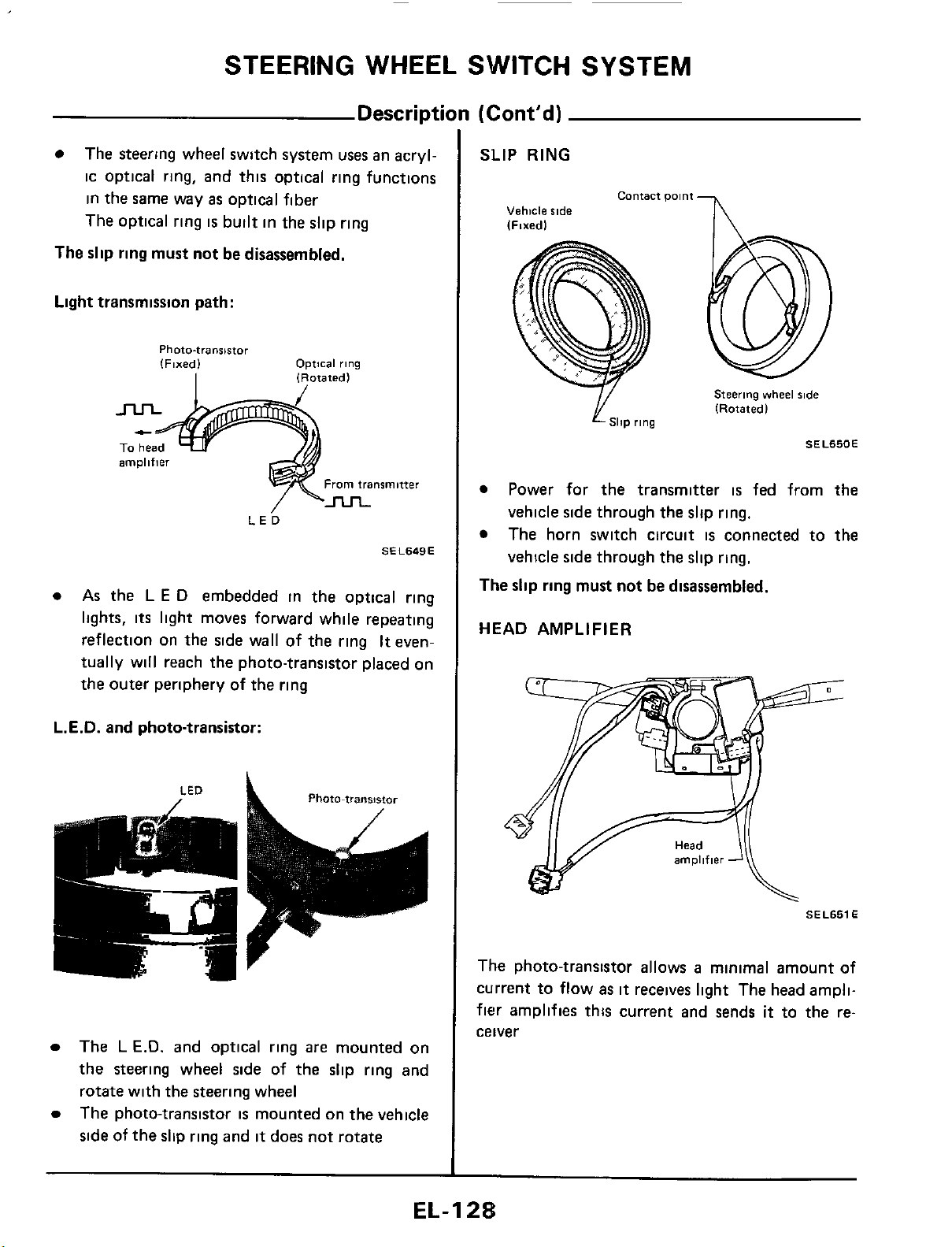
Light transmission path:
Photo-transistor
(Fixed)
Optical
rlng
I
1
Rotated
l
amplifier
From
transmitter
LE^
SEL649E
As
the
L
E
D
embedded in the optical ring
lights,
its
light moves forward while repeating
reflection on the side wall of the ring
It
even-
tually will reach the photo-transistor placed on
the outer periphery
of
the ring
L.E.D.
and photo-transistor:
Photo-transistor
LED
a
,
The
L
E.D.
and optical ring
are
mounted on
the steering wheel side of the slip ring and
rotate with the steering wheel
The photo-transistor
is
mounted on the vehicle
side
of the slip ring and
it
does not rotate
SLIP
RING
contact
Dolnt
-
I\
Vehicle
side
Steering
vvheel
%de
(Rotatedl
SllP
rlng
SEL650E
Power for the transmitter
is
fed from the
vehicle side through the slip ring.
The horn switch circuit
is
connected to
the
vehicle side through the slip ring.
The
slip ring must not be disassembled.
HEAD AMPLIFIER
SEL651
E
The photo-transistor allows
a
minimal amount of
current to flow
as
it
receives light The head ampli-
fier
amplifies this current and sends
it
to the re-
ceiver
EL-I
2%
Loading ...
Loading ...
Loading ...