ELECTRICAL SYSTEII
SECTION
EL
When
you
read
wiring
diagrams
Read
GI
section,
"HOW TO READ WIRING DIAGRAMS".
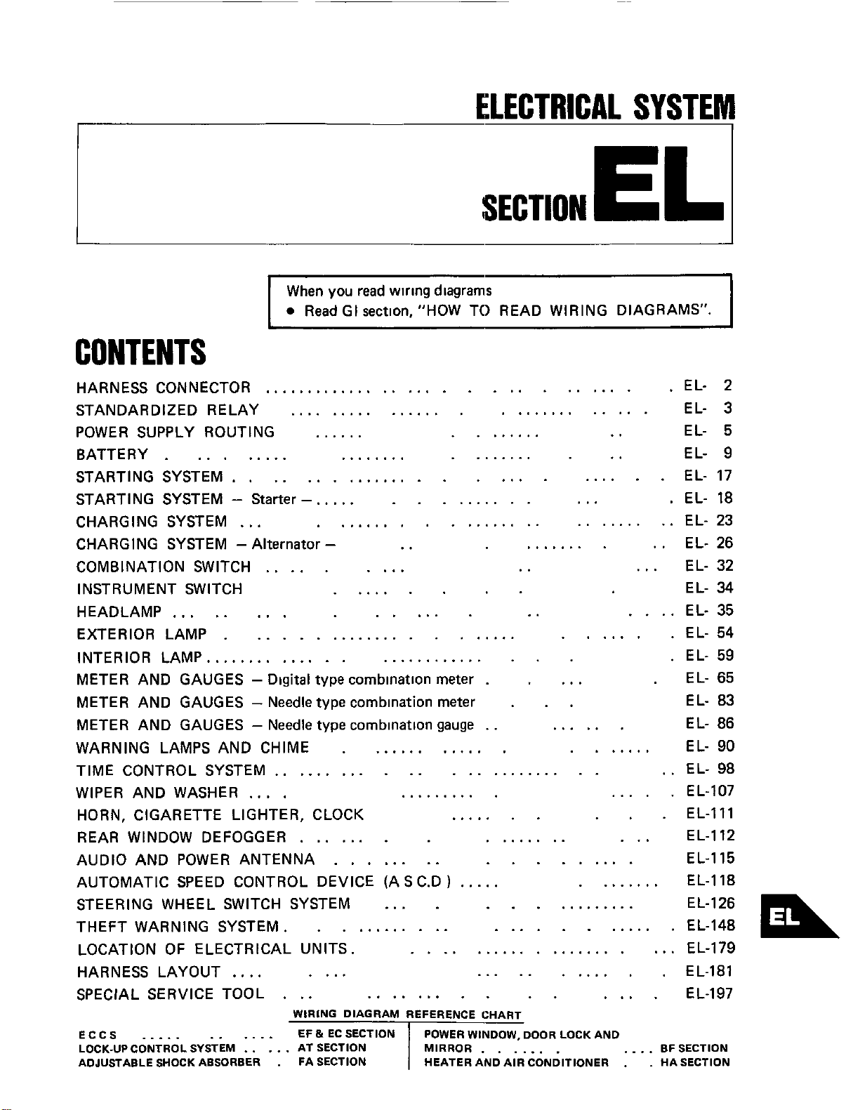
CONTENTS
HARNESS CONNECTOR
..............................
.
EL-
2
STANDARDIZED
RE
LAY
................
.............
EL- 3
........
..
EL-
5
POWER SUPPLY ROUTING
......
BATTERY
.........
........
........
..
EL- 9
STARTING SYSTEM
................
..... ...... EL- 17
STARTING SYSTEM
-
Starter
-.
....
..........
... .
EL- 18
CHARGING SYSTEM
...
..................
.........
EL- 23
CHARGING SYSTEM
-
Alternator
-
..
........
. .
EL-
26
...
EL- 32
COMBINATION SWITCH
.....
....
..
I
N ST
R
U M E NT SWITCH
......
EL-
34
.....
.....
..
....
EL-
35
HEADLAMP
...
EXTERIOR LAMP
......................
......
.
EL-
54
INTERIOR LAMP..
............
............
..
.
EL- 59
METER AND GAUGES
-
Digital
type
combination
meter
.
...
.
EL-
65
METER AND GAUGES
-
Needle
type
combination
meter
.
..
EL-
83
METER AND GAUGES
-
Needle
type
combinatlon
gauge
. .
......
EL-
86
WARNING LAMPS AND CHIME
.
............
.......
EL- 90
TIME CONTROL SYSTEM ............
.............
. .
EL- 98
WIPER AND WASHER
....
..........
.....
EL-107
HORN, CIGARETTE LIGHTER, CLOCK
.......
.
EL-Ill
REAR WINDOW DEFOGGER
....... ........
...
EL-I12
AUDIO AND POWER ANTENNA
........
.........
EL-I15
AUTOMATIC SPEED CONTROL DEVICE (A
S
C.D
1
.....
........
EL-I18
STEERING WHEEL SWITCH SYSTEM
...
............ EL-I26
THEFT WARNING SYSTEM.
...........
............
EL-I48
LOCATION
OF
ELECTRICAL UNITS.
...................
...
EL-I79
HARNESS LAYOUT
....
....
.....
......
.
EL-I81
SPECIAL SERVICE TOOL
.........
..
....
EL-I97
...
WIRING DIAGRAM REFERENCE CHART
LOCK-UPCONTROLSYSTEM AT SECTION MIRROR
....... ....
BF SECTION
ADJUSTABLE SHOCK ABSORBER
.
FA SECTION HEATER AND AIR CONDITIONER
.
.
HA SECTION
ECCS
.....
......
.....
HARNESS
CONNECTOR
LIFT
Description
PUSH
PUSH
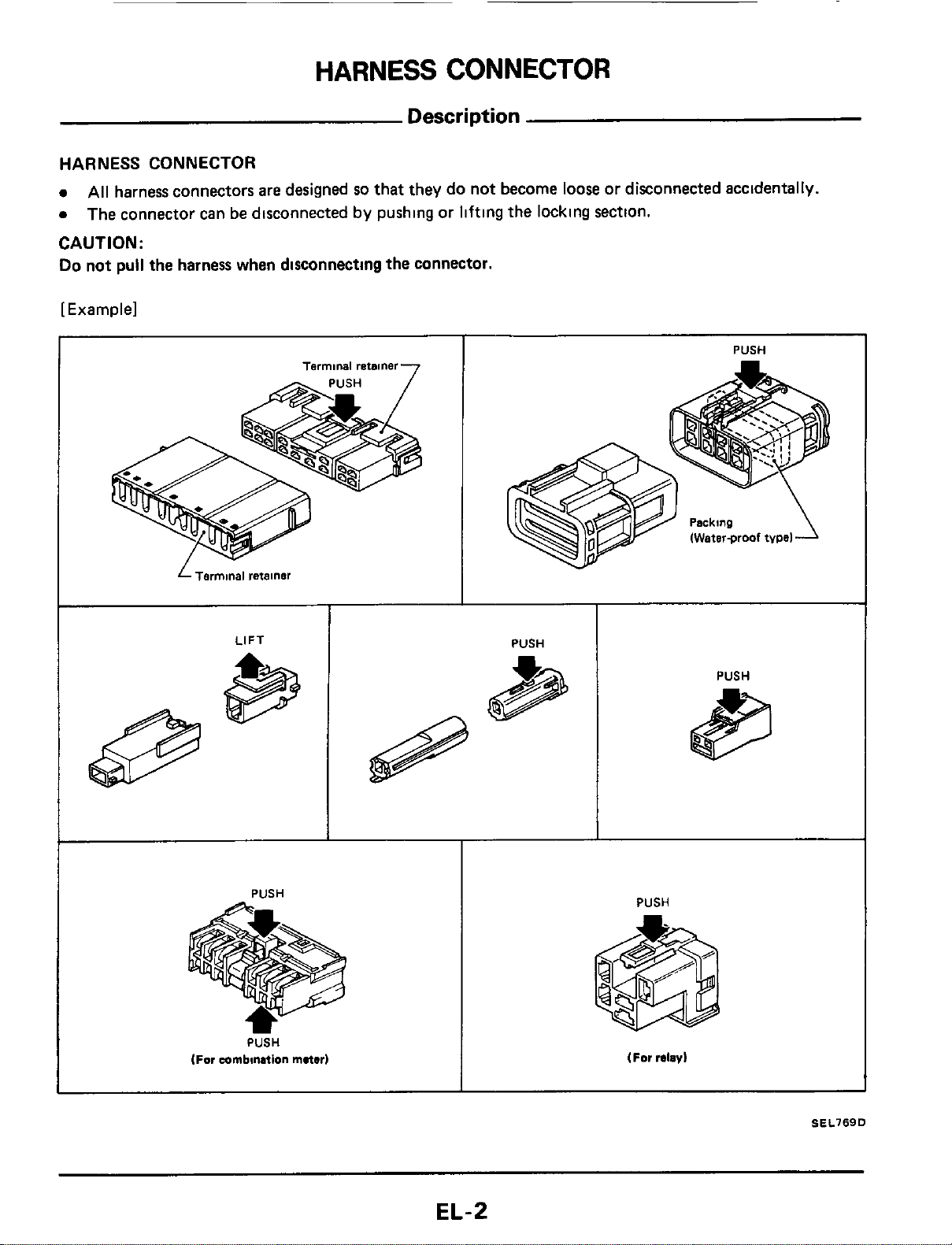
HARNESS CONNECTOR
0
0
CAUTION:
Do
not pull the harness when disconnecting the connector.
[Example]
All
harness connectors are designed
so
that they do not become
loose
or disconnected accidentally.
The connector can be disconnected by pushing or lifting the locking section.
I
PUSH
~~
Terminal
retainer
7
L
Terminal
retainer
IWaterproof
tvpel
PUSH
PUSH
(For
mmbilution
mater)
PUSH
(For
relay)
SEL769D
EL-2
STANDARDIZED
RELAY
Normal Open, Normal Closed and Mixed Type
Relays
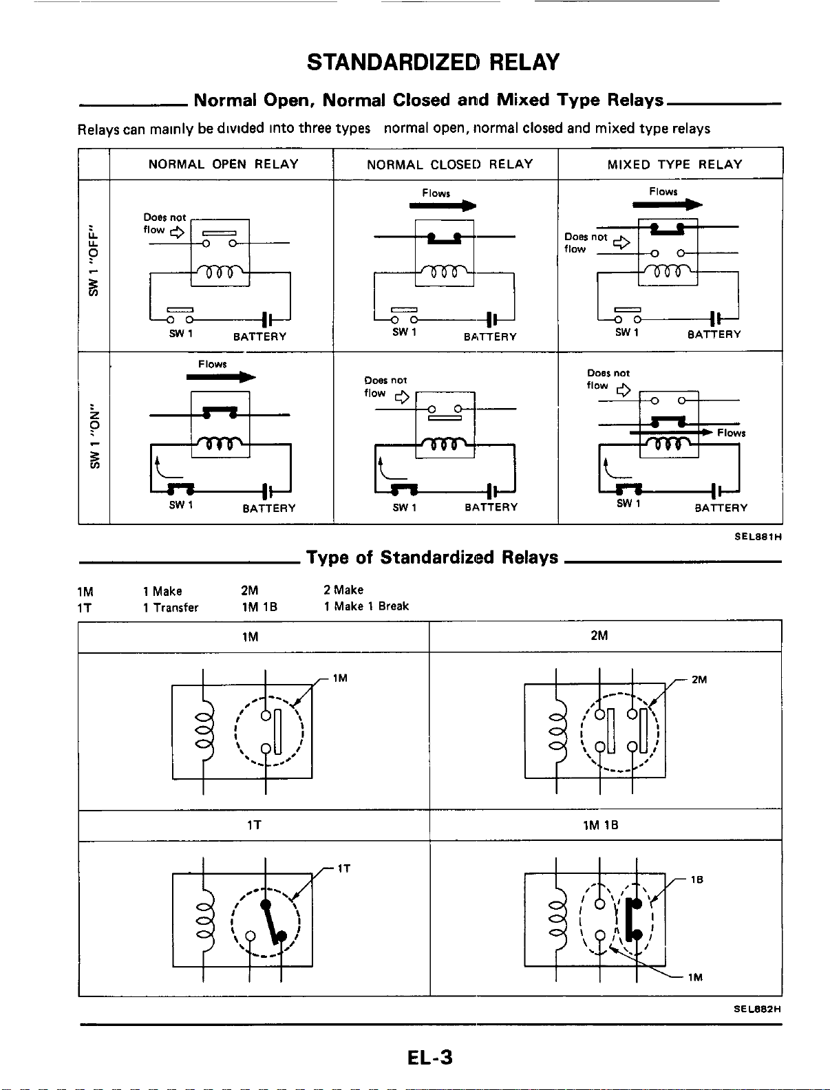
Relays can mainly
be
divided into three types normal open, normal closed and mixed type relays
ooes
not
flow
0
-
s
SW1 BATTERY
NORMAL OPEN RELAY
I
NORMAL CLOSED RELAY
Flows
-
E!;
sw
1 BATTERY
Flows
-
n
sw
1
BATTERY
Doer
not
flow
sw
1 BATTERY
MIXED TYPE RELAY
Flows
-
JOBS
not
low
=&
sw
1 BATTERY
Type
of
Standardized Relays
1M 1 Make
2M
2
Make
1T
1 Transfer
1M 1B
1
Make
1
Break
I I
I
1M 2M
1T
1M
16
I
SEL88ZH
EL-3
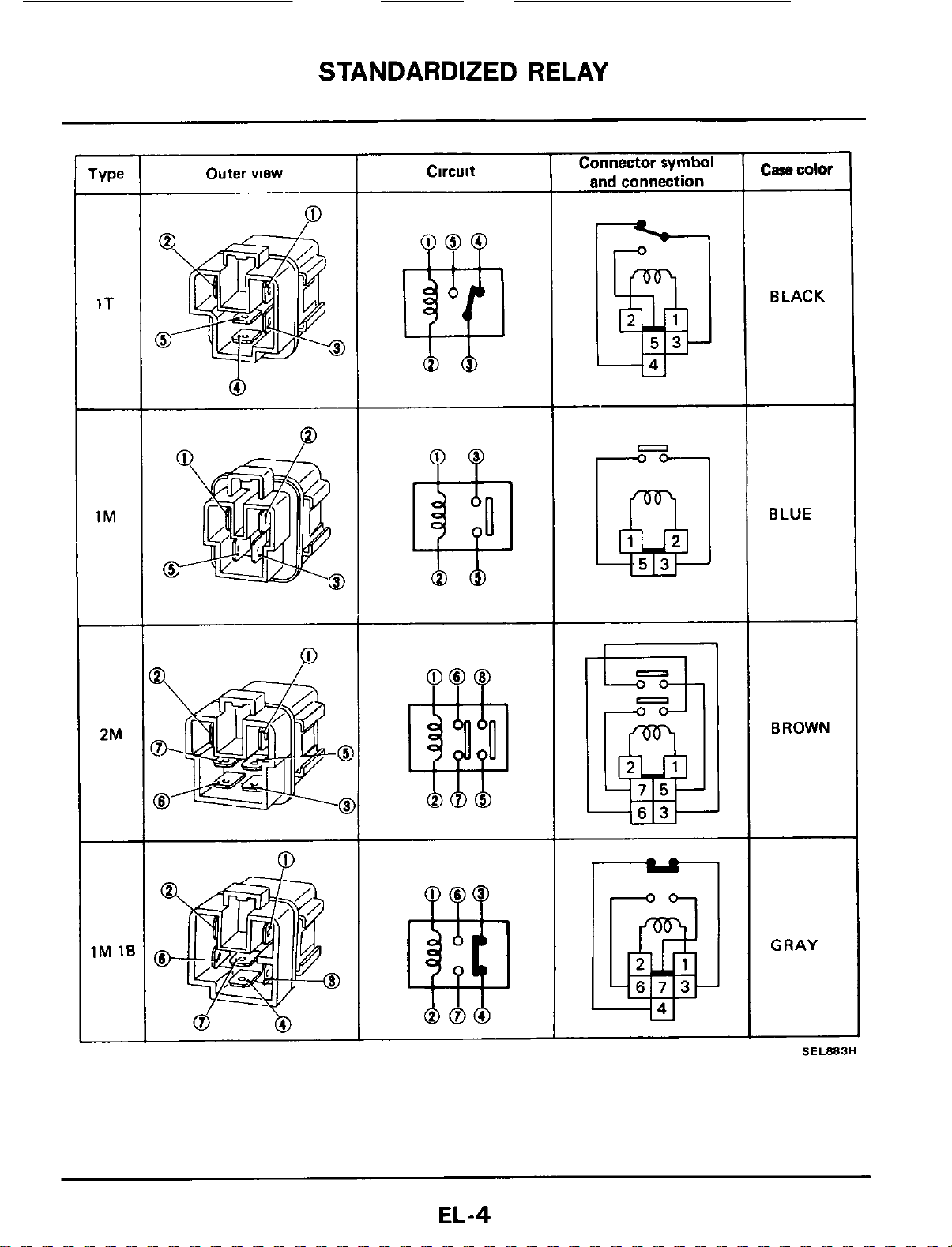
STANDARDIZED RELAY
1T
-
1M
2M
1M
1E
-
Outer
view
0
Q
Circuit
Connector
symbol
and
connection
Case
color
SEL883H
BLACK
BLUE
BROWN
GRAY
EL-4
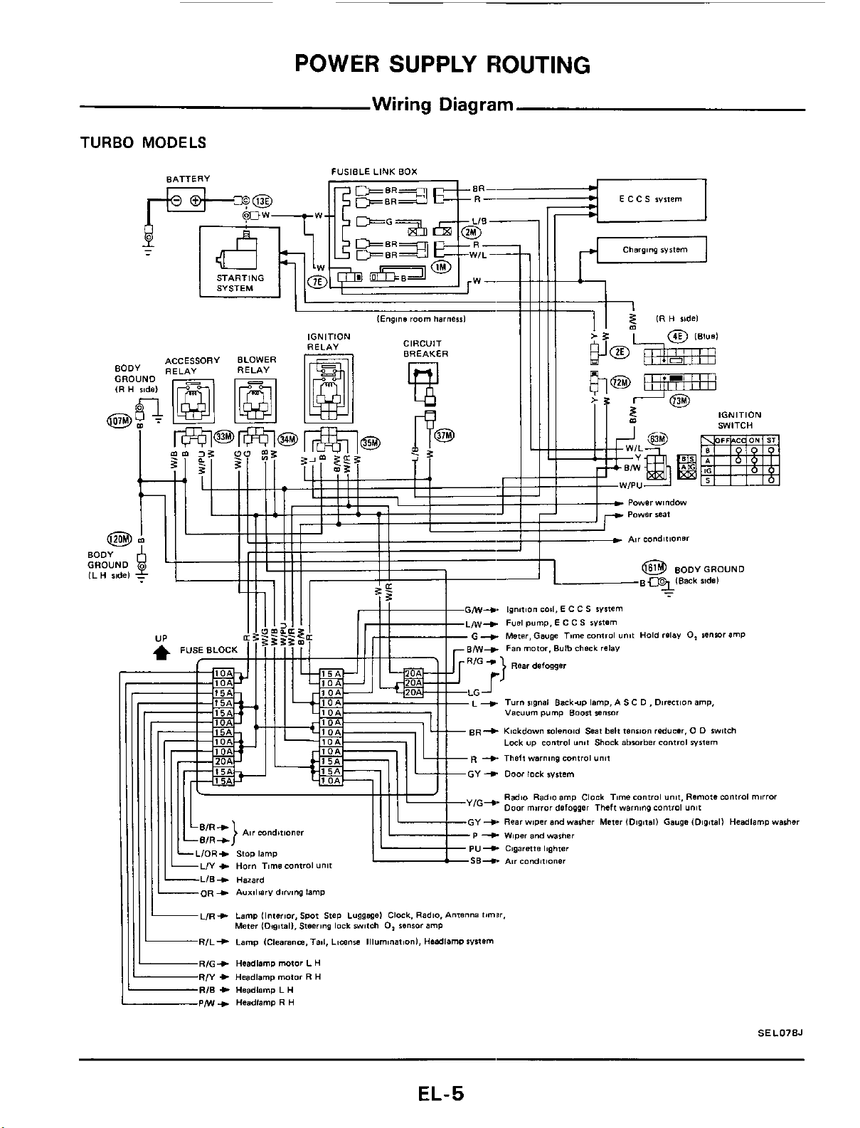
POWER
SUPPLY
ROUTING
Wiring
Diagram
TURBO
MODELS
FUSIBLE LINK
BOX
E
c
C
s
~wem
BATTERY
W--
SYSTEM
Charging
Wstem
I1
rc-7
tYl
IGNITION
SWITCH
-
Powerwindow
CIRCUIT
BREAKER
IGNITION
RELAY
ACCESSORY BLOWER
BODY
GROUND
~3lBack ndd
-
63
MI+
lanilion
~011,
E
C C
S
system
MI--)
Fusl
pump.
E
C C
S
sVIfEm
G
+
Meter. Gauge Time
control
unit
Hold
relay
0,
renwrr
amp
+
Turn
signal
Backup
lamp.
A
S
C
D
,
Direction
amp,
vacuum
pvmp
Boon
sensor
R+
Kickdawn iolmo1d
Seat
belt
tmimn
reducer.
0
D
swfch
Lack
up
control
unit
Shock
abwrrber
control
system
+
Theft
warning
control
"nil
G--C
Radio
Radio
amp
Clack
Time
control
unit.
Remote
Control
mirror
Door
mirror
dsfwgsr Theft
warning
control
unit
+
Rearwiper
and
washer
Meter IDigitall
Gaugs
(Digitall
Hcadlamp
washer
+
Wiwr
and
warher
U--C
Cigarette
Icghter
B+
Air COnditionOr
+
Headlamp
motor
R
H
+
Hsadlamp
L
H
+
Headlemp
R
H
SEL078J
EL-5
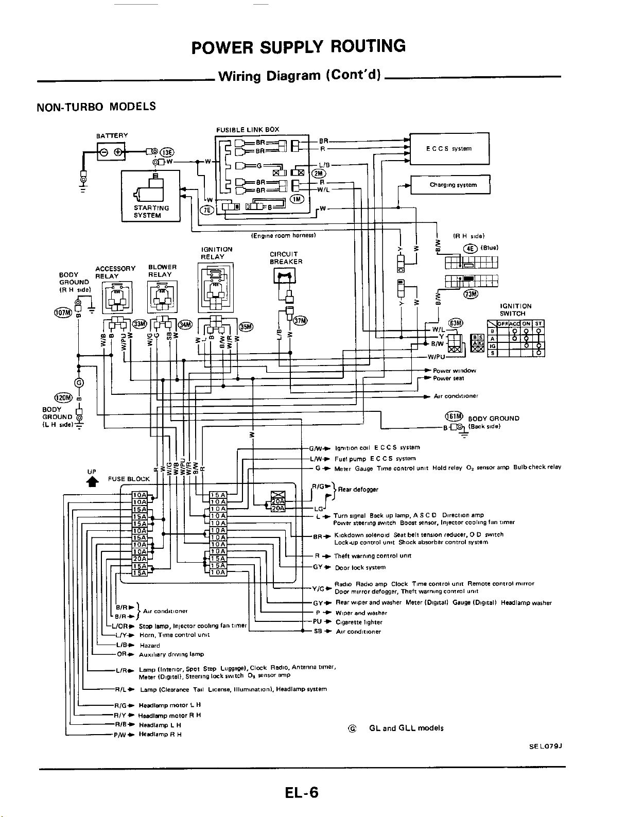
POWER SUPPLY ROUTING
Wiring
Diagram
(Cont'd)
NON-TURBO
MODELS
EL-6
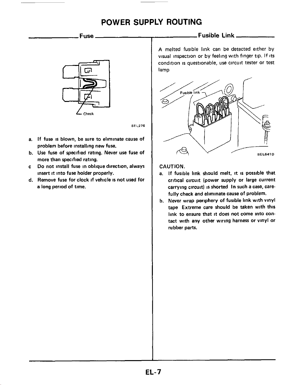
POWER SUPPLY ROUTING
Fuse
L
Check
SEl.276
a.
If
fuse
is
blown, be sure to eliminate cause of
problem before installing new fuse.
b.
Use
fuse of specified rating. Never
use
fuse of
more than specified rating.
c
Do
not install fuse in oblique direction, always
insert
it
into fuse holder properly.
d. Remove fuse for clock
if
vehicle
is
not used for
a long period
of
time.
-
Fusible
Link
A
melted fusible link can
be
detected either by
visual inspection or by feeling with finger tip.
If
Its
condition
is
questionable, use circuit tester or
test
lamp
I
SEL641D
CAUTION.
a.
If
fusible
link
should melt,
it
is
possible that
critical circuit (power supply or large current
carrying circuit)
is
shorted
In
such
a
case, care-
fully
check and eliminate
cause
of problem.
b. Never wrap periphery
of
fusible
link
with vinyl
tape Extreme care should be taken wlth
this
link to ensure
that
it
does not come into con-
tact with any other wiring harness or vinyl or
rubber parts.
EL-7
POWER SUPPLY ROUTING
Note
EL-8

BATTERY
CAUTION:
a.
If
it
becomes necessary to start the engine wlth
a
booster battery and jumper cables,
use
a
12-volt booster battery.
b. After connecting battery cables, ensure
that
they
are
tightly clamped to battery terminals for good
contact
c Never add distilled water through the hole used to check specific gravity
How
to Handle Battery
METHODS
OF
PREVENTING OVER-
DISCHARGE
The following precautions must be taken to pre-
vent over-discharging
a
battery
The battery surface (particularly
its
top)
should always be kept clean and dry
rKeep
clem
and
dry
If the top surface of
a
battery
is
wet with elec-
trolyte or water, leakage current will cause the
battery to discharge Always keep the battery
clean and dry
When the vehicle
is
not going to be used over
a
long period of time, disconnect the negative
battery terminal
(If
the
vehicle has an extend-
ed storage switch, turn
it
off
)
Remove
negative
terrnlnal
SEL712E
Check the charge condition of the battery
-
Hvdrorneier
8-
Thermal
gauge
@
Periodically check the specific gravity of the
electrolyte Keep
a
close check on charge
condition to prevent over-discharge
CHECKING ELECTROLYTE LEVEL
WARNING
Do
not allow battety fluid to come
in
contact with
skin,
eyes,
fabrics,
or
painted surfaces. After
touching a battery, do not touch
or
rub your
eyes
until
you
have thoroughly washed your hands.
If
the acid contacts the
eyes,
skin or clothing, imme-
diately
flush
with water for
15
minutes and seek
medical attention
Normally the battery does not require additional
water However, when the battery
is
used under
severe conditions, adding distilled water may be
necessary during the battery life
To
maintain serviceability,
a
perforated line has
been added to the battery caution label.
EL-9
BATTERY
How
to Handle Battery (Cont'd)
0
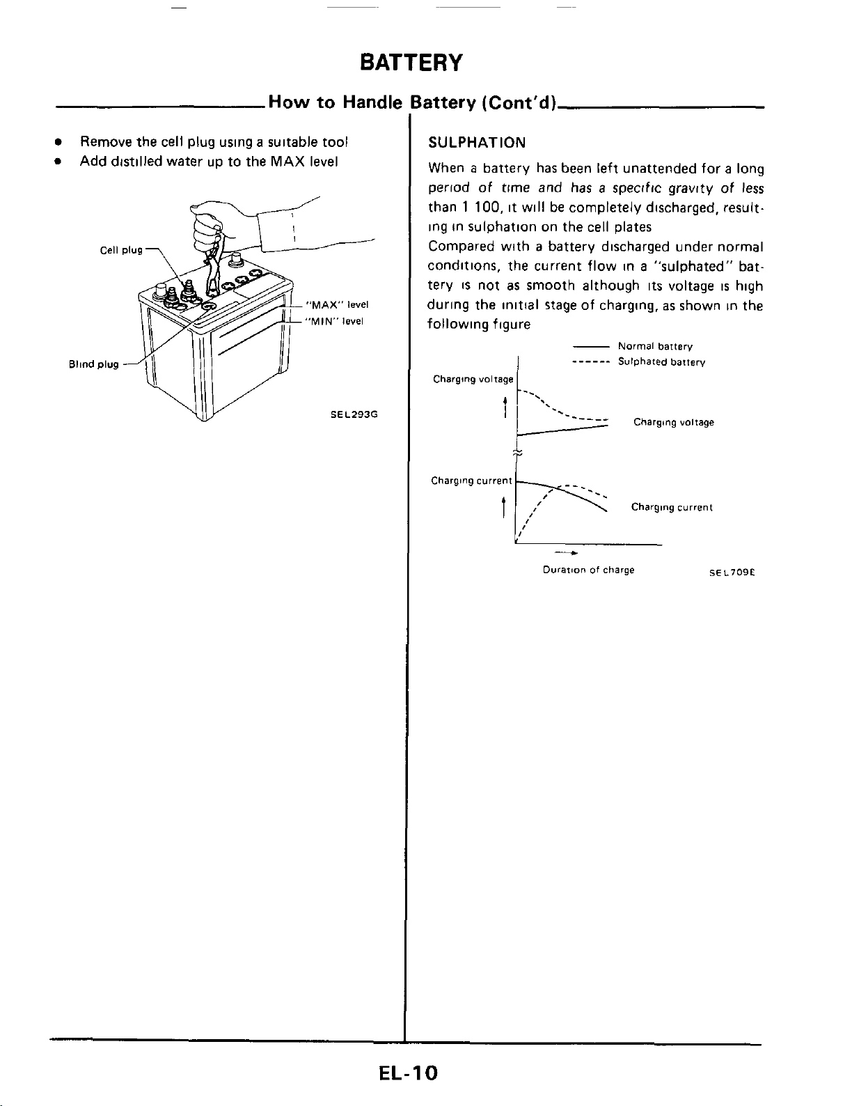
Remove the cell plug using
a
suitable tool
Add distilled water up to the MAX
level
"MAX"
level
"MIN"
level
SEL293G
SULPHATION
When
a
battery has been left unattended for
a
long
period of time and has
a
specific gravity of less
than
1
100,
it will be completely discharged, result-
ing in sulphation
on
the cell plates
Compared with
a
battery discharged under normal
conditions, the current flow in
a
"sulphated" bat-
tery
is
not
as
smooth although
its
voltage
is
high
during the initial
stage
of charging.
as
shown in the
following figure
-
Normal
battery
______
Sulphated
battery
Charging
voltage
Charging
current
Charging
current
t
-
Durarion
of
charge
SEL709E
EL-I
0
BATTERY
Specific Gravity Check
SPECIFIC
GRAVITY
CHECK
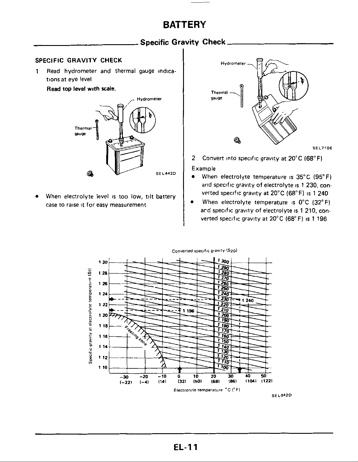
1
Read hydrometer and thermal gauge indica-
tions
at
eye level
Read
top
level
with
scale.
-
Hydrometer
SEL4d2D
When electrolyte level
IS
too low,
tilt
battery
case to raise
it
for easy measurement
Hydrometer
gauge
-U
@I
SEL710E
2
Example
Convert into specific gravlty at 20°C (68°F)
When electrolyte temperature
is
35°C
(95°F)
and speclfic gravity of electrolyte
is
1
230, con-
verted specific gravity at 20°C (68°F)
is
1
240
When electrolyte temperature
IS
0°C (32°F)
ard speciflc gravlty of electrolyte
is
1
210, con-
verted specific gravity
at
20°C (68°F)
is
1
196
Converted
specific
gravity
ISmI
1-221
1-41
1141
1321
1501
I681
1861
11041
11221
Electrolyte
temperature
'C
1'
FI
SEL042D
EL-I
1
BATTERY
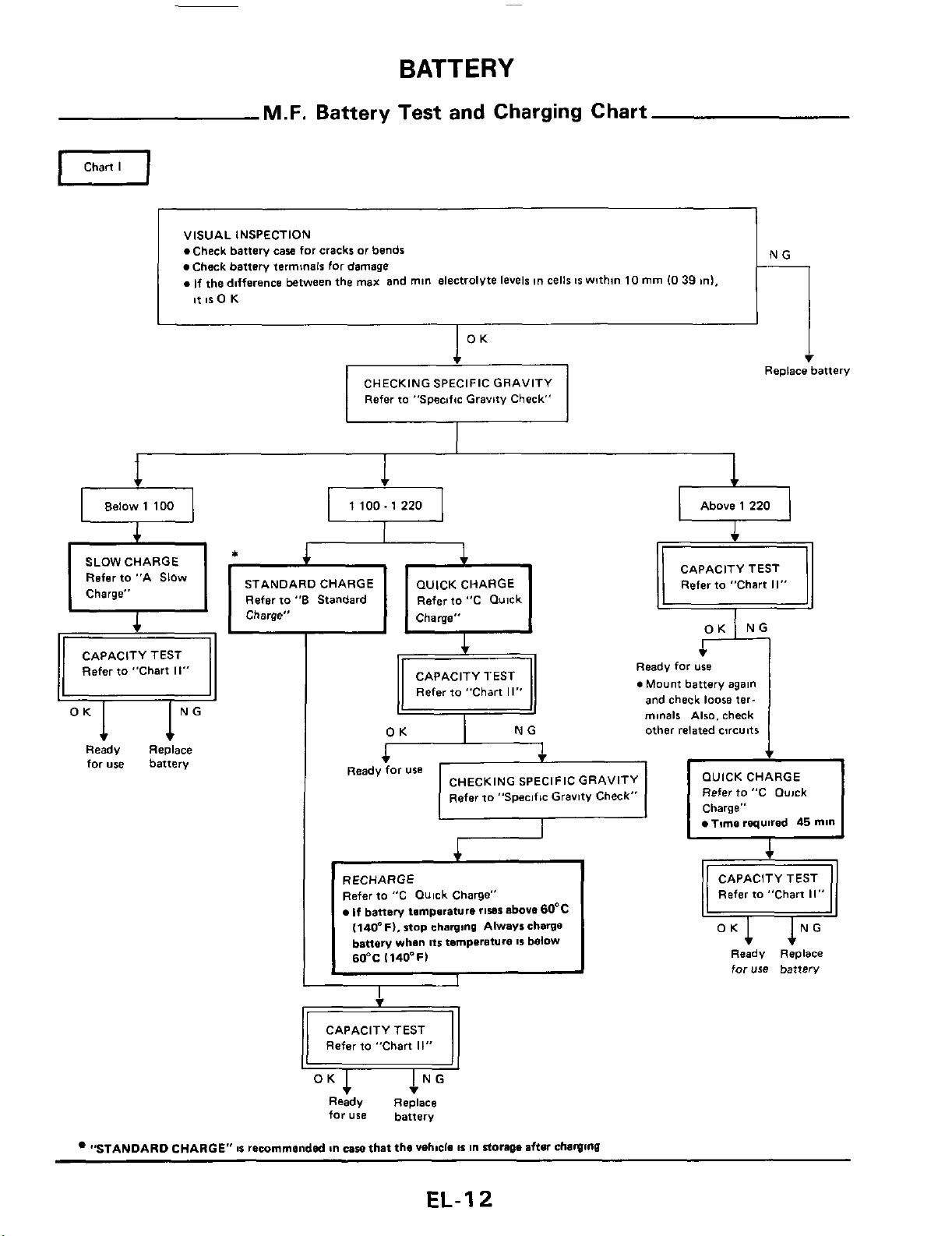
VISUAL INSPECTION
.Check battery
caw
for
cracks
or
bends
Check battery terminals for damage
.If
the dnfference between the
max
and
mln
electrolyte levels
tn
cells
IS
wnhm
10
mm
10
39
ml,
it
IS
0
K
M.F.
Battery Test and Charging Chart
0
Chart
I
NG
___
Refer
to
"Specific Gravity Check"
i
Replace battery
el
Below
1 100
a
1
100.1
220
a
Above
1
220
STANDARD CHARGE
Refar to
"6
Standard
Refer
to "C Qulck
I,
CAPACITY TEST
Refer to "Chart
11"
Ready Replace
for
use battery
iT:
CAPACITY TEST R;e
0
Mount for; battery again
I
,
Refer to "Chart
II"
and check
loose
ter-
minals
Also. check
other related circuits
OUICK CHARGE
Refer
to
"C Ouick
Charge"
Time
required
45
mln
Ready
for
use
CHECKING SPECIFIC GRAVITY
Refer to "Specific Gravitv Check"
RECHARGE
Refer to "C Quick Charge"
If
battery tmmpsrature
rises
above 60°C
(140"Fl.
stop
charging
Always charge
battery
whan
Its
temperature
IS
below
60°C
1140-F)
CAPACITY TEST
Refer to "Chart
11"
Ready Replace
for
use
battery
"STANDARD CHARGE"
8%
remrnmandsd
&n
caw
that the
vehicle
IS
in
storage
afisr
chawmu
Refer to "Chart
II"
Ready
Replace
for
use
battery
EL-I
2
BATTERY
M.F.
Battery Test and Charging Chart (Cont'd)
OK
Below 1 150 1 150.1 200
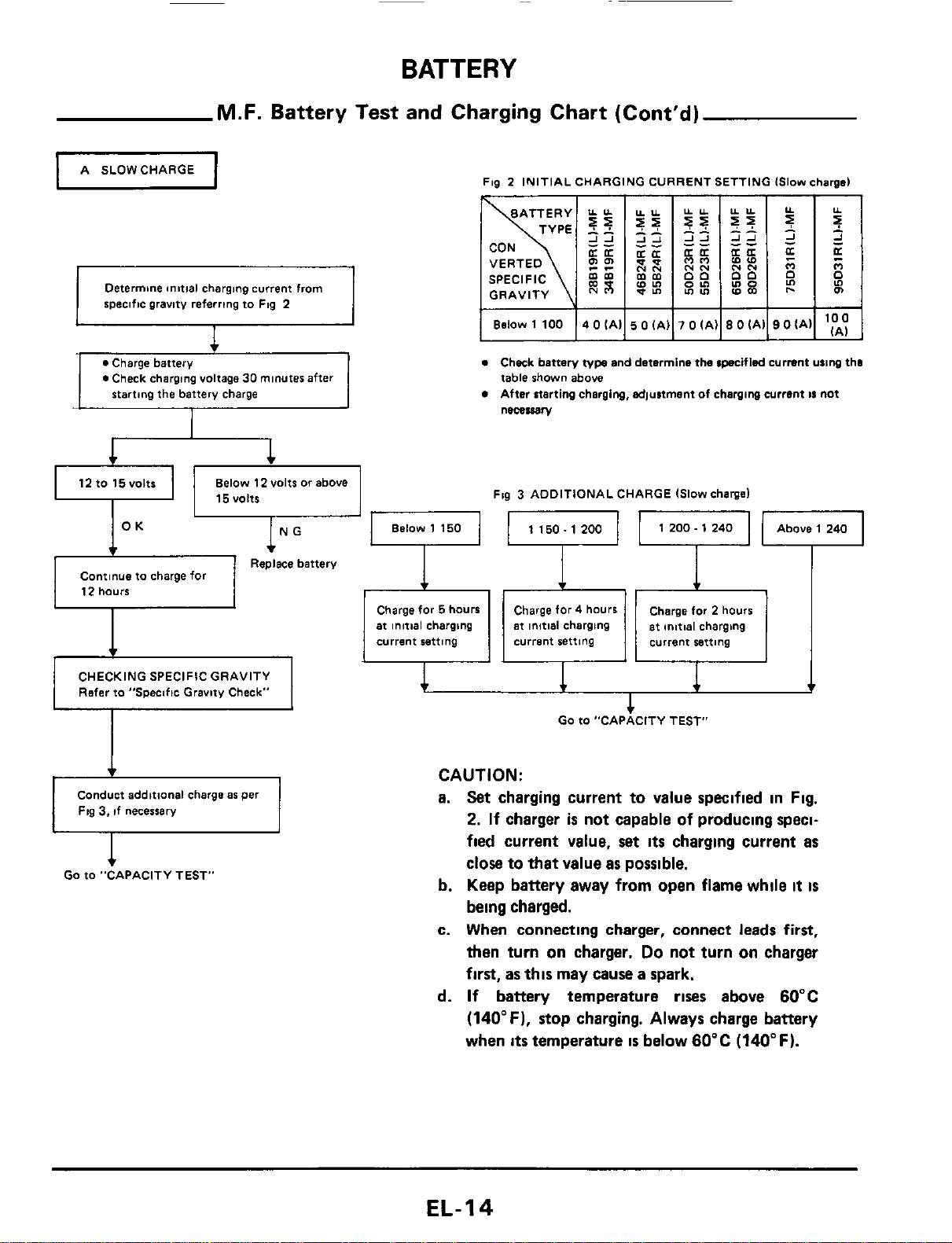
A SLOWCHARGE
U
Above 1 240
1 200
-
1 240
Fia
2
INITIAL CHARGING CURRENT SETTING 1Slow chard
Replace battery
Continue to charge for
12 hours
I
I
I
1
Charge for
5
hours Charge for
4
hours
at
initial chargbng
at
initial charging at initial charging
current setting current setting current retting
I
Charge for 2 hours
CHECKING SPECIFIC GRAVITY
I
1
Refer
to "Specific Gravity Check"
I
Determine anttial charging current from
specific gravity referring to Flg 2
1
1
1
v
I
0
Check charging voltage
30
minutes after
12tO15VOltt
Below 12 volts
or
above
u
I
15VOltS
I
I
I
I
I
Below 1 100
14
0
(All
5
0
IAI]
7
0
lAIl8
0
iAll9 OiAll
'E
e
Check battery
type
and determine the cpecifled current u11ng tho
table shown above
After atarting charging, adjustment of charging current
11
not
necessary
Fig
3
ADDITIONAL CHARGE Islow chargel
Conduct additional charge
a6
per
Fig
3,
if necessary
1
GO
to -CAPACITY
TES~
CAUTION:
a.
Set
charging
current
to
value
specified
in
Fig.
2.
If
charger
is
not
capable
of
producing
speci-
fied
current
value,
set
its
charging
current
as
close
to
that
value
as
possible.
b.
Keep
battery
away
from
open
flame
while
it
is
being
charged.
c.
When
connecting
charger,
connect
leads
first,
then
turn
on
charger.
Do
not
turn
on
charger
first,
as
this
may
cause
a
spark.
d.
If
battery
temperature
rises
above
60°C
(140°F).
stop
charging.
Always
charge
battery
when
its
temperature
is
below
60°C
(140°F).
EL-I4
BATTERY
M.F.
Battery Test and Charging Chart (Cont'd)
I
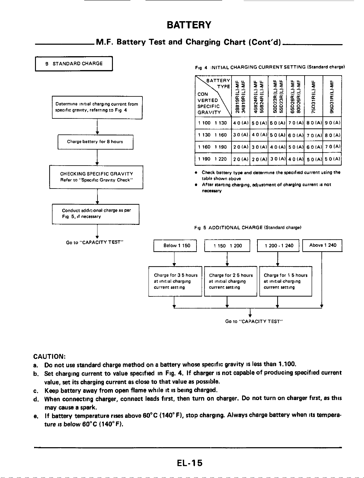
8
STANDARDCHARGE
I
Determine
initial
charging
current
from
specific
gravity,
referring
to
Fig
4
Charge
battery
for
8
hours
CHECKING
SPECIFIC
GRAVITY
Refer
to
"Specific
Gravity
Check"
I
I
I
Ftg
4
INITIAL
CHARGING
CURRENT SETTING IStandard charge)
SPECIFIC
mm
GRAVITY
0
Chwk
battery
tyw
and
determine
the
specified
Current
using
the
tablo
shown
above
After
starting
charging.
adjustment
of
charging
current
is
not
necessary
Conduct
additional
charge
as
per
Fig
5,
if
necessarv
Fig
5
ADDITIONAL
CHARGE
IStandard
charge)
Go
to
"CAPACITY TEST"
1
200.
1
240
at
initial
charging
current
setting
current
retting
at
initial
charging
Go
to
"CAPACITY TEST"
CAUTION:
a.
Do
not
use standard
charge
method
on
a
battery
whose
specific
gravity
IS
less
than
1.100.
b.
Set
charging
current
to
value
specified
in
Fig.
4.
If
charger
is
not
capable
of
producing
specified
current
value,
set
its
charging
current
as
close
to
that
value
as
possible.
c.
Keep
battery
away
from
open
flame
while
it
is
being
chargd.
d.
When
connecting
charger,
connect
leads
first,
then
turn
on
charger.
Do
not
turn
on
charger
first,
as
this
may
cause
a
spark.
e.
If
battery
temperature
rises
above
60°C
(140"
F),
stop
charging.
Always
charge
battery
when
its
tempera-
ture
IS
below60'C
(140°F).
EL-I
5
BATTERY
M.F.
Battery Test and Charging Chart (Cont'd)
GRAVITY
lOlAl
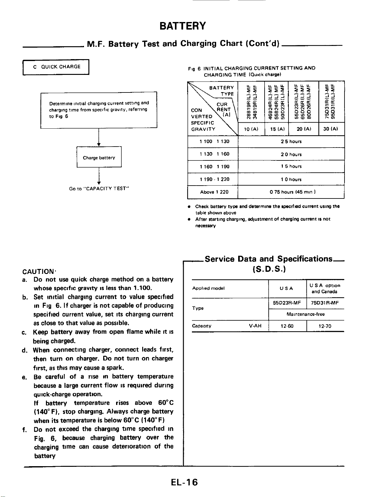
C
WICK
CHARGE
u
151Al
20IAI 30(Al
Determine
initial charging
current
setting
and
charging
time
from
specific
gravity,
referring
to
Fig
6
Charge
battery
1100
1130
1
2
5
hours
Go
to
"CAPACITY
TEST"
Capacity
V-AH
CAUTION.
a.
Do
not
use
quick charge method on a battery
whose specific gravity
is
less
than
1.100.
b.
Set
initial
charging current to value specified
in
Fig
6.
If
charger
is
not capable of producing
specified current value, set
its
charging current
as
close to that value
as
possible.
c. Keep battery away from open flame while
it
is
being charged.
d. When connecting charger, connect leads
first,
then
turn
on charger.
Do
not turn on charger
first,
as
this
may cause a spark.
e.
Be
careful
of
a rise
in
battery temperature
because
a
large current flow
IS
required
during
qu
ick-charge operation.
If
battery temperature rises above 60°C
(140°F). stop charging. Always charge battery
when
its
temperature
is
below 60°C (140°F)
Do
not exceed
the
charging time specified
in
Fig,
6,
because
charging battery over the
charging time can cause deterioratlon of the
battery
f.
12-60
12-70
Fqg
6
INITIAL
CHARGING CURRENT
SETTING
AND
CHARGING
TIME
IQutck
chargel
I
1130
1160
I
2
0
hours
I
I
I
1160
1190
I
1
5
hours
11190-12201
1
0
hours
I
I
I
Above
1220
I
0
75
hours
145
man
1
Check
battery
typs
and
determine
the
lpsclfled
current
using
thtl
table
shown
above
After
starting
charging,
6d)unment
of
charging
current
11
not
nemuBry
-Service Data and Specifications-
(S.
D.
S.)
Applied
model
U
SA
option
I I
and
Canada
Maintenancefree
EL-1
6
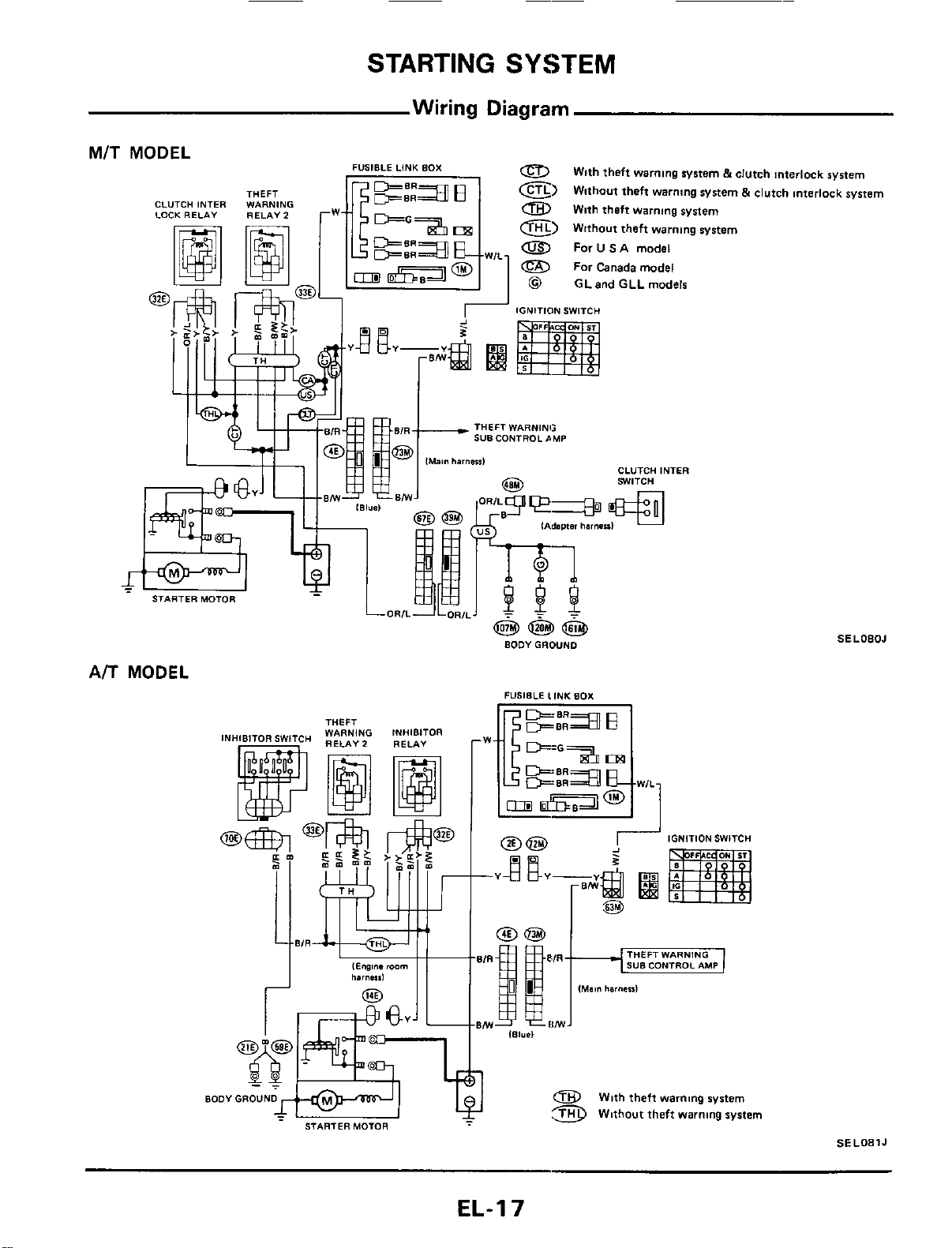
STARTING
SYSTEM
Wiring Diagram
MIT
MODEL
THEFT
CLUTCH INTER WARNING
LOCK
RELAY
RELAY
2
0
E)
a
With theft
warning
system
e)
Without theft
warning
system
0
For
U
SA
model
For
Canada
model
With theft
warning
system
5
clutch Interlock system
Without theft warning system
5
clutch Interlock system
FUSIBLE LINK BOX
@
GLand
GLL
models
THEFT WARNING
sua
CONTROL
~MP
CLUTCH INTER
SWITCH
A/T
MODEL
TUFF,
aoov
GROUND
STARTER MOTOR
BODYGROUND
IGNITION SWITCH
@@
4L"Q
2
pg
--Y
am
@$
(Main
harneul
SELOBOJ
0
With theft
warnmg
system
Without theft warning system
SE
LO81
J
EL-I
7
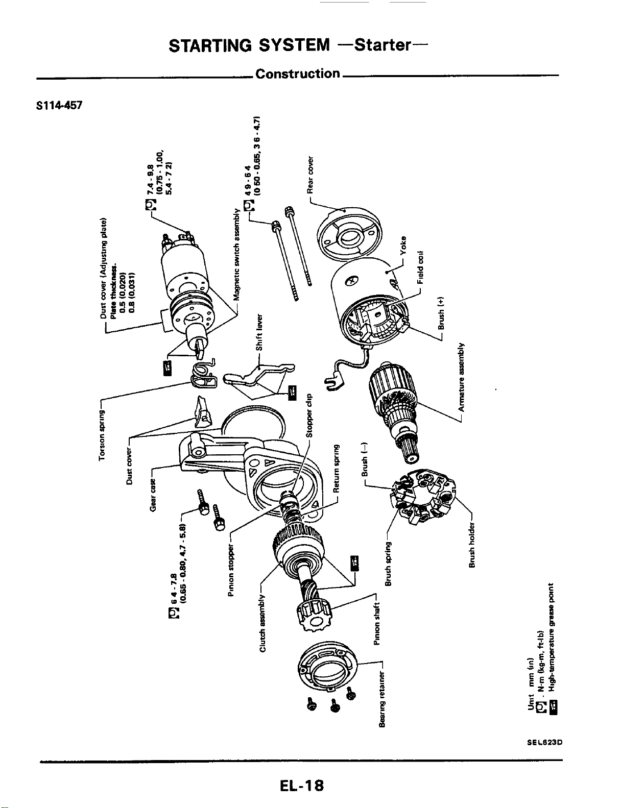
STARTING SYSTEM
-Starter-
Construction
S114-457
-
I.
d
(D
n
SELBZJD
EL-1
8
STARTING
SYSTEM
-Starter-
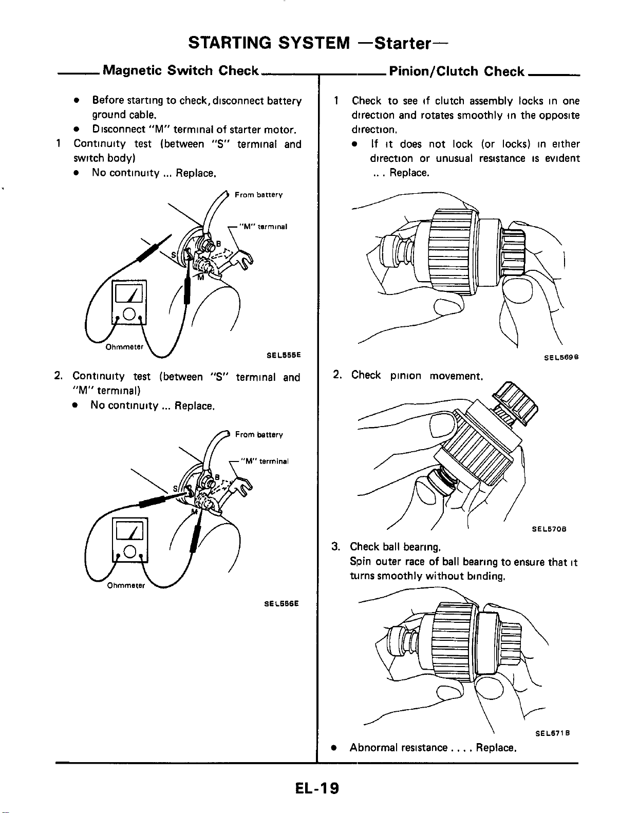
Magnetic Switch Check
switch body)
No
continuity
...
Replace.
Before starting to check, disconnect battery
ground cable.
Disconnect
"M"
terminal of starter motor.
1
Continuity
test
(between
"S"
terminal and
From
battery
tnrminal
SEL666E
2.
Continuity
test
(between
"S"
terminal and
"M"
terminal)
No
continuity
...
Replace.
fl
Frombattsry
SEL666E
--
Pinion/Clutch Check
1
Check to
see
if clutch assembly locks in one
direction and rotates smoothly in the opposite
direction.
If
it
does not lock (or locks) in either
direction or unusual resistance
is
evident
..
.
Replace.
SEL569B
I
SEL670B
3.
Check ball bearing.
Spin outer race
of
ball bearing to ensure that
it
turns smoothly without binding.
\
SEL671B
Abnormal resistance.
,
.
.
Replace.
EL-19
STARTING
SYSTEM
-Starter-
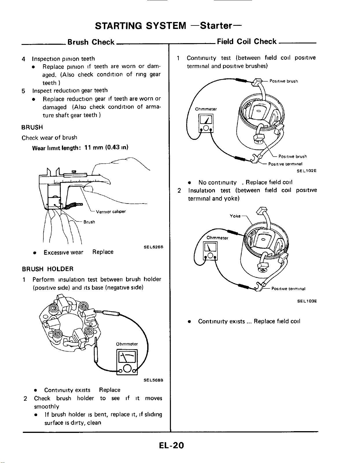
Brush Check
4
Inspection pinion teeth
a
Replace pinion
if
teeth are worn or dam-
aged. (Also check condition of ring gear
teeth
)
Replace reduction gear
if
teeth are worn or
damaged (Also check condition of arma-
ture shaft gear teeth
)
5
Inspect reduction gear teeth
a
BRUSH
Check wear of brush
Wear limit
length:
11
rnm
(0.43
in)
SEL6268
Excessive
wear
Replace
BRUSH HOLDER
1
Perform insulation
test
between brush holder
(positive side) and
its
base (negative side)
SEL5688
a
Continuity exists Replace
smoothly
a
2
Check brush holder to
see
if
it
moves
If brush holder
is
bent, replace
it,
if sliding
surface
is
dirty, clean
Field Coil Check
1
Continuity
test
(between field coil positive
terminal and positive brushes)
Paritwe brush
/-----%
SEL102E
a
No
continuity
.
Replace field coil
terminal and yoke)
2
Insulation
test
(between field cod positive
Yoke-,
SE
L
103E
a
Continuity exists
...
Replace field coil
EL-20
STARTING
SYSTEM
-Starter-
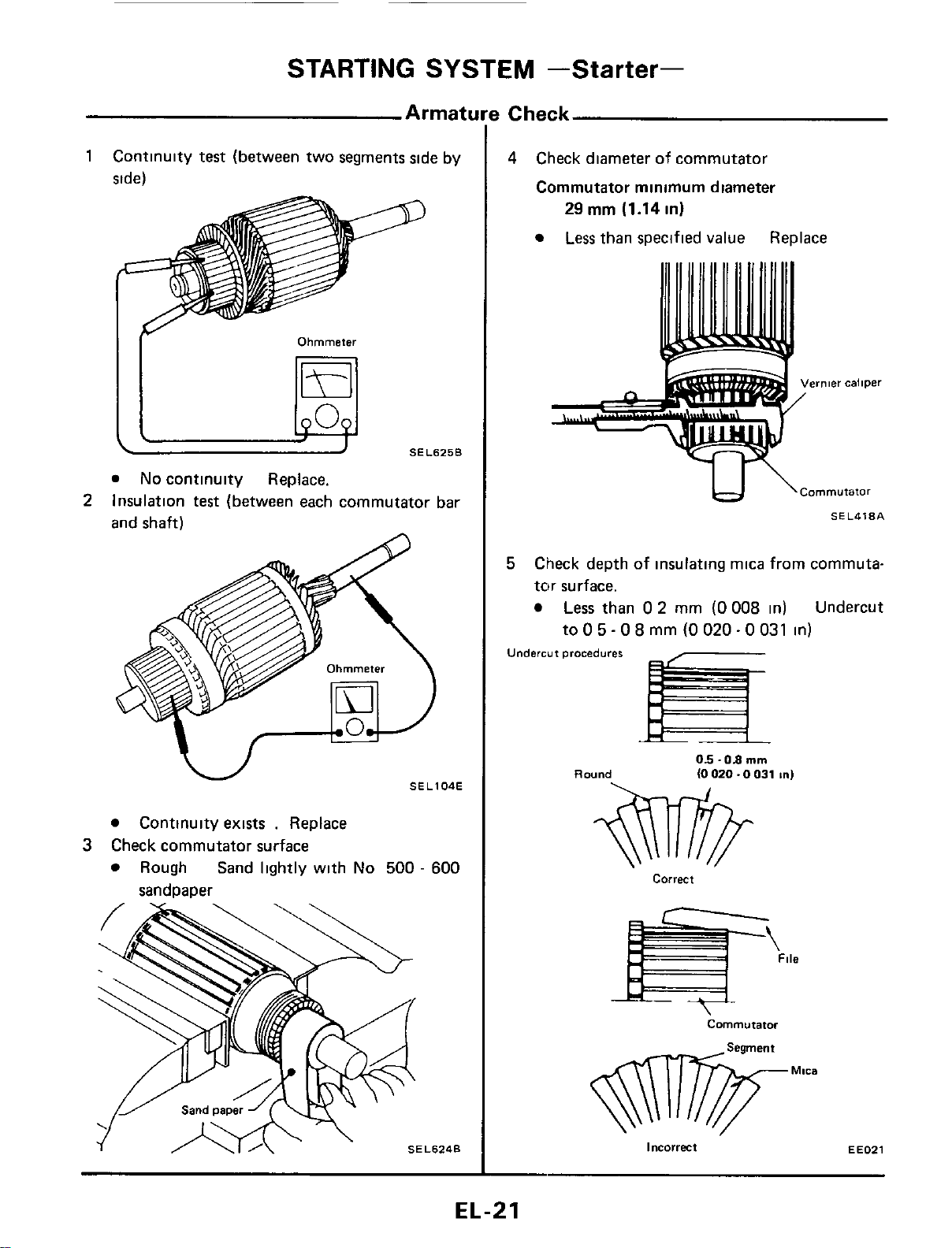
1
Continuity
test
(between two segments side by
side)
Ohmmeter
SEL625B
I[
@
No
continuity Replace.
Insulation
test
(between each commutator bar
and shaft)
2
Continuity exists
.
Replace
Rough Sand lightly with
No
500
-
600
3
Check commutator surface
sandoaoer
!
Check
4
Check diameter
of
commutator
Commutator minimum diameter
29
rnm (1.14 in)
Less
than specified value Replace
IJ
\Cornmutator
SEL418A
5
Check depth of insulating mica from commuta-
tnr surface.
Less
than
0
2
mm
(0 008
in) Undercut
to
0
5
-
0
8
mm
(0
020
-
0
031
in)
Undercut
procedures
Round
05
-08
mm
(0
020.0
031
In)
correct
Commutator
incorrect
EE021
EL-21
____
STARTING
SYSTEM
-Starter-
Applied model
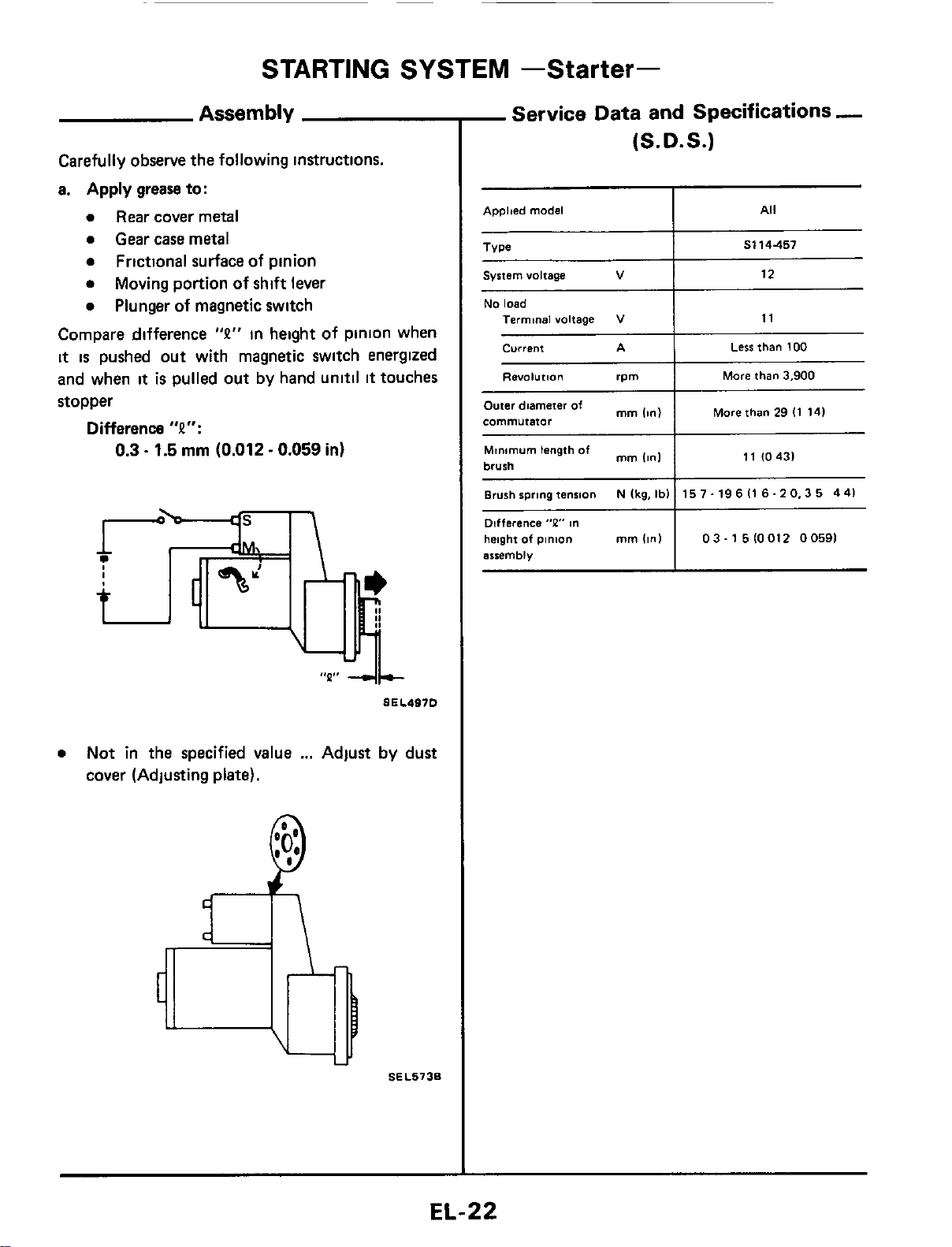
Assembly
All
Carefully observe the following instructions.
a.
Apply
grease to:
0
Rear
cover metal
0
Gear case metal
0
Frictional surface of pinion
0
0
Plunger
of
magnetic switch
Moving portion of shift lever
Compare difference
"P"
in height of pinion when
it
is
pushed out with magnetic switch energized
and when
it
is
pulled out by hand unitil
it
touches
stopper
Difference
"P":
0.3
-
1.5
rnrn
(0.012
-
0.059
in)
~~~
Type
0
Not in the specified value
...
Adjust by dust
cover (Adjusting
plate).
S114457
SEL5736
System voltage
V
-
Service
Data and Specifications
-
(S.D.S.)
12
Minimum length
of
brush
Brush spring tension
Difference
"P"
m
height
of
pinion
mm
(in)
arremblv
mm
Iinl
N
Ikg,
Ibl
11
10431
15
7.
19
6
I1
6.2
0,3
5
4
41
03-15lOOl2
00591
No
load
Termtnal voltage
current
Less
than
100
RWOl"tl.3"
rpm
More
than
3,900
I
More than
29
I1
141
Outer diameter
of
mm
commutator
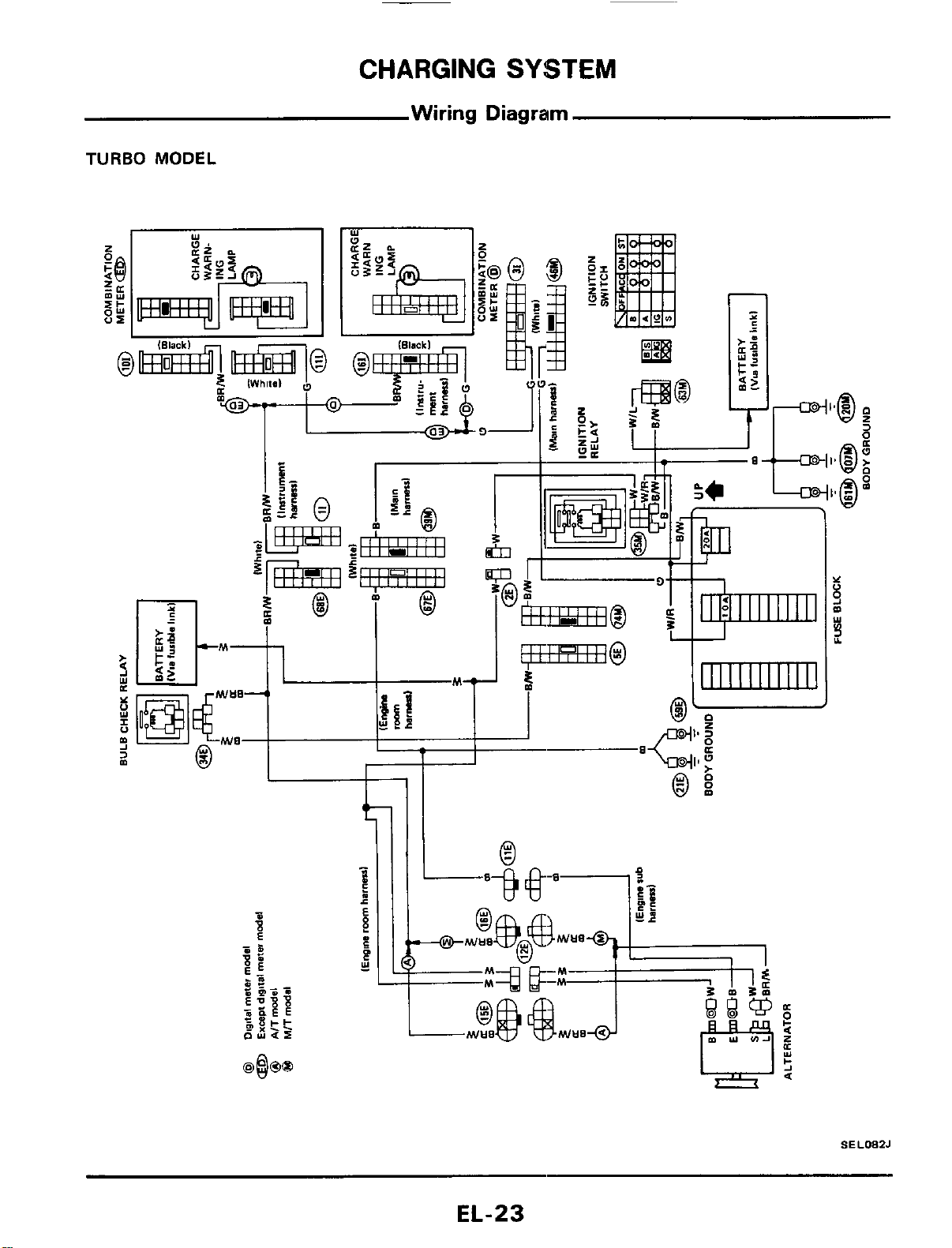
CHARGING
SYSTEM
Wiring Diagram
TURBO
MODEL
I_
'
SELOEZJ
EL-23
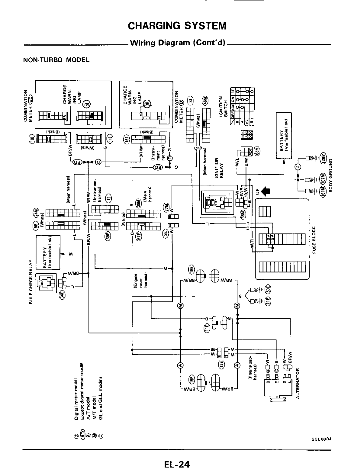
CHARGING
SYSTEM
Wiring Diagram (Cont'd)
NON-TURBO MODEL
I
I
T
SEL083J
EL-24
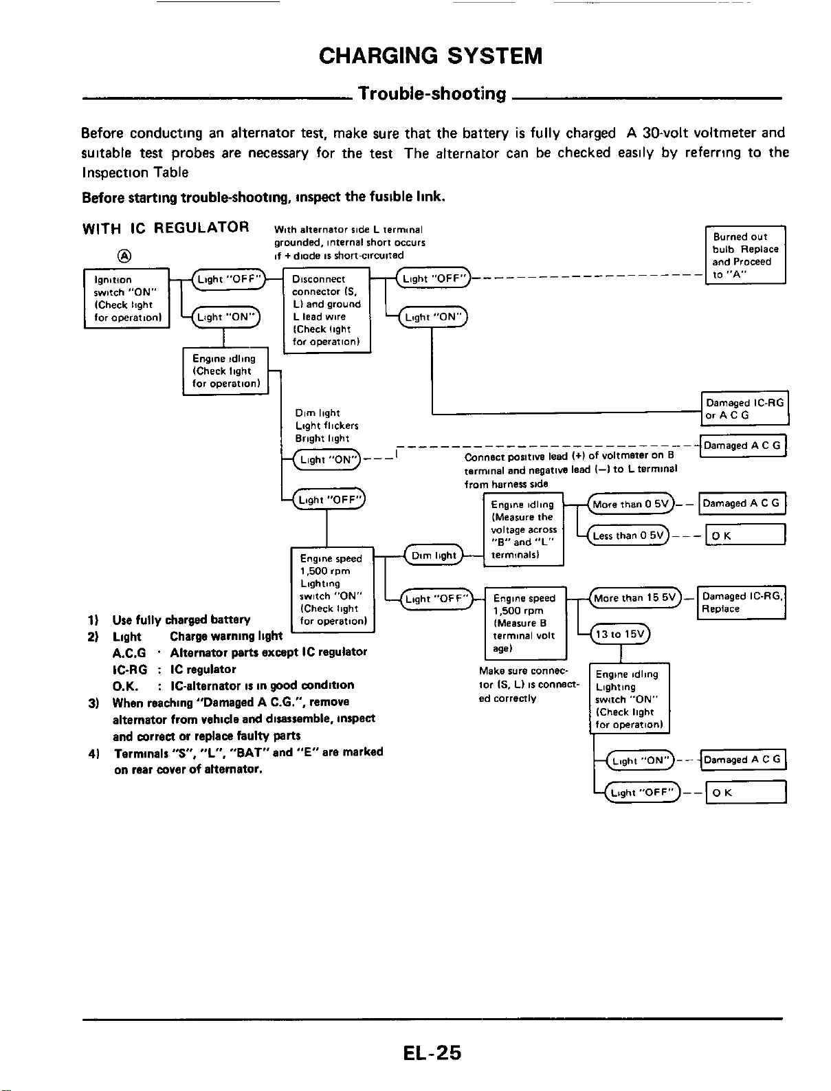
CHARGING
SYSTEM
lgnltlo"
switch "ON"
ICheck
light
for
opeerat,onI
Trouble-shooting
Before conducting an alternator
test,
make sure
that
the battery
is
fully charged
A
30-volt voltmeter
and
suitable
test
probes are necessary for the test The alternator can be checked easily by referring to the
Inspection Table
Before
starting trouble-shooting,
inspect
the fusible
link.
_________------------
connector
IS.
Ll and
ground
L lead
wire
from
harness
ride
(Measure
the
voltage
across
"E"
and
"L"
Engine
speed
1,500
rpm
Lighting
switch
"ON"
(Check
Ibght
1)
Use
fully charged battery
for
operation1
2)
Light Charge warning light
A.C.G
.
Alternator
parts
except IC regulator
IC-RG
:
IC regulator
O.K.
:
IC-alternator
is
in
good
wndition
3)
When reaching "Damaged A C.6.". remove
alternator from vehicle
and
disassemble, inspea
and mrrea
or
replace faulty
parts
Termlnalr
"S",
"L",
"BAT" and
"E"
are marked
on rear wver
of
alternator.
4)
EL-25
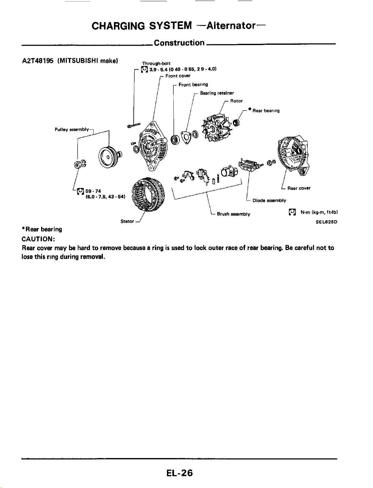
CHARGING
SYSTEM
-Alternator-
Construction
AZT48195 (MITSUBISHI make)
Through.bolt
(ol
3.9.5.4
10
40
.
0
55,
2
9
.4.01
Fmnt
cover
Front bearing
Bearing retainer
Rotor
/
r
Rear bearing
l
-/
I
L
Rear cover
v
Diode
assembly
Brush araembly
(ol
Nm
Ikg-m.
ft4bl
Stator
J
SEL626D
*Rear bearing
CAUTION:
Rear cover
may
be hard to remove because a ring
is
used to lock outer race
of
rear bearing. Be careful not to
lose this ring during removal.
EL-26
CHARGING
SYSTEM
--Alternator-
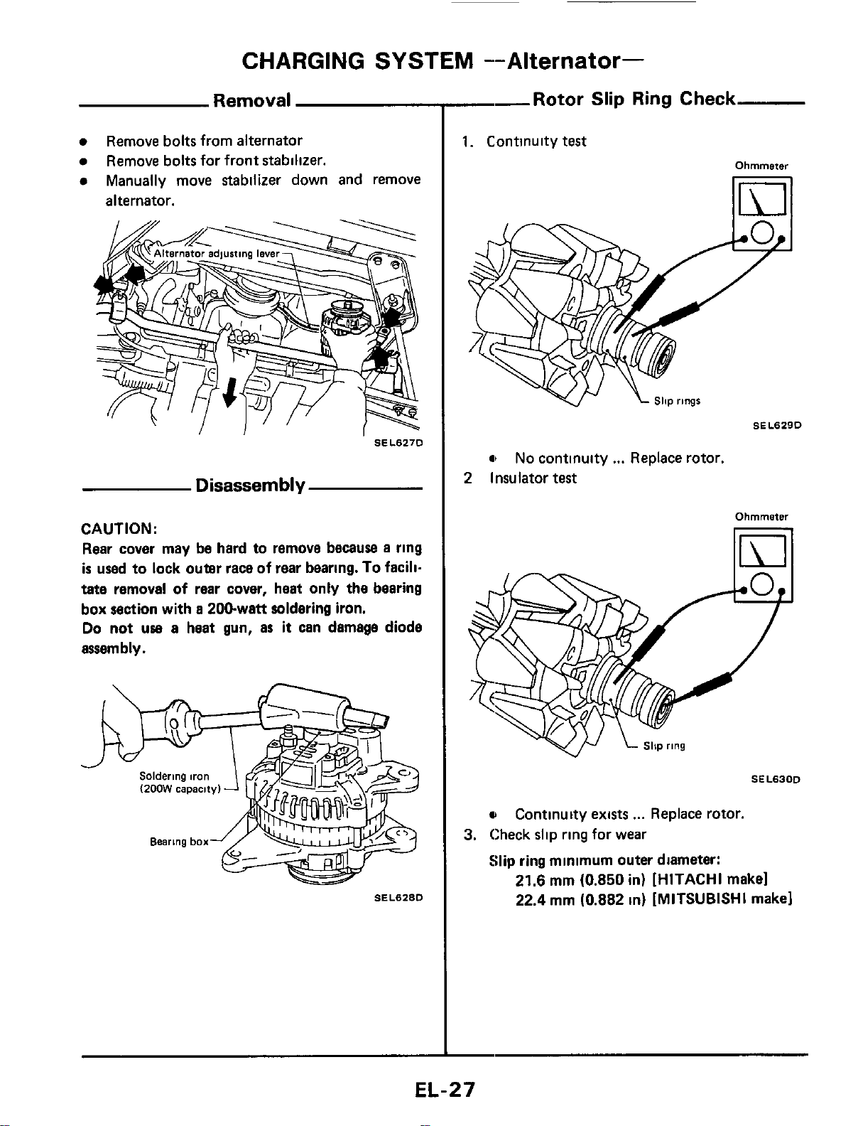
Removal
Remove bolts from alternator
Manually move stabilizer down and remove
Remove bolts for front stabilizer.
alternator.
SEL627D
Disassembly
CAUTION:
Rear cover may be hard to remove because
a
ring
is
used to lock outer race of
rear
bearing.
To
facili-
tate removal of rear cover, heat only the bearing
box section with
a
200-watt soldering iron.
Do not
uae
a
heat gun,
as
it
can damage diode
assembly.
SEL628D
--Rotor
Slip Ring Check
1.
Continuity
test
Ohmmeter
11111
a
No continuity
...
Replace rotor.
2
Insulator
test
Ohmmeter
SEL63OD
u
3.
Check slip ring for wear
Slip ring minimum outer diameter:
Continuity exists
...
Replace rotor.
21.6
mm (0.850 in)
[HITACHI
make1
22.4 mm (0.882 in)
[MITSUBISHI
make1
EL-27
CHARGING
SYSTEM
-Alternator-
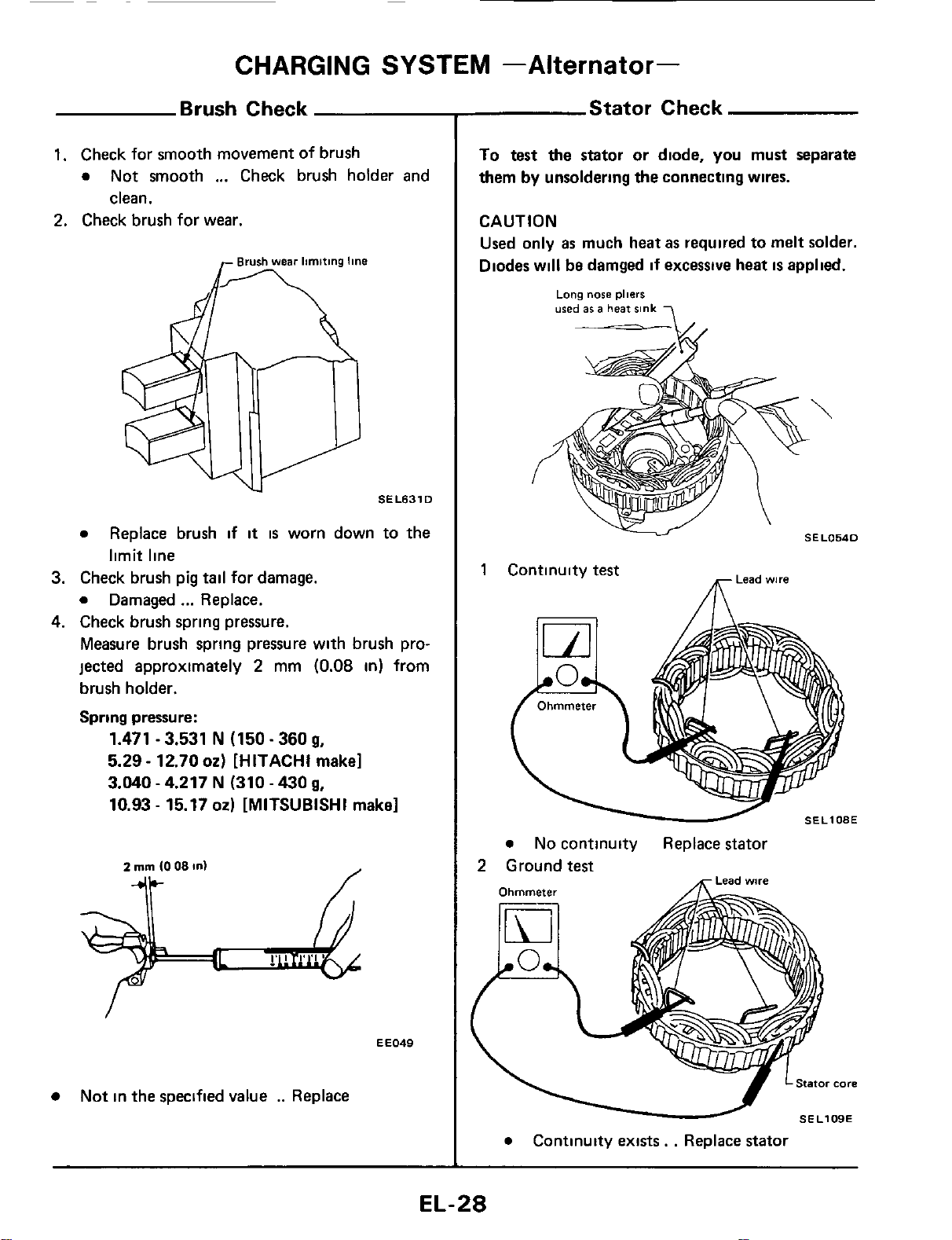
Brush Check
1.
Check for smooth movement
of
brush
0
Not smooth
...
Check brush holder and
clean.
2.
Check brush for wear.
SEL631
D
0
3.
Check brush pig
tail
for damage.
0
Damaged
...
Replace.
4.
Check brush spring pressure.
Measure brush spring pressure with brush pro-
jected approximately
2
mm
(0.08
in)
from
brush holder.
Spring pressure:
Replace brush if
it
is
worn down to the
limit line
1.471
-
3.531
N
(150.360
g,
5.29
-
12.70
02)
[HITACHI make]
3.040
-
4.217
N
(310
-
430
g,
10.93
-
15.17
02)
[MITSUBISHI make]
EE049
Not in the specified value
..
Replace
Stator Check
To test the stator or diode,
you
must separate
them
by
unsoldering the connecting wires.
CAUTION
Used only
as
much heat
as
required to melt solder.
Diodes will
be
damged
if
excessive heat
is
applied.
Long
nose
pliers
used
86
a
heat
sink
-
-A/.
Lead
wire
1
Continuity
test
m
SEL108E
0
No continuity Replace stator
2
Ground
test
0
Continuity exists.
.
Replace stator
EL-28

CHARGING
SYSTEM
--Alternator-
Diode
Check
DIODE
Use
an ohmmeter to check condition
of
diodes as indicated in chart below
If any
of
the test results
is
not satisfactory, replace diode iissembly
Ohmmeter probes
Continuity
Negative
0
Diode terminals
Positive diode plate
Positive
0
Positive diode plate
Diode terminals
Diodes check (Positive side)
Diode terminals No
Diode terminals Negative diode plate Yes
Diodes check (Negative side)
Negative
diode
plate
\
-
plate
Sub
diode
SEL767D
Su
bdiode
Attach ohmmeters' probe to each end
of
diode
and check for continuity.
SELLltOA
e
Continuity
is
N.G.
. .
Replace diode assembly
EL-29
~
CHARGING
SYSTEM
-Alternator-
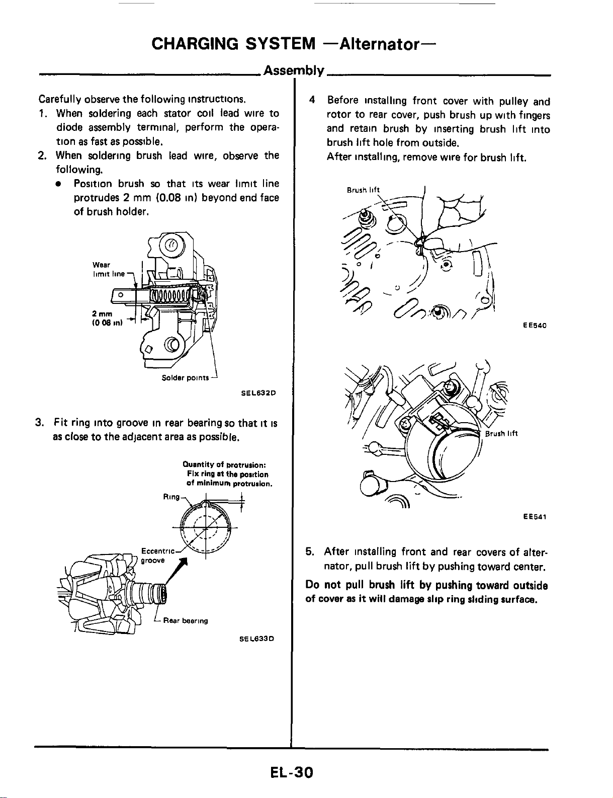
Carefully observe
the
following instructions.
1.
When soldering each stator coil lead wire to
diode assembly terminal, perform the opera-
tion
as
fast
as
possible.
2.
When soldering brush lead wire, observe the
following.
Position brush
so
that
its
wear limit line
protrudes
2
mm
(0.08
in)
beyond end face
of brush holder.
Solder
points
SEL632D
3.
Fit ring into groove in
rear
bearing
so
that
it
is
as close to the adjacent
area
as possible.
Quantity
of
brotrurion:
Fix
ring
at
the
position
of
minimum
protrusion.
4
Before installing front cover with pulley
and
rotor to
rear
cover, push brush up with fingers
and retain brush by inserting brush
lift
into
brush
lift
hole from outside.
After installing, remove wire for brush
lift.
EE540
EE541
5.
After installing front and rear covers of
alter-
nator, pull brush
lift
by pushing toward center.
Do
not pull
brush
lift
by
pushing toward outside
of cover
as
it
will
damage
slip
ring
sliding
surface.
EL-30
CHARGING
SYSTEM
--Alternator-
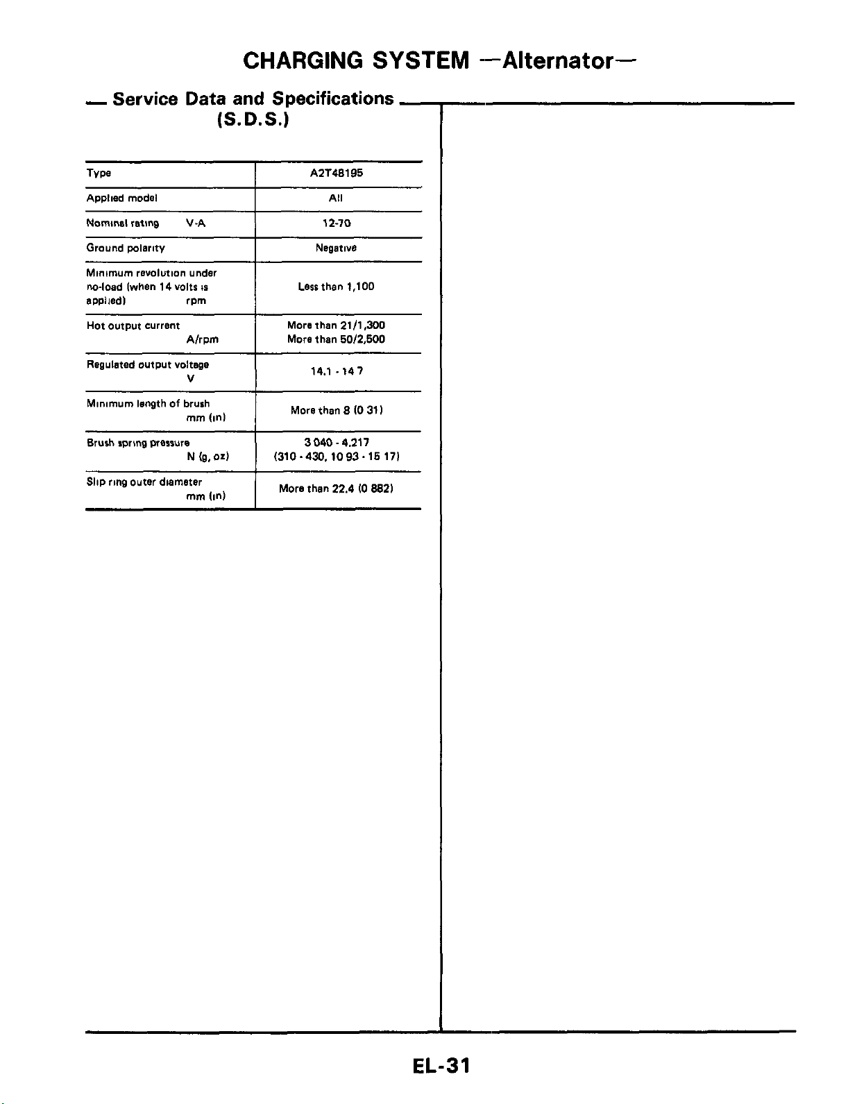
Regulated output voltage
V
Minimum length
of
brush
mm
(In1
Brush rpnng wesrure
N
(g.04
Slip ring outer diameter
mrn
(in)
-
Service
Data and
Specifications
-
(S.D.S.)
14.1 .141
More than
8
(0
31
I
3040.4.211
(310-430.1093~16171
More than
22.4
IO
8821
AZT48195
Applied model
Nominal
reting
V-A 12-10
Ground wlerity
I
Negative
Minimum
revolution under
m-load (when
14
volts
IS
ewliedl rpm
I
Lesrthen
1,100
Hot output current
I
More than
21/1.300
A/rpm
More then
60/2.600
EL-31
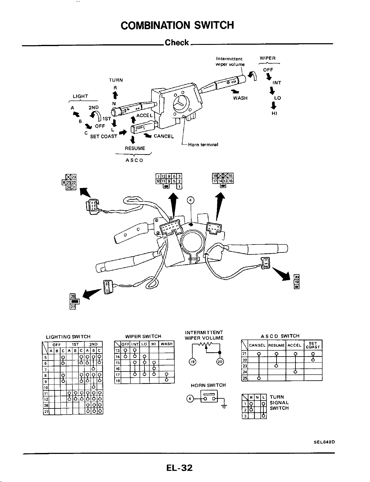
COMBINATION
SWITCH
TURN
LIGHT
i
-
%I
Intermittent
wiper
volume
O?
WASH
1
ST
OFF
-
SET COAST
4-a
L
v
'
CANCEL
LHom terminal
RESUME
ASCD
WIPER
OFF
-
I
NT
s
4
4
LO
HI
WIPER SWITCH
INTERMITTENT
WIPER VOLUME
HORN SWITCH
ASCD SWITCH
TURN
SIGNAL
SWITCH
SEL642D
EL-32
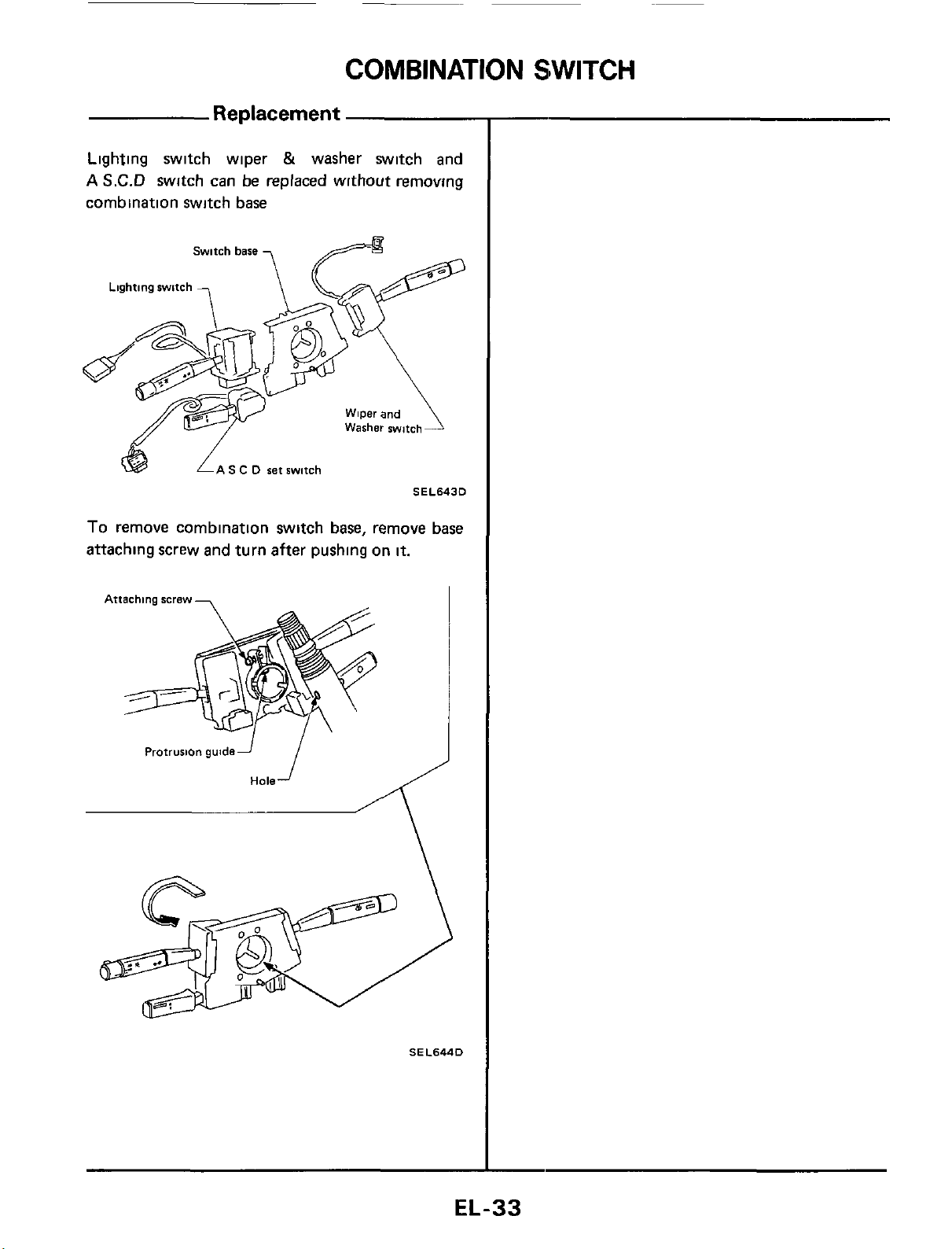
COMBINATION
SWITCH
Replacement
Lighting switch wiper
&
washer switch and
A
S.C.D
switch can be replaced without removing
combination switch base
S
C
D
set switch
SEL6430
To remove combination switch base, remove base
attaching screw and turn after pushing on
it.
Attaching screw
-
i
Protrusion guidei
Hole
SEL644D
EL-33
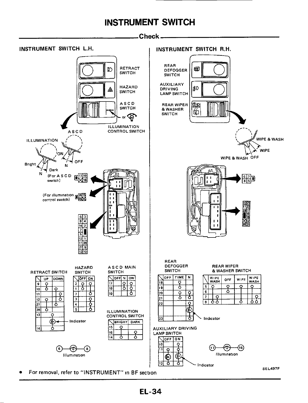
INSTRUMENT
SWITCH
Check
INSTRUMENT SWITCH L.H.
RETRACT
SWITCH
HAZARD
SWITCH
ASCD CONTROL SWITCH
/--.
ILLUMINATION
OFF
Bright N
Dark
IForASCD
@
IWI
tch
1
(For illumination
control
switch)
RETRACT SWITCH
HAZARD
SWITCH
Indicator
@-@-@
Illumination
ASCD MAIN
SWITCH
ILLUMINATION
CONTROL SWITCH
INSTRUMENT SWITCH R.H.
-
REAR
DEFOGGER
SWITCH
AUXILIARY
DRIVING
LAMP SWITCH
REAR WIPER
&WASHER
SWITCH
REAR
DEFOGGER REAR WIPER
SWITCH
~
&WASHER SWITCH
.
lndicatoi
AUXILIARY DRIVING
LAMP SWITCH
@-@---@
Illumination
Indicator
SEL497F
For removal, refer
to
"INSTRUMENT"
in
BF section
EL-34
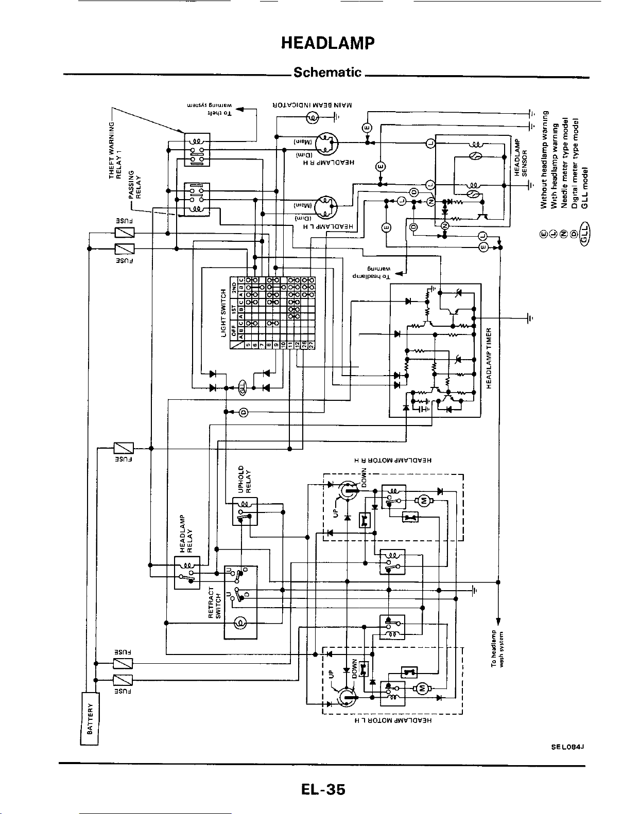
HEADLAMP
Schematic:
H
tl
tlOIOWdWVlOV3H
1
I
I
I
I
I
I
J
~
-II’
L
_______--____--____
J
H
1
UOLOW
dWVlOW’3H
SEL084J
EL-35
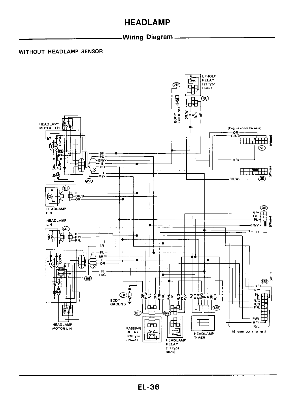
HEADLAMP
Wiring
Diagram
WITHOUT
HEADLAMP
SENSOR
..,..
IEngine
room
harnersl
IlTfype
Black)
EL-36
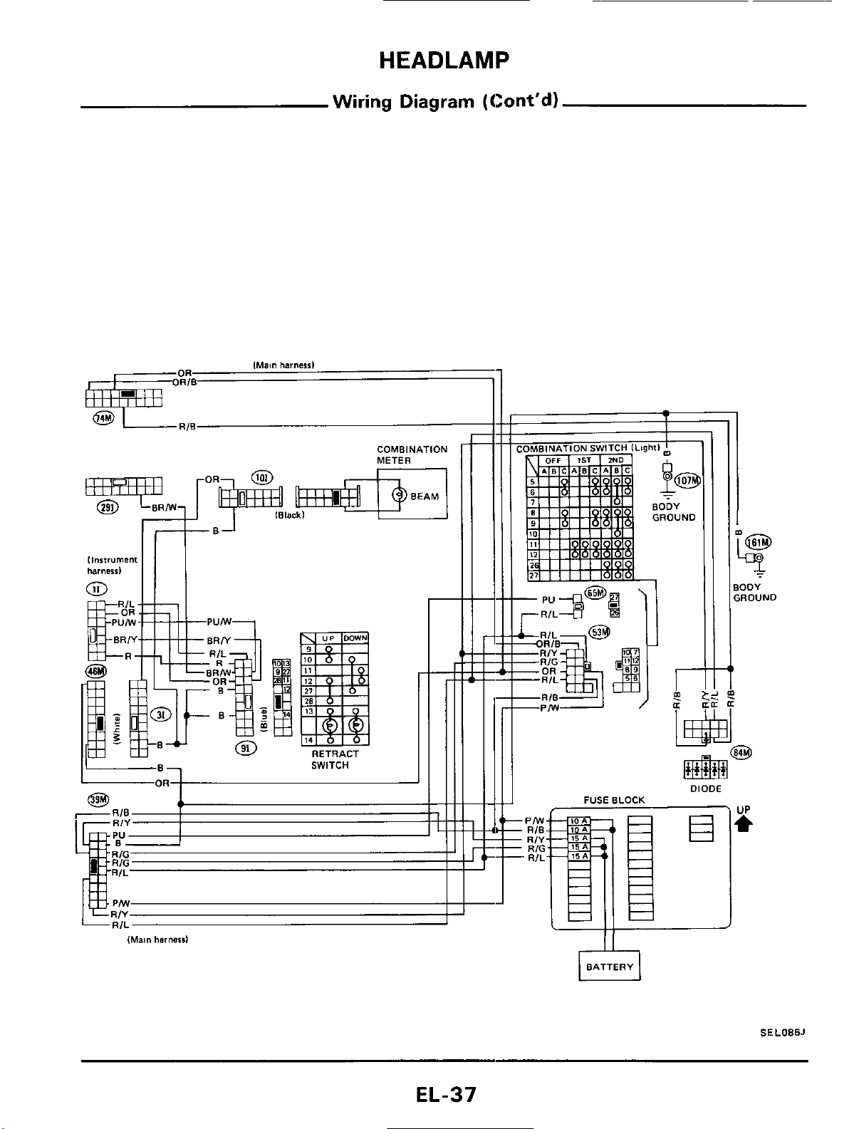
HEADLAMP
Wiring Diagram (Cont'd)
COMBINATION
METER
0
II
I
-..
,
-OR
-R/L
-RIB
I
I
m
r
IE
.
DIODE
FUSE
BLOCK
Pffl
RIB
-
RIY
-
RIG
-
RIL
T
ODY
,ROUND
3
rl
BATTERY
SEL085J
EL-37
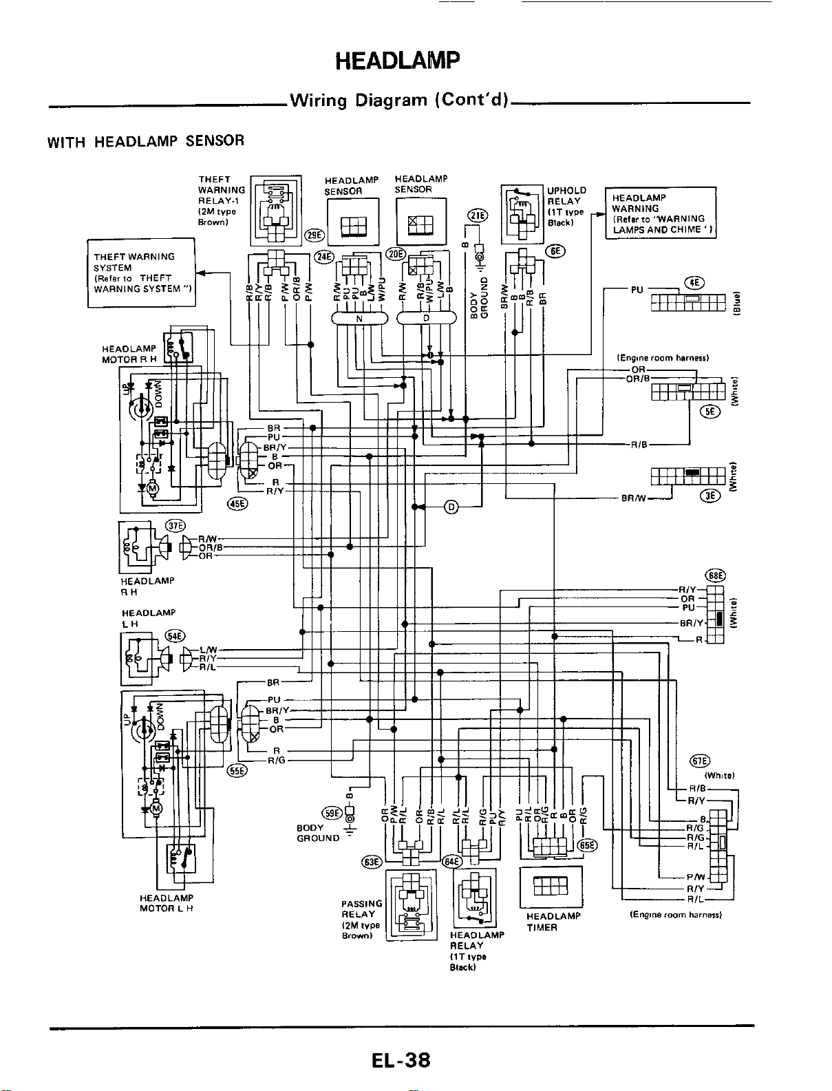
HEADLAMP
Wiring Diagram (Cont’d)
WITH HEADLAMP
SENSOR
EL-38
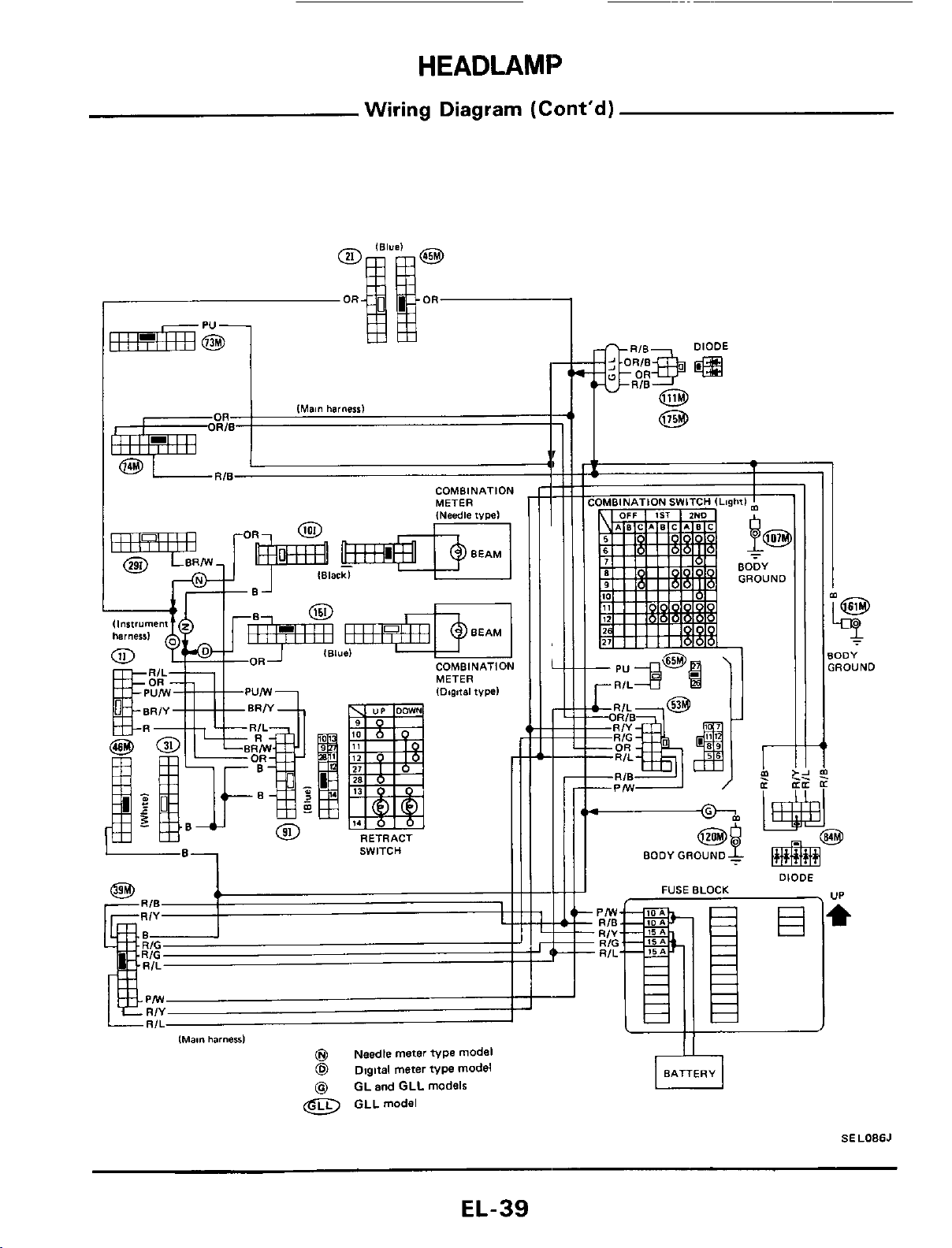
HEADLAMP
Wiring Diagram
(Cont'd)
COMBINATION
MFTVR
COMBINATION
SWITCH
J
t
lMam
harneal
@
Needle meter
type
model
@
Digital meter
type
model
@
GL and GLL models
@
GLLmodel
r
-OR
-RIL
-PIW
@g
--
BODY GROUND
-
BODY
GROUND
DIODE
.
UP
FUSE BLOCK
SELOBSJ
EL-39
HEADLAMP
OFF
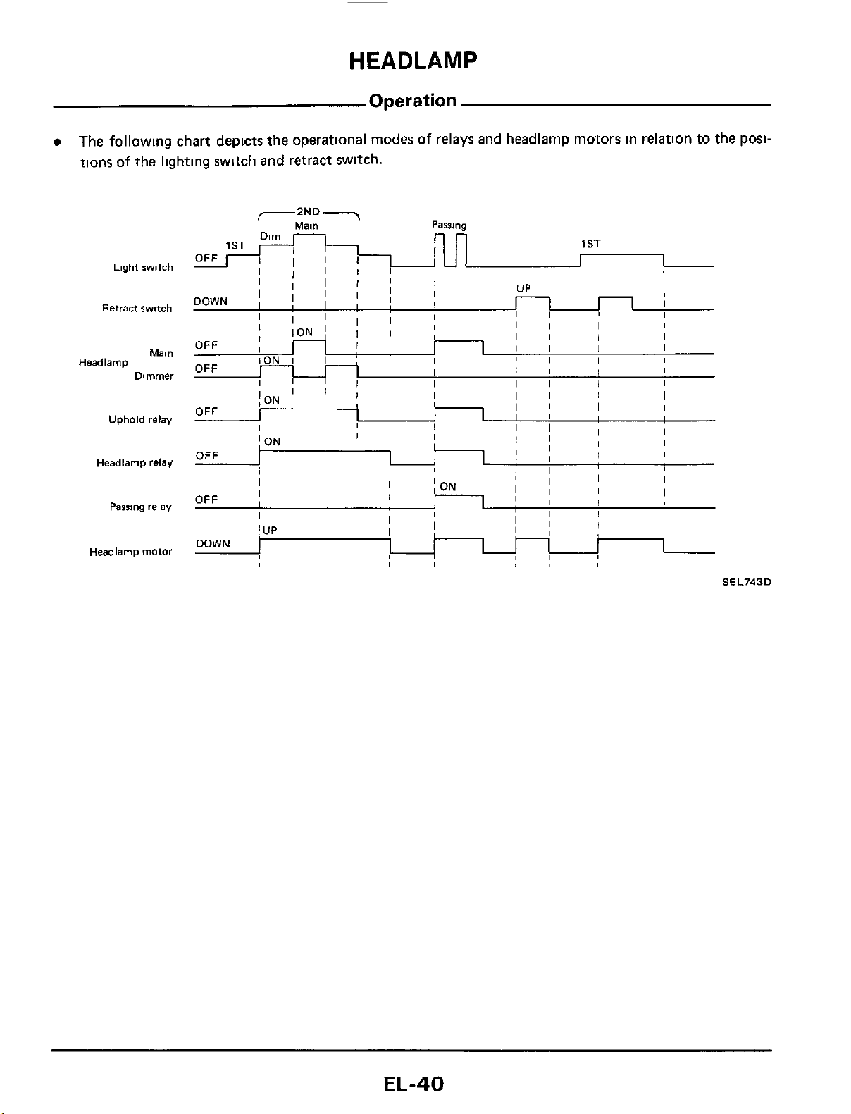
Operation
The followlng chart depicts the operational modes of relays and headlamp motors in relation to the posi-
tions of the lightlng switch and retract switch.
;I
I
I
Light
switch
Retract switch
Mal"
Dimmer
Headlamp
Uphold relay
Headlamp
relay
Passing
relay
Headlamp motor
SEL743D
EL-40
HEADLAMP
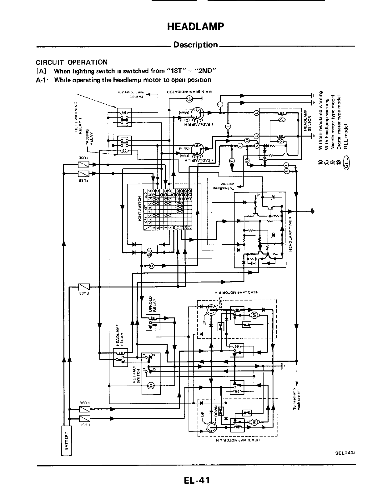
Description
CIRCUIT
OPERATION
[AI When lighting switch
IS
switched from "lST"+ "2ND"
A-1. While operating the headlamp motor to open position
SEL240J
EL-41
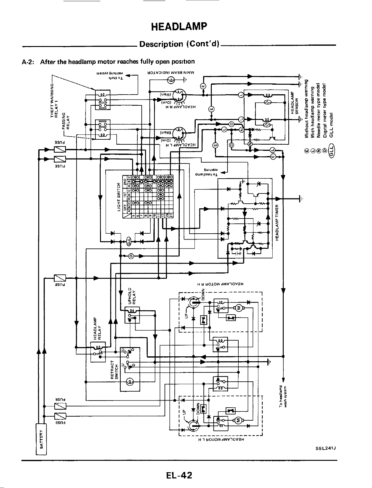
HEADLAMP
Description (Cont'd)
A-2: After the headlamp motor reaches
fully
open position
SEL241J
EL-42
HEADLAMP
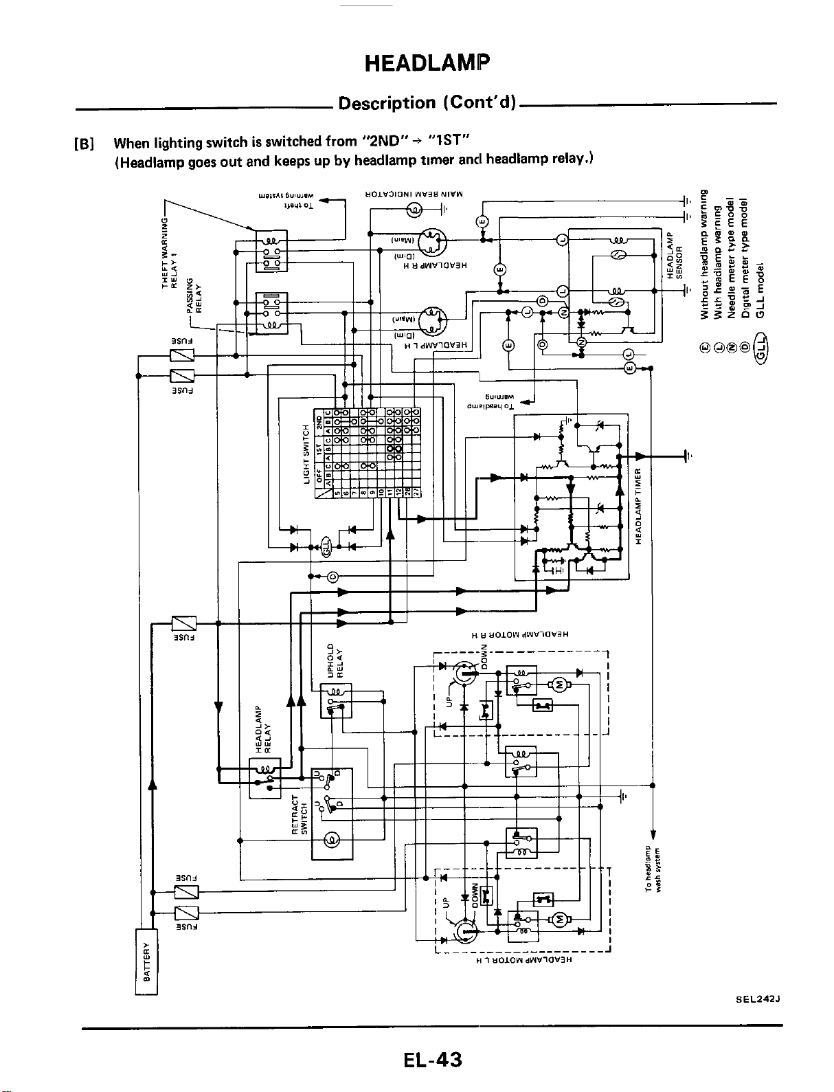
Description
(Cont'd)
[B]
When lighting switch
is
switched from
"2ND"
+
"IST"
(Headlamp goes out and keeps up
by
headlamp timer and headlamp relay.)
c
I'
SEL242J
EL-43
HEADLAMP
Description
(Cont'd)
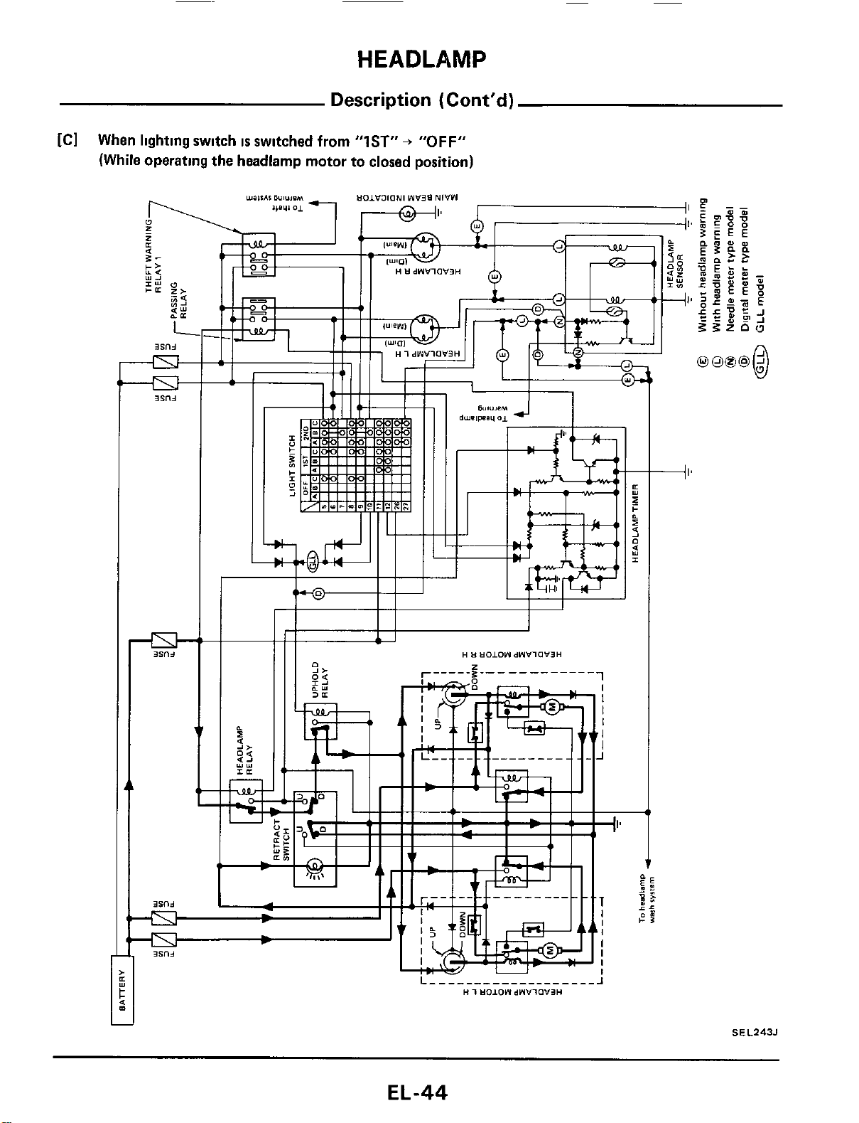
[Cl
When lighting switch
IS
switched from
"IST"
+
"OFF"
(While operating the headlamp motor
to
closed position)
c
J
SEL243J
EL-44
HEADLAMP
Description (Cont'd)
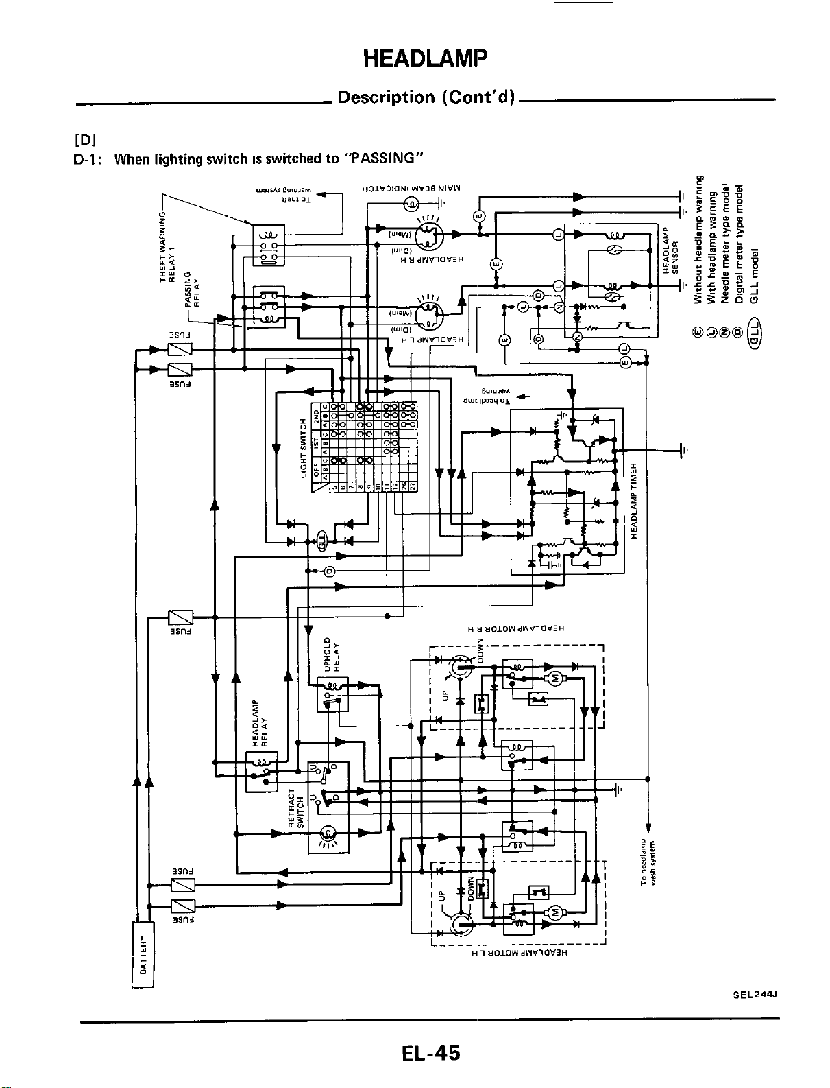
Dl
D-I
:
When lighting switch
IS
switched to "PASSING"
j
SEL2W
EL-45

HEADLAMP
Description (Cont'd)
D-2:
After releasing lighting switch from "PASSING"
(While operating the headlamp motor to open position)
1;
11
1
I
Ah
S
E
L245J
Closing operation
is
the same
as
IC] when llghtlng switch
IS
switched
from
"1ST"
+
"OFF"
EL-46
HEADLAMP
Description (Coiit'd)
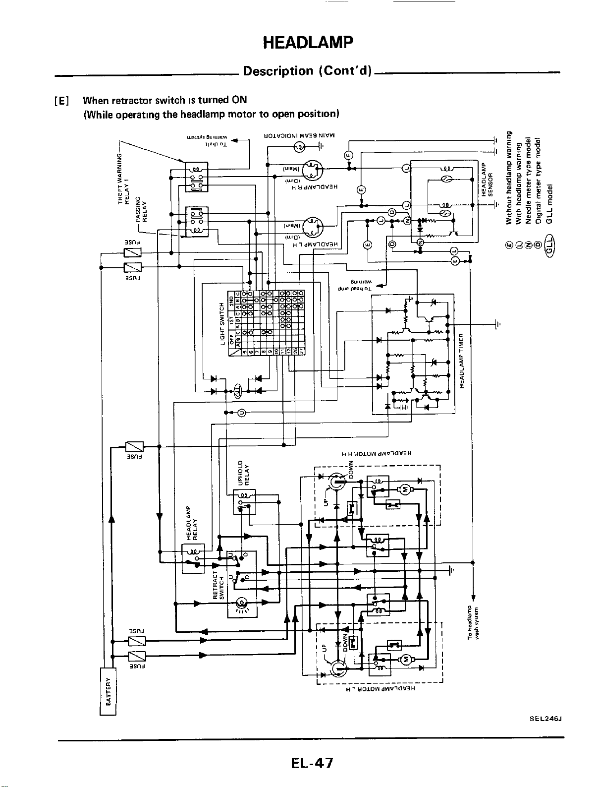
[El
When retractor switch
is
turned
ON
(While operating the headlamp motor to open position)
SEL246J
EL-47
HEADLAMP
Description
(Cont’d)
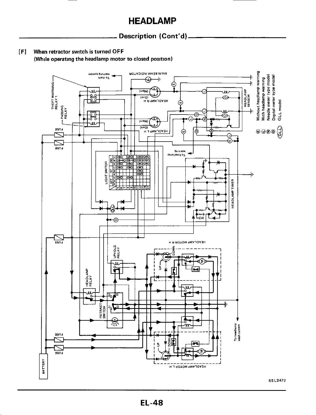
[Fl
When retractor switch
is
turned
OFF
(While operating the headlamp motor
to
closed position)
+I*
SEL247J
EL-48
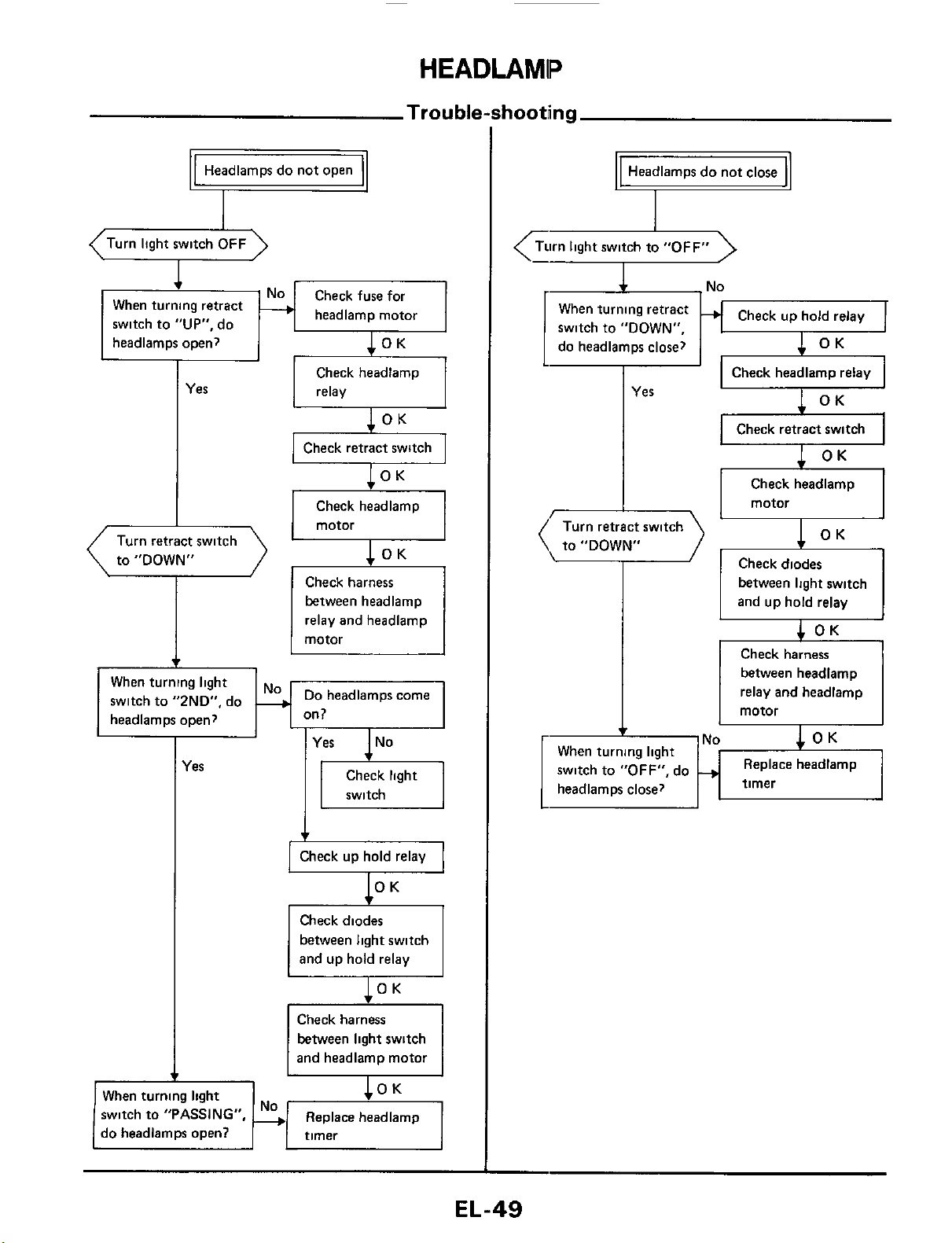
HEADLAMP
Trouble-shooting
-No
When turning light
headlamps close?
switch to
"OFF",
do
+
Headlamps do not open
v
between light switch
and up hold relay
4
OK
Check harness
between headlamp
relay and headlamp
motor
OK
Replace headlamp
timer
(Turn light switch
OFF
\
1
When turning retract
switch to
"UP",
do
headlamm ooen?
lOK
headlamp motor
I
I
&
..
Yes
Check headlamp
I
relay
Check headlamp
to "DOWN"
Check harness
between headlamp
relay and headlamp
Do
headlamps come
When turning light
switch to "2ND", do
headlamps open?
I
les
switch
Check diodes
between light switch
Check harness
between light switch
1
and headlamp motor
I
I
When turning light
switch to
"PASSING",
Replace headlamp
do headlamps open?
Headlamps do not close
+
Turn light switch to
"OFF"
<:-r2
Check up hold relay
When turning retract
switch
to
"DOWN",
do headlamps close?
Check headlamp relay
I
Yes
x
I I
Check retract switch
I
I I
Check headlamp
I
to "DOWN"
Check diodes
EL-49
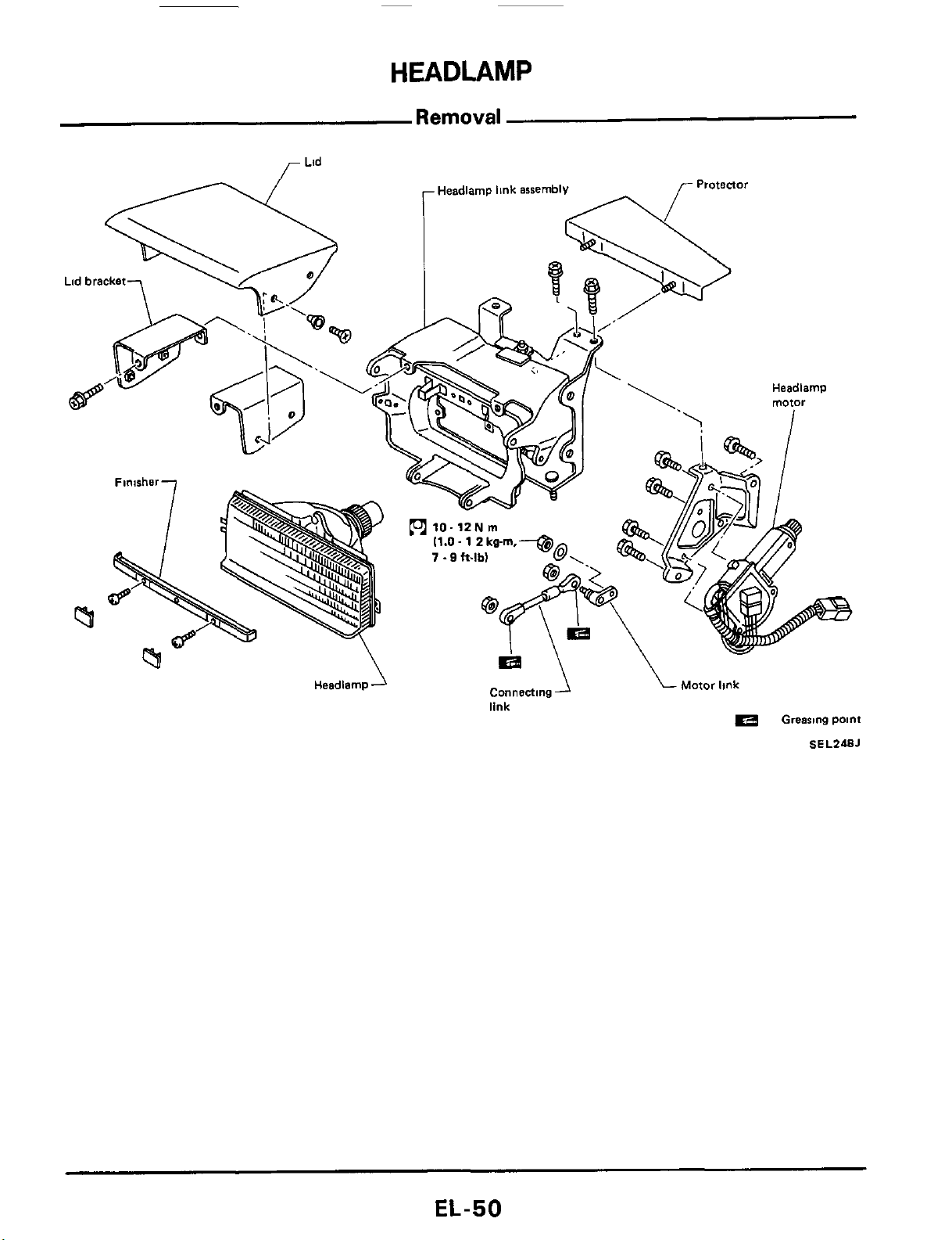
HEADLAMP
Removal
Lid
Motor
link
Connecting
link
Headlamp
Grearme
paint
SEL248J
EL-50
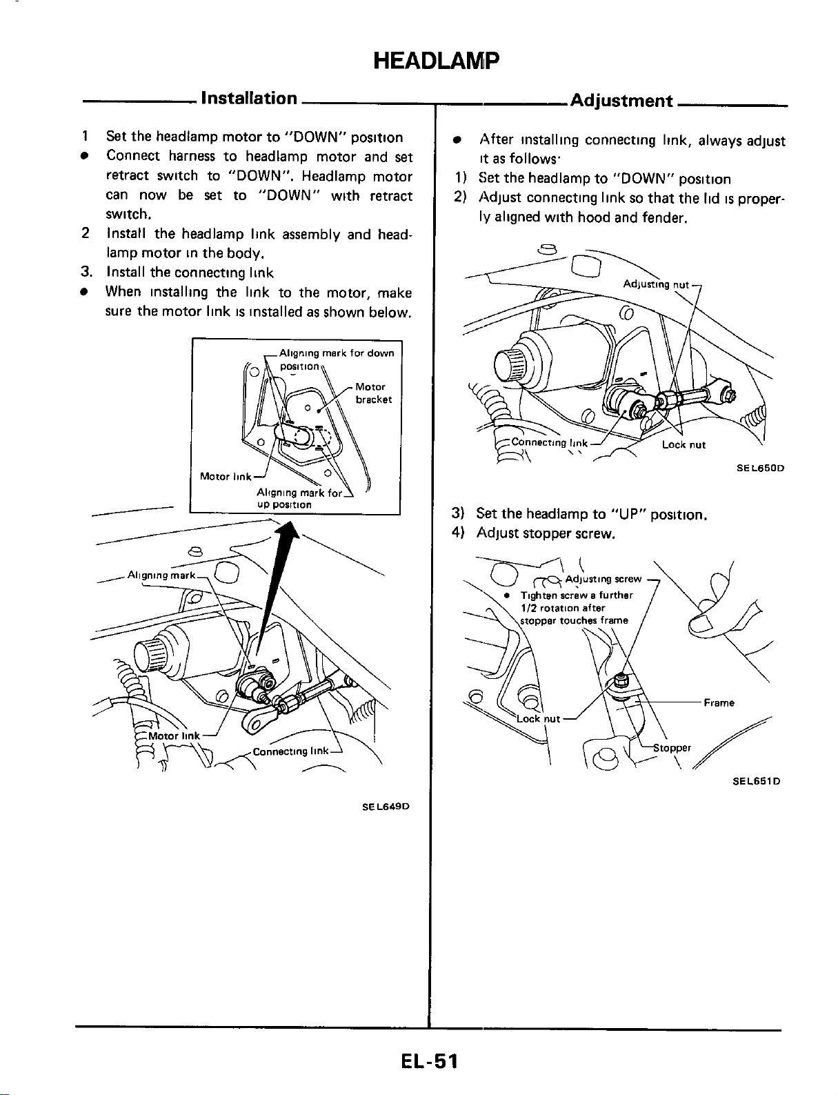
HEADLAMP
Installation
1
Set
the headlamp motor to "DOWN" position
Connect harness to headlamp motor and
set
retract switch to "DOWN". Headlamp motor
can now be
set
to "DOWN" with retract
switch.
Install the headlamp link assembly and head-
lamp motor in the body.
When installing the link to the motor, make
sure the motor link
is
installed
as
shown below.
2
3.
Install the connecting link
I
,Aligning
mark
for
down
SEL649D
-
Adjustment
After installing connecting link, always adjust
it
as
follows
1)
Set
the headlamp to "DOWN" position
2)
Adjust connecting link
so
that the lid
is
proper-
ly
aligned with hood and fender.
3)
Set
the headlamp to
"UP"
position.
4)
Adjust stopper screw.
SEL651D
EL-51
HEADLAMP
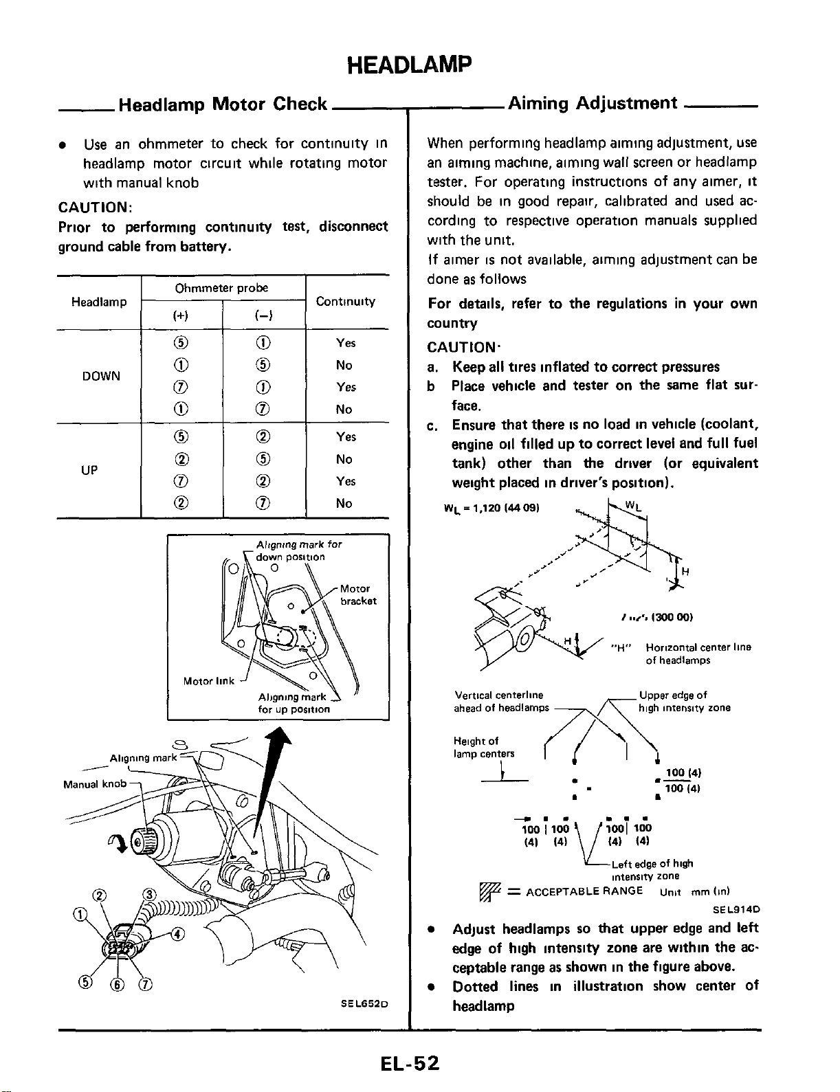
Headlamp
Headlamp Motor Check
Use
an ohmmeter to check for continuity in
headlamp motor circuit while rotating motor
with manual knob
CAUTION:
Prior to performing continuity
test,
disconnect
ground cable from battery.
Continuity
(+I
(4
0
0
Yes
I
Ohmmeter
orobe
I
0
0
0
0
0
UP
0
No
0
Yes
0
No
0
Yes
0
No
Motoi
--
for
up
position
SELS52D
Aiming Adjustment
When performing headlamp aiming adjustment, use
an aiming machine, aiming wall screen or headlamp
tester.
For operating instructions
of
any aimer,
it
should be in good repair, calibrated and used ac-
cording to respective operation manuals supplied
with the unit.
If
aimer
is
not available, aiming adjustment can
be
done
as
follows
For
details,
refer to the regulations
in
your own
country
CAUTION.
a.
Keep
all
tires inflated to correct pressures
b
Place vehicle
and
tester on the same flat
sur-
face.
c. Ensure
that
there
is
no load
in
vehicle (coolant,
engine oil filled up to correct level and full fuel
tank) other
than
the driver (or equivalent
weight placed
in
driver's position).
WL
=
H
j
1,120
14409)
"H"
Horizontal
center
line
of
headlamps
edge
Of
Vertical
centerline
ahead
of
headlamps
high
intensity
zone
Height
of
lamp
centers
100
141
100
(41
.-
-.-
...
(41
(4)
14) 14)
LLeft
edge
of
huh
intensity
zone
=
ACCEPTABLE
RANGE
unit
mm
(in)
SE
L9140
Adjust headlamps
so
that
upper edge and left
edge
of
high
intensity zone are within the ac-
ceptable range
as
shown in the figure above.
Dotted lines
in
illustration show center of
headlamp
EL-52
H
EADLAM
IP
-
Aiming Adjustment (Cont'd)
-
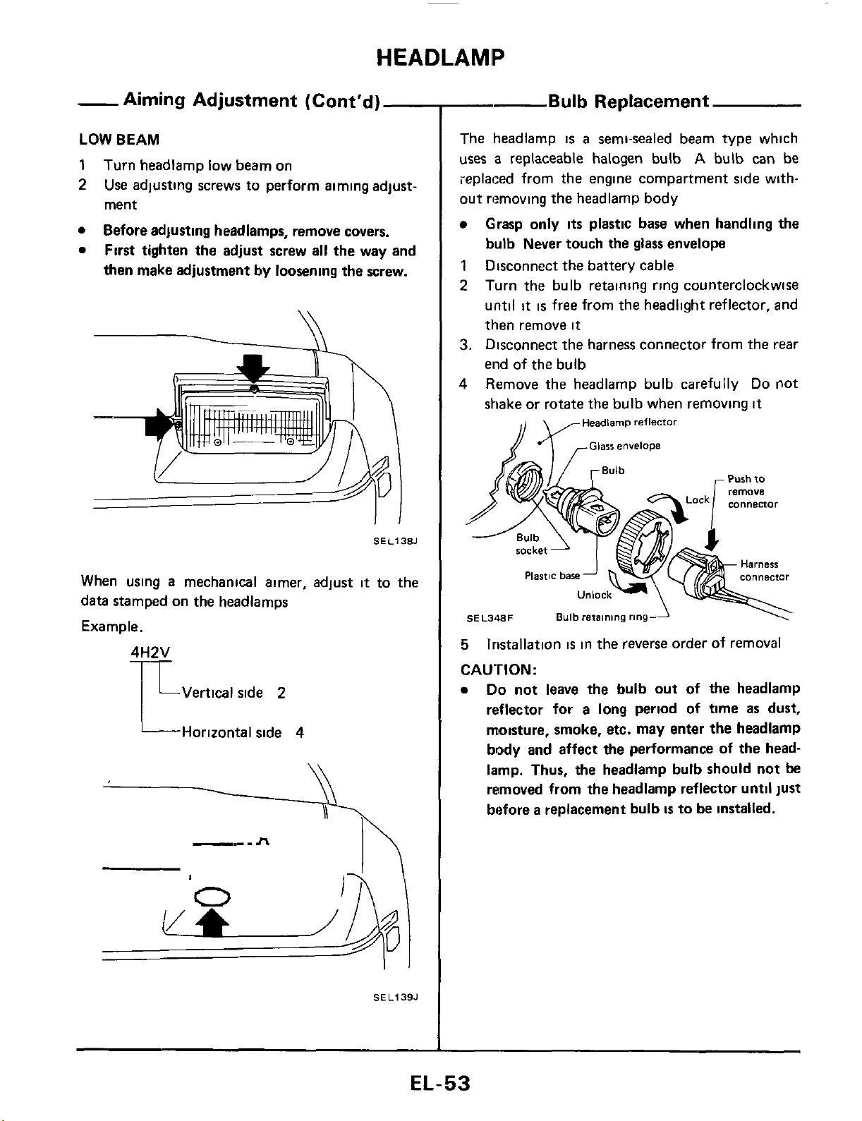
LOW
BEAM
1
2
Turn headlamp low beam on
Use
adjusting screws to perform aiming adjust-
ment
Before adjusting headlamps, remove covers.
First tighten the adjust screw all the way and
then make adjustment
by
loosening the screw.
SEL138J
When using
a
mechanical aimer, adjust
it
to the
data stamped on the headlamps
Example.
LVertical side
2
L
Horizontal side
4
\\
SEL139.1
-
Bulb
Replacement
The headlamp
is
a
semi-sealed beam type which
uses
a
replaceable halogen bulb
A
bulb
can
be
ieplaced from the engine compartment side with-
out rlmoving the headlamp body
Grasp only
its
plastic base when handling the
bulb Never touch
the
glass
envelope
1
Disconnect the battery cable
2
Turn the bulb retaining ring counterclockwise
until
it
is
free from the headlight reflector, and
then remove
it
3.
Disconnect the harness connector from the rear
end of the bulb
4
Remove the headlamp bulb carefully
Do
not
shake or rotate
the
bulb when removing
it
Headlamp
reflector
Purh to
Unlock-
\
SE
L348F
Bulb
retaining
ringA
\'
5
CAUTION:
lristallation
is
in the reverse order of removal
Do
not leave the bulb out of the headlamp
reflector
for
a long period of time
as
dust,
moisture, smoke, etc. may enter the headlamp
body
and
affect the performance of the head-
lamp. Thus, the headlamp bulb should not
be
removed from the headlamp reflector until just
before
a
replacement bulb
is
to be installed.
EL-53
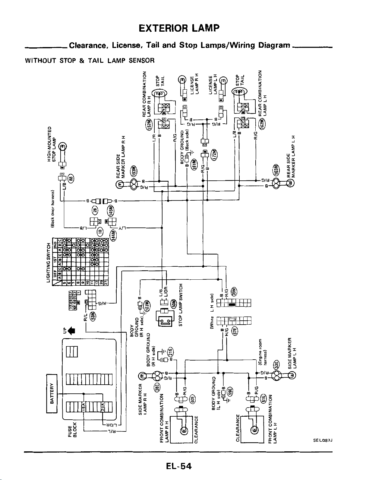
EXTERIOR
LAMP
Clearance, License, Tail and Stop Lamps/Wiring Diagram
WITHOUT
STOP
&
TAIL LAMP
SENSOR
E
m
111111111111
L
I
4l
SEL087J
EL-54
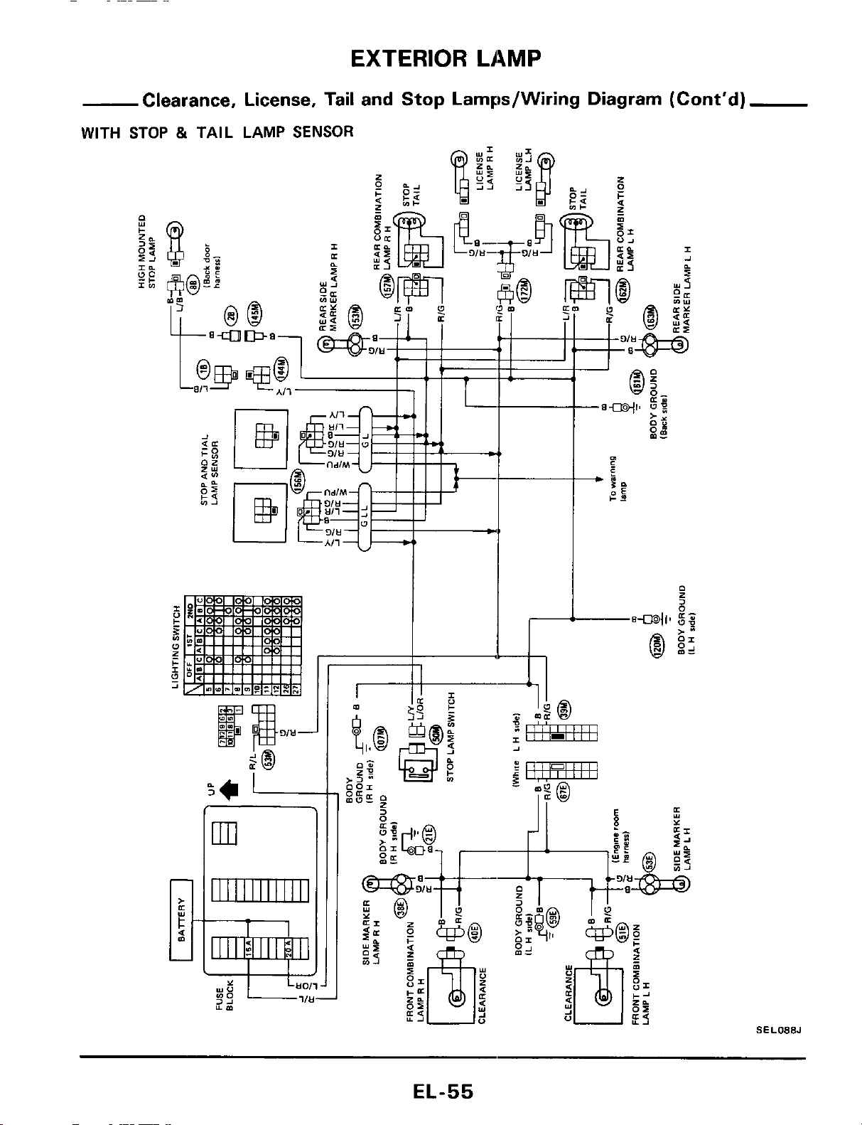
EXTERIOR
LAMP
Clearance, License, Tail and Stop Larnps/Wiring Diagram (Cont’d)
WITH STOP
&
TAIL LAMP
SENSOR
SEL088J
EL-55
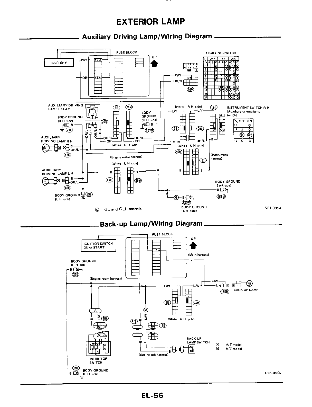
EXTERIOR
LAMP
Auxiliary Driving Lamp/Wiring Diagram
LIGHTING SWITCH
INSTRUMENTSWITCH
R
H
lAuxiliary
driving
Imp
AVXILIARYDRIVING
LAMP RELAY
AUXILIARY
DRIVING LAMP
R
H
l~ng,ne
morn
harness1
[White L
H
ridel
AUXILIARY
DRIVING LAMP
L
H
BODYGROUND
[Back
ride1
BODYGROUND
SEL089J
IL
H
ride)
(@
GL
and
GLL
models
Back-up Lamp/Wiring Diagram
BODYGROUND
IR
H
ride)
@
BACKUPLAMP
(White
R
H
sodel
BACK UP
LAMPSWITCH
0
AITmodsl
@
MTTrnodsl
[Engine
ruMarneid
INHIBITOR
SWITCH
@
BODY GROUND
qLL
H
sidel
SELOIIOJ
-
EL-56
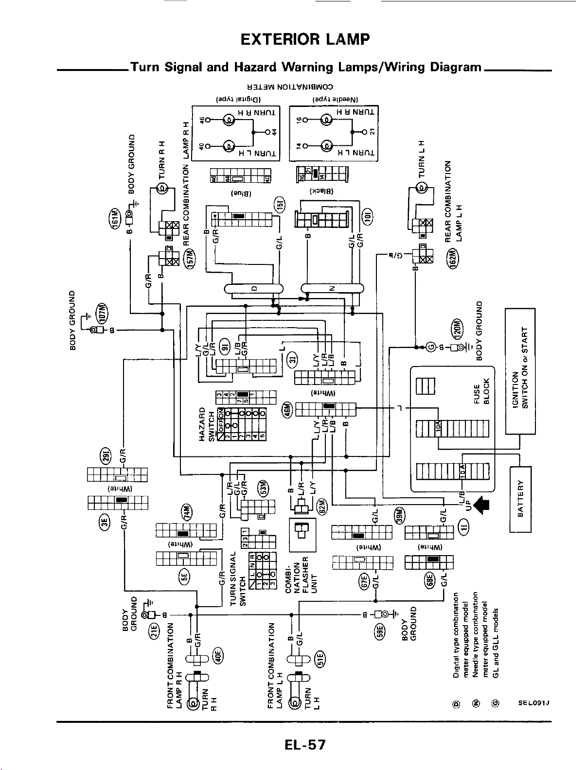
EXTERIOR
LAMP
Turn Signal and Hazard Warning Lamps/Wiring Diagram
H313W
NOIIVNIPWO3
r-
t1
m
SELO91J
EL-57
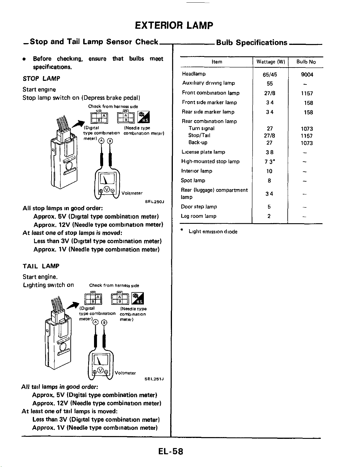
EXTERIOR
LAMP
-Stop and Tail Lamp Sensor Check-
Before checking, ensure
that
bulbs meet
STOP LAMP
Start engine
Stop lamp switch on (Depress brake pedal)
specifications.
Check
from
harness
skde
(Needle
type
v
SEL250J
All stop lamps in good order:
Approx.
5V
(Digital type combination meter)
Approx.
12V
(Needle type combination meter)
Less
than
3V
(Digital type combination meter)
Approx.
1V
(Needle type combination meter)
At
least
one
of
stop lamps
is
moved:
TAIL LAMP
Start engine.
Lighting WltCh On
Check
from
harness side
INeedle type
SEL251J
All tail lamps
in
good
order:
Approx.
5V
(Digital type combination meter)
Approx.
12V
(Needle type combination meter)
Less than
3V
(Digital
type
combination meter)
Approx.
1V
(Needle type combination meter)
At
least
one
of
tail
lamps
is
moved:
Bulb
Specifications
Item
Headlamp
Auxiliary driving lamp
Front combination lamp
Front side marker lamp
Rear side marker lamp
Rear combination lamp
Turn signal
StopITail
8ack-up
License plate lamp
Highmounted stop lamp
Interior lamp
Spot lamp
Rear (luggage) compartment
lamp
Door
step lamp
Leg room lamp
Light emission diode
Wattage
(W)
65/45
55
2718
34
34
27
2718
27
38
7
3"
10
8
34
5
2
~~
Bulb No
9004
-
1157
158
158
1073
1157
1073
-
-
-
-
-
-
-
EL-58
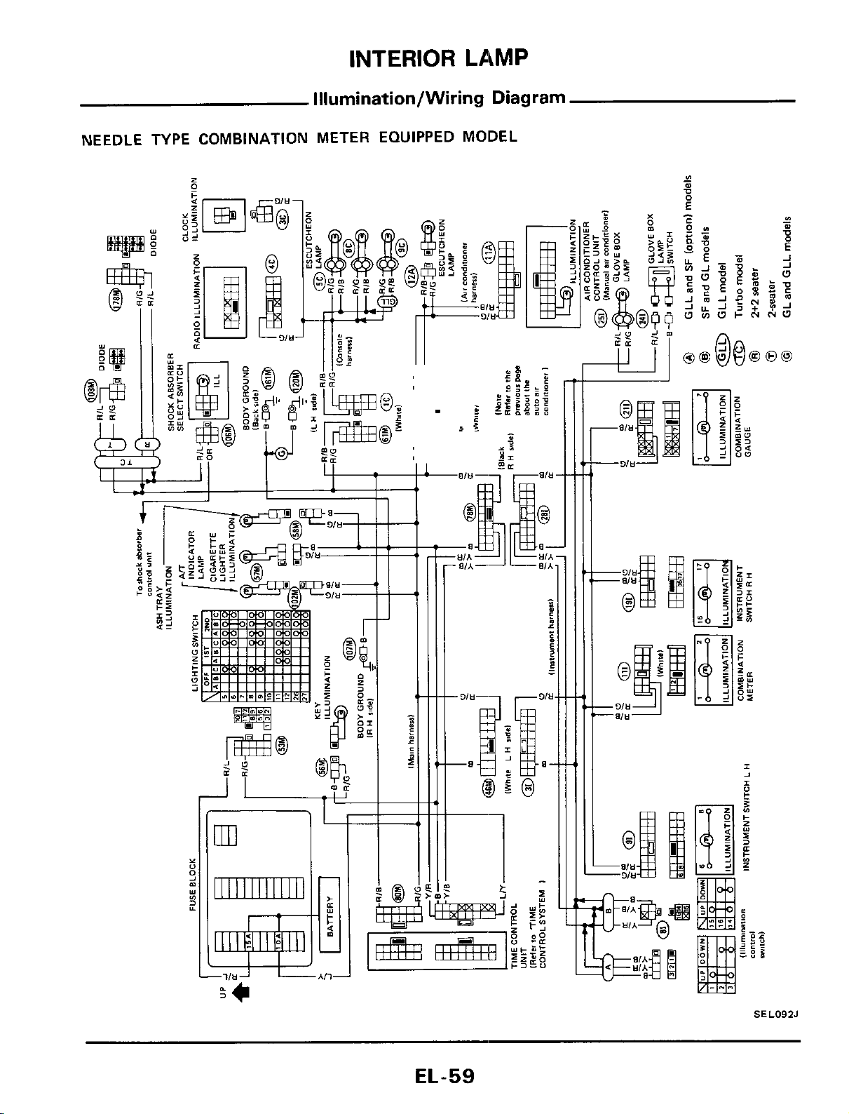
INTERIOR
LAMP
Illumination/Wiring Diagram
NEEDLE TYPE COMBINATION METER EQUIPPED MODEL
SEL092J
EL-59
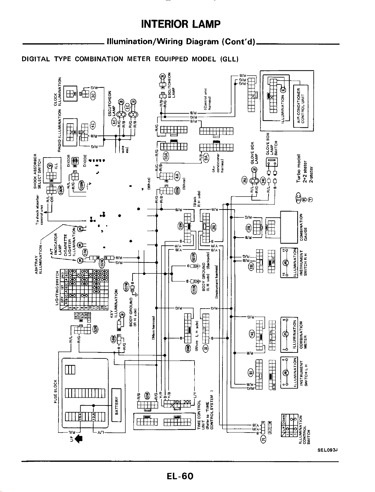
INTERIOR
LAMP
Illurnination/Wiring Diagram (Cont'd)
DIGITAL TYPE COMBINATION METER EQUIPPED MODEL (GLL)
Y
"
s
s
m
YI
1111111111111
LJ
'F*
3
EL-60
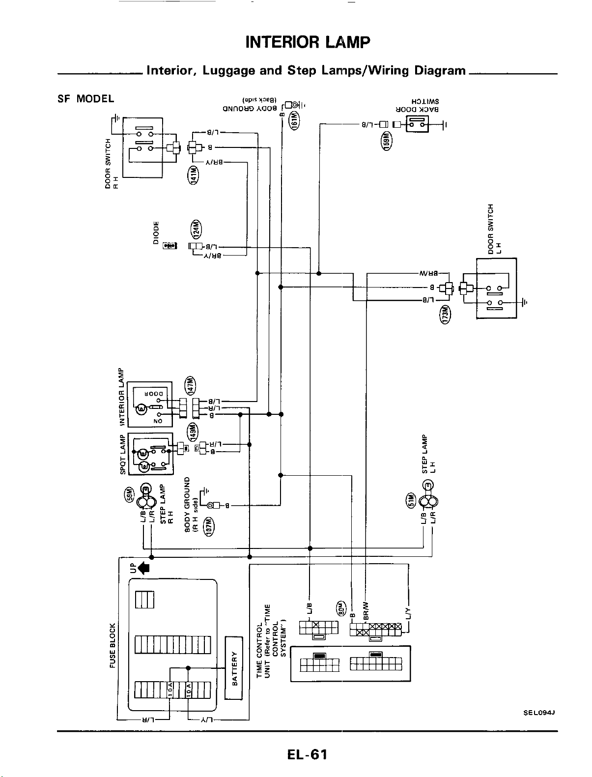
INTERIOR LAMP
Interior, Luggage and Step Lannps/Wiring Diagram
SF
MODEL
-
Y
0
m
3
9
Y
v)
Y
ml
II
I I I I
I I I I
I
I1
rt-
I1
*<
00
--
I
II
1
.
>
J
SEL094J
EL-61
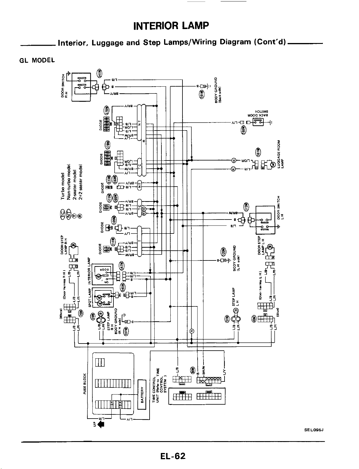
INTERIOR
LAMP
Interior, Luggage and Step Lamps/Wiring Diagram (Cont'd)
GL
MODEL
SEL095J
EL-62
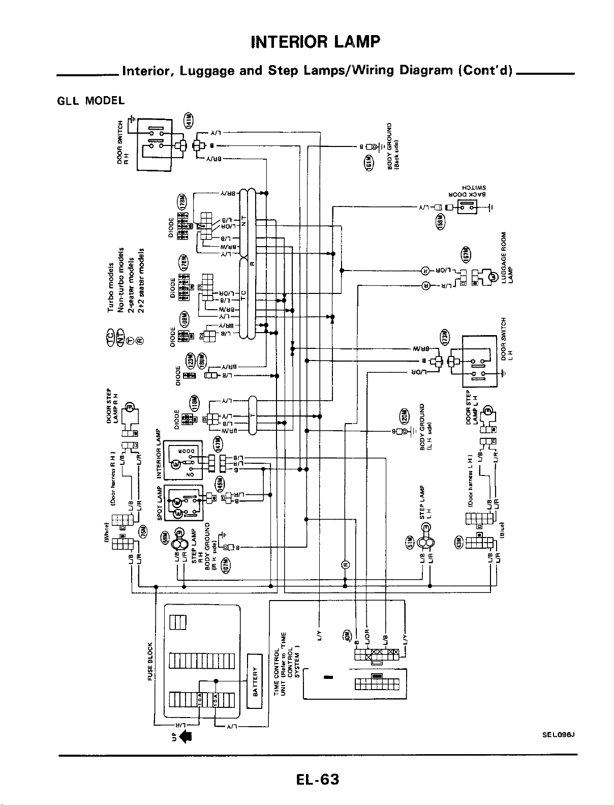
INTERIOR
LAMP
Interior, Luggage and Step Lamps/’Wiring Diagram (Cont’d)
GLL
ml
1111111111111
SELOSSJ
EL-63
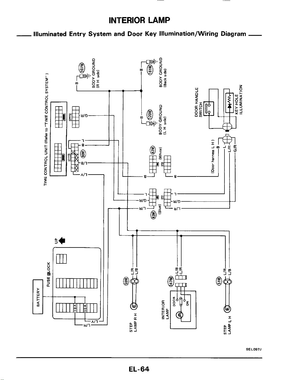
INTERIOR
LAMP
-
Illuminated Entry System and Door
Key
Illumination/Wiring Diagram
-
I
Y
0
9
Y
fn
3
Y
m
.
1
I
SEL097J
EL-64
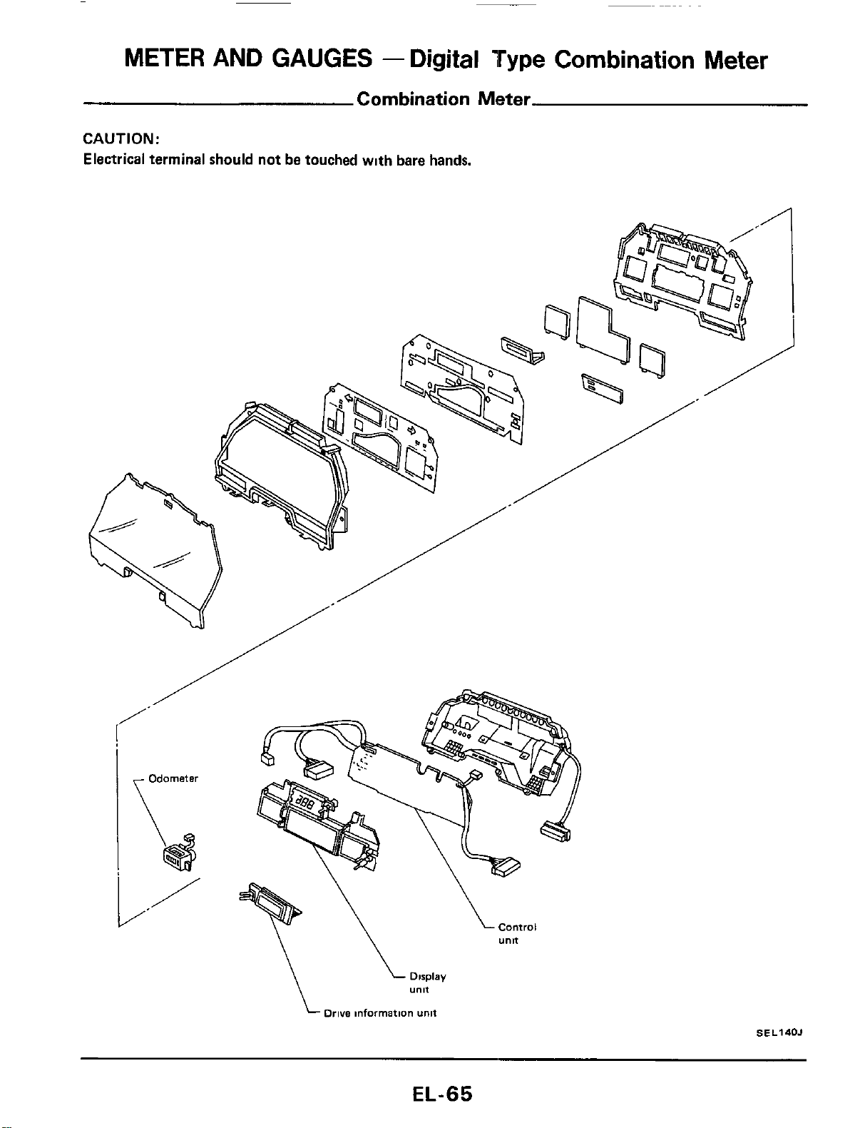
METER
AND GAUGES
-
Digital
Type
Combination
Meter
Combination Meter
CAUTION:
Electrical terminal should not be touched wlth bare hands,
Drive
information
unit
SE
L140J
EL-65
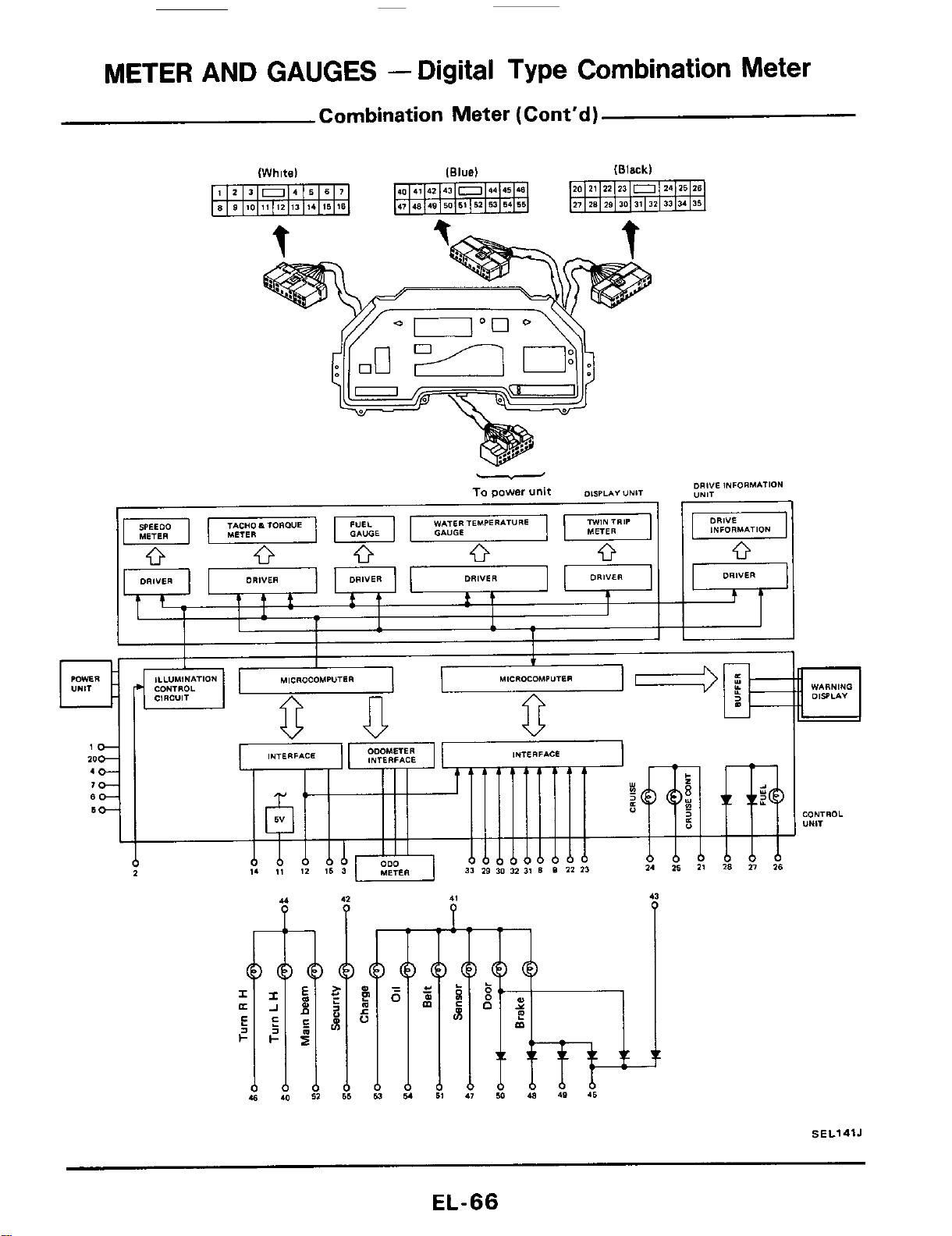
METER
AND GAUGES
-
Digital Type Combination Meter
Combination Meter (Cont'd)
(Whitel
(Black)
WARNING
DlSsLA"
CONTROL
"NlT
SEL141J
EL-66
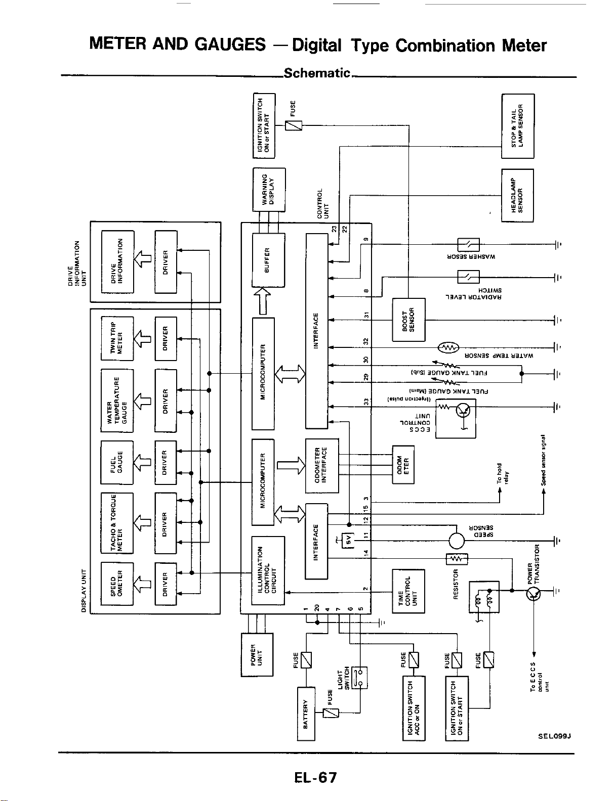
METER
AND
GAUGES
-
Digital Type Combination Meter
Schematic.
'17'
n
I'
I'
SEL099J
EL-67
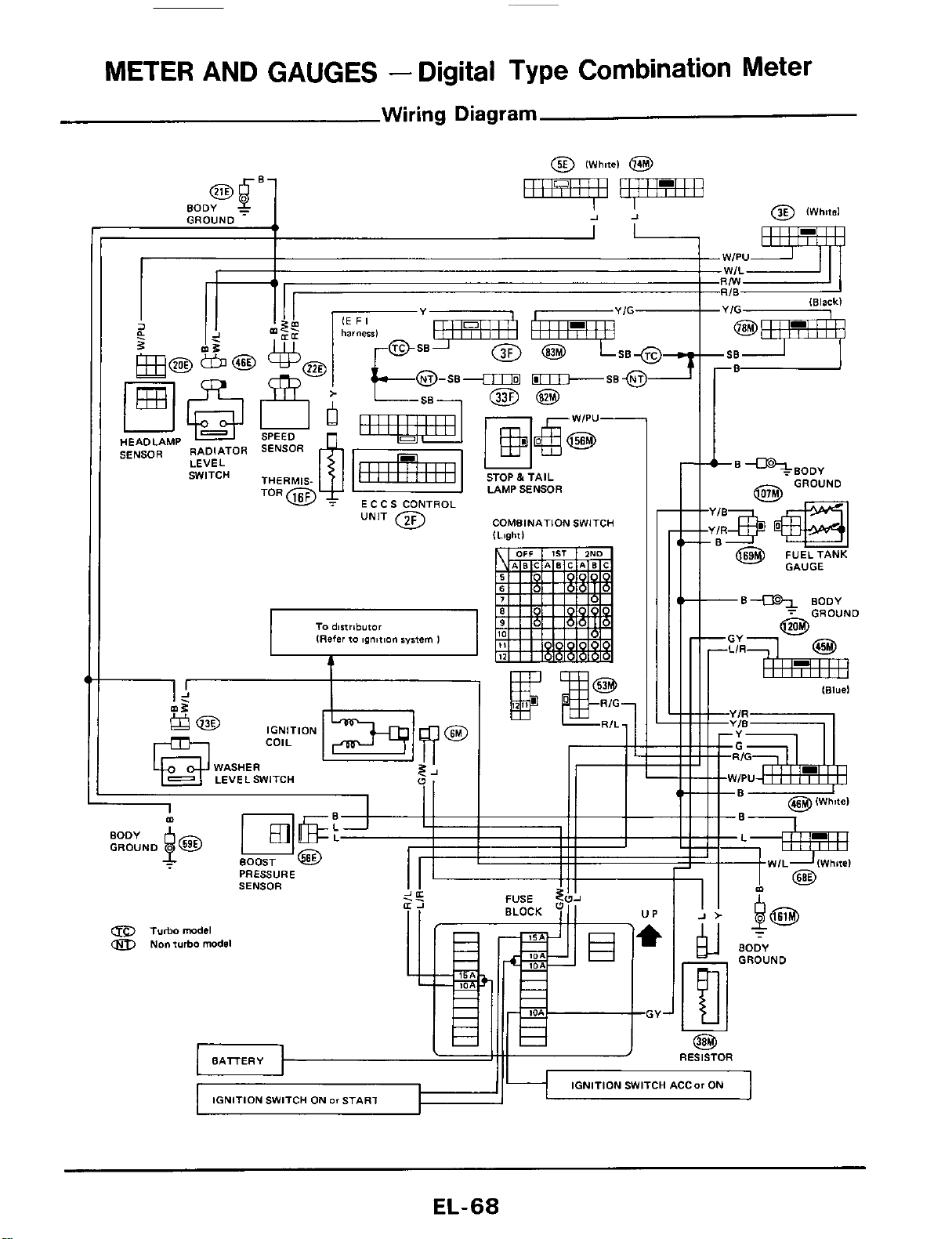
METER AND GAUGES
-
Digital Type Combination Meter
Wiring
Diagram
a
I
I!
2
-.z.
HEADLAMP
SENSOR
RADIATOR
LEVEL
SWITCH
'-"w
ECCS CONTROL
COMBINATION SWITCH
I1
I I
I4
$
COIL IGNITION
WASHER
LEVELSWITCH
91
II
I
PRESSURE
SENSOR
a
Turbomodel
Non turbo model
EL-68

METER AND GAUGES
-
Digital Type Combination Meter
Wiring Diagram (Cont'd)
L
MWIPU
To
AS
C
D
mntrcl
amp
(Refer
io
AS
C
D
I
TO
lock-up
mnfrol
unit
[Referto
AT
sealon
I
To
E
c c
S
mntrol
unit
IRafer
to
EF
maion
I
t
8f.l
SELlOOJ
EL-69
METER AND GAUGES
-
Digital
Type
Combination Meter
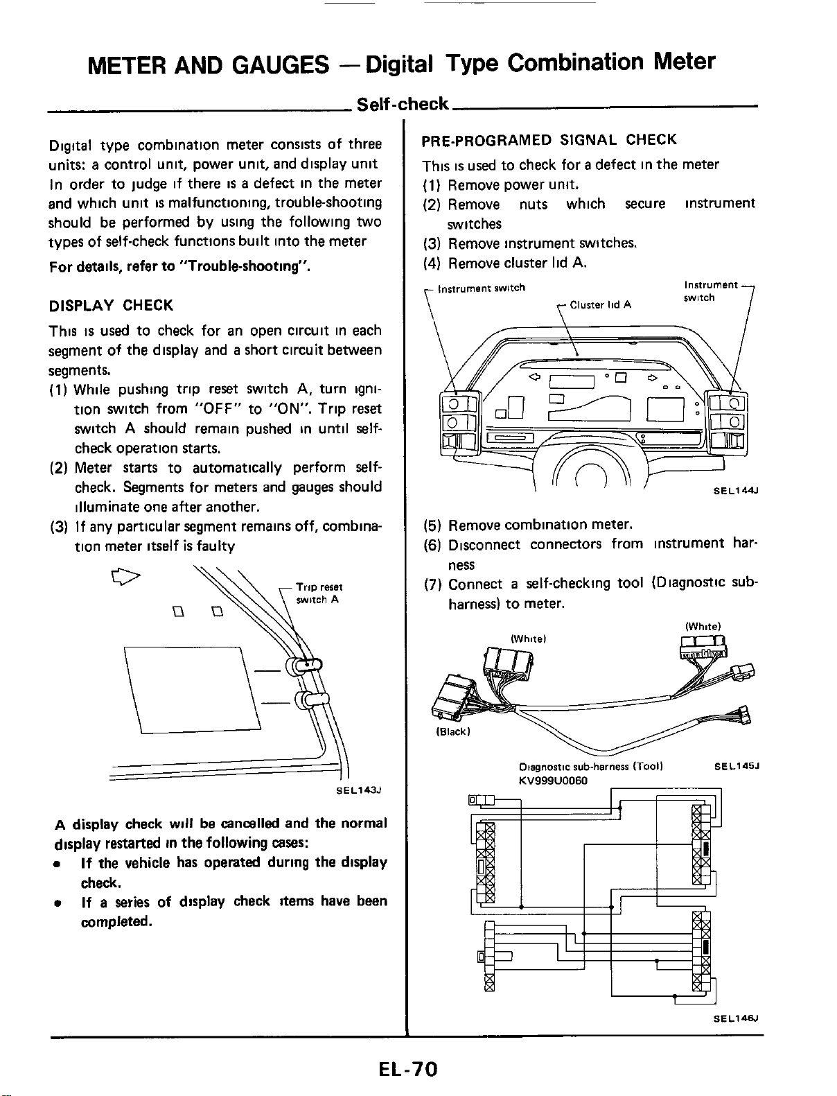
Self-check
Digital type combination meter consists of three
units:
a
control unit, power unit, and display unit
In order to judge if there
is
a
defect in the meter
and which unit
is
malfunctioning, troubleshooting
should be performed by using the following two
types of self-check functions built into the meter
For details, refer to "Trouble-shooting".
DISPLAY CHECK
This
is
used
to check for an open circuit in each
segment of the display and
a
short circuit between
segments.
(1)
While pushing trip reset switch
A,
turn igni-
tion switch from
"OFF"
to
"ON".
Trip reset
switch
A
should remain pushed in until self-
check operation starts.
(2)
Meter
starts
to automatically perform self-
check. Segments for meters and gauges should
illuminate one after another.
(3)
If any particular segment remains off, combina-
tion meter itself
is
faulty
SE L143J
A
display check
will
be cancalled and
the
normal
display restarted in the following
cases:
0
If
the vehicle has operated during the display
check.
0
If
a
series of display check items have been
completed.
PRE-PROGRAMED SIGNAL CHECK
This
is
used
to check for
a
defect in the meter
(1)
Remove power unit.
(2)
Remove nuts which secure instrument
(3)
Remove instrument switches.
(4)
Remove cluster lid
A.
switches
instrument
swltch
instrument
witch
Cluster
lid
A
\
\
/-\
I
SEL144.l
(5)
Remove combination meter.
(6)
Disconnect connectors from instrument har-
(7)
Connect
a
self-checking tool (Diagnostic sub-
ness
harness) to meter.
Otagnastic
sub-harness
ITooil
SEL145J
KV999U0060
EL-70
METER
AND GAUGES
-
Digital
Type
Combination
Meter
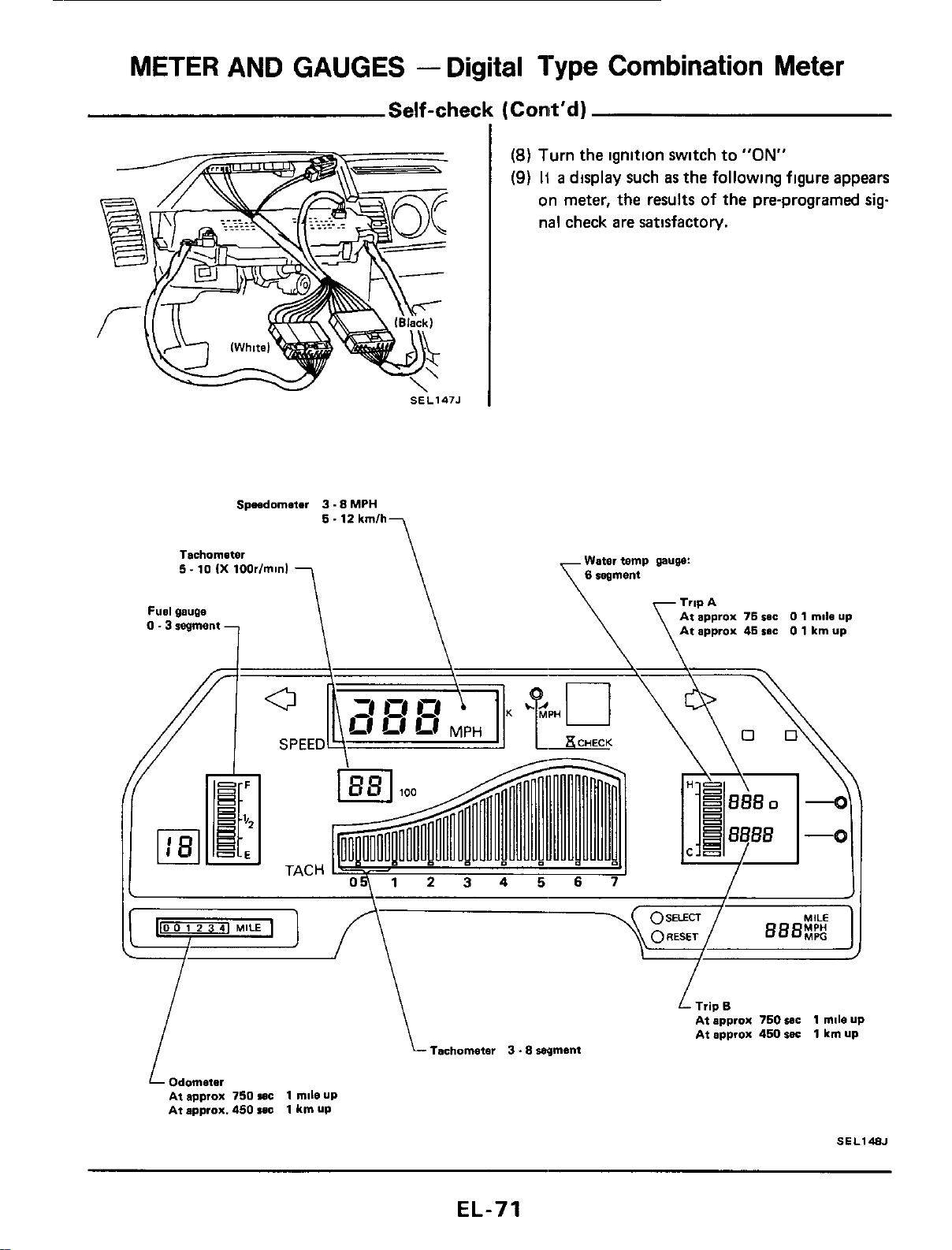
Self-check
(Conit'd)
I
(8)
Turn the ignition switch to
"ON"
(9)
H
a
display such
as
the following figure appears
on meter, the results of the pre-programed
sig
nal check are satisfactory.
Spndometer
3.8
MPH
5.12
kmlh
Tachommter Water temp
puw:
5.10
(X
100rIminl
Fuel
gau~e
I
\
Tachometer
3
.8
wment
Odometer
At approx
750
wc
1
mll0
UP
At approx.
450
I.E
1
km
UP
1
L
Trip
B
At approx
750
IC
1
mile up
At approx
460
suc
1
km
UP
SEL148J
EL-71
METER AND GAUGES
-
Digital
Type
Combination
Meter
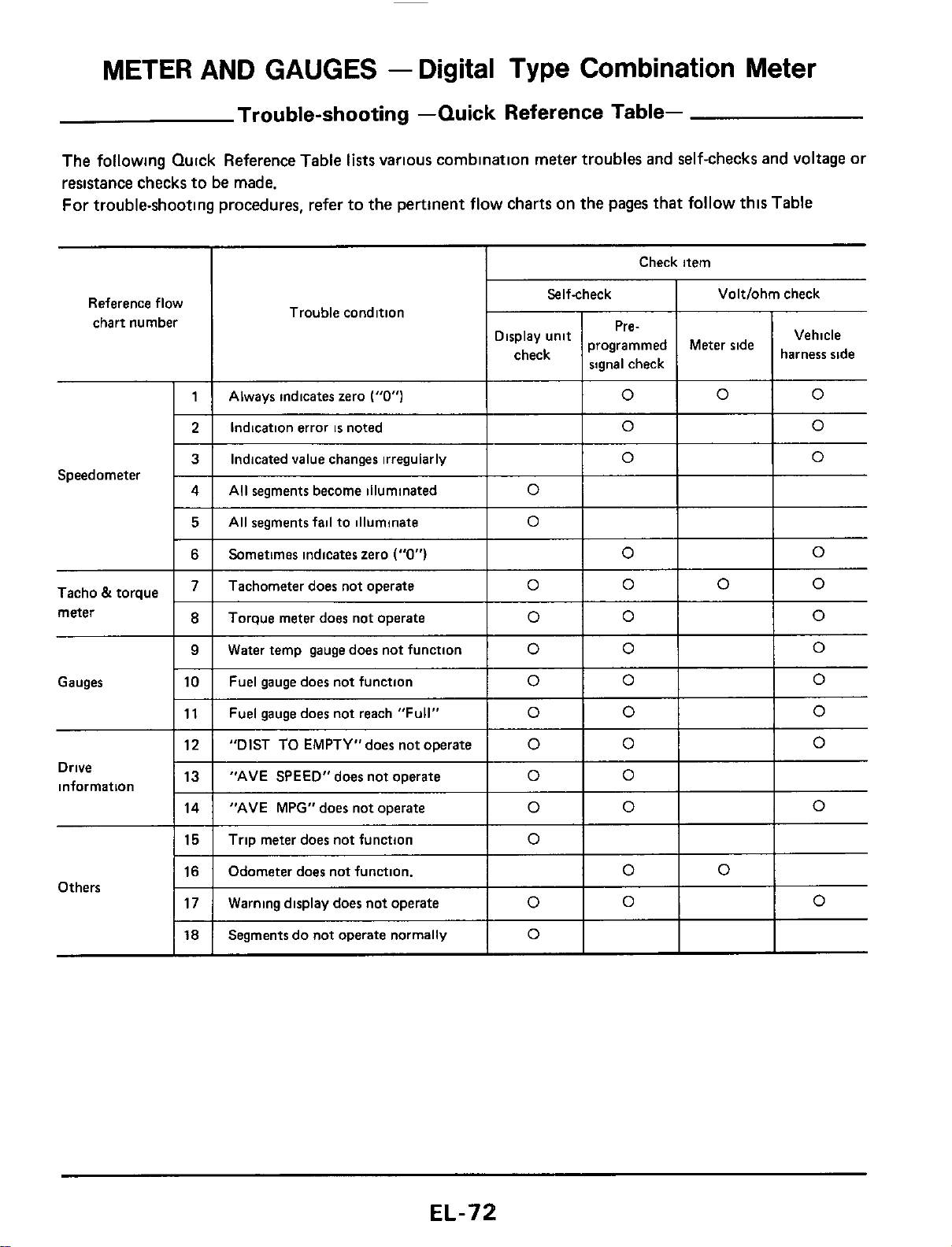
Trouble-shooting -Quick Reference Table-
The following Quick Reference Table
lists
varlous combination meter troubles and self-checks and voltage or
resistance checks to be made.
For trouble-shooting procedures, refer to the pertinent flow charts on the pages that
follow
thls Table
Always indicates zero
("0")
Reference flow
chart number
0
0 0
Check item
Indication error
is
noted
I
Selfcheck
I
Voltlohm check
0 0
3 Indicated value changes irregularly
0
0
Tacho
&
torque
meter
4
Gauges
All segments become illuminated
0
I
5
I
AII
segments fail to illuminate
lo1
I
I
Torque meter does not operate
Water temp gauge does not function
Fuel gauge does not function
Sometimes indicates zero
("0")
I
lo1
Io
0
0
0
0
0
0
0
0
0
Tachometer does not operate
lolololo
12
13
14
Drive
information
"DIST
TO
EMPTY"does not operate
0
0 0
"AVE SPEED"does not operate
0 0
"AVE MPG" does not operate
0 0 0
I
11
I
Fuel gaugedoes not reach "Full"
I
0
I
0
I
Io
15
16
17
Trip meter does not function
Odometer does not function.
0
0
0
Warning display does not operate
0
0
0
Others
18
Segments do not operate normally
0
METER AND GAUGES
-
Digital Type Combination Meter
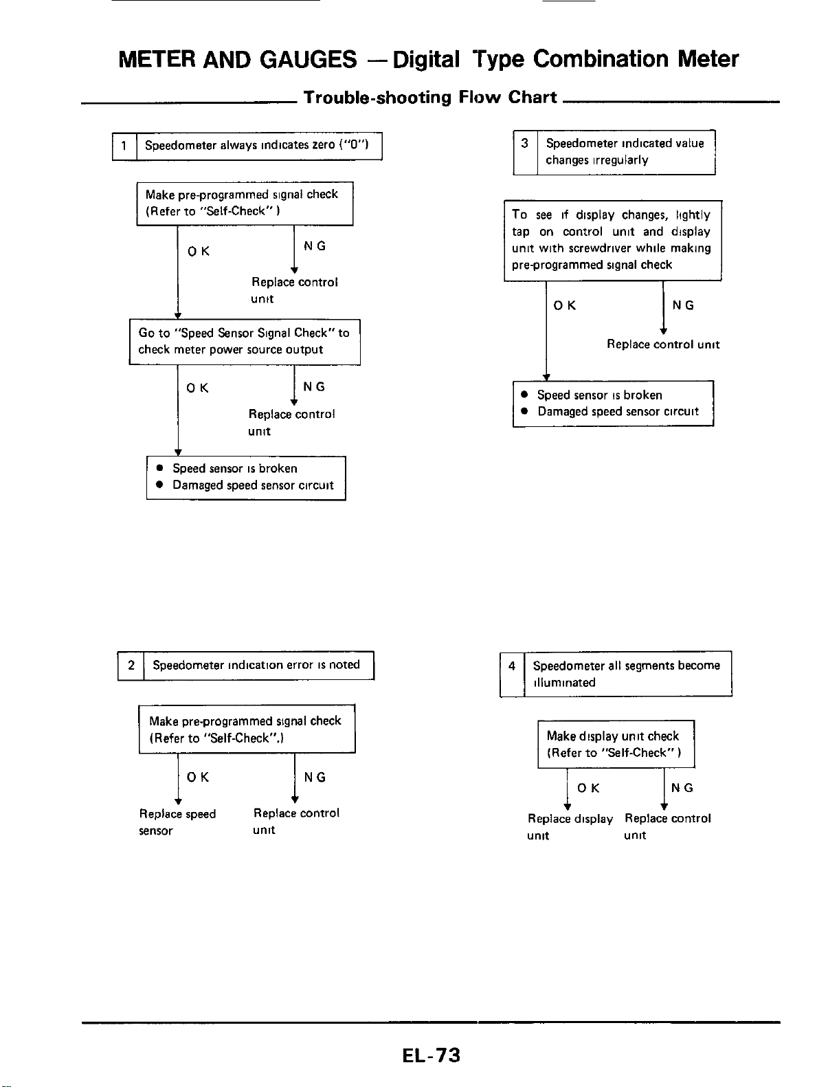
Trouble-shooting
Flow
Chart
I
1
I
Speedometer always indicates zero
("0")
I
Make pre-programmed signal check
(Refer to "Self-Check"
)
I
t
Replace control
I
unit
Go
to
"Speed Sensor Signal Check" to
check meter power source output
Replace control
unit
Speed sensor
is
broken
Damaged speed sensor circuit
I
2
I
Speedometer indication error
is
noted
1
Make pre-programmed signal check
(Refer to "Self-Check".)
Replace speed Replace cnntrol
sensor unit
changes irregularly
To
see
if display changes, lightly
tap on control unit and display
unit with screwdriver while making
pre-programmed signal check
I
OK
I
NG
I
4
Replace control unit
Speed sensor
is
broken
Damaged speed sensor circuit
Speedometer
all
segments become
illuminated
Make display unit check
1
(Refer to "Self-Check"
)
ING
Replace display Replace control
unit unit
EL-73
METER AND GAUGES
-
Digital
Type
Combination
Meter
Trouble-shooting
Flow
Chart (Cont'd)
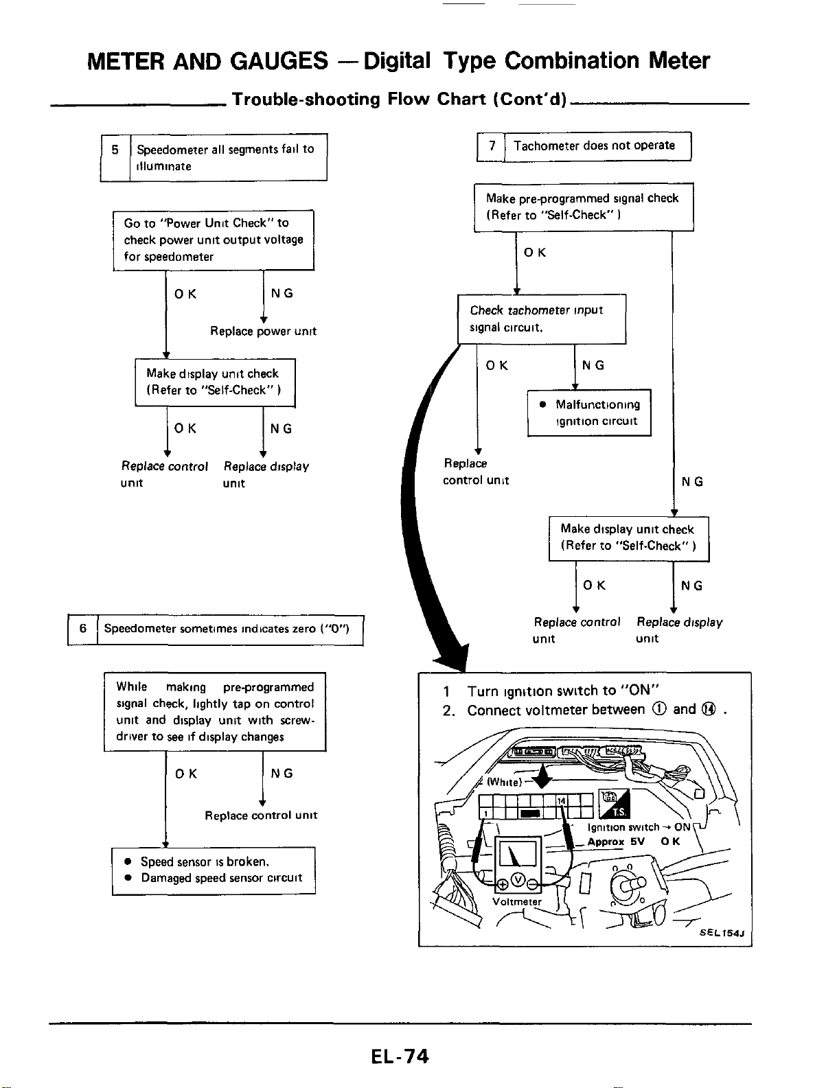
6
~
Speedometer
all
segments fail to
illuminate
Speedometer sometimes indicates zero
("0")
check power unit output voltage
for speedometer
lNG
OK
Replace power
unit
Make display unit check
(Refer to "Self-Check"
)
Replace control Replace display
unit unit
ING
OK
Replace
control
unit
I
7
I
Tachometer does not operate
I
Make pre-programmed signal check
(Refer to "Self-Check"
I
IOK
I
Check tachometer
input
signal circuit.
NG
T
Make display unit check
(Refer to "Self-Check"
)
NG
Replace control Replace display
1
Turn ignition switch
to
"ON"
2.
Connect voltmeter between
@
and
@
.
EL-74
METER
AND
GAUGES
-
Digital
Type
Combination
Meter
Trouble-shooting
Flow
Chart (Cont'd)
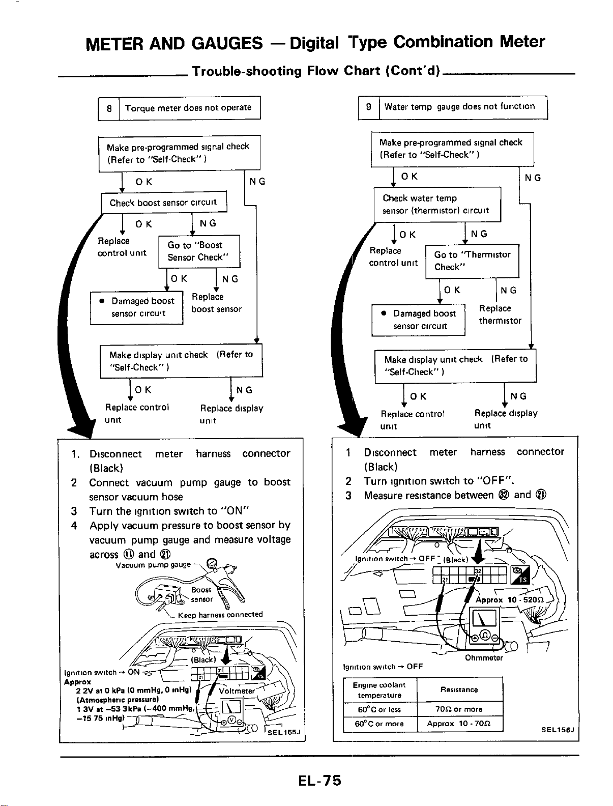
8
Torque meter does not operate
Make pre-programmed signal check
(Refer to "Self-Check"
1
Check boost sensor CirCUit
70$2
or
more
EQ"C0r
ierr
I
60°C
or
more
Approx
10.70$2
Go
to "Boost
Replace
v
Make display unit check (Refer to
"Self-Check"
)
OK
NG
Replace control Replace display
unit
unit
-
1.
Disconnect meter harness connector
2
Connect vacuum pump gauge to boost
3
4
(Black)
sensor vacuum hose
Turn the ignition switch to
"ON"
Apply vacuum pressure to boost sensor by
vacuum pump gauge and measure voltage
across
0
and
@
vacuum
pump
gauge
\&
'"
'L
~esp
harness
connected
-
Ignition
swltch
-+
Approx
2 2V
at
0
kPa
(0
rnmHg.
IAtrnorpheric prarrur
13Vat-533k
I
9
I
Water
temp gauge doer not function
1
Make pre-programmed signal check
(Refer to "Self-Check"
)
sensor (thermistor) circuit
Make display unit check (Refer to
Replace display
unit
1
Disconnect meter harness connector
2
3
(Black)
Turn ignition switch to
"OFF".
Measure resistance between
@
and
@
Ignition
switch-
OFF
Resistance
Engine
coolant
r
temverature
EL-75
METER AND GAUGES
-
Digital Type Combination Meter
Trouble-shooting Flow Chart (Cont'd)
I
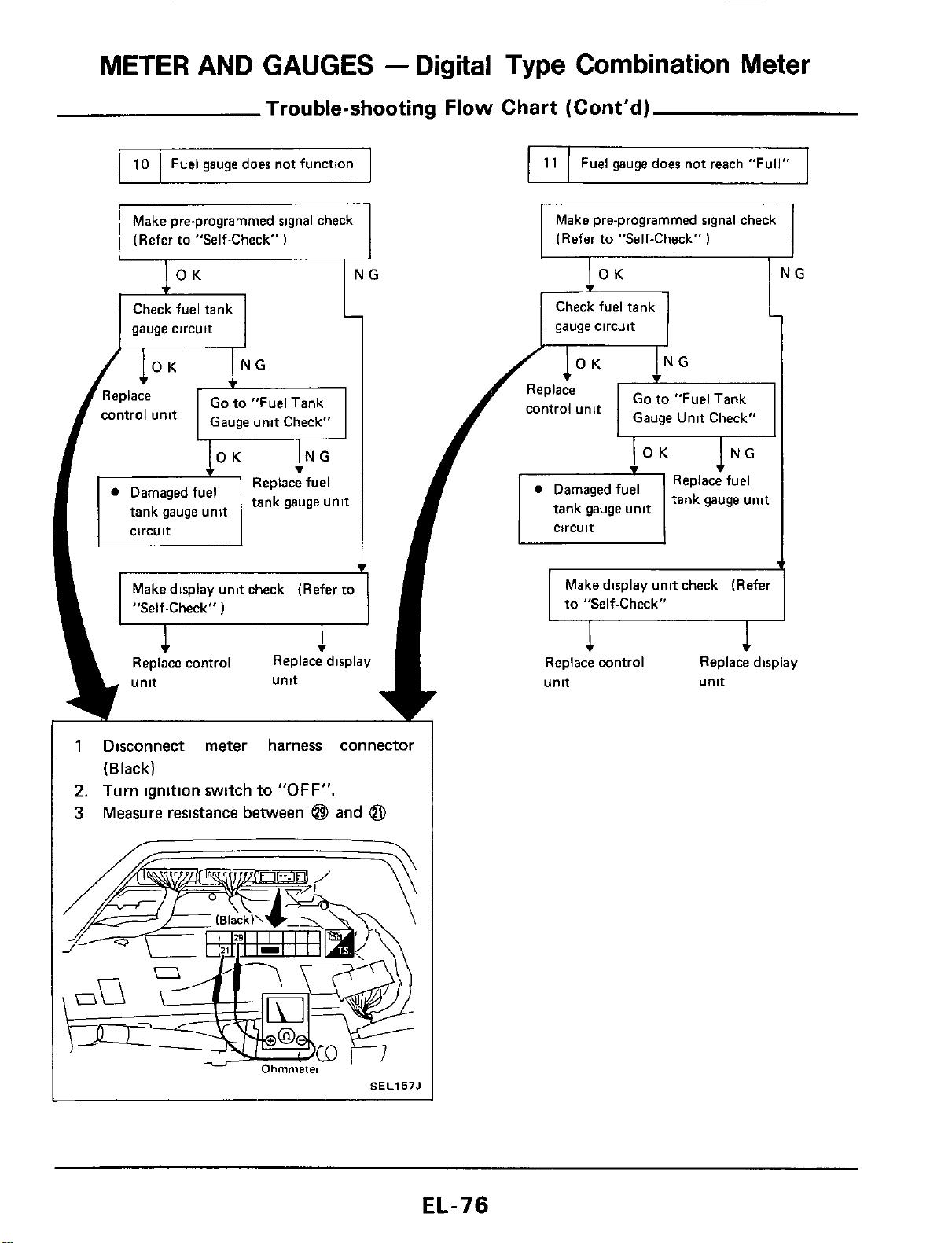
10
I
Fuel gauge does not function
I
I
11
I
Fuel gauge does not reach "Full"
I
Make pre-programmed signal check
(Refer to "Self-Check"
1
Make pre-programmed signal check
(Refer to "Self-Check"
)
gauge circuit
Check fuel tank
gauge circuit
1
Disconnect meter harness connector
(Black)
2.
Turn ignition switch to
"OFF".
3
Measure resistance between
@
and
@
SEL157J
METER
AND GAUGES
-
Digital
Type
Combination
Meter
Trouble-shooting
Flow
Chart (Cont'd)
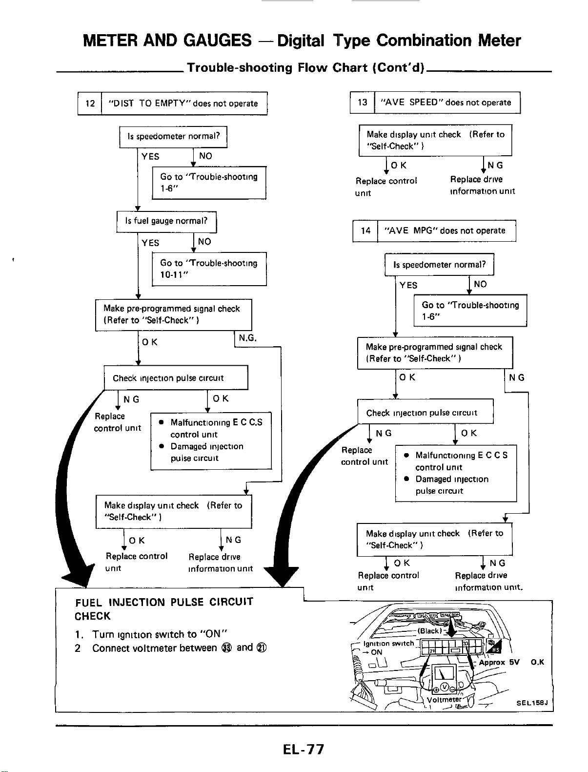
13
"AVE
SPEED"does not operate
Go
to 'Trouble-shooting
Is
fuel gauge normal?
12
10-11"
"DIST TO EMPTY"does not operate
Make pre-programmed signal check
(Refer to "Self-Check"
)
14
IOK
"AVE
MPG"does not operate
-1
Check injection pulse circuit
Make display unit check (Refer to
I
"Self-Check"
)
1N
Replace control Replace drive
unit
information unit
Is
speedometer normal?
Go
to "Trouble-shooting
Make pre-programmed signal check
(Refer to "Self-Check"
.-
Check injection pulse circuit
Replace
control unit
Malfunctioning
E
C
C.S
Damaged injection Replace
control unit
pulse circuit control unit
control unit
pulse circuit
Damaged injection
Make display unit check (Refer to
"Self-Check"
)
Make display unit check (Refer to
"Self-Check"
)
OK
NG
Replace control Replace drive
unit information unit
Replace control Replace drive
I
unit information unit.
FUEL
INJECTION
PULSE
CIRCUIT
CHECK
1.
Turn
ignition switch to
"ON"
2
Connect
voltmeter between
@
and
@
L
gni
ion
mi
c
V
0.K
SEL158J
EL-77
METER AND GAUGES
-
Digital
Type
Combination
Meter
Trouble-shooting
Flow
Chart (Cont'd)
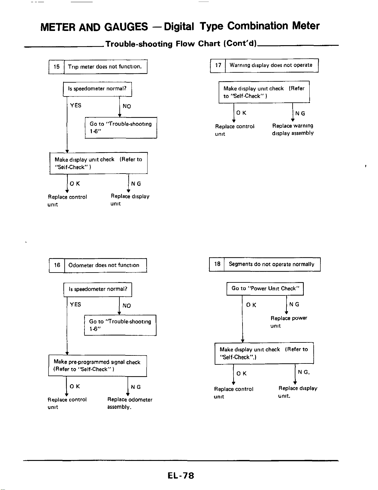
17
I
15
I
Trip meter does not function.
1
Warning display does not operate
Is
speedometer normal?
Go
to "Trouble-shooting
18
Segments
do
not operate normally
Make display unit check (Refer
to "Self-Check"
1
16
Replace warning
display assembly
lo
Replace control
unit
Odometer does not function
Make display unit check (Refer to
"Self-Check"
I
,
IN
Replace display
unit
Replace control
unit
I
Is
speedometer normal?
I
I
Go
to "Power Unit Check"
I
YES
e,
Go
to "Trouble-shooting
Make pre-programmed signal check
(Refer to "Self-Check"
)
Replace control Replace odometer
unit
assembly.
Replace power
,
unit
Make display unit check (Refer to
"Self-Check".)
Replace control Replace display
unit
unit.
EL-78
METER AND GAUGES
-
Digital Type Combination Meter
0
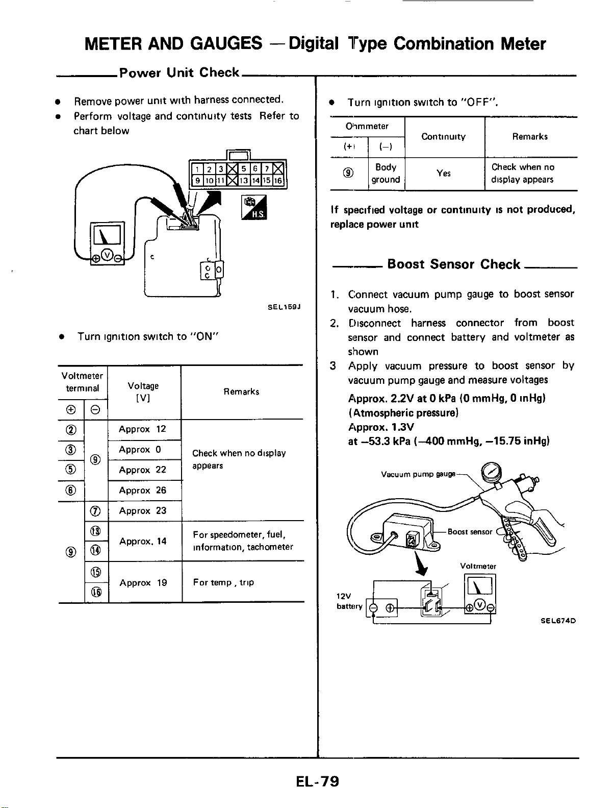
Power Unit Check
Remove power unit with harness connected.
0
Perform voltage and conttllulty
tests
Refer to
chart below
Approx
23
SELlSBJ
Turn ignition switch to
"ON"
Voltmeter
I
4
ri
Check when no display
0
Approx
22
appears
@
Approx
26
For speedometer, fuel,
information, tachometer
I
I
Approx
19
I
Fortemp,trip
~
Turn ignition switch to
"OFF".
Olimmeter
I I
Continuity Remarks
I
Check when no
ground display appears
If
specified voltage or continuity
is
not produced,
replace power unit
--
Boost Sensor Check
1.
Connect vacuum pump gauge to boost sensor
vacuum hose.
2.
Disconnect harness connector from boost
sensor and connect battery and voltmeter
as
shown
3
Apply vacuum pressure to boost sensor by
vacuum pump gauge and measure voltages
Approx.
2.2V
at
0
kPa
(0
mmHg,
0
inHg)
(Atmospheric pressure)
Approx.
1.3V
at
-53.3
kPa
(-400
mmHg,
-15.75
inHg)
Vacuum
pump
gauge
-
SEL674D
1
ZV
EL-79
METER
AND
GAUGES
-
Digital
Type
Combination Meter
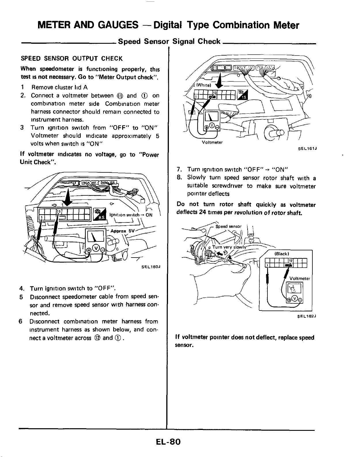
Speed Sensor Signal Check
SPEED SENSOR OUTPUT CHECK
When speedometer
is
functioning properly, this
test
is
not
necessary. Go
to
"Meter Output check".
1
Remove cluster
lid
A
2.
Connect
a
voltmeter between
0
and
@
on
combination meter side Combination meter
harness connector should remain connected to
instrument harness.
3
Turn ignition switch from
"OFF"
to
"ON"
Voltmeter should indicate approximately
5
volts when switch
is
"ON"
If
voltmeter indicates no voltage, go to "Power
Unit
Check".
SfLlSOJ
4.
Turn ignition switch
to
"OFF".
5
Disconnect speedometer cable from speed sen-
sor and remove speed sensor wlth harness con-
nected.
6
Disconnect combination meter harness from
instrument harness
as
shown below,
and
con-
nect
a
voltmeter across
@
and
@.
Voltmeter
SELlSlJ
7.
Turn ignition switch
"OFF"
-+
"ON"
8.
Slowly turn speed sensor rotor shaft with
a
suitable screwdriver to make sure voltmeter
pointer deflects
Do
not turn rotor shaft quickly as voltmeter
deflects
24
times
per revolution of rotor shaft.
SEL162J
If
voltmeter pointer does not deflect, replace
speed
sensor.
EL-80
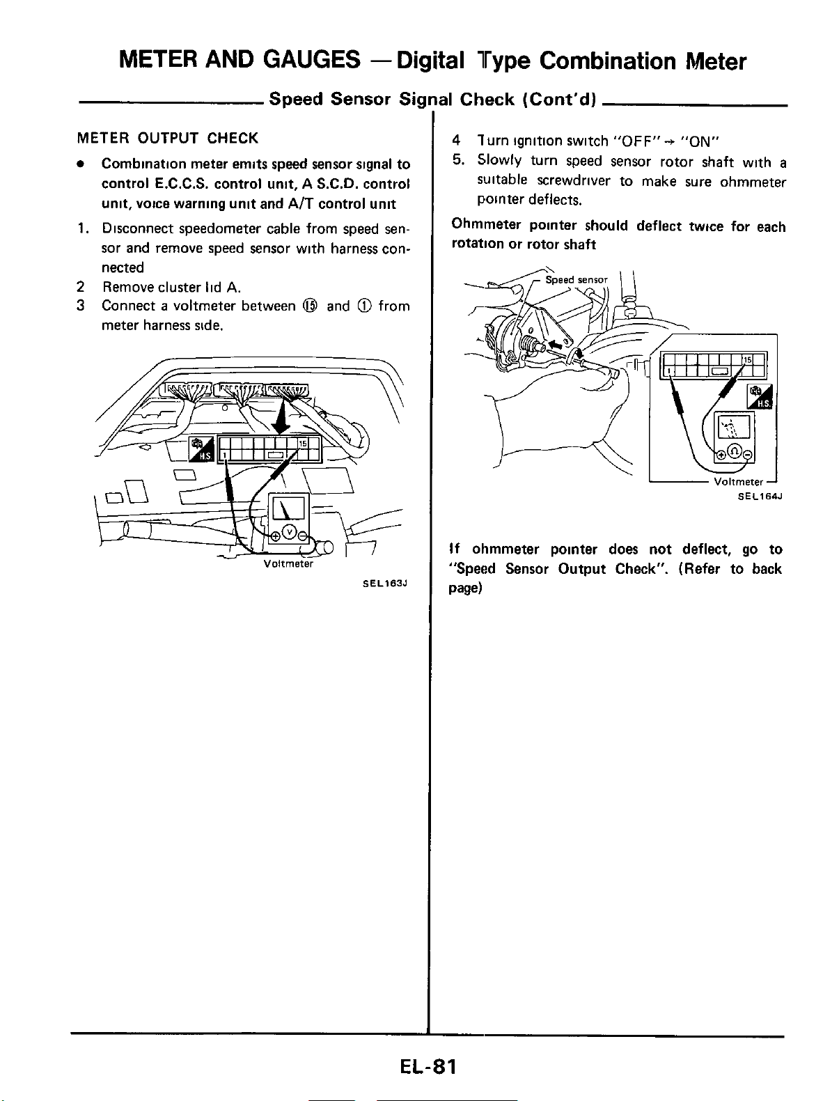
METER AND GAUGES
-
Digital Type Combination Meter
Speed Sensor
Si
METER
OUTPUT
CHECK
Combination meter emits speed sensor signal to
control E.C.C.S. control unit, A S.C.D. control
unit, voice warning unit
and
AIT control unit
1.
Disconnect speedometer cable from speed sen-
sor and remove speed sensor with harness con-
nected
2
Remove cluster lid
A.
3
Connect
a
voltmeter between
@I
and
@
from
meter harness side.
Voltmeter
SEL163J
31
Check (Cont'd)
4
lurn ignition switch
"OFF"+
"ON"
5.
Slowly turn speed sensor rotor shaft with
a
suitable screwdriver to make
sure
ohmmeter
pointer deflects.
Ohmmeter pointer should deflect twice for each
rotation or rotor shaft
-
Voitmeter-1
SEL164J
If
ohmmeter pointer does not deflect,
go
to
"Speed Sensor Output Check". (Refer to back
page)
EL-81
METER
AND GAUGES
-
Digital
Type
Combination Meter
00
00
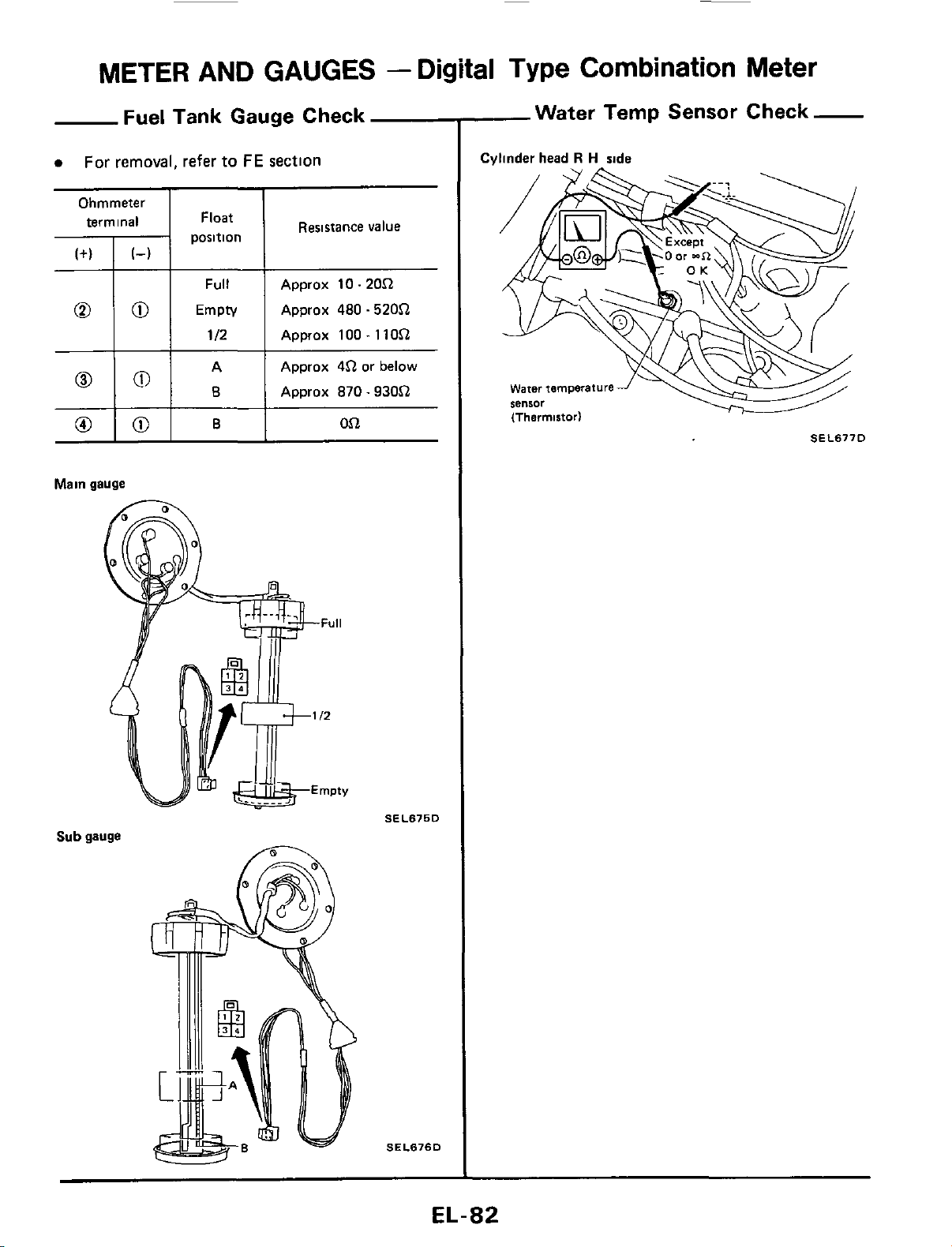
Fuel Tank Gauge Check
a
For removal, refer
to
FE
section
Full
Approx 10.20.Q
Empty Approx
480
.520.Q
112 Approx 100.11O.Q
A Approx
4.Q
or below
8
Approx
870.930.Q
Ohmmeter
I
I
0
101
B
Resistance value
pii::tn
1
Oi2
Main gauge
Sub
gauge
SEL675D
SEL676D
-Water Temp Sensor Check-
Cvlinder head
R
H
side
SEL677D
EL-82
METER
AND GAUGES -Needle Type
Combination
Meter
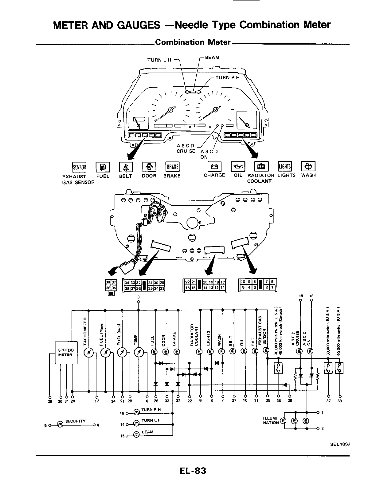
Combination Meter
ASCO
EXHAUST
FUEL
BELT
DOOR
BRAKE CHARGE OIL RADIATOR LIGHTS WASH
GAS SENSOR COOLANT
3
19
18
?
PP
TURN
R
H
SECURITY TURN
L
H
50
63
04
BEAM
15
ILLUMI
NATION
SEL103J
EL-83
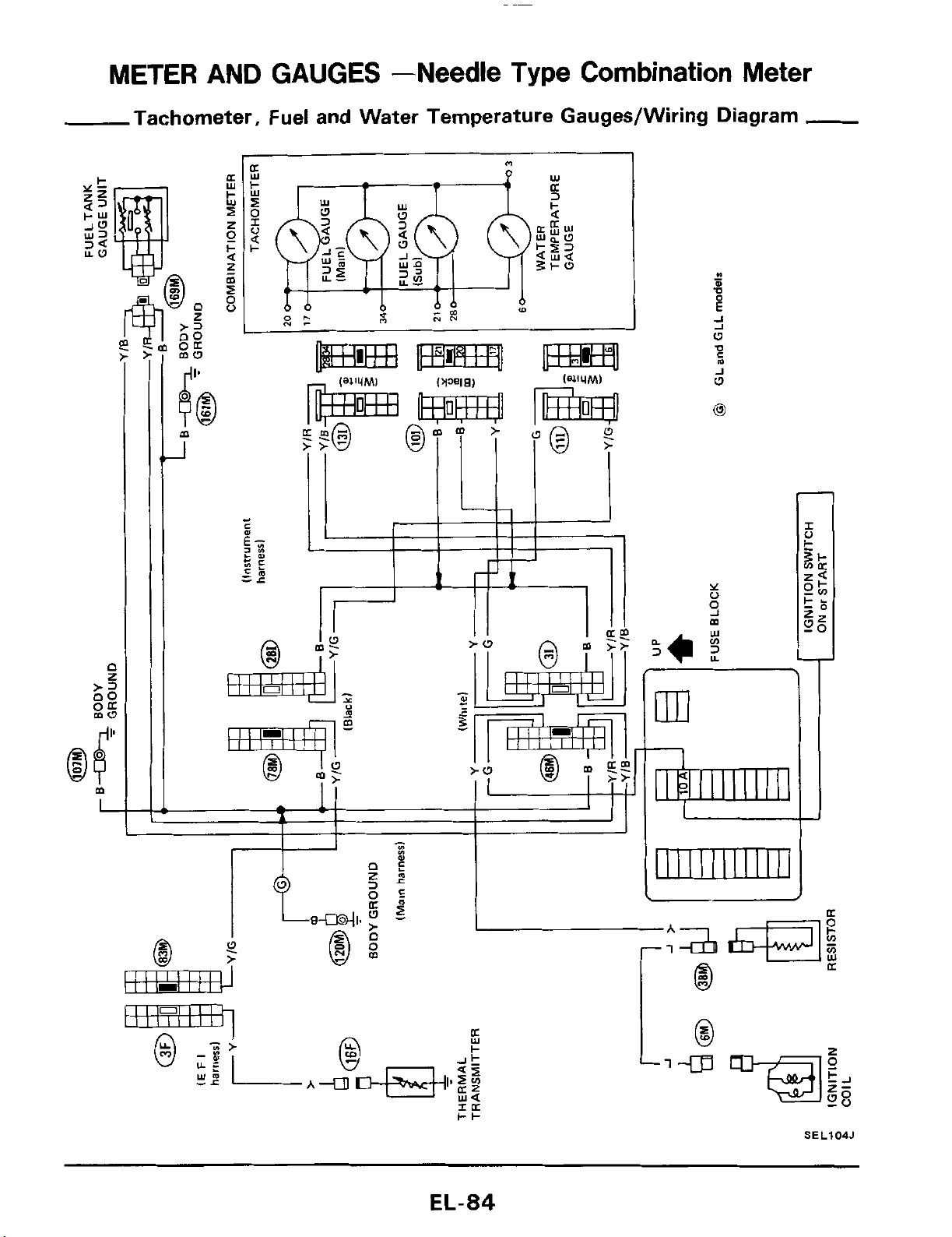
METER AND GAUGES -Needle Type
Combination
Meter
Tachometer, Fuel and Water Temperature Gauges/Wiring Diagram
-
J
W
0
1
SEL104J
EL-84
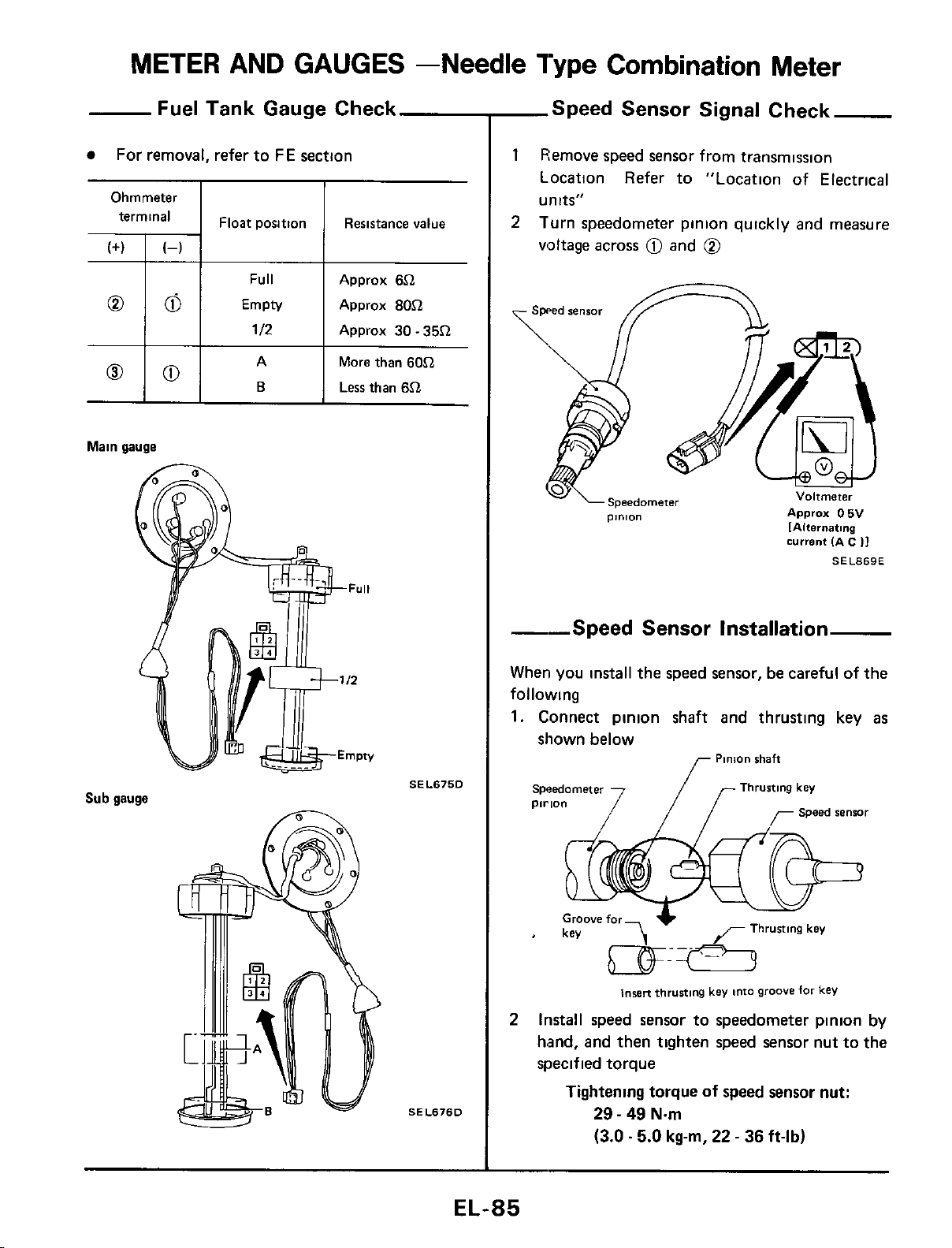
METER AND GAUGES -Needle Type Combination Meter
00
00
Fuel Tank Gauge Check
For removal, refer to
FE
section
Full Approx
6Cl
Empty Approx
80Cl
112
Approx
30
-
35Cl
A More than
60Cl
B
Less than
6.Q
Main gauge
Sub gauge
SEL675D
SEL676D
-Speed Sensor Signal Check
1
Remove speed sensor from transmission
Location Refer to "Location of Electrical
units"
Turn speedometer pinion quickly and measure
voltage across
0
and
@
2
current
IA
6
I]
SEL869E
--Speed Sensor Installation
When you install the speed sensor,
be
careful of the
following
1.
Connect pinion shaft and thrusting key
as
shown below
Pinion
shaft
Thrusting
key
pirion
r
Speed
renrar
IWBR
thrusting
key
into
groove
for
kev
2
Install speed sensor to speedometer pinion
by
hand, and then tighten speed sensor nut to the
specified torque
Tightening torque of
speed
sensor nut:
29
-
49
N.m
(3.0.5.0
kg-m,
22
-
36
ft-lb)
EL-85
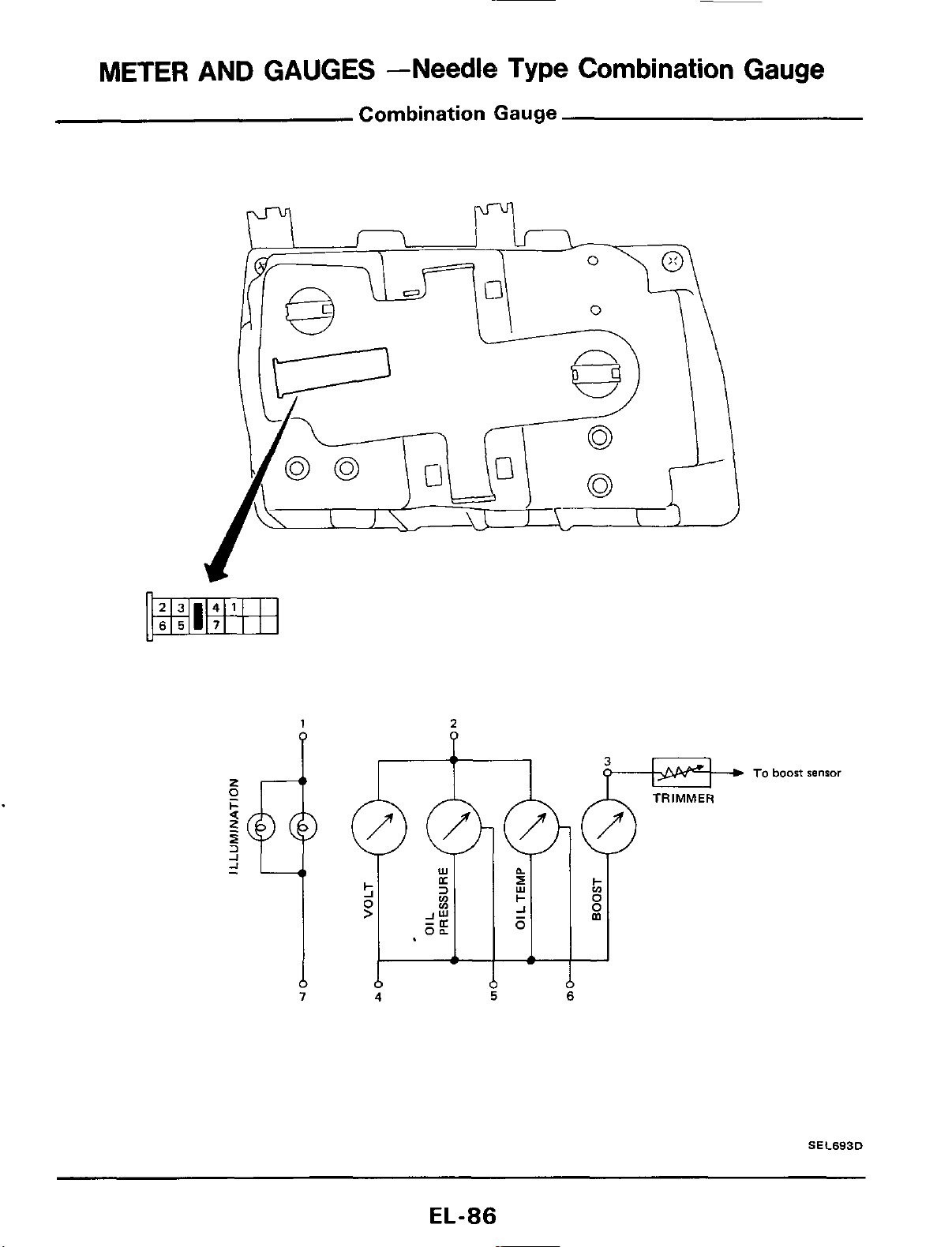
METER
AND
GAUGES
--Needle
Type Combination Gauge
Combination Gauge
1
2
4
5
6
To
boost
sensor
S
E
C693D
EL-86
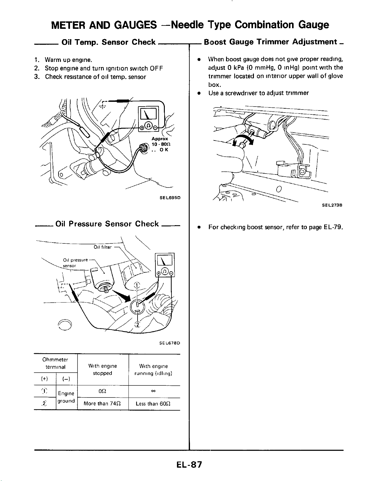
METER
AND GAUGES -Needle
Type
Combination Gauge
Oil
Temp. Sensor Check
1.
Warm up engine.
2.
Stop engine and turn ignition switch
OFF
3.
Check resistance
of
oil temp. sensor
SEL695D
-Oil
Pressure Sensor Check
-
-
011
filter
7
\\
SEL678D
Ohmmeter
terminal With engine With engine
stopped running (idling)
0.Q
m
Engine
71
ground
1
More than
74.Q
I
Less
than
6052
-
Bloost
Gauge Trimmer Adjustment
-
When
boost
gauge does not give proper reading,
adjust
0
kPa
(0
mmHg,
0
inHg) point with the
trimmer located on interior upper wall
of
glove
box.
lJse
a
screwdriver to adjust trimmer
SEL273B
f:or checking
boost
sensor, refer to page
EL-79.
EL-87
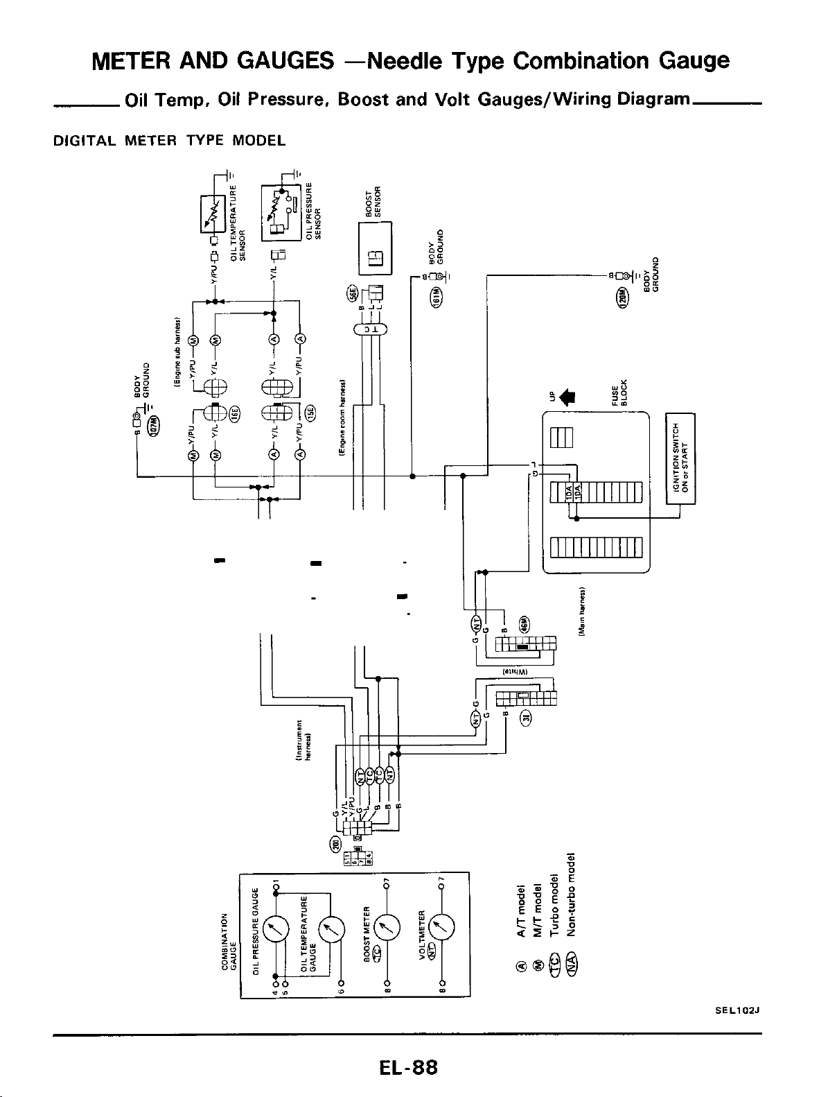
METER AND GAUGES -Needle Type
Combination
Gauge
Oil Temp, Oil Pressure, Boost and Volt Gauges/Wiring Diagram
DIGITAL
METER TYPE MODEL
SELIOZJ
EL-88
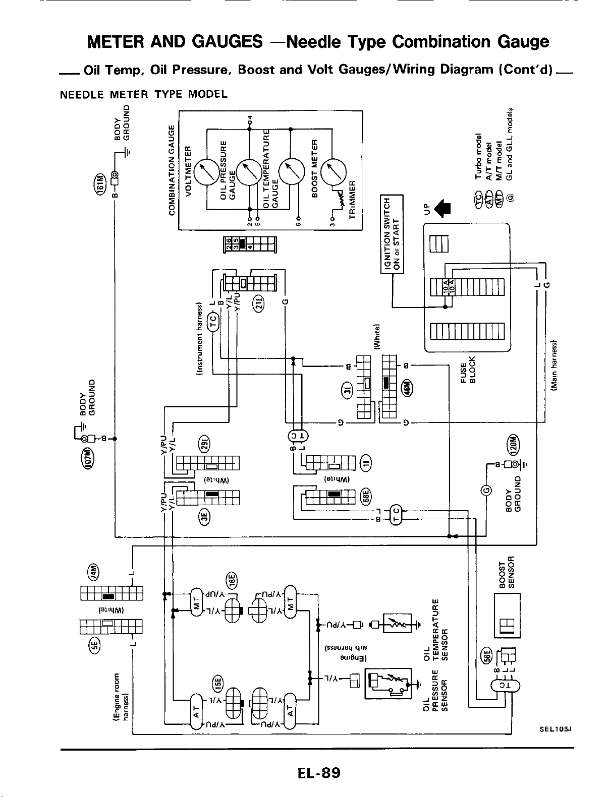
METER AND GAUGES -Needle Type
Combination
Gauge
-
Oil Temp,
Oil
Pressure,
Boost
and
Volt
Giauges/ Wiring Diagram (Cont'd)
-
NEEDLE METER TYPE MODEL
J
r
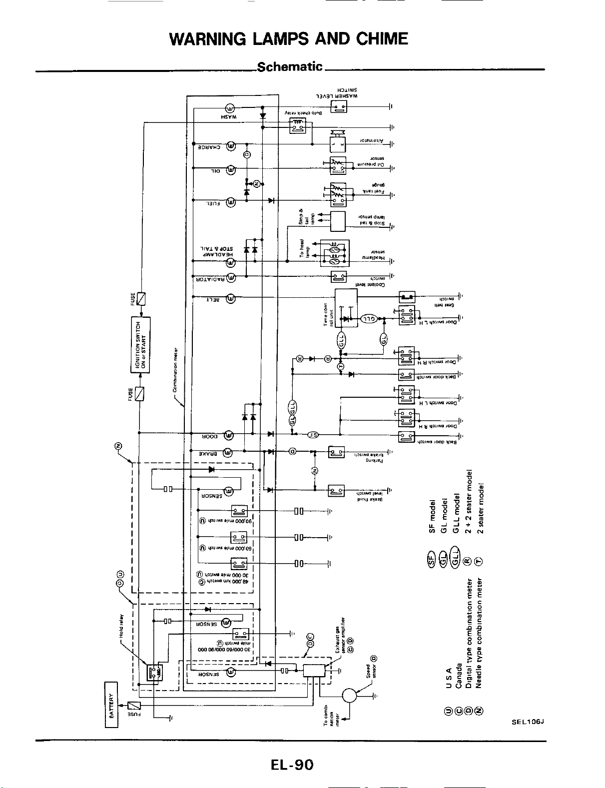
WARNING
LAMPS
AND
CHIME
Schematic
Y
LI
J
$1
\
I
I
I
I
I
I
I
I
I
I
I
U
EL-90
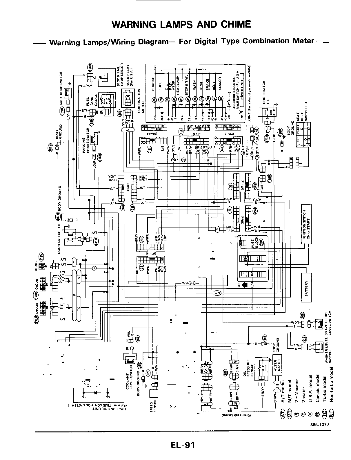
WARNING LAMPS AND CHIME
-
Warning Lamps/Wiring Diagram- For Digital Type Combination Meter-
-
.-
-
.
.T
.-
.
.
i-_
SEL107J
EL-91
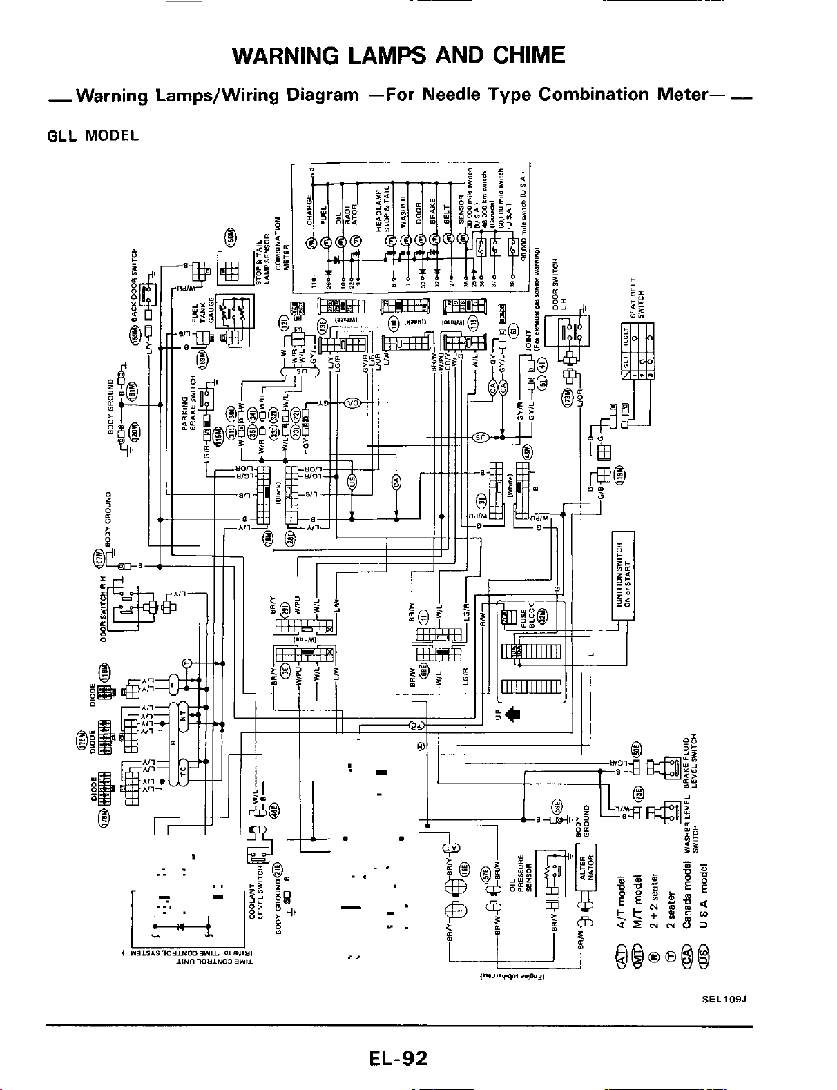
WARNING LAMPS AND
CHIME
-Warning Lamps/Wiring Diagram
-For
Needle Type Combination Meter-
-
GLL
MODEL
SELlOBJ
EL-92
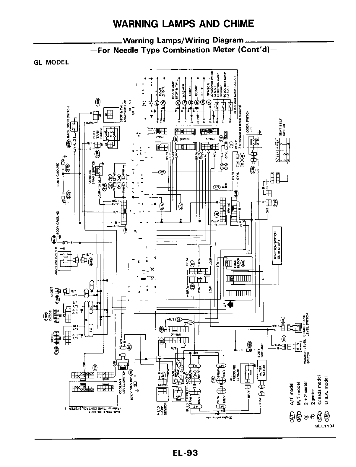
WARNING LAMPS AND
CHIME
Warning Lamps/Wiring Diagram
GL
MODEL
-
-For
Needle Type Combination Meter (Cont'd)-
I
SEL11W
EL-93
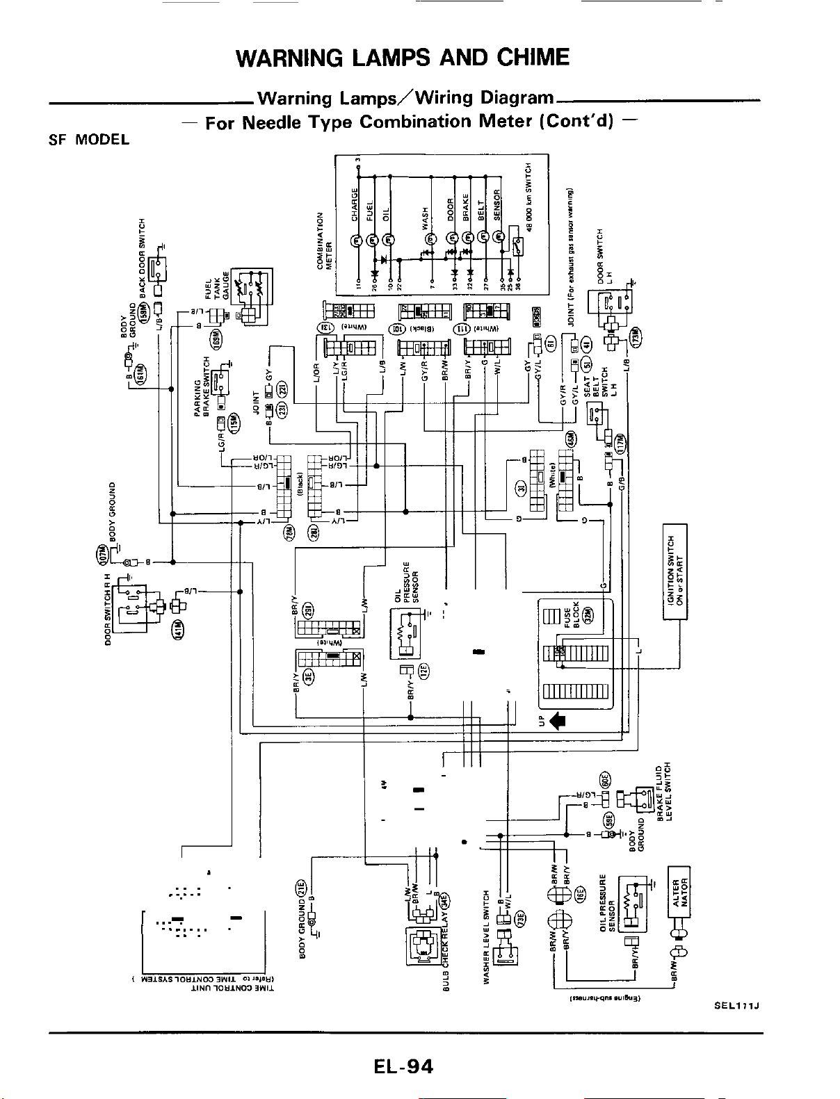
WARNING LAMPS AND CHIME
Warning LarnpdWiring Diagram
-
For Needle Type Combination Meter (Cont'd)
-
SF
MODEL
..
.
.....
SELlllJ
EL-94
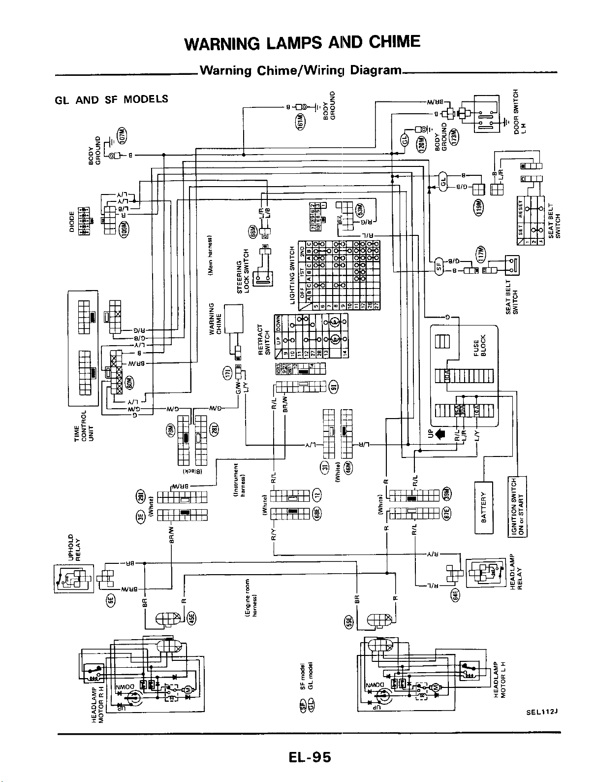
WARNING
LAMPS
AlND
CHIME
Warning Chime/Wiring Diagram
I
IL
1
mw
00
SEL
.11
ZJ
EL-95
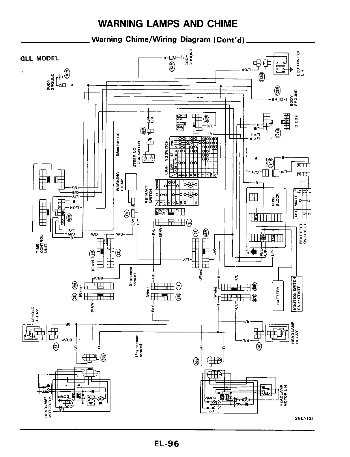
WARNING LAMPS AND CHIME
Warning Chime/Wiring Diagram (Cont'd)
GLL
MODEL
a-
-
00
EL-96
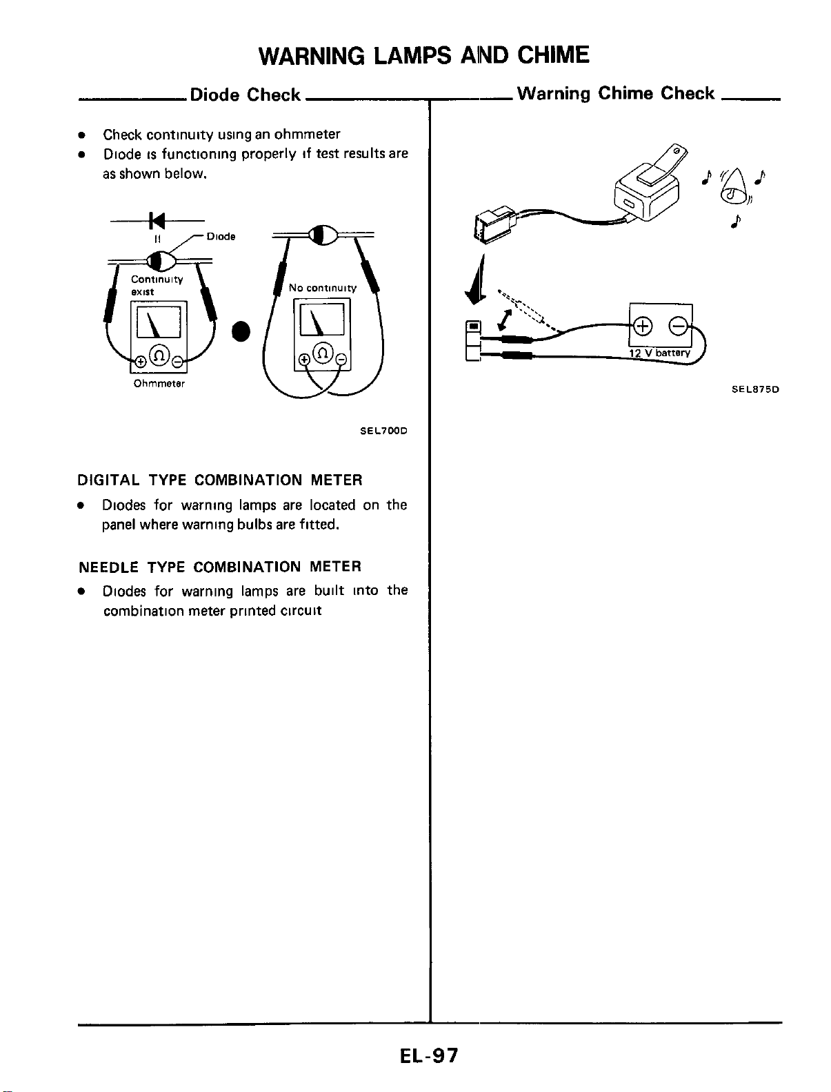
WARNING
LAMPS
AlND
CHIME
Diode Check
0
0
Check continuity using an ohmmeter
Diode
is
functioning properly if test results are
as shown below.
Continuity
Ohmmeter
No
continuity
(EJj
SEL700D
DIGITAL TYPE COMBINATION METER
0
Diodes for warning lamps are located on the
panel where warning bulbs are fitted.
NEEDLE TYPE COMBINATION METER
Diodes for warning lamps are built into the
combination meter printed circuit
--Warning Chime Check
P
&+
p-$
12
v
battery
d
SEL875D
EL-97
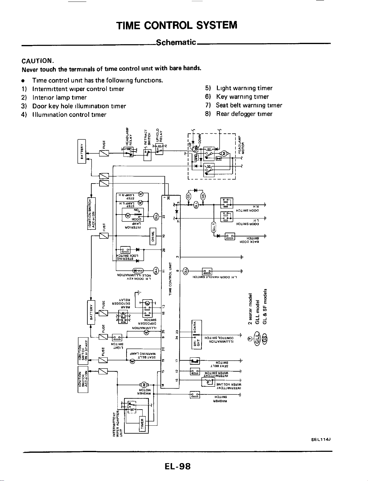
TIME
CONTROL
SYSTEM
Schematic
CAUTION.
Never touch the terminals
of
time control unit with bare hands.
0
1)
Intermittent wiper control timer
5)
2)
Interior lamp timer
6)
3)
Door key hole illumination timer
7)
4)
Illumination control timer
8)
Time control unit has the following functions.
Light warning timer
Key warning timer
Seat belt warning timer
Rear
defogger timer
EL-98
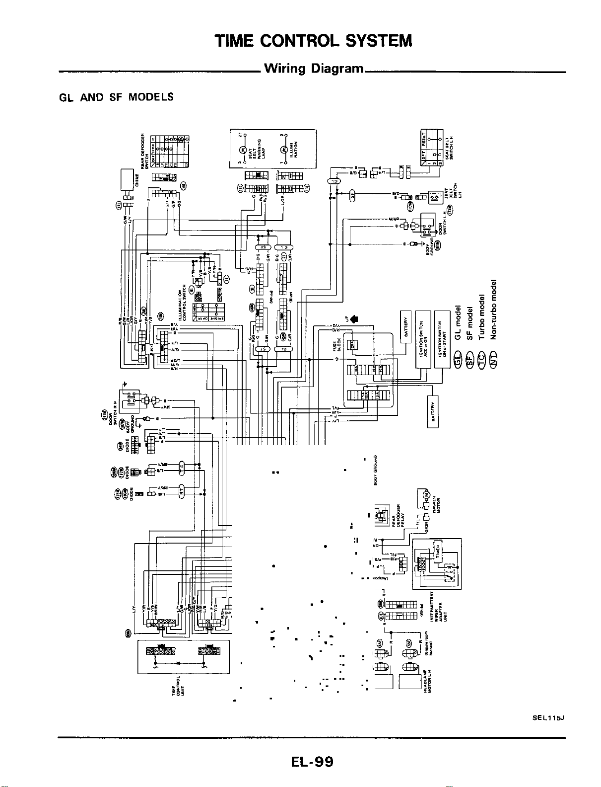
TIME
CONTROL
SYSTEM
Wiring
Diagriam
GL
AND
SF
MODELS
.-
>
I
..
._
..
..
.r
._
.
..
..
..
SEL115J
EL-99
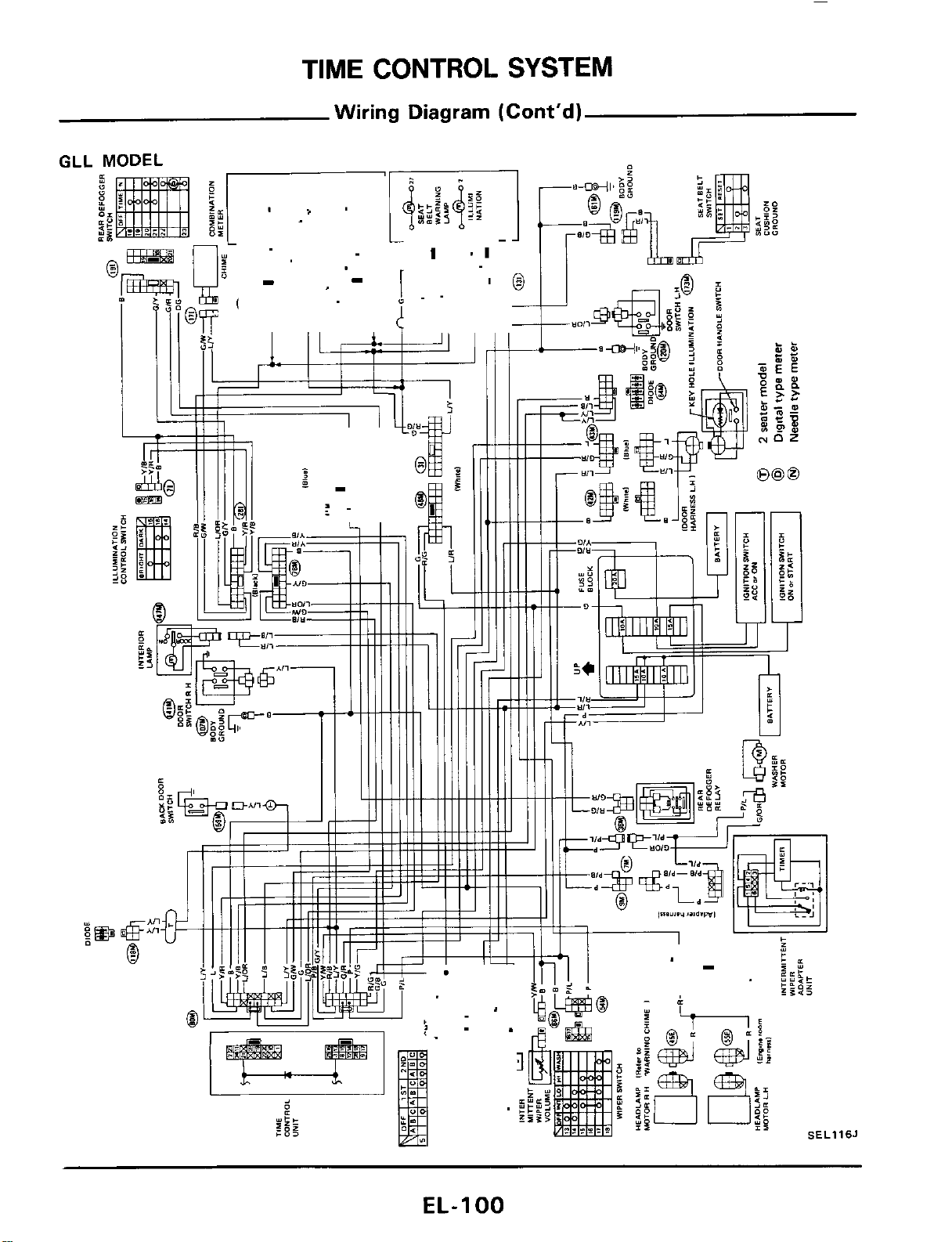
TIME
CONTROL
SYSTEM
Wiring
Diagram
(Cont'd)
GLL
Y
(1
P
.1
16J
EL-I
00
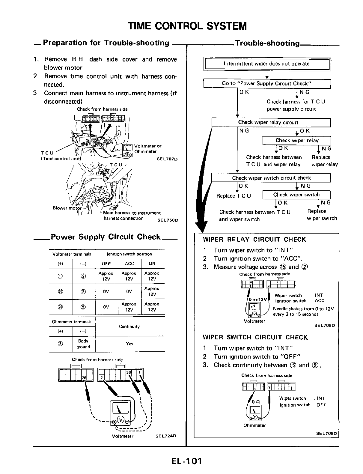
TIME CONTROL !SYSTEM
(+I
I
(-1
I
OFF
-
Preparation for Trouble-shooting
-
1.
Remove
R
H
dash side cover and remove
blower motor
2
Remove time control unit with harness con-
nected.
3
Connect main harness to instrument harness
(if
disconnected)
Check
from
harness
side
ACC
I
ON
Ii
TCU
-Power Supply Circuit Check-
Voltmeter
terminals
I
Ionition
switch
Dosition
12v
12v
Ohmmeter
terminals
COntlnUltY
I+)
I
(-1
SEL7240
-
Trouble-shooting
Intermittent wiper does
not
operate
power supply circuit
I
Check wioer relav circuit
I
Check wiper relay
Check harness between Replace
I
T
C
U
and wiper relay wiper relay
c
Check wiper switch circuit check
Check wiper switch
Check harness between
T
C
U
Replace
and wiper switch
*
wiper switch
3l
WIPER RELAY CIRCUIT CHECK
1
Turn wiper switch to "INT"
2
Turn ignition switch to "ACC".
3.
Measure voltage across
@
and
@
Check
from
harness
side
mm
Wiper
witch
INT
o-'2v
ignition
witch
ACC
Needle
shakes
from
0
to
12V
every
2
to
15
seconds
SEL7080
Voltmeter
6:
WIPER SWITCH CIRCUIT CHECK
1
Turn wiper switch to "INT"
2
Turn ignition switch
to
"OFF"
3.
Check continuity between
@
and
@.
Check
from
harness
ride
Wiper
switch
INT
ignition
switch
OFF
SEL709C
Ohmmeter
EL-I
01
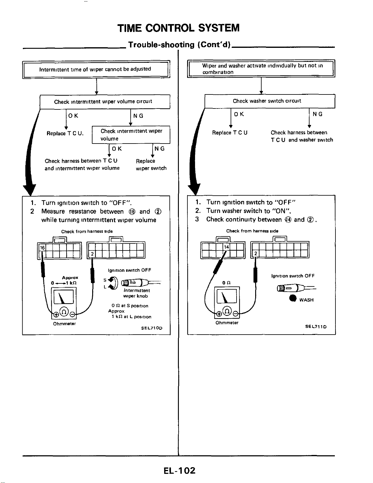
TIME CONTROL SYSTEM
Trouble-shooting
(Cont'd)
Intermittent time
of
wiper cannot be adjusted
Check intermittent wiper volume circuit
Check intermittent wiper
volume
Check harness between
T
C
U
and intermittent wiper volume
Replace
wiper switch
1.
Turn ignition switch to
"OFF".
2
Measure resistance between
@
and
@
while turning intermittent wiper volume
Check
from
harness
side
ignition
swtch
OFF
-
lntermirtent
wiper
knob
0
n
at
S
posmn
1
kR
at
L
posmon
Apprax
0-1
kR
Approx
Ohmmeter
SEL7100
1
Wiper and washer activate individually but not in
I
corn bination
I
I
Check washer switch circuit
I
lNG
Check harness between
T
C
U
and washer switch
I"
Replace
T
C
U
1.
Turn ignition switch to
"OFF"
2.
Turn washer switch to
"ON".
3
Check continuity between
@
and
@
.
Check
from
harness
iode
ignition
witch
OFF
WASH
I
Ohmmeter
SEL7110
I
EL-
1
02
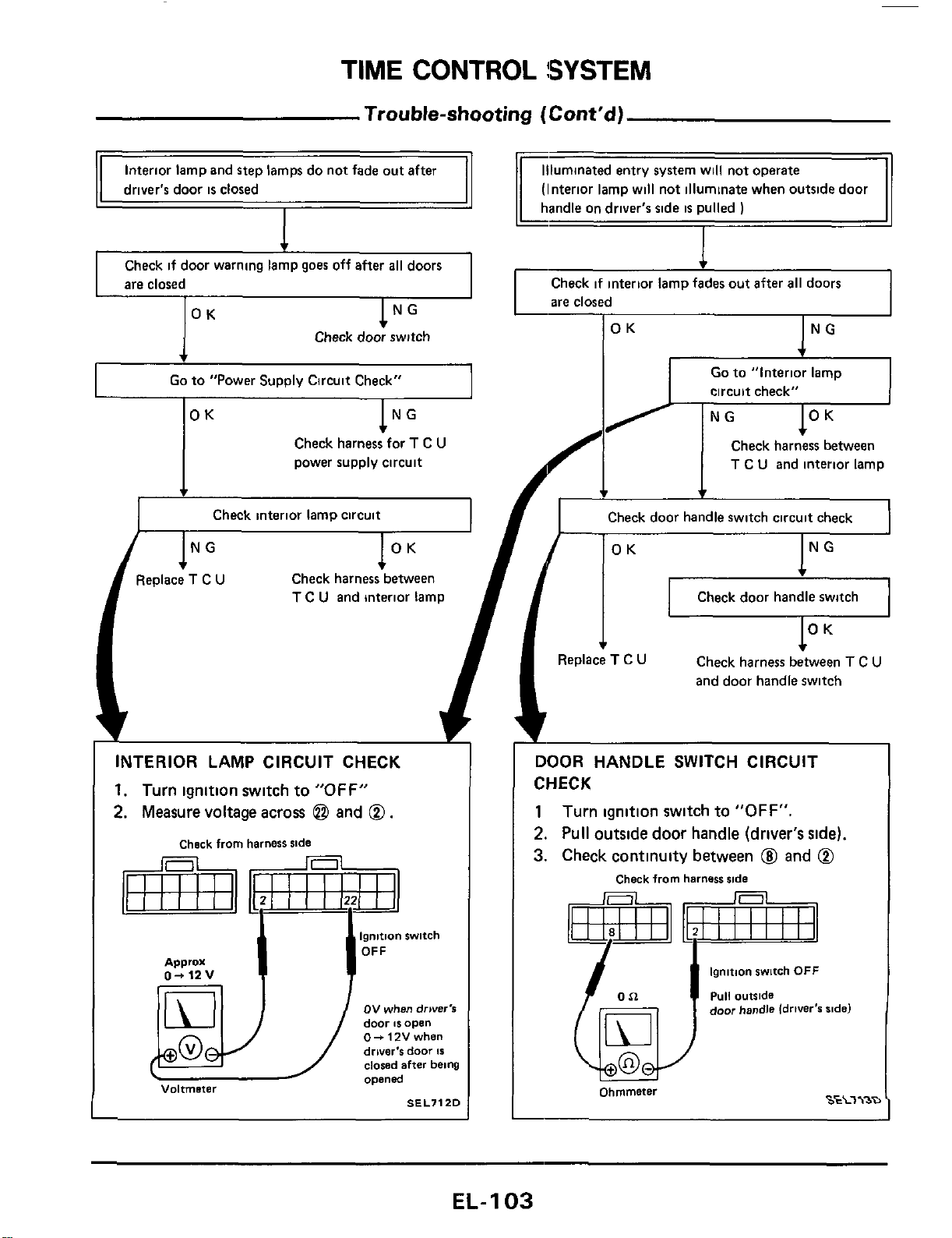
TIME
CONTROL
!SYSTEM
Trouble-shooting
(Cont'd)
11
Interior
lam
and
steD
lamm do not fade out after
11
driver's door
is
closed
Check if door warning lamp goes off after
all
doors
are closed
Check door switch
Go
to "Power Supply Circuit Check"
lNG
OK
Check harness for
T
C
U
power supply circuit
4
Check interior lamp circuit
(Interior lamp will not illuminate when outside door
Check if interior lamp fades out after
all
doors
are closed
OK
NG
c
circuit check"
Check harness between
T
C
U
and interior lamp
I
INTERIOR LAMP CIRCUIT CHECK
1.
Turn ignition switch to
"OFF"
2.
Measure voltage across
@
and
0.
Check
from
harness
side
ov
when
drwer's
door
IS
open
0-
12V
when
driver's
door
Is
dowd
after
being
opened
Voltmeter
SEL7120
+
f
Check door handle switch circuit check
OK
NG
Check door handle switch
I
*
t
3eplace
T
C
U
Check harness between
T
C
U
and door handle switch
DOOR HANDLE
SWITCH
CIRCUIT
CHECK
1
Turn ignition switch to
"OFF".
2.
Pull outside door handle (driver's side).
3.
Check continuity between
@I
and
0
Check
from
harness
side
ignition
switch
OFF
puli
outside
door
handle
idriver's
aide)
S€L7\3D
Ohmmeter
EL-
1
03
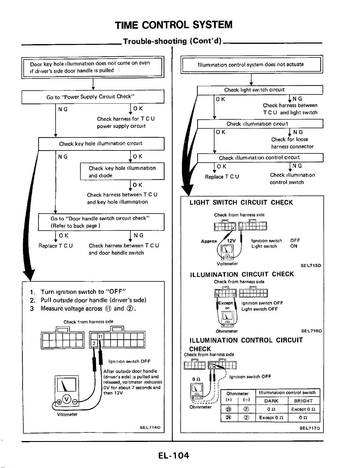
TIME
CONTROL
SYSTEM
Trouble-shooting (Cont'd)
NG
OK
Go
to "Power Supply Circuit Check"
I
Check harness for
T
C
U
power supply circuit
I
Check key hole illumination circuit
I
Check key hole illumination
and
diode
Check harness between
T
C
U
and key hole illumination
Go
to
"Door handle switch circuit check"
v
(Refer to back page
OK
NG
.
I
Replace
T
C
U
Check harness between
T
C
U
and door handle switch
1.
Turn
ignition
switch
to
"OFF"
2.
Pull
outside
door
handle
(driver's side)
3
Measure voltage
across
0
and
0.
Check
from
harness
side
ignition
switch
OFF
After
outside
door
handle
(drwer's
ride)
IS
pulled
and
released,
voltmeter
indicates
OV
far
about
7
seconds
and
then
12V
Voltmeter
SEL7140
Illumination control system does not actuate
Check Iiaht switch circuit
CNG
Check harness between
T
C
U
and light switch
Check illumination circuit
OK
NG
Check for loose
harness connector
v
Check illumination control circuit
OK
NG
Check illumination
control switch
Replace
T
C
U
LIGHT SWITCH CIRCUIT CHECK
Check
from
harness
side
Ignition
switch
OFF
Light
switch
ON
Voltmeter
SEL715C
ILLUMINATION CIRCUIT CHECK
Check
from
harness
ride
Except
Ignition
switch
OFF
Light
switch
OFF
Ohmmeter
M
SEL7ISI
ILLUMINATION CONTROL CIRCUIT
CHECK
:heck
from
harness
side
I
.-.____.-I
....__-
DARK
BRIGHT
Except
0
n
Ohmmeter
Except
0
n
SEL717D
EL-I
04
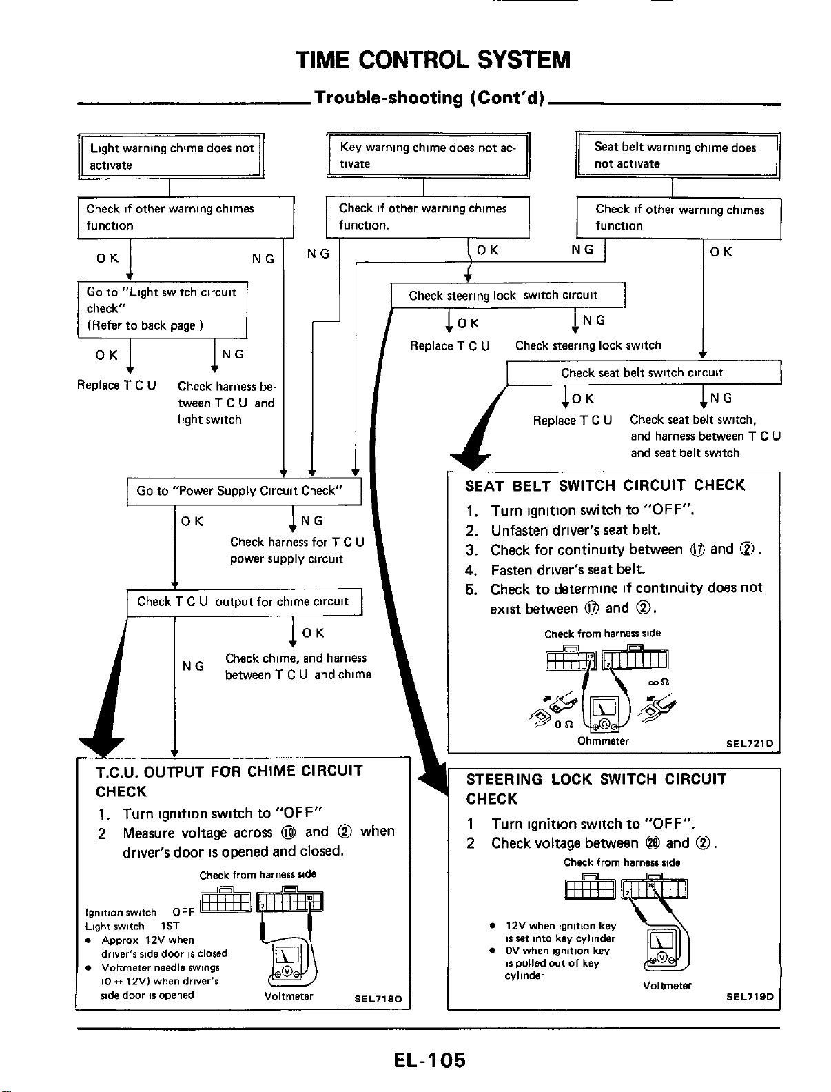
TIME
CONTROL
SYSTEM
Trouble-shooting
(Cont'd)
Light
warning chime does not
Check if other warning chimes
function
Go to "Light switch circuit
check"
(Refer to back
page
)
Replace
T
C
U
Check harness be-
tween
T
C
U
and
light switch
Seat belt warning chime does
tivate
not activate
Check
if
other warning chimes
function. function
NG
OK
I
Replace
T
C
U
Check
steering
lock switch
-
I
Go to "Power Supply Circuit Check"
I
OK
Check harness for
T
C
U
power supply circuit
I
Check
T
C
U
output for chime circuit
I
I
Check
seat
belt
switch circuit
I
Replace
T
C
U
Check
seat
belt switch,
and harness between
T
C
U
and seat belt switch
SEAT
BELT
SWITCH
CIRCUIT
CHECK
1.
Turn ignition
switch
to
"OFF".
2.
Unfasten
driver's
seat
belt.
3.
Check
for
continuity
between
0
and
0.
4.
Fasten driver's seat
belt.
5.
Check
to
determine
if
continuity
does
not
exist between
0
and
0.
Check
from
harness
side
ignition
switch
OFF
Light
switch
1ST
.
Apprax
12V
when
driver's
ride
door
IS
closed
Voltmeter
needle
swings
10
.+
12V)
when
driver's
%de
door
IS
opened
Voltmeter
SEL71RD
12V
when
tgnmon
key
IS
set
into
key
cylinder
OV
when
ignltlon
key
IS
pulled out
of
key
cylinder
Voltmeter
SEL719D
EL-I
05
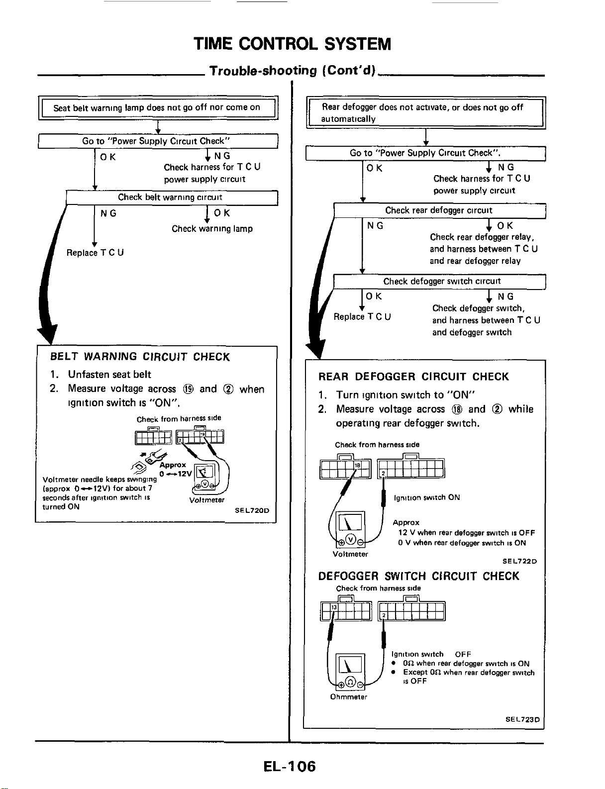
TIME
CONTROL
SYSTEM
Trouble-st
Seat belt warning lamp does not go off nor come on
4
I
Go
to "Power Supply Circuit Check"
Check harness for
T
C
U
power supply circuit
BELT WARNING CIRCUJT CHECK
1.
Unfasten
seat
belt
2.
Measure
voltage
across
@
and
@
when
ignition
switch
is
"ON".
check from harness side
Voltmeter needle keeps
winging
lapprox 0-1ZVI for abut7
seconds
after
ignition
witch
IS
turned
ON
Voltmeter
SEL7200
iny
(Cont'd)
Rear defogger does not
activate,
or does not go off
automatically
I
c
Go
to "Power Supply Circuit Check".
]OK
4
NG
I
Check harness for
T
C
U
power supply circuit
Check rear defogger circuit
1
OK
I
NG
Check rear defogger relay,
and harness between
T
C
U
and rear defogger relay
Check defogger switch circuit
4
NG
1
Check defogger switch.
and harness between
T
C
U
and defogger switch
REAR DEFOGGER CIRCUIT CHECK
1.
Turn
ignition
switch
to
"ON"
2.
Measure
voltage
across
@
and
@
while
operating
rear
defogger
switch.
Check from harness side
ignition switch
ON
Q4)
Voltmeter
Approx
12
V
when rear defogger witch
IS
OFF
0
V when rear defogger switch
1s
ON
SEL7220
DEFOGGER SWITCH CIRCUIT CHECK
Check from harness
ride
ignition witch OFF
0
On
when
rear
defogger switch
1s
ON
Except
On
when rear defogger switch
1s
OFF
Ohmmeter
SEL7230
EL-1
06
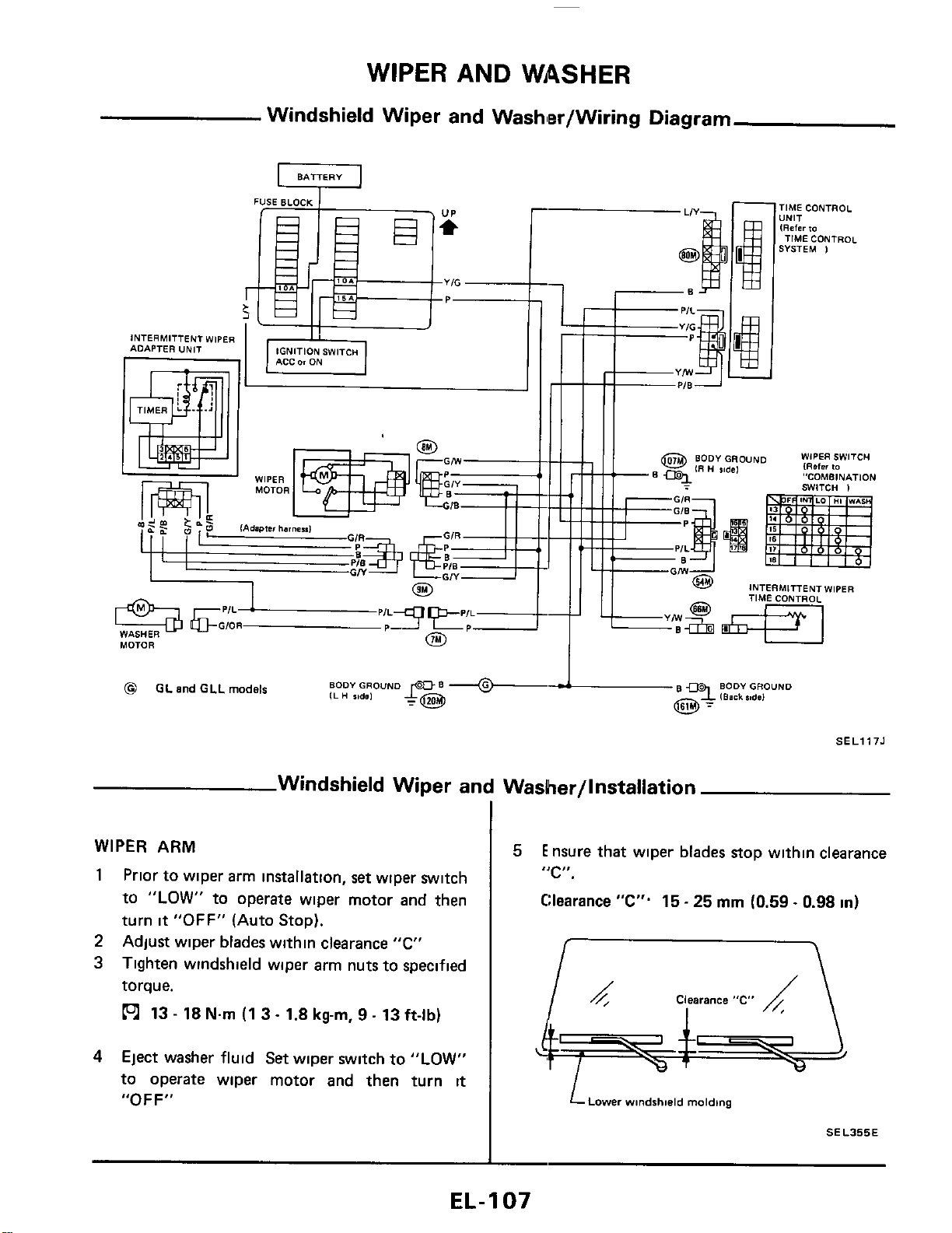
WIPER
AND
WASHER
Windshield Wiper and Washler/Wiring Diagram
U
BATTERY
YIG
-
IGNITION SWITCH
INTERMITTENT WIPER
ADAPTER UNIT
0
WASHER
MOTOR
-1ME CONTROL
,NIT
RaCr
to
TIME CONTROL
iVSTEM
1
INTERMITTENT
WIPER
TIME CONTROL
PER SWITCH
ster
10
'ITCH OMBINATION
I
BODY
GROUND
B
9
BODY
GROUND
~
I
IBask
%#de1
@
GL
and
GLL
models
SELl175
Windshield Wiper and Washer/lnstallation
WIPER
ARM
1
Prior to wiper arm installation,
set
wiper switch
to
"LOW"
to operate wiper motor and then
turn
it
"OFF"
(Auto Stop).
Adjust wiper blades within clearance
"C"
Tighten windshield wiper arm nuts to specified
torque.
13
-
18
Nm
(1 3
-
1.8
kg-m,
9
-
13
ft-lb)
2
3
4
Eject washer fluid Set wiper switch
to
"LOW"
to operate wiper motor and then turn
it
"OFF"
5
Ensure that wiper blades stop within clearance
"C".
Clearance
"C".
15
-
25
mm
(0.59
~
0.98
in)
LLDwer
windshield
molding
SEL355E
EL-
1
07
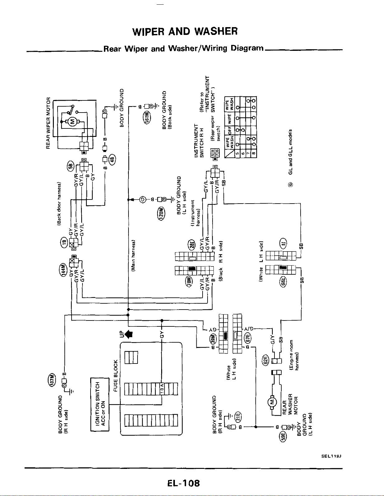
WIPER AND WASHER
Rear Wiper
and
Washer/Wiring Diagram
L
n
I
z
3
n
z
r%l
m
J
w
'I
SEL118J
EL-I
08
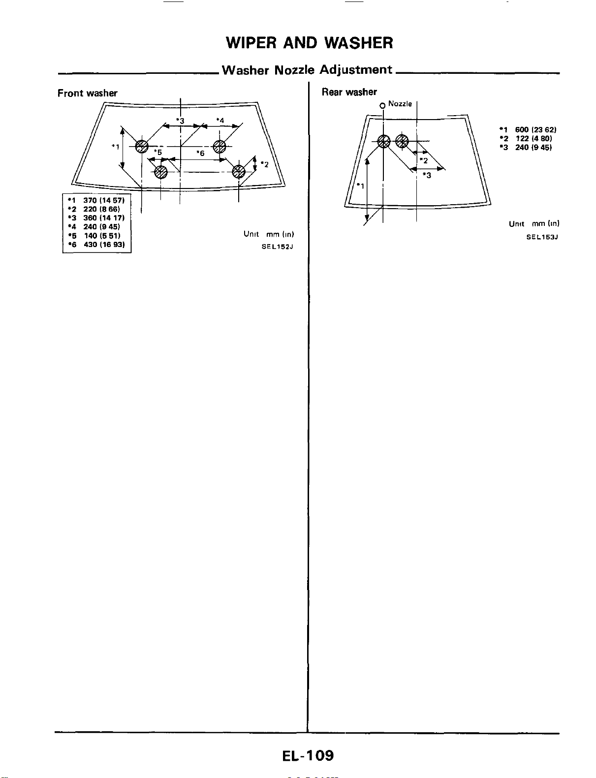
WIPER
AND
WASHER
Washer Nozzle Adjustment
Front
washer
'2
220
(8661
*3 360(1417)
*4 240 (9451
1%
140(551)
1
*6
430d693)
Unit
mm
(in)
SEL15ZJ
Rear washer
9
Nozzle
I
*1
600
12362)
'2
122(480)
*3
240(945)
Unit
mm
(in1
SEL153J
EL-
1
09
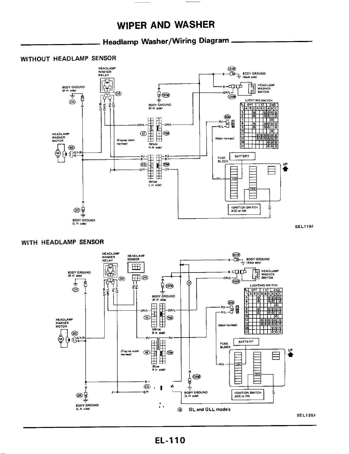
WIPER AND WASHER
Headlamp Washer/Wiring Diagram
WITHOUT HEADLAMP
SENSOR
WITH HEADLAMP
SENSOR
I
L
"'-r
BODY
GROUND
ILH
lid.1
SELlI9J
I
I
I.
0
GL
and
GLL
models
SELIZOJ
EL-1
10
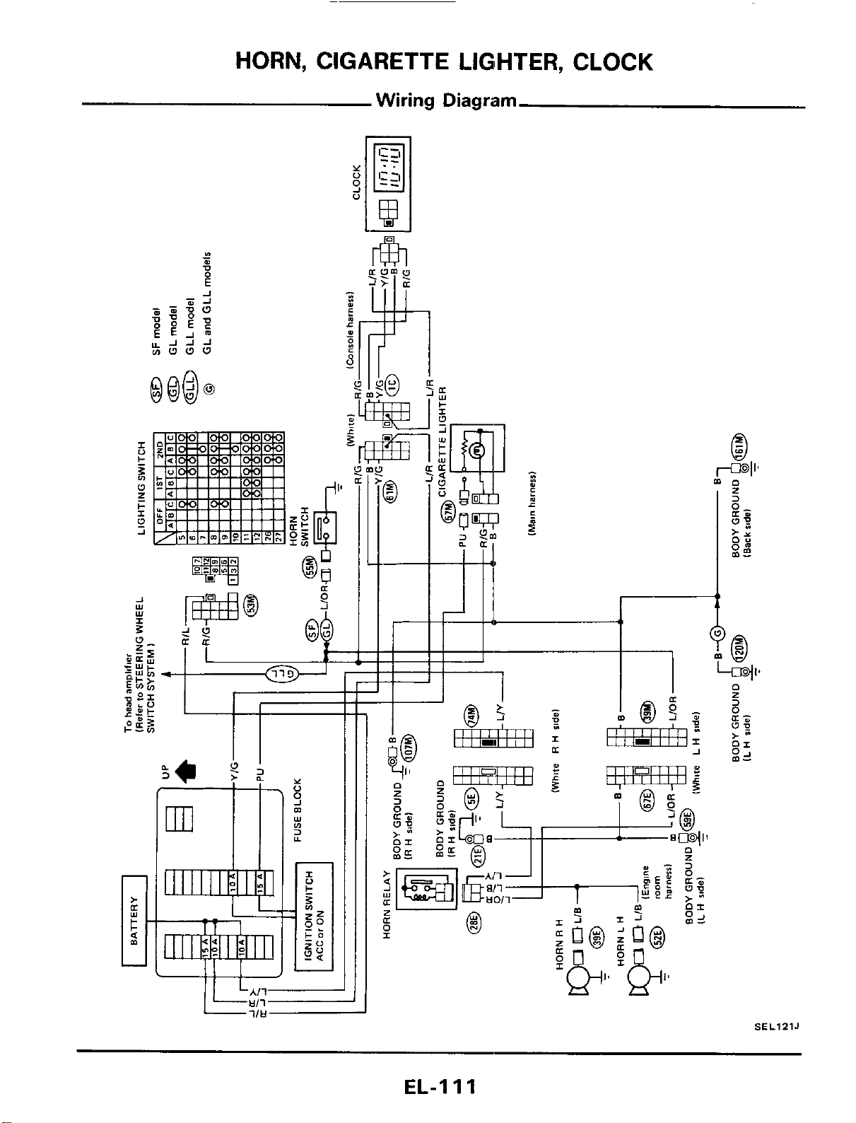
HORN, CIGARETTE LIGlHTER, CLOCK
Wiring Diagram
-
SEL12lJ
EL-I
11
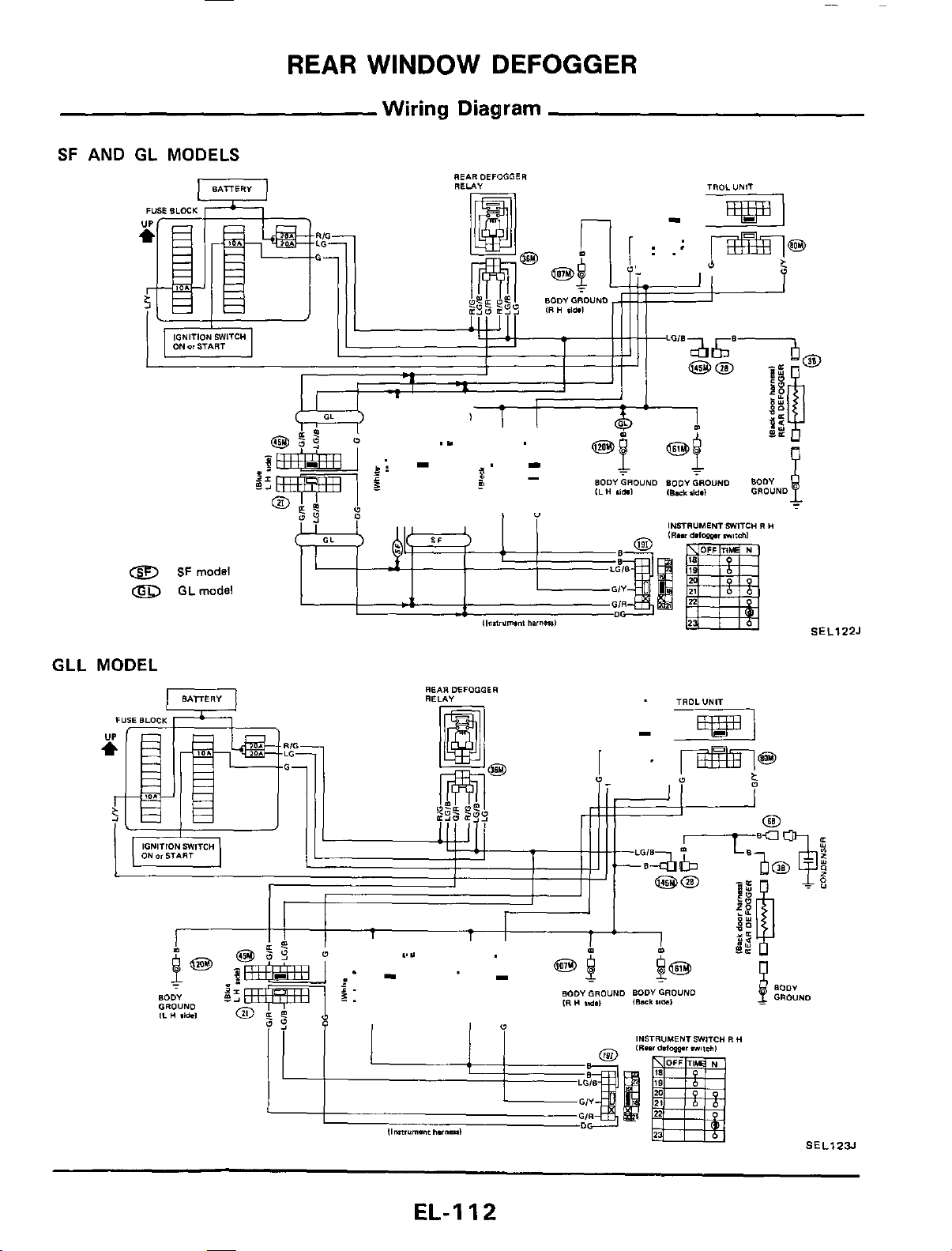
REAR
WINDOW
DEFOGGER
Wiring Diagram
SF
AND
GL MODELS
REARDEFOGGER
RELA"
INSTRUMENT
JWITC"
R
H
8
SF
mods!
0
GLmodel
SEL122J
GLL
MODEL
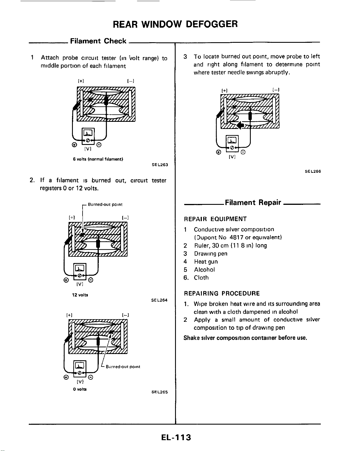
REAR
WINDOW
DEFOGGER
Filament Check
1
Attach probe circuit tester (in tolt range) to
middle portion of each filament
w
[VI
6
volts
[normal
filament)
SEL263
2.
If
a
filament
is
burned out, circuit tester
registers
0
or
12
volts.
12
Volts
[+I
[-I
Burned-out
point
[VI
0
"Olts
SE
L264
SEL265
3
To
locate burned out point. move probe to left
and right along filament to determine point
where
tester
needle swings abruptly.
SEL266
_.
Filament Repair
REPAIR EQUIPMENT
1
Conductive silver composition
(!3upont
No
4817
or equivalent)
2
Fhler,
30
cm
(1
1
8
in)
long
3 Drawing pen
4
Heat gun
5
Alcohol
6.
Cloth
REPAIRING PROCEDURE
1,
Wipe broken heat wire and
its
surrounding area
clean with
a
cloth dampened in alcohol
2
Apply
a
small
amount of conductive silver
cornposition to tip
of
drawing pen
Shake silver composition container before
use.
EL-I
13

REAR
WINDOW DEFOGGER
Filament
Rc
3
Place ruler on
glass
along broken line Deposit
conductive silver composition
on
break with
drawing pen Slightly overlap existing
heat
wire
on both sides [preferably
5
mm
(0.20
in)]
of
the break
--
:E
00
imtmr
,
Break
Heat
wire
Ill/
I I
:/
Orawing pen
BE540
4
After repair
has
been completed, check re-
paired wire for continuity. This check
should
be conducted
10
minutes after silver composi-
tion
is
deposited
Do
not touch
repaired area while
test
is
being con-
ducted.
r
Repaired
point
SELOlZD
I
+
SELOlZD
iir
(Cont'd)
5.
Apply
a
constant stream of hot
air
directly
to
the repaired area
for
approximately
20
minutes
with
a
heat gun. A minimum distance
of
3
cm
(1
2
in) should
be
kept between repaired
area
and hot
air
outlet.
If
a
heat
gun
is
not available,
let the repaired area dry for
24
hours
,
r
Repaired
point
SEL013D
EL-I
14
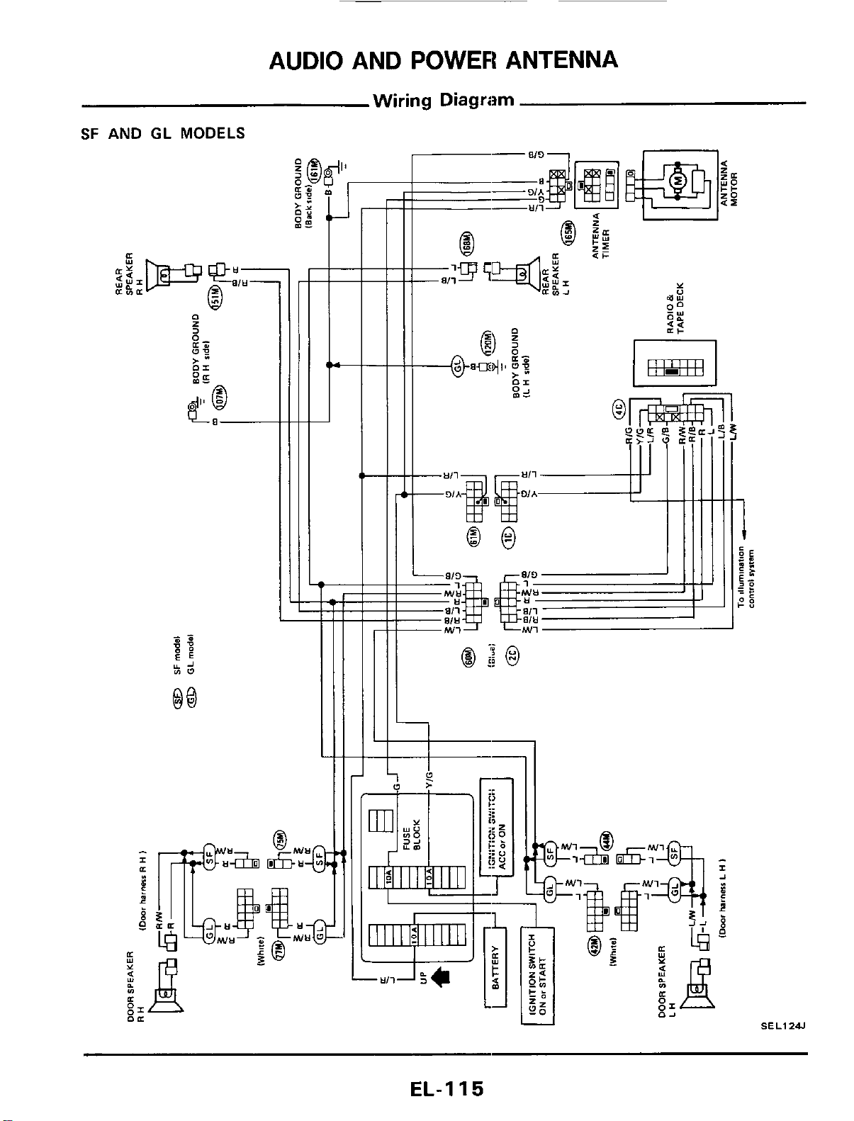
AUDIO AND POWER ANTENNA
Wiring Diagram
SF
AND
GL
MODELS
B
Q
tt
I-
+--
I
SEL1241
EL-I
15
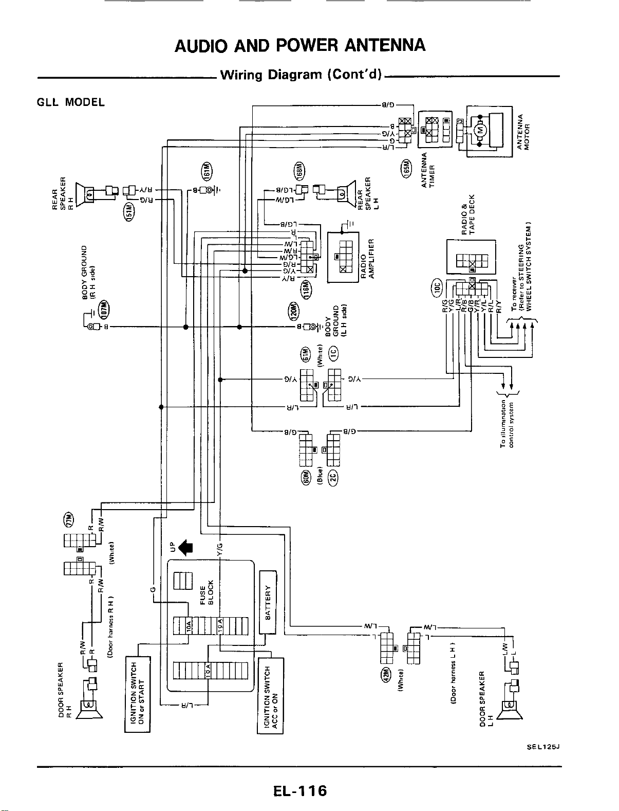
AUDIO AND
POWER
ANTENNA
Wiring Diagram (Cont'd)
GLL
MODEL
SEL125J
EL-I
16
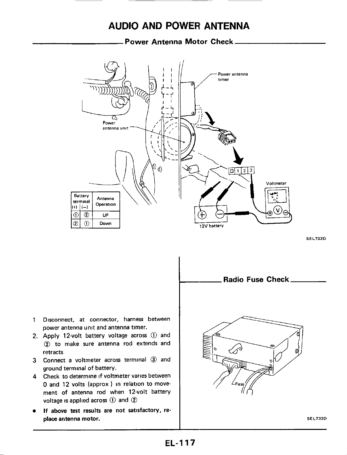
AUDIO AND POWER ANTENNA
Power Antenna Motor Check
1 Disconnect,
at
connector, harness between
power antenna unit and antenna timer.
2. Apply 12-volt battery voltage across
@
and
@
to make sure antenna rod extends and
retracts
3
Connect
a
voltmeter acros terminal
0
and
ground terminal
of battery.
4
Check to determine
if
voltmeter
varies
between
0
and 12 volts (approx
)
in relation to move-
ment
of
antenna rod when 12-volt battery
voltage
is
applied across
@
and
@
If
above test results are not satisfactory,
re-
place antenna motor.
12V
batten/
-
Radi
SEL732D
Fuse
Check
SEL733D
EL-I
17
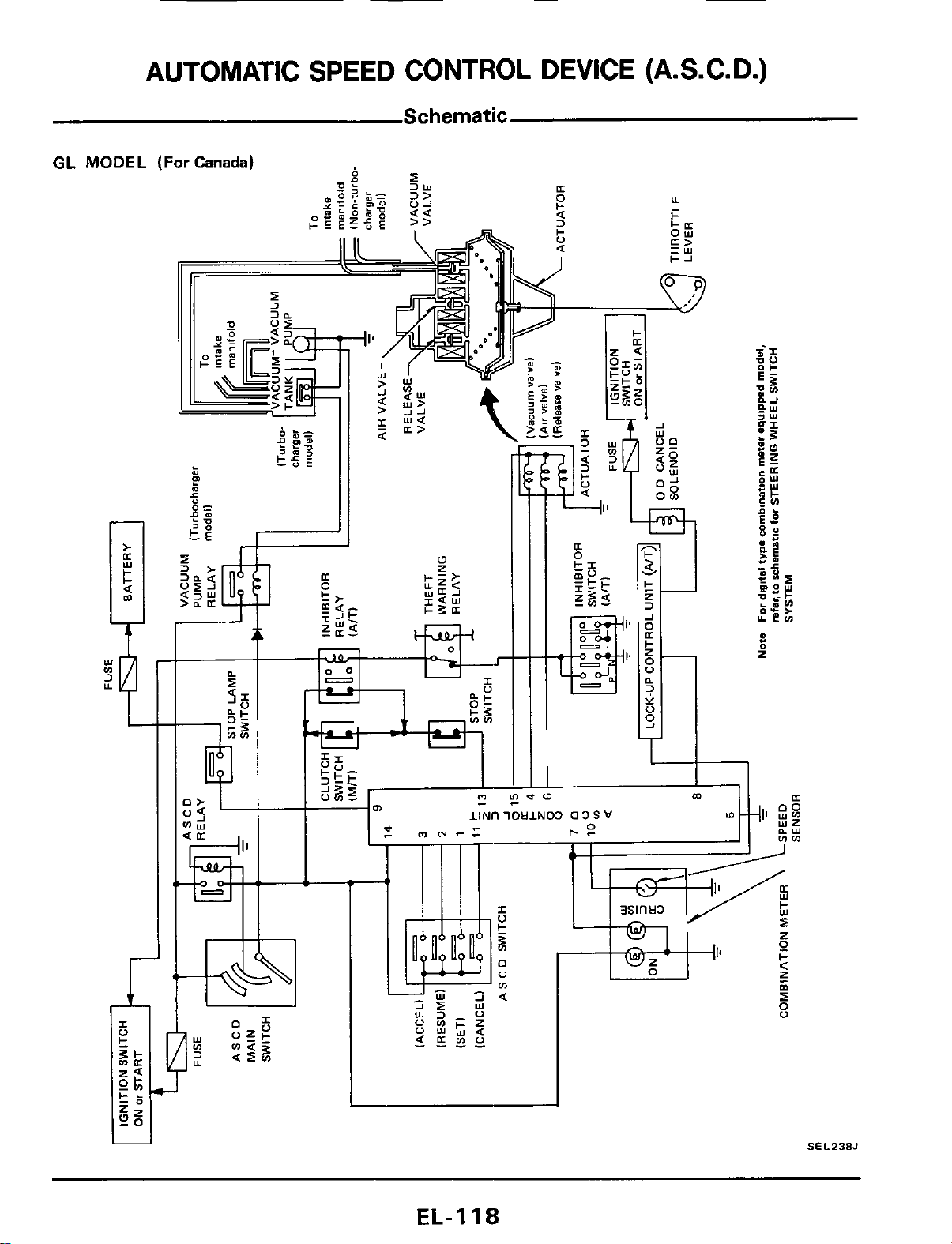
1
SEL238J
EL-I
18
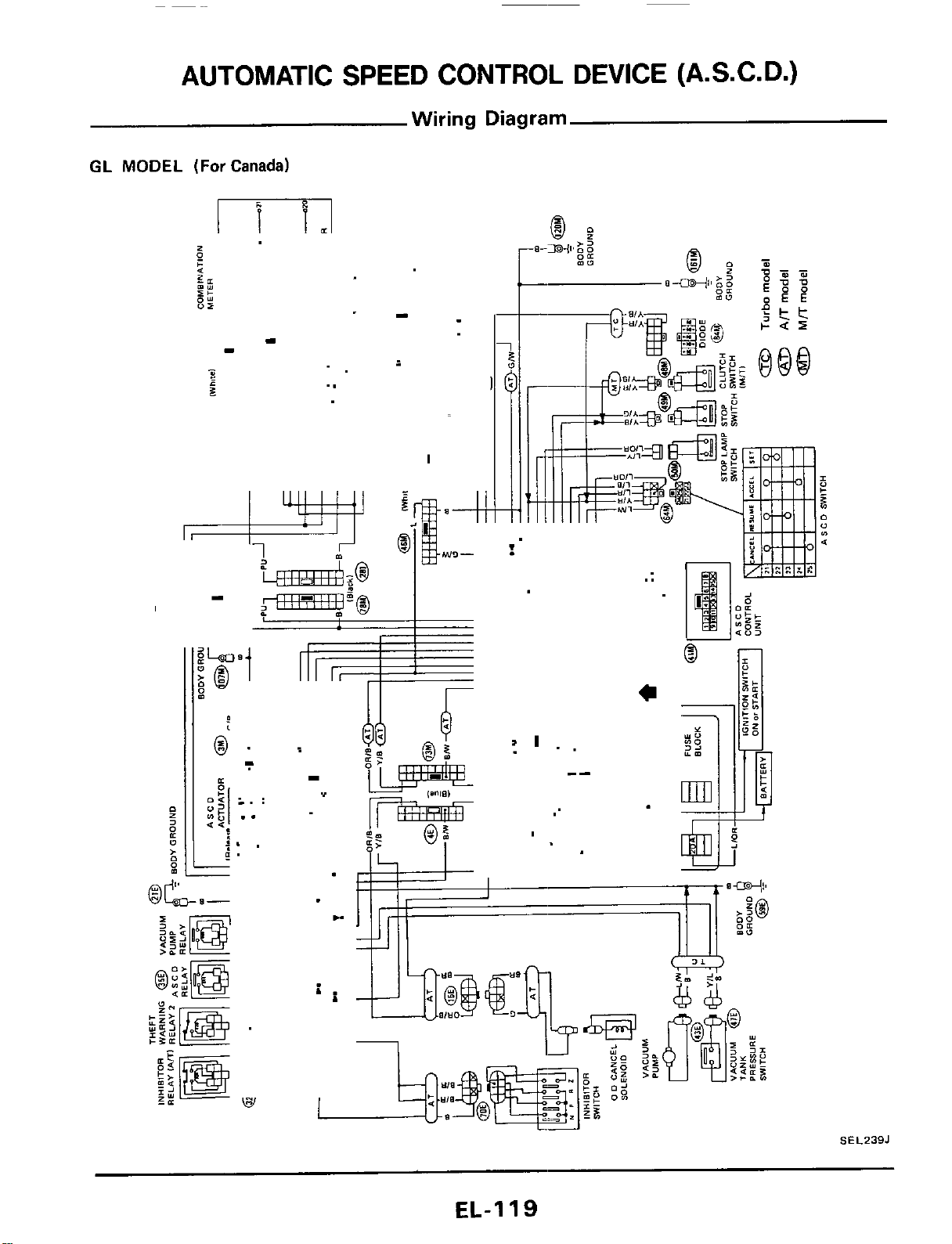
AUTOMATIC SPEED CONTROL DEVICE (A.S.C. D.)
Wiring Diagram
GL
MODEL
(For
Canada)
m
I
-
-
”
..
i
-
I
SEL239J
EL-1
I9
AUTOMATIC SPEED CONTROL DEVICE
Wiring Diagram
GLL
MODEL
Refer
to
wiring diagram for STEERING WHEEL SWITCH
(A.S.C. D.)
(Cont'd)
SYSTEM
EL-I
20
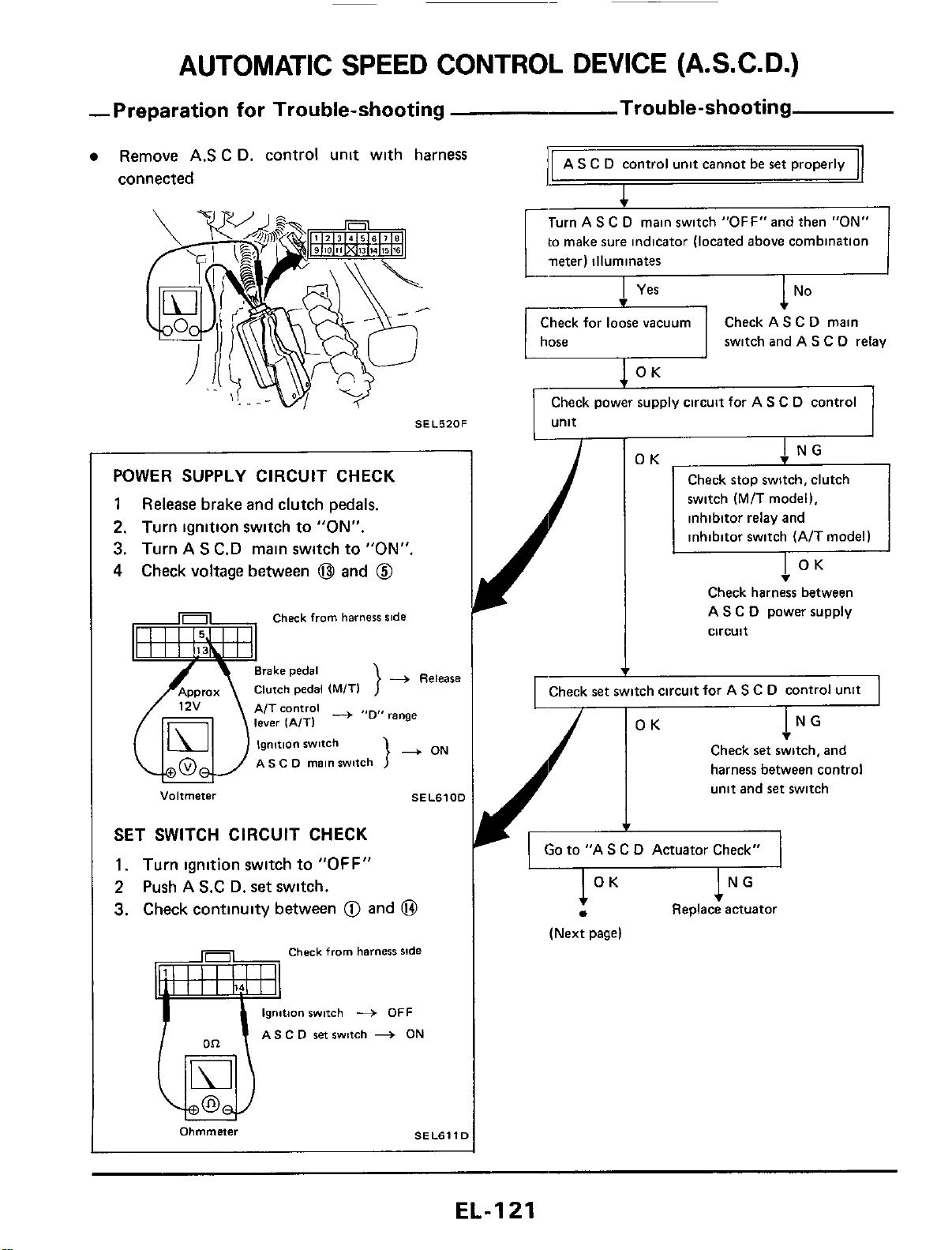
AUTOMATIC SPEED CONTROL DEVICE (A.S.C.D.)
-Preparation for Trouble-shooting Trou ble-shooting
AS
C
D
control unit cannot be ret properly
Remove
AS
C
D. control unit with harness
connected
I
Turn AS
C
D
main switch "0FF"and then
"ON"
to
make sure indicator (located above combination
neter) illuminates
switch and AS
C
D
relay
SEL520F
POWER SUPPLY CIRCUIT CHECK
1
Release
brake and clutch pedals.
2.
Turn ignition switch to
"ON".
3.
Turn
A
S
C.D main switch
to
"ON"
4
Check voltage between
@
and
@
Check
from
harness
ride
-+
Release
}
A/T
control
-
range
}
+
ON
AS
C
D
main
switch
Voltmeter
SEL6100
SET SWITCH CIRCUIT CHECK
1.
Turn ignition switch to
"OFF"
2
Push
A
S.C
D.
set
switch.
3.
Check continuity between
@
and
@
Check
from
harness
ride
gnition
switch
+
OFF
AS
C
D
set
switch
-+
ON
Ohmmner
SELBl
Y
I
Check stop switch, clutch
switch
(M/T
model),
inhibitor relay and
inhibitor switch (A/T model)
v
Check harness between
A
S
C
D
power supply
circuit
I
rCheck
set
switch circuit for A
s
c
D
control unit
I
I
NG
v
OK
Check
set
switch, and
harness between control
unit and ret switch
v
'A
S
C
D
Actuator Check"
1
OK
NG
Replace actuator
(Next page)
EL-I
21
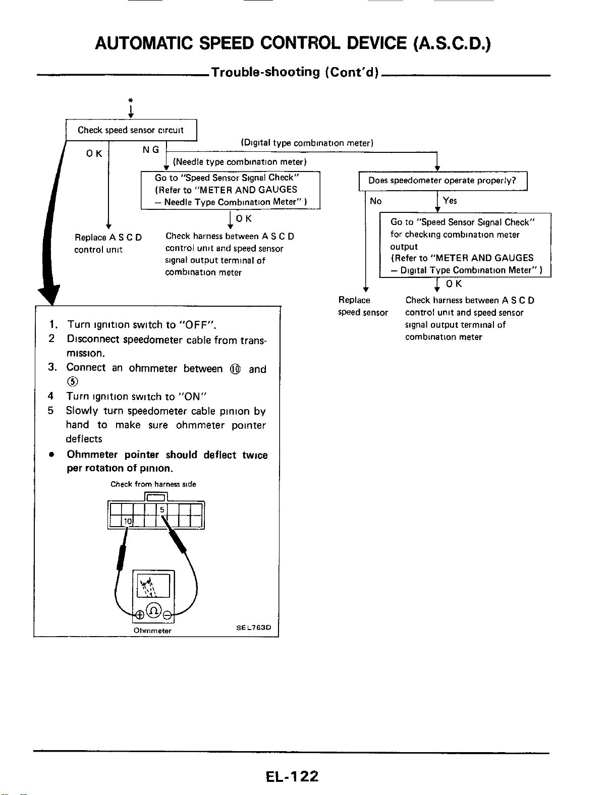
AUTOMATIC
SPEED
CONTROL DEVICE (A.S.C.
D.)
Trouble-shooting (Cont'd)
*
1
Check speed sensor circuit
(Digital type combination meter)
I
Does speedometer operate properly?
I
1
(Refer to "METER AND GAUGES
-
Needle Type Combination Meter"
)
l°K
control unit and speed sensor
signal output terminal
of
combination meter
Check harness between
A
S
C
D
I'
Replace A
S
C
D
control unit
1.
Turn ignition switch to
"OFF".
2
Disconnect speedometer cable from trans-
mission.
3.
Connect an ohmmeter between
@
and
0
4
5
Turn ignition switch to
"ON"
Slowly turn speedometer cable pinion by
hand to make sure ohmmeter pointer
deflects
Ohmmeter pointer should deflect twice
per rotation
of
pinion.
0
Check
from
harness
ride
SEL763D
Ohmmeter
I
Yes
I
No
-
Go
to
"Speed Sensor Signal Check"
for checking combination meter
(Refer to "METER AND GAUGES
-
Digital Type Cornbination Meter"
)
Check harness between AS
C
D
control unit and speed sensor
signal output terminal of
combination meter
Replace
speed sensor
EL-1
22
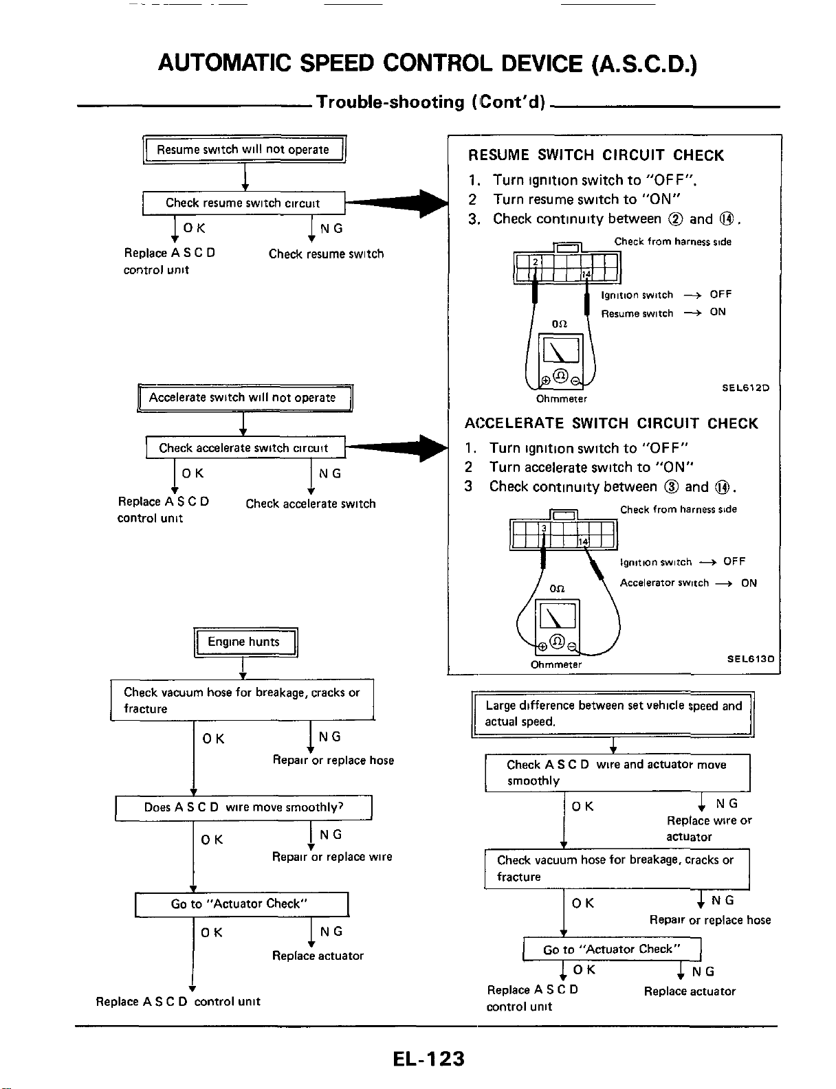
AUTOMATIC SPEED CONTROL DEVICE (A.S.C.
D.)
Trouble-shooting (Cont'd)
-
1
OK
1
NG
OK
4
NG
Replace wire or
actuator
Replace AS C
D
control
unit
Check resume switch
Accelerate switch will not operate
I
v
I
OK
1""
Replace A
S
C
D
control unit
Check accelerate switch
Engine hunts
Q
Check vacuum hose for breakage, cracks or
fracture
OK
lNG
Repair or replace hose
4
Does A
S
C D wire move smoothlv?
1
I
NG
v
OK
Repair or replace wire
I
Go
to "Actuator Check"
OK
lNG
Replace actuator
I
v
Replace AS C
D
control unit
RESUME SWITCH CIRCUIT CHECK
1.
Turn ignition switch to
"OFF".
2
Turn resume switch to
"ON"
3.
Check continuity between
@
and
0.
heck from harness
slde
ionswitch
+
OFF
Resumerwitch
+
ON
SEL612D
ACCELERATE SWITCH CIRCUIT CHECK
1.
Turn ignition switch to
"OFF"
2
Turn accelerate switch to
"ON"
3 Check continuity between
@I
and
0.
Check from harness
side
ignition switch
+
OFF
Accelerator swmh
+
ON
SEL613C
Ohmmeter
Check vacuum hose for breakage, cracks or
fracture
4
NG
I
OK
Repair or replace hose
1
Go
to "Actuator Check"
I
c
NG
Replace actuator
1
OK
Replace A
S
C
D
control unit
EL-I
23
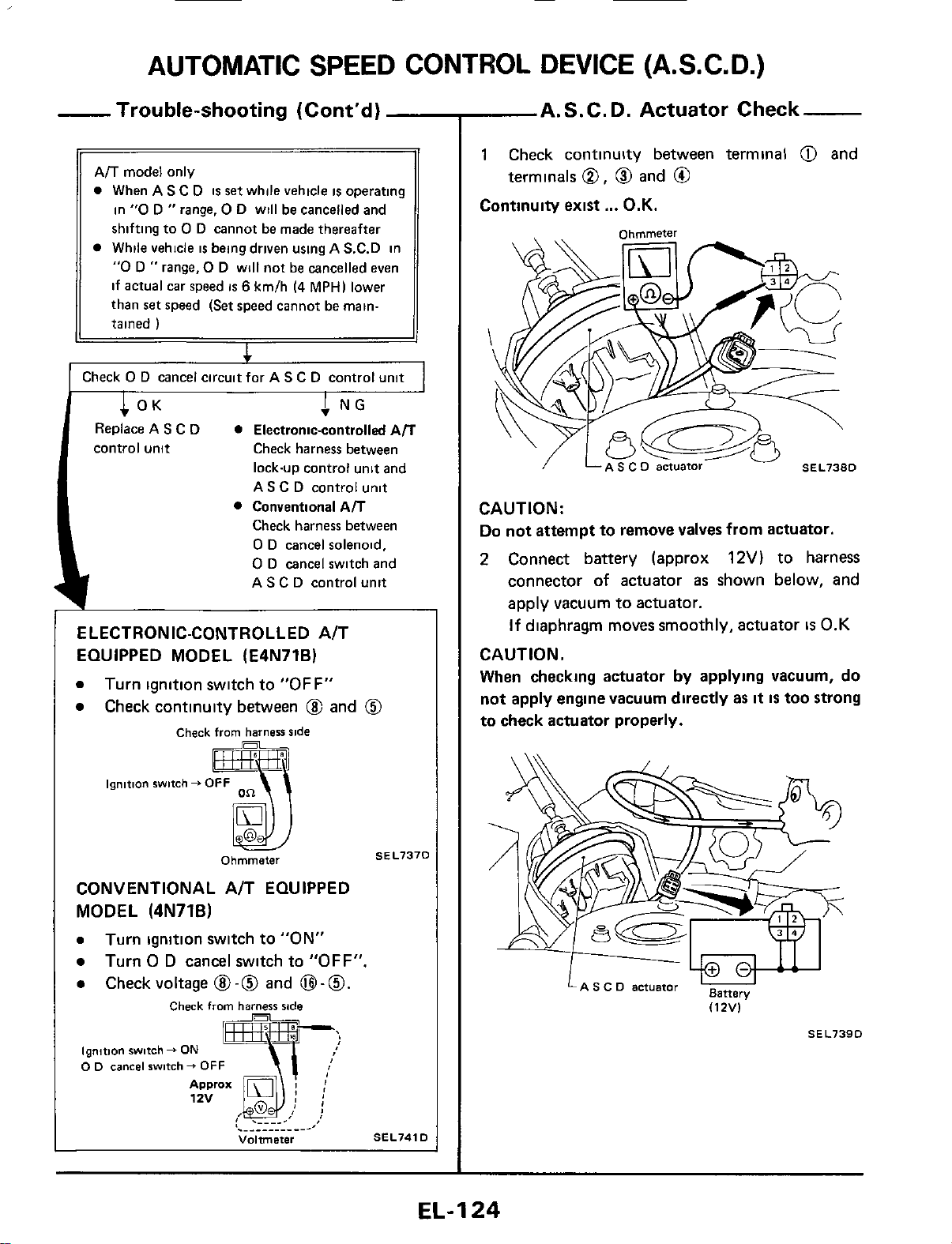
AUTOMATIC
SPEED
CONTROL DEVICE (A.S.C. D.)
~
ELECTRONIC-CONTROLLED A/T
EQUIPPED MODEL (E4N71B)
0
Turn ignition switch to
"OFF"
Check continuity between
@
and
@
-
Trouble-shooting (Cont'd)
Ail
model only
0
When
AS
C
D
is
set
while vehicle
is
operating
in
"0
D
"
range,
0
D will be cancelled and
shifting to
0
D cannot be made thereafter
While vehicle
is
being driven using
A
S.C.D in
"0
D
"
range,
0
D will not be cancelled even
if actual car speed
is
6
km/h
14
MPH)
lower
than
set
speed
(Set
speed cannot be main-
tained
)
I
I
Check
0
D
cancel circuitfor
AS
C
D control unit
I
CONVENTIONAL A/T EQUIPPED
MODEL
(4N71B)
0
Turn ignition switch to "ON"
0
Turn
0
D
cancel switch to
"OFF".
0
Checkvoltage
@-@
and
B-0.
I
Check
from
harzsr
side
ignition
switch
f
ON
0
0
cancel
switch
+
OFF
Volrmeter
SEL741D
A.S.C.D. Actuator Check
1
Check continuity between terminal
@I
and
Continuity exist
...
O.K.
terminals
0,
0
and
@
Ohmmeter
\
CAUTION:
Do
not attempt to remove valves from actuator.
2
Connect battery (approx
12V)
to
harness
connector
of
actuator
as
shown below, and
apply vacuum
to
actuator.
If
diaphragm moves smoothly, actuator
is
0.K
CAUTION.
When
checking actuator
by
applying vacuum, do
not apply engine vacuum directly as
it
IS
too strong
to check actuator properly.
LA
s
c
D
actuator
BBttery
(12V)
SEL739D
EL-I
24
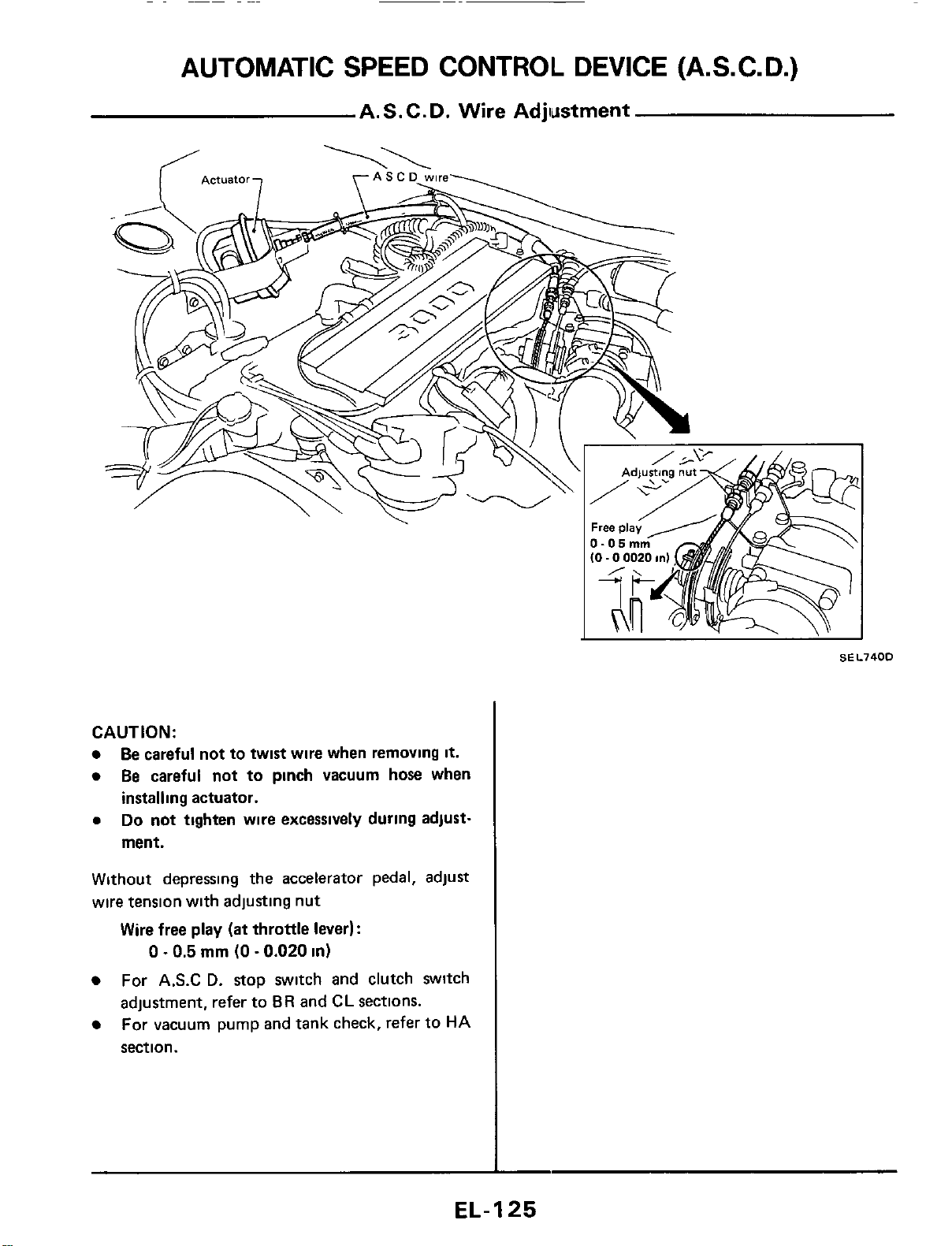
CAUTION:
Be careful not to twist wire when removing
it.
Be careful not to pinch vacuum hose when
installing actuator.
0
Do
not
tighten wire excessively during adjust-
ment.
Without depressing the accelerator pedal, adjust
wire tension with adjusting nut
Wire free play
(at
throttle lever):
0
-
0.5
mm
(0
-
0.020
in)
For
A.S.C
D.
stop switch and clutch switch
adjustment, refer to
BR
and
CL
sections.
For vacuum pump and tank check, refer to
HA
section.
EL-I
25
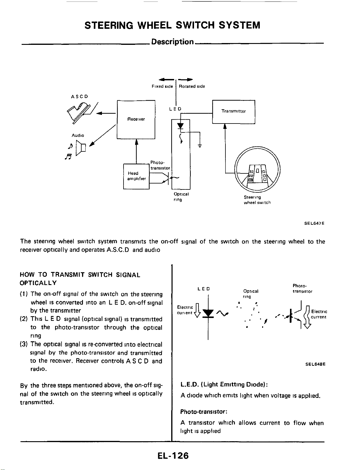
STEERING WHEEL SWITCH SYSTEM
Description
b-
Fixed
side
Rotated ride
I
Transmitter
ASCO
Receiver
Audio
Phata-
A
Optical
ring
steerjng
wheel
switch
SE L647 E
The steering wheel switch system transmits the on-off signal of the switch on the steering wheel to the
receiver optically and operates A.S.C.D and audio
HOW TO TRANSMIT SWITCH SIGNAL
OPTICALLY
(1
I
The on-off signal of the switch on the steering
wheel
is
converted into an
L
E
D. on-off signal
by the transmitter
(2)
This
L
E
D
signal (optical signal)
is
transmitted
to the photo-transistor through the optical
ring
(3) The optical signal
is
reconverted into electrical
signal
by the photo-transistor and transmitted
to the receiver. Receiver controls A
S
C
D and
radio.
By
the three steps mentioned above, the on-off
sig-
nal
of
the
switch on
the
steering wheel
is
optically
transmitted.
Optical
LED
ring
Photo-
transstor
SEL648E
L.E.D.
(Light
Emitting Diode):
A diode which emits light when voltage
is
applied.
Photo-transistor:
A transistor which allows current to flow when
light
is
applied
EL-1
26
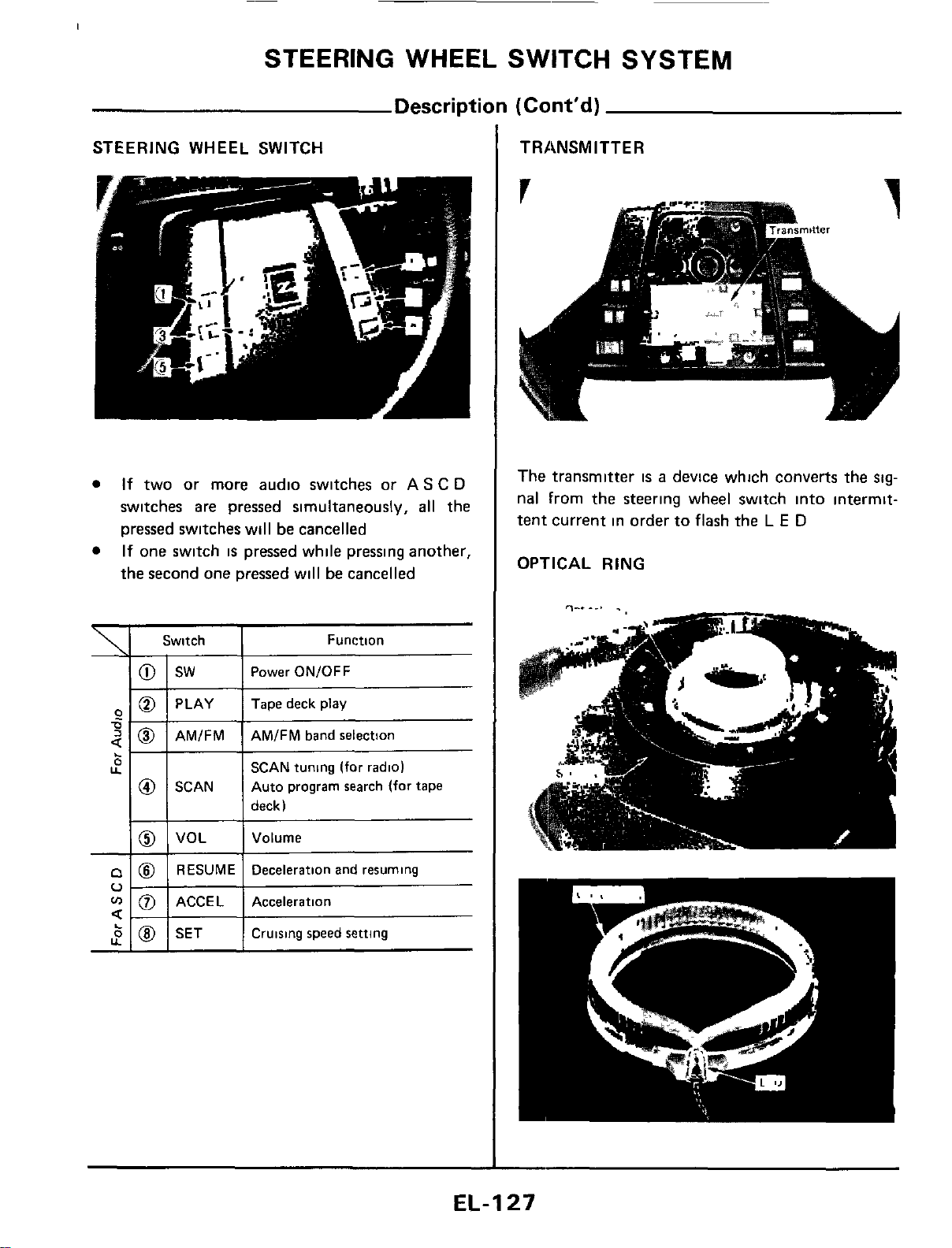
STEERING WHEEL SWITCH SYSTEM
Description
(Cont'd)
STEERING WHEEL SWITCH
If
two or more audio switches
or
AS
C
D
switches are pressed simultaneously,
all
the
pressed switches will
be
cancelled
If one switch
is
pressed while pressing another,
the second one pressed will
be
cancelled
\
1
Switch
6
U
'i
0
sw
PLAY
AMIFM
SCAN
VOL
RESUME
ACCE L
SET
Function
Power ON/OFF
Tape deck play
AMIFM band selection
SCAN tuning
(for
radio)
Auto program search (for tape
deck)
Volume
Deceleration and resuming
Acceleration
Cruising speed
setting
TRANSMITTER
The transmitter
is
a
device which converts the
sig-
nal From the steering wheel switch into intermit-
tent current in order to flash the
L
E
D
OPTICAL RING
EL-I
27
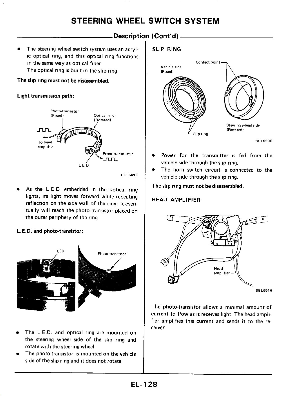
STEERING WHEEL SWITCH SYSTEM
Description
(Cont’d)
The steering wheel switch system
uses
an acryl-
ic optical ring, and this optical ring functions
in the same way
as
optical fiber
The optical ring
is
built in the slip ring
The
slip
ring must not be disassembled.
Light transmission path:
Photo-transistor
(Fixed)
Optical
rlng
I
1
Rotated
l
amplifier
From
transmitter
LE^
SEL649E
As
the
L
E
D
embedded in the optical ring
lights,
its
light moves forward while repeating
reflection on the side wall of the ring
It
even-
tually will reach the photo-transistor placed on
the outer periphery
of
the ring
L.E.D.
and photo-transistor:
Photo-transistor
LED
a
,
The
L
E.D.
and optical ring
are
mounted on
the steering wheel side of the slip ring and
rotate with the steering wheel
The photo-transistor
is
mounted on the vehicle
side
of the slip ring and
it
does not rotate
SLIP
RING
contact
Dolnt
-
I\
Vehicle
side
Steering
vvheel
%de
(Rotatedl
SllP
rlng
SEL650E
Power for the transmitter
is
fed from the
vehicle side through the slip ring.
The horn switch circuit
is
connected to
the
vehicle side through the slip ring.
The
slip ring must not be disassembled.
HEAD AMPLIFIER
SEL651
E
The photo-transistor allows
a
minimal amount of
current to flow
as
it
receives light The head ampli-
fier
amplifies this current and sends
it
to the re-
ceiver
EL-I
2%
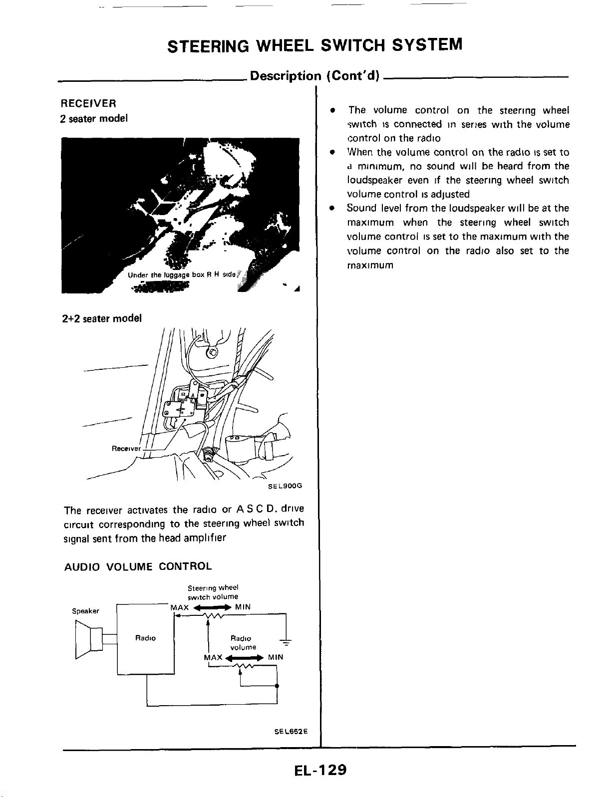
_-
STEERING
WHEEL
SWITCH
SYSTEM
Description
(Cont'd)
RECEIVER
2
seater
model
2+2
seater
model
SEL900G
The receiver activates the radio or
AS
C
D.
drive
circuit corresponding to the steering
wheel
switch
signal sent from the head amplifier
AUDIO VOLUME
CONTROL
"..
..
MAX
U
MIN
Speaker
Radio
Radio
volume
MAX
MIN
SEL657.E
The volume control on the steering wheel
switch
is
connected in series with the volume
tcontrol
on
the radio
"hen the volume control on the radio
is
set
to
<I
minimum, no sound will
be
heard from the
loudspeaker even
if
the steering wheel switch
volume
control
is
adjusted
Sound
level
from the loudspeaker will
be
at
the
rnaximum when the steering wheel switch
volume control
is
set
to the maximum with the
volume
control
on
the radio also
set
to the
rnaximum
EL-129
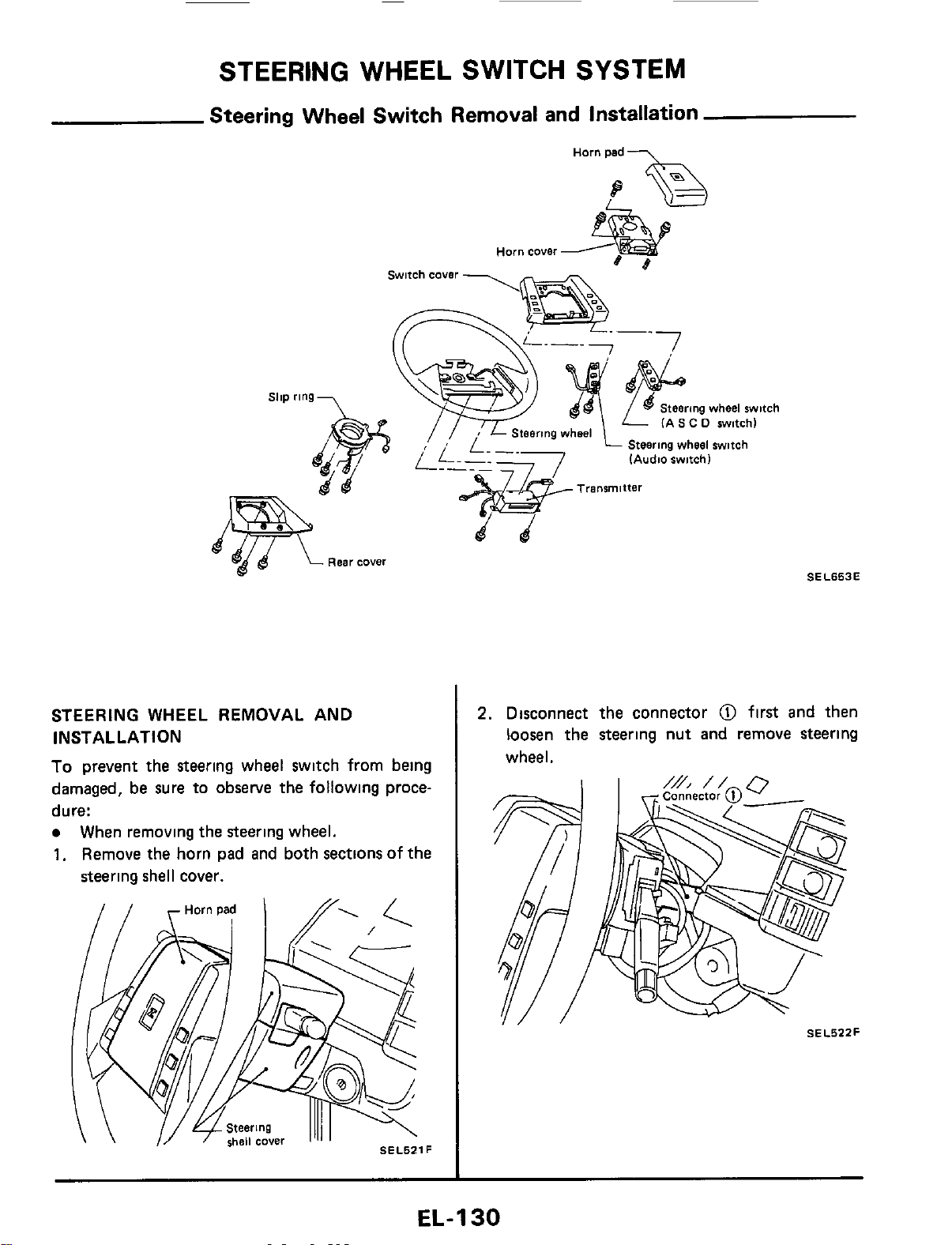
STEERING WHEEL SWITCH SYSTEM
Steering Wheel Switch Removal and Installation
\
STEERING WHEEL REMOVAL AND
INSTALLATION
To
prevent the steering wheel switch from being
damaged, be sure to
observe
the following proce-
dure:
When removing the steering wheel.
1.
Remove the horn pad and both sections of the
steering shell cover.
Steering
wheel
witch
(AS
C
0
switch)
p-
-
Steering
wheel
switch
(Audio
switch1
Transmitter
SEL653E
2.
Disconnect the connector
@
first and then
loosen the steering nut and remove steering
wheel.
SEL522F
EL-1
30
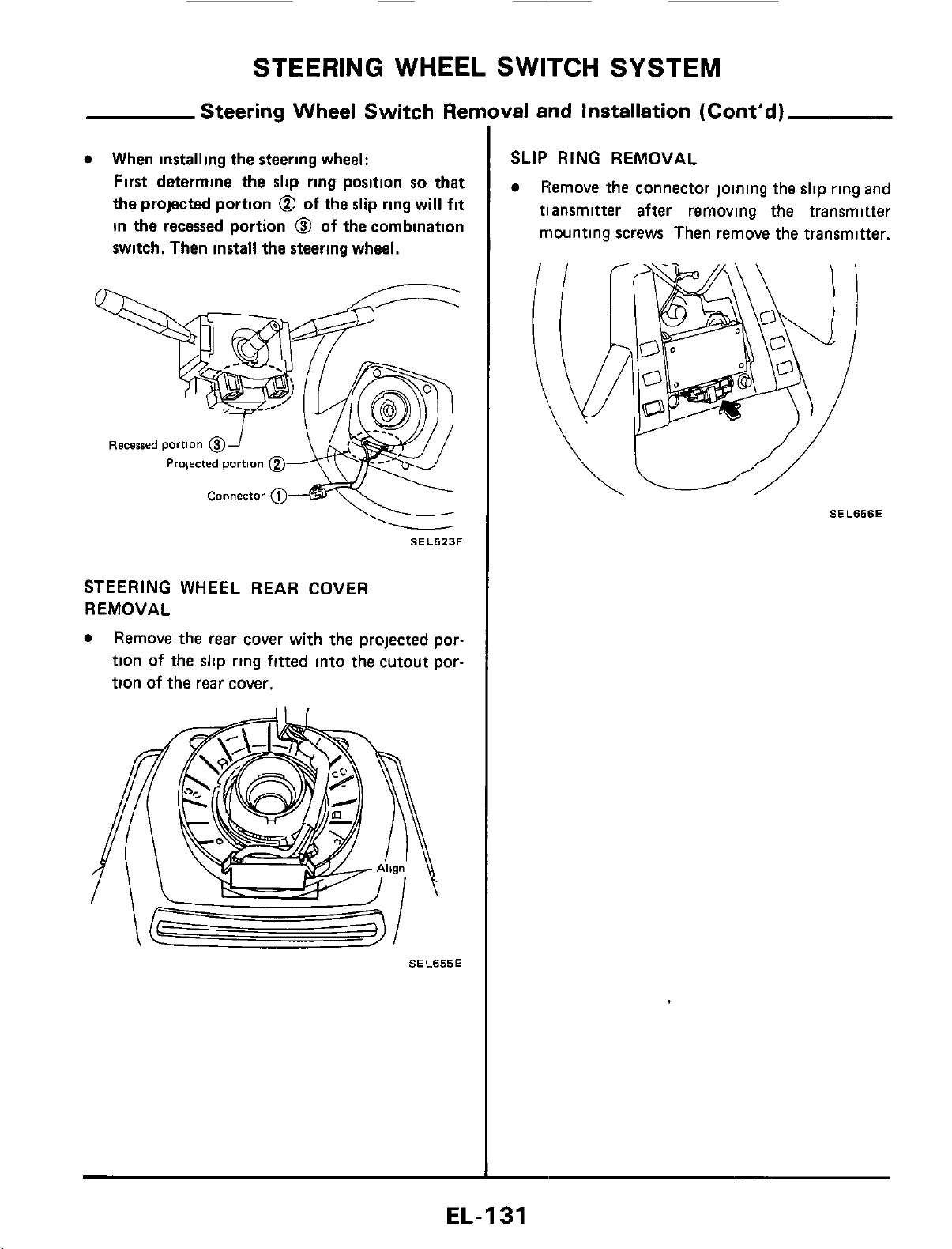
STEERING
WHEEL
SWITCH
SYSTEM
Steering Wheel Switch Ren
When
installing
the steering wheel:
First determine the
slip
ring position
so
that
the projected portion
@
of
the
slip
ring will
fit
in
the
recessed portion
@
of
the
combination
switch. Then install the steering wheel.
Recessed
portion
@
Prqected
portion
@
Connector
04
SEL523F
STEERING
WHEEL REAR COVER
REMOVAL
Remove the
rear
cover with the projected por-
tion of the slip ring fitted into the cutout por-
tion of the
rear
cover.
SEL655E
val and Installation (Cont'd)
SLIP
RING
REMOVAL
Remove the connector joining the slip
ring
and
tiansmitter after removing the transmitter
mounting screws Then remove the transmitter.
SEL656E
EL-I
31
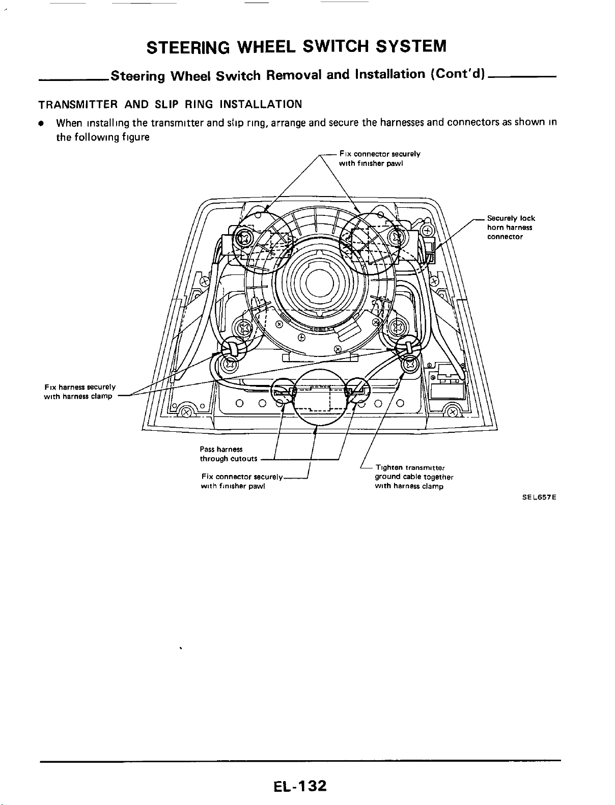
STEERING WHEEL SWITCH SYSTEM
Steering Wheel Switch Removal and Installation (Cont'd)
TRANSMITTER AND
SLIP
RING INSTALLATION
When
installing
the
transmitter
and
slip
ring,
arrange
and
secure
the
harnesses
and
connectors
as
shown
in
the
following figure
FIX
connector securely
with finisher pawl
FIX
harness securely
wnh harness clamp
Tighten
transmitter
ground cable together
with harness clamp
Pass
harness
through cutouts
FIX connector securely
with finisher pawl
SEL657E
EL-I
32
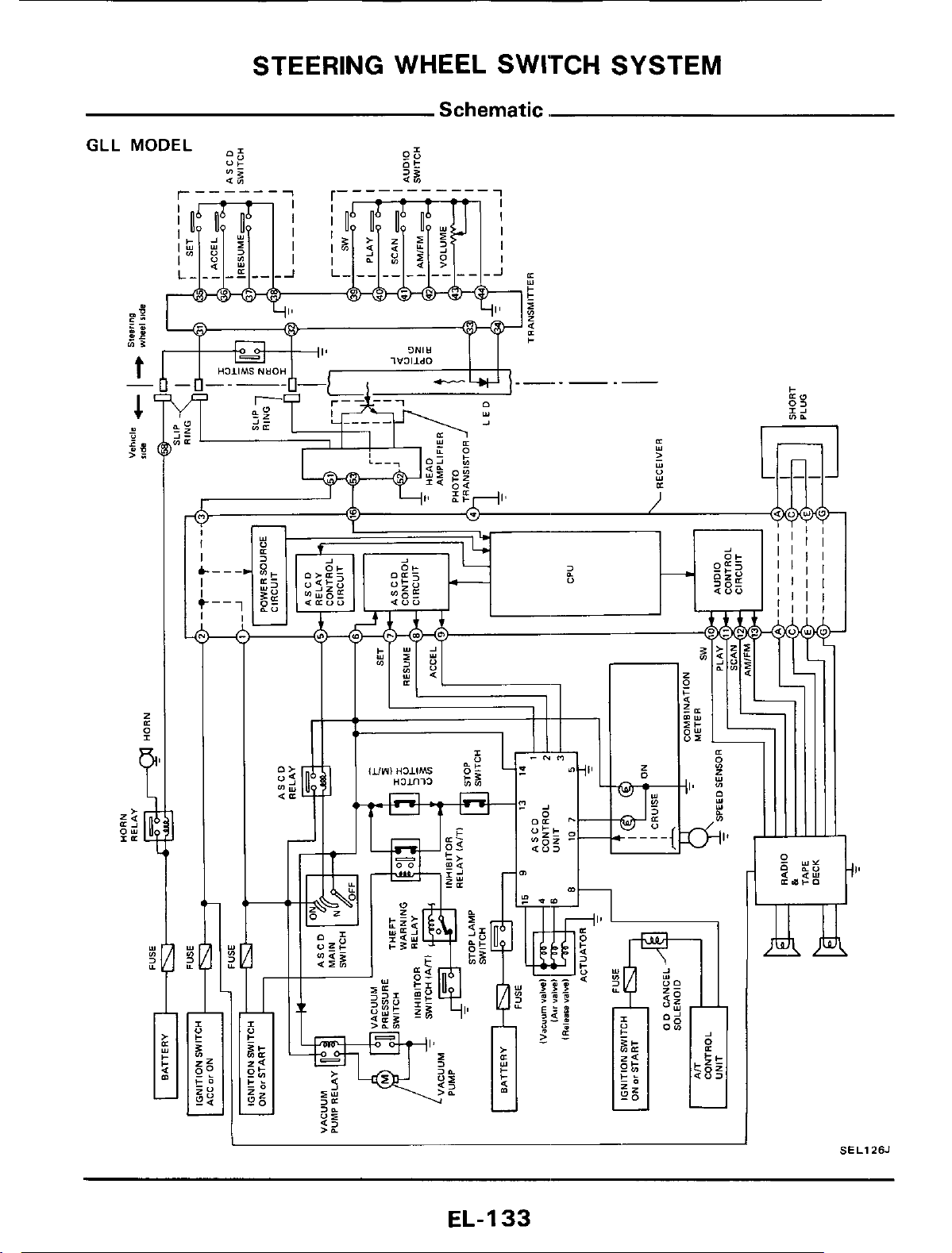
STEERING WHEEL SWITCH SYSTEM
Schematic.
GLL
I
SELlZSJ
EL-I
33
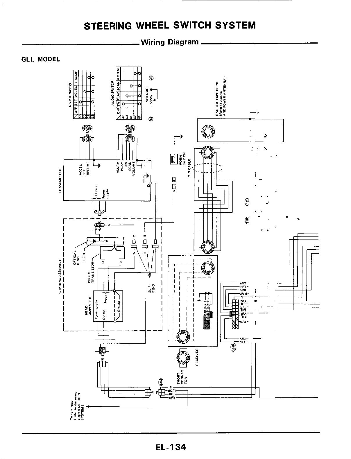
STEERING WHEEL SWITCH SYSTEM
Wiring
Diagram
GLL
MODEL
.
E
.
,
1
4
EL-I
34
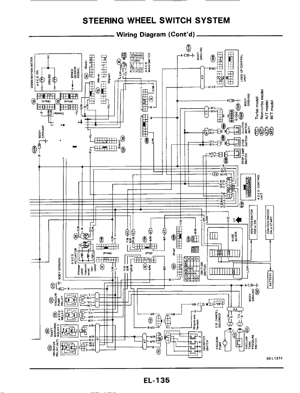
STEERING
WHEEL
SWITCH SYSTEM
Wiring Diagram (Cont'd)
;5
EL-I
35
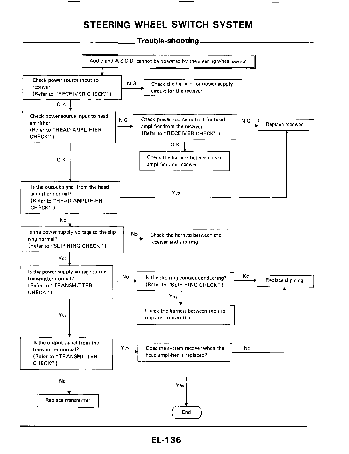
STEERING WHEEL SWITCH SYSTEM
b
Check power source input to head
amplifier
(Refer to "HEAD AMPLIFIER
Trouble-shooting
Audio and AS
C
D cannot be operated by the steering wheel switch
~-
Check power source output for head
amplifier from the receiver
(Refer to "RECEIVER CHECK"
)
4
Replace receiver
Check the harness for power supply
circuit for the receiver
Check power source input to
rece
i
ve
r
(Refer to "RECEIVER CHECK"
)
CHECK"
)
OK
t
Is
the output signal from the head
amplifier normal?
(Refer to "HEAD AMPLIFIER
CHECK"
)
OK
1
I
Yes
OK
Check the harness between head
amplifier and ieceiver
No
1s
the power supply
Check the harness bet ween the
ring normal?
(Refer to "SLIP RING CHECK"
1
receiver and slip ring
Replace slip ring
Is
the slip ring contact conducting?
(Refer to "SLIP
RING
CHECK"
)
Is
the power supply voltage to the
transmitter normal?
(Refer to "TRANSMITTER
CHECK"
)
No+
Yes
Check the harness between the slip
ring and transmitter
Is
the output signal from the
transmitter normal)
(Refer to "TRANSMITTER
head amplifier
is
replaced?
No
I
EfzIl
Replace transmitter
Yes
EL-I
36
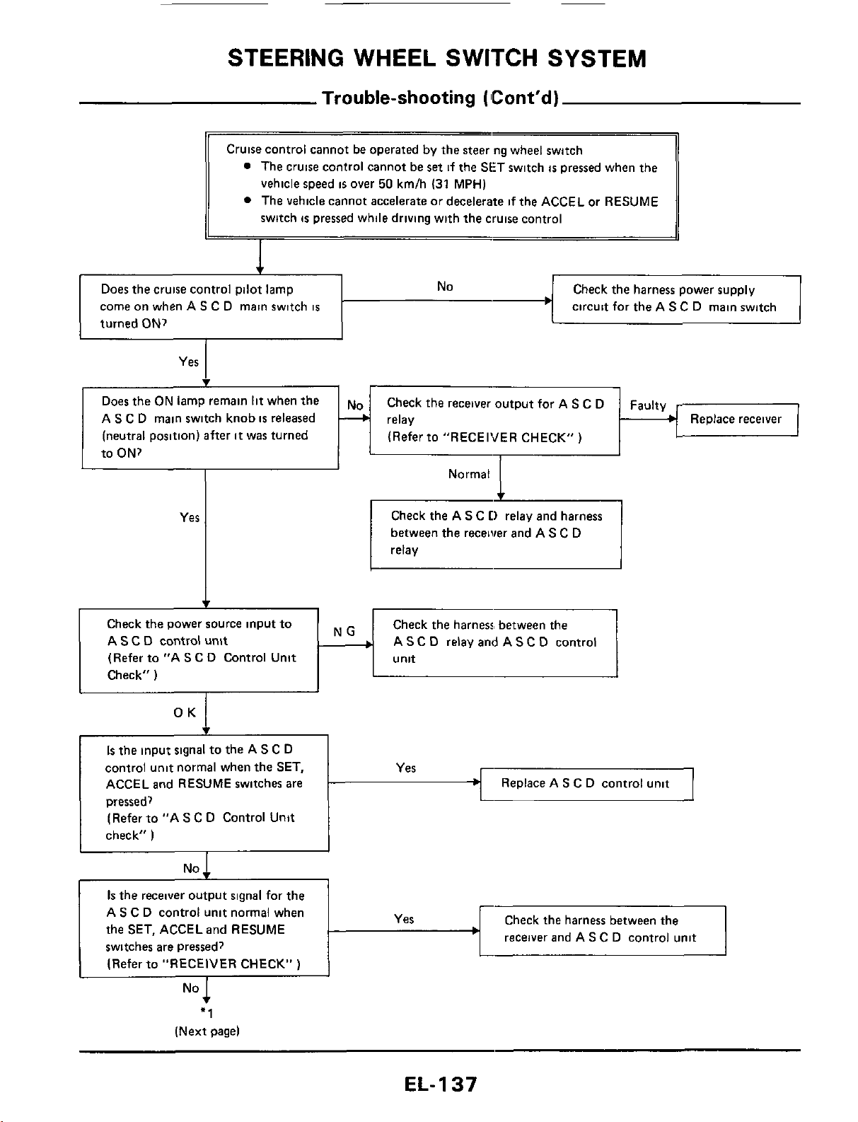
STEERING
WHEEL
SWITCH
SYSTEM
Trouble-shooting
(
ICont'd)
Does the cruise control pilot lamp
come on when AS C D main switch
is
turned
ON?
No
Check the harness power supply
circuit for the A
S
C D main switch
Yes
Does
the
ON
lamp remain
lit
when
the
A
S
C
D main switch knob
is
released
(neutral position) after
it
was turned
to ON?
c
Check the receiver output for A
S
C D
(Refer to "RECEIVER CHECK")
Faulty
3
relay Replace receiver
Check the A
S
C
D
relay and harness
between the receiver and AS C D
relay
Check
the
power source input to
A
S
C
D
control
unit
(Refer to "A
S
C D Control Unit
Check"
)
Check the harness, between the
A
S
C D relay and A
S
C D control
Is
the
input signal to the AS
C
D
control unit normal when the
SET,
ACCEL and RESUME switches are
pressed,
(Refer to "A
S
C
D Control Unit
check"
)
Replace AS C D control unit
No
I
I
receiver
and A
S
C D control unit
Is
the
receiver output signal for the
AS C D control unit normal when
the SET, ACCELand RESUME
switches are pressed?
(Refer to "RECEIVER CHECK"
)
"1
(Next
pagel
EL-
1
37
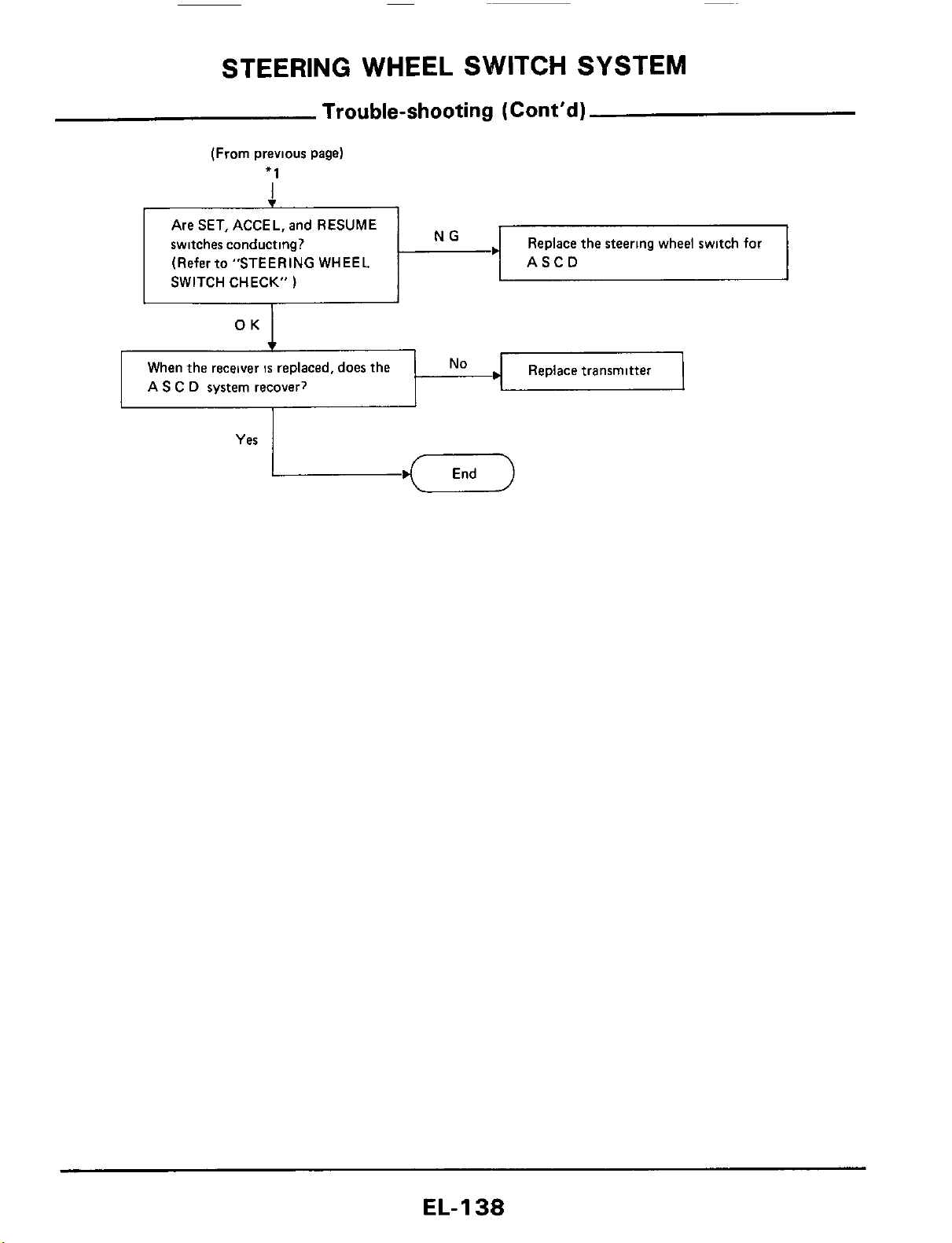
STEERING WHEEL SWITCH SYSTEM
Trouble-shooting
(Cont’d)
(From previous page)
+1
Are SET, ACCEL, and RESUME
switches conducting?
Replace the steering wheel switch
for
71
SWITCH (Refer to CHECK” ”STEERING
)
WHEEL NG
.I
ASCD
Fy
When the receiver
IS
replaced, does the
No
A
S
C
D
system recover?
Yes
EL-I
38
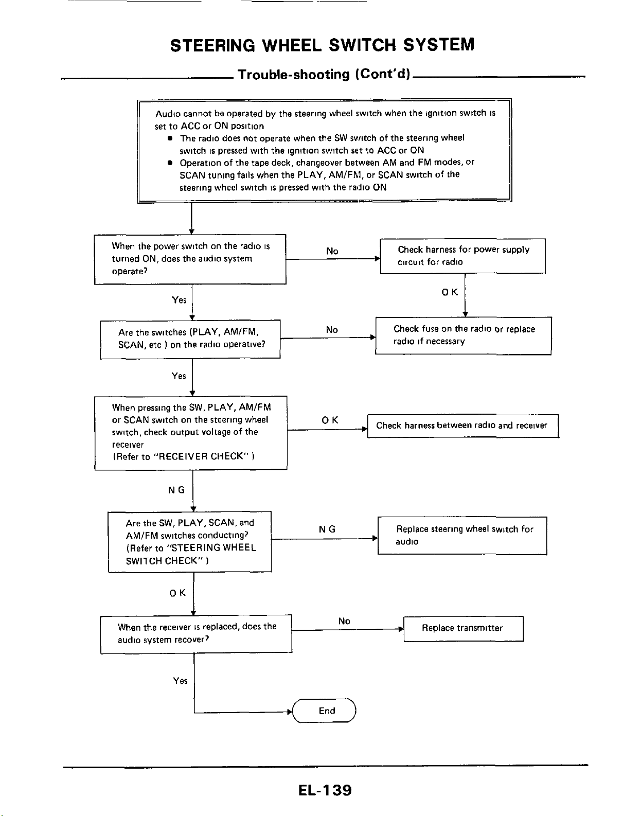
STEERING
WHEEL
SWllTCH
SYSTEM
Trouble-shooting
(Cont'd)
1
Audio cannot
be
operated by the steering wheel switch when
the
ignition swttch
IS
set
to ACC or ON position
a
The radio does not operate when the SW switch of the steering wheel
switch
is
pressed with
the
ignition switch
set
to ACC or ON
a
Operation of the tape deck, changeover between AM and FM modes. or
SCAN tuning
fails
when the PLAY, AMlFhl, or SCAN switch
of
the
steering wheel switch
is
pressed with the radio ON
Yes
When
the
receiver
IS
replaced, does
the
audio system recover?
1
c
No
Replace transmitter
Check fuse on
the
radio or replace
radio if necessary
Are
the
switches (PLAY. AMIFM,
I
SCAN,
etc
)
on the radio operative?
Check harness between radio
and
receiver
When pressing the SW. PLAY, AMIFM
or
SCAN switch on the steering wheel
switch, check output voltage of the
receiver
(Refer to "RECEIVER CHECK"
)
I
I
~~
Replace steering wheel switch for
Are the SW. PLAY, SCAN, and
AMIFM switches conducting?
(Refer to "STEERING WHEEL
SWITCH CHECK"
)
EL-139
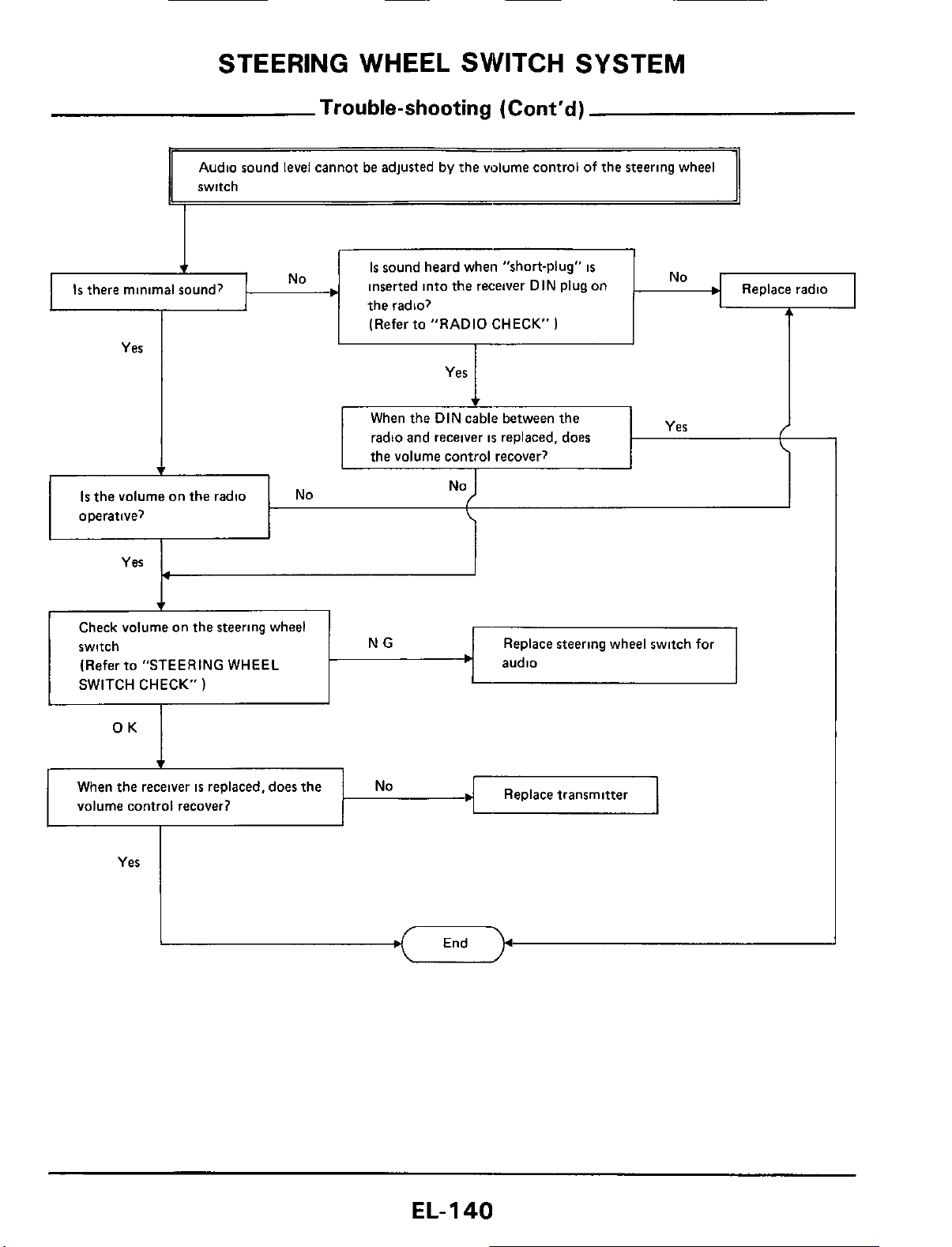
STEERING WHEEL SWITCH SYSTEM
Trouble-shooting
(Cont'd)
Is
the volume on the radio
operative?
Audio sound level cannot be adjusted by the volume control of the steering wheel
switch
NO
No
I
4
When
the
receiver
is
replaced, does
the
volume control recover?
r
Is
sound heard when "short-plug"
is
inserted into the receiver DIN Plug on
the radio?
Replace transmitter
No
Yes
I
(Refer to "RADIO CHECK"
)
I
Yes
I
Replace steering wheel switch for
audio
Check volume on the steering wheel
switch
(Refer to "STEERING WHEEL
SWITCH CHECK"
)
Yes
EL-I
40
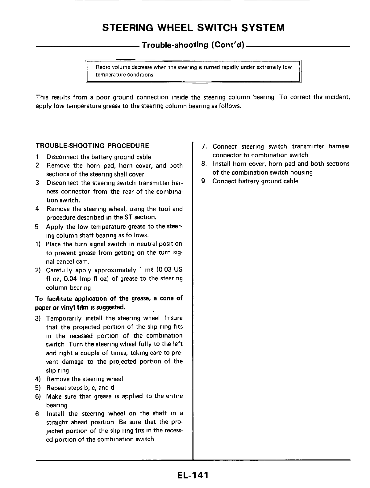
STEERING WHEEL SWITCH SYSTEM
Trouble-shooting
(Cont’d)
Radio
volume
decrease
when
the
Steering
is
temperature
conditions
This results from
a
poor ground connection inside the steering column bearing
To
correct the incident,
apply low temperature
grease
to the steering column bearing
as
follows.
TROUBLE-SHOOTING PROCEDURE
1
2
3
Disconnect the battery ground cable
Remove the horn pad, horn cover, and both
sections of the steering shell cover
Disconnect the steering switch transmitter har-
ness connector from the rear of the combina-
tion switch.
4
Remove the steering wheel, using the tool and
procedure described in the ST section.
5
Apply the low temperature grease to the steer-
ing column shaft bearing
as
follows.
1)
Place the turn signal switch in neutral position
to prevent
grease
from getting on the turn
slg-
nal cancel cam.
2)
Carefully apply approximately
1
mP
(0
03
US
fl
02,
0.04
Imp
fl
02)
of grease to the steering
column bearing
To
facilitate application of the grease, a cone of
paper or vinyl film
is
suggested.
3) Temporarily install the steering wheel Insure
that the projected portion of the slip ring
fits
in the recessed portion of the combination
switch Turn the steering wheel fully to the
left
and right
a
couple of times, taking care to pre-
vent damage to the projected portion of the
slip ring
4)
Remove the steering wheel
5)
Repeat steps b, c, and d
6)
Make sure that
grease
is
applted to the entire
bearing
6
Install the steering wheel on the shaft in
a
straight ahead position
Be
sure that the pro-
jected portion of the slip ring
fits
in the recess-
ed portion of the combination switch
7.
Connect steering switch transmitter harness
connector to combination switch
8.
Install horn cover, horn pad and both sections
of the combination switch housing
9
Connect battery ground cable
EL-I
41
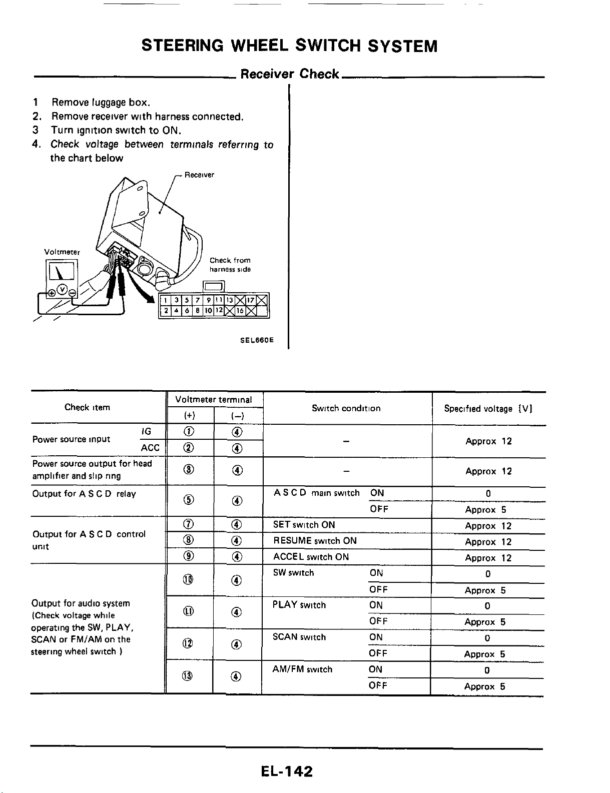
STEERING WHEEL SWITCH SYSTEM
Receiver
Check
1
Remove
luggage
box.
2.
Remove
receiver
with
harness
connected.
3
Turn
ignition
switch
to
ON.
4.
Check
voltage
between
terminals
referring
to
the
chart
below
OFF
Check item
Approx
5
IG
ACC
-
Power source input
Power source output for head
amplifier and slip ring
Output for A
S
C
D
relay
OFF
Output for AS
C
D
control
unit
~
Approx
5
Output
for
audio system
(Check voltage while
operating the
SW.
PLAY,
SCAN or FMIAM on the
steering wheel switch
)
OFF
AMIFM switch ON
OFF
SEL66OE
-
Approx
5
0
Approx
5
Voltmeter terminal
0
0
0
0
0
0
-
-
Switch condition Specified voltage [VI
Approx
12
I
Approx
12
I
AS
C
D
main switch ON
I
0
OFF
I
ADDrox
5
ACCEL switch ON
I
EL-
1
42
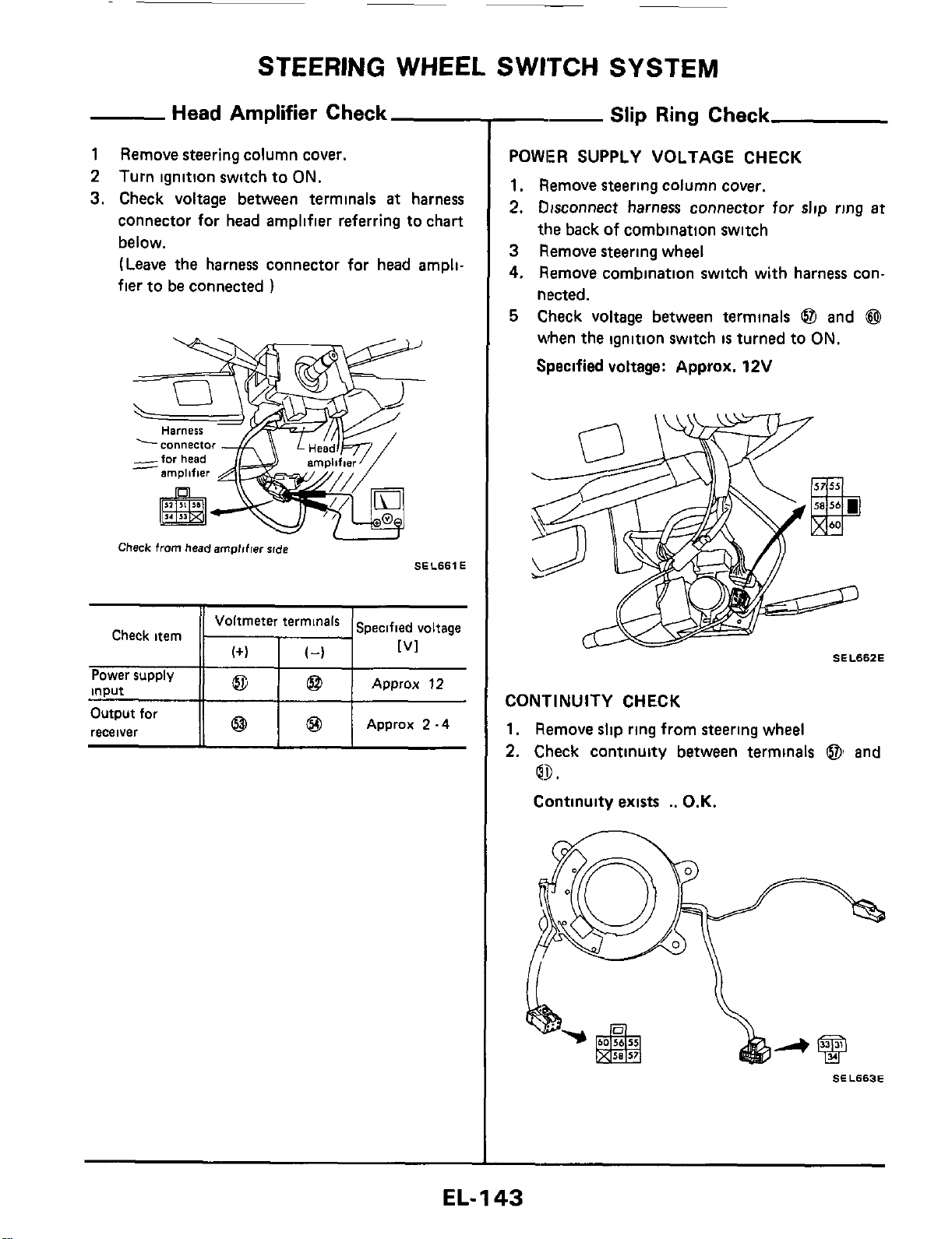
~
STEERING WHEEL SWITCH SYSTEM
Head
Amplifier Check
1
Remove steering column cover.
2
Turn ignition switch to
ON.
3.
Check voltage between terminals
at
harness
connector for head amplifier referring to chart
below.
(Leave
the harness connector for head ampli-
fier to be connected
)
Harness
-Y7
Check
from
headempltfw
rlde
SEL661 E
Check item
I
I
Approx
12
Power supply
input
--
Slip
Ring
Check
POWER SUPPLY VOLTAGE CHECK
1.
Remove steering column cover.
2.
Disconnect harness connector for
slip
ring
at
the back
of
combination switch
3
Remove steering wheel
4.
Remove combination switch with harness con-
nected.
5
Check voltage between terminals
@I
and
@
when the ignition switch
is
turned to
ON.
Specified voltage: Approx. 12V
SEL662E
CONTINUITY CHECK
1.
Remove slip ring from steering wheel
2.
Check continuity between terminals
@I
and
Q9.
Continuity exists
..
O.K.
SEL663E
EL-I
43
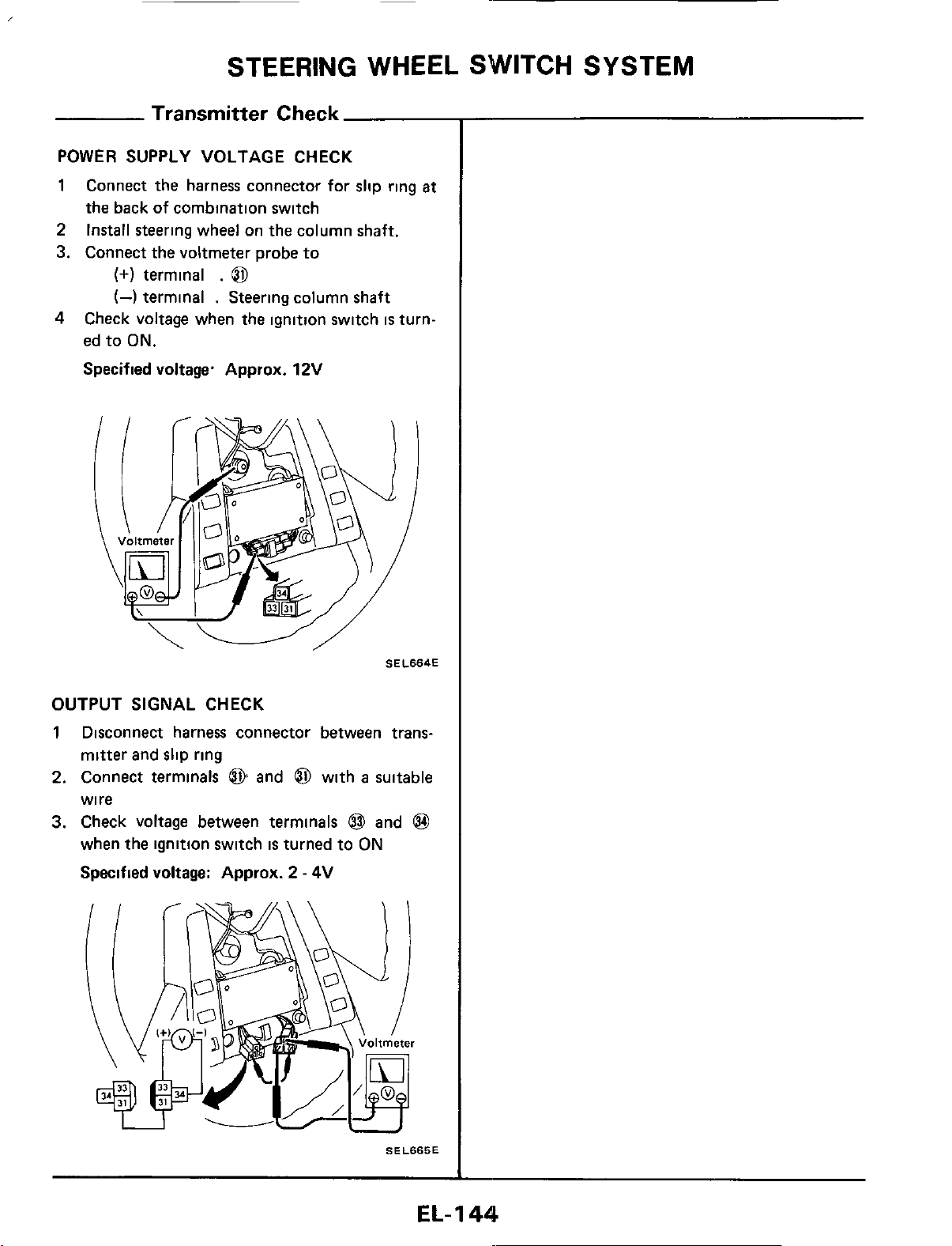
STEERING WHEEL SWITCH SYSTEM
Transmitter
Check
POWER SUPPLY VOLTAGE CHECK
1
Connect the harness connector for slip ring
at
the back of combination switch
2
Install steering wheel on the column shaft.
3. Connect the voltmeter probe to
(+)
terminal
.
0
(4
terminal
.
Steering column shaft
4
Check voltage when the ignition switch
is
turn-
ed to
ON.
Specified voltage. Approx.
12V
SELSS4E
OUTPUT SIGNAL CHECK
1
Disconnect harness connector between trans-
mitter and slip ring
2.
Connect terminals
@
and
6$
with
a
suitable
wire
3.
Check voltage between terminals
@
and
@
when the ignition switch
is
turned
to
ON
Specified voltage: Approx.
2
-
4V
SELSKSE
EL-
1
44

STEERING WHEEL SWITCH SYSTEM
Steering Wheel Switch Check
1.
Disconnect harness connector for slip ring
at
the back
of
Combination switch
2
Remove steering wheel
3
Remove steering wheel rear cover
4 Disconnect harness connector between steering
wheel switch and transmitter
5
Remove steering wheel switches
A S.C.D. SWITCH CHECK
Check continuity while pressing each switch
Below
300Q
.
O.K.
SEL666E
AUDIO
SWITCH CHECK
Check continuity while pressing each switch
Below
300Q
...
O.K.
SEL667E
VOLUME CHECK
Measure resistance between terminals
@
and
@
while operating the volume
SEL668E
EL-
1
45
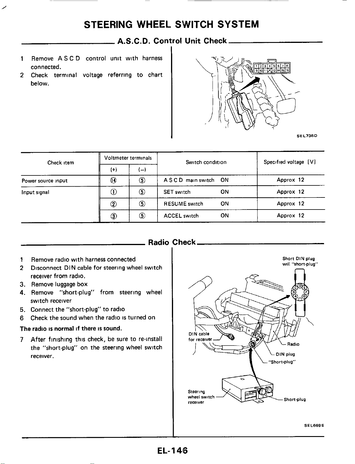
STEERING WHEEL SWITCH SYSTEM
Check item
A.S.C.D. Control Unit Check
Voltmeter terminals
(+I
(4
Switch condition Specified voltage
[VI
1
Remove AS C
D
control unit with harness
connected.
Power source input
Input
signal
SEL736D
0
0
AS C
D
main switch
ON
Approx 12
0
0
SET
switch
ON
Approx 12
0
0
RESUMEswitch
ON
Approx 12
ACCEL switch
ON
Approx 12
1
Remove radio with harness connected
2
Disconnect DIN cable for steering wheel switch
receiver from radio.
3.
Remove luggage
box
4.
Remove "short-plug" from steering wheel
switch receiver
5.
Connect the "short-plug" to radio
6
Check the sound when the radio
IS
turned on
The
radio
is
normal
if
there
is
sound.
7
After finishing this check,
be
sure to re-install
the "short-plug" on the steering wheel switch
receiver.
Short
DIN
plug
will
"short-plug"
Steering
Short-plug
wheel
switch
recBlYer
SEL669E
EL-
1
46
STEERING
WHEEL
SWITCH
SYSTEM
Note
EL-I
47
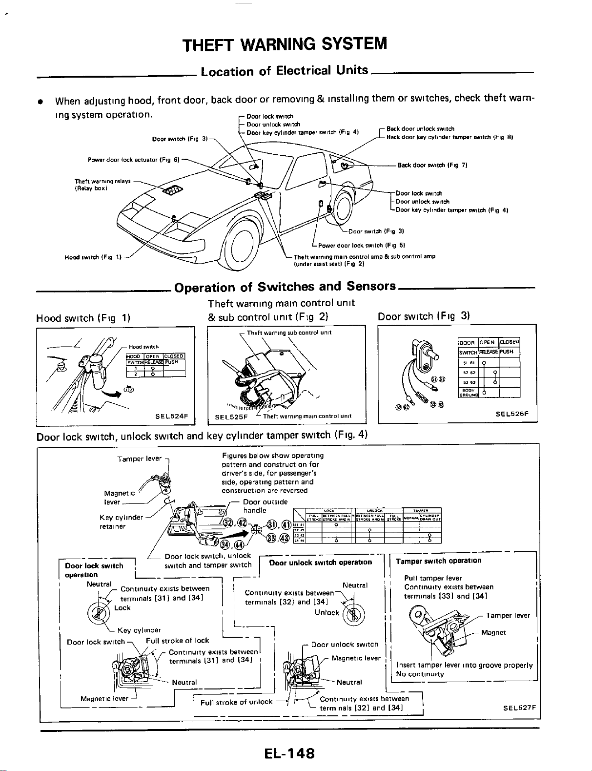
THEFT
WARNING
SYSTEM
Location
of
Electrical Units
When adjusting hood, front door, back door or removlng
&
installing them or switches, check theft warn-
ing system operation.
Bask
door
unlmk
wfch
Back
door
Lev
wlinder
timwr
witch
(Fig
81
r
fampr
witch IFSO
41
Door
m81ch
IFig
31
Powerdoor lock
actuator
IFrg
61
Back door
milch
lFig
71
Theft
wam,ng
,.l.Vf
IRclav
box1
Door
lock
mifh
Door
unlock
m#f&
Door
kev
cylinder limpr
mw11ch
IF89
4)
OO~
miUh
(Fig
31
Powor door lock
milch
(Fig
51
Hod
swwltsh
IFio
11
mehwmng
main
conlroI
amp
h
sub
control
amp
(under
assist
*it1
IF39
21
Operation
of
Switches and Sensors
Theft warning main control unit
&sub control unit (Fig
2)
Hood switch (Fig
1)
Door switch (Fig
3)
Door lock switch, unlock switch and key cyllnder tamper switch (Flg.
4)
Figures
below
show
Operating
pattern
and construction
for
driver's
side,
for
passenger's
ride,
operatmg
pattern
and
construction
are
reversed
retainer
Nnuity
exists
between
1
terminals
1331
and
1341
I
7
Key
cylinder
y"y,
.....-..
Continuity
exist6
between1
terminals
I311
and
I341
I
_-
Continuity
emts
between1
terminals
1321
and 1341
I
SI
EL-
1
4%
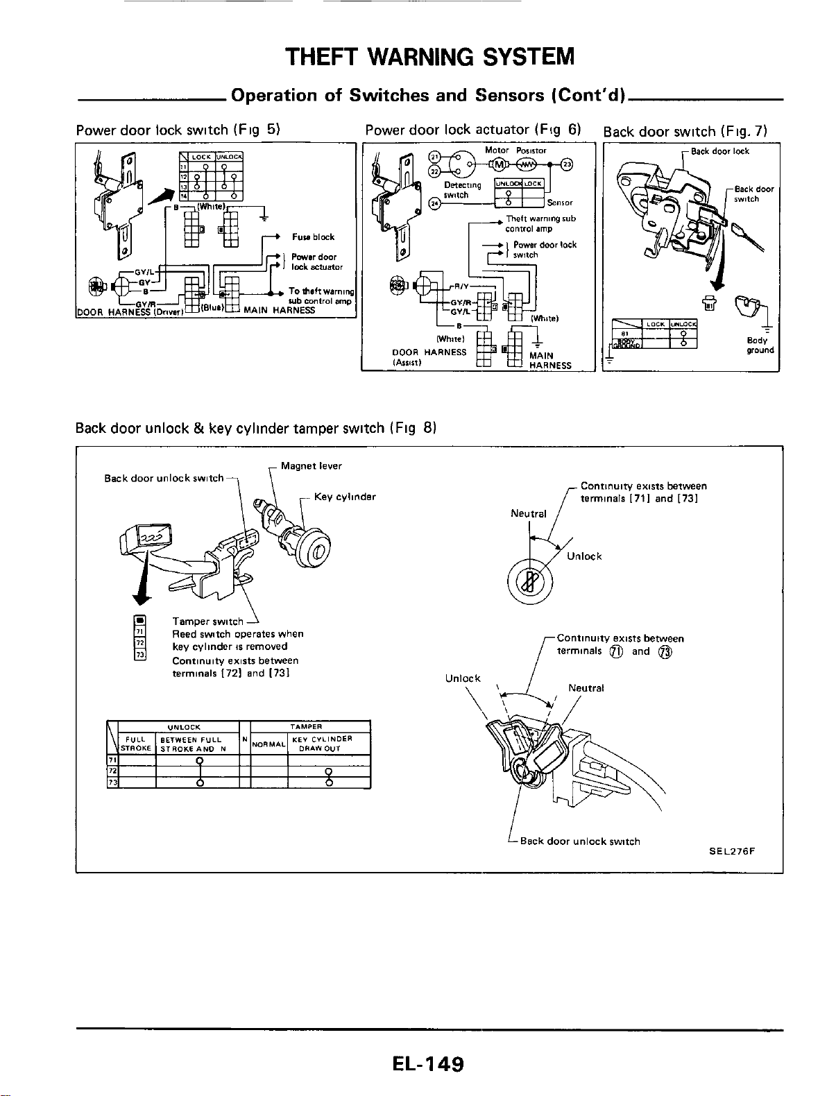
THEFT
WARNING
SYSTEM
Operation
of
Switches
and Sensors (Cont'd)
Power door lock swltch
(Flg
5)
Power door lock actuator
(Fig
6)
Back door switch
(Fig.
7)
OR
HARNESS
Back door unlock
&
key cylinder tamper switch
(Fig
8)
Back door unlock switch?
\
Magnet
level
Tamper switch
1
Reed witch operates when
1
key cylinder
15
removed
Contlnulty emti between
terminals
I721
and
[731
Continuity emts between
terminals
[711
and
[731
Neutral
Continuity extsts between
terminals
@)
and
@)
LBackdoor unlock wmh
SELZ76F
EL-149
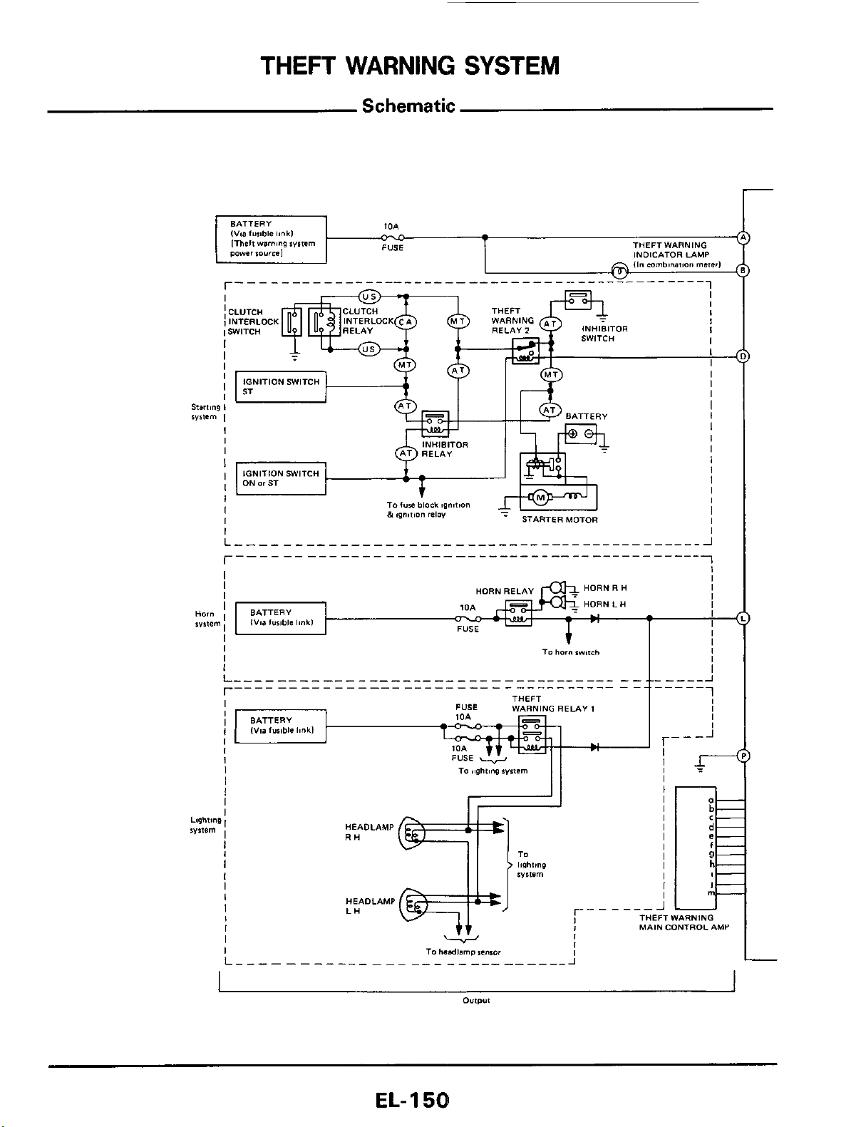
THEFT
WARNING
SYSTEM
Schematic
r
EL-
1
58
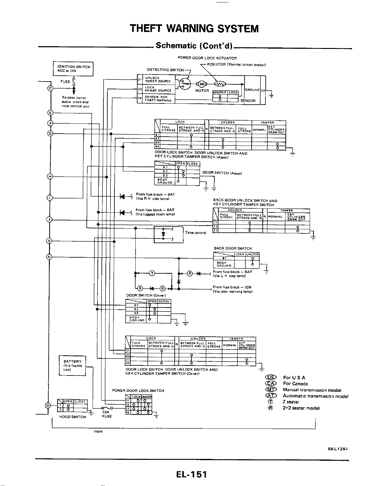
THEFT
WARNING
SYSTEM
Schematic
(Cont'd)
IGNITION
SWITCH
ACC
or
ON
Todoor mirror
audio
clock
and
*,me
mntro,
Y",,
84CK
DOOR
UNLOCKSW~TCH
AND
KEY CYLINDER
TAMPER
SWITcu
I
O
I
O
BACK
DOOR
SWITCH
I
I
KEY
CYLINDER TAMPER SWITCH
IDriwrl
a
POWER
DOOR
LOCKSWlTCH
Id
I,
I.
=kg-
FUSE
-
I
HooDSW'TCH
ForUSA
For
Canada
Manual
transmlsslon model
a
Automatic transmission model
0
2
seater
8
2+2
seater model
j
SEL128J
EL-I
51

THEFT
WARNING
SYSTEM
Wiring Diagram
.-
.
..
EL-I
52
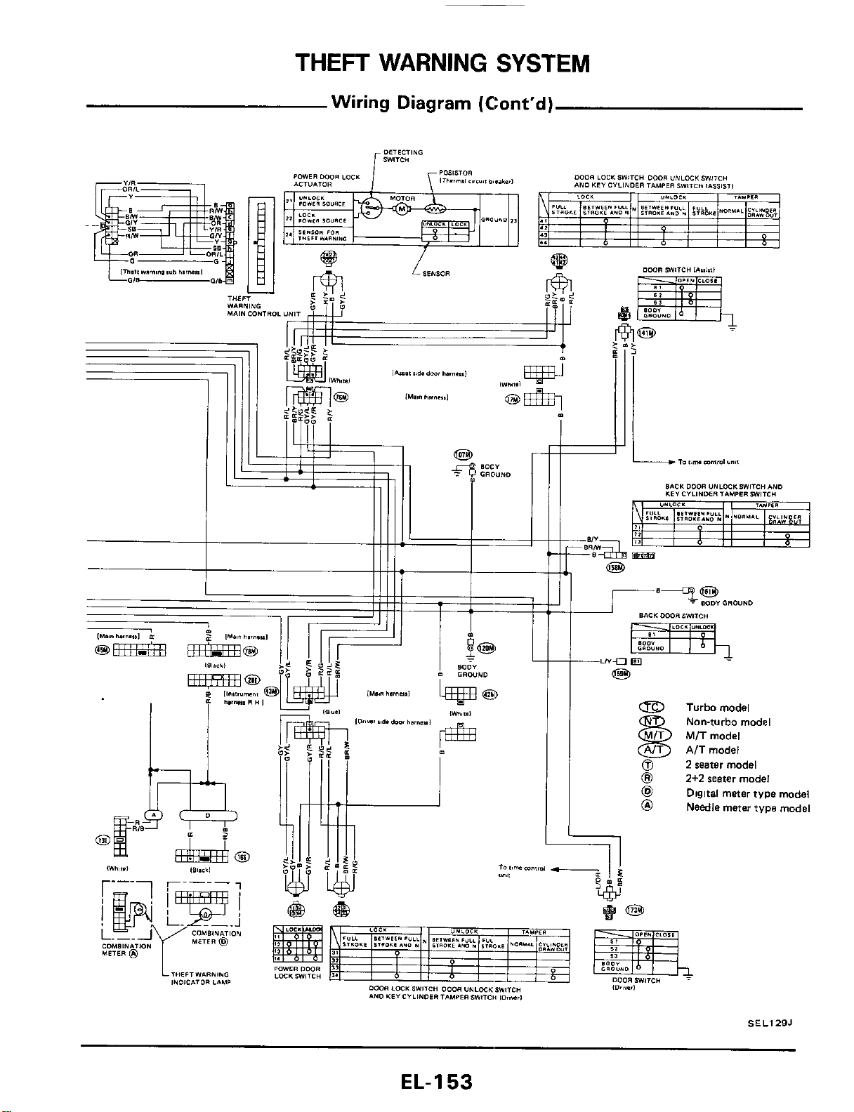
THEFT
WARNING
SYSTEM
Wiring Diagram (Cont'd)
&
Turbomodel
@
2
seater model
@I
2+2
water model
@
Digital meter tvpe model
@
Needle meter type model
Nan-turbo model
MIT model
AIT model
SEL129J
EL-I
53
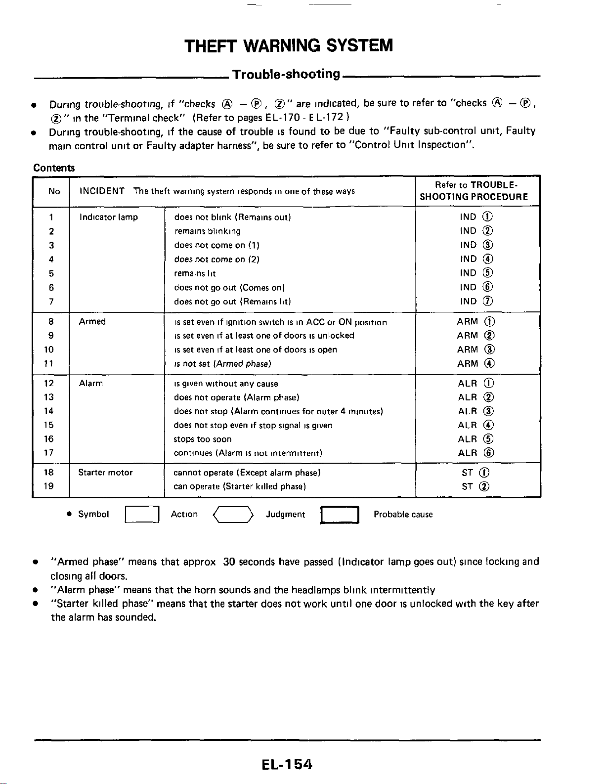
THEFT
WARNING
SYSTEM
Trouble-shooting
During trouble-shooting, if "checks
@
-
@
,
0''
are
indicated, be sure to refer to "checks
@
-
@
,
0''
in the "Terminal check" (Refer to pages EL-170
-
E
L-172
)
During trouble-shooting, if the cause
of
trouble
is
found to be due to "Faulty sub-control unit, Faulty
main control unit or Faulty adapter harness", be sure to refer to "Control Unit Inspection".
No INCIDENT The theft warning system responds in one of these ways
1
8
9
10
11
Indicator lamp
12
13
14
15
16
17
18
19
Armed
Alarm
Starter motoi
does not blink (Remains out)
remains blinking
does not come on
(1)
does not come
on
(2)
remains
lit
does not go out (Comes on)
does not go out (Remains
lit)
is
set
even if ignition switch
is
in ACC or ON position
is
set
even if
at
least
one of doors
is
unlocked
is
set
even if
at
least
one of doors
is
open
is
not
set
(Armed phase)
is
given without any cause
does not operate (Alarm phase)
does not stop (Alarm continues for outer 4 minutes)
does not stop even if stop signal
is
given
stops too soon
continues (Alarm
is
not intermittent)
cannot operate (Except alarm phase)
can operate (Starter killed phase)
Refer to TROUBLE-
SHOOTING PROCEDURE
IND
@
IND
@
IND
@
IND
@
IND
@
IND
@
IND
0
ARM
@
ARM
@
ARM
@
ARM
@
ALR
@
ALR
@
ALR
@
ALR
@
ALR
@
ALR
@
ST
@
ST
@
0
Symbol
U
Action
0
Judgment
1-1
Probable cause
"Armed phase" means that approx
30
seconds have passed (Indicator lamp goes
out)
since locking and
closing
all
doors.
"Alarm phase" means that the horn sounds and the headlamps blink intermittently
"Starter killed phase" means that the starter does not work until one door
is
unlocked with the key after
the alarm has sounded.
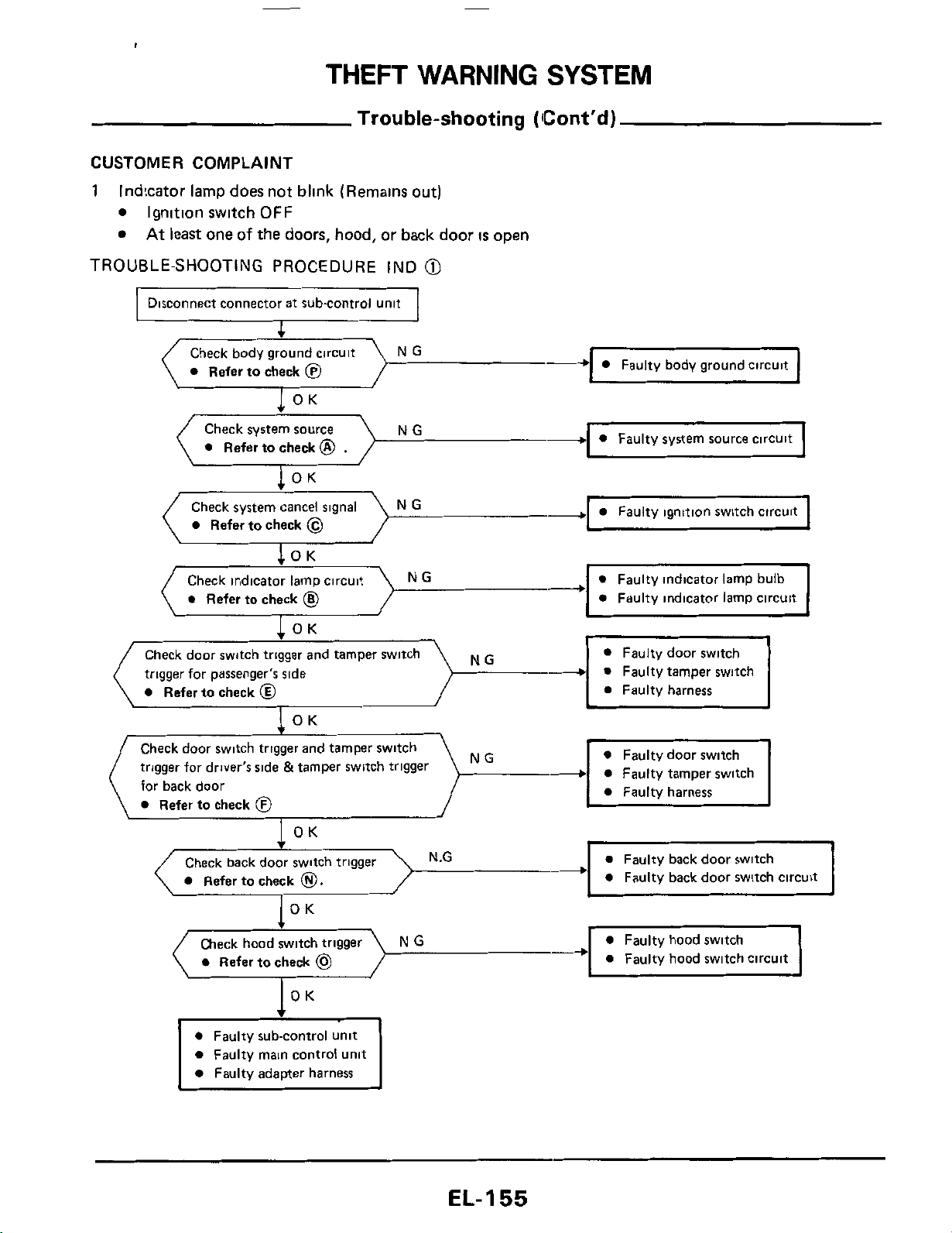
THEFT
WARNING
SYSTEM
Trouble-shooting
(Cont'd)
CUSTOMER
COMPLAINT
1
Indicator lamp does not blink (Remains out)
Ignition switch
OFF
At
least
one
of
the doors, hood, or back door
IS
open
TROUBLE-SHOOTING PROCEDURE IND
@
Disconnect connector at subcontrol unit
Check body ground circuit NG
0
Refer to check
@
OK
-
Faulty body ground circuit
NG
-
0
Faulty system source circuit
Check system source
0
Refer to check
@
.
I
OK
.
-
0
Faulty ignitron switch circurt
0
Refer to check
@
0
Faulty indicator lamp circuit
NG
0
Refer to check
@
trigger for passenger's side
0
Faulty tamper switch
Check door switch trigger and tamper switch
trigger for driver's side &tamper switch trigger
for back door
0
Refer to check
@
NG
Check back door switch trigger
Refer to check
0.
c
0
Refer to check
@
0
Faulty hood switch circuit
0
Faulty main control unit
0
Faulty adapter harness
EL-I
55
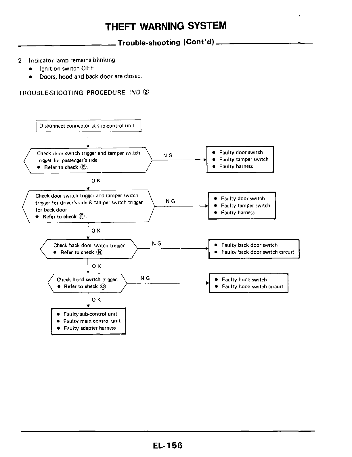
THEFT
WARNING
SYSTEM
Trouble-shooting (Cont'd)
2
Indicator
lamp
remains blinklng
Ignition switch
OFF
Doors,
hood
and back door are
closed.
TROUBLE-SHOOTING PROCEDURE
IND
@
1
Disconnect connector
at
subcontrol unit
I
Faulty tamper switch
NG
Check door switch
trigger for passenger's side
0
Refer to check
0.
OK
Check door switch trigger and tamper switch
trigger for driver's side
&
tamper swltch trigger
for back door
0
Refer to check
0.
NG
0
Faulty back door switch circuit
NG
0
Refer to check
0
OK
Check hood switch trigger.
0
Faulty hood switch
+---
0
Faulty hood switch circuit
0
Refer
to
check
@
0
Faulty main control unit
EL-I
56

THEFT
WARNING
SYSTEM
Trouble-shooting (Cont'd)
3
Indicator lamp does not come on
(1)
Ignition switch
OFF
Doors, hood and back door are closed.
After
closing
all
doors, doors
are
locked with
key
TROUBLE-SHOOTING PROCEDURE IND
@
Check to
see
if indicator lamp blinks while
opening any door
NG
Refer
to
"TROUBLE-SHOOTING
PROCEDURE IND
@"
OK
Check to
see
if indicator lamp goes out while
NG
Refer
to
"TROUBLESHOOTING
closing and unlocking
all
doors
PROCEDURE
IND
@-.
OK
Disconnect connector
at
subcontrol unit
0
Faulty power door lock actuator
Faulty harness
--+
0
Faulty power door lock switch
I
,
NG
1
Check power door lock trigger
Refer to check
@
0
Faulty power door lock actuator
0
Refer
to
check
@
0
Faulty harness
Check armed signal
NG
0
Faulty door lock switch
0
Refer
to
check
@
0
Faultv door lock circuit
I
1
0
Faulty indicator lamp circuit
0
Refer
to
check
@.
0
Faulty main control unit
0
Faulty adapter harness
EL-
1
57
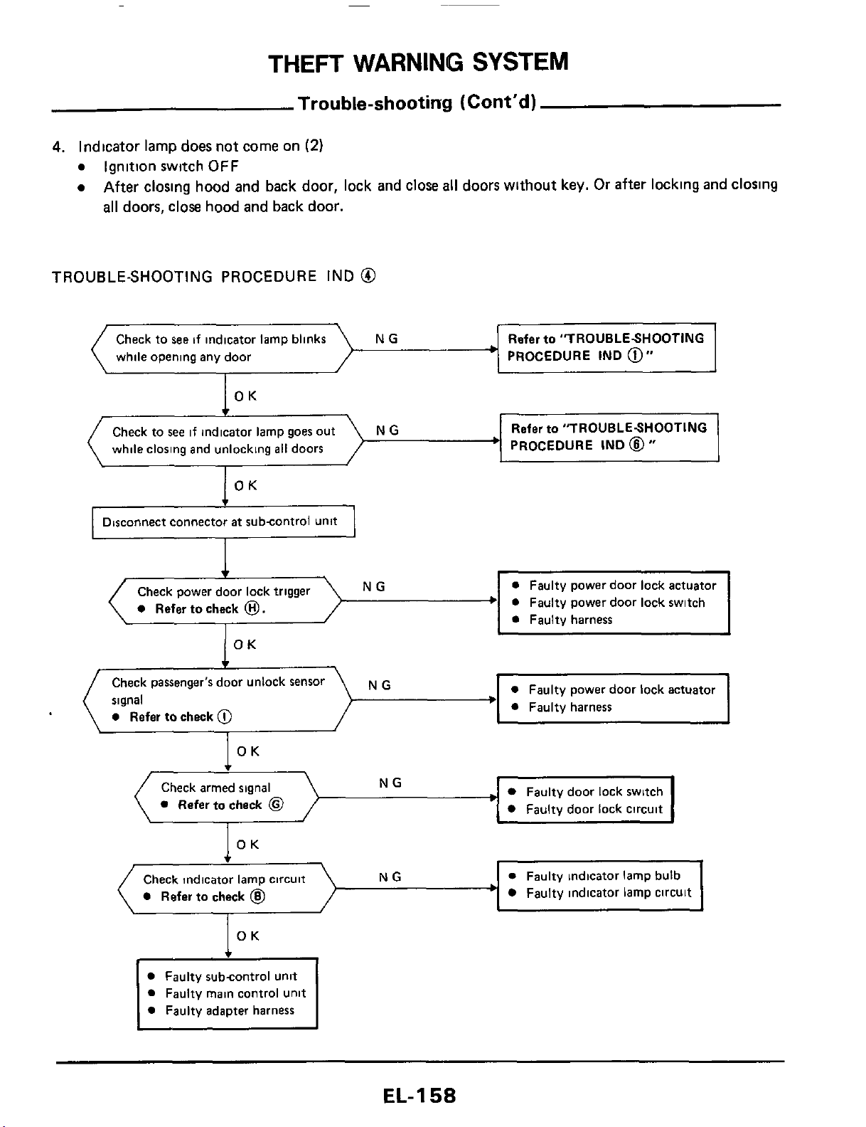
THEFT
WARNING
SYSTEM
Trouble-shooting
(Cont'd)
4.
Indicator lamp does not come on
(2)
a
Ignition switch
OFF
a
After closing hood and back door, lock and close
all
doors without
key.
Or after locking and closing
all
doors,
close hood and back door.
TROUBLE-SHOOTING
PROCEDURE
IND
@
NG Refer
to
"TROUBLESHOOTING
while opening any door
PROCEDURE IND
@"
OK
PROCEDURE
IND
@
"
Check to
see
if indicato
while closing and unlocking
all
doors
NG
OK
Disconnect connector
at
subcontrol Unit
NG
a
Refer
to
check
0.
OK
f
Check passenger's door unlock Sensor
signal
a
Refer
to
check
@
NG
\
OK
Check armed signal
Refer
to
check
@
Faulty door lock switch
Faulty door lock circuit
0
Faulty indicator lamp bulb
Faulty indicator lamp circuit
Check indicator lamp circuit
Refer
to
check
@
OK
Faulty subcontrol unit
Faulty main control unit
Faulty adapter harness
EL-I
58
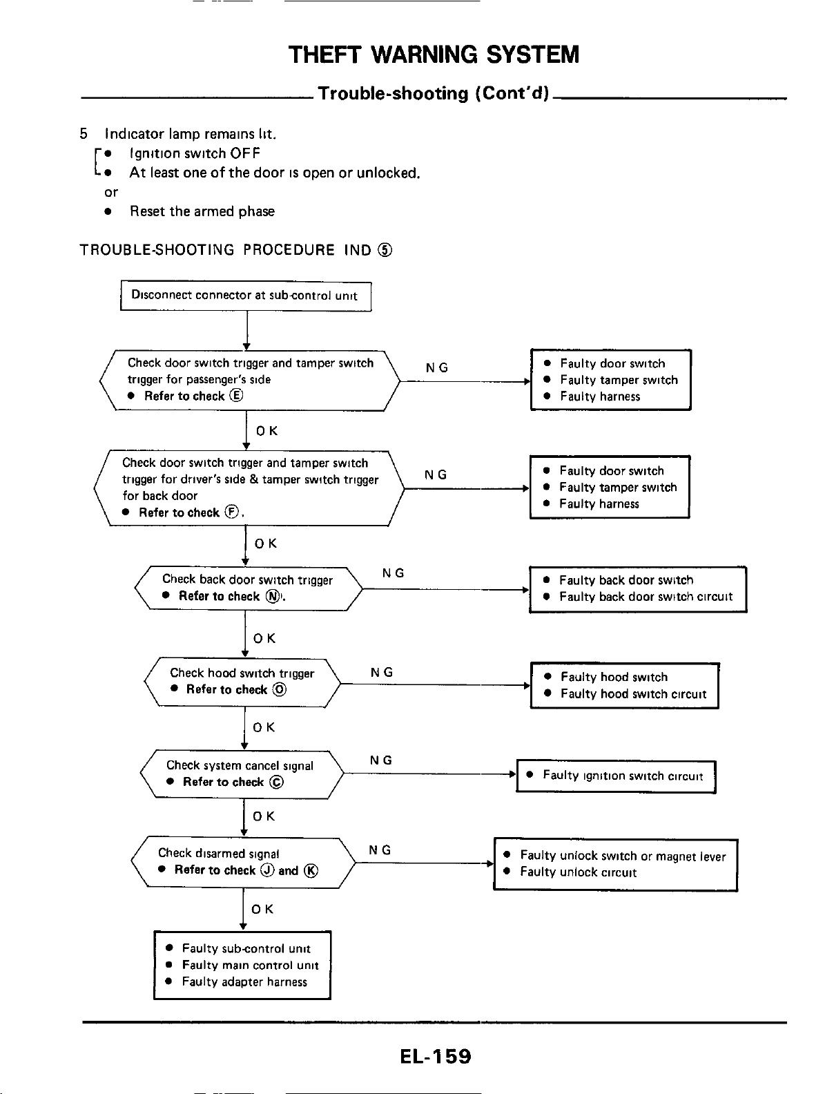
THEFT
WARNING
SYSTEM
Trouble-shooting (Cont'd)
5
Indicator lamp remains
lit.
Ignition switch
OFF
or
Reset
the armed phase
At
least one
of
the
door
is
open or unlocked,
[
TROUBLE-SHOOTING PROCEDURE IND
@
Disconnect connector
at
subcontrol unit
Faulty tamper switch
Check door switch
trigger for passenger's side
0
Refer to check
@
Check door switch trigger and tamper switch
trigger for driver's side &tamper switch trigger
for back door
Refer
to
check
0.
a
Faulty back door switch circuit
I
NG
Refer
to
check
01.
Faulty hood switch circuit
NG
Refer
to
check
@
Check system cancel signal
Refer to check
@
Refer
to
check
@
and
@
Faulty subcontrol unit
a
Faulty main control unit
0
Faulty adapter harness
EL-159
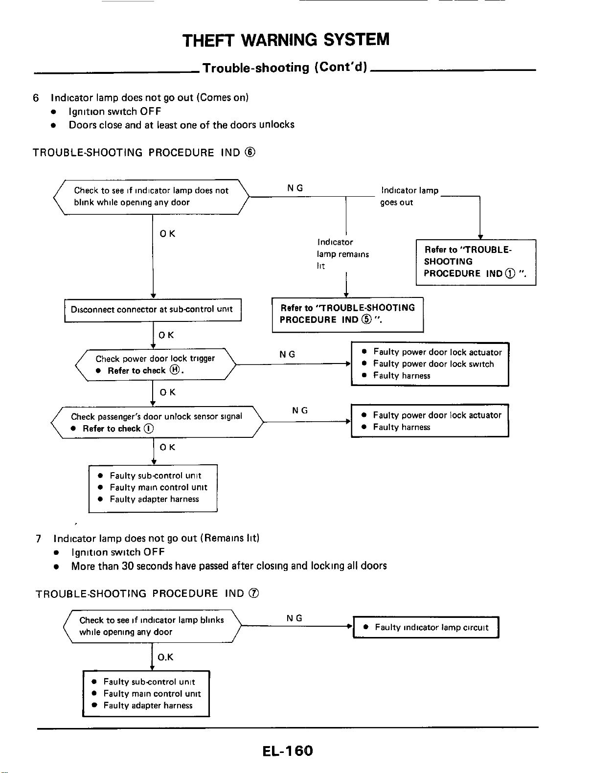
THEFT
WARNING
SYSTEM
Trouble-shooting
(Cont'dl
6
Indicator lamp
does
not go out (Comes on)
Ignition switch
OFF
Doors close and
at
least one of the doors unlocks
blink while opening any door
TROUBLESHOOTING PROCEDURE IND
@
1
goes out
OK
I
Indicator
lamp remains
lit
I
Refer to
"TROUBLE-
SHOOTING
PROCEDURE IND
@
".
PROCEDURE IND
0".
0
Faulty power door lock switch
0
Refer to check
0.
OK
NG
Check passenger's door unlock sensor signal
0
Refer to check
@
OK
0
Faulty subcontrol unit
0
Faulty main control unit
0
Faulty adapter harness
7
Indicator lamp does not
go
out (Remains
lit)
Ignition switch
OFF
More than
30
seconds have passed after closing and locking
all
doors
TROUBLE-SHOOTING PROCEDURE IND
@
Check to
see
if
indicator lamp blinks
while opening any door
NG
I
0
Faulty subcontrol unit
0
Faulty main control unit
Faulty adapter harness
EL-I
60
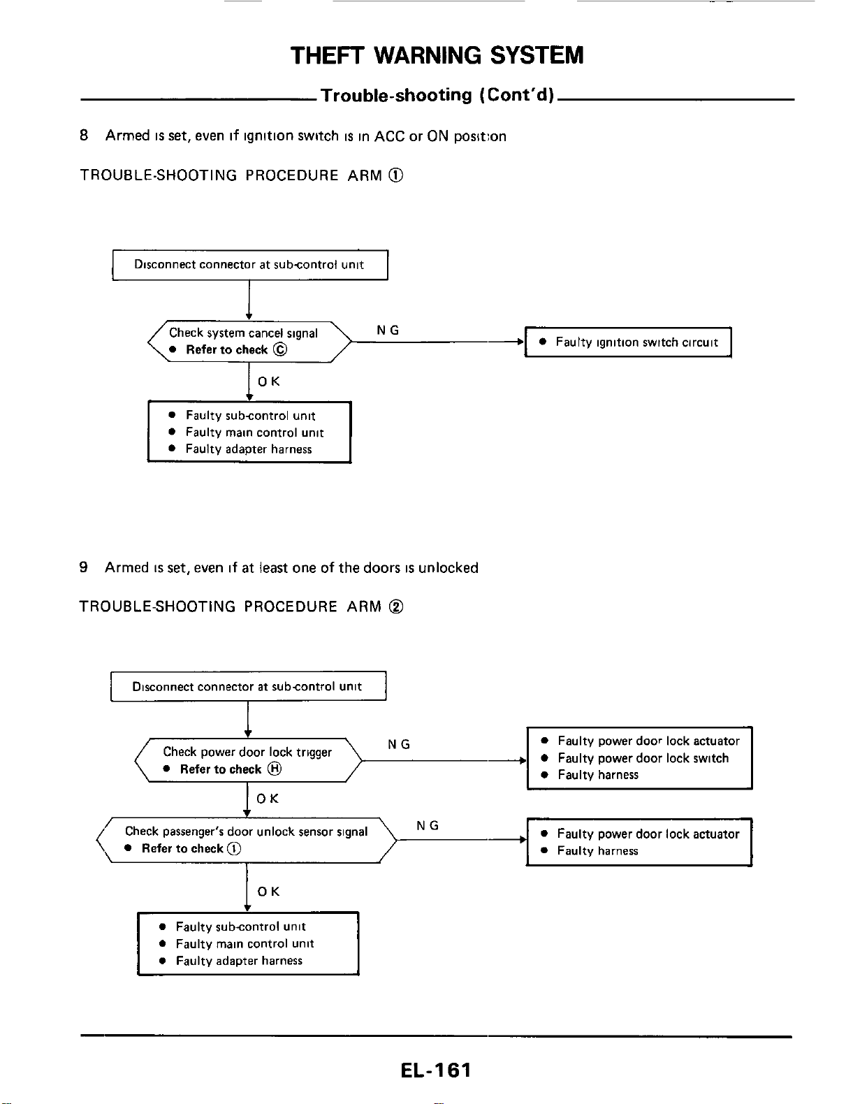
THEFT
WARNING
SYSTEM
Trouble-shooting
(Cont’d)
8
Armed
is
set, even if ignition switch
is
in ACC
or
ON position
TROUBLE-SHOOTING PROCEDURE ARM
@
I
Disconnect connector at subcontrol unit
I
I
-1
0
Faulty ignition switch circuit
\.
Referto check
@
7
OK
0
Faulty main control unit
9
Armed
IS
set,
even if
at
least one of the doors
is
unlocked
TROUBLE-SHOOTING PROCEDURE ARM
@
Disconnect connector
at
subcontrol unit
NG
Check power door lock trigger
0
Refer to check
@
OK
0
Faulty power door lock actuator
0
Faulty harness
NG
’
Check passenger‘s door unlock sensor signal
(,
Refertocheck@
I
0
Faulty subcontrol unit
0
Faulty main control unit
EL-I
61
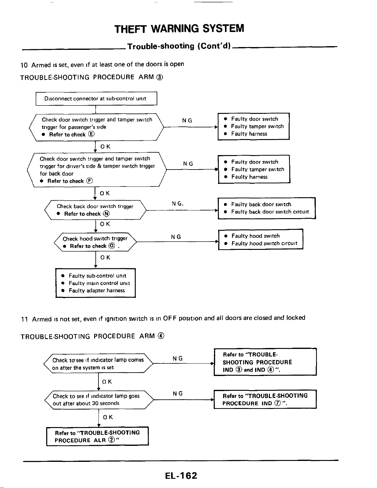
THEFT
WARNING
SYSTEM
Check door switch trigger and tamper switch
trigger for driver's side
&
tamper switch trigger
for back door
Refer to check
@
NG
Trouble-shooting
(Cont'd)
10
Armed
is
set,
even
if
at
least one of the doors
is
open
TROUBLE-SHOOTING PROCEDURE ARM
@
0
Faulty door switch
Faulty tamper switch
0
Faulty harness
~~
riisconnect connector
at
subcontrol unit
I
Check door switch trigger and tamper switch
trigger for passenger's side
+
a
Faulty tamper switch
Refer
to
check
@
a
Faulty harness
a
Faulty door switch
1
OK
a
Faulty back door switch
a
Faulty back door switch circuit
1
OK
Check back door swit
Refer to check
@
OK
.
I
NG
a
Faulty hood switch
Check hood switch trigger
a
Faulty hood switch circuit
I
OK
t
0
Faulty sub-control unit
0
Faulty main control unit
0
Faulty adapter harness
11
Armed
is
not set, even
if
ignition switch
IS
in
OFF
position and
all
doors are closed and
locked
TROUBLE-SHOOTING PROCEDURE ARM
@
Refer
to
"TROUBLE.
SHOOTING PROCEDURE
IND
@
and
IND
@
".
Check
tusee
if indicator lamp comes
on after the system
IS
set
Refer
to
"TROUBLE-SHOOTING
PROCEDURE
IND
0".
out after about
30
seconds
OK
Refer
to
"TROUBLE-SHOOTING
PROCEDURE
ALR
0"
EL-I
62
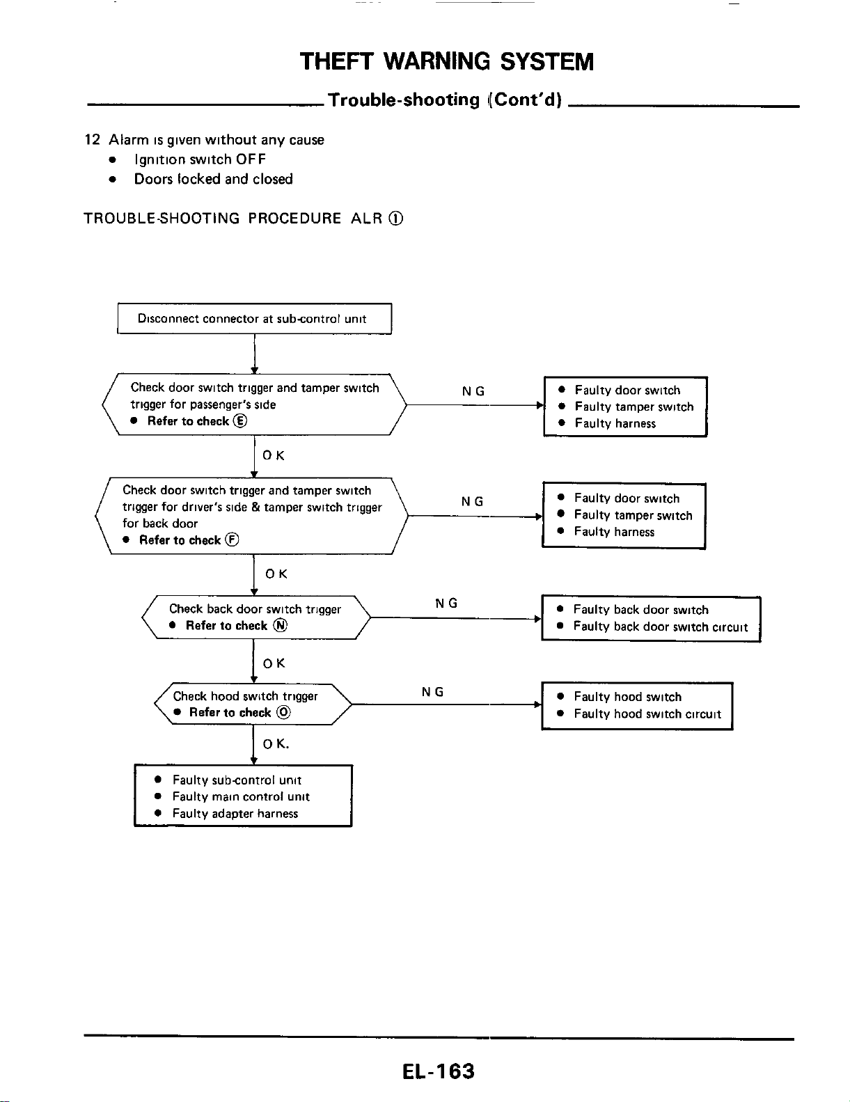
THEFT
WARNING
SYSTEM
Trouble-shooting
I[
Cont’d)
12
Alarm
is
given without any cause
0
Ignition switch
OFF
0
Doors locked and closed
TROUBLESHOOTING PROCEDURE ALR
@
I
Disconnect connector
at
subcontrol unit
I
0
Faulty tamper switch
I
Check door switch
trigger for passenger’s side
Refer to check
@
Check door switch trigger and tamper switch
trigger for driver’s side
&
tamper switch trigger
for back door
0
Refer
to
check
@
Faulty tamper switch
OK
Check back door switch trigger
0
Refer
to
check
@
OK
NG
0
Faulty back door switch
Faulty back door switch circuit
c
Check hood switch trigger
NG
0
Faulty hood switch
Refer
to
check
@
0
Faulty hood switch circuit
L
I
L
1
0
K.
0
Faulty subcontrol unit
0
Faulty main control unit
0
Faulty adapter harness
EL-I
63
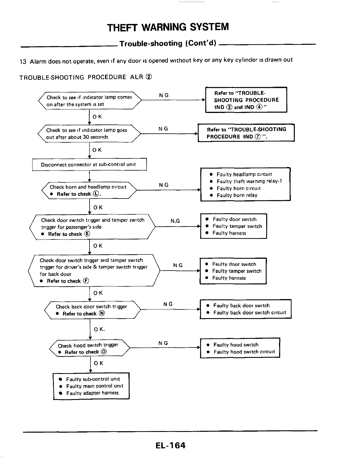
THEFT
WARNING
SYSTEM
Trouble-shooting (Cont'd)
13
Alarm
does
not operate, even
if
any door
IS
opened without key or any key cyllnder
IS
drawn
out
TROUBLE-SHOOTING PROCEDURE ALR
@
-,
NG
0
Refer
to check
0.
Refer
to
"TROUBLE.
SHOOTING PROCEDURE
IND
@
and
IND
,@"
Check
to
see
if
indicator lamp comes
on
after
the system
IS
set
NG
OK
Check to
see
if indicator lamp goes
out after about
30
seconds
Refer
to
"TROUBLE-SHOOTING
PROCEDURE
IND
@
".
I
0
Faulty headlamp circuit
0
Faulty theft warnlng relay-1
0
Faulty horn circuit
0
Faulty horn relay
I
Disconnect connector
at
subcontrol unit
I
Check door switch trigger and tamper switch
trigger for passenger's side
b
0
Refer
to
check
@
N
.G
Faulty door switch
Faulty tamper switch
0
Faulty harness
Faulty subcontrol unit
0
Faulty main control unit
Faulty adapter harness
Check door switch trigger and tamper switch
trigger for driver's side &tamper switch trigger
for back door
0
Refer
to
check
0
NG
b
EL-I
64
0
Faulty door switch
0
Faulty tamper switch
0
Faulty harness
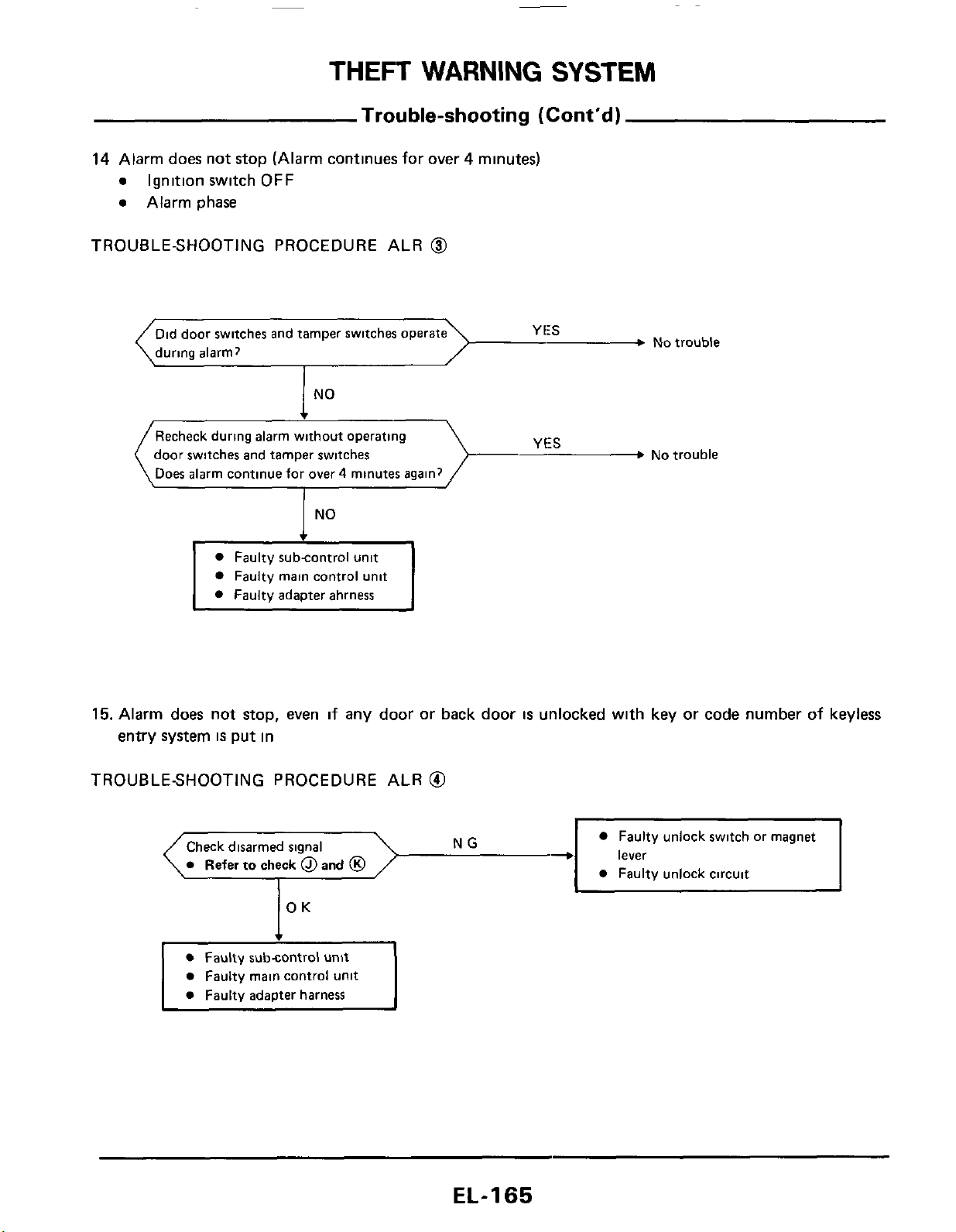
THEFT
WARNING
SYSTEM
Trouble-shooting
(Cont’d)
14 Alarm does not stop (Alarm continues for over 4 minutes)
e
Ignition switch
OFF
e
Alarm phase
TROUBLE-SHOOTING PROCEDURE ALR
@
Did door switches and tamper switches
during alarm?
No
trouble
NO
__3
No
trouble
Recheck during alarm without operating
door switches and tamper switches
Does alarm continue for over
4
minutes again?
I
No
Faulty subcontrol unit
Faulty main control unit
Faulty adapter ahrness
15. Alarm does not
stop,
even if any door
or
back door
is
unlocked with key or code number of keyless
entry system
is
put in
TROUBLESHOOTING PROCEDURE ALR
@I
Faulty unlock switch or magnet
lever
Check disarmed signal
EL-I
65
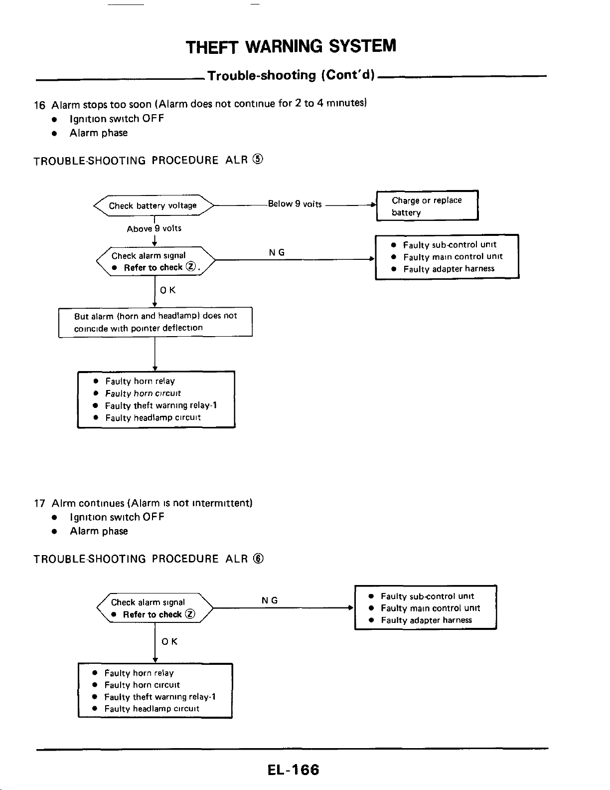
THEFT
WARNING
SYSTEM
Trouble-shooting
(Cont'd)
16
Alarm stops too soon (Alarm
does
not continue
for
2
to
4
minutes)
Ignition switch
OFF
Alarm phase
TROUBLE-SHOOTING
PROCEDURE ALR
@
Below
9
volts
Above
9
VOltS
Check alarm signal
0
Faulty main control Unit
0
Faulty horn relay
0
Faulty horn circuit
Faulty theft warning relay-1
0
Faulty headlamp circuit
17
Alrm continues (Alarm
is
not intermittent)
Ignition switch
OFF
Alarm phase
TROUBLESHOOTING PROCEDURE ALR
8
0
Faulty subcontrol unit
0
Faulty main control unit
0
Faulty adapter harness
0
Refer
to
check
0
0
Faulty horn circuit
0
Faulty theft warning relay1
0
Faulty headlamp circuit
~
EL-I
66
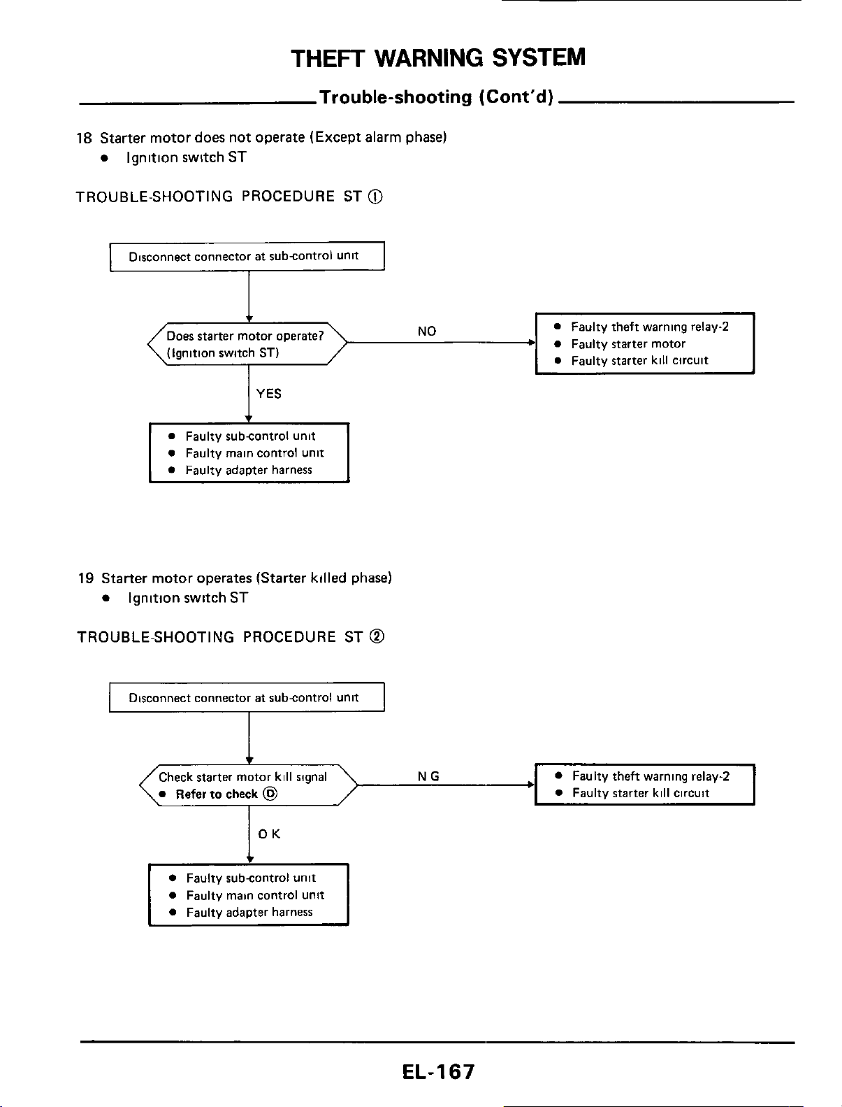
THEFT
WARNING
SYSTEM
Check starter motor kill signal
0
Refer
to
check
@
Trouble-shooting
(Cont'd)
18
Starter motor does not operate (Except alarm phase)
Ignition switch ST
TROUBLE-SHOOTING PROCEDURE ST
@
0
Faulty theft warning relay-2
0
Faulty
starter
kill circuit
Disconnect connector
at
subcontrol unit
+
0
Faulty
starter
motor
c
(Ignition switch
ST)
0
Faulty main control unit
0
Faulty adapter harness
19
Starter motor operates
(Starter
killed phase)
Ignition switch
ST
TROUBLE-SHOOTING PROCEDURE ST
@
I
Disconnect connector
at
subcontrol unit
I
0
Faulty subcontrol unit
0
Faulty main control unit
0
Faulty adapter harness
EL-I67
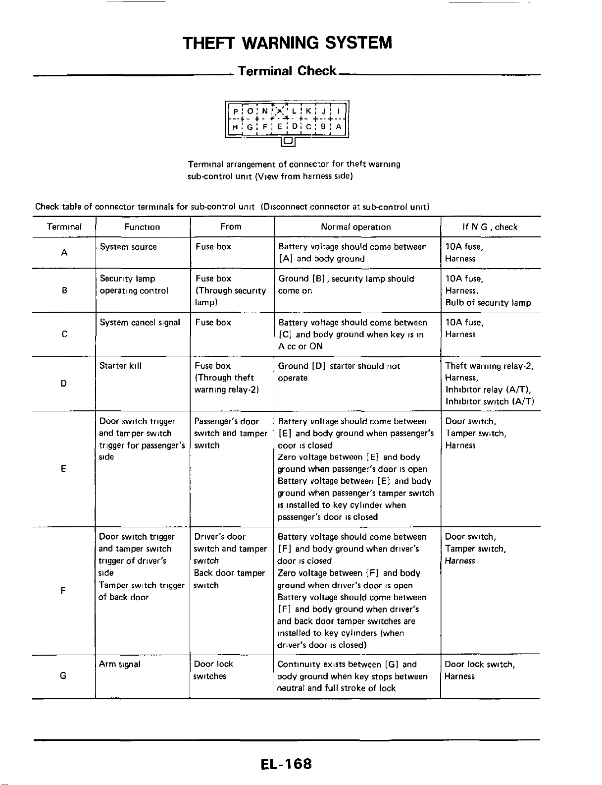
THEFT
WARNING
SYSTEM
Terminal
Check
-.+.
+.
+'.a.
+-
+-.+-.
H:G:
FI
E:
D:
C:
BI
A
Terminal arrangement of connector for theft warning
sub-control unit (View from harness side)
Check table of connector terminals for sub-control unit (Disconnect connector
at
sub-control unit)
Terminal
~~
Function
System source
Security lamp
operating control
Normal operation
From
Fuse box
Fuse box
(Through security
lamp)
Fuse box
If
N
GI
check
10A fuse,
Harness
1
OA fuse,
Harness,
Bulb of security lamp
~ ~
Battery voltage should come between
[AI and body ground
Ground [El, security lamp should
come
on
A
B
C
System cancel signal Battery voltage should come between
IC]
and body ground when key
is
in
A cc or ON
10Afuse.
Harness
Starter kill
Fuse box
(Through theft
warning relay21
Ground
[Dl
starter should not
operate
Theft warning relay-2,
Harness,
Inhibitor relay (A/T),
Inhibitor switch (A/T)
D
Door switch trigger
and tamper switch
trigger for passenger's
side
~ ~
Battery voltage should come between
[El
and body ground when passenger's
door
is
closed
Zero voltage between
[El
and body
ground when passenger's door
is
open
Battery voltage between [E] and body
ground when passenger's tamper switch
is
installed to key cylinder when
passenger's door
is
closed
Door switch,
Tamper switch,
Harness
Passenger's door
switch and tamper
switch
E
Door switch trigger
md tamper switch
trigger of driver's
;ide
Tamper switch trigger
>f
back door
Driver's door
switch and tamper
witch
Back door tamper
switch
Battery voltage should come between
[Fl
and body ground when driver's
door
IS
closed
Zero voltage between
[FI
and body
ground when driver's door
is
open
Battery voltage should come between
[F] and body ground when driver's
and back door tamper switches are
installed to key cylinders (when
driver's door
is
closed)
Door switch,
Tamper switch,
Harness
F
G
4rm signal Door lock
switches
Continuity exists between [GI and
body ground when key stops between
neutral and full stroke of lock
Door lock switch,
Harness
EL-
1
68
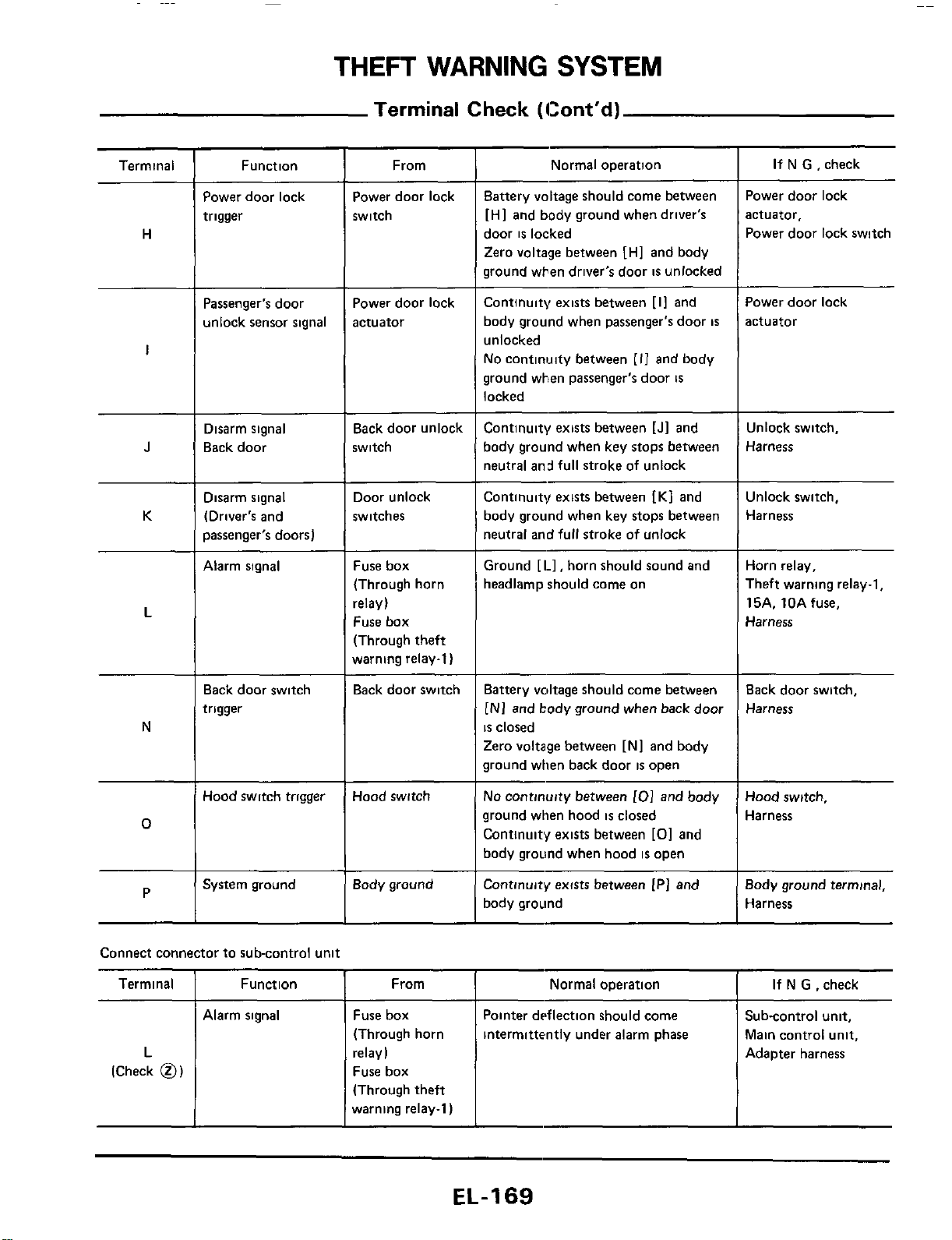
THEFT
WARNING
SYSTEM
Terminal
Check
(Cont‘d)
Terminal
I
Function From
~~
Normal operation
Normal operation
If
N
G ,check
If
N
G ,check
Pointer dtsflection should come
intermittently under alarm phase
i
Terminal
Function
From
Power door lock
trigger
Power door lock
switch
Battery voltage should come between
[HI and body ground when driver’s
door
is
locked
Zero voltage between [HI and body
ground when driver’s door
is
unlocked
Continuity exists between [I1 and
body ground when passenger’s door
is
unlocked
No continwty between
[I1
and body
ground when passenger’s door
is
locked
Power door lock
actuator,
Power door lock switch
H
Power door lock
actuator
Power door lock
actuator
Passenger‘s door
unlock sensor signal
I
Disarm signal
Back door
Back door unlock
switch
Continuity exists between [Jl and
body ground when key stops between
neutral and full stroke
of
unlock
Unlock switch,
Harness
J
K
Disarm signal
(Driver‘s and
passenger’s doors)
Door unlock
switches
Continuity exists between
IK1
and
body ground when key stops between
neutral and full stroke of unlock
Unlock switch,
Harness
Alarm signal Fuse box
(Through horn
relay)
Fuse box
(Through theft
warning relay-1)
Ground [I.], horn should sound and
headlamp should come on
Horn relay,
Theft warning relay-1,
15A. 10Afuse.
Harness
L
Back door switch,
Harness
Back door switch
trigger
Back door switch Battery voltage should come between
[NI
and body ground when back door
is
closed
Zero voltage between [Nl and body
ground when back door
is
open
No
continuity between
101
and body
ground when hood
is
closed
Continuity exists between
[O]
and
body ground when hood
is
open
Continuity exists between [PI and
body ground
N
Hood switch trigger Hood switch
Hood switch,
Harness
0
Body ground
Body ground terminal,
Harness
P
~~ ~
System ground
Alarm signal Fuse box
(Through horn
relay)
Fuse box
(Through theft
warning relay-1)
Sub-control unit.
Main control unit,
Adapter harness
L
(Check
0)
EL-169
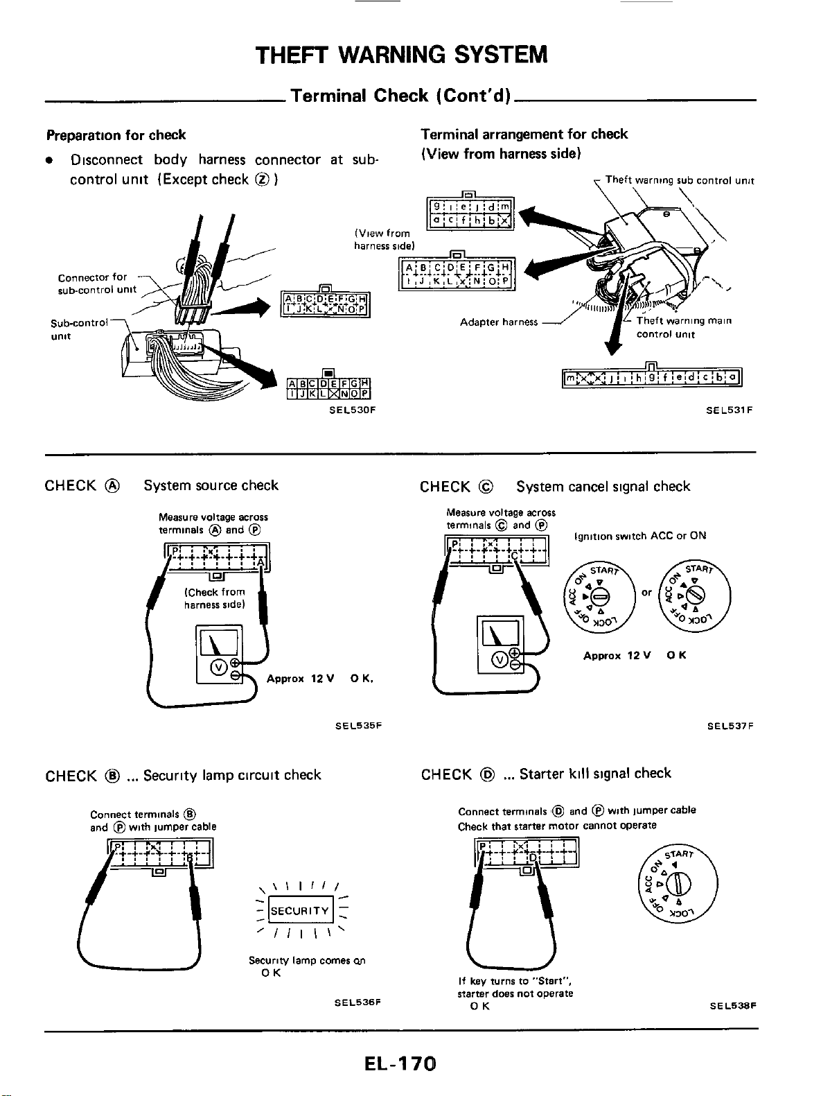
THEFT
WARNING
SYSTEM
Terminal Check (Cont'd)
Preparation for check
Disconnect body harness connector
at
sub-
Terminal arrangement
for
check
(View
from
harness
side)
control unit (Except check
@
)
Theft
warning
rub control unjt
connector
for
sub-control unit
Sub-control7
'
w-
U"lt
CHECK
@
System source check CHECK
@
System cancel signal check
Measure voltage across
terminals
@
and
@
(Check from
harness side)
Approx
12
v
0
K.
SEL535F
Ignition switch
ACC
or
ON
Approx
12V
OK
CHECK
@
...
Security lamp circuit check
CHECK
@
...
Starter
kill
signal check
Connect terminals
6
and
fi4
with
IumDer cable
\\I
1111
'/Ill\'
-
SECURITY
1
-0-
-
Securiw lamp comes
M
OK
SEL536F
Connect terminals
Check that starter motor cannot operate
and @with jumper cable
SEL537F
If
key
turn6 to "Start",
starter doer not operate
OK
SEL538F
EL-I
70
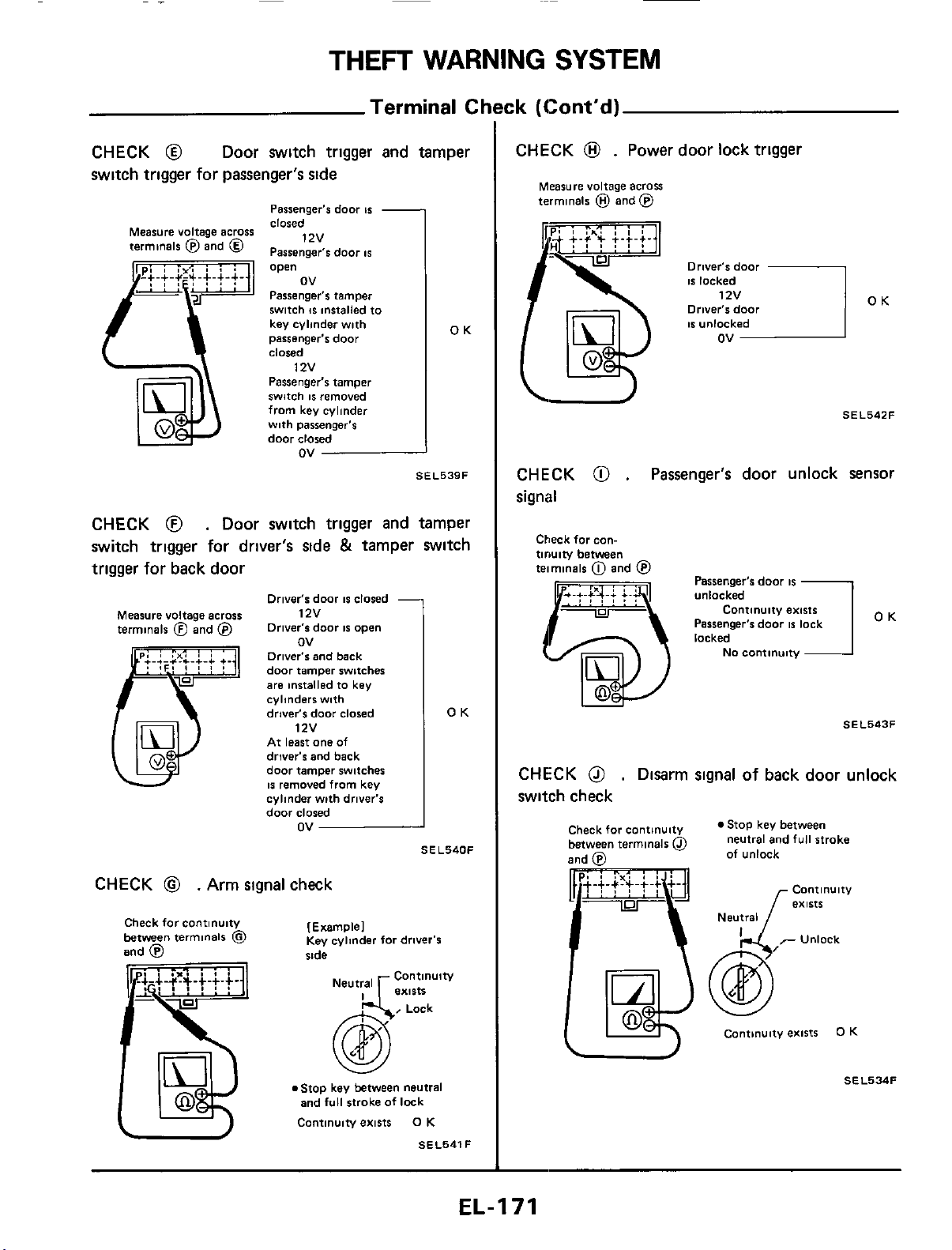
THEFT
WARNING
SYSTEM
-
Terminal
Ck
CHECK
@
Door switch
trigger
and tamper
switch trigger for passenger's
side
I
Passenger's door
IS
closed
OK
Measure voltage across
terminals @and
@
1zv
Passenger's door
IS
I
Passenger's tamper
switch
IS
installed to
key cylinder with
passenger's
door
closed
Passenger's tamper
switch
IS
removed
from key cylinder
with passenger's
door
closed
12v
ov
OK
SEL539F
CHECK
@
.
Door switch trigger and tamper
switch trigger for driver's side
&
tamper switch
trigger for back door
Driver's door
IS
closed
Orlver's door
IS
open
Measure voltage across
12v
terminals
@
and
@
ov
Driver's
and back
door tamper switches
are installed to key
cylinders with
driver's
door
closed
1
zv
At least
one
of
driver's and back
door tamper switcher
IS
removed from key
cylinder with driver's
door
closed
ov
SEL540F
CHECK
@
.
Arm signal check
Check forcontinuity
between
terminals
@
and
@
[Example1
Key
cylinder for driver's
side
@
Lock
.Stop key between neutral
and
full
stroke of lock
Continuiw exists
0
K
SEL541F
:k
(Cont'd)
CHECK
@
.
Power door lock trigger
Measure voltage across
terminals
@
and
@
Driver's
door
IS
locked
Driver's
door
ov
OK
SEL542F
\I
CHECK
@
.
Passenger's door unlock sensor
signal
Check
forean-
tiruiw
between
teimmals
0
and
@
Passenger's door
IS
U
OK
SEL543F
CHECK
@
.
Disarm signal of back door unlock
switch check
Check for continuity
between terminals
@
Stop key between
neutral and
full
stroke
of unlock
Contlnulty
exists
Neutral
cantmuity exists
0
K
-
SEL534F
EL-I71
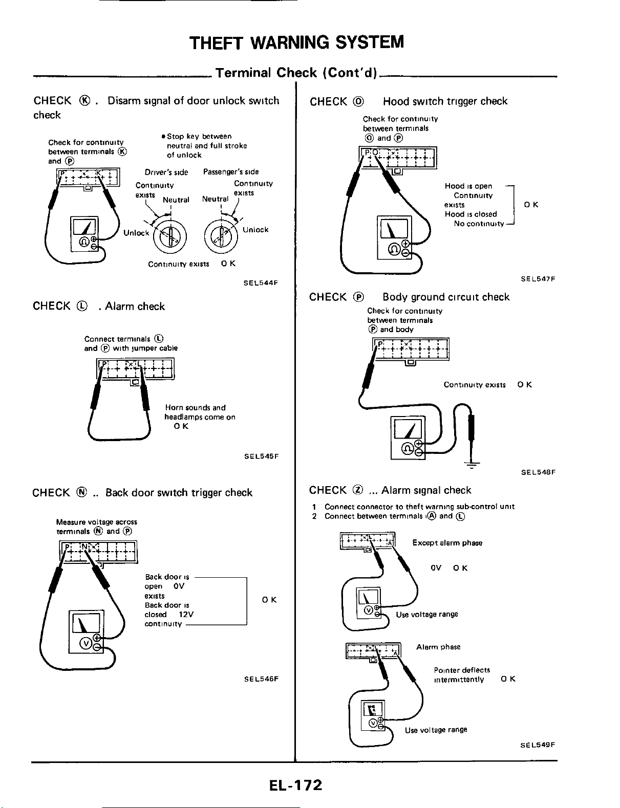
THEFT
WARNING
SYSTEM
Terminal CI
CHECK
0
.
Disarm
signal
of
door unlock switch
check
.Stop key between
neutral and full stroke
of unlock
Check far continuity
between terminals
@
Driver's ride Passenger's side
C0"tl""ltV
Unlock
Continuity
exists
0
K
SEL544F
CHECK
@
. Alarm check
Connect terminals
0
and
@
with jumper cable
.i.;
C?J;Lt.+.f.
Horn
sounds and
/TO
headlamps
K
come
on
U
SEL545F
CHECK
@
..
Back door switch trigger check
Measure voltage
across
terminals
@
and
@
Back door
IS
Back door
IS
open
OV
exists
OK
-
SEL546F
ck
(Cont'd)
CHECK
@
Hood switch trigger check
Check for continuitv
between terminals
(d,
and
@)
Hood
IS
open
Contlnulty
exists
Hood
IS
closed
1
OK
No
continuity
SE L547
F
U
CHECK
@
Body ground circuit check
Check far cantlnulty
between terminals
@
and body
CHECK
@
,..
Alarm signal check
1
Connect connector to theft warning subcontrol Unit
2
Connect between terminals
t@
and
0
OV OK
Use voltage range
Tyarm phase
Polnter deflects
intermittently
0
K
use voltage range
SEL549F
EL-I
72
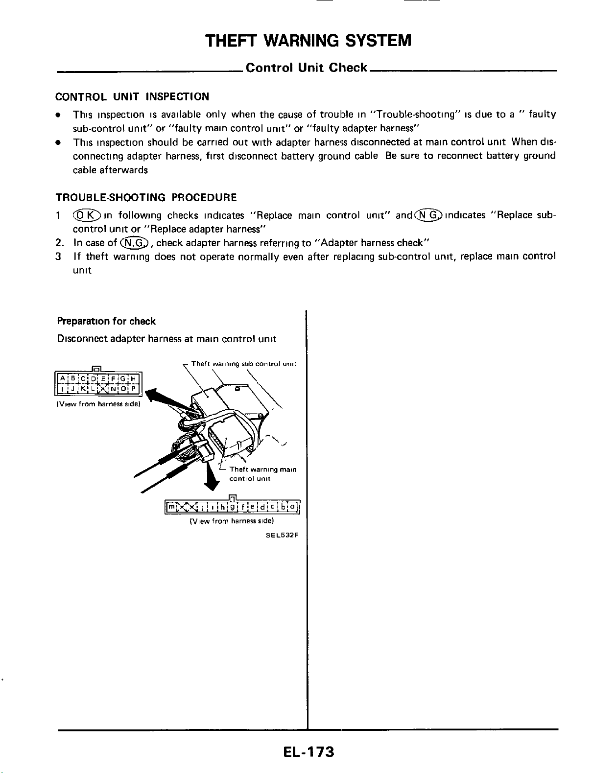
THEFT
WARNING
SYSTEM
Control Unit Check
CONTROL UNIT INSPECTION
0
This inspection
is
available
only when the cause of trouble in "Trouble-shooting"
is
due to
a
"
faulty
sub-control unit" or "faulty main control unit" or "faulty adapter harness"
This inspection should be carried out with adapter harnew disconnected
at
main control unit
When
dis-
connecting adapter harness, first disconnect battery ground cable
Be
sure to reconnect battery ground
cable afterwards
TROUBLE-SHOOTING PROCEDURE
1
Din following checks indicates "Replace main control unit" andm indicates "Replace
sub-
control unit or "Replace adapter harness"
2.
In case of
a,
check adapter harness referring to "Adapter harness check"
3
If theft warning does not operate normally even after replacing sub-control unit, replace main control
unit
Preparation for check
Disconnect adapter harness
at
main control unit
Theft
warning
rub
control
unit
(View
from
harness
side)
SEL532F
EL-I
73
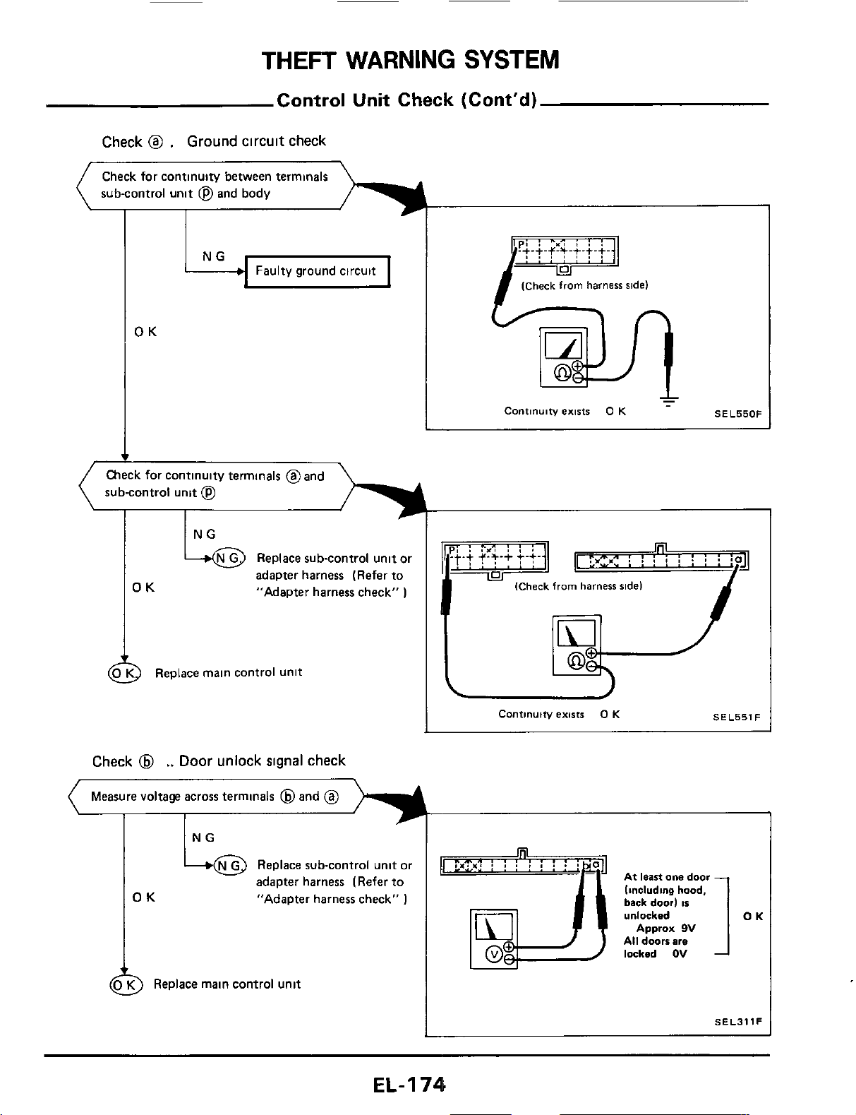
THEFT
WARNING
SYSTEM
Control
Unit
Check (Cont'd)
Check
@
.
Ground
circuit
check
Check for continuity between terminals
sub-control
unit
@
and body
Faulty ground circuit
OK
sub-control unit
@
adapter harness (Refer to
OK
"Adapter harness check"
)
2
Replace main control unit
Check
@
..
Door
unlock
signal
check
(
Measure voltage across terminals
@
and
@
L
4
OK
NG
+@
Replace sub-control unit or
adapter harness (Refer to
"Adapter harness check"
1
9
Replace main control unit
(Check
from
harness
ride)
Continuity
exists
0
K
-
SEL550F
I
ql
:P,"
:
!
:
i
:
!
i
:
ja
(Check
from
harness
ridel
I
(Check
from
harness
ridel
M-'
Continuity
exists
0
K
SEL551F
rq
or?*:
I
I
I
,
I
.
.
'
'
1
At
leastonedoor
linclvdine
hood,
back
door)
is
SELJllF
EL-I
74
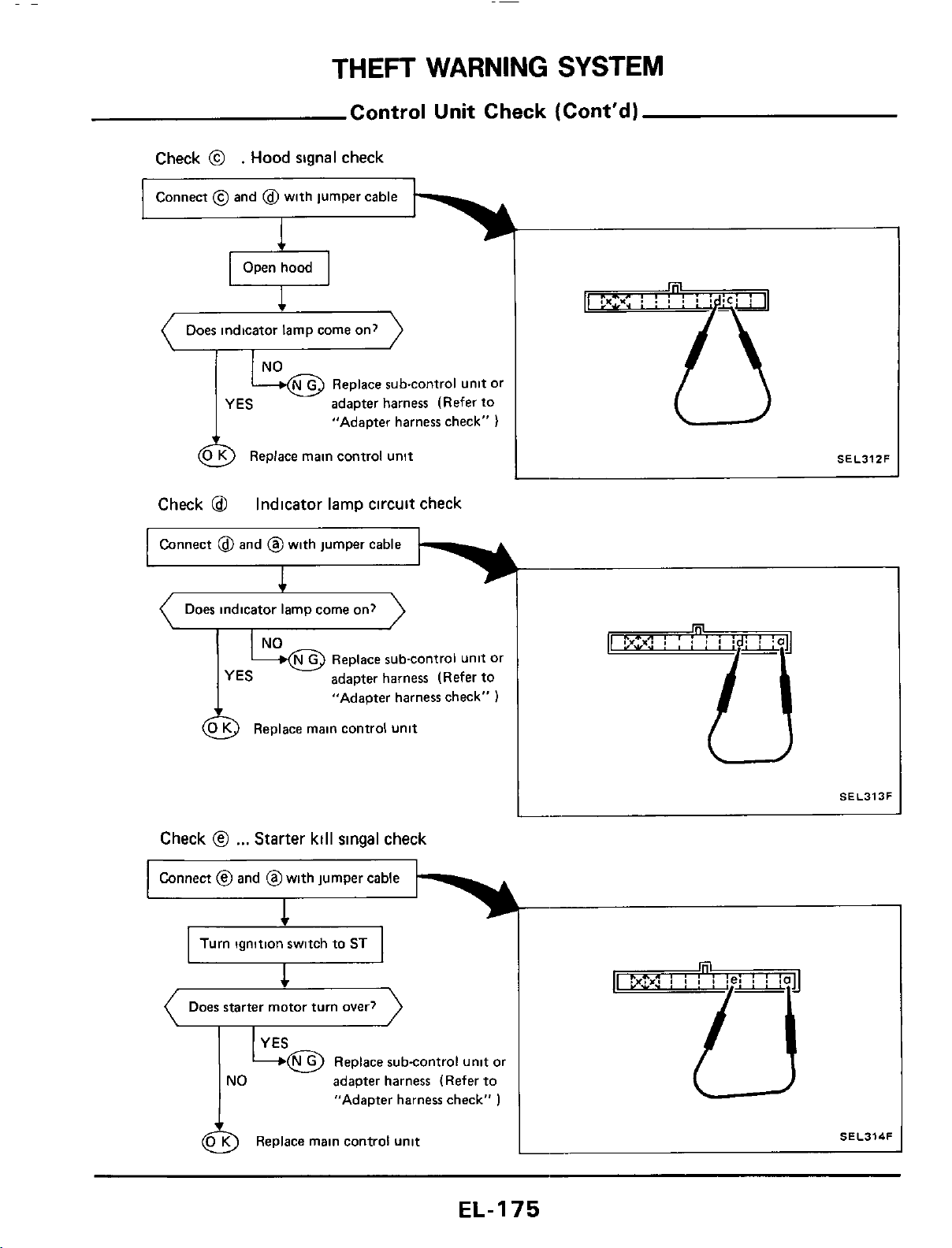
THEFT
WARNING
SYSTEM
Control Unit Check (Cont'd)
Check
@
.
Hood
signal check
Connect
@
and
@
with jumper cable
1
Does indicator lamp come on?
Replace sub-control unit or
adapter harness (Refer to
"AdaDter harness check"
)
YES
SEL31ZF
L
&
Replace main control unit
Check
@
Connect
@
and @with jumper cable
Indicator lamp circuit check
1
)
(
Does indicator lamp come on?
SEL313F
I
Check
@
...
Starter kill
singal
check
Connect
@
and @with jumper cable
Does starter motor turn over?
adapter harness (Refer to
"Adapter harness check"
)
SEL314F
L
@
Replace main control unit
EL-I
75
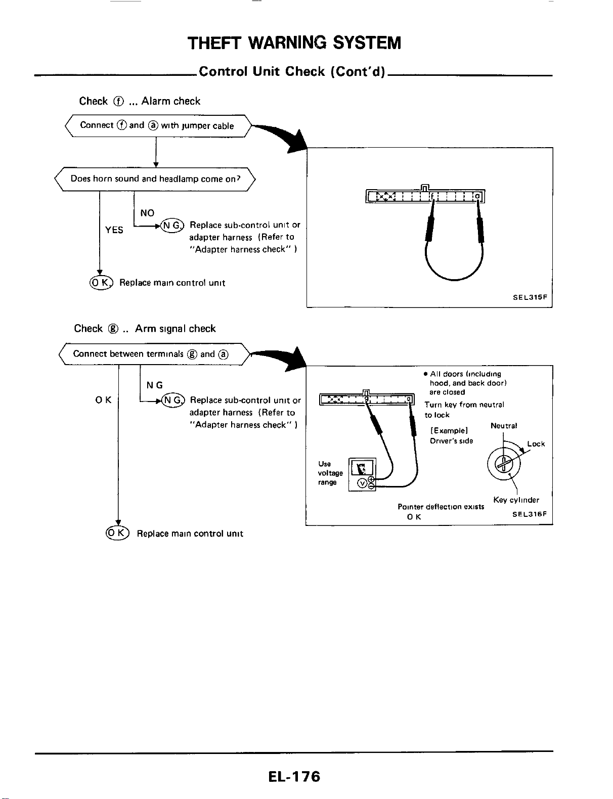
THEFT
WARNING
SYSTEM
Control
Unit
Check (Cont'd)
Check
@I
...
Alarm
check
Connect @and @with jumper cable
Does horn sound and headlarnp come on?
Replace sub-control unit
or
adapter harness (Refer to
YES
"Adapter harness check"
)
Replace main control unit
Check
@
..
Arm
signal
check
Connect between terminals @and
@
adapter harness (Refer
to
"Adapter harness check"
1
)
Replace main control
unit
W
SEL315F
n
voltage
range
0
All
doors
lincluding
hood, and
back
door1
are
closed
Turn
key from neutral
to
lack
Neutral
[Example1
Key ehnder
Pomer deflection
exists
OK
SEL316F
EL-I
76
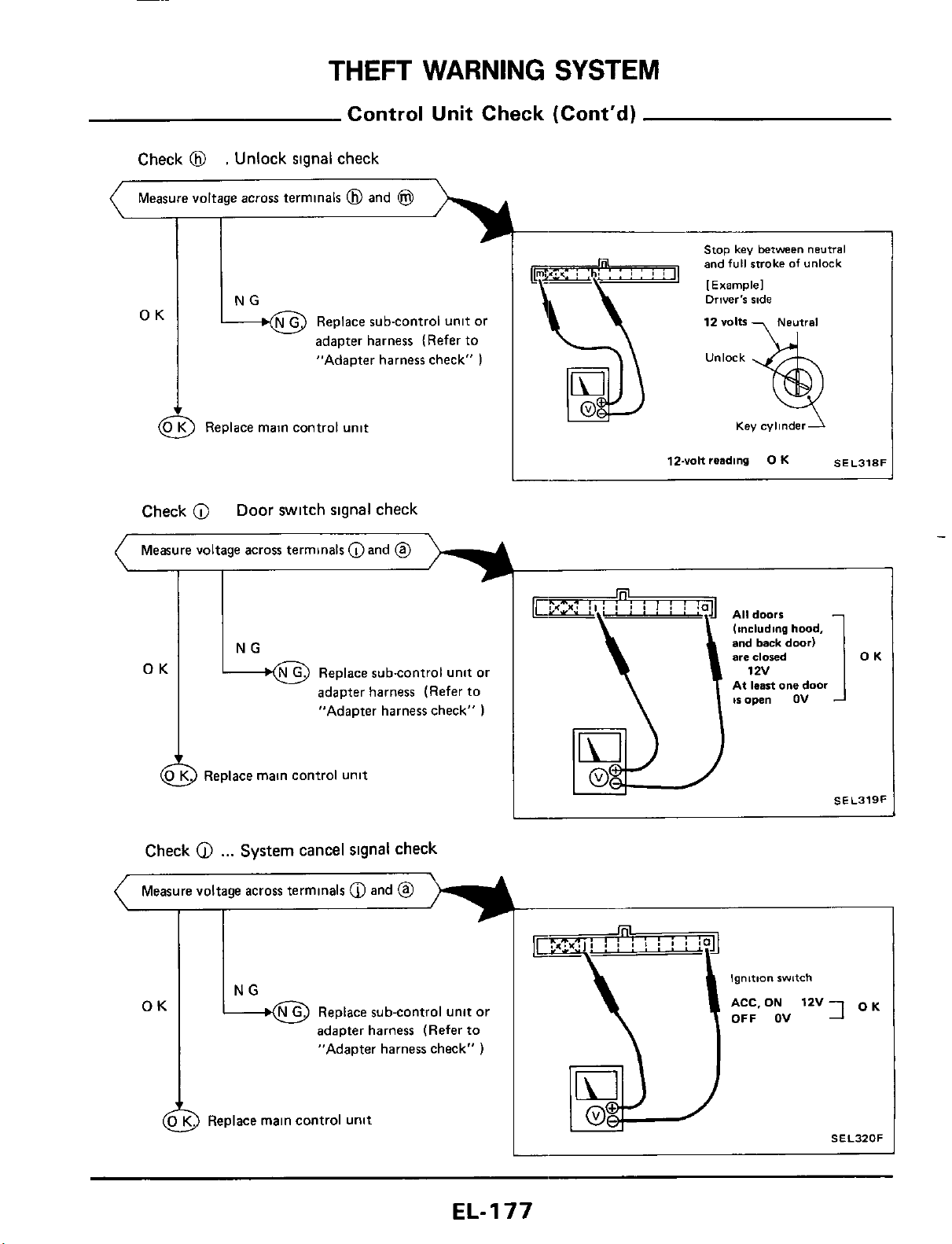
Stop
key
between
neutral
and
full
stroke
of
unlock
[
Example1
12
volts
Neutral
NG Driver's ride
Measure voltage across terminals
@
and
@
I I
OK
OK
N G
Replace sub-control unit or
*
adapter harness (Refer to
"Adapter harness check"
)
Replace sub-control unit or
adapter harness (Refer to
"Adapter harness check"
)
(4
0
K
Replace main control unit
Check
@
...
System
cancel
signal
check
Measure voltage across terminals
@
and
@
OK
&
Replace subcontrol unit or
adapter harness (Refer to
"Adapter harness check"
)
a
Replace main control unit
Ignition
switch
ACC.
ON
12v7
OK
OFF OV
SEL320F
EL-I
77
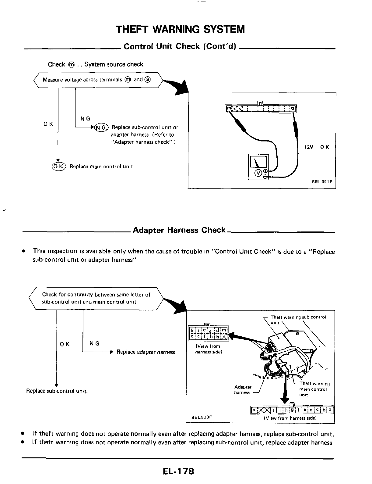
THEFT
WARNING
SYSTEM
Control Unit Check (Cont'd)
OK
Check
@
. .
System source check
NG
(
Measure voltage across terminals
@
and
@
-----%
L
OK
G
Replace sub-control unit
01
adapter harness (Refer to
"Adapter harness check"
1
)
Replace main control unit
SELJZlF
Adapter Harness Check
This inspection
is
available only when the cause of trouble in "Control Unit Check"
is
due to
a
"Replace
sub-control unit or adapter harness"
If
theft warning does not operate normally even after replacing adapter harness, replace sub-control unit.
If theft warning does not operate normally even
after
replacing sub-control unit, replace adapter harness
EL-
1
7%
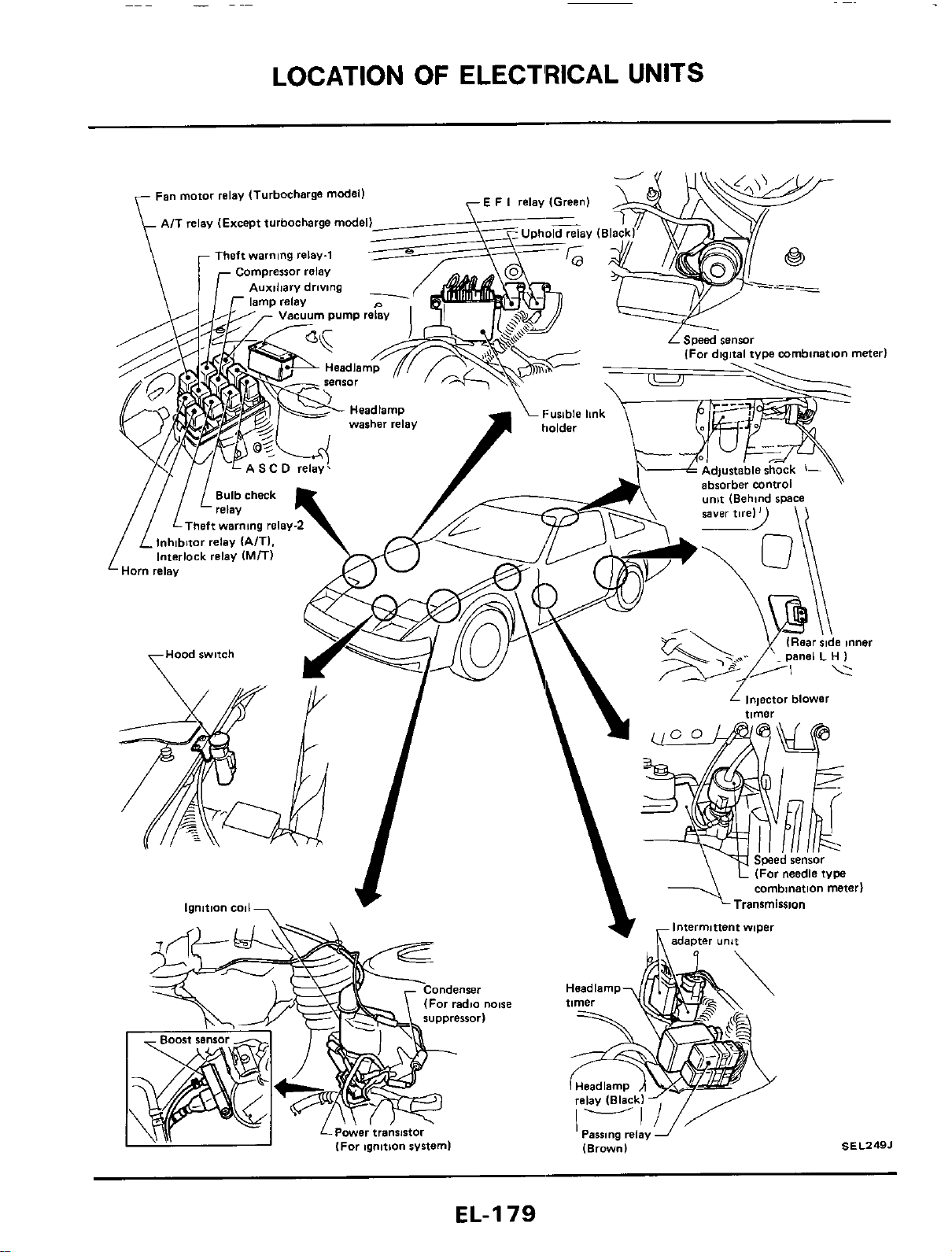
LOCATION
OF
ELECT'RICAL UNITS
EL-I
79
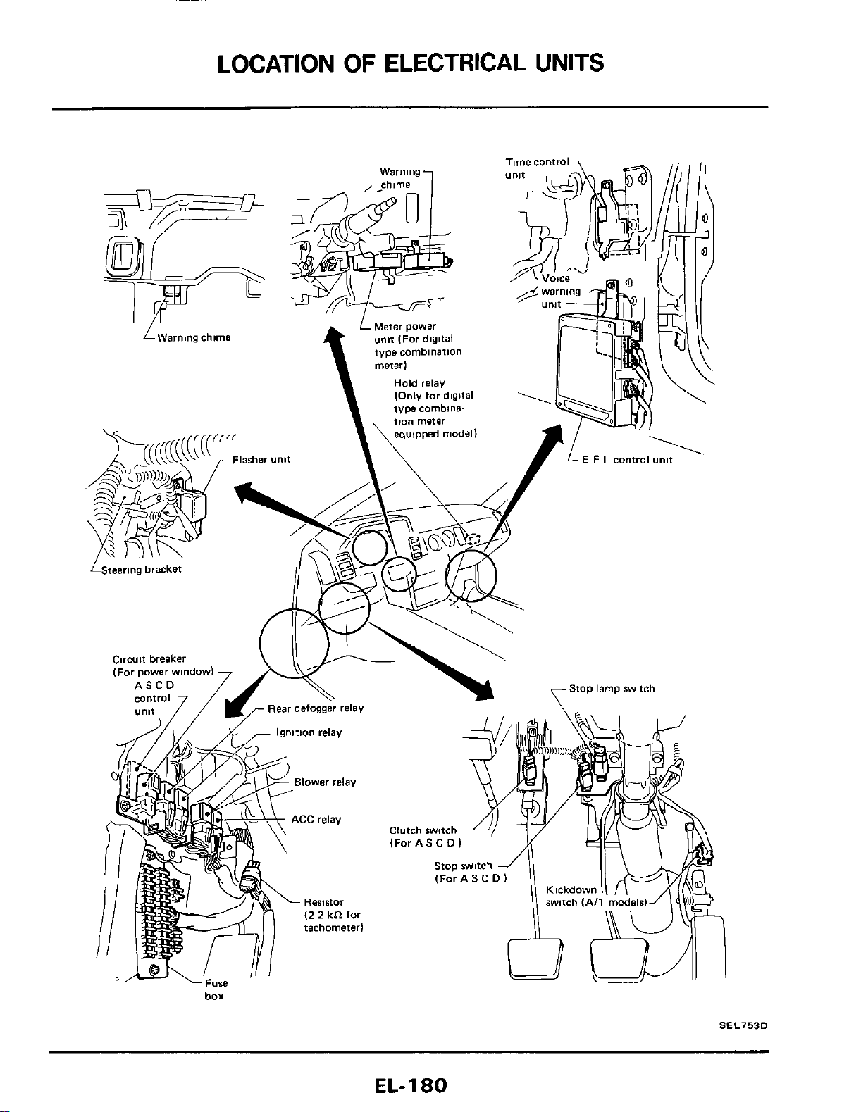
LOCATION
OF
ELECTRICAL
UNITS
box
SEL753D
EL-I
80
HARNESS
LAYOUT
Note
EL-I
81
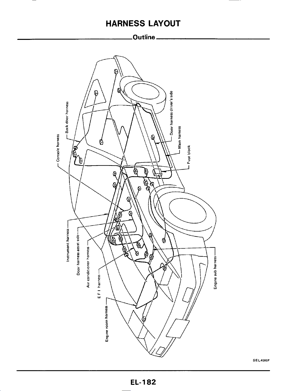
HARNESS
LAYOUT
SEL496F
EL-
1
82
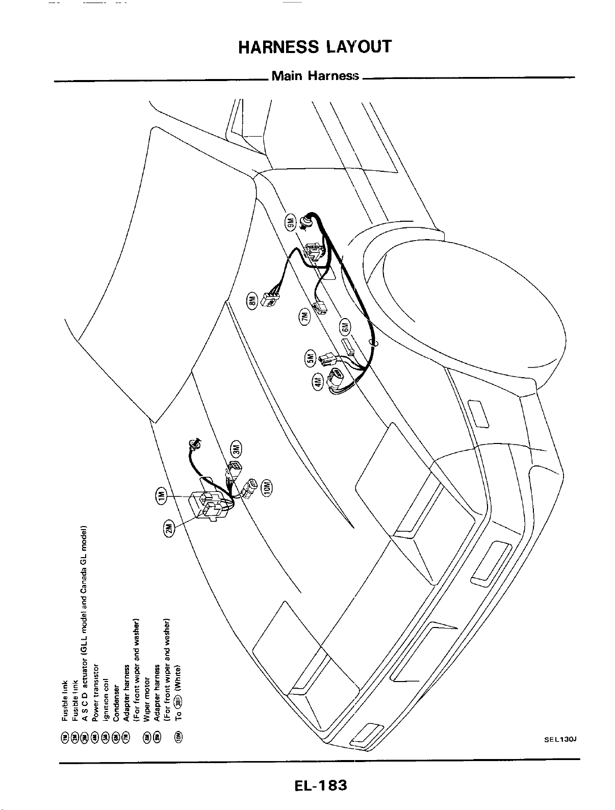
HARNESS
LAYOUT
Main
Harness
EL-I
83
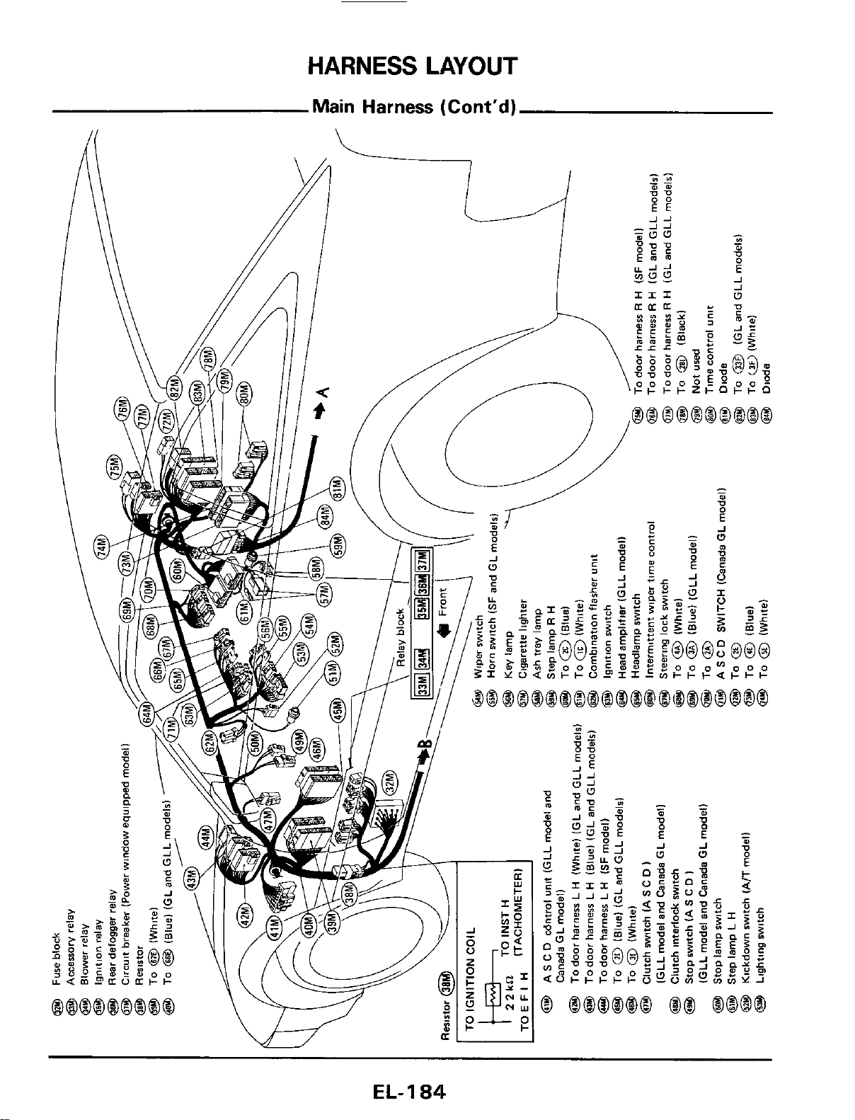
HARNESS
LAYOUT
EL-
1
84
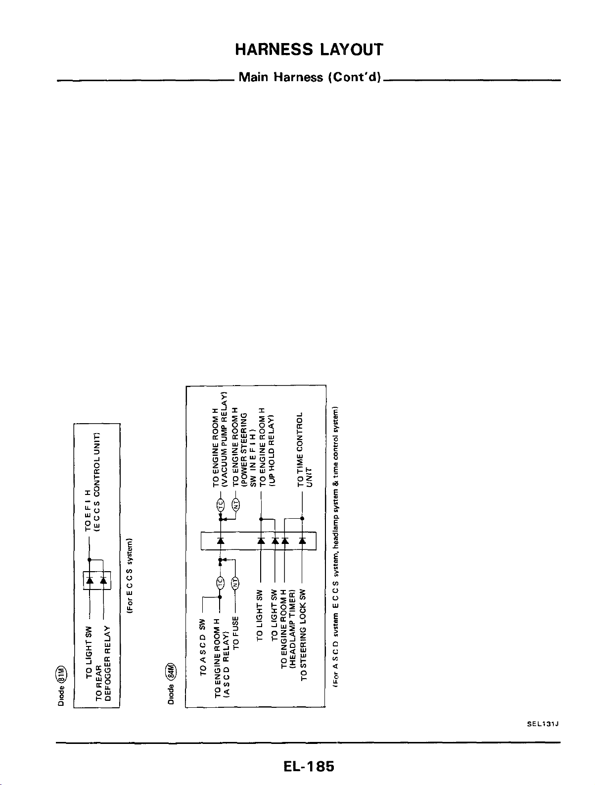
HARNESS
LAYOUT
Main Harness (Cont'd)
SEL131J
EL-
I
a5
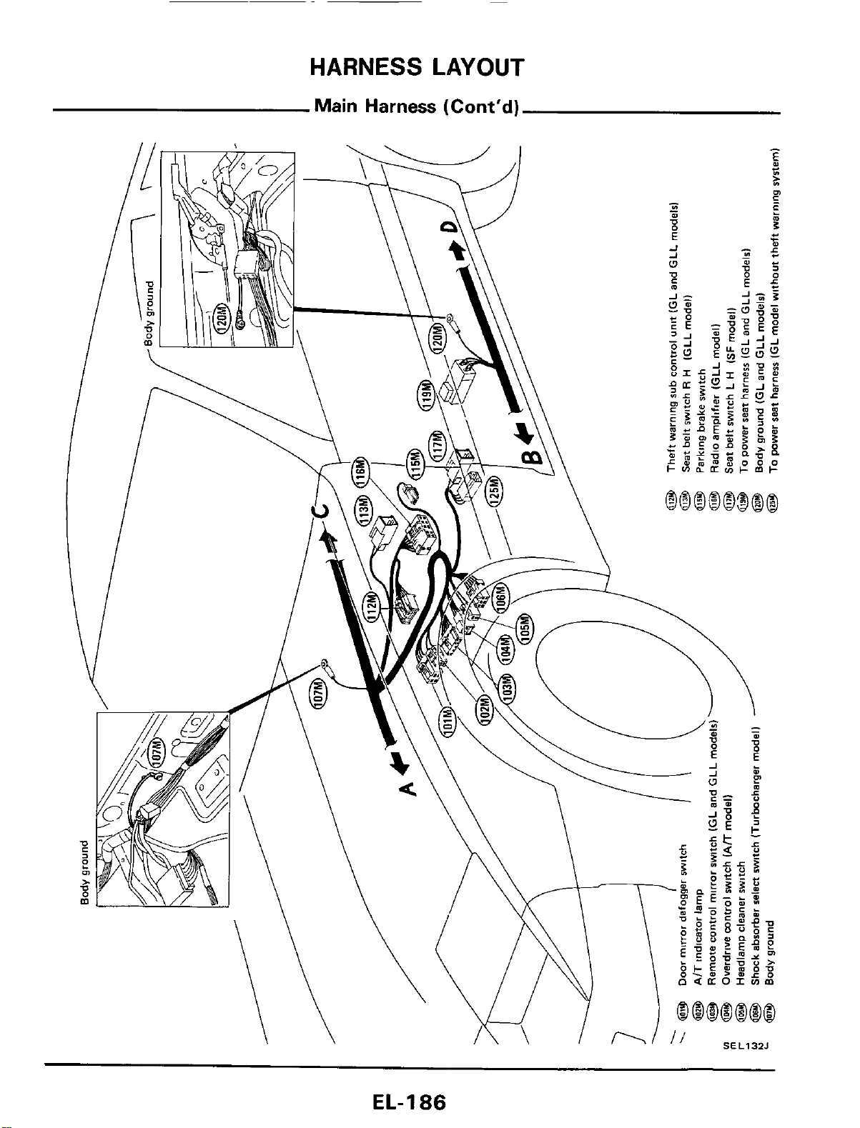
HARNESS
LAYOUT
Main
Harness
(Cont'd)
EL-
1
86
HARNESS
LAYOUT
Note:
EL-187
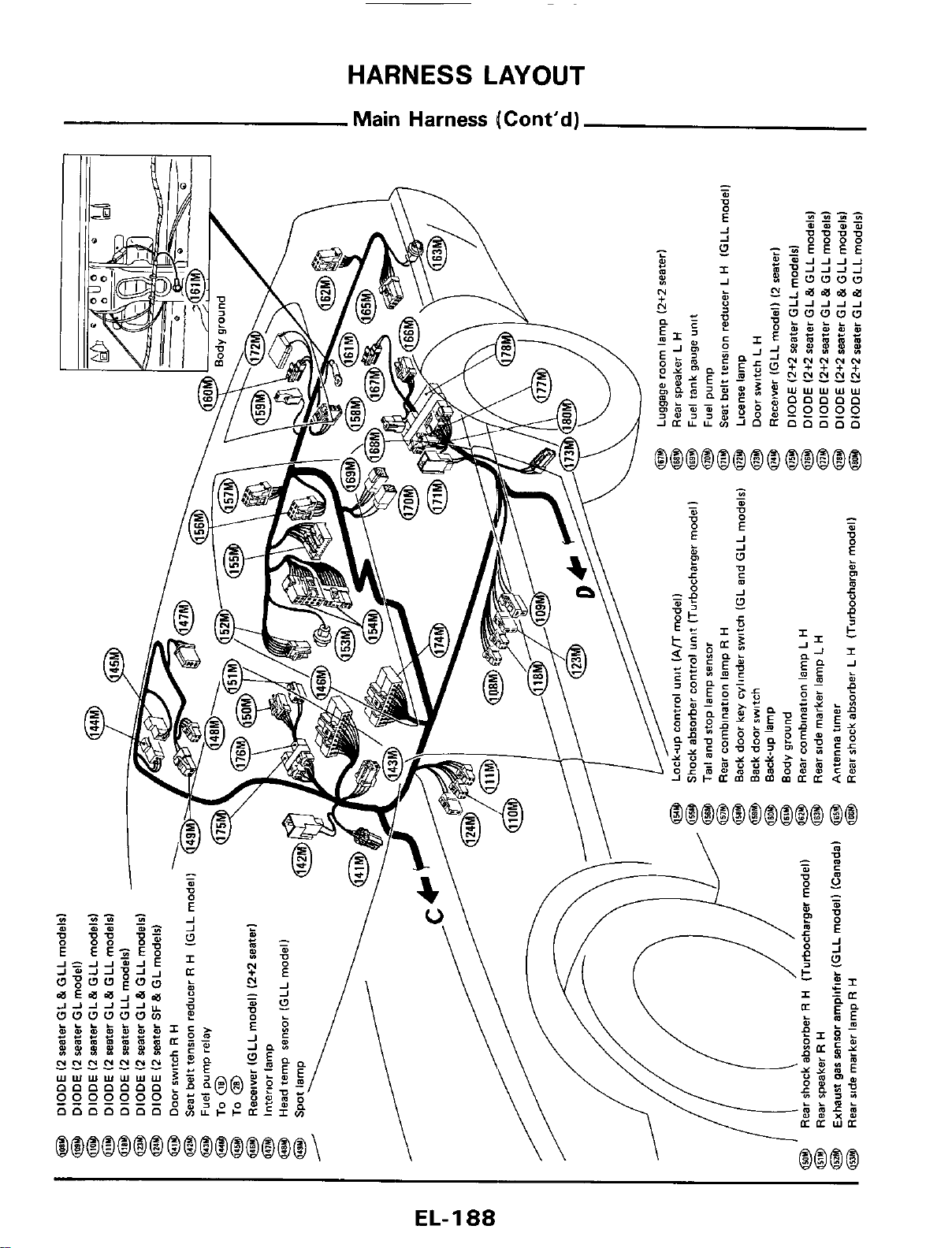
HARNESS
LAYOUT
Main
Harness
(Cont’d)
EL-I
88
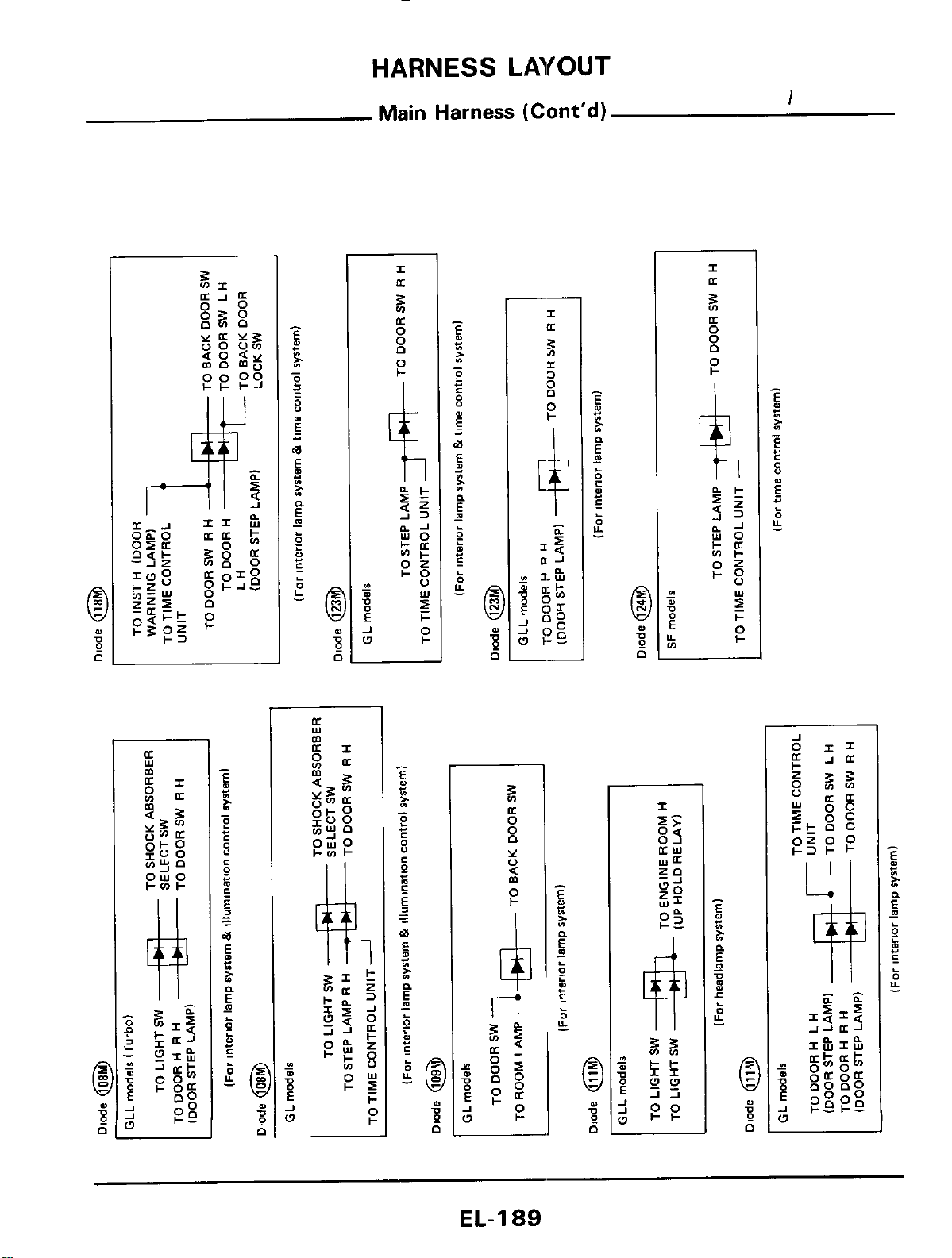
HARNESS
LAYOUT
Main
Harness
(Cont'd)
I
C
A
w
k
5
8
4,
P
a:
0
Y
0
(Y
0
P
n
EL-189
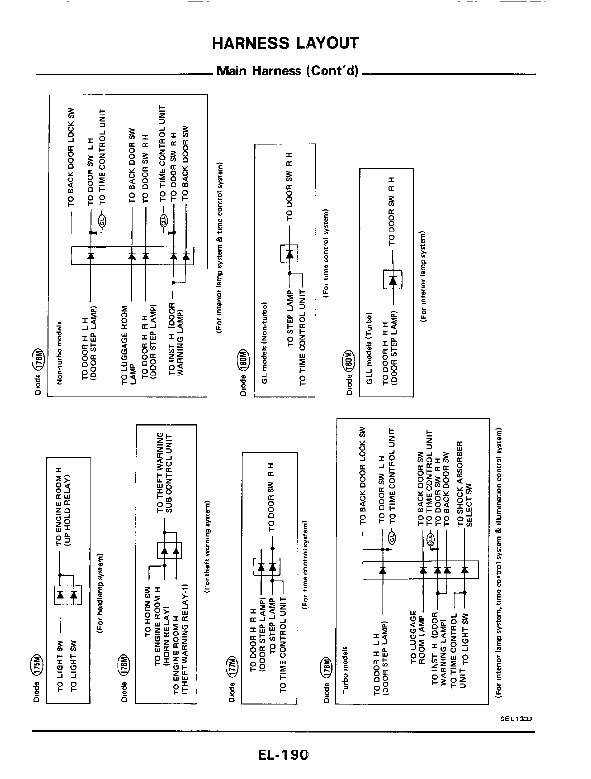
HARNESS
LAYOUT
Main
Harness
(Cont'd)
EL-
1
901
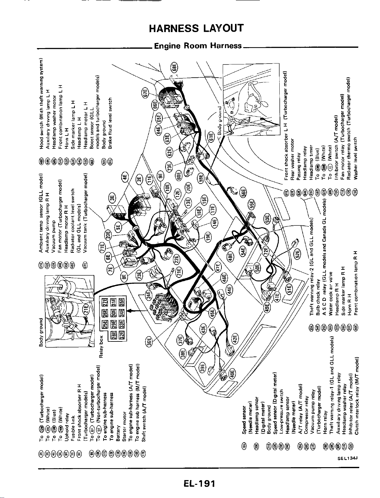
HARNESS
LAYOUT
Engine Room
Harness
EL-191
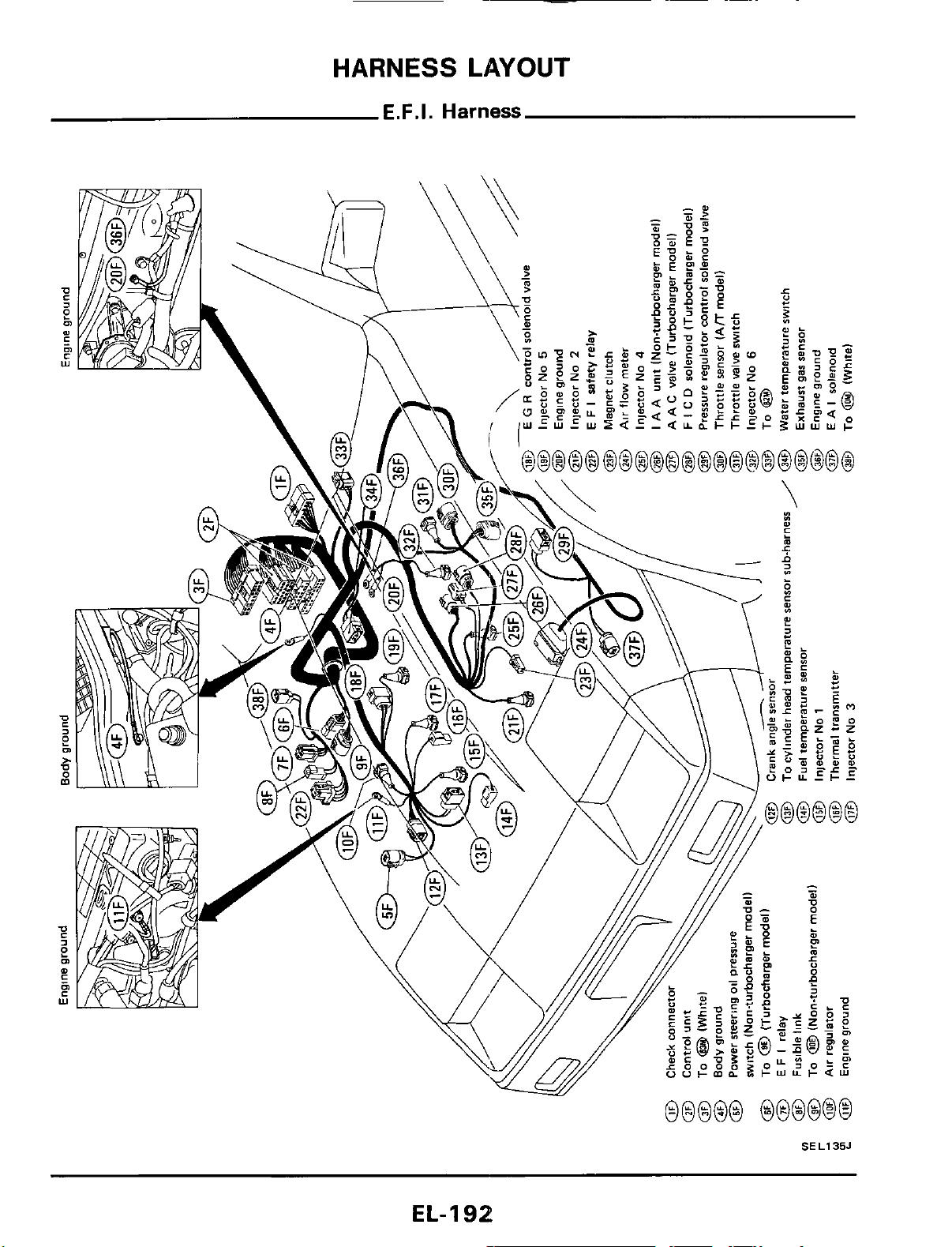
HARNESS
LAYOUT
E.F.I.
Harness
SEL135J
EL-192
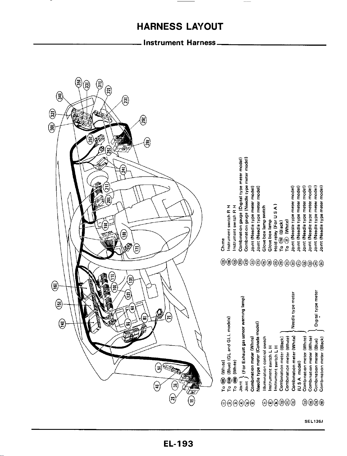
HARNESS
LAYOUT
Instrument
Harness
SEL136J
EL-I
93
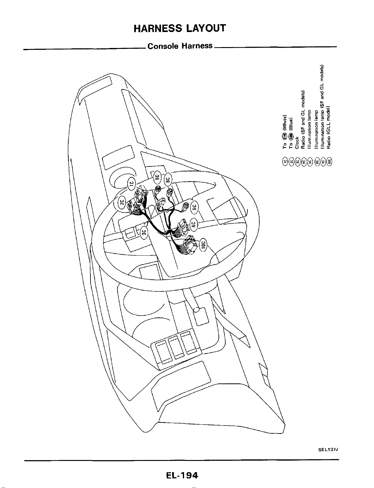
SEL137J
EL-
1
94
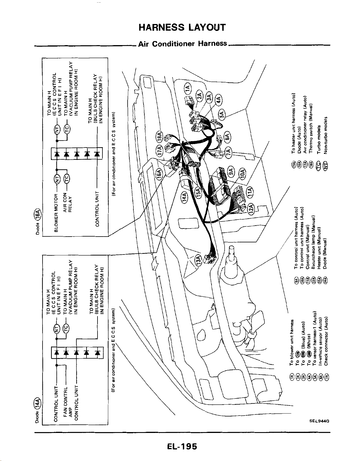
HARNESS
LAYOUT
Air Conditioner Harness
SEL944G
\
EL-195
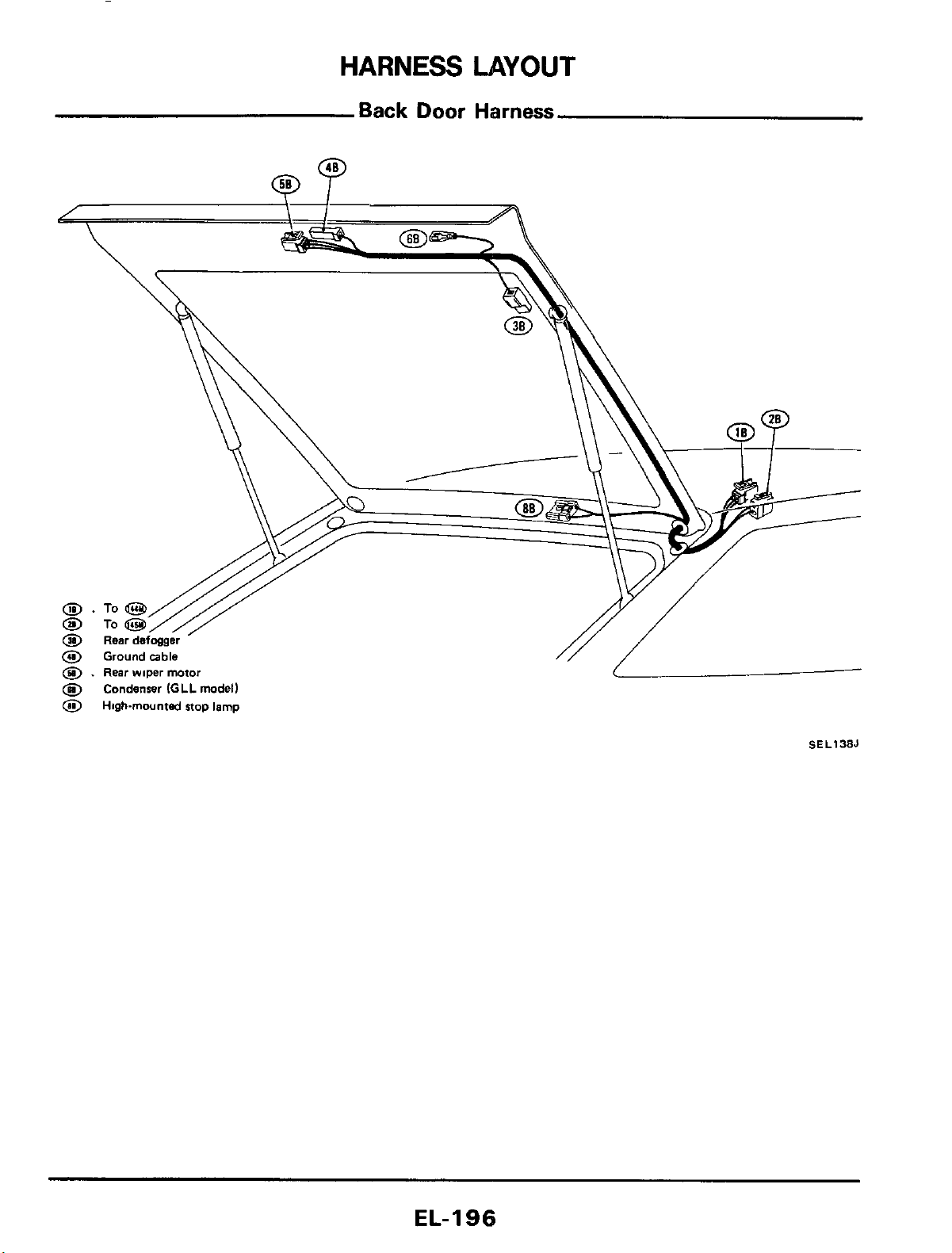
HARNESS
LAYOUT
Back
Door
Harness
@
Condenser
IGLL
model)
0
Highmounted
stop lamp
SEL138J
EL-I
96
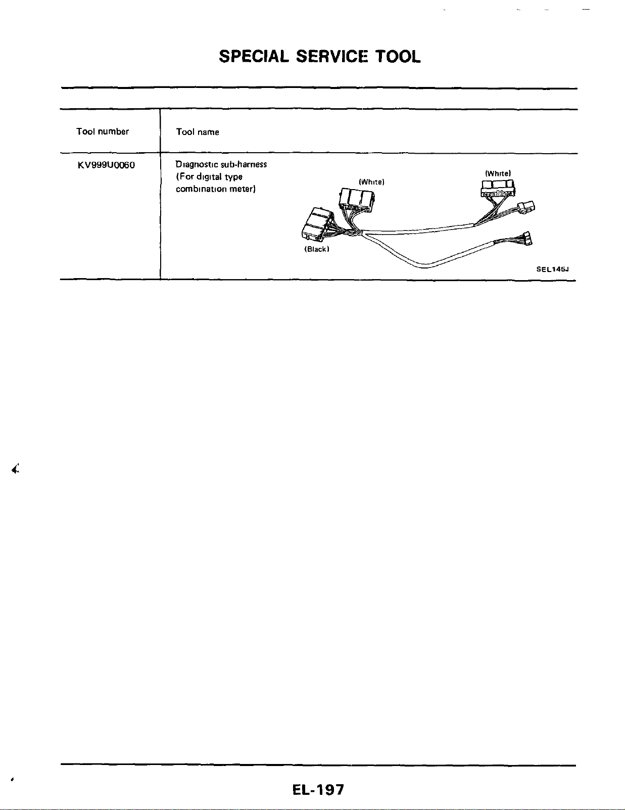
SPECIAL SERVICE: TOOL
Tool
number
Tool
name
KV999U0060
,
Diagnostic sub-harness
(For digltal type
combination meter)
IWhitel
SEL145J
EL-197

Courtesy Nissan
1777 North Central Expressway
Richardson, TX 75080
(800)527-1909
N
ISSAN FACTORY SERVICE MANUAL CDROM END-USER LICENSE AGREEMENT
NOTICE TO USER: THIS IS A CONTRACT. BY PURCHASING AND USING THE SERVICE MANUAL ON
CDROM, YOU ACCEPT ALL THE TERMS AND CONDITIONS OF THIS AGREEMENT.
This End User License Agreement accompanies the Service Manual on CDROM product and related explanatory
materials. Please read this Agreement carefully. By purchasing and using the Service Manual on CDROM, you are
implying that you have carefully read, agree with, and will adhere to the conditions set forth in this agreement. If
you do not wish to accept the terms of this End User Agreement please do not use the Service Manual on CDROM.
You will not be permitted to use the Service Manual on CDROM without consenting to this end user agreement.
Upon your acceptance of this Agreement, Courtesy Nissan grants to you a nonexclusive license to use the Service
Manual on CDROM, provided that you agree to the following:
U
SE OF SOFTWARE
You may install the contents of the CD on a hard disk or other storage device for personal use only. Each Service
Manual on CDROM comes with a single user license. Under no circumstances should the contents of the Service
Manual CDROM be placed on a server for purposes of distributing or allowing access to the material over a
network.
C
OPYRIGHT AND TRADEMARK RIGHTS
The Service Manual CDROM is owned by Courtesy Nissan and its structure and organization, all graphics and
coding are considered intellectual property of Courtesy Nissan. The Service Manual on CDROM is also protected by
United States Copyright Law and International Treaty provisions. This Agreement does not grant you any
intellectual property or resale rights to the Service Manual CDROM.
R
ESTRICTIONS
You agree not to modify, adapt, translate, reverse engineer, decompile or disassemble the PDF file on the Service
Manual CDROM. The Service Manual on CDROM is licensed and distributed by Courtesy Nissan for single user
utilization of its contents only. Licensed users will be permitted to use the contents of the Service Manual CDROM
for multimedia presentation to an audience from a single machine using a large display or projection device but the
Service Manual CDROM may not otherwise be distributed, sold to or made accessible to multiple users.
N
O WARRANTY
The software is being delivered to you AS IS and Courtesy Nissan makes no warranty as to its use or performance.
COURTESY NISSAN DOES NOT AND CANNOT WARRANT THE PERFORMANCE OR RESULTS YOU
MAY OBTAIN BY USING THE SERVICE MANUAL CDROM OR DOCUMENTATION, NOR MAKES ANY
WARRANTIES, EXPRESS OR IMPLIED, AS TO NONINFRINGEMENT OF THIRD-PARTY RIGHTS,
MERCHANTABILITY, OR FITNESS FOR ANY PARTICULAR PURPOSE. IN NO EVENT WILL COURTESY
NISSAN BE LIABLE TO YOU FOR ANY CONSEQUENTIAL, INCIDENTAL, OR SPECIAL DAMAGES FOR
ANY REASON.

Courtesy Nissan
1777 North Central Expressway
Richardson, TX 75080
(800)527-1909
G
OVERNING LAW AND GENERAL PROVISIONS
This Agreement will be governed by the laws of the State of Texas, USA, excluding the application of its conflicts
of law rules. This Agreement will not be governed by the United Nations Convention on Contracts for the
International Sale of Goods, the application of which is expressly excluded. If any part of this Agreement is found
void and unenforceable, it will not affect the validity of the balance of the Agreement, which shall remain valid and
enforceable according to its terms. You agree that the Service Manual on CDROM will not be shipped, transferred
or exported into any country or used in any manner prohibited by the United States Export Administration act or any
other export laws, restrictions or regulations. This Agreement shall automatically terminate upon failure by you to
comply with its terms. This Agreement may only be modified in writing signed by and authorized officer for
Courtesy Nissan.
Courtesy Nissan
1777 North Central Expressway
Richardson, TX 75080
USA
YOUR ACCEPTANCE OF THE FOREGOING AGREEMENT IS IMPLIED UPON PURCHASING AND USING
THE SERVICE MANUAL CDROM.