Loading ...
Loading ...
Loading ...
CD-C1H/CP-C1H
– 14 –
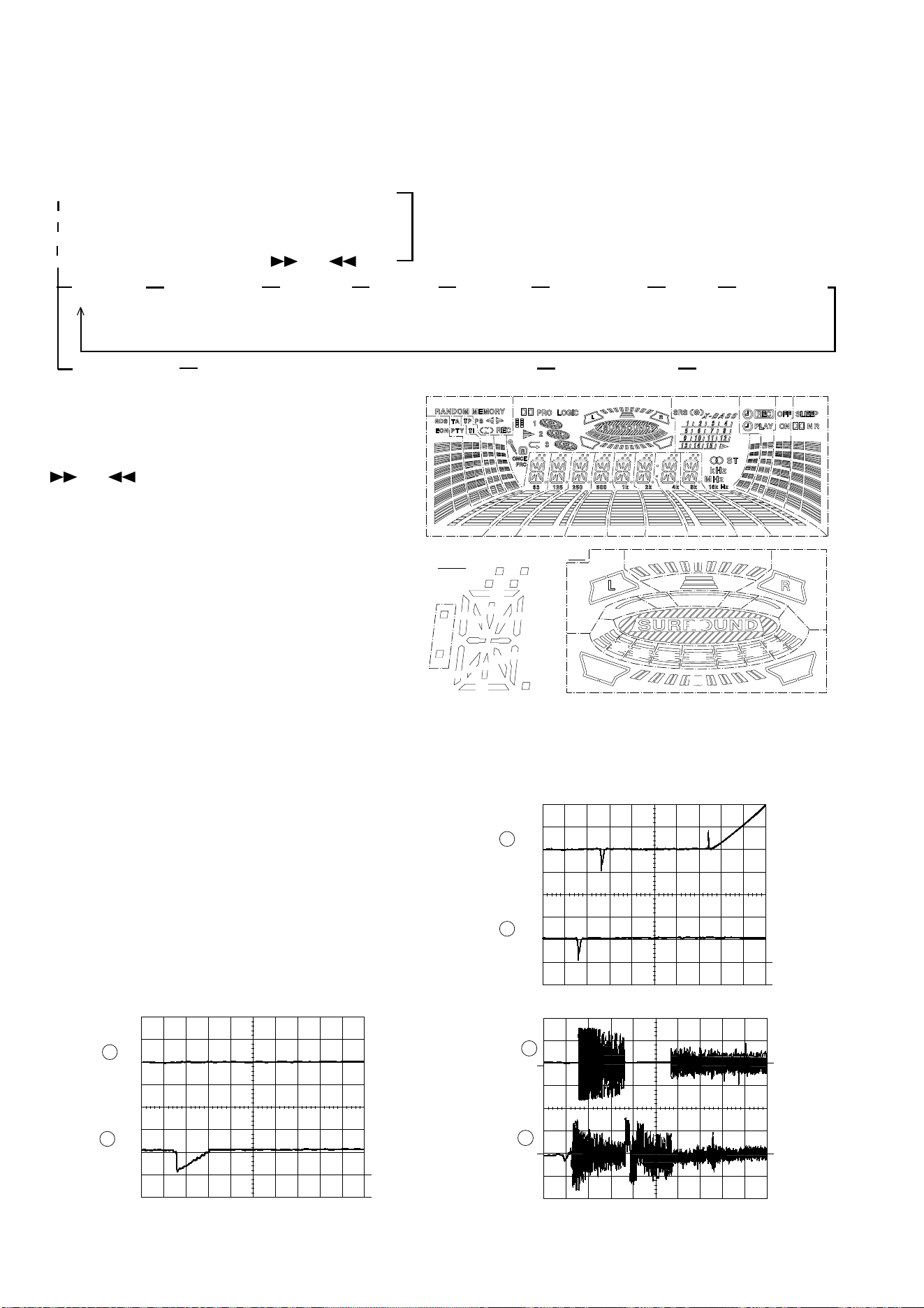
Figure 14-2
Figure 14-3
Since this CD system incorporates the following automatic adjustment function, when the pickup is replaced, it is not necessary
to readjust it.
Since this CD unit does not need adjustment, the combination of PWB and laser pickup unit is not restricted.
• Automatic adjustment item
1. Focus offset (Fig. 14-2)
2. Tracking offset (Fig. 14-3)
3. E/F balance (tracking error balance) (Fig. 14-4)
4. RF level AGC function (HF level: constant)
5. RF level automatic follow-up of the tracking gain
This automatic adjustment is performed each time a disc is changed.
Therefore, each disc is played back using the optimal settings.
CD SECTION
TEST MODE
• Setting the test mode
Any one of test mode can be set by pressing several keys as follows.
Hold down the EQ and CD buttons, and press the POWER switch. TEST: CD operation test
<PLAY> key input
• TEST mode
Function — CD test mode
Setting of TEST mode
Indication of CD TEST mode (Fig. 14-1)
OPEN/CLOSE operation is manual operation.
The pickup can be moved by using the (
) or ( ) key.
When the track-
ing servo is acti-
vated, playback
will begin at the
current position.
Press the
STOP button.
The pickup
willreturn to
the STOP
position.
<MEMORY>
key input
When the track-
ing servo is acti-
vated, playback
will begin at the
current position.
<STOP>
key input
The pickup nor-
mally returns to
the STOP posi-
tion.
<MEMORY>
key input
IL is not performed.
Press <STOP> key. Stop
TOC. IL is performed, and the ordinary PLAY is performed.
If the following key is pressed during PLAY, it is possible
to specify directly any Track No.
<Disc Number 1> key: Track 4
<Disc Number 2> key: Track 9
<Disc Number 3> key: Track 15
Note:
Only in STOP state it is possible to slide the pickup with the
(
) or ( ) key.
VOL. --- Last memory
BAL. --- CENTER
R.GEQ. --- FLAT
X-BAS --- OFF
Canceling method - POWER OFF
Figure 14-1
G9 G9
G9
G6
G6
G8
G8
G5
G5
G4
G4
G10
G3
G10
G3
G2
G2
G1
G1~G8
G7
G7
S40
S39
S38
S30
S33
S35
S37
S36
S34
S31
S29
S27
S25
S23
S32
S24
S26
S28
S22
S41
S10
S1
S2
S7
S6
S5
S4
S3
S9 S8
S16
S15
S14
S13
S12
S17
S19
S21
S20
S18
2
0.1s
0.50 V
IC1 16 FD
FOCUS
OFF-SET
ADJUST
TRACKING
OFF-SET
ADJUST
0.1s
0.50 V
IC1 7 TE
1
2
1
10ms
0.50 V
IC1 16 FD
10ms
0.50 V
IC1 7 TE
Enlarged
View
TRACKING
OFF-SET
ADJUST
2
1
TO
TE
200 ms
1V/diV
IC 1 15
200 ms
1V/diV
IC 1 7
TRACKING/
ERROR
BARANCE
ADJUST
Figure 14-4
Loading ...
Loading ...
Loading ...