Loading ...
Loading ...
Loading ...
CD-C1H/CP-C1H
– 10 –
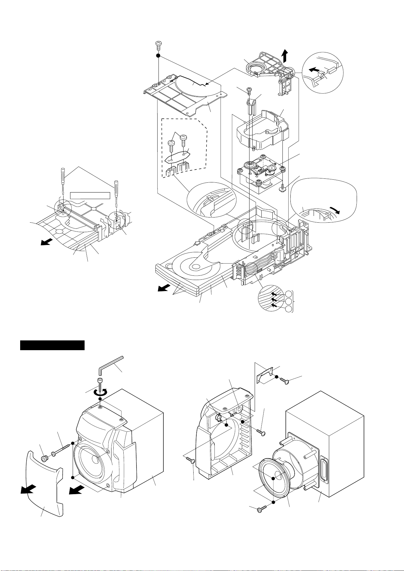
Figure 10-1
Figure 10-2 Figure 10-3
CP-C1H
Push the pawl of disc tray
with a proper screwdriver.
Back surface
Pawl
Disc Tray 1
Disc Tray 2
Disc Tray 3
Pawl
(After drawing out the disc trays 1, 2, and 3, turn
over the mechanism unit, push two pawls, and
remove successively the three disc trays from the
mechanism unit, starting with the disc tray 3.
Thereby the CD mechanism shown in the right
figure can be removed.)
(S1) x2
ø2 x7mm
(S5) x1
ø2.6 x12mm
(S10) x4
ø2.6 x10mm
(S3) x1
(S2) x1
(S6) x1
(S9) x1
Disc Tray 2
Disc Tray 3
Spring
(S4) x3
1
2
3
Normal state
Press in turns the arrow
parts, starting with the
uppermost one, to
withdraw the disc trays
Pawl
Push
.
CD
Mechanism
Disc Tray 1
Turn clockwise the
main cam to raise the
CD mechanism up to
the uppermost position.
(S7) x2
ø2 x6mm
(S8) x1
(A4)x2
ø4x20mm
(A3)x4
ø4x25mm
(A2)x4
(A1)x1
Front Panel
Driver
Speaker
Box
(B5)x4
ø4x12mm
(B1)x2
ø3x10mm
(B4)x2
ø3x10mm
(B2)x2
ø3x10mm
Front
Panel
Speaker
Box
Super
Tweeter
Tweeter
(B3)x1
Woofer
Loading ...
Loading ...
Loading ...