
www.lg.com
Copyright 2019 LG Electronics Inc. All Rights Reserved.
Please read this manual carefully before operating your set and retain it
for future reference.
27HK510S
OWNER’S MANUAL
MEDICAL MONITOR

2
ENGLISH
CONTENTS
LICENSE ...................................................2
OPEN SOURCE SOFTWARE
NOTICE INFORMATION .............................2
ASSEMBLY AND PREPARING ....................3
USER SETTINGS .....................................13
TROUBLESHOOTING ..............................32
PRODUCT SPECIFICATIONS ....................34
EXTERNAL CONTROLLER SETUP ............39
LICENSE
Each model has different licenses. Visit
www.lg.com
for more information on the license.
The terms HDMI and HDMI High-Definition Multimedia Interface,
and the HDMI Logo are trademarks or registered trademarks of
HDMI Licensing Administrator, Inc. in the United States and other
countries.
The SuperSpeed USB Trident logo is a registered trademark of USB
Implementers Forum, Inc.
OPEN SOURCE SOFTWARE NOTICE
INFORMATION
To obtain the source code under GPL, LGPL, MPL, and other open source licenses, that is contained in this product,
please visit
http://opensource.lge.com.
In addition to the source code, all referred license terms, warranty disclaimers and copyright notices are available
for download.
LG Electronics will also provide open source code to you on CD-ROM for a charge covering the cost of performing
such distribution (such as the cost of media, shipping, and handling) upon email request to
This offer is valid for a period of three years after our last shipment of this product. This offer is valid to anyone in
receipt of this information.
3
ENGLISH
ASSEMBLY AND PREPARING
Product Composition
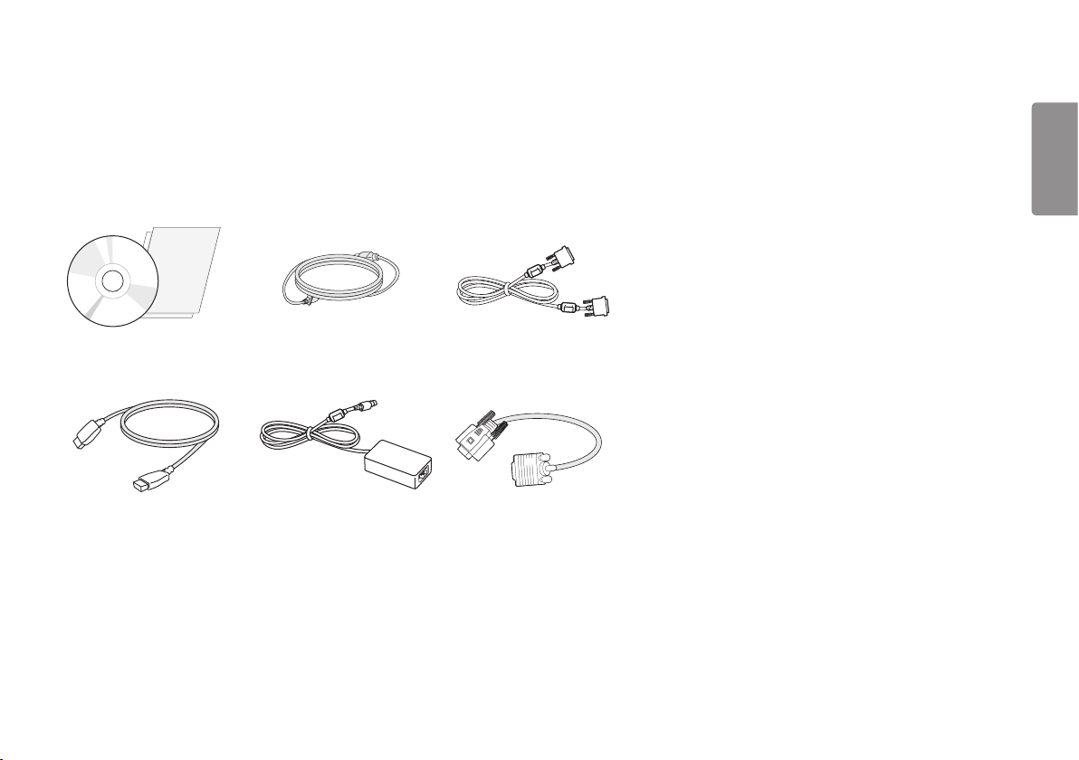
Please check whether all the components are included in the box before using the product. If there are any missing components, contact the retailer where you purchased the product.
Note that the product and related components may look different from those shown here.
CD (Software/Owner's Manual)/Regulatory
Manual/Cards
Power Cord DVI Cable
HDMI Cable
AC/DC Adaptor DVI-I to D-SUB Gender Cable
4
ENGLISH
CAUTION
• Always use genuine LG components to ensure safety and product performance.
• The product warranty will not cover damage or injury caused by the use of unauthorized components.
• It is recommend that use the supplied components.
• If you use generic cables not certified by LG, the screen may not display or there may be image noises.
• Need to use the authorized components about the below accessories. Unauthorized components may be cause
of the damage and malfunction of the product.
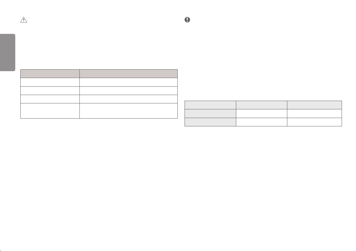
Component Standard
HDMI Cable UL, Impedance 100ohm
DVI Cable UL, Impedance 100ohm
DVI-I to D-SUB Gender Cable UL, Impedance 75ohm
Power Cord US – Approved Medical grade regulation
Others – Approved country safety regulation
• The AC/DC adaptors and etc. except the upper components need to be used only supplied by manufacturer.
NOTE
• The components may look different from those illustrated here.
• Without prior notice, all product information and specifications contained in this manual are subject to change
to improve the performance of the product.
• To purchase optional accessories, visit an electronics store or an online shopping site, or contact the retailer
from which you purchased the product.
• The power cord provided may differ depending upon the region.
Supported Drivers and Software
Check the drivers and software supported by your product and refer to the manuals on the CD enclosed in the
product package.
Drivers and Software Installation Priority 27HK510S
Monitor Driver Recommended O
True Color Pro Optional O
• Required and Recommended: You can download and install the latest version from the enclosed CD or from the
LGE website (
www.lg.com
).
• Optional: You can download and install the latest version from the LGE website (
www.lg.com
).
5
ENGLISH
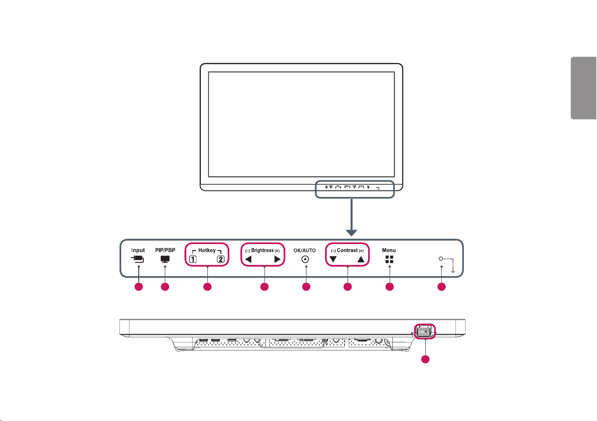
Product and LED Control buttons
9
1 2 5 7 8 3 6 4
6
ENGLISH
LED Control button Functions
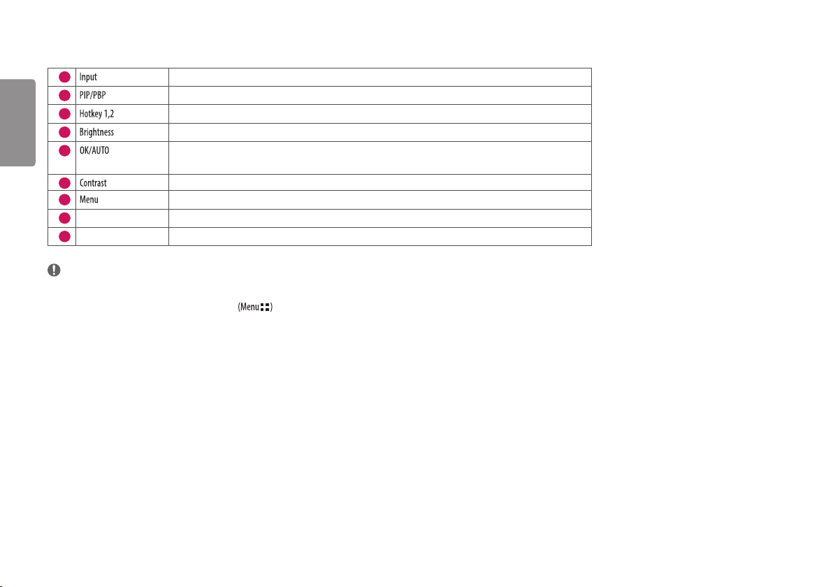
1
Selects the input mode.
2
Displays the screens of two input modes on one monitor.
3
Opens the [Hot key Settings] menu.
4
Adjusts the screen brightness.
5
Selects and confirms menus or options
* Automatically sets screen to optimal settings in analog video signal.
6
Adjusts the screen contrast.
7
Displays LED Control buttons on the front panel and opens the menu mode.
8
Power indicator The green indicator illuminates if the power is on. The arrow indicates the position of the power switch.
9
Power switch Turns the power on/off.
NOTE
• The Power button is located at the bottom right on the front of the monitor.
• If the Control Key LED is turned off, press the Control Key button to turn the Control button LED on. When the Control Key LED is turned on, you can control the Control Key functions.
7
ENGLISH
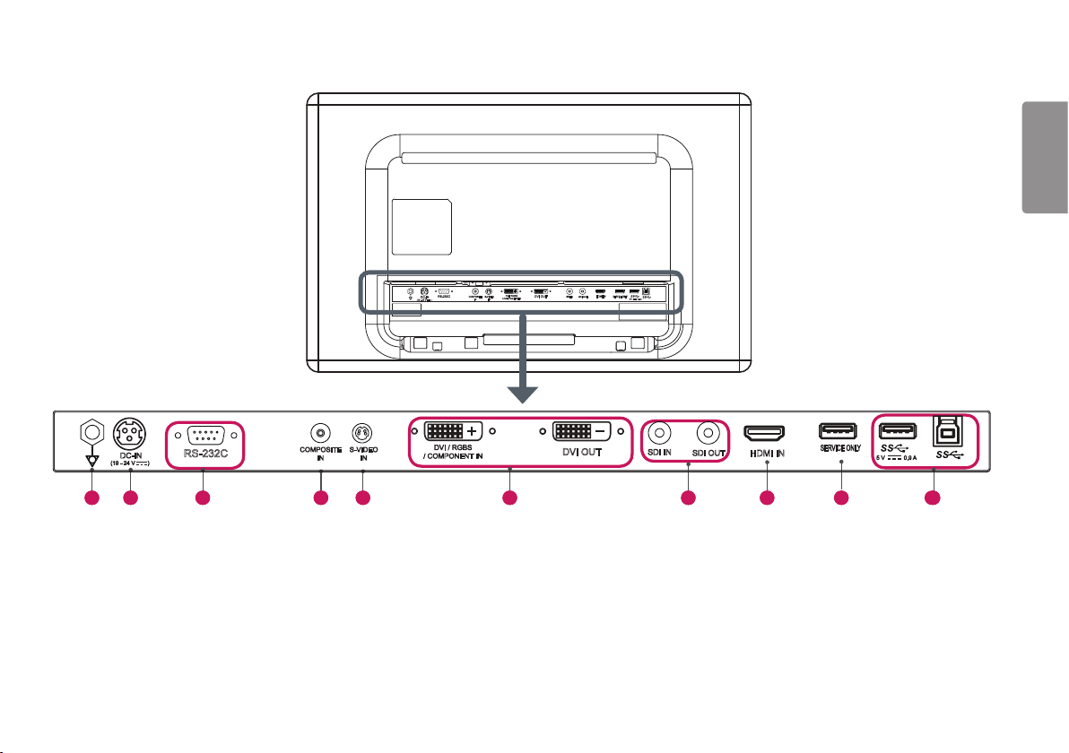
Connectors
1 2 3 4 5 6 7 9 8 10
RS-232C COMPOSITE
IN
DVI / RGBS
/ COMPONENT IN
S-VIDEO
IN
SDI IN
SDI OUT
DVI OUT
HDMI IN
SERVICE ONLY
DC-IN
(19 - 24 V )
5 V 0.9 A
RS-232C
COMPOSITE
IN
DVI / RGBS
/ COMPONENT IN
S-VIDEO
IN
DVI OUT
HDMI IN
SERVICE ONLY
5 V 0.9 A
DC-IN
(19 - 24 V )
SDI IN
SDI OUT
RS-232C COMPOSITE
IN
DVI / RGBS
/ COMPONENT IN
S-VIDEO
IN
SDI IN
SDI OUT
DVI OUT
HDMI IN
SERVICE ONLY
DC-IN
(19 - 24 V )
5 V 0.9 A
RS-232C
COMPOSITE
IN
DVI / RGBS
/ COMPONENT IN
S-VIDEO
IN
DVI OUT
HDMI IN
SERVICE ONLY
5 V 0.9 A
DC-IN
(19 - 24 V )
SDI IN
SDI OUT
8
ENGLISH
1
Potential Equalization Conductor
- Connect an equipotential plug.
2
DC-IN (19 - 24 V ) Port
- Connect an AC/DC adapter.
- The output of the enclosed adaptor is 19 V.
- The product is designed to be used with adaptors of the output ranging between 19-24 V. Please
use the adaptors of medical standards.
3
RS-232C Port
- Connect the RS-232C terminal with an external device to control the monitor.
4
COMPOSITE IN Port
- Input composite video signals.
5
S-VIDEO IN Port
- Input S-Video signals.
6
DVI IN / DVI OUT Port
- Input or output a digital video signal.
RGBS IN / COMPONENT IN Port
- Input an analogue signal.
- Use the DVI-I to D-SUB gender cable included with the product.
7
SDI IN / SDI OUT Port
- Input or output a serial digital component signal.
8
HDMI IN Port
- Input digital video signal.
- Using a DVI to HDMI / DP (DisplayPort) to HDMI cable may cause compatibility issues.
Use a certified cable that displays the HDMI logo. The screen may not appear or a connection error
could occur if a non-certified cable is used.
▶ Recommended HDMI cable types
- High-speed HDMI®/
TM
cable
- High-speed HDMI®/
TM
Ethernet cable
9
SERVICE ONLY Port
- This USB port is used only for services.
10
5 V 0.9 A / (USB Connector)
- This terminal is used for connecting a HW Calibrator (an optional accessory).
- A keyboard, mouse, or USB storage device can be connected.
CAUTION
Cautions When Using a USB Storage Device
• A USB storage device which has a built-in automatic recognition program or uses its own driver
might not be recognizable.
• Some USB storage devices may not be supported or may not work properly.
• It is recommended to use a USB hub or hard disk drive with power supplied. (If the power supplied
is not enough, the USB device may not be detected properly.)
5 V 0.9 A / (USB Connector)
- Connect peripheral device to the USB input port.
- To use USB 3.0, connect the A-B type USB 3.0 cable to the PC.
NOTE
• All signal out terminals (SDI, DVI, etc.) output a signal when the power switch of the monitor is on. When the
power switch is off, no signal is outputted.
• This monitor supports the *Plug and Play feature.
* Plug and Play: A feature that allows you to add a device to your computer without the need for physical device
configuration or user intervention.
• The standard of the DVI and the SDI output terminals for transmitting a screen
- DVI OUT: Connect a 5-meter cable to transmit a copied screen to a monitor.
- SDI OUT: Connect a 100-meter cable (BELDEN 1694) to transmit a copied screen to a monitor.
9
ENGLISH
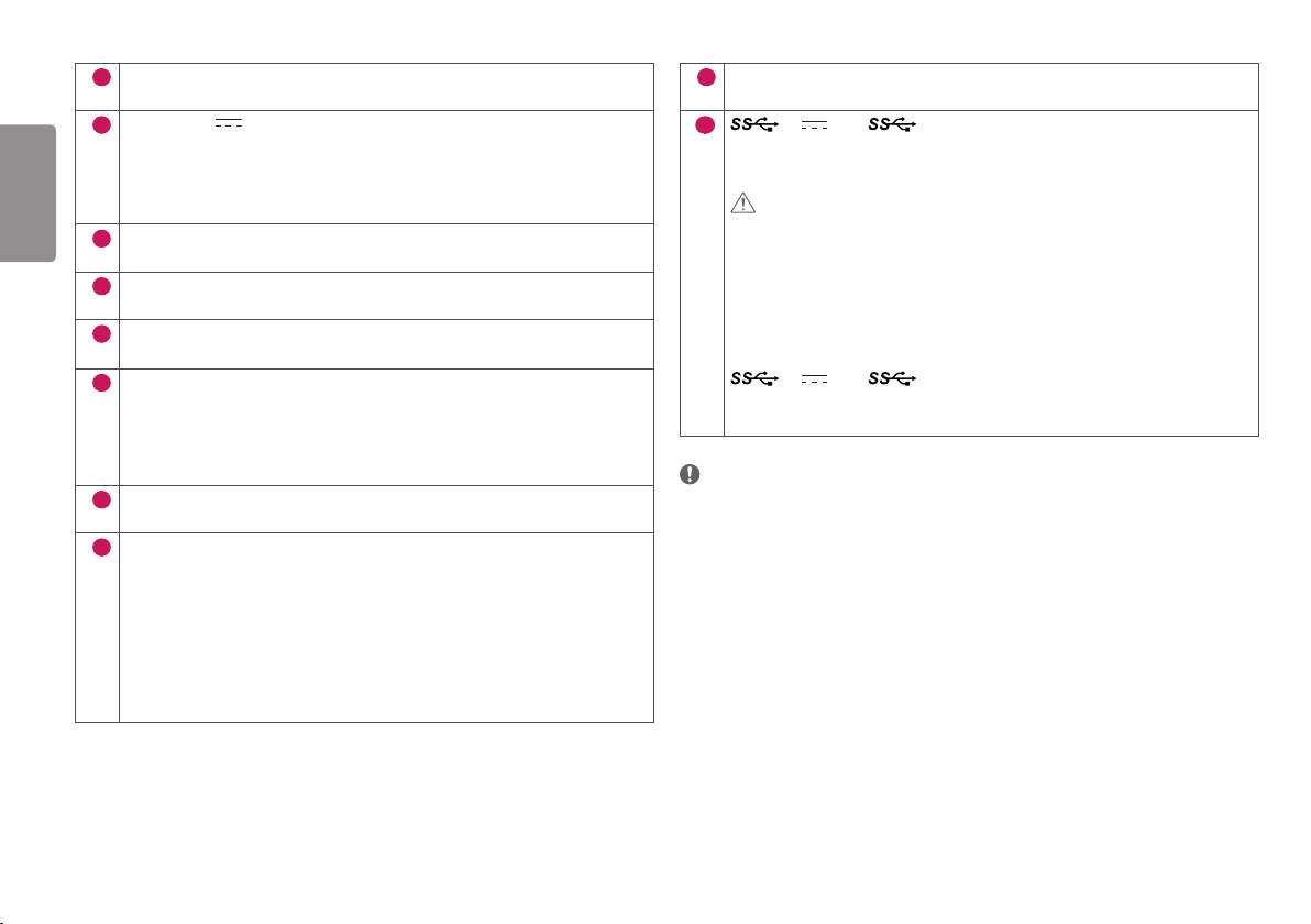
Installing the Monitor
Cable connection and organize
Before connecting the connectors, remove the back door as shown below.
1 Remove the back door by lifting it in the direction of the arrow. The back door is held in place with a magnet.
2 After installing the cables, tidy them up using the cable holders.
10
ENGLISH
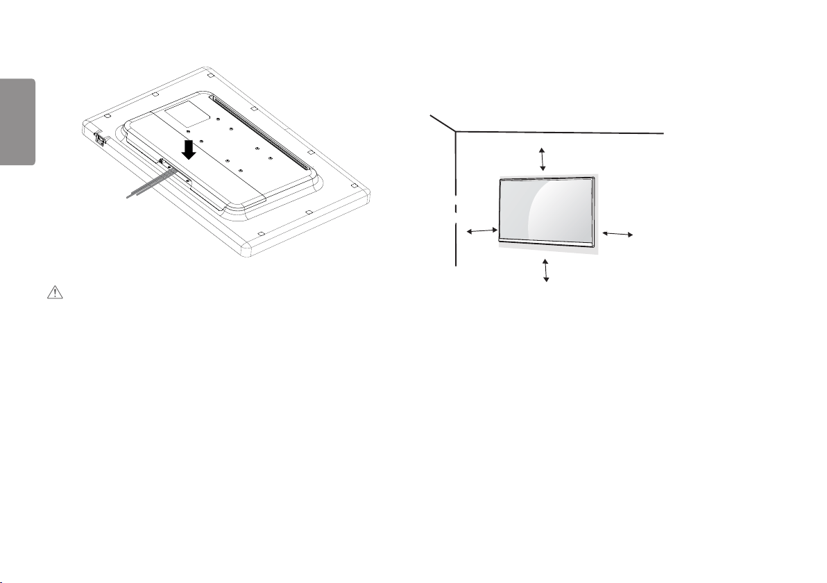
Installing on the Wall
Install the monitor at least 100 mm (3.9 inches) away from the wall on each side of the monitor to ensure
sufficient ventilation. Detailed installation instructions can be obtained from your local dealer. Please refer to the
manual to install and set up a tilting wall mounting bracket.
100 mm
(3.9 inches)
100 mm
(3.9 inches)
100 mm
(3.9 inches)
100 mm
(3.9 inches)
To install the monitor to a wall, attach a wall mount plate (optional) to the back of the monitor.
Make sure that the wall mount plate (optional) is securely fixed to the monitor and to the wall.
1 Using screws longer than the standard length may damage the inside of the product.
2 A non-VESA standard screw may damage the product and cause the monitor to fall. LG Electronics is not
liable for any accidents relating to the use of non-standard screws.
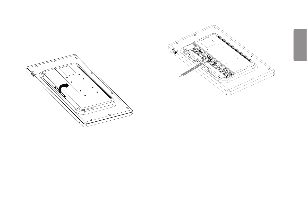
3 After tidying the cables, attach the back door and use the product.
CAUTION
• When the back door is attached to the monitor, the monitor meets water resistance standards. Do not use the
monitor with the back door detached, as the water resistance capability is not guaranteed without the door.
11
ENGLISH
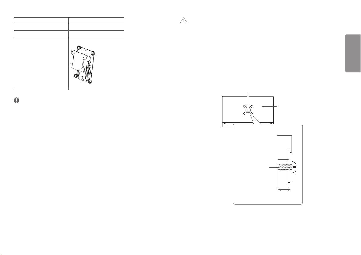
Wall Mount (mm)
100 x 100
Standard screw
M4 x L10
Required screws
4
Wall Mount Plate (optional) RW120
NOTE
• The screws (M4 x L10) can be found fastened in the wall mount screw holes on the back of the monitor.
• Use the screws specified by VESA standards.
• The wall mount kit includes an installation manual and the necessary parts.
• The wall mount plate is an optional item. You can obtain additional accessories from your local dealer.
• The length of screws may differ depending on the wall mount. Be sure to use the proper length.
• For more information, please refer to the manual for the wall mounting bracket.
CAUTION
• Disconnect the power cord first. Then move or install the monitor. There is risk of electric shock.
• Installing the monitor on the ceiling or on a slanted wall may result in the monitor falling off, which could lead
to injury. Use an authorized LG wall mount and contact the local dealer or qualified personnel.
• Applying excessive force when tightening screws may damage the monitor. Such damage is not covered by the
product warranty.
• Use the wall mounting bracket and screws that confirm to VESA standards. Damage caused by the use or
misuse of inappropriate components is not covered by the product warranty.
• When measured from the back of the monitor, the length of each installed screw must be 8 mm (0.3 inches)
or less.
Wall mount plate
Back of the monitor
Screw specifications
: M4 x L10
Wall mount plate
Back of the monitor
Max. 8 mm
(0.3 inches)
12
ENGLISH
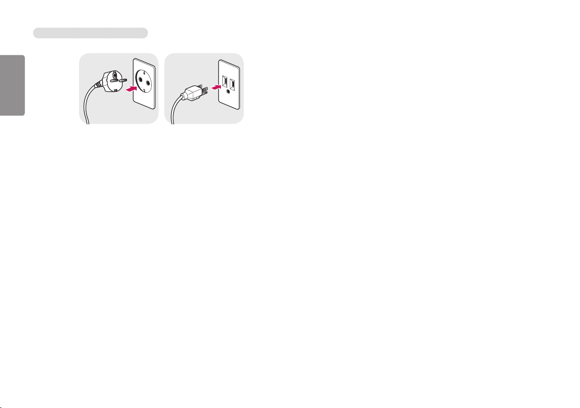
Precautions for Connecting the Power Cord
100-240 V ~
• Make sure to use the power cord that is provided in the product package. Connect the cord to a grounded power
outlet.
• If you need another power cord, please contact your local dealer or the nearest retail store.
13
ENGLISH
USER SETTINGS
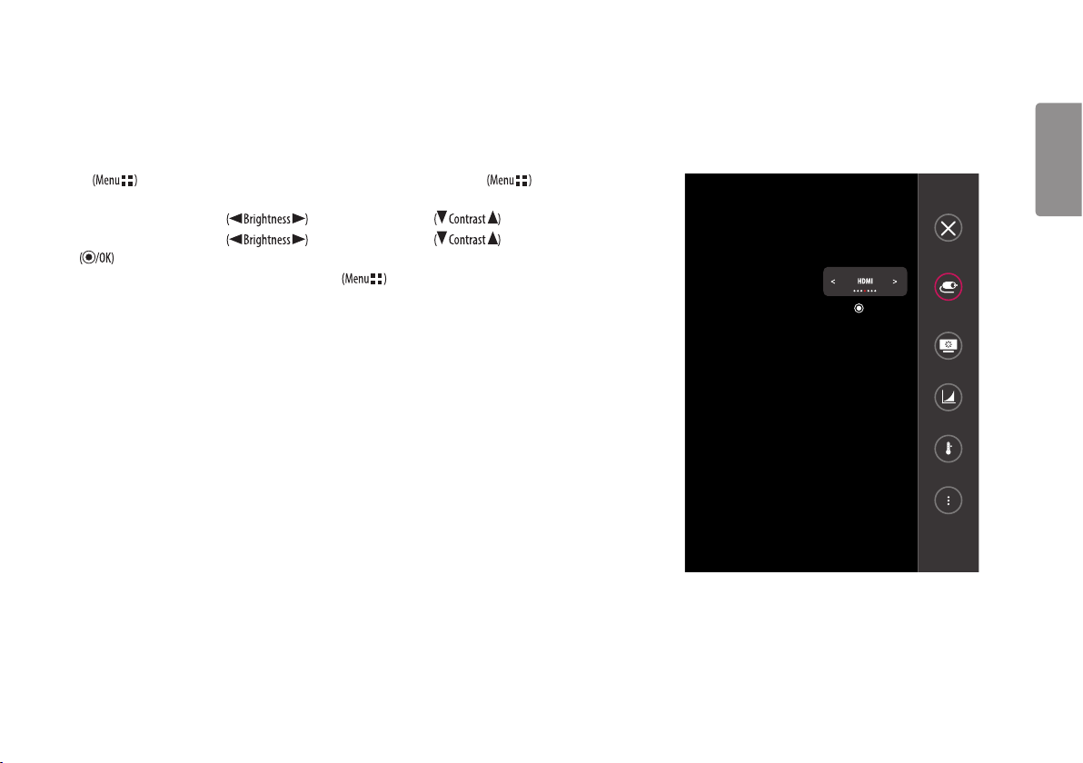
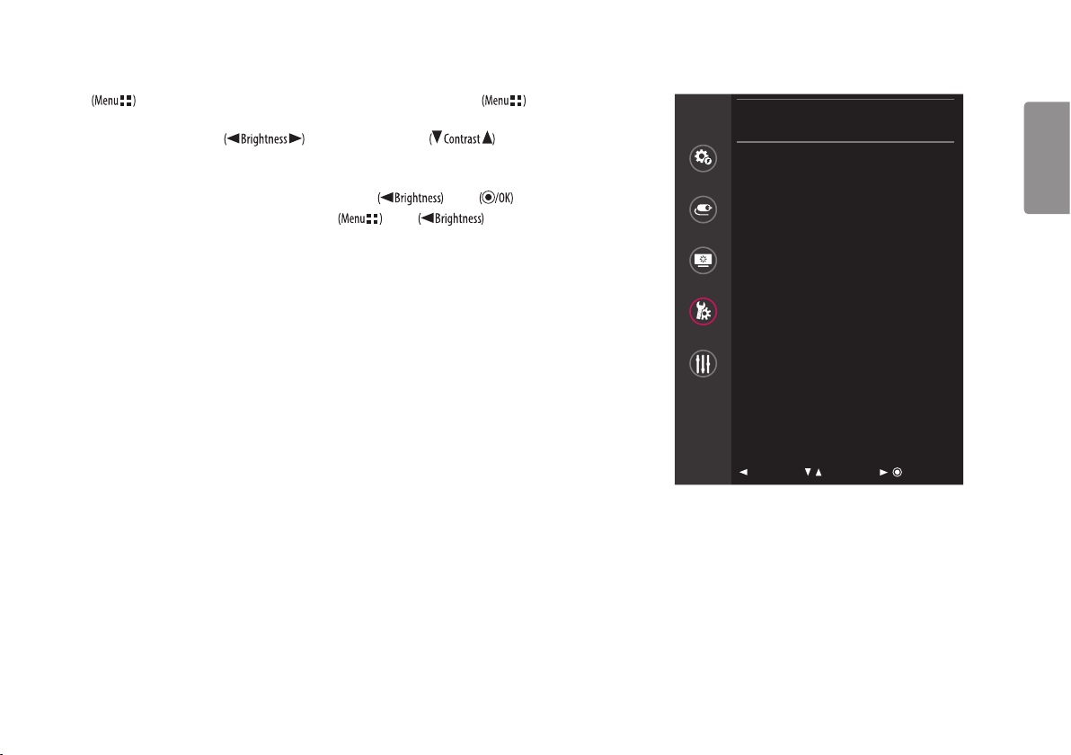
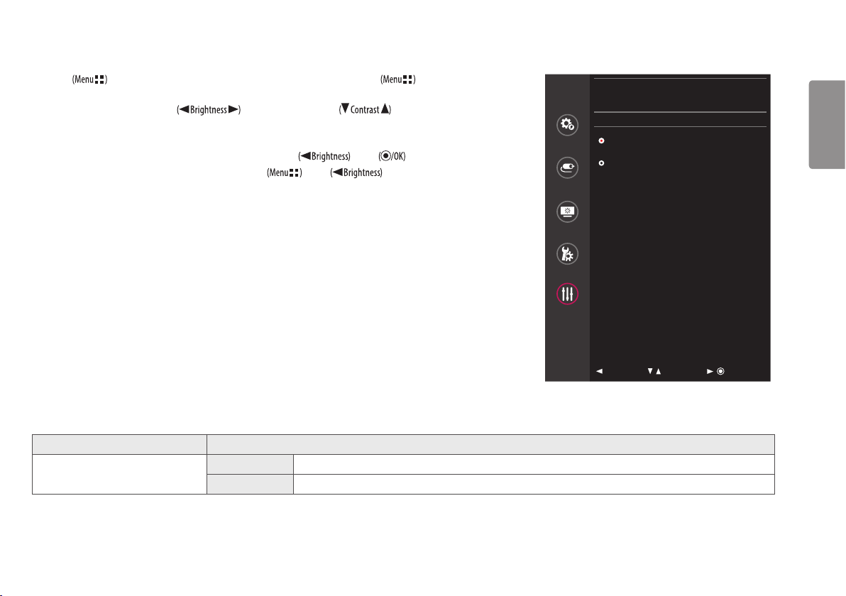
Activating the Quick Menu
1 Press to activate the LED Control Button. When the LED Control button is activated, press to show the OSD Quick
Menu.
2 Among the LED Control Button, press to move to the left or right or to move to the bottom or top.
3 Among the LED Control Button, press to move to the left or right or to move to the bottom or top
or to set options.
4 In order to exit from the OSD Menu, press the LED Control Button or select [Exit].
Exit
Input
: Ok
Picture Mode
Gamma
Color Temp
All Settings
14
ENGLISH
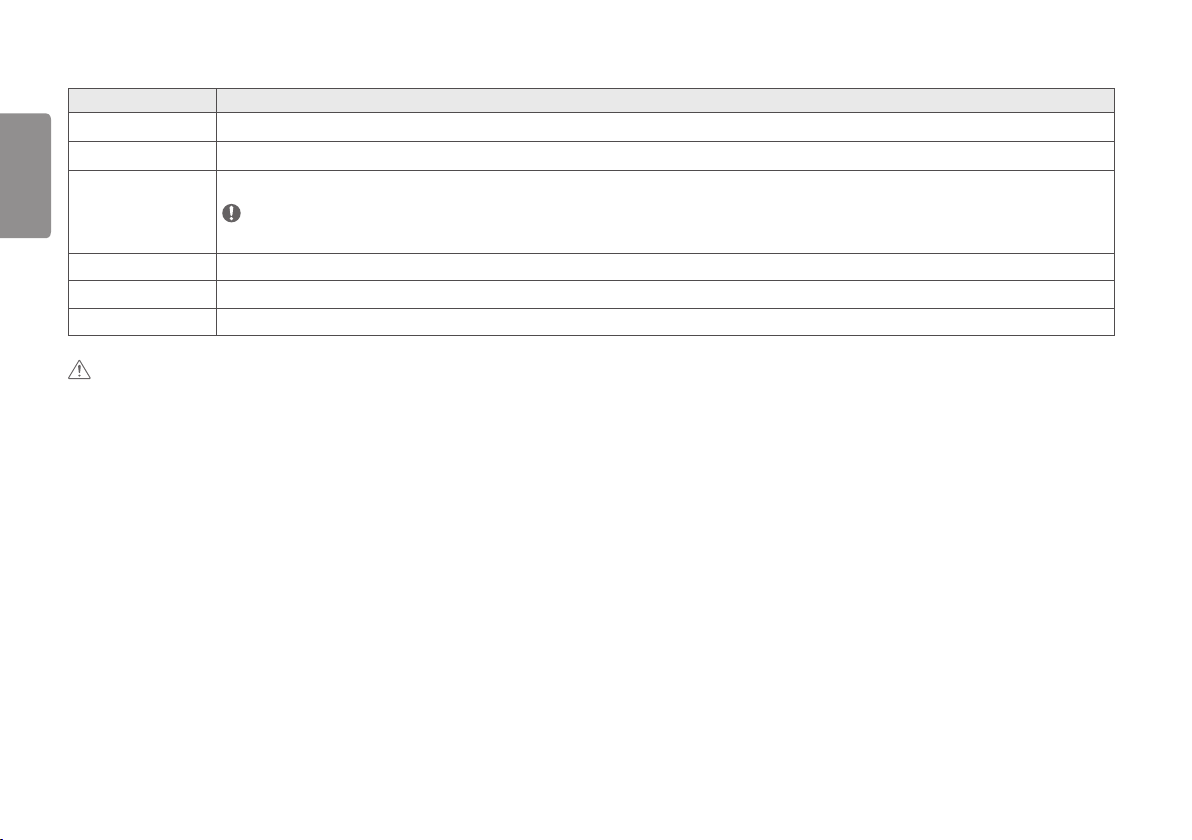
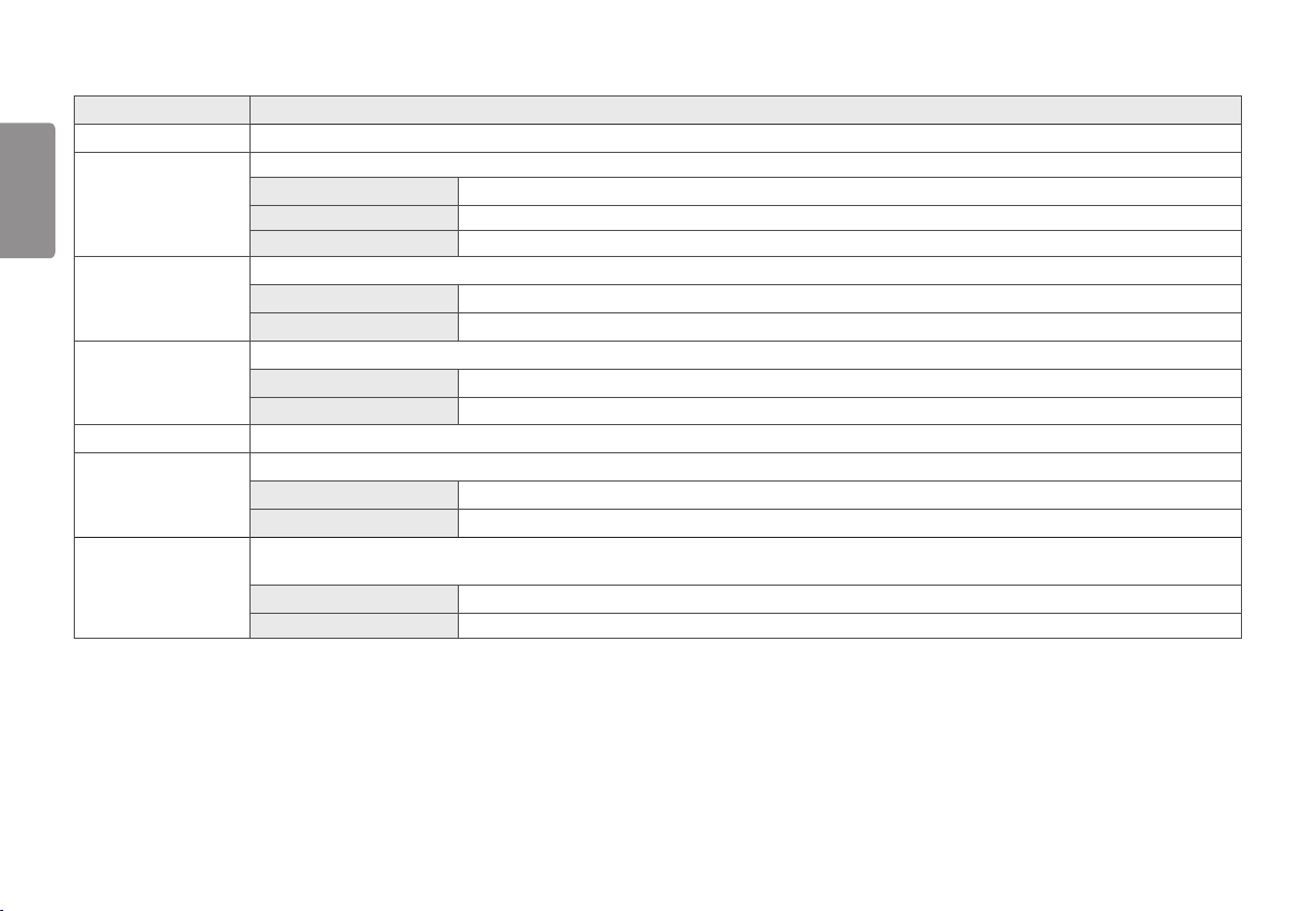
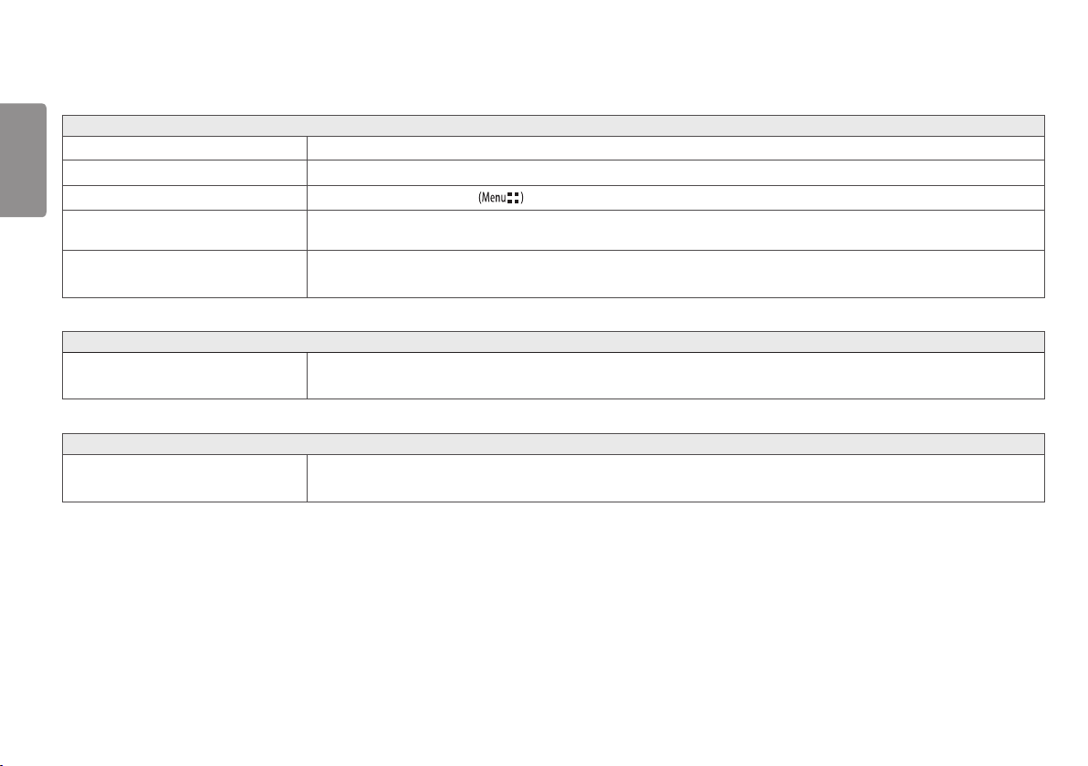
The applicable setting options are as shown below.
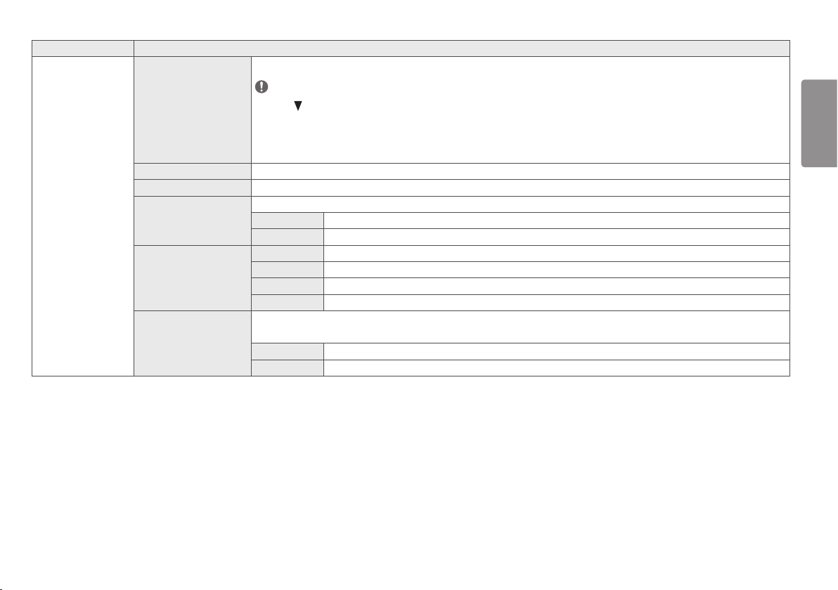
Quick Menu Settings Explanation
[Exit]
Closes the Quick Menu.
[Input]
Selects the applicable input mode.
[Picture Mode] Selects the [Picture Mode].
NOTE
• If the [Picture Mode] is not the [Custom] mode, [Gamma] and [Color Temp] will be deactivated.
[Gamma] Selects the screen's [Gamma].
[Color Temp] Selects the screen's [Color Temp].
[All Settings] Enters the All Settings menu.
CAUTION
• The Monitor OSD (On Screen Display) may differ from the description in the User Manual.
15
ENGLISH
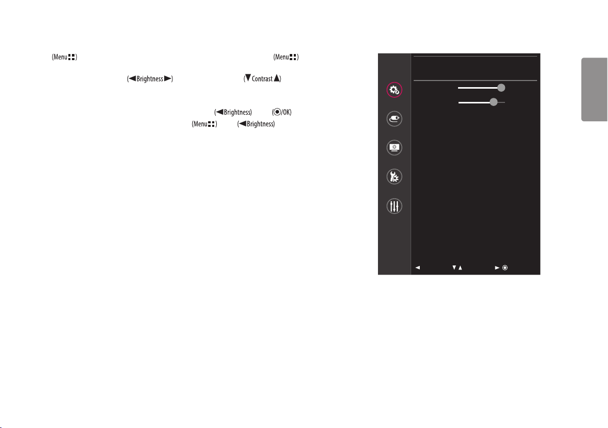
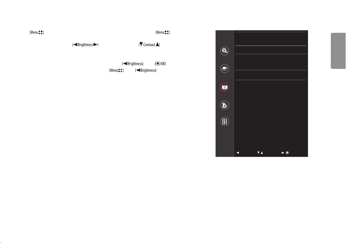
Quick Settings
1 Press to activate the LED Control Button. When the LED Control Button is activated, press and select [All Settings]
to show the complete OSD Menu.
2 Among the LED Control Button, press to move to the left or right or to move to the bottom or top to
go to the [Quick Settings].
3 Configure the options following the instructions that appear in the bottom right corner.
4 To configure an upper menu or another item, press the LED Control Button or press to move to the settings.
5 In order to exit from the OSD Menu, press the LED Control Button or press .
Quick Settings
Quick Settings
Brightness
100 >
Contrast
70 >
Input
Hot key Settings
>
User Preset
>
Picture
General
Auto
Configuration
: Exit / : Move
/ : Ok
16
ENGLISH
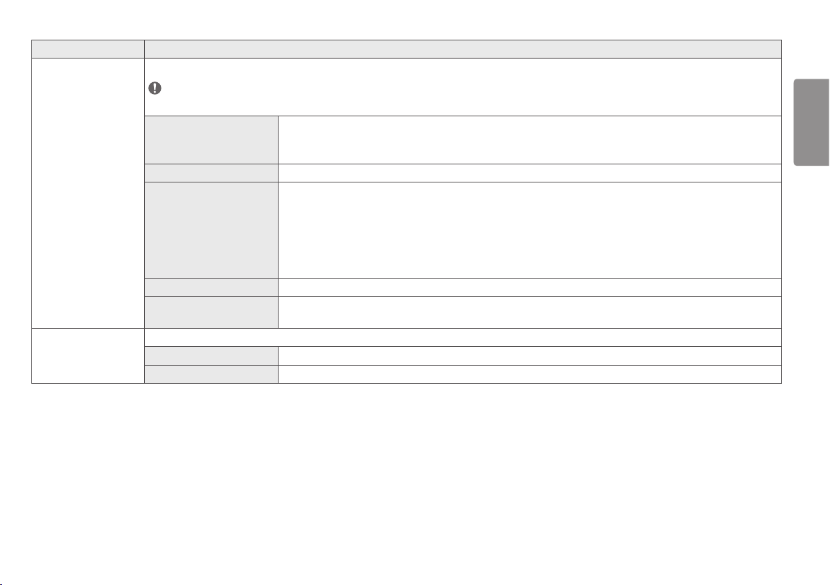
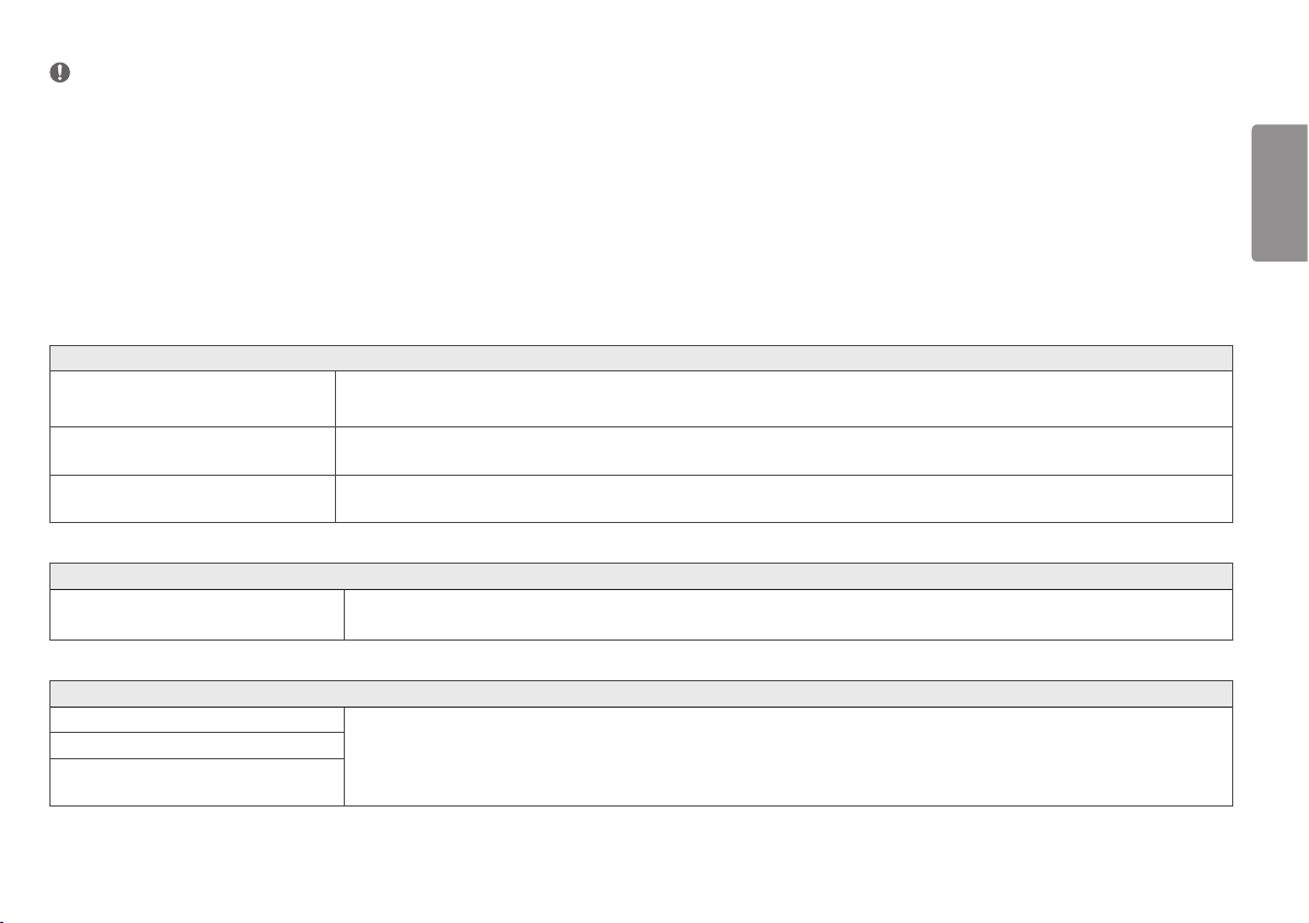
The applicable setting options are as shown below.
[All Settings] > [Quick
Settings]
Explanation
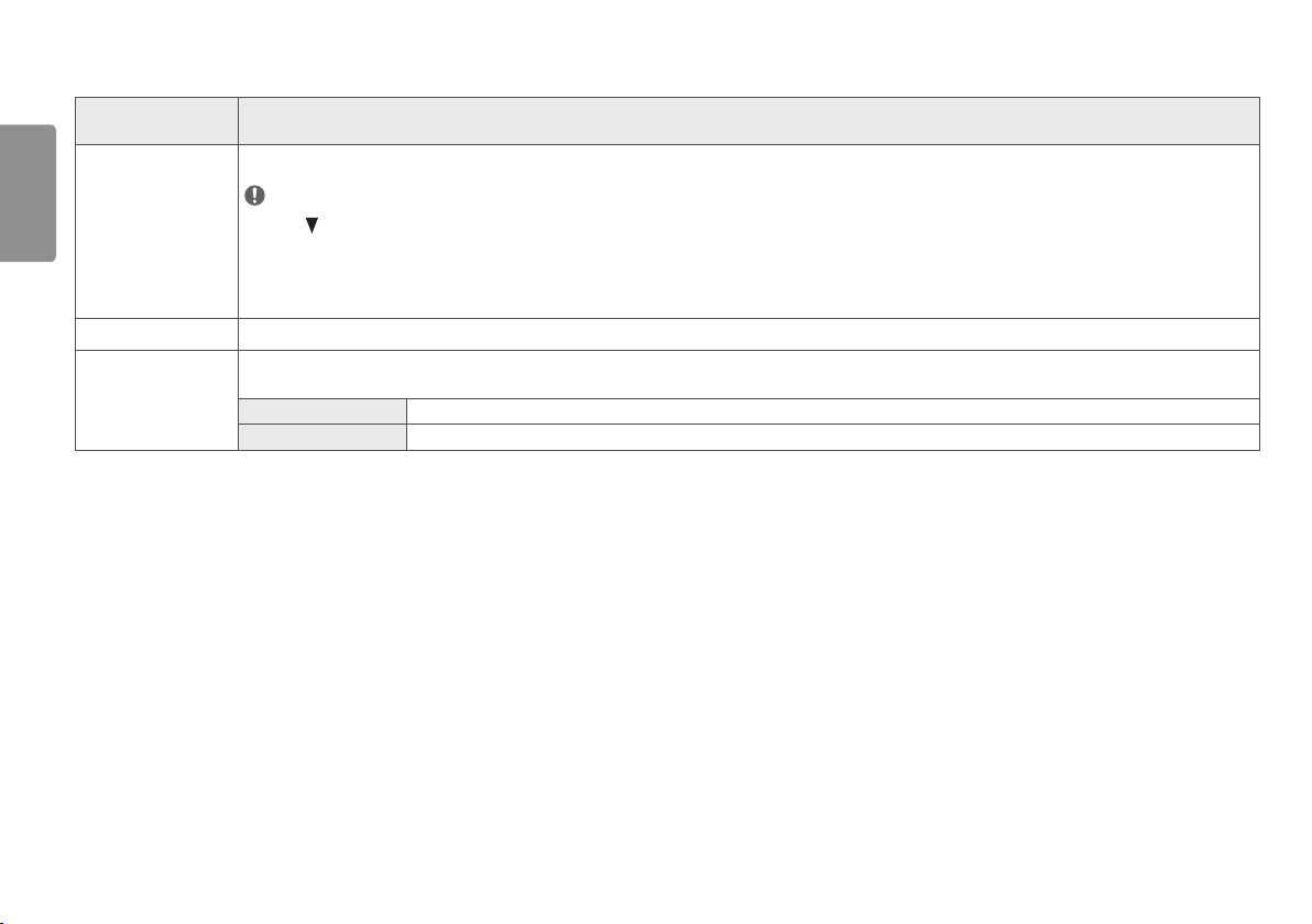
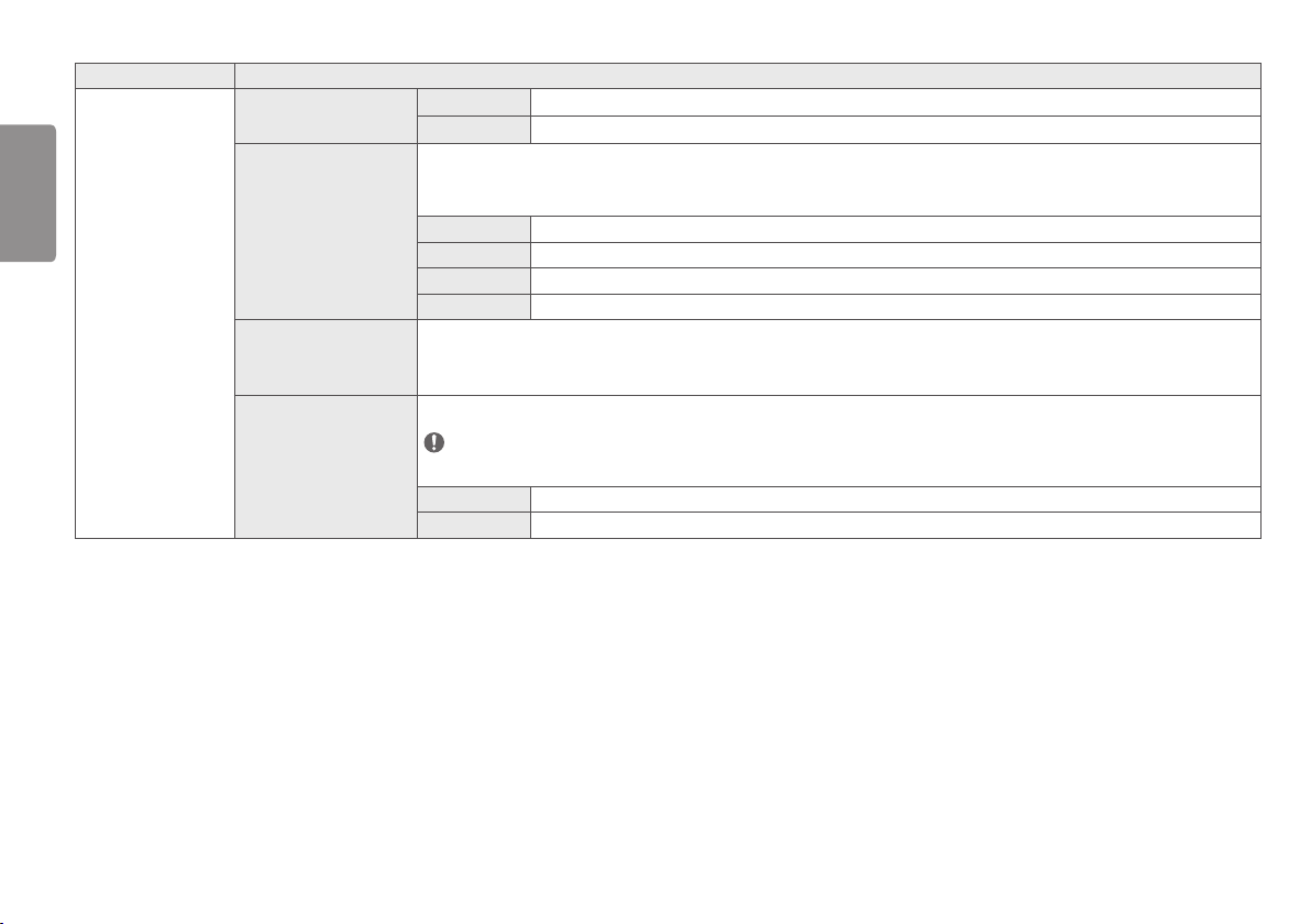
[Brightness]
Adjusts screen brightness.
NOTE
• Press the button to toggle between [Turn on 'Brightness Stabilization']/[Turn off 'Brightness Stabilization'].
• When [Brightness Stabilization] is [On] , the [Brightness] adjustment function is deactivated.
• When [Brightness Stabilization] is [On], [SMART ENERGY SAVING] and [DFC] functions are deactivated.
• When [Picture Mode] is set as [DICOM], or [Gamma] is set as [DICOM Gamma Curve] Setting, the [Brightness] adjustment function is deactivated.
[Contrast]
Adjusts the color contrast of the screen.
[Hot key Settings] Designate a hotkey for screen image settings. After setting the hotkey, use the hotkey in the LED Control Button to enable the set menu. ([PIP Size], [Mono], [Color Temp], [Gamma], [Black Stabilizer],
[Screen Zoom], [Off])
[Hotkey 1] Select a function to use with [Hotkey 1].
[Hotkey 2] Select a function to use with [Hotkey 2].
17
ENGLISH
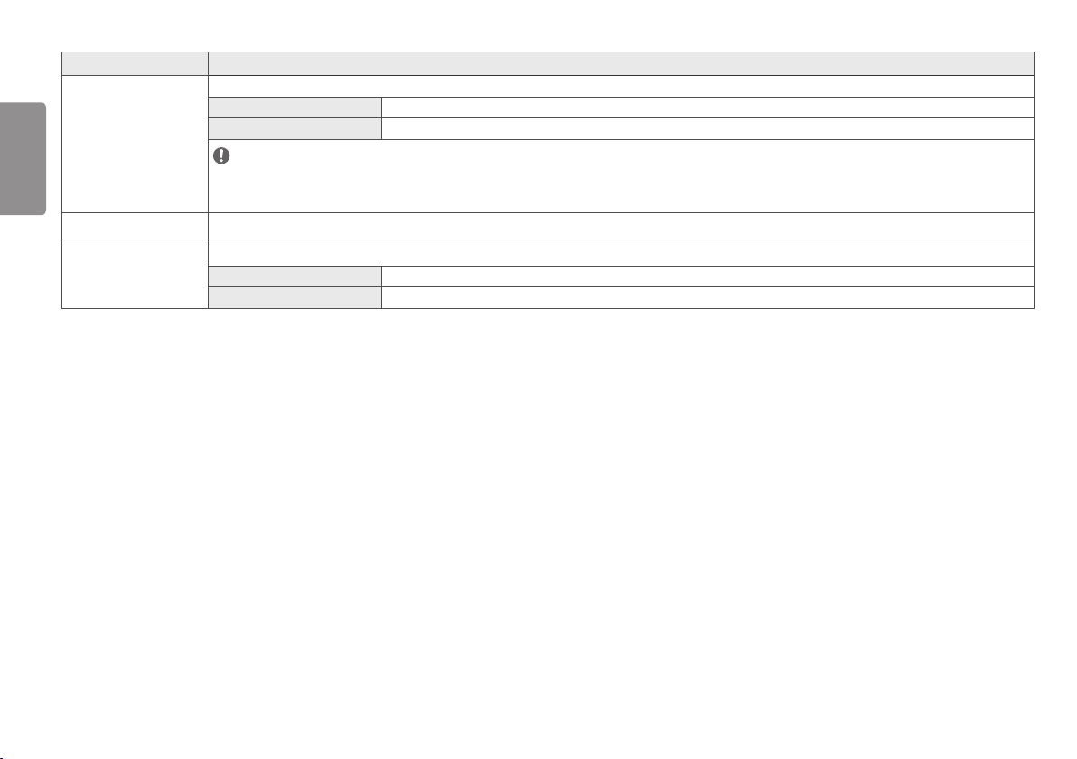
[All Settings] > [Quick
Settings]
Explanation
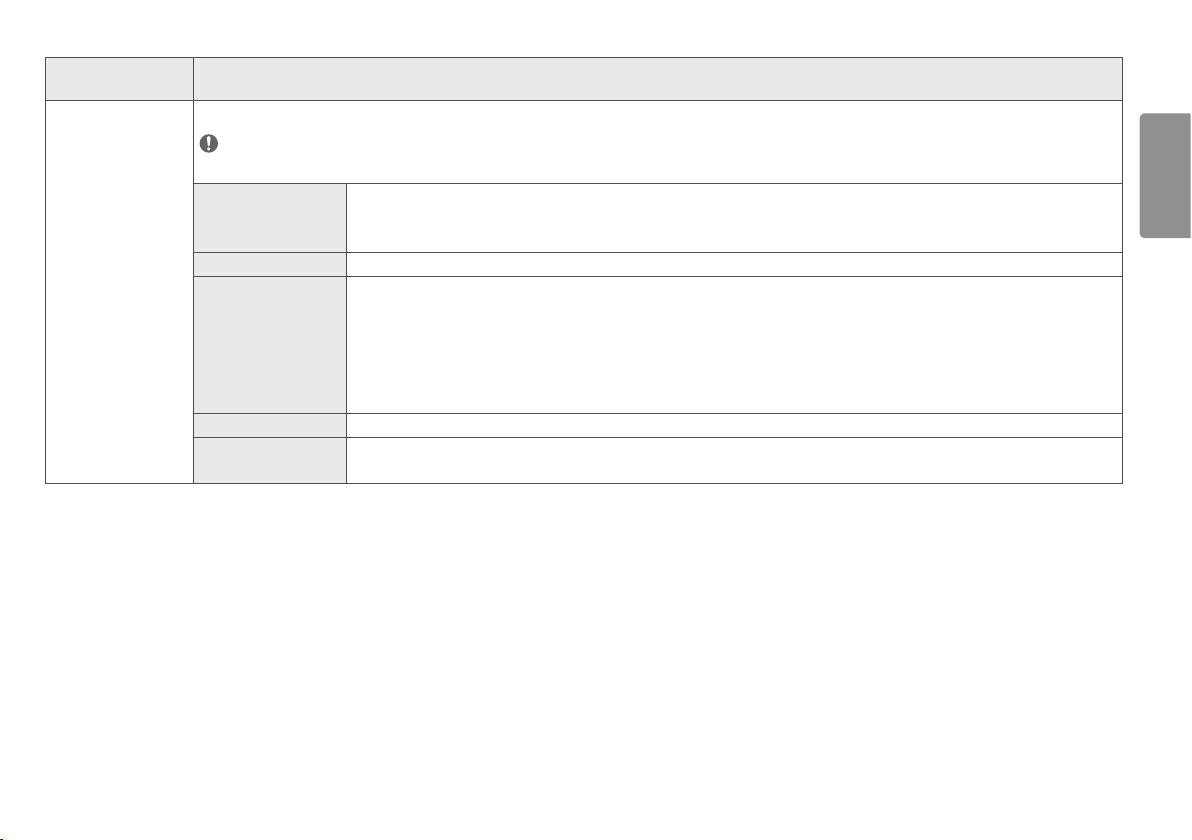
[User Preset] User Preset allows the user to save or load up to 10 picture quality settings for multiple connected devices in each preset.
NOTE
• You can use User Preset to import or save items in [Picture Adjust] and [Color Adjust] of the [Picture] menu.
[User Name] Allows the user to change and register a user name ([Preset 1] ~ [Preset 3], [User 1] ~ [User 7]) as the user wants.
The user can enter a user name to be registered by using the screen keyboard.
[Preset 1] ~ [Preset 3] are factory-set user names as samples and the user can change the names.
[Load User Settings] Allows the user to change the picture quality settings by loading the User Preset settings.
[Save User Settings] Saves the current picture quality settings in the corresponding User Preset.
[Preset 1] ~ [Preset 3] are factory-set values as samples and the user can change the values.
• [Preset 1]: Use this preset for bluish color.
• [Preset 2]: Use this preset for greenish color and brighter low-gradation.
• [Preset 3]: Use this preset to soften the red tone.
• [User 1] ~ [User 7]: Initial values are the same as the factory settings.
[Default User Settings] Loads the initial basic picture settings.
[User Preset Reset] Initializes User Preset settings.
• Initializes the existing user name and user settings to be restored to factory settings ([Preset 1] ~ [Preset 3], [User 1] ~ [User 7]).
18
ENGLISH
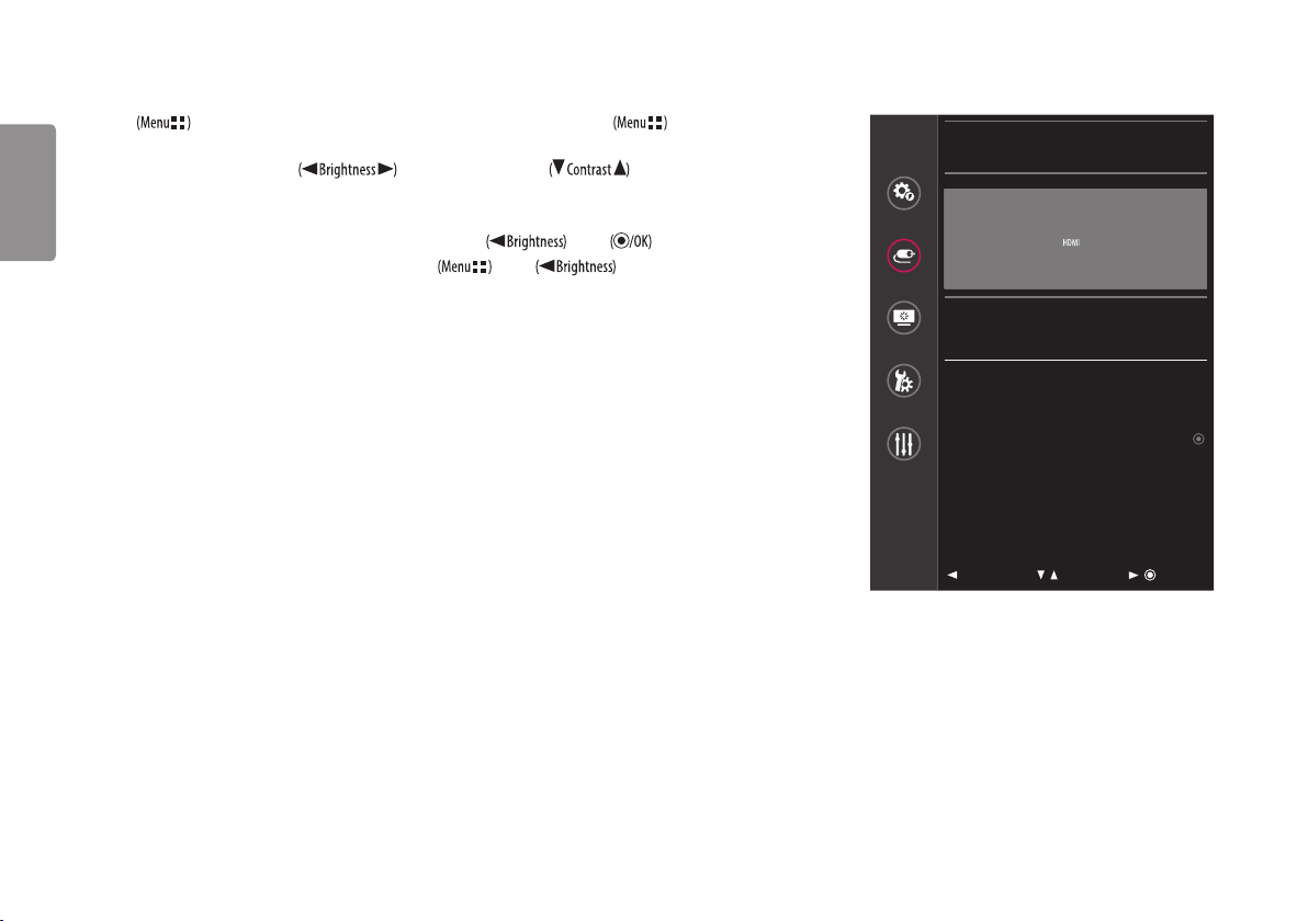
Input
1 Press to activate the LED Control Button. When the LED Control Button is activated, press and select [All Settings] to
show the complete OSD Menu.
2 Among the LED Control Button, press to move to the left or right or to move to the bottom or top to go
to the [Input].
3 Configure the options following the instructions that appear in the bottom right corner.
4 To configure an upper menu or another item, press the LED Control Button or press to move to the settings.
5 In order to exit from the OSD Menu, press the LED Control Button or press .
Input
Quick Settings
Input
Picture
Main Input List HDMI
>
Aspect Ratio Full Wide
>
General
PBP / PIP
>
PIP Size Small
>
Auto
Configuration
Main/Sub Screen Change
: Exit / : Move
/ : Ok
19
ENGLISH
The applicable setting options are as shown below.
[All Settings] > [Input] Explanation
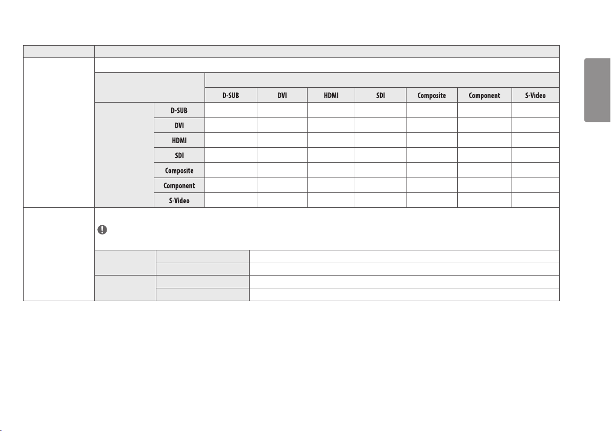
[Main Input List]
[Sub Input List]
Selects the input mode.
PBP / PIP Connection
[Sub]
[Main]
- - O O - - -
- - O O - - -
O O - O O O O
O O O - O O O
- - O O - - -
- - O O - - -
- - O O - - -
[Aspect Ratio] Adjusts the aspect ratio of the screen. ([Full Wide], [Original], [Just Scan])
NOTE
• The display may look the same for [Full Wide], [Original] and [Just Scan] options at the recommended resolution (1920 x 1080).
[Main Aspect Ratio] [Full Wide] Displays the image to fit the PBP / PIP screen, regardless of the video signal input.
[Original] Displays on the PBP / PIP screen in the aspect ratio of the video signal input.
[Sub Aspect Ratio] [Full Wide] Displays the image to fit the PBP / PIP screen, regardless of the video signal input.
[Original] Displays on the PBP / PIP screen in the aspect ratio of the video signal input.
20
ENGLISH
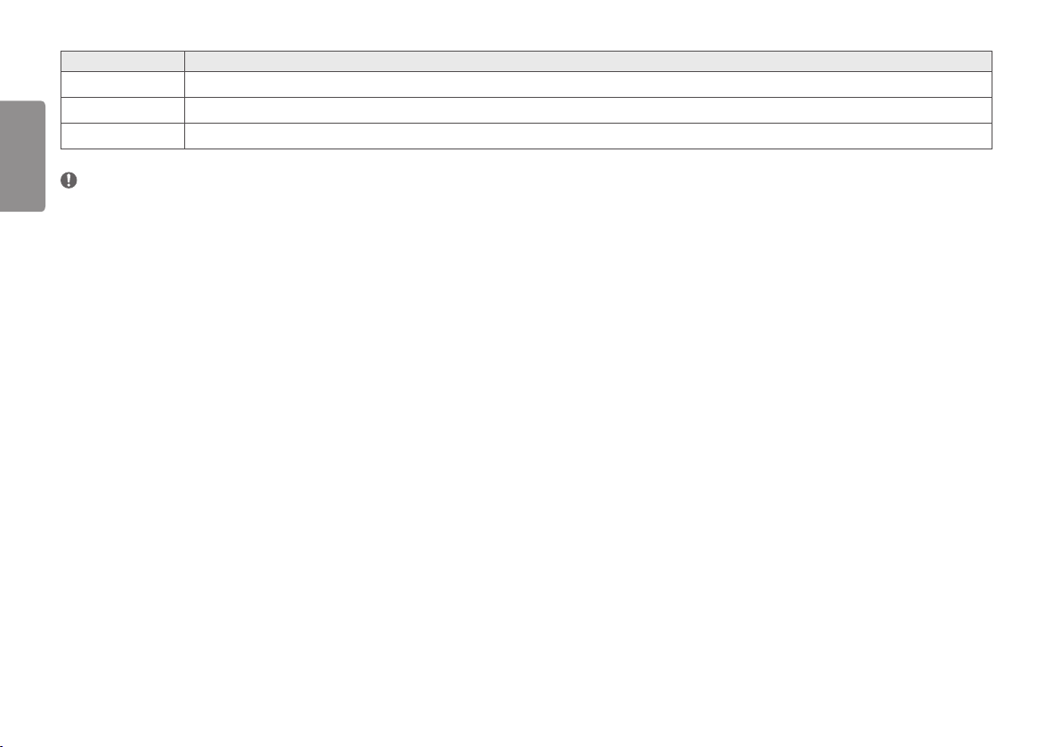
[All Settings] > [Input] Explanation
[PBP / PIP]
Displays screens of two input modes on a single monitor at the same time.
[PIP Size]
Adjusts the size of PIP. ([Small], [Medium], [Large])
[Main/Sub Screen Change]
Converts between the Main and the Sub in the [PBP / PIP] mode.
NOTE
• If not using the [PBP / PIP] feature, [PIP Size], [Main/Sub Screen Change] are deactivated.
• You can connect a PC analogue (D-SUB) input source to the DVI-I input connector by using the DVI-I to D-SUB gender cable. In order to use a D-SUB input, use the DVI-I to D-SUB gender cable included in the box.
21
ENGLISH
Picture
1 Press to activate the LED Control Button. When the LED Control Button is activated, press and select [All Settings]
to show the complete OSD Menu.
2 Among the LED Control Button, press to move to the left or right or to move to the bottom or top to
go to the [Picture].
3 Configure the options following the instructions that appear in the bottom right corner.
4 To configure an upper menu or another item, press the LED Control Button or press to move to the settings.
5 In order to exit from the OSD Menu, press the LED Control Button or press .
Picture
Quick Settings
Picture Mode Custom >
Picture Adjust >
Input
Color Adjust >
Configuration Adjust >
Picture
Picture Reset >
General
Auto
Configuration
: Exit / : Move
/ : Ok
22
ENGLISH
The applicable setting options are as shown below.
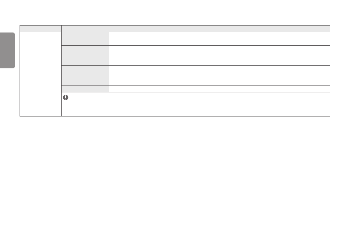
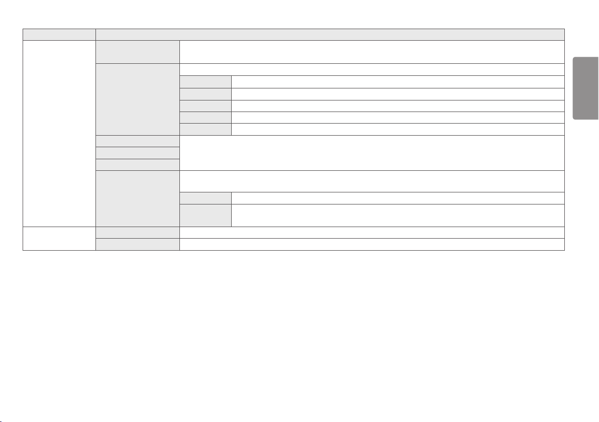
[All Settings] > [Picture] Explanation
[Picture Mode]
[Custom] Allows the user to adjust each element. The color mode of the main menu can be adjusted.
[Mono] Mono (black and white) color mode.
[sRGB] The standard RGB color mode for monitors and printers.
[EBU] The standard TV PAL color mode for broadcasting.
[REC709] The standard HDTV color mode for broadcasting.
[SMPTE-C] The standard TV NTSC color mode for broadcasting.
[DICOM] A mode that optimizes the screen settings so you can view images for medical use.
[Calibration 1] Configures to the last calibrated (corrected) screen.
[Calibration 2] Configures to a previously calibrated (corrected) screen.
NOTE
• The [Brightness Stabilization] function is operated in [Custom].
• [Calibration 2]: If you use Calibration after installing the TRUE COLOR PRO program, the applicable menu will be activated.
23
ENGLISH
[All Settings] > [Picture] Explanation
[Picture Adjust] [Brightness] Adjusts screen brightness.
NOTE
• Press the button to toggle between [Turn on 'Brightness Stabilization']/[Turn off 'Brightness Stabilization'].
• When [Brightness Stabilization] is [On] , the [Brightness] adjustment function is deactivated.
• When [Brightness Stabilization] is [On], [SMART ENERGY SAVING] and [DFC] functions are deactivated.
• When [Picture Mode] is set as [DICOM], or [Gamma] is set as [DICOM Gamma Curve] Setting, the [Brightness] adjustment function is deactivated.
[Contrast]
Adjusts the color contrast of the screen.
[Sharpness] Adjusts the sharpness of the screen.
[Brightness Stabilization] A function for maintaining a set brightness appropriate for treatment environments.
[On] Automatically adjusts brightness.
[Off] Deactivates the applicable function and the user can adjust the brightness.
[SUPER RESOLUTION+] [High] Select this option for crystal clear images.
[Middle] The optimized picture quality is displayed when a user wants images between low and high modes for comfortable viewing.
[Low] The optimized picture quality is displayed when a user wants smooth and natural images.
[Off] Select this option for the normal user experience. Deactivates the [SUPER RESOLUTION+] function.
[Black Level] Sets up the offset level. (HDMI only)
• Offset: as a reference for a video signal, this is the darkest color the monitor can display.
[High] Maintains the current screen contrast range.
[Low] Reduces the black levels and increases the white levels of the current screen contrast range.
24
ENGLISH
[All Settings] > [Picture] Explanation
[Picture Adjust] [DFC] [On] Automatically adjusts brightness depending on the screen.
[Off] Deactivates the [DFC] function.
[Response Time] Sets a response time for displayed pictures based on the movement of the picture on the screen.
In a normal environment, it is recommended that you set [Fast]. For images with a lot of motion, it is recommended that you set [Faster]. But, when [Faster] is set,
it may cause an afterimage.
[Faster] Sets the response time to Faster.
[Fast] Sets the response time to Fast.
[Normal] Sets the response time to Normal.
[Off] Does not use the response time improvement feature.
[Black Stabilizer] Adjusts the black level to clearly see objects on a dark screen.
Increasing the [Black Stabilizer] value brightens the low grey levels on the screen. (You can easily distinguish objects on a dark game screen.)
Reducing the [Black Stabilizer] value darkens the low grey levels and increases the dynamic contrast on the screen.
[Uniformity] Automatically adjusts the brightness uniformity of the screen.
NOTE
• If [Uniformity] is activated, the screen may become darker.
[On] Activates the [Uniformity] function.
[Off] Deactivates the [Uniformity] function.
25
ENGLISH
[All Settings] > [Picture] Explanation
[Color Adjust] [Gamma] Set your own gamma value. ([Gamma 1.8], [Gamma 2.0], [Gamma 2.2], [Gamma 2.4], [Gamma 2.6], [DICOM Gamma Curve])
Higher gamma settings mean a darker image is displayed or vice versa.
[Color Temp] Set your own color temperature. ([Custom], [6500K], [7500K], [9300K], [Manual])
[Custom] Users can customize the red, green and blue color.
[6500K] Indicates the screen color with a 6500K red color temperature.
[7500K] Sets the screen color between red and blue with a 7500K color temperature.
[9300K] Indicates the screen color with 9300K blue color temperature.
[Manual] Adjusts the color temperature in 500K increments. (However, supports 9300K instead of 9500K)
[Red]
You can customize the picture color using Red, Green and Blue color.[Green]
[Blue]
[Six Color] Meets the user requirements for color by adjusting the hue and saturation of the six color (red, green, blue, cyan, magenta and yellow) and then saving the
settings.
[Hue] Adjusts the tint of the screen color.
[Saturation] The lower the screen's color sharpness value, the less sharper and brighter the color become. The higher the value, the sharper and darker
the color become.
[Configuration Adjust] [Horizontal] [Vertical] Adjusts the position of the screen.
[Clock] [Phase] Improves the sharpness and stability of the screen.
26
ENGLISH
[All Settings] > [Picture] Explanation
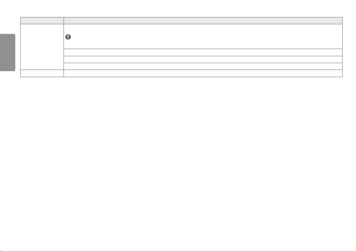
[Resolution] A user can set the desired resolution. This option is available only when the screen resolution of the computer is set as below (only for the D-SUB).
NOTE
• When the resolution selected by a user is different from the resolution outputted by the PC per computer, the function will be deactivated.
[1024 x 768], [1280 x 768], [1360 x 768], [1366 x 768], [Off]
[1280 x 960], [1600 x 900], [Off]
[1440 x 900], [1600 x 900], [Off]
[Picture Reset] Returns color to the default settings.
27
ENGLISH
General
1 Press to activate the LED Control Button. When the LED Control Button is activated, press and select [All Settings] to
show the complete OSD Menu.
2 Among the LED Control Button, press to move to the left or right or to move to the bottom or top to go
to the [General].
3 Configure the options following the instructions that appear in the bottom right corner.
4 To configure an upper menu or another item, press the LED Control Button or press to move to the settings.
5 In order to exit from the OSD Menu, press the LED Control Button or press .
General
Quick Settings
Language English
>
SMART ENERGY SAVING Off
>
Input
HW Calibration Off
>
RS-232C
>
Picture
LED Control Button 20Sec Time Out
>
DVI Power Supply Off
>
General
Hot key Settings
>
User Preset
>
Auto
Configuration
Auto Screen Off Off
>
OSD Lock Off
>
Information
>
Reset
>
: Exit / : Move
/ : Ok
28
ENGLISH
The applicable setting options are as shown below.
[All Settings] > [General]
Explanation
[Language] Sets the menu screen to the desired language.
[SMART ENERGY SAVING] Conserve energy by using luminance compensation algorithm.
[High] Saves energy using the high-efficiency [SMART ENERGY SAVING] feature.
[Low] Saves energy using the low-efficiency [SMART ENERGY SAVING] feature.
[Off] Disables the [SMART ENERGY SAVING] function.
[HW Calibration] [RS-232C] and the [HW Calibration] cannot be used at the same time.
[On] The HW Calibration function will operate.
[Off] The HW Calibration function will be turned off.
[RS-232C] [RS-232C] and the [HW Calibration] cannot be used at the same time.
[Serial Port] The [RS-232C] function will be operated or turned off.
[Set ID] Adjusts [Set ID]. (The scope of adjustment: 1-10)
[LED Control Button] Adjusts the ON time of the Control Button. ([Always On], [20Sec Time Out], [10Sec Time Out], [5Sec Time Out])
[DVI Power Supply] Supplies power to a device used by connecting to a DVI input terminal in the form of dongle without power.
[On] Activates the [DVI Power Supply] function.
[Off] Deactivates the [DVI Power Supply] function.
[Hot key Settings] Designate a hotkey for screen image settings. After setting the hotkey, use the hotkey in the LED Control Button to enable the set menu. ([PIP Size], [Mono], [Color Temp], [Gamma], [Black
Stabilizer], [Screen Zoom], [Off])
[Hotkey 1] Select a function to use with [Hotkey 1].
[Hotkey 2] Select a function to use with [Hotkey 2].
29
ENGLISH
[All Settings] > [General]
Explanation
[User Preset] User Preset allows the user to save or load up to 10 picture quality settings for multiple connected devices in each preset.
NOTE
• You can use User Preset to import or save items in [Picture Adjust] and [Color Adjust] of the [Picture] menu.
[User Name] Allows the user to change and register a user name ([Preset 1] ~ [Preset 3], [User 1] ~ [User 7]) as the user wants.
The user can enter a user name to be registered by using the screen keyboard.
[Preset 1] ~ [Preset 3] are factory-set user names as samples and the user can change the names.
[Load User Settings] Allows the user to change the picture quality settings by loading the User Preset settings.
[Save User Settings] Saves the current picture quality settings in the corresponding User Preset.
[Preset 1] ~ [Preset 3] are factory-set values as samples and the user can change the values.
• [Preset 1]: Use this preset for bluish color.
• [Preset 2]: Use this preset for greenish color and brighter low-gradation.
• [Preset 3]: Use this preset to soften the red tone.
• [User 1] ~ [User 7]: Initial values are the same as the factory settings.
[Default User Settings] Loads the initial basic picture settings.
[User Preset Reset] Initializes User Preset settings.
• Initializes the existing user name and user settings to be restored to factory settings ([Preset 1] ~ [Preset 3], [User 1] ~ [User 7]).
[Auto Screen Off] Automatically turns off the screen when there is no monitor signal for a set time period.
[On] Activates [Auto Screen Off] function.
[Off] Deactivates [Auto Screen Off] function.
30
ENGLISH
[All Settings] > [General]
Explanation
[OSD Lock]
A function for restricting menu configuration and adjustment.
[On] Turns on [OSD Lock].
[Off] Turns off [OSD Lock].
NOTE
• Deactivates all functions except the [Quick Settings] menu and [Input] menu's [Input List], [Aspect Ratio] and [PBP / PIP] functions, and the [General] menu's [OSD Lock] and [Information]
functions.
[Information] Displays the total power on time, serial number and resolution information.
[Reset] [Do you want to reset your settings?]
[No] Cancels the selection.
[Yes] Restores the screen settings to the default settings when your monitor was first purchased.
31
ENGLISH
Auto Configuration
1 Press to activate the LED Control Button. When the LED Control Button is activated, press and select [All Settings] to
show the complete OSD Menu.
2 Among the LED Control Button, press to move to the left or right or to move to the bottom or top to go
to the [Auto Configuration].
3 Configure the options following the instructions that appear in the bottom right corner.
4 To configure an upper menu or another item, press the LED Control Button or press to move to the settings.
5 In order to exit from the OSD Menu, press the LED Control Button or press .
Auto Configuration
Quick Settings
Do you want to Auto Configuration?
No
Input
Yes
Picture
General
Auto
Configuration
: Exit / : Move
/ : Ok
The applicable setting options are as shown below.
[All Settings]> [Auto Configuration] Explanation
[Do you want to Auto Configuration?] [No] Cancels the selection.
[Yes] Automatically sets screen to optimal settings.
32
ENGLISH
TROUBLESHOOTING
Nothing is displayed on the screen.
Is the monitor's power cord plugged in? • Check if the power cord is correctly plugged into the power outlet.
Is the power indicator on? • Check the power cable connection and turn on the power switch.
Is the power indicator displaying as green? • Check if the input setting is correct. ( > [All Settings] > [Input])
Is the [Out of Range] message being displayed? • This occurs when signals transferred from the PC (graphics card) are out of the horizontal or vertical frequency range of the monitor. Please see the <Product
Specification> section of this manual to set the appropriate frequency.
Is the [No Signal] message displayed? • This is displayed when the signal cable between the PC and the monitor is missing or disconnected. Check the cable and reconnect it.
The screen retains an image.
Does image sticking occur even when the monitor is
turned off?
• Displaying a still image for a prolonged time may cause damage to the screen, resulting in the retention of the image.
• To extend the lifetime of the monitor, use a screensaver.
The screen is unstable and shakes. / There are shadowy traces left on the screen.
Did you select the appropriate resolution? • If the selected resolution is HDMI 1080i 60/50 Hz (interlaced), the screen may be flickering. Change the resolution to 1080p or the recommended resolution.
33
ENGLISH
NOTE
• Vertical Frequency: In order to display an image, the screen must be refreshed dozens of times per second, like a fluorescent lamp. The number of times the screen is refreshed per second is called vertical frequency, or refresh rate,
and is represented by Hz.
• Horizontal Frequency: The time it takes to display one horizontal line is called the horizontal cycle. If 1 is divided by the horizontal interval, the result is the number of horizontal lines displayed per second. This is called horizontal
frequency and is represented by kHz.
• Check if the graphics card's resolution or frequency is within the range allowed by the monitor and in Windows set it to the recommended (optimal) resolution in Control Panel > Display > Settings. (May differ depending on your
operating system (OS).)
• Not setting the video card to the recommended (optimal) resolution may result in blurred text, a dimmed screen, a truncated display area or misalignment of the display.
• The setting methods may be different depending on the computer or operating system, and some resolutions may not be available depending on the performance of the graphics card. If this is the case, contact the manufacturer of
the computer or graphics card for assistance.
• Normal graphics cards do not support 1920 x 1080 resolution. If the resolution cannot be displayed, contact the manufacturer of your graphics card.
The display color is abnormal.
Does the display appear discolored (16 color)? • Set the number of color to 24 bits (true color) or higher: In Windows Control Panel > Display > Settings > Color Quality (May differ depending on your operating system.)
Does the display color appear unstable or
monochrome?
• Check if the signal cable is connected properly. Reconnect the cable or reinsert the PC's graphics card.
Are there spots on the screen? • When using the monitor, pixilated spots (red, green, blue, white or black) may appear on the screen. This is normal for an LCD screen. It is not an error, nor is it related to the
monitor's performance.
The 'Unknown Monitor' message appears when the monitor is connected.
Did you install the monitor driver? • Install the enclosed monitor driver which is provided with the monitor or go to LG Electronics homepage (
www.lg.com
) to download and install the monitor driver.
• Check whether the plug & play function is supported by referring to the graphics card user manual.
The image is displayed abnormally.
Does the screen area appear abnormal? • If you want to automatically configure display images to optimal settings, enter the [Auto Configuration] function and select [Yes].
Do you see vertical lines on the screen?
Does the screen display horizontal noise, or does the
text appear blurred?
34
ENGLISH
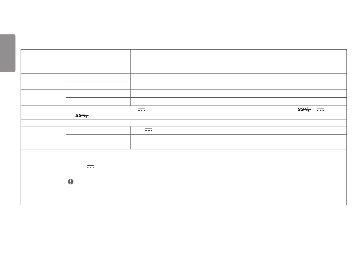
PRODUCT SPECIFICATIONS
In order to improve the product, specifications may change without notice.
The ~ symbol means alternating current, and the symbol means direct current.
LCD Screen Type TFT (Thin Film Transistor)
LCD (Liquid Crystal Display) Screen
Pixel Pitch 0.3114 mm x 0.3114 mm
Resolution Max Resolution
1920 x 1080 @ 60 Hz
Recommended Resolution
Video Signal Horizontal Frequency 30 kHz - 83 kHz
Vertical Frequency 56 Hz - 75 Hz
Input Connector
Potential Equalization Conductor, DC-IN (19 - 24 V ), RS-232C, COMPOSITE IN, S-VIDEO IN, DVI IN, RGBS IN, COMPONENT IN, SDI IN, HDMI IN, SERVICE ONLY, USB ( 5 V 0.9 A),
USB ( )
Output Connector DVI OUT, SDI OUT
Power Sources Power Rating 19 - 24 V 6.32 - 5 A
Power Consumption Max. 120 W
Off Mode: ≤ 0.3 W
AC-DC Adaptor DA-120D19 type, manufactured by Asian Power Devices Inc. (APD)
Input: 100-240 V~ 50-60 Hz, 1.8-0.7 A
Output: 19 V 6.32 A
Classification by protection type against Electric Shock: Class equipment
NOTE
- Connect an AC/DC adapter.
- The output of the enclosed adaptor is 19 V.
- The product is designed to be used with adaptors of the output ranging between 19-24 V. Please use the adaptors of medical standards.
35
ENGLISH
Environmental Conditions Operating Conditions Temperature 0°C to 40°C (32 °F to 104 °F)
Humidity 0% to 80%
Pressure 700 hPa to 1060 hPa
Storing Conditions Temperature -20°C to 60°C (-4 °F to 140 °F)
Humidity 0% to 85%
Pressure 500 hPa to 1060 hPa
Dimensions Monitor Size (Width x Height x Depth)
656.4 x 412.9 x 62.2 (mm)
25.8 x 16.2 x 2.4 (inches)
Weight (Without Packaging) 7.7 (kg)
16.9 (lbs)
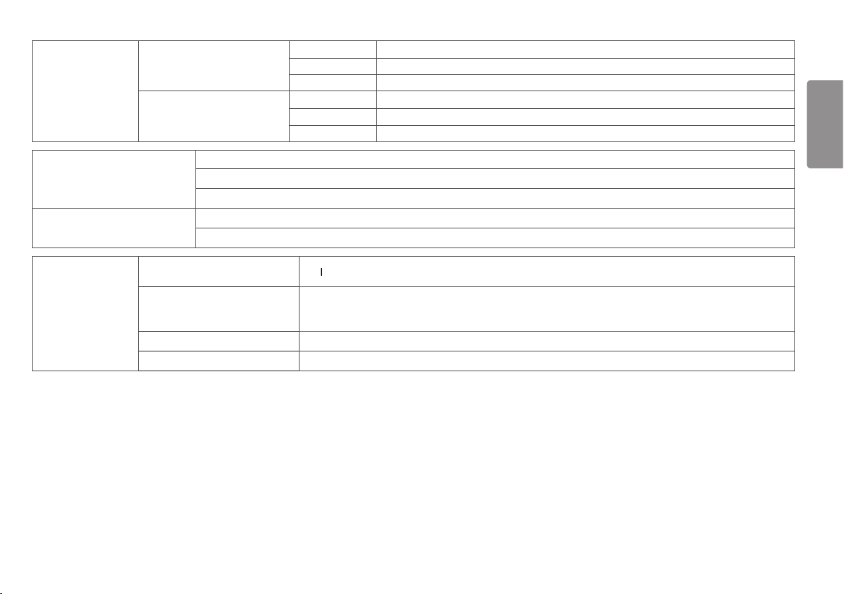
Medical Specifications
Classification by protection type against
Electric Shock
Class equipment
Classification according to the degree of
protection against ingress of water or
particulate matter
Front: IP35
Except for Front: IP32
Mode of operation Continuous Operation
Environment of Use This equipment is not suitable for use in the presence of flammable anesthetic or oxygen.
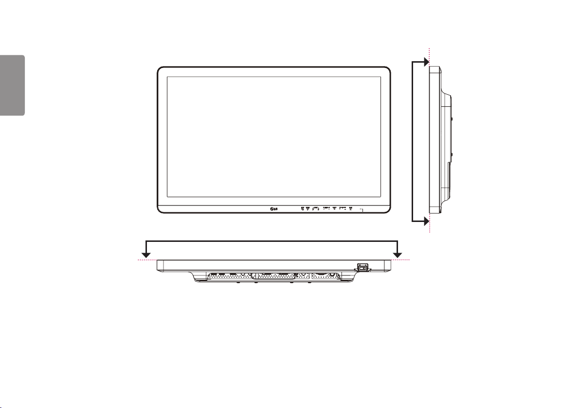
36
ENGLISH
IP35
IP35
37
ENGLISH
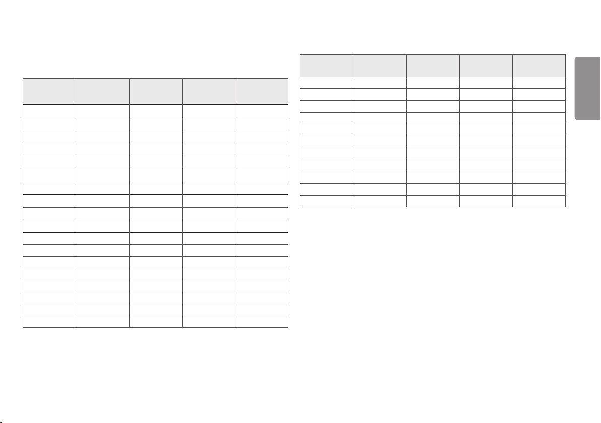
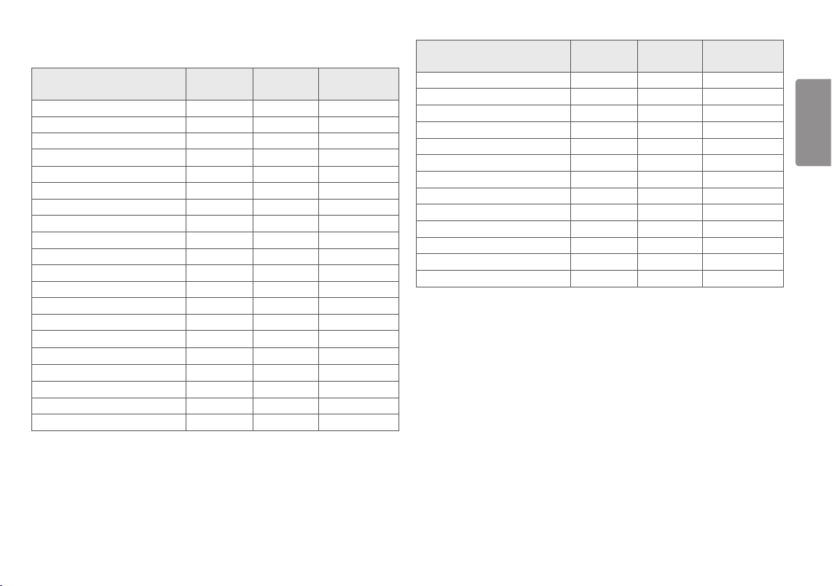
Preset Mode
D-SUB / DVI / HDMI
Preset Mode
Horizontal
Frequency (kHz)
Vertical
Frequency (Hz)
Polarity (H/V) Remarks
720 x 400 31.468 70.08 -/+
640 x 480 31.469 59.94 -/-
640 x 480 37.5 75 -/-
720 x 480 31.47 59.94 -/- HDMI only
800 x 600 37.879 60.317 +/+
800 x 600 46.875 75.0 +/+
1024 x 768 48.363 60.0 -/-
1024 x 768 60.023 75.029 +/+
1152 x 864 67.500 75.000 +/+
1280 x 720 45 60 +/+
1280 x 800 49.306 59.910 +/-
1280 x 1024 63.981 60.02 +/+
1280 x 1024 79.976 75.025 +/+
1400 x 1050 64.744 59.948 +/-
1440 x 900 55.469 59.901 +/-
1600 x 900 60.00 60.00 +/+
1680 x 1050 65.290 59.954 -/+
1920 x 1080 67.50 60 +/+
Input Timing (Video)
Vertical
dimensions
Vertical
Frequency (Hz)
HDMI SDI Remarks
480i 59.94/60 - O
480p 59.94/60 O -
576p 50 O -
576i 50 - O
720p 59.94/60 O O
720p 50 O O
1080i 59.94/60 - O
1080p 59.94/60 O O
1080i 50 - O
1080p 50 O O
1080p 29.97/30 O O
38
ENGLISH
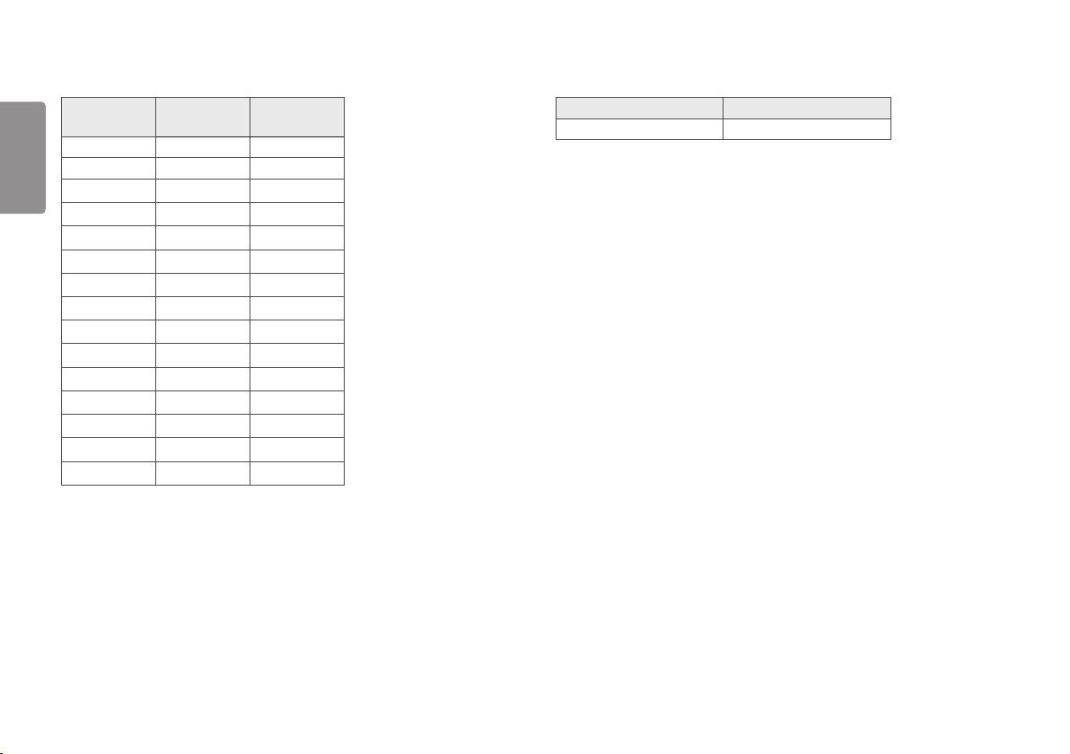
Input Timing (Component)
Resolution
Horizontal
Frequency (kHz)
Vertical
Frequency (Hz)
720 x 480 15.730 59.940
720 x 480 15.750 60.000
720 x 480 31.470 59.940
720 x 480 31.500 60.000
720 x 576 15.625 50.000
720 x 576 31.250 50.000
1280 x 720 44.960 59.940
1280 x 720 45.000 60.000
1280 x 720 37.500 50.000
1920 x 1080 33.720 59.940
1920 x 1080 33.750 60.000
1920 x 1080 28.125 50.000
1920 x 1080 56.250 50.000
1920 x 1080 67.432 59.940
1920 x 1080 67.500 60.000
Input Timing (S-Video, Composite)
• This monitor supports the NTSC, PAL.
Power indicator
Mode LED Color
On Mode Green
39
ENGLISH
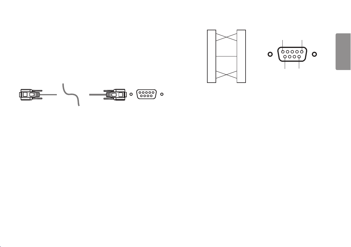
EXTERNAL CONTROLLER SETUP
The actual product may differ from the picture shown.
Connect the RS-232C (serial connector) of the PC to the RS-232C IN connector at the back of the monitor.
Purchase a cable to connect the RS-232C connectors, as the cable is not provided as an accessory.
Use an RS-232C cable to remotely control the monitor (see Figure 1).
RS-232C
(PC) (Monitor)
Figure 1: RS-232C Connection Diagram
PC Monitor
5 1
9
6
2
3
4
5
6
7
8
2
3
4
5
6
7
8
RXD
TXD
DTR
GND
DSR
RTS
CTS
RXD
TXD
DTR
GND
DSR
RTS
CTS
* There are no connections to Pin 1 and Pin 9.
40
ENGLISH
Set ID Function
This function allows you to assign a unique ID to the monitor to control it remotely from your PC.
Please refer to the "Transmission/Reception Protocol".
1 Press the button.
2 Use the , , , buttons to select [General]. Then press the button.
3 Use the , , , buttons to select [Set ID]. Then press the button.
4 Select a [Set ID] to assign. Then press the button. The [Set ID] can be a value from 1 to 10.
5 In order to exit from the OSD Menu, press the LED Control Button or press .
Communication Parameters
• Baud rate: 9600 bps (UART)
• Data length: 8 bits
• Parity bit: None
• Stop bit: 1 bit
• Communication code: ASCII code
• Crossed (reverse) cable used.
41
ENGLISH
Command Reference List
Command Command1 Command2
Data
(Hexadecimal)
01. Power k a 00 ~ 01
02. Screen Mute k d 00 ~ 01
03. Input select ([Main]) k b 00 ~ 06
04. Input select ([Sub]) k y 00 ~ 06
05. [Aspect Ratio] ([Main]) k c 00 ~ 02
06. [Aspect Ratio] ([Sub]) k o 00 ~ 01
07. [PBP / PIP] k n 00 ~ 05
08. [PIP Size] k p 00 ~ 02
09. [Main/Sub Screen Change] m a 01
10. [Picture Mode] d x 00 ~ 08
11. [Brightness] k h 00 ~ 64
12. [Contrast] k g 00 ~ 64
13. [Sharpness] k k 00 ~ 64
14. [Brightness Stabilization] m b 00 ~ 01
15. [SUPER RESOLUTION+] m c 00 ~ 03
16. [Black Level] m d 00 ~ 01
17. [DFC] m f 00 ~ 01
18. [Response Time] m g 00 ~ 03
19. [Black Stabilizer] m h 00 ~ 64
20. [Uniformity] m i 00 ~ 01
Command Command1 Command2
Data
(Hexadecimal)
21. [Gamma] m j 00 ~ 05
22. [Color Temp] k u 00 ~ 04
23. Red Gain j w 00 ~ 64
24. Green Gain j y 00 ~ 64
25. Blue Gain j z 00 ~ 64
26. [Language] f i 00 ~ 10
27. [SMART ENERGY SAVING] m k 00 ~ 02
28. [LED Control Button] m l 00 ~ 03
29. [DVI Power Supply] m m 00 ~ 01
30. [Auto Screen Off] m n 00 ~ 01
31. [OSD Lock] k m 00 ~ 01
32. [Reset] f k 00 ~ 02
33. [Auto Configuration] j u 01

42
ENGLISH
Transmission/Reception Protocol
Transmission
[Command1][Command2][ ][Set ID][ ][Data][Cr]
[Command 1]: j, k, m, x
[Command 2]: This command is used to control the monitor.
[Set ID]: Used to identify the monitor being controlled. [Set ID] can be assigned to each monitor under [General]
in the Settings Menu.
A value from 1 to 10 can be assigned. By selecting '0' for the [Set ID] value in the protocol format, you can
control all connected monitors.
* The value is displayed as base 10 on the OSD menu and used as base 16 (0x00 - 0x63) in the transmission/
reception protocol for remote control.
[Data]: Transmits a setting value (Data) required for the command described previously. (base 16)
When the Data ‘FF’ is sent, the setting value corresponding to the specific command is read (Data read mode).
[Cr]: Carriage return, which is ‘0x0D’ in ASCII code.
[ ]: Space, which is ‘0x20’ in ASCII code.
OK Acknowledgment
[Command2][ ][Set ID][ ][OK][Data][x]
When the Data has been successfully received, the monitor sends an ACK response signal in the above format. The
Data showing the current state is received in the Data read mode. The Data from the PC is simply returned in the
Data write mode.
Error Acknowledgment
[Command2][ ][Set ID][ ][NG][Data][x]
When the set receives an abnormal piece of Data for an unsupported function or there is a communication error, it
returns ACK in the format above.
Data 00 : Illegal code
Actual Data Structure (Base 16 Base 10)
• See the table below when inserting a base-16 value in [Data].
• The channel setup command (ma) uses a 2-byte base-16 value ([Data]) for channel number input.
00: Step 0 32: Step 50 (Set ID 50) FE: Step 254
01: Step 1 (Set ID 1) 33: Step 51 (Set ID 51) FF: Step 255
... ... ...
0A: Step 10 (Set ID 10) 63: Step 99 (Set ID 99) 01 00: Step 256
... ... ...
0F: Step 15 (Set ID 15) C7: Step 199 27 0E: Step 9998
10: Step 16 (Set ID 16) C8: Step 200 27 0F: Step 9999
... ... ...
* Commands may work differently depending on the model and signal.

43
ENGLISH
01. Power (Command: k a)
▶ Controls the On/Off of the power supply to the monitor.
Transmission [k][a][ ][Set ID][ ][Data][Cr]
Data 00: Power Off 01: Power On
Ack [a][ ][Set ID][ ][OK/NG][Data][x]
02. Screen Mute (Command: k d)
▶ Controls the On/Off of the screen of the monitor.
Transmission [k][d][ ][Set ID][ ][Data][Cr]
Data 00: Screen Mute Off 01: Screen Mute On
Ack [d][ ][Set ID][ ][OK/NG][Data][x]
03. Input select ([Main]) (Command: k b)
▶ Controls the input mode of the Main.
Transmission [k][b][ ][Set ID][ ][Data][Cr]
Data
00 : D-SUB 01 : SDI
02 : DVI 03 : HDMI
04 : Component 05 : Composite
06 : S-Video
Ack [b][ ][Set ID][ ][OK/NG][Data][x]
04. Input select ([Sub]) (Command: k y)
▶ Controls the input mode of the Sub.
Transmission [k][y][ ][Set ID][ ][Data][Cr]
Data
00 : D-SUB 01 : SDI
02 : DVI 03 : HDMI
04 : Component 05 : Composite
06 : S-Video
Ack [y][ ][Set ID][ ][OK/NG][Data][x]
05. [Aspect Ratio] ([Main]) (Command: k c)
▶ Adjusts the Aspect Ratio of the Main.
Transmission [k][c][ ][Set ID][ ][Data][Cr]
Data
00 : [Full Wide] 01 : [Original]
02 : [Just Scan]
Ack [c][ ][Set ID][ ][OK/NG][Data][x]

44
ENGLISH
06. [Aspect Ratio] ([Sub]) (Command: k o)
▶ Adjusts the Aspect Ratio of the Sub.
Transmission [k][o][ ][Set ID][ ][Data][Cr]
00 : [Full Wide] 01 : [Original]
Ack [o][ ][Set ID][ ][OK/NG][Data][x]
07. [PBP / PIP] (Command: k n)
▶ Controls the PBP/PIP mode.
Transmission [k][n][ ][Set ID][ ][Data][Cr]
Data
00 : Off 01: PBP
02: PIP_LT 03: PIP_RT
04: PIP_LB 05: PIP_RB
Ack [n][ ][Set ID][ ][OK/NG][Data][x]
08. [PIP Size] (Command: k p)
▶ Adjusts the size of PIP.
Transmission [k][p][ ][Set ID][ ][Data][Cr]
Data
00 : [Small] 01 : [Medium]
02 : [Large]
Ack [p][ ][Set ID][ ][OK/NG][Data][x]
09. [Main/Sub Screen Change] (Command: m a)
▶ Controls the Swap in the PBP mode.
Transmission [m][a][ ][Set ID][ ][Data][Cr]
Data 01 : Main/Sub Screen exchange
Ack [a][ ][Set ID][ ][OK/NG][Data][x]
10. [Picture Mode] (Command: d x)
▶ Controls the Picture Mode.
Transmission [d][x][ ][Set ID][ ][Data][Cr]
Data
00 : [Custom] 01 : [Mono]
02 : [sRGB] 03 : [EBU]
04 : [REC709] 05 : [SMPTE-C]
06 : [DICOM] 07 : [Calibration 1]
08 : [Calibration 2]
Ack [x][ ][Set ID][ ][OK/NG][Data][x]
11. [Brightness] (Command: k h)
▶ Adjusts screen brightness.
Transmission [k][h][ ][Set ID][ ][Data][Cr]
Data Min : 00 - Max : 64
Ack [h][ ][Set ID][ ][OK/NG][Data][x]

45
ENGLISH
12. [Contrast] (Command: k g)
▶ Adjusts the color contrast of the screen.
Transmission [k][g][ ][Set ID][ ][Data][Cr]
Data Min : 00 - Max : 64
Ack [g][ ][Set ID][ ][OK/NG][Data][x]
13. [Sharpness] (Command: k k)
▶ Adjusts the sharpness of the screen.
Transmission [k][k][ ][Set ID][ ][Data][Cr]
Data Min : 00 - Max : 64
Ack [k][ ][Set ID][ ][OK/NG][Data][x]
14. [Brightness Stabilization] (Command: m b)
▶ Controls the Brightness Stabilization function.
Transmission [m][b][ ][Set ID][ ][Data][Cr]
Data 00 : [Off] 01 : [On]
Ack [b][ ][Set ID][ ][OK/NG][Data][x]
15. [SUPER RESOLUTION+] (Command: m c)
▶ Controls the SUPER RESOLUTION+ function.
Transmission [m][c][ ][Set ID][ ][Data][Cr]
Data 00 : [High] 01 : [Middle]
02 : [Low] 03 : [Off]
Ack [c][ ][Set ID][ ][OK/NG][Data][x]
16. [Black Level] (Command: m d)
▶ Controls the Offset level. (HDMI only)
Transmission [m][d][ ][Set ID][ ][Data][Cr]
Data 00 : [High] 01 : [Low]
Ack [d][ ][Set ID][ ][OK/NG][Data][x]
17. [DFC] (Command: m f)
▶ Controls the DFC function.
Transmission [m][f][ ][Set ID][ ][Data][Cr]
Data 00 : [On] 01 : [Off]
Ack [f][ ][Set ID][ ][OK/NG][Data][x]

46
ENGLISH
18. [Response Time] (Command: m g)
▶ Controls the Response Time.
Transmission [m][g][ ][Set ID][ ][Data][Cr]
Data 00 : [Faster] 01 : [Fast]
02 : [Normal] 03 : [Off]
Ack [g][ ][Set ID][ ][OK/NG][Data][x]
19. [Black Stabilizer] (Command: m h)
▶ Controls the Black Sharpness Optimization function.
Transmission [m][h][ ][Set ID][ ][Data][Cr]
Data Min : 00 - Max : 64
Ack [h][ ][Set ID][ ][OK/NG][Data][x]
20. [Uniformity] (Command: m i)
▶ Controls the Uniformity function.
Transmission [m][i][ ][Set ID][ ][Data][Cr]
Data 00 : [On] 01 : [Off]
Ack [i][ ][Set ID][ ][OK/NG][Data][x]
21. [Gamma] (Command: m j)
▶ Adjusts the Gamma settings.
Transmission [m][j][ ][Set ID][ ][Data][Cr]
Data 00 : [Gamma 1.8] 01 : [Gamma 2.0]
02 : [Gamma 2.2] 03 : [Gamma 2.4]
04 : [Gamma 2.6] 05 : [DICOM Gamma Curve]
Ack [j][ ][Set ID][ ][OK/NG][Data][x]
22. [Color Temp] (Command: k u)
▶ Adjusts the color Temp.
Transmission [k][u][ ][Set ID][ ][Data][Cr]
Data
00 : [Custom] 01 : [6500K]
02 : [7500K] 03 : [9300K]
04 : [Manual]
Ack [u][ ][Set ID][ ][OK/NG][Data][x]
23. Red Gain (Command: j w)
▶ Adjusts the red.
Transmission [j][w][ ][Set ID][ ][Data][Cr]
Data Min : 00 - Max : 64
Ack [w][ ][Set ID][ ][OK/NG][Data][x]

47
ENGLISH
24. Green Gain (Command: j y)
▶ Adjusts the green.
Transmission [j][y][ ][Set ID][ ][Data][Cr]
Data Min : 00 - Max : 64
Ack [y][ ][Set ID][ ][OK/NG][Data][x]
25. Blue Gain (Command: j z)
▶ Adjusts the blue.
Transmission [j][z][ ][Set ID][ ][Data][Cr]
Data Min : 00 - Max : 64
Ack [z][ ][Set ID][ ][OK/NG][Data][x]
26. [Language] (Command: f i)
▶ Adjusts the language of the Menu screen.
Transmission [f][i][ ][Set ID][ ][Data][Cr]
English - Korean (17 languages)
Ack [i][ ][Set ID][ ][OK/NG][Data][x]
27. [SMART ENERGY SAVING] (Command: m k)
▶ Adjusts the SMART ENERGY SAVING.
Transmission [m][k][ ][Set ID][ ][Data][Cr]
Data 00 : [High] 01 : [Low]
02 : [Off]
Ack [k][ ][Set ID][ ][OK/NG][Data][x]
28. [LED Control Button] (Command: m l)
▶ Adjusts the LED ON time of the Control Button.
Transmission [m][l][ ][Set ID][ ][Data][Cr]
Data 00 : [Always On] 01 : [20Sec Time Out]
02 : [10Sec Time Out] 03 : [5Sec Time Out]
Ack [l][ ][Set ID][ ][OK/NG][Data][x]
29. [DVI Power Supply] (Command: m m)
▶ Controls the DVI Power Supply function.
Transmission [m][m][ ][Set ID][ ][Data][Cr]
Data 00 : [On] 01 : [Off]
Ack [m][ ][Set ID][ ][OK/NG][Data][x]

48
ENGLISH
30. [Auto Screen Off] (Command: m n)
▶ Adjusts the time to automatically turn the screen off when there is no monitor signal for a set period of time.
Transmission [m][n][ ][Set ID][ ][Data][Cr]
Data 00 : [On] 01 : [Off]
Ack [n][ ][Set ID][ ][OK/NG][Data][x]
31. [OSD Lock] (Command: k m)
▶ Controls the OSD Lock function.
Transmission [k][m][ ][Set ID][ ][Data][Cr]
Data 00 : [Off] 01 : [On]
Ack [m][ ][Set ID][ ][OK/NG][Data][x]
32. [Reset] (Command: f k)
▶ Controls the Reset operation.
Transmission [f][k][ ][Set ID][ ][Data][Cr]
Data
00: [Picture Reset] 01: Factory Reset
02: [User Preset Reset]
Ack [k][ ][Set ID][ ][OK/NG][Data][x]
33. [Auto Configuration] (Command: j u)
▶ Performs the Auto Configuration.
Transmission [j][u][ ][Set ID][ ][Data][Cr]
Data 01 : [Auto Configuration]
Ack [u][ ][Set ID][ ][OK/NG][Data][x]

WARNING: This equipment is compliant with Class A of CISPR 32. In a residential environment this equipment may
cause radio interference.
Read the user manual (CD) carefully and keep it at hand. The product label contains necessary information for after-
service.
Model
Serial No.
Supplier's Declaration of Conformity
Trade Name: LG
Responsible Party: LG Electronics USA, Inc.
Address: 1000 Sylvan Ave Englewood Cliffs, NJ 07632
Telephone: (201) 266-2215

