
ENGLISH
2
Please note that this information is for proper use and safety of the equipment. The following symbols may indicate a
hazardous situation in which, if not heeded, may result in serious injury or even death to the user or others, or damage
to the equipment.
WARNING
Indicates warning and safety instructions. If not adhered to, it could result in death or serious
injury to the user or others.
CAUTION
Indicates a hazardous situation which, if not heeded, may result in minor or moderate injury
to the user or others, or damage to the equipment.
For users in the United States
United State federal law restricts this equipment to be used by or on the order of a physician.
For users in other countries
This equipment is to be used by or on the order of a licensed person under the related laws for each country.
WARNING
To avoid the risk of electric shock, this equipment must only be connected to a supply mains with protective earth.
Do not modify this equipment without authorization of the manufacturer.
Intended use
This Medical Monitor is intended to provide color video displays and images from medical equipment which include
laparoscopy and endoscopy systems for surgery and various medical imaging systems. This product does not support
3D.
EC REP
Authorized representative in the European community.
LG Electronics European Shared Service Center B.V.
Krijgsman 1, 1186 DM Amstelveen, The Netherlands
Tel: +31-20-456-3132
LG Electronics Inc.
77, Sanho-daero, Gumi-si, Gyeongsangbuk-do, 39381, Republic of Korea
Tel: +82-1544-8777
ENGLISH
3
SAFETY INFORMATION
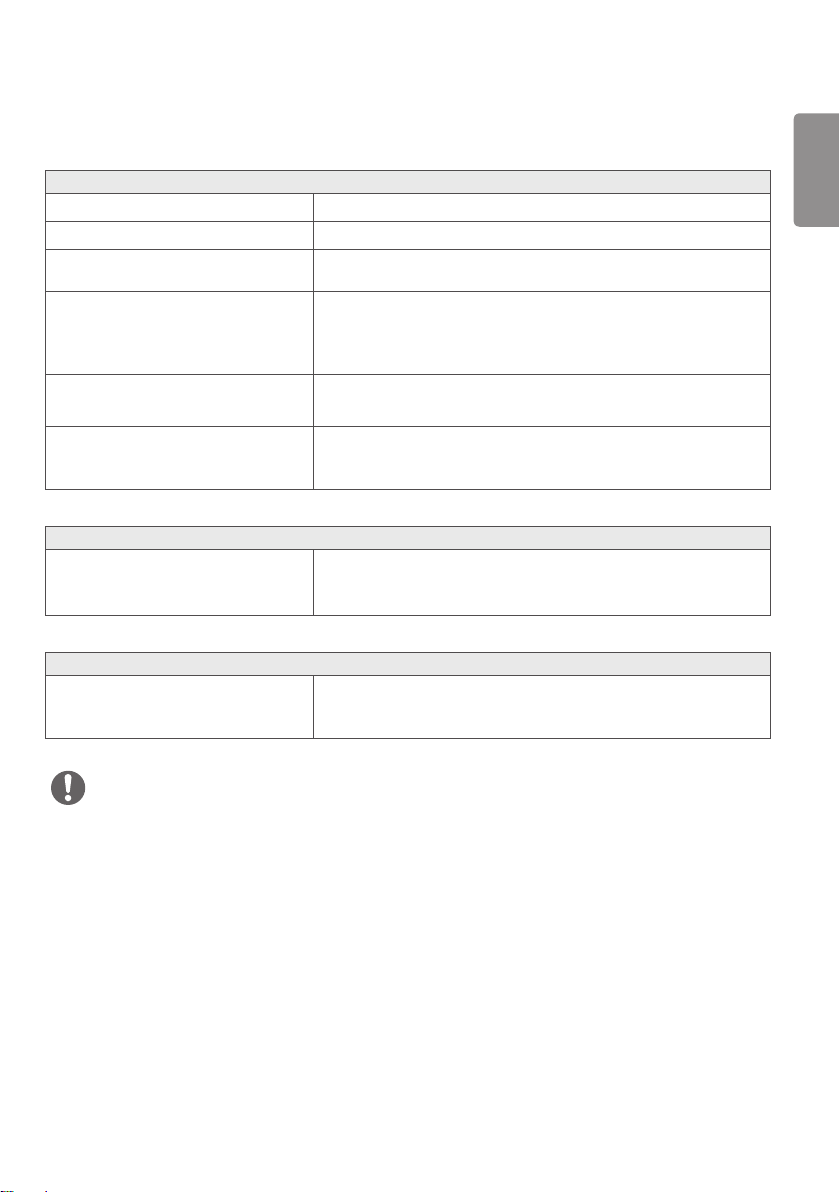
Safety Standard
Medical Device Classification
Classification by protection type against Electric
Shock
Class Ⅰ equipment
Classification according to the degree of protection
against ingress of water or particulate matter
Front: IP35
Except for Front: IP32
Mode of operation Continuous Operation
Environment of Use
This equipment is not suitable for use in the presence of
flammable anesthetic or oxygen.
Regulations
Safety and Electromagnetic Compatibility Information
This equipment has been tested and found to comply with the limits for medical devices in IEC 60601-1-2. These limits
are designed to provide reasonable protection against harmful interference in a typical medical installation.
This equipment generates, uses and can radiate radio frequency energy. If not installed and used in accordance with the
instructions, it may cause harmful interference to other devices in the vicinity.
However, there is no guarantee that interference will not occur in a particular installation. If this equipment does
cause harmful interference to other devices, which can be determined by turning the equipment off and on, the user is
encouraged to try to correct the interference by one or more of the following measures.
Reorient or relocate the equipment.
Increase the separation between the equipment.
Connect the equipment into an outlet on a circuit different from that to which the other devices are connected.
Contact manufacturer or authorized agent for help.
Radio Frequency compliance
FCC (For USA)
FCC NOTICE
This device complies with part 15 of the FCC Rules. Operation is subject to the following two conditions: (1) This device
may not cause harmful interference, and (2) this device must accept any interference received, including interference
that may cause undesired operation.
ENGLISH
4
FCC CAUTION
Changes or modifications not expressly approved by the party responsible for compliance could void the user’s authority
to operate the equipment. This transmitter must not be co-located or operated in conjunction with any other antenna
or transmitter.
FCC WARNING
This equipment may generate or use radio frequency energy changes or modifications to this equipment may cause
harmful interference unless the modifications are expressly approved in the instruction manual.
The user could lose the authority to operate this equipment if an unauthorized change or modification is made.
Note: This equipment has been tested and found to comply with the limits for a Class A digital device, pursuant to part
15 of the FCC Rules. These limits are designed to provide reasonable protection against harmful interference when the
equipment is operated in a commercial environment.
This equipment generates, uses, and can radiate radio frequency energy and, if not installed and used in accordance of
this equipment in a residential area is likely to cause harmful interference in which cause the user will be required to
correct the interference at his own expense.
For Europe
DECLARATION OF CONFORMITY
The complete Declaration of Conformity may be requested through the following postal address:
LG Electronics European Shared Service Center B.V., Krijgsman 1, 1186 DM Amstelveen, The Netherlands
or can be requested at our dedicated DoC website: http://www.lg.com/global/support/cedoc/cedoc#
Electro-Magnetic Compatibility Information
Electro-Magnetic Emissions
This EUT is intended for use in the electromagnetic environment specified below.
The customer or the user of the EUT should assure that it is used in such an environment.
Immunity Test Compliance Electromagnetic Environment – Guidance
RF Emissions CISPR 11 Group 1
The EUT uses RF energy only for its internal function.
Therefore, its RF emissions are very low and are not likely to cause
any interference in nearby electronic equipment.
RF Emissions CISPR 11 Class A
The EUT is suitable for use in all establishments, including domestic
establishments and those directly connected to the public low-
voltage power supply network that supplies buildings used for
domestic purposes.
Harmonic emissions IEC
61000-3-2
A
Voltage fluctuations/
Flicker emissions
IEC 61000-3-3
Complies

ENGLISH
5
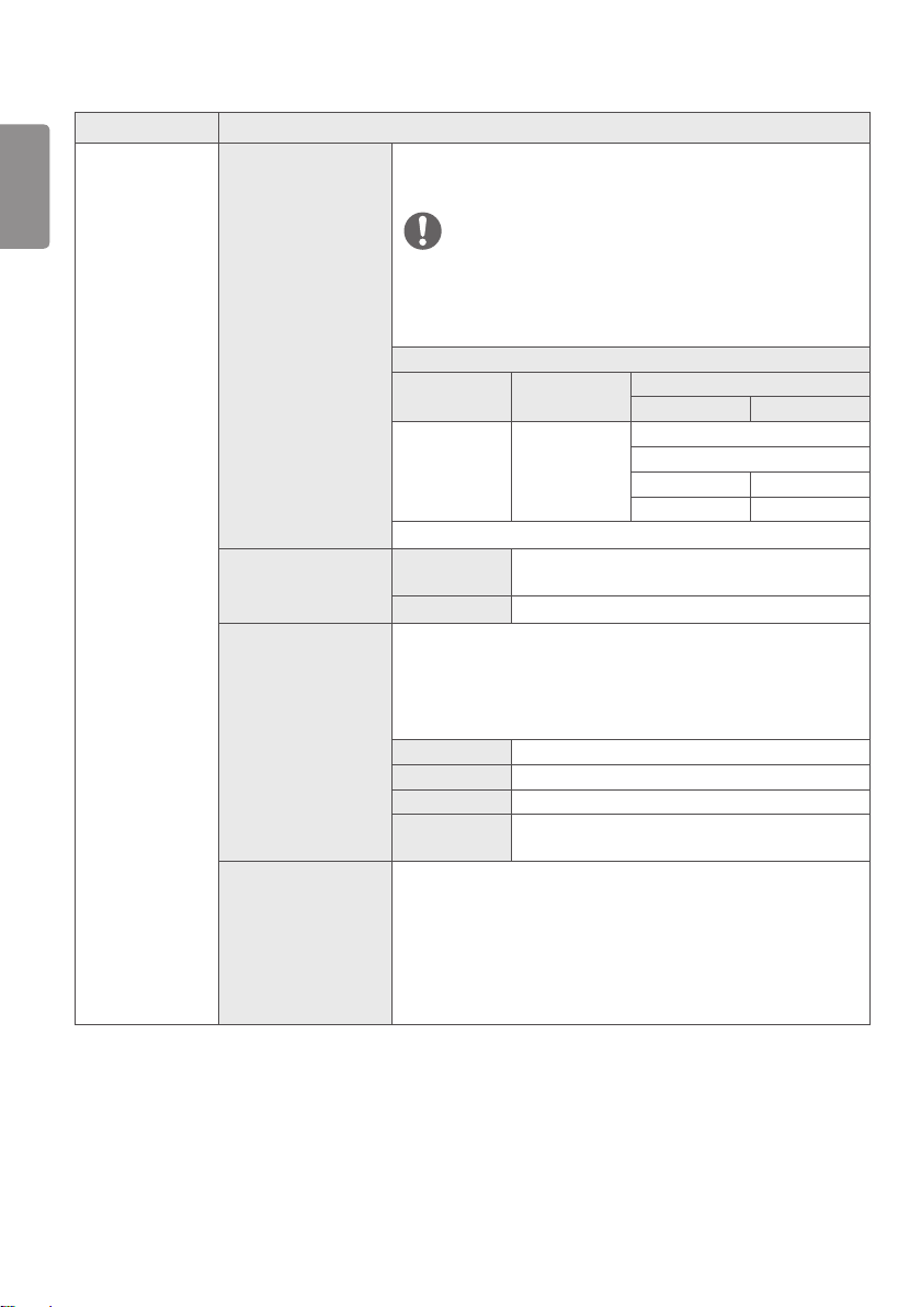
Electro-Magnetic Immunity
This EUT is intended for use in the electromagnetic environment specified below.
The customer or the user of the EUT should assure that it is used in such an environment.
Immunity Test
IEC 60601-1-2
Test Level
Compliance
Level
Electromagnetic Environment – Guidance
Electrostatic discharge
(ESD)
IEC 61000-4-2
± 8 kV contact
± 2 kV, ± 4 kV,
± 8 kV, ± 15 kV air
± 8 kV contact
± 15 kV air
Floors should be wood, concrete or ceramic
tile. If floors are covered with synthetic
material, the relative
humidity should be at least 30%.
Electrical fast transient/
burst
IEC 61000-4-4
± 2 kV
100 kHz repetition
frequency
± 2 kV
100 kHz repetition
frequency
Mains power quality should be that of a
typical commercial or hospital environment.
Surge Line-to-line
IEC 61000-4-5
± 0,5 kV, ± 1 kV ± 1 kV
Mains power quality should be that of a
typical commercial or hospital environment.
Surge Line-to-ground
IEC 61000-4-5
± 0,5 kV, ± 1 kV,
± 2 kV
± 2 kV
Voltage dips
IEC 61000-4-11
0 % U
T
; 0,5 cycle
At 0°, 45°, 90°, 135°,
180°, 225°, 270° and
315°
0 % U
T
; 0,5 cycle
At 0°, 45°, 90°, 135°,
180°, 225°, 270° and
315°
Mains power quality should be that of a
typical commercial or hospital environment.
If the user of the EUT image intensifier
requires continued operation during power
mains interruptions, it is recommended
that the EUT image intensifier be powered
from an uninterruptible power supply or a
battery.
0 % U
T
; 1 cycle
and
70 % U
T
; 25/30 cycles
Single phase: at 0°
0 % U
T
; 1 cycle
and
70 % U
T
; 25/30 cycles
Single phase: at 0°
Voltage interruptions
IEC 61000-4-11
0 % U
T
; 250/300 cycle 0 % U
T
; 250/300 cycle
RATED power frequency
magnetic fields
(50/60Hz)
IEC 61000-4-8
30 A/m 30 A/m Power frequency magnetic fields should
be at levels characteristic of a typical
location in a typical commercial or hospital
environment.
NOTE
U
T
is the A.C mains voltage prior to application of the test level.
ENGLISH
6
Immunity Test
IEC 60601-1-2
Test Level
Compliance
Level
Electromagnetic Environment – Guidance
Conducted
disturbances
induced by RF
fields
IEC 61000-4-6
3 V
0,15 MHz – 80 MHz
6 V in ISM bands
between 0,15 MHz
and 80 MHz
80 % AM at 1 kHz
3 V
0,15 MHz – 80 MHz
6 V in ISM bands
between 0,15 MHz
and 80 MHz
80 % AM at 1 kHz
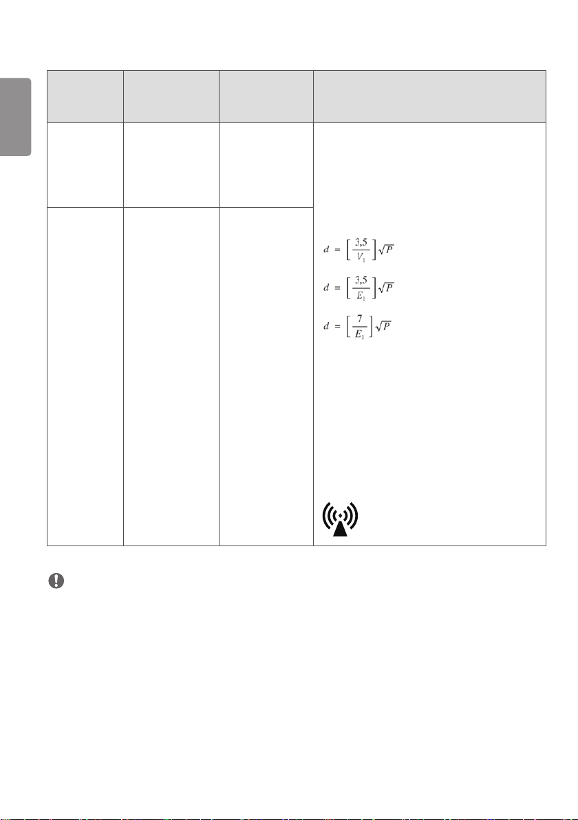
Portable and mobile RF communications equipment
should be used no closer to any part of the EUT,
including cables, than the recommended separation
distance calculated from the equation applicable to
the frequency of the transmitter.
Recommended separation distance:
Where P is the maximum output power rating of the
transmitter in watts(W) according to the transmitter
manufacturer and d is the recommended separation
distance in meters(M).
Field strengths from fixed RF transmitters as
determined by an electromagnetic site survey, should
be less than the compliance level in each frequency
range.
Interference may occur in the vicinity of equipment
marked with the following symbol:
Radiated RF EM
fields
IEC 61000-4-3
3 V/m
80 MHz – 2,7 GHz
80 % AM at 1 kHz
3 V/m
80 MHz – 2,7 GHz
80 % AM at 1 kHz
NOTE
At 80 MHz and 800 MHz, the higher frequency range applies.
These guidelines may not apply in all situations. Electromagnetic propagation is affected by absorption and reflection
from structures, objects and people.
1 Field strengths from fixed transmitters, such as base stations for radio (cellular/cordless) telephones and land
mobile radios, amateur radio, AM and FM radio broadcast and TV broadcast cannot be predicted theoretically with
accuracy. To assess the electromagnetic environment due to fixed RF transmitters, an electromagnetic site survey
should be considered. If the measured field strength in the location in which the EUT is used exceeds the applicable
RF compliance level above, the EUT should be observed to verify normal operation. If abnormal performance is
observed, additional measures may be necessary, such as re-orienting or relocating the EUT.
2 Over the frequency range 150 kHz to 80 MHz, field strengths should be less than [V1] V/m.
ENGLISH
7
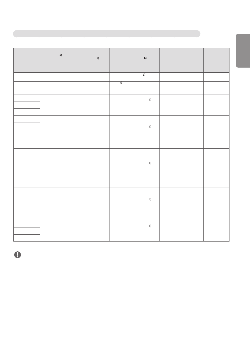
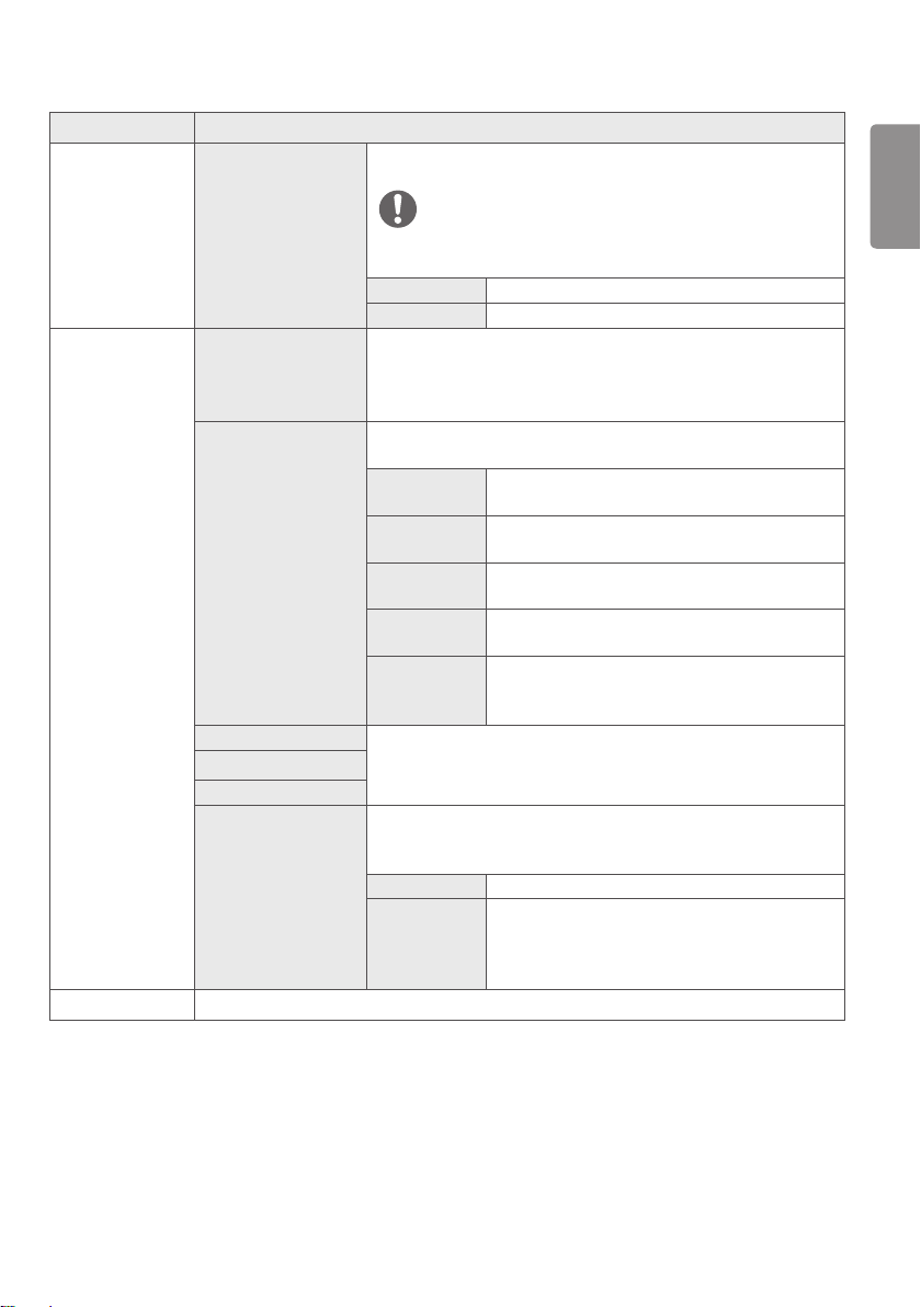
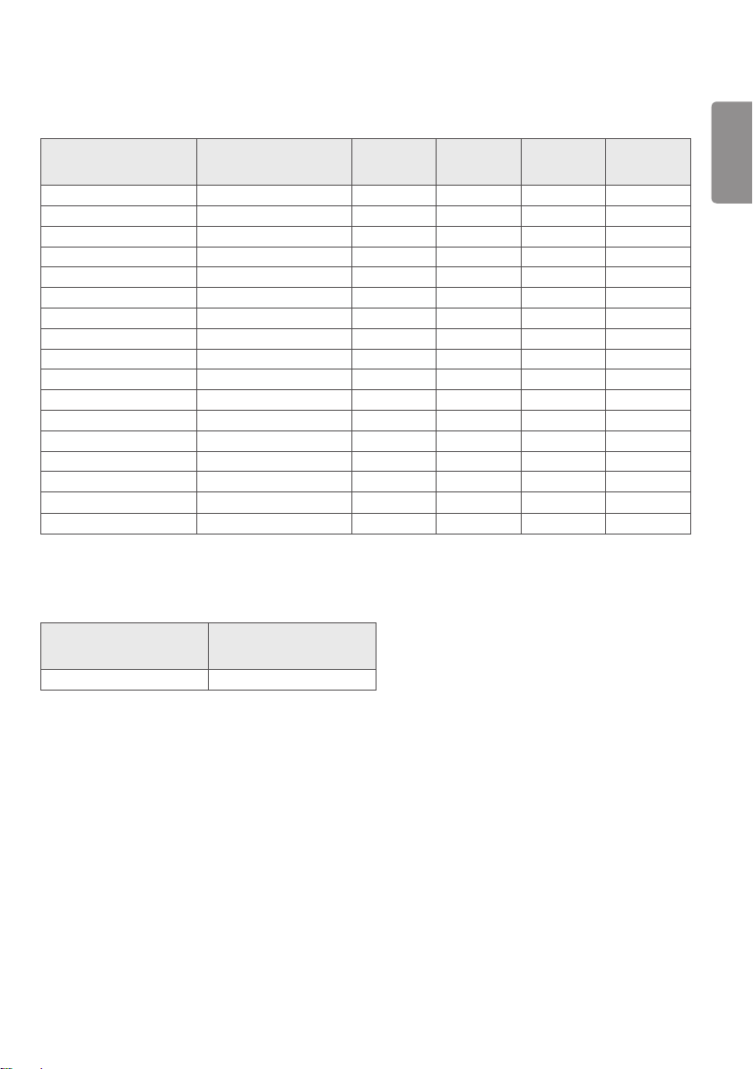
Test specifications for ENCLOSURE PORT IMMUNITY to RF wireless communications equipment
Test
frequency
(MHz)
Band
(MHz)
Service
Modulation
Maximum
power
(W)
Distance
(m)
IMMUNITY
TEST
LEVEL
(V/m)
385 380 –390 TETRA 400
Pulse modulation 18 Hz
1,8 0,3 27
450 430 – 470
GMRS 460,
FRS 460
FM ± 5 kHz deviation
1 kHz sine
2 0,3 28
710
704 – 787
LTE Band 13,
17
Pulse modulation
217 Hz
0,2 0,3 9
745
780
810
800 – 960
GSM 800/900,
TETRA 800,
iDEN 820,
CDMA 850,
LTE Band 5
Pulse modulation
18 Hz
2 0,3 28
870
930
1 720
1 700 – 1 990
GSM 1800;
CDMA 1900;
GSM 1900;
DECT;
LTE Band 1, 3,
4, 25; UMTS
Pulse modulation
217 Hz
2 0,3 28
1 845
1 970
2 450 2 400 – 2 570
Bluetooth,
WLAN,
802.11 b/g/n,
RFID 2450,
LTE Band 7
Pulse modulation
217 Hz
2 0,3 28
5 240
5 100 – 5 800
WLAN 802.11
a/n
Pulse modulation
217 Hz
0,2 0,3 95 500
5 785
NOTE
If necessary to achieve the IMMUNITY TEST LEVEL, the distance between the transmitting antenna and the ME
EQUIPMENT or ME SYSTEM may be reduced to 1 m. The 1 m test distance is permitted by IEC 61000-4-3.
a) For some services, only the uplink frequencies are included.
b) The carrier shall be modulated using a 50 % duty cycle square wave signal.
c) As an alternative to FM modulation, 50 % pulse modulation at 18 Hz may be used because while it does not
represent actual modulation, it would be worst case.
ENGLISH
8
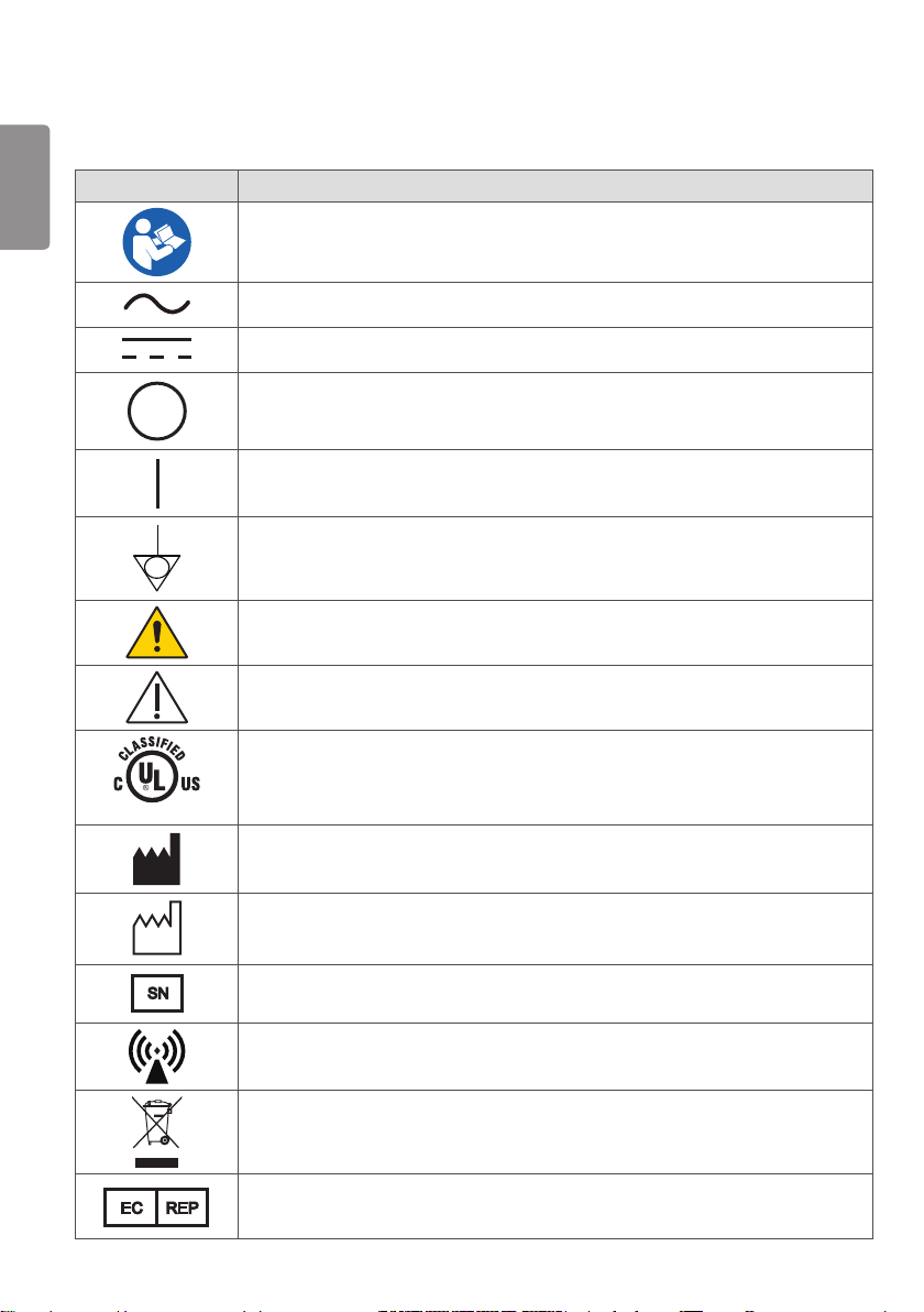
Symbols
Symbols Descriptions
Refer to instruction manual/ booklet
Alternate current
Direct current
Off (power: disconnect from the main switch)
On (power: connect from the main switch)
Potential Equalization Conductor
Warning
Caution
E486403
UL classified mark of medical equipment as to electrical shock, fire and mechanical hazards
only in accordance with ANSI/AAMI ES60601-1 (2005) + AMD 1 (2012), CAN/CSA-C22.2
No. 60601-1 (2014)
Manufacturer
Date of manufacture
SN
Serial number
Non-ionizing radiation
WEEE: Waste Electrical and Electronic Equipment
EC REP
Authorized representative in the European community.
ENGLISH
9
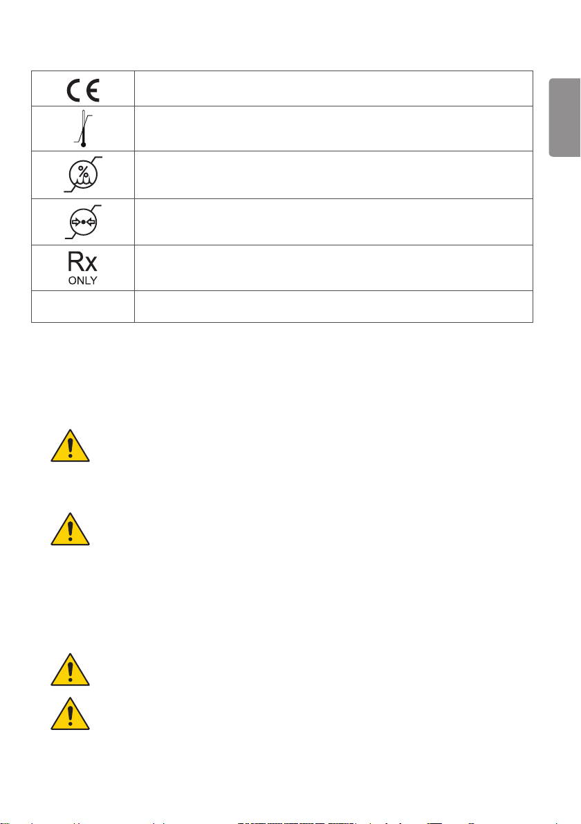
CE Marking
Temperature limit
Humidity limitation
Pressure limitation
For the customers in the U.S.A. Caution
Federal law (United States of America) restricts this device to sale by or on the order of a
licensed healthcare practitioner.
IPN1N2
Ingress of protection
Warning
WARNING: To avoid the risk of electric shock, this equipment must only be connected to a supply mains with
protective earth.
Connection
Do not connect the monitor with anything other than specified.
Otherwise, it may result in fire or electric shock.
To avoid the risk of electric shock, this monitor must only be connected to supply mains with
protective earth.
Handling
Always be sure to keep checking the condition of the system and the patient to ensure they are
normal during the use of the monitor. If any problem is found, take appropriate measures, such as
stopping the operation of the monitor, as required.
Never disassemble or modify the monitor as it may result in fire or electric shock.
Also, since the monitor incorporates parts that may cause electric shocks and other hazardous
parts, touching them may cause death or serious injury.
Do not hit or drop the monitor. The monitor may be damaged if it receives a strong jolt, which may
result in fire or electric shock if the monitor is used without being repaired.
The operator must not touch connectors of the monitor and the patient simultaneously.
The product has lower breaking capacity type. So do not install at the building power system
prospective short-circuit current exceeding 35 A.

ENGLISH
10
Caution
Do not install the ME Equipment in a location without easy disconnect accessibility.
Environment of Use and Storage
Do not install the monitor in a location with the conditions listed below.
Otherwise, it may result in failure or malfunction, cause fire or injury.
Close to facilities where water is used.
Where it will be exposed to direct sunlight.
Close to air-conditioner or ventilation equipment.
Close to heat source such as a heater.
Prone to vibration
Unsecure location place.
Dusty environment.
Saline or sulfurous environment.
High temperature or humidity.
Freezing or condensation.
Do not place the storage case in a location with the conditions listed below.
Where the cable of the monitor unit will be strongly pulled when the monitor is put into the
case, otherwise, the cable may be damaged, resulting in fire or electric shock.
Where someone might get their foot caught in the cable of the monitor.
Handling
For safety reasons, be sure to turn off the power when monitor is not used.
This monitor is contraindicated for pregnant woman.
MANUFACTURER will make available on request circuit diagrams, component part lists,
descriptions, calibration instructions, or other information that will assist SERVICE PERSONNEL to
repair those parts of ME EQUIPMENT.
Location of Cables
Make sure all cables are located so that they cannot be stepped on, tripped over, or otherwise
subjected to damage or stress.
If the monitor is defective, do not disassemble the monitor randomly. Maintenance of the monitor
should be done by a manufacturer.

ENGLISH
11
SAFETY PRECAUTIONS
The Safety Precautions are intended to prevent unexpected danger or harm by helping the user to use the product
safely and for its intended purpose.
WARNING
Failure to follow the instructions may result in serious injury or even death.
CAUTION
Failure to follow the instructions may result in minor injury to people or damage to the
product.
Precautions When Installing the Product
WARNING
Do not place the product close to heat sources such as radiators, fires, stoves, etc.
Be careful when disinfecting the product, as some disinfectants may cause fire.
Do not install the product in a damp or dusty area.
If the product emits smoke, strange odors or sounds, disconnect the power cord and contact the manufacturer.
Do not leave the power or signal cable, etc. in walkways.
Do not install the product onto a wall close to sources of oil or oil mist.
If the product has been dropped or its case is damaged, turn off the power and unplug the power cord from the
power outlet.
CAUTION
Ensure that the product is installed at least 100 mm (3.9 inches) away from the wall for good ventilation to prevent
deformation of the product or a fire due to the increase in the internal temperature.
Keep the product away from direct sunlight.
Do not install the product close to hot objects, such as lights.
Make sure the air vents are not blocked by a tablecloth or curtain.
Do not install the product near magnetic field generating equipment, such as transformers or high-voltage power
lines.
Installing the product in locations that do not meet the general conditions may seriously damage the product’s picture
quality, life cycle and appearance. Please check with our service engineer before installing in such locations.
Locations that do not meet the general conditions: places where the product is not intended for use, such as those
where fine dust or oil mist is generated, places where chemicals are used, places where the temperature is too high or
low, places where the humidity is too high, or places where the product is likely to be used for a long period of time (e.g.
airports or train stations).

ENGLISH
12
Precautions for the AC/DC Adaptor and Power
WARNING
If water or a foreign substance enters the product (power cord or AC/DC adaptor), disconnect the power cord
immediately and contact the manufacturer.
Always connect the power cord to a grounded outlet.
Do not touch the power plug or AC/DC adaptor with wet hands. If the pins of the plug are wet or dusty, clean and dry
them before use.
Insert the power plug securely so that it does not come loose. Do not use the product if the power outlet is loose.
Make sure the power cord is fully inserted into the AC/DC adaptor.
Do not insert any conductive objects into the device connection end of the power cord, while the power cord is
inserted into the wall outlet. Avoid touching the power plug immediately after pulling from the wall outlet.
Be sure to use the power cords and AC/DC adaptors provided or ones approved by LG Electronics, Inc.
Use the product at the rated voltage only.
Disconnect the power cable when not using the product for long periods.
Always pull by the plug when unplugging the power cord. Do not bend the power cord with excessive force.
Take care not to step on or place heavy objects (electronic appliances, clothing, etc.) on the power cord or AC/DC
adaptor. Be careful not to damage the power cord or AC/DC adaptor with sharp objects.
Never disassemble, repair or modify the power cord or AC/DC adaptor.
To turn off the main power, remove the power cord, which should be positioned so it is easy to access for operation.
If the product is connected to an AC wall outlet, it will not be disconnected from the AC power source even if you
turn off the switch.
CAUTION
Do not remove the power cord when the product is in use.
Be sure to keep the outlet, AC/DC adaptor and pins of the power plug clean from dust, etc.
Do not turn the monitor on or off by plugging in or unplugging the power plug from the power outlet. (Do not use the
power plug as a switch.)
Keep the power cord away from heating devices.
Precautions When Transporting the Product
WARNING
Before moving the product, disconnect the power cord and all other connected cables.
When carrying the product, make sure the screen faces forward and hold it firmly in both hands.

ENGLISH
13
CAUTION
Do not discard the delivery box with the original packaging. Put the product in the box when carrying.
When moving or unpacking the product, make sure that two or more people safely lift it because it is heavy. Using the
product after it has fallen may result in electric shock or fire. Contact the manufacturer.
Precautions When Using the Product
WARNING
Do not disassemble, repair or modify the product by yourself. If the product needs to be checked, reset or repaired,
contact the manufacturer.
Do not allow water to enter the product and keep the product dry at all times.
If there is a gas leak, do not touch the power outlet. Open the windows for ventilation.
Do not impact the front or sides of the screen with a hard object, such as a metal object. Do not scratch the screen.
If liquid or a foreign object falls into the product, switch the product off and unplug it from the wall outlet. Contact
the manufacturer.
Stop using the product if no image appears on the screen or no sound is heard. Switch the product off immediately.
Unplug the product from the power outlet and contact the manufacturer.
Do not use the product in any environment with excessively high temperatures or humidity.
Do not use high-voltage electrical products near the product. This may result in product malfunction due to electric
shock. (e.g. electrical mosquito swatter)
CAUTION
Do not use or store the product near inflammables.
Take a break to protect your health and vision when using the product for long periods of time.
Do not push hard against the screen surface or scratch it with your hands or sharp objects, such as a nail, pencil or
pen.
Keep the product clean.
Refer to the Owner's Manual and set the product to the correct resolution and frequency. Otherwise, you may
experience blurred vision.
Do not leave the product where it can get wet. Do not place anything containing liquid on top of the product, such as
a flower vase.
Because the LCD requires high technology consisting of hundreds of pixels, pixelated spots (red, green, white or
black) may appear on the screen during use. This is normal for an LCD screen and not an error, nor is it related to the
monitor's performance.
Given the nature of the viewing angle, the brightness and color of the LCD may vary between the left and right or top
and bottom, depending on the viewing position. This is normal for an LCD screen and not an error, nor is it related to
the monitor's performance.

ENGLISH
14
Precautions for Connecting to Other Medical Devices
Take the following precautions before using this product or connecting it to other medical devices.
Stop using this device for medical purposes if you experience interruptions or discomfort in executing medical
activities.
Quick movements, shaking and the focus of the video displayed on the monitor, its distance from the user, the user's
point of view, the user's physical fitness and other factors may cause discomfort (eye fatigue, dizziness, vomiting,
nausea, etc.).
Before using the product, check that the image of the connected device displays properly on the screen of this
product.
Precautions for Use with Electric Scalpels, etc.
When this product is used with electric scalpels, etc., the image may appear unstable, distorted or abnormal due to
the strong electromagnetic waves or voltage emitted by the device. This is not a malfunction.
If you are using this device with equipment that emits strong radio waves or voltage, install this device in a direction
that minimizes radio wave interference.
Recommendation for Using Multiple Units
Electronic products may fail unexpectedly. If using the monitor for medical, emergency or any other critical use, we
strongly recommend that you use multiple monitors or have a spare monitor ready.
Precautions When Cleaning the Product
The medical LCD monitor's front protective panel has been specially processed to reflect less light.
Using solvents such as thinner or benzene, acidic, alkaline or corrosive detergents, chemical cleaning fibers, etc. may
damage the finish material on the surface.
Unplug the power cord before cleaning.
Never spray water directly onto the monitor or use thinner or benzene solvents, acidic, alkaline or corrosive
detergents, or cleaning or sterilizing chemical cleaning fibers, etc. as they may damage the product.
To clean the product, unplug the power cord and wipe it gently with a soft cloth. Do not spray with water or wipe
with a wet cloth. When cleaning the product or the screen, do not use cleansers, automobile or industrial thinners,
abrasives or wax, benzene, alcohol, etc., as this may damage the product.
To clean the front frame, spray water onto a soft cloth two to four times and wipe in one direction only.
Do not rub the product with a stained cloth using more force than necessary. This may scratch the surface of the
product.
Do not allow the product to remain in contact with rubber or vinyl resin for extended periods. The surface finish may
deteriorate or the coating may peel off.
If you do not clean the product, dust will accumulate inside and may create a fire hazard or malfunction.

ENGLISH
15
Image Sticking Precautions
Displaying a still image for a prolonged period may damage the screen, resulting in image sticking. Most third-party
products have the same issue. Damage resulting from long-term static images is not covered by product warranty.
LICENSE
Each model has different licenses. Visit www.lg.com for more information on the license.
The terms HDMI and HDMI High-Definition Multimedia Interface, and the HDMI
logo are trademarks or registered trademarks of HDMI Licensing LLC in the United
States and other countries.
VESA, VESA logo, DisplayPort compliance logo and DisplayPort compliance logo for
dual-mode source devices are all registered trademarks of the Video Electronics
Standards Association.
The SuperSpeed USB Trident logo is a registered trademark of USB Implementers
Forum, Inc.

ENGLISH
16
PRODUCT SPECIFICATIONS
The product specifications are subject to change without prior notice for product improvements.
“ ~ ” refers to alternating current (AC), “ ” refers to direct current (DC).
LCD Screen Type TFT (Thin Film Transistor)
LCD (Liquid Crystal Display) Screen
Pixel Pitch 0.1554 mm x 0.1554 mm
Resolution Maximum resolution
3840 x 2160 @ 60 Hz
Recommended resolution
Video signal Horizontal frequency 30 kHz to 135 kHz
Vertical frequency 56 Hz to 61 Hz
Input Connectors Potential Equalization Conductor, SDI IN, DVI-D IN, HDMI IN, DP (DisplayPort) IN,
USB UP ( ), USB ( ), RS-232C
Output Connectors SDI OUT, DVI-D OUT, DP OUT
Power Source Power Rating 19 V 6.32 A
Power consumption Max 120 W
AC/DC Adaptor DA-120D19 type, manufactured by Asian Power Devices Inc. (APD)
Input: 100-240 V~ 50-60 Hz, 1.8-0.7 A
Output: 19 V 6.32 A
Class I
Environmental
Conditions
Operating Conditions Temperature 0 °C to 40 °C (32 °F to 104 °F)
Humidity 0 % to 80 %
Pressure 700 hPa to 1060 hPa
Storing Conditions Temperature -20 °C to 60 °C (-4 °F to 140 °F)
Humidity 0 % to 85 %
Pressure 500 hPa to 1060 hPa
Dimensions Monitor Size (Width x Height x Depth)
654.4 x 410.9 x 58 (mm)
25.7 x 16.1 x 2.2 (inches)
Weight (without packaging) 7.7 kg (16.9 lbs)
ENGLISH
17
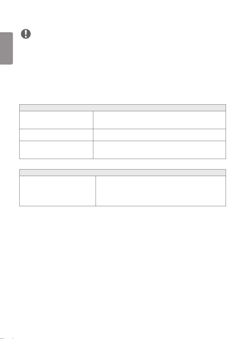
Medical Specifications
Prevention of electric shock
Class Ⅰ
Classification according to the
degree of protection against
ingress of water or particulate
matter
Front: IP35
Except for Front: IP32
Level of safety in places where
flammable anesthetics are mixed
with air, oxygen or nitrogen oxides
Not suitable for use in places where flammable
anesthetics are mixed with air, oxygen or nitrogen
oxides.
Operating mode Continuous
IP35
IP35


ENGLISH
19
ON CLEANING
Recommended Cleaning Chemicals
Isopropanol 100%
Ethanol 70%
Cidex® OPA
0.9% NaCl solution
How to Use Cleaner
Prior to cleaning, turn off the monitor and remove the power cable.
Soak a soft cloth in a recommended cleaner, then lightly rub the screen with no more than 1 N of force.
The cleaner could cause serious damage if it leaks inside the monitor while cleaning.
Do not clean the screen’s LCD panel as it may be damaged. Clean the other parts of the monitor.
Do not use benzene, thinner, acids or alkaline cleaners or other such solvents.
Cleaning guidelines for displays must only be carried out by medical professionals (doctors or nurses) and must not
be handled by patients.
ENGLISH
20
ASSEMBLY AND PREPARING
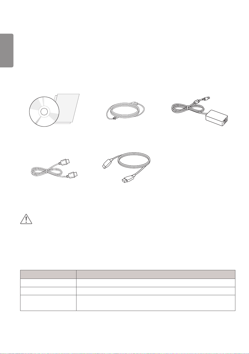
Product Composition
Please check whether all the components are included in the box before using the product. If there are any missing
components, contact the retailer where you purchased the product. Note that the product and related components
may look different from those shown here.
CD (Software/Owner's Manual)/
Regulatory Manual/Cards
Power Cord AC/DC Adaptor
DisplayPort Cable
HDMI Cable
CAUTION
Always use genuine LG components to ensure safety and product performance.
The product warranty will not cover damage or injury caused by the use of unauthorized components.
It is recommend that use the supplied components.
If you use generic cables not certified by LG, the screen may not display or there may be image noises.
Need to use the authorized components about the below accessories. Unauthorized components may be cause of the
damage and malfunction of the product.
Component Standard
HDMI Cable Support HDMI 2.0 version, UL, Impedance 100ohm
DisplayPort Cable Support DISPLAYPORT 1.2a version, UL, Impedance 100ohm
Power Cord US – Approved Medical grade regulation
Others – Approved country safety regulation
The AC/DC adaptors and etc. except the upper components need to be used only supplied by manufacturer.

ENGLISH
21
NOTE
The components may look different from those illustrated here.
Without prior notice, all product information and specifications contained in this manual are subject to change to
improve the performance of the product.
To purchase optional accessories, visit an electronics store or an online shopping site, or contact the retailer from
which you purchased the product.
The power cord provided may differ depending upon the region.
Supported Drivers and Software
Check the drivers and software supported by your product and refer to the manuals on the CD enclosed in the product
package.
Drivers and Software Installation Priority 27HJ713S
Monitor Driver Recommended O
True Color Pro Optional O
Required and Recommended: You can download and install the latest version from the enclosed CD or from the LGE
website (www.lg.com).
Optional: You can download and install the latest version from the LGE website (www.lg.com).
ENGLISH
22
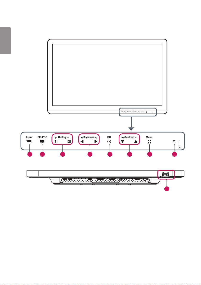
Product and LED Control buttons
9
1 2 5 7 8 3 6 4
ENGLISH
23
LED Control button Functions
1
Input Selects the input mode.
2
PIP/PBP Displays the screens of two input modes on one monitor.
3
Hotkey 1, 2 Opens the Hotkey Settings menu.
4
Brightness Adjusts the screen brightness.
5
OK Selects menus or options and confirms.
6
Contrast Adjusts the screen contrast.
7
Menu Displays LED Control buttons on the front panel and opens the menu mode.
8
Power
indicator
The green indicator illuminates if the power is on. The arrow indicates the position of the
power switch.
9
Power switch Turns the power on/off.
NOTE
The Power button is located at the bottom right on the front of the monitor.
If the Control Key LED is turned off, press the Control Key [Menu] button to turn the Control button LED on. When
the Control Key LED is turned on, you can control the Control Key functions.
ENGLISH
24
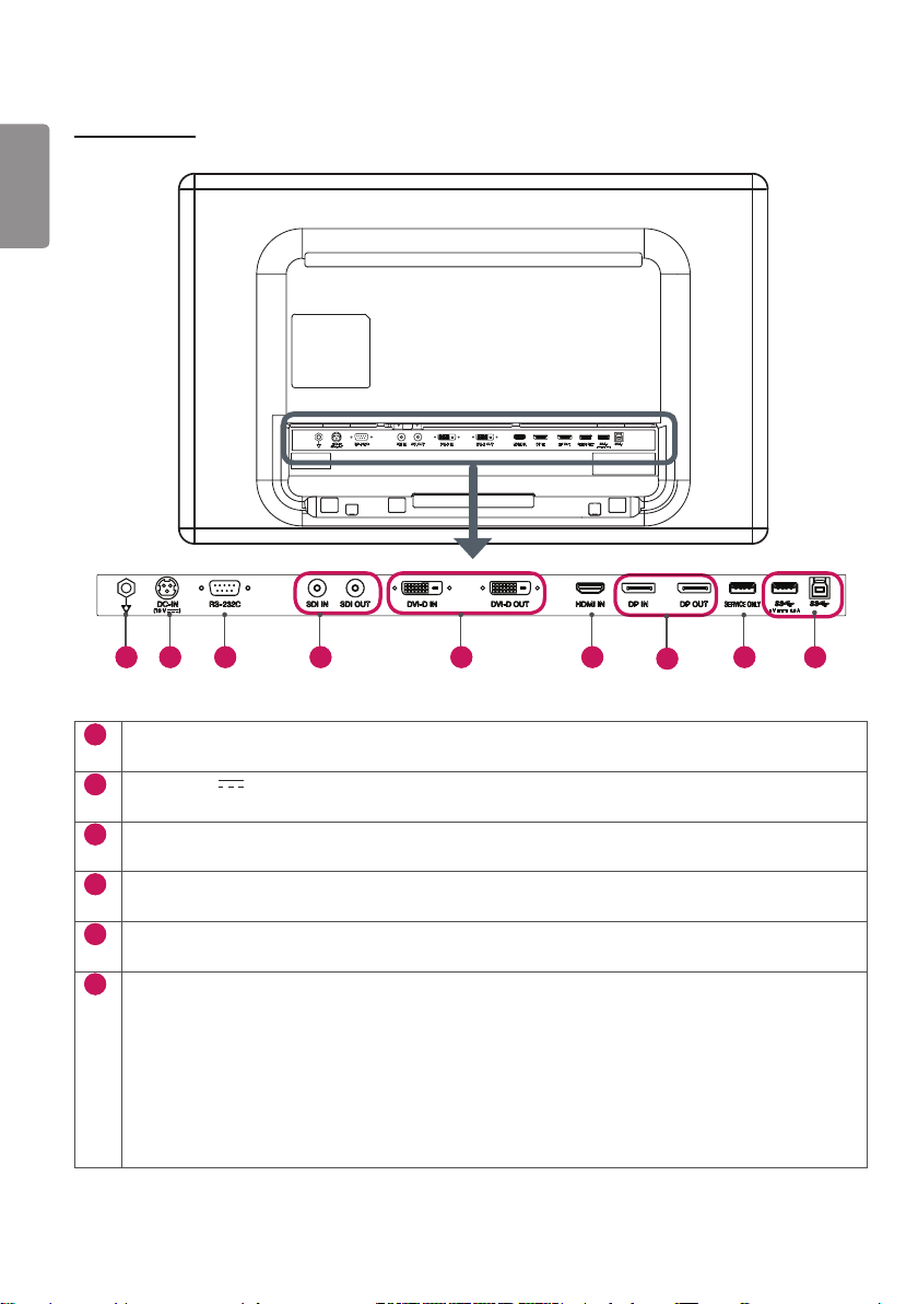
Connectors
1 2 3 4 5 6
7
9 8
1
Potential Equalization Conductor
- Connect an equipotential plug.
2
DC-IN (19 V ) Connector
- Connect the AC/DC adaptor.
3
RS-232C Connector
- Connect to an external device through the RS-232C connector and control the monitor.
4
SDI IN / SDI OUT Connector
- Receives or transmits serial digital component signals.
5
DVI-D IN / DVI-D OUT Connector
- Receives or transmits digital video signals.
6
HDMI IN Connector
- Receives digital video signals.
- DVI to HDMI/DP (DisplayPort) to HDMI cables may cause compatibility issues.
Make sure to use certified cables that bear the HDMI logo. If you do not use a certified HDMI cable, the
screen may not display, or a connection error may occur.
►Recommended HDMI cable types
- High-speed HDMI
®
/
TM
cables
- High-speed HDMI
®
/
TM
Ethernet cables
ENGLISH
25
7
DP IN / DP OUT Connector
- Receives or transmits digital video signals.
- There may be no video output depending on the DP (DisplayPort) version of your PC.
- A cable with DisplayPort 1.2 specifications is recommended when using a Mini DP to DP (Mini DisplayPort
to DisplayPort) cable.
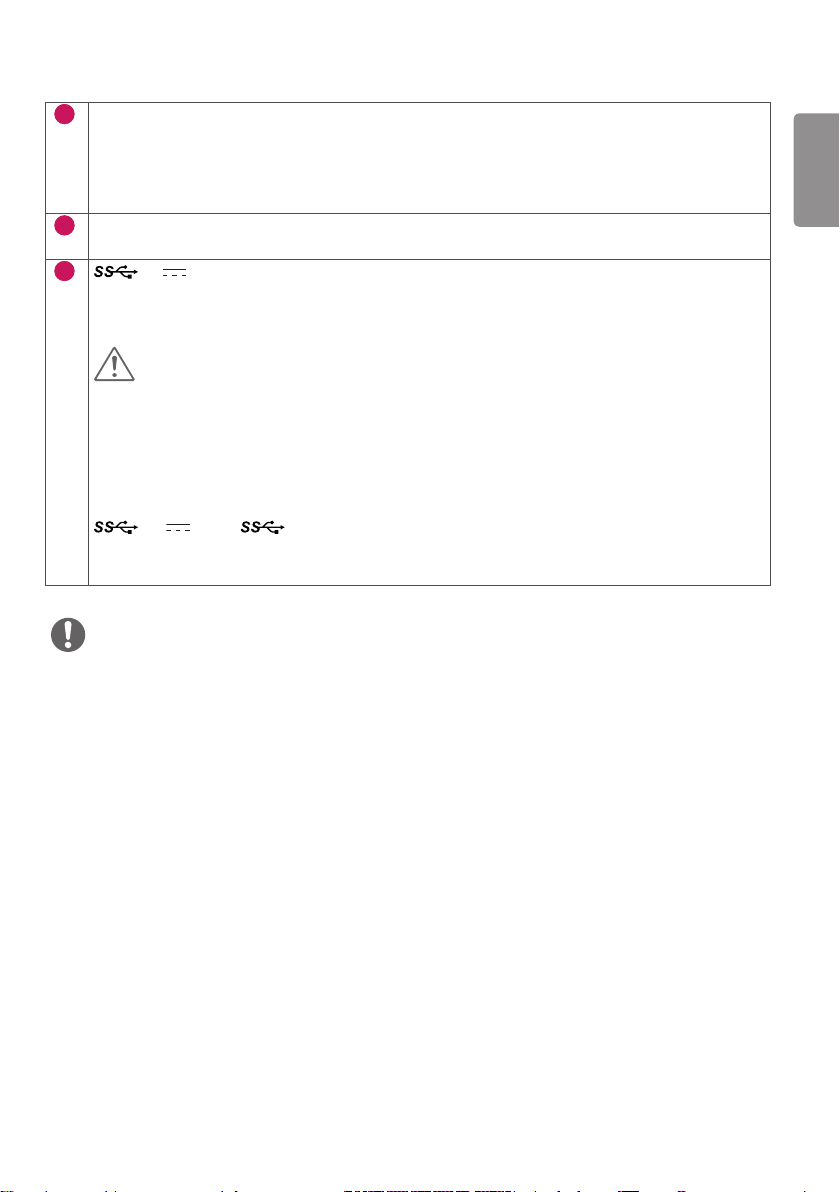
8
SERVICE ONLY Connector
- The USB port is used for service only.
9
5 V 0.9 A (USB Connector)
- Used for HW Calibrator (Optional Accessory) connection.
- A keyboard, mouse or USB device can be connected.
CAUTION
Precautions for Using USB Storage Devices
A USB storage device installed using an automatic recognition program or its own driver may not be
recognizable.
Some USB devices may not be supported or may not work properly.
It is recommended that you use a USB hub or hard disk drive with power supplied. (If insufficient power is
supplied, the USB storage device may not be detected properly)
5 V 0.9 A / (USB Connector)
- Connect your accessory to the USB input port.
- To use USB 3.0, connect a USB 3.0 Type A-B cable to your PC.
NOTE
All signal OUT connectors (SDI, DVI, DP) output signals when the monitor's power switch is on. Signals are not output
when the power switch is off.
This monitor supports the *Plug and Play feature.
* Plug and Play: A feature that allows you to add a device to your computer without having to reconfigure anything or
install any manual drivers.
The standard of the DVI and the SDI output terminals for transmitting a screen
- DVI OUT: Connect a 5-meter cable to transmit a copied screen to a monitor.
- SDI OUT: Connect a 100-meter cable (BELDEN 1694) to transmit a copied screen to a monitor.

ENGLISH
26
Installing the Monitor
Cable connection and organize
Before connecting the connectors, remove the back
door as shown below.
1 Remove the back door by lifting it in the direction
of the arrow.
The back door is held in place with a magnet.
2 After installing the cables, tidy them up using the
cable holders.
3 After tidying the cables, attach the back door and
use the product.
CAUTION
When the back door is attached to the monitor, the
monitor meets water resistance standards. Do not
use the monitor with the back door detached, as the
water resistance capability is not guaranteed without
the door.

ENGLISH
27
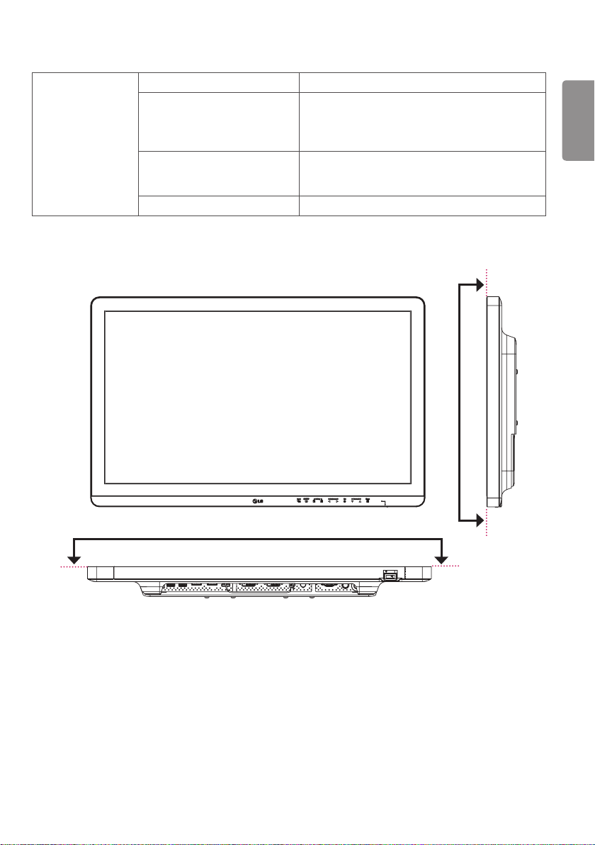
Installing on the Wall
Install the monitor at least 100 mm (3.9 inches) away
from the wall on each side of the monitor to ensure
sufficient ventilation. Detailed installation instructions
can be obtained from your local dealer. Please refer to
the manual to install and set up a tilting wall mounting
bracket.
100 mm
(3.9 inches)
100 mm
(3.9 inches)
100 mm
(3.9 inches)
100 mm
(3.9 inches)
To install the monitor to a wall, attach a wall mount
plate (optional) to the back of the monitor.
Make sure that the wall mount plate (optional) is
securely fixed to the monitor and to the wall.
1 Using screws longer than the standard length may
damage the inside of the product.
2 A non-VESA standard screw may damage
the product and cause the monitor to fall. LG
Electronics is not liable for any accidents relating to
the use of non-standard screws.
Wall Mount (mm)
100 x 100 200 x 100
Standard screw
M4 x L10 M4 x L10
Required screws
4 4
Wall Mount Plate
(optional)
RW120 RW240
NOTE
The screws (M4 x L10) can be found fastened in the
wall mount screw holes on the back of the monitor.
Use the screws specified by VESA standards.
The wall mount kit includes an installation manual and
the necessary parts.
The wall mount plate is an optional item. You can
obtain additional accessories from your local dealer.
The length of screws may differ depending on the wall
mount. Be sure to use the proper length.
For more information, please refer to the manual for
the wall mounting bracket.
ENGLISH
28
CAUTION
Disconnect the power cord first. Then move or install
the monitor. There is risk of electric shock.
Installing the monitor on the ceiling or on a slanted wall
may result in the monitor falling off, which could lead to
injury. Use an authorized LG wall mount and contact the
local dealer or qualified personnel.
Applying excessive force when tightening screws may
damage the monitor. Such damage is not covered by
the product warranty.
Use the wall mounting bracket and screws that confirm
to VESA standards. Damage caused by the use or
misuse of inappropriate components is not covered by
the product warranty.
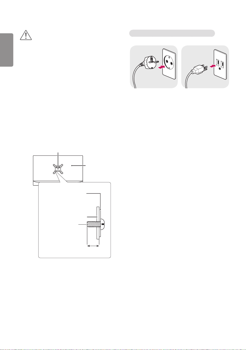
When measured from the back of the monitor, the
length of each installed screw must be 8 mm (0.3
inches) or less.
Wall mount plate
Back of the
monitor
Screw
specifications
: M4 x L10
Wall mount plate
Back of the monitor
Max. 8 mm
(0.3 inches)
Precautions for Connecting the Power Cord
100-240 V ~
Make sure to use the power cord that is provided in
the product package. Connect the cord to a grounded
power outlet.
If you need another power cord, please contact your
local dealer or the nearest retail store.
ENGLISH
29
SETTINGS
Activate Main Menu
1 Press the [Menu] button to activate the LED Control button. Pressing the [Menu] button while the LED Control
button is activated brings up the OSD menu.
2 Use the [ Brightness ] left/right and [ Contrast ] up/down LED Control buttons to navigate.
3 Press the [Menu] or [ Brightness] LED Control button to exit the OSD menu.
CAUTION
• The actual On Screen Displays (OSDs) that appear on your monitor may differ from those shown in this manual.
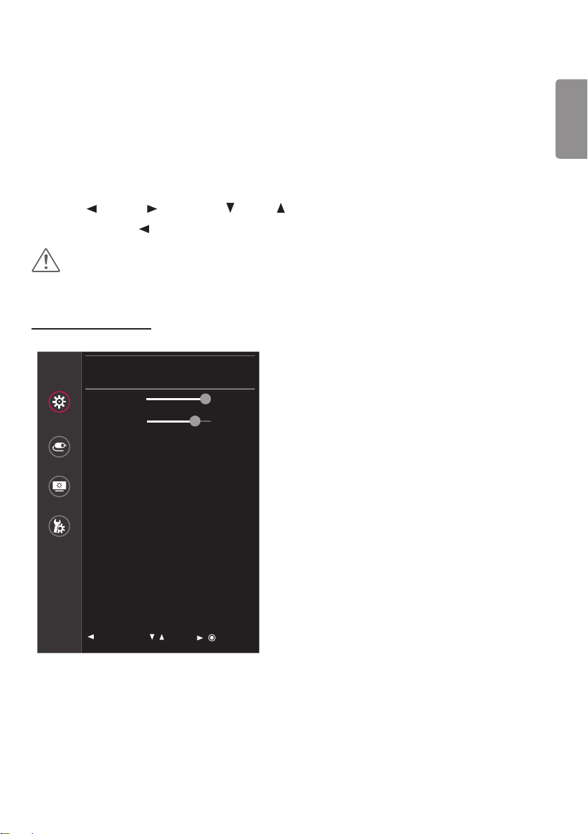
QUICK SETTINGS
Quick Settings
Quick Settings
Brightness 100 >
Contrast 70 >
Input
Hot key Settings >
User Preset >
Picture
General
: Exit
/ : Move
/ : Ok

ENGLISH
30
The following settings are available.
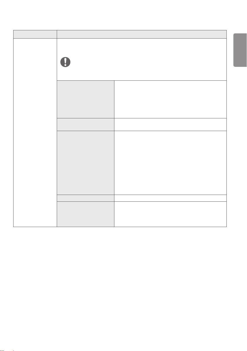
Quick Settings Description
Brightness
Adjusts the brightness of the screen.
NOTE
You can turn the Brightness Stabilization to On/ Off by pressing the button in the
Brightness menu.
When the Brightness Stabilization is On, Brightness menus becomes disabled.
When the Brightness Stabilization is On, SMART ENERGY SAVING and DFC menus
become disabled.
Contrast
Adjusts the color contrast of the screen.
Hot key Settings Assigns hotkeys for picture settings. Once configured, the assigned menu is activated when
a hotkey is pressed. (PIP Size, Mono, Color Temp, Gamma, Black Stabilizer, Screen Zoom,
Off)
Hotkey 1 Assigns a function to Hotkey 1.
Hotkey 2 Assigns a function to Hotkey 2.
ENGLISH
31
Quick Settings Description
User Preset User Preset allows the user to save or load up to 10 picture quality settings for multiple
connected devices in each preset.
NOTE
You can use User Preset to import or save items in Picture Adjust and Color Adjust of the
Picture menu.
User Name Allows the user to change and register a user name (Preset
1 ~ Preset 3, User 1 ~ User 7) as the user wants.
The user can enter a user name to be registered by using the
screen keyboard.
Preset 1 ~ Preset 3 are factory-set user names as samples
and the user can change the names.
Load User Settings Allows the user to change the picture quality settings by
loading the User Preset settings.
Save User Settings Saves the current picture quality settings in the
corresponding User Preset.
Preset 1 ~ Preset 3 are factory-set values as samples and
the user can change the values.
Preset 1: Use this preset for bluish color.
Preset 2: Use this preset for greenish color and brighter
low-gradation.
Preset 3: Use this preset to soften the red tone.
User 1 ~ User 7: Initial values are the same as the factory
settings.
Default User Settings Loads the initial basic picture settings.
User Preset Reset Initializes User Preset settings.
Initializes the existing user name and user settings to be
restored to factory settings (Preset 1 ~ Preset 3, User 1
~ User 7).
ENGLISH
32
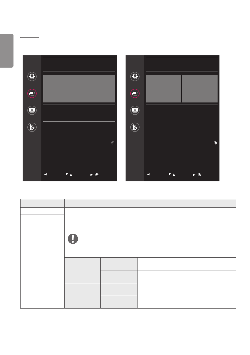
INPUT
<Default screen> <Main screen and sub screen>
Input
Quick Settings
DisplayPort
Input
Picture
Main Input List DisplayPort >
Aspect Ratio Full Wide >
General
PBP / PIP >
PIP Size Small >
Main/Sub Screen Change
: Exit
/ : Move
/ : Ok
Input
Quick Settings
DisplayPort
MAIN
DVI-D
Input
Picture
Input List >
Aspect ratio >
General
PBP / PIP >
PIP Size Small >
Main/Sub Screen Change
: Exit
/ : Move
/ : Ok
The following settings are available.
Input Description
Main Input List
Selects the input mode.
Input List
Aspect Ratio Adjusts the aspect ratio of the screen. (Full Wide, Original, 1:1)
NOTE
The display may look the same for Full Wide, Original, and 1:1 options at the
recommended resolution (3840 x 2160).
Main Aspect
Ratio
Full Wide Displays the video to fit the PBP / PIP screen,
regardless of the video signal input.
Original Displays the video in the aspect ratio of the video
signal input on the PBP / PIP screen.
Sub Aspect
Ratio
Full Wide Displays the video to fit the PBP / PIP screen,
regardless of the video signal input.
Original Displays the video in the aspect ratio of the video
signal input on the PBP / PIP screen.
ENGLISH
33
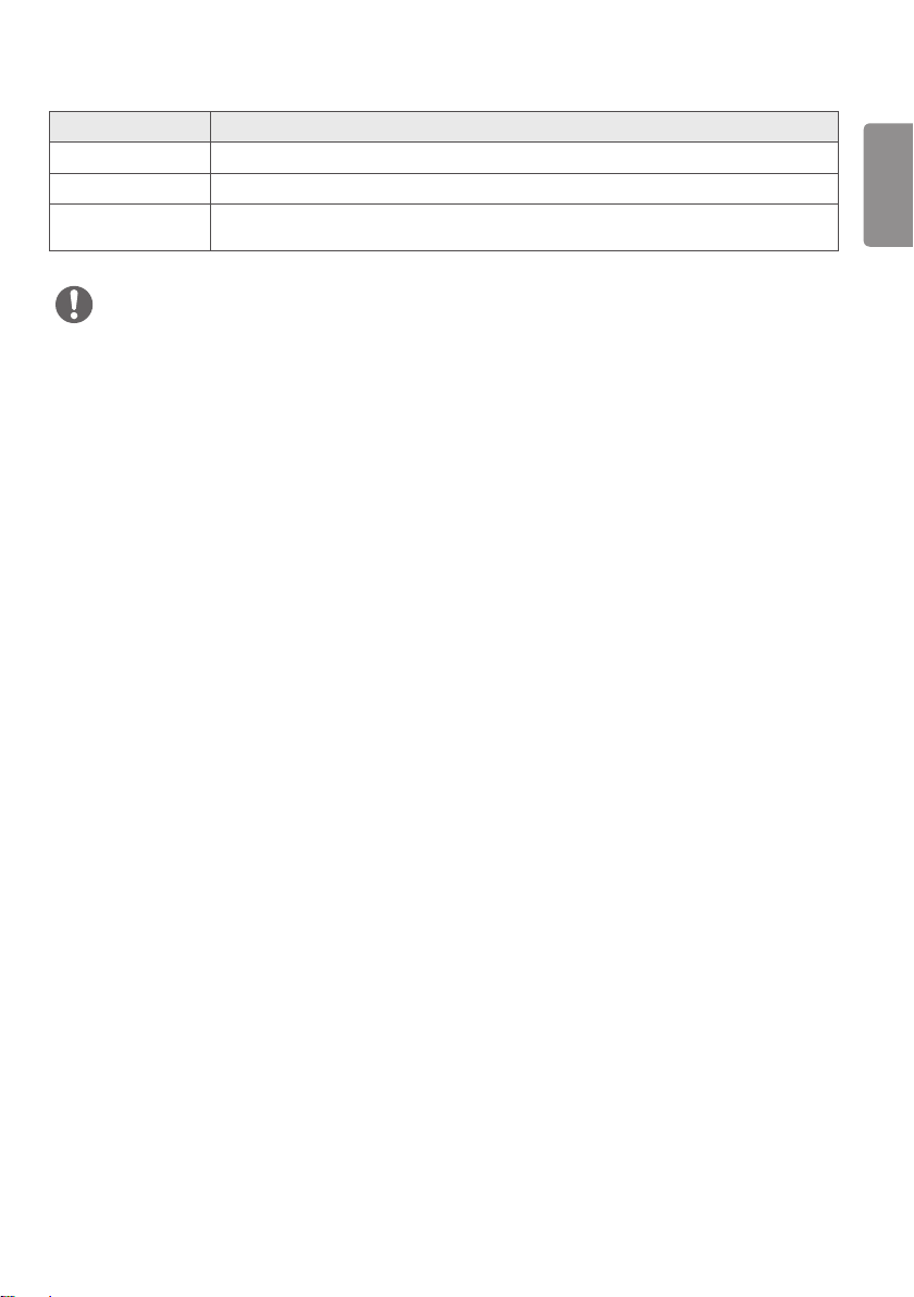
Input Description
PBP / PIP
Displays the screens of two input modes on one monitor.
PIP Size
Adjusts the PIP size. (Small, Medium, Large)
Main/Sub Screen
Change
Toggles between the main screen and the sub screen in PBP / PIP mode.
NOTE
When there is no Sub Screen signal, PIP Size and Main/Sub Screen Change are disabled.
ENGLISH
34
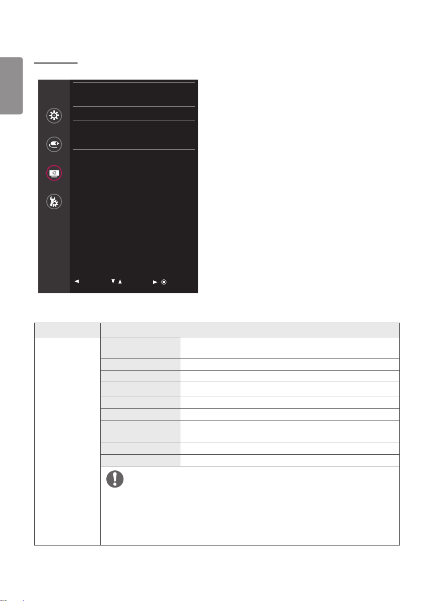
PICTURE
Picture
Quick Settings
Picture Mode Custom >
Picture Adjust >
Input
Color Adjust >
Picture Reset >
Picture
General
: Exit
/ : Move
/ : Ok
The following settings are available.
Picture Description
Picture Mode
Custom Allows the user to adjust each element. The color mode of the main
menu can be adjusted.
Mono Monochrome (black and white) color mode.
sRGB A standard RGB color mode for the monitor and printer.
EBU A standard TV PAL color mode for broadcasts.
REC709 A standard HDTV color mode for broadcasts.
SMPTE-C A standard TV NTSC color mode for broadcasts.
DICOM A mode optimized for viewing medical images.
You can brighten the screen in the OSD menu.
Calibration 1 Adjusts to the last calibrated screen.
Calibration 2 Adjusts to the previously calibrated screen.
NOTE
Brightness Stabilization function can be enabled in Custom mode.
If the Picture Mode is changed in the DisplayPort (DP) input, the screen may flicker or the
resolution of your PC screen may be affected.
Calibration 2: This menu is enabled if you install the TRUE COLOR PRO program and perform
a calibration.
ENGLISH
35
Picture Description
Picture Adjust
Brightness
Adjusts the brightness of the screen.
NOTE
You can turn the Brightness Stabilization to On/ Off by pressing
the button in the Brightness menu.
When the Brightness Stabilization is On, Brightness menus
becomes disabled.
When the Brightness Stabilization is On, SMART ENERGY
SAVING and DFC menus become disabled.
Contrast Adjusts the color contrast of the screen.
Sharpness Adjusts the sharpness of the screen.
Brightness
Stabilization
Maintains the brightness configured for medical environments.
On Adjusts the brightness automatically.
Off Deactivates the function, and allows the user to
configure the brightness.
SUPER RESOLUTION+ High Select this option for crystal clear images. Best for
high-definition video or games.
Middle The optimized picture quality is displayed when a
user wants images between low and high modes for
comfortable viewing. Best for UCC or SD video.
Low The optimized picture quality is displayed when a
user wants smooth and natural images. Best for
still images with less movement.
Off Select this option for the normal user experience.
Disables SUPER RESOLUTION+.
Black Level Sets the offset level. (HDMI only)
Offset: A reference for video signals. Offset is the darkest color that
the monitor can display.
High Keeps the current contrast ratio of the screen.
Low Lowers the black levels and raises the white levels
from the current contrast ratio of the screen.
ENGLISH
36
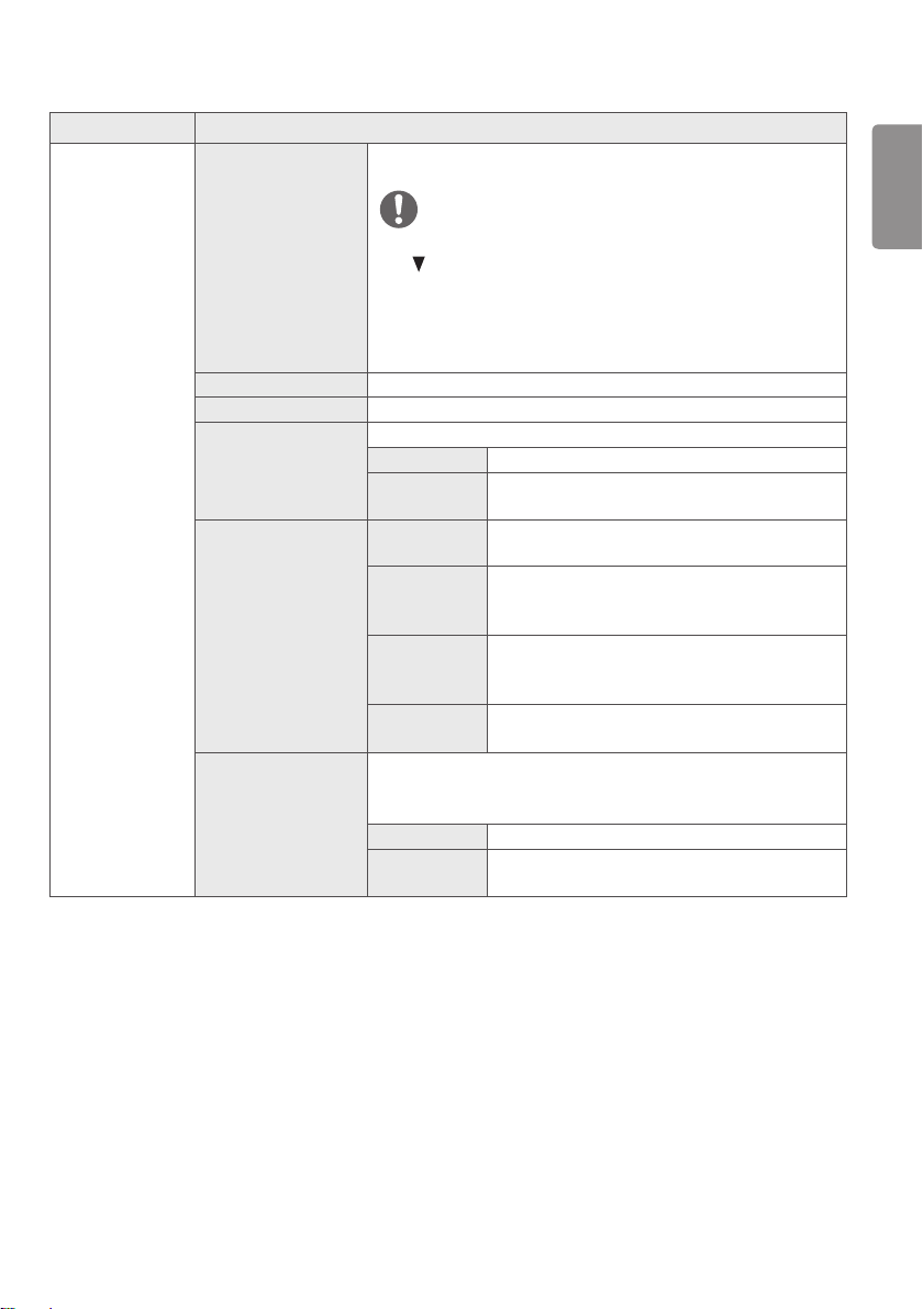
Picture Description
Picture Adjust HDMI ULTRA HD Deep
Color
Provides sharper images when connected to a device supporting
ULTRA HD Deep Color.
NOTE
• If the connected device does not support ULTRA HD Deep Color, the
feature may not work properly.
• If you experience a problem, set HDMI ULTRA HD Deep Color to
Off.
Formats supported at 4K@ 60 Hz
1)
Resolution
Frame rate
(Hz)
Deep color / chroma sampling
8-bit 10-bit
3840 x 2160
59.94
60.00
YCbCr 4:2:0
YCbCr 4:2:2
YCbCr 4:4:4 -
RGB 4:4:4 -
1) Supported when HDMI ULTRA HD Deep Color is set to On.
DFC On Adjusts the brightness automatically according to
the screen.
Off Disables the DFC feature.
Response Time Sets the response time for displayed pictures based on the speed of
the screen.
For a normal environment, Normal is recommended. For a fast-
moving picture, Fast is recommended. Setting the response time to
Fast may cause image sticking.
Fast Sets the response time to fast.
Normal Sets the response time to normal.
Slow Sets the response time to slow.
Off Does not use the response time improvement
feature.
Black Stabilizer Objects can be seen more clearly in dark screen picture by adjusting
the black level.
Increasing the Black Stabilizer value brightens the low gray levels
on the screen. (You can easily distinguish objects on a dark game
screen.)
Reducing the Black Stabilizer value darkens the low gray levels and
increases the dynamic contrast on the screen.
ENGLISH
37
Picture Description
Picture Adjust Uniformity Adjusts the uniformity of screen brightness.
NOTE
• Enabling Uniformity may reduce the overall brightness of the
image.
On Enables the Uniformity feature.
Off Disables the Uniformity feature.
Color Adjust Gamma Custom gamma settings: Gamma 1.8, Gamma 2.0, Gamma 2.2,
Gamma 2.4, Gamma 2.6, DICOM Gamma Curve.
The higher the gamma value, the darker the image becomes. Likewise,
the lower the gamma value, the lighter the image becomes.
Color Temp Adjusts the DICOM Gamma. (Custom, 6500K, 8500K, 9300K,
Manual)
Custom The user can customize the red, green and blue
color.
6500K Sets the picture color to the color temperature of a
reddish 6500K.
8500K Sets the picture color to the color temperatures of
8500K, setting to a color between red and blue.
9300K Sets the picture color to the color temperature of a
bluish 9300K.
Manual Adjusts the color temperature in 500K increments.
(Note that 9300K is supported rather than
9500K.)
Red
You can customize the picture color using red, green and blue.Green
Blue
Six Color Fulfills your color requirements by adjusting the hue and saturation
of the six colors (red, green, blue, cyan, magenta and yellow). The
settings are then saved.
Hue Adjusts the tone of the screen colors.
Saturation Adjusts the saturation of the screen colors. The
lower the value, the less saturated and brighter
the colors become. The higher the value, the more
saturated and darker the colors become.
Picture Reset Returns the colors to the default settings.
ENGLISH
38
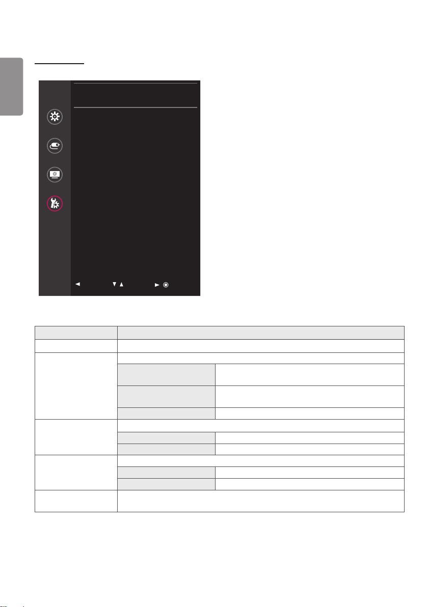
GENERAL
General
Quick Settings
Language English >
SMART ENERGY SAVING Off >
Input
HW Calibration On >
RS-232C >
Picture
LED Control Button 20Sec Time Out >
DVI Power Supply Off >
General
Hot key Settings >
User Preset >
Auto Screen Off On >
DisplayPort 1.2 Enable >
OSD Lock Off >
Reset >
: Exit
/ : Move
/ : Ok
The following settings are available.
General Description
Language Sets the menu screen to the desired language.
SMART ENERGY
SAVING
Conserve energy by using luminance compensation algorithm.
High Saves energy using the high-efficiency SMART ENERGY
SAVING feature.
Low Saves energy using the low-efficiency SMART ENERGY
SAVING feature.
Off Disables the SMART ENERGY SAVING feature.
HW Calibration RS-232C and HW Calibration cannot be used together simultaneously.
On Enables the HW Calibration feature.
Off Disables the HW Calibration feature.
RS-232C RS-232C and HW Calibration cannot be used together simultaneously.
Serial Port Enables or disables the RS-232C feature.
Set ID Configures the Set ID. (Configuration range: 1-10)
LED Control Button Adjusts how long the control button LEDs remain lit. (Always On, 20Sec Time Out, 10Sec
Time Out, 5Sec Time Out)

ENGLISH
39
General Description
DVI Power Supply Supplies power to devices connected to the DVI input port as a dongle without power.
On Activates the DVI Power Supply feature.
Off Deactivates the DVI Power Supply feature.
Hot key Settings Assigns hotkeys for picture settings. Once configured, the assigned menu is activated
when a hotkey is pressed.(PIP Size, Mono, Color Temp, Gamma, Black Stabilizer, Screen
Zoom, Off)
Hotkey 1 Assigns a function to Hotkey 1.
Hotkey 2 Assigns a function to Hotkey 2.
User Preset User Preset allows the user to save or load up to 10 picture quality settings for multiple
connected devices in each preset.
NOTE
You can use User Preset to import or save items in Picture Adjust and Color Adjust of
the Picture menu.
User Name Allows the user to change and register a user name
(Preset 1 ~ Preset 3, User 1 ~ User 7) as the user wants.
The user can enter a user name to be registered by using
the screen keyboard.
Preset 1 ~ Preset 3 are factory-set user names as
samples and the user can change the names.
Load User Settings Allows the user to change the picture quality settings by
loading the User Preset settings.
Save User Settings Saves the current picture quality settings in the
corresponding User Preset.
Preset 1 ~ Preset 3 are factory-set values as samples and
the user can change the values.
Preset 1: Use this preset for bluish color.
Preset 2: Use this preset for greenish color and brighter
low-gradation.
Preset 3: Use this preset to soften the red tone.
User 1 ~ User 7: Initial values are the same as the
factory settings.
Default User Settings Loads the initial basic picture settings.
User Preset Reset Initializes User Preset settings.
Initializes the existing user name and user settings to be
restored to factory settings (Preset 1 ~ Preset 3, User
1 ~ User 7).
ENGLISH
40
General Description
Auto Screen Off The screen turns off automatically when there are no monitor signals for a set period of
time.
On Enables the Auto Screen Off feature.
Off Disables the Auto Screen Off feature.
DisplayPort 1.2
Enables or disables DisplayPort 1.2.
NOTE
Be sure to configure this option according to the DisplayPort version supported by your
graphics card.
Set this option to Off if your graphics card is not compatible.
When DisplayPort 1.2 is disabled, you cannot use the 10-bit output of your graphics
card.
OSD Lock
This feature disables the configuration and adjustment of menus.
On Enables the OSD lock feature.
Off Disables the OSD lock feature.
NOTE
All features other than the Quick Settings menu, the Input List, Aspect Ratio and PBP/
PIP features in the Input menu and the OSD Lock feature in the General menu are
disabled.
Reset Do you want to reset your settings?
Yes Restores the default settings.
No Cancels the reset.
ENGLISH
41
TROUBLESHOOTING
Nothing is displayed on the screen.
Is the monitor's power cord plugged in? Check if the power cord is correctly plugged into the power outlet.
Is the power indicator on? Check your power cable connection and turn the power switch on.
Is the power indicator displaying as green? Check if the input setting is correct when the PC and the product are
connected. (MENU > Quick Settings > Input)
Is the "Out of Range" message
displayed?
This occurs when the signals transferred from your PC (graphics card)
are outside the horizontal or vertical frequency range of your monitor.
Please see the "Product Specification" section of this manual to set the
appropriate frequency.
Is the 'No Signal' message displayed? This is displayed when the signal cable between the PC and the monitor
is missing or disconnected. Check the cable and reconnect it.
The screen may not be displayed
properly when configuring DisplayPort
(DisplayPort) 1.2 in a Mac product.
• DisplayPort 1.2 may not be supported depending on the Mac product.
Please contact the manufacturer.
The screen retains an image.
Does image sticking occur even when the
monitor is turned off?
Displaying a still image for a prolonged period may damage the screen,
resulting in image sticking.
To extend the lifetime of the monitor, use a screensaver.
The screen display is unstable and shaky. Images displayed on the monitor leave shadow trails.
Did you select the appropriate resolution? • If the selected resolution is HDMI 1080i 60/50 Hz (interlaced), the
screen may be flickering. Change the resolution to 1080P or the
recommended resolution.
NOTE
• Vertical Frequency: In order to display an image, the screen must be refreshed dozens of times per second, like a
fluorescent lamp.
The number of times the screen is refreshed per second is called vertical frequency, or refresh rate, and is represented
by Hz.
• Horizontal Frequency: The time it takes to display one horizontal line is called the horizontal cycle.
If 1 is divided by the horizontal interval, the result is the number of horizontal lines displayed per second. This is called
horizontal frequency and is represented by kHz.
ENGLISH
42
NOTE
Check if your graphics card's resolution or frequency is within the range supported by your monitor and set your
graphics card to the recommended (optimal) resolution in Control Panel > Display > Settings in Windows. (The
settings may differ depending on your operating system)
Not setting your graphics card to the recommended (optimal) resolution may result in blurred text, a dimmed screen,
a truncated display area or misalignment of the display.
The setting method may differ depending on the computer and operating system. Some resolutions may not be
available depending on your graphics card's performance. If this is the case, contact the manufacturer of your
computer or graphics card for help.
Some graphics cards may not support the 3840 x 2160 resolution. If the resolution cannot be displayed, contact the
manufacturer of your graphics card.
The display color is abnormal.
Does the display appear discolored (16
colors)?
Set the number of colors to 24-bits (True Color) or above: Control Panel
> Display > Settings > Color Quality in Windows (the settings may
differ depending on your operating system).
Does the display color appear unstable
or monochrome?
Check the connection status of the signal cable and connect it properly
or reinsert your PC's graphics card.
Are there spots on the screen? When using the monitor, pixelated spots (red, green, blue, white or black)
may appear on the screen. This is normal for an LCD screen. It is not an
error, nor is it related to the monitor's performance.
The 'Unknown Monitor' message appears when the monitor is connected.
Did you install the monitor driver? Install the enclosed monitor driver provided with the monitor or go to
the LG Electronics homepage (http://www.lg.com) to download and
install the monitor driver.
Check your graphics card user manual to see if the Plug and Play
function is supported.
ENGLISH
43
PRODUCT SPECIFICATIONS
The product specifications are subject to change without prior notice for product improvements.
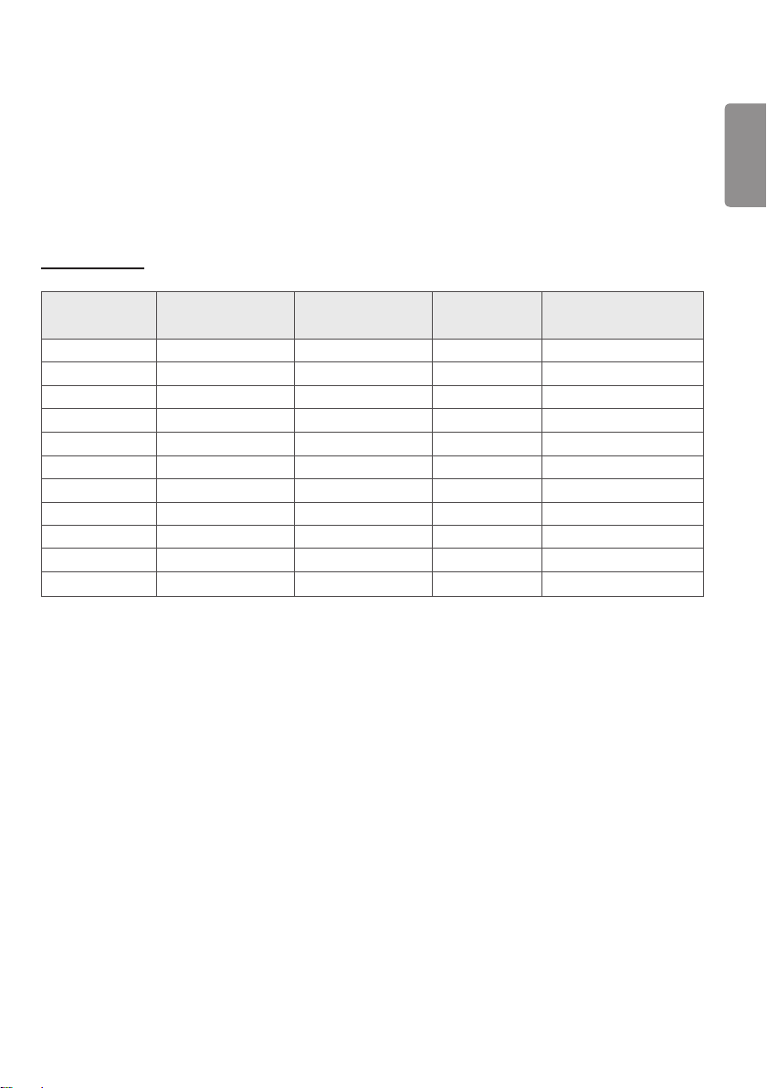
Preset Modes
DisplayPort
Preset Modes
Horizontal Frequency
(kHz)
Vertical Frequency
(Hz)
Polarity (H/V) Remarks
640 x 480 31.469 59.94 -/-
800 x 600 37.879 60.317 +/+
1024 x 768 48.363 60 -/-
1152 x 864 54.347 60.05 +/+
1280 x 720 45 60 +/+
1280 x 1024 63.981 60.02 +/+
1600 x 900 60 60 +/+
1920 x 1080 67.5 60 +/-
2560 x 1440 88.79 59.95 +/-
3840 x 2160 66.66 30 +/-
3840 x 2160 133.32 60 +/-
ENGLISH
44
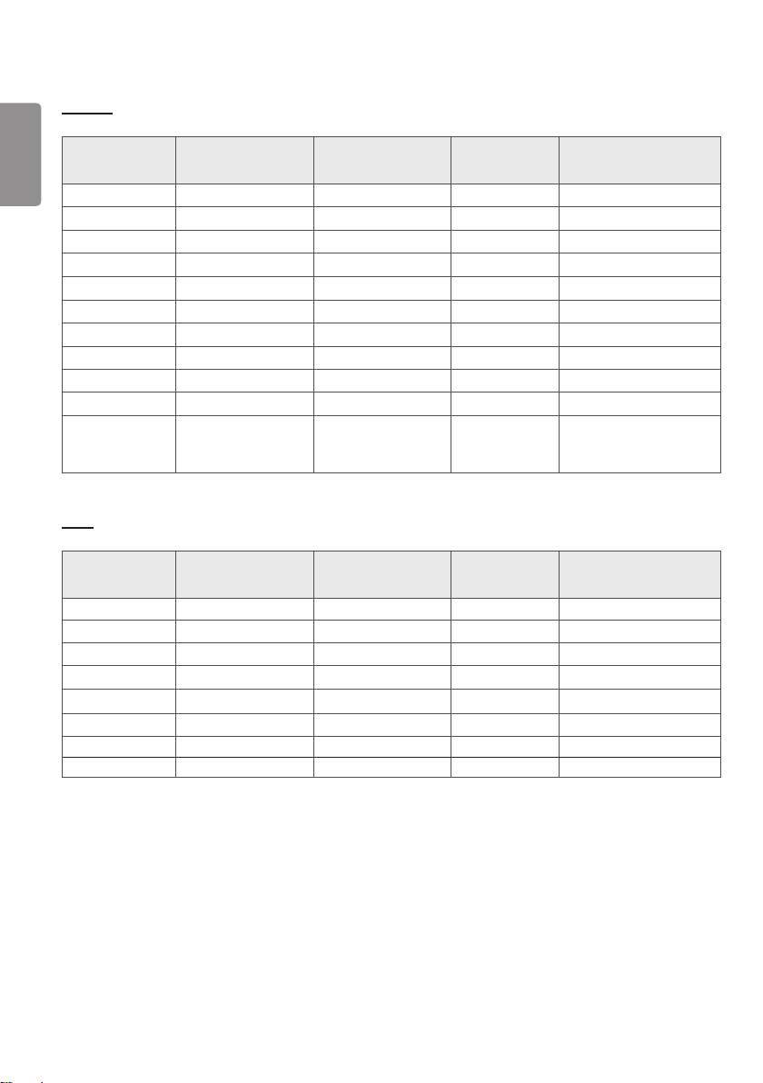
HDMI
Preset Modes
Horizontal Frequency
(kHz)
Vertical Frequency
(Hz)
Polarity (H/V) Remarks
640 x 480 31.469 59.94 -/-
800 x 600 37.879 60.317 +/+
1024 x 768 48.363 60 -/-
1152 x 864 54.347 60.05 +/+
1280 x 720 45 60 +/+
1280 x 1024 63.981 60.02 +/+
1600 x 900 60 60 +/+
1920 x 1080 67.5 60 +/-
2560 x 1440 88.79 59.95 +/-
3840 x 2160 67.5 30 +/-
3840 x 2160 135 60 +/-
When the HDMI ULTRA
HD Deep Color is set
to On
DVI
Preset Modes
Horizontal Frequency
(kHz)
Vertical Frequency
(Hz)
Polarity (H/V) Remarks
640 x 480 31.469 59.94 -/-
800 x 600 37.879 60.317 +/+
1024 x 768 48.363 60 -/-
1152 x 864 54.347 60.05 +/+
1280 x 720 45 60 +/+
1280 x 1024 63.981 60.02 +/+
1600 x 900 60 60 +/+
1920 x 1080 67.5 60 +/-
ENGLISH
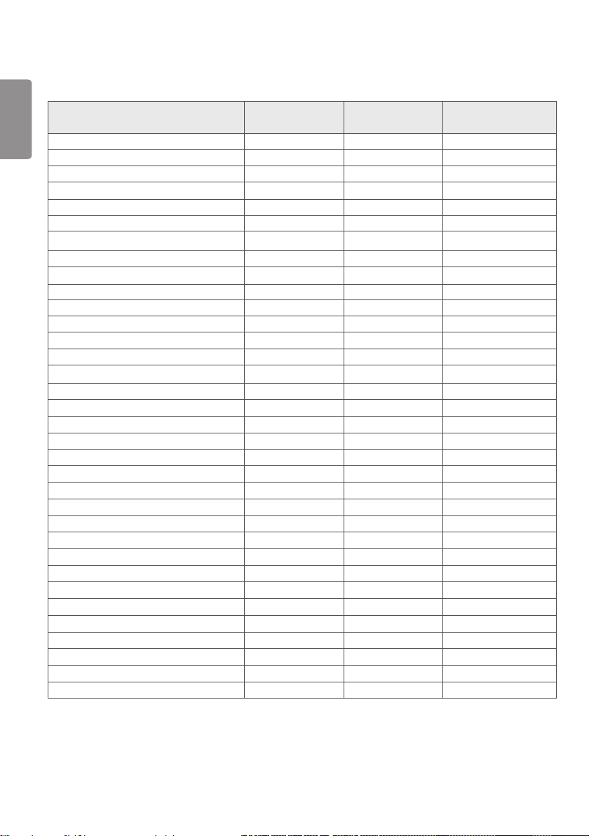
45
Input Timing (Video)
Vertical dimensions Vertical Frequency (Hz) DVI HDMI DP SDI
480i 59.94/60 - - - O
480p 59.94/60 O O O -
576p 50 O O - -
576i 50 - - - O
720p 59.94/60 O O O O
720p 50 O O - O
1080i 59.94/60 O O - O
1080p 59.94/60 O O O O
1080i 50 O O - O
1080p 50 O O - O
1080p 23.98/24 - O - -
1080p 29.97/30 - O - O
2160p 23.98/24 - O - -
2160p 25 - O - -
2160p 29.97/30 - O - -
2160p 50 - O - -
2160p 59.94/60 - O - -
Power indicator
Mode LED Color
On Mode Green
ENGLISH
46
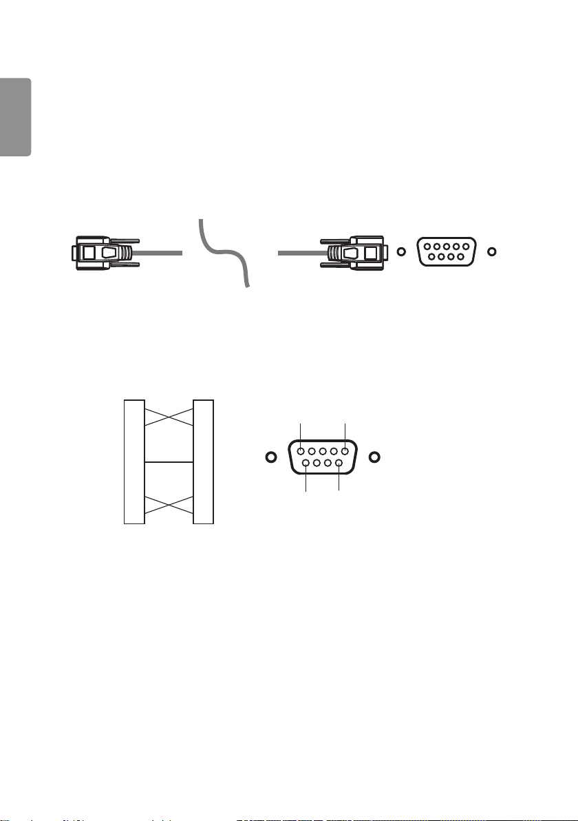
EXTERNAL CONTROLLER SETUP
The actual product may differ from the picture shown.
Connect the RS-232C (serial connector) of the PC to the RS-232C IN connector at the back of the monitor.
Purchase a cable to connect the RS-232C connectors, as the cable is not provided as an accessory.
Use an RS-232C cable to remotely control the monitor (see Figure 1).
RS-232C
(PC) (Monitor)
Figure 1: RS-232C Connection Diagram
PC Monitor
5 1
9
6
2
3
4
5
6
7
8
2
3
4
5
6
7
8
RXD
TXD
DTR
GND
DSR
RTS
CTS
RXD
TXD
DTR
GND
DSR
RTS
CTS
* There are no connections to Pin 1 and Pin 9.

ENGLISH
47
Set ID Function
This function allows you to assign a unique ID to the monitor to control it remotely from your PC.
Please refer to the "Actual Data Structure".
1 Press the [Menu] button.
2 Use the , , , buttons to select General. Then press the OK button.
3 Use the , , , buttons to select Set ID. Then press the OK button.
4 Select a Set ID to assign. Then press the OK button. The Set ID can be a value from 1 to 10.
5 Press the button to exit (pressing the [Menu] button hides the OSD).
Communication Parameters
Baud rate: 9600 bps (UART)
Data length: 8 bits
Parity bit: None
Stop bit: 1 bit
Communication code: ASCII code
Crossed (reverse) cable used.
ENGLISH
48
Command Reference List
Title Command1 Command2
Data
(Hexadecimal)
01. Power k a 00 - 01
02. Screen Mute k d 00 - 01
03. Input select (Main) k b 00 - 03
04. Input select (Sub) k y 00 - 03
05. Aspect Ratio (Main) k c 00 - 02
06. Aspect Ratio (Sub) k o 00 - 01
07. PBP/PIP k n 00 - 05
08. PIP Size k p 00 - 02
09. Main/Sub Screen Change m a 01
10. Picture Mode d x 00 - 08
11. Brightness k h 00 - 64
12. Contrast k g 00 - 64
13. Sharpness k k 00 - 64
14. Brightness Stabilization m b 00 - 01
15. SUPER RESOLUTION+ m c 00 - 03
16. Black Level m d 00 - 01
17. HDMI Ultra HD Deep Color m e 00 - 01
18. DFC m f 00 - 01
19. Response Time m g 00 - 03
20. Black Stabilizer m h 00 - 64
21. Uniformity m i 00 - 01
22. Gamma m j 00 - 05
23. Color Temp k u 00 - 04
24. Red Gain j w 00 - 64
25. Green Gain j y 00 - 64
26. Blue Gain j z 00 - 64
27. Language f i 00 - 10
28. SMART ENERGY SAVING m k 00 - 02
29. LED Control Button m l 00 - 03
30. DVI Power Supply m m 00 - 01
31. Auto Screen Off m n 00 - 01
32. DisplayPort 1.2 m o 00 - 01
33. OSD Lock k m 00 - 01
34. Reset f k 00 - 02

ENGLISH
49
Transmission/Reception Protocol
Transmission
[Command1][Command2][ ][Set ID][ ][Data][Cr]
[Command 1]: j, k, m, x
[Command 2]: This command is used to control the monitor.
[Set ID]: Used to identify the monitor being controlled. [Set ID] can be assigned to each monitor under GENERAL in the
Settings Menu.
A value from 1 to 10 can be assigned. By selecting '0' for the [Set ID] value in the protocol format, you can
control all connected monitors.
* The value is displayed as base 10 on the OSD menu and used as base 16 (0x00 - 0x63) in the
transmission/reception protocol for remote control.
[Data]: Transmits a setting value (Data) required for the command described previously. (base 16)
When the Data ‘FF’ is sent, the setting value corresponding to the specific command is read (Data read mode).
[Cr]: Carriage return, which is ‘0x0D’ in ASCII code.
[ ]: Space, which is ‘0x20’ in ASCII code.
OK Acknowledgment
[Command2][ ][Set ID][ ][OK][Data][x]
When the Data has been successfully received, the monitor sends an ACK response signal in the above format. The
Data showing the current state is received in the Data read mode. The Data from the PC is simply returned in the Data
write mode.

ENGLISH
50
Error Acknowledgment
[Command2][ ][Set ID][ ][NG][Data][x]
When the set receives an abnormal piece of Data for an unsupported function or there is a communication error, it
returns ACK in the format above.
Data 00 : Illegal code
Actual Data Structure (Base 16 Base 10)
See the table below when inserting a base-16 value in [Data].
The channel setup command (ma) uses a 2-byte base-16 value ([Data]) for channel number input.
00: Step 0 32: Step 50 (Set ID 50) FE: Step 254
01: Step 1 (Set ID 1) 33: Step 51 (Set ID 51) FF: Step 255
... ... ...
0A: Step 10 (Set ID 10) 63: Step 99 (Set ID 99) 01 00: Step 256
... ... ...
0F: Step 15 (Set ID 15) C7: Step 199 27 0E: Step 9998
10: Step 16 (Set ID 16) C8: Step 200 27 0F: Step 9999
... ... ...
* Commands may work differently depending on the model and signal.

ENGLISH
51
01. Power (Command: k a)
▶ This controls the monitor power on/off.
Transmission [k][a][ ][Set ID][ ][Data][Cr]
Data 00: Power Off 01: Power On
Ack [a][ ][Set ID][ ][OK/NG][Data][x]
02. Screen Mute (Command: k d)
▶ This controls the monitor display power on/off.
Transmission [k][d][ ][Set ID][ ][Data][Cr]
Data 00: Screen Mute Off 01: Screen Mute On
Ack [d][ ][Set ID][ ][OK/NG][Data][x]
03. Input select (Main) (Command: k b)
▶ This controls the input mode of the main screen.
Transmission [k][b][ ][Set ID][ ][Data][Cr]
Data
00: SDI 01: DVI
02: HDMI 03: DisplayPort
Ack [b][ ][Set ID][ ][OK/NG][Data][x]
04. Input select (Sub) (Command: k y)
▶ This controls the input mode of the sub screen.
Transmission [k][y][ ][Set ID][ ][Data][Cr]
Data
00: SDI 01: DVI
02: HDMI 03: DisplayPort
Ack [y][ ][Set ID][ ][OK/NG][Data][x]

ENGLISH
52
05. Aspect Ratio (Main) (Command: k c)
▶ This adjusts the aspect ratio of the main screen.
Transmission [k][c][ ][Set ID][ ][Data][Cr]
Data
00: Full Wide 01: Original
02: 1:1
Ack [c][ ][Set ID][ ][OK/NG][Data][x]
06. Aspect Ratio (Sub) (Command: k o)
▶ This adjusts the aspect ratio of the sub screen.
Transmission [k][o][ ][Set ID][ ][Data][Cr]
Data 00: Full Wide 01: Original
Ack [o][ ][Set ID][ ][OK/NG][Data][x]
07. PBP/PIP (Command: k n)
▶ This controls the PBP/PIP mode.
Transmission [k][n][ ][Set ID][ ][Data][Cr]
Data
00: Off 01: PBP
02: PIP_LT 03: PIP_RT
04: PIP_LB 05: PIP_RB
Ack [n][ ][Set ID][ ][OK/NG][Data][x]
08. PIP Size (Command: k p)
▶ This adjusts the PIP size.
Transmission [k][p][ ][Set ID][ ][Data][Cr]
Data
00: Small 01: Medium
02: Large
Ack [p][ ][Set ID][ ][OK/NG][Data][x]

ENGLISH
53
09. Main/Sub Screen Change (Command: m a)
▶ This controls the main/sub screen change in PBP mode.
Transmission [m][a][ ][Set ID][ ][Data][Cr]
Data 01: Main/Sub Screen exchange
Ack [a][ ][Set ID][ ][OK/NG][Data][x]
10. Picture Mode (Command: d x)
▶ This controls the picture mode.
Transmission [d][x][ ][Set ID][ ][Data][Cr]
Data
00: Custom 01: Mono
02: sRGB 03: EBU
04: REC709 05: SMPTE-C
06: DICOM 07: Calibration 1
08: Calibration 2
Ack [x][ ][Set ID][ ][OK/NG][Data][x]
11. Brightness (Command: k h)
▶ This adjusts the screen brightness.
Transmission [k][h][ ][Set ID][ ][Data][Cr]
Data Min: 00 - Max: 64
Ack [h][ ][Set ID][ ][OK/NG][Data][x]
12. Contrast (Command: k g)
▶ This adjusts the screen contrast.
Transmission [k][g][ ][Set ID][ ][Data][Cr]
Data Min: 00 - Max: 64
Ack [g][ ][Set ID][ ][OK/NG][Data][x]

ENGLISH
54
13. Sharpness (Command: k k)
▶ Adjusts the sharpness of the screen.
Transmission [k][k][ ][Set ID][ ][Data][Cr]
Data Min: 00 - Max: 64
Ack [k][ ][Set ID][ ][OK/NG][Data][x]
14. Brightness Stabilization (Command: m b)
▶ This adjusts the Brightness Stabilization feature.
Transmission [m][b][ ][Set ID][ ][Data][Cr]
Data 00: Off 01: On
Ack [b][ ][Set ID][ ][OK/NG][Data][x]
15. SUPER RESOLUTION+ (Command: m c)
▶ This controls the SUPER RESOLUTION+ feature.
Transmission [m][c][ ][Set ID][ ][Data][Cr]
Data 00: High 01: Middle
02: Low 03: Off
Ack [c][ ][Set ID][ ][OK/NG][Data][x]
16. Black Level (Command: m d)
▶ This controls the offset level (for HDMI only).
Transmission [m][d][ ][Set ID][ ][Data][Cr]
Data 00: High 01: Low
Ack [d][ ][Set ID][ ][OK/NG][Data][x]
17. HDMI ULTRA HD Deep Color (Command: m e)
▶ This controls the Ultra Deep Color feature. (HDMI only)
Transmission [m][e][ ][Set ID][ ][Data][Cr]
Data 00: On 01: Off
Ack [e][ ][Set ID][ ][OK/NG][Data][x]

ENGLISH
55
18. DFC (Command: m f)
▶ This controls the DFC feature.
Transmission [m][f][ ][Set ID][ ][Data][Cr]
Data 00: On 01: Off
Ack [f][ ][Set ID][ ][OK/NG][Data][x]
19. Response Time (Command: m g)
▶ This controls the response time.
Transmission [m][g][ ][Set ID][ ][Data][Cr]
Data 00: Fast 01: Normal
02: Slow 03: Off
Ack [g][ ][Set ID][ ][OK/NG][Data][x]
20. Black Stabilizer (Command: m h)
▶ This controls the Black Stabilizer feature.
Transmission [m][h][ ][Set ID][ ][Data][Cr]
Data Min: 00 - Max: 64
Ack [h][ ][Set ID][ ][OK/NG][Data][x]
21. Uniformity (Command: m i)
▶ This controls the Uniformity Calibration feature.
Transmission [m][i][ ][Set ID][ ][Data][Cr]
Data 00: On 01: Off
Ack [i][ ][Set ID][ ][OK/NG][Data][x]
22. Gamma (Command: m j)
▶ This adjusts the Gamma settings.
Transmission [m][j][ ][Set ID][ ][Data][Cr]
Data 00: Gamma 1.8 01: Gamma 2.0
02: Gamma 2.2 03: Gamma 2.4
04: Gamma 2.6 05: DICOM Gamma Curve
Ack [j][ ][Set ID][ ][OK/NG][Data][x]

ENGLISH
56
23. Color Temp (Command: k u)
▶ This adjusts the screen color temperature.
Transmission [k][u][ ][Set ID][ ][Data][Cr]
Data
00: Custom 01: 6500K
02: 8500K 03: 9300K
04: Manual
Ack [u][ ][Set ID][ ][OK/NG][Data][x]
24. Red Gain (Command: j w)
▶ This adjusts the red gain.
Transmission [j][w][ ][Set ID][ ][Data][Cr]
Data Min: 00 - Max: 64
Ack [w][ ][Set ID][ ][OK/NG][Data][x]
25. Green Gain (Command: j y)
▶ This adjusts the green gain.
Transmission [j][y][ ][Set ID][ ][Data][Cr]
Data Min: 00 - Max: 64
Ack [y][ ][Set ID][ ][OK/NG][Data][x]
26. Blue Gain (Command: j z)
▶ This adjusts the blue gain.
Transmission [j][z][ ][Set ID][ ][Data][Cr]
Data Min: 00 - Max: 64
Ack [z][ ][Set ID][ ][OK/NG][Data][x]
27. Language (Command: f i)
▶ This adjusts the language of the OSD.
Transmission [f][i][ ][Set ID][ ][Data][Cr]
English - Korean (17 languages)
Ack [i][ ][Set ID][ ][OK/NG][Data][x]

ENGLISH
57
28. SMART ENERGY SAVING (Command: m k)
▶ This adjusts the SMART ENERGY SAVING feature.
Transmission [m][k][ ][Set ID][ ][Data][Cr]
Data 00: High 01: Low
02: Off
Ack [k][ ][Set ID][ ][OK/NG][Data][x]
29. LED Control Button (Command: m l)
▶ Adjusts how long the control button LEDs remain lit.
Transmission [m][l][ ][Set ID][ ][Data][Cr]
Data 00: Always On 01: 20sec time out
02: 10sec time out 03: 5sec time out
Ack [l][ ][Set ID][ ][OK/NG][Data][x]
30. DVI Power Supply (Command: m m)
▶ This controls the DVI Power Supply feature.
Transmission [m][m][ ][Set ID][ ][Data][Cr]
Data 00: On 01: Off
Ack [m][ ][Set ID][ ][OK/NG][Data][x]
31. Auto Screen Off (Command: m n)
▶ This adjusts the time after which the screen turns off automatically when there are no monitor signals.
Transmission [m][n][ ][Set ID][ ][Data][Cr]
Data 00: On 01: Off
Ack [n][ ][Set ID][ ][OK/NG][Data][x]
32. DisplayPort 1.2 (Command: m o)
▶ This enables or disables DisplayPort 1.2.
Transmission [m][o][ ][Set ID][ ][Data][Cr]
Data 00: Enable 01: Disable
Ack [o][ ][Set ID][ ][OK/NG][Data][x]

ENGLISH
58
33. OSD Lock (Command: k m)
▶ This controls the OSD Lock feature.
Transmission [k][m][ ][Set ID][ ][Data][Cr]
Data 00: Off 01: On
Ack [m][ ][Set ID][ ][OK/NG][Data][x]
34. Reset (Command: f k)
▶ This controls the reset operation.
Transmission [f][k][ ][Set ID][ ][Data][Cr]
Data 00: Picture Reset 01: Factory Reset
02: User Preset Reset
Ack [k][ ][Set ID][ ][OK/NG][Data][x]

WARNING: This equipment is compliant with Class A of
CISPR 32. In a residential environment this equipment may
cause radio interference.
Read the Owner's Manual (CD) carefully and keep it at
hand. Please note that the label attached to the product
provides information for product support.
Model
Serial No.
To obtain the source code under GPL, LGPL, MPL, and other
open source licenses, that is contained in this product, please
visit http://opensource.lge.com.
In addition to the source code, all referred license terms,
warranty disclaimers and copyright notices are available for
download.
LG Electronics will also provide open source code to you
on CD-ROM for a charge covering the cost of performing
such distribution (such as the cost of media, shipping, and
handling) upon email request to opensour[email protected]om. This
offer is valid for three (3) years from the date on which you
purchased the product.

