Loading ...
Loading ...
Loading ...
Installation
92
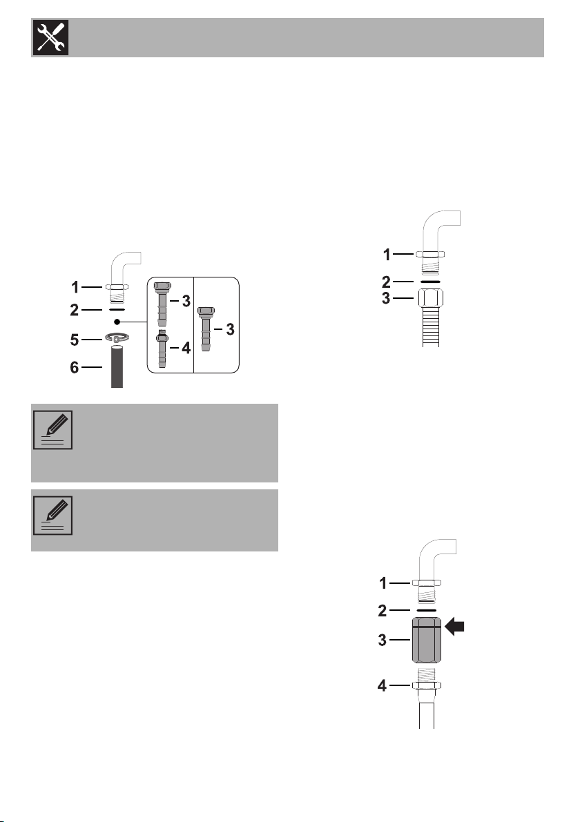
Carefully screw the hose connector 3 to the
appliance’s gas connector 1 (½” thread
ISO 228-1), placing the seal 2 between
them. The hose connector 4 can also be
screwed to the hose connector 3,
depending on the diameter of the gas hose
used. After having tightened the hose
connector(s), push the gas hose 6 onto the
hose connector and secure it with the clamp
5 that is compliant with the standard in
force.
Connection with a steel hose
Make the connection to the gas mains
using a continuous wall steel hose whose
specifications comply with the applicable
standard.
Carefully screw the connector 3 to the gas
connector 1 of the appliance, placing the
seal 2 between them.
Connection with a steel hose with
bayonet fitting
Carry out the connection to the gas mains
using a steel hose with bayonet fitting
compliant with B.S. 669. Apply insulating
material to the thread of the gas hose
connector 4 and then tighten the adapter 3.
Screw the assembly to the movable
connector 1 of the appliance, placing the
supplied seal 2 between them.
Connection using a rubber hose
complying with current standards is
only permitted if the hose can be
inspected along its entire length.
The inside diameter of the hose
must be 8 mm for LPG and 13 mm
for Natural gas and Town gas.
Loading ...
Loading ...
Loading ...