Installation
Instructions
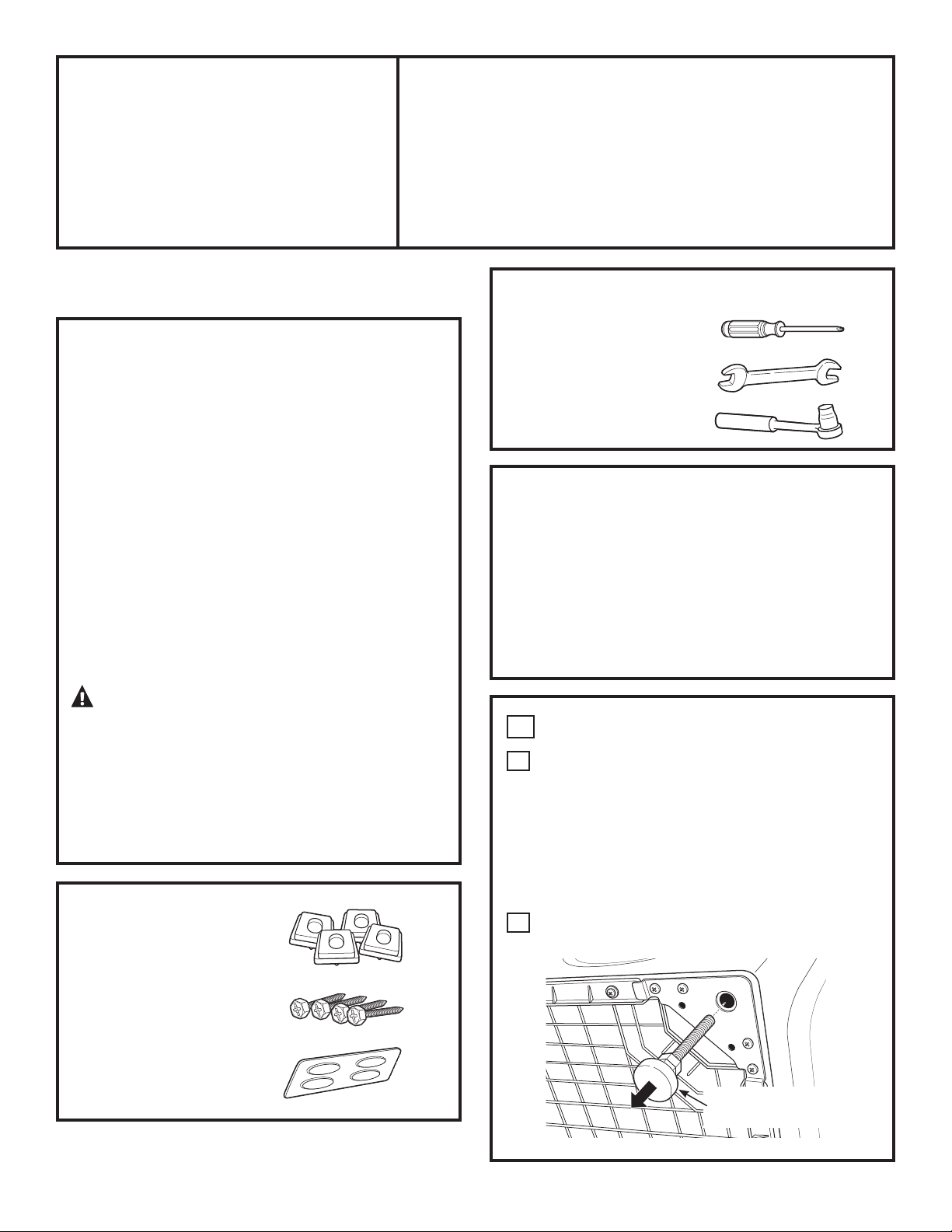
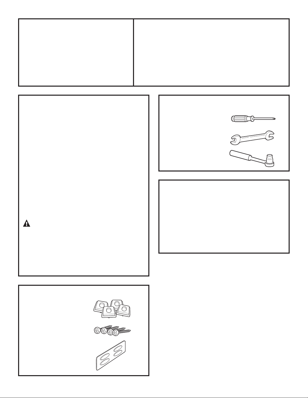
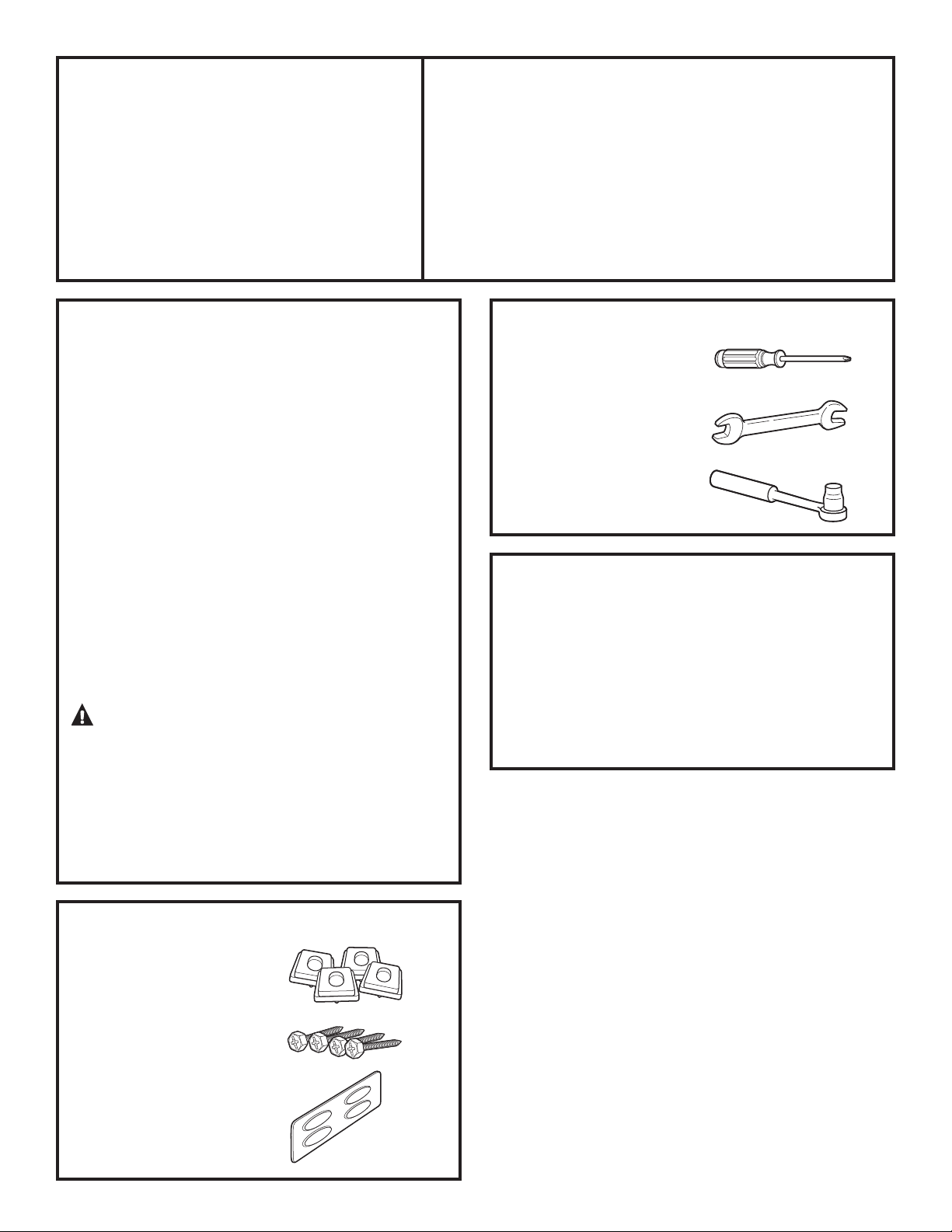
KIT CONTENTS
4 Support Pads
4 Mounting Screws
Drawer Divider
1
SBSD137, SBSD227
TOOLS YOU WILL NEED
Phillips Head
Screwdriver
9/16” Open End Wrench
or Adjustable Wrench
8 mm Socket Wrench
1
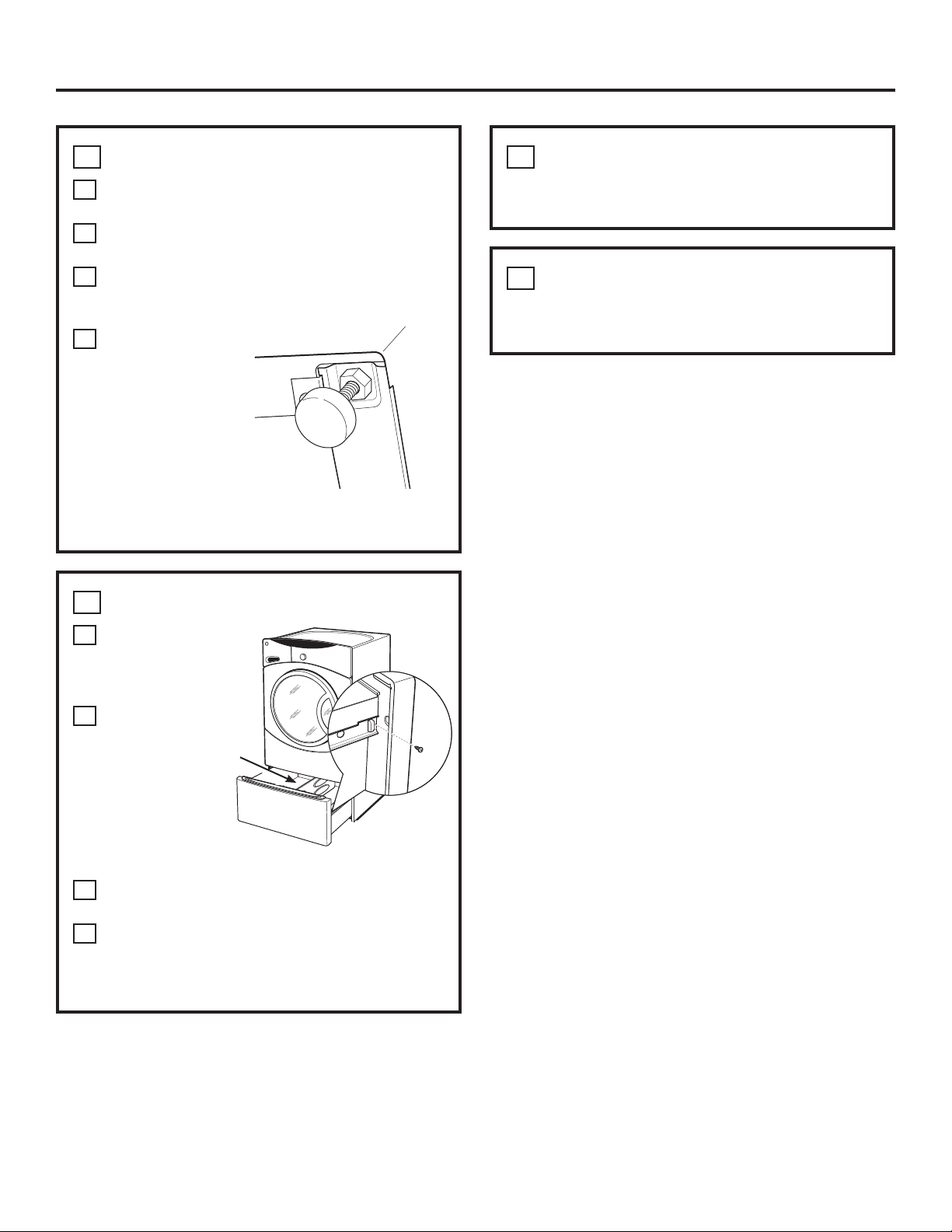
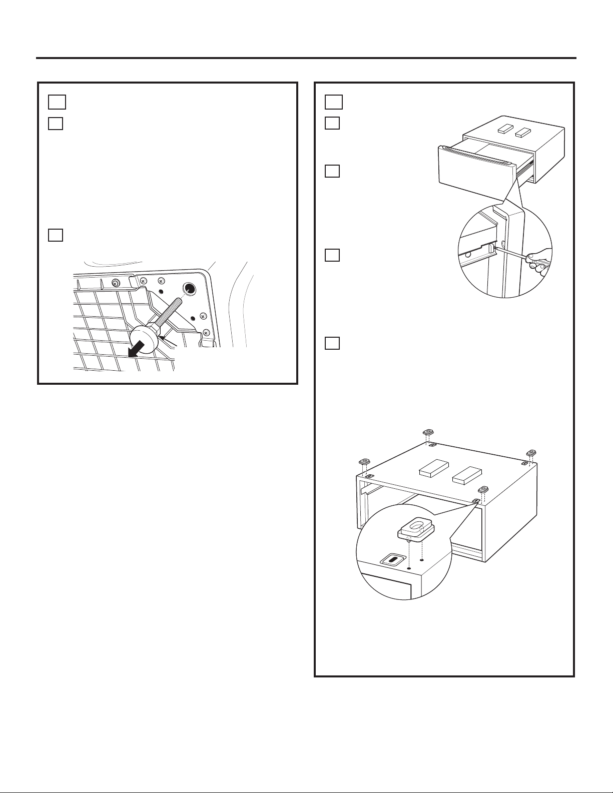
REMOVE THE LEVELING LEGS
A
Carefully lay the washer or dryer on its side to
access the leveling legs on the bottom of the
appliance.
IMPORTANT: Do not lay the washer or dryer on
its back! Do not remove the shipping bolts on the
back side of the washer. The bolts must remain in
place until the washer is returned to an upright
position.
B
Use an open-end wrench to remove the
washer or dryer leveling legs.
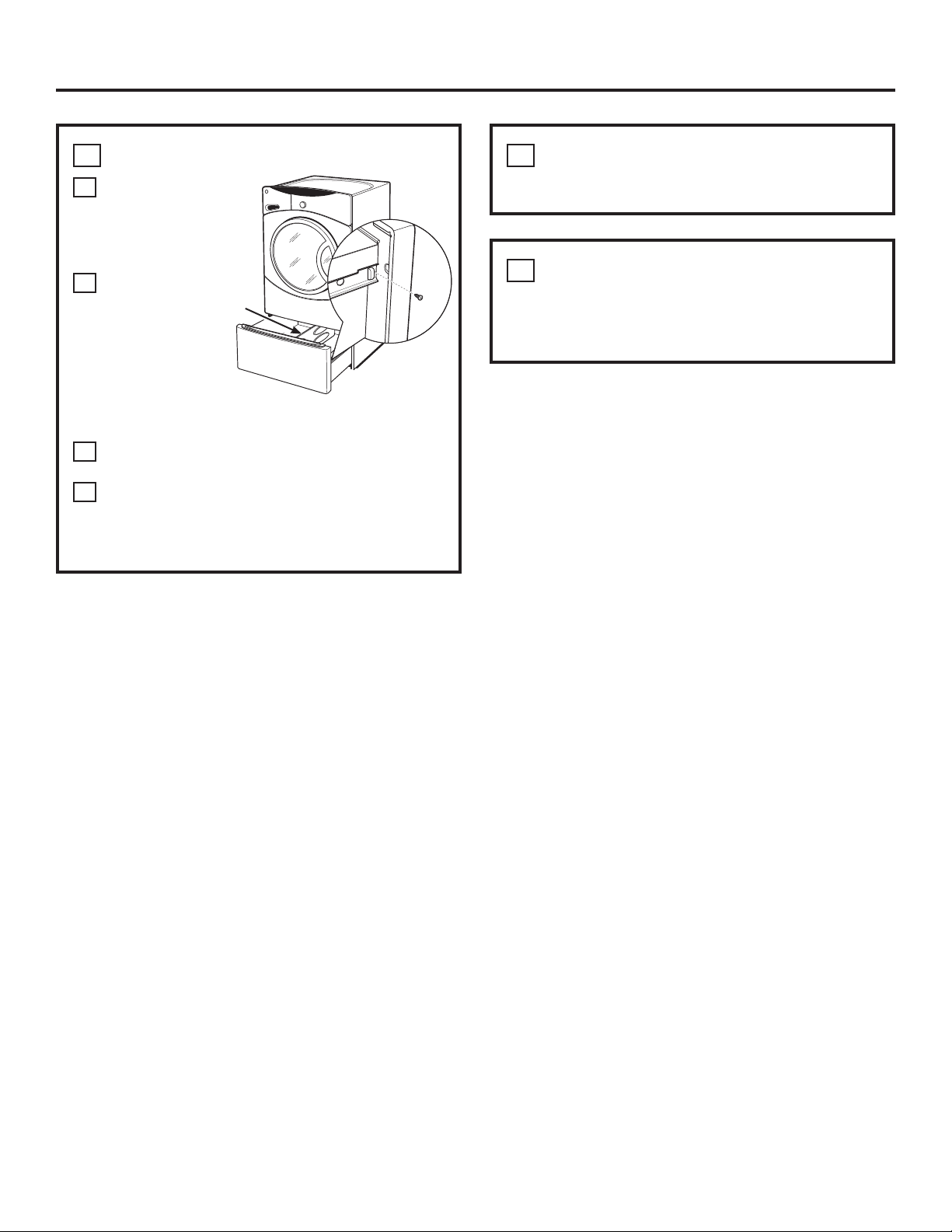
INSTALLATION PREPARATION
Remove the packaging.
The Drawer divider is taped at the top of the
shipping carton. Remove the divider and set aside
for final installation.
Flatten the product carton to use as a pad
to lay the washer or dryer down on its side.
Continue using the carton to protect the finished floor
in front of the installation location.
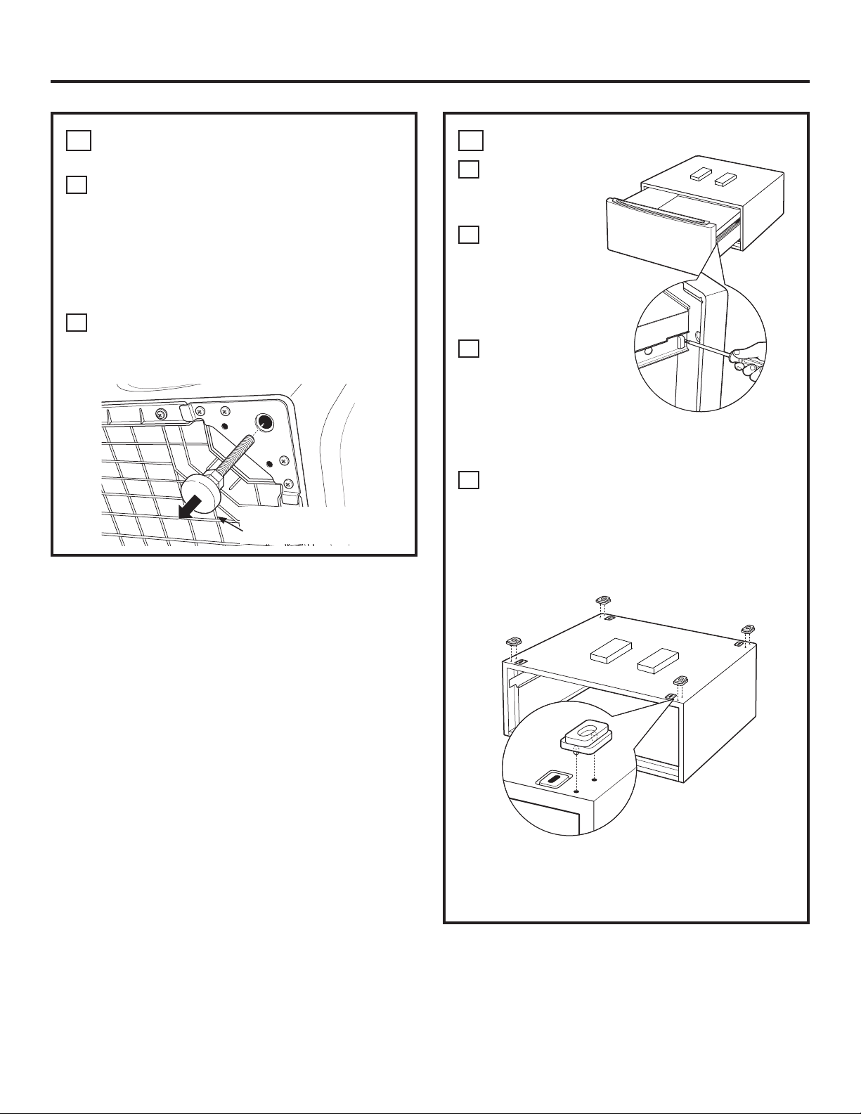
Back out and remove
all 4 leveling legs
Instructions en français : ................ 4
Instrucciones en español: ............... 8
For Washer Models: GBVH5140, GBVH6260, GCVH6260, GCVH6600, GCVH6800, GFAN1000,
GFAN1100,
GFWH1200, GFWH1300, GFWH1400, GFWH1405, GFWH2400,
GFWH2405, GFWN1000, GFWN1100, GFWN1200, GFWN1300, GFWS1500,
GFWS1505, GFWS3500, GFWS3505,
GHDVH626, GHDVH670,
GMAN1200,
WBVH5100,
WBVH6240,
WCVH5300,
WCVH6260, WCVH6600,
WCVH6800,
WHDVH626 & WHDVH660
For Dryer Models: DBVH510, DBVH512, DCVH515, DCVH660, DHDVH52, DHDVH66,
GFDM245, GFDN100, GFDN110, GFDN120, GFDN130, GFDN240, GFDN245,
GFDS140, GFDS145, GFDS150, GFDS155, GFDS350, GFDS355, GFMN100,
GFMN110, GFMN240, GFMS350, GFMS355, GMMN120,
PBVH415, PCVH565,
PCVH680,
PDVH515, PHDVH52 & PHDVH57
BEFORE YOU BEGIN
Read these instructions completely
and carefully.
•
IMPORTANT ³6DYHWKHVHLQVWUXFWLRQV
for local inspector’s use.
•
IMPORTANT ³2EVHUYHDOOJRYHUQLQJ
codes and ordinances.
• Note to Consumer – Keep these instructions with
your Owner’s Manual
for future reference.
• Completion time –
1 to 2 hours
• Proper installation is the responsibility
of the installer.
• Product failure due to improper installation is not
covered under the Warranty.
CAUTION ³'XHWRWKHVL]HDQGZHLJKW
of these products, and to reduce the risk of
personal injury or damage to the product,
TWO PEOPLE ARE REQUIRED
FOR PROPER INSTALLATION.
• See washer and dryer installation instructions
for additional installation requirements and
guidelines.
49-90321-2 175D1807P589 11-13 GE
2
Installation Instructions
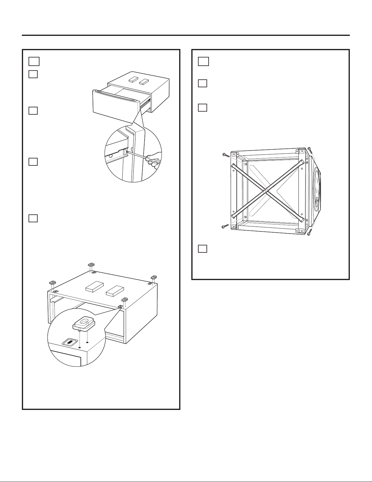
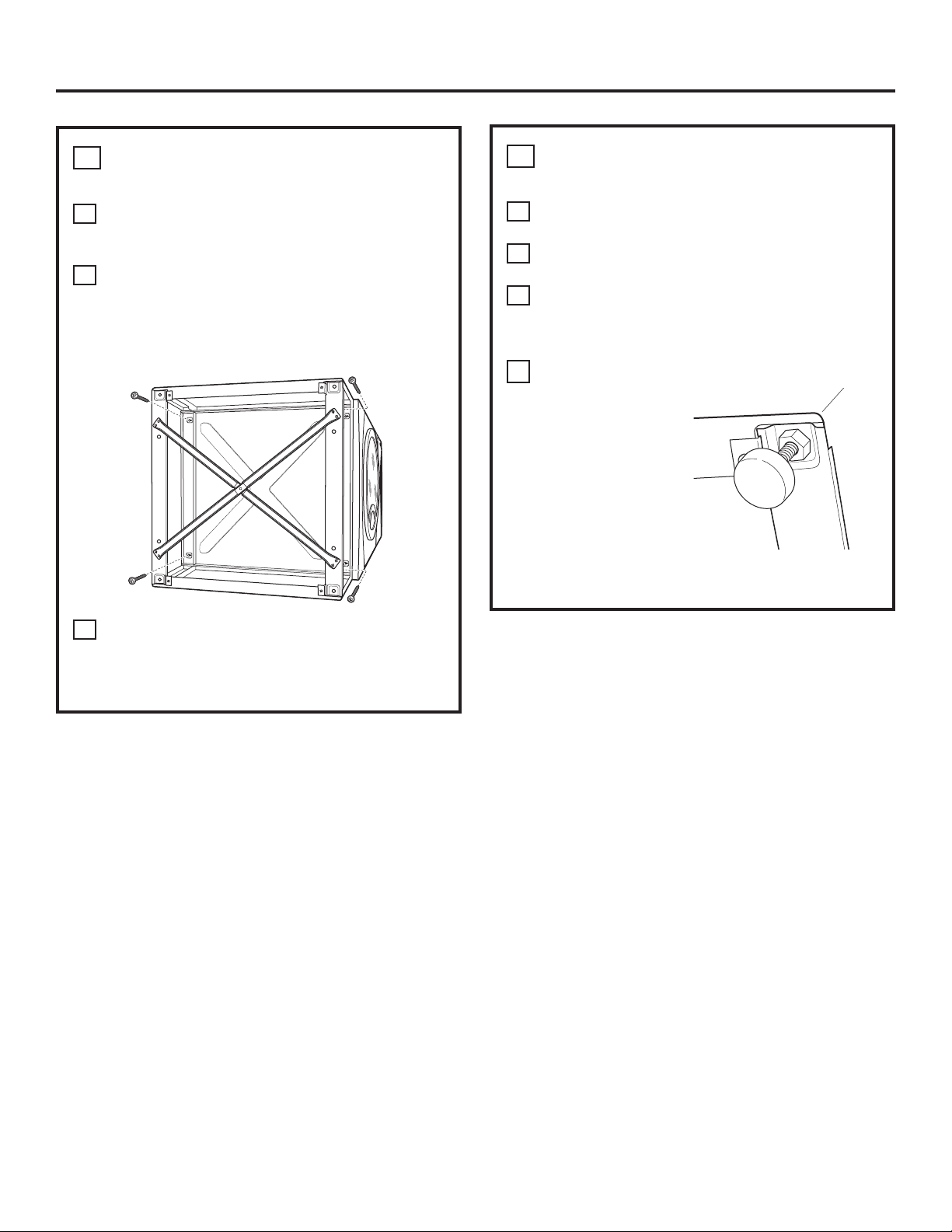
3
INSTALL THE PEDESTAL
TO THE WASHER OR DRYER
A
Place the pedestal against the bottom
of the unit. Check to be sure the drawer front
is at the front of the unit.
B
Align the holes in the pedestal with
the holes in the bottom of the unit.
Use a Phillips screwdriver to install
the 4 screws through the pedestal
DQGLQWRWKHXQLW³GRQRWWLJKWHQ
C
Slide the pedestal toward the unit,
until it is aligned front to back. Use an
8 mm socket wrench to securely tighten the
screws.
2
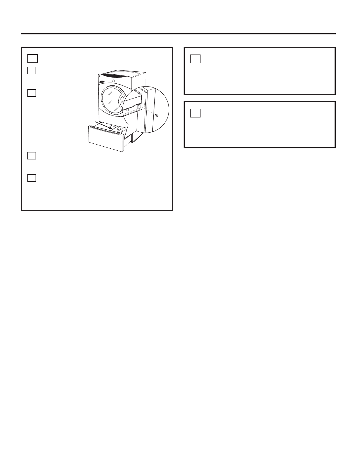
PREPARE THE PEDESTAL
A
Pull the
drawer out
as far as it
will go.
B
Remove screws
from drawer
slides. Slide
drawer out of
the base and set
aside.
C
Do not remove
the foam blocks
on the top of the
pedestal.
FOR DRYERS ONLY:
D
Locate the 4 support pads from the parts
package. Each pad has 2 protrusions that fit
into the holes on top of the pedestal. Press the
rubber pads into each set of corner holes on
the top of the pedestal as shown.
NOTE: The support pads should be installed on
the dryer only. DO NOT INSTALL THESE PADS ON
THE WASHER PEDESTAL.
3
Installation Instructions
4
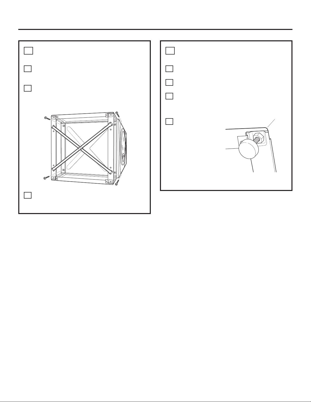
LEVEL THE WASHER OR DRYER
A
Locate the 4 legs from the parts package and
install.
B
Stand the washer or dryer upright. Move it
close to its final location.
C
Make sure that the washer or dryer
is level by placing a spirit level on top. Check
side to side and front to back.
D
Use an open
ended wrench to
adjust the legs in
and out. Tighten
the lock nut
against the
bottom of
the pedestal.
127(7RPLQLPL]HYLEUDWLRQWKHORFNLQJQXWV
must be tight.
6
REMOVE SHIPPING SCREWS
Remove the 4 shipping screws on the back side of the
unit.
5
REINSTALL THE DRAWER
A
Check to
be sure the
slides are
closed.
B
Slide the
drawer
into the
opening.
Align the
drawer
supports to
the slides on
each side.
C
Reinstall the original screws into each drawer
slide. Tighten both screws.
D
Open the drawer fully. Slide drawer divider
into slots in the center of the drawer. The
drawer should slide smoothly when you push
it closed.
7
FINALIZE THE INSTALLATION
Refer to the washer or dryer Installation Instructions
to complete the installation.
SPECIFICATIONS SUBJECT TO CHANGE WITHOUT NOTICE
Drawer
divider
Instructions
d’installation
CONTENU DE LA TROUSSE
4 coussinets de support
4 vis de montage
Séparateur de tiroir
4
AVANT DE COMMENCER
Lisez attentivement et en entier toutes ces
instructions.
•
IMPORTANT ³&RQVHUYH]FHV
instructions à utiliser par l’inspecteur local.
•
IMPORTANT ³2EVHUYH]WRXVOHVFRGHV
et ordonnances en cours.
• Note au consommateur²&RQVHUYH]FHV
instructions avec votre manuel du propriétaire à
titre de référence.
• Délai d’exécution –
1 à 2 heures
8QHERQQHLQVWDOODWLRQHVWODUHVSRQVDELOLWpGH
l’installateur.
• Toute défaillance du produit suite à une
mauvaise installation n’est pas couverte sous la
garantie.
MISE EN GARDE ³jFDXVHGHOD
taille et du poids de ces produits, et pour réduire
le risque de blessures personnelles ou de
dommages au produit, IL FAUT DEUX PERSONNES
POUR UNE BONNE INSTALLATION.
5HSRUWH]YRXVDX[LQVWUXFWLRQVG·LQVWDOODWLRQGH
la laveuse et de la sécheuse pour les directives et
H[LJHQFHVVXSSOpPHQWDLUHVG·LQVWDOODWLRQ
SBSD137, SBSD227
OUTILS DONT VOUS AUREZ BESOIN
Tournevis Phillips
&OpRXYHUWHGHSR
RXFOpUpJODEOH
&OpjGRXLOOHGHPP
PRÉPARATION DE L’INSTALLATION
5HWLUH]O·HPEDOODJH
Le séparateur de tiroir est collé dans le haut du
FDUWRQG·H[SpGLWLRQ5HWLUH]OHVpSDUDWHXUHWPHWWH]OH
de côté pour l’installation finale.
Défaites le carton du produit pour l’utiliser comme
coussin où déposer la laveuse ou la sécheuse sur le
F{Wp&RQWLQXH]jXWLOLVHUOHFDUWRQSRXUSURWpJHUOH
plancher fini devant le site d’installation.
Pour les modèles laveuses : GBVH5140, GBVH6260, GCVH6260, GCVH6600, GCVH6800,
GFAN1000, GFAN1100,
GFWH1200, GFWH1300, GFWH1400, GFWH1405,
GFWH2400, GFWH2405, GFWN1000, GFWN1100, GFWN1200, GFWN1300,
GFWS1500, GFWS1505, GFWS3500, GFWS3505,
GHDVH626, GHDVH670,
GMAN1200,
WBVH5100, WBVH6240,
WCVH5300,
WCVH6260, WCVH6600,
WCVH6800,
WHDVH626 et WHDVH660
Pour les modèles sécheuses : DBVH510, DBVH512, DCVH515, DCVH660, DHDVH52,
DHDVH66,
GFDM245, GFDN100, GFDN110, GFDN120, GFDN130, GFDN240,
GFDN245, GFDS140, GFDS145, GFDS150, GFDS155, GFDS350, GFDS355,
GFMN100, GFMN110, GFMN240, GFMS350, GFMS355, GMMN120,
PBVH415,
PCVH565,
PCVH680,
PDVH515, PHDVH52 et PHDVH57
2
PRÉPAREZ LE SOCLE
A
7LUH]OHWLURLU
aussi loin que
SRVVLEOH
B
5HWLUH]OHVYLVGHV
glissières de
WLURLU*OLVVH]HW
VRUWH]OHWLURLUGH
ODEDVHHWPHWWH]
de côté.
C
1HUHWLUH]SDVOHV
EORFVGHPRXVVH
situés sur le
dessus du
piédestal.
POUR LES SÉCHEUSES SEULEMENT :
D
7URXYH]OHVFRXVVLQHWVGHVXSSRUWGDQVOH
SDTXHWGHSLqFHV&KDTXHFRXVVLQHWD
SURWXEpUDQFHVTXLV·DMXVWHQWGDQVOHVWURXVVXU
OHGHVVXVGXVRFOH3UHVVH]WRXVOHVFRXVVLQHWV
GHFDRXWFKRXFGDQVFKDTXHHQVHPEOHGHWURXV
dans les coins sur le dessus du socle tel
qu’indiqué.
REMARQUE : les coussinets de support doivent être
installés seulement sur la sécheuse. N’INSTALLEZ
PAS CES COUSSINETS SUR LE SOCLE DE LA LAVEUSE.
5
Instructions d’installation
1
RETIREZ LES PIEDS
DE NIVELLEMENT
A
'pSRVH]DYHFVRLQODODYHXVHRXODVpFKHXVHVXU
le côté pour accéder
DX[SLHGVGHQLYHOOHPHQWDXEDVGHO·DSSDUHLO
IMPORTANT: ne déposez pas la laveuse ou la
sécheuse sur le dos ! Ne retirez pas les boulons
G·H[SpGLWLRQjO·DUULqUHGHODODYHXVH/HVERXORQV
GRLYHQWUHVWHUHQSODFHMXVTX·jFHTXHODODYHXVH
revienne en position verticale.
B
8WLOLVH]XQHFOpRXYHUWHSRXUUHWLUHUOHVSLHGVGH
nivellement de la laveuse ou
de la sécheuse.
6RUWH]HWUHWLUH]OHV
pieds de nivellement
4
METTEZ LA LAVEUSE ET
LA SÉCHEUSE À NIVEAU
A
7URXYH]OHVSLHGVGDQVOHSDTXHWGHSLqFHVHW
LQVWDOOH]
B
5HOHYH]ODODYHXVHRXODVpFKHXVH5DSSURFKH]
l’appareil de sa position finale.
C
$VVXUH]YRXVTXHODODYHXVHRXTXHODVpFKHXVH
VRLWjQLYHDXHQSODoDQWXQQLYHDXjEXOOHG·DLU
VXUOHGHVVXV9pULILH]G·XQF{WpjO·DXWUHHW
d’avant vers l’arrière.
D
8WLOLVH]XQHFOp
ouverte pour
DMXVWHUOHVSLHGV
vers l’intérieur et
YHUVO·H[WpULHXU
5HVVHUUH]OH
FRQWUHpFURX
FRQWUHOHEDV
du socle.
REMARQUE : pour réduire la vibration, les
contre-écrous doivent être serrés.
Instructions d’installation
6
3
INSTALLEZ LE SOCLE À LA LAVEUSE
OU LA SÉCHEUSE
A
3ODFH]OHVRFOHFRQWUHOHEDVGHO·DSSDUHLO
9pULILH]SRXUYRXVDVVXUHUTXHOHGHYDQWGXWLURLU
est à l’avant de l’appareil.
B
$OLJQH]OHVWURXVGXVRFOHDYHFOHVWURXV
DXEDVGHO·DSSDUHLO8WLOLVH]XQWRXUQHYLV3KLOOLSV
pour installer les 4 vis à travers
OHVRFOHHWGDQVO·DSSDUHLO³QHUHVVHUUH]SDVWURS
C
*OLVVH]OHVRFOHYHUVO·DSSDUHLOMXVTX·jFHTX·LO
V·DOLJQHG·DYDQWjO·DUULqUH8WLOLVH]XQHFOpj
GRXLOOHGHPPSRXUELHQUHVVHUUHUOHVYLV
5
RÉINSTALLEZ LE TIROIR
A
9pULILH]SRXU
vous assurer
que les
glissières sont
fermées.
B
*OLVVH]
le tiroir
dans
l’ouverture.
$OLJQH]OHV
supports du
tiroir avec les
glissières de
chaque côté.
C
5pLQVWDOOH]OHVYLVRULJLQDOHVGDQVFKDTXH
JOLVVLqUHGHWLURLU5HVVHUUH]OHVGHX[YLV
D
2XYUH]HQWLqUHPHQWOHWLURLU*OLVVH]OH
séparateur de tiroir dans les fentes au centre du
tiroir. Le tiroir devrait alors glisser en douceur
ORUVTXHYRXVOHSRXVVH]SRXUOHIHUPHU
7
Instructions d’installation
6
RETIREZ LES VIS D’EXPÉDITION
5HWLUH]OHVYLVG·H[SpGLWLRQjO·DUULqUHGHO·DSSDUHLO
7
FINALISEZ L’INSTALLATION
5HSRUWH]YRXVDX[LQVWUXFWLRQVG·LQVWDOODWLRQ
de la laveuse ou de la sécheuse pour terminer
l’installation.
SPÉCIFICATIONS SUJETTES À CHANGEMENT SANS PRÉAVIS
Séparateur
de tiroir
Instrucciones
para la
instalación
CONTENIDO DEL KIT
4 planchuelas de soporte
4 tornillos de montaje
Divisor de cajón
8
ANTES DE COMENZAR
Lea atenta y completamente todas las
instrucciones.
•
IMPORTANTE ³JXDUGHHVWDV
instrucciones para que el inspector local pueda
usarlas.
•
IMPORTANTE ³FXPSODFRQWRGRVORV
FyGLJRV\RUGHQDQ]DVFRUUHVSRQGLHQWHV
• Nota para el consumidor ²JXDUGHHVWDV
instrucciones con el Manual del usuario para
consultarlas en el futuro.
• Tiempo de instalación –
1 a 2 horas
• La correcta instalación es responsabilidad del
instalador.
• La falla del producto debido a una instalación
incorrecta no está cubierta
por la Garantía.
PRECAUCIÓN ³GHELGRDOWDPDxR\
peso de estos productos y para reducir el riesgo
GHOHVLRQHVSHUVRQDOHVRGDxRVDOSURGXFWR6(
REQUIEREN DOS PERSONAS PARA SU CORRECTA
INSTALACIÓN.
• Consulte las instrucciones de instalación
GHODODYDGRUD\ODVHFDGRUDSDUDYHUORV
UHTXLVLWRV\SDXWDVGHLQVWDODFLyQDGLFLRQDOHV
SBSD1376%6'
HERRAMIENTAS NECESARIAS
Destornillador con
FDEH]D3KLOOLSV
Llave de extremo o
ajustable de 9/16”
Llave de cubo de 8 mm
PREPARACIÓN PARA LA INSTALACIÓN
Retire el envoltorio.
El divisor de cajón está precintado en la parte
VXSHULRUGHOFDUWyQGHHPEDODMHTXtWHOR\GpMHORDXQ
lado para montarlo al final del trabajo de instalación.
$SODQHODFDMDGHFDUWyQGHOSURGXFWRSDUDXWLOL]DUOD
FRPRSURWHFFLyQSDUDDSR\DUODODYDGRUDRVHFDGRUD
GHODGR&RQWLQ~HXWLOL]DQGRODFDMDSDUDSURWHJHUHO
piso acabado frente al punto de instalación.
Para los modelos de lavadoras: *%9+*%9+*&9+*&9+*&9+
*)$1*)$1
*):+*):+*):+*):+
*):+*):+*):1*):1*):1*):1
*):6*):6*):6*):6
*+'9+*+'9+
*0$1
:%9+:%9+
:&9+
:&9+:&9+
:&9+
:+'9+\:+'9+
Para los modelos de secadoras: '%9+'%9+'&9+'&9+'+'9+
'+'9+
*)'0*)'1*)'1*)'1*)'1*)'1
*)'1*)'6*)'6*)'6*)'6*)'6*)'6
*)01*)01*)01*)06*)06*001
3%9+
3&9+
3&9+
3'9+3+'9+\3+'9+
9
Instrucciones para la instalación
PREPARE EL PEDESTAL
A
Jale el cajón hacia
fuera hasta que
KDJDWRSH
B
Retire los tornillos
de las correderas
del cajón. Deslice el
cajón fuera de la
EDVH\GpMHORD
un lado.
C
No quite los
bloques de
espuma en la parte
superior del
pedestal.
PARA SECADORAS ÚNICAMENTE:
D
Busque las cuatro planchuelas de soporte del
SDTXHWHGHSLH]DV&DGDSODQFKXHODWLHQHGRV
SURWUXVLRQHVTXHFDO]DQHQORVRULILFLRVGHOD
SDUWHVXSHULRUGHOSHGHVWDO3UHVLRQHODV
SODQFKXHODVGHFDXFKRHQFDGDMXHJRGH
orificios de la parte superior del pedestal, como
se muestra
127$ODVSODQFKXHODVGHVRSRUWHGHEHQ
instalarse en la secadora únicamente. NO
INSTALE LAS PLANCHUELAS EN EL PEDESTAL
PARA LA LAVADORA.
1
RETIRE LAS PATAS NIVELADORAS
A
$SR\HFXLGDGRVDPHQWHODODYDGRUDRVHFDGRUD
de lado para tener acceso a las patas
niveladoras que se encuentran en la parte
inferior del artefacto.
IMPORTANTE: ¡no apoye la lavadora o secadora
VREUHVXSDUWHSRVWHULRU1RUHWLUHORVSHUQRVGH
envío que se encuentran en la parte posterior de la
ODYDGRUD/RVSHUQRVGHEHQSHUPDQHFHUFRORFDGRV
hasta que vuelva a enderezar la lavadora.
B
Use una llave de extremo abierto para retirar las
patas niveladoras de la lavadora o secadora.
-DOHKDFLDDWUiV\UHWLUHODV
4 patas niveladoras
10
Instrucciones para la instalación
4
NIVELE LA LAVADORA
O SECADORA
A
Busque las cuatro patas del paquete
GHSLH]DVHLQVWiOHODV
B
(QGHUHFHODODYDGRUDRVHFDGRUD$FpUTXHODD
VXOXJDUGHLQVWDODFLyQGHILQLWLYR
C
$VHJ~UHVHGHTXHODODYDGRUDRVHFDGRUDHVWp
nivelada colocando un nivel de burbuja sobre
HOOD9HULILTXHTXHHVWpQLYHODGD
GHODGRDODGR\GHOIUHQWHKDFLDDWUiV
D
Use una llave de extremo abierto para ajustar
las patas hacia
DGHQWUR\
hacia fuera.
Apriete la tuerca
GHVHJXULGDG
contra la parte
inferior del
pedestal.
127$SDUDPLQLPL]DUODYLEUDFLyQODVWXHUFDVGH
VHJXULGDGGHEHQHVWDUDSUHWDGDV
3
INSTALE EL PEDESTAL EN
LA LAVADORA O SECADORA
A
Coloque el pedestal contra la parte inferior de la
unidad. Verifique que el frente del cajón quede
hacia el frente de la unidad.
B
Alinee los orificios del pedestal con los orificios
en la parte inferior de la unidad. Use un
GHVWRUQLOODGRU3KLOOLSVSDUDLQVWDODUORVWRUQLOORV
DWUDYpVGHOSHGHVWDOHLQWURGXFLUORVHQOD
unidad. No los apriete.
C
Deslice el pedestal hacia la unidad hasta que
quede alineado en dirección de adelante hacia
atrás. Use una llave de cubo de 8 mm para
apretar firmemente los tornillos.
11
Instrucciones para la instalación
RETIRE LOS TORNILLOS
DE ENVÍO
Retire los 4 tornillos de envío en la parte posterior de
la unidad.
5
VUELVA A INSTALAR EL CAJÓN
A
Verifique que
las correderas
HVWpQFHUUDGDV
B
Deslice el
cajón en la
abertura.
Alinee los
soportes
del cajón
con las
correderas
de cada lado.
C
Vuelva a instalar
ORVWRUQLOORVRULJLQDOHVHQFDGDXQDGHODV
correderas del cajón. Apriete ambos tornillos.
D
Abra el cajón por completo. Deslice el divisor de
FDMyQDWUDYpVGHODVPXHVFDVTXHVH
encuentran en el centro del cajón. Cierre el
FDMyQ\SUXHEHTXHVHGHVOLFHVXDYHPHQWH
7
FINALICE LA INSTALACIÓN
Consulte las Instrucciones de instalación
de la lavadora o secadora para completar
la instalación.
ESPECIFICACIONES SUJETAS A CAMBIO SIN PREVIO AVISO
Divisor
de cajón

3ULQWHGLQ&KLQD
,PSULPpHQ&KLQH
Impreso en China