Loading ...
Loading ...
Loading ...
9
ADDITIONAL CONTROL INPUTS
The control inputs shown above provide additional unit control
and features. To access these control inputs, the cabinet front
must be removed (see Front Removal).
MASTER SWITCH
The master switch disconnects power to all of the system
components. When this switch is in the off position, the
compressor, fan motor, reversing valve, and electric resistance
heater will all be de-energized.
REMOTE CONTROL INPUTS
The C, R, GL, W2, Y/W1, B/O, and GH terminals provide control
inputs for a “manufacturer-approved” remote wall mounted
thermostat. The “B” terminal can be configured to become “O”
if needed see Configuration Settings For remote control thermo-
stat operation, refer to the Remote Thermostat Operation
section.
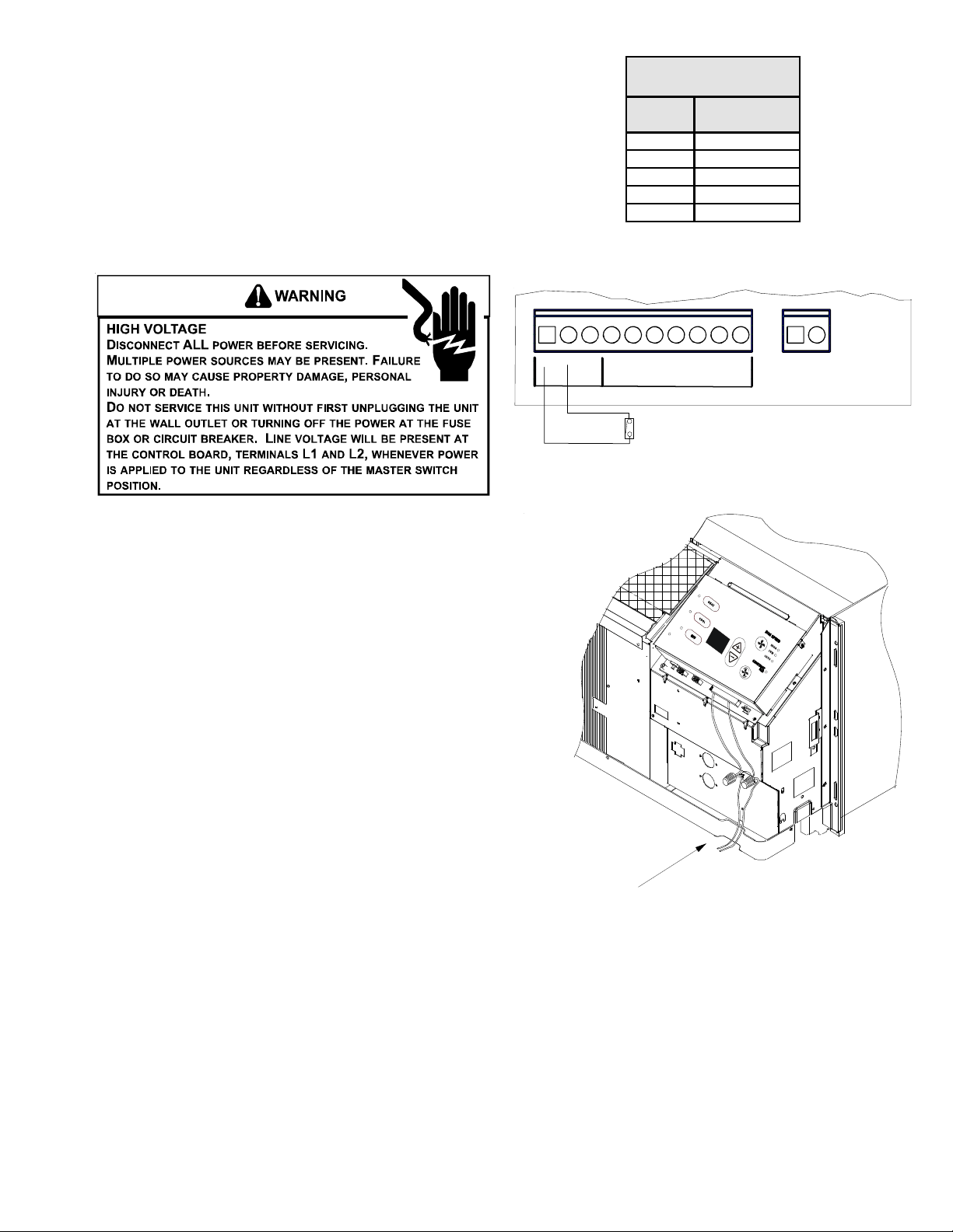
FRONT DESK CONTROL (IN1, IN2, COM)
The COM and IN2 or IN1 terminals provide control inputs for a
front desk switch. Shorting across the terminals will disable unit
operation. The only control function which will remain active
when these terminals are shorted is freeze protection. Any
switch which will produce a short circuit across these two
terminals can be used as a front desk switch. The contact
resistance of the switch, when closed, must be less than 200
ohms for the front desk feature to operate properly. Table 3
shows the maximum wire length and corresponding gage size for
installation of a front desk switch. The following figure shows a
wiring schematic for connecting the front desk switch to the
unit.
If the unit is configured for wired unrented setback energy
management (see Configuration Settings section u8 and u9). If
IN* and COM are shorted, the unit will go into setback tempera-
tures for cooling and heating as configured in c3 and c4 (see
Configuration Settings). Unit operation will be disabled. “Fd”
(see Diagnostic Codes) will appear on the display. This allows the
room to quickly recover to a comfortable temperature when the
room is occupied.
Maximum Wire
Len
g
th
Wire Size
(AWG)
Maximum Length
Allowed
#24 400 ft
#22 600 ft
#20 900 ft
#18 1500 ft
#16 2000 ft
Table 3 - Maximum Wire Length for
Front Desk Switch
IN1
COM
IN2
AUXILIARY
C
RGL
W2 Y/W1 B
GH
REMOTE
THERMOSTAT
IAT
BLACK
FRONT
DESK
SWITCH
Front Desk Switch Wiring Schematic
No holes are permitted in chassis basepan or
wallsleeve when routing low voltage wire. Route the
low voltage wires through the indention on the front
of the basepan.
Low Voltage Wires Routing
Loading ...
Loading ...
Loading ...