Loading ...
Loading ...
Loading ...
7
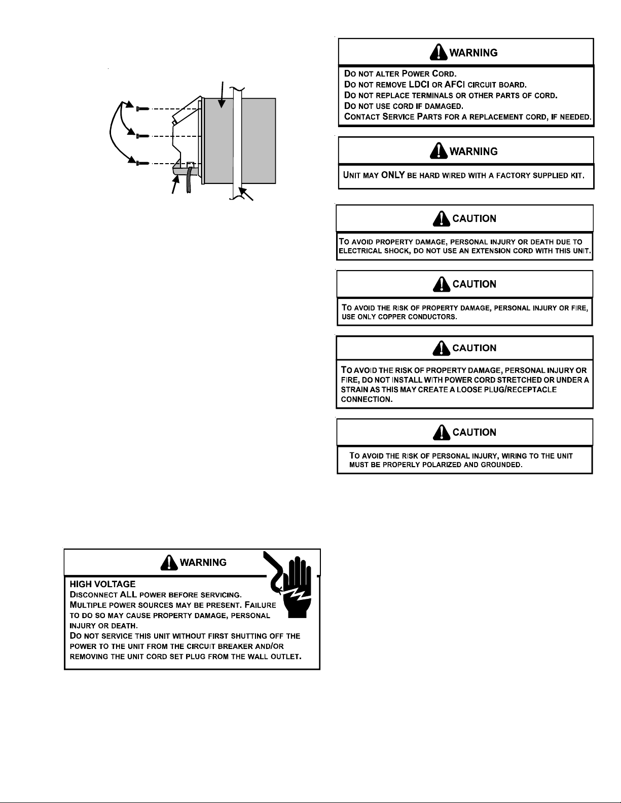
3. Slide the chassis into the wall sleeve until the chassis
flanges contact the front edge of the wall sleeve.
Chassis
Wall Sleeve
Outside
Wall
Screws
(3 on each
side of unit)
Chassis Installation View 2
4. Secure the chassis to the wall sleeve using three screws on
each side of the chassis to ensure a proper seal between
the chassis and the wall sleeve. The screws are supplied
in a plastic bag attached to the power cord.
IMPORTANT NOTES:
1. The unit is equipped with a rubber grommet mounted com-
pressor. These grommets are factory set and require no ad-
justment.
2. If a standard subbase is used, be sure the right hand subbase
cover is removed before the chassis is installed in the sleeve.
3. On 230V, 30A units installed with an existing subbase, use
the subbase cover extension kit.
4. Check the indoor and outdoor grilles for obstructions to air
flow. The unit must be located where curtains, furniture,
trees, or other objects do not block the air flow to and from
the unit. If air is obstructed and/or deflected back into the
unit, the air conditioner compressor may cycle on and off
rapidly. This could damage the compressor or possibly void
the warranty.
WIRING
Cord connection to a wall socket is not permitted for 265-volt
units. All 265-volt units must be hard wired using the hard wire
kit or make use of the plug-in receptacle in the standard
subbase.
230/208V and 115V units are equipped with LCDI or AFCI power
cords and can open the electrical circuit to the unit. In the event
the unit does not operate, check the reset button located on or
near the head of the power cord as part of the normal trouble-
shooting procedure.
Loading ...
Loading ...
Loading ...