Loading ...
Loading ...
Loading ...
16
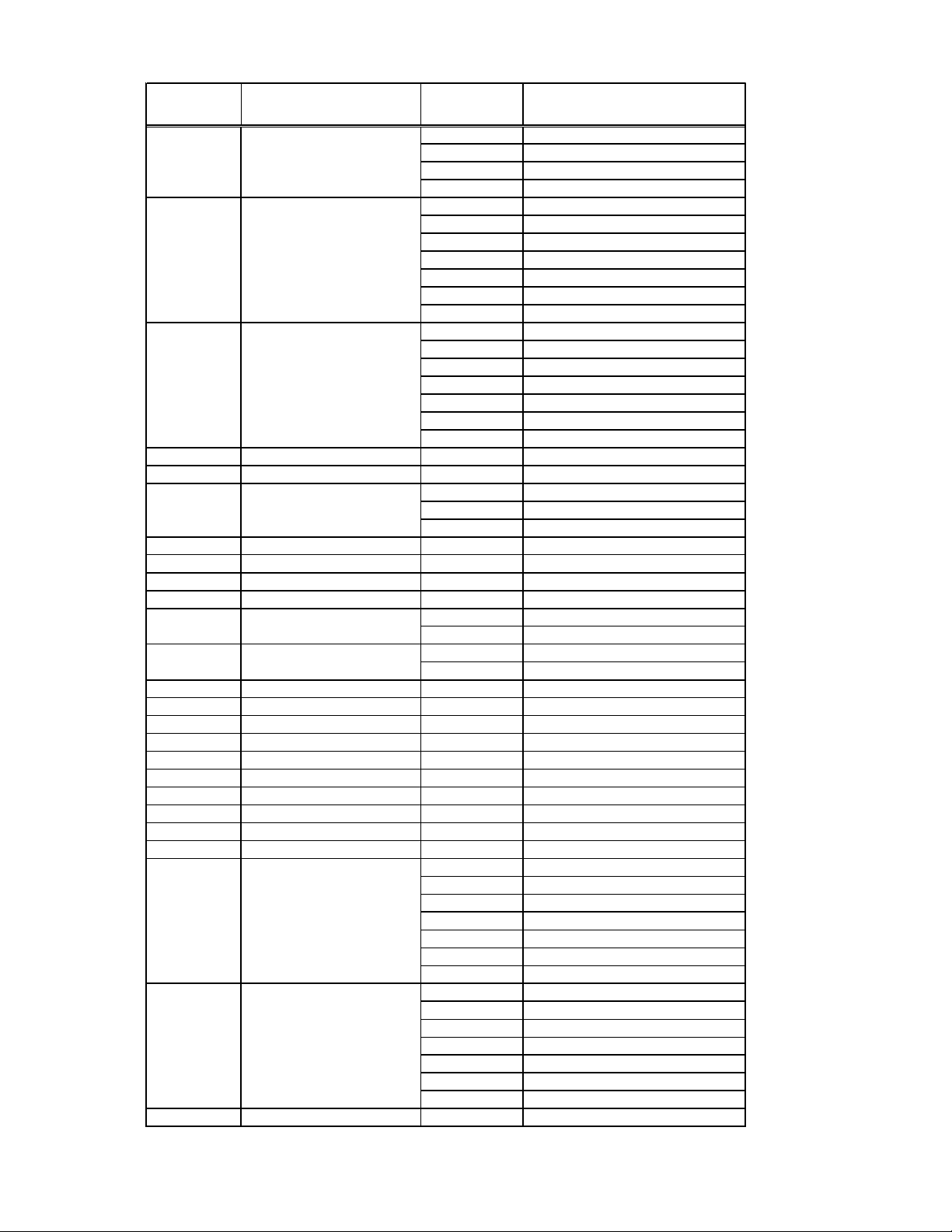
CONFIGURATION SETTINGS CHART
*Indicates factory default
See manufacturer for additional configuration options.
Configuration
Code
Configuration Feature Option Code Option
0 * Chassis Membrane *
L5 Wired Thermostat
rE Wireless Stat & 7-Button
L0 Locked Membrane
Au do not use
On do not use
bP Button present
bA* Revert to Cyclic
A Always run fan (even if Off)
C do not use
bC Revert to Continuous
C Cooler Only PTC
H* Heat Pump PTH *
0 Sevice No Operation "Eo"
dC Dry Cooler DRY
dH do not use
uC MTC Cooler
uH MTH Heat Pump
C4 Room I.D. Digit 1 & 2 00* - 99 00* - 99
C5 Room I.D. Digit 3 & 4 00* - 99 00* - 99
0* Off*
1On
18 18 Hour Automatic Entry
C8 Temp. Limiting Cool 60* - 80 60* - 80
C9 Temp. Limiting Heat 68 - 90, 80* 68 - 90, 80*
c3 Un-rent ClnTemp. 45 - 95, 79* 45 - 95, 79*
c4 Un-rent HtnTemp. 45 - 95, 63* 45 - 95, 63*
0* Not Twinned*
5 Twinned
F* Fahrenheit Scale*
CCelsius Scale
d6 Sensorless Un-Occ. Time 1 - 32, 18* 1 - 32, 18*
d7 1st Un-Occ. Set Back Temp. 1 - 16, 2* 1 - 16, 2*
d8 1st Un-Occ. Set Back Time .1, .5*, 1 - 24 .1 ,.5 ,1 - 24, .5*
d9 2nd Un-Occ. Set Back Temp. 1 - 16, 3* 1 - 16, 3*
dA 2nd Un-Occ. Set Back Time .5, 1* - 24 (d8) - 24, 1*
db 3rd Un-Occ. Set Back Temp. 1 - 16, 6* 1 - 16, 6*
dC 3rd Un-Occ. Set Back Time
1 - 24, 3*
(dA) - 24, 3*
dF Platform Group Code 00* - 99 00* - 99
r4 Room Prefix 00* - 99 00* - 99
r5 Room Suffix 00* - 99 00* - 99
0* Door Switch
1 Motion Sensor
2Front Desk
3 Wired Un-rented Set Back
4Emergency Hydronic
5 Load Shedding
6Alarm Sensor
0* Door Switch
1 Motion Sensor
2Front Desk
3 Wired Un-rented Set Back
4Emergency Hydronic
5 Load Shedding
6Alarm Sensor
uL Config. Security Code 00* - 99 00* - 99
CA Wireless Twin Unit
C1 Interface
C2 ID Fan Operation
C3 Reverse Cycle Operation
C6 Wired Occupancy
u9 Input Pins UN2 & COM
Cd English / Metric Temp
u8 Input Pins UN1 & COM
Loading ...
Loading ...
Loading ...