PMS 419
Owner's Manual
for Maintenance and Safety
2017
ACE™ 570

For videos and more information
about a safe riding experience with
your Polaris vehicle, scan this QR
code with your smartphone.

1
WELCOME
Thank you for purchasing a POLARIS vehicle, and welcome to our
world-wide family of POLARIS enthusiasts. Be sure to visit us online at
www.polaris.com for the latest news, new product introductions,
upcoming events, career opportunities and more.
Here at POLARIS we proudly produce an exciting line of utility and
recreational products.
• Snowmobiles
• All-terrain vehicles (ATVs)
• Low emission vehicles (LEVs)
• RANGER® utility vehicles
• RZR® sport vehicles
• VICTORY® motorcycles
• INDIAN® motorcycles
• GEM® electric vehicles
Always follow the instructions and recommendations in this manual.
The manual contains instructions for minor maintenance, but
information about major repairs is outlined in the POLARIS Service
Manual and should be performed only by a factory-certified Master
Service Dealer® (MSD) technician. Please see your dealer for all of
your service needs during (and after) the warranty period.

2
POLARIS® and ACE™ are trademarks of POLARIS Industries Inc.
Copyright 2016 POLARIS Industries Inc. All information contained within this
publication is based on the latest product information at the time of publication. Due to
constant improvements in the design and quality of production components, some minor
discrepancies may result between the actual vehicle and the information presented in
this publication. Depictions and/or procedures in this publication are intended for
reference use only. No liability can be accepted for omissions or inaccuracies. Any
reprinting or reuse of the depictions and/or procedures contained within, whether whole
or in part, is expressly prohibited.
The original instructions for this vehicle are in English. Other languages are provided as
translations of the original instructions.
2017 POLARIS ACE 570 Owner’s Manual
P/N 9927489

3
TABLE OF CONTENTS
Introduction . . . . . . . . . . . . . . . . . . . . . . . . . . . . 4
Safety . . . . . . . . . . . . . . . . . . . . . . . . . . . . . . . . . 9
Features and Controls. . . . . . . . . . . . . . . . . . . 24
Operation . . . . . . . . . . . . . . . . . . . . . . . . . . . . . 52
Winch Guide . . . . . . . . . . . . . . . . . . . . . . . . . . . 73
Emission Control Systems . . . . . . . . . . . . . . . 84
Maintenance . . . . . . . . . . . . . . . . . . . . . . . . . . . 85
Specifications. . . . . . . . . . . . . . . . . . . . . . . . . 132
POLARIS Products. . . . . . . . . . . . . . . . . . . . . 134
Troubleshooting. . . . . . . . . . . . . . . . . . . . . . . 135
Warranty . . . . . . . . . . . . . . . . . . . . . . . . . . . . . 139
Maintenance Log . . . . . . . . . . . . . . . . . . . . . . 144
Index . . . . . . . . . . . . . . . . . . . . . . . . . . . . . . . . 145

4
INTRODUCTION
This POLARIS vehicle is an off-road vehicle. Familiarize yourself with
all laws and regulations concerning the operation of this vehicle in your
area.
The following signal words and symbols appear throughout this manual
and on your vehicle. Your safety is involved when these words and
symbols are used. Become familiar with their meanings before reading
the manual.
The safety alert symbol indicates a potential personal injury hazard.
DANGER
A DANGER indicates a hazardous situation that, if not avoided, will result in
death or serious injury.
WARNING
A WARNING indicates a hazardous situation that, if not avoided, could result in
death or serious injury.
CAUTION
A CAUTION indicates a hazardous situation that, if not avoided, could result in
minor or moderate injury.
NOTICE
A NOTICE indicates a situation that could result in property damage.
The Prohibition Safety Sign indicates an action NOT to take in order
to avoid a hazard.
The Mandatory Action Sign indicates an action that NEEDS to be
taken to avoid a hazard.

5
INTRODUCTION
Failure to heed the warnings and safety precautions contained in this manual
can result in severe injury or death. Your POLARIS vehicle is not a toy and can
be hazardous to operate. This vehicle handles differently than cars, trucks or
other off-road vehicles. A collision or rollover can occur quickly, even during
routine maneuvers like turning, or driving on hills or over obstacles, if you fail to
take proper precautions.
• Read this owner’s manual and review the safety DVD that came with your
vehicle. A free extra copy of the DVD can be obtained by contacting your local
POLARIS dealer. Understand all safety warnings, precautions and operating
procedures before operating the vehicle. Keep this manual with the vehicle.
• Never operate this vehicle without proper instruction. Take an authorized
training course.
• This vehicle is an ADULT VEHICLE ONLY. You MUST be at least age 16 and
have a valid driver’s license to operate this vehicle.
• Always use the cab nets (or doors) while riding in this vehicle. Always keep
hands, feet and all other body parts inside the vehicle at all times.
• Always wear a helmet, eye protection, gloves, long-sleeve shirt, long pants
and over-the-ankle boots.
• Never use this vehicle with drugs or alcohol, as these conditions impair
judgment and reduce operator reaction time.
• Complete the New Operator Driving Procedures outlined on pages 58-59.
Never allow a guest to operate this vehicle until the guest has completed the
New Operator Driving Procedures.
• Never permit a guest to operate this vehicle unless the guest has reviewed the
owner’s manual and all safety labels and has completed a safety training
course.
WARNING

6
INTRODUCTION
European Vibration and Noise
The driver-perceived noise and hand/arm and whole body vibration levels of this
machinery is measured per EN 15997.
The operating conditions of the machinery during testing:
The vehicles were in like-new condition. The environment was controlled as
indicated by the test procedure(s).
The uncertainty of vibration exposure measurement is dependent on many
factors, including:
• Instrument and calibration uncertainty
• Variations in the machine such as wear of components
• Variation of machine operators such as experience or physique
• Ability of the worker to reproduce typical work during measurements
• Environmental factors such as ambient noise or temperature
7
INTRODUCTION
Declaration of Conformity
Polaris Sales Europe Sàrl
Route de I’Etraz
Business Center A5
1180 Rolle, Switzerland
Telephone +41213-218-700
DECLARATION OF CONFORMITY
January 1, 2016
Polaris Sales Europe Sàrl declares that the vehicle(s)
listed below conform to the essential requirements
applicable to all terrain vehicles.
APPLICABLE EUROPEAN DIRECTIVES: TEST / EVALUATION METHODS
2006/42/EC as amended
(Machinery Directive)
EN ISO 12100:2010 Hazard Analysis
EN 15997:2011/AC:2012 Driver
Perceived
Noise Level & Vibration
2014/30/EU as amended
(EMC Directive)
UNECE R10
MODEL COMMERCIAL NAME SERIAL NUMBER
A_ _DA _ 57_ _
(All combinations)
ACE 570 (See Product Identification
Label)
8
INTRODUCTION
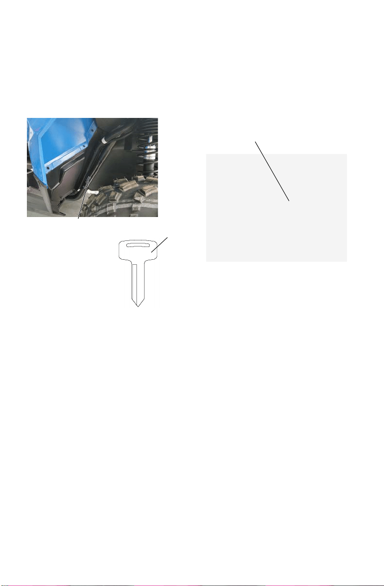
Vehicle Identification Numbers
Record your vehicle's identification numbers and key number in the
spaces provided. Remove the spare key and store it in a safe place. An
ignition key can be duplicated only by ordering a POLARIS key blank
(using your key number) and mating it with one of your existing keys.
The ignition switch must be replaced if all keys are lost.
Vehicle Model Number: ___________________________________________________
Vehicle Identification Number (VIN): _________________________________________
Engine Serial Number: ___________________________________________________
Key Number____________________________________________________________
Engine Serial
Number
Key
Number
VIN
(Right Front Frame)
####

9
SAFETY
Safety Training
Safety training is a top priority for POLARIS. POLARIS strongly
encourages you and any family members who will be riding this vehicle
to take a training course.
For more information about safety, contact an authorized POLARIS
dealer or visit the POLARIS web site at www.polaris.com.
Your POLARIS vehicle is considered an off-road vehicle. Familiarize
yourself with all laws and regulations concerning the operation of this
vehicle in your area.
We strongly advise you to strictly follow the recommended maintenance
program outlined in your owner's manual. This preventive maintenance
program is designed to ensure that all critical components on your
vehicle are thoroughly inspected at specific intervals.
10
SAFETY
Safe Riding Gear
Always wear helmet, eye protection, gloves, long-sleeve shirt, long
pants, over-the-ankle boots and seat belt at all times. Protective gear
reduces the chance of injury.
Helmet
Wearing a helmet can prevent a severe head injury. Whenever riding this
POLARIS vehicle, always wear a helmet that meets or exceeds
established safety standards.
Approved helmets in the USA and Canada bear a
U.S. Department of Transportation (DOT) label.
Approved helmets in Europe, Asia and Oceania
bear the ECE 22.05 label. The ECE mark consists
of a circle surrounding the letter E, followed by the
distinguishing number of the country which has
granted approval. The approval number and serial number will also be
displayed on the label.
E
4
051039
0006.31
Helmet
Eye Protection
Gloves
Over-the-Ankle
Boots
Long Pants
Long
Sleeves

11
SAFETY
Safe Riding Gear
Eye Protection
Do not depend on eyeglasses or sunglasses for eye protection.
Whenever riding this POLARIS vehicle, always wear shatterproof
goggles or use a shatterproof helmet face shield. POLARIS
recommends wearing approved Personal Protective Equipment (PPE)
bearing markings such as VESC 8, V-8, Z87.1, or CE. Make sure
protective eye wear is kept clean.
Gloves
Wear gloves for comfort and for protection from sun, cold weather and
other elements.
Boots
Wear sturdy over-the-ankle boots for support and protection. Never ride
a POLARIS vehicle with bare feet or sandals.
Clothing
Wear long sleeves and long pants to protect arms and legs.
Rider Comfort
Under certain operating conditions, heat generated by the engine and
exhaust system can elevate temperatures in the rider cab area. The
condition occurs most frequently when a vehicle is being operated in
high ambient temperatures at low speeds and/or high load conditions for
an extended period of time. The use of certain windshield, roof and/or
cab systems may contribute to this condition by restricting airflow. Any
discomfort due to heat buildup in this area can be minimized by wearing
proper riding apparel and by varying speeds to increase airflow.
12
SAFETY
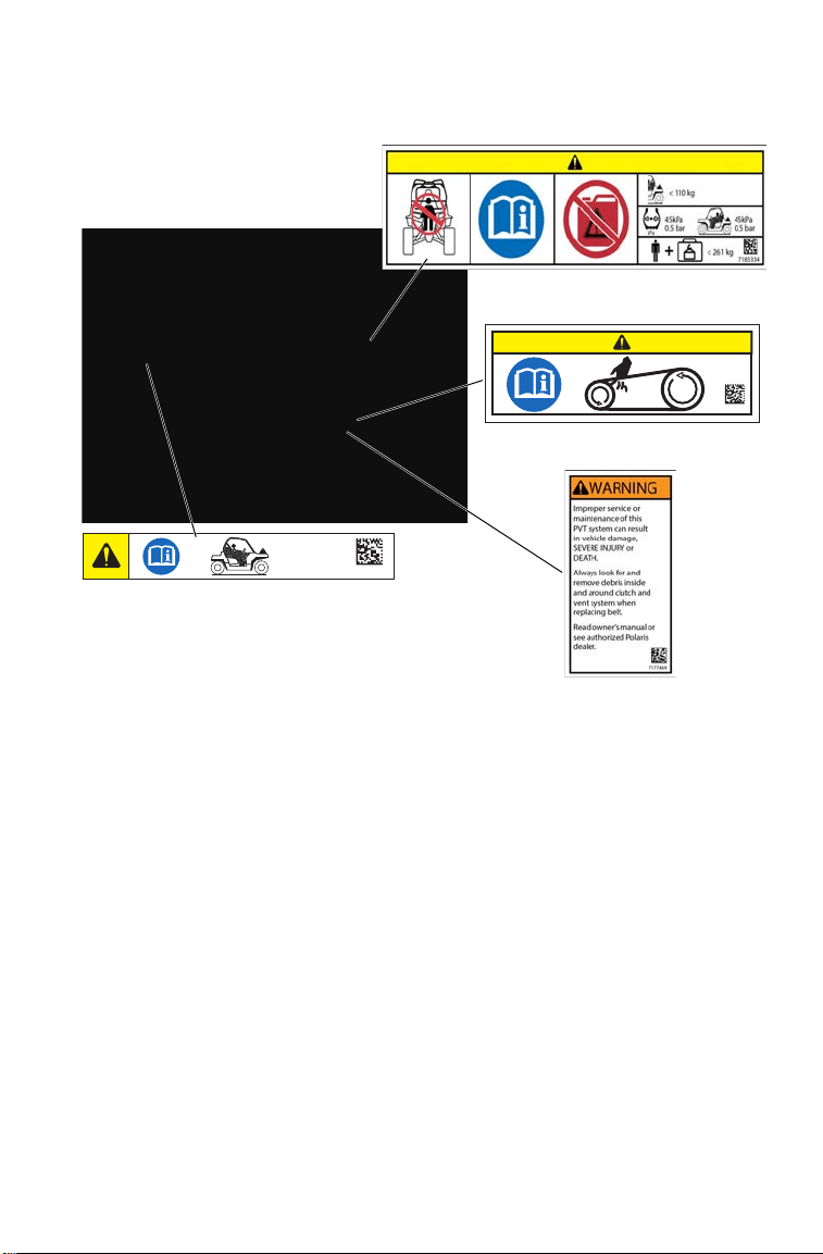
Safety Labels and Locations
Warning labels have been placed on the vehicle for your protection.
Read and follow the instructions of the labels on the vehicle carefully. If
any of the labels depicted in this manual differ from the labels on your
vehicle, always read and follow the instructions of the labels on the
vehicle.
If an informational or graphic label becomes illegible or comes off,
contact your POLARIS dealer to purchase a replacement. Replacement
safety labels are provided by POLARIS at no charge. The part number is
printed on the label.
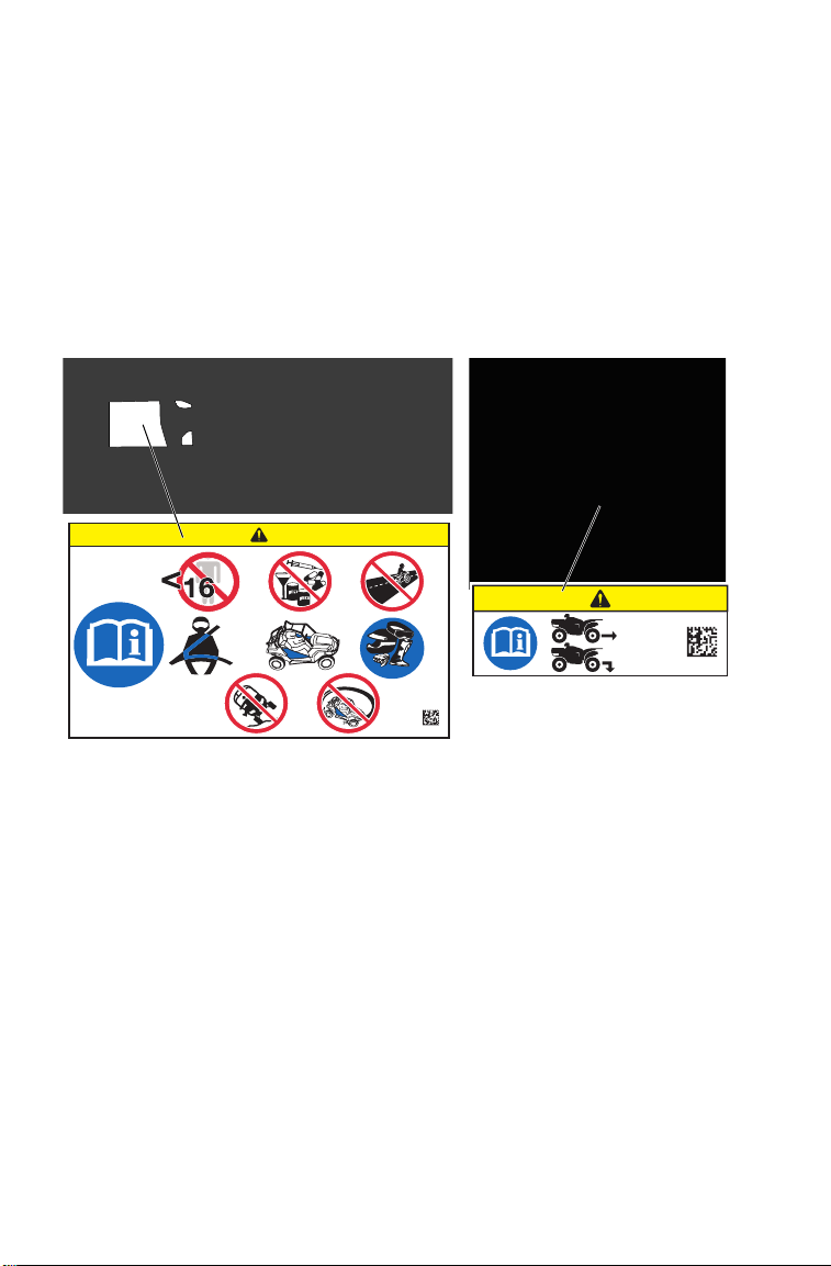
General Alert (7182088)
Before you operate this vehicle, read the owner’s manual. Never allow anyone
under 16 years of age to operate this vehicle. Never use alcohol or drugs before
or while operating. Never operate the vehicle on any public street, road or
highway. Always wear the seat belt. Always use the cab nets (or doors) while
riding in this vehicle. Wear approved helmet, goggles, and protective clothing.
Never carry a passenger on this vehicle. Vehicle rollover could cause severe
injury or death. Always avoid operating in a manner that could result in vehicle
rollover. Avoid exhibition driving.
Hitch Capacity Label (7182091)
Trailer Maximum Weight: 680 kg (on level ground)
Hitch Maximum Vertical Weight: 68 kg
7182088
General Alert
680 kg
68 kg
7182091
Hitch Capacity Alert
13
SAFETY
Safety Labels and Locations
Passenger/Tire Pressure Alert (7182090)
Read Operation and Maintenance Manual for more detailed loading information.
Do not carry a passenger in the cargo box.
Maximum Cargo Box Load: 110 kg
Tire Pressure: 45 kPa
Maximum Weight Capacity
(including weight of operator, cargo and accessories: 261 kg
Front Compartment Storage Capacity Alert (7182092)
Maximum Weight Capacity: 55 kg
Clutch Cover Alert (7181427)
Keep body parts away from belt.
7182092
< 55 kg
Storage Capacity Alert
(on access cover under rack)
Passenger/Tire Pressure Alert
Clutch Cover Alert
7181427
14
SAFETY
Safety Warnings
Failure to operate this vehicle properly can result in a collision, loss of control,
accident or rollover, which may result in serious injury or death. Heed all safety
warnings outlined in this section of the owner’s manual and in the safety DVD
provided with your vehicle. See the OPERATION section of the owner’s manual
for proper operating procedures.
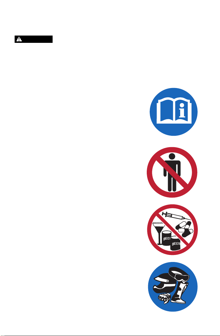
Operating Without Instruction
Operating this vehicle without proper instruction
increases the risk of an accident. Complete the
New Operator Driving Procedures outlined on
pages 58-59.
All operators must read and understand the owner's
manual and all warning and instruction labels
before operating the vehicle. Never allow a guest to
operate this vehicle until the guest has completed
the New Operator Driving Procedures outlined on
pages 58-59.
Age Restrictions
This vehicle is an ADULT VEHICLE ONLY.
Operation is prohibited for anyone under 16 years
of age or anyone without a valid driver’s license.
The operator must be tall enough to sit with back
against the seat, both feet flat on the floor and both
hands on the steering wheel.
Using Alcohol or Drugs
Operating this vehicle after consuming alcohol or
drugs could adversely affect operator judgment,
reaction time, balance and perception.
Never consume alcohol or drugs before or while
operating this vehicle.
Protective Apparel
Riding in this vehicle without wearing an approved
helmet and protective eyewear increases the risk of
a serious injuries in the event of an accident.
Always wear a helmet, eye protection, gloves, long-
sleeve shirt, long pants and over-the-ankle boots.
WARNING
<
16
15
SAFETY
Safety Warnings
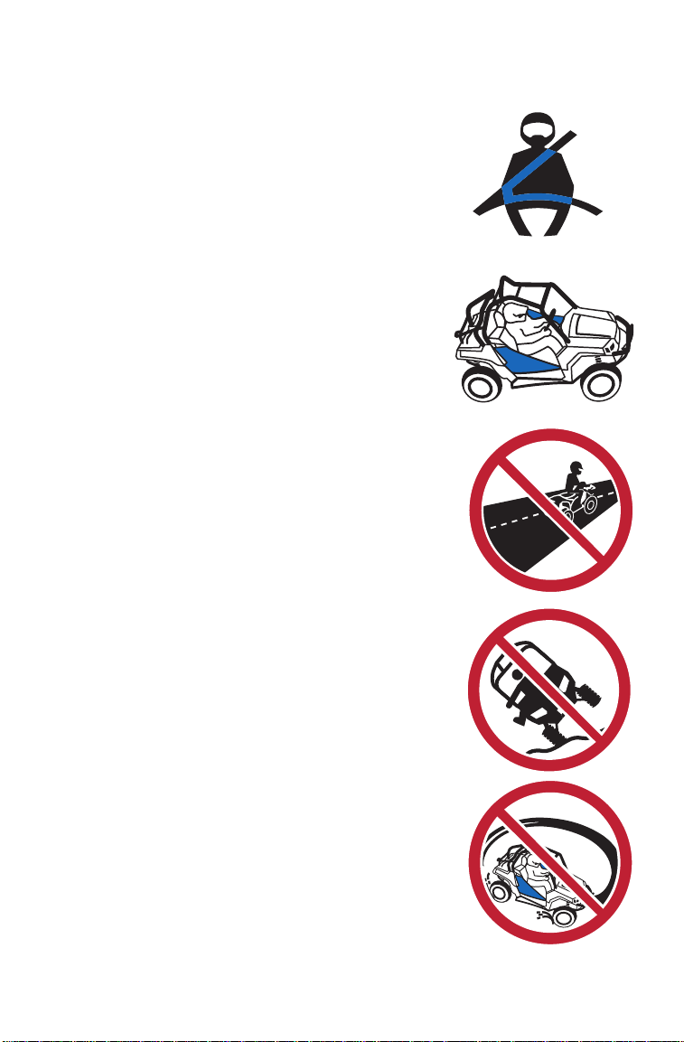
Seat Belts
Riding in this vehicle without wearing the seat
belt increases the risk of serious injury in the
event of rollover, loss of control, other accident
or sudden stop. Seat belts may reduce the
severity of injury in these circumstances.
The operator MUST wear the seat belt at all
times.
Cab Nets
Riding in this vehicle without using the cab nets
(or doors, if equipped) increases the risk of
serious injury or death in the event of an
accident or rollover. Always use the cab nets
(or doors) while riding in this vehicle. Always
keep hands and feet inside the vehicle at all
times.
Operating on Public Roads
Operating this vehicle on public streets, roads
or highways could result in a collision with
another vehicle. Always heed all local laws
and regulations governing the operation of
this vehicle.
Rollovers
A rollover can result in serious injury or death.
Avoid operating in a manner that could result
in a rollover.
Jumps and Stunts
Exhibition driving increases the risk of an
accident or rollover. DO NOT do power slides,
“donuts”, jumps or other driving stunts. Avoid
exhibition driving.
16
SAFETY
Safety Warnings
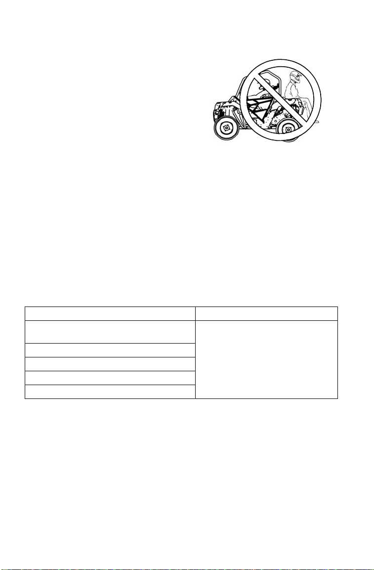
Carrying a Passenger
This POLARIS vehicle is a single-rider
vehicle. Carrying a passenger greatly
reduces the operator's ability to control
the vehicle, which may result in an
accident or rollover. Carrying a
passenger in the cargo box could result
in a fall from the vehicle or contact with
moving components. Never carry a
passenger on this vehicle.
Operating With a Load on the Vehicle
The weight of both cargo and operator impacts vehicle operation and stability.
For your safety and the safety of others, carefully consider how your vehicle is
loaded and how to safely operate the vehicle. Follow the instructions in this
manual for loading, tire pressure, gear selection and speed.
• Do not exceed vehicle weight capacities. The vehicle’s maximum weight
capacity is listed in the specifications section of this manual and on a label on
the vehicle. When determining the weight you are adding to the vehicle,
include the weight of the operator, accessories, loads in the rack or box and
the load on the trailer tongue. The combined weight of these items must not
exceed the maximum weight capacity.
• The recommended tire pressures are listed in the specifications section of this
manual and on a label on the vehicle.
Always follow these guidelines:
Under ANY of these conditions: Do ALL of these steps:
Operator and/or cargo exceeds half the
maximum weight capacity
1. Slow down.
2. Verify tire pressure.
3. Use extra caution when
operating.
Operating in rough terrain
Operating over obstacles
Climbing an incline
Towing
17
SAFETY
Safety Warnings
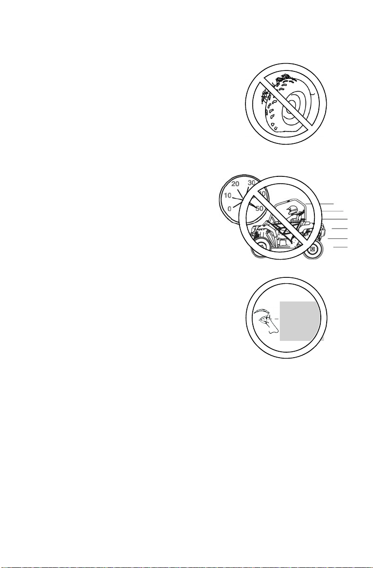
Improper Tire Maintenance
Operating this vehicle with improper tires or
with improper or uneven tire pressure could
cause loss of control or accident.
Always use the size and type of tires specified
for your vehicle.
Always maintain proper tire pressure as
described in the owner's manual and on safety
labels.
Operating at Excessive Speeds
Operating this vehicle at excessive speeds
increases the operator's risk of losing
control. Always operate at a speed that's
appropriate for the terrain, the visibility and
operating conditions and your skills and
experience.
Failure to Inspect Before
Operating
Failure to inspect and verify that the vehicle
is in safe operating condition before
operating increases the risk of an accident.
Always perform the pre-ride inspection
before each use of your vehicle to make
sure it's in safe operating condition. See
page 54.
Always follow the inspection and maintenance procedures and schedules
described in this owner’s manual. See page 85.

18
SAFETY
Safety Warnings
Turning Improperly
Turning improperly could cause loss of traction, loss of control, accident or
rollover. Always follow proper procedures for turning as described in this
owner’s manual.
Avoid sharp turns. Never turn while applying heavy throttle. Never make abrupt
steering maneuvers. Practice turning at slow speeds before attempting to turn at
faster speeds.
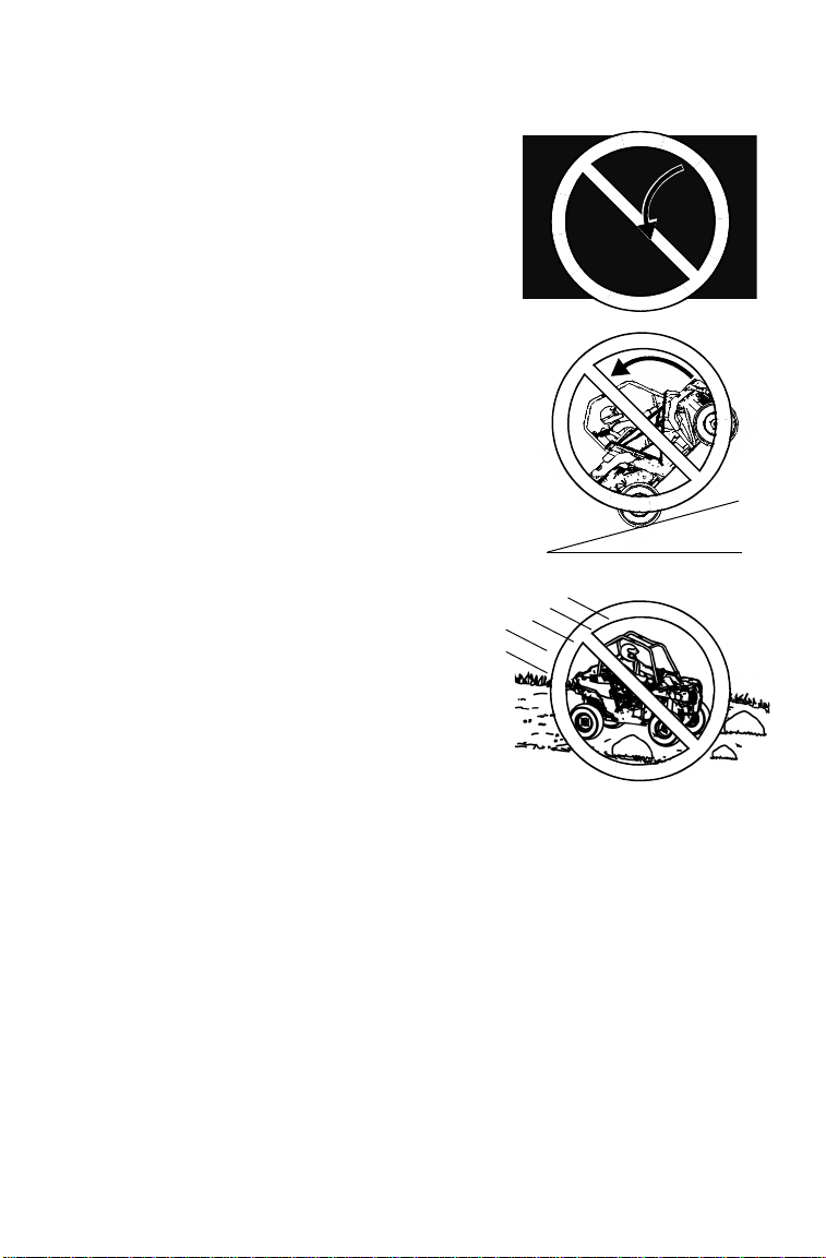
Improper Hill Climbing
Improper hill climbing could cause loss of
control or rollover. Use extreme caution when
operating on hills. Always follow proper
procedures for hill climbing as described in this
owner's manual. See page 62.
Descending Hills Improperly
Improperly descending a hill could cause loss
of control or rollover. Always follow proper
procedures for traveling down hills as described
in this owner’s manual. See page 64.
19
SAFETY
Safety Warnings
Crossing Hillsides
Driving on a sidehill is not recommended.
Improper procedure could cause loss of
control or rollover. Avoid crossing the side of
any hill unless absolutely necessary.
If crossing a hillside is unavoidable, always
follow proper procedures as described in this
owner's manual. See page 63.
Stalling While Climbing a Hill
Stalling or rolling backwards while climbing a
hill could cause a rollover. Maintain a steady
speed when climbing a hill.
If you lose all forward speed:
Apply the brakes gradually until the vehicle
is fully stopped. Place the transmission in
reverse and slowly allow the vehicle to roll
straight downhill while applying light brake
pressure to control speed.
Operating in Unfamiliar Terrain
Failure to use extra caution when operating
on unfamiliar terrain could result in an
accident or rollover.
Unfamiliar terrain may contain hidden rocks,
bumps, or holes that could cause loss of
control or rollover.
Travel slowly and use extra caution when
operating on unfamiliar terrain. Always be
alert to changing terrain conditions.
20
SAFETY
Safety Warnings
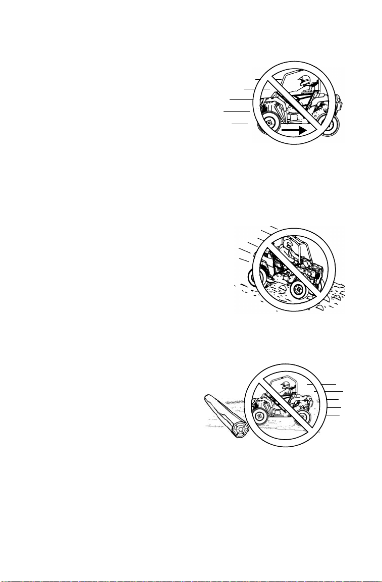
Operating Improperly in Reverse
Improperly operating in reverse could result in a
collision with an obstacle or person. Always
follow proper operating procedures as outlined
in this manual. See page 67.
Before shifting into reverse gear, always check
for obstacles or people behind the vehicle.
When it's safe to proceed, back slowly.
Improper Tire Maintenance
Operating this vehicle with improper tires or with improper or uneven tire
pressure could cause loss of control, accident or rollover.
Always use the size and type of tires specified for your vehicle. Always maintain
proper tire pressure as described in this owner's manual and on safety labels.
Skidding or Sliding
Failure to use extra caution when operating on
excessively rough, slippery or loose terrain
could cause loss of traction, loss of control,
accident or rollover. Do not operate on
excessively slippery surfaces. Always slow
down and use additional caution when
operating on slippery surfaces.
Skidding or sliding due to loss of traction can
cause loss of control or rollover (if tires regain
traction unexpectedly). Always follow proper
procedures for operating on slippery surfaces
as described in this owner's manual. See page 61.
Operating Over Obstacles
Improperly operating over obstacles
could cause loss of control or rollover.
Before operating in a new area, check
for obstacles. Avoid operating over
large obstacles such as large rocks and
fallen trees. Always follow the proper
procedures outlined in this manual
when operating over obstacles. See
page 66.
21
SAFETY
Safety Warnings
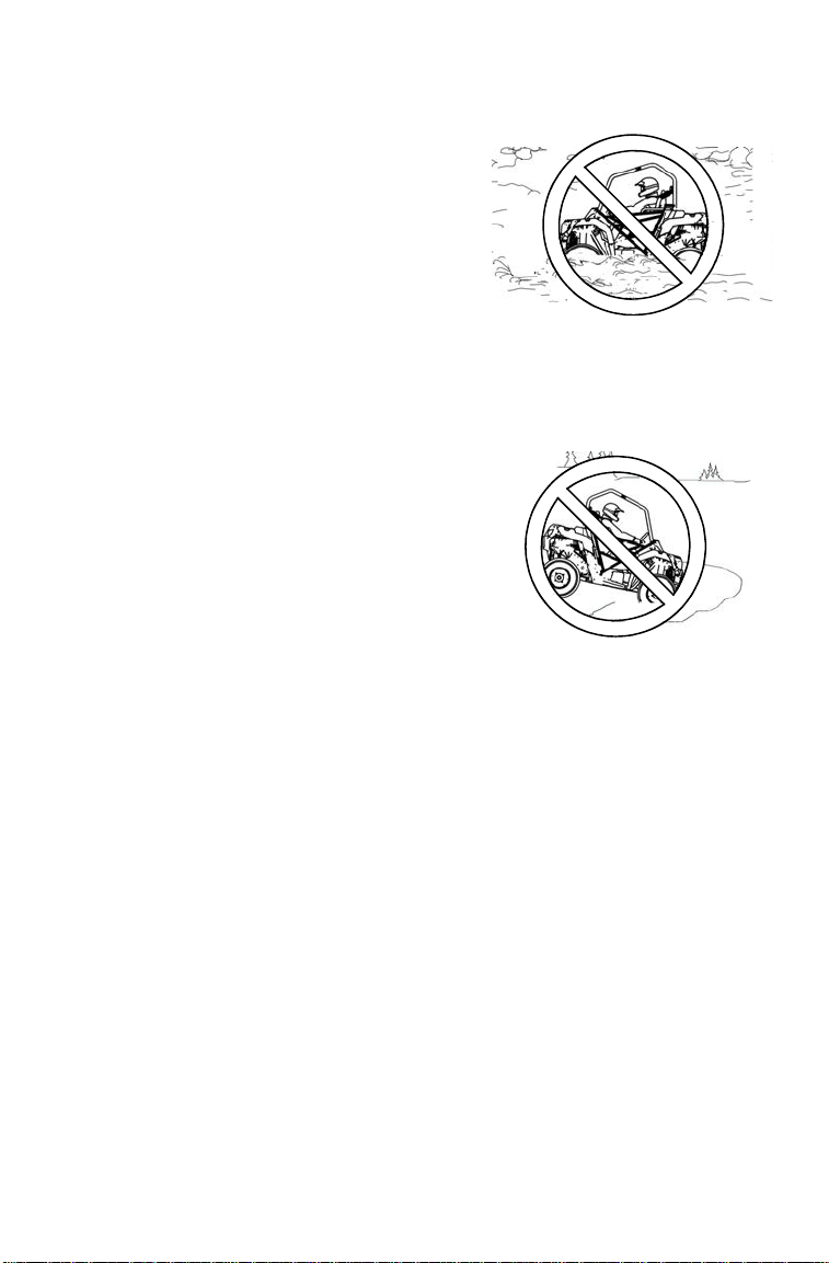
Operating Through Water
Operating through deep or fast-flowing
water can cause loss of traction, loss of
control, rollover or accident. Never operate
in fast-flowing water or in water that
exceeds the floor level of the vehicle.
Always follow proper procedures for
operating in water as described in this
owner’s manual. See page 65.
Wet brakes may have reduced stopping
ability. After leaving water, test the brakes. Apply them lightly several times while
driving slowly. The friction will help dry out the pads.
Operating on Frozen Bodies of Water
Severe injury or death can result if the
vehicle and/or the operator fall through the
ice. Never operate the vehicle on a frozen
body of water unless you have first verified
that the ice is sufficiently thick to support
the weight and moving force of the vehicle,
you and your cargo, together with any
other vehicles in your party.
Always check with local authorities and
residents to confirm ice conditions and
thickness over your entire route. Vehicle
operators assume all risk associated with
ice conditions on frozen bodies of water.
Operating a Damaged Vehicle
Operating a damaged vehicle can result in an accident. After any rollover or
other accident, have a qualified service dealer inspect the entire machine for
possible damage, including (but not limited to) seat belts, rollover protection
devices, brakes, throttle and steering systems.

22
SAFETY
Safety Warnings
Improper Cargo Loading
Overloading the vehicle or carrying/towing cargo improperly may cause
changes in stability and handling, which could cause loss of control or an
accident.
• Always follow the instructions in this owner’s manual for carrying cargo. See
page 68.
• Never exceed the stated load capacity for this vehicle. See page 13.
• Cargo should be properly distributed and securely attached. See page 68.
• Reduce speed when carrying cargo or pulling a trailer. Allow a greater distance
for braking.
Poor Visibility
Operating this vehicle in darkness or inclement weather could result in a
collision or accident, especially if operating on a road or street. This vehicle is
not equipped with highway-approved lights. Operate this vehicle off-road only.
Use caution and drive at reduced speeds in conditions of reduced visibility such
as fog, rain and darkness. Clean headlights frequently and replace burned out
headlamps promptly.
Refueling
Gasoline is highly flammable and explosive under certain conditions.
• Always exercise extreme caution whenever handling gasoline.
• Always turn off the engine when refueling.
• Always refuel outdoors or in a well ventilated area free of any source of flame
or sparks.
• Always use an approved gasoline container to store fuel and remove the
container from the vehicle before filling to avoid fuel ignition due to electrical
static discharge.
• Do not smoke or allow open flames or sparks in or near the area where
refueling is performed or where gasoline is stored.
• Do not overfill the tank. Do not fill the tank neck.
• If gasoline spills on your skin or clothing, immediately wash it off with soap and
water and change clothing.

23
SAFETY
Safety Warnings
Exposure to Exhaust
Engine exhaust fumes are poisonous and can cause loss of consciousness or
death in a short time. Never start the engine or let it run in an enclosed area.
Operate this vehicle only outdoors or in well-ventilated areas.
Hot Exhaust Systems
Exhaust system components are very hot during and after use of the vehicle.
Hot components can cause burns and fire. Do not touch hot exhaust system
components. Always keep combustible materials away from the exhaust
system. Use caution when traveling through tall grass, especially dry grass, to
avoid debris build-up around the exhaust system.
Unauthorized Use of the Vehicle
Leaving the keys in the ignition can lead to unauthorized use of the vehicle by
someone under the age of 16, without a drivers license, or without proper
training. This could result in an accident or rollover. Always remove the ignition
key when the vehicle is not in use.
Equipment Modifications
Your POLARIS vehicle is designed to provide safe operation when used as
directed. Modifications to your vehicle may negatively impact vehicle stability.
Failure of critical machine components may result from operation with any
modifications, especially those that increase speed or power. This vehicle may
become less stable at speeds higher than those for which it is designed. Loss of
control may occur at higher speeds.
Do not install any non-POLARIS-approved accessory or modify the vehicle for
the purpose of increasing speed or power. Any modifications or installation of
non-POLARIS-approved accessories could create a substantial safety hazard
and increase the risk of bodily injury.
The warranty on your POLARIS vehicle will be terminated if any non-POLARIS-
approved equipment and/or modifications have been added to the vehicle that
increase speed or power.
The addition of certain accessories, including (but not limited to) mowers,
blades, tires, sprayers, or large racks, may change the handling characteristics
of the vehicle. Use only POLARIS-approved accessories, and familiarize
yourself with their function and effect on the vehicle.
For more information about safety, contact an authorized POLARIS
dealer or visit the POLARIS web site at www.polaris.com.
24
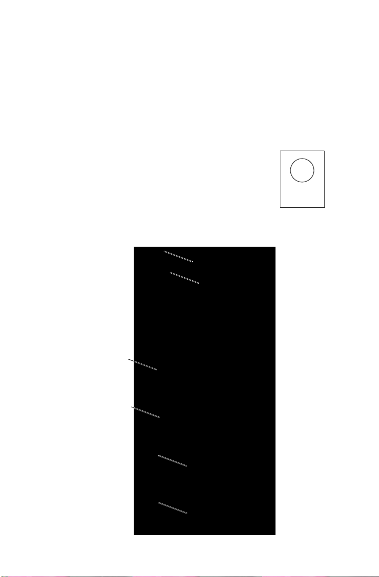
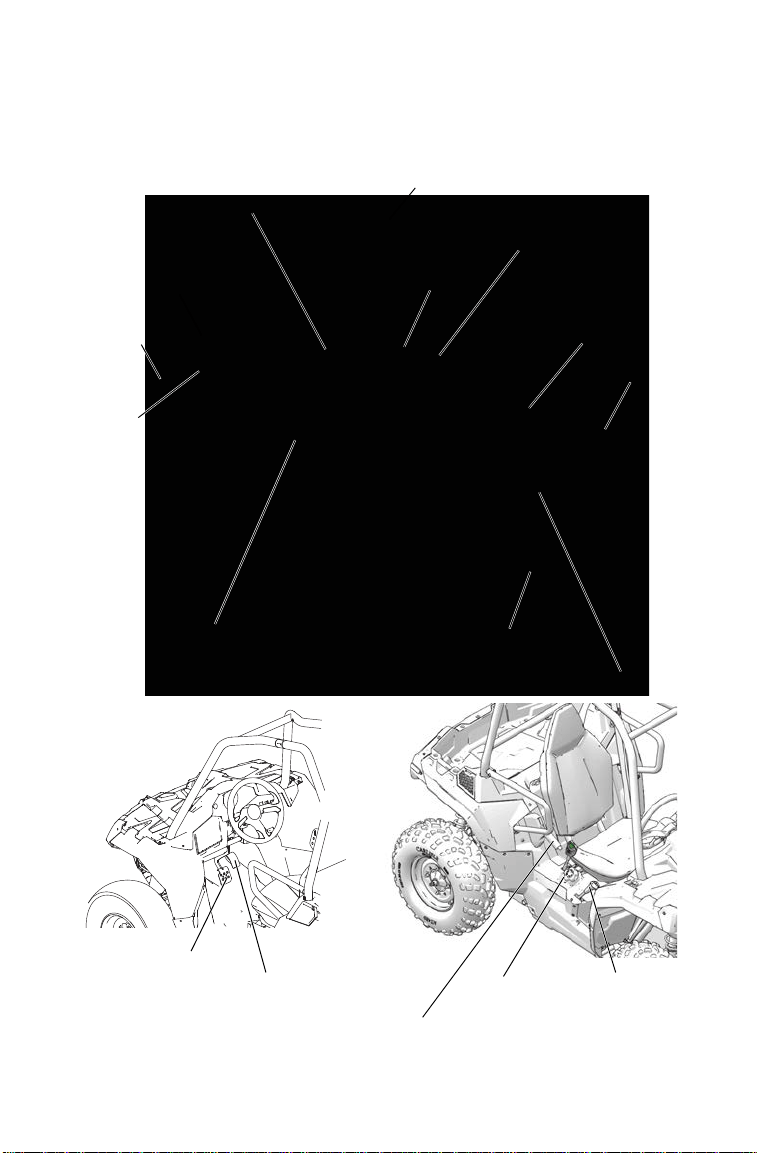
FEATURES AND CONTROLS
Component Locations
Hip
Bars
Cargo
Box
Shifter
Cab Nets
Steering
Wheel
Throttle
Pedal
Brake
Pedal
ROPS
Frame
Front Box
Cover
Headlights
Taillights
Engine
Intake
Pre-Filter
Radiator
Single-Rider
Seat
Brush Guard
Fuel Cap
Park Brake
25
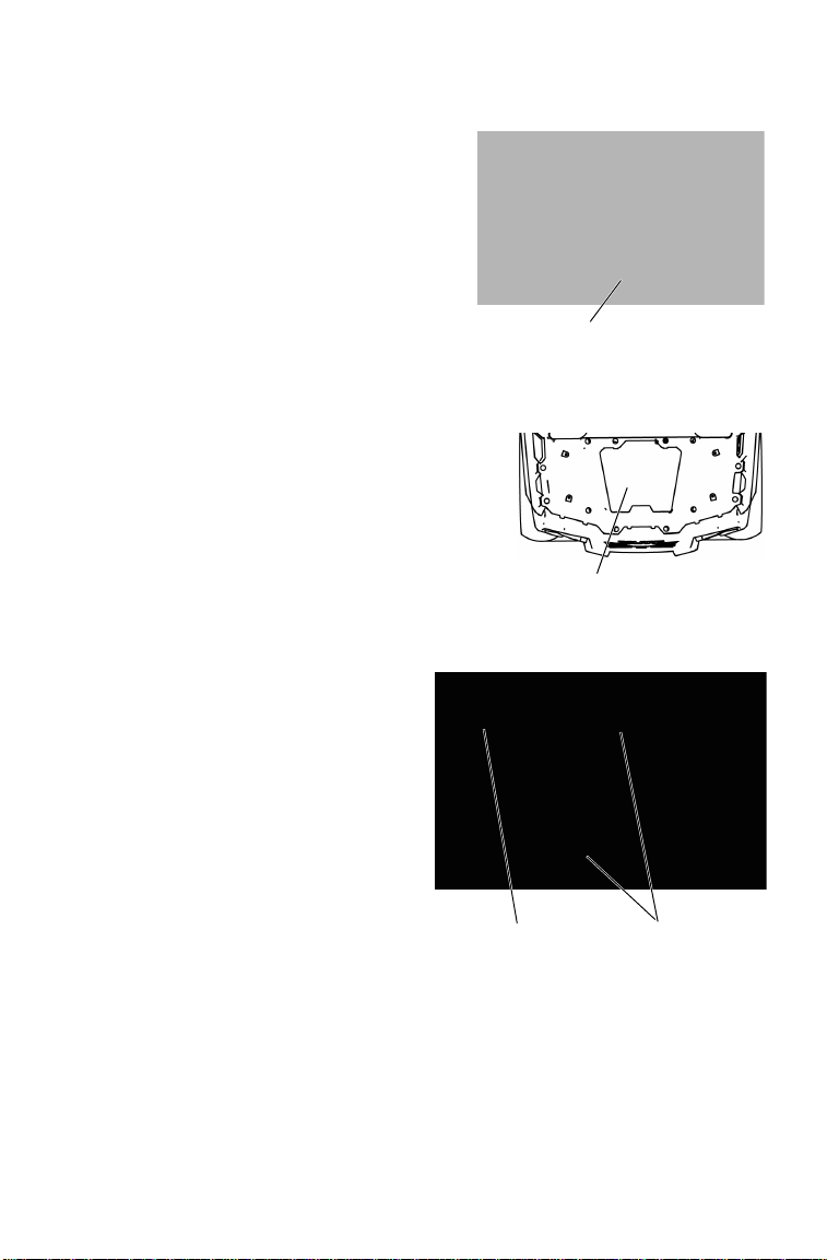
FEATURES AND CONTROLS
Trailer Receiver Hitch Bracket
This vehicle is equipped with a
receiver hitch bracket for a trailer
hitch. Trailer towing equipment is not
supplied with this vehicle.
To avoid injury and property damage,
always heed the warnings and towing
capacities outlined on pages 68-70.
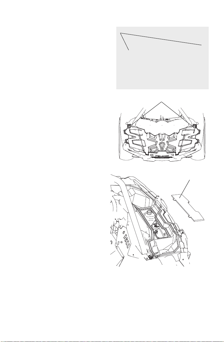
Service Access Panels
Access serviceable engine
components through the engine access
panel behind the seat. Remove the seat
and release the access panel latches to
remove the access panel.
Remove rear access panel to access the
air box and spark plug. The rear access
panel is located in the bed of the cargo
box. Pull the rear edge of the access
panel upward to remove it.
Radiator Access/Bumper Removal
The front bumper can be
removed to clean debris from
the radiator.
1. Remove the four (4) torx
screws and six (6) plastic
rivets.
2. Lift the front bumper to
remove it from the vehicle.
Receiver Hitch
Rear Access Panel
Screws
Rivet

26
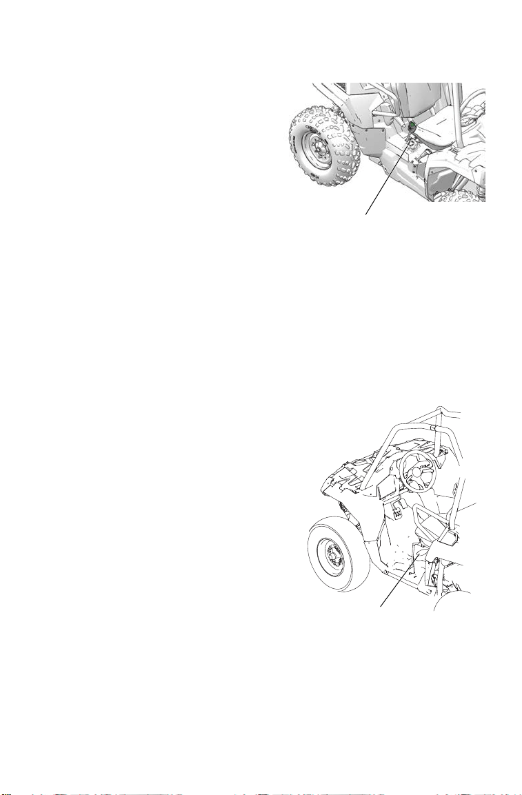
FEATURES AND CONTROLS
Steering Lock
Lock the steering to prevent unauthorized use or theft of the vehicle.
WARNING! Always unlock the steering before starting the engine.
NOTICE: Always remove the steering lock key before operating the vehicle.
Place the steering lock keys in a safe place. The lock must be
replaced if the keys are lost.
1. Turn the steering wheel full right or full left.
2. Open the steering lock cap.
Insert the steering lock key and
turn it clockwise.
3. Continue applying light
clockwise pressure to the key
while moving the steering
wheel slowly in the reverse
direction. When you feel a click
and slight movement of the key,
the steering has locked. Attempt
to move the steering wheel to
verify that it’s locked.
4. Remove the key. Reinstall the steering lock cap.
5. To unlock the steering, insert the steering lock key and turn it
counter-clockwise. Remove the key.
Steering Wheel
The steering wheel can be tilted
upward or downward for rider
preference.
Lift and hold the steering wheel
adjustment lever while moving the
steering wheel upward or
downward. Release the lever when
the steering wheel is at the desired
position.
Always make sure the steering
wheel position does not impede
proper operation of the brake pedal,
throttle pedal and all other controls.
Steering
Lock
Steering
Lock Cap
Adjustment Lever
27
FEATURES AND CONTROLS
Mirrors
Use the mirrors to assist in
traffic maneuvers. Always
check and adjust the mirrors
before driving the vehicle.
Front Box Cover
Remove the front box cover
and access panel to access the
radiator cap, coolant overflow
bottle and brake master
cylinder reservoir.
1. Turn the box cover
fasteners 1/4 turn.
2. Lift the rear edge of the
box cover.
3. Using the pliers provided
in the tool kit, remove the
two (2) push darts from
the access panel. Remove
the panel.
Mirrors
Cover Fasteners
Access Panel

28
FEATURES AND CONTROLS
Cab Nets
Riding in this vehicle
without using the cab
nets (or doors, if
equipped) increases the
risk of serious injury or
death in the event of an
accident or rollover. Cab
nets (or doors) must be
used at all times. Make
sure all latches on both
sides of the vehicle are
secure before operating
the vehicle.
Always inspect cab nets and latches for tightness, wear and damage
before each use of the vehicle. Use the strap adjusters to tighten any
loose straps. Promptly replace worn or damaged cab nets and latches
with new cab nets and latches. Please see your authorized POLARIS
dealer.
Extreme Use Battery
An optional extreme use battery may be available for your model. If the
performance of the factory-installed battery is inadequate due to
operation in extreme cold or due to extended use of multiple electrical
accessories, please see your POLARIS dealer. Ask your dealer to
provide any installation procedures that may differ for an extreme use
battery.
Cab Net Latches
29
FEATURES AND CONTROLS
Fuel Cap
The fuel tank filler cap is located on
the right side of the vehicle near the
seat. When refueling, always use
either leaded or unleaded gasoline
with a minimum pump octane
number of 87 R+M/2 octane. Do
not use fuel with ethanol content
greater than 10 percent, such as E-
85 fuel.
Seat
Seat Adjustments
Always make sure the seat position allows for proper access and
operation of the brake pedal, throttle pedal and all other controls.
The seat release lever is located at the left side of the seat. Push the
release lever downward and slide the seat forward or rearward to the
desired position. Release the lever. The seat will lock into the new
position.
Seat Removal
1. Push the seat release lever
downward and slide the seat
forward until it slides off the
frame.
2. Lift the seat away from the
vehicle.
3. Reverse the procedure to reinstall
the seat.
Fuel Cap
Seat Release
Lever

30
FEATURES AND CONTROLS
Seat Belt
This POLARIS vehicle is equipped with three-point lap and diagonal
seat belts. Always secure the seat belt before riding.
To wear the seat belt properly, follow this procedure:
1. Pull the seat belt latch downward and across your chest toward the
buckle at the inner edge of the seat. The belt should fit snugly across
your hips and diagonally across your chest. Make sure the belt is not
twisted.
2. Push the latch plate into the buckle until it clicks.
3. Release the strap, it will self-tighten.
4. Press the red release latch on the buckle to release the seat belt.
Seat Belt Inspection
Inspect all seat belts for proper operation before each use of the vehicle.
1. Push the latch plate into the buckle until it clicks. The latch plate
must slide smoothly into the buckle. A click indicates that it's
securely latched.
2. Push the red release latch in the middle of the buckle to make sure it
releases freely.
3. Pull each seat belt completely out and inspect the full length for any
damage, including cuts, wear, fraying or stiffness. If any damage is
found, or if the seat belt does not operate properly, have the seat belt
system checked and/or replaced by an authorized POLARIS dealer.
4. To clean dirt or debris from the
seat belts, sponge the straps
with mild soap and water. Do
not use bleach, dye or
household detergents. Use a
garden hose to flush out the
retractor and latch housing
regularly.
Retractor
Housing
Latch
Housing

31
FEATURES AND CONTROLS
Switches
Turn Signal Lever
Before turning, activate a turn
signal to alert others of your
intentions. Check turn signal
lamps before each ride.
Tip: The key must be in the ON
position to activate the turn
signals.
Move the turn signal lever
downward to signal a left
turn. The left turn signal
lamps in the taillight and
below the front headlight will
flash. The turn signal
indicator in the gauge will
also flash.
Move the lever upward to signal a right turn. The right signal lamps and
indicator will flash.
Return the lever to the center position to end the signal.
High Beam Switch
The headlight high beam is controlled by the turn signal lever. To switch
the headlights to high beam, move the lever forward, toward the
console. Move the lever rearward to switch the headlights to low beam.
Horn Switch
The horn switch is located on the turn signal lever. Press the tip of the
turn signal lever inward to sound the horn.
Horn
Switch
Turn Signal/Flasher
Indicators
Turn Signal Lever
32
FEATURES AND CONTROLS
Switches
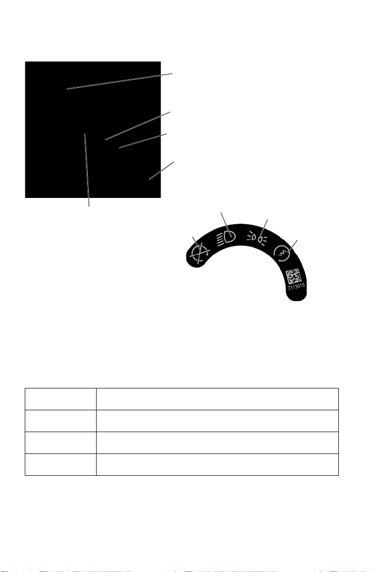
Ignition Switch/Light Switch
Use the ignition switch to start the engine and to turn the lights on or off.
The key can be removed from the switch when it is in the OFF position.
OFF Turn the key to the OFF position to stop the engine.
Electrical circuits are off.
HEADLIGHTS
ON
The low beam headlights are on. Electrical circuits are on.
Electrical equipment can be used.
POSITION
LIGHTS ON
The low beam headlights are off. Positon lights are on.
Electrical circuits are on. Electrical equipment can be used.
START Turn the key to the START position to engage the electric
starter. See page 56 for starting procedures.
AWD Switch
12V Accessory
Outlet
Ignition Switch/Light
Switch
Instrument
Cluster
Hazard
Switch
OFF
START
HEADLIGHTS
ON
POSITION
LIGHTS ON

33
FEATURES AND CONTROLS
Switches
All Wheel Drive (AWD) Switch (if equipped)
The AWD switch has three positions:
• All Wheel Drive (AWD)
• Differential Lock/Two Wheel
Drive (2WD)
• Off (1WD/Turf Mode)
Press the top of the rocker switch to
engage All Wheel Drive.
Move the switch to the center
position to lock the differential and
operate in two wheel drive (2WD).
Press the bottom of the switch to unlock the differential and allow the
rear drive wheels to operate independently (1WD). This mode of
operation is well suited to turf driving or when active traction is not
needed.
See page 71 for AWD/2WD/1WD operating instructions.
Auxiliary Outlet
The vehicle is equipped with a 12-volt accessory outlet on the dash. Use
the outlet to power an auxiliary light or other optional accessories or
lights. For service, the dash outlet connection is under the dash.
Hazard Switch
Push the hazard warning switch to cause all turn signal lights to flash
simultaneously. Use this feature to alert others of an emergency or other
situation requiring caution.
AWD
2WD
1WD/Turf
34
FEATURES AND CONTROLS
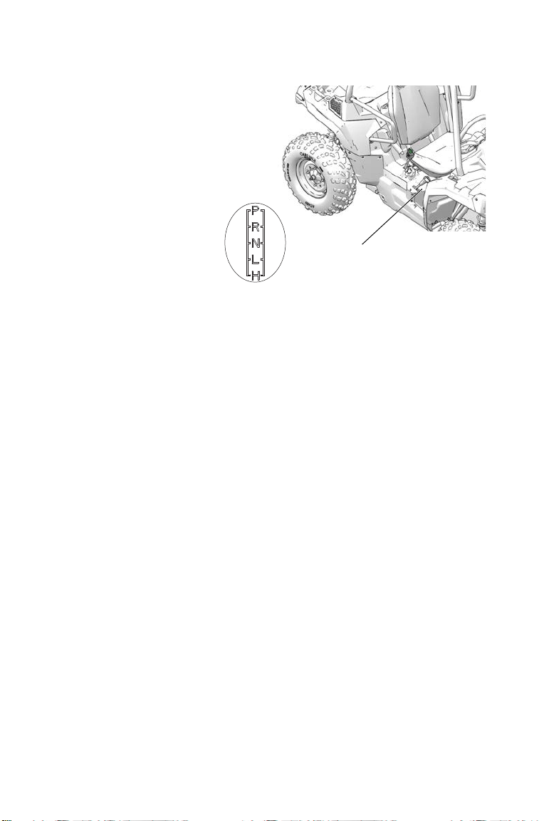
Gear Selector
To change gears, stop the
vehicle, and with the engine
idling, move the lever to the
desired gear. Do not attempt
to shift gears with engine
speed above idle or while
the vehicle is moving.
P: Park
R: Reverse
N: Neutral
L: Low Gear
H: High Gear
NOTICE: Do not attempt to shift the transmission while the vehicle is moving or
damage to the transmission could result. Always shift when the
vehicle is stationary and the engine is at idle.
Using Low Range
Always shift into low gear for any of the following conditions.
• Operating in rough terrain or over obstacles
• Loading the vehicle onto a trailer
• Towing heavy loads
Gear Selector

35
FEATURES AND CONTROLS
Brake Pedal
Depress the brake pedal to slow or
stop the vehicle. Apply the brakes
while starting the engine.
Throttle Pedal
Push the pedal down to increase
engine speed. Spring pressure returns
the pedal to the rest position when
released. Always check that the
throttle pedal returns normally before
starting the engine. Make sure there's
adequate throttle pedal freeplay. See
page 112 for throttle pedal adjustment
procedures.
This vehicle is equipped with a
throttle release switch, which is designed to reduce the risk of a frozen
or stuck throttle. If the throttle cable should stick in an open position
when the operator releases the throttle pedal, engine speed will be
limited, and power to the rear wheels will be reduced.
Throttle
Pedal
Brake
Pedal

36
FEATURES AND CONTROLS
Park Brake Lever
Always apply the service brakes before engaging or releasing the park
brake. To help prevent the vehicle from rolling, set the park brake when
parking the vehicle. When the park brake is set and the park brake
indicator is illuminated, engine speed is limited. If the accelerator is
applied, this limiting feature prevents operation, which protects the park
brake pads from excessive wear.
Tip: This feature will not operate properly if the park brake connector or switch
(under the hood) malfunctions or becomes disconnected, or if the switch
has moved. Check for disconnection, then see your dealer promptly if this
feature fails to operate properly.
1. To set the park brake, apply the
brakes.
2. Pull the park brake lever
upward as far as possible.
3. To release the park brake, apply
the brakes. Press the park brake
release inward and move the
lever downward as far as
possible.
Park Brake Lever
Park Brake Release
37
FEATURES AND CONTROLS
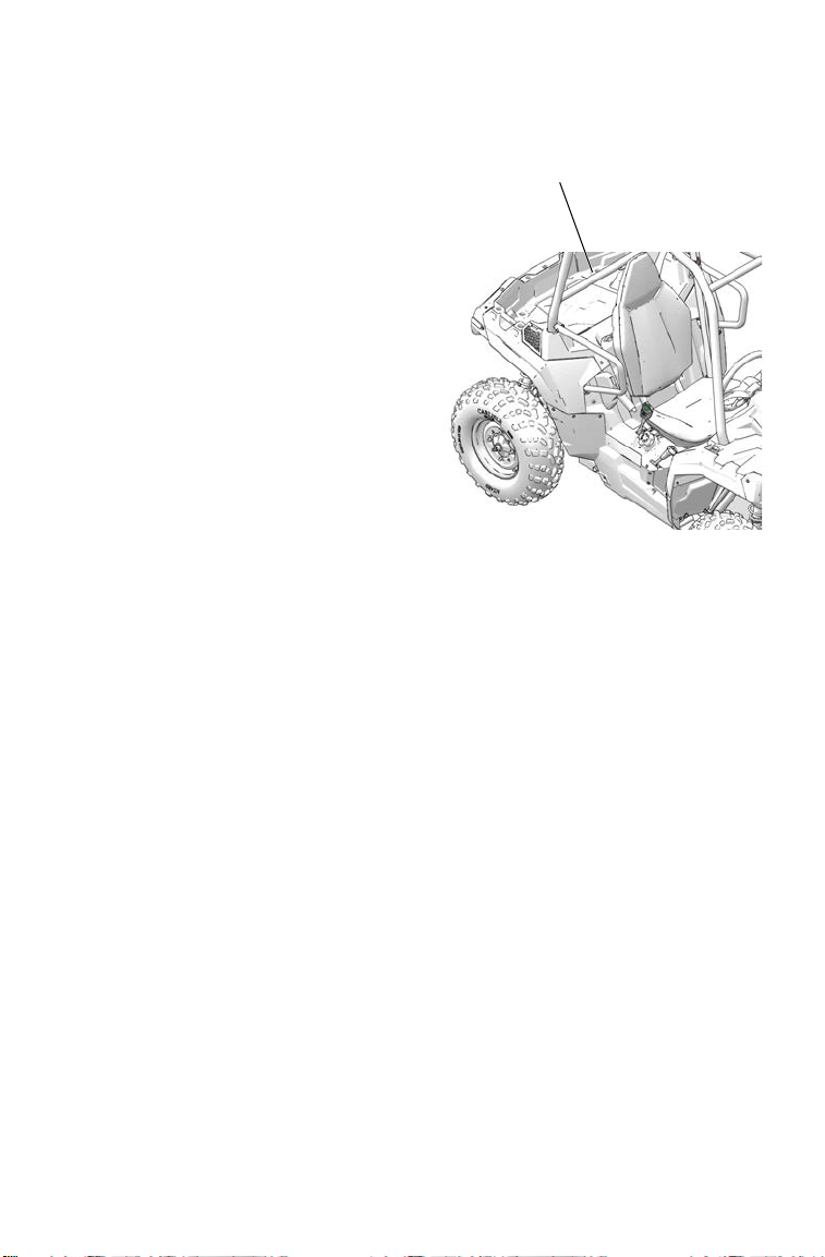
Rollover Protective Structure (ROPS)
The Rollover Protective Structure
(ROPS) on this vehicle meets
OSHA 1928.53 rollover
performance requirements.
Always have your authorized
POLARIS dealer thoroughly
inspect the ROPS if it ever
becomes damaged in any way.
No device can assure occupant
protection in the event of a
rollover. When used with seat
belts and cab nets, the ROPS
helps prevent occupants from
being ejected from the vehicle.
Always follow all safe operating
practices outlined in this manual
to avoid vehicle rollover.
WARNING! Vehicle rollover could cause severe injury or death. Always avoid
operating in a manner that could result in vehicle rollover.
ROPS Label
(on ROPS behind rear cab)

38
FEATURES AND CONTROLS
Instrument Cluster
High water pressure may damage
components. Wash the vehicle by
hand or with a garden hose using
mild soap. Do not use alcohol to
clean the instrument cluster. Do
not allow insect sprays to contact
the lens.
Speedometer
The speedometer displays vehicle
speed in either miles per hour
(MPH) or kilometers per hour
(km/h). See page 42.
Mode Button
Use the MODE button to toggle
through mode options. See page 42
for operation of the modes.
Rider Information
Center
Speedometer
Indicator
Lamps
MODE
Button
39
FEATURES AND CONTROLS
Instrument Cluster
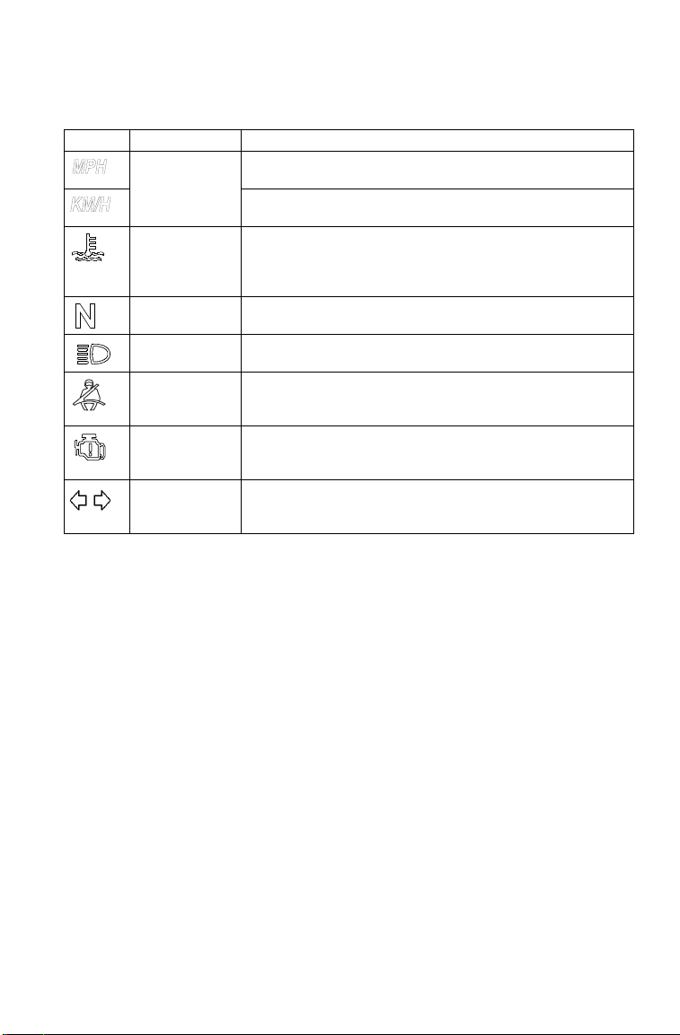
Indicator Lamps
Lamp Indicates Condition
Vehicle
Speed
When standard mode is selected, speed displays in
miles per hour.
When metric mode is selected, speed displays in
kilometers per hour.
Over
Temperature
This lamp illuminates to indicate an overheated
engine. If the indicator flashes, the overheating
condition remains, and the system will automatically
reduce engine power.
Neutral This lamp illuminates when the transmission is in
neutral and the ignition key is in the ON position.
High Beam (if
equipped)
This lamp illuminates when the headlamp switch is
set to high beam.
Helmet/Seat
Belt
This lamp flashes for several seconds when the key is
turned to the ON position. The lamp is a reminder to
wear helmet and seat belt before operating.
Check Engine This indicator appears if an EFI-related fault occurs.
Do not operate the vehicle if this warning appears.
Serious engine damage could result. See your dealer.
Direction
Indicators
A direction indicator flashes when a turn signal is
active. Both indicators flash when the hazard signal is
active.
40
FEATURES AND CONTROLS
Instrument Cluster
Rider Information Center
The rider information center is located in the instrument cluster. All
segments will light up for one second at start-up. If the instrument
cluster fails to illuminate, a battery over-voltage may have occurred and
the instrument cluster may have shut off to protect the electronic
speedometer. If this occurs, take the vehicle to your POLARIS dealer
for proper diagnosis.
The information center is set to display standard units of measurement
and a 12-hour clock at the factory. To change to metric and/or a 24-hour
clock, see page 43.
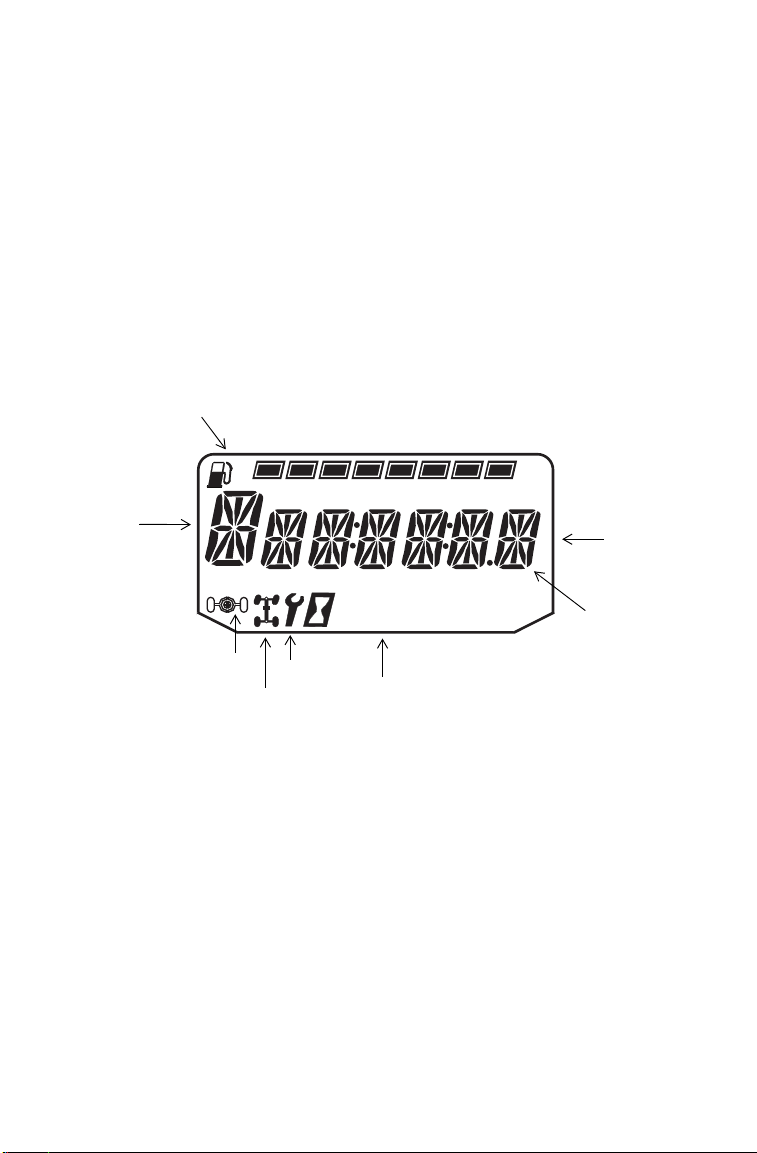
1. Gear Indicator - This indicator displays gear shifter position.
H = High Gear
L = Low Gear
N = Neutral
R = Reverse Gear
P = Park
-- = Gear Signal Error (or shifter between gears)
Trip 1
km
mi
RPM
FE
88
:
88
1
2
6
5
4
7
3
8

41
FEATURES AND CONTROLS
Instrument Cluster
Rider Information Center
2. Fuel Gauge - The segments of the fuel gauge show the level of fuel
in the fuel tank. When the last segment clears, a low fuel warning is
activated. All segments including the fuel icon will flash. Refuel
immediately.
Tip: If the fuel icon fails to display, an open or short circuit has occurred in the
fuel sensor circuit. See your POLARIS dealer.
3. Information Display Area - This area displays odometer, trip
meter, engine hour meter and programmable service hour interval.
4. Under / Over Voltage - This warning usually indicates that the
vehicle is operating at an RPM too low to keep the battery charged.
It may also occur when the engine is at idle and high electrical load
(lights, cooling fan, accessories) is applied. Drive at a higher RPM
or recharge the battery to clear the warning.
5. Clock - The clock displays time in a 12-hour or 24-hour format. See
page 43 for resetting instructions.
6. Service Indicator - A flashing wrench symbol alerts the operator
that the preset service interval has been reached. The vehicle should
be brought to your POLARIS dealer for scheduled maintenance.
See page 43 for resetting instructions.
7. 4X4 Indicator - This indicator illuminates when the 4X4 system is
engaged (switch is on 4X4).
8. Turf Mode Indicator (if equipped) - This indicator illuminates
when the operator unlocks the differential.

42
FEATURES AND CONTROLS
Instrument Cluster
Rider Information Center
Use the MODE button to toggle through the
information area options.
Display Units (Standard/Metric)
The display can be changed to show either
standard or metric units of measurement for
each of the following settings.
Tip: To exit the set-up mode, turn the key off. Wait 5 seconds, then turn the key
on. The gauge displays the mode that was displayed prior to setting the
units.
1. Turn the key to the OFF position.
2. Press and hold the MODE button while turning the key to the ON
position.
3. When the display flashes the distance setting, tap the MODE button
to advance to the desired setting.
4. Press and hold the MODE button to save the setting and advance to
the next display option.
5. Repeat the procedure to change remaining display settings.
Standard Display Metric Display
Distance Miles Kilometers
Fuel U.S. Gallons Liters, Imperial Gallons
Temperature Fahrenheit Celsius
Time 12-Hour Clock 24-Hour Clock
MODE
Button

43
FEATURES AND CONTROLS
Instrument Cluster
Rider Information Center
Clock Mode
Tip: The clock must be reset any time the battery has been disconnected or
discharged.
1. Turn the key to the ON position. Use the MODE button to toggle to
the odometer display.
2. Press and hold the MODE button until the hour segment flashes.
Release the button.
3. With the segment flashing, tap the MODE button to advance to the
desired setting.
4. Press and hold the MODE button until the next segment flashes.
Release the button.
5. Repeat steps 3-4 twice to set the 10-minute and 1-minute segments.
After completing the 1-minute segment, step 4 will save the new
settings and exit the clock mode.
6. Turn the key to the OFF position.
Odometer Mode
The odometer records and displays the distance traveled by the vehicle.
Trip Meter Mode
The trip meter records the distance traveled by the vehicle if reset before
each trip. To reset, select the trip meter mode. Press and hold the MODE
button until the meter resets to zero. In the Rider Information Center, the
trip meter display contains a decimal point, but the odometer displays
without a decimal point.
Hour Meter Mode
This mode logs the total hours the engine has been in operation.
Engine Temperature Mode
This mode displays current temperature of the coolant.
Tachometer Mode
The engine RPM is displayed digitally.
Tip: Small fluctuations in the RPM from day to day may be normal because of
changes in humidity, temperature and elevation.

44
FEATURES AND CONTROLS
Instrument Cluster
Rider Information Center
Programmable Service Interval
When the hours of engine operation equal the programmed service
interval setting, the wrench icon will flash for 5 seconds each time the
engine is started. When this feature is enabled, it provides a convenient
reminder to perform routine maintenance. The service interval is
programmed at 50 hours at the factory. Use the following procedure to
change the service interval.
1. Press the MODE button until remaining service hours display.
2. Press and hold the MODE button.
3. When the service hours flash, press and release the MODE button to
advance the hours to the desired setting (including OFF). Press and
hold the MODE button to set the new service hour interval.
Diagnostic Display Mode
The EFI diagnostic display mode is for informational purposes only.
Please see your POLARIS dealer for all major repairs.
The diagnostic mode is accessible only when the check engine warning
indicator activates after the key has been turned on. Leave the key on if
you want to view the active code (failure code).
The diagnostic mode becomes inaccessible if the key is turned off and
on and the warning indicator is no longer active. This allows the
determination of persistent as well as intermittent faults.
Inactive codes are stored in the history of the unit.
45
FEATURES AND CONTROLS
Instrument Cluster
Rider Information Center
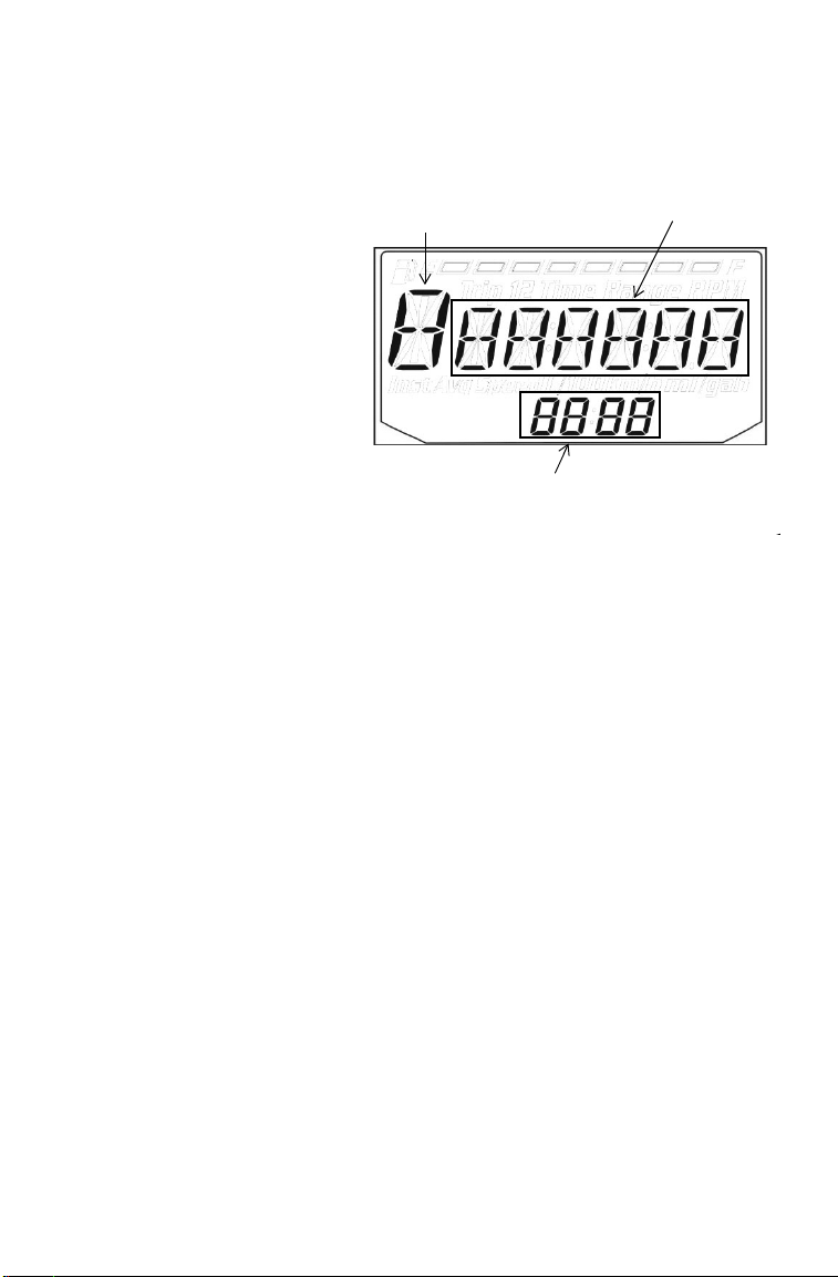
Engine Error Codes
The error screen displays
only when the CHECK
ENGINE light is on or
when it goes on and off
during one ignition cycle.
Error codes are not stored.
When the key is turned
OFF, the code and
message is lost, but will
reappear if the fault
reoccurs after restarting
the engine.
If the CHECK ENGINE
light illuminates, retrieve
the error codes from the
display.
1. If the error codes are not displayed, use the MODE button to toggle
until “Ck ENG” displays on the main line of the display.
2. Press and hold the MODE button to enter the diagnostics code
menu.
3. Record the three numbers displayed in the gear position, clock and
odometer displays.
4. Press the MODE button to advance to the next error code.
5. Press and hold the MODE button to exit the diagnostics code menu.
6. See pages 46-51 for code definitions and failure descriptions. Please
see your POLARIS dealer for all major repairs.
Suspect Parameter
Number (SPN)
Error Code
Number (0-9)
Failure Mode Indicator (FMI)

46
FEATURES AND CONTROLS
Instrument Cluster
Diagnostic Display Code Definitions
Open Load: There is a break in the wires that lead to the item listed in
the chart (injector, fuel pump, etc.), or the item has failed.
Short-to-Ground
: The wire is shorted to ground between the electronic
control unit and the item listed in the chart.
Shorted Load
: The wires leading to the item listed in the chart are
shorted together, or the item has shorted internally.
Short-to-Battery
: The wire leading from the item listed in the chart to
the electronic control unit is shorted to a wire at battery voltage.

47
FEATURES AND CONTROLS
Instrument Cluster
Diagnostic Display Code Definitions
Diagnostic Codes
Component Condition SPN FMI
Accelerator
Position 2
Data Erratic, Intermittent Or Incorrect 29 2
Voltage Above Normal, Or Shorted To High Source 29 3
Voltage Below Normal, Or Shorted To Low Source 29 4
Throttle Position
Sensor 1
Data Valid But Above Normal Operational Range - Most
Severe Level
51 0
Data Valid But Below Normal Operational Range - Most
Severe Level
51 1
Data Erratic, Intermittent Or Incorrect 51 2
Voltage Above Normal, Or Shorted To High Source 51 3
Voltage Below Normal, Or Shorted To Low Source 51 4
Abnormal Rate Of Change 51 10
Out Of Calibration 51 13
Vehicle Speed
Sensor
Data Valid But Above Normal Operational Range - Most
Severe Level
84 0
Data Valid But Below Normal Operational Range - Most
Severe Level
84 1
Data Erratic, Intermittent Or Incorrect 84 2
Voltage Above Normal, Or Shorted To High Source 84 3
Voltage Below Normal, Or Shorted To Low Source 84 4
Abnormal Frequency Or Pulse Width Or Period 84 8
Abnormal Update Rate 84 9
Abnormal Rate Of Change 84 10
Bad Intelligent Device Or Component 84 12
Received Network Data In Error 84 19
Accelerator
Position 1
Data Erratic, Intermittent Or Incorrect 91 2
Voltage Above Normal, Or Shorted To High Source 91 3
Voltage Below Normal, Or Shorted To Low Source 91 4
Manifold Absolute
Pressure Sensor
Data Erratic, Intermittent Or Incorrect 102 2
Voltage Above Normal, Or Shorted To High Source 102 3
Voltage Below Normal, Or Shorted To Low Source 102 4
Mechanical System Not Responding Or Out Of Adjustment 102 7
Abnormal Rate Of Change 102 10

48
FEATURES AND CONTROLS
Instrument Cluster
Diagnostic Display Code Definitions
Diagnostic Codes
Component Condition SPN FMI
Intake Air
Temperature Sensor
Data Erratic, Intermittent Or Incorrect 105 2
Voltage Above Normal, Or Shorted To High Source 105 3
Voltage Below Normal, Or Shorted To Low Source 105 4
Abnormal Rate Of Change 105 10
Data Valid But Above Normal Operating Range - Least
Severe Level
105 15
Engine Temperature
Sensor
Data Valid But Above Normal Operational Range - Most
Severe Level
110 0
Data Erratic, Intermittent Or Incorrect 110 2
Voltage Above Normal, Or Shorted To High Source 110 3
Voltage Below Normal, Or Shorted To Low Source 110 4
Abnormal Rate Of Change 110 10
Data Valid But Above Normal Operating Range - Least
Severe Level
110 15
Data Valid But Above Normal Operating Range - Moderately
Severe Level
110 16
Data Valid But Below Normal Operating Range - Least
Severe Level
110 17
System Power Data Valid But Above Normal Operational Range - Most
Severe Level
168 0
Data Valid But Below Normal Operational Range - Most
Severe Level
168 1
Voltage Above Normal, Or Shorted To High Source 168 3
Voltage Below Normal, Or Shorted To Low Source 168 4
Data Valid But Above Normal Operating Range - Moderately
Severe Level
168 16
Data Valid But Below Normal Operating Range - Moderately
Severe Level
168 18
Engine Speed Data Valid But Above Normal Operational Range - Most
Severe Level
190 0
Data Valid But Below Normal Operational Range - Most
Severe Level
190 1
Data Erratic, Intermittent Or Incorrect 190 2
Mechanical System Not Responding Or Out Of Adjustment 190 7
Received Network Data In Error 190 19
Condition Exists 190 31
Gear Sensor Signal Data Erratic, Intermittent Or Incorrect 523 2
Voltage Above Normal, Or Shorted To High Source 523 3
Voltage Below Normal, Or Shorted To Low Source 523 4
Abnormal Update Rate 523 9
ECU Memory Bad Intelligent Device Or Component 628 12
Out Of Calibration 628 13
Calibration Out Of Calibration 630 13
Crankshaft Position
Sensor
Data Erratic, Intermittent Or Incorrect 636 2
Abnormal Frequency Or Pulse Width Or Period 636 8
Injector 1 (Front)
(MAG) (SDI Port
Injector)
Voltage Above Normal, Or Shorted To High Source 651 3
Voltage Below Normal, Or Shorted To Low Source 651 4
Current Below Normal Or Open Circuit 651 5

49
FEATURES AND CONTROLS
Instrument Cluster
Diagnostic Display Code Definitions
Diagnostic Codes
Component Condition SPN FMI
Fan Relay Driver
Circuit
Voltage Above Normal, Or Shorted To High Source 1071 3
Voltage Below Normal, Or Shorted To Low Source 1071 4
Current Below Normal Or Open Circuit 1071 5
Ignition Coil Primary
Driver 1 (Front)
(MAG)
Voltage Above Normal, Or Shorted To High Source 1268 3
Voltage Below Normal, Or Shorted To Low Source 1268 4
Current Below Normal Or Open Circuit 1268 5
Fuel Pump Driver
Circuit
Voltage Above Normal, Or Shorted To High Source 1347 3
Voltage Below Normal, Or Shorted To Low Source 1347 4
Current Below Normal Or Open Circuit 1347 5
Oxygen Sensor 1 Data Erratic, Intermittent Or Incorrect 3056 2
Voltage Above Normal, Or Shorted To High Source 3056 3
Voltage Below Normal, Or Shorted To Low Source 3056 4
Bad Intelligent Device Or Component 3056 12
ECU Output Supply
Voltage 1
Data Valid But Above Normal Operational Range - Most
Severe Level
3597 0
Data Valid But Below Normal Operational Range - Most
Severe Level
3597 1
Voltage Above Normal, Or Shorted To High Source 3597 3
Voltage Below Normal, Or Shorted To Low Source 3597 4
Data Valid But Above Normal Operating Range - Moderately
Severe Level
3597 16
Data Valid But Below Normal Operating Range - Moderately
Severe Level
3597 18
ECU Output Supply
Voltage 2
Data Valid But Above Normal Operational Range - Most
Severe Level
3598 0
Data Valid But Below Normal Operational Range - Most
Severe Level
3598 1
Voltage Above Normal, Or Shorted To High Source 3598 3
Voltage Below Normal, Or Shorted To Low Source 3598 4
Data Valid But Above Normal Operating Range - Moderately
Severe Level
3598 16
Data Valid But Below Normal Operating Range - Moderately
Severe Level
3598 18
ECU Output Supply
Voltage 3
Data Valid But Above Normal Operational Range - Most
Severe Level
3599 0
Data Valid But Below Normal Operational Range - Most
Severe Level
3599 1
Voltage Above Normal, Or Shorted To High Source 3599 3
Voltage Below Normal, Or Shorted To Low Source 3599 4
Data Valid But Above Normal Operating Range - Moderately
Severe Level
3599 16
Data Valid But Below Normal Operating Range - Moderately
Severe Level
3599 18
ETC Accelerator
Position Sensor
Outputs 1 & 2
Correlation
Data Erratic, Intermittent Or Incorrect 65613 2

50
FEATURES AND CONTROLS
Instrument Cluster
Diagnostic Display Code Definitions
Diagnostic Codes
Component Condition SPN FMI
Throttle Position Sensor 2 Data Valid But Above Normal Operational Range -
Most Severe Level
520198 0
Data Valid But Below Normal Operational Range -
Most Severe Level
520198 1
Data Erratic, Intermittent Or Incorrect 520198 2
Voltage Above Normal, Or Shorted To High Source 520198 3
Voltage Below Normal, Or Shorted To Low Source 520198 4
Abnormal Rate Of Change 520198 10
Out Of Calibration 520198 13
Active Descent Control
System
Voltage Above Normal, Or Shorted To High Source 520203 3
Voltage Below Normal, Or Shorted To Low Source 520203 4
Current Below Normal Or Open Circuit 520203 5
Fuel Correction Front Data Valid But Above Normal Operating Range -
Least Severe Level
520204 15
Data Valid But Below Normal Operating Range -
Least Severe Level
520204 17
All Wheel Drive Control
Circuit
Voltage Above Normal, Or Shorted To High Source 520207 3
Voltage Below Normal, Or Shorted To Low Source 520207 4
Current Below Normal Or Open Circuit 520207 5
Oxygen Sensor Heater 1 Data Erratic, Intermittent Or Incorrect 520209 2
Voltage Above Normal, Or Shorted To High Source 520209 3
Voltage Below Normal, Or Shorted To Low Source 520209 4
Current Below Normal Or Open Circuit 520209 5
Accelerator Position/Brake
Position Interaction
Condition Exists 520275 31
Throttle Position Sensor (1
or 2 Indeterminable)
Data Erratic, Intermittent Or Incorrect 520276 2
Bad Intelligent Device Or Component 520276 12
Throttle Body Control -
Power Stage
Data Erratic, Intermittent Or Incorrect 520277 2
Voltage Above Normal, Or Shorted To High Source 520277 3
Voltage Below Normal, Or Shorted To Low Source 520277 4
Abnormal Frequency Or Pulse Width Or Period 520277 8
Condition Exists 520277 31
Throttle Body Control -
Return Spring Check Failed
Condition Exists 520278 31
Throttle Body Control -
Adaption Aborted
Condition Exists 520279 31
Throttle Body Control -
Limp Home Position Check
Failed
Condition Exists 520280 31
Throttle Body Control -
Mechanical Stop
Adaptation Failure
Condition Exists 520281 31
Throttle Body Control -
Repeated Adaptation
Failed
Condition Exists 520282 31
Throttle Body Control Data Erratic, Intermittent Or Incorrect 520283 2
Voltage Above Normal, Or Shorted To High Source 520283 3
Voltage Below Normal, Or Shorted To Low Source 520283 4

51
FEATURES AND CONTROLS
Instrument Cluster
Diagnostic Display Code Definitions
Diagnostic Codes
Component Condition SPN FMI
Throttle Body Control - Position Deviation
Fault
Condition Exists 520284 31
ECU Monitoring Error Condition Exists 520286 31
ECU Monitoring Error (Level 3) Condition Exists 520287 31
ECU Monitoring of Injection Cut Off
(Level 1)
Condition Exists 520288 31
ECU Monitoring of Injection Cut Off
(Level 2)
Condition Exists 520289 31
Throttle Body Control - Requested
Throttle Angle Not Plausible
Condition Exists 520305 31
ECU ADC Fault - No Load Condition Exists 520306 31
ECU ADC Fault - Voltage Condition Exists 520307 31
Accelerator Sensor Sync Fault - Sensor
Diff Exceeds Limit
Condition Exists 520308 31
ECU Fault - ICO Condition Exists 520309 31
ECU Fault - Hardware Disruption Condition Exists 520311 31
Idle Fuel Correction Bank 1 Data Valid But Above Normal
Operating Range - Least Severe
520342 15
Data Valid But Below Normal
Operating Range - Least Severe
520342 17
Adaptive Fuel Correction Bank 1 Data Valid But Above Normal
Operating Range - Least Severe
520344 15
Data Valid But Below Normal
Operating Range - Least Severe
520344 17

52
OPERATION
Failure to operate the vehicle properly can result in a collision, loss of control,
accident or rollover, which may result in serious injury or death. Read and
understand all safety warnings outlined in the safety section of this owner’s
manual.
Vehicle Break-in Period
The break-in period for your new POLARIS vehicle is the first 25 hours
of operation, or the time it takes to use the first two tanks full of
gasoline. No single action on your part is as important as a proper break-
in period. Careful treatment of a new engine and drive components will
result in more efficient performance and longer life for these
components. Perform the following procedures carefully.
NOTICE: Excessive heat build-up during the first three hours of operation will
damage close-fitted engine parts and drive components. Do not
operate at full throttle or high speeds during the first three hours of
use.
Use of any oils other than those recommended by POLARIS may
cause serious engine damage. We recommend the use of POLARIS
PS-4 Full Synthetic 5W-50 4-Cycle Oil for your 4-cycle engine.
WARNING

53
OPERATION
Vehicle Break-in Period
Engine and Drivetrain Break-in
1. Fill the fuel tank with gasoline. See page 29. Always exercise
extreme caution whenever handling gasoline.
2. Check the oil level. See page 92. Add the recommended oil as
needed to maintain the oil level in the safe operating range.
3. Complete the New Operator Driving Procedures outlined on pages
58-59.
4. Avoid aggressive use of the brakes.
5. Vary throttle positions. Do not operate at sustained idle.
6. Pull only light loads.
7. Perform regular checks on fluid levels, controls and areas outlined
on the daily pre-ride inspection checklist. See page 54.
8. During the break-in period, change both the oil and the filter at 25
hours or one month.
9. Check fluid levels of transmission and all gearcases after the first 25
hours of operation and every 100 hours thereafter.
Brake System Break-in
Apply only moderate braking force for the first 50 stops. Aggressive or
overly forceful braking when the brake system is new could damage
brake pads and rotors.
PVT Break-in (Clutches/Belt)
A proper break-in of the clutches and drive belt will ensure a longer life
and better performance. Break in the clutches and belt by operating at
slower speeds during the break-in period as recommended. Pull only
light loads. Avoid aggressive acceleration and high speed operation
during the break-in period.
If a belt fails, always clean any debris from the PVT intake and outlet
duct and from the clutch and engine compartments when replacing the
belt.

54
OPERATION
Pre-Ride Inspection
Failure to inspect and verify that the vehicle is in safe operating
condition before operating increases the risk of an accident. Always
inspect the vehicle before each use to make sure it's in safe operating
condition.
Item Remarks Page
Brake system/pedal travel Ensure proper operation 35, 111
Brake fluid Ensure proper level 112
Front suspension Inspect, lubricate if necessary 89
Rear suspension Inspect, lubricate if necessary 89
Steering/Steering Lock Unlock the steering; Ensure free
operation
114
Tires Inspect condition and pressure 13, 115
Wheels/fasteners Inspect, ensure fastener tightness 115
Frame nuts, bolts,
fasteners
Inspect, ensure tightness -
Fuel and oil Ensure proper levels 41, 92
Coolant level Ensure proper level 103-104
Coolant hoses Inspect for leaks -
Throttle Ensure proper operation 111
Indicator lights/switches Ensure proper operation 31
Air filter, pre-filter Inspect, clean 108-109
Intake pre-filters Inspect, clean 109
Headlamps Check operation, apply POLARIS
dielectric grease when lamp is
replaced
117
Turn Signals Ensure operation of all signal lamps 31
Mirrors Adjust for best side/rear vision 27
Horn Ensure operation 31
Brake light/tail lamps Check operation, apply POLARIS
dielectric grease when lamp is
replaced
117
Riding gear Wear approved helmet, goggles,
and protective clothing
10
Seat Latch Push down on the seat back to
ensure the latch is secure
29
Seat Belt Check length of belt for damage,
check latches for proper operation
30
Cab Nets Check for wear or damage, ensure
proper installation
28

55
OPERATION
Safe Operation Practices
1. POLARIS strongly encourages you and any family members who
will be riding this vehicle to take a training course.
2. Do not allow anyone under 16 years of age or without a valid
driver’s license to operate this vehicle.
3. Never carry a passenger on this vehicle.
4. Engine exhaust fumes are poisonous. Never start the engine or let it
run in an enclosed area.
5. Never operate with accessories not approved by POLARIS for use
on this vehicle.
6. Use caution and drive at reduced speeds in conditions of reduced
visibility such as fog, rain and darkness. Clean headlights
frequently and replace burned out headlamps promptly.
7. Always operate at a speed that's appropriate for the terrain, the
visibility and operating conditions and your skills and experience.
Never operate at excessive speeds. Never attempt wheelies, jumps,
or other stunts. Keep both hands on the steering wheel during
operation.
8. Never consume alcohol or drugs before or while operating this
vehicle.
9. Always use the size and type of tires specified for your vehicle.
Always maintain proper tire pressure.
10. Never operate a damaged vehicle. After any rollover or accident,
have a qualified service dealer inspect the entire machine for
possible damage.
11. Never operate the vehicle on a frozen body of water unless you have
first verified that the ice is sufficiently thick to support the weight
and moving force of the vehicle, you and your cargo, together with
any other vehicles in your party.
12. Do not touch hot exhaust system components. Always keep
combustible materials away from the exhaust system.
13. Always remove the ignition key when the vehicle is not in use to
prevent unauthorized use.

56
OPERATION
Starting the Engine
WARNING! Always unlock the steering before starting the engine.
1. Position the vehicle on a level surface outdoors or in a well-
ventilated area.
2. Sit in the driver's seat and fasten the seat belt. Secure the cab nets.
3. Place the transmission in PARK.
4. Apply the brakes. Do not
press the throttle pedal
while starting the engine.
5. Turn the ignition key to the
START position. Engage
the starter for a maximum
of five seconds. Release
the key when the engine
starts. Turn the key to
either HEADLIGHTS ON
or POSITION LIGHTS
ON.
6. If the engine does not start within five seconds, return the ignition
switch to the OFF position and wait five seconds. Repeat steps 5
and 6 until the engine starts.
7. Vary the engine RPM slightly with the throttle to aid in warm up
until the engine idles smoothly.
NOTICE: Operating the vehicle immediately after starting could cause engine
damage. Allow the engine to warm up for several minutes before
operating the vehicle.
Cold Weather Operation
If the vehicle is used year-round, check the oil level frequently. A rising
oil level could indicate the accumulation of contaminates such as water
or excess fuel in the bottom of the crankcase. Water in the bottom of the
crankcase can lead to engine damage and must be drained. Water
accumulation increases as outside temperature decreases.
OFF
START
HEADLIGHTS
ON
POSITION
LIGHTS ON

57
OPERATION
Stopping the Engine
1. Release the throttle pedal completely and brake to a complete stop.
2. Place the transmission in PARK.
3. Turn the engine off.
Braking
1. Release the throttle pedal completely. (When the throttle pedal is
released completely and engine speed slows to near idle, the vehicle
has no engine braking.)
2. Press on the brake pedal evenly and firmly. Practice starting and
stopping (using the brakes) until you're familiar with the controls.
Parking the Vehicle
1. Stop the vehicle on a level surface. When parking inside a garage or
other structure, be sure that the structure is well ventilated and that
the vehicle is not close to any source of flame or sparks, including
any appliance with pilot lights.
2. Place the transmission in PARK.
3. Turn the engine off.
4. Remove the ignition key to prevent unauthorized use.

58
OPERATION
New Operator Driving Procedures
1. Read and understand the owner's manual and all warning and
instruction labels before operating this vehicle.
2. Take a training course.
3. Perform the pre-ride inspection. See page 54.
4. Do not tow or carry cargo during this period.
5. Select an open area that allows room to familiarize yourself with
vehicle operation and handling.
6. The driver must wear helmet, eye protection, gloves, long-sleeve
shirt, long pants, over-the-ankle boots and seat belt at all times.
7. Sit in the driver's seat and fasten the seat belt.
8. Make sure all cab nets are properly secured.
9. Place the transmission in PARK.
10. Start the engine.

59
OPERATION
New Operator Driving Procedures
11. Apply the brakes and shift into low gear.
12. Check your surroundings and determine your path of travel.
13. Keeping both hands on the steering wheel, slowly release the brakes
and depress the throttle with your right foot to begin driving.
14. Drive slowly at first. On level surfaces, practice starting, stopping,
turning, maneuvering, using the throttle and brakes and driving in
reverse. Learn how the vehicle handles when making both left and
right turns at a slow speed.
WARNING! Operating in TURF mode (if equipped) when on sloped, uneven, or
loose terrain could cause loss of control and result in serious injury or death.
One rear wheel may slip and lose traction or may lift up and grab when it
touches the ground again.
15. Increase speed only after mastering all maneuvers at a slow speed.
16. After you become skilled at making turns and begin to operate at
faster speeds, follow these precautions:
• Avoid sharp turns.
• Never turn while applying heavy throttle.
• Never make abrupt steering maneuvers.
• Operate at speeds appropriate for your skills, the conditions and
the terrain.
• DO NOT do power slides, “donuts”, jumps or other driving
stunts.
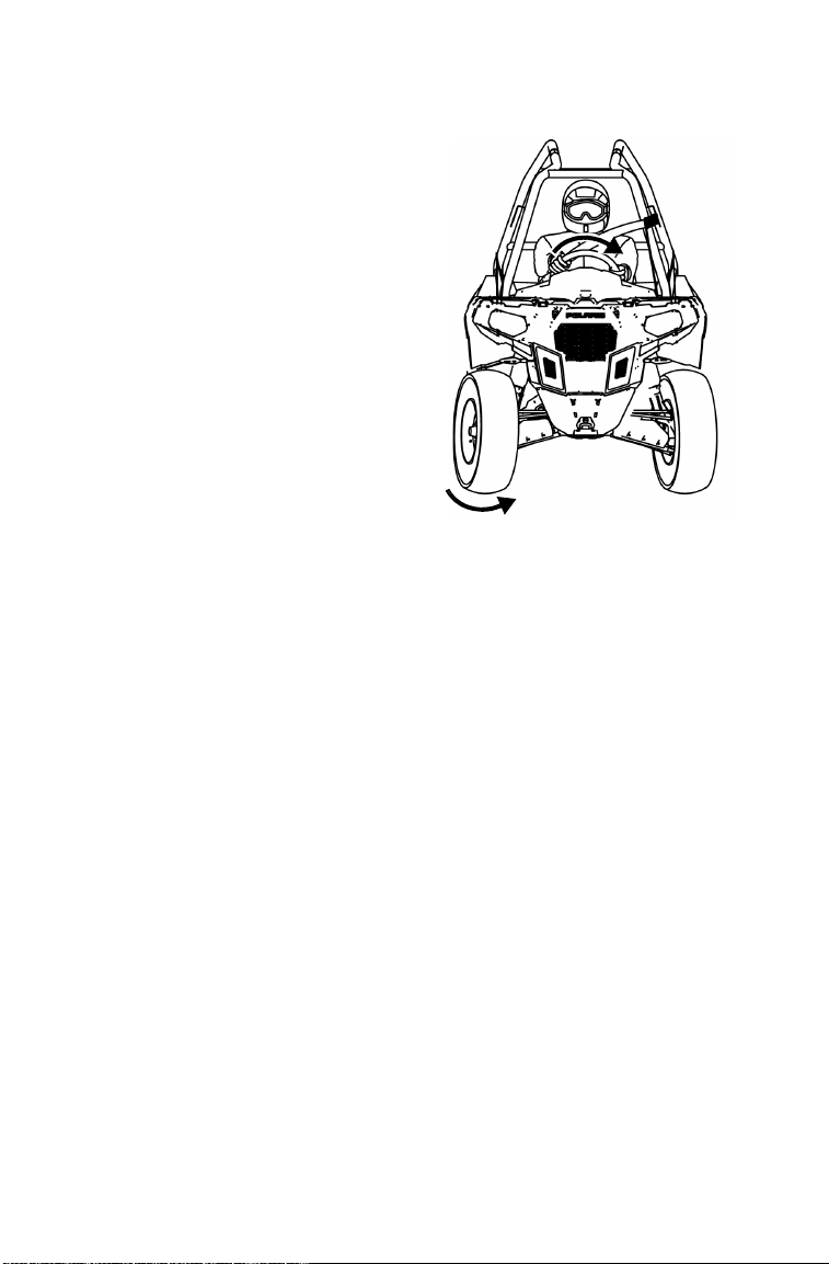
60
OPERATION
Turning the Vehicle
Your vehicle is equipped with a
solid rear axle, which drives both
rear wheels equally at all times.
This means that the wheel on the
outside of the turn must travel a
greater distance than the inside
wheel when turning and the inside
tire must slip traction slightly.
To turn the vehicle, rotate the
steering wheel in the direction of
the turn.
Practice making turns at slow
speeds before attempting to turn at
faster speeds.
WARNING! Turning improperly can
result in vehicle rollover. Never turn
abruptly or at sharp angles. Never turn
at high speeds.
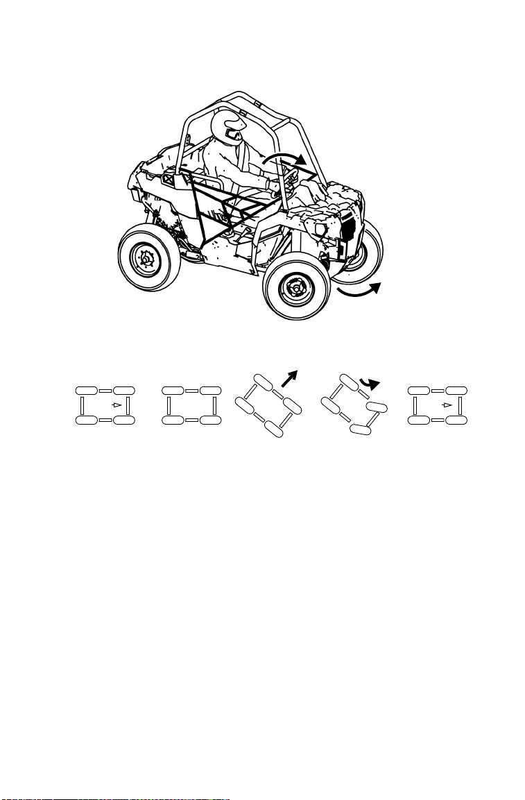
61
OPERATION
Driving on Slippery Surfaces
When driving on slippery surfaces such as wet trails, loose gravel, or
ice, be alert for the possibility of skidding and sliding. Follow these
precautions when encountering slippery conditions:
1. Do not operate on excessively rough, slippery or loose terrain.
2. Slow down before entering slippery areas.
3. Maintain a high level of alertness, reading the trail and avoiding
quick, sharp turns, which can cause skids.
4. Engage all-wheel drive before wheels begin to lose traction.
NOTICE: Severe damage to the drive train may occur if the AWD is engaged
while the wheels are spinning. Always allow the wheels to stop
spinning before engaging AWD.
5. Correct a skid by turning the steering wheel in the direction of the
skid. Never apply the brakes during a skid.
Sideways
skid
Turn in
direction of
skid
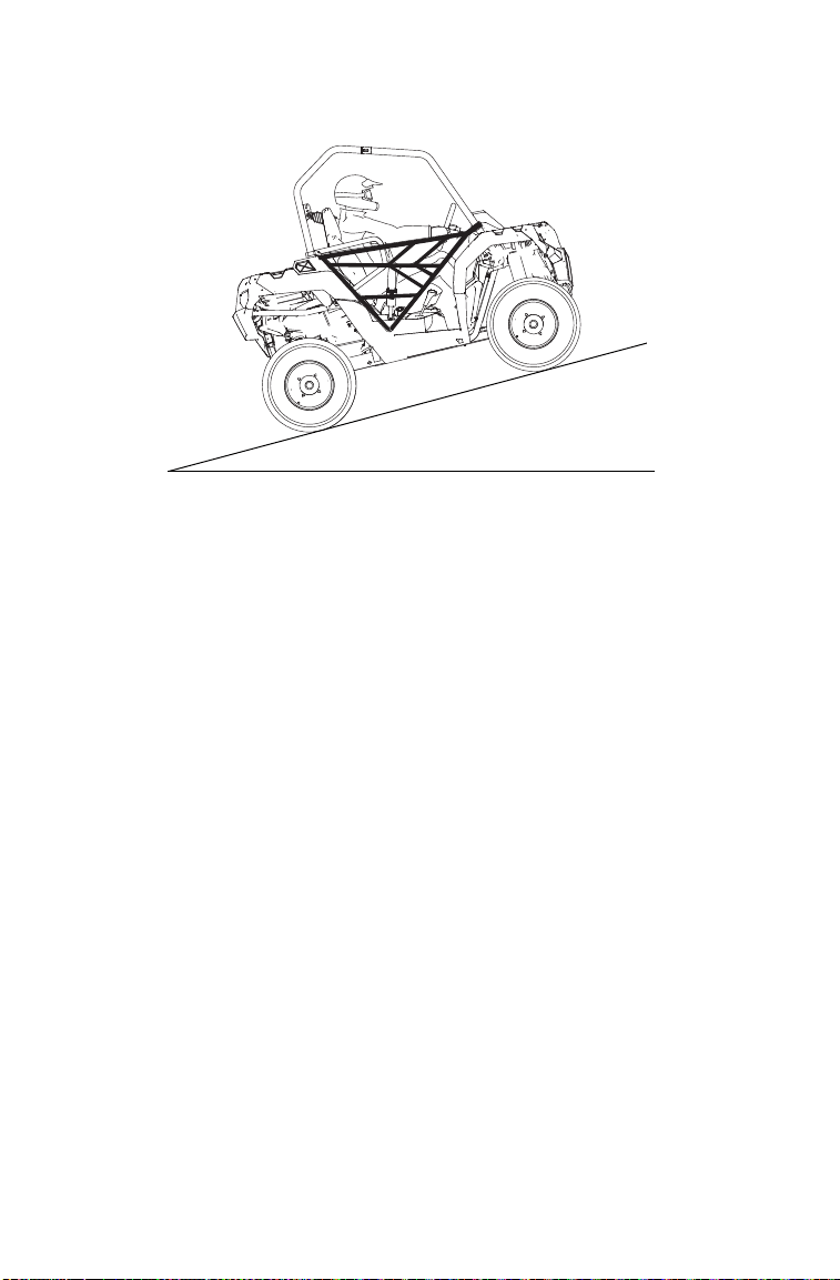
62
OPERATION
Driving Uphill
Whenever traveling uphill, follow these precautions:
1. Always check the terrain carefully before ascending any hill. Never
drive on hills with excessively slippery or loose surfaces.
2. Never operate in TURF mode (if equipped) while operating on a hill
or other irregular terrain. Always move the AWD switch to AWD
before ascending or descending a hill.
3. Avoid excessively steep hills. If ascending a steeper grade is
unavoidable, engage all-wheel drive before ascending.
4. Drive straight uphill.
5. Proceed at a steady rate of speed and throttle opening. Never open
the throttle suddenly.
6. Avoid unnecessary changes in speed or direction.
7. Never go over the crest of a hill at high speed. An obstacle, a sharp
drop, or another vehicle or person could be on the other side of the
hill.
8. If the vehicle stalls while climbing a hill, apply the brakes. Place the
transmission in reverse and slowly allow the vehicle to roll straight
downhill while applying light brake pressure to control speed.

63
OPERATION
Driving on a Sidehill (Sidehilling)
Driving on a sidehill is not recommended. Improper procedure could
cause loss of control or rollover. Avoid crossing the side of any hill
unless absolutely necessary.
If crossing a hill is unavoidable, follow these precautions:
1. Engage all-wheel drive.
2. Never operate in TURF mode (if equipped) while operating on a hill
or other irregular terrain. Always move the AWD switch to AWD
before ascending or descending a hill.
3. Drive slowly and use extreme caution.
4. If the vehicle begins to overturn, or if it feels as if it may overturn,
immediately turn downhill.
5. Avoid obstacles and changes in terrain that may lower or raise one
side of the vehicle or cause the vehicle to slide.
6. If the vehicle begins to slide downhill, immediately turn downhill to
stop the slide, or stop the vehicle and maneuver slowly and
carefully until the vehicle can be driven straight downhill.
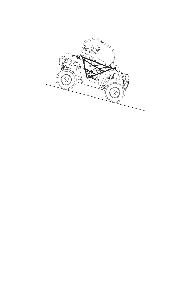
64
OPERATION
Driving Downhill
Whenever descending a hill, follow these precautions:
1. Avoid excessively steep hills.
2. Never operate in TURF mode (if equipped) while operating on a hill
or other irregular terrain. Always move the AWD switch to AWD
before ascending or descending a hill.
3. Slow down. Never travel down a hill at high speed.
4. Always check the terrain carefully before descending a hill. Never
drive on hills with excessively slippery or loose surfaces.
5. Always descend a hill with the transmission in forward gear. Never
descend a hill with the transmission in neutral.
6. Avoid traveling down a hill at an angle, which would cause the
vehicle to lean sharply to one side. Travel straight downhill.
7. Apply the brakes lightly to aid in slowing.
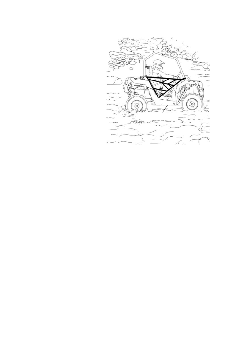
65
OPERATION
Driving Through Water
Your vehicle can operate
through water with a
maximum recommended depth
equal to floor level. Follow
these precautions when
operating through water:
1. Determine water depth and
current before entering
water.
2. Choose a crossing where
the water level is lowest
and where both banks
have gradual inclines.
Never operate in water that
exceeds the maximum
recommended depth.
WARNING! The large tires on your vehicle may cause the vehicle to float in
deep or fast-flowing water, which could result in loss of traction, loss of control,
rollover or accident.
3. Wet brakes may have reduced stopping ability. After leaving water,
test the brakes. Apply them lightly several times while driving
slowly. The friction will help dry out the pads.
NOTICE: Major engine damage can result if the vehicle is not thoroughly
inspected after operation in water. Perform the services outlined in
the maintenance chart. See page 85. Give special attention to engine
oil, transmission oil, demand drive fluid, rear gearcase oil (if
equipped) and all grease fittings.
If your vehicle becomes immersed or is operated in water that
exceeds the floor level, take it to your POLARIS dealer for service
before starting the engine. If it's impossible to bring the vehicle to
your dealer before starting the engine, perform the service outlined
on page 120, and take the vehicle to your dealer at the first
opportunity.
Floor Level
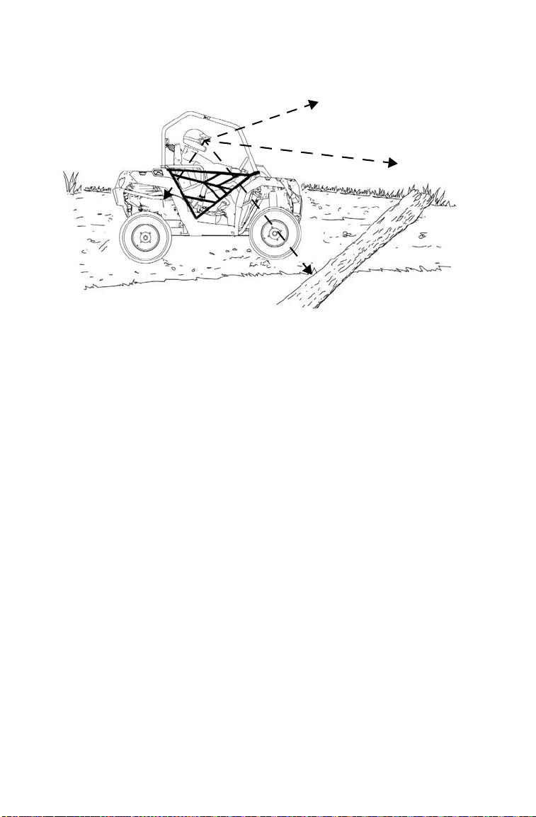
66
OPERATION
Driving Over Obstacles
Follow these precautions when operating over obstacles:
1. Always check for obstacles before operating in a new area.
2. Look ahead and learn to read the terrain. Be constantly alert for
hazards such as logs, rocks and low hanging branches.
3. Travel slowly and use extra caution when operating on unfamiliar
terrain. Not all obstacles are immediately visible.
4. Avoid operating over large obstacles such as large rocks and fallen
trees. If unavoidable, use extreme caution and operate slowly.
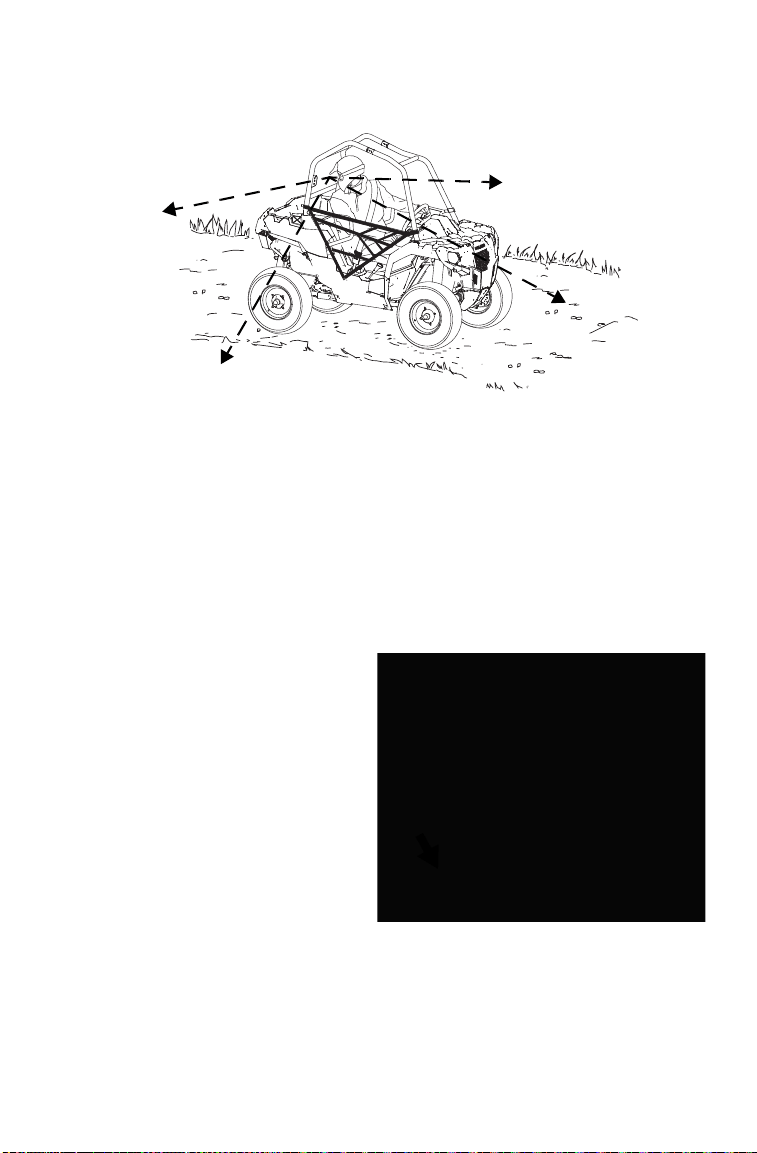
67
OPERATION
Driving in Reverse
Follow these precautions when operating in reverse:
1. Always check for obstacles or people behind the vehicle.
2. Apply the throttle lightly. Never apply throttle suddenly.
3. Back slowly.
4. Apply the brakes lightly for stopping.
5. Avoid making sharp turns.
Parking on an Incline
A rolling vehicle can result in
serious injury. Avoid parking on
an incline. If parking on an
incline is unavoidable, follow
these precautions:
1. Place the transmission in
PARK.
2. Turn the engine off.
3. Block the rear wheels on the
downhill side, or park the
vehicle in a sidehill position
instead.

68
OPERATION
Hauling Cargo
Overloading the vehicle or carrying or towing cargo improperly can alter vehicle
handling and may cause loss of control or brake instability. Always follow these
precautions when hauling cargo:
Never exceed the stated load capacity for this vehicle.
REDUCE SPEED AND ALLOW GREATER DISTANCES FOR BRAKING
WHEN HAULING CARGO.
NEVER EXCEED THE MAXIMUM WEIGHT CAPACITY of the vehicle. When
determining the weight you are adding to the vehicle, include the weight of the
operator, accessories, loads in the rack or box and the load on the trailer tongue.
The combined weight of these items must not exceed the maximum weight
capacity.
Always load the cargo box with the load as far forward and as low as possible.
When operating over rough or hilly terrain, reduce speed and cargo to maintain
stable driving conditions.
Always operate the vehicle with extreme care when hauling or towing loads.
Slow down and drive in the lowest gear available.
SECURE ALL LOADS BEFORE OPERATING. Unsecured loads can create
unstable operating conditions, which could result in loss of control of the vehicle.
OPERATE ONLY WITH STABLE AND SAFELY ARRANGED LOADS. When
handling off-centered loads that cannot be centered, securely fasten the load
and operate with extra caution. Always attach the tow load to the hitch point
designated for your vehicle.
HEAVY LOADS CAN CAUSE BRAKING AND CONTROL PROBLEMS. Use
extreme caution when applying brakes with a loaded vehicle. Avoid terrain or
situations that may require backing downhill.
USE EXTREME CAUTION when operating with loads that extend over the rack
sides. Stability and maneuverability may be adversely affected, causing vehicle
rollover.
DO NOT TRAVEL FASTER THAN THE RECOMMENDED SPEEDS. Vehicle
should never exceed 10 MPH (16 km/h) while towing a load on a level grass
surface. Vehicle speed should never exceed 5 MPH (8 km/h) when towing loads
in rough terrain, while cornering, or while ascending or descending a hill.
Carrying a passenger in the cargo box could
result in a fall from the vehicle or contact with
moving components. Never allow a passenger
to ride in the cargo box.
WARNING

69
OPERATION
Hauling Cargo
Your POLARIS vehicle has been designed to carry or tow specific
capacities. Reduce speed and allow a greater distance for braking when
carrying cargo.
Loads should be centered and carried as low as possible in the box. For
stability on rough or hilly terrain, reduce both speed and cargo. Exercise
caution if the cargo load extends over the side of the box.
Always read and understand the load distribution warnings listed on
warning labels and in this manual. Never exceed the maximum
capacities specified for your vehicle. See page 132.
Belt Life
To extend belt life, use low gear when hauling or towing heavy cargo.

70
OPERATION
Towing Loads
Towing is approved OFF-ROAD ONLY. See your POLARIS dealer about
configuring the vehicle to be certified to tow a trailer on-road.
Towing improperly can alter vehicle handling and may cause loss of control or
brake instability.
Always follow these precautions when towing:
1. Never load more than 150 lbs. (68 kg) tongue weight on the towing
bracket.
2. When towing a disabled vehicle, place the disabled vehicle’s
transmission in neutral. Do not operate the vehicle faster than 10
MPH (16 km/h) when towing.
3. Towing a trailer increases braking distance. Do not operate the
vehicle faster than 10 MPH (16 km/h) when towing.
4. Do not tow more than the recommended weight for the vehicle.
5. Attach a trailer to the trailer hitch bracket only. Do not attach a
trailer to any other location, which could result in loss of control of
the vehicle.
6. The total load (operator, accessories, cargo and weight on hitch)
must not exceed the maximum weight capacity of the vehicle.
Total Towed
Load Weight
(Level Ground)
Total Towed
Load Weight
(15° grade)
Total Hitch
Vertical
Weight
Maximum
Towing
Speed
1500 lbs. (680 kg) 850 lbs. (386 kg) 150 lbs. (68 kg) 10 MPH (16 km/h)
WARNING
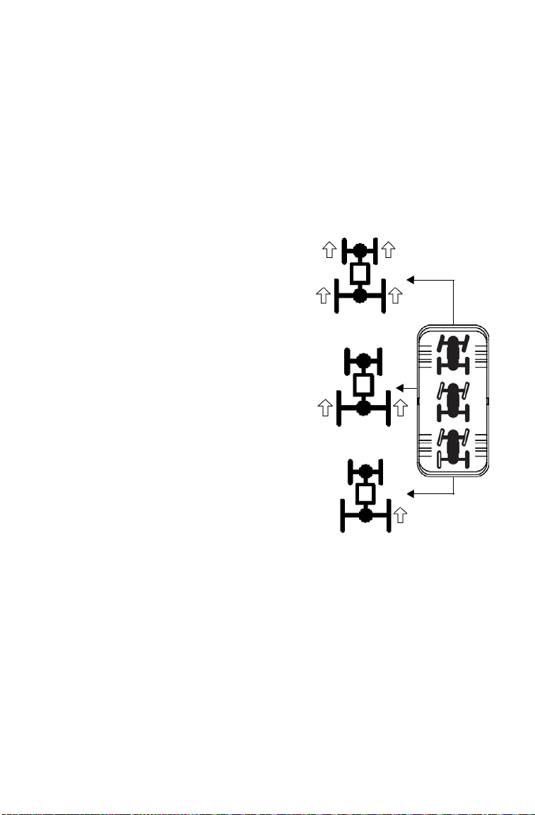
71
OPERATION
All Wheel Drive (AWD) System
Engaging AWD
Press the top of the rocker switch to engage All Wheel Drive (AWD).
Once enabled, the AWD remains enabled until the switch is turned off.
The AWD switch may be turned on or off while the vehicle is moving.
When the AWD switch is on, the front gearcase will automatically
engage any time the rear wheels lose traction. When the rear wheels
regain traction, the front gearcase will automatically disengage.
Tip: AWD will not engage initially until speed is less than 5 MPH (8 km/h).
Engage the AWD before getting
into conditions where front wheel
drive may be needed. If the rear
wheels are spinning, release the
accelerator before switching to
AWD.
NOTICE: Switching to AWD while
the rear wheels are
spinning may cause
severe drive train
damage. Always switch to
AWD while the rear
wheels have traction or
are at rest.
Locking the Differential
NOTICE: Damage to the differential
can occur if it is engaged
while the vehicle is
traveling at high speeds or
while the rear wheels are
spinning. Slow the vehicle
to nearly stopped before
engaging the differential.
Locking the differential in slippery or low traction conditions helps
improve traction. Move the rocker switch to the center position (2WD)
to lock the differential and operate in rear wheel drive.
Press the bottom of the switch to unlock the differential and allow the
rear drive wheels to operate independently. This mode of operation is
well suited to turf driving or whenever aggressive traction is not
required.
AWD
2WD
1WD/TURF

72
OPERATION
All Wheel Drive (AWD) System
Disengaging AWD
Move the AWD switch to the center or bottom position to disengage
AWD.
If the switch is turned off while the front gearcase is moving, it will not
disengage until the rear wheels regain traction.
In some situations, the front gearcase may remain locked after turning
the AWD switch off. If this occurs, you may notice increased steering
effort and some vehicle speed restriction. Perform the following
procedure to unlock the front gearcase.
1. Stop the vehicle.
2. Move the gear selector to reverse. Operate in reverse for at least 10
feet (3 m).
3. Stop completely.
4. Move the gear selector to forward and drive forward.
5. If the front gearcase remains locked after following these
instructions, return the vehicle to your dealer for service.

73
WINCH GUIDE
These safety warnings and instructions apply if your vehicle came
equipped with a winch or if you choose to add an accessory winch to
your vehicle.
Improper winch use can result in SEVERE INJURY or DEATH. Always follow all
winch instructions and warnings in this manual.
Your winch may have a cable made of either wire rope or specially
designed synthetic rope. The term “winch cable” will be used for either
unless noted otherwise.
Winch Safety Precautions
1. Read all sections of this manual.
2. Never use alcohol or drugs before or while operating the winch.
3. Never allow children under 16 years of age to operate the winch.
4. Always wear eye protection and heavy gloves when operating the
winch.
5. Always keep body, hair, clothing and jewelry clear of the winch
cable, fairlead and hook when operating winch.
6. Never attempt to “jerk” a load attached to the winch with a moving
vehicle. See the Shock Loading section on page 82.
7. Always keep the area around the vehicle, winch, winch cable and
load clear of people (especially children) and distractions while
operating the winch.
8. Always turn the vehicle ignition power OFF when it and the winch
are not being used.
9. Always be sure that at least five (5) full turns of winch cable are
wrapped around the winch drum at all times. The friction provided
by this wrapped cable allows the drum to pull on the winch cable
and move the load.
WARNING
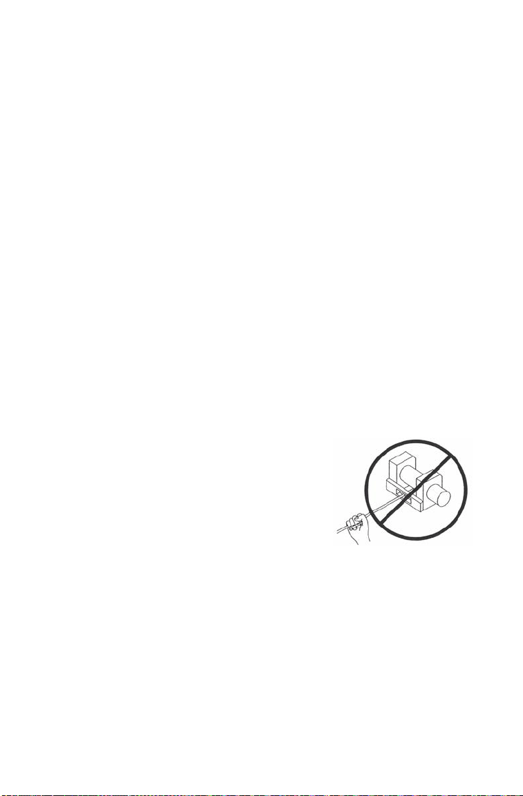
74
WINCH GUIDE
Winch Safety Precautions
10. Always apply your vehicle’s park brake and/or park mechanism to
hold the vehicle in place during winching. Use wheel chocks if
needed.
11. Always align the vehicle and winch with the load directly in front of
the vehicle as much as possible. Avoid winching with the winch
cable at an angle to the winching vehicle’s centerline whenever
possible.
12. If winching at an angle is unavoidable, follow these precautions:
A. Look at the winch drum occasionally. Never let the winch cable “stack”
or accumulate at one end of the winch drum. Too much winch cable at
one end of the winch drum can damage the winch and the winch cable.
B. If stacking occurs, stop winching. Follow step 15 on page 80 to feed
and rewind the cable evenly before continuing the winch operation.
13. Never winch up or down at sharp angles. This can destabilize the
winching vehicle and possibly cause it to move without warning.
14. Never attempt to winch loads that weigh more than the winch’s
rated capacity.
15. The winch motor may become hot during winch use. If you winch
for more than 45 seconds, or if the winch stalls during operation,
stop winching and permit the winch to cool down for 10 minutes
before using it again.
16. Never touch, push, pull or straddle the
winch cable while winching a load.
17. Never let the winch cable run through
your hands, even if wearing heavy
gloves.

75
WINCH GUIDE
Winch Safety Precautions
18. Never release the clutch on the winch when the winch cable is under
load.
19. Never use the winch for lifting or transporting people.
20. Never use the winch to hoist or suspend a vertical load.
21. Never immerse or submerse your winch in water. Take your winch
to your dealer for service if this occurs.
22. Always inspect your winch and winch cable before each use.
23. Never winch the hook fully into the winch. This can cause damage
to winch components.
24. Unplug the remote control from the vehicle when the winch is not in
use to prevent inadvertent activation and use by unauthorized
persons.
25. Never grease or oil the winch cable. This will cause the winch cable
to collect debris that will shorten the life of the cable.
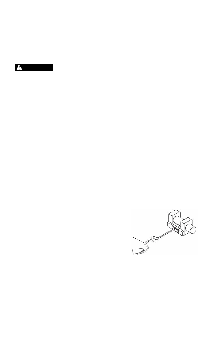
76
WINCH GUIDE
Winch Operation
Read the Winch Safety Precautions in the preceding pages before using
your winch.
Tip: Consider practicing the operation and use of your winch before you actually
need to use it in the field.
Improper winch use can result in SEVERE INJURY or DEATH. Always
follow all winch instructions and warnings in this manual.
Each winching situation is unique.
• Take your time to think through the winching you are about to do.
• Proceed slowly and deliberately.
• Never hurry or rush during winching.
• Always pay attention to your surroundings.
• You may need to change your winching strategy if it is not working.
• Always remember that your winch is very powerful.
• There are simply some situations that you and your winch will not be able
to deal with. Do not be afraid to ask others to help when this happens.
1. Always inspect the vehicle, winch, winch cable and winch controls
for any signs of damage or parts in need of repair or replacement
before each use. Pay particular attention to the first 3 feet (1 meter)
of winch cable if the winch is being used (or has been used) for lift-
ing an accessory plow assembly. Promptly replace any worn or
damaged cable.
2. Never operate a winch or a vehicle in need of repair or service.
3. Always apply your
vehicle’s park brake and/or
park mechanism to hold
the vehicle in place during
winching. Use wheel
chocks if needed.
WARNING
Hook Strap
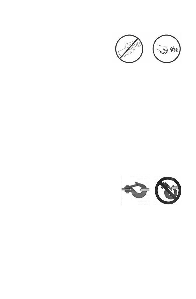
77
WINCH GUIDE
Winch Operation
4. Always use the hook strap when
handling the hook.
WARNING! Never put your fingers into
the hook. This could lead to SEVERE
INJURY.
A. Attach the hook itself onto the
load or use a tow strap or chain
to secure the load to the winch
cable.
Tip: A “tow strap” is NOT intended to stretch. A “recovery strap” is designed to
stretch.
WARNING! Never use a recovery strap when winching due to the excessive
energy that can be released if the winch cable breaks. This can result in
SEVERE INJURY or DEATH. See the Shock Loading section on page 82.
B. Never hook the winch cable back onto itself. This will damage the
winch cable and may result in winch cable failure.
WARNING! Replace the winch cable at the first sign of damage to prevent
SEVERE INJURY or DEATH in the event of failure. For your safety, always
replace POLARIS winch parts (including the cable) with genuine POLARIS
replacement parts available at your authorized POLARIS dealer.
C. If possible, keep the winch cable aligned with the centerline of the
winching vehicle. This will help the spooling of the winch cable and
reduce the load on the fairlead.
D. If freeing a stuck vehicle by attaching to a tree, use an item such as a
tow strap to avoid damaging the tree during winch operation. Sharp
cables and chains can damage and even kill trees. Please remember
to TreadLightly® (treadlightly.org).
E. Before operating the winch, be sure
that the safety latch on the winch
cable hook is fully seated when the
load is attached.
F. Never operate your winch with a
damaged hook or latch. Always
replace damaged parts before using
the winch.
NO YES
NO
YES

78
WINCH GUIDE
Winch Operation
5. Never remove the hook strap from the hook.
6. Release the winch clutch and pull out the winch cable.
7. Pulling out as much cable as possible maximizes the winch’s pulling
capacity. Always be sure that at least five (5) full turns of winch
cable are wrapped around the winch drum at all times. The friction
provided by this wrapped cable allows the drum to pull on the
winch cable and move the load.
8. Read and adhere to the following information for winch damping to
ensure safe winch use.
A. In order to absorb energy that could be released by a winch cable
failure, always place a “damper” on the winch cable. A damper can be
a heavy jacket, tarp, or other soft, dense object. A damper can absorb
much of the energy released if a winch cable breaks when winching.
Even a tree limb can help as a damper if no other items are available to
you.
B. Lay the damper on top of the mid-point of the winch cable length that is
spooled out.
C. On a long pull, it may be necessary to stop winching so that the
damper can be repositioned to the new mid-point of the winch cable.
Always release the tension on the winch cable before repositioning the
damper.
D. Avoid being directly in line with the winch cable whenever possible.
Also, never permit others to stand near or in line with the winch cable
during winch operation.
9. Never hook the winch cable back onto itself. This will damage the
winch cable and may result in winch cable failure.
10. Never use straps, chains or other rigging items that are damaged or
worn.

79
WINCH GUIDE
Winch Operation
11. The ONLY time a winch-equipped vehicle should be moving when
using the winch is when that vehicle itself is stuck. The winch-
equipped vehicle should NEVER be in motion to “shock” load the
winch cable in an attempt to move a second stuck vehicle. See the
Shock Loading section on page 82. For your safety, always follow
these guidelines when winching a vehicle free:
A. Release the winch clutch and spool out the necessary length of winch
cable.
B. Align the winch cable as close as possible to the winching vehicle’s
centerline.
C. Attach the winch cable hook to the anchor point or the stuck vehicle’s
frame following instructions in this manual.
D. Re-engage the clutch on the winch.
E. Slowly winch in the slack in the winch cable.
F. Select the proper vehicle gear to propel the stuck vehicle in the
direction of winching.
G. Shift to the lowest gear available on the stuck vehicle.
H. Slowly and carefully apply vehicle throttle and winch together to free
the vehicle.
I. Stop winching as soon as the stuck vehicle is able to propel itself
without the help of the winch.
J. Detach the winch cable hook.
K. Rewind the winch cable evenly back onto the winch drum following the
instructions in this manual.
12. Never attempt to winch another stuck vehicle by attaching the
winch cable to a suspension component, brush guard, bumper or
cargo rack. Vehicle damage may result. Instead, attach the winch to
a strong portion of the vehicle frame or hitch.
13. Extensive winching will run down the battery on the winching
vehicle. Let the winching vehicle’s engine run while operating the
winch to prevent the battery from running low if winching for long
periods.

80
WINCH GUIDE
Winch Operation
14. The winch motor may become hot during winch use. If you winch
for more than 45 seconds, or if the winch stalls during operation,
stop winching and permit the winch to cool down for 10 minutes
before using it again.
15. After winching is complete, especially if winching at an angle, it
may be necessary to re-distribute the winch cable across the winch
drum. You will need an assistant to perform this task.
A. Release the clutch on the winch.
B. Feed out the winch cable that is unevenly bunched up in one area.
C. Re-engage the winch clutch.
D. Have an assistant pull the winch cable tightly with about 100 lbs. (45
kg) of tension using the hook strap.
E. Slowly winch the cable in while your assistant moves the end of the
winch cable back and forth horizontally to evenly distribute the winch
cable on the drum.
F. Doing this reduces the chances of the winch cable “wedging” itself
between lower layers of winch cable.
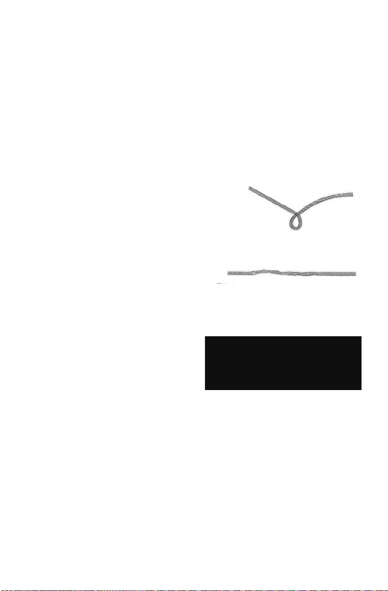
81
WINCH GUIDE
Winch Cable Care
For your safety, always replace POLARIS winch parts (including the
cable) with genuine POLARIS replacement parts available at your
authorized POLARIS dealer.
WARNING! Use of worn or damaged cable could lead to sudden failure and
SEVERE INJURY.
1. Always inspect your winch before each use. Inspect for worn or
loose parts including mounting hardware. Never use the winch if
any part needs repair or replacement.
2. Always inspect your winch cable before each use. Inspect for worn
or kinked winch cable.
A. A kinked winch cable made of
wire rope is shown at right. Even
after being “straightened out,”
this cable has already been
permanently and severely
damaged. Promptly discontinue
use of a winch cable in this
condition.
B. A kinked winch cable made of
wire rope that has been
“straightened out” is shown at
right. Even though it may look
usable, the cable has been
permanently and severely damaged. It can no longer transmit the load
that it could prior to kinking. Promptly discontinue use of a winch cable
in this condition.
C. A winch cable made of
synthetic rope should be
inspected for signs of fraying.
Replace the cable if fraying is
observed (shown at right).
Promptly discontinue use of a
winch cable in this condition.
D. Also replace the winch cable if there are fused or melted fibers. Such
an area of the synthetic rope will be stiff and appear smooth or glazed.
Promptly discontinue use of a winch cable in this condition.
A
B
C

82
WINCH GUIDE
Shock Loading
WARNING! Your winch cable is very strong but it is NOT designed for dynamic,
or “shock” loading. Shock loading may tension a winch cable beyond its strength
and cause the cable to break. The end of a broken winch cable under such high
loading can cause SEVERE INJURY or DEATH to you and other bystanders.
Winch cables are designed to NOT absorb energy. This is true of both
wire-rope and synthetic-rope winch cables.
1. Never attempt to “jerk” a load with the winch. For example, never
take up slack in the winch cable by moving the winching vehicle in
an attempt to move an object. This is a dangerous practice. It gener-
ates high winch cable loads that may exceed the strength of the
cable. Even a slowly moving vehicle can create large shock loads in
a winch cable.
WARNING! SEVERE INJURY or DEATH can result from a broken winch cable.
2. Never quickly turn the winch ON and OFF repeatedly (“jogging”).
This puts extra load on the winch, winch cable, and generates
excessive heat from the motor. This is a form of shock loading.
3. Never tow a vehicle or other object with your winch. Towing an
object with a winch produces shock loading of the cable even when
towing at slow speeds. Towing from a winch also positions the
towing force high on the vehicle. This can cause instability of the
vehicle and possibly lead to an accident.
4. Never use recovery straps with your winch. Recovery straps are
designed to stretch and can store energy. This stored energy in the
recovery strap is released if a winch cable fails making the event
even more hazardous. Similarly, never use elastic “bungie” cords
for winching.
5. Never use the winch to tie down a vehicle to a trailer or other
transportation vehicle. This type of use also causes shock loading
that can cause damage to the winch, winch cable, or vehicles used.
Your winch cable is designed and tested to withstand the loads
produced by the winch motor when operated from a stationary
vehicle. Always remember that the winch and winch cable are NOT
designed for shock loading.

83
WINCH GUIDE
Winch Maintenance and Service Safety
WARNING! Improper or lack of winch maintenance and service could lead to
SEVERE INJURY or DEATH. Always follow all winch instructions and warnings
in this manual.
1. Always inspect your winch before each use. Inspect for worn or
kinked winch cable. Also inspect for worn or loose parts including
mounting hardware.
2. Permit your winch motor to cool down prior to servicing your
winch.
3. Never work on your winch without first disconnecting the battery
connections to prevent accidental activation of the winch.
4. For your safety, always replace POLARIS winch parts (including
the cable) with genuine POLARIS replacement parts available at
your authorized POLARIS dealer.
5. Some winch models use wire rope as the winch cable. Other
winches use a specially designed synthetic rope as the winch cable.
6. Never replace a synthetic-rope winch cable with a consumer-grade
polymer rope such as can be purchased in a hardware store.
Although they may look similar, they are NOT alike. A polymer
rope not designed for winch use will stretch and store excessive
energy when winching.
WARNING! Failure of a stretched rope under winching conditions will release
all of the stored energy. This will increase the chances of SEVERE INJURY or
DEATH.

84
EMISSION CONTROL SYSTEMS
Noise Emission Control System
Do not modify the engine, intake or exhaust components, as doing so
may affect compliance with governmental noise level requirements.
Spark Arrester
Your POLARIS vehicle has a spark arrester that was designed for on-
road and off-road operation. It is required that this spark arrester remain
installed and functional when the vehicle is operated.
Exhaust Emission Control System
Exhaust emissions are controlled by engine design. An electronic fuel
injection (EFI) system controls fuel delivery. The engine and EFI
components are set at the factory for optimal performance and are not
adjustable.
Electromagnetic Interference
This spark ignition system complies with Canadian ICES-002.
This vehicle complies with the EMC requirements of European
directive 2014/30/EU.
Non-ionizing Radiation: This vehicle emits some electromagnetic
energy. People with active or non-active implantable medical devices
(such as heart monitoring or controlling devices) should review the
limitations of their device and the applicable electromagnetic standards
and directives that apply to this vehicle.

85
MAINTENANCE
Periodic Maintenance Chart
Careful periodic maintenance will help keep your vehicle in the safest,
most reliable condition. Inspection, adjustment and lubrication of
important components are explained in the periodic maintenance chart.
Inspect, clean, lubricate, adjust and replace parts as necessary. When
inspection reveals the need for replacement parts, use genuine
POLARIS parts available from your POLARIS dealer.
Record maintenance and service in the Maintenance Log beginning on
page 144.
Service and adjustments are important for proper vehicle operation. If
you're not familiar with safe service and adjustment procedures, have a
qualified dealer perform these operations.
Vehicles subjected to heavy or severe use patterns must be inspected and
serviced more frequently.
Severe Use Definition
• Frequent immersion in mud, water or sand
• Frequent or prolonged operation in dusty environments
• Racing or race-style high RPM use
• Prolonged low speed, heavy load operation
• Extended idle
• Short trip cold weather operation
Pay special attention to the oil level. A rise in oil level during cold
weather can indicate contaminants collecting in the oil sump or
crankcase. Change oil immediately if the oil level begins to rise.
Monitor the oil level, and if it continues to rise, discontinue use and
determine the cause or see your POLARIS dealer.

86
MAINTENANCE
Periodic Maintenance Chart
Maintenance Chart Key
WARNING! Improperly performing the procedures marked with a “D” could
result in component failure and lead to serious injury or death. Have an
authorized POLARIS dealer perform these services.
Perform all services at whichever maintenance interval is reached first.
Symbol Description
► Perform these operations more often for vehicles subjected to severe use.
D Have an authorized POLARIS dealer perform these services.
Item Maintenance Interval
(whichever comes first)
Remarks
Hours Calendar Miles (Km)
Steering
Pre-Ride
Inspect and make
adjustments as needed.
See Pre-Ride Checklist on
page 54.
Front suspension
Rear suspension
Tires
Brake fluid level
Brake pedal travel
Brake system
Wheels/fasteners
Frame fasteners
Engine oil level
Intake pre-filters
Winch (if
equipped)
- - See pages 73-83
Coolant - Daily - Check level
Headlamp/tail
lamp
- Daily - Check operation; apply
dielectric grease if replacing
► Air filter,
main element
- Weekly - Inspect; replace as needed
►
D
Brake pad wear 10 H Monthly 100 (160) Inspect periodically
► Engine breather 25 H Monthly 150 (250) Inspect; replace if necessary
Battery 25 H Monthly 250 (400) Check terminals; clean; test
Fuel System 25 H Monthly - Inspect; cycle key to
pressurize fuel pump; check
lines and fittings for leaks and
abrasion

87
MAINTENANCE
Periodic Maintenance Chart
► Perform these procedures more often for vehicles subjected to severe use.
D Have an authorized POLARIS dealer perform these services.
Item Maintenance Interval
(whichever comes first)
Remarks
Hours Calendar Miles (Km)
► Engine oil change 25 H 1 M - Break-in oil and filter change
► Demand drive fluid 25 H 1 M - Break-in oil level check
► Transmission oil
(main gearcase)
25 H 1 M - Break-in oil level check
► Throttle cable 50 H 6 M 300 (500) Inspect; adjust; lubricate;
replace if necessary
Throttle body air
intake ducts/flange
50 H 6 M 300 (500) Inspect duct for proper seal-
ing/air leaks
► General lubrication 50 H 3 M 500 (800) Lubricate all fittings, pivots,
cables, etc.
► Oil lines, fasteners
(if equipped)
50 H 6 M 500 (800) Inspect for leaks and loose
fittings
Shift Linkage 50 H 6 M 500 (800) Inspect, lubricate, adjust
D Steering 50 H 6 M 500 (800) Lubricate
► Front Suspension 50 H 6 M 500 (800) Lubricate
► Rear Suspension 50 H 6 M 500 (800) Lubricate
Cooling system 50 H 6 M 500 (800) Inspect coolant strength
seasonally; pressure test
system yearly
► Engine oil change 100 H 6 M - Change the oil and filter
D Fuel system 100 H 12 M 600 (1000) Cycle key to pressurize fuel
pump; check for leaks at fill
cap, fuel lines/rail and fuel
pump; replace lines every
two years
► Spark plug 100 H 12 M 600 (1000) Inspect; replace as needed
► Demand drive fluid 100 H 12 M - Change fluid
► Transmission oil
(main gearcase)
100 H 12 M - Change fluid
► Radiator 100 H 12 M 1000 (1600) Inspect; clean external
surfaces
► Cooling Hoses 100 H 12 M 1000 (1600) Inspect for leaks
► Engine mounts 100 H 12 M 1000 (1600) Inspect

88
MAINTENANCE
Periodic Maintenance Chart
► Perform these procedures more often for vehicles subjected to severe use.
D Have an authorized POLARIS dealer perform these services.
Item Maintenance Interval
(whichever comes first)
Remarks
Hours Calendar Miles (Km)
Exhaust muffler/
pipe
100 H 12 M 1000 (1600) Inspect
► Wiring 100 H 12 M 1000 (1600) Inspect for wear, routing,
security; apply dielectric
grease to connectors
subjected to water, mud, etc.
D Clutches (drive
and driven)
100 H 12 M 1000 (1600) Inspect; clean; replace worn
parts
Drive belt 100 H 12 M 1000 (1600) Inspect; replace as needed
D Front wheel
bearings
100 H 12 M 1000 (1600) Inspect; replace as needed
D Brake fluid 200 H 24 M 2000 (3200) Change every two years
Spark arrester 300 H 36 M 3000 (4800) Clean out
► Coolant - 60 M - Replace coolant
► Valve clearance 500 H - 5000 (8000) Inspect; adjust as needed
D Toe adjustment - Inspect periodically; adjust
when parts are replaced
Headlight aim - Adjust as needed
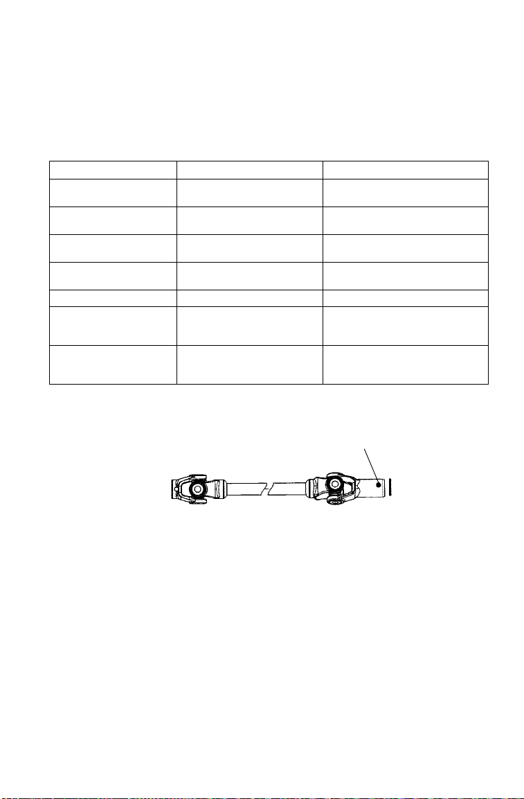
89
MAINTENANCE
Lubrication Recommendations
Check and lubricate all components at the intervals outlined in the
Periodic Maintenance Chart beginning on page 85, or more often under
severe use, such as wet or dusty conditions. Items not listed in the chart
should be lubricated at the general lubrication interval.
Item Lube Method
Engine Oil PS-4 5W-50 4-Cycle Oil Add to proper level on dipstick.
See page 92.
Brake Fluid DOT 4 Brake Fluid Maintain level between fill lines.
See page 112.
Transmission Oil
(Main Gearcase)
AGL Gearcase Lubricant &
Transmission Fluid
See page 97.
Demand Drive Fluid
(Front Gearcase)
Demand Drive Fluid See page 95.
Prop Shaft U-Joint Grease Locate fittings and grease.
Rear Control Arm Pivot
Bushings, Front A-Arm
Bushings
All Season Grease or grease
conforming to NLGI No. 2
Locate fittings and grease.
Stabilizer Bar Bushings,
Tie Rod Bushings, Ball
Joint Boots
All Season Grease or grease
conforming to NLGI No. 2
Locate fittings and grease.
Prop Shaft
Grease Fitting
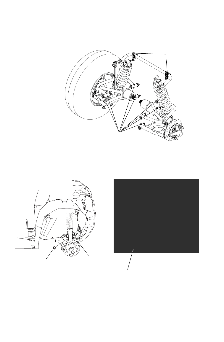
90
MAINTENANCE
Lubrication Recommendations
Rear Control
Arm Pivot
Bushings
Stabilizer Bar
Bushings
Front A-Arm
Bushing
Tie Rod
Bushing
Ball Joint
Boot

91
MAINTENANCE
Engine Oil
Oil Recommendations
POLARIS recommends the use of POLARIS PS-4 Full Synthetic 5W-
50 4-cycle oil for this engine.
WARNING! Vehicle operation with insufficient, deteriorated, or contaminated
engine oil will cause accelerated wear and may result in engine seizure,
accident, and injury. Always perform the maintenance procedures as outlined in
the Periodic Maintenance Chart.
Oil may need to be changed more frequently if POLARIS PS-4 engine
oil is not used. Follow the manufacturer's recommendations for ambient
temperature operation. See page 134 for the part numbers of POLARIS
products.
NOTICE: Mixing brands or using a non-recommended oil may cause serious
engine damage. Always use the recommended oil. Never substitute
or mix oil brands.
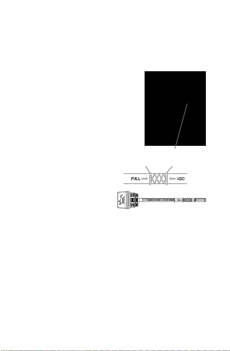
92
MAINTENANCE
Engine Oil
Always check and change the oil at the intervals outlined in the Periodic
Maintenance Chart beginning on page 85. Always use the recommended
engine oil. See page 91.
Oil Check
The oil dipstick and fill tube is located on
the engine, behind the passenger seat.
Access the dipstick through the right rear
wheel well.
1. Position the vehicle on a level surface.
2. Place the transmission in PARK.
3. Always clean away all dirt and debris
from the dipstick area before removing
the dipstick. Remove the dipstick.
Wipe it dry with a clean cloth.
4. Reinstall and tighten the dipstick.
5. Remove the dipstick and
check the oil level.
6. Add the recommended fluid as
needed. Maintain the oil level
in the safe range between the
FULL and ADD marks. Do
not overfill.
7. Reinstall and tighten the
dipstick.
Dipstick
Full
Add

93
MAINTENANCE
Engine Oil
Oil and Filter Change
Always check and change the oil at the intervals outlined in the Periodic
Maintenance Chart beginning on page 85. Always change the oil filter
whenever changing oil.
The engine drain plug is located on the
bottom of the crankcase.
1. Position the vehicle on a level surface.
Place the transmission in PARK.
Apply the brakes.
2. Start the engine. Allow it to idle for
two to three minutes. Stop the engine.
3. Clean the area around the drain plug.
CAUTION! Hot oil can cause burns to skin. Do
not allow hot oil to contact skin.
4. Place a drain pan beneath engine
crankcase and remove the drain plug.
5. Allow the oil to drain completely.
6. Reinstall the sealing washer on the drain plug.
Tip: The sealing surfaces on drain plug and crankcase should be clean and free
of burrs, nicks or scratches.
7. Reinstall the drain plug. Torque to 12 ft. lbs. (16 Nm).
Drain Plug Access

94
MAINTENANCE
Engine Oil
Oil and Filter Change
8. Using a cap-style oil filter
wrench, turn the filter
counter-clockwise to remove
it.
9. Using a clean dry cloth, clean
the filter sealing surface on
the crankcase. Make sure the
old filter o-ring is completely
removed.
10. Lubricate the o-ring on the
new filter with a film of fresh
engine oil. Check to make
sure the o-ring is in good
condition.
11. Install the new filter and turn by hand until the filter gasket contacts
the seali
ng surface, then turn and additional 3/4 turn.
12. Always clean away all dirt and debris from the dipstick area before
removing the dipstick. Remove the dipstick and fill the sump with
two quarts (1.9 l) of recommended oil.
13. Reinstall and tighten the dipstick.
14. Make sure the transmission is in PARK. Apply the brakes.
15. Start the engine. Allow it to idle for one to two minutes.
16. Stop the engine. Inspect for leaks.
17. Re-check the oil level on the dipstick and add oil as necessary to
bring the level to the upper mark on the dipstick.
18. Dispose of used filter and oil properly.
Oil Filter
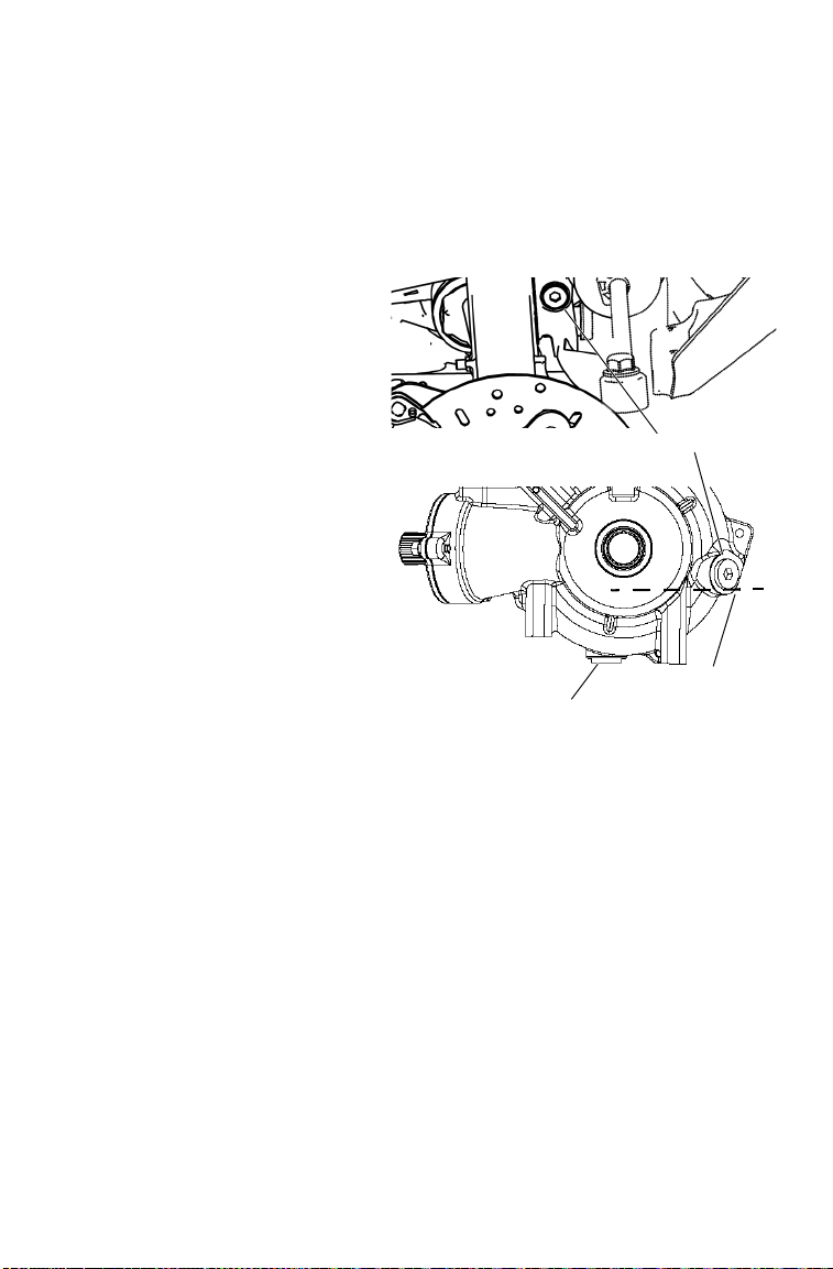
95
MAINTENANCE
Gearcases
Demand Drive Unit (Front Gearcase)
Always check and change the fluid at the intervals outlined in the
Periodic Maintenance Chart beginning on page 85. Refer to the
Gearcase Specifications Chart on page 98 for recommended lubricants,
capacities and torque specifications.
Fluid Check
The fill plug is located on the
bottom right side of the
demand drive unit. Access the
fill plug through the right front
wheel well. Maintain the fluid
level even with the bottom
thread of the fill plug hole.
1. Position the vehicle on a
level surface.
2. Remove the fill plug.
Check the fluid level.
3. Add the recommended
fluid to the bottom thread
of the fill plug hole.
4. Reinstall the fill plug.
Torque to specification.
Fill Level
Fill Plug
Drain Plug

96
MAINTENANCE
Gearcases
Demand Drive Unit (Front Gearcase)
Fluid Change
The drain plug is located on the bottom of the gearcase.
1. Remove the fill plug.
2. Place a drain pan under the drain plug.
3. Remove the drain plug. Allow the fluid to drain completely.
4. Clean the drain plug.
5. Reinstall the drain plug. Torque to specification.
6. Add the recommended fluid to the bottom thread of the fill plug
hole.
7. Reinstall the fill plug. Torque to specification.
8. Check for leaks. Discard used fluid properly.

97
MAINTENANCE
Gearcases
Transmission (Main Gearcase)
Always check and change the fluid at the intervals outlined in the
Periodic Maintenance Chart beginning on page 85. Refer to the
Gearcase Specifications Chart on page 98 for recommended lubricants,
capacities and torque specifications.
Fluid Check
The fill plug is located on the rear of
the gearcase. Maintain the fluid level at
the bottom of the fill plug hole.
1. Position the vehicle on a level
surface.
2. Remove the fill plug. Check the
fluid level.
3. Add the recommended fluid to the
bottom of the fill plug hole. Do not
overfill.
4. Reinstall the fill plug. Torque to
specification.
Fluid Change
The drain plug is located on the bottom
of the gearcase between the rear tires.
Access the drain plug through the drain
hole in the skid plate.
1. Remove the fill plug.
2. Place a drain pan under the drain
plug. Remove the drain plug. Allow the fluid to drain completely.
3. Clean the drain plug. Reinstall the drain plug. Torque to
specification.
4. Add the recommended fluid to the bottom of the fill plug hole. Do
not overfill.
5. Reinstall the fill plug. Torque to specification.
6. Check for leaks. Discard used fluid properly.
Fill Plug
Drain Plug
(between rear tires)

98
MAINTENANCE
Gearcases
Gearcase Specification Chart
Use of other fluids may result in improper operation of components. See
page 134 for the part numbers of POLARIS products.
Spark Plug
Spark Plug Gap/Torque
NOTICE: Using non-recommended spark plugs can result in serious engine
damage. Always use POLARIS-recommended spark plugs. Refer to
the specifications section beginning on page 132.
Spark plug condition is indicative of engine operation. The spark plug
firing end condition should be read after the engine is warmed up and
the vehicle is driven at higher speeds. Immediately check the spark plug
for correct color. See page 99.
CAUTION! A hot exhaust system and engine can cause burns. Wear
protective gloves when removing a spark plug for inspection.
Gearcase Lubricant Capacity Fill Plug
Torque
Drain Plug/
Level Check
Plug Torque
Transmission
(Main Gearcase)
AGL Gearcase
Lubricant &
Transmission
Fluid
44 oz. (1300 ml) 10-14 ft-lbs
(14-19 Nm)
10-14 ft-lbs
(14-19 Nm)
Demand Drive Unit
(Front Gearcase)
Demand Drive
Fluid
9 oz. (265 ml) 8-10 ft-lbs
(11-13.6 Nm)
8-10 ft-lbs
(11-13.6 Nm)
Electrode Gap New Plug Torque Used Plug Torque
0.8 +/- 0.1 mm 9 ft. lbs. (12 Nm) 9 ft. lbs. (12 Nm)

99
MAINTENANCE
Spark Plug
Spark Plug Removal and Replacement
1. Remove the cargo box access panel.
2. Remove the spark plug cap.
3. Using the spark plug wrench provided in the tool kit, remove the
plug by rotating it counter-clockwise.
4. Reverse the procedure for spark plug installation. Torque to
specification. See page 98.
Spark Plug Condition
Normal Plug
The normal insulator tip is gray, tan or light brown. There will be few
combustion deposits. The electrodes are not burned or eroded. This
indicates the proper type and heat range for the engine and the service.
Wet Fouled Plug
The wet fouled insulator tip is black. A damp oil film covers the firing
end. There may be a carbon layer over the entire nose. Generally, the
electrodes are not worn. General causes of fouling are excessive oil, use
of non-recommended injection oil or incorrect throttle body
adjustments.
100
MAINTENANCE
Fuses
If the engine stops or will not start, or if you experience other electrical
failures, a fuse may need replacement. Locate and correct any short
circuits that may have caused the blown fuse, then replace the fuse.
The fuse box is located under the seat. Spare fuses are provided in the
fuse box.
Main Fuse Feature Supported
20A Lights: Headlights, Taillights
20A Drive: AWD
20A Accessory: Winch Switch, 12V Power Receptacle
10A Fuel Pump
20A Electronic Engine Control, Starting
30A Engine Control
10A Constant Vehicle Power
15A Fan Circuit Braker - Auto Reset
Fuse Box

101
MAINTENANCE
Fuses
1. Remove the seat to access
the fuse box.
2. Squeeze the cover release
tabs inward and remove the
fuse box cover.
3. Remove the suspect fuse
from the fuse panel. If the
fuse is blown, install a new
fuse with the same amperage
rating.
4. Reinstall the fuse box cover.
5. Reinstall the seat.
Release Tabs

102
MAINTENANCE
Cooling System
Operation
The engine coolant level is controlled or maintained by the recovery
system. The recovery system components are the overflow bottle,
radiator filler neck, radiator pressure cap and connecting hose.
As coolant operating temperature increases, the expanding (heated)
excess coolant is forced out of the radiator, past the pressure cap, and
into the overflow bottle. As engine coolant temperature decreases, the
contracting (cooled) coolant is drawn back up from the tank, past the
pressure cap, and into the radiator.
Tip: Some coolant level drop on new vehicles is normal as the system is purging
itself of trapped air. Observe coolant levels and maintain as recommended
by adding coolant to the overflow bottle.
Adding or Changing Coolant
POLARIS recommends the use of POLARIS Antifreeze 50/50 Premix.
This antifreeze is already premixed and ready to use. Do not dilute with
water. See page 134 for the part numbers of POLARIS products.
To ensure that the coolant maintains its ability to protect the engine, we
recommend that the system be completely drained every five (5) years
and fresh Antifreeze 50/50 Premix added.
Any time the cooling system has been drained for maintenance or repair,
replace the coolant with fresh Antifreeze 50/50 Premix.
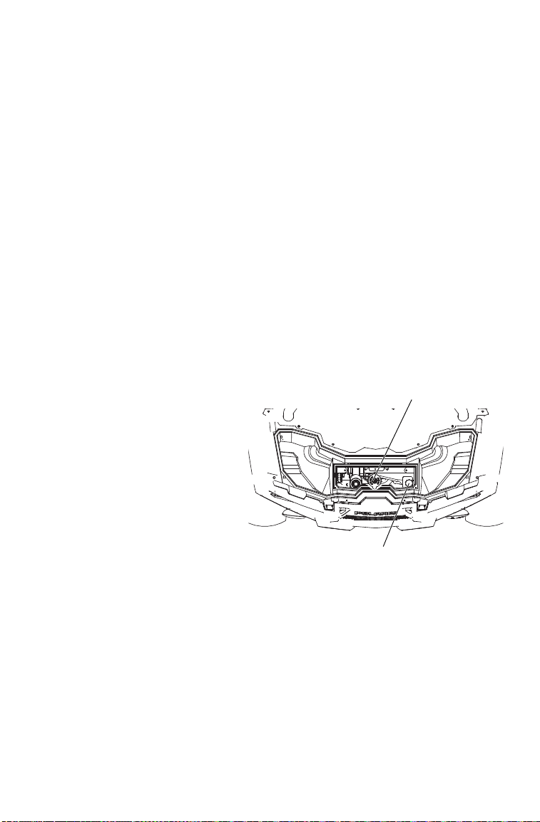
103
MAINTENANCE
Cooling System
Radiator and Cooling Fan
Always check and clean the screen and radiator fins at the intervals
outlined in the Periodic Maintenance Chart beginning on page 85. Do
not obstruct or deflect air flow through the radiator by installing
unauthorized accessories in front of the radiator or behind the cooling
fan. Interference with the radiator air flow can lead to overheating and
consequent engine damage.
NOTICE: Washing the vehicle with a high-pressure hose could damage the
radiator fins and impair the radiator's effectiveness. Using a high-
pressure system is not recommended.
Radiator Coolant Level
This procedure is required only if the cooling system has been drained
for maintenance and/or repair. But if the overflow bottle has run dry, the
level in the radiator should also be inspected.
CAUTION! Escaping steam can cause burns. Never remove the pressure cap
while the engine is warm or hot. Always allow the engine to cool before
removing the pressure cap.
1. Remove the front box
cover and access panel.
See page 27.
2. Slowly remove the
radiator cap.
3. View the coolant level
through the opening.
4. Use a funnel and slowly
add coolant as needed.
Tip: Use of a non-standard
pressure cap will not allow
the recovery system to
function properly. See your
POLARIS dealer for the correct replacement part.
Radiator Cap
Overflow Bottle
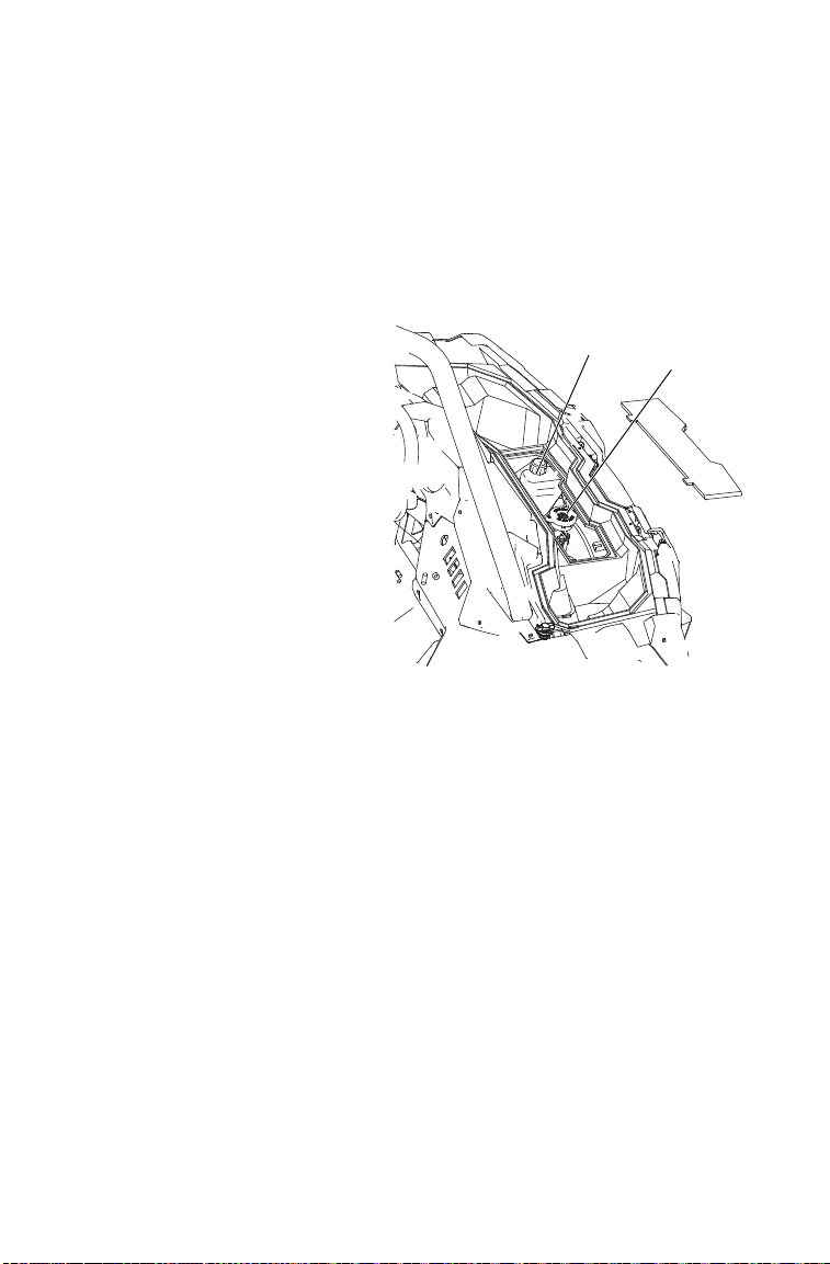
104
MAINTENANCE
Cooling System
Coolant Level
Always check and change the coolant at the intervals outlined in the
Periodic Maintenance Chart beginning on page 85. Maintain the coolant
level between the minimum and maximum marks on the bottle (when
the fluid is cool). The coolant level in the bottle can be viewed through
the left front wheel well or in the compartment in the front box.
1. Position the vehicle on a
level surface.
2. View the coolant level in
the overflow bottle.
3. If the coolant level is
below the safe operating
range, remove the cap and
use a funnel to add
coolant through the
opening. Reinstall the cap.
Tip: If coolant must be added
often, or if the overflow bottle
runs completely dry, there
may be a leak in the system.
Have the cooling system
inspected by your POLARIS
dealer.
Radiator
Cap
Overflow
Bottle

105
MAINTENANCE
POLARIS Variable Transmission (PVT) System
Failure to comply with the instructions in this warning can result in severe injury
or death.
Do not modify any component of the PVT system. Doing so may reduce its
strength so that a failure may occur at a high speed. The PVT system has been
precision balanced. Any modification will cause the system to be out of balance,
creating vibration and additional loads on components.
The PVT system rotates at high speeds, creating large amounts of force on
clutch components. As the owner, you have the following responsibilities for
your own safety and the safety of others:
• Always follow all recommended maintenance procedures. Always look for and
remove debris inside and around the clutch and vent system when replacing
the belt.
• See your POLARIS dealer as outlined in the owner's manual.
• This PVT system is intended for use on POLARIS products only. Do not install
it in any other product.
• Always make sure the PVT housing is securely in place during operation.
WARNING

106
MAINTENANCE
POLARIS Variable Transmission (PVT) System
Belt Replacement/Debris Removal
If a belt fails, always clean any debris from the PVT intake and outlet
duct and from the clutch and engine compartments when replacing the
belt.
WARNING! Failure to remove ALL debris when replacing the belt could result in
vehicle damage, loss of control and severe injury or death.
1. Allow hot components to cool before performing this procedure.
2. Remove the clutch cover screws and open the clutch cover. Remove
all debris wrapped in and around the PVT system.
3. Remove all debris from the entire clutch air duct passage.
4. Check for signs of damage to seals on the transmission and engine.
See your POLARIS dealer promptly for service if any seals appear
to be damaged.
Tip: Belt slip is responsible for creating excessive heat that destroys belts,
wears clutch components and causes outer clutch covers to fail. Switch to
low range while operating at slower speeds to extend the life of the PVT
components (belt, cover, etc.).

107
MAINTENANCE
POLARIS Variable Transmission (PVT) System
PVT Drying
There may be some instances when water is accidently ingested into the
PVT system. Use the following instructions to dry it out before
operating.
NOTICE: When washing the vehicle, always avoid spraying water directly
toward the PVT intake duct. See page 127 for recommended
washing procedures.
1. Remove the drain plug from the
bottom of the clutch box. Allow
the water to drain. Reinstall the
drain plug securely.
2. Place the transmission in PARK.
Apply the brakes. Start the
engine.
3. Apply varying throttle for 10-15
seconds to expel the moisture
and air-dry the belt and
clutches. Do not hold the
throttle wide open for more than
10 seconds.
4. Allow the engine RPM to settle
to idle speed. Apply the brakes.
Shift the transmission to the
lowest available range.
5. Test for belt slippage. If the belt slips, repeat the process.
6. Take the vehicle to your POLARIS dealer for service as soon as
possible.
Drain Plug
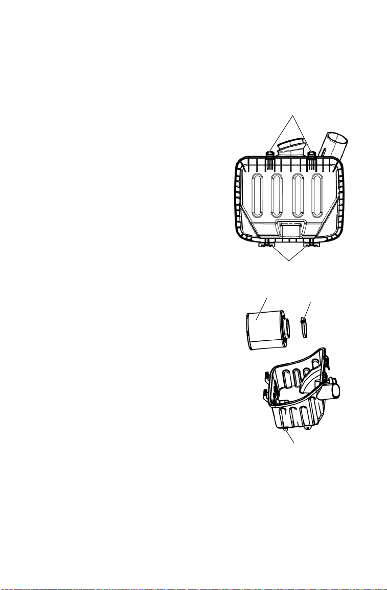
108
MAINTENANCE
Air Filter
Always clean all dirt and debris away from the air box area before
servicing the air filter. Always change the air filter at the intervals
outlined in the Periodic Maintenance Chart beginning on page 85.
1. Remove the cargo box access panel.
2. Clean all dirt and debris from the air
box area BEFORE servicing the air
filter.
3. Unlatch the cover clips and carefully
remove the air box cover.
4. Loosen the air filter clamp and
remove the filter.
NOTICE: Dirt or debris in the air box could
result in severe engine damage.
Always clean all dirt and debris from
the air box before installing the filter.
5. Inspect the air box for dirt, debris, oil
or water. Compress the edges of the
air box drain to drain any water. Clean
the air box thoroughly and wipe it
well with a clean, dry cloth.
6. Reinstall the filter. Install a new filter
if needed. Do not attempt to clean the
air filter. Tighten the clamp.
7. Reinstall the air box cover and secure
the cover clips.
8. Reinstall the access panel.
Cover Clips (2)
Cover Hinges
Filter
Clamp
Air Box Drain

109
MAINTENANCE
Breather Hose Inspection
1. Remove the breather hose clamp at the engine (near the exhaust
outlet).
2. Pull the other end of the breather hose assembly away from the
airbox.
3. Remove the breather hose assembly from the vehicle.
4. Inspect the hoses for debris. Blow gently through the hoses to check
for clogging. Replace a damaged or clogged hose.
5. Check hoses for cracks, deterioration, abrasions or leaks. Replace as
needed.
6. Reinstall the hose assembly and secure the clamp at the engine.
Push the other end of the hose firmly into the airbox fitting.
NOTICE: Operation of the vehicle without breather hoses can cause engine
damage. Always reinstall a breather hose after removing it for
service.
Intake Pre-Filters
The engine intake pre-filter is located on
the right side of the cargo box. The PVT
intake pre-filter is located on the left side
of the cargo box.
Inspect both pre-filters before each use of
the vehicle to ensure adequate air flow. If
necessary, remove the pre-filters and
clean with soapy water. Dry with low
pressure compressed air.
NOTICE: When washing the vehicle, always
avoid spraying water directly
toward the PVT intake duct. See
page 127 for recommended
washing procedures.
Engine Intake
Pre-Filter

110
MAINTENANCE
Spark Arrester
Failure to heed the following warnings while servicing the spark arrester could
result in serious injury or death.
Never run the engine in an enclosed area. Remove any combustible materials
from the area. Wear eye protection and leather work gloves. Do not stand
behind or in front of the vehicle while purging. Never go under the vehicle while
it's inclined.
The exhaust system can get extremely hot. Do not perform service on the spark
arrester while the system is hot. Allow components to cool sufficiently before
proceeding.
Use the following procedure to periodically purge accumulated carbon
from the exhaust pipe/muffler.
1. Remove the arrester clean-out
plug from the bottom of the
muffler.
2. Place the transmission in PARK.
3. Start the engine.
4. Quickly press and release the
throttle pedal several times to
purge carbon from the system.
5. If carbon comes out of the
exhaust, cover or plug the
exhaust outlet. Wear protective
gloves.
6. Lightly tap on the exhaust pipe with a rubber mallet while repeating
step 4.
7. If particles are still suspected to be in the muffler, elevate the rear of
the vehicle one foot (30 cm) higher than the front. Block the wheels.
8. Place the transmission in PARK. Repeat steps 4 to 6 until no more
particles are expelled.
9. Stop the engine. Allow the arrester to cool.
10. Reinstall the arrester plug and remove the exhaust outlet cover or
plug.
WARNING
Exhaust Outlet
Clean-Out
Plug

111
MAINTENANCE
Brakes
The front and rear brakes are hydraulic disc type brakes activated by the
brake pedal. See page 35.
Always check brake pedal travel and the brake fluid reservoir level
before each use of the vehicle. When applied, the brake pedal should
feel firm. Any sponginess would indicate a possible fluid leak or low
brake fluid level, which must be corrected before riding. See page 112
for brake fluid information.
If you discover any irregularities in brake system operation, including
excessive pedal travel, contact your POLARIS dealer for proper
diagnosis and repairs.
WARNING! Operating the vehicle with a spongy brake pedal can result in loss
of braking, which could cause an accident resulting in severe injury or death.
Never operate the vehicle with a spongy-feeling brake pedal.
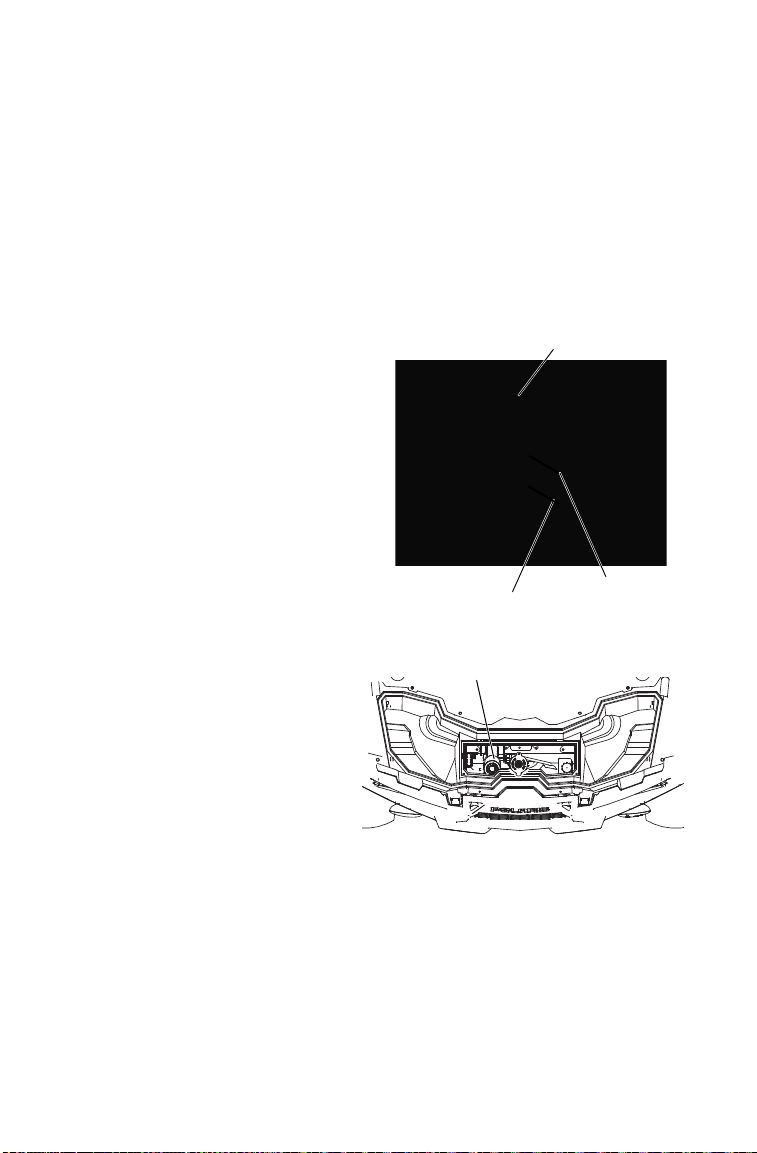
112
MAINTENANCE
Brakes
Brake Fluid
Inspect the level of the brake fluid before each operation. If the fluid
level is low add DOT 4 brake fluid only. See page 134 for the part
numbers of POLARIS products.
WARNING! After opening a bottle of brake fluid, always discard any unused
portion. Never store or use a partial bottle. Brake fluid is hygroscopic, meaning it
rapidly absorbs moisture from the air. The moisture causes the boiling
temperature of the brake fluid to drop, which can lead to early brake fade and
the possibility of accident or severe injury.
Change the brake fluid every two
years and any time the fluid
becomes contaminated, the fluid
level is below the minimum, or if
the type and brand of the fluid in
the reservoir are unknown.
Access the brake fluid reservoir
through the left front wheel well.
1. Position the vehicle on a level
surface.
2. Place the transmission in
PARK.
3. Remove the front box cover
and access panel. See page
27.
4. View the brake fluid level in
the reservoir. The level
should be between the
maximum and minimum
level lines.
5. If the fluid level is lower than
the lower level line, add
brake fluid to the upper line.
6. Apply the brake forcefully for a few seconds and check for fluid
leakage around the fittings.
Brake Fluid
Reservoir
Brake Fluid Reservoir
Maximum
Minimum
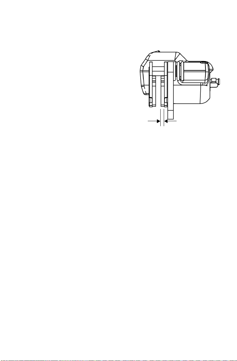
113
MAINTENANCE
Brakes
Brake Inspection
1. Check the brake system for fluid
leaks.
2. Check the brake pedal for
excessive travel or a spongy feel.
3. Check the friction pads for wear,
damage and looseness.
4. Check brake discs for signs of
cracks, excessive corrosion,
warping or other damage. Clean
any grease using an approved
brake cleaner or alcohol.
WARNING! Do not apply WD-40 or any
petroleum product to brake discs. These
types of products are flammable and may
also reduce the friction between the brake
pad and caliper.
5. Inspect the brake disc spline and pad wear surface for excessive
wear. Change pads when worn to 0.030” (0.762 mm).
0.030" (0.762mm)
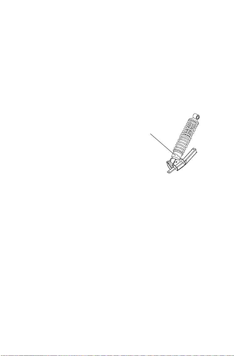
114
MAINTENANCE
Steering Wheel Inspection
Check the steering wheel for specified freeplay and smooth operation at
the intervals outlined in the Periodic Maintenance Chart beginning on
page 85.
1. Position the vehicle on level ground.
2. Lightly turn the steering wheel left and right.
3. There should be 0.8”-1.0” (20-25 mm) of freeplay.
4. If there is excessive freeplay or strange noises, or the steering feels
rough or “catchy,” have the steering system inspected by an
authorized POLARIS dealer.
Rear Spring
The rear shock absorber spring is adjusted
by rotating the adjuster either clockwise
or counter-clockwise to increase or
decrease spring tension.
Accessory springs are available through
your POLARIS dealer.
Adjuster
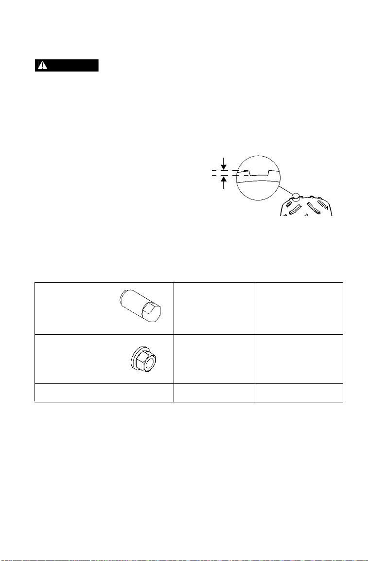
115
MAINTENANCE
Tires
Operating your vehicle with worn tires will increase the possibility of skidding,
loss of control and an accident, which could result in serious injury or death.
Always replace tires when the tread depth measures 1/8” (3 mm) or less.
Improper tire inflation or the use of non-standard size or type of tires may
adversely affect vehicle handling, which could result in vehicle damage or
personal injury. Always maintain proper tire pressure. Always use POLARIS-
approved size and type of tires for this vehicle when replacing tires.
Tire Tread Depth
Always replace tires
when tread depth is
worn to 1/8” (3 mm) or
less.
Axle and Wheel Nut Torque Specifications
Inspect the following items occasionally for tightness, and if they've
been loosened for maintenance service. Do not lubricate the stud or the
lug nut.
Lug Nut
(Aluminum
Wheels)
Front and Rear 30 ft-lbs (41 Nm)
PLUS 1/4 TURN or
90 degrees
2-Piece Flange
Nut (Steel
Wheels)
Front and Rear 27 ft-lbs (37 Nm)
Hub Retaining Nut Front and Rear 80 ft-lbs (108 Nm)
WARNING
1/8" (3 mm)

116
MAINTENANCE
Tires
Wheel Removal
1. Position the vehicle on a level surface.
2. Place the transmission in PARK. Stop the engine.
3. Loosen the wheel nuts slightly.
4. Elevate the side of the vehicle by placing a suitable stand under the
frame.
5. Remove the wheel nuts and washers. Remove the wheel.
Wheel Installation
1. Place the transmission in PARK.
2. Place the wheel on the hub with the valve stem toward the outside
and rotation arrows on the tire pointing toward forward rotation.
WARNING! Improperly installed wheels can adversely affect tire wear and
vehicle handling, which can result in serious injury or death. Always ensure that
all nuts are torqued to specification. Do not service axle nuts that have a cotter
pin installed. See your POLARIS dealer.
3. Attach the wheel nuts and washers and finger-tighten.
4. Carefully lower the vehicle to the ground.
5. Torque the wheel nuts to specification. See page 115.
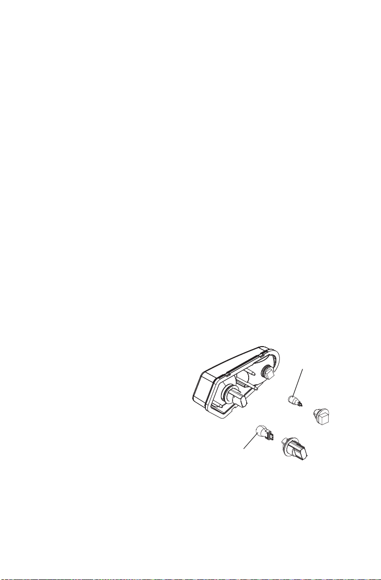
117
MAINTENANCE
Lights
Headlight and taillight lenses become dirty during normal operation.
Clean all lights frequently to ensure a clear field of vision as well as
visibility to other vehicles.
When servicing a halogen lamp, don't touch the lamp with bare fingers.
Oil from your skin leaves a residue, causing a hot spot that will shorten
the life of the lamp.
LED Headlamps (if equipped)
If a headlight becomes damaged or inoperable, the entire headlight
assembly must be replaced.
Tip: If an LED headlamp has moisture or fogging inside, disconnect the wiring
harness from the headlamp(s) for a few days to allow the moisture to clear
out. Do not operate the vehicle at night or in low light conditions without
properly working headlights.
Brake Lights
When the brake pedal is depressed, the brake light comes on. Check the
brake light before each ride.
1. Turn the ignition switch to the HEADLIGHTS ON position.
2. Apply the brakes. The brake light should come on after about 10
mm (0.4 in.) of pedal travel. If the light doesn't come on, check the
bulb.
Taillight/Brake Light/Turn Signal Lamp Replacement
1. Remove the harness
connector from the back
of the light assembly.
2. Pull the lamp out of the
connector to remove it.
3. Install the new lamp.
4. Reinstall the harness
connector.
5. Test the light for proper
operation.
Taillight
Lamp
Turn Signal
Lamp
118
MAINTENANCE
Lights
Front Turn Signal Replacement
If a front turn signal light becomes
inoperable, the lamps cannot be replaced.
Replace the entire signal lamp assembly.
Headlight/Position Light Lamp
Replacement
When servicing a halogen lamp, do not
touch the lamp with bare fingers. Oil
from your skin leaves a residue, causing
a hot spot that will shorten the life of the
lamp. Hold the plastic part of the lamp.
1. Place the transmission in PARK.
2. Open the front rack cover.
3. Remove the plug at the back of the
headlight.
4. Pull the harness plug to disconnect it
from the back of the headlight.
5. Position light: Rotate the socket to
remove it. Go to step 6. Headlamp:
Reach under the bumper and remove
the rubber cover from the back of the
headlight. Turn the collar counter-
clockwise and carefully remove the
collar and socket.
6. Remove the lamp. Apply dielectric
grease to the socket and install a new
lamp.
7. Reverse all steps to reassemble the
headlight.
Position Light
Collar
Socket
Headlamp

119
MAINTENANCE
Lights
Headlight Beam Adjustment
1. Place the vehicle on a level surface with the headlight
approximately 25 ft. (7.6 m) from a wall. Place the transmission in
PARK.
2. Measure the distance from the floor to the center of the headlight
and make a mark on the wall at the same height.
3. Apply the brakes. Turn the ignition
switch to the HEADLIGHTS ON
position.
4. Observe the headlight aim. The most
intense part of the headlight beam
should be aimed 8" (20 cm) below the
mark placed on the wall in step 2.
Include the weight of a rider on the seat
while performing this step.
5. If adjustment is necessary, turn the
headlight adjustment screw to adjust the
beam.
6. Repeat steps 4-5 until the beam is
properly adjusted.
25 ft.
(7.6 m)
8" (20 cm)
XX
Adjustment
Screw

120
MAINTENANCE
Vehicle Immersion
NOTICE: If your vehicle becomes immersed, major engine damage can result
if the machine is not thoroughly inspected. Take the vehicle to your
POLARIS dealer before starting the engine.
If it's impossible to take your vehicle to a dealer before starting it,
follow the steps outlined below.
1. Move the vehicle to dry land.
2. Check the air box. If water is present, dry the air box and replace the
filter with a new filter.
3. Remove the spark plug.
4. Turn the engine over several times.
5. Dry the spark plug and reinstall it, or install a new plug.
6. Attempt to start the engine. If necessary, repeat the drying
procedure.
7. Take the vehicle to your POLARIS dealer for service as soon as
possible, whether you succeed in starting it or not.
8. If water has been ingested into the PVT follow the procedure on
page 107 for drying.

121
MAINTENANCE
Battery
Battery electrolyte is poisonous. It contains sulfuric acid. Serious burns can
result from contact with skin, eyes or clothing.
Antidote:
External: Flush with water.
Internal: Drink large quantities of water or milk. Follow with milk of magnesia,
beaten egg, or vegetable oil. Call physician immediately.
Eyes: Flush with water for 15 minutes and get prompt medical attention.
Batteries produce explosive gases. Keep sparks, flame, cigarettes, etc. away.
Ventilate when charging or using in an enclosed space. Always shield eyes
when working near batteries. KEEP OUT OF REACH OF CHILDREN.
Your vehicle may have either a sealed battery, which requires little
maintenance, or a conventional battery. A sealed battery can be
identified by its flat covers on the top of the battery. A conventional
battery has six filler caps on the top of the battery.
Always keep battery terminals and connections free of corrosion. If
cleaning is necessary, remove the corrosion with a stiff wire brush.
Wash with a solution of one tablespoon baking soda and one cup water.
Rinse well with tap water and dry off with clean shop towels. Coat the
terminals with dielectric grease or petroleum jelly. Be careful not to
allow cleaning solution or tap water into a conventional battery.
WARNING

122
MAINTENANCE
Battery
Improperly connecting or disconnecting battery cables can result in an explosion
and cause serious injury or death. When removing the battery, always
disconnect the negative (black) cable first. When reinstalling the battery, always
connect the negative (black) cable last.
Battery Removal
1. Remove the seat. See page 29.
2. Remove the three (3) bolts securing the cup holder panel to the
frame. Lift the panel to access the battery.
3. Remove the battery hold-down strap screws and remove the strap.
4. On conventional batteries, remove the battery vent tube.
5. Disconnect the black (negative) battery cable first.
6. Disconnect the red (positive) battery cable last.
7. Lift the battery out of the vehicle. Be careful not to tip a
conventional battery sideways, which could spill electrolyte.
NOTICE: If electrolyte spills, immediately wash it off with a solution of one
tablespoon baking soda and one cup water to prevent damage to the
vehicle.
WARNING
Battery
Battery Hold-Down Strap
Cup Holder Panel Bolts

123
MAINTENANCE
Battery
Battery Installation
Using a new battery that has not been fully charged can damage the
battery and result in a shorter life. It can also hinder vehicle
performance. Follow the battery charging instructions on page 125
before installing the battery.
An optional extreme use battery may be available for your model. If the
performance of the factory-installed battery is inadequate due to
operation in extreme cold or due to extended use of multiple electrical
accessories, please see your POLARIS dealer. Ask your dealer to
provide any installation procedures that may differ for an extreme use
battery.
1. Ensure that the battery is fully charged.
2. Place the battery in the battery holder.
3. On conventional batteries, install the battery vent tube (sealed
batteries do not have a vent tube). The vent tube must be free of
obstructions and securely installed. Route the tube away from the
frame and vehicle body to prevent contact with electrolyte.
WARNING! Battery gases could accumulate in an improperly installed vent tube
and cause an explosion, resulting in serious injury or death. Always ensure that
the vent tube is free of obstructions and is securely installed as recommended.
4. Coat the terminals with dielectric grease or petroleum jelly.
5. Connect and tighten the red (positive) cable first.
6. Connect and tighten the black (negative) cable last.
7. Install the battery hold-down strap and tighten the screws.
8. Verify that cables are properly routed.
9. Reinstall the cup holder panel. Tighten the bolts.
10. Reinstall the seat.
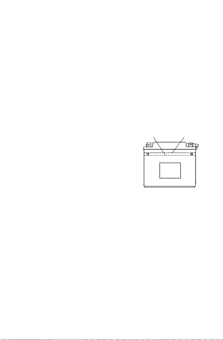
124
MAINTENANCE
Battery
Battery Storage
Whenever the vehicle is not used for a period of three months or more,
remove the battery from the vehicle, ensure that it's fully charged, and
store it out of the sun in a cool, dry place. Check battery voltage each
month during storage and recharge as needed to maintain a full charge.
See page 125.
Tip: Battery charge can be maintained by using a POLARIS Battery Tender
charger or by charging about once a month to make up for normal self-
discharge. Battery Tender can be left connected during the storage period,
and will automatically charge the battery if the voltage drops below a pre-
determined point. See page 134 for the part numbers of POLARIS
products.
Battery Fluid (Conventional Battery)
A poorly maintained battery will
deteriorate rapidly. Check the
battery fluid level often. Maintain
the fluid level between the upper
and lower level marks.
Add only distilled water. Tap water
contains minerals that are harmful
to a battery.
Lower
Mark
Upper
Mark

125
MAINTENANCE
Battery
Battery Charging (Conventional Battery)
1. Remove the battery from the vehicle to prevent damage from
leaking or spilled electrolyte during charging. See page 122.
2. Charge the battery with a charging output no larger than 1/10 of the
battery’s amp/hr rating. Charge as needed to raise the specific
gravity to 1.270 or greater.
3. Reinstall the battery. See page 123. Make sure the positive terminal
is toward the front of the vehicle.
Battery Charging (Sealed Battery)
The following battery charging instructions apply only to the
installation of a sealed battery. Read all instructions before proceeding
with the installation of this battery.
The sealed battery is already filled with electrolyte and has been sealed
and fully charged at the factory. Never pry the sealing strip off or add
any other fluid to this battery.
The single most important thing about maintaining a sealed battery is to
keep it fully charged. Since the battery is sealed and the sealing strip
cannot be removed, you must use a voltmeter or multimeter to measure
DC voltage.
WARNING! An overheated battery may explode, causing severe injury or
death. Always watch charging times carefully. Stop charging if the battery
becomes very warm to the touch. Allow it to cool before resuming charging.
For a refresh charge, follow all instructions carefully.
1. Check the battery voltage with a voltmeter or multimeter. A fully
charged battery will register 12.8 V or higher.
2. If the voltage is less than 12.8 volts, recharge the battery at 1.2 amps
or less until battery voltage is 12.8 or greater.
Tip: When using an automatic charger, refer to the charger manufacturer's
instructions for recharging. When using a constant current charger, use the
guidelines on the next page for recharging.

126
MAINTENANCE
Battery
Battery Charging (Sealed Battery)
Always verify battery condition before and 1-2 hours after the end of
charging.
State of
Charge
Voltage Action
Charge Time
(Using constant current
charger @ standard amps
specified on top of battery)
100% 12.8-13.0 volts None, check at 3
mos. from date of
manufacture
None required
75%-100% 12.5-12.8 volts May need slight
charge, if no
charge given,
check in 3 months
3-6 hours
50%-75% 12.0-12.5 volts Needs charge 5-11 hours
25%-50% 11.5-12.0 volts Needs charge At least 13 hours,
verify state of charge
0%-25% 11.5 volts or less Needs charge with
desulfating charger
At least 20 hours
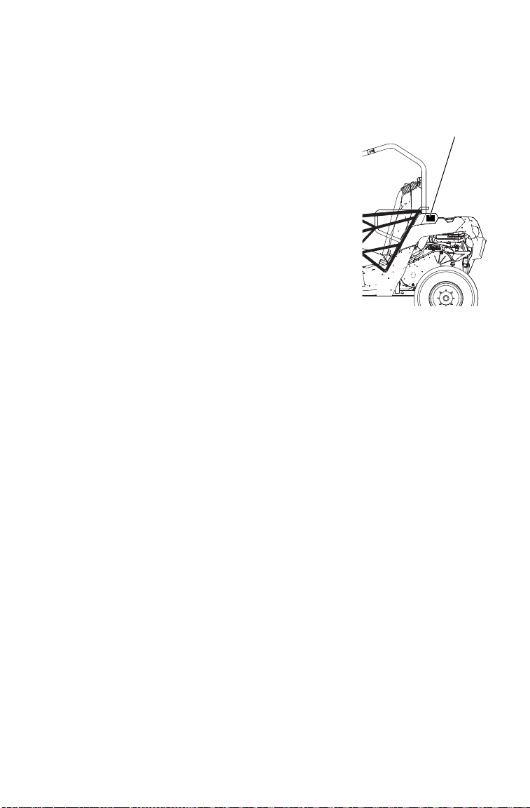
127
MAINTENANCE
Cleaning and Storage
Washing the Vehicle
Keeping your POLARIS vehicle clean will not
only improve its appearance but it can also
extend the life of various components.
NOTICE: Water in the PVT system could cause the
drive belt to become wet and slip in the
clutches. Always avoid spraying water
directly toward any intake pre-filters.
High water pressure may damage the
radiator fins and impair the radiator’s
effectiveness. High pressure may also
damage other vehicle components.
Certain products, including insect repellents
and chemicals, will damage plastic
surfaces. Do not allow these types of
products to contact the vehicle.
The best and safest way to clean your POLARIS vehicle is with a
garden hose and a pail of mild soap and water.
1. Use a professional-type washing cloth, cleaning the upper body first
and the lower parts last.
2. Rinse with clean water frequently.
3. Dry surfaces with a chamois to prevent water spots.
Washing Tips
• Avoid the use of harsh cleaners, which can scratch the finish.
• Do not use a power washer to clean the vehicle.
• Do not use medium to heavy duty compounds on the finish.
• Always use clean cloths and pads for cleaning and polishing. Old or
reused cloths and pads may contain dirt particles that will scratch the
finish.
PVT Intake
Pre-Filter

128
MAINTENANCE
Cleaning and Storage
Washing the Vehicle
If a high pressure water system is used for cleaning (not recommended),
exercise extreme caution. The water may damage components and could
remove paint and labels. Avoid directing the water stream at the
following items:
• Wheel bearings
• Radiator
• Transmission seals
•Brakes
• Cab and body panels
• Labels and decals
• Electrical components and wiring
• Air intake components
If warning and safety labels are damaged, contact your POLARIS dealer
for free replacement.
Grease all zerk fittings immediately after washing. Allow the engine to
run for a while to evaporate any water that may have entered the engine
or exhaust system.
Polishing the Vehicle
POLARIS recommends the use of common household aerosol furniture
polish for polishing the finish on your POLARIS vehicle. Follow the
instructions on the container.
Polishing Tips
• Avoid the use of automotive products, some of which can scratch the
finish of your vehicle.
• Always use clean cloths and pads for cleaning and polishing. Old or
reused cloths and pads may contain dirt particles that will scratch the
finish.

129
MAINTENANCE
Cleaning and Storage
Storage Tips
NOTICE: Starting the engine during the storage period will disturb the
protective film created by fogging and damage could occur. Never
start the engine during the storage period.
Clean the Exterior
Make any necessary repairs and clean the vehicle as recommended. See
page 127.
Stabilize the Fuel
1. Fill the fuel tank.
2. Add POLARIS Carbon Clean Fuel Treatment or POLARIS Fuel
Stabilizer. Follow the instructions on the container for the
recommended amount. Carbon Clean removes water from fuel
systems, stabilizes fuel and removes carbon deposits from pistons,
rings, valves and exhaust systems.
3. Allow the engine to run for 15-20 minutes to allow the stabilizer to
disperse through the entire fuel delivery system.
Oil and Filter
Change the oil and filter. See page 93.
Air Filter / Air Box
Inspect and clean or replace the pre-filter and air filter. Clean the air
box. See pages 108-109.
Fluid Levels
Inspect the fluid levels. Add or change fluids as recommended in the
Periodic Maintenance Chart beginning on page 85.
• Demand drive fluid (front gearcase)
• Rear gearcase fluid (if equipped)
• Transmission fluid
• Brake fluid (change every two years and any time the fluid looks dark
or contaminated)
• Coolant (test strength/fill)

130
MAINTENANCE
Cleaning and Storage
Storage Tips
Inspect and Lubricate
Inspect all cables and lubricate all areas of the vehicle as recommended
in the Periodic Maintenance Chart beginning on page 85.
Fog the Engine
1. Treat the fuel system with POLARIS Carbon Clean. Follow the
instructions on the container. Start the engine. Allow it to idle for
several minutes so the Carbon Clean reaches the injectors. Stop the
engine.
2. Remove the spark plug and add 2-3 tablespoons of engine oil. To
access the plug holes, use a section of clear 1/4” hose and a small
plastic squeeze bottle filled with the pre-measured amount of oil.
Do this carefully! If you miss the plug holes, oil will drain from the
spark plug cavities into the hole at the front of the cylinder head,
and appear to be an oil leak.
3. Reinstall the spark plug. Torque to specification. See page 99.
4. Apply dielectric grease to the inside of each spark plug cap. Do not
reinstall the cap onto the plug at this step.
5. Turn the engine over several times. Oil will be forced in and around
the piston rings and ring lands, coating the cylinder with a
protective film of fresh oil.
6. If POLARIS fuel system additive is not used, fuel tank, fuel lines,
and injectors should be completely drained of gasoline.
7. Reinstall the spark plug cap to the spark plug.
Battery Maintenance
See pages 124-126 for storage and charging procedures.
Storage Area/Covers
Be sure the storage area is well ventilated. Cover the vehicle with a
genuine POLARIS cover. Do not use plastic or coated materials. They
do not allow enough ventilation to prevent condensation, and may
promote corrosion and oxidation.

131
MAINTENANCE
Cleaning and Storage
Removal from Storage
1. Check the battery electrolyte level and charge the battery if
necessary. Install it in the vehicle. Make sure the battery vent hose is
routed properly and that it's not pinched or restricted in any way.
2. Make sure the spark plug is tight.
3. Fill the fuel tank with fuel.
4. Check all the points listed in the Daily Pre-Ride Inspection section
on page 54. Tightness of the bolts, nuts and other fasteners should
be checked by an authorized POLARIS dealer.
5. Lubricate at the intervals outlined in the Periodic Maintenance
Chart beginning on page 85.
WARNING! Engine exhaust contains poisonous carbon monoxide and can
cause loss of consciousness or death. Never run an engine in an enclosed area.
Transporting the Vehicle
Follow these procedures when transporting the vehicle.
1. Place the transmission in PARK. Stop the engine.
2. Remove the key to prevent loss during transporting.
3. Secure the fuel cap and seat. Ensure that the seat is attached
correctly and is not loose.
WARNING! Cargo and other loose vehicle parts may fly off while transporting
this vehicle. Secure or remove all cargo, and inspect the unit for loose parts prior
to transport.
4. Always tie the frame of the POLARIS vehicle to the transporting
unit securely with suitable straps or rope. Do not attach tie straps to
the front control arm bolt pockets.

132
SPECIFICATIONS
ACE 570
Gross Vehicle Weight 660 kg
Dry Weight 392.4 kg (+/- 5%)
Test GVW - Rollover Protection
System (ROPS)
682.7 kg per OSHA 29 CFR 1928.53
Front Rack/Box Capacity 55 kg
Rear Rack/Box Capacity 110 kg
Maximum Weight Capacity
(Payload)
261 kg (operator/cargo/accessories/trailer tongue
weight)
Receiver Hitch Tongue Capacity 68 kg
Receiver Hitch Towing Capacity 680 kg
Fuel Capacity 19.9 l
Engine Oil Capacity 1.9 l
Coolant System Capacity 2.8 l excluding coolant bottle
Coolant Bottle Capacity 237 ml
Demand Drive Fluid Capacity 265 ml
Transmission Oil Capacity 1300 ml
Overall Length/Width/Height 228.6/122/173 cm
Wheelbase 156.2 cm
Ground Clearance 26 cm
Engine Dual overhead cam, 4 valve 4 stroke single
cylinder
Displacement 567 cc
Bore x Stroke 99 mm x 73.6 mm
Alternator Output 650 W @ 7000 RPM
Compression Ratio 10:1
Starting System Electric
Fuel System Electronic fuel injection
Throttle Body Size 36 mm
Ignition System Digital CDI
Ignition Timing 10° +/- 1° @ 1200 RPM (non-adjustable)
Spark Plug / Gap NGK MR7F / 0.8 +/- 0.1 mm
Front Suspension MacPherson strut with 20.8 cm travel
Rear Suspension Dual A-arm, anti-sway bar with 24.1 cm travel

133
SPECIFICATIONS
Clutching
ACE 570
Lubrication System Wet Sump
Engine Oil PS-4 5W-50
Driving System Type Automatic POLARIS Variable Transmission
Shift Type Side Lever (H/L/N/R/P)
Gear Reduction - Low 28.84:1
Gear Reduction - Reverse 25.83:1
Gear Reduction - High 9.65:1
Drive Ratio - Front 2.989:1
Tire Size - Front 25x8-12
Tire Size - Rear 25x10-12
Tire Pressure 45 kPa
Brakes, Park Park in Transmission
Brakes, Front/Rear Foot Activated, 4-wheel hydraulic disc
Headlights 2 single beam, 55W halogen
Turn Signal Standard
Hazard Signals Standard
Horn Standard
Mirrors Standard
Taillights 2 single beam, 6W
Brake Lights 2 single beam, 27W
Instrument Cluster LCD
Auxiliary DC Outlet 12V
Altitude Shift
Weight
Drive Clutch
Spring
Driven Clutch
Spring
Meters
(Feet)
0-1500
(0-5000)
25-52
PN 5632409
Black 35-240
PN 7043594
Black/Almond
PN 3235088
1500-3700
(5000-12000)
25-48
PN 5632408
Black 35-240
PN 7043594
Black/Almond
PN 3235088

134
POLARIS PRODUCTS
Part
Number
Description
Engine Lubricant
2870791 Fogging Oil (12 oz./355 ml Aerosol)
2876244 PS-4 Full Synthetic 5W-50 4-Cycle Oil (qt./.95 l)
2876245 PS-4 Full Synthetic 5W-50 4-Cycle Oil (gal./3.8 l)
Gearcase / Transmission Lubricants
2878068 AGL Full Synthetic Gearcase Lubricant & Transmission Fluid
(qt./.95 l)
2878069 AGL Full Synthetic Gearcase Lubricant & Transmission Fluid
(gal./3.8 l)
2870465 Pump for Gallon (3.8 l) Jug
2877922 Demand Drive Fluid (qt./.95 l)
2877923 Demand Drive Fluid (gal./3.8 l)
Coolant
2880514 Antifreeze 50/50 Premix (qt./.95 l)
2880513 Antifreeze 50/50 Premix (gal./3.8 l)
Grease / Specialized Lubricants
2871312 Grease Gun Kit, Premium All Season
2871322 All Season Grease (3 oz./89 ml cartridge)
2871423 All Season Grease (14 oz./414 ml cartridge)
2871460 Premium Starter Grease
2871515 U-Joint Grease (3 oz./89 ml cartridge)
2871551 U-Joint Grease (14 oz./414 ml cartridge)
2871329 Dielectric Grease (Nyogel™)
Additives / Miscellaneous
2871326 Carbon Clean
2870652 Fuel Stabilizer
2872189 DOT 4 Brake Fluid
2871956 Loctite™ 565 Thread Sealant
2859044 POLARIS Battery Tender™ Charger

135
TROUBLESHOOTING
Drive Belt Wear/Burn
Possible Cause Solution
Driving onto a pickup or
tall trailer in high range
Use low range during loading.
Starting out going up a
steep incline
Use low range. See warnings on page 62.
Driving at low RPM or
ground speed (3-7 MPH)
Drive at a higher speed or use low range more frequently.
Insufficient warm-up at
low ambient
temperatures
Warm the engine at least 5 minutes. With the transmission
in neutral, advance the throttle to about 1/8 throttle in
short bursts, 5 to 7 times. The belt will become more flex-
ible and prevent belt burning.
Slow/easy clutch
engagement
Use the throttle quickly and effectively.
Towing/pushing at low
RPM/low ground speed
Use low range only.
Utility use/plowing Use low range only.
Stuck in mud or snow Shift the transmission to low range and carefully use fast,
aggressive throttle application to engage clutch.
WARNING: Excessive throttle may cause loss of control
and vehicle rollover.
Climbing over large
objects from a stopped
position
Shift the transmission to low range and carefully use fast,
brief, aggressive throttle application to engage clutch.
WARNING: Excessive throttle may cause loss of control
and vehicle rollover.
Belt slippage from water
or snow ingestion into the
PVT system
Dry out the PVT (see page 107). Prevent water from
entering the PVT intake duct (see page 109). Inspect
clutch seals for damage if repeated leaking occurs.
Clutch malfunction See your POLARIS dealer.
Poor engine performance Check for fouled plug or foreign material in gas tank or
fuel lines. See your POLARIS dealer.
Slippage from failure to
warm up belt
Always warm up the belt by operating below 30 mph for
one mile (5 miles or more when temperature is below
freezing).
Wrong or missing belt Install the recommended belt.
Improper break-in Always break in a new belt and/or clutch. See page 52.

136
TROUBLESHOOTING
Engine Doesn't Turn Over
Engine Turns Over, Fails to Start
Engine Backfires
Possible Cause Solution
Low battery voltage Recharge the battery to 12.8 VDC
Loose battery connections Check all connections and tighten
Loose solenoid connections Check all connections and tighten
Loose electronic control box connections Inspect, clean, reinstall connectors
Possible Cause Solution
Out of fuel Refuel
Clogged fuel filter See your POLARIS dealer
Water is present in fuel Drain the fuel system and refuel
Old or non-recommended fuel Replace with fresh recommended fuel
Fouled or defective spark plug Inspect plug and replace if necessary
No spark to spark plug Inspect plug and replace if necessary
Water or fuel in crankcase Immediately see your POLARIS dealer
Low battery voltage Recharge the battery to 12.8 VDC
Mechanical failure See your POLARIS dealer
Possible Cause Solution
Weak spark from spark plug Inspect, clean and/or replace spark plug
Incorrect spark plug gap or heat range Set gap to specs or replace plug
Old or non-recommended fuel Replace with fresh recommended fuel
Incorrectly installed spark plug wires See your POLARIS dealer
Incorrect ignition timing See your POLARIS dealer
Mechanical failure See your POLARIS dealer
Loose ignition connections Check all connections and tighten
Water present in fuel Replace with fresh recommended fuel

137
TROUBLESHOOTING
Engine Pings or Knocks
Engine Runs Irregularly, Stalls or Misfires
Possible Cause Solution
Poor quality or low octane fuel Replace with recommended fuel
Incorrect ignition timing See your POLARIS dealer
Incorrect spark plug gap or heat range Set gap to specs or replace plug
Possible Cause Solution
Fouled or defective spark plug Inspect, clean and/or replace spark plug
Worn or defective spark plug wires See your POLARIS dealer
Incorrect spark plug gap or heat range Set gap to specs or replace plug
Loose ignition connections Check all connections and tighten
Water present in fuel Replace with new fuel
Low battery voltage Recharge battery to 12.8 VDC
Kinked or plugged fuel tank vent line Inspect and replace
Incorrect fuel Replace with recommended fuel
Clogged air filter Inspect and clean or replace
Low fuel pressure See your POLARIS dealer
Other mechanical failure See your POLARIS dealer
Possible Lean Fuel Cause Solution
Low or contaminated fuel Add or change fuel, clean the fuel system
Low octane fuel Replace with recommended fuel
Clogged fuel filter See your POLARIS dealer
Possible Rich Fuel Cause Solution
Fuel is very high octane Replace with lower octane fuel

138
TROUBLESHOOTING
Engine Stops or Loses Power
Possible Cause Solution
Out of fuel Refuel
Kinked or plugged fuel vent line Inspect and replace
Water is present in fuel Replace with new fuel
Fouled or defective spark plug Inspect, clean and/or replace spark plug
Worn or defective spark plug wires See your POLARIS dealer
Incorrect spark plug gap or heat range Set gap to specs or replace plug
Loose ignition connections Check all connections and tighten
Low battery voltage Recharge the battery to 12.8 VDC
Incorrect fuel Replace with fresh recommended fuel
Clogged air filter Inspect and clean or replace
Other mechanical failure See your POLARIS dealer
Overheated engine Clean radiator screen and core, clean
engine exterior, see your POLARIS
dealer

139
WARRANTY
LIMITED WARRANTY
POLARIS Industries Inc., 2100 Highway 55, Medina, MN 55340 (POLARIS) gives a
TWO YEAR LIMITED WARRANTY on all components of your POLARIS vehicle
against defects in material or workmanship. POLARIS further warrants that the spark
arrester in this product will meet the efficiency requirements of USFS standard 5100-1C
for at least 1000 hours when subjected to normal use and when maintenance and
installation are in accordance with POLARIS recommendations.
This warranty covers parts and labor charges for repair or replacement of defective parts
and begins on the date of purchase by the original retail purchaser. This warranty is
transferable to another owner during the warranty period through a POLARIS dealer,
but any such transfer will not extend the original term of the warranty. The duration of
this warranty may vary by international region based upon local laws and regulations.
Registration
At the time of sale, the Warranty Registration Form must be completed by your dealer
and submitted to POLARIS within ten days of purchase. Upon receipt of this
registration, POLARIS will record the registration for warranty. No verification of
registration will be sent to the purchaser as the copy of the Warranty Registration Form
will be your proof of warranty coverage. If you have not signed the original registration
and received the customer copy, please contact your dealer immediately. NO
WARRANTY COVERAGE WILL BE ALLOWED UNLESS YOUR VEHICLE IS
REGISTERED WITH POLARIS. Initial dealer preparation and set-up of your vehicle is
very important in ensuring trouble-free operation. Purchasing a machine in the crate or
without proper dealer set-up will void your warranty coverage.
Warranty Coverage And Exclusions:
Limitations Of Warranties And Remedies
This POLARIS limited warranty excludes any failures that are not caused by a defect in
material or workmanship. THIS WARRANTY DOES NOT COVER CLAIMS OF
DEFECTIVE DESIGN. This warranty also does not cover acts of God, accidental
damage, normal wear and tear, abuse or improper handling. This warranty also does not
cover any vehicle, component, or part that has been altered structurally, modified,
neglected, improperly maintained or used for racing, competition or purposes other than
for which it was designed.
This warranty excludes damages or failures resulting from improper lubrication;
improper engine timing; improper fuel; surface imperfections caused by external stress,
heat, cold or contamination; operator error or abuse; improper component alignment,
tension, adjustment or altitude compensation; snow, water, dirt or other foreign
substance ingestion/contamination; improper maintenance; modified components; use
of aftermarket or unapproved components, accessories, or attachments; unauthorized
repairs; or repairs made after the warranty period expires or by an unauthorized repair
center.

140
WARRANTY
Warranty Coverage And Exclusions:
Limitations Of Warranties And Remedies
This warranty excludes damages or failures caused by abuse, accident, fire, or any other
cause other than a defect in materials or workmanship and provides no coverage for
consumable components, general wear items, or any parts exposed to friction surfaces,
stresses, environmental conditions and/or contamination for which they were not
designed or not intended, including but not limited to the following items:
Lubricants and Fluids
1. Mixing oil brands or using non-recommended oil may cause engine damage. We
recommend the use of POLARIS engine oil.
2. Damage or failure resulting from the use of non-recommended lubricants or fluids is
not covered by this warranty.
This warranty provides no coverage for personal loss or expense, including mileage,
transportation costs, hotels, meals, shipping or handling fees, product pick-up or
delivery, replacement rentals, loss of product use, loss of profits, or loss of vacation or
personal time.
• Wheels and tires • Finished and unfinished surfaces
• Suspension components • Carburetor/Throttle body components
• Brake components • Engine components
• Seat components • Drive belts
• Clutches and components • Hydraulic components and fluids
• Steering components • Circuit breakers/Fuses
• Batteries • Electronic components
• Light bulbs/Sealed beam lamps • Spark plugs
•Filters •Sealants
• Lubricants • Coolants
• Bushings • Bearings

141
WARRANTY
Warranty Coverage And Exclusions:
Limitations Of Warranties And Remedies
THE EXCLUSIVE REMEDY FOR BREACH OF THIS WARRANTY SHALL BE, AT
POLARIS' OPTION, REPAIR OR REPLACEMENT OF ANY DEFECTIVE
MATERIALS, COMPONENTS, OR PRODUCTS. THE REMEDIES SET FORTH IN
THIS WARRANTY ARE THE ONLY REMEDIES AVAILABLE TO ANY PERSON
FOR BREACH OF THIS WARRANTY. POLARIS SHALL HAVE NO LIABILITY
TO ANY PERSON FOR INCIDENTAL, CONSEQUENTIAL OR SPECIAL
DAMAGES OF ANY DESCRIPTION, WHETHER ARISING OUT OF EXPRESS OR
IMPLIED WARRANTY OR ANY OTHER CONTRACT, NEGLIGENCE, OR
OTHER TORT OR OTHERWISE. THIS EXCLUSION OF CONSEQUENTIAL,
INCIDENTAL, AND SPECIAL DAMAGES IS INDEPENDENT FROM AND SHALL
SURVIVE ANY FINDING THAT THE EXCLUSIVE REMEDY FAILED OF ITS
ESSENTIAL PURPOSE.
THE IMPLIED WARRANTY OF FITNESS FOR A PARTICULAR PURPOSE IS
EXCLUDED FROM THIS LIMITED WARRANTY. ALL OTHER IMPLIED
WARRANTIES (INCLUDING BUT NOT LIMITED TO THE IMPLIED
WARRANTY OF MERCHANTABILITY) ARE LIMITED IN DURATION TO THE
ABOVE TWO YEAR WARRANTY PERIOD. POLARIS DISCLAIMS ALL
EXPRESS WARRANTIES NOT STATED IN THIS WARRANTY. SOME STATES DO
NOT PERMIT THE EXCLUSION OR LIMITATION OF INCIDENTAL OR
CONSEQUENTIAL DAMAGES OR ALLOW LIMITATIONS ON THE DURATION
OF IMPLIED WARRANTIES, SO THE ABOVE LIMITATIONS MAY NOT APPLY
TO YOU IF INCONSISTENT WITH CONTROLLING STATE LAW.

142
WARRANTY
How To Obtain Warranty Service
If your vehicle requires warranty service, you must take it to a POLARIS Servicing
Dealer. When requesting warranty service you must present your copy of the Warranty
Registration Form to the dealer. (THE COST OF TRANSPORTATION TO AND
FROM THE DEALER IS YOUR RESPONSIBILITY.) POLARIS suggests that you use
your original selling dealer; however, you may use any POLARIS Servicing Dealer to
perform warranty service.
In the Country where your product was purchased:
Warranty or Service Bulletin repairs must be done by an authorized POLARIS dealer. If
you move or are traveling within the country where your product was purchased,
Warranty and Service Bulletin repairs may be requested from any authorized POLARIS
dealer that sells the same line as your product.
Outside the Country where your product was purchased:
If you are traveling temporarily outside the country where your product was purchased,
you should take your product to an authorized POLARIS dealer. You must show the
dealer photo identification from the country of the selling dealer's authorized location as
proof of residence. Upon residence verification, the servicing dealer will be authorized
to perform the warranty repair.
If you move:
If you move to another country, be sure to contact POLARIS Customer Assistance and
the customs department of the destination country before you move. Product
importation rules vary considerably from country to country. You may be required to
present documentation of your move to POLARIS in order to continue your warranty
coverage. You may also be required to obtain documentation from POLARIS in order to
register your product in your new country. You should warranty register your product at
a local POLARIS dealer in your new country immediately after you move to continue
your warranty coverage and to ensure that you receive information and notices regarding
your vehicle.
If you purchase from a private party:
If you purchase a POLARIS product from a private party, to be kept and used outside of
the country in which the product was originally purchased, all warranty coverage will be
denied. You must nonetheless register your product under your name and address with a
local POLARIS dealer in your country to ensure that you receive safety information and
notices regarding your product.

143
WARRANTY
Exported Products
EXCEPT WHERE SPECIFICALLY REQUIRED BY LAW, THERE IS NO WAR-
RANTY OR SERVICE BULLETIN COVERAGE ON THIS PRODUCT IF IT IS
SOLD OUTSIDE THE COUNTRY OF THE SELLING DEALER'S AUTHORIZED
LOCATION. This policy does not apply to products that have received authorization for
export from POLARIS. Dealers may not give authorization for export. You should con-
sult an authorized dealer to determine this product's warranty or service coverage if you
have any questions. This policy does not apply to products registered to government
officials or military personnel on assignment outside the country of the selling dealer's
authorized location. This policy does not apply to Safety Bulletins.
Notice
If your product is registered outside of the country where it was purchased and you have
not followed the procedure set above, your product will no longer be eligible for
warranty or service bulletin coverage of any kind, other than safety bulletins. Products
registered to government officials or military personnel on assignment outside of the
country where the product was purchased will continue to be covered by the Limited
Warranty.
Please work with your dealer to resolve any warranty issues. Should your dealer require
any additional assistance, they will contact the appropriate person at POLARIS.
This warranty gives you specific legal rights, and you may also have other rights which
vary from state to state or in different countries. If any of the above terms are void
because of federal, state, local law, all other warranty terms will remain in effect.

144
MAINTENANCE LOG
Use the following chart to record periodic maintenance.
DATE MILES (KM)
OR HOURS
TECHNICIAN SERVICE PERFORMED / COMMENTS

145
INDEX
A
Access Panels 25
Accessory Outlet 33
Adjustment
Seat 29
Steering Wheel 26
Age Restrictions 14
Air Filter 108
Air Filter Cleaning 108
All Wheel Drive 71, 72
All Wheel Drive (AWD)
Disengaging AWD 72
Engaging AWD 71
Locking the Differential 71
All Wheel Drive Switch 33
Arrester Cleaning 110
Auxiliary Outlet 33
AWD 71, 72
AWD Switch 33
Axle Nut Torque 115
B
Battery 121, 122, 123, 124, 125, 126
Charging (Conventional) 125
Charging (Sealed) 125, 126
Extreme Use 28
Fluid (Conventional) 124
Installation 123
Removal 122
Storage 124
Battery Fluid, Adding (Conventional)
124
Before Riding 54
Belt Burning 135
Belt Life 69
Belt Replacement 106
Belt Wear 135
Belt, Seat 30
Boots 11
Box Cover, Front 27
Brake Fluid 112
Brake Inspection 113
Brake Lever, Park 36
Brake Light Lamp Replacement 117
Brake Lights 117
Brake Pedal 35
Brake System Break-in 53
Brakes 111, 112, 113
Braking 57
Break-In Period 52, 53
Breather Hose Inspection 109
Bumper Removal 25
Burning Belts 135
C
Cab Frame, ROPS 37
Cab Nets 28
Cap, Fuel 29
Cargo 68, 69
Chart, Periodic Maintenance 85, 86, 87,
88
Check Engine Indicator 45
Cleaning and Storage 127, 128, 129,
130, 131
Clothing 11
Component Locations 24
Coolant Level 104
Coolant Level, Radiator 103
Coolant, Adding or Changing 102
Cooling Fan 103
Cooling System 103, 104
Cooling System Operation 102
Cover for Storage 130
D
Declaration of Conformity 7
Demand Drive Fluid 95, 96
Diagnostic Codes 50, 51
Diagnostic Display Code Definitions 46,
47, 48, 49, 50, 51
Differential Locking 71
Disengaging AWD 72
Display Units, Standard/Metric 42
Drive Belt Wear 135
Drivetrain Break-In 53
Driving After Driving in Water 107
Driving Downhill 64
Driving in Reverse 67
Driving on a Sidehill 63
Driving on Slippery Surfaces 61
Driving Over Obstacles 66
Driving Procedures 58, 59
Driving Through Water 65
Driving Uphill 62

146
INDEX
E
Electromagnetic Interference 84
Emission Control, Exhaust 84
Emission Control, Noise 84
Engaging AWD 71
Engine Break-In 53
Engine Fogging 130
Engine Intake Pre-Filter 109
Engine Oil 91, 92, 93, 94
Engine Starting 56
Engine Stopping 57
Equipment Modifications 23
Error Codes, Engine 45
Exhaust Emission Control System 84
Exhaust Pipe Cleaning 110
Extreme Use Battery 28
Eye Protection 11
F
Fan, Cooling 103
Filter Care During Storage 129
Filter Cleaning, Air 108
Filter, Air 108
Fluid
Demand Drive 95, 96
Front Gearcase 95, 96
Main Gearcase 97
Transmission 97
Fluid Change
Demand Drive 96
Front Gearcase 96
Main Gearcase 97
Transmission 97
Fluid Check
Coolant Bottle 104
Demand Drive 95
Front Gearcase 95
Main Gearcase 97
Radiator Coolant 103
Transmission 97
Fluid Levels During Storage 129
Fluid Recommendations, Gearcase 98
Fluid, Brake 112
Fogging the Engine 130
Freeplay, Steering Wheel 114
Front Box Cover 27
Front Gearcase Fluid 95, 96
Fuel Cap 29
Fuel Safety 22
Fuel Stabilizer 129
Fuel Tank Filler Cap 29
Fuses 100, 101
G
Gasoline Handling 22
Gear Selector 34
Gear Shifter 34
Gearcase Capacities 98
Gearcases 95, 96, 97, 98
Demand Drive Unit 95, 96
Front Gearcase 95, 96
Main Gearcase 97
Specification Chart 98
Transmission 97
Gloves 11
H
Hauling a Load 68, 69
Hauling Cargo 68, 69
Hazard Switch 33
Headlight Beam Adjustment 119
Headlight Lamp 118
Helmet 10
High Beam Switch 31
Hitch 25
Hitch Weight 70
Horn Switch 31
I
Ignition Switch 32
Inspection
Pre-Ride 54
Seat Belt 30
Instrument Cluster 38, 39, 40, 41, 42, 43,
44, 45, 46, 47, 48, 49, 50, 51
Interference, Electromagnetic 84
K
Key, Periodic Maintenance Chart 86
L
LED Headlamps 117
Light Switch 32
Lights 117, 118, 119
Beam Adjustment 119
Brake Lights 117
Front Turn Signal Replacement 118
Headlight Lamp 118
LED Headlamps 117
Position Light Lamp 118
Taillight/Brake Light 117
Turn Signal Lamp, Rear 117
Loads, Towing 70
Lubrication for Storage 130
Lubrication Recommendations 89, 90

147
INDEX
M
Maintenance Log 144
Maintenance, Periodic 85, 86, 87, 88
Metric Display 42
Mirrors 27
Mode Button 38
Muffler Cleaning 110
N
Nets, Cab 28
New Operator Driving Procedures 58, 59
Noise Emission Control System 84
O
Obstacles 66
Oil
Demand Drive 95, 96
Engine 92, 93, 94
Engine Oil 91
Front Gearcase 95, 96
Main Gearcase 97
Transmission 97
Oil and Filter Care During Storage 129
Oil Change
Demand Drive 96
Engine 93, 94
Front Gearcase 96
Main Gearcase 97
Transmission 97
Oil Check
Demand Drive 95
Engine Oil 92
Front Gearcase 95
Main Gearcase 97
Transmission 97
Oil Recommendations 91
Operator Restrictions 14
P
Park Brake Lever 36
Parking on an Incline 67
Parking the Vehicle 57
Periodic Maintenance Chart 85, 86, 87,
88
Plug, Accessory 33
Polishing the Vehicle 128
Position Light Lamp 118
Pre-Filters, Intake 109
Pre-Ride Inspection 54
PVT Break-In 53
PVT Drying 107
PVT Intake Pre-Filter 109
PVT System Operation 105, 106, 107
PVT, Cleaning Debris 106
R
Radiator 103
Radiator Access 25
Radiator Coolant Level 103
Receiver Hitch 25
Refueling Safety 22
Registration, Warranty 139
Removal, Seat 29
Removing the Vehicle from Storage 131
Restrictions, Age 14
Reverse 67
Rider Information Center 40, 41, 42, 43,
44, 45
Riding Gear 10, 11
Rollover Protective Structure 37
ROPS Cab Frame 37

148
INDEX
S
Safe Operation Practices 55
Safety Labels 12, 13
Safety Symbols 4
Safety Training 9
Safety Warnings 14, 15, 16, 17, 18, 19,
20, 21, 22, 23
Safety, Winch Maintenance 83
Seat Adjustment 29
Seat Belt 30
Seat Removal 29
Service Panels 25
Severe Use Definition 85
Shifting Gears 34
Shock Loading the Winch 82
Signal Words 4
Spark Arrester 84
Spark Arrester, Cleaning 110
Spark Plug 98, 99
Spark Plug Condition 99
Spark Plug Gap 98
Spark Plug Removal 99
Spark Plug Torque 98
Specifications, Gearcase 98
Speed, Towing 70
Speedometer 38
Spring Adjustment, Rear Shock 114
Stabilizing the Fuel 129
Starting the Engine 56
Steering Lock 26
Steering Wheel Adjustment 26
Steering Wheel Inspection 114
Stopping the Engine 57
Storage 127, 128, 129, 130, 131
Storage and Inspection 130
Storage and Lubrication 130
Storage Area 130
Storage, Covers 130
Storage, Fluid Levels 129
Storage, Oil and Filter 129
Storage, Removal 131
Switches 31, 32, 33
AWD Switch 33
Hazard Switch 33
High Beam Switch 31
Horn Switch 31
Ignition Switch 32
Light Switch 32
Mode Button Switch 38
Turn Signal Lever 31
T
Tachometer 43
Taillight Lamp Replacement 117
Throttle Pedal 35
Tire Tread Depth 115
Tires 115, 116
Towing Loads 70
Towing Speed 70
Trailer Hitch 25
Training 9
Transmission Drying 107
Transmission Oil 97
Transmission Operation 105, 106, 107
Transporting the Vehicle 131
Turn Signal Lamp, Rear 117
Turn Signal Lever 31
Turning the Vehicle 60
V
Vehicle Identification Numbers 8
Vehicle Immersion 120
Vehicle Transport 131
W
Warning Symbols 4
Washing the Vehicle 127, 128
Water, Immersion of Vehicle 120
Wear, Drive Belt 135
Weight, Hitch 70
Wheel Installation 116
Wheel Nut Torque 115
Wheel Removal 116
Winch Cable Care 81
Winch Maintenance and Service Safety
83
Winch Operation 76, 77, 78, 79, 80
Winch Safety Precautions 73, 74, 75
Winch Shock Loading 82


For your nearest Polaris dealer,
visit www.polaris.com
Polaris Sales Europe Sarl
Route de l’Etraz
Business Center A5
1180 Rolle, Switzerland
Part No. 9927489 Rev 02
PMS 419