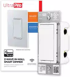
• May be used in single-pole installation or with up to four add-on switches (model 39350) in 3-way or 4-way wiring configurations
• Compatible with all incandescent and most dimmable CFL/LED bulbs
• Auto line/load detection
• Blue LED indicates dimmer location in a dark room
• Screw terminal installation — requires wiring connections for line (hot), load, neutral and ground. Traveler wire required for 3-way or 4-way installation
• This Z-Wave device has advanced features that allow you to customize your experience.
A. Ground (Green/Bare)
B. Line or Load (Black)
C. Line or Load (Black)
D. Traveler (Red/Other)
E. Neutral (White)
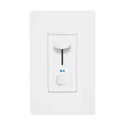
E. Top rocker — press & release to turn dimmer ON, press & hold to increase brightness
F. Bottom rocker — press & release to turn dimmer OFF, press & hold to dim
2. INSTALLATION
WARNING — SHOCK HAZARD
Turn OFF the power to the branch circuit for the dimmer and lighting fixture at the service panel. All wiring connections must be made with the POWER OFF to avoid personal injury and/or damage to the dimmer. This device is intended for installation in accordance with the National Electric Code and local regulations in the United States or the Canadian Electrical Code and local regulations in Canada. If you are unsure or uncomfortable about performing this installation, consult a qualified electrician.
MULTI-SWITCH WIRING
Add-on switch model 39350 is required for multi-switch installations. For more information on multi-switch installations, refer to the add-on switch manual.
SINGLE-SWITCH WIRING
1. Shut off power to the circuit at circuit breaker or fuse box.
IMPORTANT! Verify power is OFF to switch box before continuing.
2. Remove wallplate.
3. Remove the switch mounting screws.
4. Carefully remove the switch from the switch box. DO NOT disconnect the wires.
5. There are up to five screw terminals on the dimmer; these are marked:
A. GROUND — Green/Bare
B. LINE OR LOAD — Black (connected to power or lighting)
C. LINE OR LOAD — Black (connected to power or lighting)
D. TRAVELER — Red/Other (only in 3-way installations)
E. NEUTRAL — White
Match these screw terminals to the wires connected to the existing switch.
6. Disconnect the wires from the existing switch. Label wires according to the previous terminal connection.
OBSERVE IMPORTANT WIRING INFORMATION
IMPORTANT! This dimmer is rated for and intended to only be used with copper wire.
WIRE GAUGE REQUIREMENTS
Use 14AWG or larger wires suitable for at least 80° C for supplying line (hot), load, neutral, ground and traveler connections.
WIRE STRIP LENGTH
7. For attachment using the enclosure’s holes, strip insulation 5/8in. (16mm). Do not wrap wires around screws. UL specifies the tightening torque for the screws is 14Kgf-cm (12lbf-in).
8. Connect the green or bare copper ground wire to the GROUND terminal (A).
9. Connect the black wire from the light to either LINE/LOAD terminal (B).
10. Connect the black wire from the electrical service panel (hot) to the other LINE/LOAD terminal (C).
11. Connect the white wire to the neutral terminal (E) (use a jumper wire if needed).
12. Insert dimmer into the switch box being careful not to pinch or crush wires.
13. Mount the wallplate.
14. Reapply power to the circuit at fuse box or circuit breaker and test the system.
MANUAL CONTROL
The front panel rocker dimmer allows the user to turn ON/OFF the connected fixture.
1. To turn the connected fixture ON, press and release the top of the rocker.
2. To turn the connected fixture OFF, press and release the bottom of the rocker.
ADJUST DIM LEVELS
1. To increase brightness, press and hold the top of the rocker.
2. To decrease brightness, press and hold the bottom of the rocker.
CYCLE LED LIGHT
The LED below the dimmer acts as a guide light or status indicator.
How to cycle through options: Press up three times and down once quickly.
1. LED is ON when the load is OFF (guide light in the dark) (default).
2. LED is ON when the load is ON (indicates the dimmer is ON).
3. LED is always OFF.
4. LED is always ON (illuminates dimmer in the dark).
3. CONNECTION
CONNECTING TO A Z-WAVE NETWORK
1. Follow the instructions for your Z-Wave certified controller to add a device to the Z-Wave network.
2. Once the controller is ready to add your device, press and release the top or bottom of the smart dimmer (rocker).
If prompted by the controller to enter the S2 security code, refer to the QR code/security number on the back of the box or the QR code label on the product.
REMOVING AND RESETTING THE DEVICE
1. Follow the instructions for your Z-Wave certified controller to remove a device from the Z-Wave network.
2. Once the controller is ready to remove your device, press and release the top or bottom of the smart dimmer (rocker).
RETURNING DIMMER TO FACTORY DEFAULTS
Quickly press ON (top) button three times, then, immediately press the OFF (bottom) button three times. The LED will flash ON/OFF five times when completed successfully.
NOTE: This should only be used in the event your network’s primary controller is missing or otherwise inoperable.
NOTE: SmartStart enabled products can be added into a Z-Wave network by scanning the QR code on the product with a controller providing SmartStart inclusion. No further action is required and the SmartStart product will be added automatically within 10 minutes of being switched on in the network vicinity.
OPTIONAL CUSTOMIZATION
CHANGING THE COLOR OF THE PADDLE
1. Lift the air gap tab at the base of the paddle.
2. Push side tabs in on one side and then the other to release paddle. Lift the cover up and off.
3. Simply put the new paddle onto the dimmer by inserting the air gap and side tabs and snapping securely into place.