Owner Manual Miter Saw
Getting To Know Your Miter Saw
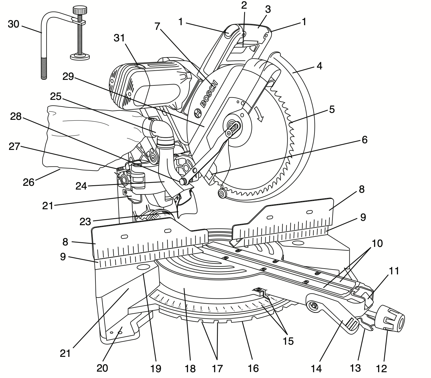
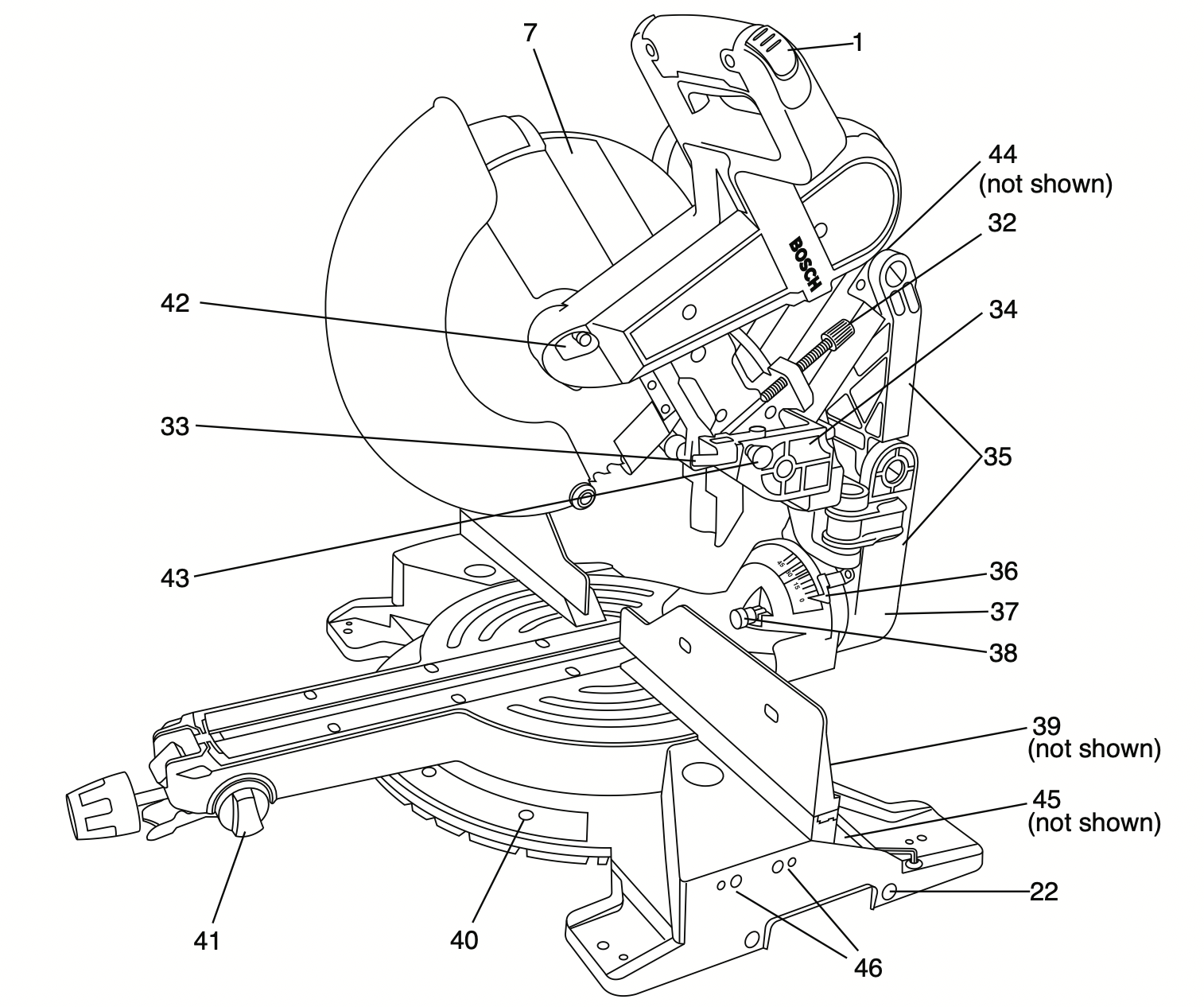
WARNING: To avoid injury from accidental starting, remove plug from power source outlet before making any adjustments.
- Switch lock-Off Release Buttons – One of these two buttons must be pressed before the power switch can be pressed.
- Power Switch – The power switch used with the “Lock-OFF” button energizes the unit.
- Main Handle – This handle contains the power switch. Pulling this handle down lowers the blade into the workpiece.
- Lower Blade Guard/lower Guard lip – The lower blade guard helps protect your hands from the spinning blade. It retracts as the blade is lowered. Lip can be used to raise the lower guard in the event that the guard becomes jammed on a workpiece.
- Blade – Use only 10” (254 mm) diameter blades with 5/8” (16 mm) diameter arbor holes.
- Chip Deflector – Deflects cut-off workpieces from entering the upper guard.
- Upper Guard – Covers upper portion of the blade.
- Sliding fence – Supports the workpiece. The fence has a cast-in scale to make repetitive cuts easy. The fence also has holes to secure an auxiliary fence if desired.
- Stationary fence – Stationary fence is bolted to the base and will support the workpiece when the sliding fence is removed.
- Kerf Inserts – Kerf inserts can be adjusted to different blade widths to minimize workpiece tear-out.
- Miter Detent Override – Allows detent action to be locked out, allowing for micro-adjustments to any miter angle.
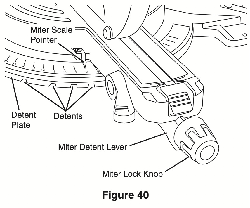
- Miter lock Knob – The miter lock knob locks the miter saw table at any desired miter angle.
- Miter Detent lever – The lever releases the table from the detent.
- Bevel lock lever – The front-positioned bevel lock lever locks the head assembly at the desired bevel angle.
- Miter Scale/Miter pointer – The pointer rotates with the table and blade. It points to the miter scale to indicate the angle setting before a cut is made.
- Miter Detent plate – The position of the plate can be adjusted to set the accuracy of its detent locations.
- Miter Detents – There are ten (10) miter detent slots for fast and accurate miter cuts of common miter angles.
- Table – Sits in base, provides workpiece support, rotates for desired miter cuts and rotates the head assembly. The front extended part of the table is called the miter arm.
- Base – Provides working surface to support workpiece.
- Tool Mounting pads – The four corners of the saw provide areas to clamp, bolt or nail the saw to a flat work surface.
- Chop/Crown lock – Locks head assembly at intervals for maximum capacity chop cuts in up right material and crown molding.
- Holes for Optional Sliding Base Extensions – For attaching optional sliding base extension. Provides extra work support. Useful when cutting long workpieces.
- Rubber Deflector – Attaches to bottom of chute. Deflects dust into the chute.
- Dust Chute – Directs sawdust up and through the elbow and to the bag.
- Elbow – Connects the dust chute to the dust bag.
- Dust Bag – Has a zipper at the bottom. Bag can be uncoupled from elbow for emptying.
- Mechanism lock lever – Holds saw in full back position for chop cuts or fully extended for transporting.
- Link Knob – Attaches guard link to the pivot post.
- Lower Guard link – Allows for smooth movement of the lower guard.
- Clamp – Use to hold the workpiece to the table and base – insert into clamp post location (item 39).
- Brush Cap – Keeps motor brushes in position. Provides access for inspecting and replacing brushes.
- Depth Stop Screw – Turn the knob end to adjust the blade depth for cutting grooves.
- Depth Stop plate – Plate can be swung out to limit the depth of the blade travel.
- Pivot post – Provides support for the saw head, dust collection system and other functional parts.
- Axial Glide Mechanism – Allows saw to smoothly slide in and out. Can be locked in full rear or fully extended positions.
- Bevel Scale and pointers – Scale is large and angled - allows user to easily read bevel angles. Pointer indicates what the current angle is.
- Bevel post – Provides rotating support for all miter saw parts above the table.
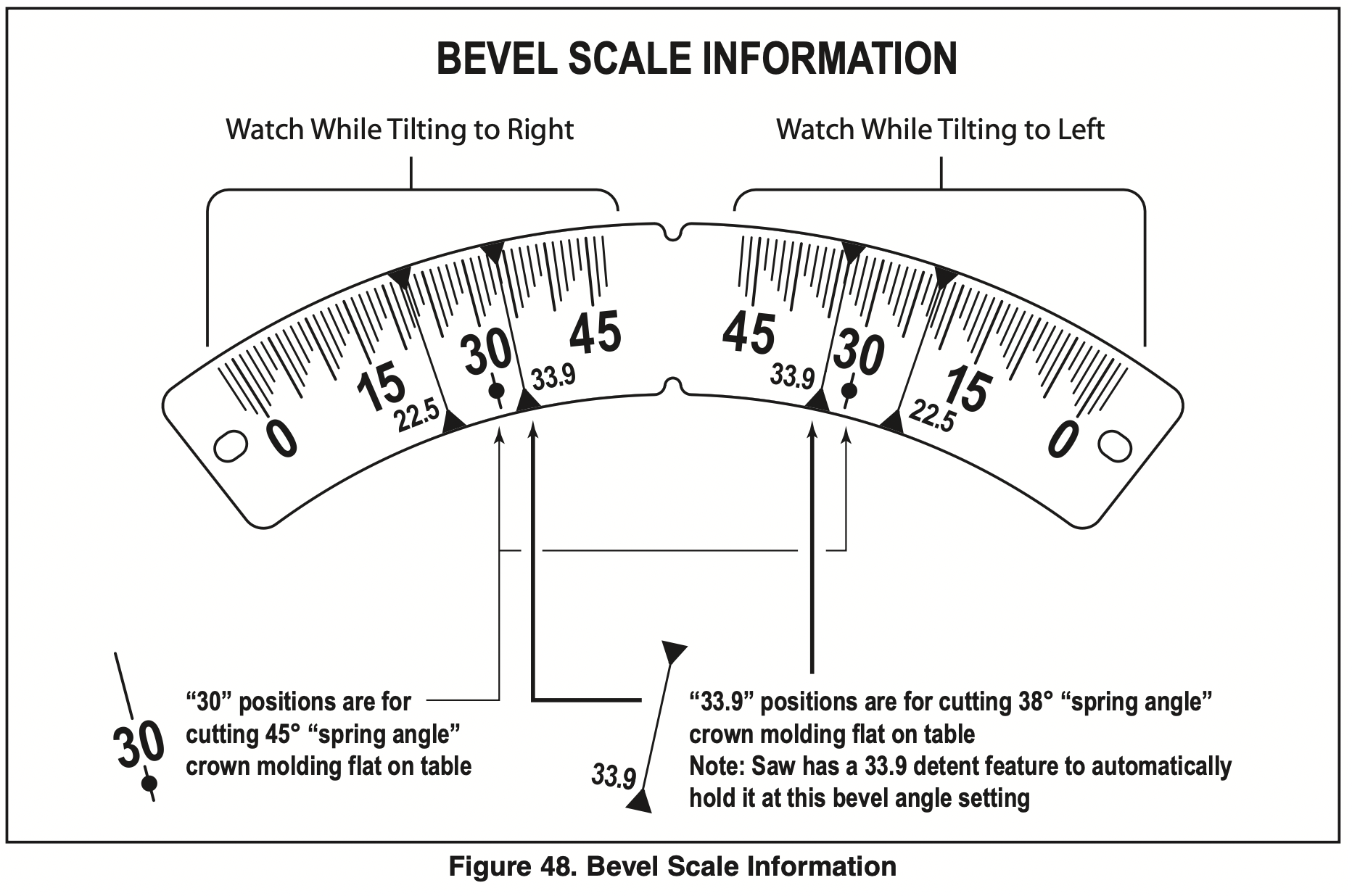
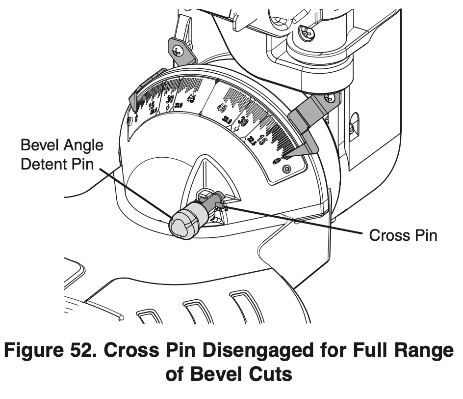
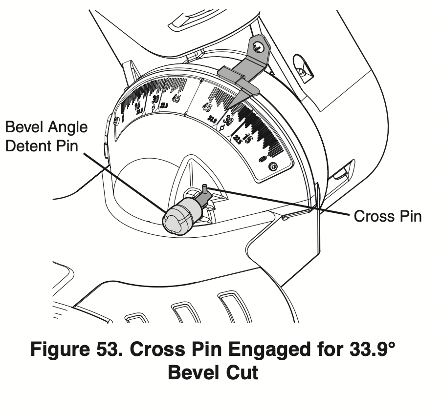
- Bevel Detent pin (Crown Molding Setting) – When engaged, it locks the head assembly to the bevel angle of 33.9° to the left or right.
- Clamp post locations – Two vertical post holes in the base – provided to insert the clamp (item 30).
- Miter Detent plate Screws – Four screws accessible through holes in the miter scale. These screws are loosened when adjusting position of the detent plate.
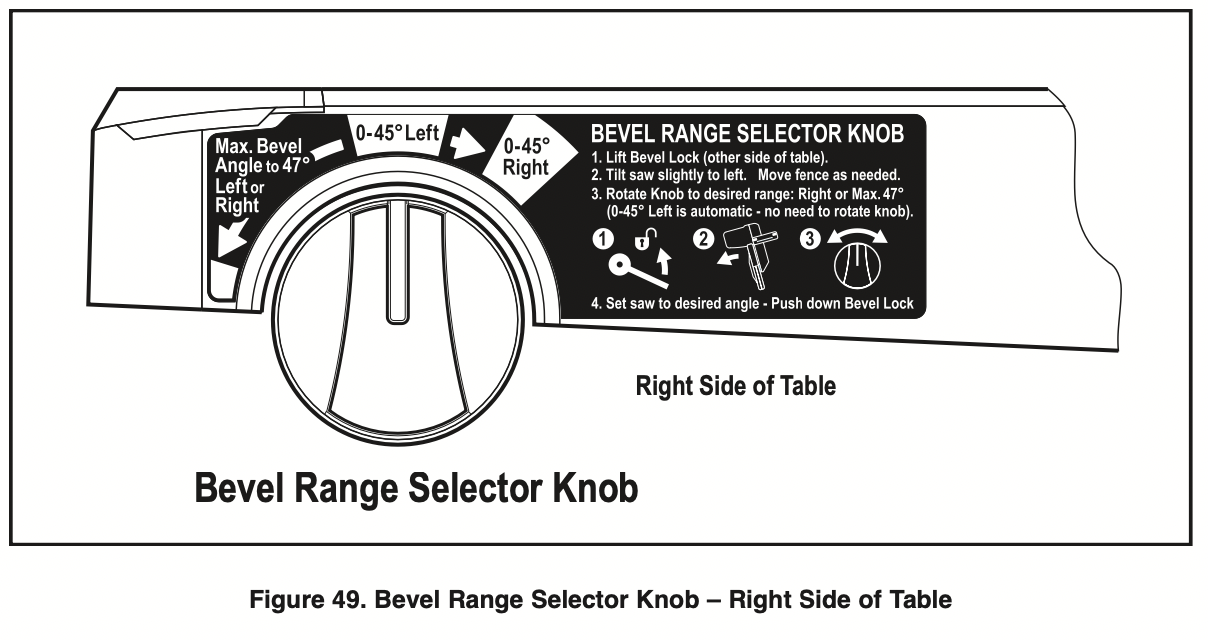
- Bevel Range Selector Knob – Allows selection of 3 bevel ranges: “0-45° Left”, “0-45° Right” or “Max. Bevel Angle to 47°.”
- Arbor lock – Press arbor lock button to keep blade from rotating when loosening or tightening arbor bolt during blade removal or installation.
- Head Assembly lock pin – Used to lock the head assembly in the lower position for transporting.
- Glide Movement Controller – Adjusts to regulate movement of the glide mechanism.
- Base Extension Clamping Knobs – Locks the optional the base extensions (not included) at the desired positions.
- Crown stop mount holes – For attaching optional crown stop supports, see page 55.
Preparing for Saw Operations
Body and Hand position
WARNING: Properly position to your make body cutting and hands easier and safer. failure to follow all instructions, identified below by bullet (l) symbols, may result in serious personal injury (see figure 30).
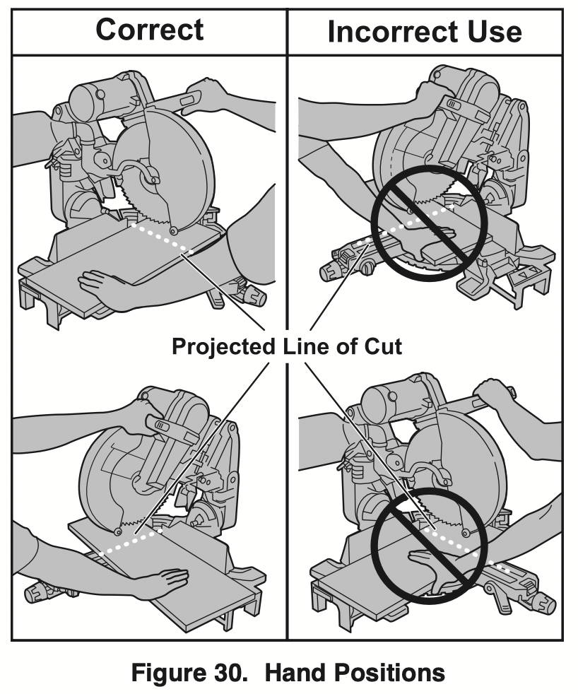
- Never place hands near cutting area. Keep hands and arms outside the “NO HANDS” zone.
“NO HANDS” ZONE – is defined as the entire table and on the right and left side of the table and portions of the fence within this boundry. This zone is labeled with “No Hands” symbols placed on the fixed base.
- Be aware of the path of the saw blade. Make a DRY RUN with the saw “Off” by conducting a simulated cutting cycle, and observe the projected path of the saw blade. Keep hands out of the path of saw blade.
DRY RUN – It is important to know where the blade will intersect with the workpiece during cutting operations. Always perform the simulated cutting sequence with the power tool switched “OFF” to gain an understanding of the projected path of the saw blade. Mentally note where the path of the saw blade will fall and set up your work to keep your hands and arms out of the path of the spinning blade. Adjust your clamps and fences so that the smooth lower guard and cutting action is not interfered with during cutting operation (see Figure 30).
Hold workpiece firmly against table and fence to prevent movement.
- Keep hands in position until trigger has been released and blade has completely stopped.
- Never place hands on mechanism components.
- Keep feet firmly on the floor and maintain proper balance.
- Follow the miter arm when mitering left or right. Stand slightly to the side of the saw blade.
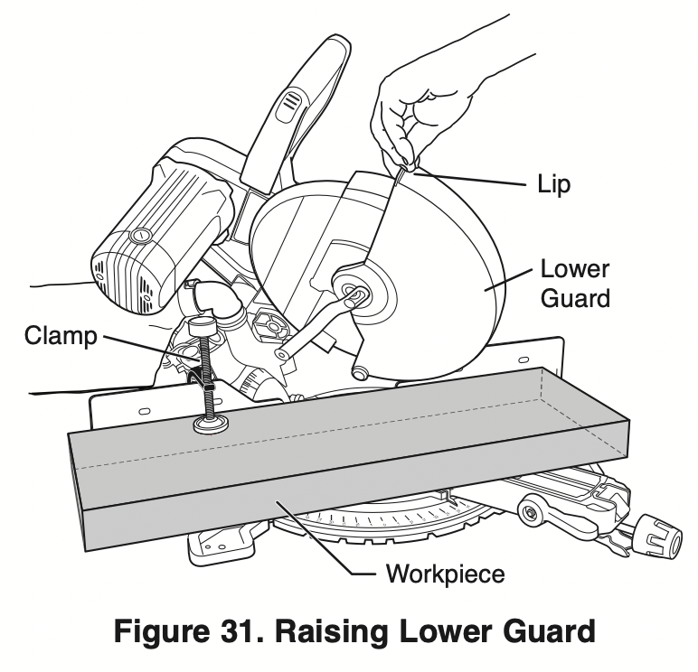
WARNING: The lower guard may not automatically open under certain cutting conditions; for example, when trying to cut workpieces that are near the maximum cutting height capacity. Under these conditions or during the blade travel motion of cut, the workpiece can stop the lower guard movement before the downward motion of the arm could pre-open the lower guard.
If this occurs:
Workpiece must be securely clamped. This frees a hand to raise the guard by the lip just enough to clear the workpiece (see Figure 31).
Start the saw and begin your cut.
Once you have cleared the position where the lower guard may bind, release the guard and it will continue to operate automatically as you cut.
Workpiece Support
Clamps
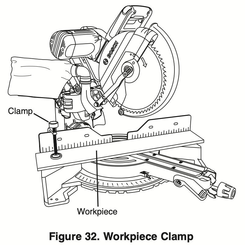
Using the Workpiece Clamp – This clamp easily secures a workpiece to the table or base.
- Insert the clamp’s knurled bar down into a clamp post hole; there are two post holes located in the base behind the fence. The knurled end must be in the post at least 1/2".
- Slide the clamp down until its rubber foot contacts the workpiece.
- Adjust the clamp height so it does not touch the sliding fence.
- Rotate the clamp’s knob until the workpiece is firmly held in place.
- Move saw head up and down and forward and back to be sure it clears the clamp.
WARNING: There may be extreme compound cuts where clamp cannot be used. Support workpiece with your hand outside the “No Hands” zone. Do not try to cut short pieces that cannot be clamped and cause your hand to be in the “No Hands” zone.
Clamps – Other hold-down devices such as Cclamps can be used to hold the workpiece firmly against the table and the fence. Make sure the clamps are clear of the cutting path.
Sliding fences
WARNING: To provide sufficient (minimum saw 6") spacing from hand to blade, extend the sliding fences and base extensions when making extreme bevel, miter or compound cuts.
Operating Sliding fences
- Loosen the fence lock knob by turning counterclockwise.
- Slide the fence to the desired position.
- Lock fence in desired position by turning lock knob clockwise.
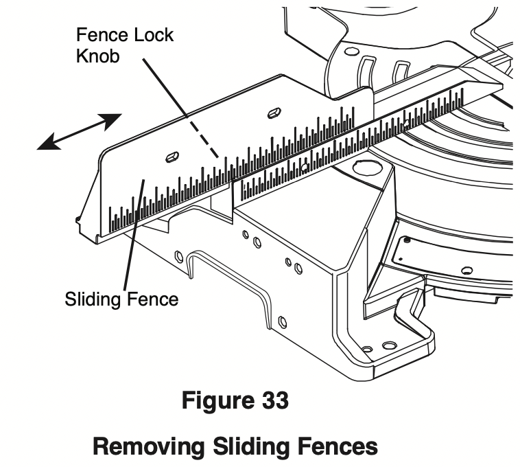
Removing Sliding fences
When performing compound cuts, miter cutting at extreme bevel angles the fence may need to be removed.
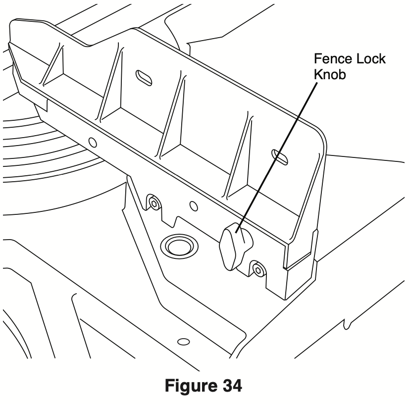
- Rotate the fence lock knob counter clockwise seven rotations.
- Lift up on fence to remove.
Workpiece Support
Long Workpiece Support
WARNING: Long workpieces have a tendency to tip over unless clamped down and properly supported from underneath.
Additional Workpiece Support
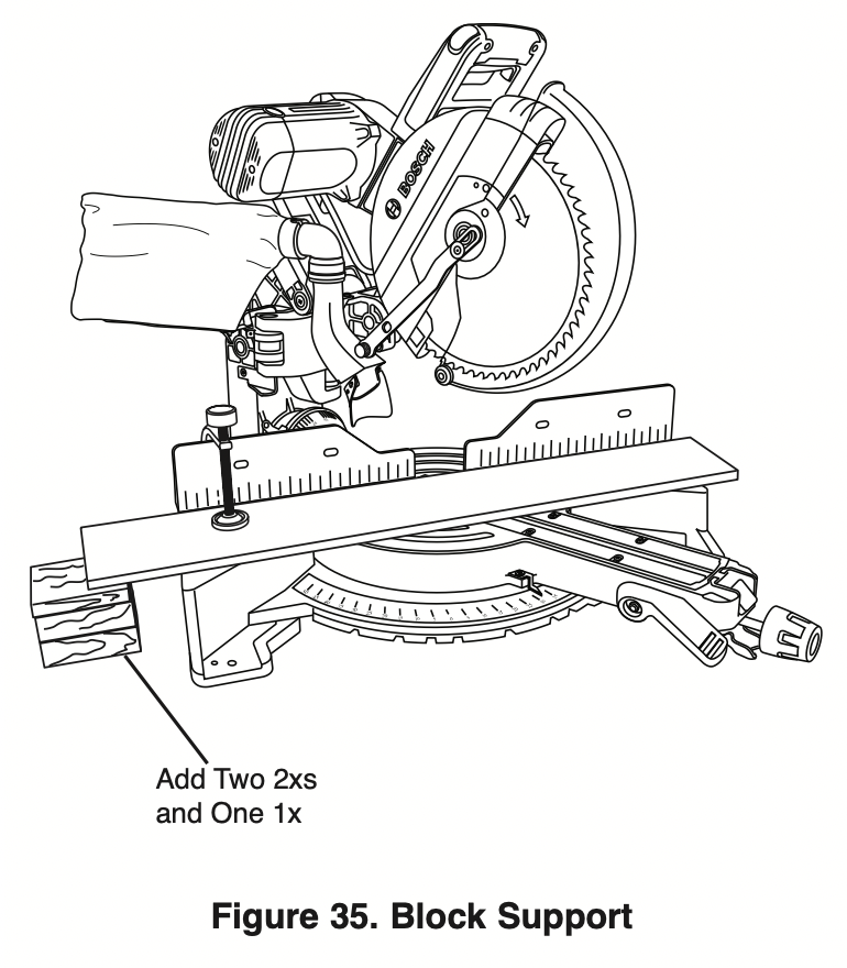
Blocks – Long pieces need extra support. The base height (3-3/4") is designed to match the standard lumber of two 2xs and one 1x. Boards of these thicknesses can be used to create auxiliary support extensions for long workpieces (see Figure 35).
Making an Auxiliary fence
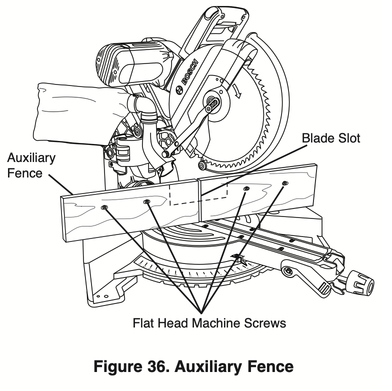
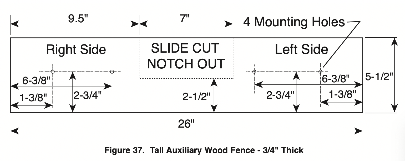
Certain types of molding need a fence face extension because of the size and position of the workpiece. Holes are provided in the fence to attach an auxiliary fence. The auxiliary fence is used with the saw in the 0° bevel position only.
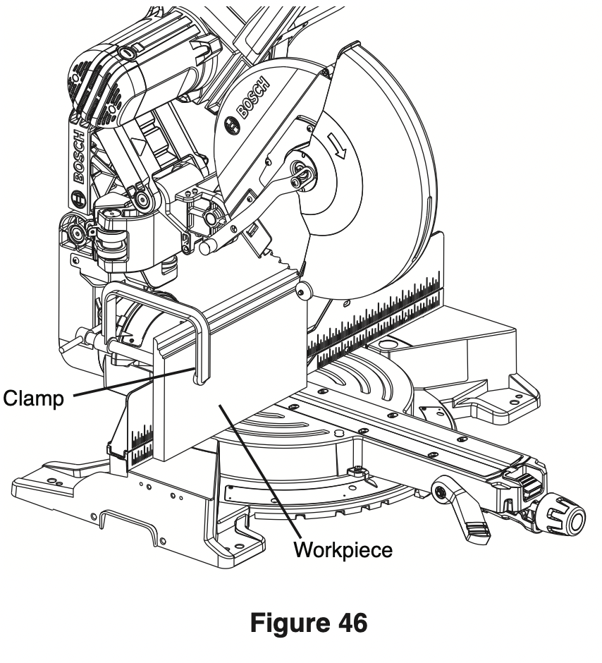
- Place a piece of wood against the miter saw fence (see Figure 36). Wood can have a maximum height of 5-1/2". Check that auxiliary fence assembly does not interfere with head assembly. See dimension drawing – Figure 37.
- Mark the locations of the support holes on the wood from the back side of the fence.
- Drill and countersink the holes on the front of the support board.
- Fasten from front of fence: Attach (each) auxiliary fence using two (2) 3/16" flat head machine screws. With 3/4" auxiliary fence, use 1-1/2" long screws. Secure behind metal fence with washer and machine nuts.
Fasten from back of fence: With 3/4" auxiliary fence, use 1/4" round head wood screws (3/4" long). Drill four pilot holes through auxiliary fence and run screws from rear of metal fence.
- Make a full depth cut to create the blade slot. Check for interference between the auxiliary fence and the lower blade guard. Make adjustments as necessary.
- For best splinter-free cuts, use the chop cut method.
- When making slide cuts, the center must be notched out per pattern (see Figure 37).
WARNING: Check for interference from any components.
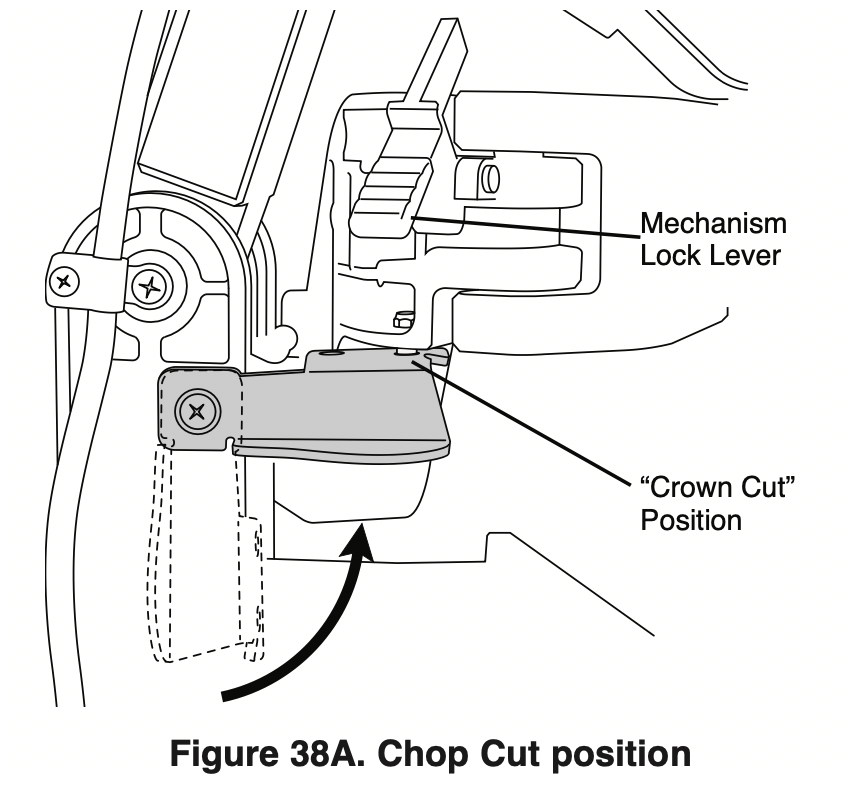
Chop/Crown lock
This saw is equipped with a Chop/Crown Lock feature that is intended to lock the head assembly in place while giving the maximum capacity for upright cuts and crown cuts.
Engaging head for traditional Chopcuts
- To engage the Chop/Crown feature ensure that the mechanism lock lever is disengaged.
- Slide the head assembly forward and engage the lever into the first hole labeled “Chop Cut”.
The saw is capable of making upright cuts against the fence up to 5-1/4” tall.
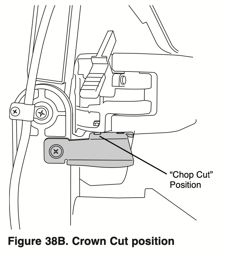
Engaging head for Crown Molding
- To engage the Chop/Crown feature ensure that the mechanism lock lever is disengaged.
- Slide the head assembly forward and engage the lever into the second hole labeled “Crown Cut”.
The saw is capable of cutting crown molding (for crown cutting refer to pages 45-49).
Saw Operations
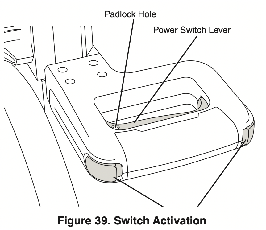
Switch Activation
For safety, the switch lever is designed to prevent accidental starts. To operate safety switch, press the switch “Lock-OFF” button with either thumb to disengage the lock, then pull the power switch lever and release the switch “Lock-OFF” release button (see Figure 39). When the power switch lever is released, the switch “Lock-OFF” button will engage the safety switch automatically, and the lever will no longer operate until either “Lock-OFF” button is pressed again.
NOTE: The power switch lever is made with a hole to accommodate a long shackle padlock to prevent unauthorized use of the saw (padlock is not provided with tool). The lock’s shackle diameter may be up to 1/4".
Using Miter Detent System
- Loosen the miter lock knob about 1/2 turn.
- Grip the lock knob, and then reach down with your index finger to pull up on the miter detent lever pull lever until it is out from the detent plate.
- While gripping the lock knob and lever, rotate the saw’s table. Stop table rotation at the desired angle as indicated by the miter scale pointer.
- Release the lever into a detent in the detent plate or at an angle between detents. If close to a detent, use the detent override feature.
- Tighten the miter lock knob before cutting.
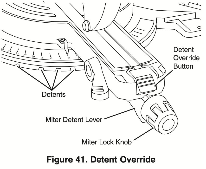
Miter Detent Override
The miter detent override system locks out the automatic detent action. When the desired miter angle is close to a standard detent slot, this feature will hold the detent lever wedge from engagement (i.e., the user wants to be at 44-1/2°, but detent wedge wants to pop into the 45° detent). When the detent override is used, the detent system is disabled and the table will move smoothly to any position within its range.
Engaging the Miter Detent Override
- Pull up and hold the miter detent lever – the lever is located under the turntable’s front arm (see Figure 41).
- Press down on the top half of the detent override button and then release hold of the detent lever. The override button will remain in the DOWN position (see Figure 41).
- The turntable is free to rotate.
WARNING: With the table free to rotate, the miter lock knob must be tightened before attempting any cutting.
Disengaging the Miter Detent Override
- Pull up the miter detent lever and the detent override system will automatically disengage. The override button will return to the UP position.
- Loosen the miter lock knob to allow the table to rotate to a new position – the detent lever is now free to engage the preset detent slots.
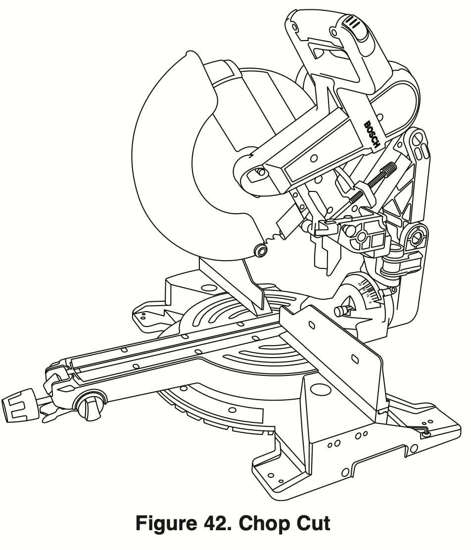
Chop Cuts
What’s a Chop Cut – Saw features
- A “chop cut” is a cross-cut made when the saw is held to the rearmost position and is operated like a conventional (non-sliding) miter saw. Using the chop cut method lowers the cross-cutting capacity; however, many users prefer using this method because it is quicker when making repeat cuts. This method can also produce more accurate cuts because the saw head is locked in the retracted position.
- This saw has bevel angle stops that accurately stop at critical angles:0°R45°Left/Rightand ight. It comes factory-set and should not require adjustment. However, after extensive use or if the tool has received a hard impact, it may require an adjustment.
- A chop cut can cut pieces with a width of 5-1/2" or less
Preparing for Chop Cut
- With the saw head in the UP position, push it back over the fence to the rear.
- Engage the mechanism lock lever (item 27 – page 9) by lifting up the finger tab. Check that mechanism movement is stopped.
- Properly position your workpiece and clamp it firmly to the table and/or fence.
WARNING: Use clamping position that does not interfere with operation. Before switching “ON,” lower head assembly to make sure clamp clears guard and head assembly.
Making a Chop Cut
- Activate the switch, then fully lower the saw head to make the cut.
- Hold the saw head down until the blade comes to a complete stop. Return the saw head to the UP position. Remove workpiece.
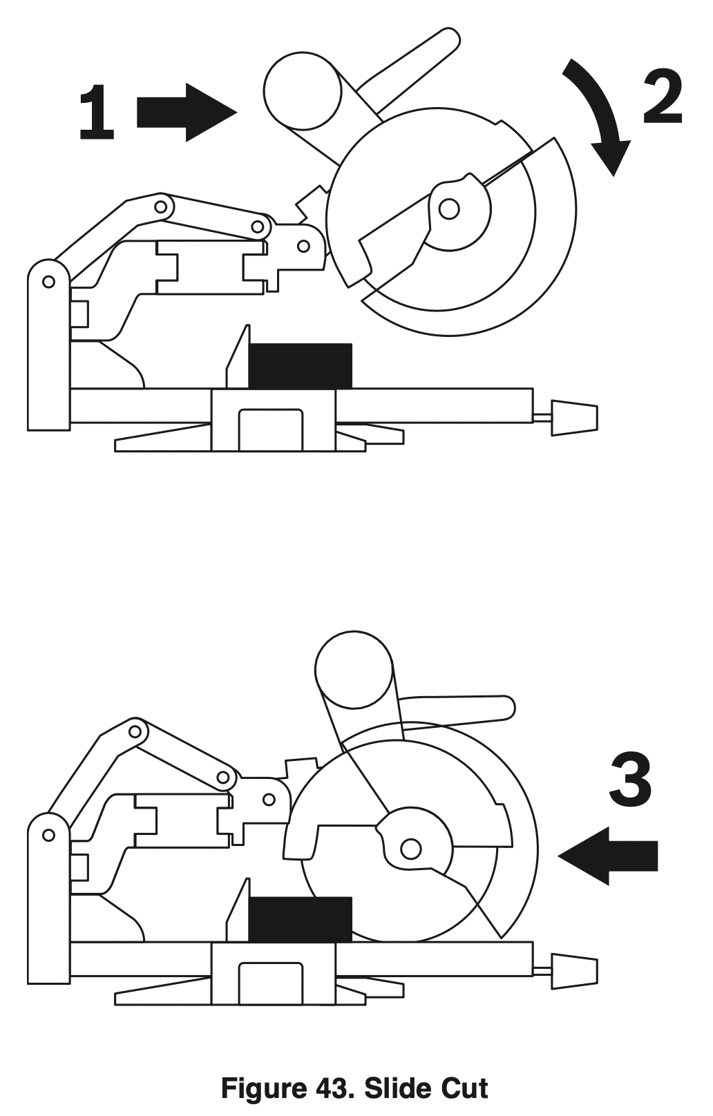
Slide Cuts
What’s a Slide Cut – Saw features
- A “slide cut” is made with the head assembly unlocked and able to move away from the fence. This movement is supported and precisely controlled by the axial glide system. The maximum cross-cutting capacity is utilized by using this method.
- A slide cut is best used for cross-cutting workpieces wider than can be done with a chop cut – pieces wider than 5-1/4" and up to a maximum width of 12-1/2" across.
WARNING: NEVER pull the saw toward you during a cut. The blade can suddenly climb up on top of the workpiece and force itself toward you.
Preparing for Slide Cut
- Place the saw head in the UP position.
- Disengage the mechanism lock lever (item 27 page 9) by pushing down on the finger tab. With the head assembly in the UP position, move it fully to the front and back to check that axial glide system moves smoothly.
- Properly position your workpiece and clamp it firmly to the table and/or fence.
WARNING: Use a clamping position that does not interfere with operation. Before switching “ON,” lower head assembly to make sure clamp clears guard and head assembly.
Making a Slide Cut
- Grasp the switch handle and pull the saw head assembly (in UP position) away from the fence see Arrow 1 in Figure 43.
- Activate the switch, and then fully lower the saw head assembly – on larger pieces, this action may also start the cut – see Arrow 2 in Figure 43.
- Push down and back so the saw head assembly moves toward the fence and to the full rear position until you complete the cut. See Arrow 3 in Figure 43.
NOTE: If high resistance is felt, do not apply excessive force – stop cutting, wait until blade stops and investigate problem.
- Hold the saw head down until the blade comes to a complete stop. Return the saw head to the UP position and remove the workpiece.
Miter Cuts
What’s a Miter Cut – Saw features
- A “miter cut” is a cross-cut made with the blade perpendicular to the horizontal table. The blade is not tilted and the bevel0°lpointersarebothonthe ines.
- Miter cuts can be made at any angle across a workpiece within this saw’s range, from 52° left to 60° right.
- The miter scale shows the angle of the blade relative to the saw’s fence. The miter pointer is attached to the turntable and indicates the saw’s miter position before the cut is made.
- Ten positive detents are provided for fast and accurate preset miter angles – locations are at 45°, 31.6°, 22.5°, 15° left and right, and center at 0°. The right side has an additional detent of 60°.
- The crown molding detents on the left and right are at 31.6° for compound cutting 38° “spring angle” crown molding lying flat on the table (see Cutting Crown Molding on page 45).
- For precision settings at miter angles very close to the miter detents, use the miter detent override to prevent the detent from automatically engaging the detent slot. See detent override instructions on page 33.
- A miter cut can be made either as a chop cut or slide cut, depending on the width of the workpiece.
- The kerf inserts should be adjusted to be as close to the blade as possible to reduce splintering (see kerf insert instructions on page 20).
Reading the Miter Scale
The miter scale used on this saw includes several scales of information to help the user accurately preset this saw before making the cuts (see Figure 44).
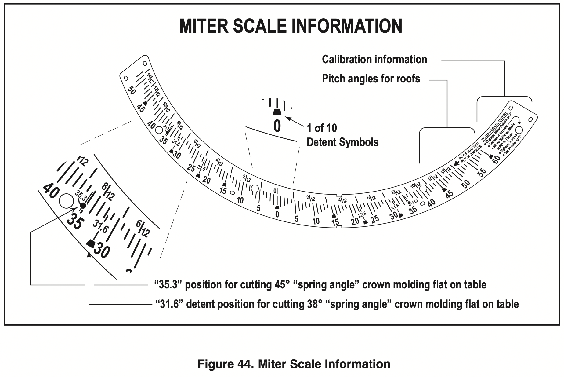
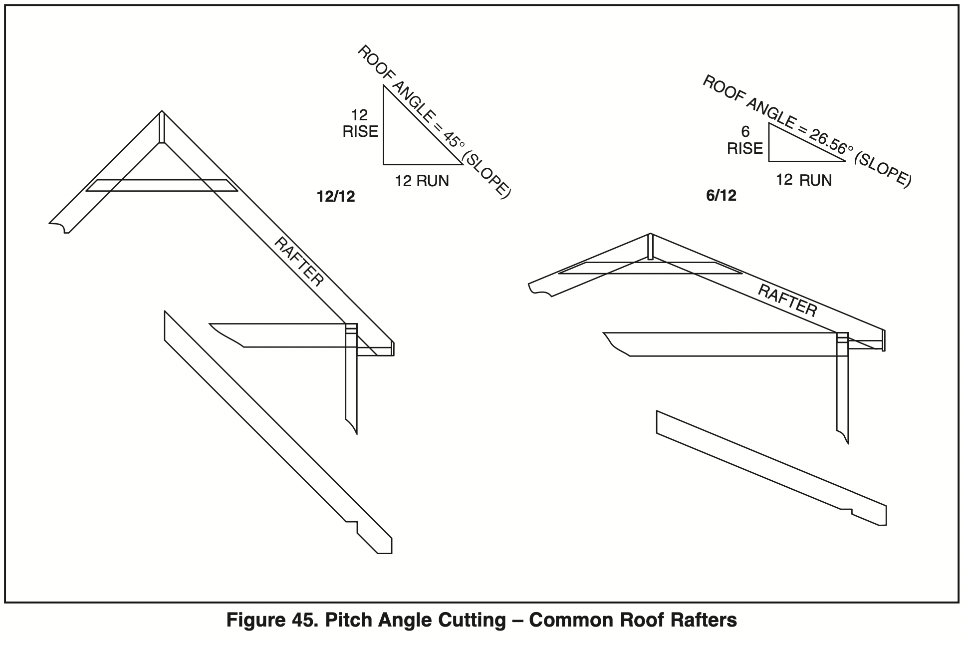
Pitch angle information – The top section of the miter scale shows angle settings required to cut roof rafters to the “Pitch Angle” system. 2/2, 4/12, 6/12, etc., are all pitch angles. This system is based on using the English “inches.” A 6/12 pitch angle roof equals a ratio of 6" “rise” for every 12" “run” (see Figure 45).
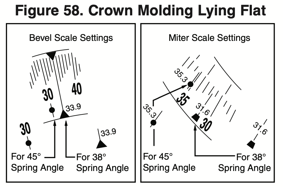
Crown molding information – There are miter position settings for compound-cutting crown molding flat on the table. Crown molding with 38° “spring angle” uses the 31.6 setting (with detent) and crown molding with 45° “spring angle” uses the 35.3 setting.
NOTE: This cutting method also requires that specific bevel angles are set – see Cutting Crown Molding on page 45.
Miter cutting 5-1/4" base boards – This saw can miter cut 5-1/4" tall base boards vertically positioned against the fence at any angle from 0° to 52°. All angled cuts must be made with the base board placed on the left side of the table. For certain cuts, the base board will have to be flipped upside down or placed with the face side against the fence. Always use a C-clamp to hold the base board to the fence before making cuts.
NOTE: For cutting standard base board up to 4-1/4" tall, no special placement is required and it can be miter cut at any angle left or right.
Setting Saw to Make a Miter Cut
- See Using Miter Detent on page 33.
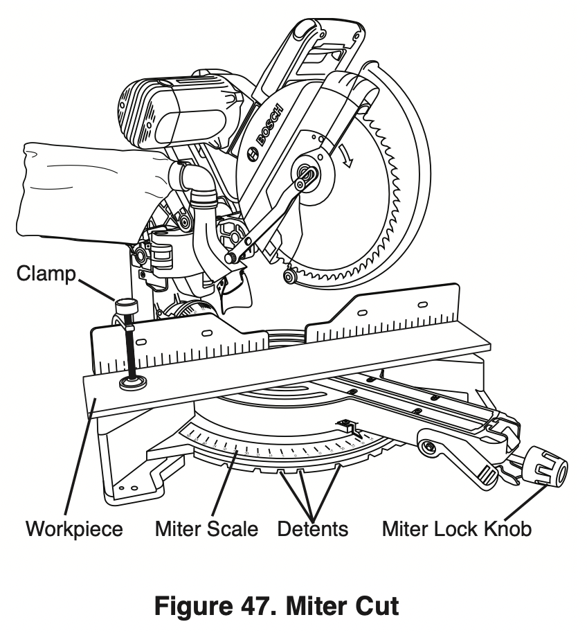
- Loosen the miter lock knob. Lift miter detent lever and move the saw to the desired angle, using either the detents or the miter scale. Tighten miter lock knob (see Figure 47).
- Properly position workpiece. Make sure workpiece is clamped firmly against the table or the fence.
WARNING: Use a clamping position that does not interfere with operation. Before switching “ON” saw, lower saw head to make sure the clamp clears guard and head assembly.
- Follow procedures for either chop cut or slide cut (see pages 34-35).
- Wait until saw blade comes to a complete stop before returning head to the raised position and then remove workpiece.
Bevel Cuts
What’s a Bevel Cut – Saw features
- A “bevel cut” is a cross-cut made with the blade perpendicular to the fence and with the table set at 0° miter. The blade can be tilted to any angle within the saw’s range: the left is 0 to 47° and the right is 0 to 47°.
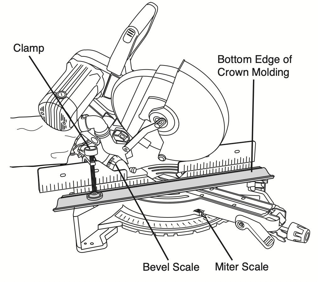
- The bevel scale is sized and positioned for easy reading – see Figure 48.
Note: when performing right and left bevel cuts it is necessary to move the sliding fence away from the blade to avoid cutting into the fence. When compound cutting on the right it will be necessary to remove the right siding fence – see page 29.
Bevel range selector knob – This saw has a front control on the right side of the table arm. This is called the bevel range selector knob (item 41 – page 9). It is linked to stops and locking mechanisms in the rear which control the tool’s ability to quickly and accurately be positioned to make bevel cuts. There are positive stops at0°(theimportant45°left, vertical), and 45° right angles (see Figure 49).
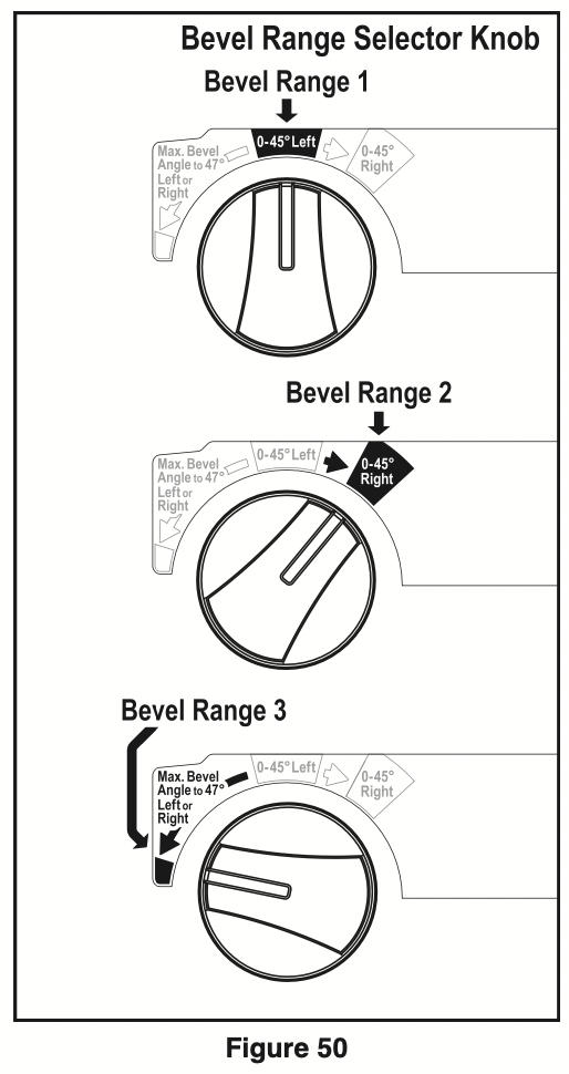
Using the Bevel Range Selector Knob
Bevel Range 1 = 0-45° left
This left-side bevel range is the default setting.
To operate in Bevel Range 1:
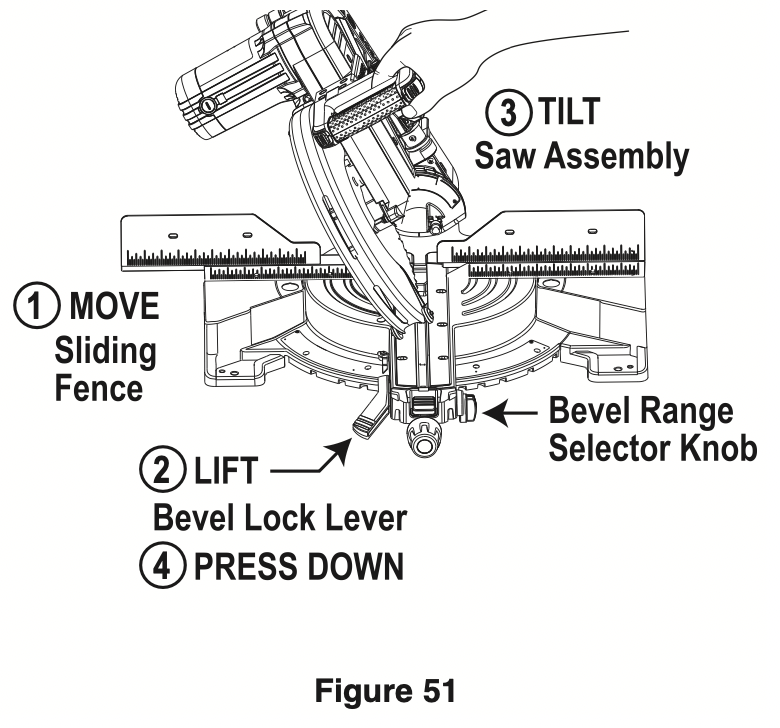
- Move the left sliding fence out to clear saw assembly and relock (Figure 51).
- Lift bevel lock lever above table height with left hand.
- Grasp the main handle with the right hand and tilt the saw assembly to the angle desired.
- Once in the desired bevel position, hold the saw assembly with right hand and use left hand to fully press down the bevel lock lever below table height.
NOTE: Without turning the saw “ON,” perform a dry cut to make sure the fence clears the guards and adjust if necessary.
Bevel Range 2 = 0-45° Right
To operate in Bevel Range 2:
- Move the right sliding fence out to clear saw assembly and relock (see Figure 51).
- Lift bevel lock lever above table height with the left hand.
- Grasp the main handle with the left hand and tilt the saw assembly slightly to the left while rotating the spring-loaded bevel range selector knob with the right hand so the knob’s indicator points to “045° Right” as on the label.
- Once in the desired bevel position, hold the saw assembly with right hand and use left hand to fully press down the bevel lock lever below table height.
NOTE: When the saw assembly is tilted back to left past 0°, the bevel control knob will snap back to the default bevel range 1. This is designed to regain the preset bevel stop at the important 0° position.
Bevel Range 3 = Max. Bevel Angle to 47° left or Right
This full-capacity bevel range setting overrides all preset stops and allows for cutting at bevel angles beyond the normal 45° on either side.
To operate in Bevel Range 3:
- Move the left and right sliding fences out to clear saw assembly and relock (see Figure 51).
- Lift bevel lock lever above table height with the left hand.
- Grasp the main handle with the left hand and tilt the saw assembly slightly to the left while rotating the spring-loaded bevel range selector knob with the right hand so the knob’s indicator points to the red square below “Max. Bevel Angle to 47° Left or Right.”
- Once in needed bevel position, hold saw head by the right hand and use left hand to press down the bevel lock lever below table height.
NOTE: The selector knob will stay in this “override” position. Turn the knob slightly clockwise and it will snap back to bevel range 1 (default position).
WARNING: For bevel cutting, adjust sliding fence clear of blade path and guard system.
Bevel Angle Stops and Detents
- The saw has bevel angle stops that accurately stop at critical angles: 45° left, 0°, and 45°. It comes factory-set and should not need to be adjusted. However, after extensive use or if the tool has received a hard impact, it may require an adjustment.
- The saw has a bevel angle detent pin which can only be engaged at 33.9° left or right - this is the bevel angle required when cutting 38° “spring angle” crown molding flat on the table. NOTE: If the bevel detent pin automatically engages at 33.9° and prevents tilting the saw to another angle, simply pull it to the front and rotate its cross pin 1/4 turn so it rests in the disengaged position. If pin is sticking in, tilt and rock saw head side to side as you pull on it (see Figure 52).
Setting Saw to Make a Bevel Cut
- Lift up the bevel lock lever to unlock (see item 14 – page 8).
- Choose the desired bevel range using the bevel range selector knob. NOTE: If in the 0° position and moving to “0-45° Range,” it may be necessary to move the head assembly slightly to the left before the selector knob can be turned.
- Grasp the main handle and tilt the saw head assembly to the desired angle while watching one of the bevel angle pointers – watch the right pointer when tilting to the left or the left pointer when tilting to the right.
- Continue to hold saw and push down on the bevel lock lever (with your left hand) to lock. Let go of tool.
- Follow the chop cut or slide cut procedures in this manual.
Compound Cuts
WARNING: For compound cutting, adjust sliding fence clear of blade path and guard system.
WARNING: Before sawing, always check that there is no interference between moving and stationary parts of the saw. Do not operate the saw in the following range of miter and bevel47°pcombinations:leftBevel45°to lUS Right Miter 46° to 55°. These miter and bevel combinations may result in interference between the sliding and stationary parts of the saw or between the sliding parts and the work piece.
What’s a Compound Cut – Saw features
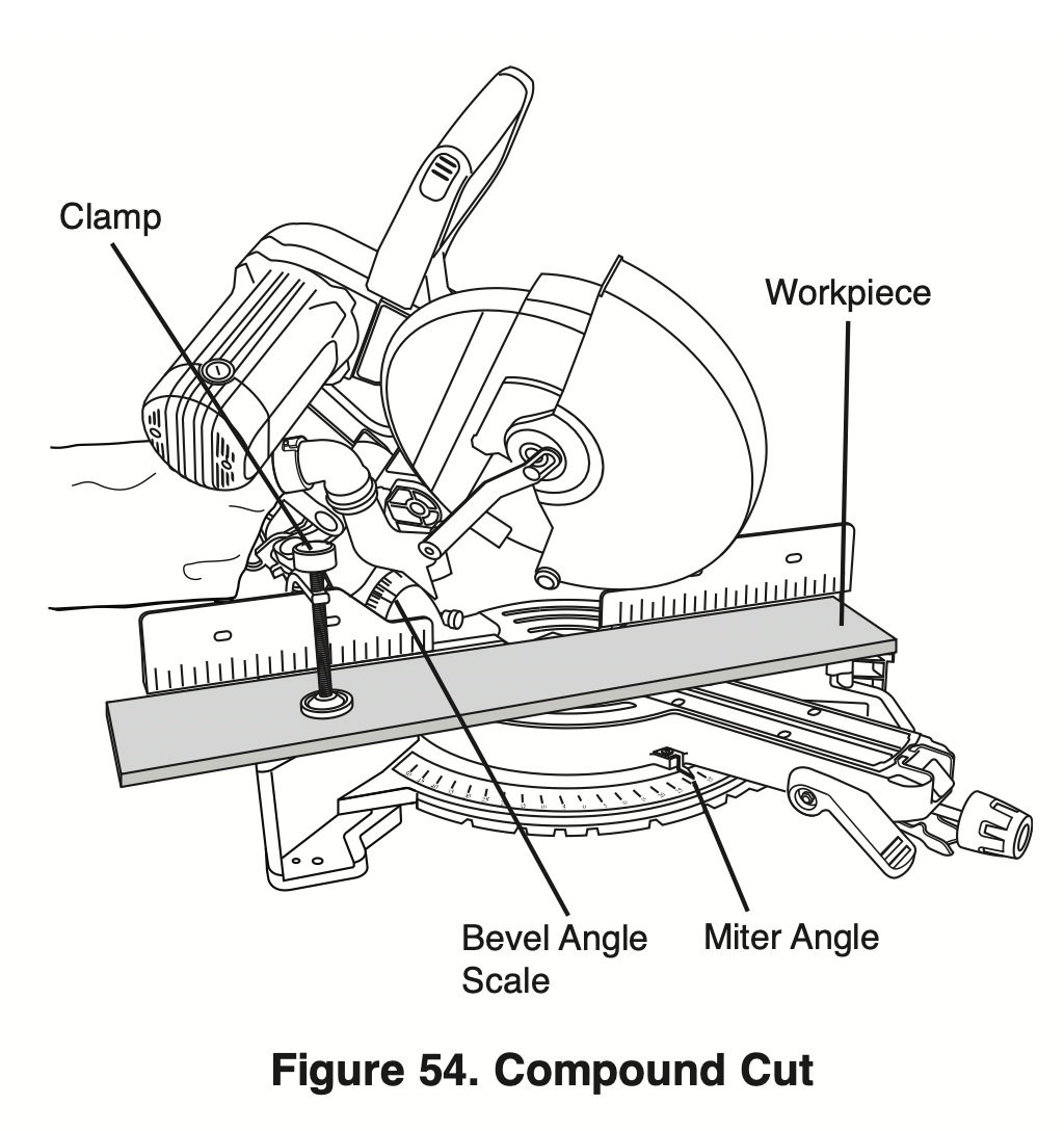
- A “compound cut” is a single cross-cut made with the saw blade preset at two angles combining a miter angle (relative to the vertical fence) with a bevel angle (relative to the horizontal table).
- Miter angles will be with the table rotated away from 0° and within this saw’s range from 52° left to 60° right.
- A bevel angle is when the blade is tilted away from 0°. This saw’s47°rrangeisfrom47°leftto ight.
NOTE: If the bevel detent pin automatically engages at 31.6° and prevents tilting the saw to another angle, simply pull it to the front and rotate its cross pin 1/4 turn so it rests in the disengaged position. If pin is sticking in, tilt and rock saw head side to side as you pull on it.
- A compound cut can be made as a chop cut or a slide cut.
- Cutting crown molding flat on the table requires compound cuts. See Cutting Crown Molding section on page 45.
- When performing compound cuts it will be necessary to move the sliding fence away from the blade. Some compound cuts may require the removal of the fence, refer to page 29.
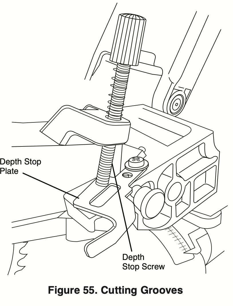
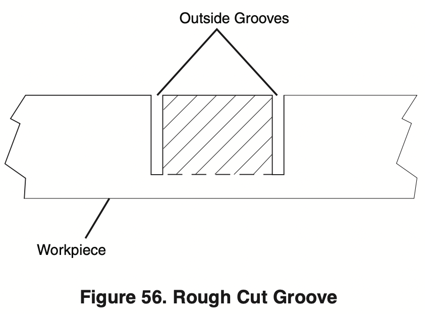
Cutting Grooves
The depth stop adjustment is a feature used when cutting grooves in the workpiece.
The depth adjustment is used to limit blade depth to cut grooves.
NOTE: Read and understand all instructions on page 19 in the Adjustments section on “Setting Blade Depth for Non-Through Cuts for Cutting Grooves.”
NOTE: For best results, Bosch recommends the use of a table saw with an optional dado blade set for cutting grooves and non-through cuts. In the event this is not available, the feature described below is a convenient alternative.
A groove should be cut as a slide cut.
- For adjustment of groove depth, pull out depth stop plate and rotate depth stop screw. Rotating the depth stop screw clockwise will raise saw blade and rotating the screw counterclockwise will lower the blade.
- For minor adjustments, simply rotate the depth stop screw to the desired location.
- Cut the two outside grooves first.
- After cutting a groove, shut saw “OFF” and wait for blade to stop.
- To remove material between cuts, move the workpiece to the right or left. The saw must come to a complete stop before moving workpiece.
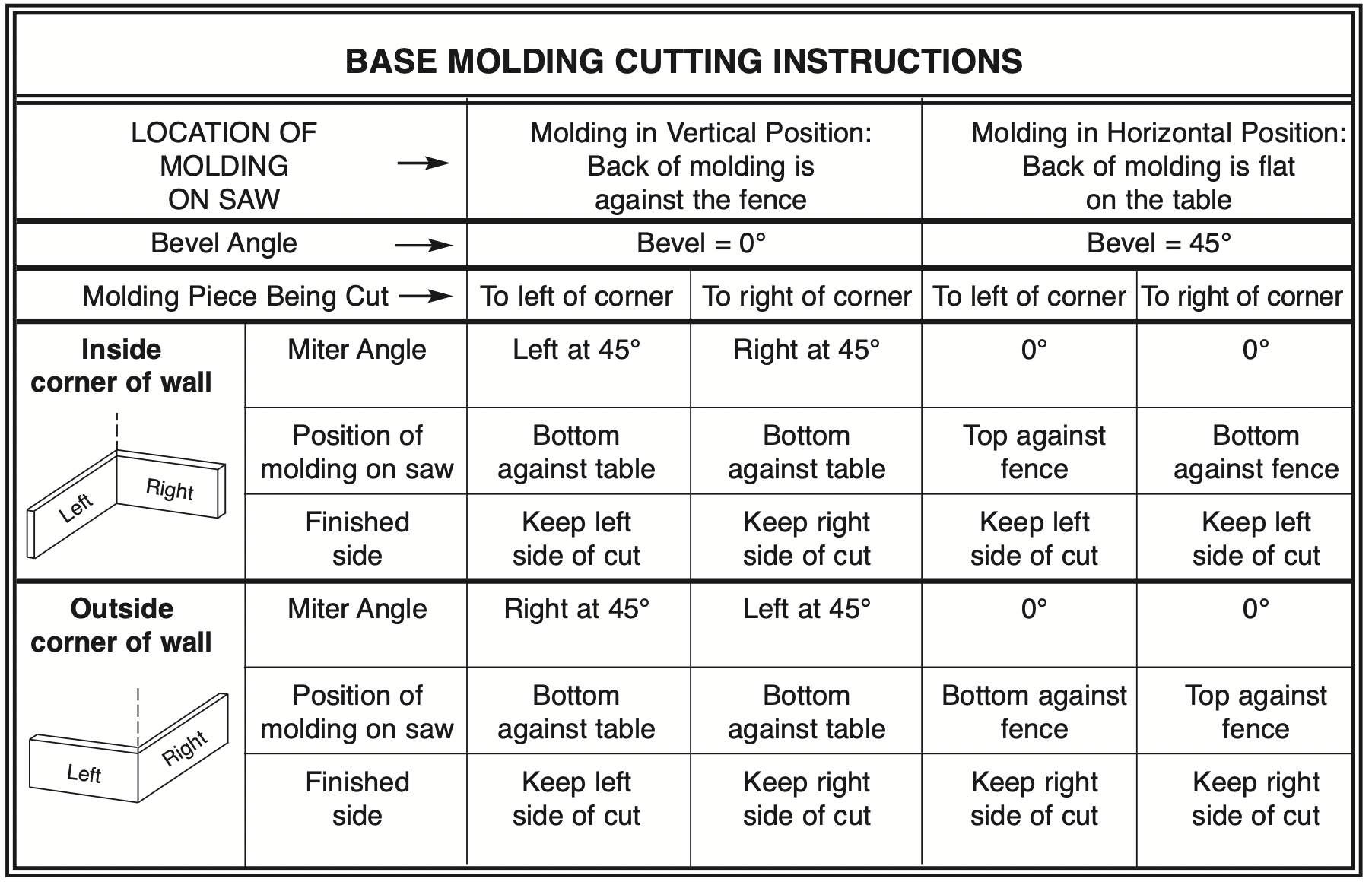
Cutting Base Molding
- Base molding can be cut vertical against fence or flat on the table. The maximum size that can be vertical on the fence is 5-1/2", flat on table is 12-1/2".
- Follow the table for helpful hints on cutting base molding for corners that have 90° angles.
- Cutting base molding can be done either as a chop cut or a slide cut depending on the size of the workpiece.
Cutting Crown Molding
Crown molding cuts must be positioned properly to fit exactly.
There are two ways to cut crown molding: flat on table or angled to table and fence.
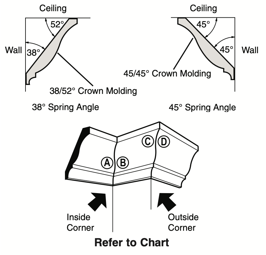
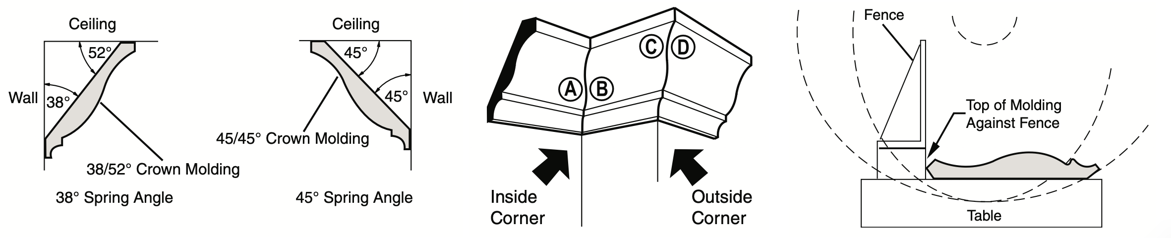
Crown molding’s “spring angle” is the angle between the back of the molding and the bottom flat surface that fits against the wall.
This miter saw has special miter detents at 31.6° and bevel detents at 33.9°. These detents allow you to easily position most crown molding flat on the table and make precise cuts for 90° corners. NOTE: These detents cannot be used with 45° crown molding. These detents are only for use with crown molding that has a 38° “spring angle.”
See also pages 46 & 47 for miter and bevel angle charts for cutting crown molding that has 38° and 45° spring angles. Each chart lists the exact miter and bevel settings required for a wide range of corner angles.
Even though these angles are standards, most rooms do not have angles of exactly 90°; therefore, you will need to fine-tune your settings.
The optional Bosch DAF220K MiterFinder Digital Anglefinder/Protractor measures spring angles and corner angles, then automatically determines the exact miter and bevel settings necessary to make each crown molding cut fit perfectly.
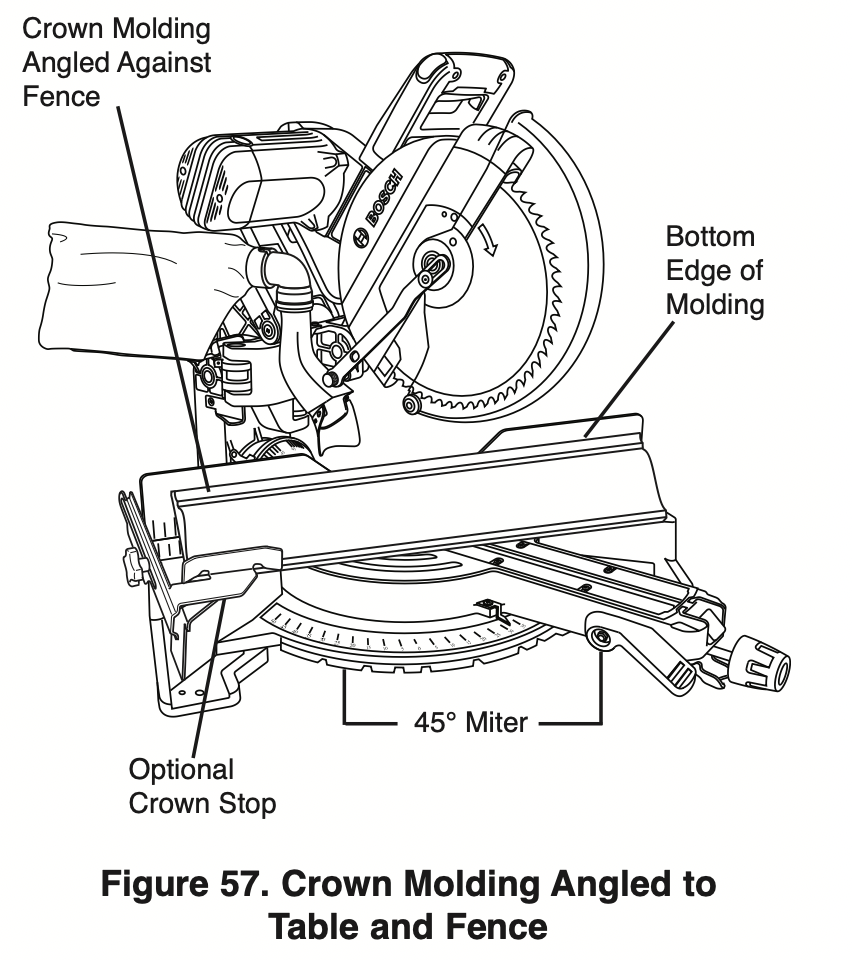
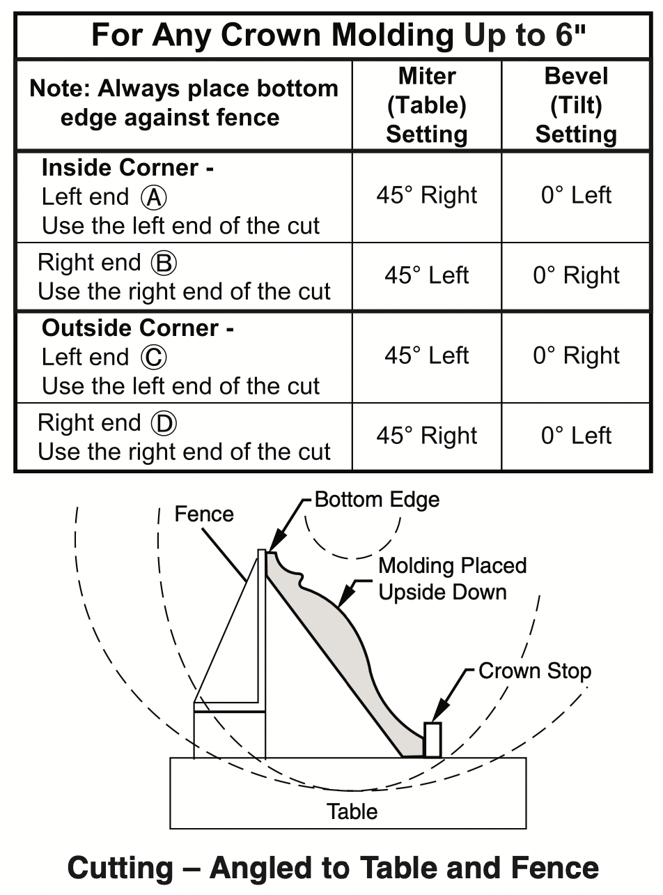
Crown Molding Angled to Table and fence
The preferred method for cutting crown molding with this saw is with the molding lying flat on the table.
The advantage to cutting molding angled against fence is that no bevel setting is required. Only the miter angle is adjusted.
The maximum crown molding width that can be cut and angled to table and fence is 5-1/2".
When cutting crown molding in this fashion it is recommended to purchase and use the optional Crown Stop Set (see page 55).
Follow these instructions for cutting crown molding angled to table and fence.
- Position the molding so the bottom (decorative part, which is installed against the wall) is against the fence.
- For 90° corner, set the miter angle using chart below. Tighten the miter lock knob.
- Support crown molding against the fence (see “Body and Hand Position” on page 28.)
- Follow the procedures for chop or slide cut (see pages 34-35).
- Wait until blade comes to a complete stop before returning head assembly to the raised position and/or removing workpiece.
NOTE: Always take a test cut using scrap to confirm correct angles.
Miter and Bevel Settings for Standard Crown Molding Cuts (When Workpiece Angled Against fence)
Assumptions: Molding is milled consistently. Corner is 90°.
For other corner angles, divide actual measurement by 2.
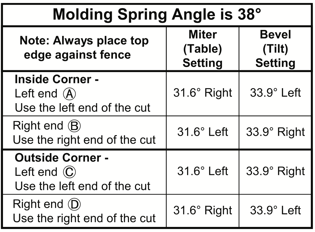
Crown Molding lying flat on Table
NOTE: Position workpiece with its back flat on the saw table.
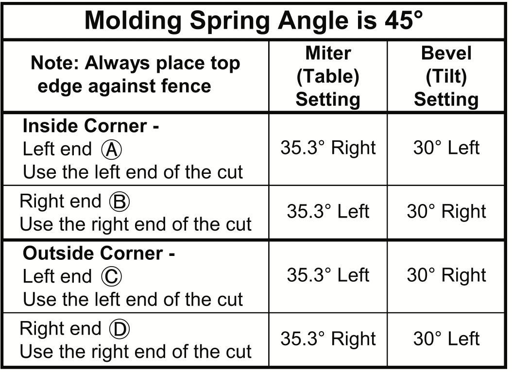
Always place top edge of molding against fence (decorative edge is at the bottom of crown molding.)
“Spring angle” refers to angle between wall and crown molding.
Cutting crown molding flat on the table can be done either as a chop cut or a slide cut depending on the width of the workpiece.
Refer to special auxiliary fence for narrow cutoffs when cutting crown flat on table (see page 48).
- For 90° corner, set the bevel and miter angles using charts below. Tighten the miter lock knob and the bevel lock lever.
- Position molding on saw table. Clamp workpiece in place using the quick clamp.
WARNING: Use clamping position that does not interfere with operation. Before switching “ON,” lower head assembly to make sure clamp clears guard and head assembly.
- Follow procedures for either chop cut or slide cut (see pages 34-35).
- Wait until blade comes to a complete stop before returning head assembly to the raised position and/or removing workpiece.
NOTE: Always take a test cut using scrap to confirm correct angles.
Miter and Bevel Settings for Standard Crown Molding Cuts
(With Molding flat on Table) Assumptions: Molding is milled consistently. Corner is exactly 90°.
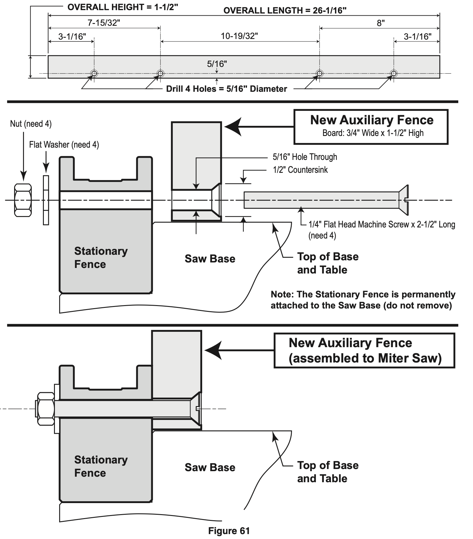
Crown Molding Auxiliary fence
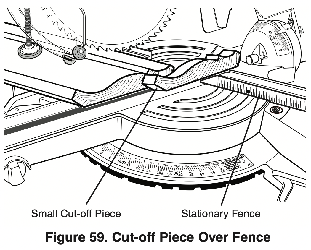
WARNING: When making a compound cut on a molding lying flat on the table, narrow cut-off pieces (2" or less in width) may be propelled at high speed over the fence and beyond the back of the tool (see figure 59). Use auxiliary fence as instructed and shown in figures below.
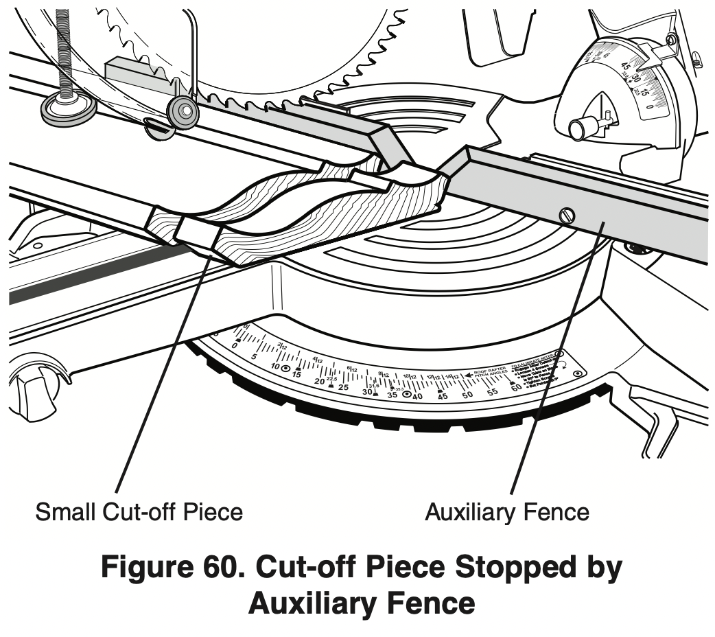
An auxiliary fence is used to add support to the cutoff workpiece such as large crown molding when cut flat on the table (see Figure 60). It will reduce splintering and movement of the unsupported cut-off piece of wood after the cut is made.
Making an Auxiliary fence:
Required pieces:
Wood Board (described below)
4 – Flat Head Machine Screws – 1/4" diameter; 2-1/2" long
4 – 1/4" Flat Washers
4 – Nuts
- Cut a nominal 1" x 2" wood board to a length of 261/16" long. NOTE: 1 x 2" nominal equals 3/4" x 1-1/2" actual. 3/4" plywood cut to size may be substituted.
- Drill four holes through the board using a 5/16" diameter drill bit. Countersink the holes deep enough so that the flat head screws will rest below the front work surface – use a 1/2" diameter drill bit (see Figure 61).
Remove the sliding fences from the tool – see page 29.
- Place the flat head screws through the holes in the auxiliary fence, then the holes in the stationary fence on the tool.
- Place the washers and nuts over the screw threads and against the stationary fence. Tighten nuts.
First-Time Use of the Auxiliary fence:
NOTE: The first time the auxiliary fence is used, it will be cut through by the saw blade – cutting through creates minimal clearance which reduces splintering on the workpiece. Set the miter angle and the bevel angle required before making the first cut. Clamp the workpiece, then make cut – example: compound cutting large crown molding flat on the table (see Figure 58).
Auxiliary Fence - Using an Auxiliary Fence when cutting Crown molding flat on the table will reduce splintering of your workpiece and movement of small cut-off pieces. Remove the saw’s sliding fences (see page 29) before attaching the auxiliary fence.
Build auxiliary fence by following pattern below - Material: 3/4" x 1-1/2" wood.
Add 4 holes as dimensioned on pattern -or- Add holes following the next steps:
- Cut wood to the outside dimensions shown and temporarily attach to saw’s stationary fence using two C-clamps.
- Use 1/4" drill bit to drill first through existing holes in the rear of the stationary fence and then through the wood.
- Remove wood, countersink the front of the wood and permanently attach to saw’s fence with hardware shown below.
Special Cuts
Cutting bowed material and round material are only two examples of special cuts.
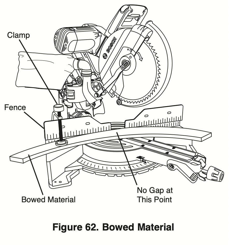
Cutting Bowed Material
If workpiece is bowed or warped, clamp it with the outside bowed face toward the fence. Always make certain that there is no gap between the workpiece, fence and table along the line of cut. Bent or warped workpieces can twist or rock and may cause binding on the spinning saw blade while cutting (see Figure 62).
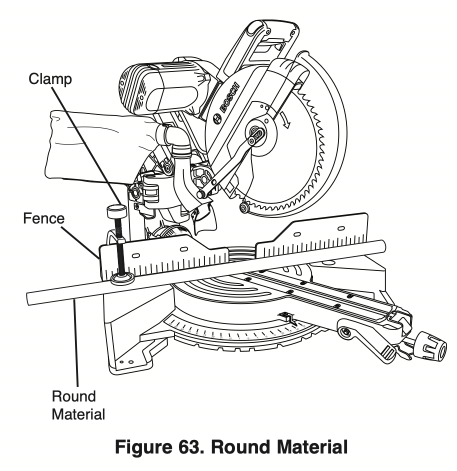
Cutting Round or Irregularly Shaped Material
For round material such as dowel rods or tubing, always use a clamp or a fixture designed to clamp the workpiece firmly against the fence and table. Rods have a tendency to roll while being cut, causing the blade to “bite” and pull the work with your hand into the blade (see Figure 63).
Maintenance and lubrication
Service
WARNING: Preventive maintenance performed by unauthorized personnel may result in misplacing of internal wires and components which could cause serious hazard. We recommend that all tool service be performed by a Bosch factory Service Center or Authorized Bosch Service Station.
Motor Brushes
The brushes and commutator in your tool have been engineered for many hours of dependable service. To maintain peak efficiency of the motor, we recommend every 2-6 months the brushes be examined. Only genuine Bosch replacement brushes specially designed for your tool should be used.
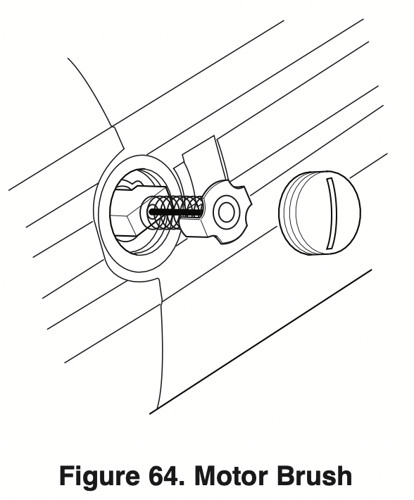
Motor Brush Replacement
To inspect or replace brushes:
- Unplug the saw.
WARNING: The brush cap is spring-loaded by the brush assembly.
- Remove the brush cap on the motor using a wide, flat-blade screwdriver.
- Pull out the brush (see Figure 64). Repeat for the opposite side.
NOTE: If installing the existing brush or brushes, make sure the brush goes in the same way it came out. Otherwise, a break-in period will occur that will reduce motor performance and increase brush wear.
- Inspect brushes for wear. On the wide, flat side of brush is a wear limit line. If the brush contact face is at or beyond (no line visible) the limit, replace brushes as a set.
- Install new brush. The two tabs on the brush terminal go in the same hole the carbon part fits into.
- Tighten the brush cap but do not overtighten.
Drive Belt
The drive belt is a long life component; however, after extensive use, it may require cleaning or replacement. Dust and debris may enter through the ventilation system and affect the performance of the belt. Periodically, the drive belt should be inspected for excessive wear. If the belt shows signs of drying out, cracking or tearing, it should be replaced. If the belt will not track properly or comes off the pulleys, it should be replaced. Belt replacement should only be performed by an authorized service center.
Cleaning / Inspecting Drive Belt:
- Unplug the saw.
- Remove the two belt cover screws using a #2 Phillips screwdriver.
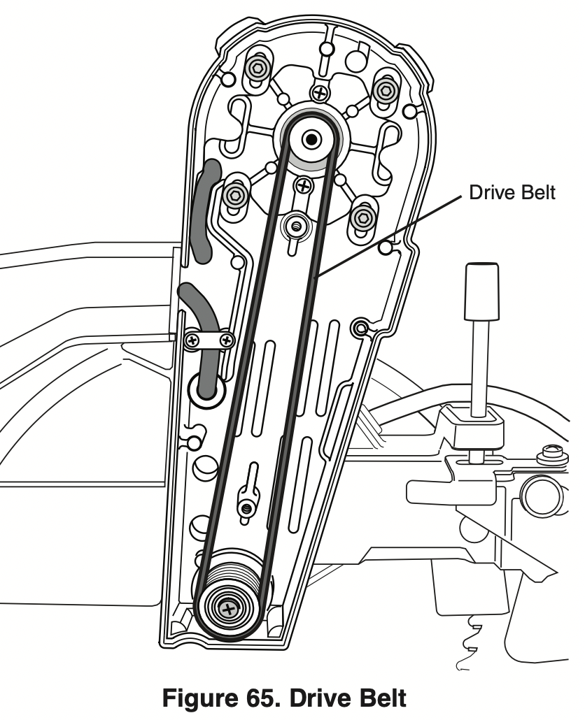
- Clean area with a brush or compressed air.
- Inspect the belt. If dried out, cracked or excessively loose, it may require service and/or replacement.
WARNING: To avoid possible injury, do not attempt to replace the drive belt (replacement requires special tools). Take saw to an authorized Bosch service center.
- Replace belt cover and two cover screws.
Cleaning
WARNING: To avoid the accidents, always disconnect the tool from the power supply before cleaning or performing any maintenance. The tool may be cleaned most effectively with compressed air. Always wear safety goggles when cleaning tools with compressed air.
Ventilation openings and switch levers must be kept clean and free of foreign matter. Do not attempt to clean by inserting pointed objects through openings.
Check regularly to make sure the lower guard and all moving parts are working properly.
Remove accumulated sawdust from working parts by blowing with compressed air or wiping with a damp cloth.
WARNING: Certain cleaning agents and solvents damage plastic parts. Some of these are: gasoline, carbon tetrachloride, chlorinated cleaning solvents, ammonia and household detergents that contain ammonia.
Care of Blades
Blades become dull even from cutting regular lumber. If you find yourself forcing the saw forward to cut instead of just guiding it through the cut, chances are the blade is dull or coated with wood pitch.
When cleaning gum and wood pitch from blade, unplug the saw and remove the blade. Remember, blades are designed to cut, so handle carefully. Wipe the blade with kerosene or similar solvent to remove the gum and pitch. Unless you are experienced in sharpening blades, we recommend you do not try.
Tool Lubrication
Your Bosch tool has been properly lubricated and is ready to use. It is recommended that tools with gears be regreased with a special gear lubricant at every brush change.
Periodically lubricate moving parts with a silicone, or light oil spray. Do not use grease because it tends to attract and hold sawdust.
Bearings
All bearings in this tool are lubricated with a sufficient amount of high-grade lubricant for the life of the unit under normal operating conditions. No further lubrication is required.
Troubleshooting
Electrical
|
PROBlEM
|
CAUSE
|
CORRECTIVE ACTION
|
|
Brake does not stop blade in about 5 seconds.
|
- Brushes not seated or lightly sticking or worn.
- Motor overheated from use of dull blade/too heavy of a blade, not recommended accessory or rapid on/off cycling.
- Blade bolt loose.
- Other.
|
- Inspect/clean or replace brushes (see Maintenance and Lubrication section).
- Use sharp blade.
- Use a recommended blade.
- Let saw cool down.
- Tighten blade bolt.
- Authorized service.
|
|
Motor does not start.
|
- Check that unit is plugged in.
- Power source fuse or time delay fuse.
- Brushes worn.
- Other.
|
- Plug unit in. Use different outlet.
- 15-Amp time delay fuse or circuit breaker.
- See Motor Brush Replacement in the Maintenance and Lubrication section.
- Authorized service.
|
|
Flash of light from motor end cap when switch is released.
|
Normal - brake working properly.
|
|
General
|
PROBlEM
|
CAUSE
|
CORRECTIVE ACTION
|
|
Head assembly does not bevel to desired position.
|
- Bevel detent pin is engaged. And locks bevel angle at 33.9°.
- Bevel range selector knob setting limits movement.
|
- Pull out 33.9° bevel detent pin, then rotate pin 1/4 turn to keep out.
- Change bevel range selector knob position (see page 41).
|
|
Blade hits table.
|
Misalignment.
|
|
|
Angle of cut not accurate.
|
Angle stops at 0° or 45° need adjustment.
|
- See Adjustments section (pages 20-25).
|
|
Cannot rotate table to change miter angle.
|
- Miter lock knob is tightened.
- Miter detent lever is engaged with adetent (slot) in detent plate.
- Sawdust accumulation.
|
- Turn miter lock knob counter clockwise to loosen.
- Pull up on miter detent lever to disengage from detent slot (see page 33).
- Vacuum or blow out dust around turntable; wear eye protection.
|
|
Head assembly will not fully raise or blade guard will not fully close.
|
- Head assembly lock pin is engaged.
- Cover plate not tightened after replacing blade.
- Sawdust accumulation.
- Sawdust accumulation.
|
- Pull out lock pin, allowing head assembly to go up (see page 17).
- See Removing and Installing Blades on pages 13-14.
- Clean head assembly.
- Authorized service.
|
|
Blade binds, jams, burns wood. Rough cuts.
|
- Improper operation.
- Dull blade.
- Improper blade.
- Bent blade.
|
- See Saw Operations section.
- Replace or sharpen blade.
- Replace with 10” diameter blade designed for material being cut.
- Replace blade.
|
|
Head assembly slides forward and back when making a chop cut.
|
Mechanism lock lever is disengaged.
Chop/Crown Lock is disengaged.
|
- Pull up on mechanism lock lever tab to engage (seepage 18).
- Engage the Chop/Crown Lock by lifting into desired position (See page 32).
|
|
Bevel angle is not securely held when bevel lock lever is pushed.
Glide mechanism is difficult to move forward and back.
|
Bevel lock lever needs tension adjustment.
|
- Increase bevel lock lever force by adjusting tension nut (see page 25).
|
|
Glide movement controller is set too tight.
|
- Loosen two screws on the movement controller (see page 17).
|
|
Tool vibrates or shakes.
|
- Saw blade not round.
- Saw blade damaged.
- Saw blade loose.
- Other
|
- Replace blade.
- Replace blade.
- Check that blade is properly seated on the inner washer. See Removing and Installing Blades on pages 13-14.
- Authorized service.
|
|
Head assembly does not slide freely when attempting a slide cut.
|
Mechanism lock lever is engaged.
|
- Push down on mechanism lock lever to disengage (see page18).
|
|
Blade does not cut completely through work piece.
|
- Depth stop plate is pulled out for non-through cuts.
- Replacement blade is less than 10” diameter.
|
- Push depth stop plate in ward to set for full-depth cuts (see page 19).
- Change to a blade that is fully 10” diameter.
|
|
Saw blade or lower guard cuts or contacts sliding fence when saw is set for bevel cuts.
|
Sliding fence is not moved out from path of saw blade before making bevel cut.
|
- Move sliding fence to be clear of lower guard and saw blade; perform a “dry cut” to check for clearances before making bevel cuts (see page 41).
|
|
Bevel angle is not securely held when bevel lock lever is locked.
|
Bevel lock lever needs tension adjustment.
|
- Increase bevel lock lever tension by adjusting lock nut (see page 25).
|