54-40-6926
BULLETIN NO.
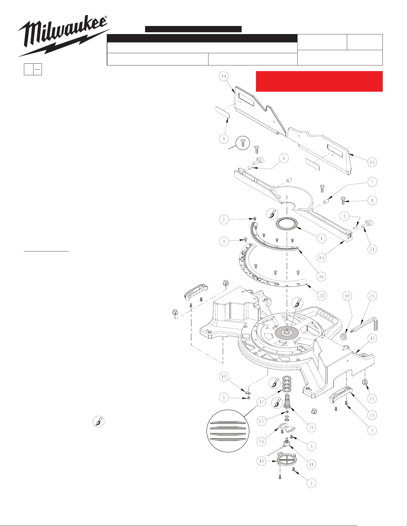
FIG. PART NO. DESCRIPTION OF PART NO REQ.
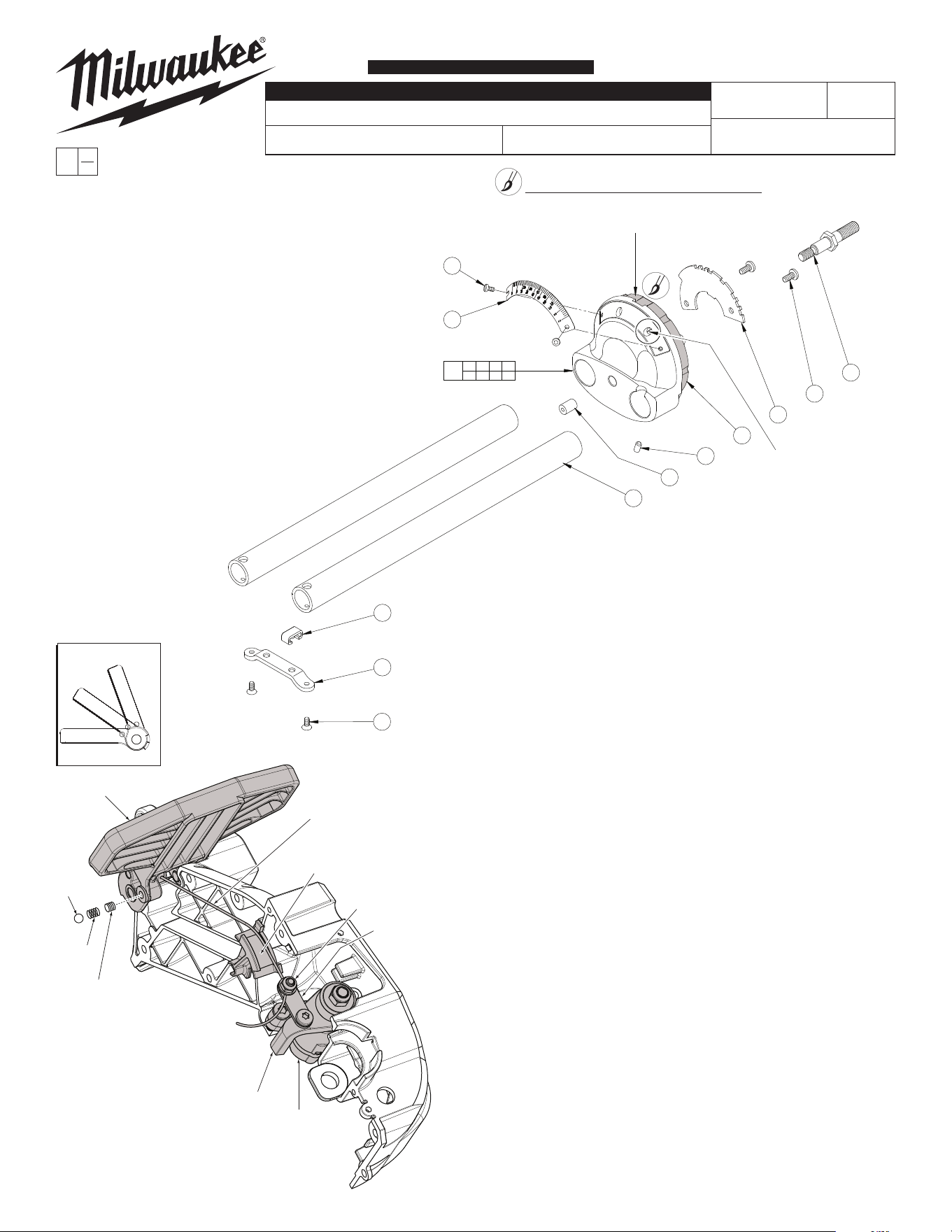
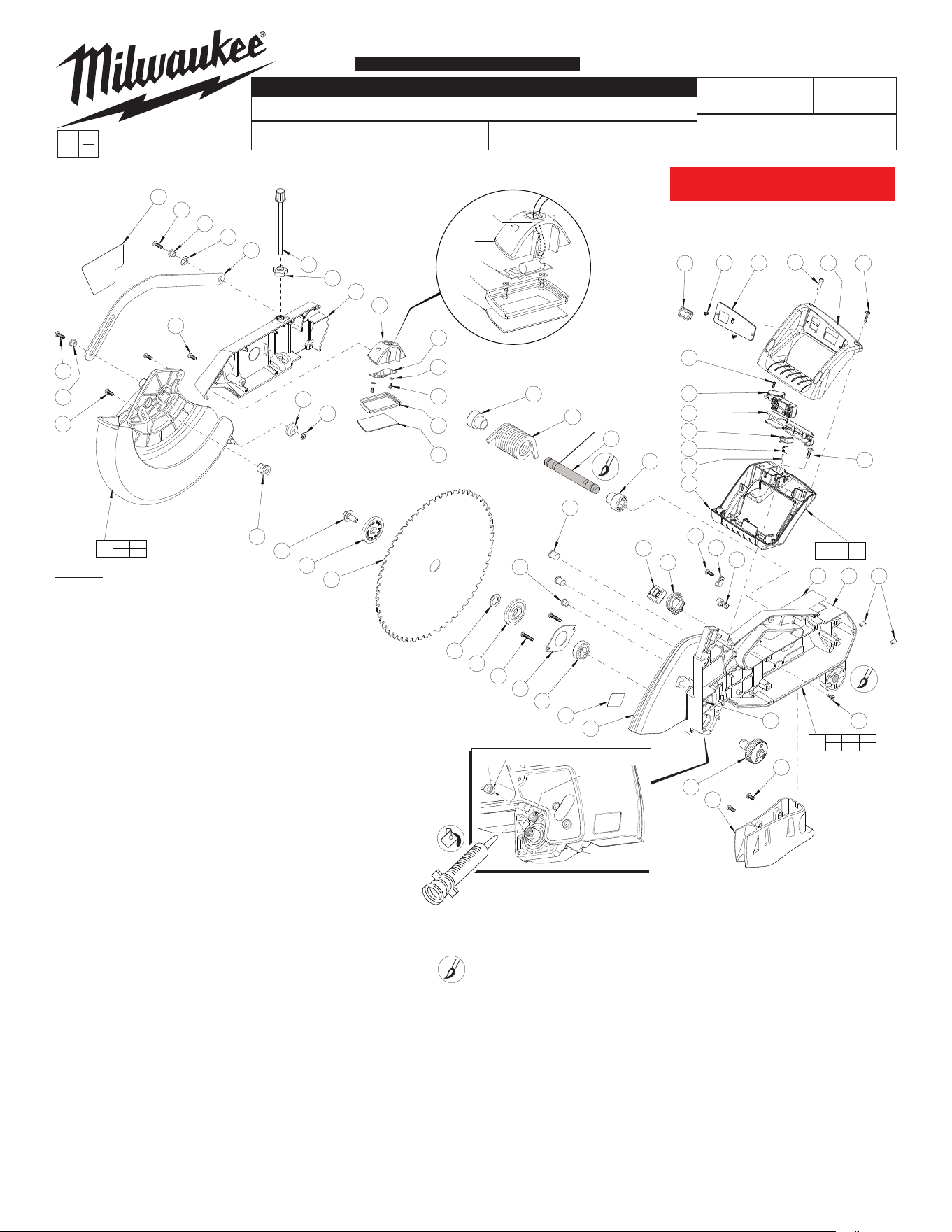
1 02-80-0050 Thrust Bearing (1)
2 05-80-0510 M5 x 12mm Flat Head T-20 Screw (5)
3 05-81-0135 M5 x 13mm Pan Head T-25 Screw (8)
4 05-81-0150 M8 x 25mm Pan Head T-45 Screw (4)
5 05-81-0235 M5 x 7mm Pan Head T-25 Screw (1)
6 05-86-0640 M5 x 18mm Hex Socket Set Screw (1)
7 05-86-0660 M12 x 1 x 18mm T-25 Socket Set Screw (2)
8 05-89-0530 M5 x 13mm Pan Hd T-25 Shoulder Scr (5)
9 10-20-9115 Fence Label (2)
10 22-38-0175 Cable Clamp (1)
11 23-45-0010 Potentiometer
(Incl. Hex Nut & Star Washer)
(1)
12 28-06-1260 12" Sliding Miter Base (1)
13 28-35-0105 Fixed Fence (1)
14 28-35-0110 Left Fence (Moving Fence) (1)
15 28-35-0120 Right Fence (1)
16 32-48-0121 Rack (1)
17 40-50-8620 Belleville Spring (4)
18 22-90-0260 Grommet (1)
19 42-92-1130 Potentiometer Cover (1)
20 43-82-0165 Miter Scale (1)
21 43-98-0275 Lock Knob Bolt (2)
22 44-34-0025 Miter Base Foot (4)
23 44-52-0950 Handle Grip (2)
24 44-66-0970 Potentiometer Plate (1)
25 49-96-0180 1/4" Hex / T-25 Blade Wrench (1)
60 42-90-0130 Tolerance Ring (1)
76 45-08-0455 Table Bolt (1)
SERVICE NOTES:
Orient Thrust Bearing #1 with printed ID stripe up,
facing away from Base #12.
When assembling the Fixed Fence #13 to the Base #12,
secure the left most Screw #4 as illustrated, followed by
the other three screws.
Moving Fence Adjustment: (Left Fence)
A. Turn Set Screw #7 (located on left side of Fixed
Fence #13) clockwise until Set Screw touches Moving
Fence#14,thenbacko1/8to1/4turn.
B. The Moving Fence #14 must be able to be rotated and
slide past the Set Screw #6.
C. Set Screw #6 must protrude past machined surface of
Fixed Fence #13.
Removable Fence Adjustment: (Right Fence)
A. Turn Set Screw #7 (located on right side of Fixed
Fence #13) clockwise until Set Screw touches
RemovableFence#15,thenbacko1/8to1/4turn.
00
EXAMPLE:
Component Parts (Small #) Are Included
When Ordering The Assembly (Large #).
0
PAGE 1 OF 8 BASE ASSEMBLY
LUBRICATION NOTE
Place a light coat of Type 'Y' grease,
No. 49-08-5270 to Belleville Springs #17.
Belleville Springs are to be assembled in
the order shown.
Place a light coat of Type 'Y' grease,
to both sides of Thrust Bearing #1 and
corresponding center bore of Base #12
as shown.
Place a light coat of Type 'Y' grease,
on the shaft of Table Bolt #76 prior to
inserting through hole in Base #12 and
threading into hole on the bottom of
Table #43 (shown on next page).
Be sure that
Tolerance Ring
#60 is inserted into
hole of Table Bolt #76
prior to inserting the brass
shaft of Potentiometer #11.
Flat of shaft must be
oriented 180º from the
wiring harness. See Wiring
Instruction 58-01-6925 for
Adjustment of 'Zero' on
Base Potentiometer.
58-01-6926
6955-20
12" SLIDING COMPOUND MITER SAW
May 2020
REVISED BULLETIN
54-40-6925
WIRING INSTRUCTION
DATE
SPECIFY CATALOG NO. AND SERIAL NO. WHEN ORDERING PARTS
SERIAL
NUMBER
CATALOG NO.
When attaching
Fixed Fence #13
to the Base #12,
tighten this
screwrst.
«
«
«
B26B or B26C
MILWAUKEE TOOL
l
www.milwaukeetool.com
13135 W. LISBON RD., BROOKFIELD, WI 53005
Drwg. 6
SERVICE PARTS LIST
«= Part number change from
previous service parts list.
This page represents all 6955-20 12" Miter saws on This page represents all 6955-20 12" Miter saws on
or before serial break B26C190800001. Page 2 will or before serial break B26C190800001. Page 2 will
represent anything after serial break stated above.represent anything after serial break stated above.
257
258
259
260
261
262
263
251
251 257 258 259 260
261 262 263 264
265
54-40-6926
BULLETIN NO.
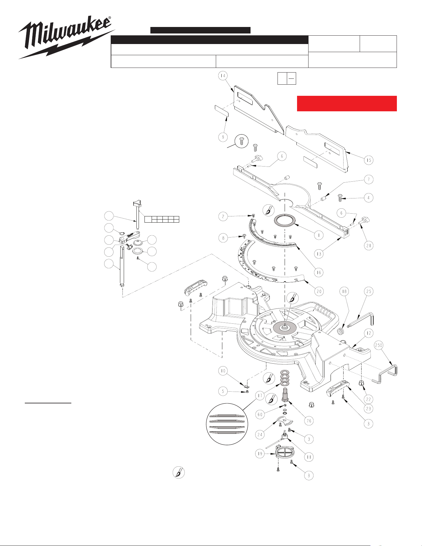
FIG. PART NO. DESCRIPTION OF PART NO REQ.
1 02-80-0050 Thrust Bearing (1)
2 05-80-0510 M5 x 12mm Flat Head T-20 Screw (5)
3 05-81-0135 M5 x 13mm Pan Head T-25 Screw (8)
4 05-81-0150 M8 x 25mm Pan Head T-45 Screw (4)
5 05-81-0235 M5 x 7mm Pan Head T-25 Screw (1)
6 05-86-0640 M5 x 18mm Hex Socket Set Screw (1)
7 05-86-0660 M12 x 1 x 18mm T-25 Socket Set Screw (2)
8 05-89-0530 M5 x 13mm Pan Hd T-25 Shoulder Scr (5)
9 10-20-9115 Fence Label (2)
10 22-38-0175 Cable Clamp (1)
11 23-45-0010 Potentiometer
(Incl. Hex Nut & Star Washer)
(1)
12 28-06-1260 12" Sliding Miter Base (1)
13 28-35-0105 Fixed Fence (1)
14 28-35-0110 Left Fence (Moving Fence) (1)
15 28-35-0120 Right Fence (1)
16 32-48-0121 Rack (1)
17 40-50-8620 Belleville Spring (4)
18 22-90-0260 Grommet (1)
19 42-92-1130 Potentiometer Cover (1)
20 43-82-0165 Miter Scale (1)
21 43-98-0275 Lock Knob Bolt (2)
22 44-34-0025 Miter Base Foot (4)
23 44-52-0950 Handle Grip (2)
24 44-66-0970 Potentiometer Plate (1)
25 49-96-0180 1/4" Hex / T-25 Blade Wrench (1)
60 42-90-0130 Tolerance Ring (1)
76 45-08-0455 Table Bolt (1)
250 42-09-0026 U-Bar Extension Support (2)
251 06-82-0158 M6 x 12mm Pan Hd. T-30 Mach. Screw (1)
257 43-98-0081 Vise Knob (1)
258 42-70-0052 Retaining Ring (1)
259 42-42-0081 Clamp Body (1)
260 43-98-0281 Vise Screw (1)
261 28-10-0016 Vise Rod (1)
262 28-10-0018 Clamp Shoe (1)
263 44-52-0076 Rubber Shoe (1)
265 14-46-0147 Clamp Kit (1)
SERVICE NOTES:
Orient Thrust Bearing #1 with printed ID stripe up,
facing away from Base #12.
When assembling the Fixed Fence #13 to the Base #12,
secure the left most Screw #4 as illustrated, followed by
the other three screws.
Moving Fence Adjustment: (Left Fence)
A. Turn Set Screw #7 (located on left side of Fixed
Fence #13) clockwise until Set Screw touches Moving
Fence#14,thenbacko1/8to1/4turn.
B. The Moving Fence #14 must be able to be rotated and
slide past the Set Screw #6.
C. Set Screw #6 must protrude past machined surface of
Fixed Fence #13.
Removable Fence Adjustment: (Right Fence)
A. Turn Set Screw #7 (located on right side of Fixed
Fence #13) clockwise until Set Screw touches
RemovableFence#15,thenbacko1/8to1/4turn.
00
EXAMPLE:
Component Parts (Small #) Are Included
When Ordering The Assembly (Large #).
0
PAGE 1 OF 8 BASE ASSEMBLY
LUBRICATION NOTE
Place a light coat of Type 'Y' grease, No. 49-08-5270 to Belleville Springs #17. Belleville
Springs are to be assembled in the order shown.
Place a light coat of Type 'Y' grease, to both sides of Thrust Bearing #1 and corresponding
center bore of Base #12 as shown.
Place a light coat of Type 'Y' grease, on the shaft of Table Bolt #76 prior to inserting through
hole in Base #12 and threading into hole on the bottom of Table #43 (shown on next page).
Be sure that
Tolerance Ring
#60 is inserted into
hole of Table Bolt #76
prior to inserting the brass
shaft of Potentiometer #11.
Flat of shaft must be
oriented 180º from the
wiring harness. See Wiring
Instruction 58-01-6925 for
Adjustment of 'Zero' on
Base Potentiometer.
58-01-6926
6955-20
12" SLIDING COMPOUND MITER SAW
REVISED BULLETIN
54-40-6925
WIRING INSTRUCTION
DATE
SPECIFY CATALOG NO. AND SERIAL NO. WHEN ORDERING PARTS
SERIAL
NUMBER
CATALOG NO.
When attaching
Fixed Fence #13
to the Base #12,
tighten this
screwrst.
«
«
«
«= Part number change from
previous service parts list.
B26C
SERVICE PARTS LIST
This page will represent anything after This page will represent anything after
serial break B26C190800001.serial break B26C190800001.
54-40-6926
58-01-6926
B26B or B26C
6955-20
12" SLIDING COMPOUND MITER SAW
REVISED BULLETIN
54-40-6925
BULLETIN NO.
WIRING INSTRUCTION
DATE
SPECIFY CATALOG NO. AND SERIAL NO. WHEN ORDERING PARTS
SERIAL
NUMBER
CATALOG NO.
FIG. PART NO. DESCRIPTION OF PART NO REQ.
27 05-55-0915 M8 Prevailing Torque Nut (1)
28 05-81-0115 M4 x 6mm Pan Head T-20 Screw (1)
29 05-81-0130 M4 x 8mm Pan Head T-20 Screw (5)
30 05-81-0135 M5 x 13mm Pan Head T-25 Screw (20)
31 05-81-0200 M5 x 10mm Pan Head T-25 Screw (2)
32 05-81-0235 M5 x 7mm Pan Head T-25 Screw (1)
33 05-86-0640 M5 x 18mm Set Screw (1)
34 05-88-5910 M3.5 x 8mm Pan Hd Slt T-10 PT Screw (4)
35 05-88-5988 K50 x 35mm Slt Pan Hd T-20 Screw (2)
36 10-20-7900 Fine Adjustment Label (1)
37 10-20-9120 Slide Label (1)
38 10-20-9125 Fine Adjustment Warning Label (1)
39 10-20-2239 Round Label (2)
40 22-09-1580 LCD Assembly (1)
41 22-38-0175 Cable Clamp (4)
42 23-66-0705 Digital Readout Calibration Switch (1)
44 31-01-1575 Switch Mount (Miter) (1)
45 31-12-0030 Bearing Cap (1)
46 32-48-0115 Fine Adjustment Tube Gear (1)
47 --------------- Fine Adjustment Gear (1)
48 32-48-0130 Reduction Gear (1)
49 --------------- Pinion Gear (1)
50 34-60-0020 External Retaining Ring (2)
51 --------------- External Retaining Ring (1)
52 34-60-1450 E-Ring (1)
53 40-50-0390 Spring (1)
54 40-50-0455 Miter Detent Spring (1)
55 40-50-0460 Fine Adjustment Return Spring (1)
56 --------------- Slide Block (1)
57 --------------- Fine Adjustment Chassis (1)
58 --------------- Lock Handle Cap (1)
59 42-52-1040 Spring Cap (2)
60 42-90-0130 Tolerance Ring (1)
61 42-92-1135 Cover (Detent Mech.) (1)
62 43-62-1340 Detent Lever Handle (1)
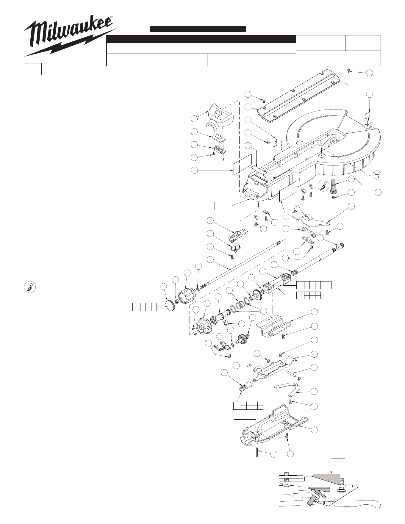
FIG. PART NO. DESCRIPTION OF PART NO REQ.
63 43-76-0740 LCD Cover (1)
64 --------------- Table Lock Knob (1)
65 43-98-0250 Fine Adjustment Knob (1)
66 43-98-0255 Lock Knob Bolt (1)
67 44-06-0030 LCD Lens Cover (1)
68 44-10-0155 Detent Lever (1)
69 44-40-0105 Lock Block (1)
70 44-60-0495 Hinge Pin (1)
71 44-66-0142 Service Kerf Plate (1)
72 44-66-0265 Table Lock Bracket (1)
73 44-66-1125 Miter Lock Plate (1)
74 44-72-0061 Miter Pointer (1)
75 --------------- Handle Lock Rod (1)
76 45-08-0455 Table Bolt (1)
77 --------------- Compound Pinion Tube (1)
78 45-88-3045 Washer (1)
79 --------------- Special Washer (1)
235 14-48-0105 Chassis Assembly (1)
236 14-48-0085 Table Lock Rod Assembly (1)
237 14-48-0095 Fine Adjustment Assembly (1)
238 28-06-1140 Table Assy.
(Incl. 3 linear bearings, not shown)
(1)
249 14-48-0096 Slide Block Assembly (1)
00
EXAMPLE:
Component Parts (Small #) Are Included
When Ordering The Assembly (Large #).
0
5X
4X
4X
5X
2X
2X
2X
2X
2X
46 47 49 51 52
55 56 59 77
237
33 50 53 57
62 68 70
235
27 58 64
75 79
236
36 37
38 39
238
2X
4X
63
67
40
34
36
29
71
74
32
38
28
66
76
60
72
39
49
30
30
41
37
73
44
42
30
75
79
64
27
58
69
31
77
56
51
47
55
46
65
34
59
48
52
78
45
30
50
33
62
57
30
53
68
70
54
30
61
30
35
47 49 51
56 77
249
Table Assembly #238
includes 3 linear
bearings (not shown).
SERVICE PARTS
PAGE 3 OF 8 TABLE ASSEMBLY
LUBRICATION NOTES
Place a light coat of Type
'Y' grease, No. 49-08-5270
to Table Bolt #76.
Table Bolt #76
and Toleance
Ring #60 are
shown for reference/
orientation. Both parts
must be routed through
Washers #17 and
Base #12 prior
to assembly to
Table #43.
ADJUSTMENT OF Digital Readout (DRO) CALIBRATION SWITCH:
A. Turn the Calibration Set Screw #33 in (toward Switch #42) enough
that the calibration switch contacts will not close.
B. With the Miter Detent Spring #54 out of the detent notch in the Miter Detent Scale #20, but resting on the
Miter Scale, move the Table #43 about 1.5° to either side of the “0” position and return to the “0” notch.
C. Insert a 2.5mm hex key into Set Screw #33 and adjust by turning the screw out (clockwise when
viewed from the operators position) until the digital read out changes from the set angle to “0”.
Turn Set Screw #33 an extra 1/4-1/2 turn out.
D. Remove 2.5mm adjustment hex key from Set Screw #33. See Wiring Instruction for more detail.
DRO
CALIBRATION
SWITCH #42
SET
SCREW
#33
Adjustment hole for
Set Screw #33 to
calibrate DRO
Switch #42
Early designs of Switch Mount #44 had individual
spacers. Service replacement has spacers
molded into part.
*
*
80 82 84 85
88 89 90 91
239
85
91
80
81
87
90
88
82
84
86
83
89
54-40-6926
58-01-6926
B26B or B26C
6955-20
12" SLIDING COMPOUND MITER SAW
REVISED BULLETIN
54-40-6925
BULLETIN NO.
WIRING INSTRUCTION
DATE
SPECIFY CATALOG NO. AND SERIAL NO. WHEN ORDERING PARTS
SERIAL
NUMBER
CATALOG NO.
FIG. PART NO. DESCRIPTION OF PART NO REQ.
80 05-80-0510 M5 x 12mm Flat Head T-20 Screw (2)
81 05-81-0130 M4 x 8mm Pan Head T-20 Screw (2)
82 05-86-0650 M5 x .8 x 8mm Hex Socket Set Screw (1)
83 05-89-0535 M6 x 1 x 13mm Pan Head T-25 Screw (2)
84 --------------- Bevel Hub (1)
85 42-38-0395 Bumper (1)
86 43-06-0035 Brake Disk (1)
87 43-82-0160 Bevel Scale (1)
88 45-30-0225 Rubber Slug (1)
89 45-58-0125 Stud (1)
90 --------------- Slide Tube (2)
91 45-98-0030 Tie Bar (1)
239 28-53-0350 Bevel Hub Assembly (1)
00
EXAMPLE:
Component Parts (Small #) Are Included
When Ordering The Assembly (Large #).
0
SERVICE PARTS
PAGE 4 OF 8 HUB ASSEMBLY
LUBRICATION NOTES
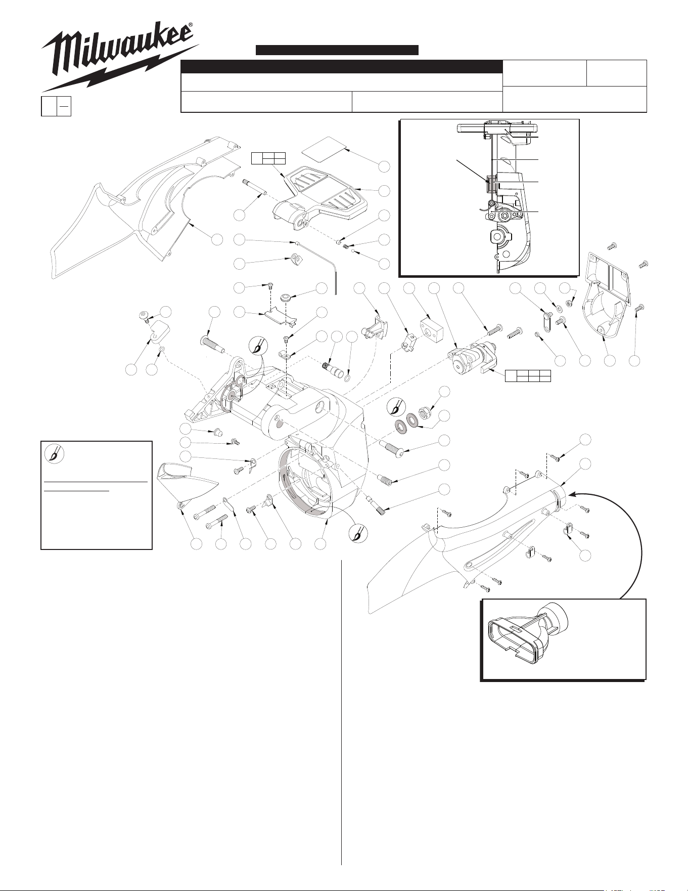
Coat with Type 'Y' grease, No. 49-08-5270.
Diameter and of Bevel Hub #84 to have a
coating of grease. Pockets of diameter to be
lledwithgrease.
Use this hole ONLY
to make Brake adjustments!
Insert a 5mm ball end hex key
through hole in bevel scale
area and engage pad adjuster
on brake. Do not use a
standard hex key for this
adjustment procedure
Brake Release
Handle #118
Brake
Cable
#123
Make sure that Brake
Cable is in the channel
of Cable Guide #126.
Cable Locking
Nut #94
Brake
Assembly
#241
Cable Link
#127
Brake
Lever
This view is shown for reference
purpose only. DO NOT attempt to
disassemble Bevel Arm #112.
See next page for the exploded view illustration
of the components in the Bevel Arm Assembly.
5mm
Ball #92
Spring
#122
Set Screw
#100
NOTE: Exercise caution when
releaving pressure on the Brake
Release Handle. 5mm Ball is
under spring pressure .
1. ADJUSTMENT OF BRAKE CABLE:
(Reference next page for Bevel Arm Assembly)
A. Start with Bevel Release Handle #118, Brake Cable #123, Bevel Brake #241
and Cable Link #127 assembled in Bevel Arm #112. Cable inserted into
Cable Link but not tightened:
B. Move Bevel Release Handle to detent position.
C. Move and hold brake release lever in position by use of a gage block.
C.1 ForSlidingCompoundmodel6955usespecialservicextureNo.61-10-0095.
D. Pull Cable taught using needle nose pliers.
E. Tighten Cable Locking Nut #94 to 45-50 in./lb.
F. Lift Bevel Release Handle to release support of brake lever.
G. Move Bevel Release Handle to locked position.
2. ADJUSTMENT OF STATIONARY BRAKE PAD IN BEVEL ARM:
A. RemoveDustChutes#115,#116andVerticalAirDeector#117.Release
Bevel Brake.
B. Move Bevel Arm to right side hard stop.
C. Block Bevel Release Handle to hold Break in the released position.
C.1ForSlidingCompoundmodel6955usespecialservicextureNo.61-10-0275.
D. Remove Bevel Scale Mounting Screw #81 on right side of Bevel Scale #87,
loosen Scale Mounting Screw on left side of Scale and remove Bevel Scale.
E. Insert a 5mm ball end hex key through right hole in bevel scale area of Bevel
Hub #84 (see illustration) and engage pad adjuster on Brake. Do not use a
standard hex key for this adjustment procedure.
F. Turn pad adjuster to the right until it stops against the Disk #86.
G. Turn pad adjuster to the left 1/8 turn.
H. Remove hex key from break adjuster.
I. ReassembleBevelScale,VerticalAirDeectorandDustChutestosaw.
LOCKED
POSITION
UNLOCKED
POSITION
DETENT
POSITION
104 118
123 136
240
26 94 103
107 127 135
241
133
121
106
118
100
122
92
126
108 124
107
99
127
135
94
97
113
103
26
104
115
123
136
131
102
96
114
111
96
110
119
95
129
117
98 125
97
130 112
93
134
102
101
132
105
116
109
120
128
FIG. PART NO. DESCRIPTION OF PART NO REQ.
26 42-40-0945 Bushing (1)
92 02-02-1300 5mm Ball (1)
93 05-55-0970 M12 Prevailing Torque Nut (1)
94 05-55-0965 M6 Prevailing Torque Nut (1)
95 05-79-0010 M4 x 10mm Hex Socket Washer Hd Scr (1)
96 05-81-0130 M4 x 8mm Pan Head T-20 Screw (2)
97 05-81-0135 M5 x 13mm Pan Head T-25 Screw (5)
98 05-81-0140 M6 x 40mm Pan Head T-25 Screw (2)
99 05-81-0145 M6 x 25mm Pan Head T-30 Screw (2)
100 05-86-0655 M6 x 1 x 6mm Hex Socket Set Screw (1)
101 05-89-0520 M10 x 1.5mm Hex Socket Stop Screw (1)
102 05-89-0525 M10 x 1.5 x 44mm T-45 Pivot Screw (2)
103 05-89-0540 8 x 2.5mm Phillips Pan Hd Shoulder Scr (1)
104 06-65-0530 Dowel Pin (1)
105 06-82-9220 K40 x 5/8" Pan Hd Slotted T-20 Screw (8)
106 10-20-9100 Bevel Lock Label (1)
107 --------------- Caliper (1)
108 14-48-0075 Detent Assembly (1)
109 22-38-0150 Cable Clamp (2)
110 22-38-0175 Cable Clamp (1)
111 22-90-0245 Grommet (1)
112 28-04-0405 Bevel Arm (1)
113 31-15-1510 Back Cover (1)
114 31-15-1515 Bevel Top Cover (1)
115 31-15-2130 Dust Chute, Left (1)
116 31-15-2135 Dust Chute, Right (1)
117 31-15-2155 DeectorVerticale (1)
118 31-44-2310 Bevel Release Handle (1)
119 31-53-0235 Plug (1)
120 34-40-0250 O-Ring (1)
121 34-40-0255 O-Ring (1)
122 40-50-3940 Spring (1)
123 42-44-0005 Cable (1)
00
EXAMPLE:
Component Parts (Small #)
Are Included When Ordering
The Assembly (Large #).
0
FIG. PART NO. DESCRIPTION OF PART NO REQ.
124 42-68-0050 Detent Clamp (1)
125 42-92-1145 Detent Cover (1)
126 43-56-0835 Cable Guide (1)
127 44-14-0285 Cable Link (1)
128 44-60-1800 Lock Pin (1)
129 44-72-0070 Bevel Pointer, Left (1)
130 44-72-0075 Bevel Pointer, Right (1)
131 45-04-0020 6 x 10mm Shoulder Screw (1)
132 45-04-0025 Adjusting Screw (1)
133 45-52-0100 Dado Stop (1)
134 45-88-1670 M12 Washer (2)
135 45-88-3055 Flat Washer (1)
136 45-98-0035 Cable Yoke (1)
240 14-34-0605 Bevel Release Handle Assembly (1)
241 14-04-0100 Brake Assembly (1)
31-15-2140 Dust Elbow (Not Shown) (1)
42-16-0240 Dust Bag (Not Shown) (1)
54-40-6926
58-01-6926
B26B or B26C
6955-20
12" SLIDING COMPOUND MITER SAW
REVISED BULLETIN
54-40-6925
SERVICE PARTS
BULLETIN NO.
WIRING INSTRUCTION
DATE
SPECIFY CATALOG NO. AND SERIAL NO. WHEN ORDERING PARTS
SERIAL
NUMBER
CATALOG NO.
PAGE 5 OF 8 BEVEL ARM ASSY.
The Left Bevel Pointer #129 and
Right Bevel Pointer #130 must be
loosened and rotated out of the
way to prevent damage to those
parts when removing or installing
the Bevel Arm #112.
BEVEL
RELEASE
HANDLE
BRAKE
CABLE
CABLE
GUIDE
CABLE
LINK
Make sure that Brake
Cable is in the channel
of Cable Guide.
This view is shown
for reference purpose
only. DO NOT attempt
to disassemble Bevel
Arm #112.
*
*
*
Early designs of the saw utilized a Bushing
#26 in unison with a Button Head Cap
Screw #103 (05-73-0155). The service
replacement for either is Shoulder Screw
05-89-0540, listed below.
VACUUM HOSE
ADAPTER
48-03-0200
Dust collection
via 2-1/2” (64mm),
2-1/4” (58mm) or
1-1/2” (38mm) vacuum hose.
LUBRICATION NOTES
Coat with Type 'Y' grease,
No. 49-08-5270.
Bore of bevel arm #112.
Motor arm guide faces
and axle bores of bevel
arm #112.
137 141 195
207 230
243
194
199
244
142
177
247
167
168
246
225
191
171
186
157
183
170
164
230
137
207
141
195
190
152
175
162
139
163
208
209
138
167
168
197
166
158
187
152
224
149
223
199
194
177
201
221
142
141
149
145
150
188
186
187
248
165
226
172
212
218
250
154
Reflector
LED PCBA
Gasket
Lens
Worklights Harness
23-94-8001
PLUG #189
MOTOR ARM
ASSY. #242
OPENING
FOR TIP OF
SYRINGE
54-40-6926
58-01-6926
B26B or B26C
6955-20
12" SLIDING COMPOUND MITER SAW
REVISED BULLETIN
54-40-6925
SERVICE PARTS
BULLETIN NO.
WIRING INSTRUCTION
DATE
SPECIFY CATALOG NO. AND SERIAL NO. WHEN ORDERING PARTS
SERIAL
NUMBER
CATALOG NO.
FIG. PART NO. DESCRIPTION OF PART NO REQ.
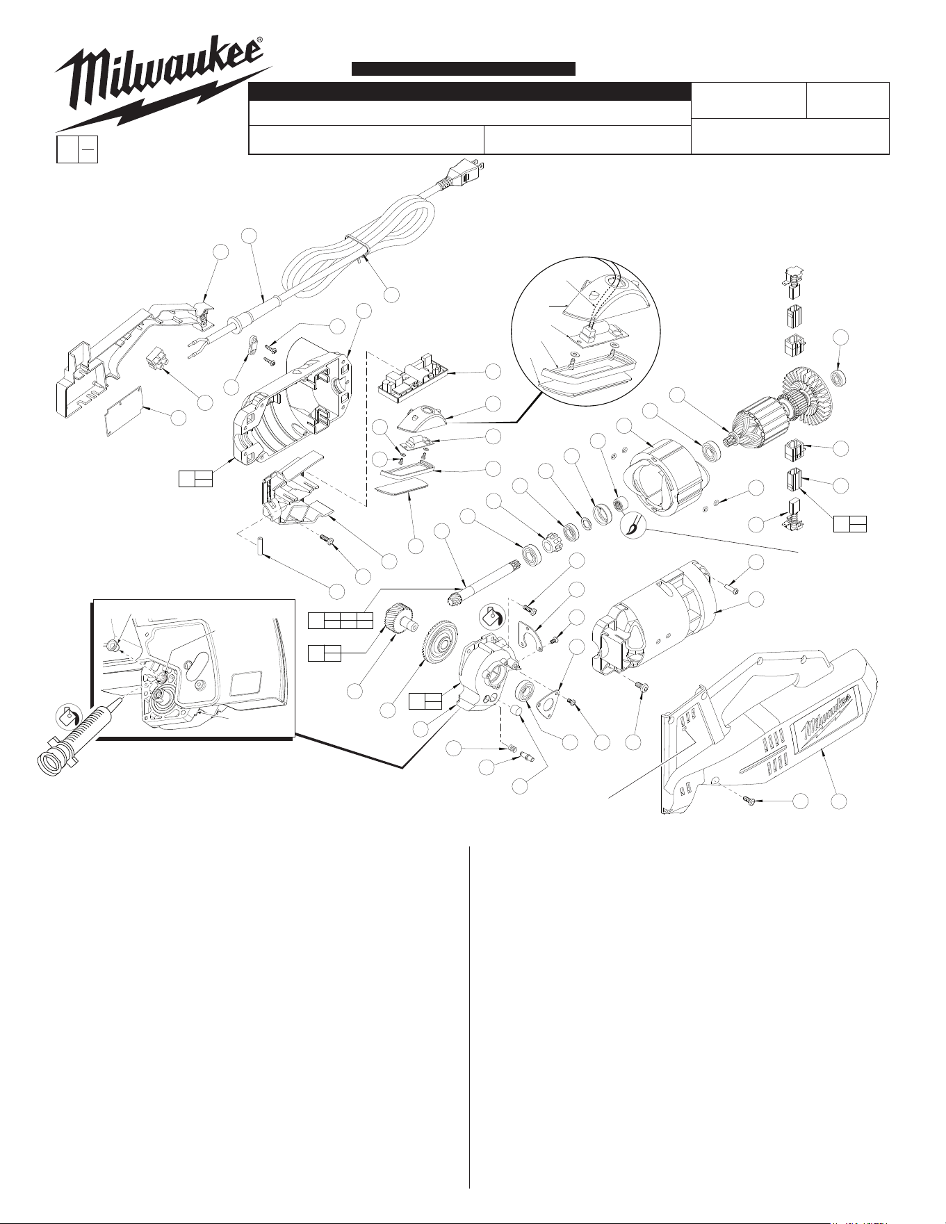
137 02-04-0100 Ball Bearing (1)
138 02-04-0852 Ball Bearing (1)
139 02-04-1212 Ball Bearing (1)
141 02-08-0510 Ball Bearing (2)
142 02-50-2155 Needle Bearing (1)
145 05-73-0155 M6 x 13 Pan Head T-27 Screw (4)
149 05-81-0130 M4 x 8 Pan Head T-20 Screw (6)
150 05-81-0135 M5 x 13 Pan Head T-25 Screw (8)
152 05-81-0155 M5 x 16 Pan Head T-25 Screw (4)
154 05-88-5910 M3.5 x 1.57 x 8mm Pan Hd. T-10 Screw (2)
157 06-82-9220 K40 x 5/8" Slotted T-20 PT Screw (2)
158 06-95-6290 M5 x 2.24 x 18 Slotted T-20 PT Screw (9)
162 16-70-5010 Service Armature Assembly (1)
163 18-70-5000 Service Field (1)
164 22-09-1060 DRO Board (1)
165 22-09-1590 120V Motor Control (1)
166 14-46-1260 Brush Set (Set of 2) (1)
167 --------------- Brush Holder (2)
168 --------------- Brush Tube (2)
170 22-56-0470 Terminal Block (1)
171 22-64-6495 120V Cord Set (1)
172 14-20-6955 LED PCBA (1)
175 23-80-0020 Speed Control Sensor (1)
177 --------------- Gear Case (1)
183 31-17-0155 Cord Clamp (1)
186 --------------- Motor Housing - Left (1)
187 --------------- Motor Housing - Right (1)
00
EXAMPLE:
Component Parts (Small #)
Are Included When Ordering
The Assembly (Large #).
0
FIG. PART NO. DESCRIPTION OF PART NO REQ.
188 31-50-2210 Motor Case Cover (1)
190 31-55-0035 Lower Tray (1)
191 31-55-0040 Upper Tray (1)
194 --------------- Bevel Gear (1)
195 32-60-0081 Bevel Pinion Shaft (1)
197 34-40-0260 O-Ring (4)
199 --------------- Pinion Gear (1)
201 40-50-0390 Spring (1)
207 42-76-0540 Speed Control Collar (1)
208 42-90-0095 Coupling (1)
209 42-96-0080 Bearing Cup (1)
212 43-44-0055 Gasket (1)
218 44-06-0115 Lens (1)
221 44-60-0705 Spindle Lock Pin (1)
223 44-66-0950 Bearing Plate (1)
224 44-66-0955 Bearing Plate (1)
225 44-76-0210 Cord Protector (1)
226 44-79-0041 LEDLightReector (1)
230 45-36-2010 Spacer (1)
243 14-29-0240 Bevel Pinion Shaft Assembly (1)
244 14-29-0250 Gear Service Assembly (1)
246 22-20-0980 Brush Holder Assembly (2)
247 14-30-0910 Gear Case Service Assembly (1)
248 31-50-2206 Motor Housing Assembly (1)
250 45-88-3065 Washer (2)
PAGE 6 OF 8 MOTOR ASSEMBLY
LUBRICATION NOTES
Complete lubrication of the Gearcase #177 can be
achieved by removing black Plug #189 from the front of
the Motor Arm Assembly #242 and inserting the tip of a
largesyringermlyintotheplugopeningandinjecting
1-1/8 oz. Type 'Z' Grease, No. 49-08-7655 into Gearcase.
See the next page for Motor Arm Assembly components.
SERVICE NOTE:
O-Rings#197tin
recesses of Motor Housing
Halves #186 and #187.
Coat inside
#208 with
Type 'U' Grease,
No. 49-08-0150
Use Special Service Tool
No. 61-10-0105 to reset
DRO Board #164. Insert pin into small square hole located in Motor
Case Cover #188. See Wiring Instruction for more detail.
SERVICE NOTES:
Replacement of LED PCBA #172
must be done by removing Lens #218.
«
«
«
«
«= Part number change from
previous service parts list.
«
180 198
205
245
160
152
206
203
219
217
220
182
180
198
150
152
206
150
205
143 159 178
179 215
242
215
229
200
204
155
173
229
185
174 154
181
152
184
159
150
169
147
152
179
153
227
211
234
233
210
146
222
140
189
196
216
150
148
158
3x
2x
2x
2x
2x
2x
2x
2x
4x
2x
161
143
178
226
172
212
218
250
154
Reflector
LED PCBA
Gasket
Lens
Worklights Harness
23-94-8001
176
192
54-40-6926
58-01-6926
B26B or B26C
6955-20
12" SLIDING COMPOUND MITER SAW
REVISED BULLETIN
54-40-6925
BULLETIN NO.
WIRING INSTRUCTION
DATE
SPECIFY CATALOG NO. AND SERIAL NO. WHEN ORDERING PARTS
SERIAL
NUMBER
CATALOG NO.
00
EXAMPLE:
Component Parts (Small #) Are Included
When Ordering The Assembly (Large #).
0
FIG. PART NO. DESCRIPTION OF PART NO REQ.
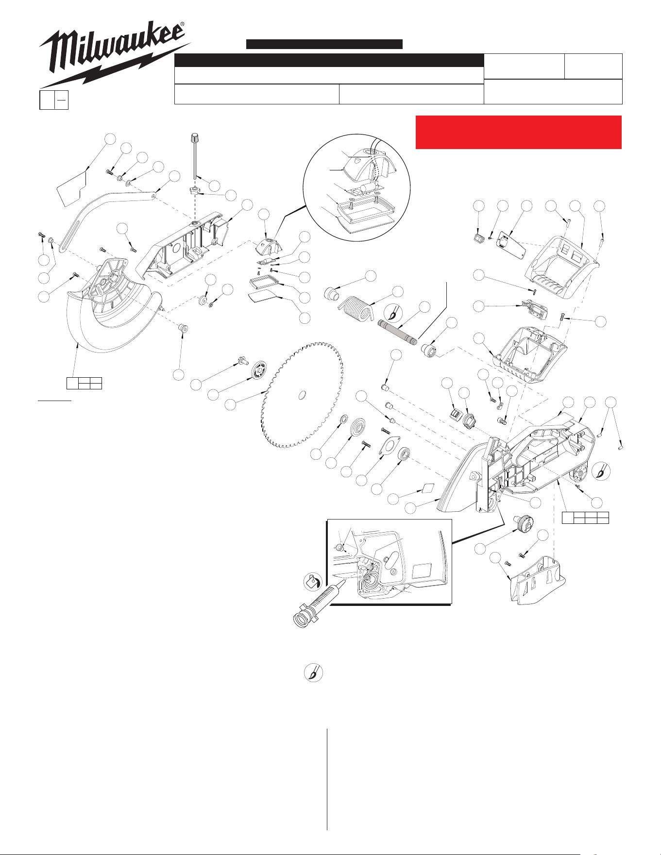
219 44-14-0280 Guard Link (1)
220 44-40-0100 Depth Lock Nut (1)
222 44-66-0945 Bearing Plate (1)
226 44-79-0041 LEDLightReector (1)
227 45-04-0925 Blade Screw (1)
229 45-36-1640 Spring Support Bushing (2)
233 45-36-2025 Blade Spacer (1)
234 42-41-4545 12" Miter Saw Blade (1)
242 14-38-0690 Motor Arm Assembly (1)
245 14-32-0205 Lower Blade Guard Assembly (1)
250 45-88-3065 Washer (2)
SERVICE PARTS
PAGE 7 OF 8 MOTOR ARM ASSY.
PLUG #189
MOTOR ARM
ASSY. #242
OPENING
FOR TIP OF
SYRINGE
LUBRICATION NOTES
Complete lubrication of Gearcase #177 (see previous page) can be achieved
by removing black Plug #189 from the front of the Motor Arm Assembly #242
andinsertingthetipofalargesyringermlyintotheplugopeningand
injecting 1-1/8 oz. Type 'Z' Grease, No. 49-08-7655 into Gearcase.
LUBRICATION NOTES
Fill outer grooves and coat surface of Axle #204 with Type 'Y' Grease,
No. 49-08-5270.
Coat pivot bores of Motor Arm Assembly #242 with Type 'Y' Grease.
DO NOT attempt to disassemble the
Lower Blade Guard Assembly #245.
Tapered end of Axle #204
tobeinsertedrstinto
pivot bores of Motor
Arm Assembly #242.
SERVICE NOTES:
Replacement of LED PCBA #172
must be done by removing Lens #218.
FIG. PART NO. DESCRIPTION OF PART NO REQ.
140 02-04-1700 Ball Bearing (1)
143 --------------- Needle Bearing (1)
146 05-73-0160 M5 x 25 Button Head T-25 Screw (2)
147 05-74-0050 M8 x 16 Socket Head Cap Screw (1)
148 05-80-0500 K40 x 12mm Flat Head T-20 PT Screw (1)
150 05-81-0135 M5 x 13 Pan Head T-25 Screw (7)
152 05-81-0155 M5 x 16 Pan Head T-25 Screw (5)
153 05-86-0645 M6 Set Screw (2)
154 05-88-5910 M3.5 x 1.57 x 8mm Pan Hd T-10 Screw (4)
155 05-88-5915 M3.5 x 1.57 x 12mm Pan Hd T-10 Screw (1)
158 06-95-6290 M5 x 2.24 x 18 Slotted T-20 PT Screw (3)
159 10-20-9105 Guard Plate Label (1)
160 10-20-9110 Arm Warning Label (1)
161 12-20-0095 Service Nameplate (1)
169 22-38-0175 Cable Clamp (1)
172 14-20-6955 LED PCBA (1)
173 23-66-3035 Switch (1)
174 23-66-3040 Rocker Switch (1)
176 23-81-0585 LED Transformer (1)
178 --------------- Upper Guard (1)
179 --------------- Motor Arm (1)
180 31-01-2500 Lower Guard Wheel (2)
181 31-15-2120 Handle Cover (1)
182 31-15-2125 Transformer Cover (1)
184 31-44-2325 Top Handle (1)
185 31-44-2330 Bottom Handle (1)
189 31-53-0235 Plug (1)
192 31-55-0401 Transformer Shield (1)
196 32-75-0080 Spindle Gear (1)
198 34-60-0020 External Retaining Ring (2)
200 40-50-0385 Torsion Spring (1)
203 40-50-3945 Spring washer (1)
204 42-12-0045 Axle (1)
205 42-38-0390 Bumper (1)
206 42-40-0935 Bushing (2)
210 43-34-0865 Inner Blade Flange (1)
211 43-34-0870 Outer Blade Flange (1)
212 43-44-0055 Gasket (1)
215 43-56-0825 BladeDeector (2)
216 43-56-0830 ChipDeector (1)
217 43-98-0290 Depth Adjust Knob (1)
218 44-06-0115 Lens (1)
«
«
«
«
«
«
«
«= Part number change from
previous service parts list.
This page represents all 6955-20 12" Miter saws on This page represents all 6955-20 12" Miter saws on
or before serial break B26C190800001. Page 2 will or before serial break B26C190800001. Page 2 will
represent anything after serial break stated above.represent anything after serial break stated above.
226
172
212
218
250
154
Reflector
LED PCBA
Gasket
Lens
Worklights Harness
23-94-8001
176
192
180 198
205
245
160
152
206
203
219
217
220
182
180
198
150
152
206
150
205
143 159 178
179 215
242
215
229
200
204
155
173
256
252
253
254
229
185
154
181
184
159
150
169
147
152
179
153
227
211
234
233
210
146
222
140
189
196
216
150
148
158
3x
2x
2x
2x
2x
2x
2x
2x
4x
2x
161
143
178
181 184
185
255
174
152
54-40-6926
58-01-6926
B26B or B26C
6955-20
12" SLIDING COMPOUND MITER SAW
REVISED BULLETIN
54-40-6925
BULLETIN NO.
WIRING INSTRUCTION
DATE
SPECIFY CATALOG NO. AND SERIAL NO. WHEN ORDERING PARTS
SERIAL
NUMBER
CATALOG NO.
00
EXAMPLE:
Component Parts (Small #) Are Included
When Ordering The Assembly (Large #).
0
FIG. PART NO. DESCRIPTION OF PART NO REQ.
222 44-66-0945 Bearing Plate (1)
226 44-79-0041 LEDLightReector (1)
227 45-04-0925 Blade Screw (1)
229 45-36-1640 Spring Support Bushing (2)
233 45-36-2025 Blade Spacer (1)
234 42-41-4545 12" Miter Saw Blade (1)
242 14-38-0690 Motor Arm Assembly (1)
245 14-32-0205 Lower Blade Guard Assembly (1)
250 45-88-3065 Washer (2)
252 31-15-0116 Safety Lock (1)
253 40-50-0361 Spring (1)
254 06-66-0116 Pin (1)
255 14-34-0143 Main Handle Kit (1)
256 23-66-0192 Trigger (1)
SERVICE PARTS
PAGE 8 OF 8 MOTOR ARM ASSY.
PLUG #189
MOTOR ARM
ASSY. #242
OPENING
FOR TIP OF
SYRINGE
LUBRICATION NOTES
Complete lubrication of Gearcase #177 (see previous page) can be achieved
by removing black Plug #189 from the front of the Motor Arm Assembly #242
andinsertingthetipofalargesyringermlyintotheplugopeningand
injecting 1-1/8 oz. Type 'Z' Grease, No. 49-08-7655 into Gearcase.
LUBRICATION NOTES
Fill outer grooves and coat surface of Axle #204 with Type 'Y' Grease,
No. 49-08-5270.
Coat pivot bores of Motor Arm Assembly #242 with Type 'Y' Grease.
DO NOT attempt to disassemble the
Lower Blade Guard Assembly #245.
Tapered end of Axle
#204 to be inserted
rstintopivotboresof
Motor Arm Assembly
#242.
SERVICE NOTES:
Replacement of LED PCBA #172
must be done by removing Lens #218.
FIG. PART NO. DESCRIPTION OF PART NO REQ.
140 02-04-1700 Ball Bearing (1)
143 --------------- Needle Bearing (1)
146 05-73-0160 M5 x 25 Button Head T-25 Screw (2)
147 05-74-0050 M8 x 16 Socket Head Cap Screw (1)
148 05-80-0500 K40 x 12mm Flat Head T-20 PT Screw (1)
150 05-81-0135 M5 x 13 Pan Head T-25 Screw (7)
152 05-81-0155 M5 x 16 Pan Head T-25 Screw (5)
153 05-86-0645 M6 Set Screw (2)
154 05-88-5910 M3.5 x 1.57 x 8mm Pan Hd T-10 Screw (4)
155 05-88-5915 M3.5 x 1.57 x 12mm Pan Hd T-10 Screw (1)
158 06-95-6290 M5 x 2.24 x 18 Slotted T-20 PT Screw (3)
159 10-20-9105 Guard Plate Label (1)
160 10-20-9110 Arm Warning Label (1)
161 12-20-0095 Service Nameplate (1)
169 22-38-0175 Cable Clamp (1)
172 14-20-6955 LED PCBA (1)
173 23-66-0172 Switch (1)
174 23-66-3040 Rocker Switch (1)
176 23-81-0585 LED Transformer (1)
178 --------------- Upper Guard (1)
179 --------------- Motor Arm (1)
180 31-01-2500 Lower Guard Wheel (2)
181 31-15-2120 Handle Cover (1)
182 31-15-2125 Transformer Cover (1)
184 31-44-0322 Top Handle (1)
185 31-44-0327 Bottom Handle (1)
189 31-53-0235 Plug (1)
192 31-55-0401 Transformer Shield (1)
196 32-75-0080 Spindle Gear (1)
198 34-60-0020 External Retaining Ring (2)
200 40-50-0385 Torsion Spring (1)
203 40-50-3945 Spring washer (1)
204 42-12-0045 Axle (1)
205 42-38-0390 Bumper (1)
206 42-40-0935 Bushing (2)
210 43-34-0865 Inner Blade Flange (1)
211 43-34-0870 Outer Blade Flange (1)
212 43-44-0055 Gasket (1)
215 43-56-0825 BladeDeector (2)
216 43-56-0830 ChipDeector (1)
217 43-98-0290 Depth Adjust Knob (1)
218 44-06-0115 Lens (1)
219 44-14-0280 Guard Link (1)
220 44-40-0100 Depth Lock Nut (1)
«
«
«
«
«
«
«
«
«
«
«
«
«
«
«
«
«= Part number change from
previous service parts list.
This page will represent anything after This page will represent anything after
serial break B26C190800001.serial break B26C190800001.