54-40-2810
BULLETIN NO.
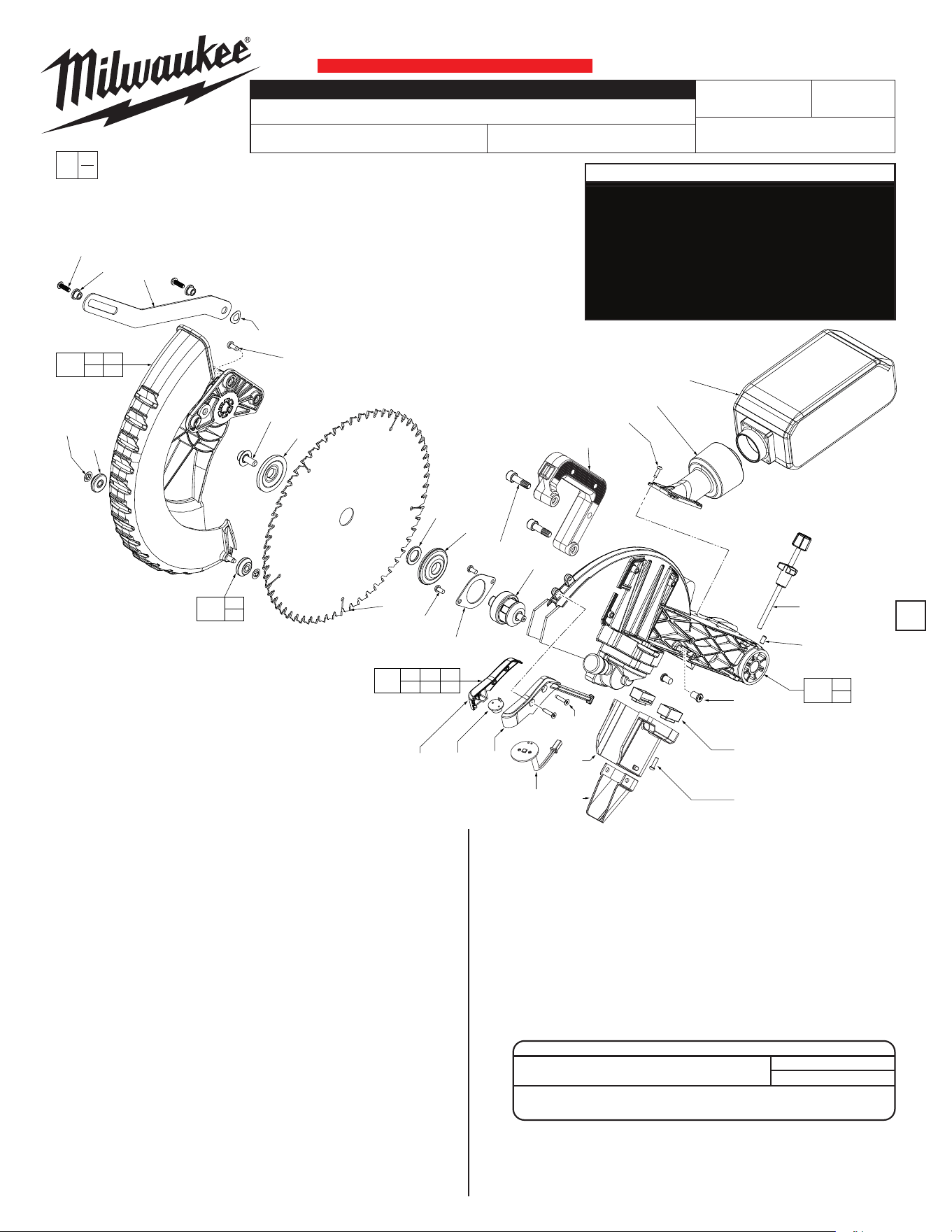
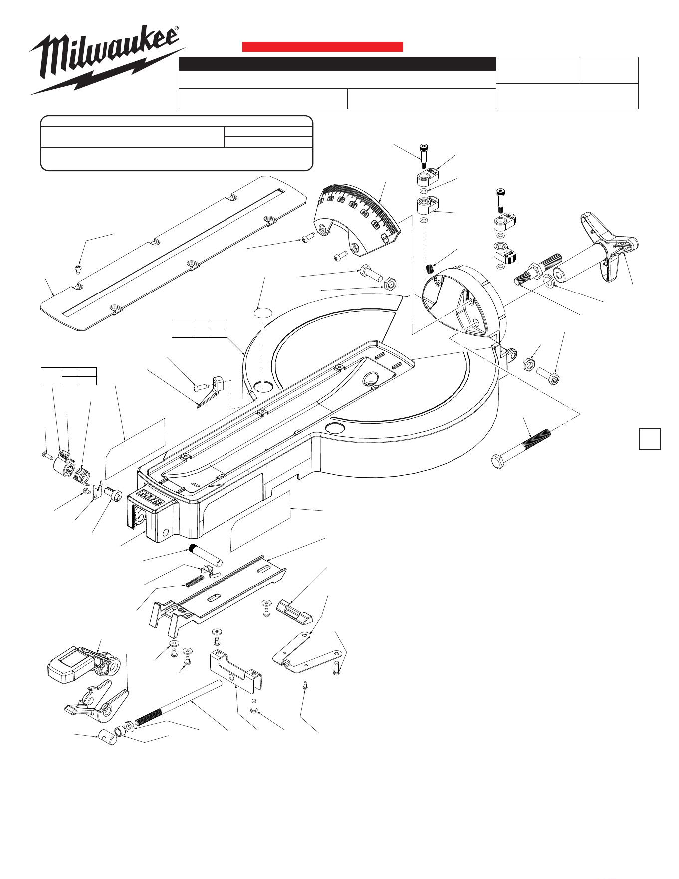
FIG. PART NO. DESCRIPTION OF PART NO. REQ.
1 05-81-0817 M5 x 20mm Pan Hd. T-25 Mach. Scr. (1)
2 42-40-0936 Lower Guard Linkage Bushing (1)
3 44-14-0021 Guard Link Arm (1)
7 --------------- Lower Guard Roller (2)
8 --------------- Lower Guard Retaining Ring (2)
9 05-74-0195 M5 x 10mm Pan Hd. T-25 Mach. Screw (3)
13 45-04-0410 6mm Hex Blade Screw, LH (1)
14 43-34-0016 Outer Blade Flange (1)
15 --------------- 12" Saw Blade (1)
16 45-36-2026 Blade Spacer (1)
17 43-34-0017 Inner Blade Flange (1)
18 05-81-0007 M5 x 12mm Pan Hd. T-25 Mach. Scr. (2)
19 44-66-1071 Bearing Retaining Plate (1)
25 --------------- Shadow Line Housing-Left (1)
26 --------------- Shadow Line Optic (1)
27 --------------- Shadow Line Housing-Right (1)
30 43-56-0810 M8x11mmT-25BladeDeector (2)
35 05-81-0006 Cap Hd. Hex Socket Machine Screw (2)
50 05-88-1210 M4 x 14mm Pan Hd. T-20 Mach. Scr. (3)
54 31-15-0276 Dust Chute Exhaust (1)
66 06-82-0225 M4 x 12mm Pan Hd. T-20 Mach. Scr. (4)
73 44-06-0107 Cover Block (2)
74 42-38-0007 Lower Dust Chute (1)
75 42-38-0285 Dust Boot (1)
00
EXAMPLE:
Component Parts (Small #) Are Included
When Ordering The Assembly (Large #).
0
SERVICE PARTS LIST
MOTOR ARM/LOWER GUARD ASSEMBLIES
K18A
2739-20
M18™ FUEL™ 12" MITER SAW with One-Key™
Apr. 2024
REVISED BULLETIN
WIRING INSTRUCTION
DATE
SPECIFY CATALOG NO. AND SERIAL NO. WHEN ORDERING PARTS
SERIAL
NUMBER
CATALOG NO.
MILWAUKEE TOOL
l
www.milwaukeetool.com
13135 W. LISBON RD., BROOKFIELD, WI 53005
Drwg. 6
Page 1 Motor Arm/Lower Guard Assemblies
Page 2 Motor/Handle/Electronics Assemblies
Page 3 Bevel Arm/Slide Assemblies
Page 4 Table Assembly
Page 5 Base Assembly
Page 6 Lubrication
Page 7 & 8 Wiring Diagram
SERVICE TABLE OF CONTENTS
1
FIG. PART NO. DESCRIPTION OF PART NO. REQ.
81 06-83-0985 Set Screw (1)
102 06-82-0235 M4 x 20mm Flat Hd. ST T-20 Screw (2)
112 14-20-0353 Shadow Light Assembly (1)
155 45-88-7104 Wave Washer (1)
309 14-46-2489 Guard Roller Kit (1)
310 14-32-0161 Lower Guard Assembly (1)
311 14-38-0546 Motor Arm Assembly w/ Needle Bearing (1)
312 14-46-2490 Dado Screw Assembly (1)
313 14-46-0516 Shadow Line Kit (1)
315 38-50-7031 Spindle Assembly (1)
323 42-16-0241 Dust Bag Assembly (1)
324 31-44-2780 Carrying Handle Kit (1)
13
14
15
16
17
18
(2x)
19
315
35
(2x)
8
(2x)
7
(2x)
1
(2x)
2
(2x)
3
155
9
(3x)
324
66
(4x)
54
323
312
81
30
(2x)
73
(2x)
50
(3x)
25 26 27
102
(2x)
74
75
112
25 26 27
102 112
313
7
8
309
7 8
9
310
30
81
311
CRITICAL SCREW TORQUE SPECIFICATIONS
SEAT TORQUE
FIG. PART NO. WHERE USED (kgf-cm) (in-lb)
18 06-81-0007 Brg. Retaining Plate 45-50 39-43
102 06-82-0235 Shadow Line Hsg. 8-10 7-8
54-40-2810
BULLETIN NO.
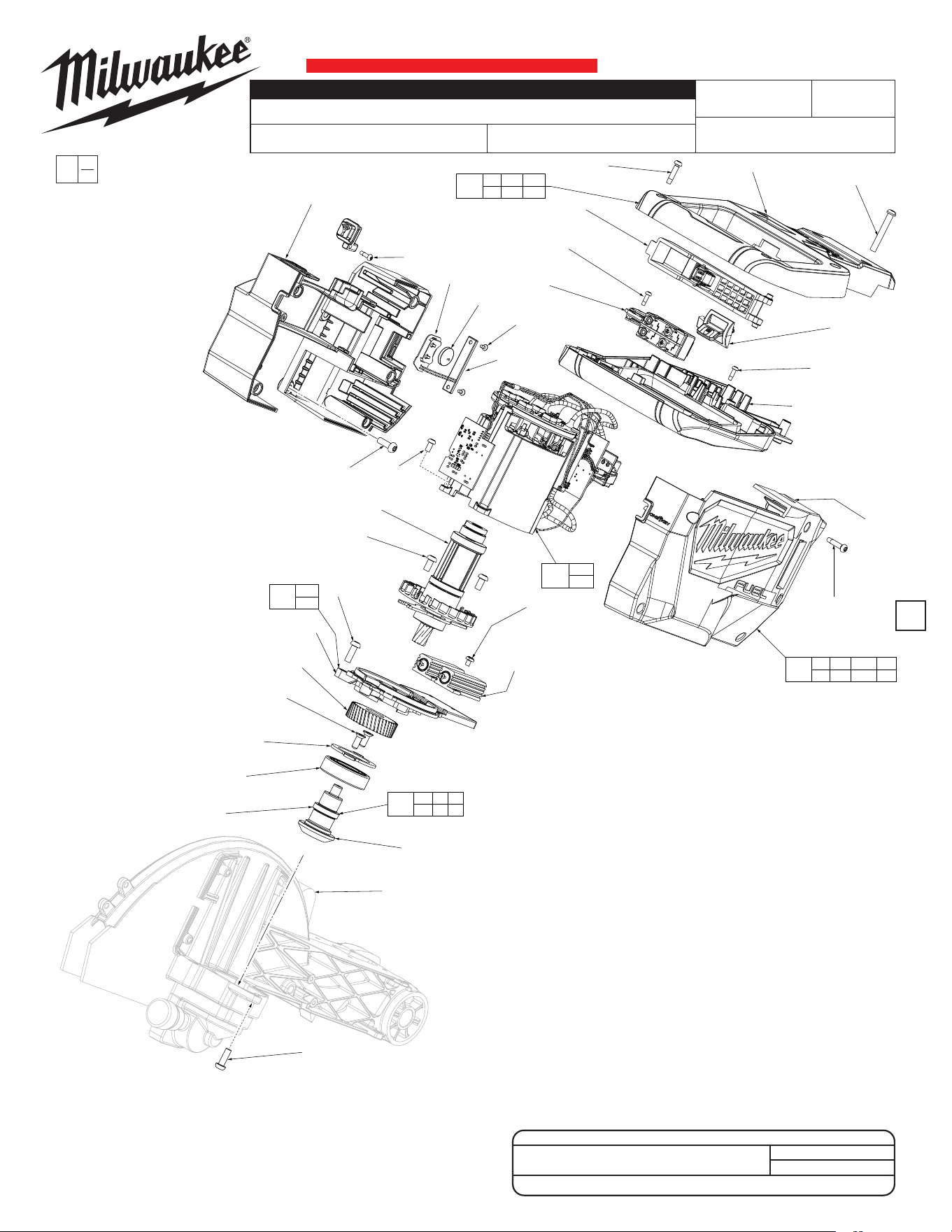
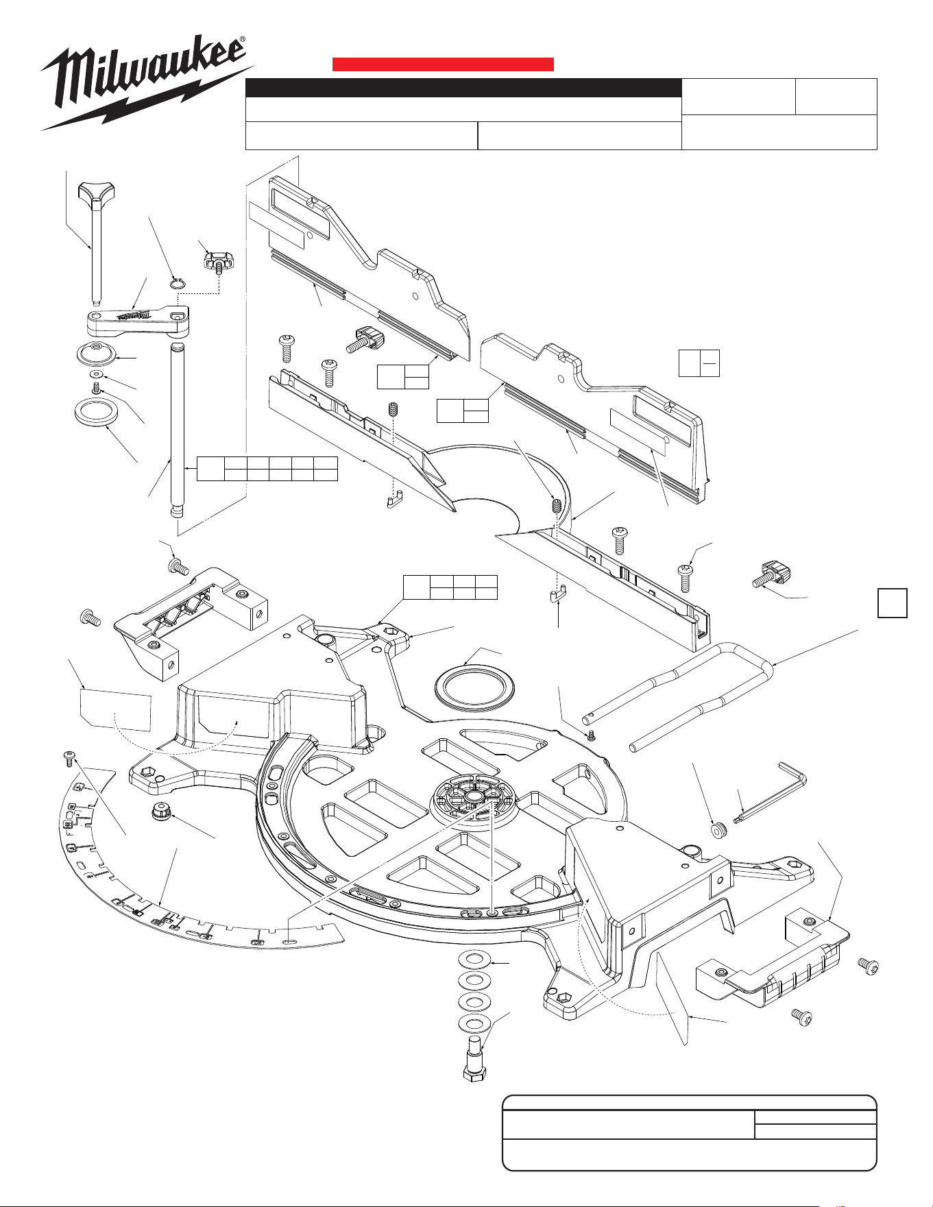
MOTOR/ELECTRONICS/ HANDLE ASSEMBLIES
K18A
2739-20
M18™ FUEL™ 12" MITER SAW with One-Key™
Apr. 2024
REVISED BULLETIN
WIRING INSTRUCTION
DATE
SPECIFY CATALOG NO. AND SERIAL NO. WHEN ORDERING PARTS
SERIAL
NUMBER
CATALOG NO.
SERVICE PARTS LIST
2
FIG. PART NO. DESCRIPTION OF PART NO. REQ.
9a 05-81-0418 M5 x 12mm Pan Hd. T-25 Mach. Scr. (4)
18 05-81-0007 M5 x 12mm Pan Hd. T-25 Mach. Scr. (2)
20 02-04-1807 Ball Bearing (1)
31 --------------- Bevel Pinion (1)
32 36-66-0585 Intermediate Shaft (1)
33 05-81-0008 M3 x 5mm Machine Screw (4)
34 44-66-7025 Intermediate Shaft Plate (1)
FIG. PART NO. DESCRIPTION OF PART NO. REQ.
36 32-40-1955 Intermediate Gear (1)
37 --------------- Diaphragm with Needle Bearing (1)
38 05-81-0812 M5 x 15mm Pan Hd. T-25 Mach. Scr. (3)
48 05-81-0266 M4 x 8mm Pan Hd. T-20 Mach. Screw (4)
58 06-82-0042 M5 x 30mm Pan Hd. Tapt. T-20 Screw (4)
59 06-82-0033 M4 x 18mm Pan Hd. ST T-20 Screw (8)
60 --------------- Top Handle Halve (1)
64 --------------- Bottom Handle Halve (1)
68 06-82-0220 M4 x 12.7mm Pan Hd. T-20 Mach. Scr. (1)
77 23-66-0050 On-OSwitch (1)
78 --------------- Back Cover (1)
79 31-50-0003 Coin Cell Door (1)
80 05-81-1100 M2.6 x 6mm ST Phillips Screw (2)
82 --------------- Outside Cover (1)
120 06-82-0106 M3 x 10mm Pan Hd. ST T-10 Screw (2)
190 22-09-2757 Coin Cell Board Assembly w/ Battery (1)
191 --------------- 3V Coin Cell Battery (CR 2032) (1)
195 06-82-0230 M5 x 10.5mm Flat Hd. T-25 Mach. Scr. (2)
200 --------------- Brake Resistor (2)
311 14-38-0546 Motor Arm Assembly w/ Needle Bearing (1)
314 16-01-0002 Rotor Assembly (1)
316 14-29-2739 Intermediate Gear Assembly (1)
317 31-44-1013 Housing Kit (1)
318 14-13-0031 Diaphragm Assembly w/ Needle Bearing (1)
319 14-20-9004 Electronics Assembly (1)
320 31-44-1006 Main Handle Kit w/ LED Button Assy (1)
321 31-92-0201 Trigger Paddle Assembly (1)
322 --------------- LED Button Assembly (1)
48
(4x)
314
18
(2x)
38
(2x)
37
36
195
(2x)
34
20
32
38
33
(4x)
200
(2x)
31
311
59
(3x)
321
68
77
80
79
191
190
120
78
9a
(4x)
60
58
(4x)
322
64
120
82
59
(5x)
58 59 60
64 120 322
320
200
319
33
37
318
59 78 79
80 82 120
317
20 31 32
34 36
316
9a
00
EXAMPLE:
Component Parts (Small #)
Are Included When Ordering
The Assembly (Large #).
0
CRITICAL SCREW TORQUE SPECIFICATIONS
SEAT TORQUE
FIG. PART NO. WHERE USED (kgf-cm) (in-lb)
18 06-81-0007 Brg. Retaining Plate 30-40 26-34
54-40-2810
BULLETIN NO.
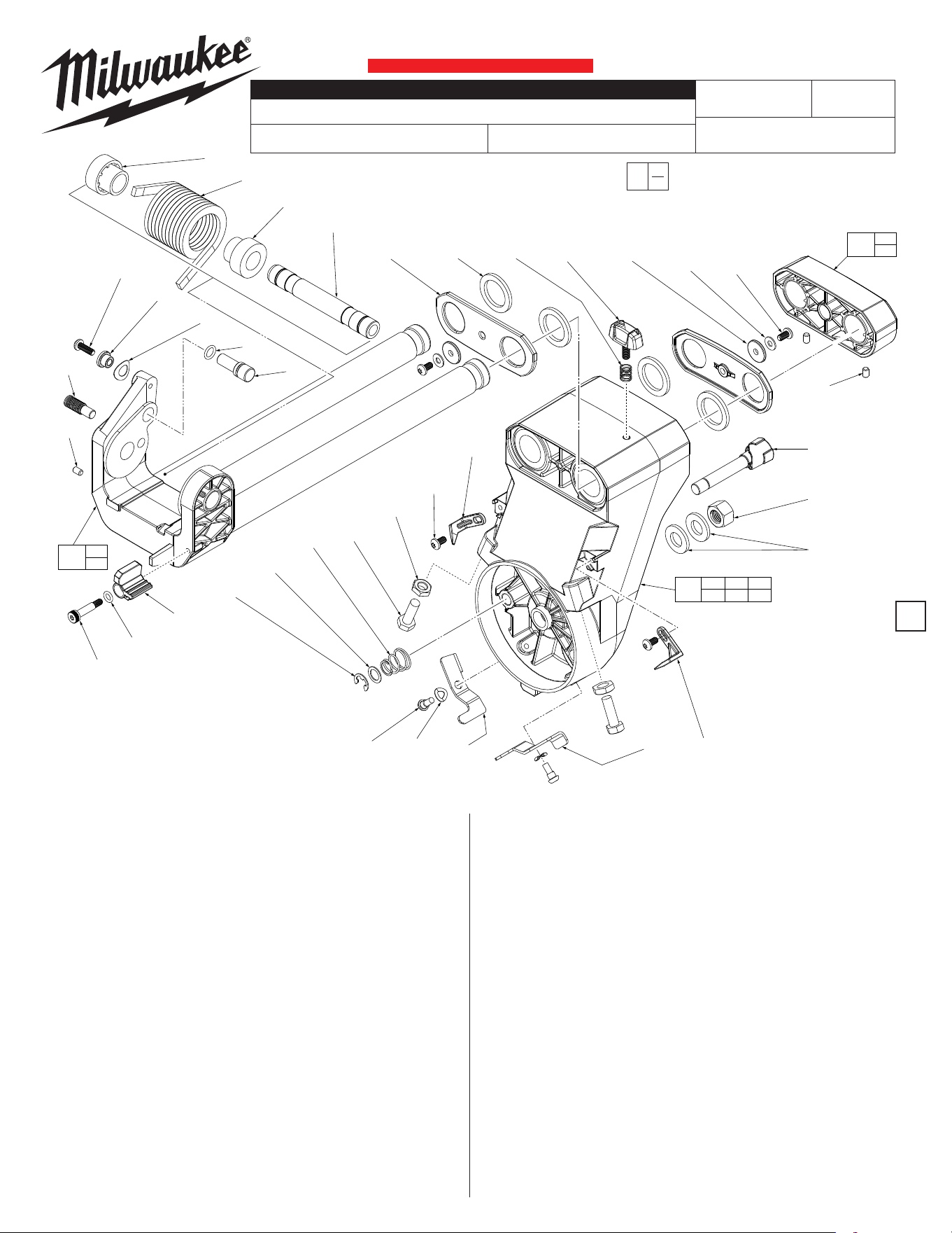
BEVEL ARM / RAIL ASSEMBLIES
K18A
2739-20
M18™ FUEL™ 12" MITER SAW with One-Key™
Apr. 2024
REVISED BULLETIN
WIRING INSTRUCTION
DATE
SPECIFY CATALOG NO. AND SERIAL NO. WHEN ORDERING PARTS
SERIAL
NUMBER
CATALOG NO.
SERVICE PARTS LIST
FIG. PART NO. DESCRIPTION OF PART NO. REQ.
1 05-81-0817 M5 x 20mm Pan Hd. T-25 Mach. Screw (1)
2 42-40-0936 Lower Guard Linkage Bushing (1)
38 05-81-0812 M5 x 15mm Pan Hd. T-25 Mach. Scr. (4)
110 45-06-0023 Felt Seal (4)
113 05-89-0102 M5 x 20mm T-25 Shoulder Screw (1)
116 34-40-0056 O-Ring (1)
118 06-14-0034 M8 x 25mm Hex Hd. Machine Screw (2)
119 05-55-0050 M8 Hex Jam Nut (2)
150 42-40-0192 Pivot Spring Bushing (2)
151 40-50-8899 Axle Spring (1)
152 42-12-0220 Bevel Axle (1)
155 45-88-7104 Wave Washer (1)
157 34-40-0251 O-Ring (1)
158 44-60-0003 Lock Down Pin (1)
159 05-89-0521 Stop Screw (1)
161 45-52-2055 Depth Stop (1)
165 06-83-0011 M5 x 10mm Set Screw (3)
168 45-88-1731 Flat Washer (2)
169 45-88-1701 BuerPad (2)
170 42-92-0006 Bearing Cover (2)
171 44-10-0002 45 Degree Flip-Right (1)
173 34-60-0087 External Retaining Ring (1)
174 45-88-2209 Washer (1)
175 40-50-0143 Conical Spring (1)
176 05-89-0533 Shoulder Screw (2)
3
FIG. PART NO. DESCRIPTION OF PART NO. REQ.
177 45-88-8691 Wave Washer (2)
178 44-10-0003 45 Degree Flip-Left (1)
180 44-72-0032 Bevel Pointer-Right (1)
181 44-72-0031 Bevel Pointer-Left (1)
183 40-50-1017 Spring (1)
184 44-20-0652 Lock Knob (1)
185 45-88-1767 Washer (2)
186 05-59-0145 M12 Hex Nut (1)
187 44-60-0066 Bevel Stop Pin (1)
300 43-70-0076 Arm Hinge/Slide Rail Assembly (1)
301 42-68-1000 Rail Clamp Assembly (1)
302 14-29-0063 Bevel Arm Assembly (1)
00
EXAMPLE:
Component Parts (Small #) Are Included
When Ordering The Assembly (Large #).
0
150
151
150
152
157
158
155
2
1
159
165
113
116
161
181
38
(2x)
119
(2x)
118
(2x)
175
174
173
183 184110
(4x)
170
(2x)
169
(2x)
168
(2x)
38
(2x)
165
(2x)
187
186
185
(2x)
176
(2x)
177
(2x)
178 171 180
165
301
165
300
38 110 168
169 170
302
54-40-2810
BULLETIN NO.
TABLE ASSEMBLY
K18A
2739-20
M18™ FUEL™ 12" MITER SAW with One-Key™
Apr. 2024
REVISED BULLETIN
WIRING INSTRUCTION
DATE
SPECIFY CATALOG NO. AND SERIAL NO. WHEN ORDERING PARTS
SERIAL
NUMBER
CATALOG NO.
SERVICE PARTS LIST
FIG. PART NO. DESCRIPTION OF PART NO. REQ.
38 05-81-0812 M5 x 15mm Pan Hd. T-25 Mach. Scr. (3)
68 06-82-0220 M4 x 12.7mm Pan Hd. T-20 Mach. Scr. (1)
84 43-62-0146 Miter Lock Handle (1)
85 45-72-0100 Detent Release Trigger (1)
86 44-60-0053 Handle Pivot Pin (1)
87 44-60-0063 Lock Rod Pivot Nut (1)
88 45-22-0167 Miter Lock Sleeve (1)
89 05-59-0160 Hex Nut (1)
4
FIG. PART NO. DESCRIPTION OF PART NO. REQ.
90 44-94-2010 Miter Lock Rod (1)
91 05-74-1015 M5 x 15mm Pan Hd. T-25 Mach. Screw (4)
92 05-81-1195 M3 x 8mm Pan Hd. ST T-10 Screw (2)
93 40-50-5705 Miter Detent Spring (1)
94 44-66-1072 Lock Rod Guide (1)
95 44-66-1073 Miter Detent Ramp (1)
96 05-81-1135 M4 x 8mm Pan Hd. T-20 Mach. Screw (10)
97 45-88-2208 Special Washer (4)
98 44-66-1074 Short Adjusted Slider (1)
99 40-50-0086 Spring (1)
103 --------------- Detent Lock Out Knob (1)
104 40-50-0088 Torsion Spring (1)
105 06-82-0230 M4 x 6mm Pan Hd. T-20 Mach. Screw (1)
106 44-66-0282 Retaining Plate (1)
107 --------------- Knob Hub (1)
108 --------------- Table (1)
109 44-72-0116 Miter Pointer (1)
111 44-66-0243 Kerf Plate (1)
113 05-89-0102 M5 x 20mm T-25 Shoulder Screw (2)
114 45-52-2065 22.5 Bevel Stop (2)
115 45-52-2066 33.85 Bevel Stop (2)
116 34-40-0056 O-Ring (4)
117 06-83-0955 Set Screw (1)
118 06-14-0034 M8 x 25mm Hex Hd. Machine Screw (2)
119 05-55-0050 M8 Hex Jam Nut (2)
121 43-82-0147 Bevel Scale (1)
122 45-58-0135 Bevel Stud (1)
123 45-88-1732 Flat Washer (1)
124 43-98-0088 Bevel Knob (1)
125 06-14-0032 M10 x 90mm Hex Hd. Machine Screw (1)
137 44-86-0021 Miter Detent Spring Board (1)
200 10-20-2239 'No Hands' Warning Label (2)
201 10-20-1400
'Miter Detent Override' Warning Label-Left
(1)
202 10-20-1404 'Slide Away' Warning Label-Right (1)
303 28-06-1038 Table Assembly with Labels (1)
304 44-20-0238 Miter Override Lock Assembly (1)
114
(2x)
116
(4x)
115
(2x)
117
124
123
122
118
119
125
38
(2x)
121
118
119
200
(2x)
111
96
(6x)
68
103
104
201
109
38
105
106
107
108
86
137
99
202
98
95
93
91
(2x)
91
(2x)
94
90898887
84
97
(4x)
96
(4x)
85
68 103
104 107
304
108 200
201 202
303
92
(2x)
113
(2x)
CRITICAL SCREW TORQUE SPECIFICATIONS
SEAT TORQUE
FIG. PART NO. WHERE USED (kgf-cm) (in-lb)
91 05-74-1015 Detent Spring 60-70 50-60
122 45-58-0135 Table Assembly 250-300 217-260
54-40-2810
BULLETIN NO.
BASE ASSEMBLY
K18A
2739-20
M18™ FUEL™ 12" MITER SAW
Apr. 2024
REVISED BULLETIN
WIRING INSTRUCTION
DATE
SPECIFY CATALOG NO. AND SERIAL NO. WHEN ORDERING PARTS
SERIAL
NUMBER
CATALOG NO.
SERVICE PARTS LIST
FIG. PART NO. DESCRIPTION OF PART NO. REQ.
100 45-08-0471 Table Bolt (1)
101 40-50-8621 Belleville Spring Washer (4)
126 44-34-0017 Miter Base Foot (4)
127 42-92-1157 Detent Plate Scale (1)
128 05-89-0533 M5 x 13mm Pan Hd. T-25 Shoulder Scr. (5)
129 05-81-0149 M8 x 25mm Pan Hd. T-30 Mach. Screw (8)
130 31-44-0899 Base Handle (2)
131 --------------- Base (1)
132 02-80-0060 Thrust Bearing (1)
133 44-94-0086 Kick Stand (1)
134 22-90-0185 Wrench Grommet (1)
135 49-96-0185 Wrench (1)
136 28-35-0127 Fixed Fence (1)
138 43-98-0041 Fence Lock Knob (2)
139 --------------- Left Sliding Fence (1)
140 --------------- Right Sliding Fence (1)
141 43-98-0043 Vise Knob (1)
142 34-60-0088 Retaining Ring (1)
5
FIG. PART NO. DESCRIPTION OF PART NO. REQ.
143 06-82-0066 Vise Screw (1)
144 42-30-0356 Clamp Body (1)
145 44-94-0008 Vise Rod (1)
146 45-88-1786 Washer (1)
147 05-81-0201 M5 x 10mm Pan Hd. T-25 Mach. Screw (2)
148 45-16-0115 Clamp Shoe (1)
149 45-16-0105 Rubber Shoe (1)
203 10-20-1398 Warning Label - Adjusting Bevel Angle (1)
204 10-20-1399 Warning Label - Spanish and French (1)
205 10-20-2237 Fence Warning Label (2)
208 06-83-0011 Set Screw (2)
209 44-52-0735 Table Support Pad (2)
305 28-06-0001 Base Assembly (1)
306 28-35-0005 Left Fence Assembly (1)
FIG. PART NO. DESCRIPTION OF PART NO. REQ.
307 28-35-0007 Right Fence Assembly (1)
308 42-38-0087 Material Clamp Assembly (1)
00
EXAMPLE:
Component Parts (Small #)
Are Included When Ordering
The Assembly (Large #).
0
138
(2x)
133
129
(4x)
205
(2x)
136
139
205
306
140
205
307
143
142
144
148
146
147
149
145
129
(4x)
141
141 142 143 144 145
146 147 148 149
308
147
134
135
132
126 131 134
203 204
305
131
140
139
130
(2x)
101
(4x)
100
204
203
128
(5x)
126
(4x)
127
208
(2x)
209
(2x)
CRITICAL SCREW TORQUE SPECIFICATIONS
SEAT TORQUE
FIG. PART NO. WHERE USED (kgf-cm) (in-lb)
100 45-08-0471 Base 600-640 520-555
128 05-89-0533 Detent Plate Scale 80-100 69-86
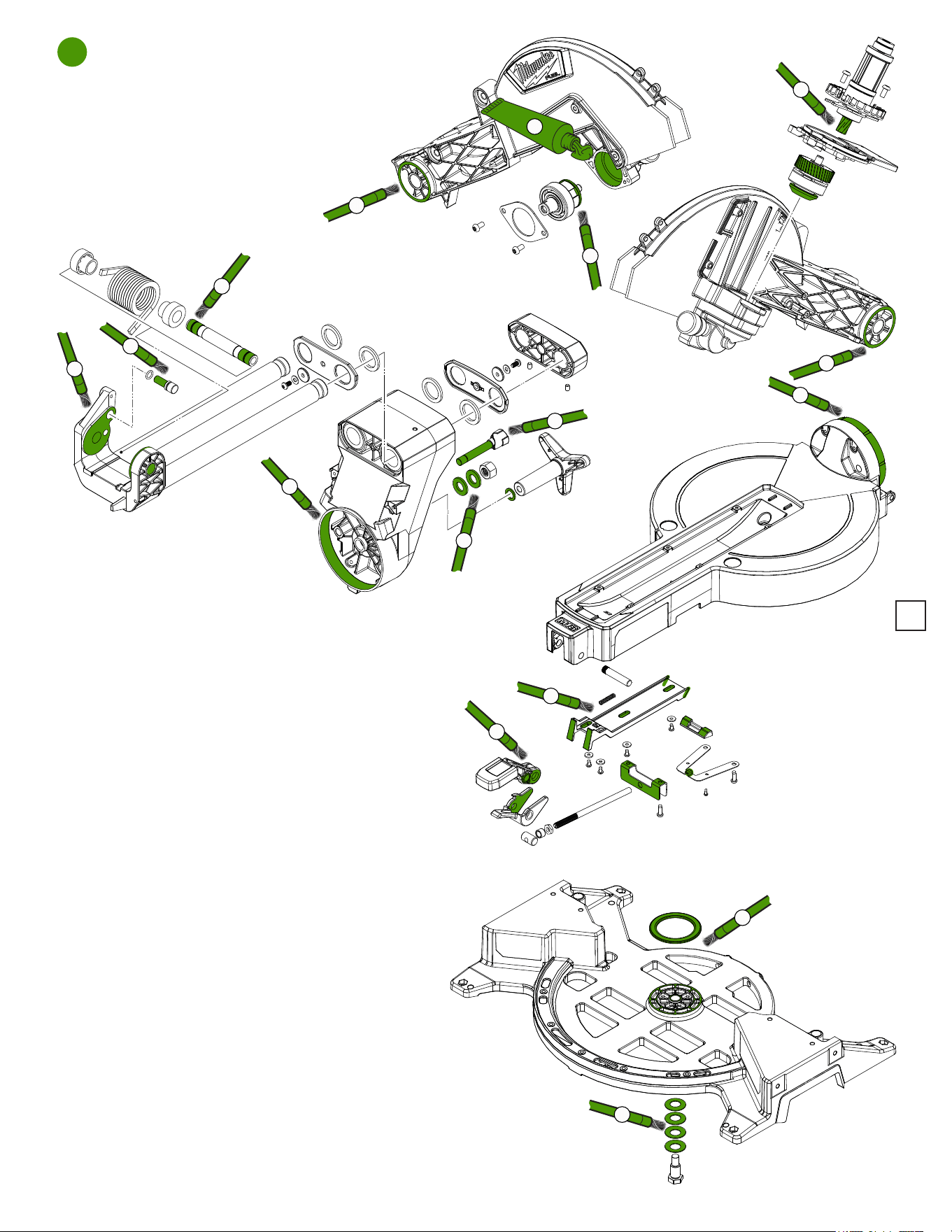
6
LUBRICATION NOTES:
Type ‘Y’ Grease
No. 49-08-5270, 6oz. tube
When servicing the gears or the Gear Case,
90-95% of the old grease must be removed
prior to new grease being added. Clean gear
assemblies with a clean, dry cloth.
1
1
3
4
5
6
7
8
9
10
11
12
13
14
15
2
1. Apply a thin layer of grease to the
outside face (both sides) and both inside
bores at rear of motor arm assembly.
2. Place a liberal amount of grease on rotor
pinion being sure to coat all of the gear teeth.
Place a liberal amount of grease on bevel pinion and
intermediate gear of the intermediate gear assembly
being sure to coat all of the gear teeth.
3. Place a liberal amount of grease to the gear on
the spindle assembly being sure to coat all of the
gear teeth.
4. Place approximately 4.6 grams of grease in gear
cavity of motor arm assembly.
5. Brush surface of bevel axle with grease (both ends)
as shown.
6. Place a thin layer of grease to inside contact
surface and axle bore of arm hinge/slide rail
assembly (both sides).
7. Coat barrel of down lock pin with grease prior
to installation.
8. Place a light film of grease on both sides of
washers.
9. Apply a thin layer of grease to the entire shaft
of bevel stop pin.
10. Coat the inside contact surface of bevel arm with grease.
11. Coat the outside contact surface at the rear of table with grease.
12. Apply grease to the contact points of short adjusted slider, miter detent
ramp lock rod guide and miter detent spring.
13. Coat with grease the friction surfaces of miter lock handle and detent release trigger.
14. Brush both sides of thrust bearing with a heavy layer of grease. Apply grease to the
corresponding surface on the base assembly.
15. Coat all four washers with grease. Be sure to orient washers properly prior to securing
with table bolt.
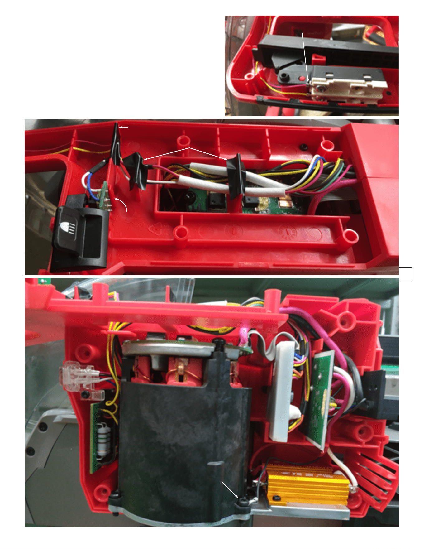
7
As an aid to reassembly, take notice of wire routing and position in wire
guides and traps while dismantling tool.
Be sure all electrical components are rmly and squarely seated in
handle and housing cavities.
Be careful and avoid pinching wires between handle halves and in
housings by tucking wires completely down in traps and channels when
assembling.
Prior to installing the battery, check for proper functionality of switches,
slides and buttons after housings and handles are secure.
Install battery and verify the proper operation of tool.
NOTE:
Updated microswitch design.
Blue and white wires are soldered
and routed on other side of PCBA.
NOTE:
After wires and wire sleeves are routed through wire traps,
place electrical tape over traps (3 places) to aid in keeping
wires secure while installing all electrical components.
Connect wires to
switch as shown.
Ground wire
SEE NEXT PAGE
TO AID IN IDENTIFYING
ELECTRICAL COMPONENTS
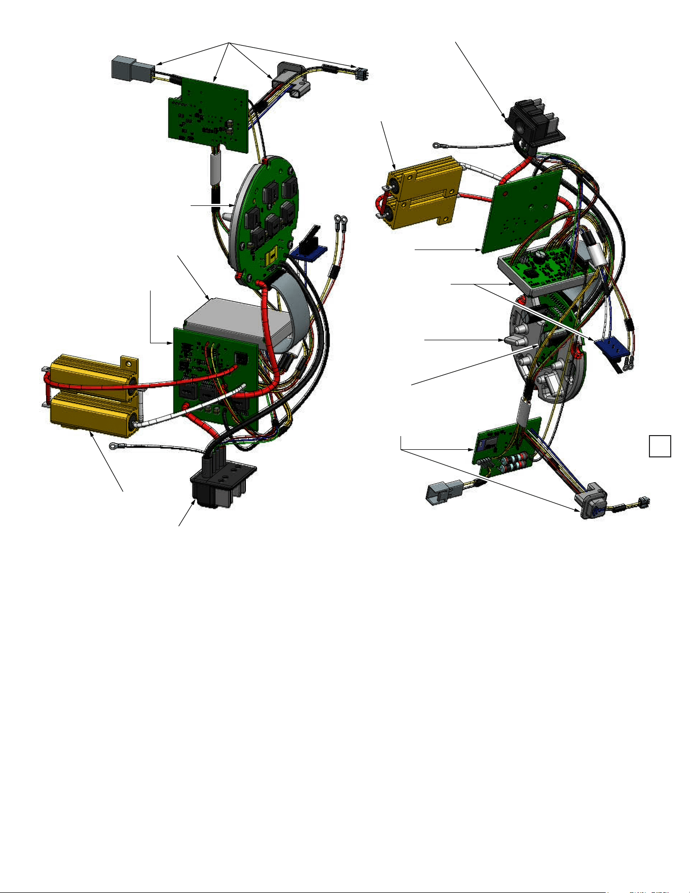
Bluetooth Board and LED Wire Assembly
Power Board
with Heat Sink
Control Board
SSD Board
Resistors
Battery Terminal Block
Battery Terminal Block
Resistors
SSD Board
Control Board and
Microswitch Board Wire
Assembly
Power Board
with Heat Sink
Hall Board
Bluetooth Board and
Microswitch Board
8