Loading ...
Loading ...
Loading ...
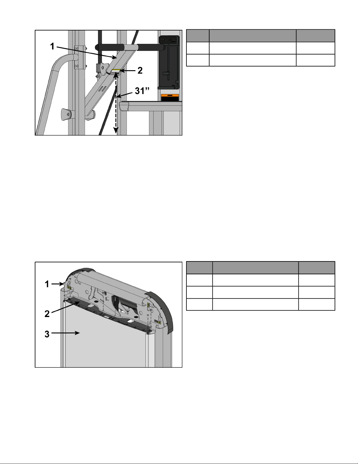
5. Pull belt through clamp until input arm measures 31” from floor.
Measure from floor to lower edge of caution decal (located on foot bar).
Qty.Description
1Foot bar1
1Caution decal2
6. Pull belt tight and secure belt to clamp with the two set screws.
7. Torque set screws 300-350 lb-in.
8. Place weight stack pin in each plate to verify proper installation.
9. Simulate normal operation by lifting top weight up and down with out selecting any resistance.
10. Verify that the belt is moving smoothly and is routed straight from the top pulley bracket to the weight belt
clamp.
11. Turn the Increment Weight Adjusting Knob to select 0 lbs or 0 kg.
Install back panel
Slide back panel down into extrusions.
Install top cover
1. Install screws securing top mount to frame using a Phillips screwdriver.
QtyDescription
6Screw1
1Top mount2
1Back panel3
Page 17 of 26
Loading ...
Loading ...
Loading ...