Loading ...
Loading ...
Loading ...
14
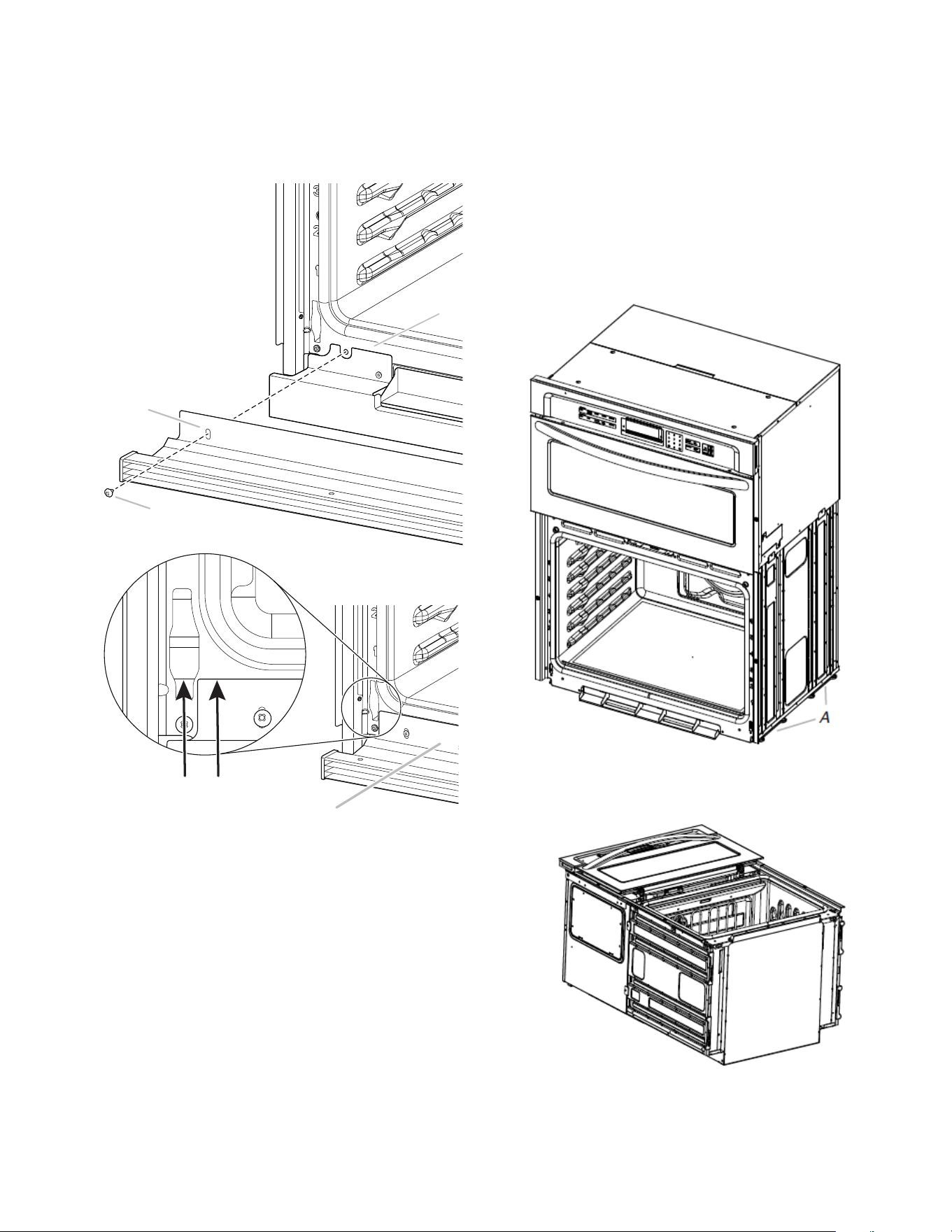
6. After the bottom vent shield is installed.
� Align the bottom vent trim tab (B) with the oven frame (A)
as shown.
� Using one #8-18 x 3/8" (9.5 mm) screw (C) on each side of
the trim tab (B), align the top edge of the bottom vent trim
tab (E) with the hinge receiver edge (D) as shown.
� Fasten the bottom vent trim securely to the oven frame (A).
D
B
E
A. Oven frame
B. Trim tab
C. #8-18 x 3/8" (9.5 mm)
screw
D. Hinge receiver edge
E. Bottom Vent Trim Tab top
edge
7. Replace the oven racks.
8. Replace the oven door. See the “Replace Oven Door(s)”
section.
9. Check that the door is free to open and close. If it is not,
repeat the removal and installation procedures. See the
“Prepare Built-In Oven” section.
10. Repeat for lower oven door.
IMPORTANT: For proper oven operation, check that the gap
between bottom trim of the door and bottom vent trim is at least
1/4" (6.4 mm).
11. Reconnect power.
12. The display panel will light briefly, and “PF” may appear in the
display.
13. If the display panel does not light, refer the Warranty.
14. If F9E0 error code is encountered upon powering up the unit,
the appliance is wired incorrectly at the Junction Box or
Electrical Panel. Contact a qualified electrician to verify the
home electrical supply and the hardwire connection at the
Junction Box or Electrical Panel (See the Electrical
Connection Options section).
Positioning Oven Feet
The oven feet need to be installed to allow the microwave/oven
combination to be installed in a Flush Installation or in Standard
Installations where the cutout height is 42
1
/
2
" (107.9 cm) or more.
NOTE: Do not remove the spacers.
A. Spacers
1. Using 2 or more people, place the on its back on a covered
surface.
A
C
B
Loading ...
Loading ...
Loading ...