
ASSEMBLY MANUAL / OWNER’S MANUAL

2
TABLE OF CONTENTS
Important Safety Instructions 3
Safety Warning Labels / Serial Number 5
Specications 6
BeforeAssembly 6
Parts 7
Hardware 8
Tools 8
Assembly 9
Moving the Machine 15
Leveling the Machine 15
Features 16
Console Features 17
Remote Heart Rate Monitor 19
Auto-Calibration 20
Operations 21
Adjustments 21
Using the Machine 21
Locking the Fan Assembly / Storage 22
Power Up / Idle Mode 22
Manual Workout 22
Interval Workouts 23
Target Workouts 23
Heart Rate Zones 25
Pausing / Results Mode 25
ConsoleServiceMode 26
Maintenance 27
Replacing the Console Batteries 28
Maintenance Parts 29
Troubleshooting 30
To validate warranty support, keep the original proof of purchase and record the following information:
Serial Number __________________________
Date of Purchase ____________________
To register your product warranty, contact your local distributor.
For details regarding product warranty or if you have questions or problems with your product, please contact
yourlocalSchwinndistributor.Tondyourlocaldistributor,goto:www.nautilusinternational.com
Nautilus, Inc., www.nautilusinternational.com | Nautilus, Inc., 18225 NE Riverside Parkway, Portland, OR 97230 USA | Printed
in China | © 2015 Nautilus, Inc. | ® indicates trademarks registered in the United States. These marks may be registered in other
nationsorotherwiseprotectedbycommonlaw.Schwinn,theSchwinnQualitylogo,AirDyne,Nautilus,Bowex,andUniversalare
trademarks owned by or licensed to Nautilus, Inc. Polar® and OwnCode® are registered trademarks of their owner.
ORIGINAL MANUAL - ENGLISH VERSION ONLY

3
IMPORTANT SAFETY INSTRUCTIONS
When using an electrical appliance, basic precautions should always be followed, including the following:
This icon means a potentially hazardous situation which, if not avoided, could result in death or serious
injury.
Obey the following warnings:
Read and understand all warnings on this machine.
Carefully read and understand the Assembly instructions. Read and understand the complete
Manual. Keep the Manual for future reference.
To decrease the risk of burns, electric shock, or injury to persons, read and understand the
complete Owner’s Manual. Failure to follow these guidelines can cause a serious or possibly fatal
electrical shock or other serious injury.
• Keep bystanders and children away from the product you are assembling at all times.
• Donotinstallthebatteriesintothemachineuntilthetimespeciedintheassemblymanual.Donotconnectthe
optional power supply to the machine until instructed to do so.
• The machine should never be left unattended when plugged in. Unplug from outlet when not in use, and before putting
on or taking off parts.
• Beforeeachuse,examinethismachineforloosepartsorsignsofwear.Donotuseiffoundinthiscondition.Monitor
the Pedals and Crank Arms closely. Contact your local distributor for repair information.
• Not intended for use by persons with medical conditions where those conditions may impact the safe operation of the
machine or pose a risk of injury to the user
• Do not drop or put objects into any opening of the machine.
• Do not assemble this machine outdoors or in a wet or moist location.
• Makesureassemblyisdoneinanappropriateworkspaceawayfromfoottrafcandexposuretobystanders.
• Some components of the machine can be heavy or awkward. Use a second person when doing the assembly steps
involving these parts. Do not do steps that involve heavy lifting or awkward movements on your own.
• Set up this machine on a solid, level, horizontal surface.
• Do not try to change the design or functionality of this machine. This could compromise the safety of this machine and
will void the warranty.
• If replacement parts are necessary use only genuine replacement parts and hardware supplied by Nautilus. Failure
to use genuine replacement parts can cause a risk to users, keep the machine from operating correctly and void the
warranty.
• Do not use or put the machine into service until the machine has been fully assembled and inspected for correct
performance in accordance with the Manual.
• Use this machine only for its intended use as described in this manual. Do not use attachments not recommended by
the manufacturer.
• Do all assembly steps in the sequence given. Incorrect assembly can lead to injury or incorrect function.
• SAVE THESE INSTRUCTIONS.

4
Before using this equipment, obey the following warnings:
Read and understand the complete Manual. Keep the Manual for future reference.
Read and understand all warnings on this machine. If at any time the Warning stickers become loose,
unreadable or dislodged, contact your local distributor for replacement stickers.
To reduce the risk of electrical shock or unsupervised usage of the equipment, always unplug the
power cord from the wall outlet and the machine and wait 5 minutes before cleaning, maintaining or
repairing the machine. Place the power cord in a secure location.
• Children must not be let on or near to this machine. Moving parts and other features of the machine can be dangerous
to children.
• Not intended for use by anyone under 14 years of age.
• Consultaphysicianbeforeyoustartanexerciseprogram.Stopexercisingifyoufeelpainortightnessinyour
chest, become short of breath, or feel faint. Contact your doctor before you use the machine again. Use the values
calculated or measured by the machine’s computer for reference purposes only.
• Beforeeachuse,examinethismachinefordamagetopowercord,powerreceptacle,loosepartsorsignsofwear.Do
not use if found in this condition. Monitor the Pedals and Crank Arms closely. Contact your local distributor for repair
information.
• Maximumuserweightlimit:159kg(350lbs.).Donotuseifyouareoverthisweight.
• Donotwearlooseclothingorjewelry.Thismachinecontainsmovingparts.Donotputngersorotherobjectsinto
movingpartsoftheexerciseequipment.
• Always wear rubber soled athletic shoes when you use this machine. Do not use the machine with bare feet or only
wearing socks.
• Set up and operate this machine on a solid, level, horizontal surface.
• Do not step off the machine until the Pedals have fully stopped.
• Make the Pedals stable before you step on them. Use caution when you step on and off the machine.
• Disconnect all power before servicing this machine.
• Do not operate this machine outdoors or in moist or wet locations.
• Keepatleast0.6m(24”)oneachsideofthemachineclear.Thisistherecommendedsafedistanceforaccessand
passage around and emergency dismounts from the machine. Keep third parties out of this space when machine is in
use.
• Donotoverexertyourselfduringexercise.Operatethemachineinthemannerdescribedinthismanual.
• Perform all regular and periodic maintenance procedures recommended in the Owner’s Manual.
• Do not drop or put objects into any opening of the machine.
• Correctly adjust and safely engage all Positional Adjustment Devices. Make sure that the Adjustment Devices do not
hit the user.
• Keep the Pedals clean and dry.
• Exerciseonthismachinerequirescoordinationandbalance.Besuretoanticipatethatchangesinspeedand
resistance level can occur during workouts, and be attentive in order to avoid loss of balance and possible injury.
• A machine should never be left unattended when plugged in. Unplug from outlet when not in use, and before putting
on or taking off parts.
• Keep batteries away from heat source and hot surfaces.
• Donotmixoldandnewbatteries.
• Donotmixalkaline,standard(carbon-zinc),orrechargeable(Ni-Cd,Ni-MH,etc)batteries.
• Donottrytochargenon-rechargeablebatteries.Removeexhaustedbatteriesanddisposeofthemsafely.
• Remove rechargeable batteries from the machine before recharging them.
• Do not short-circuit the supply terminals on the batteries.
5
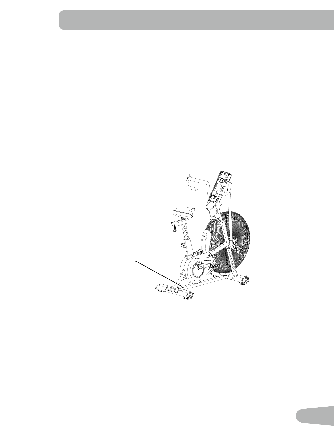
SAFETY WARNING LABELS AND SERIAL NUMBER
Product specification
Serial number
Safety Warning Labels and Serial Number
• For safe storage of the machine, remove the batteries and install the Transport and Immobilization Strap to secure the
Resistance Fan. Place the machine in a secure location away from children and pets.
• When the machine is put in a Commercial environment, it can only be used in areas where access and control of the
machine are managed and supervised by approved staff. The degree of management depends among other things on
thespecicsettinginwhichthemachineisplaced,securityofthatenvironment,andfamiliarityoftheuserswiththe
equipment. Because others will have used the machine previously, make sure the seat, pedals and handlebars are
correctly adjusted, tightened and secured.
• Thisapplianceisnotintendedforusebypersons(includingchildren)withreducedphysical,sensoryormental
capabilities,orlackofexperienceandknowledge,unlesstheyhavebeengivensupervisionorinstructionconcerning
use of the appliance by a person responsible for their safety.
• This bike cannot stop the Pedals independently of the Resistance Fan. Reduce the pace to slow the Resistance Fan
and Pedals to a stop. Do not dismount the bike until the Pedals have come to a complete stop. Be aware that the
moving Pedals can strike the backs of the legs.
6
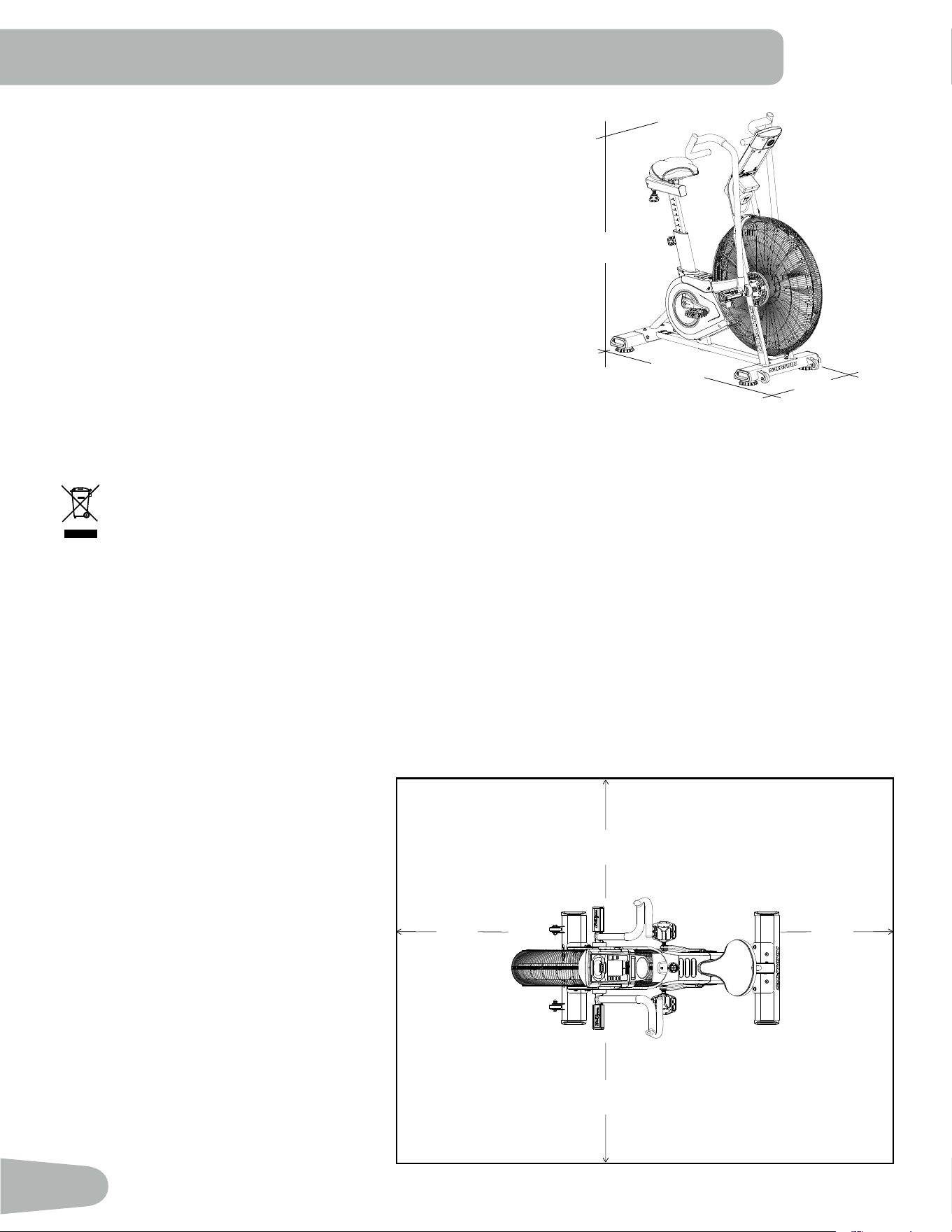
SPECIFICATIONS
Before Assembly
Select the area where you are going to set up and operate your machine. For safe operation, the location must be on a
hard,levelsurface.Allowaworkoutareaofaminimum1.9m(74.5”)x2.6m(101”).
Basic Assembly Tips
Follow these basic points when you assemble your machine:
• Read and understand the “Important
SafetyInstructions”beforeassembly.
• Collect all the pieces necessary for
each assembly step.
• Using the recommended wrenches,
turn the bolts and nuts to the right
(clockwise)totighten,andtheleft
(counterclockwise)toloosen,unless
instructed otherwise.
• When attaching 2 pieces, lightly lift
and look through the bolt holes to help
insert the bolt through the holes.
• The assembly requires 2 people.
Maximum User Weight: 159kg(350lbs.)
Total Surface Area (footprint) of equipment: 9059 cm
2
(1405in
2
)
Machine Weight: 51.3kg(113lbs.)
Power Requirements:
InputVoltage: 100-240VAC,50/60Hz,0.4A
Output Voltage: 9V DC , 1.5A
OptionalBatteries: 2DBatteries(LR20)–notincluded
134.6 cm
53”
134.6 cm
53”
67.3 cm
26.5”
DO NOT dispose of this product as refuse. This product is to be recycled. For proper disposal of this product,
please follow the prescribed methods at an approved waste center.
0.6m
24”
1.9m
74.5”
2.6m
101”
0.6m
24”
0.6m
24”
0.6m
24”
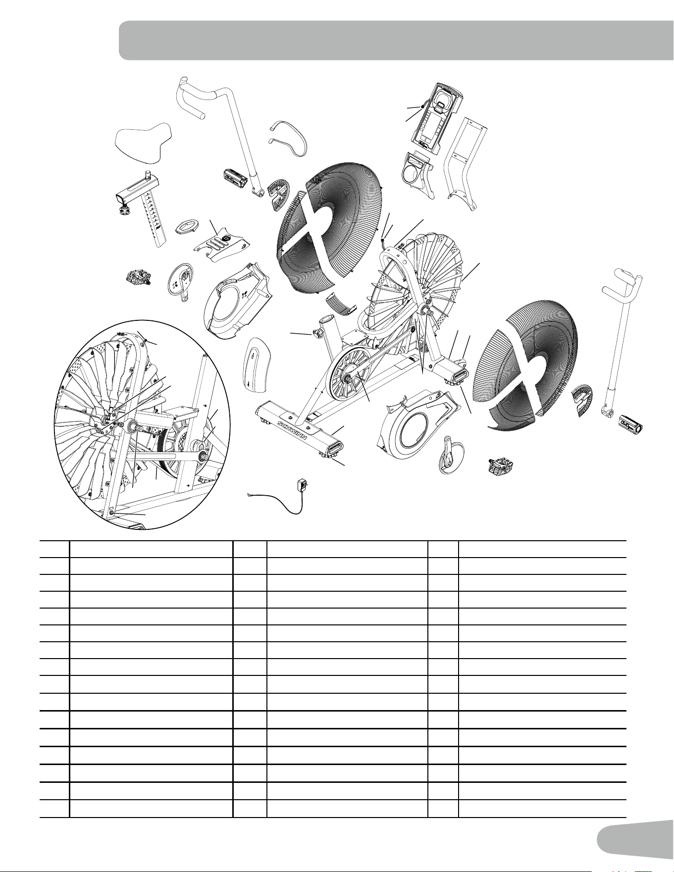
7
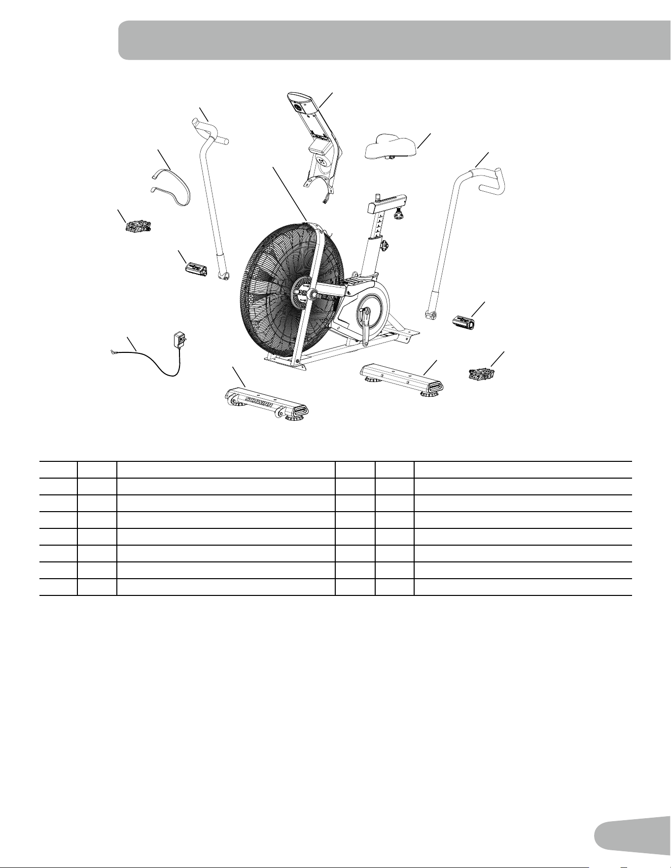
PARTS
1
2
3
4
5
6
7
8
9
10
12
11
13
Adecalhasbeenappliedtoallright(“R”)andleft(“L”)partstoassistwithassembly.
Item Qty Description Item Qty Description
1 1 Frame Assembly 8 1 Stabilizer, Front
2 1 Console / Mast Assembly 9 1 Foot Peg, Right
3 1 Seat 10 1 Pedal, Right
4 1 Handlebar, Left 11 1 Handlebar, Right
5 1 Foot Peg, Left 12 1 Strap, Transport and Immobilization
6 1 Pedal, Left 13 1 AC Power Adapter
7 1 Stabilizer, Rear
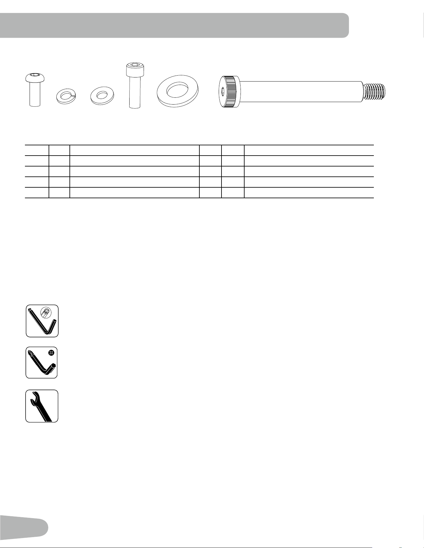
8
Item Qty Description Item Qty Description
A 12 ButtonHeadHexScrew,M8x16 E 2 FlatWasher,M16
B 12 Lock Washer, M8 F 2 ShoulderScrew,M12x100
C 12 Flat Washer, M8
D 4 SocketHeadCapScrew,M8x25
Note: Select pieces of Hardware have been provided as spares on the Hardware Card. Be aware that there may be
remaining Hardware after the proper assembly of your machine.
HARDWARE / TOOLS
A B C D E F
Tools
Included
6mm
#2
6mm
13 / 15 mm
9
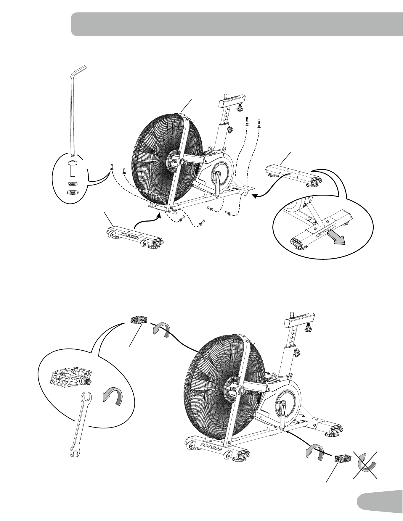
1. Attach Stabilizers to Frame Assembly
ASSEMBLY
10 (R)
6 (L)
1
7
8
6mm
X8
A
B
C
2. Attach Pedals to Frame Assembly
Note: The Left Pedal is reverse-threaded. Be sure to attach Pedals on the proper side of the Bike. Orientation is based
fromaseatedpositiononthebike.TheLeftPedalhasan“L”,theRightPedalan“R”.
10
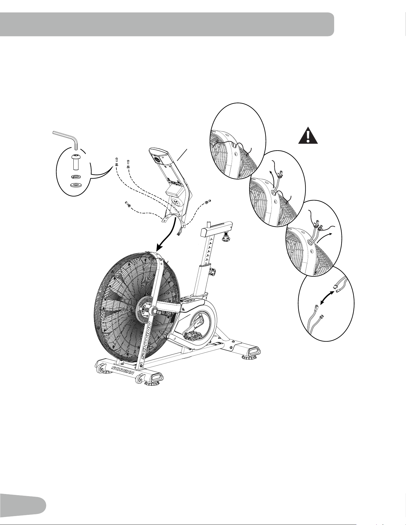
3. Connect Cables and Attach the Console/Mast Assembly to Frame Assembly
NOTICE: Do not crimp the cables.
6mm
X4
A
B
C
2
11
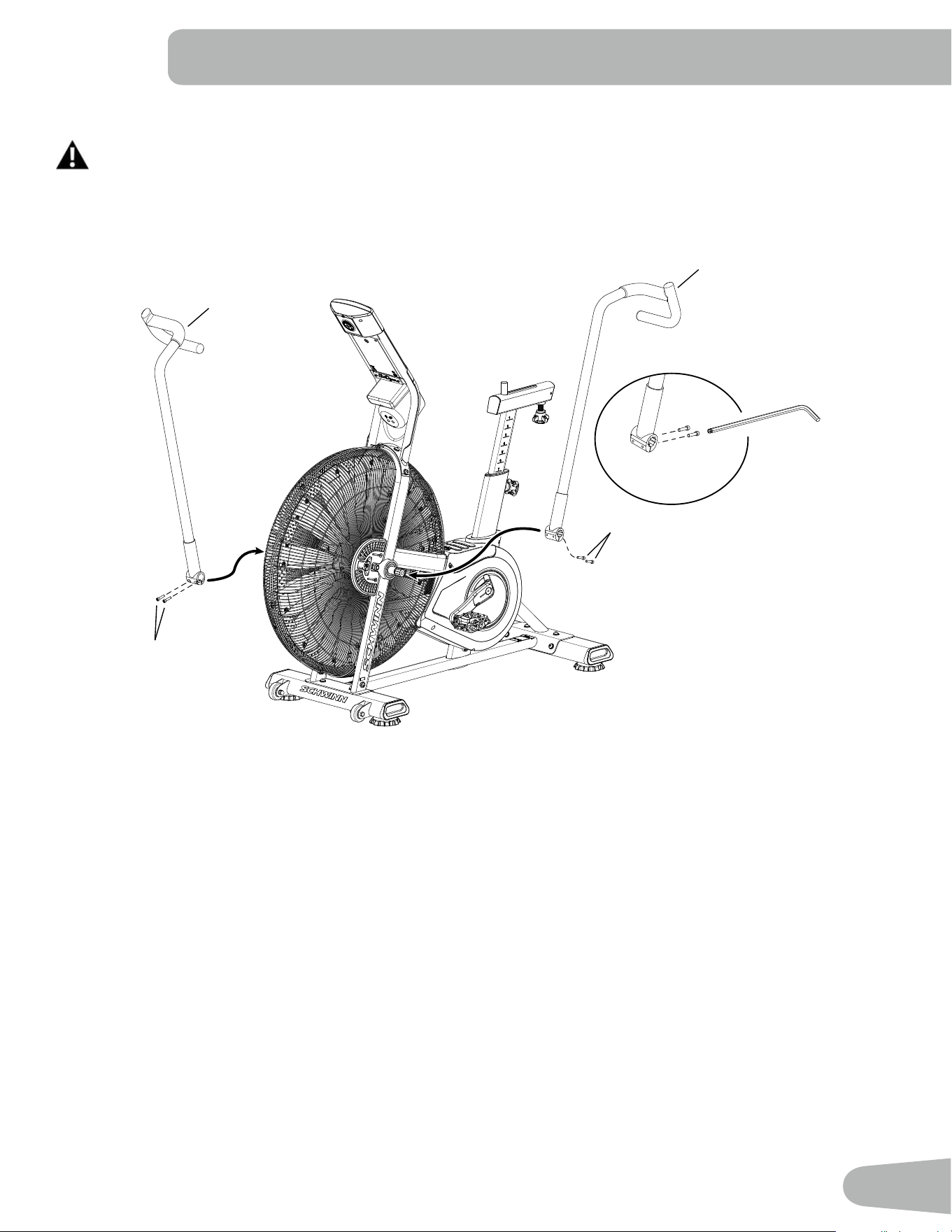
4. Attach Handlebar Arms to Frame Assembly
Fully tighten hardware. Make sure the Handlebar Arms are secure before you exercise. If a torque wrench is
available, tighten bolts to 40 N
.
m.
11
4
D
D
D
4
6mm
12
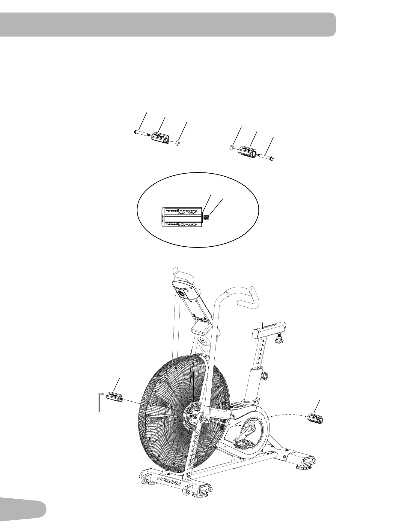
5. Assemble Foot Pegs and Hardware, and Attach Foot Pegs to Frame Assembly
NOTICE: PushtheShoulderScrew(F)completelythroughtheFootPeg,andpresstheWasher(E)tightlyontotheendof
theFootPeg.BesuretheWasherdoesnottouchthescrewthreads(F1).DonotlettheWasherfallofftheFoot
Peg during installation.
E
6mm
9
5
5
9
F
F
E
E
E
F1
13
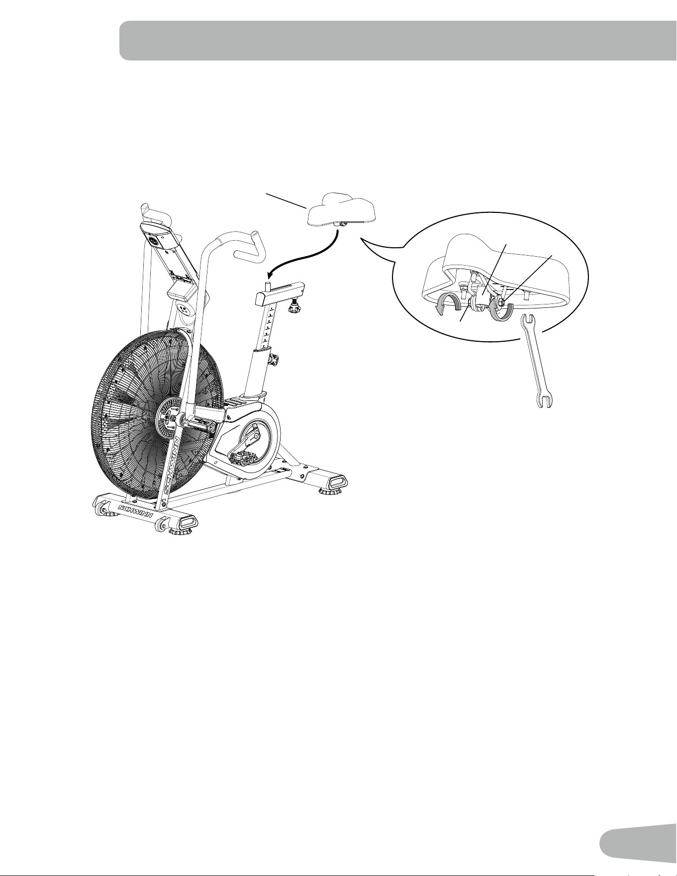
6. Attach Seat to Seat Post
NOTICE: BesuretheSeatisstraight.Tightenbothnuts(3b)ontheSeatbracket(3a)toholdtheSeatinposition.
3a
3b
3b
3
14
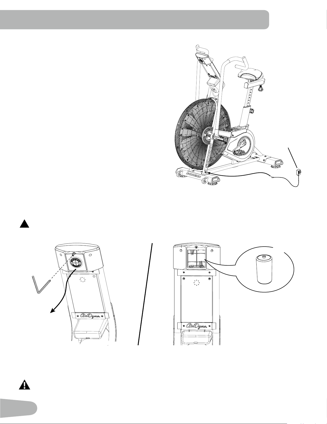
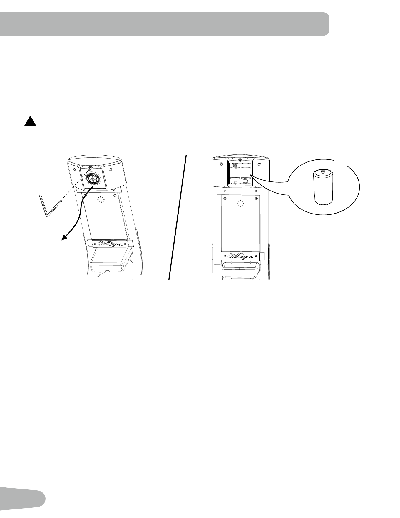
Optional Batteries in Console
Note:Toopenthebatterybay,loosenthepreinstalledscrewinthecover.TheconsoleusesDsizebatteries(LR20).Make
surethatthebatteriespointinthedirectionofthe+/–indicatorsinthebatterybay.Ifyouuserechargeablebatteries,
the power adapter will not recharge the batteries.
!
Do not mix old and new batteries.
Do not mix alkaline, standard (carbon-zinc), or rechargeable (Ni-Cd, Ni-MH, etc) batteries.
7. Connect Power Adapter
The console for your machine can operate on battery power
or AC power. If batteries and the Power Adapter are installed,
the console will use the Power Adapter to operate.
Note: If you use rechargeable batteries, the Power Adapter
will not recharge the batteries.
After the machine is fully assembled, connect the Power
Adaptor to the Power Connector and the wall outlet.
NOTICE: If you use a power adapter for your machine, make
sure that the cord stays clear of the path of the
pedals.
NOTICE: It is recommended to remove batteries when
they are not used, to avoid damage from battery
corrosion.
8. Final Inspection
Inspect your machine to ensure that all hardware is tight and components are properly assembled.
Be sure to record the serial number in the field provided at the front of this manual.
Do not use or put the machine into service until the machine has been fully assembled and inspected for
correct performance in accordance with the Owner’s Manual.
X2
+
–
13
15
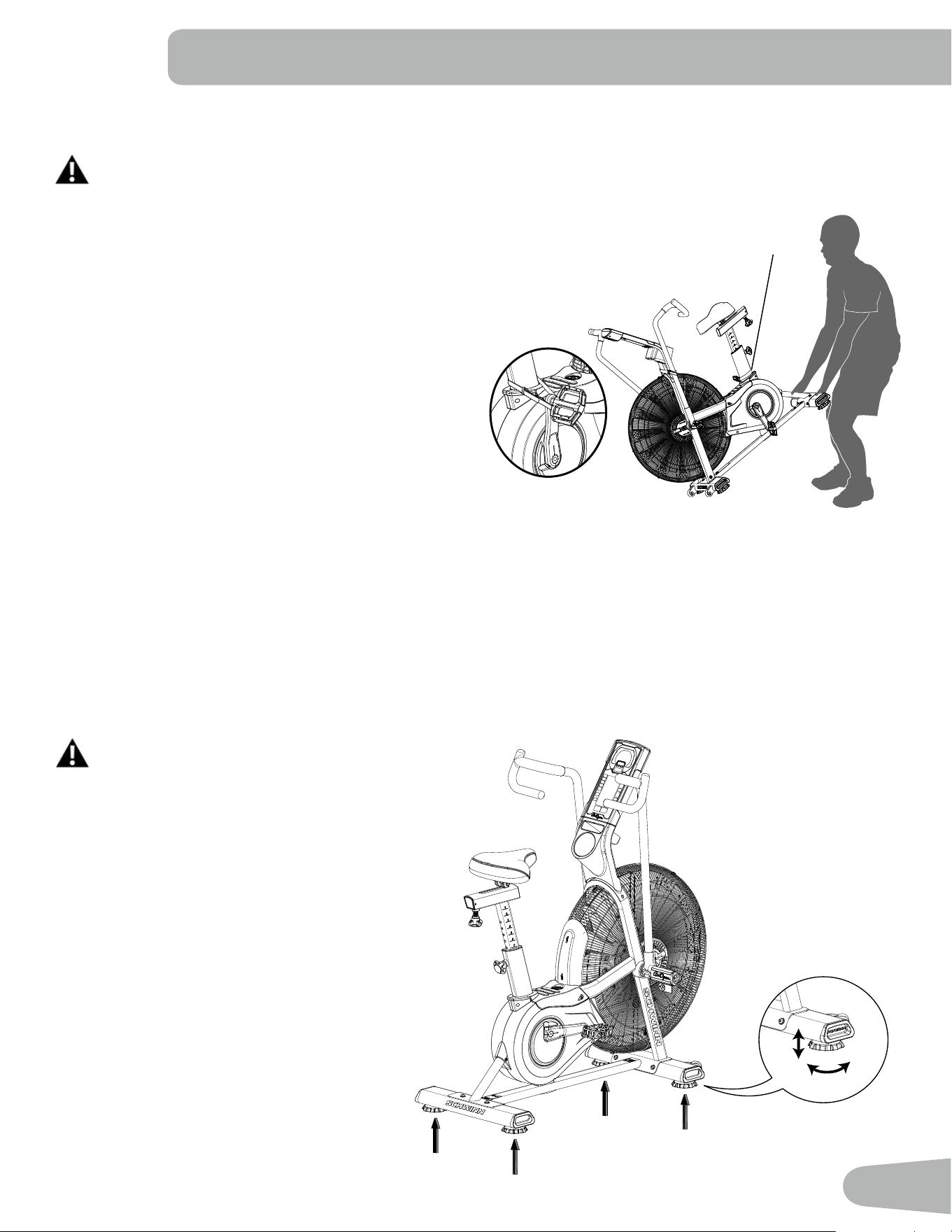
BEFORE YOU START
Moving the Machine
The machine may be moved by one or more persons depending on their physical abilities and capacities.
Make sure that you and others are all physically t and able to move the machine safely. Use proper safety
precautions and lifting techniques.
1. Remove the power adapter.
2. Secure the Crank Arm to the Seat Post with the Transport
andImmobilizationStrap(T).
3. Use the Rear Stabilizer to carefully lift the machine onto
the transport rollers.
Note: Besuretokeepthefanassemblyclearoftheoor.
4. Push the machine into position.
5. Carefully lower the machine into position.
NOTICE: Be careful when you move the machine. Abrupt
motions can affect the computer operation.
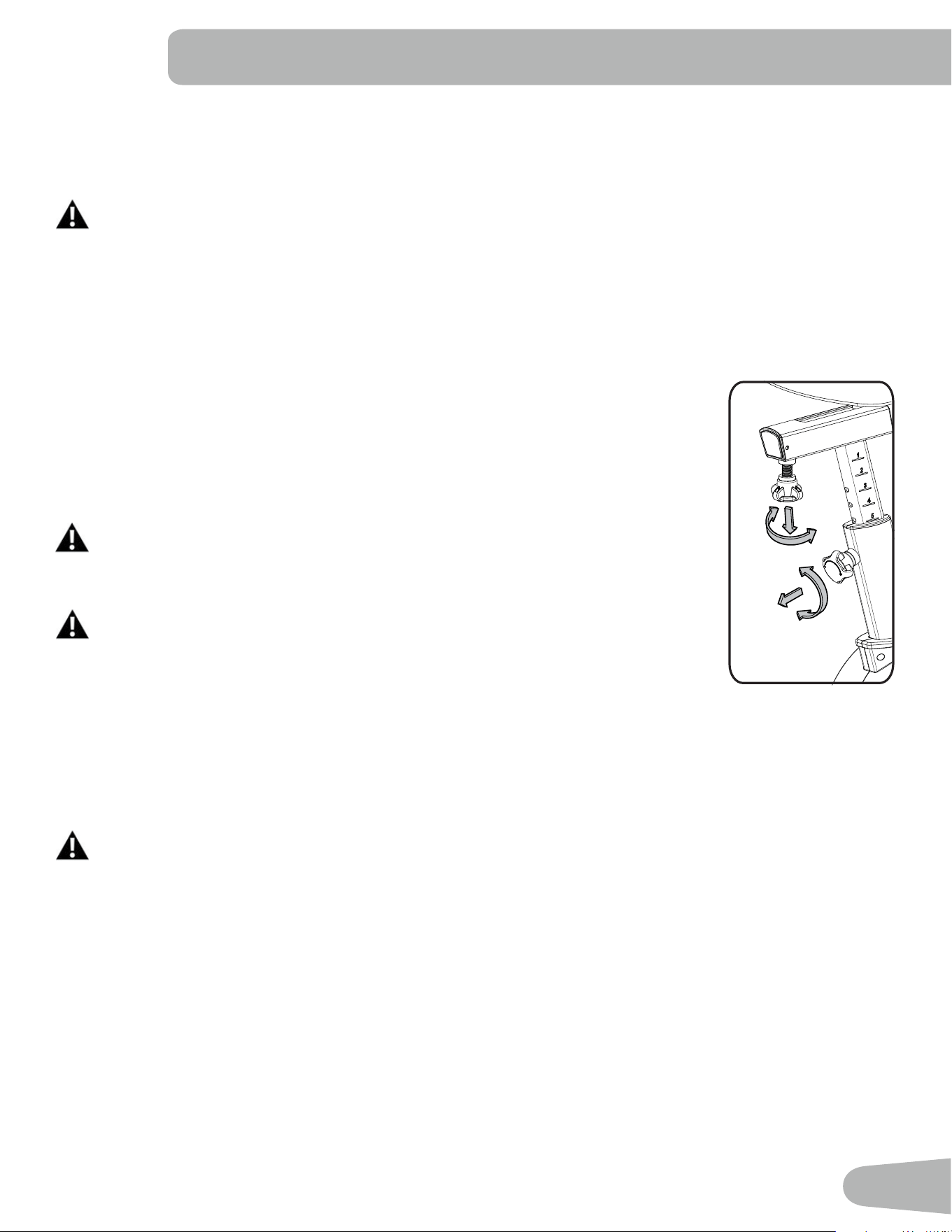
Leveling the Machine
The machine needs to be leveled if your workout area is uneven. Levelers are on each side of the Stabilizers. To adjust:
1. Place the machine in your workout area.
2. Turnthestabilizerfeettoadjustuntiltheyareevenlybalancedandincontactwiththeoor.
Do not adjust the levelers to such a height
that they detach or unscrew from the
machine. Injury to you or damage to the
machine can occur.
Make sure the machine is level and stable before
youexercise.
T
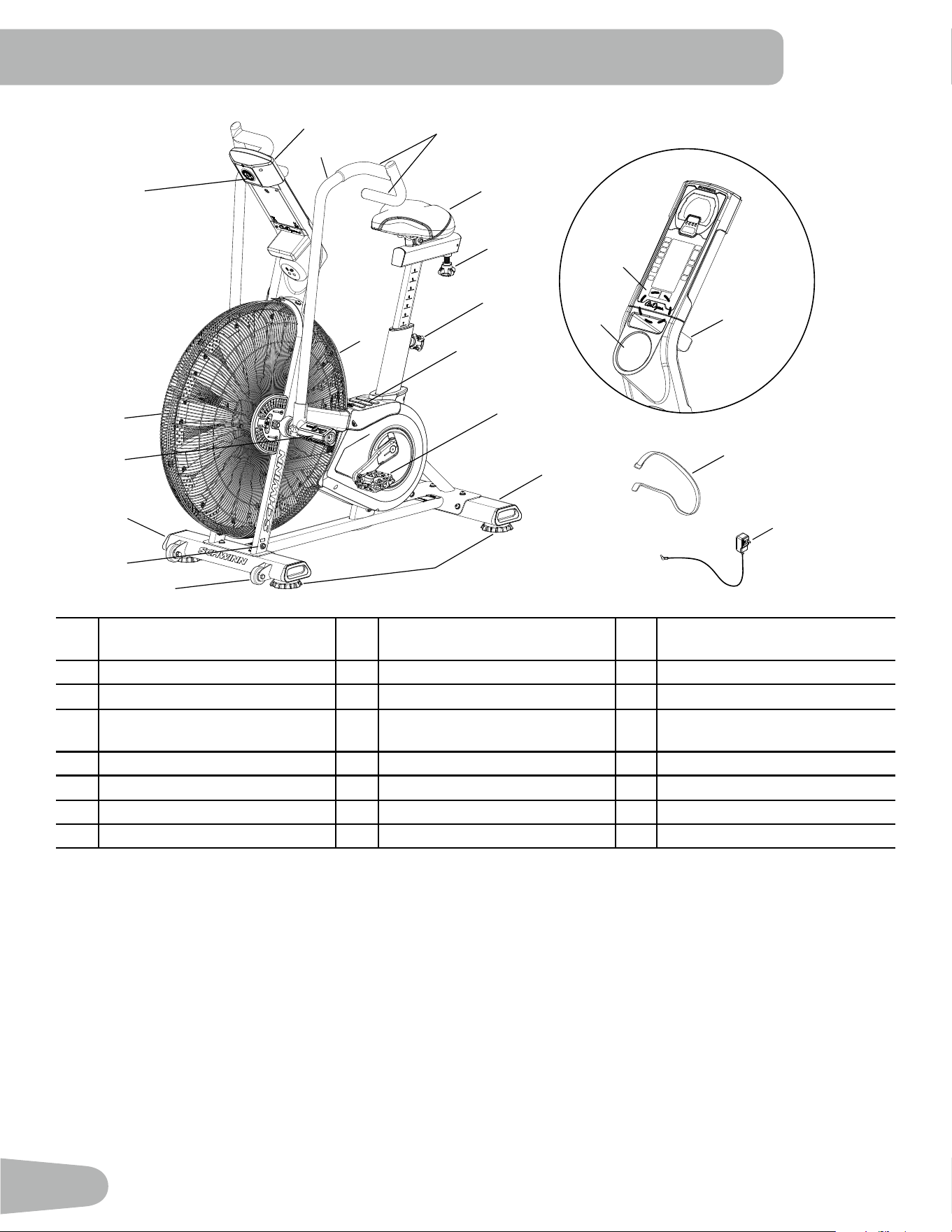
16
A Console I Stabilizer, Rear Q TelemetryHeartRate(HR)
Receiver
B Handlebar J Leveler R Media Rack
C Handle Grip K Transport Roller S Water Bottle Holder
D Seat L Power Connector T Transport and Immobilization
Strap
E Seat Slider Adjustment Knob M Stabilizer, Front U Power adapter
F Seat Post Adjustment Knob N Foot Peg V
AirDyne
®
Air Diverter
G Foot Step Pad O Air Resistance Fan
H Pedal P Battery Compartment
FEATURES
A
B
C
D
Q
E
F
G
H
R
S
I
J
K
L
M
N
P
O
T
U
V
WARNING! Use the values calculated or measured by the machine’s computer for reference purposes only. The
heart rate displayed is an approximation and should be used for reference only. Over exercising may result in
serious injury or death. If you feel faint stop exercising immediately.
17
Console Features
The Console provides information about your workout on the display
screens.
Programs
• Manual
• 20/10 Interval
• 30/90 Interval
• Custom Interval
• Time Target
• Heart Rate Zones
• Calorie Target
• Kilojoules Target
• Miles Target
• Kilometers Target
Tachometer Display
1. LCD tachometer display—themeterisdividedinto60segments
to show CAL/MIN and WATTS metrics for the current workout
performance. For CAL/MIN values the meter utilizes two linear
scales:eachlargetickmarksegment(0-30)indicates1calorie/
minute,andeachsmalltickmarksegment(30-60)indicates1
calorie/minute.
2. Tach metric labels—indicate the type of values currently shown in
the Tach metric display:
• AVG— the Average values display only during workout summary.
• SCAN—in Scan mode the tach automatically moves through the
rate metrics. Each rate display shows for 3 seconds.
•MAX—theMaximumvaluesdisplayonlyduringworkoutsummary.
3. Tach metric display—shows the numeric values for the following rates:
•CAL/MIN—theestimatedcaloriesburnedperminute(basedontheWattsmetric).Themaximumdisplayis999.9.
•WATTS—thepowerthatyouareproducingatthecurrentresistancelevel(1horsepower=746watts).Maximumvalue
is 999.9.
•RPM—themachinerevolutionsperminute(RPM).Themaximumdisplayis9999.
•SPEED—themachinespeedinmilesperhour,toonedecimalplace—forexample,10.5.Themaximumdisplayis
999.9.
4. Tach hill—representstheuser’sRPMperformanceona1-100linearscale(dividedinto10segments).
5. MAX CAL/MIN tick mark—thehighesttickmarkachieved(ontheLCDtachometerdisplay)staysontoshowthemaximum
effort during the current workout.
Tachometer
Display
Program
Data Display
Keypad
2
3
4
5
1
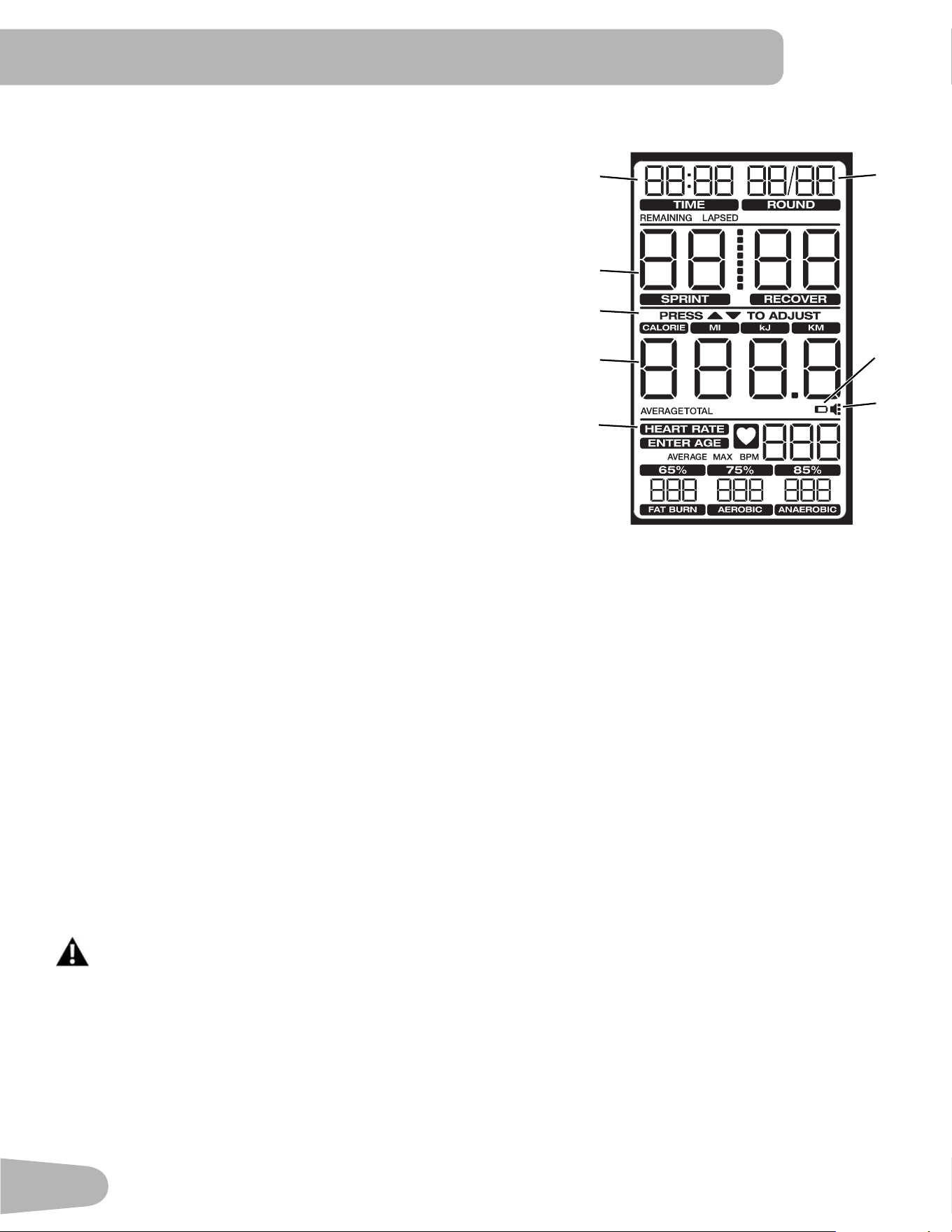
18
Program Data Display
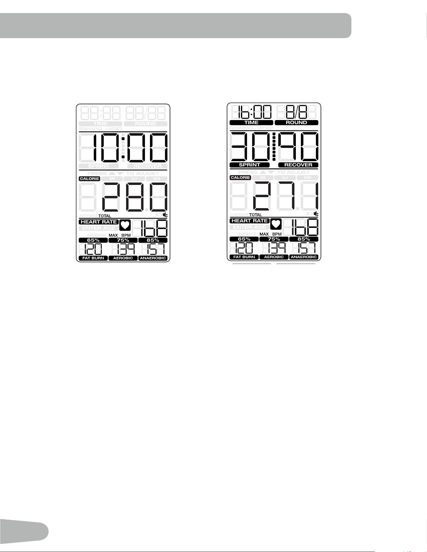
6.TIME
TheTIMEdisplayeldisusedforIntervalworkoutsonly.Duringthe
workout, it shows the remaining time. During workout summary it shows
the total time.
7. ROUND
TheROUNDdisplayeldisusedforIntervalworkoutsonly.Therst00
segment shows the number of the current round. The second 00 seg-
mentshowsthetotalnumberofrounds.Themaximumnumberofrounds
is 49.
8. TIME/INTERVAL area
TheTIME/INTERVALdisplayeldhastwomodes:DefaultandInterval.
The Sprint and Recover labels are enabled for Interval programs only.
Default mode shows lapsed or remaining time, depending on the pro-
graminuse.Timeticksupto99minutesand59seconds(themaximum
time).
Intervalmodeshowstheworkoutstate(Sprint/Recover)andremaining
timeinthatstate.Themaximumis99secondsineachstate.
9. PRESS / TO ADJUST
The prompt “PRESS /TOADJUST”showsonlybeforeaworkoutfor
theoptiontoIncrease/Decreaseatargetornumberofintervals.Thecustomizablemetricashesuntilitisadjusted.
10. Cumulative metrics
Thecumulativemetricsdisplayeldshowsthework(CALORIES,kJ)ordistance(MI,KM)achievedduringtheworkout.
Manual and Interval programs start at 0 and count up. In Target programs the target metric counts down to 0, but the other
metrics count up. Push the CAL MI Kj KM Select button to move to each metric.
The AVERAGE and TOTAL labels identify the values in the workout summary.
11. Battery indicator
The battery indicator turns on when the battery level is 25% or less.
12. Volume
Thevolumeiconfortheaudioalertisalwayson.Thethreedotstotherightindicatethevolumesetting.(Off:iconshows
nodots,Full:iconshowsthreedots.)
13. HEART RATE area
TheHEARTRATEdisplayshowstheheartrateinbeatsperminute(BPM)fromatelemetricheartratesensor.Theicon
willashwhenithasasignalfromatelemetricheartratestrap.Thisdisplayvaluewillbeblankifaheartratesignalisnot
detected. The AVERAGE and MAX labels identify the HR values in the workout summary.
Consult a physician before you start an exercise program. Stop exercising if you feel pain or tightness in
your chest, become short of breath, or feel faint. Contact your doctor before you use the machine again.
Use the values calculated or measured by the machine’s computer for reference purposes only. The heart
rate displayed on the console is an approximation and should be used for reference only.
Theprompt“ENTERAGE”turnsoniftheuserpressestheHRZONESbutton.Thedefaultageis35.
ThevaluesintheFATBURN,AEROBICandANAEROBICheartratezoneeldsarecalculatedfromtheAgevalue.
6
8
9
10
13
7
12
11
19
Keypad Functions
RATE SELECT button- Cycles through the Tach metric display
options(CAL/MIN,WATTS,RPM,SPEED).Pushandholdthe
button for 3 seconds to go to SCAN mode and cycle through
the rates automatically. Each rate is displayed for 3 seconds.
ToexitSCANmode,pushtheRateSelectbutton.
20/10 INTERVAL button- Selects the 20/10 Interval workout.
30/90 INTERVAL button- Selects the 30/90 Interval workout.
CUSTOM INTERVAL button- Selects the Custom Interval
workout.
TIME TARGET button- Selects the Time Target workout.
CAL/kJ TARGET button- Push one time to select the CAL
Target workout. Push two times to select the kJ Target workout.
MI/KM TARGET button- Push one time to select the MI Target
workout. Push two times to select the KM Target workout.
HR ZONES button- Push before or during any workout to start
the Heart Rate Zones calculation.
Increase()button-Increasesavalue(time,targetorage)or
moves through options. Push and hold for quick access.
ENTERbutton-ConrmsasettingforHRZonesandthe
Custom Interval program.
Decrease()button-Decreasesavalue(time,targetorage)
or moves through options. Push and hold for quick access.
CAL MI Kj KM Select button- Cycles through the cumulative metrics.
Volumebutton-Movesthroughthefourvolumelevelsfortheaudioalert:Off,low,med(default),high,med,low,off
START/RESUME button- Starts the timer, and resumes a paused workout
STOP/RESET button- Push one time to stop the workout and display summary. Push two times to reset the console and
erasedata(exceptCustomIntervalprogram).
Remote Heart Rate Monitor
MonitoringyourHeartRateisoneofthebestprocedurestocontroltheintensityofyourexercise.TheConsolecanread
telemetry HR signals from a Heart Rate Chest Strap Transmitter that operates in the 4.5kHz - 5.5kHz range.
Note: The heart rate chest strap must be an uncoded heart rate strap from Polar Electro or an uncoded POLAR
®
com-
patiblemodel.(CodedPOLAR
®
heart rate straps such as POLAR
®
OwnCode
®
chest straps will not work with this
equipment.)
If you have a pacemaker or other implanted electronic device, consult your doctor before using a wireless
chest strap or other telemetric heart rate monitor.
20
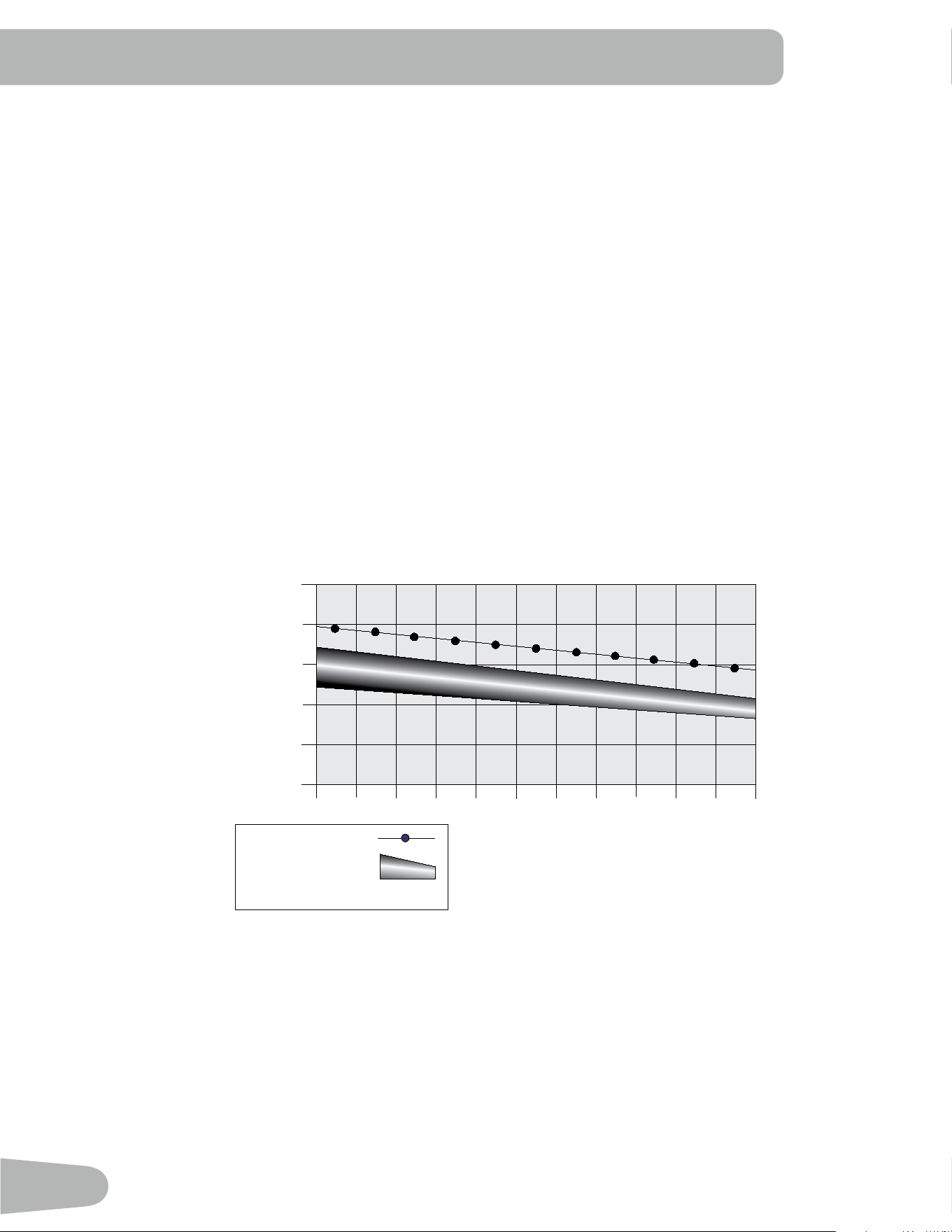
Heart Rate Calculations
Yourmaximumheartrateusuallydecreasesfrom220BeatsPerMinute(BPM)inchildhoodtoapproximately160BPMby
age60.Thisfallinheartrateisusuallylinear,decreasingbyapproximatelyoneBPMforeachyear.Thereisnoindication
thattraininginuencesthedecreaseinmaximumheartrate.Individualsofthesameagecouldhavedifferentmaximum
heartrates.Itismoreaccuratetondthisvaluebycompletingastresstestthanbyusinganagerelatedformula.
Yourat-restheartrateisinuencedbyendurancetraining.Thetypicaladulthasanat-restheartrateofapproximately72
BPM, where as highly trained runners may have readings of 40 BPM or lower.
TheHeartRatetableisanestimateofwhatHeartRateZone(HRZ)iseffectivetoburnfatandimproveyourcardiovas-
cular system. Physical conditions vary, therefore your individual HRZ could be several beats higher or lower than what is
shown.
Themostefcientproceduretoburnfatduringexerciseistostartataslowpaceandgraduallyincreaseyourintensityun-
tilyourheartratereachesbetween60–85%ofyourmaximumheartrate.Continueatthatpace,keepingyourheartrate
in that target zone for over 20 minutes. The longer you maintain your target heart rate, the more fat your body will burn.
The graph is a brief guideline, describing the generally suggested target heart rates based on age. As noted above, your
optimal target rate may be higher or lower. Consult your physician for your individual target heart rate zone.
Note:Aswithallexercisesandtnessregimens,alwaysuseyourbestjudgmentwhenyouincreaseyourexercise
time or intensity.
20-24
FAT-BURNING TARGET HEART RATE
Heart Rate BPM (beats per minute)
Age
25-29
0
50
100
150
200
250
30-34 35-39 40-44 45-49 50-54 55-59 60-64 65-69 70+
196
191
186
181
176
171
166
161
156
151
146
167
162
158
154
150
145
141
137
133
128
126
Maximum Heart Rate
Target Heart Rate Zone
(keep within this range
for optimum fat-burning)
11 8
11 5
11 2
109
106
103
100
97
94
91
88
Auto-Calibration
The console has a built-in sensor which continually corrects for changes in altitude to maintain accurate measurement of
fanresistanceandwattsusedduringexercise.
21
OPERATION
What to Wear
Wearrubber-soledathleticshoes.Youwillneedtheappropriateclothesforexercisethatallowyoutomovefreely.
How Often Should You Exercise
Consult a physician before you start an exercise program. Stop exercising if you feel pain or tightness in
your chest, become short of breath, or feel faint. Contact your doctor before you use the machine again.
Use the values calculated or measured by the machine’s computer for reference purposes only. The heart
rate displayed is an approximation and should be used for reference purposes only.
• 3 times a week for 20 minutes each day.
• Schedule workouts in advance and try to follow the schedule.
Seat Adjustment
Correctseatplacementencouragesexerciseefciencyandcomfort,whilereducingtheriskof
injury.
1. With a Pedal in the forward position, place the heel of your foot to the lowest part of it. Your
leg should be bent slightly at the knee.
2. If your leg is too straight or your foot cannot touch the Pedal, you need to move the seat
downward. If your leg is bent too much, you need to move the seat upward.
Step off the machine before you adjust the seat.
3. Loosen and pull the Seat Post Adjustment Knob on the Seat Post. Adjust the seat to the
desired height.
Do not lift the Seat post above the “STOP” mark on the Seat Post.
4. Release the Seat Post Adjustment Knob to engage the locking pin. Be sure that the pin is
fully engaged and fully tighten the adjustment knob.
5. To move the seat closer to, or away from the console, loosen the seat adjustment knob.
Slide the seat to the desired position and fully tighten the knob.
Using the Machine
Be aware that the Pedals, Handlebars and Resistance Fan are connected and when any of these parts move
the others do as well.
Carefully mount the machine using the Foot Step Pad if necessary. Adjust the Seat and Pedals before starting a workout.
LowerBodyWorkout:SlowlypedalwithyourarmsrelaxedatyoursidesorwithyourhandsrestingontheHandGripsas
the Handlebars move.
Full Body Workout: Grasp the Hand Grips with your palms down. Push and pull the Handlebars as you pedal, keeping
yourelbowslowandnexttoyourbody.
UpperBodyWorkout:GrasptheHandGripsrmlywithpalmsdownandplaceyourfeetontheFootPegs.Leanslightly
forward at the hips with your back straight and shoulders down. Now push and pull the Handlebars
Note: You may need to safely push a Pedal to assist with starting the workout.
To increase the air resistance and workload, increase your level of activity. Toexerciseallthemusclegroupsinyourarms,
alter your grasp to palms up for part of the workout.
22
When done with your workout, reduce the Resistance Fan speed until the machine fully stops.
This bike cannot stop the Pedals independently of the Resistance Fan. Reduce the pace to slow the
Resistance Fan and Pedals to a stop. Do not dismount the bike until the Pedals have come to a complete
stop. Be aware that the moving Pedals can strike the backs of the legs.
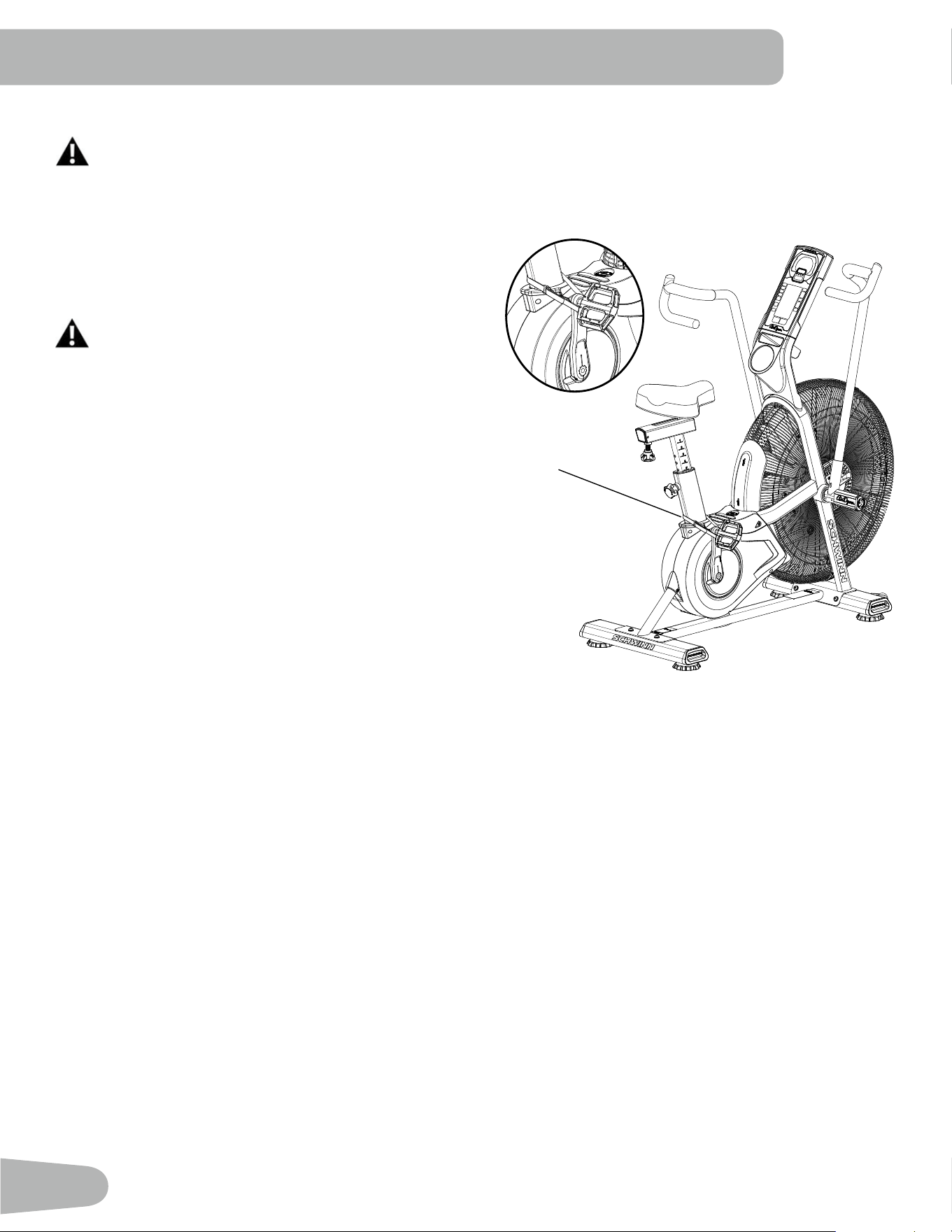
Locking the Fan Assembly / Storage
When the machine is not in use, be sure to lock the Fan As-
sembly with the Transport and Immobilization Strap. The fan
assembly should be locked for storage of the machine.
For safe storage of the machine, remove the batter-
ies and install the Transport and Immobilization
Strap to secure the Resistance Fan. Place the ma-
chine in a secure location away from children and
pets. Be aware that the Pedals, Handlebars and
Resistance Fan are connected and when any of
these parts move, the others do as well.
To lock the Fan Assembly:
1. Move the Pedals so that one Crank Arm is as close as
possible to the Seat Post.
2. WraptheTransportandImmobilizationStrap(T)around
the Crank Arm and the Seat Post and put the end of the
strap through the metal ring. Tighten the strap to prevent
movement of the Pedals and secure the strap.
Power-Up / Idle Mode
The Console will enter Power-Up / Idle Mode if any button is pushed, or if it receives a signal from the RPM sensor as a
result of pedaling the machine.
Note: The Console will display the battery indicator if the battery level is 25% or less.
Auto Shut-Off (Sleep Mode)
IftheConsoledoesnotreceiveanyinputinapproximately2minutes,itwillautomaticallyshutoff.TheLCDdisplayisoff
while in Sleep Mode.
Note: The Console does not have an On/Off switch.
Manual Workout
The Manual program lets you start a workout without entering any information.
1. Sit on the machine.
2. With the Console in Idle Mode, push the START/RESUME button to start the workout program, and start to pedal.
3. To pause the workout and see your metrics, push the STOP/RESET button one time. Push START/RESUME to
continue.
4. When done with your workout, push the STOP/RESET button two times to end the workout.
T

23
20/10 Interval Workout
TheConsoleallowsyoutoselectanIntervalworkoutof20secondsSprintfollowedby10secondsRecover(1round).The
defaultnumberofroundsis8rounds(totaltime-4minutes).
1. Sit on the machine.
2. With the Console in Idle Mode, push the 20/10 INTERVAL button.
3. TheROUNDeldblinks(defaultvalueis8).Tochangethenumberofrounds,usetheIncrease/Decreasebuttons.
4. Push the START/RESUME button to start the timer, and start to pedal.
5. The program starts in the Sprint phase and counts down each phase and the total workout time. The work and
distance values count up. An audible alert sounds 3 seconds before each phase change.
30/90 Interval Workout
TheConsoleallowsyoutoselectanIntervalworkoutof30secondsSprintfollowedby90secondsRecover(1round).The
defaultnumberofroundsis8rounds(totaltime-16minutes).
1. Sit on the machine.
2. With the Console in Idle Mode, push the 30/90 INTERVAL button.
3. TheROUNDeldblinks(defaultvalueis8).Tochangethenumberofrounds,usetheIncrease/Decreasebuttons.
4. Push the START/RESUME button to start the timer, and start to pedal.
5. The program starts in the Sprint phase and counts down each phase and the total workout time. The work and
distance values count up. An audible alert sounds 3 seconds before each phase change.
Custom Interval Workout
The Console allows you to select a Custom Interval workout and enter your own values for Sprint, Recover and number of
rounds.
1. Sit on the machine and start to pedal.
2. With the Console in Idle Mode, push the CUSTOM INTERVAL button.
3. TheConsolewillshowthedefaultvaluesorthelastcustomvalues.TheROUNDeldblinks.
Note: ThedefaultRoundvalueis5(maximumis99).ThedefaultSprintvalueis60seconds(maximumis99).The
defaultRecovervalueis60seconds(maximumis99).
4. TheROUNDeldblinks.Tochangethevalue,usetheIncrease/DecreasebuttonsandpushENTERtoconrmand
gotothenexteld.
5. TheSPRINTeldblinks.Tochangethevalue,usetheIncrease/Decreasebuttonstoadjustthetimein5second
increments.PushENTERtoconrmandgotothenexteld.
6. TheRECOVEReldblinks.Tochangethevalue,usetheIncrease/Decreasebuttonstoadjustthetimein5second
increments.PushENTERtoconrm.
7. Push START/RESUME to start the timer, and start to pedal.
8. The program starts in the Sprint phase and counts down each phase and the total workout time. The work and
distance values count up. An audible alert sounds 3 seconds before each phase change.
Time Target Workout
The Console allows you to select a Time Target workout and enter your own Time value. The default value is 10 minutes.
1. Sit on the machine.
2. With the Console in Idle Mode, push the TIME TARGET button.
3. TheTIME/INTERVALeldblinks(defaultvalueis10:00).Tochangethevalue,usetheIncrease/Decreasebuttonsto
adjust in 1 minute increments.

24
4. Push the START/RESUME button to start the timer, and start to pedal.
5. The program starts and counts down the time. The CALORIE, kJ, MI and KM values count up.
Calories Target Workout
The Console allows you to select a Calories Target workout and enter your own Calories value. The default value is 100
calories.
1. Sit on the machine.
2. With the Console in Idle Mode, push the CAL/kJ TARGET button one time.
3. TheCALORIEmetricseldblinks(defaultvalueis100).Tochangethevalue,usetheIncrease/Decreasebuttonsto
adjust in 25 calorie increments.
4. Push the START/RESUME button to start the timer, and start to pedal.
5. The program starts and counts down the calories. The total time, kJ, MI and KM values count up.
Kilojoules (kJ) Target Workout
The Console allows you to select a Kilojoules Target workout and enter your own Kilojoules value. The default value is
400 kilojoules.
1. Sit on the machine.
2. With the Console in Idle Mode, push the CAL/kJ TARGET button two times.
3. ThekJmetricseldblinks(defaultvalueis400).Tochangethevalue,usetheIncrease/Decreasebuttonstoadjustin
100 kilojoule increments.
4. Push the START/RESUME button to start the timer, and start to pedal.
5. The program starts and counts down the kilojoules. The total time, CALORIE, MI and KM values count up.
Miles Target Workout
The Console allows you to select a Miles Target workout and enter your own Miles value. The default value is 1 mile.
1. Sit on the machine.
2. With the Console in Idle Mode, push the MI/KM TARGET button one time.
3. TheMImetricseldblinks(defaultvalueis1.0).Tochangethevalue,usetheIncrease/Decreasebuttonstoadjustin
0.5 mile increments.
4. Push the START/RESUME button to start the timer, and start to pedal.
5. The program starts and counts down the miles. The total time, CALORIE, kJ and KM values count up.
Kilometers Target Workout
The Console allows you to select a Kilometers Target workout and enter your own Kilometers value. The default value is 1
kilometer.
1. Sit on the machine.
2. With the Console in Idle Mode, push the MI/KM TARGET button two times.
3. TheKMmetricseldblinks(defaultvalueis1.0).Tochangethevalue,usetheIncrease/Decreasebuttonstoadjustin
1 kilometer increments.
4. Push the START/RESUME button to start the timer, and start to pedal.
5. The program starts and counts down the kilometers. The total time, CALORIE, kJ and MI values count up.

25
Heart Rate Zones
The Console allows you to set your Heart Rate Zones and use the calculated values to monitor your workout intensity.
This feature can be used in conjunction with all of the other programs.
1. Sit on the machine.
2. WiththeConsoleinIdleMode,pushtheHRZONESbutton.Theprompt“ENTERAGE”turnson.Thedefaultageis
35. To adjust the Age value, use the Increase/Decrease buttons and push ENTER.
TheConsolecalculatesvaluesfortheFATBURN,AEROBICandANAEROBICheartratezoneeldsfromtheAge
value.
Consult a physician before you start an exercise program. Stop exercising if you feel pain or tightness in
your chest, become short of breath, or feel faint. Contact your doctor before you use the machine again.
Use the values calculated or measured by the machine’s computer for reference purposes only. The heart
rate displayed on the console is an approximation and should be used for reference only.
3. TheHEARTRATEdisplayshowstheheartrateinbeatsperminute(BPM)fromaheartratecheststraptransmitter.
TheiconwillashwhenithasasignalfromaHRcheststrap.
Note: If no heart rate is detected, the display will be blank.
When the Console goes into Sleep Mode or the power is removed, the Age value is reset to default and the HR Zones
turn off.
Pausing / Results Mode
To pause a workout and see the workout summary:
1. Push the STOP/RESET button one time.
Not e: The Console will automatically pause if there is no RPM signal for 5 minutes.
2. To continue your workout, push START/RESUME.
To end the workout, push the STOP/RESET button two times. The Console will go into Idle Mode.
When you complete or stop a workout, the Console will display a summary of your workout values. To stop a workout and
see the summary, push STOP/RESET and the Console will go into Results mode.
The Tachometer Display shows the user’s average CAL/MIN and WATTS, and the MAX CAL/MIN tick mark for that
workout.TheTachhillshowstheaverageRPM.TheTachmetricdisplayshowstheaverageandmaximumvaluesforthe
selectedmetric.IftheconsolewasinSCANmode,thedisplaycyclesthroughtheaverageandmaximumvaluesforCAL/
MIN, WATTS, RPM and SPEED.
26
TheProgramDataDisplayshowsthetotaltime,CALORIE,MI(miles),kJ(kilojoules),andKM(kilometers)metrics.Push
the CAL MI Kj KM Select button to cycle through the metrics. The summary for Interval programs shows total time, rounds
and interval time.
SPEED
RPM
CAL/MIN
WAT T S
RATE
SELECT
20/10
INTERVAL
30/90
INTERVAL
CUSTOM
INTERVAL
TIME
TARGET
ZONES
HR
START
RESUME
STOP
RESET
CAL
MI
kJ
KM
SELECT
TARGET
MI/KM
CAL/kJ
TARGET
ENTER
Manual and Target Programs
SPEED
RPM
CAL/MIN
WAT T S
RATE
SELECT
20/10
INTERVAL
30/90
INTERVAL
CUSTOM
INTERVAL
TIME
TARGET
ZONES
HR
START
RESUME
STOP
RESET
CAL
MI
kJ
KM
SELECT
TARGET
MI/KM
CAL/kJ
TARGET
ENTER
Interval Programs
The Heart Rate area cycles the Average HR and MAX HR values. If HR Zones were calculated for the program, the
values are displayed.
The Results display will show for 5 minutes and then reset.
Push STOP/RESET to stop the Results display and go back to Idle Mode.
CONSOLE SERVICE MODE
Console Service Mode
The Console Service Mode lets you see the total time and distance the machine has been used, adjust the altitude value
foramoreaccuratecaloriecount,orndoutwhichversionofFirmwareisinstalled.
1. HolddowntheSTOP/RESETbuttonandDecrease()buttontogetherfor3secondswhileintheIdleModetogointo
the Console Service Mode.
2. The Console display shows the machine statistics:
•TotalMachineTime—numberofhours(inTime/Intervaleld).Maximumdisplayis9999.
•TotalMachineDistance—numberofmiles(incumulativemetricseld).
Push the Decrease button to go to the metric display option:
•TotalMachineTime—numberofhours(inTime/Intervaleld).Maximumdisplayis9999.
•TotalMachineDistance—numberofkilometersin10-kilometerincrements(incumulativemetricseld).
3. PushSTOP/RESETtoexitConsoleServiceMode.PushtheDecreasebuttontogotothenextoption.
4. The Console display shows the Firmware Version.
5. PushSTOP/RESETtoexitConsoleServiceMode.
InServiceModeiftheConsoledoesnotreceiveanyinputinapproximately2minutes,itgoesintoSleepMode.
27
Read all maintenance instructions fully before you start any repair work. In some conditions, an assistant is required to do
the necessary tasks.
Equipment must be regularly examined for damage and repairs. The owner is responsible to make sure that
regular maintenance is done. Worn or damaged components must be repaired or replaced immediately.
Only manufacturer supplied components can be used to maintain and repair the equipment.
If at any time the Warning labels become loose, unreadable or dislodged, contact your local distributor for
replacement labels.
Disconnect all power to the machine before you service it.
Daily: Beforeeachuse,examinetheexercisemachineforloose,broken,damaged,orwornparts.
Donotuseiffoundinthiscondition.Repairorreplaceallpartsattherstsignofwearor
damage. After each workout, use a damp cloth to wipe your machine and Console free of
moisture.
Note:AvoidexcessivemoistureontheConsole.
NOTICE: If necessary, only use a mild dish soap with a soft cloth to clean the Console. Do
not clean with a petroleum based solvent, automotive cleaner, or any product
that contains ammonia. Do not clean the Console in direct sunlight or at high
temperatures. Be sure to keep the Console free of moisture.
Weekly: Clean the machine to remove any dust, dirt, or grime from the surfaces.
Check for smooth seat operation. If needed, sparingly apply a thin coating of silicone lube
to ease operation.
Silicone lubricant is not intended for human consumption. Keep out of reach of
children. Store in a safe place.
Note: Do not use petroleum based products.
Monthly
or after 20
hours:
Check pedals, crank arms and handlebars. Make sure all bolts and screws are tight.
Tighten as necessary.
Check drive belt for signs of wear. Rotate crank arms by hand and observe the belt through
the fan cage.
Be aware that the Crank Arms, Handlebars and Resistance Fan are connected
and when any of these parts move, the others do as well.
When the machine is used in a Commercial environment, the Pedals must be replaced every year to
maintain maximum user safety and performance. Only use replacement Pedals available from
Nautilus. Other brands of Pedals may not be designed for Indoor Cycling or this product, and can
cause danger to users and bystanders, and will void the warranty.
MAINTENANCE
28
Replacing the Console Batteries
The Console will display the Battery Indicator icon when the batteries are around 25% of their rated power during power
up. If you use rechargeable batteries, the optional power adapter will not recharge the batteries.
To open the battery bay, loosen the preinstalled screw in the cover. When replacing the batteries, make sure the batteries
point in the +/- direction shown in the battery bay.
Note:TheconsoleusesDsizebatteries(LR20)
!
Do not mix old and new batteries.
Do not mix alkaline, standard (carbon-zinc), or rechargeable (Ni-Cd, Ni-MH, etc) batteries.
X2
+
–
29
Maintenance
Parts
A Console Q Leveler GG Power Inlet Assembly
B Console Mast R Seat Adjustment Knob HH Fan Cage, Upper Left
C Water Bottle Holder S Shroud, Left II Fan Cage, Lower Left
D Frame T Crank Arm, Left JJ Fan Cage, Lower Filler
E Stabilizer, Front U Pedal, Left KK Linkage Arm
F Transport Wheel V Shroud, Top LL Arm Pivot, Right
G Fan Cage, Upper Right W Foot Step Pad MM Arm Pivot, Left
H Fan Cage, Front X Grommet NN Resistance Fan Assembly
I Fan Adjustment Plate Cover Y Seat Post OO RPM(Speed)SensorAssembly
J Fan Cage, Lower Right Z Seat PP Speed Sensor Magnets
K Handlebar, Right AA Handlebar, Left QQ Drive Pulley
L Foot Peg, Right BB Foot Peg, Left RR Drive Belt
M Pedal, Right CC Strap, Transport/Immobilization SS Crank Link Assembly
N Crank Arm, Right DD Data Cable, Upper TT Power Adapter
O Shroud, Right EE Power Wire, Upper UU
AirDyne
®
Air Diverter
P Stabilizer, Rear FF Data Cable, Lower
B
A
C
D
E
F
G
H
H
I
I
J
K
L
M
N
O
P
Q
Q
R
S
T
U
V
X
Y
Z
AA
BB
CC
DD
EE
FF
GG
HH
II
JJ
KK
LL
W
TT
FF
GG
NN
OO
PP
(X3)
QQ
RR
MM
SS
GG
NN
UU

30
TROUBLESHOOTING
Condition/Problem Things to Check Solution
Console will not power up/
turn on/start
If bike has AC adapter,
checkelectrical(wall)
outlet
Make sure unit is plugged into a functioning wall outlet.
If bike has AC adapter,
check connection at unit
Connection should be secure and undamaged. Replace
adapter or connection at unit if either are damaged.
If bike has batteries,
check Battery Indicator
on console or check
batteries.
Make sure batteries are installed correctly. If batteries are
correctly installed, replace with a set of new batteries.
Check data cable integrity All wires in cable should be intact. If any are visibly crimped or
cut, replace cable.
Check data cable
connections/orientation
Make sure cable is connected securely and oriented properly.
Small latch on connector should line up and snap into place.
Check console display for
damage
Check for visual sign that console display is cracked or
otherwise damaged. Replace Console if damaged.
If the above steps do not resolve the problem, contact your
local distributor for further assistance.
Speed displayed is not
accurate
Check Speed Sensor
Magnetposition(requires
fancoverremoval)
Speed Sensor Magnets should be in place on Fan assembly.
Speed displayed is always
“0”/stuckinPausemode
Data cable Make sure the data cable is connected to the back of the
Console and the main frame assembly.
SpeedSensor(requires
fancoverremoval)
Make sure the Speed Sensor Magnets and the Speed Sensor
are in place.
No speed/RPM reading Check data cable integrity All wires in cable should be intact. If any are cut or crimped,
replace cable.
Check data cable
connections/orientation
Be sure cable is connected securely and oriented properly.
Small latch on connector should line up and snap into place.
Check Speed Sensor
Magnetposition(requires
fancoverremoval)
Magnets should be in place on Fan assembly.
Check Speed Sensor
Assembly(requiresfan
coverremoval)
Speed Sensor Assembly should be aligned with magnets and
connected to data cable. Realign sensor if necessary. Replace
if there is any damage to the sensor or the connecting wire.
Console displays battery
icon
Batteries Replace batteries
Unit operates but
Telemetric Heart Rate not
displayed
ChestStrap(optional) Strap should be “POLAR
®
”compatibleanduncoded.Make
sure strap is directly against skin and contact area is wet.
Chest Strap Batteries If strap has replaceable batteries, install new batteries.
Interference Trymovingunitawayfromsourcesofinterference(TV,Micro-
wave,etc).
Replace Chest Strap If interference is eliminated and HR does not function, replace
strap.
Replace Console If HR still does not function, replace Console.

31
Condition/Problem Things to Check Solution
Consoleshutsoff(enters
sleepmode)whileinuse
Check data cable integrity All wires in the cable should be intact. If any are cut or crimped,
replace cable.
Check data cable
connections/orientation
Be sure cable is connected securely and oriented properly.
Small latch on connector should line up and snap into place.
If bike has batteries,
check Battery Indicator
on console or check
batteries.
Make sure batteries are installed correctly. If batteries are
correctly installed, replace with a set of new batteries.
Check Speed Sensor
Magnetposition(requires
fancoverremoval)
Speed Sensor Magnets should be in place on Fan assembly.
Check Speed Sensor
Assembly
Speed Sensor Assembly should be aligned with magnets and
connected to data cable. Realign sensor if necessary. Replace
if there is any damage to the sensor or the connecting wire.
Consoledisplays“err1”
message
Check Console keypad for
stuck key
Contact your local distributor for further assistance.
Unit rocks/does not sit
level
Check leveler adjustment Leveling feet may be turned in or out to level bike.
Check surface under unit Adjustmentmaynotbeabletocompensateforextremelyun-
even surfaces. Move bike to level area.
Pedalsloose/unitdifcult
to pedal
Check pedal to crank
connection
Pedal should be tightened securely to crank arm. Be sure con-
nection is not cross-threaded.
Checkcrankarmtoaxle
connection
Crankarmshouldbetightenedsecurelytoaxle.(Screwtorque:
M8=40N
.
m;M10=60N
.
m.)
Crank link to pulley
connection
If the left crank arm still feels loose with correct torque applied
and the crank link shaft is moving with the crank arm, replace
the crank link assembly.
Clicking sound when
pedaling
Check pedal to crank
connection
Remove pedals. Make sure there is no debris on threads, and
reinstall the pedals.
Check fan alignment
(requiresfancover
removal)
Refertothe“AdjusttheBeltTension”procedureintheService
Manual.
Seat post movement Check locking pin Be sure adjustment pin is locked into one of the seat post
adjustment holes.
Check locking knob Be sure knob is securely tightened.
Handlebar arms click/tick
during movement
Check hardware Screws at the base of handlebar arms should be tightened
securely.(Screwtorque=40N
.
m.)

Nautilus® Bowex® Schwinn® Universal®
8007518.121517.J
EN