1
Questions? Call 800.GE.CARES (800.432.2737)
or Visit our Website at: GEAppliances.com
Installation Range Hood
Instructions Power Cord Kit
Read these instructions completely and carefully.
•
IMPORTANT – Save these
instructions for local inspector’s use.
•
IMPORTANT – Observe all
governing codes and ordinances.
• Note to Installer – Be sure to leave these
instructions with the Consumer.
• Note to Consumer – Keep these
instructions for future reference.
BEFORE YOU BEGIN
CAUTION –
• To reduce the risk of fire and electric shock, this range
hood cord connection kit should be used only with
GE series range hood models beginning with JN3, JV3
(EXCEPT MODELS JV39), JV4, JV5 and JV6 (EXCEPT
MODELS JV69).
• Skill level – Installation of this power cord kit requires
basic mechanical skills.
• Completion time – 1-3 hours
• Proper installation is the responsibility of the installer.
• Product failure due to improper installation is not
covered under the GE Appliance Warranty.
JXHC1
PART QUANTITY
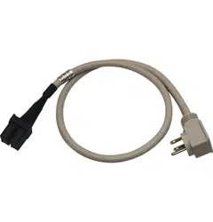
Power Cord with Molded 1
Strain Relief
Wire Nuts 2
Installation Instructions 1
PARTS INCLUDED
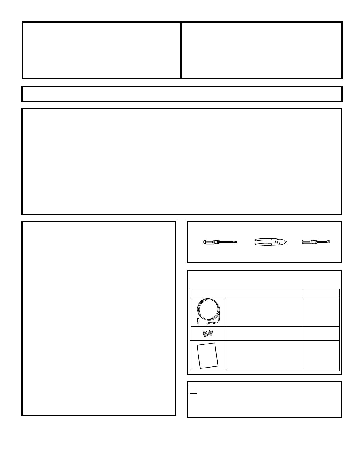
Flat blade and
Phillips head screwdrivers
1/4″ NutdriverWire cutters/
strippers
WARNING – Before beginning the
installation, switch power off at service panel and lock the
service disconnecting means to prevent power from being
switched on accidentally. When the service disconnecting
means cannot be locked, securely fasten a prominent
warning device, such as a tag, to the service panel.
WARNING – Improper grounding can
result in a risk of electric shock.
Consult a qualified electrician if the grounding
instructions are not completely understood, or if doubt
exists as to whether the appliance is properly grounded.
Do not use an extension cord. If the power supply cord
is too short, have a qualified electrician install an outlet
near the appliance.
FOR YOUR SAFETY:
REMOVE CONNECTION
BOX COVER
Locate the hood junction box and remove its cover.
1
This appliance must be grounded. In the event of an
electrical short circuit, grounding reduces the risk of
electric shock by providing an escape wire for the
electric current. This appliance is equipped with a
cord having a grounding wire with a grounding plug.
The plug must be plugged into an outlet that is
properly installed and grounded.
TOOLS YOU WILL NEED
GROUNDING INSTRUCTIONS
2
Installation Instructions
164D4290P045
49-80087-3
09-03 JR
Printed in the United States
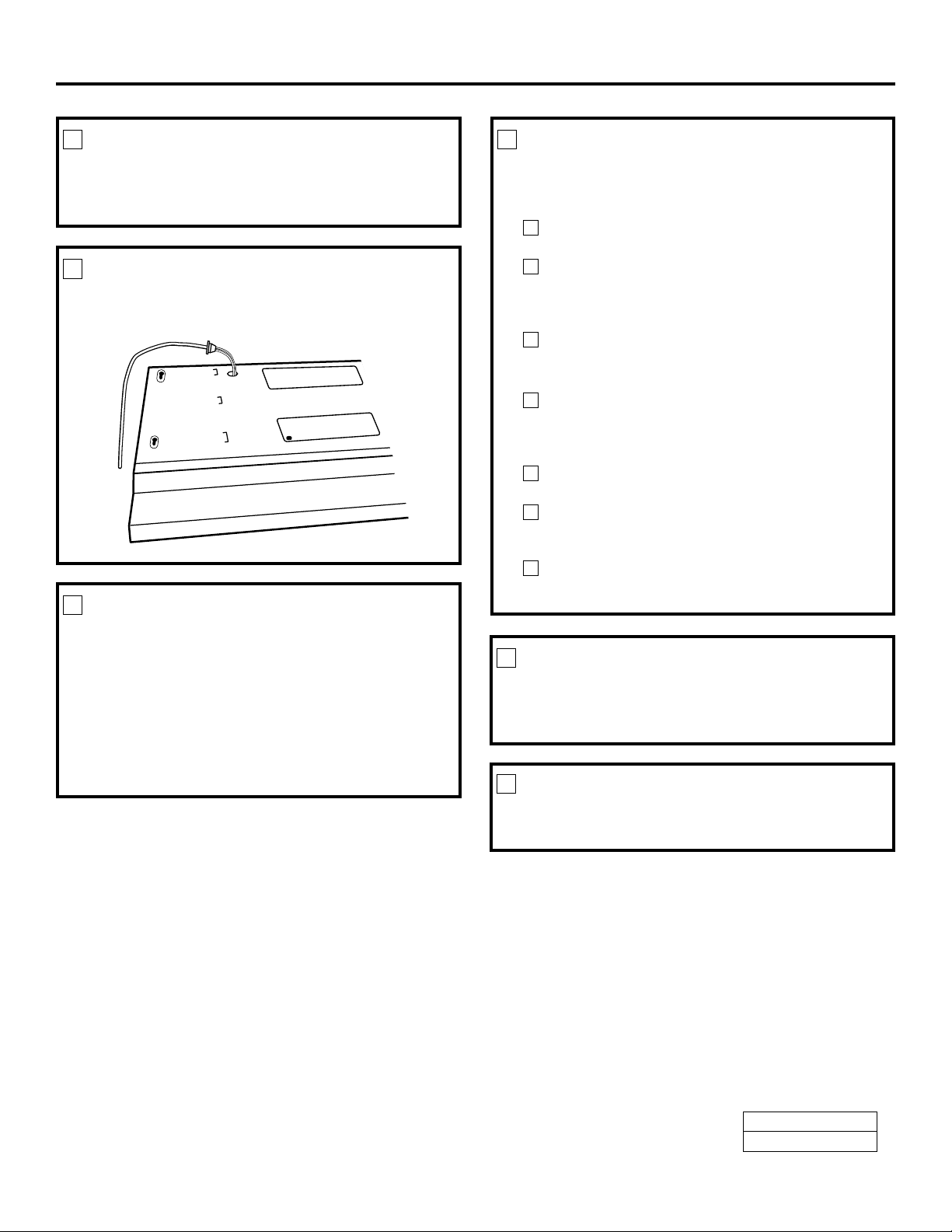
REMOVE KNOCKOUT
Insert the blade of a flat blade screwdriver into the
preferred knockout slot and bend until the knockout
is removed.
2
THREAD WIRES THROUGH
THE KNOCKOUT
Thread the cord wires through the knockout hole.
3
PULL CORD THROUGH
THE KNOCKOUT
NOTE: The cord MUST be PULLED through the
knockout hole, rather than pushed. Pushing the cord
through will not allow the strain relief to fit properly
into the knockout.
Pull the cord at various angles until the strain relief lip
is firmly seated in the knockout. The strain relief is
designed to fit tightly into the knockout, so a firm pull
will be necessary.
4
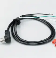
CONNECT THE CORD WIRES
Inspect the junction box wires to determine the type
of connections that should be made.
For hoods with a ground screw:
Connect the green ground wire to the green
ground screw.
Using the wire nuts provided, connect the black
power cord lead to the stripped black lead and the
white power cord lead to the stripped white lead
in the connection box.
All electrical connections should be inspected
carefully before replacing the connection box cover.
For hoods with a ground wire:
Using the (2) wire nuts provided, connect the
black power cord lead to the black junction box
lead. Connect the white power cord lead to the
white junction box lead.
Locate the power cord green ground wire, and cut
off the ring terminal and strip 1/2″ of insulation.
Obtain a third wire nut (not provided) and connect
the power cord ground wire to the green junction
box lead.
All electrical connections should be inspected
carefully before replacing the junction box cover.
D
C
B
A
C
B
A
5
REPLACE CONNECTION
BOX COVER
Replace the connection box cover using the screws
removed in Step 1.
6
INSTALL HOOD
Return to and proceed with the Installation
Instructions to install the range hood.
7