
Water Softening
system
Safety Information . . . . . . . . . . . . . . . . .2
Installation Instructions . . . . . . . .3–15
Step-by-step instructions . . . . . . . . . . . .6–15
Operating Instructions
Breaking a salt bridge . . . . . . . . . . . . . . . . .17
Cleaning the injector and screen . . . . . . . .17
Service . . . . . . . . . . . . . . . . . . . . . . . . . . . . . . .16
Water softener system . . . . . . . . . . . . .16–17
Care and Cleaning . . . . . . . . . . . . . . . . .18
Troubleshooting Tips . . . . . . . . . . .19–21
Advanced Programming . . . . . . .22–23
Advanced Troubleshooting . . . .24–27
Consumer Support
Checking the Brine Draw
and Refill Function . . . . . . . . . . . . . . . . . . . . .30
Consumer Support . . . . . . . . . . . .Back Cover
Control Valve Diagram/Parts . . . . . . . .31, 33
Flow Diagrams . . . . . . . . . . . . . . . . . . . .28–29
Systems Diagram/Parts . . . . . . . . . . . .32, 33
Warranty (U.S.) . . . . . . . . . . . . . . . . . . . . . . . .34
Warranty (Canada) . . . . . . . . . . . . . . . . . . . .35
Water Meter . . . . . . . . . . . . . . . . . . . . . . . . . .30
ge.com
215C1173P030 49-50218-1 04-07 JR
Write the model and serial
numbers here:
Model # ________________
Serial # ________________
To find these numbers, lift the
cover and look on the rim
below the control panel.
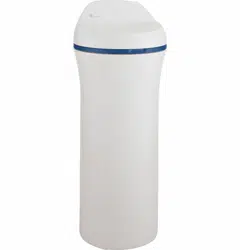
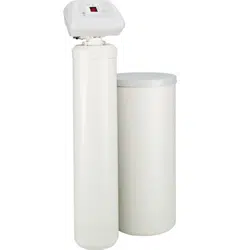
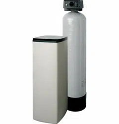
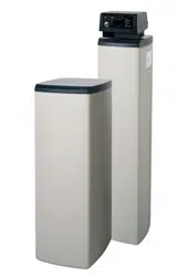
Models GNPR40L, GNPR48L
Owner’s Manual &
Installation Instructions
Water Softening
System
IMPORTANT SAFETY INFORMATION.
READ ALL INSTRUCTIONS BEFORE USING.
SAFETY PRECAUTIONS
■ Check and comply with your state and local codes.
You must follow these guidelines.
■ Use care when handling the water softening
system. Do not turn upside down, drop, drag
or set on sharp protrusions.
■ Water softening systems using sodium chloride
(salt) for regeneration add sodium to the water.
Persons on sodium restricted diets should consider
the added sodium as part of their overall intake.
Potassium chloride can be used as an alternative
to sodium chloride in your softener.
■
The water softening system works on 12 volt-60 Hz
electrical power only. Be sure to use only the
included transformer.
■ Transformer must be plugged into an indoor
120 volt, grounded outlet only.
■ Use clean water softening salts only, at least 99.5%
pure. NUGGET, PELLET or coarse SOLAR salts are
recommended. Do not use rock, block, granulated
or ice cream making salts. These products may
contain dirt and sediments, or mush and cake,
and will create maintenance problems.
■ Keep the brine tank cover in place on the softener
unless servicing the unit or refilling with salt.
WARNING: Do not use with water that
is microbiologically unsafe or of unknown quality
without adequate disinfection before or after the
system.
READ AND FOLLOW THIS SAFETY INFORMATION CAREFULLY.
SAVE THESE INSTRUCTIONS
PROPER INSTALLATION
■ Install or store where it will not be exposed to
temperatures below freezing or exposed to any
type of weather. Water freezing in the system will
break it.
■ Do not install in direct sunlight. Excessive sun or
heat may cause distortion or other damage to
non-metallic parts. Do not attempt to treat water
over 100°F.
■ Properly ground the system to conform with all
governing codes and ordinances.
■ Use only lead-free solder and flux for all
sweat-solder connections, as required by
state and federal codes.
■
The water softening system requires a minimum
water flow of three gallons per minute at the inlet.
Maximum allowable inlet water pressure is 125 psi.
If daytime pressure is over 80 psi, nighttime pressure
may exceed the maximum. Use a pressure reducing
valve to reduce the flow if necessary.
■
Softener resins may degrade in the presence of
chlorine above 2 ppm. If you have chlorine in excess
of this amount, you may experience reduced life
of the resin. In these conditions, you may wish to
consider purchasing a GE point-of-entry household
filtration system with a chlorine reducing filter.
WARNING: Discard all unused parts
and packaging material after installation. Small
parts remaining after the installation could be
a choke hazard.
This water softening system must be properly installed and located in accordance with the
Installation Instructions before it is used.
2
For your safety, the information in this manual must be followed to minimize the risk of electric
shock, property damage or personal injury.
WARNING!
3
Installation Water Softening System
Instructions
Models GNPR40L and GNPR48L
Questions? Call 800.GE.CARES (800.432.2737) or Visit our Website at: ge.com
BEFORE BEGINNING INSTALLATION
Read these instructions completely and carefully.
•
IMPORTANT
— Save these instructions
for local inspector’s use.
•
IMPORTANT
— Observe all governing
codes and ordinances.
• Note to Installer – Be sure to leave these
instructions with the Consumer.
• Note to Consumer – Keep these instructions
for future reference.
• Proper installation is the responsibility of the
installer.
• Product failure due to improper installation
is not covered under the Warranty.
WARNING: Read entire manual. Failure to follow all guides and rules could cause personal
injury or property damage.
• Check with your state and/or local public works department for plumbing codes. You must follow their
guides as you install the Water Softening system.
NOTE: Failure to comply with these installation instructions will void the product warranty, and the
installer will be responsible for any service, repair or damages caused thereby.
IMPORTANT INSTALLATION
RECOMMENDATIONS
(CONT.)
WARNING: Do not use with water
that is microbiologically unsafe or of unknown
quality without adequate disinfection before or
after the system. The water should be tested
periodically to verify that the system is
performing satisfactorily.
IMPORTANT INSTALLATION
RECOMMENDATIONS
• In the Commonwealth of Massachusetts,
Plumbing Code 248 CMR shall be adhered to.
Consult with your licensed plumber.
• Use only lead-free solder and flux for all sweat-
solder connections, as required by state and
federal codes.
• Connect the softener to the main water supply
pipe before or ahead of the water heater.
DO NOT RUN HOT WATER THROUGH THE
SOFTENER. Temperature of water passing
through the softener must be less than 100°F.

Installation Instructions
4
UNPACKING AND INSPECTION
Be sure to check the entire softener for any
shipping damage or missing parts. Also note
damage to the shipping cartons. Contact the
transportation company for all damage and loss
claims. The manufacturer is not responsible for
damages in transit.
Small parts needed to install the softener are
packaged either in a bag or box. To avoid loss
of the small parts, keep them packaged until you
are ready to use them. Be sure not to discard
components hidden in packaging.
TOOLS AND MATERIALS REQUIRED
FOR INSTALLATION
• Teflon tape
• Razor knife
• One adjustable wrench
• 1/2″ vinyl/pvc drain line (the length required will
be determined by your specific location)
• Additional tools may be required if modification
to home plumbing is necessary.
• In and out fittings included with the softener
are 1″ copper adapters. You should maintain
the same, or larger, pipe size as the water supply
pipe, up to the softener inlet and outlet. Then,
use the necessary adapters to connect the
water supply to the 1″ copper adapters.
• Use the included bypass valve to install the
softener. The bypass valve allows you to turn off
water to the softener for servicing, but still have
water pressure in the house pipes.
• Use appropriate fitting/pipe material (i.e., copper,
brass, galvanized or CPVC) to connect the 1″
copper adapters to the house plumbing.
• If a rigid valve drain is needed to comply with
plumbing codes, you can buy the parts needed
to connect a 1/2″ copper tubing or plastic pipe
drain.
• Clean nugget or pellet water softener salt is
needed to fill the brine tank.
WHERE TO INSTALL THE SOFTENER
• Place the softener as close as possible to a
sewer drain, or other acceptable drain point
or standpipe.
• It is recommended to keep outside faucets
on hard water to save soft water and salt.
• Do not install the softener in a place where it
could freeze. Freeze damage is not covered by
the warranty.
• Do not install the softener where it would block
access to the water heater or access to the main
water shutoff.
• Put the softener in a place where water damage
is least likely to occur if a leak develops. The
manufacturer will not repair or pay for water
damage.
• A 120-volt electric outlet is needed to plug in the
included transformer. The softener has a 10-foot
power cable. If the outlet is remote (up to 100
feet), use 18 gauge wire to connect. Be sure the
electric outlet and transformer are in an inside
location, to protect from wet weather. Be sure
the outlet is unswitched to prevent accidental
shutoff.
• If installing in an outside location, you must
take the steps necessary to assure the softener,
installation plumbing, wiring, etc., are as well
protected from the elements (sunlight, rain, wind,
heat, cold), contamination, vandalism, etc., as
when installed indoors. Outdoor installation is
not recommended, and voids the warranty.
• Keep the softener out of direct sunlight.
The sun’s heat may distort non-metallic
parts and may damage the electronics.
Installation Instructions
PLAN HOW YOU WILL INSTALL
THE SOFTENER
You must first decide how to run the inlet and outlet
pipes to the softener. Look at the house main water
pipe at the point where you will connect the softener.
Is the pipe soldered copper, glued plastic or
threaded galvanized? What is the pipe size?
WARNING: Use only lead-free solder and
flux to prevent lead poisoning.
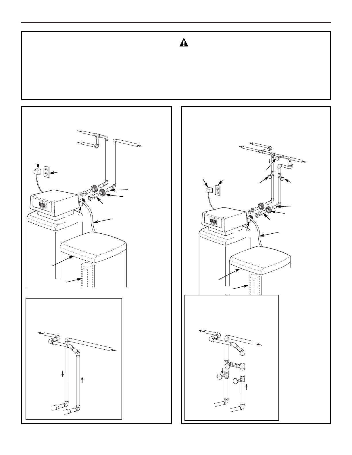
See Typical Installation Illustration. Use this as a guide
when planning your particular installation. Be sure
to direct the incoming hard water supply to the
softener valve inlet fitting. The valve is marked
IN and OUT.
5
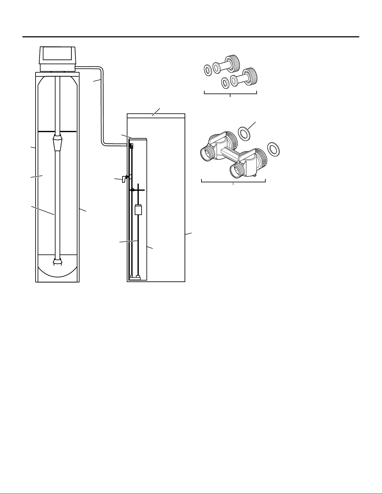
TYPICAL INSTALLATION ILLUSTRATION
Soft
water
MAIN WATER PIPE
Hard water
12V
transformer
120-volt
outlet
Brine
tank cover
SALT
GOES
HERE
Brinewell
Hard water to
outside faucets
Fig. 1
CROSSOVER
Use if water supply flows
from the left. Include single
or 3-valve bypass.
Hard
water
From
softener
outlet
Soft
water
To softener
inlet
Bypass
valve
Hard water to
outside faucets
Inlet
valve
Outlet
valve
OUTLET
MAIN WATER PIPE
Hard water
Soft
water
120-volt
outlet
12V
transformer
Brine
tank cover
Fig. 2
CROSSOVER
Use if water supply flows
from the left. Include single
or 3-valve bypass.
Hard
water
From
softener
outlet
Soft
water
To softener
inlet
NOTE: See
Drain Hose
Connections
section.
3-Valve Bypass
System
For soft water
service:
• Open the inlet
and outlet
valves
• Close the
bypass valve
For bypass hard
water:
• Close the inlet
and outlet
valves
• Open the
bypass valve
SALT
GOES
HERE
Brinewell
Brine line
OUTLET
Pipe coupler
Adapter
Union nut
Brine line
Pipe coupler
Adapter
Union nut
OPTIONAL 3-VALVE BYPASS
INSTALLATION ILLUSTRATION
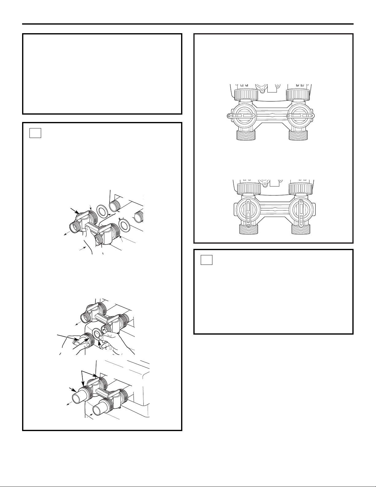
OPERATION
To bypass the Water Softener with the bypass
valve, rotate the handles clockwise so they are both
perpendicular to the flow path of the inlet and
outlet water stream, as shown below.
To return to the conditioned water or service
position, rotate the handles counterclockwise so
they are parallel to the flow path of the inlet and
outlet water stream, as shown below.
Installation Instructions
6
BEFORE YOU BEGIN
• Turn off the gas or electric supply to the water
heater, in the possibility that the water heater
may be drained while draining pipes.
• Turn off the water supply to pipes to be cut and
drain the house water pipes.
• Open both hot and cold faucets at the lowest
location possible.
INSTALL BYPASS VALVE
• Make sure there is a gasket secured inside the
inlet and outlet union nuts of the bypass. Then
assemble the union nut to the valve inlet and
outlet, hand-tightening both union nuts
simultaneously. It is not necessary to lubricate or
use sealant on the rubber gaskets or union nuts.
• Insert copper adapters through union nuts.
Place the rubber gaskets into the union nuts and
assemble to bypass valve. It is not necessary to
lubricate or use sealant on rubber gasket or
union nuts.
1
Valve outlet
Valve inlet
Inlet
union nut
MOVE THE SOFTENER ASSEMBLY
INTO INSTALLATION POSITION
Before sliding softener in position, be sure the
installation surface is level and smooth. Sharp
objects under the tank may puncture it. If needed,
place the tank on a section of 3/4″ thick (minimum)
plywood. Then, place shims under the plywood as
needed to level the softener. Slide softener into
position.
2
Outlet
union nut
Gaskets
Outlet
Inlet
Gasket
Outlet
Inlet
Outlet
Inlet
Copper
adapters
Valve outlet
Valve outlet
Valve inlet
Valve inlet
Bypass valve
Copper
adapters
Union nut
Union nut
PLUMB “IN” AND “OUT” PIPES
TO AND FROM SOFTENER
CAUTION: Observe all of the following
cautions as you connect inlet and outlet
plumbing. See Typical Installation Illustration.
• BE SURE INCOMING HARD WATER SUPPLY IS
DIRECTED TO THE SOFTENER VALVE INLET PORT.
If house water flow is from the right, use a
plumbing crossover as shown in Typical
Installation Illustration.
• With the softener in place, determine the
correct length of piping required to connect the
household plumbing to the 1″ copper adapter
on the softener. Test fit all connections.
NOTE: The softener must not support the home’s
plumbing in the vertical direction. Secure the
inlet and outlet pipes to the wall/ceiling using pipe
clamps or straps. Be certain the home’s plumbing
does not exert any force on the softener bypass.
• Remove softener from installation space.
• Disconnect copper adapters and union nuts from
bypass valve.
• Reconnect copper adapters with union nuts
and gaskets in place to home plumbing. Before
soldering adapters, slide union nuts and gasket
away from area being soldered. NOTE: Torch heat
will damage plastic parts.
• Support inlet and outlet plumbing in some manner
(use pipe hangers or clamps) to keep the weight
off of the valve fittings.
• Slide softener back into position.
• Make final connections to the bypass valve.
3
Installation Instructions
7
CONNECT AND RUN THE VALVE
DRAIN HOSE
• Check that drain port on valve body has white
tape on it. If not, apply Teflon Tape to threads
prior to installing the valve drain fitting.
• Connect valve drain fitting to valve drain port.
Tighten connection with a wrench.
• Connect 1/2″ diameter drain hose (not provided)
to the valve drain fitting. Tighten connections with
wrench.
4
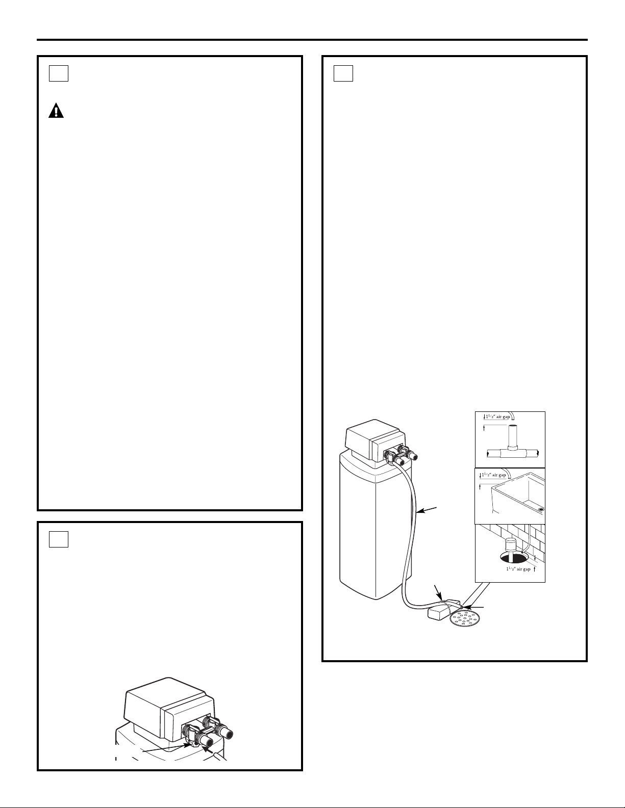
CONNECT AND RUN THE VALVE
DRAIN HOSE
(CONT.)
• Locate the other end of the hose at a suitable
drain point (floor drain, sump, laundry tub, etc.)
that terminates at the sewer. Check and comply
with local codes.
• Tie or wire the hose in place at the drain
point. High water pressure will cause it to whip
during the back-wash and fast rinse cycles of
regeneration. Also provide an air gap of at least
1-1/2″ between the end of the hose and the
drain point. An air gap prevents possible
siphoning of sewer water into the softener,
if the sewer should “back-up.”
The water softener will not work if water cannot
exit this hose during regeneration.
• Elevating the drain hose may cause back
pressure that could reduce the brine draw during
regeneration. If raising the drain line overhead is
required to get to the drain point, measure the
inlet water pressure to the softener first. For inlet
pressures between 20 and 50 psi, do not raise
higher than 8′ above the floor. For inlet pressure
above 50 psi, the drain line may be raised to a
maximum height of 14′.
4
Valve
drain
hose
FLOOR DRAIN
Tie or
wire hose
in place
1
1
⁄2″ air gap
LAUNDRY TUB
SUMP
STANDPIPE
Valve drain
hose connection
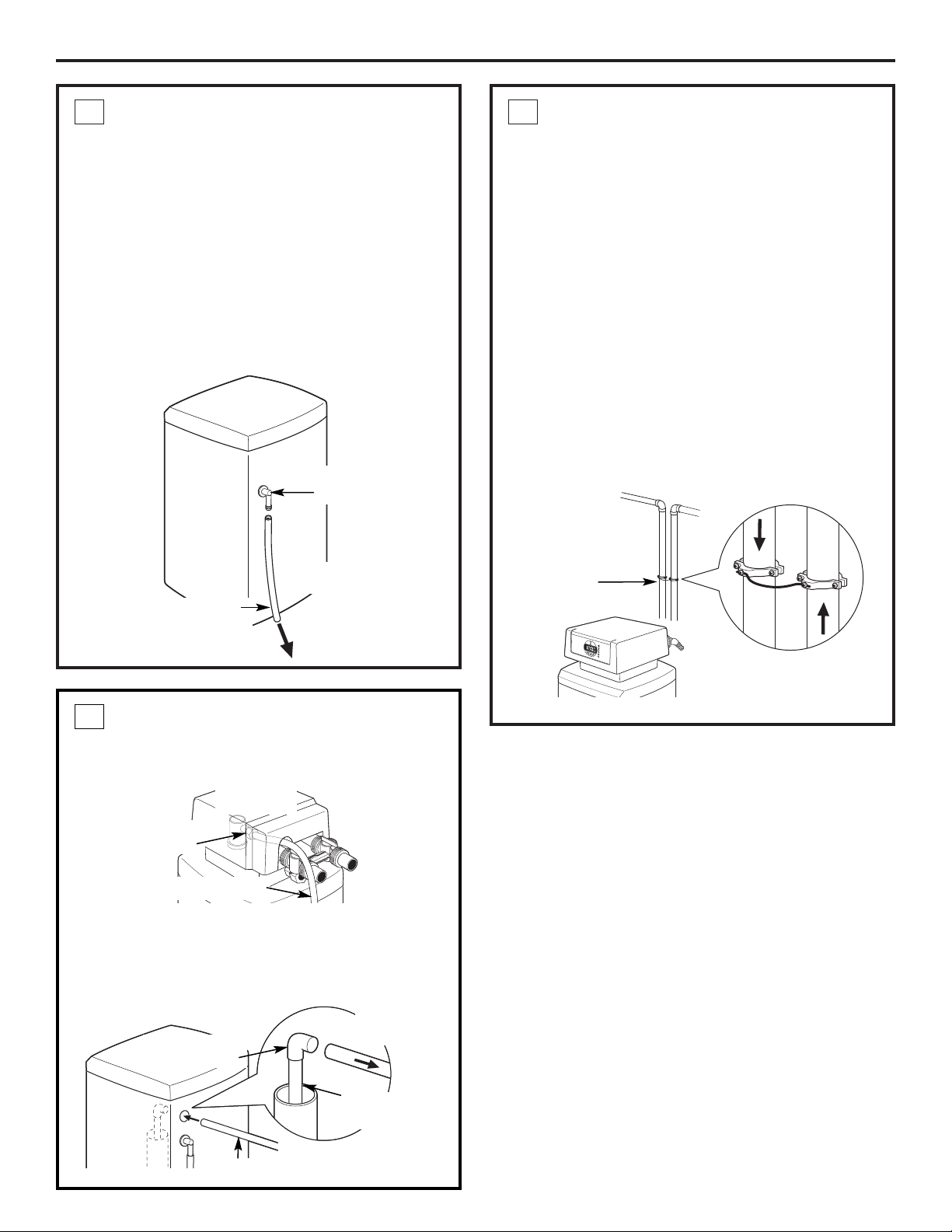
INSTALL GROUNDING WIRE
AND CLAMPS
IMPORTANT: A copper or galvanized house cold
water pipe is often used to ground electrical outlets
in the home. Grounding protects you from
electrical shock. The water softener may have
broken this ground path. To restore connection,
install UL approved grounding hardware or 6-gauge
copper wire across the softener valve, tightly
clamped, using UL approved grounding clamps at
both ends as shown. Zinc clamps should not be
used on copper plumbing. Grounding hardware is
not provided with the unit. It may be purchased
separately from your local hardware store.
NOTE: Clean copper pipe and ends of wire with
emery paper. Bare wire is recommended. If insulated
wire is used, it should be stripped 3/4″ at each end
before cleaning with emery paper.
7
Installation Instructions
INSTALL THE BRINE TANK
OVERFLOW AND HOSE
• Connect overflow drain hose to fitting on side of
brine tank.
• Locate the other end of the hose at the drain
point. DO NOT ELEVATE this hose higher than the
elbow on the brine tank.
IMPORTANT: DO NOT TEE OVERFLOW HOSE TO
VALVE DRAIN HOSE.
NOTE: This drain is for safety only. If the cabinet
(brine tank) should over-fill with water, the excess is
carried to the drain.
5
To acceptable
drain
Overflow
drain hose
Do not connect to
valve drain hose.
Hose
adapter
Ground
Clamp
From
valve
outlet
To valve
inlet
BRINE TUBING CONNECTION
Connect brine tube to clear air check assembly on
the main valve:
• Route brine tube through 1″ hole in brine tank
above hose adapter.
• Connect tubing to 90° fitting on top of float
assembly. Press in firmly to fully seat in fitting.
6
Brine tube
Brine tube
connection
To valve
assembly
8
Float
assembly
Brine tubing
Brine tube
connection
Valve
assembly
OPEN WATER SUPPLY
With the plumbing, drain line and overflow
connections completed, slowly open the water
supply, allowing the lines to pressurize.
NOTE: The optional bypass should still be in bypass
mode as shown.
1
Installation Instructions
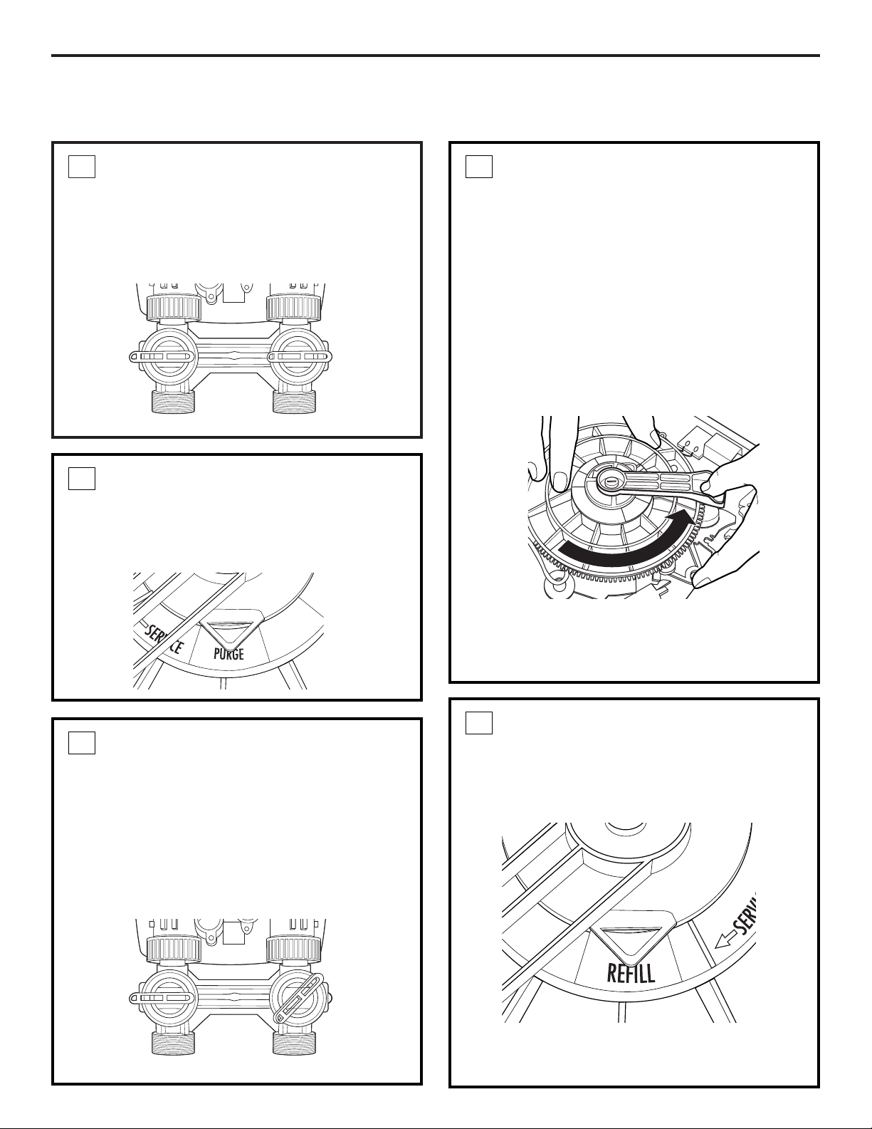
START-UP RINSING PROCEDURE
(BYPASS VALVE IS OPTIONAL)
Outlet
Inlet
ADVANCE THE CONTROL VALVE
With the transformer unplugged, manually advance
the control valve by depressing the drive gear and
rotating the main system gear to the purge position
(see Step 4).
2
RUN THE WATER
After the 20-minute purge cycle, manually advance
the main gear to the backwash cycle and allow to
run for a minimum of 10 minutes.
After 10 minutes during the backwash cycle, open
both the inlet and outlet valves on the bypass to the
fully opened position.
NOTE: When advancing the main gear manually
while under water pressure, it is normal for the gear
to encounter resistance as the valve chambers
depressurize. If resistance occurs, pause five
seconds to allow the valve to depressurize
before advancing to the next step.
Advance the gear in the counterclockwise direction
only. Damage will occur if advanced in the opposite
direction.
4
FILL BRINE TANK
After the ten-minute backwash cycle, manually
advance the control valve to the brine refill position
for ten minutes, allowing water to flow into the
brine storage tank.
Once water begins to flow into the tank, fill the
brine tank with a minimum of 80 lbs. of salt pellets.
5
PURGE THE SYSTEM
Slowly open the inlet valve (only) on the bypass
valve to the half-opened position, allowing the
system to pressurize. It is normal to hear air
blowing to the drain during this procedure.
Once the air clears and water begins to run to
the drain, open the inlet valve (only) to the full open
position and allow the water to run to the drain in
purge for a minimum of 20 minutes.
3
Outlet
Inlet
9
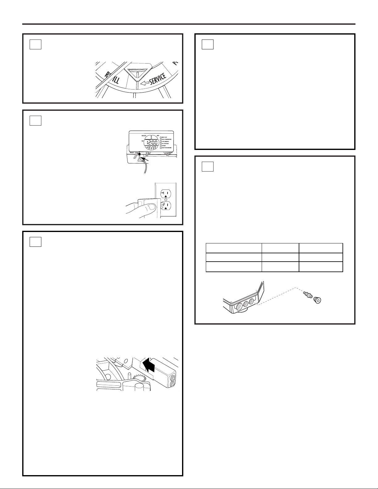
INJECTOR SELECTION
• The injector is critical to the proper flow through
the resin tank during the regeneration cycle. The
injector supplied with the unit from the factory is
applicable to installations with supply water
pressure up to 70 psi.
• If supply water pressure is greater than 70 psi,
injector assembly WS15X10059 should be
installed.
9
Installation Instructions
ADVANCE CONTROL VALVE TO
SERVICE POSITION
After the ten-minute
refill time, manually
advance the control
valve to the service
position.
6
CONNECT TO ELECTRICAL POWER
• The softener works on 12 volt-
60Hz electric power. The
included transformer changes
standard 120-volt AC house
power to 12 volts DC. Connect
transformer to control panel.
Plug is located on the bottom
left of the control panel. Plug
the transformer into a 120-
volt outlet only. Be sure the
outlet is always live so it can
not be switched off by mistake.
7
INSTALL 9V BATTERY FOR BATTERY
BACKUP FEATURE
(CONT.)
To install a battery:
1. Remove the control valve cover.
2. The battery pocket is located in the upper left
corner of the control as shown.
3. Connect the battery, matching up negative and
positive posts.
4. Insert battery into holder located on the back of
the control panel. Make sure terminal wires are
routed away from the valve gears.
8
Injector
Injector cap
INSTALL 9V BATTERY FOR BATTERY
BACKUP FEATURE
Your softening system has a battery backup feature
that allows the control to continue monitoring
water flow and maintain the proper time of day
during short power outages. The control uses a
standard 9-volt battery (not supplied).
During a power outage, the display will be turned
off and the motor will not run, but the control will
continue to monitor water flow and time. If power is
out and a regeneration is needed, the regeneration
will be delayed until power is restored. If power is
lost during the regeneration, the control will resume
the regeneration when power is restored.
While batteries may
last for over a year, it
is recommended that
you replace the
battery every year.
During an interruption in power supply, a typical
new 9-volt alkaline battery provides approximately
40 hours of power for the control.
If there is a power outage, after power is restored,
verify that the time in the control is correct. If it is,
system is OK. If time is incorrect, set the correct
time in the control and replace the 9-volt battery.
If system has been without power for over 24
hours, initiate an immediate regeneration cycle
by pressing the REGEN button.
8
10
Water Pressure Injector Part Number
20–70 psi 5 bumps WS15X10060
70–125 psi 4 bumps WS15X10059
Connect
transformer
to control
panel
11
Installation Instructions
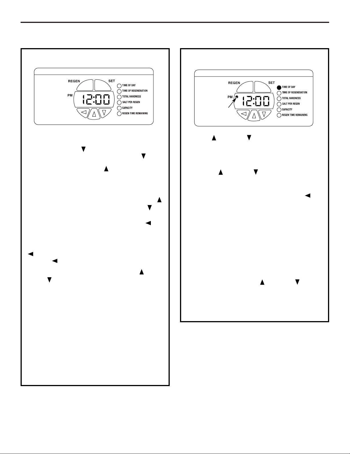
PROGRAMMING THE CONTROL
PROGRAMMING THE CONTROL
The green indicator lights up next to the name of
the active control setting.
Pressing the DOWN button displays the settings
in order. By continuing to press the DOWN
button, the settings start over, beginning with the
time of day. Pressing the UP button displays the
settings in reverse order.
To change the settings, press the SET button on
the top right. A digit on the display will start to flash.
If you want to change this number, press the UP
button to increase the number or the DOWN
button to decrease the number.
When the number is correct, press the LEFT
button. The digit to the right will stop flashing and
the next digit to the left starts flashing.
To skip the number without changing, press the LEFT
button. When you reach the far left digit, press
the LEFT button to return to the digit on the right.
NOTE: If you press and hold either the UP or
DOWN button for more than 1 second, the
flashing number will increase or decrease at ten
counts per second.
You can only change the flashing digit. Continue
changing numbers until you reach the desired
setting. Press the SET button. The numbers stop
flashing and the control accepts the new settings.
After approximately 30 seconds, the control starts
alternating the display between TIME OF DAY and
CAPACITY.
NOTE: If the new setting is not accepted because it
was outside the allowable range, the old value will
be displayed. Refer to the table guides for correct
settings.
SET PRESENT TIME OF DAY
Press UP or DOWN button to select TIME OF
DAY.
1. Press the SET button. The display will show the
time of day with the minutes blinking.
2. Press UP or DOWN button to set. The UP
button advances the digit; the DOWN button
moves the digit in reverse.
When the number is correct, press the LEFT
button. The digit to the right will stop flashing and
the next digit to the left starts flashing. You can only
change the flashing number.
If the present time is between noon and midnight,
be sure PM indicator light is on. If the present time is
between midnight and noon, be sure PM indicator
light is off.
To change AM/PM, advance the far left digit. The
digit will alternate between 0 and 1. As the digit
alternates, the PM light will turn on and off.
NOTE: Each press of an UP or DOWN button
changes the digit by one minute. Holding the button
changes the digit at a rapid rate.
3. When the present time is correct, press SET to
accept.
PM Indicator
light
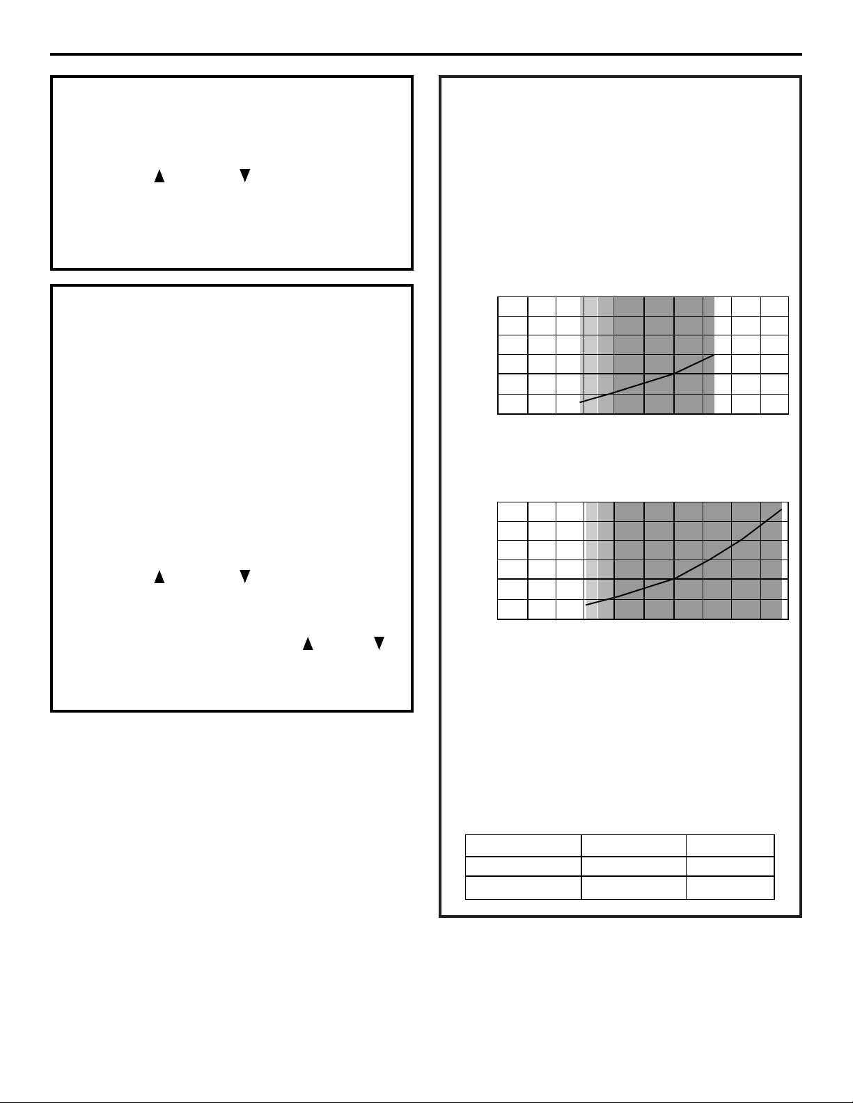
SALT PER REGEN AND CAPACITY
These two settings are required to provide the most
efficient operation of the system in your installation.
Salt efficiency is improved by regenerating part of
the capacity. For example, the GNPR40 has 37,100
grains of capacity. It is more efficient to regenerate
20,000 grains of capacity more frequently than
waiting and regenerating the complete 37,100
grains.
Both SALT PER REGEN and CAPACITY are
determined based on the chart on page 13.
FOR CALIFORNIA INSTALLATIONS:
• California regulations require the control setting
to yield 4,000 grains of capacity per pound of salt.
To meet these requirements, the SALT PER REGEN
and CAPACITY must be set no higher than
indicated below:
12
Installation Instructions
TIME OF REGENERATION
The system has a default setting of 2:00 a.m.
To change:
• Use the UP or DOWN button to select a new
time for regeneration.
• Use procedure in SET PRESENT TIME OF DAY.
• Press the SET button to accept.
TOTAL WATER HARDNESS
Water hardness is the hardness of the supply water
to the house in grains per gallon. The system has a
default setting of 25 grains/gallon.
A water test should be performed at the time
of installation to determine your water hardness
(grains/gallon). You can get the grains per gallon
(gpg) hardness of your water supply from a water
analysis laboratory. If you are on a municipal
supply, call your local water department. If your
report shows hardness in parts per million (ppm),
simply divide by 17.1 to get the equivalent number
of grains per gallon.
To change:
• Use the UP or DOWN button to select total
water hardness.
• Press the SET button.
• Change the digits by using the UP , DOWN
or LEFT button.
• Press the SET button to accept.
Model Capacity Default Salt Default
GNPR40L 16.5 KGr 4.0 lbs
GNPR48L 15.2 KGr 3.6 lbs
GNPR48L
Capacity (1,000 grains)
Salt Setting (lbs)
30
25
20
15
10
5
0
0 1020304050
GNPR40L
Capacity (1,000 grains)
Salt Setting (lbs)
30
25
20
15
10
5
0
0 1020304050
SYSTEM CAPACITY INPUTS
40
GNPR40L certified capacity at salt setting
48
GNPR48L certified capacity at salt setting
NOTE: The 3.0 lbs salt setting (GNPR40L) and the
3.6 lbs salt setting (GNPR48L) are certified using
the 5 bump injector. The 7.5 lbs (GNPR40L), 15 lbs
(GNPR40L), 9 lbs (GNPR48L) and 18 lbs (GNPR48L)
are certified using the 4 bump injector.
13
Installation Instructions
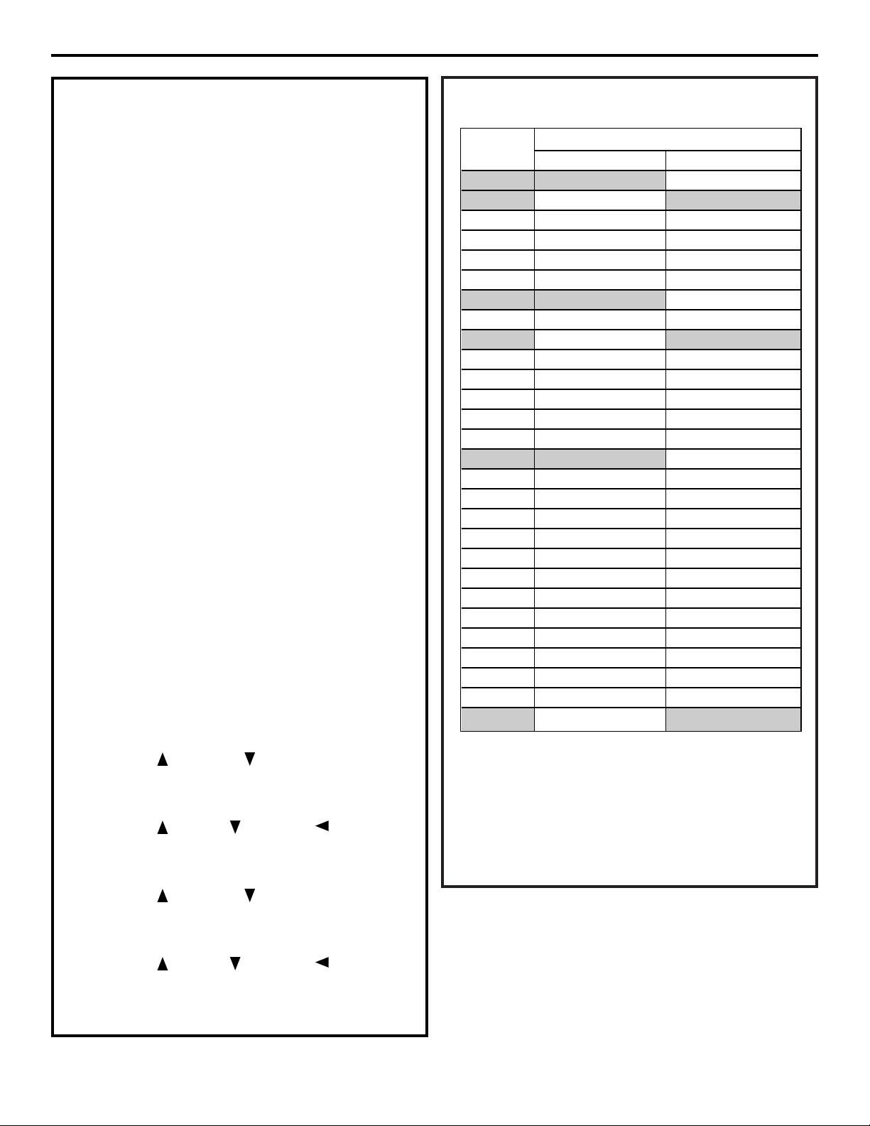
SALT PER REGEN AND CAPACITY (CONT.)
NOTE: Both SALT PER REGEN and CAPACITY inputs
must be based on the SYSTEM CAPACITY INPUTS
CHART.
How to determine correct salt dosage and
capacity:
The correct salt dosage and capacity are determined
based on the family size and water hardness. Use the
following procedure and example:
• Daily Water Usage = number of persons in
household x 80 gallons
For a family of 3
Daily Water Usage = 3 x 80 = 240 gallons/day
• Water Hardness – have the water tested or call
your local water company. For this example, 20
grains is assumed.
• Calculate total grains used per day =
gallons/day x hardness = grains/day
240 gallons/day x 20 grains = 4,800 grains/day
• Water softener should be set to regenerate every
5 days.
Req Capacity = 5 days x 4,800 grains/day = 24,000
• Use SYSTEM CAPACITY INPUT table to select
capacity and determine lbs of salt per regeneration.
For GNPR40 use setting at 24,000 grains.
• Program the control:
Capacity: 24,000 grains
Lbs of Salt: 7.0
If water supply has a high level of sediment or iron,
set system to regenerate every 3 days:
• Use the UP or DOWN button to select SALT
PER REGEN.
• Press the SET button.
• Use the UP , DOWN and LEFT buttons to
select SALT PER REGEN amount.
• Press the SET button to accept.
• Use the UP or DOWN button to select
CAPACITY.
• Press the SET button.
• Use the UP , DOWN and LEFT buttons to
select correct capacity.
• Press the SET button to accept.
Example
of Lbs of Salt
req. per regen
CAPACITY (x 1,000)
GNPR40L GNPR48L
3.0 14.1
40
N/A
3.6 15.5 15.2
48
4.0 16.5 15.5
5.0 19.0 18.0
6.0 22.0 21.0
7.0 24.0 23.5
7.5 24.4
40
24.3
8.0 25.6 25.0
9.0 27.9 26.1
48
10.0 30.0 30.0
11.0 31.9 31.5
12.0 33.6 33.0
13.0 35.1 34.0
14.0 36.4 35.2
15.0 37.1
40
36.0
16.0 N/A 37.0
17.0 N/A 38.0
18.0 N/A 39.8
19.0 N/A 41.0
20.0 N/A 41.5
21.0 N/A 42.0
22.0 N/A 43.0
23.0 N/A 44.0
24.0 N/A 45.2
25.0 N/A 45.9
26.0 N/A 46.5
27.0 N/A 47.2
28.0 N/A 48.9
48
Installation Instructions
14
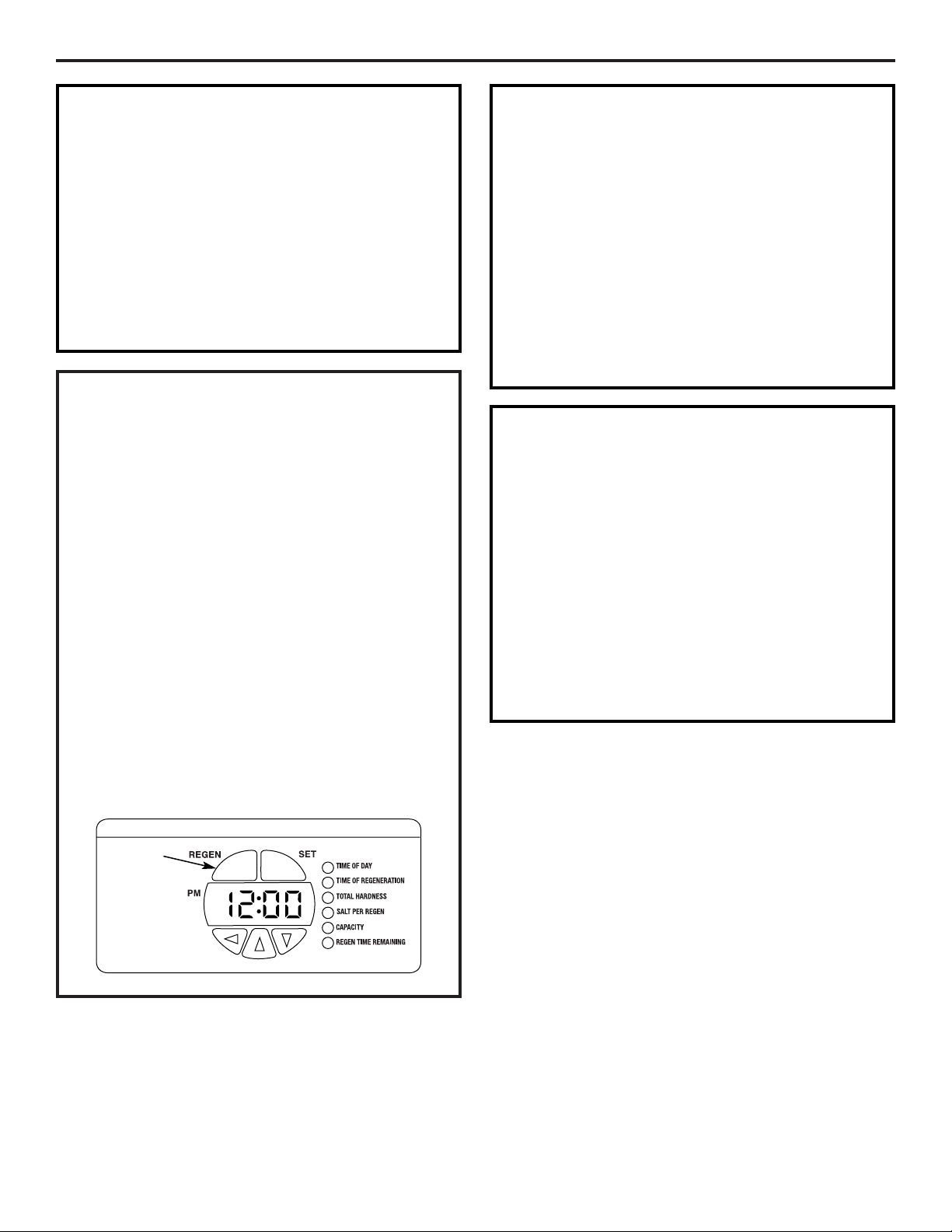
MANUAL REGENERATION
Occasionally you may find it necessary to initiate a
manual regeneration. This is done by pressing the
REGEN button on the front of the display. When you
press the REGEN button, the control performs a full
regeneration of the water conditioner immediately.
In the event the system is allowed to run out
of salt, it will be necessary to run “Back to Back”
regenerations. This can be done easily by pressing
the REGEN button one time, waiting at least one
minute and pressing the REGEN button again.
NOTE: The second regeneration will begin
immediately after the first is completed.
“Back to Back” regenerations are necessary if full
exhaustion occurs due to low regenerate levels or
system malfunction. The system works on a highly
efficient proportionate-brining method. When the
system is not aware of the lack of proper regenerate
(salt), a larger portion of the resin bed becomes
exhausted.
REGEN
button
NORMAL OPERATION
The control will cycle between TIME OF DAY and
CAPACITY about every 10 seconds, as indicated by
the green indicator light.
Capacity in Normal Operation mode is the gallons
of water available until the next regeneration cycle.
During a regeneration cycle, the control will cycle
between TIME OF DAY and REGEN TIME REMAINING.
REGEN TIME REMAINING is the number of minutes
until the regeneration cycle is complete.
ERROR CODES
This system continuously monitors itself and
displays an error message if it detects something
wrong. This typically happens when the valve has
not advanced through the regeneration cycle
properly.
When an error is detected, the display shows the
letters “Err” with a number from 1 to 4. The table on
page 24 describes each error, the cause of the error
and the solutions.
To clear the error from the display, press any button
on the control. If the error still exists, the control will
display the error message again after 30 seconds.
SOUNDS YOU WILL HEAR
During the regeneration cycle, the softener makes
several sounds. These sounds are normal.
• Clicking sound – This occurs as the valve assembly
advances. It is the opening and closing of the
valve ports.
• Harmonic sound – As the valve transitions
between cycles in regeneration, a high-pitched
harmonic noise may be heard for a few seconds.
• Water flow sound – In the backwash and purge
portions of the regeneration, water flow is very
high – 2–3 gpm. This is required to flush the tank
of accumulated minerals and sediments.
15
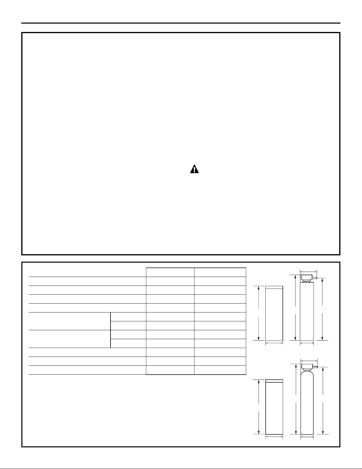
SPECIFICATIONS/DIMENSIONS
Installation Instructions
These systems conform to WQA NSF/ANSI 44 for the specific capacity claims as verified and substantiated by test data.
* Testing was performed using pellet grade sodium chloride as the regenerant salt.
** Efficiency rating is valid only at the lowest stated salt dosage. These softeners were efficiency rated according to
WQA NSF/ANSI 44.
*** Extent of iron removal may vary with conditions. The capacity to reduce clear water iron is substantiated by WQA
test data. State of Wisconsin requires additional treatment if water supply contains greater than 5 ppm clear water
iron. Use of Diamond Crystal
®
Red•Out
®
or Super Iron Out
®
will improve iron removal. Refer to Cleaning Iron Out
of the Water Softening System section.
SANITIZING PROCEDURES
To complete the installation, do the following
sanitizing procedures.
Care is taken at the factory to keep your water
softener clean and sanitary. Materials used to make
the softener will not infect or contaminate your water
supply and will not cause bacteria to form or grow.
However, during shipping, storage, installation and
operation, bacteria could get into the softener. For
this reason, sanitizing as follows is suggested when
installing.
NOTE: Sanitizing is recommended by the
Water Quality Association for disinfecting.
1. Be sure to complete all installation steps, including
programming the control.
2. Pour about 3/4 oz. (1
1
⁄2 tablespoons) of common
5.25% unscented household bleach (Clorox, Linco,
Bo Peep, White Sail, Eagle, etc.) into the brinewell.
Refer to illustration on page 5.
3. IMPORTANT: Press and hold for 3 seconds the
faceplate REGEN button to start an immediate
regeneration. The indicator light will alternate
between TIME OF DAY and REGEN TIME
REMAINING. The bleach will be drawn
through the water softener, and out the drain.
This process takes approximately 3 hours.
4. If, after sanitization, water from the house
faucet tastes salty or has a slight color, this is a
preservative from the resin tank. Turn on the cold
soft water faucets and drain for a few minutes or
until clear.
NOTE: When the sanitizing regeneration is over,
all remaining bleach is flushed from the conditioner
and your house COLD water supply is fully soft
immediately. However, your water heater is filled
with hard water and as hot water is used, it will refill
with soft water. When all the hard water is replaced
in the water heater, hot only and mixed hot and cold
water will be fully soft. If you want totally soft water
immediately, after the above regeneration, drain the
water heater until the water runs cold.
WARNING: If you do drain the water
heater, use extreme care as the hot water could
cause burns. Turn the water heater off prior to
draining.
GNPR40L GNPR48L
Resin Tank Size 10x44″ 12x48″
Resin Volume 1.25 ft
3
1.50 ft
3
Refill Controller 0.35 gpm 0.35 gpm
Backwash Controller 2.8 gpm 2.8 gpm
Brine Tank Size 15x40″ 15x40″
Capacity 350 lbs 350 lbs
Operation Temperature Min. 34° 34°
Max. 100°F 100°F
Flow Rate 15.2 gpm 18.0 gpm
Pressure Drop 15.0 psi 15.0 psi
Maximum Flow to Drain 4.0 gpm 3.5 gpm
C
L
47″
40
1
⁄4″
15″
10″
14
1
⁄2″
44
40
1
⁄4″
15″
51
1
⁄4″
C
L
12″
15
1
⁄4″
48
50″
54
1
⁄4″

About the water softener system.
Service
When the water softening system is providing
soft water, it is called “Service.” During service,
hard water flows from the house main water pipe
into the water softening system. Inside the water
softening system resin tank is a bed made up of
thousands of tiny, plastic resin beads. As hard
water passes through the bed, each bead
attracts and holds the hard minerals. This is
called ion-exchanging. It is much like a magnet
attracting and holding metals. Water without
hard minerals (soft water) flows from the water
softening system and to the house pipes.
After a period of time, the resin beads become
coated with hard minerals and they have to be
cleaned. This cleaning is called regeneration. The
regeneration cycle is started at 2:00 AM (factory
setting) by the water softening system control,
and consists of five stages or cycles. These are
FILL, BRINING, BRINE RINSE, BACKWASH and
FAST RINSE.
For emergency needs, hard water is available
to the home during the regeneration cycles.
However, you should avoid using HOT water
because the water heater will fill with the hard
water.
Automatic Hard Water Bypass During Regeneration
Fill
Salt dissolved in water is called brine. Brine is
needed to clean the hard minerals from resin
beads. To make the brine, water flows into the
salt storage area during the fill stage.
Brining
During brining, brine travels from the salt storage
area into the resin tank. Brine is the cleaning
agent needed to remove hard minerals from the
resin beads. The hard minerals and brine are
discharged to the drain.
The nozzle and venturi create a suction to move
the brine, maintaining a very slow rate to get the
best resin cleaning with the least salt.
Brine Rinse
After a pre-measured amount of brine is used,
the brine valve closes. Water continues to flow in
the same path as during brining, except for the
discontinued brine flow. Hard minerals and brine
flush from the resin tank to the drain.
Backwash
During backwash, water travels up through
the resin tank at a fast flow rate, flushing
accumulated iron, dirt and sediments
from the resin bed and to the drain.
Fast Rinse
Backwash is followed by a fast flow of water
down through the resin tank. The fast flow
flushes brine from the bottom of the tank,
and packs the resin bed.
After fast rinse, the water softening system
returns to soft water service.
16
17
ge.com
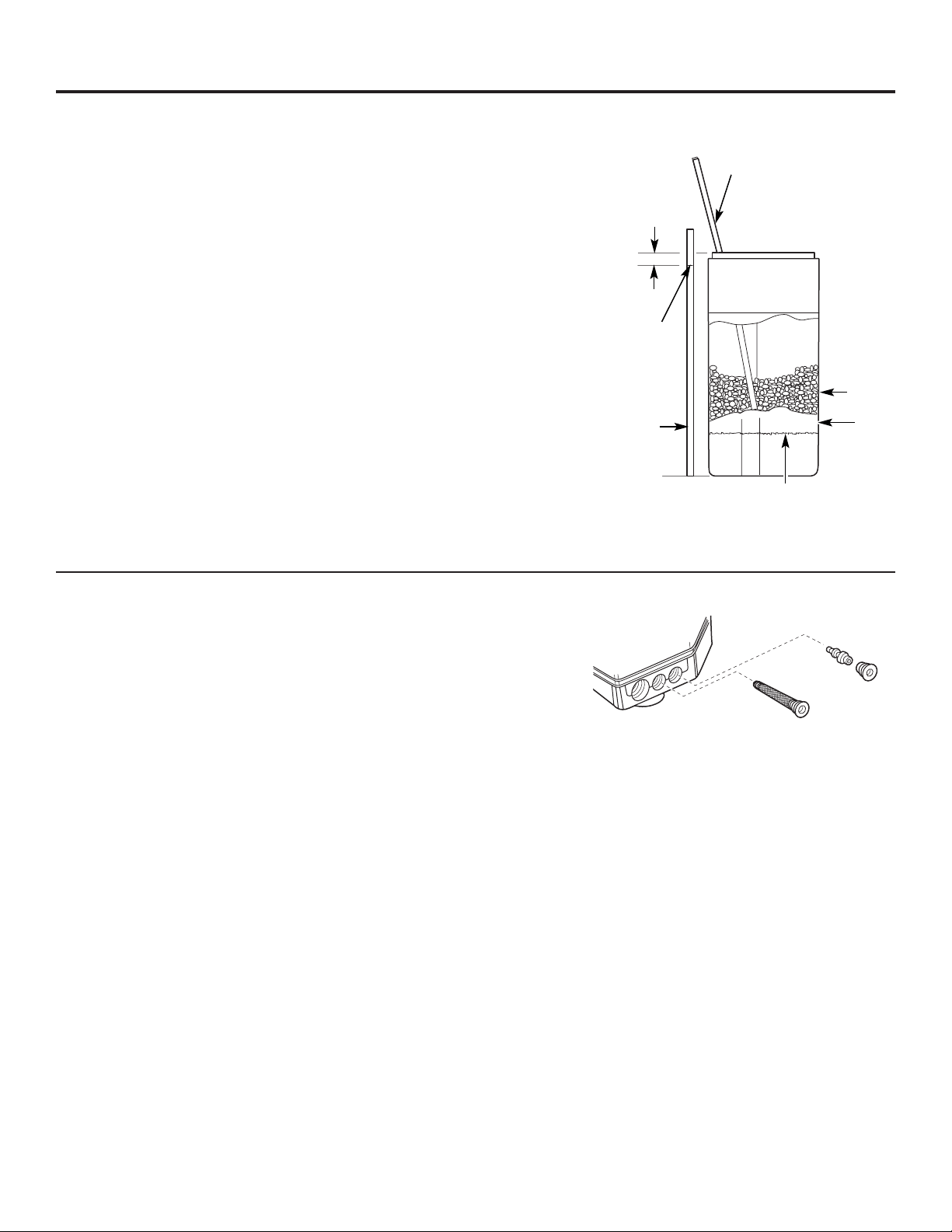
Breaking a Salt Bridge
Sometimes, a hard crust or salt bridge forms in
the salt storage area. It is usually caused by high
humidity or the wrong kind of salt. When the salt
bridges, an empty space forms between the
water and salt. Then salt will not dissolve in the
water to make brine.
If the brine tank is full of salt, it is hard to tell
if you have a salt bridge. Salt is loose on top, but
the bridge is under it. The following is the best
way to check for a salt bridge.
Salt should be loose all the way to the bottom of
the tank. Take a broom handle or like tool, and
carefully push it down into the salt, working it up
and down. If the tool strikes a hard object (be
sure it’s not the bottom or sides of the tank), it’s
most likely a salt bridge. Carefully break the
bridge with the tool. Do not pound on the walls
of the tank.
If the wrong kind of salt made the bridge, take it
out. Then fill the tank with nugget or pellet salt
only. In humid areas, it is best to fill with less salt,
more often to prevent a salt bridge from forming.
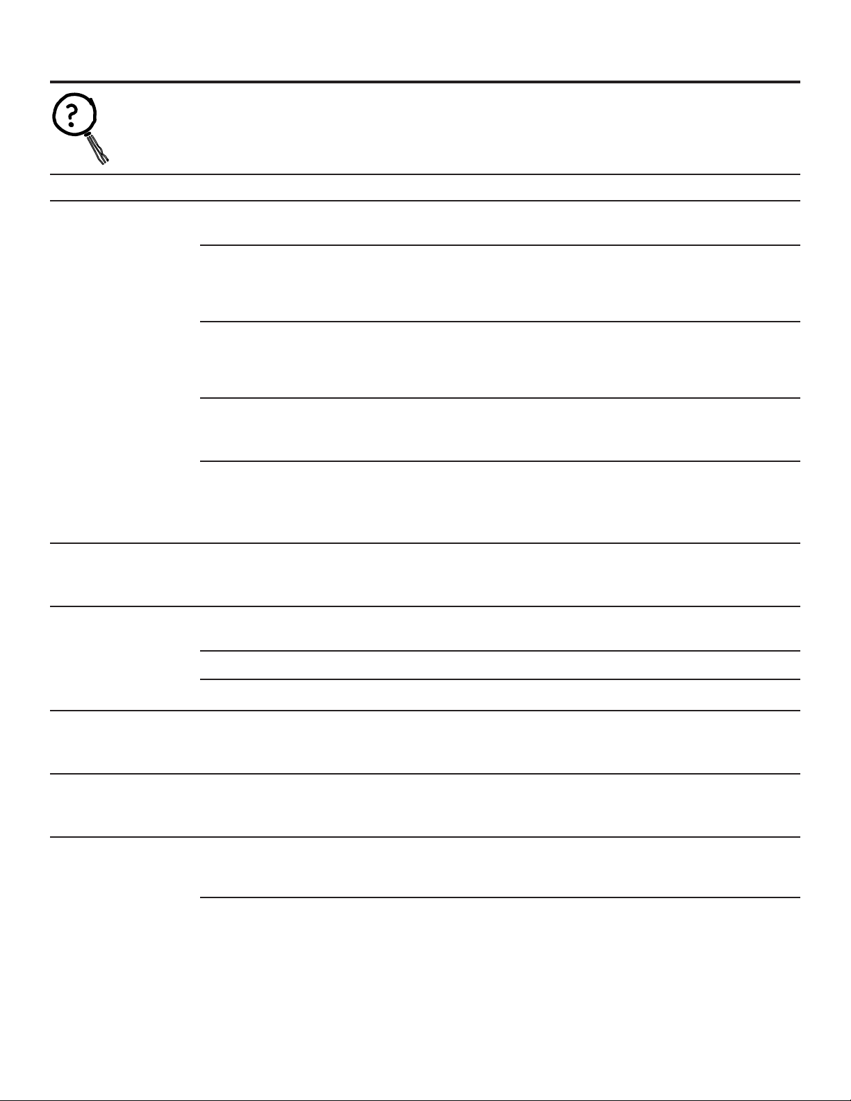
A clean injector and screen is needed for the
water softening system to work properly. This
small unit makes the suction to move brine from
the brine tank storage area to the resin tank
during regeneration. If it becomes plugged with
sand, dirt, etc., the water softening system will
not work and you will get hard water. This will
be evident by a high level of water in the brine
tank—over 4″ when the system is in service
mode.
TO CLEAN:
•Put system in Bypass mode and relieve water
pressure.
•Remove injector screen (a flat-head screwdriver
is required).
•Remove injector cap and injector (needle nose
pliers are required).
•Clean and flush thoroughly.
•Check for damage.
•Reassemble injector and injector screen.
•To check proper operation, see page 30,
Checking the Brine Draw and Refill Function.
•Initiate REGEN cycle to restore resin bed.
A back-to-back regeneration is suggested.
Excess water in the brine tank will be removed.
Cleaning the Injector and Screen
Push tool into salt
bridge to break
Pencil
mark
Broom
handle
Salt
Salt
bridge
Water level
1″–2″
Injector
Injector cap
Injector
screen
Injector screen and cap installation

Care and cleaning of the water softening system.
Brine (salt dissolved in water) is needed for each
and every regeneration. The water for making
brine is metered into the salt storage area by
the water softening system valve and control.
However, you must keep the tank supplied
with salt.
Use clean water softening salts only, at least
99.5% pure. NUGGET, PELLET or coarse SOLAR
salts are recommended. Do not use rock, block,
granulated or ice cream making salts. They
contain dirt and sediments, or mush and cake,
and will create maintenance problems.
CAUTION:
Water softening salt
with iron removing additives: Some salts
may have an additive to help the water
softening system handle iron in the water
supply. Although this additive may help to
keep the water softening system resin clean,
it may also release corrosive fumes that
weaken and shorten the life of some water
softening system parts. GE recommends
using only Diamond Crystal
®
Red•Out
®
brand salt.
Checking the Salt Storage Level and Refilling
Your water softening system takes hardness
minerals (calcium and magnesium) out of
the water. Also, it can control some (see the
Specification Guidelines section) “clear water”
iron. With clear water iron, water from a faucet
is clear when first put into a glass. After 15 to 30
minutes, the water begins to cloud or turn rust
colored. A water softening system will not
remove any iron that makes the water cloudy
or rusty as it comes from the faucet (called red
water iron). To take red water iron out of water,
or over the maximum of clear water iron,
an iron filter or other equipment is needed.
GE recommends using only Diamond Crystal
®
Red•Out
®
brand salts with Iron Fighter
®
additive
to help keep the resin bed clean of clear iron. If
your water supply has clear water iron, periodic
resin bed cleaning is needed. GE recommends
using Super Iron Out
®
brand resin bed cleaner
to thoroughly clean your resin bed if your iron
content is high. Clean the bed at least every six
months, or more often if iron appears in the soft
water between cleanings.
IMPORTANT: It is important to mix the resin bed
cleaner with water (following the manufacturer’s
instructions), pour it into the brinewell tube
(see page 5) and regenerate the softener
immediately. Do not pour the resin bed cleaner
in with the salt, as it will not be as effective in
cleaning the resin, and can cause damage to
the softener if it is left in the brine tank for an
extended period due to the corrosive gases
that are formed.
The control has an adjustable backwash
cycle. The backwash can be lengthened to
better flush the resin bed from high sediment
or iron situations. See the Advanced Control Setting
section or consult an installer.
Also set LBS OF SALT and CAPACITY so the system
will regenerate about every 3 days. See page 13.
Cleaning Iron Out of the Water Softening System
18

19
Troubleshooting Tips
Save time and money! Review the chart on these pages
first and you may not need to call for service.
Problem Possible Causes What To Do
No soft water Faucet or fixture where sample was •
To conserve salt, the installer
may have isolated some fixtures
taken not plumbed to soft water.
(outside faucets, toilets, etc.)
from soft water. From the outlet
NOTE:
Be sure sample is from a faucet of the water softening system, trace the water flow path,
that does not mix soft and hard water. in house plumbing. If soft water is not directed to a faucet
For example, a single lever kitchen faucet, or
fixture where wanted, consult a plumber.
if the cold side is plumbed to hard water.
No salt in the brine tank or • Check for a salt bridge or, if the
tank is empty, refill with
salt bridged recommended salt. Press (for 3 seconds) the REGEN
button to start an immediate regeneration and restore
soft water supply. See page 17, Breaking a Salt Bridge.
Transformer unplugged at wall outlet or
• Check for a loss of electrical power to the water softening
power cable to softener not connected. system, due to any of these conditions and correct as needed.
Fuse blown or circuit breaker popped With the power supply restored, observe the faceplate time
on circuit to electrical outlet. display and read Programming the Control section.
Electrical outlet on a circuit that can
NOTE: The electrical outlet for the softener should be
continuously
be switched off
live
so it cannot be accidentally switched off.
Manual bypass valve in bypass position • Be sure the flange on the bypass valve knobs are in line with
the pipes.
Valve drain hose pinched, plugged, •
Any restriction in this drain hose
may prevent proper
elevated too high or otherwise
operation of the
nozzle and venturi and reduce or prevent
restricted brine draw during regeneration.
Injector and injector screen dirty, • This will be evident by a high level of water in the brine tank.
incorrectly assembled or damaged Water level will be greater than 4″ when the system is in the
service position.
• Refer to Cleaning the Injector and Screen
instructions.
With water pressure to the
water softening system off, remove
the injector and injector screen. Thoroughly clean and flush.
Check for any damage. Reassemble to valve assembly.
If resin bed is fully exhausted, for • Complete “back to back” regenerations. Initiate Regeneration
example, after a malfunction, one cycle, wait 1 minute, then press REGEN again.
regeneration cycle may not fully See page 14.
restore capacity
NO SOF
T WATER – Most Common Problems:
Check the following before calling for service:
•
Not enough salt—brine tank should be at least 1/3 full.
•
Bypass valve in “Bypass” position—flange on knobs should be in line with pipes
(see page 6).
•
Hardness setting too low. Check hardness setting and adjust. Verify hardness of supply
water—from local water company, water test or call the GE Answer Center.
•
Salt Bridge—salt solidifies above water level so that brine water is not in contact with
salt. See the Breaking a Salt Bridge section.
Before you call for service…
ge.com
Problem Possible Causes What To Do
Water hard sometimes Using hot water while the water • Avoid using hot water during water softening system
softening system is regenerating regeneration because the water heater will refill with hard water.
Control HARDNESS number setting • Press the SET button to enter a new value. Be sure the
too low number shown is the same as the actual grains per gallon
hardness of your water supply. See the Programming
the Control section if a change in the setting is needed.
Grains of hardness in your water •
Water hardness can change
over time, especially in well water.
supply have increased To check, have the water tested by a water analysis laboratory
or call your local water department. Adjust the hardness
number setting as needed.
System capacity inputs, Salt per •
See Salt per Regen and Capacity section so system will
Regeneration and Capacity set too low
regenerate about every 5 days. See instructions on pages 12
and 13.
If resin bed is fully exhausted, for •
Complete “back to back” regenerations. Initiate Regeneration
example, after a malfunction, one
cycle, wait 1 minute, then press REGEN again.
regeneration cycle may not fully
See page 14.
restore capacity
Water feels slippery Absence of hardness minerals • This is normal. Hardness in water gives it the abrasive feel
after installation of you may have been accustomed to. The slippery feel is the
water softening system clean feel of soft water.
Water softening system Water softening system is a • Does not use much salt to regenerate—very efficient.
not using any salt “demand” unit
Possible salt bridge • See the Breaking a Salt Bridge section.
Possible plugged injector and screen • See the Cleaning the Injector and Screen section.
Water is blue color Acidic water in copper plumbing • Have the water tested at once.
after water softening
system was installed
Cloudiness on glassware Combination of soft water and • This is called etching and is permanent. To prevent this
(automatic dishwashers) too much detergent from happening, use less detergent if you have soft water.
Wash glassware in the shortest cycle that will get them clean.
Excessive/high level Valve drain hose pinched, • Any restriction in this drain hose may prevent proper
of water in brine tank plugged, elevated too high operation of the injector and screen and reduce or prevent
or otherwise restricted brine draw during regeneration.
Injector or injector screen dirty • See the Cleaning the Injector and Screen section, page 17.
With water pressure to the water softening system off,
remove the injector and injector screen. Thoroughly clean
and flush. Check for any damage. Reassemble to valve
assembly.
Before you call for service…
20
Troubleshooting Tips

21
Problem Possible Causes What To Do
Salty tasting or Unit not sanitized • Complete the Sanitizing Procedures on page 15.
brown/yellow colored
• At completion of regeneration cycle (approx. 2 hrs), run water
water after installation
from faucets to purge the salty water.
Low water pressure Check pressure.
• Drain height 8′ or less, pressure should be minimum of 20 psi.
• Drain height above 8′, pressure should be minimum of 50 psi.
Restricted drain hose • Clean and reconnect drain line.
• Check for kinks in drain line.
Brown/yellow Unit was idle for a period of time • Complete the Sanitizing Procedures on page 15.
colored water
Sounds you might hear Running water from the unit • This is normal. High water flows in backwash cycle, flushes
during regeneration into a drain during regeneration minerals and sediments from resin tank.
cycle
Harmonic noises during regeneration • This is normal.
Clicking • This is normal. This is the sound of various valves opening and
closing as valves cycle through regeneration cycle.
Water has air bubbles Air in system after installation • Will go away after it runs for a while.
and is cloudy
ge.com
Advanced programming and troubleshooting section.
WARNING: Advanced programming should
only be performed by a qualified technician.
This section was designed for the use of water treatment
professionals. Default settings are based on water conditions
at a typical installation. Before making any changes, consult
a water treatment professional, as incorrect settings may
result in a system malfunction. Programming the control is
not covered under the warranty.
To access advanced programming, simultaneously hold down
the UP and DOWN buttons. This will allow you to enter
advanced programming settings P6 through P19 (see table
below).
Advanced Programming Parameters
Minimum Units
Parameter Description Range Increments of Measure Notes
P6 Refill controller 1–99 1 gpm 0.33 gpm, both models
P7 Brine draw value 1–99 1 Minutes 40L – 15 and 48L – 16
P8 Not used N/A N/A N/A N/A
P9 Backwash time 3–30 1 Minutes Skip this parameter to accept the default
or enter a value.
P10 Slow rinse time 8–125 1 Minutes GNPR40L = 67
GNPR48L = 83
P11 Fast rinse time 2–19 1 Minutes Skip this parameter to accept the default
or enter a value.
P12 Units of measure 0–1 1 0 = U.S.
1 = Metric
Skip this parameter to accept the default
(U.S.).
P13 Clock mode 0–1 1 0 = 12-hour clock
1 = 24-hour clock
Skip this parameter to accept the default
(12-hour).
P14 Calendar override 0–30 1 days 0 = no calendar override
Skip this parameter to accept the default
(no override).
P15 Reserve type 0–3 1 0 = variable reserve
P16 Fixed reserve capacity 0–70 1 percent of capacity Description depends on the value
or initial average value entered for P15 (Reserve type). Skip this
parameter to accept the default.
P17 Operation type 0–1 1 0 = Not used
1 = 5-cycle counter current
P18 Salt/capacity change 0–1 1 0 = None
lock out 1 = salt/capacity change locked out
Skip this parameter to accept the default
(no lock out).
P19 Factory defaults DO NOT 1 Loads in factory default values. DO NOT
CHANGE CHANGE THIS PARAMETER.
22

23
ge.com
The following table represents preset values programmed into
the system at the factory for both levels for the model shown.
Required Parameters
Name Description GNPR40L GNPR48L
P1 Time of day Set in field Set in field
P2 Time of regeneration 2:00 a.m. 2:00 a.m.
P3 Hardness Set in field (25 grains) Set in field (25 grains)
P4 Salt amount 7.5 lbs 9.0 lbs
P5 Capacity 24.4 Kgr 26.1 Kgr
Advanced Programming Parameters
Name Description GNPR40L GNPR48L
P6 Refill controller 0.33 gpm 0.33 gpm
P7 Brine draw value 15 min. 16 min.
P8 Not used N/A N/A
P9 Backwash time 12 min. 12 min.
P10 Slow rinse time 67 min. 83 min.
P11 Fast rinse time 4.0 min. 4.0 min.
P12 Units of measure 0 0
P13 Clock mode 0 0
P14 Calendar override 0 0
P15 Reserve type 0 0
P16 Fixed reserve capacity N/A N/A
or initial average value
P17 Operation type 1 1
P18 Salt/capacity change 0 0
lock out
P19 Factory defaults 9 9
Default Settings

24
Code Description Cause Solution
Err 1 Electronics failure Control settings need reprogramming • Press any key to load default values.
Refer to Programming the Control.
Err 2 Improper start of Valve cam gear has been manually • Press any key to clear the alarm.
regeneration (limit switch rotated during a regeneration (Alarm automatically clears at “TIME OF
open when it should be REGEN”).
closed)
Valve cam gear has been manually • The control will turn the motor on and drive
rotated out of “service” position the cam gear to the proper location.
Faulty motor • Replace motor assembly.
Motor wire disconnected • Make sure motor wire is fully connected to
control.
Faulty switch • Replace switch.
Err 3 Improper finish of Valve cam gear has been manually • The control will turn the motor on and
regeneration (limit switch rotated out of “service” position drive the cam gear to the proper location.
closed when it should be open)
Faulty motor • Replace motor assembly.
Motor wire disconnected • Make sure motor wire is fully connected to
control.
Faulty switch • Replace switch.
Err 4 Improper control settings One or more settings is out of the • See the Advanced Programming
(one or more settings out allowable range Parameters section on page 22 and Default
of the allowable range) Settings section on page 23.
Manual Indexing for Each Regeneration
The control valve may be manually indexed to each
regeneration position as follows:
1. Remove the control valve cover.
2. Press down on the top of the drive gear to disengage the
cam gear. (See Step 1 in Start-Up Rinsing Procedure
section.)
3. With the cam gear disengaged, rotate the cam gear
counterclockwise to the various positions, using the same
steps as the Start-Up Rinsing Procedure.
The control valve may also be operated in a fast mode for
testing the control. To activate the fast mode, follow Steps 1
and 2 above to disengage the cam gear. When the cam
gear is disengaged, it should be advanced slightly in a
counterclockwise direction.
The switch will then activate the motor to cause the cam gear
to advance through all the cycles in about 30 minutes. The
control will not recognize a fast mode as a regeneration.
Manual regenerations can be initiated only by pressing the
manual regeneration switch on the face of the control.
Errors
This system continuously monitors itself and displays an error
message if it detects something wrong.
When an error is detected, the display shows the letters “Err”
with a number from 1 to 4. The table below lists Err numbers,
a description of each error, the cause of the error and the
solutions.
To clear the error from the display, press any button on the
control. If the error still exists, the control will display the error
message again after 30 seconds.
Advanced troubleshooting.
Error Detection Codes

Problem Possible Causes What To Do
Capacity display stays Total system capacity was calculated • As the water usage continues, the remaining capacity will drop
at “9999” even though to be a value greater than 9999 below 9999, then other values will be shown.
there is water usage
Control does not respond Button is not active in the • Wait for 30 seconds until lights begin to alternate.
to REGEN button programming mode
Control does not display Transformer is unplugged • Check connection to control and wall outlet.
time of day
No electric power at outlet • Repair outlet or use a working outlet.
Defective transformer • Replace transformer.
Defective circuit board • Replace control.
Control does not display Outlet operated by a switch • Use an outlet not controlled by a switch.
correct time of day
Power outage • Reset time of day and replace battery.
No water flow display Bypass valve in “bypass” position • Set bypass valve into “service” position.
when water is flowing
Meter probe disconnected or not fully • Fully insert probe into meter housing.
(colon doesn’t blink)
connected to meter housing
Restricted meter turbine rotation due • Remove bypass valve, free up turbine and flush with clean
to foreign material in meter water. Turbine should spin freely. If not, refer to the Water Meter
Maintenance section.
Defective meter probe • Replace control.
Defective circuit board • Replace control.
Control display is frozen Back to back regenerations were • Refer to Manual Regeneration section.
at
REGEN TIME REMAINING
requested
Control regenerates at Power outages • Reset time of day to correct time of day and replace battery.
the wrong time of day
Time of day set incorrectly • Reset time of day to correct time of day. Note PM light.
Time of regeneration set incorrectly • Reset time of regeneration. Note PM light.
Cam gear stalled in Motor not operating • Replace motor assembly.
regeneration cycle
Motor runs backward • Replace motor assembly.
No electric power at outlet • Repair outlet or use a working outlet.
Broken gear • Replace gear.
Defective switch • Replace switch.
Binding of cam gear • Remove foreign object obstruction from valve discs or cam
gear.
Water pressure greater than 125 psi • Install pressure regulator to reduce pressure.
during regeneration
Defective circuit board • Replace control.
Continuous regeneration. Defective switch • Replace switch.
Cam gear does not stop
at the end of regeneration.
Control does not Transformer unplugged • Connect power.
regenerate automatically
No electric power at outlet • Repair outlet or use a working outlet.
or when REGEN button is
Defective motor • Replace motor assembly.
pressed
Defective switch • Replace switch.
Control does not If water flow display is not operative, • Refer to “No water flow display when water is flowing”
regenerate automatically refer to “No water flow display in this table.
but does regenerate when when water is flowing” in this table
REGEN button is pressed
Incorrect hardness and capacity • Set new control values. See the Programming the Control
settings section.
Defective circuit board • Replace control.
ge.com
Troubleshooting Procedures
25

Problem Possible Causes What To Do
Run out of soft water Incorrect injector • With water pressure > 70 psi, use 4 bump injectors
between regenerations (WS15X10059).
Improper regeneration • Repeat regeneration, making certain correct salt dosage is
used.
Fouled resin bed • Use resin cleaner.
Incorrect salt dose and capacity setting • Set Salt per Regen and Capacity setting to proper level. Refer to
the Programming the Control sections.
Incorrect hardness • Set to correct hardness. Refer to the Programming the
Control sections.
Water hardness has increased • Set to new value. Refer to the Programming the Control
sections.
Restricted meter turbine rotation due • Remove bypass, free up turbine and flush with clean
to foreign material in meter housing water. Turbine should spin freely—if not, replace meter.
Water usage below 1/5 gallon • Repair leaky plumbing and/or fixtures.
per minute
Brine draw value from Advanced • Set correct brine draw value.
Programming Parameters table is
incorrect
Incorrect salt type or use of grid plate • Do not use block salt or grid plate (salt shelf) in brine tank.
(salt shelf)
Control does not draw Low water pressure • Increase water pressure (20 psi at conditioner).
brine
Restricted drain line • Remove obstruction.
Injector or injector screen is plugged • Clean injector and screen. Refer to the Cleaning the Injector and
Screen section.
Injector defective • Replace injector and cap.
Valve disc 3 and/or 5 not closed • Manually operate cam gear to flush out foreign matter holding
disc open. Replace if needed.
Air check valve prematurely closed • Briefly put control into brine refill status. Refer to the Manual
Regeneration section. Repair air check valve if needed.
Brine tank overflow Brine valve disc 1 held open • Manually operate cam gear to flush out foreign matter holding
disc open.
Valve disc 2 not closed during brine • Manually operate cam gear to flush out foreign matter holding
draw, causing brine refill disc open.
Air leak in brine line to air check • Check all connections in brine line for leaks.
Salt setting too high • Set in new values. Refer to Advanced Programming section.
Float assembly malfunctions • Inspect float assembly in brine well for proper operation.
It must be able to move freely.
Intermittent or irregular Low water pressure • Increase water pressure (20 psi at conditioner).
brine draw
Defective injector • Replace both injector and injector cap.
No conditioned water Unit did not regenerate • Check for power.
after regeneration
No salt in brine tank • Add salt to brine tank.
Plugged injector • Remove injector and flush it and injector screen.
Air check valve closed prematurely • Put control momentarily into REFILL to free air check. Replace
or repair air check as needed.
Incorrect salt type or use of grid plate • Do not use block salt or grid plate (salt shelf) in brine tank.
(salt shelf) in brine tank
Control backwashes at Incorrect backwash controller • Replace with correct size controller.
excessively low or high
Foreign matter affecting controller • Remove and clean controller.
rate
operation
26
Advanced troubleshooting.

27
ge.com
Problem Possible Causes What To Do
Flowing or dripping water Drain valve (2 or 6) or brine valve (1) • Manually operate cam gear to flush out foreign matter holding
at drain line or brine line held open by foreign matter disc open.
after regeneration
Weak valve stem return spring on • Replace spring.
top plate
Resin in valve • Clean valve and backwash control.
Hard water leakage Improper regeneration • Repeat regeneration, making sure the correct salt dosage is
during service used.
Leaking bypass valve • Replace bypass valve.
O-ring around riser tube damaged • Replace O-ring.
Incorrect salt type or use of grid plate • Do not use block salt or grid plate (salt shelf) in brine tank.
(salt shelf) in brine tank
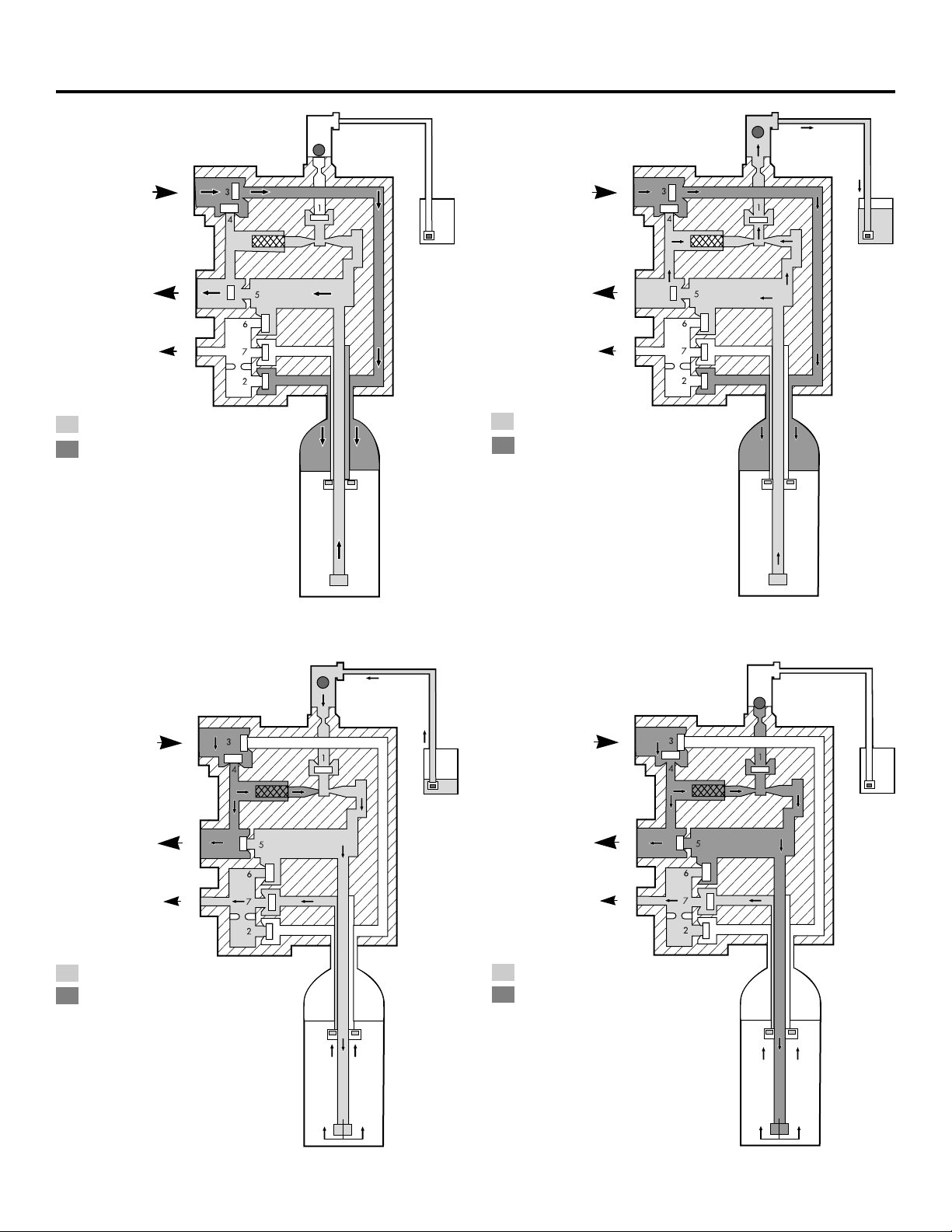
28
Flow diagrams.
1 Service Position
Inlet
Outlet
Drain
Treated Water
Untreated Water
Valve
No. Description Position
1 Brine Closed
2 Upper Drain Closed
3 Inlet Open
4 Bypass Closed
5 Outlet Open
6 Lower Drain Closed
7 Center Dist. Closed
2 Refill Position
Inlet
Outlet
Drain
Treated Water
Untreated Water
Valve
No. Description Position
1 Brine Open
2 Upper Drain Closed
3 Inlet Open
4 Bypass Closed
5 Outlet Open
6 Lower Drain Closed
7 Center Dist. Closed
3 Brine Draw Position
Inlet
Outlet
Drain
Treated Water
Untreated Water
Valve
No. Description Position
1 Brine Open
2 Upper Drain Closed
3 Inlet Closed
4 Bypass Open
5 Outlet Closed
6 Lower Drain Closed
7 Center Dist. Open
4 Slow Rinse Position
Inlet
Outlet
Drain
Treated Water
Untreated Water
Valve
No. Description Position
1 Brine Open
2 Upper Drain Closed
3 Inlet Closed
4 Bypass Open
5 Outlet Closed
6 Lower Drain Closed
7 Center Dist. Open
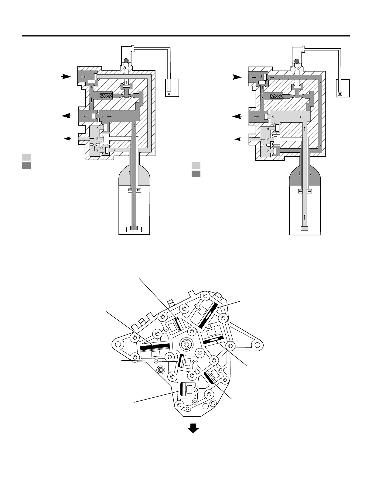
29
ge.com
5 Backwash Position
Inlet
Outlet
Drain
Treated Water
Untreated Water
Valve
No. Description Position
1 Brine Closed
2 Upper Drain Open
3 Inlet Closed
4 Bypass Open
5 Outlet Open
6 Lower Drain Closed
7 Center Dist. Closed
6 Fast Rinse Position
Inlet
Outlet
Drain
Treated Water
Untreated Water
Valve Disc Identification
Disc 6 – Lower Drain
Disc 3 – Inlet
Disc 2 – Upper Drain
Disc 7 – Center Distributor
Disc 5 – Outlet
Disc 4 – Bypass
Disc 1 – Brine
Valve
No. Description Position
1 Brine Closed
2 Upper Drain Closed
3 Inlet Open
4 Bypass Open
5 Outlet Closed
6 Lower Drain Open
7 Center Dist. Closed
1. Disconnect power to the control by unplugging the wall
transformer or unplugging the power cord from the bottom
of the control.
2. Press down on the top of the drive gear to disengage the
cam gear.
3. With the cam gear disengaged, rotate the cam gear
counterclockwise to the REFILL position until the air check
fills with water, and water flows through the brine line into
the brine tank. Do not run for more than three minutes.
4. Press down on the drive gear, and rotate the cam gear
counterclockwise to the DRAW/RINSE position. Check that
water is being drawn from the brine tank. The water level
in the brine tank will recede very slowly. Observe the water
level for at least one minute. If the water level does not
recede, if it goes up or if air enters the transparent air
check chamber and the ball falls and seats, refer to
the Troubleshooting section in this manual.
5. When water is being drawn from the brine tank,
press down on the drive gear and rotate the cam gear
counterclockwise to just before the SERVICE position.
Connect power to the control and allow the motor to drive
the cam gear to the SERVICE position. The motor will stop.
Run cold water from a nearby faucet until the water is
clear and soft.
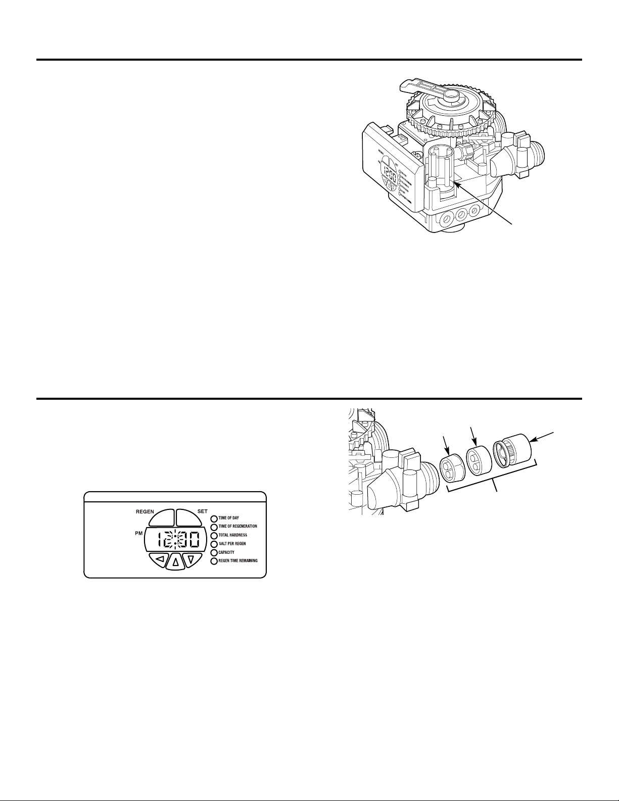
Checking the brine draw and refill function.
In rare instances, the turbine wheel of the water meter can
collect small particles of oxidized iron, eventually preventing
the wheel from turning.
If the flow indicator light does not blink when conditioned
water is flowing from the unit, it is an indication that the
turbine wheel is not turning.
1. Disconnect electrical power to the unit.
2. Shut off the water supply or put the bypass valve(s) into the
BYPASS position.
3. Relieve resin tank pressure:
A. Remove control valve cover.
B. Press down on the top of the drive gear to disengage the
cam gear.
C. With the cam gear disengaged, rotate the cam gear
counterclockwise to the BACKWASH position.
Check that there is no water flow through the drain line
before performing service or preventative maintenance.
4. Disconnect the water conditioner from the plumbing.
5. Using a needle-nose pliers, remove the outer gland and
the turbine wheel from the outlet of the valve. Generally,
it will not be necessary to remove the inner gland.
6. Clean all iron deposits and/or debris off the turbine wheel.
Excessive accumulation of iron may be removed from the
components with a solution of sodium hydrosulfite (or
sodium disulfite). Rinse the components thoroughly in
clean water after using the iron removal solution.
7. Flush accumulated iron deposits and/or debris from the
inside of the valve outlet.
8. Reinstall the turbine wheel into the outlet side of the valve,
being certain that the turbine wheel shaft is carefully
seated into the bearing of the inner gland.
9. Carefully reinstall the outer gland into the outlet side of
the valve. Check turbine rotation.
10. Reconnect the water conditioner to the plumbing and
follow Initial Start-Up section.
11. Open the downstream faucet (conditioned water) and
check to be certain that the flow indicator (colon) is
blinking.
Water meter.
30
Air
check
Outer
gland
Turbine
wheel
Inner
gland
Turbine assembly
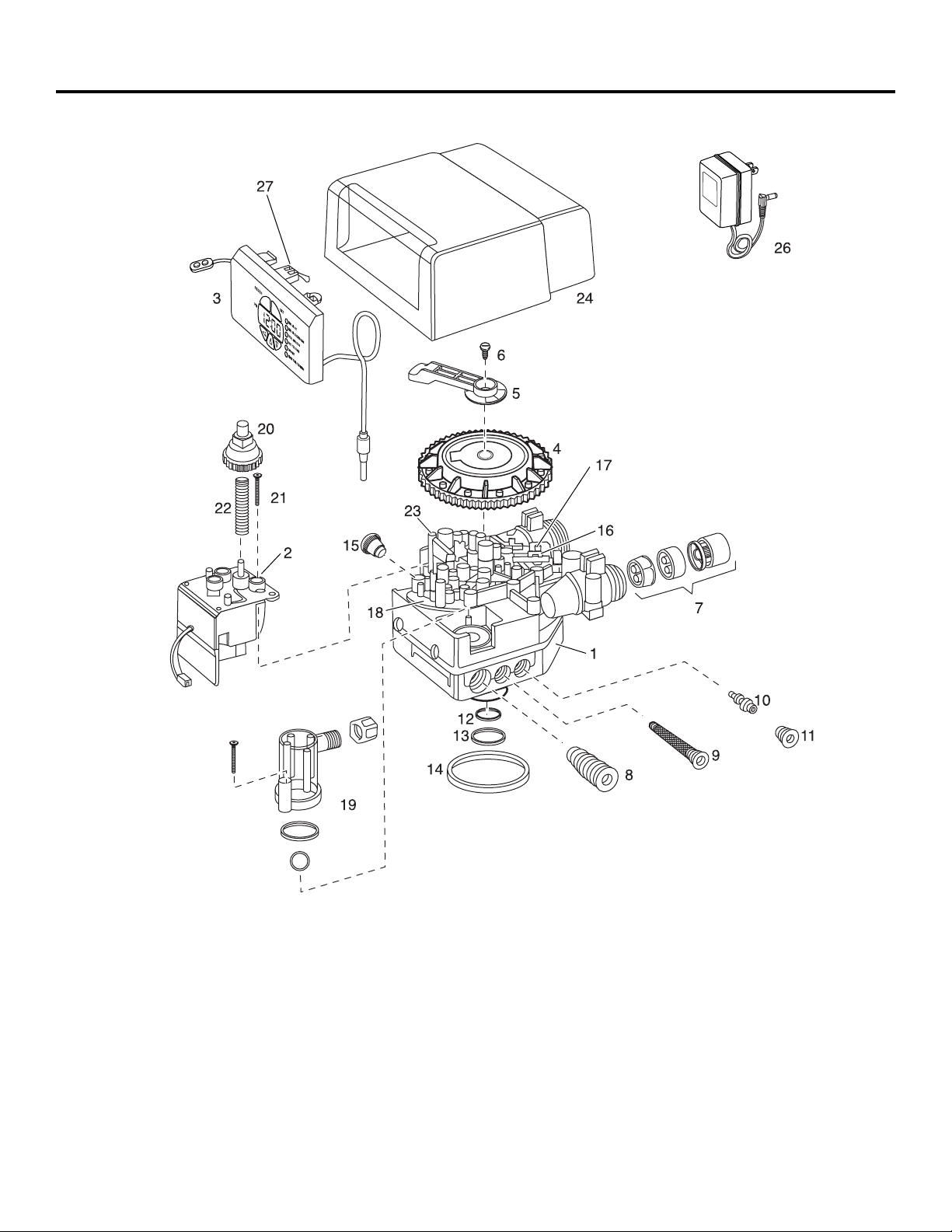
31
Control valve diagram. ge.com
32
Systems diagram.
42
34
33
35
32
36
41
40
37
39
38
44
47
43

33
Parts List. ge.com
GENERAL ELECTRIC PARTS CATALOG
GG
NN
PP
RR
44
08
LL
(00) (00)
REF. NO. GE PART NO. PART DESCRIPTION QTY QTY
0001 WS15X10054 VALVE BODY ASSEMBLY 1 1
0002 WS26X10014 DRIVE MOTOR – 60 Hz 1 1
0003 WS21X10022 CONTROL ASSEMBLY 1 1
0004 WS26X10015 CAM GEAR 1 1
0005 WS28X10050 BRACKET 1 1
0006 WS02X10037 SCREW, 10-32 X 1/2 1 1
0007 WS26X10016 TURBINE GROUP 1 1
0008 WS15X10055 BRINE/BACKWASH CONTROL 1 1
0009 WS15X10056 INJECTOR SCREEN ASSEMBLY 1 1
0010 WS15X10059 INJECTOR ASSEMBLY, 4 BUMPS 1 1
0010 WS15X10060 INJECTOR ASSEMBLY, 5 BUMPS 1 1
0011 WS31X10032 INJECTOR CAP ASSEMBLY 1 1
0012 WS03X10049 O-RING, 1 X 1-1/4 X 1/8 1 1
0013 WS03X10050 O-RING, 1-5/16 X 1/2 X 3/32 1 1
0014 WS03X10051 O-RING, 3-1/8 ID X 3/16 1 1
0015 WS31X10033 CAP PLUG 1 1
0016 WS35X10053 VALVE DISC KIT 1 1
0017 WS03X10052 VALVE DISC SPRING 1 1
0018 WS31X10034 TOP PLATE WITH SPRINGS 1 1
0019 WS35X10054 AIR CHECK KIT 1 1
0020 WS26X10017 DRIVE GEAR 1 1
0021 WS02X10038 SCREW, 8-18 X 1-1/2 1 1
0022 WS03X10053 SPRING 1 1
0023 WS02X10039 TOP PLATE SCREW 1 1
0024 WS31X10035 BLACK COVER 1 1
0026 WS26X10018 TRANSFORMER – 120V 1 1
0027 WS21X10023 MICRO SWITCH 1 1
0032 WS32X10024 10 X 44 RESIN TANK 1
WS32X10027 12 X 48 RESIN TANK 1
0033 WS14X10003 DISTRIBUTOR, 10 X 44 TANK 1
WS14X10004 DISTRIBUTOR, 12 X 48 TANK 1
0034 WS01X10016 RESIN MEDIA, 1.5 CUFT 1 1
0035 WS31X10036 RESIN TANK COVER 1
0036 WS07X10022 BRINE LINE – 5 FT 1 1
0037 WS32X10025 BRINE TANK 1 1
0038 WS32X10026 BRINE WELL 1 1
0039 WS35X10055 FLOAT ASSEMBLY 1 1
0040 WS02X10040 OVERFLOW FITTING 1 1
0041 WS31X10037 BRINE WELL CAP 1 1
0042 WS60X10015 1″ COPPER TAIL PIECE 1 1
0043 WS15X10057 BYPASS VALVE 1 1
0044 WS31X10038 BRINE TANK LID 1 1
0047 WS16X10001 BYPASS VALVE GASKETS 1 1
34
What Is Not Covered:
For The Period Of: We Will Replace:
One Year Any part of the Water Softening System which fails due to a defect in materials or workmanship.
From the date of the During this limited one-year warranty, GE will also provide, free of charge, all labor and related
original purchase service to replace the defective part.
Three Years The electronic monitor, if it fails due to a defect in materials or workmanship. During this
From the date of the three-year limited warranty, you will be responsible for any labor or related service costs.
original purchase
Ten Years A replacement brine tank or cabinet, if either fails due to a defect in materials or workmanship.
From the date of the During this ten-year limited warranty, you will be responsible for any labor or related service costs.
original purchase
■ Service trips to your home to teach you how to use
the product.
■ Improper installation, delivery or maintenance.
■ Failure of the product if it is abused, misused, altered, used
commercially or used for other than the intended purpose.
■ Use of this product where water is microbiologically unsafe
or of unknown quality, without adequate disinfection before
or after the system. Systems certified for cyst reduction may
be used on disinfected water that may contain filterable
cysts.
■ Replacement of house fuses or resetting of circuit breakers.
■ Damage to the product caused by accident, fire, floods or
acts of God.
■ Incidental or consequential damage caused by possible
defects with this appliance, its installation or repair.
■ Product not accessible to provide required service.
This warranty is extended to the original purchaser and any succeeding owner for products purchased for home use within
the USA. If the product is located in an area where service by a GE Authorized Servicer is not available, you may be
responsible for a trip charge or you may be required to bring the product to an Authorized GE Service location for service.
In Alaska, the warranty excludes the cost of shipping or service calls to your home.
Some states do not allow the exclusion or limitation of incidental or consequential damages. This warranty gives you
specific legal rights, and you may also have other rights which vary from state to state. To know what your legal
rights are, consult your local or state consumer affairs office or your state’s Attorney General.
Warrantor: General Electric Company. Louisville, KY 40225
GE Water Softening System Warranty. (For Customers in the United States)
All warranty service provided by our SmartWater
™
Authorized Servicer
Network. To schedule service, call 800.952.5039 (U.S.) or 866.777.7627
(Canada). Please have serial number and model number available when
calling for service.
Staple your receipt here.
Proof of the original purchase
date is needed to obtain service
under the warranty.
EXCLUSION OF IMPLIED WARRANTIES—Your sole and exclusive remedy is product repair as provided in this
Limited Warranty. Any implied warranties, including the implied warranties of merchantability or fitness for
a particular purpose, are limited to one year or the shortest period allowed by law.
WARRANTOR IS NOT RESPONSIBLE FOR CONSEQUENTIAL DAMAGES.
Warrantor: MABE CANADA INC.
All warranty service provided by our Factory Service Centers or an authorized technician. For service,
call toll free 1.866.777.7627. Please have serial number and model number available when calling for service.
GE Water Softening System Warranty. (For Customers in Canada)
What Is Not Covered:
For The Period Of: We Will Replace:
One Year Any part of the Water Softening System which fails due to a defect in materials or workmanship.
From the date of the During this limited one-year warranty, GE will also provide, free of charge, all labor and related
original purchase service to replace the defective part.
Three Years The electronic monitor, if it fails due to a defect in materials or workmanship. During this
From the date of the three-year limited warranty, you will be responsible for any labor or related service costs.
original purchase
Ten Years A replacement brine tank or cabinet, if either fails due to a defect in materials or workmanship.
From the date of the During this ten-year limited warranty, you will be responsible for any labor or related service costs.
original purchase
■ Service trips to your home to teach you how to use
the product.
■ Improper installation, delivery or maintenance.
■ Failure of the product if it is abused, misused, altered, used
commercially or used for other than the intended purpose.
■ Use of this product where water is microbiologically unsafe
or of unknown quality, without adequate disinfection before
or after the system. Systems certified for cyst reduction may
be used on disinfected water that may contain filterable
cysts.
■ Replacement of house fuses or resetting of circuit breakers.
■ Damage to the product caused by accident, fire, floods or
acts of God.
■ Incidental or consequential damage caused by possible
defects with this appliance, its installation or repair.
■ Product not accessible to provide required service.
This warranty is extended to the original purchaser and any succeeding owner for products purchased for home use within
Canada. In-home warranty service will be provided in areas where it is available and deemed reasonable by Mabe to provide.
EXCLUSION OF IMPLIED WARRANTIES—Your sole and exclusive remedy is product repair as provided in this
Limited Warranty. Any implied warranties, including the implied warranties of merchantability or fitness for
a particular purpose, are limited to one year or the shortest period allowed by law.
35
Consumer Support.
Printed in the United States
GE Appliances Website ge.com
Have a question or need assistance with your appliance? Try the GE Appliances Website 24 hours a day,
any day of the year! For greater convenience and faster service, you can now download Owner’s Manuals
or order parts online.
Schedule Service ge.com
Expert GE repair service is only one step away from your door. Schedule your service at your convenience by
calling 800.GE.CARES (800.432.2737) during normal business hours.
Real Life Design Studio ge.com
GE supports the Universal Design concept—products, services and environments that can be used by
people of all ages, sizes and capabilities. We recognize the need to design for a wide range of physical and
mental abilities and impairments. For details of GE’s Universal Design applications, including kitchen design ideas
for people with disabilities, check out our Website today. For the hearing impaired, please call 800.TDD.GEAC
(800.833.4322).
Extended Warranties ge.com
Purchase a GE extended warranty and learn about special discounts that are available while your warranty
is still in effect. You can purchase it on-line anytime, or call 800.626.2224 during normal business hours.
GE Consumer Home Services will still be there after your warranty expires.
Parts and Accessories ge.com
Individuals qualified to service their own appliances can have parts or accessories sent directly to their homes
(VISA, MasterCard and Discover cards are accepted). Order on-line today, 24 hours every day or
by phone at 800.626.2002 during normal business hours.
Instructions contained in this manual cover procedures to be performed by any user. Other servicing
generally should be referred to qualified service personnel. Caution must be exercised, since improper
servicing may cause unsafe operation.
Contact Us ge.com
If you are not satisfied with the service you receive from GE, contact us on our Website with all the details
including your phone number, or write to: General Manager, Customer Relations
GE Appliances, Appliance Park
Louisville, KY 40225
Register Your Appliance ge.com
Register your new appliance on-line—at your convenience! Timely product registration will allow for
enhanced communication and prompt service under the terms of your warranty, should the need arise.
You may also mail in the pre-printed registration card included in the packing material, or detach and
use the form in this Owner’s Manual.