
Water Softening
system
Safety Information . . . . . . . . . . . . .2
Installation Instructions . . .3–12
Step-by-step instructions . . . . . . .6–12
Operating Instructions
Breaking a salt bridge . . . . . . . . . . . . .14
Cleaning the nozzle and
venturi assembly . . . . . . . . . . . . . . . . .14
Features . . . . . . . . . . . . . . . . . . . . . .15, 16
Service . . . . . . . . . . . . . . . . . . . .13, 16–20
Water softener system . . . . . . . .13–21
Care and Cleaning . . . . . . . . . . . .22
Troubleshooting Tips . . . . . .23–25
Consumer Support
Consumer Support . . . . . . .Back Cover
Parts list/catalog . . . . . . . . . . . . . .27–30
Warranty . . . . . . . . . . . . . . . . . . . . . . . .31
ge.com
7289362 215C1173P024 49-50179 07-06 JR
Write the model and serial
numbers here:
Model # ________________
Serial # ________________
You can find them on the
back of the control head.
Model GNSM48F
Owner’s Manual &
Installation Instructions
Water Softening
System
System tested and certified by NSF International against NSF/ANSI Standard 44 for the
chemical reduction claims specified on the performance data sheet.
IMPORTANT SAFETY INFORMATION.
READ ALL INSTRUCTIONS BEFORE USING.
SAFETY PRECAUTIONS
■ Check and comply with your state and local codes.
You must follow these guidelines.
■ Use care when handling the water softening
system. Do not turn upside down, drop, drag
or set on sharp protrusions.
■ Water softening systems using sodium chloride
(salt) for recharge add sodium to the water.
Persons on sodium restricted diets should consider
the added sodium as part of their overall intake.
Potassium chloride can be used as an alternative
to sodium chloride in your softener.
■
The water softening system works on 24 volt-60 Hz
electrical power only. Be sure to use only the
included transformer.
■ Transformer must be plugged into an indoor
120 volt, grounded outlet only.
■ Use clean water softening salts only, at least 99.5%
pure. NUGGET, PELLET or coarse SOLAR salts are
recommended. Do not use rock, block, granulated
or ice cream making salts. They contain dirt and
sediments, or mush and cake, and will create
maintenance problems.
■ Keep the salt hole cover in place on the softener
unless servicing the unit or refilling with salt.
WARNING: Do not use with water that
is microbiologically unsafe or of unknown quality
without adequate disinfection before or after the
system.
READ AND FOLLOW THIS SAFETY INFORMATION CAREFULLY.
SAVE THESE INSTRUCTIONS
PROPER INSTALLATION
■ Install or store where it will not be exposed to
temperatures below freezing or exposed to any
type of weather. Water freezing in the system will
break it. Do not attempt to treat water over 100°F.
■ Do not install in direct sunlight. Excessive sun or
heat may cause distortion or other damage to
non-metallic parts.
■ Properly ground to conform with all governing
codes and ordinances.
■ Use only lead-free solder and flux for all
sweat-solder connections, as required by
state and federal codes.
■
The water softening system requires a minimum
water flow of three gallons per minute at the inlet.
Maximum allowable inlet water pressure is 125 psi.
If daytime pressure is over 80 psi, nighttime pressure
may exceed the maximum. Use a pressure reducing
valve to reduce the flow if necessary.
■
Softener resins may degrade in the presence of
chlorine above 2 ppm. If you have chlorine in excess
of this amount, you may experience reduced life
of the resin. In these conditions, you may wish to
consider purchasing a GE point-of-entry household
filtration system with a chlorine reducing filter.
WARNING: Discard all unused parts
and packaging material after installation. Small
parts remaining after the installation could be
a choke hazard.
This water softening system must be properly installed and located in accordance with the
Installation Instructions before it is used.
2
For your safety, the information in this manual must be followed to minimize the risk of electric
shock, property damage or personal injury.
WARNING!
3
Installation Water Softening System
Instructions
Model GNSM48F
Questions? Call 800.GE.CARES (800.432.2737) or Visit our Website at: ge.com
BEFORE BEGINNING INSTALLATION
Read these instructions completely and carefully.
•
IMPORTANT — Save these instructions
for local inspector’s use.
•
IMPORTANT — Observe all governing
codes and ordinances.
• Note to Installer – Be sure to leave these
instructions with the Consumer.
• Note to Consumer – Keep these instructions
for future reference.
• Proper installation is the responsibility of the
installer.
• Product failure due to improper installation
is not covered under the Warranty.
• A shutoff valve must be available or added near
the installation point.
WARNING:
Read entire manual. Failure to follow all guides and rules could cause personal
injury or property damage.
• Check with your state and/or local public works department for plumbing codes. You must follow their
guides as you install the Water Softening system.
NOTE: Failure to comply with these installation instructions will void the product warranty, and the
installer will be responsible for any service, repair or damages caused thereby.
IMPORTANT INSTALLATION
RECOMMENDATIONS
(CONT.)
• Use care when handling the softener. Do not
turn upside down, drop, drag or set on sharp
protrusions.
• Maximum allowable inlet water pressure is 125
psi. If daytime pressure is over 80 psi, nighttime
pressure may exceed the maximum. Use a
pressure reducing valve if necessary. (Adding a
pressure reducing valve may reduce the flow.)
• The softener works on 24 volt-60 Hz electrical
power only. Be sure to use the included
transformer. Be sure the electric outlet and
transformer are in an inside location to protect
from moisture.
• See Where to Install the Softener section
for more details.
WARNING: Do not use with water
that is microbiologically unsafe or of unknown
quality without adequate disinfection before or
after the system. The water should be tested
periodically to verify that the system is
performing satisfactorily.
• Small parts remaining after the installation could
be a choke hazard. Discard safely.
IMPORTANT INSTALLATION
RECOMMENDATIONS
• In the Commonwealth of Massachusetts,
Plumbing Code 248 CMR shall be adhered to.
Consult with your licensed plumber.
• Use only lead-free solder and flux for all sweat-
solder connections, as required by state and
federal codes.
• Connect the softener to the main water supply
pipe before or ahead of the water heater.
DO NOT RUN HOT WATER THROUGH THE
SOFTENER. Temperature of water passing
through the softener must be less than 120°F.

Installation Instructions
4
UNPACKING AND INSPECTION
Be sure to check the entire softener for any
shipping damage or parts loss. Also note damage
to the shipping cartons. Contact the transportation
company for all damage and loss claims. The
manufacturer is not responsible for damages
in transit.
Small parts needed to install the softener are
packaged either in a bag or on a cardboard
sheet. To avoid loss of the small parts, keep them
packaged until you are ready to use them. Be sure
not to discard components hidden in packaging.
TOOLS AND MATERIALS REQUIRED
FOR INSTALLATION
• Pliers
• Screwdriver
• Teflon tape
• Razor knife
• Two adjustable wrenches
• Additional tools may be required if modification
to home plumbing is necessary.
• In and out fittings included with the softener are
1″ NPT male adapters. You should maintain the
same, or larger, pipe size as the water supply
pipe, up to the softener inlet and outlet. Then,
use the necessary adapters to connect the water
supply to the 1″ NPT male adapters.
• Use the included bypass valve to install the
softener. The bypass valve allows you to turn off
water to the softener for servicing, but still have
water in the house pipes. The in and out fittings
referred to above connect to the bypass valve
with the included bypass clips.
• Use appropriate fitting/pipe material (i.e., copper,
brass, galvanized or CPVC) to connect the 1″ NTP
plastic adapters to the house plumbing.
• If additional drain hose is needed for valve and
salt tank drains, it can be ordered from GE Parts
at 800.626.2002, part number WS07X10004.
• If a rigid valve drain is needed to comply with
plumbing codes, you can buy the parts needed
to connect a 1/2″ copper tubing or plastic pipe
drain. See Step 5.
• Clean nugget or pellet water softener salt is
needed to fill the brine tank. See Step 11.
WHERE TO INSTALL THE SOFTENER
• Place the softener as close as possible to a
sewer drain, or other acceptable drain point
or standpipe.
• It is recommended to keep outside faucets
on hard water to save soft water and salt.
• Do not install the softener in a place where it
could freeze. Freeze damage is not covered by
the warranty.
• Do not install the softener where it would block
access to the water heater or access to the main
water shutoff.
• Put the softener in a place where water damage
is least likely to occur if a leak develops. The
manufacturer will not repair or pay for water
damage.
• A 120-volt electric outlet is needed to plug in the
included transformer. The softener has a 10-foot
power cable. If the outlet is remote (up to 100
feet), use 18 gauge wire to connect. Be sure the
electric outlet and transformer are in an inside
location, to protect from wet weather. Be sure
the outlet is unswitched to prevent accidental
shutoff.
• If installing in an outside location, you must
take the steps necessary to assure the softener,
installation plumbing, wiring, etc., are as well
protected from the elements (sunlight, rain, wind,
heat, cold), contamination, vandalism, etc., as
when installed indoors. Outdoor installation is
not recommended, and voids the warranty.
• Keep the softener out of direct sunlight.
The sun’s heat may distort non-metallic
parts and may damage the electronics.
Installation Instructions
PLAN HOW YOU WILL INSTALL THE
SOFTENER
You must first decide how to run in and out pipes
to the softener. Look at the house main water pipe
at the point where you will connect the softener.
Is the pipe soldered copper, glued plastic or
threaded galvanized? What is the pipe size?
WARNING: Use only lead-free solder and
flux to prevent lead poisoning.
See Typical Installation Illustration. Use this as a guide
when planning your particular installation. Be sure
to direct the incoming hard water supply to the
softener valve inlet fitting. The valve is marked
IN and OUT.
5
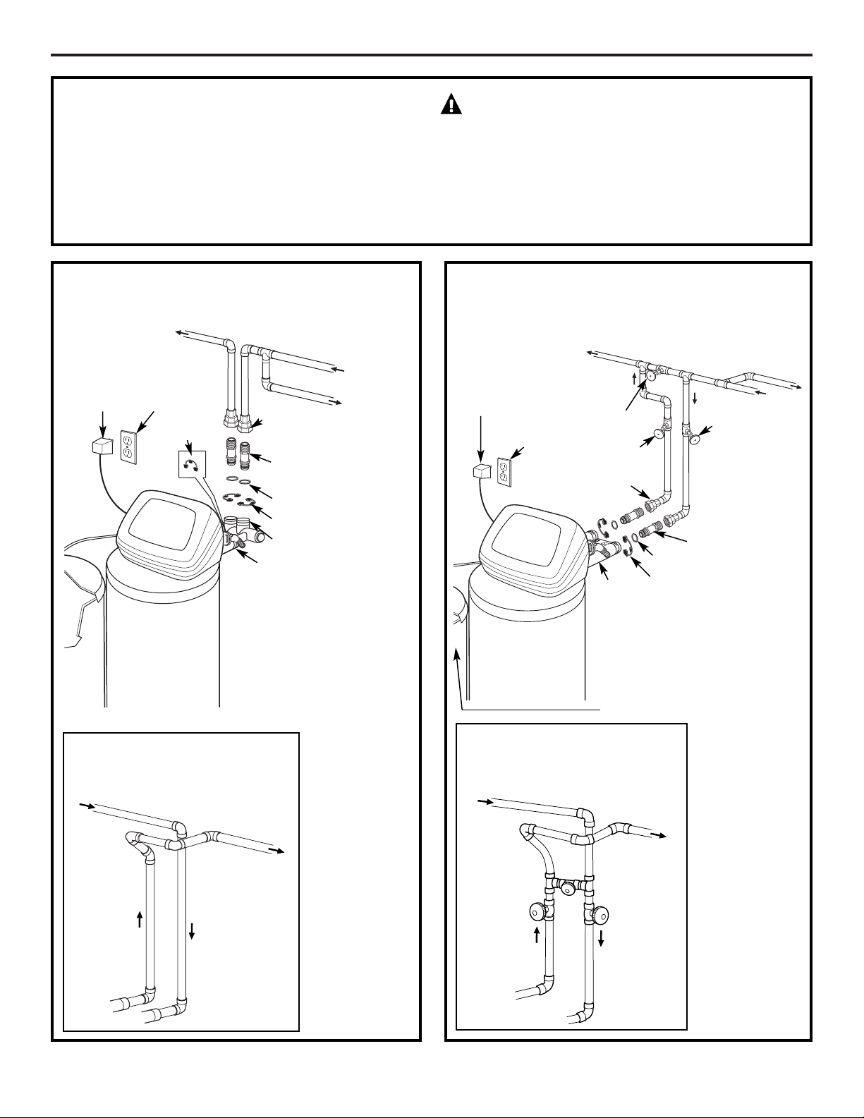
TYPICAL INSTALLATION ILLUSTRATION
Soft water
MAIN WATER PIPE
Hard
water
NOTE: See Drain
Hose Connections
section.
24V
transformer
120-volt
outlet
O-rings (2)
1″ NPT male
adapter (2)
Clips (2)
1″ female
adapter (2)
(not supplied)
Clips
O-rings (2)
Brine
tank
INLET
Hard
water to
outside
faucets
Fig. 1
CROSSOVER
Use if water supply flows
from the left. Include single
or 3-valve bypass.
Hard
water
From
softener
outlet
Soft
water
To softener
inlet
OPTIONAL 3-VALVE BYPASS
INSTALLATION ILLUSTRATION
Bypass
valve
Hard water
to outside
faucets
Inlet
valve
Outlet valve
O-rings (2)
1″ NPT male
adapter (2)
Clips (2)
INLET
MAIN WATER PIPE
Hard
water
Soft water
120-volt
outlet
24V
transformer
1″ female adapter
(2) (not supplied)
Fig. 2
CROSSOVER
Use if water supply flows
from the left. Include single
or 3-valve bypass.
Hard
water
From
softener
outlet
Soft
water
To softener
inlet
Brine tank
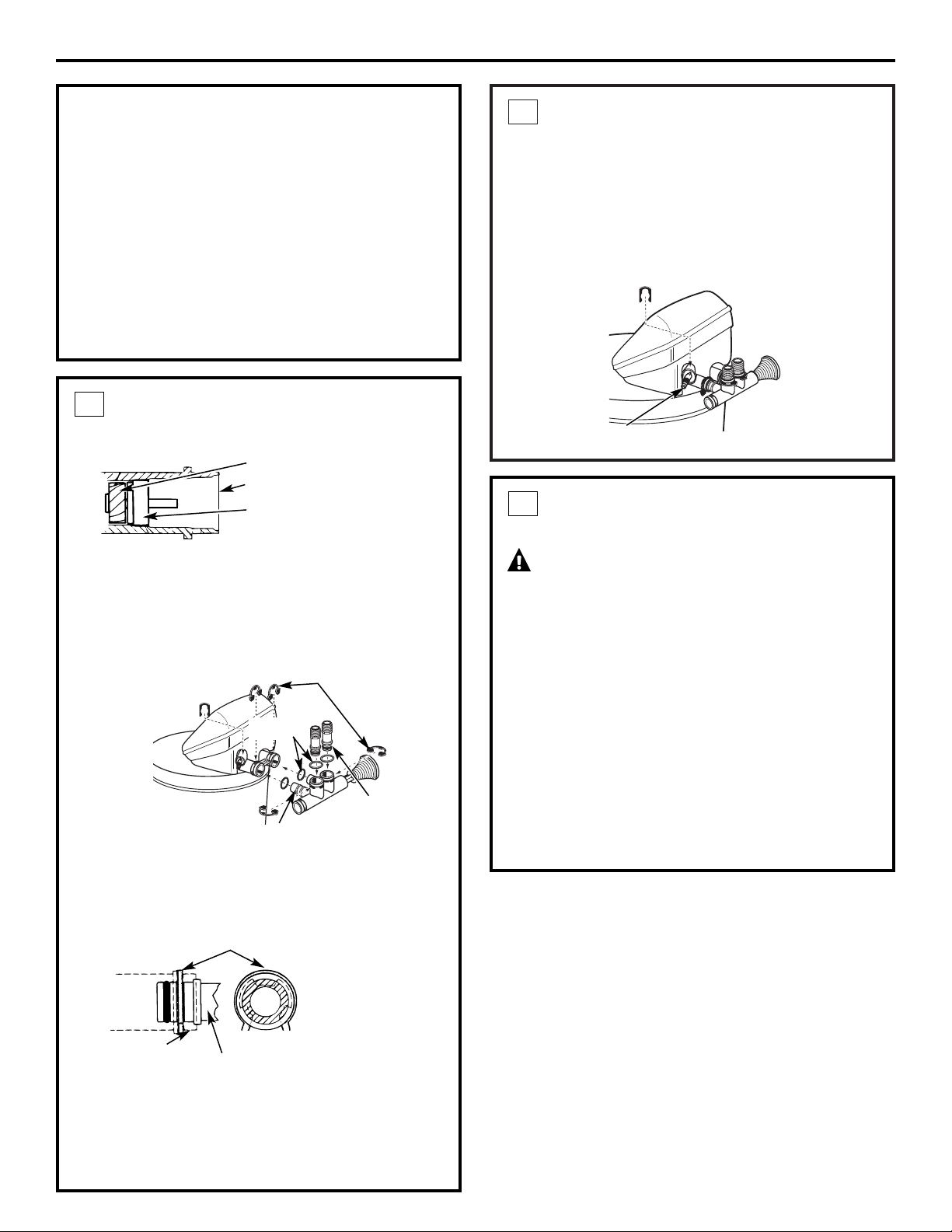
INSTALL DRAIN FITTING
• Push the drain fitting (lubricate o-ring seals
with silicone grease) into the part of the valve
as shown.
• Snap the large plastic clip in place, from the
top down as shown. Be sure the clip snaps into
place. Pull on the drain fitting to make sure it is
held securely in place.
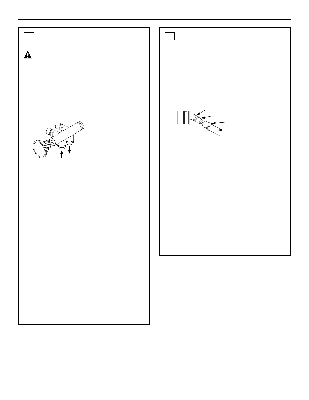
2
INSTALL BYPASS VALVE
• Remove plastic shipping plug and wire from valve
outlet.
• Push the bypass valve (lubricate o-ring seals with
silicone grease) into both ports of the valve as
shown.
• Snap the 2 large plastic clips in place, from the
top down, as shown.
• Push the NPT adapters (lubricate o-ring seals with
silicone grease) into both ports of the valve as
shown.
• Snap the 2 large plastic clips in place, from the
side, as shown.
1
Valve body
inlet or outlet
Bypass valve
(push all the way in)
Clip
END
VIEW
SIDE
VIEW
Installation Instructions
6
BEFORE YOU BEGIN
• Turn off the gas or electric supply to the water
heater, in the possibility that the water heater
may be drained while draining pipes.
• Turn off the water supply to pipes to be cut and
drain the house water pipes.
• Open both hot and cold faucets at the lowest
location possible.
NOTE: For easier installation, remove the top cover.
Release 2 clips at rear of cover. Rotate cover
forward and lift up.
Turbine
Valve outlet
Turbine shaft and
support
NOTE: Be sure the turbine and support are firmly
in place in the valve outlet. Blow into the valve port
and observe the turbine for free rotation.
Clips
O-rings
O-ring seal goes into the outer
groove only. The clip snaps into
the inner groove (see below).
NPT adapter
Drain fitting
MOVE THE SOFTENER ASSEMBLY
INTO INSTALLATION POSITION
CAUTION:
• Secure the resin tank to a stable structure to
prevent it from falling over.
• Locate the brine tank directly next to the resin
tank.
• Be sure the installation surface is level and
smooth. Sharp objects under the brine tank may
puncture it. If needed, place the brine tank on a
section of 3/4″ thick (minimum) plywood. Then,
place shims under the plywood as needed to
level the softener.
• Connect the black brine valve tube from the
brinewell to the venturi assembly on the valve,
using the plastic nut provided.
3
PLUMB “IN” AND “OUT” PIPES
TO AND FROM SOFTENER
CAUTION: Observe all of the following
cautions as you connect inlet and outlet
plumbing. See Typical Installation Illustration.
• BE SURE INCOMING HARD WATER SUPPLY IS
DIRECTED TO THE SOFTENER VALVE INLET PORT.
If house water flow is from the left, use a
plumbing crossover as shown in Typical
Installation Illustration. If house water flows up
from the floor level, turn the bypass valve upside
down as shown.
• With the softener in place, determine the correct
length of piping required to connect the household
plumbing to the NPT male adapter.
• Remove softener from installation space.
• If making a soldered copper installation, do all
sweat soldering before connecting pipes to the
NPT adapters and bypass valve. Torch heat will
damage plastic parts.
• When turning threaded pipe fittings onto plastic
fittings, use care not to cross-thread.
• Use Teflon Tape on all external pipe threads.
• Support inlet and outlet plumbing in some manner
(use pipe hangers) to keep the weight off of the
valve fittings.
• Slide softener back into position.
• Make final connections to the bypass valve and
snap clips into place.
Be sure the clips for the bypass valve and NPT
adapters snap into place. Pull on the bypass valve
and NPT adapters to make sure the parts are held
securely in place.
4
Installation Instructions
7
IN
OUT
Turn bypass
valve upside
down to
connect to
floor level
plumbing
CONNECT AND RUN THE VALVE
DRAIN HOSE
IMPORTANT: If you want to attach the drain fitting
to a rigid tube, see Connecting a Rigid Valve Drain
Tube section on next page.
• Use the provided drain hose (20′ length included)
to attach to the valve drain fitting. To keep water
pressure from blowing the hose off, use supplied
spring clamp to secure in place. Cut the necessary
length and use the remainder in Step 8.
• Locate the other end of the hose at a suitable
drain point (floor drain, sump, laundry tub, etc.)
that terminates at the sewer. Check and comply
with local codes.
IMPORTANT: If more drain hose is needed, it
should be ordered from GE Parts at 800.626.2002,
part number WS07X10004. The water softener will
not work if water cannot exit this hose during
recharge.
• Tie or wire the hose in place at the drain point.
High water pressure will cause it to whip during
the back-wash and fast rinse cycles of recharge.
Also provide an air gap of at least 1-1/2″
between the end of the hose and the drain
point. An air gap prevents possible siphoning of
sewer water into the softener, if the sewer should
“back-up.”
5
Barbs for 3/8
″
I.D. tubing
Hose clamp
1/4
″
NPT thread
Drain hose
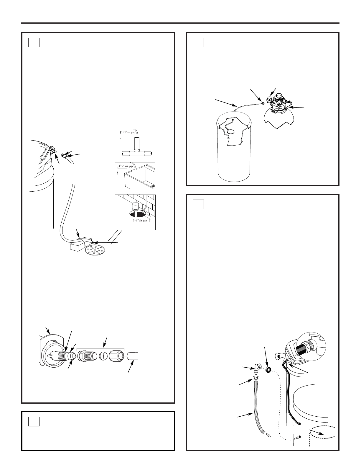
INSTALL THE BRINE TANK
OVERFLOW FITTINGS AND HOSE
• Insert the rubber grommet into the 3/4″ diameter
hole in the brine tank sidewall as shown.
• Push the end of the hose adapter elbow into the
grommet as shown.
• Attach a length of hose (use remaining hose from
Step 5) to the hose adapter elbow. Use a hose
clamp to hold it in place.
• Locate the other end of the hose at the drain
point. DO NOT ELEVATE this hose higher than the
elbow on the brine tank.
IMPORTANT: DO NOT TEE OVERFLOW HOSE
TO VALVE DRAIN HOSE.
NOTE: This drain is for safety only. If the cabinet
(brine tank) should
over-fill with water,
the excess is carried
to the drain.
8
BRINE TUBING CONNECTION
• Route the brine tubing out of the largest hole in
the brine tank sidewall. Use the compression nut
(in parts bag) to connect tubing to the nozzle
assembly at the main valve.
7
Installation Instructions
CONNECT AND RUN THE VALVE
DRAIN HOSE
(CONT.)
• Elevating the drain hose may cause back
pressure that could reduce the brine draw during
recharge. If raising the drain line overhead is
required to get to the drain point, measure the
inlet water pressure to the softener first. For inlet
pressures between 20 and 50 psi, do not raise
higher than 8′ above the floor. For inlet pressure
above 50 psi, the drain line may be raised to a
maximum height of 14′.
CONNECTING A RIGID VALVE DRAIN TUBE
To adapt a copper drain tube to the softener, buy a
compression fitting (1/4 NPT x 1/2″ O.D. tube) and
needed tubing from your local hardware store.
5
Clip
1/4″ NPT
thread
1/2″ outside
diameter copper
tube (not provided)
Compression fitting
1/4 NPT x 1/2″ O.D.
tube (not provided)
Cut barbs from valve
drain elbow (pull clip
and remove drain valve
elbow from valve)
Barbs
Brine tubing
Compression nut
Nozzle assembly
Valve
assembly
Brine tank
Fig. 4A
Drain
fitting
on valve
Valve
drain
hose
FLOOR DRAIN
Tie or
wire hose
in place
STANDPIPE
LAUNDRY TUB
SUMP
Clamp
1
1
⁄2″ air gap
INSTALL TIMER AND COVERS AND
MAKE HARNESS CONNECTION
See separate instructions included in box with parts.
6
To sewer drain
Hose
clamp
Hose
adapter
Grommet
Overflow
drain hose
Brine
tank
Venturi
nozzle
Brinewell
8
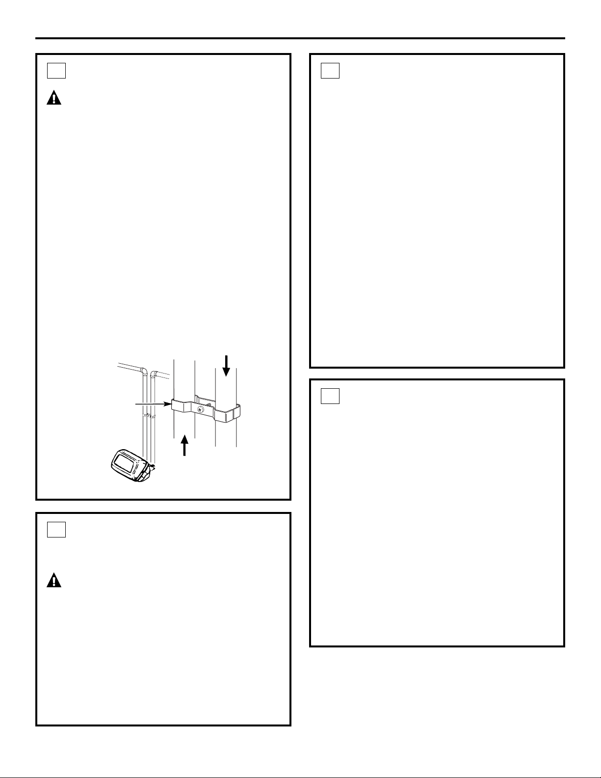
INSTALL GROUNDING CLAMP
DANGER: Failure to properly attach
ground clamp could result in electrical shock.
If plumbing is metal, to maintain electrical ground
continuity in the house cold water piping, install the
included ground clamp as shown.
• Clean pipe with emery paper in the area where
the clamp is to be installed.
• Install grounding clamps as shown, making sure
clamps fit freely around pipe.
• Make sure lock washer is in place.
• Handtighten screw, then one more full turn with
screwdriver.
NOTE: When replacing an existing softener, also
replace grounding clamps. If removing softener
completely, hard-plumb the water line with same
type of pipes as the original to assure plumbing
integrity and ground continuity over the life of
the home.
9
Ground
Clamp
From valve
outlet
To valve inlet
Installation Instructions
9
FLUSH PIPES, EXPEL AIR FROM
SOFTENER AND TEST YOUR
INSTALLATION FOR WATER
LEAKS
(CONT.)
• Place bypass valve in the “service” position
EXACTLY as follows. KEEP SOFT WATER FAUCETS
OPEN.
SLOWLY pull or slide the valve stem (out) toward
the service position, pausing several times to
allow the softener to pressurize slowly.
• After about 3 minutes, open a HOT water faucet
for 1 minute, or until all air is expelled, then
close. NOTE: If water appears cloudy or has salty
taste, allow to run for several more minutes, or
until clear.
• Close all water faucets.
• Check your plumbing work for leaks and fix
right away if any are found. Be sure to observe
previous caution notes.
• Turn on the gas or electric supply to the water
heater. Light the pilot, if applicable.
10
ADD WATER AND SALT TO THE
BRINE TANK
• Lift the salt hole cover. Add about 3 gallons of
water into the tank. Do not add into the brinewell.
• Fill tank with NUGGET, PELLET or coarse SOLAR
water softener salt with a purity of 99.5% or
higher. Do not use rock, block, granulated and ice
cream-making salts, or salt with iron-removing
additives (except for Diamond Crystal
®
Red•Out
®
brand salt). Maximum salt storage capacity is
approximately 200 lbs. Keep the salt hole cover
closed unless servicing the unit or refilling
with salt.
NOTE: If the softener is installed in a humid
basement or other damp area, it is better to fill the
tank with less salt, more frequently. Eighty to 100
lbs. of salt will last for several months, depending on
water hardness, family size and water softening
system model.
11
FLUSH PIPES, EXPEL AIR FROM
SOFTENER AND TEST YOUR
INSTALLATION FOR WATER LEAKS
CAUTION: To avoid water or air
pressure damage to softener inner parts, be
sure to do the following steps in exact order.
• Fully open 2 cold soft water faucets nearby
the softener.
• Place bypass valve in “bypass” position by
pushing the stem inward.
• Fully open the house main water pipe shutoff
valve. Observe a steady flow from both faucets
opened above.
10
Installation Instructions
10
CONNECT TO ELECTRICAL POWER
To gain access to the transformer/power cord
assembly, remove the salt hole cover from the
softener. Unclip the tabs on the rear of the top cover
and rotate the cover upward to remove. DO NOT
PULL OR DISCONNECT WIRING.
• The softener works on 24 volt-60Hz electric
power. The included transformer changes
standard 120-volt AC house power to 24 volts.
Plug the transformer into a 120-volt outlet only.
Be sure the outlet is always live so it can not be
switched off by mistake.
• Replace the top cover.
• Replace the salt hole cover.
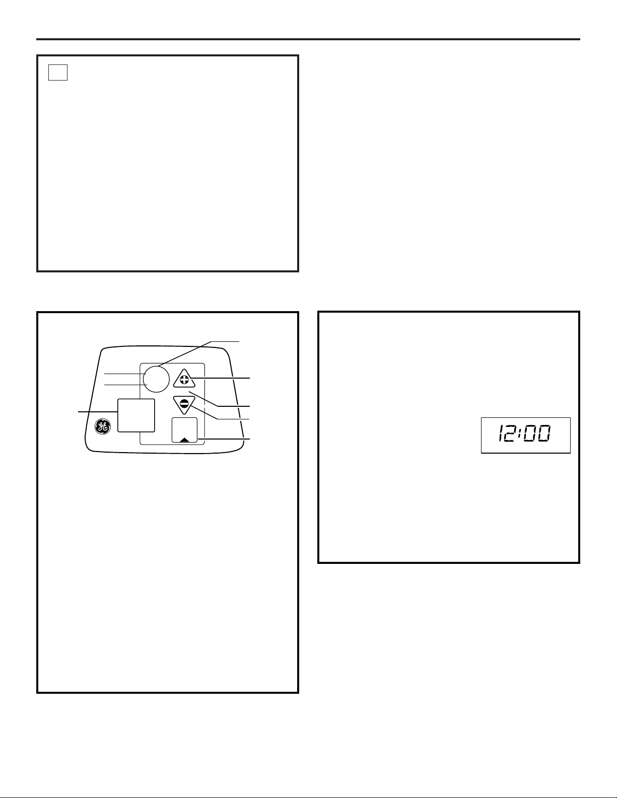
12
PROGRAMMING THE CONTROL
PROGRAMMING THE CONTROL
TIMER SETTINGS REQUIRED upon installation and
after an extended power outage.
NOTES:
• When the transformer is plugged into the
electrical outlet, 12:00 AM is flashing and the
words PRESENT TIME show in the upper display
area. Program the timer as instructed below.
If, A--- is flashing, see the Setting Model Code
section.
• A beep sounds while pressing buttons for timer
programming. One beep signals a change in the
timer display. Repeated beeps means the timer
will not accept a change from the button or arrow
you have pressed and you should use another.
• To program the timer, you will use the SET, UP (+)
and DOWN (-) buttons.
SET PRESENT TIME OF DAY
NOTE: If the words PRESENT TIME do not show in
the display, press the SET button until they do.
1. Press the UP (+) or DOWN (-) button to set. The
UP button moves the display ahead; the DOWN
button moves the time backward.
NOTE: Each press of an UP or
DOWN button changes the
time by 1 minute. Holding the
buttons in changes the time
32 minutes each second.
If the present time is between noon and midnight,
be sure PM shows.
If the present time is between midnight and noon,
be sure AM shows.
2. When the present time shows, press SET to apply.
SET
TIME
HARDNESS
Excel
DATA
RECHARGE TONIGHT
RECHARGE NOW
TOUCH
HOLD
or
REMAINING CAPACITY
FLOW RATE GPM
GALLONS TODAY
AVG. DAILY GALLONS
Down (–)
button
Data
button
Up (+)
button
Display
Touch or
Hold button
Set
button
PRESENT TIME
AM
Installation Instructions
11
SET WATER HARDNESS NUMBER
NOTE: If 15 (factory default)
and HARDNESS do not show
in the display, press the SET
button until they do.
1. Press the UP (+) or DOWN (-) button to set
your water hardness number in the display.
The DOWN button moves the display down to 1.
The UP button moves the display up to 110.
NOTE: Each press of an UP (+) or DOWN (-) button
changes the display by 1 between 1 and 25. Above
25, the display changes 5 at a time (25, 30, 35, etc.).
Holding a button in changes the numbers twice
each second.
2. When your water hardness number shows, press
SET to apply.
NOTE: If there is clear water iron in your water
supply, you will need to increase the hardness
setting by 5 for each 1 ppm of clear water iron
in your water supply.
You can get the grains per gallon (gpg) hardness
of your water supply from a water analysis
laboratory. If you are on a municipal supply,
call your local water department. Or call Legend
Technical Services, an independent laboratory,
to request a water hardness test kit at
1.800.949.8220, Option 4. If your report shows
hardness in parts per million (ppm), simply divide
by 17.1 to get the equivalent number of grains
per gallon.
HARDNESS
SPECIFICATIONS/DIMENSIONS
12
Installation Instructions
This system conforms to NSF/ANSI 44 for the specific capacity claims as verified and substantiated by test data.
* Testing was performed using pellet grade sodium chloride as the regenerant salt.
** Efficiency rating is valid only at the lowest stated salt dosage and service flow rate. This softener was efficiency
rated according to NSF/ANSI 44.
*** Extent of iron removal may vary with conditions. The capacity to reduce clear water iron is substantiated by
independent laboratory test data. State of Wisconsin requires additional treatment if water supply contains greater
than 5 ppm clear water iron. Use of Diamond Crystal
®
Red•Out
®
or Super Iron Out
®
will improve iron removal. Refer
to Cleaning Iron Out of the Water Softening System section.
**** Canada working pressure limits: 1.4–7.0 kg/cm
2
.
SANITIZING PROCEDURES
To complete the installation, do the following
sanitizing procedures.
Care is taken at the factory to keep your water
softener clean and sanitary. Materials used to make
the softener will not infect or contaminate your water
supply and will not cause bacteria to form or grow.
However, during shipping, storage, installation and
operation, bacteria could get into the softener. For
this reason, sanitizing as follows is suggested when
installing.
NOTE: Sanitizing is recommended by the
Water Quality Association for disinfecting.
1. Be sure to complete all installation steps, including
programming the control.
2. Pour about 3/4 oz. (1
1
⁄
2 tablespoons) of common
5.25% unscented household bleach (Clorox, Linco,
Bo Peep, White Sail, Eagle, etc.) into the brinewell.
Refer to illustration on page 5.
3. IMPORTANT: Press and hold for 3 seconds
the faceplate TOUCH/HOLD button to start an
immediate recharge. RECHARGE NOW begins to
flash in the display. The bleach will be drawn
through the water softener, and out the drain.
This process takes approximately 2 hours.
4. If, after sanitization, water from the house
faucet tastes salty or has a slight color, this is a
preservative from the resin tank. Turn on the cold
soft water faucets and drain for a few minutes or
until clear.
NOTE: When the sanitizing recharge is over, all
remaining bleach is flushed from the conditioner
and your house COLD water supply is fully soft
immediately. However, your water heater is filled
with hard water and as hot water is used, it will refill
with soft water. When all the hard water is replaced
in the water heater, hot only and mixed hot and cold
water will be fully soft. If you want totally soft water
immediately, after the above recharge, drain the
water heater until the water runs cold.
WARNING: If you do drain the water
heater, use extreme care as the hot water could
cause burns. Turn the water heater off prior to
draining.
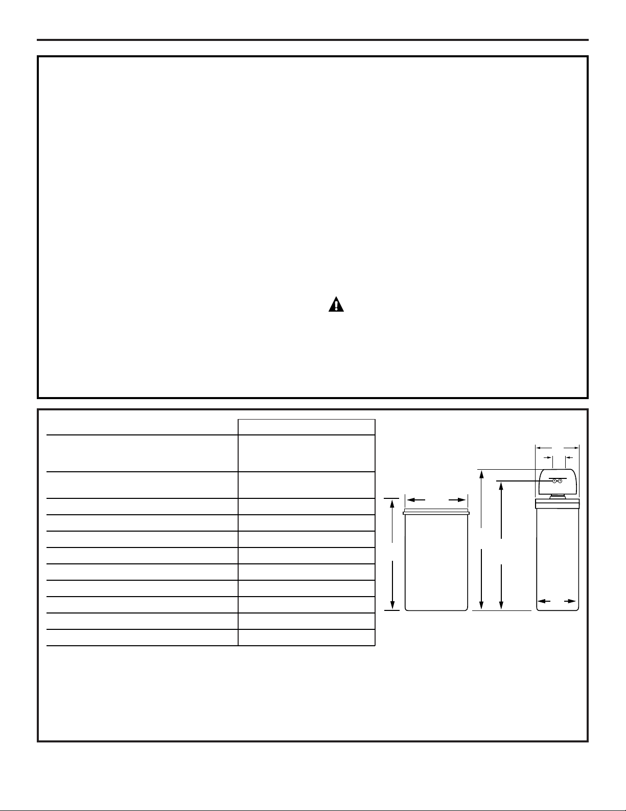
14″
11″
3
7
⁄
8
″
IN-OUT
38″
18″
59″
50
1
⁄2″
GNSM48F
Rated Capacity* 14,300 grains with 2.8 lbs of salt
37,700 grains with 10.4 lbs of salt
48,000 grains with 18.1 lbs of salt
Rated Efficiency** 5,110 grains/lb.
@ 2.8 lbs. of salt
Amount of High Capacity Resin (lbs/cu. ft) 69.2/1.33
Resin Tank Nominal Size (in., dia. x height) 10 x 47
Service Flow Rate (gpm) 11.8
Water Supply Maximum Hardness (gpg) 120
Water Supply Maximum Clear Water Iron (ppm)*** 13
Water Pressure Limits (min.–max. psi)**** 20–125
Pressure Drop at Rated Service Flow (psig) 15
Water Temperature Limits (min.–max. °F) 40–120
Maximum Flow Rate to Drain (gpm) 2.3

13
About the water softener system.
ge.com
Service
When the water softening system is providing
soft water, it is called “Service.” During service,
hard water flows from the house main water pipe
into the water softening system. Inside the water
softening system resin tank is a bed made up of
thousands of tiny, plastic resin beads. As hard
water passes through the bed, each bead
attracts and holds the hard minerals. This is
called ion-exchanging. It is much like a magnet
attracting and holding metals. Water without
hard minerals (soft water) flows from the water
softening system and to the house pipes.
After a period of time, the resin beads become
coated with hard minerals and they have to be
cleaned. This cleaning is called recharge.
Recharge is started at 2:00 AM (factory setting)
by the water softening system control, and
consists of five stages or cycles. These are FILL,
BRINING, BRINE RINSE, BACKWASH and FAST
RINSE.
For emergency needs, hard water is available
to the home during the recharge cycles.
However, you should avoid using HOT water
because the water heater will fill with the hard
water.
Automatic Hard Water Bypass During Recharge
Fill
Salt dissolved in water is called brine. Brine is
needed to clean the hard minerals from resin
beads. To make the brine, water flows into the
salt storage area during the fill stage.
Brining
During brining, brine travels from the salt storage
area into the resin tank. Brine is the cleaning
agent needed to remove hard minerals from the
resin beads. The hard minerals and brine are
discharged to the drain.
The nozzle and venturi create a suction to move
the brine, maintaining a very slow rate to get the
best resin cleaning with the least salt.
Brine Rinse
After a pre-measured amount of brine is used,
the brine valve closes. Water continues to flow in
the same path as during brining, except for the
discontinued brine flow. Hard minerals and brine
flush from the resin tank to the drain.
Backwash
During backwash, water travels up through
the resin tank at a fast flow rate, flushing
accumulated iron, dirt and sediments
from the resin bed and to the drain.
Fast Rinse
Backwash is followed by a fast flow of water
down through the resin tank. The fast flow
flushes brine from the bottom of the tank,
and packs the resin bed.
After fast rinse, the water softening system
returns to soft water service.
14
About the water softener system.
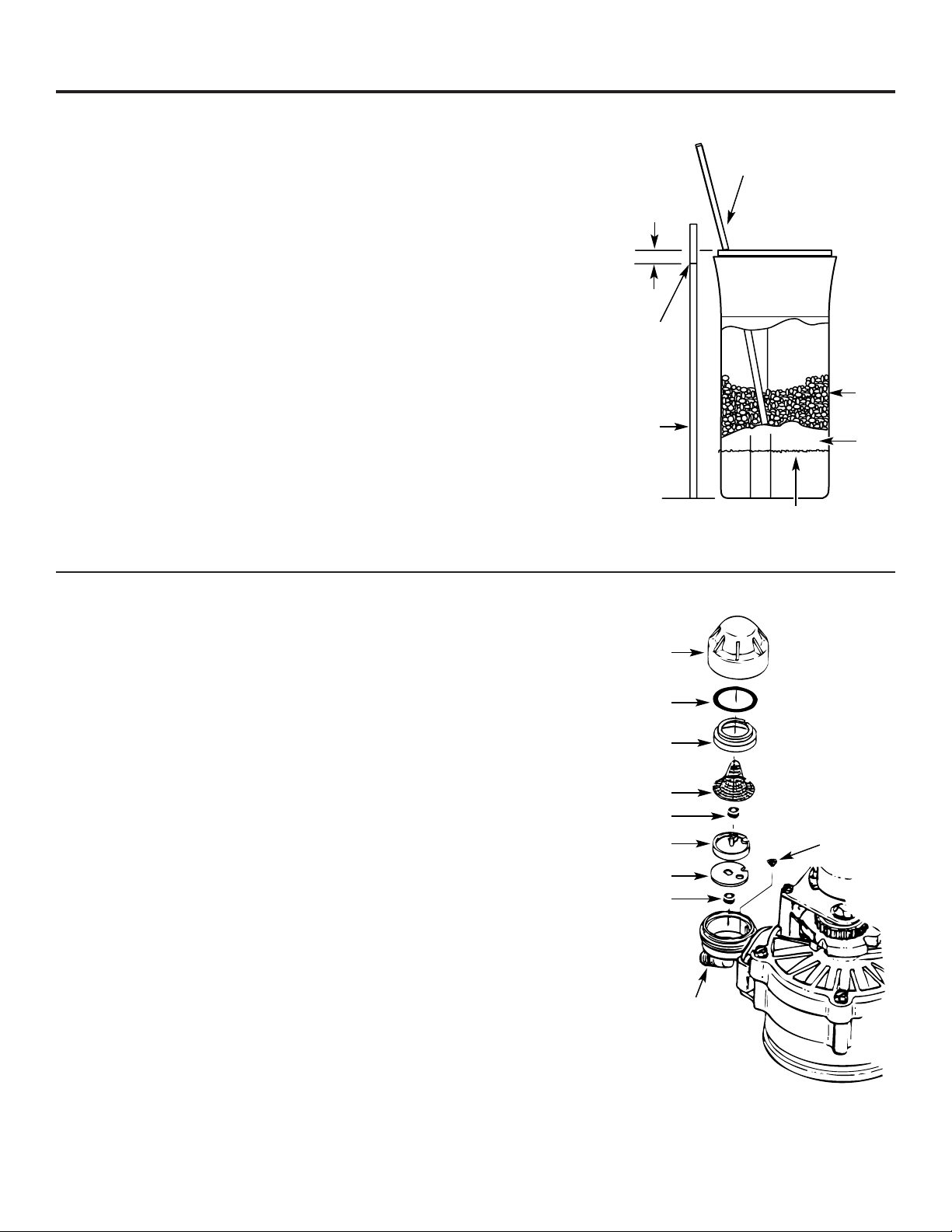
Breaking a Salt Bridge
Sometimes, a hard crust or salt bridge forms in
the salt storage area. It is usually caused by high
humidity or the wrong kind of salt. When the salt
bridges, an empty space forms between the
water and salt. Then salt will not dissolve in the
water to make brine.
If the brine tank is full of salt, it is hard to tell
if you have a salt bridge. Salt is loose on top, but
the bridge is under it. The following is the best
way to check for a salt bridge.
Salt should be loose all the way to the bottom of
the tank. Take a broom handle or like tool, and
carefully push it down into the salt, working it up
and down. If the tool strikes a hard object (be
sure it’s not the bottom or sides of the tank), it’s
most likely a salt bridge. Carefully break the
bridge with the tool. Do not pound on the walls
of the tank.
If the wrong kind of salt made the bridge, take it
out. Then fill the tank with nugget or pellet salt
only. In humid areas, it is best to fill with less salt,
more often to prevent a salt bridge from forming.
A clean nozzle and venturi is needed for the
water softening system to work properly. This
small unit makes the suction to move brine from
the salt storage area to the resin tank during
recharge. If it becomes plugged with sand, dirt,
etc., the water softening system will not work
and you will get hard water.
To get to the nozzle and venturi, remove the
water softening system top cover. Be sure the
water softening system is in service cycle (no
water pressure at nozzle and venturi). Then, while
holding the nozzle and venturi housing with one
hand, remove the cap. Lift out the screen support
and screen, then the nozzle and venturi. Wash
and rinse the parts in warm water until clean. If
needed, use a small brush to remove iron or dirt.
Also check and clean the gasket.
NOTE: Some models have a small flow plug
located in the nozzle and venturi, and/or a small
cone shaped screen in the housing. Be sure to
check and clean these parts, if your model is
so equipped.
Carefully replace all parts in the correct
order. Lightly lubricate the o-ring seal with clean
silicone grease or petroleum jelly and place in
position. Install and tighten the cap, by hand
only. Do not overtighten the cap.
Cleaning the Nozzle and Venturi Assembly
Push tool into salt
bridge to break
Pencil
mark
Broom
handle
Salt
Salt
bridge
Water level
1″–2″
IMPORTANT: Be sure small holes in the gasket are
centered directly over the small holes in the nozzle and
venturi housing.
*Install with numbered side up, concave side down.
Cap
O-ring seal
Screen
support
Screen
Screen
Nozzle &
Venturi
Nozzle &
Venturi
housing
Gasket
*Flow
plug
*Flow plug

15
ge.com
If electrical power to the water softening system is interrupted, the control display is blank, but the
control keeps correct time for about 72 hours. When power is restored, you have to reset the present
time only if the display is flashing. All other settings are maintained and never require resetting
unless a change is desired.
If the time is flashing after a long power outage, the water softening system continues to work as it
should to provide you with soft water. However, regenerations may occur at the wrong time of day
until you reset the control to the correct time of day.
Normal Operation, Timer Display
During normal operation, the present time of day and AM or PM show in the control display
area. When the demand computer determines a regeneration is needed, RECHARGE TONIGHT
begins to flash in the display, along with the present time. RECHARGE TONIGHT flashes until
the next regeneration start time, then changes to RECHARGE NOW, which flashes until the
regeneration is over. The display also shows the current cycle in the regeneration process.
When the valve is in transition between cycles, both indicators flash.
Feature: Optional Recharge Controls
Sometimes, a manually started regeneration (recharge) may be desired or needed.
Two examples:
■ You have used more water than usual (house guests, extra washing, etc.) and you may run out
of soft water before the next regeneration.
■ You did not refill the storage tank with salt before it was all gone.
Use one of the following features to start a regeneration immediately, or at the next preset
regeneration start time.
RECHARGE NOW
Press and hold the TOUCH or HOLD button until RECHARGE NOW starts to flash in the control
display area. The water softening system begins an immediate regeneration and, when over in
about two hours, you will have a new supply of soft water. Once started, you cannot cancel this
regeneration.
RECHARGE TONIGHT
Touch (do not hold) the TOUCH or HOLD button. RECHARGE TONIGHT flashes in the control display
area. A regeneration will occur at the next preset regeneration start time. If you decide to cancel
this regeneration, touch the same button once more.
Feature: Program Memory
RECHARGE TONIGHT
RECHARGE NOW
TOUCH
HOLD
or
About the water softener system.
The timer computer has a self-diagnostic function for the electrical system (except input power and
water meter). The computer monitors the electronic components and circuits for correct operation.
If a malfunction occurs, an error code appears in the timer display.
The chart on Error Codes shows the error codes that could appear and possible defects for each code.
While an error code is displayed, the TOUCH or HOLD and DATA buttons remain operable so you can
perform the Manually Initiated Electronic Diagnostics.
Feature/Service: Automatic Electronic Diagnostics
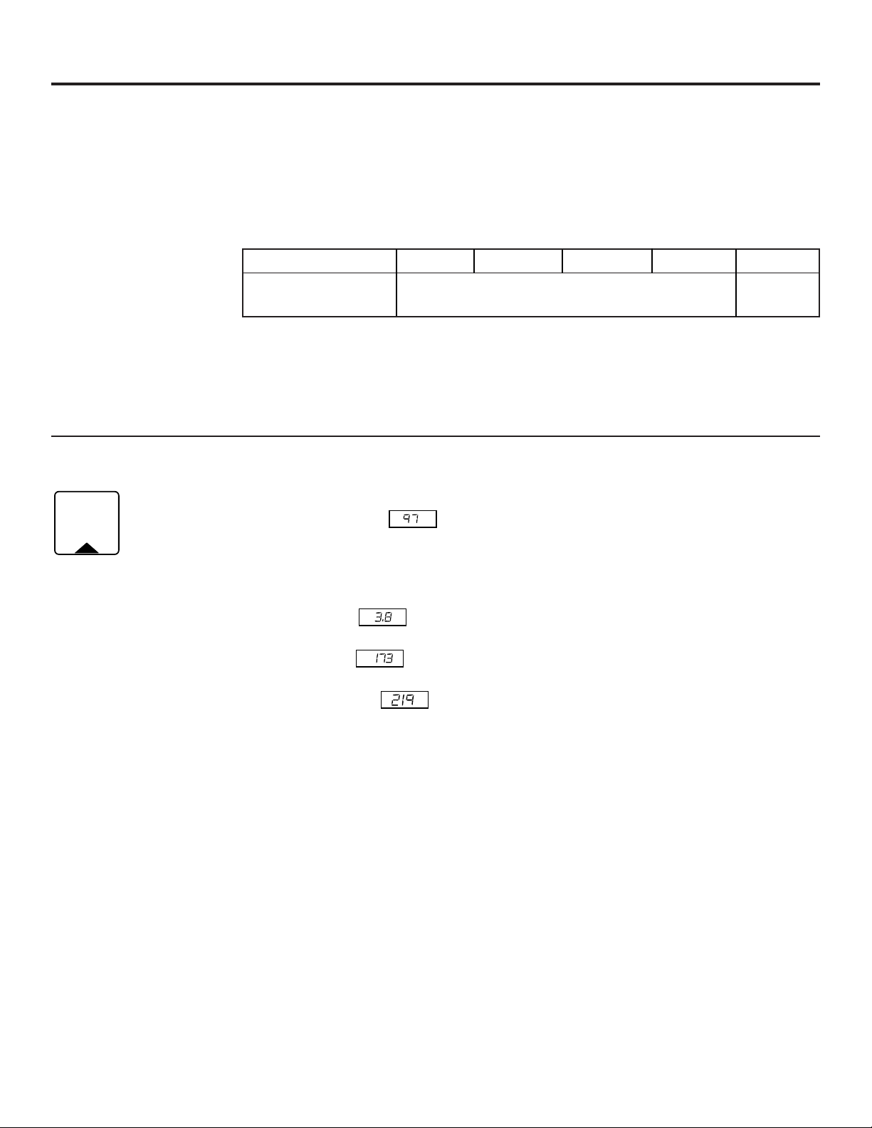
By continuing to press the DATA button, you can scan through four displays of operational
information. This data appears in the bottom portion of the display area.
REMAINING CAPACITY — This is the percentage of water softening capacity remaining.
Immediately after a regeneration, 100% shows. As water is used, the percentage decreases until the
next regeneration. During regenerations, the percentage increases.
NOTE: Zero (%) shows until after the first regeneration begins, after connecting to
electrical power.
FLOW RATE, GPM— When using soft water, this display shows the flow rate passing through
the softener (in gallons per minute). Zero shows if water is not passing through the softener.
GALLONS TODAY— Each day, beginning at midnight, the timer keeps a running count of the
total gallons of water that have passed through the softener.
AVG. DAILY GALLONS— The figure displayed is the average gallons of water used by the
household each day over the past seven day period.
NOTE: If preferred, you can set the timer to show the reading in liters instead of gallons. If GALLONS
TODAY or AVG. DAILY GALLONS exceeds 1999, a (x10) indicator appears; this means you must
multiply the number shown by ten.
Feature: Other Data Displays
ERROR CODE DISPLAYED ERR 01 ERR 02 ERR 03 ERR 04 ERR 05
POSSIBLE DEFECT ➨ motor inoperative ➨ wiring harness, or connection to switch ➨ timer (PWA)
➨ position switch ➨ valve defect causing high torque
To remove an error code: (1) Unplug transformer.
(2) Correct defect.
(3) Plug transformer in.
(4) Wait for at least 6 minutes. The error code will return if the reason
for the error code was not corrected.
DATA
REMAINING CAPACITY
FLOW RATE GPM
GALLONS TODAY
AVG. DAILY GALLONS
WATER
MANAGEMENT
SYSTEM
AVG DAILY GALLONS
WATER MANAGEMENT SYSTEM
GALLONS TODAY
WATER MANAGEMENT SYSTEM
GPM
FLOW RATE
CAPACITY
%
WATER MANAGEMENT SYSTEM
16
17
ge.com
Timer/Softener, Service Checkout Procedure
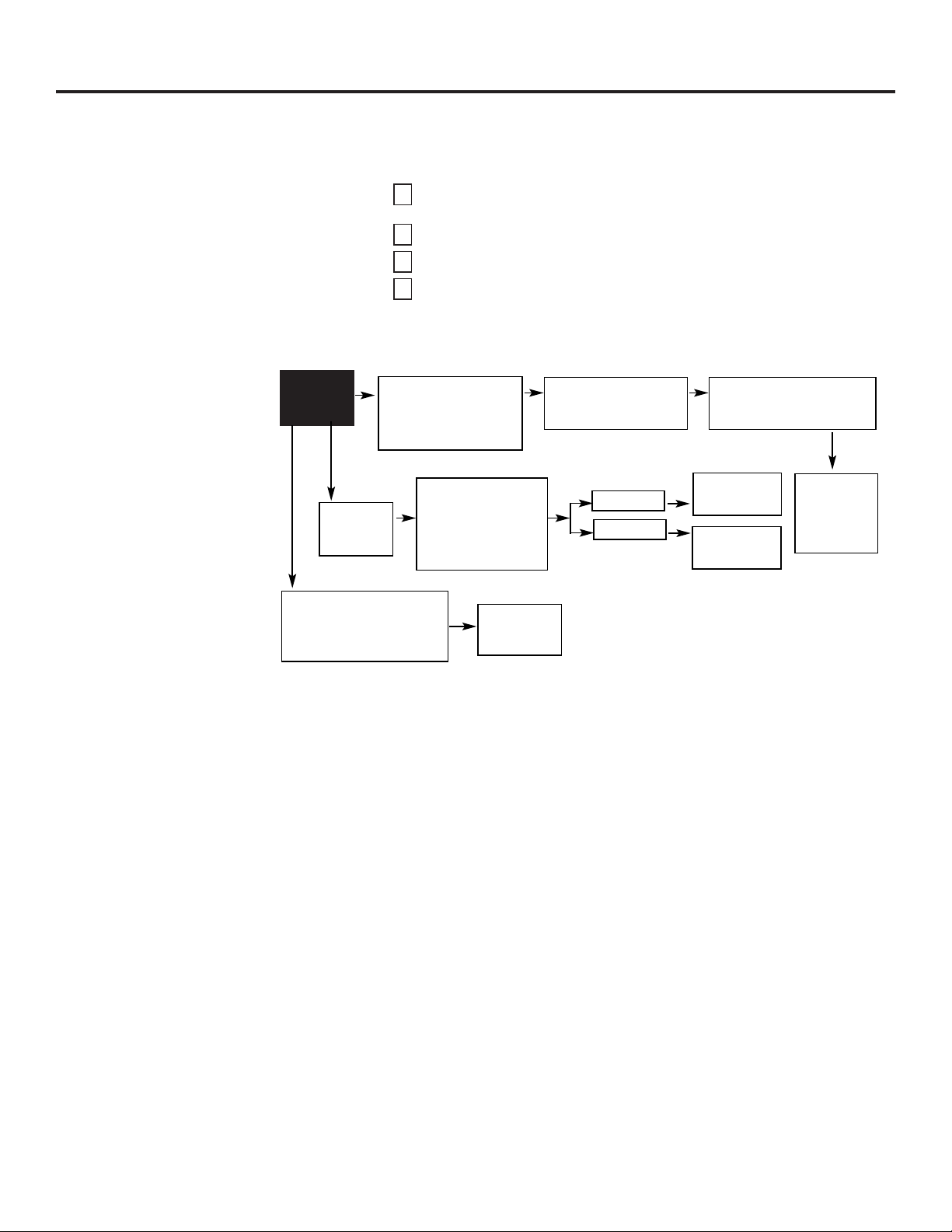
If you are not getting soft water, and an error code is not displayed, use the procedures below to
find the problem. First make the following visual checks:
VISUAL CHECKS: Is there electrical power to the outlet the water softening system transformer
is plugged into?
Is there sufficient salt in the storage tank?
Is the plumbing bypass valve directing water for soft water service?
Is the valve drain hose open to the drain, not more than 8′ above the
softener, and unobstructed? If hose is above 8′, see page 8, section 5.
If you do not find a problem with the visual checks, continue below.
4
3
2
1
NO SOFT
WATER
TIMER SHOWS
WRONG TIME AND
DAY, AND/OR IS
FLASHING.
TIMER
DISPLAY
BLANK.
TIMER DISPLAY SHOWS
CORRECT TIME AND DAY
AND IS STEADY.
Check electrical
power to control
(outlet, transformer,
power cable, all
connections).
Do manual
diagnostics.
NO POWER
POWER OK
REPAIR AS
NEEDED
TIMER
DEFECTIVE
Do manual
diagnostics
to verify
proper
function.
Electrical power was
off. Reset the correct
time of day.
Investigate reason for
power loss.
About the water softener system.
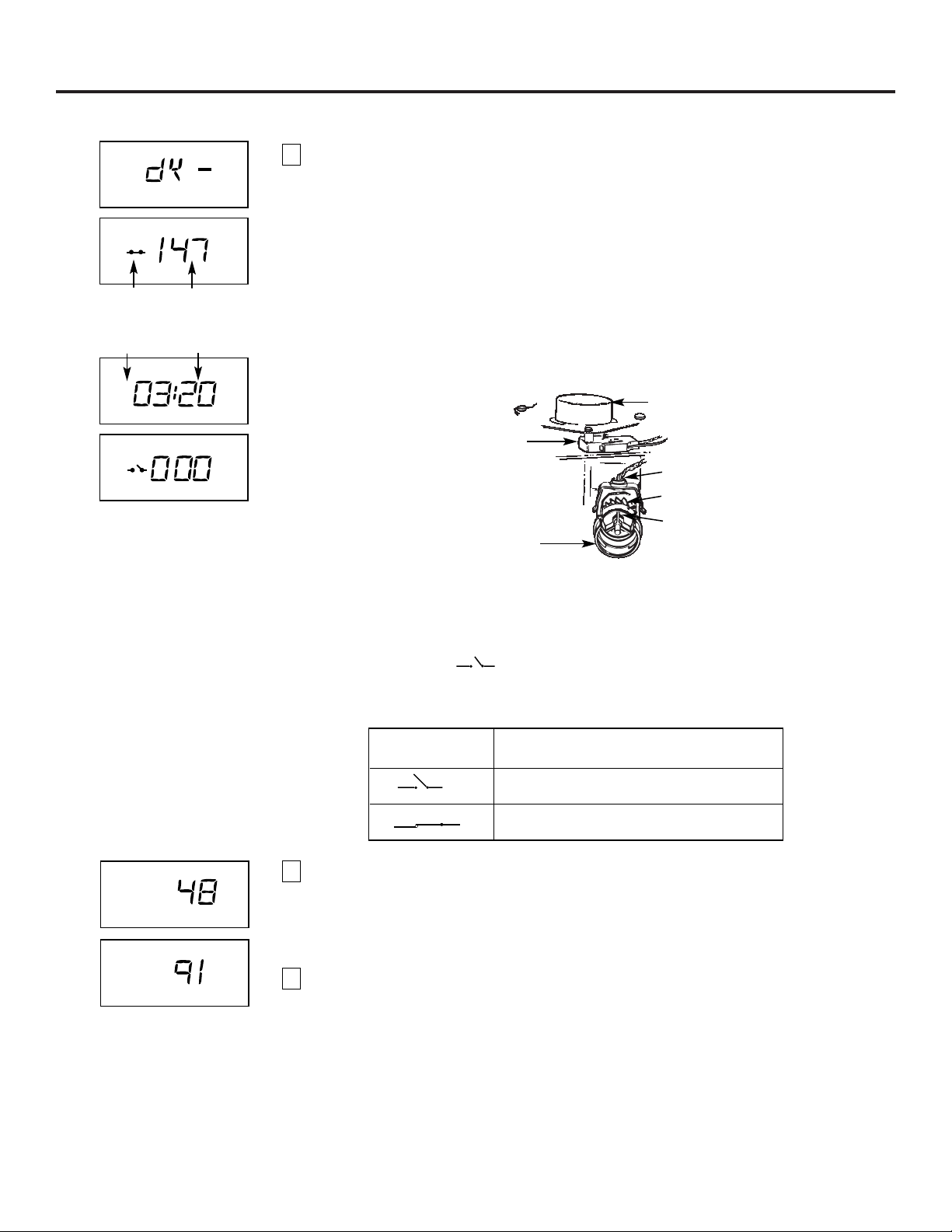
Service: Manually Initiated Electronic Diagnostics
To enter diagnostics, press and hold the DATA button until the display appears as shown.
NOTE: If the softener is in the middle of a regeneration, top part of the display shows the cycle
of regeneration and minutes of the cycle remaining. If two cycle names are flashing, the valve
is in transition between the cycles.
A The three digits under WATER MANAGEMENT SYSTEM indicate water meter operation
as follows:
■ 000 (steady) = soft water not in use…no flow through the meter.
—OPEN A NEARBY SOFT WATER FAUCET—
■ 000 to 140 (continual) = repeats display for each gallon of water passing through the
meter.
If you don’t get a reading in the display, with faucet open, pull the sensor from the valve outlet
port. Pass a small magnet back and forth in front of the sensor. You should get a reading in the
display. If you get a reading, shut off water supply, unhook the in and out plumbing and check
the turbine for binding.
B This display segment ( ) , in the following chart, indicates an open POSITION switch.
Use the
TOUCH or HOLD button to manually advance the valve into each cycle and check
correct switch operation.
Press the DATA button again. This diagnostic display shows the total number of recharges (top)
since the timer was connected to electrical power.
The number of days since the timer was connected to electrical power is shown in the bottom
part of the display. If over 1999 days, a (x10) indicator shows, meaning you must multiply the
number shown by 10.
Press DATA once again to return the present time to the display.
3
2
1
CORRECT SWITCH
DISPLAYS VALVE CYCLE STATUS
Valve in service, fill, brining, backwash
or fast rinse position.
Valve rotating from one position to another.
RECHARGE
WATER MANAGEMENT SYSTEM
DAY
x 10
LAST RECHARGE
On
WATER MANAGEMENT SYSTEM
Turbine
TIME
Fill
WATER MANAGEMENT SYSTEM
Turbine
Switch Turbine
count
Valve Minutes of cycle
position remaining
18
Motor
Turbine
Turbine
support &
shaft
Position
switch
Valve
outlet
Sensor
housing

Service: Manually Advance Regeneration Check
This check verifies proper operation of the valve motor, brine tank fill, brine draw, regeneration
flow rates and other controller functions. First, make the initial checks and the manually initiated
electronic diagnostics.
NOTE: The face plate display must show a steady time (not flashing).
Press the TOUCH or HOLD button and hold for three seconds. RECHARGE NOW begins
to flash as the water softening system enters the fill cycle of regeneration. Remove the
brinewell cover and, using a flashlight, observe fill water entering the brine tank.
If water does not enter the tank, look for an obstructed nozzle, venturi, fill flow plug, brine
tubing or brine valve riser pipe.
After observing fill, press the TOUCH or HOLD button to move the water softening system into
brining. A slow flow of water to the drain will begin. Verify brine draw from the brine tank by
shining a flashlight into the brinewell and observing a noticeable drop in the liquid level.
NOTE: Be sure a salt bridge is not preventing salt contact with water.
If the water softening system does not draw brine, check:
■ nozzle and/or venturi dirty or defective.
■ nozzle and venturi not seated properly on gasket.
■ restricted drain (check drain fitting and hose).
■ defective nozzle and venturi seal.
■ other inner valve defect (rotor seal, rotor & disc, wave washer, etc.).
NOTE: If water system pressure is low, an elevated drain hose may cause back pressure, stopping
brine draw.
Again, press the TOUCH or HOLD button to move the softener into backwash. Look for a fast
flow of water from the drain hose.
A slow flow indicates a plugged top distributor, backwash flow plug or drain hose.
Press TOUCH or HOLD to move the water softening system into fast rinse. Again look for a fast
drain flow. Allow the water softening system to rinse for a few minutes to flush out any brine
that may remain in the resin tank from the brining cycle test.
To return the water softening system to service, press TOUCH or HOLD.
5
4
3
2
1
ge.com
19
About the water softener system.
20
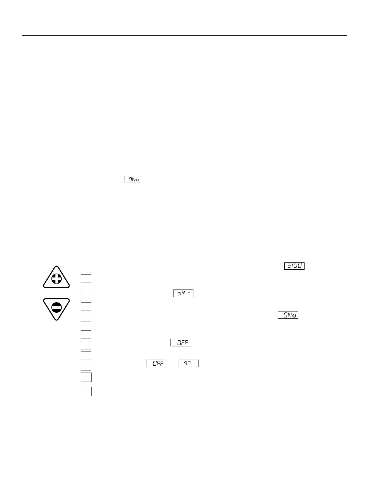
Service: Regeneration and Heavy Duty Backwash
NOTE: Each of the following functions has a factory-set default value. The defaults are: Regeneration start time
–2:00AM ; Maximum days between regenerations –0 (display shows dY–); Efficiency mode –ON; Heavy duty
backwash –OFF. The defaults are suitable for most installations. However, depending on water supply quality,
household peak water use hours, etc., adjustment is available to meet specific needs. To make a change, read
and do the following.
Regeneration (Start) Time: At the 2:00 AM regeneration start time, the water
softening system begins
regeneration at that time, ending at about 4:00 AM. This is a good time in most households because water is not
in use (see Automatic Hard Water Bypass During Regeneration section). If a different time would be better for
your
needs, do steps 1, 2, 3, 5, 7, 9 and 11 below to change the starting hour.
Maximum Days Between Regeneration: The default setting (dY–) allows the timer to control regeneration
frequency based on water usage readings from the water meter. It provides the most economical operation.
You can set a maximum time (in days) between regenerations. For example, no more than three days will pass
without a regeneration occurring if you set dY 3 in the display. A 1 to 7 day setting is available. To make a
change from the default setting, do steps
1, 3, 4, 5, 7, 9 and 11
below.
Efficiency Mode: When this feature is ON, the unit will operate at salt efficiencies of 4000 grains of harness per
pound of salt or higher. (May recharge more often using smaller salt dosage and less water). When this is ON,
the efficiency icon will show in the lower right hand corner of the display. To make a change for the
default setting, do steps 1, 3, 5, 6, 7, 9 and 11 below.
Heavy Duty Backwash: When set to ON, the backwash cycle of regeneration will be 10 minutes long instead
of the normal seven minute length. This is beneficial on some water supplies high in iron or sediment content.
To conserve water, on clean supplies, be sure the default setting OFF shows. To change this setting, do steps
1,
3, 5, 7, 8, 9 and 11
below.
Auto Regeneration When Capacity is Low: The softener will regenerate at the regeneration time only.
Although the control has a look-forward feature which anticipates normal demand, an unusually high usage
may result in a loss of softening capacity. Turning the feature ON will cause the softener to go into a
regeneration cycle when 97% of the softening capacity has been used. To change settings, do steps
1, 3, 5, 7, 9,
10 and 11 below.
Beginning from the present time display, press and hold in the SET button until begins to flash.
Press the UP or DOWN button to display the desired start time. The UP button moves the time ahead; the
DOWN button moves the time backward.
Press the SET button again, and flashes.
To set a maximum time (in days) between regenerations, press the UP or DOWN button.
Press the SET button again and the ON flashes and the efficiency mode icon
shows in the lower right hand corner of the screen.
Use the UP or DOWN arrows to toggle the efficiency mode either ON or OFF.
Press the SET button to display .
Use the UP button to change the display to ON to increase the backwash time, if desired.
Press the SET button and alternately flashes.
Use the UP button to turn Auto Regeneration cycle to ON.
Press the SET button a final time to return to present time of day.
11
10
9
8
7
6
5
4
3
2
1
SET
RECHARGE
AM
TIME
RECHARGE
Heavy
Bkwash
Heavy
Bkwash
CAPACITY
%
WATER MANAGEMENT SYSTEM
E
Heavy
Bkwash
E
Heavy
Bkwash
ge.com
21
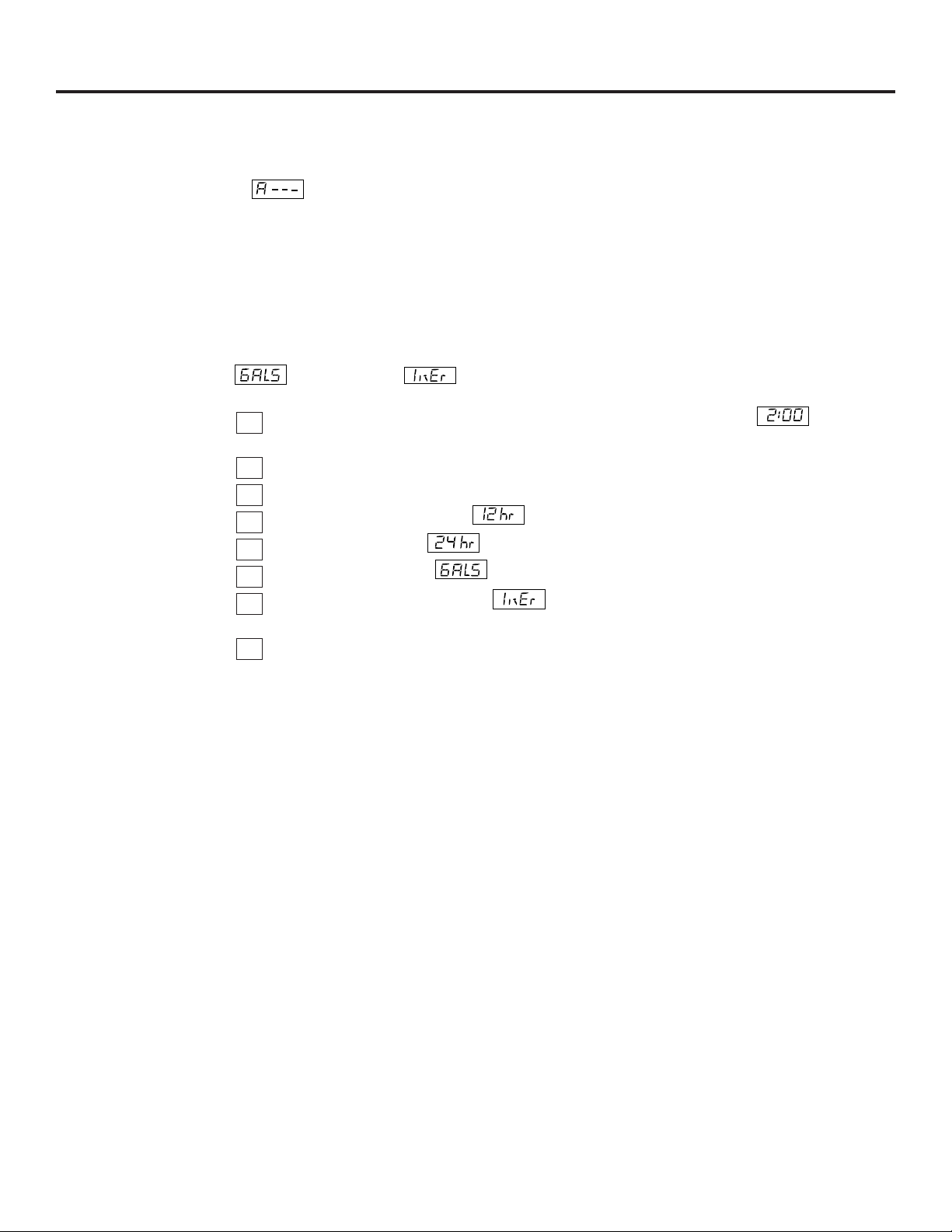
Setting: Model Code, 12 or 24 Hour Clock and Gallons or Liters Measured
Model Code: The timer must have the right model code set to operate the water softening system
correctly. The correct code setting for the GNSM48F is A-39.
If is flashing in the display, do steps 3, 4, 6 and 8 below.
To check for the correct code setting for your model, and to reset it if needed, do steps 1, 2, 3, 4, 6
and 8 below.
NOTE: The hour clock and water measure have factory-set default values. The defaults are:
12 or 24 hour clock –12; Gallons or liters measure — gallons.
12 or 24 Hour Clock: With 12 hr set, all time displays are in standard clock time …12:00 AM to 11:59
PM. If 24 hr is set, time displays are in military time …0100 (1:00 AM) to 0000 (midnight). To change
from the 12 hr setting, do steps 1, 2, 4, 5, 6 and 8.
Gallons or Liters Measure: All water flow rate and usage displays are in gallons with the default
setting. If reset to , the same displays are shown in liters. Use steps 1, 2, 4, 6, 7
and 8 to change.
Beginning from the present time display, press and hold in the SET button until
(or as otherwise set) begins to flash.
Press and hold in the SET button again.
If setting is other than A-39, use the UP or DOWN button to set the correct number.
Press the SET button again and flashes.
To change the display to use the UP button. Use the DOWN button to reset to 12 hr.
Press the SET button and flashes.
Use the UP button to change to the setting. Use the DOWN button to return to the
gallon setting.
Press the SET button a final time to return to the present time display.
8
7
6
5
4
3
2
1
TIME
TIME
RECHARGE
AM
TIME

Care and cleaning of the water softening system.
Brine (salt dissolved in water) is needed for each
and every recharge. The water for making brine
is metered into the salt storage area by the
water softening system valve and control.
However, you must keep the tank supplied
with salt.
When to refill with salt: Check the salt level a
few weeks after you install the water softening
system and every week after that. Refill when
the brine tank is from 1/3 to 1/2 full. Never allow
the water softening system to use all the salt
before you refill it. Without salt, you will soon
have hard water.
Use clean water softening salts only, at least
99.5% pure. NUGGET, PELLET or coarse SOLAR
salts are recommended. Do not use rock, block,
granulated or ice cream making salts. They
contain dirt and sediments, or mush and cake,
and will create maintenance problems.
CAUTION:
Water softening salt
with iron removing additives: Some salts
may have an additive to help the water
softening system handle iron in the water
supply. Although this additive may help to
keep the water softening system resin clean,
it may also release corrosive fumes that
weaken and shorten the life of some water
softening system parts. GE recommends
using only Diamond Crystal
®
Red•Out
®
brand salt.
Checking the Salt Storage Level and Refilling
Your water softening system takes hardness
minerals (calcium and magnesium) out of
the water. Also, it can control some (see the
Specification Guidelines section) “clear water”
iron. With clear water iron, water from a faucet
is clear when first put into a glass. After 15 to 30
minutes, the water begins to cloud or turn rust
colored. A water softening system will not
remove any iron that makes the water cloudy
or rusty as it comes from the faucet (called red
water iron). To take red water iron out of water,
or over the maximum of clear water iron,
an iron filter or other equipment is needed.
GE recommends using only Diamond Crystal
®
Red•Out
®
brand salts with Iron Fighter
®
additive
to help keep the resin bed clean of clear iron. If
your water supply has clear water iron, periodic
resin bed cleaning is needed. GE recommends
using Super Iron Out
®
brand resin bed cleaner
to thoroughly clean your resin bed if your iron
content is high. Clean the bed at least every six
months, or more often if iron appears in the soft
water between cleanings.
IMPORTANT: It is important to mix the resin bed
cleaner with water (following the manufacturer’s
instructions), pour it into the brinewell tube
(see page 5) and recharge the softener
immediately. Do not pour the resin bed cleaner
in with the salt, as it will not be as effective in
cleaning the resin, and can cause damage to
the softener if it is left in the brine tank for an
extended period due to the corrosive gases
that are formed.
Cleaning Iron Out of the Water Softening System
22
23
Troubleshooting Tips
Save time and money! Review the chart on this page first
and you may not need to call for service.
Problem Possible Causes What To Do
No soft water Faucet or fixture where sample was •
To conserve salt, the installer
may have isolated some fixtures
taken not plumbed to soft water.
(outside faucets, toilets, etc.)
from soft water. From the outlet
NOTE:
Be sure sample is from a faucet of the water softening system, trace the water flow path,
that does not mix soft and hard water. in house plumbing. If soft water is not directed to a faucet
For example, a single lever kitchen faucet, or
fixture where wanted, consult a plumber.
if the cold side is plumbed to hard water.
No salt in the brine tank or • Check for a salt bridge or, if the tank is empty, refill with
salt bridged recommended salt. Press (for 3 seconds) the TOUCH or HOLD
button to start an immediate regeneration and restore soft
water supply.
Transformer unplugged at wall outlet or
• Check for a loss of electrical power to the water softening
power cable to softener not connected. system, due to any of these conditions and correct as needed.
Fuse blown or circuit breaker popped With the power supply restored, observe the faceplate time
on circuit to electrical outlet. display and read Programming the Control section.
Electrical outlet on a circuit that can
NOTE: The electrical outlet for the softener should be
continuously
be switched off
live
so it cannot be accidentally switched off.
Manual bypass valve in bypass position • Be sure the bypass valve stem
is positioned properly, with the
knob in the OUT position. Observe i
nstructions on the decal
at the end of the stem.
Valve drain hose pinched, plugged, •
Any restriction in this drain hose
may prevent proper
elevated too high or otherwise
operation of the
nozzle and venturi and reduce or prevent
restricted brine draw during recharge.
Nozzle and venturi dirty, incorrectly • Refer to Cleaning the Nozzle and Venturi Assembly
instructions.
assembled or damaged
With water pressure to the
water softening system off, take the
nozzle assembly apart. Inspect, clean and replace as needed.
Any foreign particle(s), scratches, nicks, etc., in the passages can
prevent operation. Be sure holes in the gasket are centered over
holes in the housing.
NO SOF
T WATER – Most Common Problems:
Check the following before calling for service:
•
Not enough salt—should be at least 1/3 full.
•
Bypass valve in “Bypass” position—knob should be in the “OUT” (service) position.
•
Hardness setting too low. Check hardness setting and adjust. Verify hardness of supply
water—from local water company, water test or call the GE Answer Center.
•
Salt Bridge—salt solidifies above water level so that brine water is not in contact with
salt. See the Breaking a Salt Bridge section.
Before you call for service… ge.com
Problem Possible Causes What To Do
Water hard sometimes Using hot water while the water • Avoid using hot water during water softening system
softening system is regenerating recharge because the water heater will refill with hard water.
See Automatic Hard Water Bypass During Recharge section,
page 13.
Control HARDNESS number setting • Press and release the SET button until HARDNESS shows in the
too low display. Be sure the number shown is the same as the actual
grains per gallon hardness of your water supply. See the Control
section if a change in the setting is needed.
Grains of hardness in your water •
Water hardness can change
over time, especially in well water.
supply have increased To check, have the water tested by a water analysis laboratory
or call your local water department. Adjust the HARDNESS
number setting as needed.
Water feels slippery Absence of hardness minerals • This is normal. Hardness in water gives it the abrasive feel
after installation of you may have been accustomed to. The slippery feel is the
water softening system clean feel of soft water.
Water softening system Water softening system is a • Does not use much salt to regenerate—very efficient.
not using any salt “demand” unit
Possible salt bridge • See the About the Water Softener System section, page 14.
Possible plugged nozzle and venturi • See the About the Water Softener System section, page 14.
Water is blue color Acidic water in copper plumbing • Have the water tested at once.
after water softening
system was installed
Water softening system Meter turbine stuck • See the Service: Manually Initiated Electronics Diagnostics
not regenerating section for troubleshooting procedures, page 18.
• Call for service.
Sensor wire not plugged into • See the Service: Manually Initiated Electronics Diagnostics
the control section for troubleshooting procedures, page 18.
• Call for service.
No power to unit • Check the circuit breaker or fuses.
Mechanical defect • Call for service.
Cloudiness on glassware Combination of soft water and • This is called etching and is permanent. To prevent this
(automatic dishwashers) too much detergent from happening, use less detergent if you have soft water.
Wash glassware in the shortest cycle that will get them clean.
Excessive/high level Valve drain hose pinched, • Any restriction in this drain hose may prevent proper
of water in brine tank plugged, elevated too high operation of the nozzle and venturi and reduce or prevent
or otherwise restricted brine draw during recharge.
Nozzle and venturi dirty, incorrectly • See the Cleaning the Nozzle and Venturi Assembly section,
assembled or damaged page 14. With water pressure to the water softening system
off, take the nozzle assembly apart. Inspect, clean and
replace as needed. Any foreign particle(s), scratches, nicks,
etc., in the passages can prevent operation. Be sure holes
in the gasket are centered over holes in the housing.
Before you call for service…
24
Troubleshooting Tips

25
ge.com
Problem Possible Causes What To Do
Salty tasting or Unit not sanitized • Complete the Sanitization Procedures on page 12.
brown/yellow colored
• At completion of recharge cycle (approx. 2 hrs), run water
water after installation
from faucets to purge the salty water.
Low water pressure Check pressure.
• Drain height 8′ or less, pressure should be minimum of 20 psi.
• Drain height above 8′, pressure should be minimum of 50 psi.
Restricted drain hose • Clean and reconnect hose.
• Check for kinks in drain line.
Brown/yellow Unit was idle for a period of time • Complete the Sanitization Procedures on page 12.
colored water
Resin beads showing Cracked distributor • Call for service.
up in drinking water
and sink
Sounds you might hear Running water from the unit • This is normal.
into a drain during recharge
Water has air bubbles Air in system after installation • Will go away after it runs for a while.
and is cloudy
Error Code on control Wiring may have worked loose • See page 16 for details.
in the control
• Unplug transformer.
• Remove control cover, release clips on side.
• Check for loose/incorrect wiring connections to electronic
board or switch. Reconnect as required.
• Reassemble control cover.
• Plug in Transformer.
• Wait six minutes for Error Code to reappear.
• If Error Code reappears, call for service.

26
Notes.
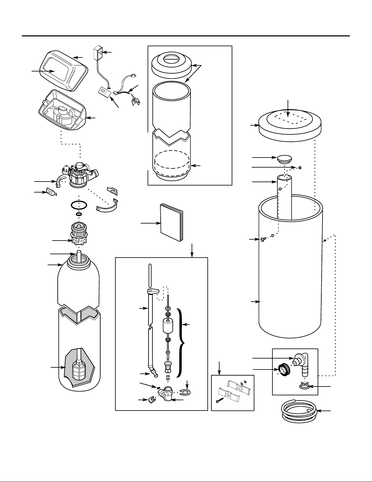
27
Parts list.
ge.com
LITERATURE
9
33
36
35
34
10
28
29
32
27
25
5
30
31
26
8
7
3
55
56
4
19
24
20
22
23
21
999
{
37
11
16
146
17
13
12
18
28
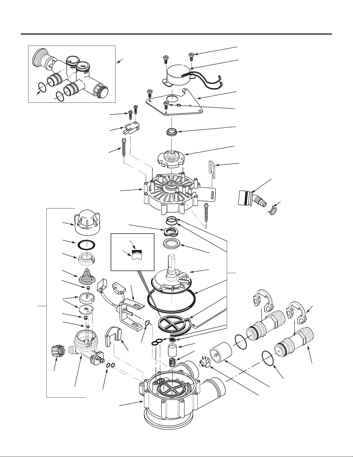
Parts list.
137
136
135
106
105
103
101
151
110
145
143
110
147
148
138
139
141
140
120
118
117
115
116
114
113
112
111
110
109
124
125
108
123
122
146
150
119
121
107
130
132
25
cross-section
view
seal
wear-strip

29
Parts catalog.
ge.com
GENERAL ELECTRIC PARTS CATALOG
G
N
S
M
4
8
F
REF. NO. GE PART NO. PART DESCRIPTION (03)
3 WS35X10001 O-RING SEAL KIT 1
4 WS34X10006 DECAL 1
5 WS07X10004 DRAIN HOSE – 20 FT 1
7 WS14X10002 DISTRIBUTOR TOP 1
8 WS14X10001 DISTRIBUTOR BOTTOM 1
9 WS01X10009 RESIN – 1 CU. FT. 1
10 WS32X10014 TANK RESIN – 10″ x 47″ 1
11 WS31X10015 COVER BOTTOM 1
12 WS31X10014 COVER FACEPLATE 1
13 WS21X10015 TIMER 1
16 WS26X10013 TRANSFORMER WITH CORD 1
17 WS31X10016 SHROUD AND BASE 1
18 WS33X10004 BASE 1
19 WS33X10005 COVER, BRINE TANK 1
20 WS31X10017 COVER, BRINEWELL 1
21 WS02X10021 NUT, #6–32 1
22 WS32X10002 BRINEWELL 1
23 WS02X10022 SCREW #6–32 1
24 WS32X10013 TANK BRINE 1
25 WS18X10003 CLAMP HOSE 1
26 WS22X10016 ADAPTOR HOSE 1
27 WS22X10017 GROMMET 1
28 WS35X10035 GROUND CLAMP KIT 1
29 WS15X10005 BRINE VALVE ASM. 1
30 WS35X10003 FLOAT, STEM AND GUIDE ASM. 1
31 WS03X10006 CLIP 1
32 WS15X10006 VALVE BODY, BRINE 1
33 WS03X10007 CLIP 1
34 WS03X10008 SCREEN 1
35 WS07X10002 TUBING ASM. 1
36 WS07X10003 TUBE BRINE 1
37 WS34X10007 DECAL 1
55 WS28X10003 RETAINER CLAMP 2
56 WS28X10007 CLAMP 1
101 WS02X10023 SCREW, #4–24 x 3/4 2
103 WS21X10003 SWITCH 1
105 WS02X10024 SCREW, #10 x 2 5/8 8
106 WS31X10013 COVER VALVE 1
107 WS03X10034 WASHER WAVE 1
108 WS26X10010 ROTOR AND DISC 1
109 WS19X10010 CAP 1
110 WS03X10011 SEAL, O-RING 1″ x 1/8″ 5
111 WS19X10005 SUPPORT SCREEN 1
112 WS03X10013 SCREEN 1
113 WS22X10036 FLOW PLUG, .15 GPM 1
114 WS08X10006 GASKET, NOZZLE/VENT 1
115 WS03X10015 SCREEN CONE 1

30
Parts catalog.
GENERAL ELECTRIC PARTS CATALOG
G
N
S
M
4
8
F
REF. NO. GE PART NO. PART DESCRIPTION (03)
116 WS22X10021 PLUG, FILL FLOW, .3 GPM 1
117 WS03X10017 NUT FERRULE 1
118 WS15X10034 NOZZLE/VENTURI BODY 1
119 WS03X10018 RETAINER 1
120 WS03X10019 SEAL, O-RING 1/4″ x 3/8″ 2
121 WS15X10025 BODY VALVE 1
122 WS03X10020 SPRING 1
123 WS22X10029 PLUG, DRAIN SEAL 1
124 WS15X10036 NOZZLE/VENTURI ASM. 1
125 WS03X10043 SPRING BEARING 1
130 WS35X10020 SEAL KIT 1
132 WS22X10058 ADAPTOR, DRAIN HOSE 1
135 WS03X10033 CLIP, DRAIN 1
136 WS26X10008 CAM AND GEAR 1
137 WS26X10009 BEARING 1
138 WS26X10007 PLATE MOTOR 1
139 WS02X10028 SCREW, #6–20 x 3/8″ 3
140 WS26X10006 MOTOR ASM. 1
141 WS02X10016 SCREW, #6–20 x – 7/8″ 2
143 WS60X10011 TUBE INSTALLATION 2
145 WS60X10008 CLIP 2
146 WS28X10018 HARNESS WIRE SENSOR ASM. 1
147 WS19X10008 TURBINE SUPPORT 1
148 WS19X10009 TURBINE 1
150 WS03X10024 SEAL, O-RING 1
151 WS15X10026 VALVE BY-PASS ASM. 1
998 WS35X10048 INSTALL KIT – GNSM48F 1
999 49–50179 PM MANUAL USE & CARE/ 1
INSTALLATION
31
What Is Not Covered:
For The Period Of: We Will Replace:
One Year Any part of the Water Softening System which fails due to a defect in materials or workmanship.
From the date of the During this limited one-year warranty, GE will also provide, free of charge, all labor and related
original purchase service to replace the defective part.
Three Years The electronic monitor, if it fails due to a defect in materials or workmanship. During this
From the date of the three-year limited warranty, you will be responsible for any labor or related service costs.
original purchase
Ten Years A replacement brine tank or cabinet, if either fails due to a defect in materials or workmanship.
From the date of the During this ten-year limited warranty, you will be responsible for any labor or related service costs.
original purchase
■ Service trips to your home to teach you how to use
the product.
■ Improper installation, delivery or maintenance.
■ Failure of the product if it is abused, misused, altered, used
commercially or used for other than the intended purpose.
■ Use of this product where water is microbiologically unsafe
or of unknown quality, without adequate disinfection before
or after the system. Systems certified for cyst reduction may
be used on disinfected water that may contain filterable
cysts.
■ Replacement of house fuses or resetting of circuit breakers.
■ Damage to the product caused by accident, fire, floods or
acts of God.
■ Incidental or consequential damage caused by possible
defects with this appliance, its installation or repair.
■ Product not accessible to provide required service.
This warranty is extended to the original purchaser and any succeeding owner for products purchased for home use within
the USA. If the product is located in an area where service by a GE Authorized Servicer is not available, you may be
responsible for a trip charge or you may be required to bring the product to an Authorized GE Service location for service.
In Alaska, the warranty excludes the cost of shipping or service calls to your home.
Some states do not allow the exclusion or limitation of incidental or consequential damages. This warranty gives you
specific legal rights, and you may also have other rights which vary from state to state. To know what your legal
rights are, consult your local or state consumer affairs office or your state’s Attorney General.
Warrantor: General Electric Company. Louisville, KY 40225
GE Water Softening System Warranty.
All warranty service provided by our SmartWater
™
Authorized Servicer
Network. To schedule service, call 800.952.5039 (U.S.) or 866.777.7627
(Canada). Please have serial number and model number available when
calling for service.
Staple your receipt here.
Proof of the original purchase
date is needed to obtain service
under the warranty.
EXCLUSION OF IMPLIED WARRANTIES—Your sole and exclusive remedy is product repair as provided in this
Limited Warranty. Any implied warranties, including the implied warranties of merchantability or fitness for
a particular purpose, are limited to one year or the shortest period allowed by law.
32
Consumer Support.
GE Appliances Website
ge.com
Have a question or need assistance with your appliance? Try the GE Appliances Website 24 hours a day,
any day of the year! For greater convenience and faster service, you can now download Owner’s Manuals
or order parts online.
Schedule Service ge.com
Expert GE repair service is only one step away from your door. Schedule your service at your convenience by
calling 800.GE.CARES (800.432.2737) during normal business hours.
Real Life Design Studio ge.com
GE supports the Universal Design concept—products, services and environments that can be used by
people of all ages, sizes and capabilities. We recognize the need to design for a wide range of physical and
mental abilities and impairments. For details of GE’s Universal Design applications, including kitchen design ideas
for people with disabilities, check out our Website today. For the hearing impaired, please call 800.TDD.GEAC
(800.833.4322).
Extended Warranties ge.com
Purchase a GE extended warranty and learn about special discounts that are available while your warranty
is still in effect. You can purchase it on-line anytime, or call 800.626.2224 during normal business hours.
GE Consumer Home Services will still be there after your warranty expires.
Parts and Accessories ge.com
Individuals qualified to service their own appliances can have parts or accessories sent directly to their homes
(VISA, MasterCard and Discover cards are accepted). Order on-line today, 24 hours every day or
by phone at 800.626.2002 during normal business hours.
Instructions contained in this manual cover procedures to be performed by any user. Other servicing
generally should be referred to qualified service personnel. Caution must be exercised, since improper
servicing may cause unsafe operation.
Contact Us ge.com
If you are not satisfied with the service you receive from GE, contact us on our Website with all the details
including your phone number, or write to: General Manager, Customer Relations
GE Appliances, Appliance Park
Louisville, KY 40225
Register Your Appliance ge.com
Register your new appliance on-line—at your convenience! Timely product registration will allow for
enhanced communication and prompt service under the terms of your warranty, should the need arise.
You may also mail in the pre-printed registration card included in the packing material, or detach and
use the form in this Owner’s Manual.
Printed in the United States