ge.com
®
E
Safetg Information ............. 2
Installation Instructions .... 3-13
Step-bLI-step instructions ........ 6-13
Operating Instructions
Breaking a salt bridge ............. 15
Cleaning the nozzle and
venturi assemblg .................. 15
Features .......................... 16
Service ..................... 14, 17-19
Water softener sgstem ......... 17-19
Care and Cleaning ............. 2o
Troubleshooting Tips ...... 21-23
Consumer Support
Consumer Support ........ Back Cover
Parts list/catalog ............... 27-50
WarrantLl (U.S.) .................... :31
WarrantLI (Canada) ................ 32
Water
Softening
System
Models GXSF40H
SistemoSuavizonte
deAgua
Modelos GXSF40H
La secciSn en espa_ol empieza en la p_gina 33
Sgstem tested and certified bg NSF International against NSF/ANSI Standard/4/4for the
chemical reduction claims specified onthe performance data sheet.
Sistema probado g certificado par NSF International contra norma/4/4 de NSF/ANSI para las
afirmaciones de reducci6n de los productos quimicos especificadas en la hoja de datos de
funcionamiento.
Sgstem Tested and Certifiedbg the Water Qualitg Association against CSAB483.!.
Sistema probado gcertificado par Water Qualitg Association encumplimiento con CSAB483.!.
i
Write the model and serial
numbers here:
Model #
Serial #
Tofind these numbers, lift the
cover and look on the rim
below the control panel.
7283934 215Cll 73P019
49-50176-1 IO-08JR
IMPORTANT SAFETY INFORMATION.
READ ALL INSTRUCTIONS BEFORE USING.
WARNING!
For Four safet_l, the information in this manual must be followed to minimize the risk of electric
shock, property damage or personal injury.
SAFETY PRECAUTIONS
Checkand comply with your state and local codes.
You must follow these guidelines.
iiiilDiiii:,
Use carewhen handling the water softening
system. Donot turn upside down, drop, drag
or set on sharp protrusions.
Water softening systems using sodium chloride
(salt) for recharge add sodium to the water.
Persons on sodium restricted diets should consider
the added sodium aspart of their overal! intake.
Potassium chloride can be usedason alternative
to sodium chloride in your softener.
Thewater softening system works on 24 volt-60 Hz
electrical power only. Be sure to useonly the
included transformer.
Use clean water softening salts only, at least 99.5%
pure. NUGGET,PELLETor coarse SOLARsalts are
recommended. Donot userock, block, granulated
or icecream making salts. They contain dirt and
sediments, or mush and cake, and will create
maintenance problems.
Keep the salt hole cover in place on the softener
unless servicing the unit or refilling with salt.
WARN!NG: 00notusewithwaterthat
is microbiologically unsafe or of unknown quality
without adequate disinfection before or after the
system.
Transformer must be plugged into an indoor
120 volt, grounded outlet only.
PROPER INSTALLATION
This water softening system must be properly installed and located in accordance with the
Installation Instructions before it is used.
iiiilDiiii:_
Installor store where itwill not be exposed to
temperatures below freezing or exposed to any
type ofweather. Water freezing in the system will
break it. Donot attempt to treat water over !O0°R
Do not install in direct sunlight. Excessive sun or
heat may cause distortion or other damage to
non-metallic parts.
Properly ground to conform with all governing
codes and ordinances.
;, Use only lead-free solder and flux for all
sweat-solder connections, as required by
state and federal codes.
Softener resins may degrade in the presence of
chlorine above 2 ppm. If you have chlorine in excess
ofthis amount, you may experience reduced life
ofthe resin. Inthese conditions, you may wish to
consider purchasing a GEpoint-of-entry household
filtration system with a chlorine reducing filter.
WARNING: Discardall unused parts
and packaging material after installation. Small
parts remaining after the installation could be
a choke hazard.
iiiiiiiiii;,
The water softening system requires a minimum
water flow ofthree gallons per minute at the inlet.
Maximum allowable inletwater pressure is 125 psi.
If daytime pressure is over 80 psi, nighttime pressure
may exceed the maximum. Use a pressure reducing
valve to reducetheflow ifnecessary.
READ AND FOLLOW THIS SAFETY INFORMATION CAREFULLY.
SAVETHESE INSTRUCTIONS
I
I
stall ti
str cti
Water Softening System
Models G×SF35E and G×SF40H
WAR NING: Read entire manual. Failure to follow all guides and rules could cause personal
injury or property damage.
• Check with your state and/or local public works department for plumbing codes. You must follow their
guides as you install the Water Softening system.
NOTE: Failure to comply with these installation instructions will void the product warranty, and the
installer will be responsible for any service, repair or damages caused thereby.
BEFORE BEGINNING INSTALLATION
Read these instructions completely and carefully.
•IMPORTANT - Savetheseinstructions
for local inspector's use.
• IMPORTANT - Observeallgoverning
codes and ordinances.
• Note to Installer- Be sure to leave these
instructions with the Consumer.
Note to Consumer - Keep these instructions
for future reference.
Proper installation is the responsibilitg of the
installer.
Product failure due to improper installation
is not covered under the Warranty.
A shutoff valve must be available or added near
the installation point.
IMPORTANT INSTALLATION
RECOMMENDATIONS
• In the Commonwealth of Massachusetts,
Plumbing Code 248 CMR shell be adhered to.
Consult with your licensed plumber.
• Use onlg lead-free solder and flux for oil sweat-
solder connections, as required bg state and
federal codes.
• Connect the softener to the main water supplg
pipe before or ahead of the water heater.
DO NOT RUN HOT WATER THROUGH THE
SOFTENER. Temperature of water passing
through the softener must be less than 120%.
IMPORTANT INSTALLATION
RECOMMENDATIONS (CONT.)
Use care when handling the softener. Do not
turn upside down, drop, drag or set on sharp
protrusions.
Maximum allowable inlet water pressure is 125
psi. If dagtime pressure is over 80 psi, nighttime
pressure mog exceed the maximum. Use o
pressure reducing valve if necessorg. (Adding o
pressure reducing valve mag reduce the flow.)
The softener works on 24 volt-60 Hz electrical
power onlg. Be sure to use the included
transformer. Be sure the electric outlet and
transformer are in an inside location to protect
from moisture.
• See Where to Install the Softener section
for more details.
-&WARNING: Donot use with water
that is microbiologicollg unsafe or of unknown
qualitg without adequate disinfection before or
after the sgstem. The water should be tested
periodicollg to verifg that the sgstem is
performing satisfactorilg.
• Small ports remaining after the installation could
be a choke hazard. Discord safelg.
Installation Instructions
UNPACKING AND INSPECTION
Be sure to check the entire softener for ang
shipping damage or parts loss. Also note damage
to the shipping cartons. Contact the transportation
compang for all damage and loss claims. The
manufacturer is not responsible for damages
in transit.
Small parts needed to install the softener are
packaged either in a bag or on a cardboard
sheet. To avoid loss of the small parts, keep them
packaged until gou are readg to use them. Be sure
not to discard components hidden in packaging.
TOOLS AND MATERIALS REgUIRED
FOR INSTALLATION
• Pliers
• Screwdriver
• Teflon tape
• Razor knife
o
o
Two adjustable wrenches
Additional tools mag be required if modification
to home plumbing is necessarg.
In and out fittings included with the softener
are 1" NPT male adapters. You should maintain
the same, or larger, pipe size as the water supplg
pipe, up to the softener inlet and outlet. Then,
use the necessarg adapters to connect the
water supplg to the 1" NPT male adapters.
Use the included bgpass valve to install the
softener. The bgpass valve allows gou to turn off
water to the softener for servicing, but still have
water in the house pipes. The NPT male adapters
referred to above connect to the bgpass valve
with the included plastic clips.
Use appropriate fitting/pipe material (i.e., copper,
brass, galvanized or CPVC) to connect the 1" NTP
plastic adapters to the house plumbing.
If additional drain hose is needed for valve and
salt tank drains, it can be ordered from GE Parts
at 800.626.2002, part number WS07X10004.
If a rigid valve drain is needed to complg with
plumbing codes, gou can bug the parts needed
to connect u 1/2" copper tubing or plastic pipe
drain. See Step 4.
Clean nugget or pellet water softener salt is
needed to fill the brine tank. See Step 8.
WHERE TO INSTALL THE SOFTENER
Place the softener us close as possible to a
sewer drain, or other acceptable drain point
or standpipe.
It is recommended to keep outside faucets
on hard water to save soft water and salt.
Do not install the softener in a place where it
could freeze. Freeze damage is not covered bg
the warrantg.
Do not install the softener where it would block
access to the water heater or access to the main
water shutoff.
Put the softener in a place where water damage
is least likelg to occur if a leak develops. The
manufacturer will not repair or pug for water
damage.
A 120-volt electric outlet is needed to plug in the
included transformer. The softener has a 10-foot
power cable. If the outlet is remote (up to 100
feet), use 18 gauge wire to connect. Be sure the
electric outlet and transformer are in an inside
location, to protect from wet weather. Be sure
the outlet is unswitched to prevent accidental
shutoff.
If installing in an outside location, gou must
take the steps necessarg to assure the softener,
installation plumbing, wiring, etc., are as well
protected from the elements (sunlight, rain, wind,
heat, cold), contamination, vandalism, etc., as
when installed indoors. Outdoor installation is
not recommended, and voids the warrantg.
Keep the softener out of direct sunlight.
The sun's heat mag distort non-metallic
parts and mug damage the electronics.
4
Installation Instructions
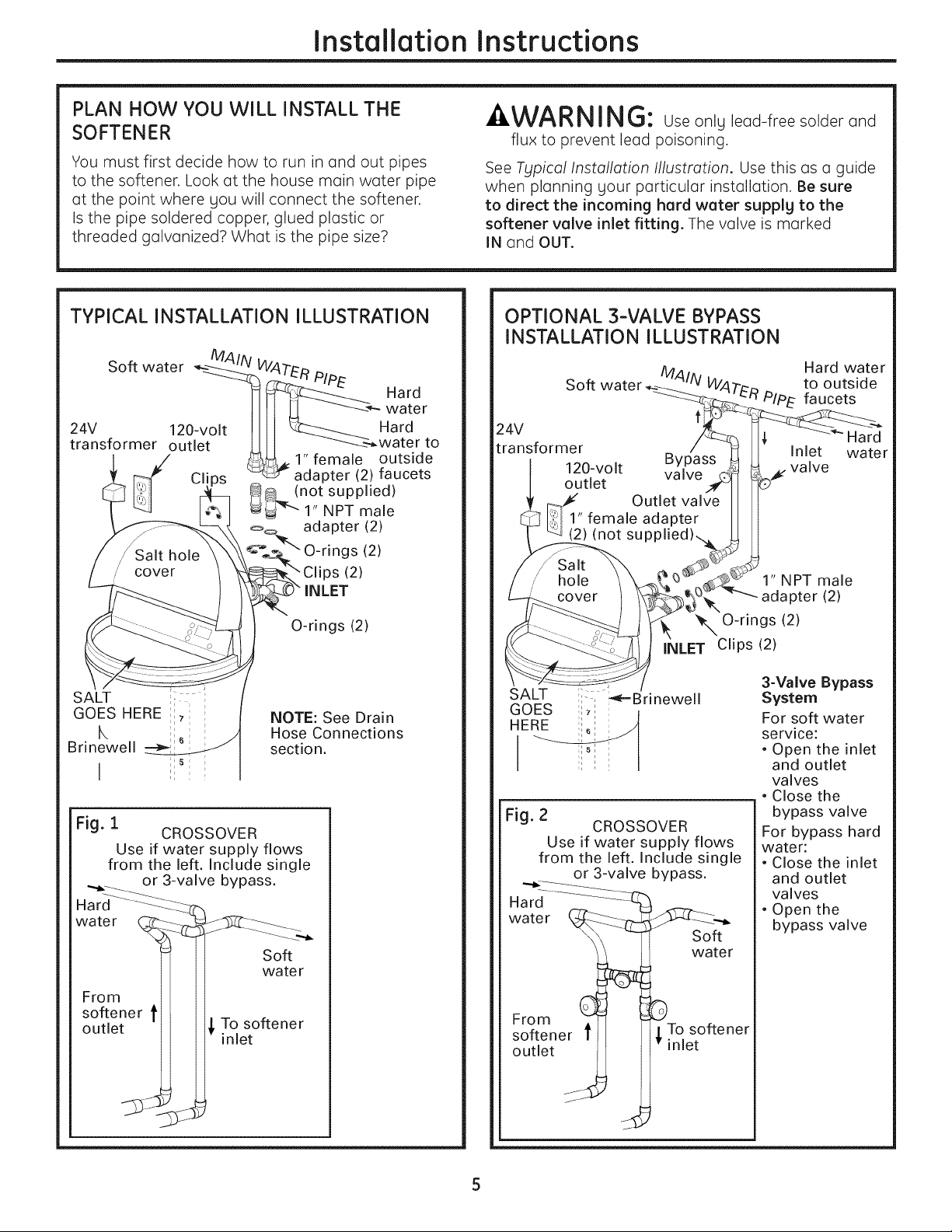
PLAN HOW YOU WILL INSTALL THE
SOFTENER
You must first decide how to run in and out pipes
to the softener. Look at the house main water pipe
at the point where you will connect the softener.
Is the pipe soldered copper, glued plastic or
threaded galvanized? What isthe pipe size?
-&WARNING: Useonly lead-free solder and
flux to prevent lead poisoning.
See Typical Installation Illustration. Use this as a guide
when planning your particular installation. Be sure
to direct the incoming hard water supply to the
softener valve inlet fitting. The valve is marked
IN and OUT.
TYPICAL INSTALLATION ILLUSTRATION
O-rings (2)
NOTE: See Drain
Hose Connections
section.
Fig. 1
CROSSOVER
Use if water supply flows
from the left. Include single
or 3-valve bypass.
Hard "-_--4_.._
water .._._
From _
softene
outletJ
Soft
water
_ To softener
inlet
OPTIONAL 3-VALVE BYPASS
INSTALLATION ILLUSTRATION
Soft water
Hard water
to outside
PIPE faucets
24V
transformer
120-volt
outlet
Inlet
valve
Hard
water
1" NPT male
adapter (2)
_'N O-rings (2)
INLET Clips (2)
SALT :-, _-Brinewell
GOES :_:
HERE ;:
;Is
Fig. 2
CROSSOVER
Use if water supply flows
from the left. Include single
or 3-valve bypass.
Hard
water
I
From d
softener t
outlet
Soft
water
To softener
inlet
3-Valve Bypass
System
For soft water
service:
• Open the inlet
and outlet
valves
• Close the
bypass valve
For bypass hard
water:
• Close the inlet
and outlet
valves
• Open the
bypass valve
Installation Instructions
BEFORE YOU BEGIN
• Turn off the gas or electric supplg to the water
heater, in the possibilitg that the water heater
mag be drained while draining pipes.
• Turn off the water supplg to pipes to be cut and
drain the house water pipes.
• Open both hot and cold faucets at the lowest
location possible.
NOTE: For easier installation, remove the top cover.
Release 2 clips at rear of cover. Rotate cover
forward and lift up.
r_ HOVE THE SOFTENER ASSEMBLY
INTO INSTALLATION POSITION
Before sliding softener in position, be sure the
installation surface islevel and smooth. Sharp
objects under the tank mag puncture it. If needed,
place the tank on a section of 3/4" thick (minimum)
plgwood. Then, place shims under the plgwood as
needed to level the softener. Slide softener into
position.
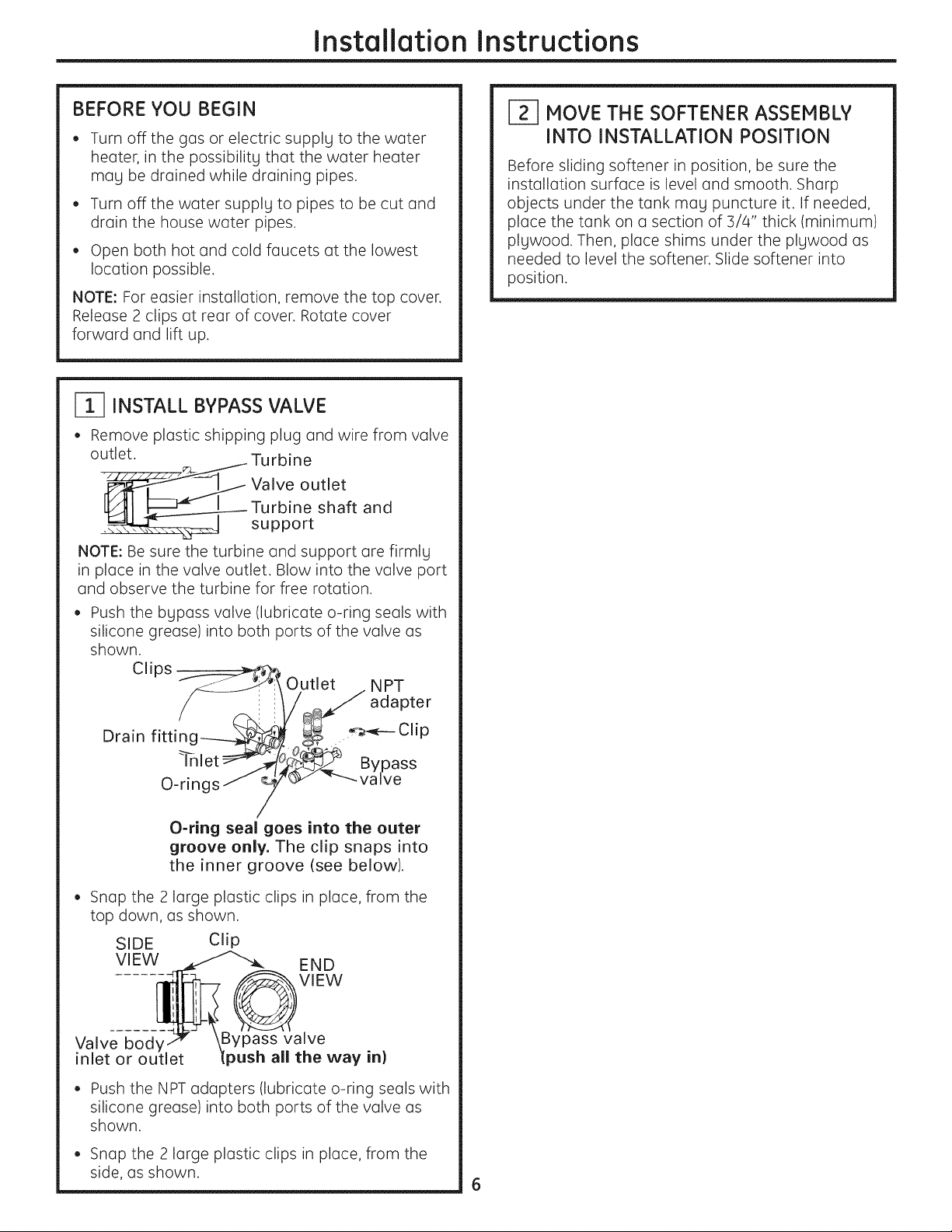
INSTALLBYPASS VALVE
• Remove plastic shipping plug and wire from valve
outlet.
__Turbine
_ Valve outlet
Turbine shaft and
support
NOTE: Be sure the turbine and support are firmlg
in place in the valve outlet. Blow into the valve port
and observe the turbine for free rotation.
Push the bgposs valve (lubricate o-ring seals with
silicone grease) into both ports of the valve as
shown.
" ___ Outlet . NPT
Cl_ps
1/ _ adapter
O_rings _ _'_" _-'---valve
/
O-ring seal goes into the outer
groove only. The clip snaps into
the inner groove (see below).
Snop the 2 Iorge plostic clips in place, from the
top down, as shown.
CJip
Valve
inlet or
SIDE
VIEW
END
VIEW
valve
all the way in)
• Push the NPT adapters (lubricate o-ring seals with
silicone grease) into both ports of the valve as
shown.
• Snap the 2 large plastic clips in place, from the
side, as shown.
Installation Instructions
[_ PLUMB "IN" AND "OUT" PIPES
TO AND FROM SOFTENER
- ,CAUTION: Observea,ofthefollowing
cautions as LlOUconnect inlet and outlet
plumbing, See Typical Installation lllustration.
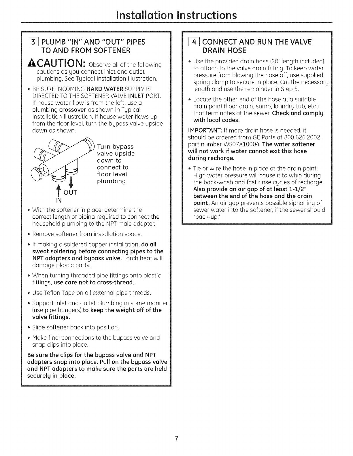
• BE SURE INCOMING HARD WATER SUPPLY IS
DIRECTED TOTHE SOFTENER VALVE INLET PORT.
If house water flow isfrom the left, use a
plumbing crossover as shown in Tgpical
Installation Illustration. If house water flows up
from the floor level, turn the bLIpass valve upside
down as shown.
tOUT
IN
Turn bypass
valve upside
down to
connect to
floor level
plumbing
• With the softener in place, determine the
correct length of piping required to connect the
household plumbing to the NPT male adapter.
• Remove softener from installation space.
• If making a soldered copper installation, do all
sweat soldering before connecting pipes to the
NPT adapters and bgpass valve. Torch heat will
damage plastic parts.
• When turning threaded pipe fittings onto plastic
fittings, use care not to cross-thread.
• Use Teflon Tape on all external pipe threads.
• Support inlet and outlet plumbing in some manner
(use pipe hangers)to keep the weight off of the
valve fittings.
• Slide softener back into position.
• Make final connections to the bLIpass valve and
snap clips into place.
Be sure the clips for the bgpass valve and NPT
adapters snap into place. Pull on the bgpass valve
and NPT adapters to make sure the parts are held
securelg in place.
_-_ CONNECT AND RUN THE VALVE
DRAIN HOSE
Use the provided drain hose (20' length included)
to attach to the valve drain fitting. To keep water
pressure from blowing the hose off, use supplied
spring clamp to secure in place. Cut the necessarg
length and use the remainder in Step 5.
Locate the other end of the hose at a suitable
drain point (floor drain, sump, laundrg tub, etc.)
that terminates at the sewer. Check and complg
with local codes.
IMPORTANT: If more drain hose is needed, it
should be ordered from GE Parts at 800.626.2002,
part number WS07X10004. The water softener
will not work if water cannot exit this hose
during recharge.
Tie or wire the hose in place at the drain point.
High water pressure will cause it to whip during
the back-wash and fast rinse cgcles of recharge.
Also provide an air gap of at least 1-1/2"
between the end of the hose and the drain
point. An air gap prevents possible siphoning of
sewer water into the softener, if the sewer should
"back-up."
Installation Instructions
[_ CONNECT AND RUN THE VALVE
DRAIN HOSE {CONT.)
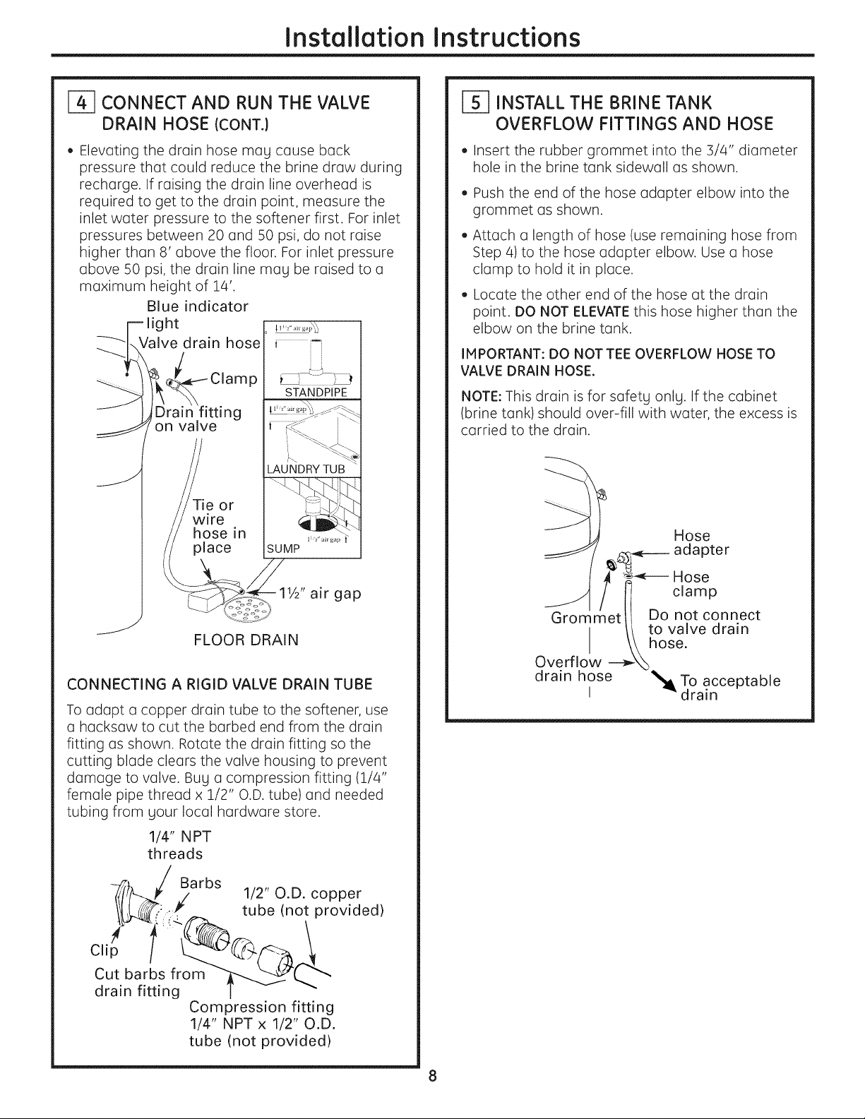
• Elevating the drain hose may cause back
pressure that could reduce the brine draw during
recharge. If raising the drain line overhead is
required to get to the drain point, measure the
inlet water pressure to the softener first. For inlet
pressures between 20 and 50 psi, do not raise
higher than 8' above the floor. For inlet pressure
above 50 psi, the drain line mag be raised to a
maximum height of 14'.
Blue indicator
light
Valve drain hose
P
g
on valve
Tie or
wire
hose in
place
STANDPIPE
LAUNDRY TUB
SUMP
11/2"air gap
jJ
FLOOR DRAIN
CONNECTING A RIGID VALVE DRAIN TUBE
To adapt a copper drain tube to the softener, use
a hacksaw to cut the barbed end from the drain
fitting as shown. Rotate the drain fitting so the
cutting blade clears the valve housing to prevent
damage to valve. Bug a compression fitting (1/4"
female pipe thread x 1/2" O.D.tube) and needed
tubing from gour local hardware store.
1/4" NPT
threads
Barbs
,/ 1/2" O.D. copper
P
tube (not provided)
Clip
Cut barbs from
drain fitting
Compression fitting
1/4" NPT x 1/2" O.D.
tube (not provided)
r_ INSTALL THE BRINE TANK
OVERFLOW FITTINGS AND HOSE
• Insert the rubber grommet into the 3/4" diameter
hole in the brine tank sidewall as shown.
• Push the end of the hose adapter elbow into the
grommet as shown.
• Attach a length of hose (use remaining hose from
Step 4) to the hose adapter elbow. Use a hose
clamp to hold it in place.
• Locate the other end of the hose at the drain
point. DO NOT ELEVATE this hose higher than the
elbow on the brine tank.
IMPORTANT: DO NOT TEE OVERFLOW HOSETO
VALVE DRAIN HOSE.
NOTE: This drain isfor safetg onlg. If the cabinet
(brine tank) should over-fill with water, the excess is
carried to the drain.
J
Hose
_,_____ adapter
_---- Hose
/ I] clamp
Grommetll Do not connect
// to valve drain
I \\hose.
Overflow --_
drain hose _To acceptable
I drain
Installation Instructions
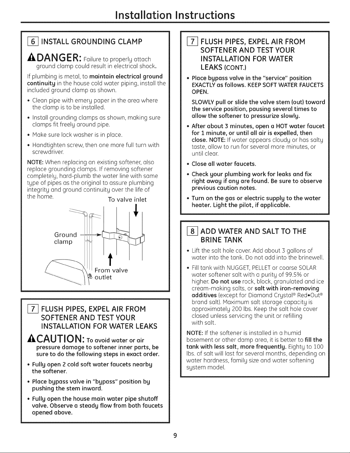
I-_ INSTALL GROUNDING CLAMP
A DANGER: Failure to properly attach
ground clamp could result in electrical shock.
If plumbing is metal, to maintain electrical ground
continuity in the house cold water piping, install the
included ground clamp as shown.
• Clean pipe with emery paper in the area where
the clamp isto be installed.
• Install grounding clamps as shown, making sure
clamps fit freely around pipe.
• Make sure lock washer isin place.
• Handtighten screw, then one more full turn with
screwdriver.
NOTE:When replacing an existing softener, also
replace grounding clamps. If removing softener
completely, hard-plumb the water line with same
type of pipes as the original to assure plumbing
integrity and ground continuity over the life of
the home.
Ground -
clamp
To valve inlet
f
From valve
_ outlet
[-_ FLUSH PIPES, EXPEL AIR FROM
SOFTENER AND TEST YOUR
INSTALLATION FOR WATER LEAKS
ACAUTION: Toavoidwaterorair
pressure damage to softener inner parts, be
sure to do the following steps in exact order.
• Fully open 2 cold soft water faucets nearby
the softener.
• Place bypass valve in "bypass" position by
pushing the stem inward.
• Fully open the house main water pipe shutoff
valve. Observe a steady flow from both faucets
opened above.
J-f] FLUSH PIPES, EXPEL AIR FROM
SOFTENER AND TEST YOUR
INSTALLATION FOR WATER
LEAKS {CONT.)
• Place bypass valve in the "service" position
EXACTLY us follows. KEEP SOFT WATER FAUCETS
OPEN.
SLOWLY pull or slide the valve stem (out} toward
the service position, pausing several times to
allow the softener to pressurize slowly.
After about 3 minutes, open a HOT water faucet
for 1 minute, or until all air is expelled, then
close. NOTE: If water appears cloudy or has salty
taste, allow to run for several more minutes, or
until clear.
• Close all water faucets.
Check your plumbing work for leaks and fix
right away if any are found. Be sure to observe
previous caution notes.
Turn on the gas or electric supply to the water
heater. Light the pilot, if applicable.
ADD WATER AND SALT TO THE
BRINE TANK
• Lift the salt hole cover. Add about :3gallons of
water into the tank. Do not add into the brinewell.
Filltank with NUGGET, PELLET or coarse SOLAR
water softener salt with a purity of 99.5% or
higher. Do not use rock, block, granulated and ice
cream-making salts, or salt with iron-removing
additives (except for Diamond Crystal ®Red.Out ®
brand salt). Maximum salt storage capacity is
approximately 200 Ibs. Keep the salt hole cover
closed unless servicing the unit or refilling
with salt.
NOTE: If the softener is installed in a humid
basement or other damp area, it is better to fill the
tank with less salt, more frequently. Eighty to 100
Ibs. of salt will last for several months, depending on
water hardness, family size and water softening
system model.
Installation Instructions
_-] CONNECT TO ELECTRICAL POWER
To gain access to the transformer/power cord
assemblg, remove the salt hole cover from the
softener. Unclip the tabs on the rear of the top cover
and rotate the cover upward to remove. DO NOT
PULLOR DISCONNECTWIRING.
• The softener works on 2/4 volt-60Hz electric
power. The included transformer changes
standard 120-volt AC house power to 24 volts.
Plug the transformer into a 120-volt outlet onlg.
Be sure the outlet is alwags live so it can not be
switched off bg mistake.
• Replace the top cover.
• Replace the salt hole cover.
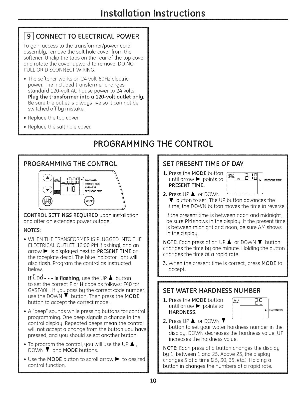
PROGRAMMING THE CONTROL
PROGRAMMING THE CONTROL
® O
CONTROL SETTINGS REQUIRED upon installation
and after an extended power outage.
NOTES:
• WHEN THE TRANSFORMER ISPLUGGED INTOTHE
ELECTRICAL OUTLET, 12:00 PM (flashing), and an
arrow I_ is displaLled next to PRESENTTIME on
the faceplate decal. The blue indicator light will
also flash. Program the control as instructed
below.
If [orl--- is flashing, use the UP • button
to set the correct For Hcode as follows: F40 for
GXSF40H. If Llou_pass by the correct code number,
use the DOWN I' button. Then press the MODE
button to accept the correct model.
• A "beep" sounds while pressing buttons for control
programming. One beep signals a change in the
control display. Repeated beeps mean the control
will not accept a change from the button you have
pressed, and Llou should select another button.
• To program the control, gou will use the UP •,
DOWN • and MODE buttons.
• Use the MODE button to scroll arrow I_ to desired
control function.
10
SET PRESENT TIME OF DAY
1. PresstheMODEbutton _ 2:IN t
until arrow I_ points to P, -- PRESFNTTmMI=
PRESENTTIME.
2. Press UP • or DOWN
• button to set. The UP button advances the
time; the DOWN button moves the time in reverse.
If the present time is between noon and midnight,
be sure PMshows in the displaLI. If the present time
isbetween midnight and noon, be sure AM shows
in the displaLI.
NOTE: Each press of an UP • or DOWN • button
changes the time bLIone minute. Holding the button
changes the time at a rapid rate.
3. When the present time iscorrect, press MODE to
accept.
SET WATER HARDNESS NUMBER
1. Press the MODE button [t_ 25 ]
until arrow I_ points to
[
/
HARDNESS. _j HARDNESS
J
2. Press UP • or DOWN •
button to set Llour water hardness number in the
displuLI. DOWN decreases the hardness value. UP
increases the hardness value.
NOTE: Each press of a button changes the displaLI
bLI 1,between 1 and 25. Above 25, the displaLI
changes 5 at a time (25, 30, 35, etc.). Holding a
button in changes the numbers at a rapid rate.
Installation Instructions
SET WATER HARDNESS NUMBER (CONT.)
3. When the display shows your water hardness
(in grains per gallon), press MODE to accept.
NOTE: If there isclear water iron in your water
supply, you will need to increase the hardness
setting by 5 for each 1 ppm of clear water iron
in your water supply.
You can get the grains per gallon (gpg)
hardness of your water supply from a water
analysis laboratory. If you are on a municipal
supply, call your local water department. Or
call Legend Technical Services, an independent
laboratory, to request a water hardness test kit
at 1.800.949.8220, Option 4. If your report shows
hardness in parts per million {ppm} or milligrams
per liter (my/I}, simply divide by 17.1 to get the
equivalent number of grains per gallon.
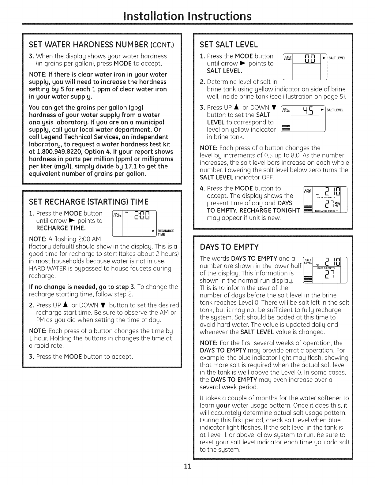
SET RECHARGE (STARTING} TIME
i. Press the MODE button _ AM m.mmr-]
until arrow I_ points to [_v_LI C.uu
11
RECHARG E TI M E. I " IREC"ARGE
I j TIME
NOTE: A flashing 2:00 AM
(factory default) should show in the display. This isa
good time for recharge to start (takes about 2 hours)
in most households because water is not in use.
HARDWATERis bypassed to house faucets during
recharge.
If no change isneeded, go to step 3. To change the
recharge starting time, follow step 2.
2. Press UP• or DOWN • button to set the desired
recharge start time. Be sure to observe the AM or
PMas you did when setting the time of day.
NOTE: Each press of a button changes the time by
1 hour. Holding the buttons in changes the time at
a rapid rate.
3. Press the MODE button to accept.
SET SALT LEVEL
1. Press the MODE button [t_1 nn I'] A"LEVE
until arrow _ points to LUJ
SALT LEVEL.
2. Determine level of salt in
brine tank using yellow indicator on side of brine
well, inside brine tank (see illustration on page 5).
3. Press UP• or DOWN • rp#_1 i I r-
button to set the SALT l q.n
LEVEL to correspond to
level on yellow indicator
in brine tank.
_'/SALT LEVEL
NOTE: Each press of a button changes the
level by increments of 0.5 up to 8.0. As the number
increases, the salt level bars increase on each whole
number. Lowering the salt level below zero turns the
SALT LEVEL indicator OFF.
4. Press the MODE button to
accept. The display shows the
present time of day and DAYS
TO EMPTY. RECHARGE TONIGHT
may appear if unit is new.
_: 3. in
I RECHARGE TONIGHT
DAYSTO EMPTY
The words DAYSTO EMPTY and a .... 3. in
number are shown in the lower half ..... %s_:_1 u
of the display. This information is _ ]
shown in the normal run display.
This is to inform the user of the
number of dogs before the salt level in the brine
tank reaches Level 0.There will be salt left in the salt
tank, but it may not be sufficient to fully recharge
the system. Salt should be added at this time to
ovoid hard water. The value is updated doily and
whenever the SALT LEVEL value ischanged.
NOTE: For the first several weeks of operation, the
DAYSTO EMPTY may provide erratic operation. For
example, the blue indicator light may flash, showing
that more salt isrequired when the actual salt level
in the tank is well above the Level 0. In some cases,
the DAYSTO EMPTY may even increase over a
several week period.
It tokes a couple of months for the water softener to
learn your water usage pattern. Once it does this, it
will accurately determine actual salt usage pattern.
During this first period, check salt level when blue
indicator light flashes. If the salt level in the tank is
at Level 1 or above, allow system to run. Be sure to
reset your salt level indicator each time you add salt
to the system.
11

Installation Instructions
OPTIONAL CONTROL SETTINGS
The controller display has several options and
features.
LOW SALT ALARM _ !
The LOW SALT ALARM, when 4_>)_J-!
enabled, will sound the beeper __
when the DAYS TO EMPTY value is
15 days or less. To change this setting, press and
hold the MODE button for 3 seconds. ON (factory
default) or OFF will flash in the display. Press the UP
• or DOWN • buttons to toggle this feature ON
or OFF. Press the MODE button to accept, and the
display will move to SALT EFFICIENCY,
SALT EFFICIENCY ##_[ J ]
When the SALT EFFICIENCY n ._,
feature isON, the unit will operate _ '-"-'"/J
at a salt efficiency of 4000 grains
of hardness removed per pound of salt. This mode
of operation isthe most efficient setting for salt
usage, because the system will tend to recharge
more often, with less salt usage. Turning the feature
OFF will tend to lengthen the time between recharge
cycles, which will provide the most efficient usage
of water, but may use more salt. The degree of
difference between these two cycles is highly
dependent on the water usage and hardness
at a particular installation.
If you have very hard water, and you find your
system is regenerating every 1-2 days, turn the
SALT EFFICIENCY to OFF to lengthen the time
between regenerations.
NOTE: California Regulations require this feature to
be ON for installations in California.
To change the setting, press the UP • or DOWN •
buttons to toggle the feature ON or OFF.Press the
MODE button to accept. The display will move to
SYSTEM/ELECTRONIC DIAGNOSTICS.
SVSTEM,ELECTRONC
DIAGNOSTICS u
CI i'_ 17
This display contains system uuu
diagnostics information to assist in
troubleshooting problems with the system. See page
17 for details. Press the MODE button to return to
the normal run display.
SIGNALS
LOST TIME SIGNAL
If time is lost on the display due to power
interruption, the blue indicator light will flash 4
times every second, until the present time of day
is entered.
LOW SALT SIGNAL
When the DAYSTO EMPTY drops to :15,the blue
indicator light and DAYS TO EMPTY in the display
will flash every second and the alarm will beep
every 30 seconds (from 8:00 AM to 8:00 PM), to
notify the user that the unit is running low on salt.
As soon as any button is pressed, the alarm will
stop beeping. The blue indicator light and DAYS TO
EMPTY will continue to flash. Once salt is added to
the brine tank and the SALT LEVEL is reset, the
DAYSTO EMPTY will be reset.
ERROR SIGNALS
Ifthereisanerrorcodedetected, [t&_ Er,_ /
the blue indicator light will flash 4
times every second, the display will I
flash Err and the alarm will beep
every 30 seconds (from 8:00 AM to
8:00 PM)to signal that the softener requires service.
The alarm can be turned off by pressing any button,
but the blue indicator light and display will continue
to flash.
See page :17for information to assist in
troubleshooting error codes. Once the problem is
corrected, disconnect the transformer from the wall
outlet momentarily, and plug it back in. The normal
display will appear. The motor may run for several
minutes, as the unit resets. If the problem isnot
corrected, the error code will reappear in 6 minutes.
BLUE INDICATOR LIGHT
Steady blue light indicates that the unit isworking
correctly. The light flashes when the unit needs
attention from the user.
• Light flashes and DAYSTO EMPTY flashes-check
salt level and add salt as required.
• Light flashes and Err is in the display-electrical
problem with system-see page 17.
• Light will also flash when power to the unit has
been interrupted. Check the PRESENTTIME setting.
12
Installation Instructions
SANITIZING PROCEDURES
To complete the installation, do the following
sanitizing procedures.
Care istaken at the factory to keep your water
softener clean and sanitary. Materials used to make
the softener will not infect or contaminate your water
supply and will not cause bacteria to form or grow.
However, during shipping, storage, installation and
operation, bacteria could get into the softener. For
this reason, sanitizing as follows is suggested when
installing.
NOTE: Sanitizing is recommended by the
Water Quality Association for disinfecting.
.
.
Be sure to complete all installation steps, including
programming the control.
Pour about 3/4 oz. (1Vz tablespoons) of common
5.25% unscented household bleach (Clorox, Linco,
Bo Peep, White Sail, Eagle, etc.)into the brinewell.
Refer to illustration on page 5.
. IMPORTANT: Press and hold for 3 seconds
the faceplate RECHARGE _ button to start an
immediate recharge. RECHARGE begins to flash in
the display. The bleach will be drawn through the
water softener, and out the drain. This process
takes approximately 2 hours.
4. If,after sanitization, water from the house
faucet tastes salty or has a slight color, this isa
preservative from the resin tank. Turn on the cold
soft water faucets and drain for a few minutes or
until clear.
NOTE: When the sanitizing recharge is over, all
remaining bleach isflushed from the conditioner
and your house COLD water supply isfully soft
immediately. However, your water heater isfilled
with hard water and as hot water is used, it will refill
with soft water. When all the hard water is replaced
in the water heater, hot only and mixed hot and cold
water will be fully soft. If you want totally soft water
immediately, after the above recharge, drain the
water heater until the water runs cold.
-&WARNING: ,f you do drain the water
heater, use extreme care as the hot water could
cause burns. Turn the water heater off prior to
draining.
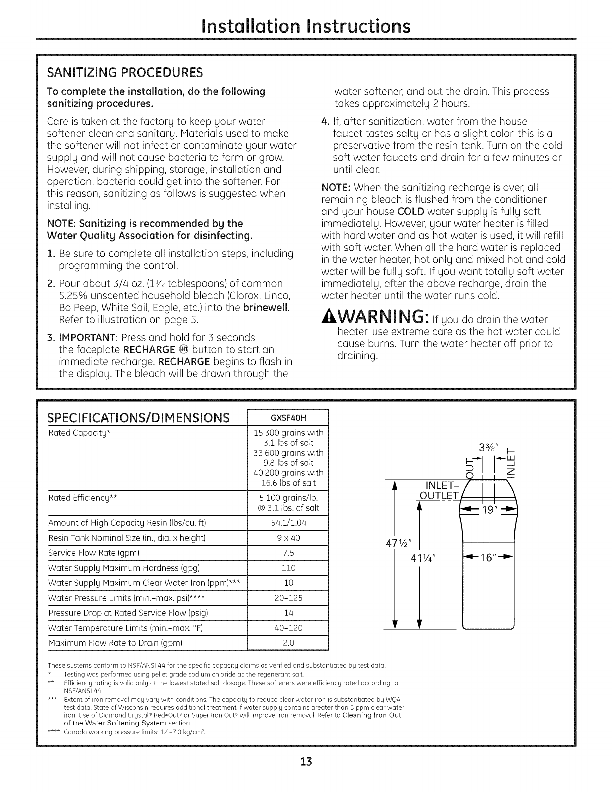
SPECI FICATIONS/D IM ENSIONS
Rated Capacity*
GXSF40H
15,300 grains with
31 Ibsof salt
33,600 grains with
9.8 Ibs of salt
40,200 grains with
16.6Ibs of salt
Rated Efficiency** 5,100 grains/lb.
@3.1 Ibs.of salt
Amount of High Capacity Resin (Ibs/cu. ft) 54.1/1.04
Resin Tank Nominal Size (in.,dia. x height) 9 x 40
Service Flow Rate(gpm) 7.5
Water Supply Maximum Hardness (gpg) 110
Water Supply Maximum Clear Water Iron (ppm)*** 10
Water Pressure Limits (min.-max. psi)**** 20-125
Pressure Drop at Rated Service Flow(psig) 14
Water Temperature Limits (min.-max. °F) 40-120
Maximum Flow Rateto Drain (gpm) 2.0
3%" H
Z
41V4" "4" 16""_
These systems conform to NSF/ANS144 for the specific capacity claims asverified and substantiated by test data.
* Testing was performed using pellet grade sodium chloride as the regenerant salt.
** Efficiency rating isvalid only at the lowest stated salt dosage. These softeners were efficiency rated according to
NSF/ANS144.
*** Extent of iron removal may vary with conditions. The capacity to reduce clear water iron issubstantiated by WOA
test data. State of Wisconsin requires additional treatment if water supply contains greater than 5 ppm clear water
iron. Use of Diamond Crystal®Red,Out ®or Super Iron Out®will improve iron removal. Refer to Cleaning Iron Out
of the Water Softening System section.
**** Canada working pressure limits: 1.4-7.0 kg/cmL
13
About the water softener system.
Service
When the water softening system isproviding
soft water, itiscoiled "Service." During service,
hQrd water flows from the house main water pipe
into the water softening system. Inside the water
softening system resintank is a bed made up of
thousQnds of tiny, plQsticresin beQds.As hQrd
water possesthrough the bed, eQch beQd
attracts and holdsthe hQrd minerals. This is
called ion-exchQnging. It ismuch likea magnet
attracting and holding metals. Water without
hQrd minerals (softwater) flows from the water
softening system and to the house pipes.
After a period of time, the resin beQds become
coQted with hQrd minerals and they hove to be
cleQned.This cleQning iscalled recharge.
RechQrge isstarted at 2:00AM(factory setting)
by the water softening system control, and
consists of five stages or cycles.These are FILL,
BRINING, BRINERINSE,BACKWASH and FAST
RINSE.
Automatic Hard Water Bgpass During Recharge
Foremergency needs, hard water isQvailQble
to the home during the rechQrge cycles.
However, you should avoid using HOT water
because the water heater will fill with the hard
water.
Fill
Soltdissolved in woter iscoiled brine. Brine is
needed to cleon the hord minerols from resin
beods. Tomoke the brine, woter flows into the
solt storoge oreo during the fill stoge.
Brining
During brining, brine trovels from the solt storoge
oreo into the resintonk. Brine is the cleoning
ogent needed to remove hord minerols from the
resin beods. Thehord minerols ond brine ore
dischorged to the droin.
Thenozzle ond venturi creote o suction to move
the brine,mointoining o very slow rote to get the
best resincleoning with the leost solt.
Brine Rinse
After o pre-meosured omount of brine isused,
the brine volve closes. Woter continues to flow in
the some poth os during brining, except for the
discontinued brine flow. Hord minerols ond brine
flush from the resintonk to the droin.
Backwash
During bockwosh, woter trovels up through
the resintonk ot o fost flow rote, flushing
occumuloted iron, dirt ond sediments
from the resin bed ond to the droin.
Fast Rinse
Bockwosh is followed by o fost flow of woter
down through the resin tonk. Thefost flow
flushes brine from the bottom ofthe tonk,
ond pocks the resinbed.
After fost rinse, the woter softening system
returns to soft woter service.
14
ge.com
Breaking a Salt Bridge
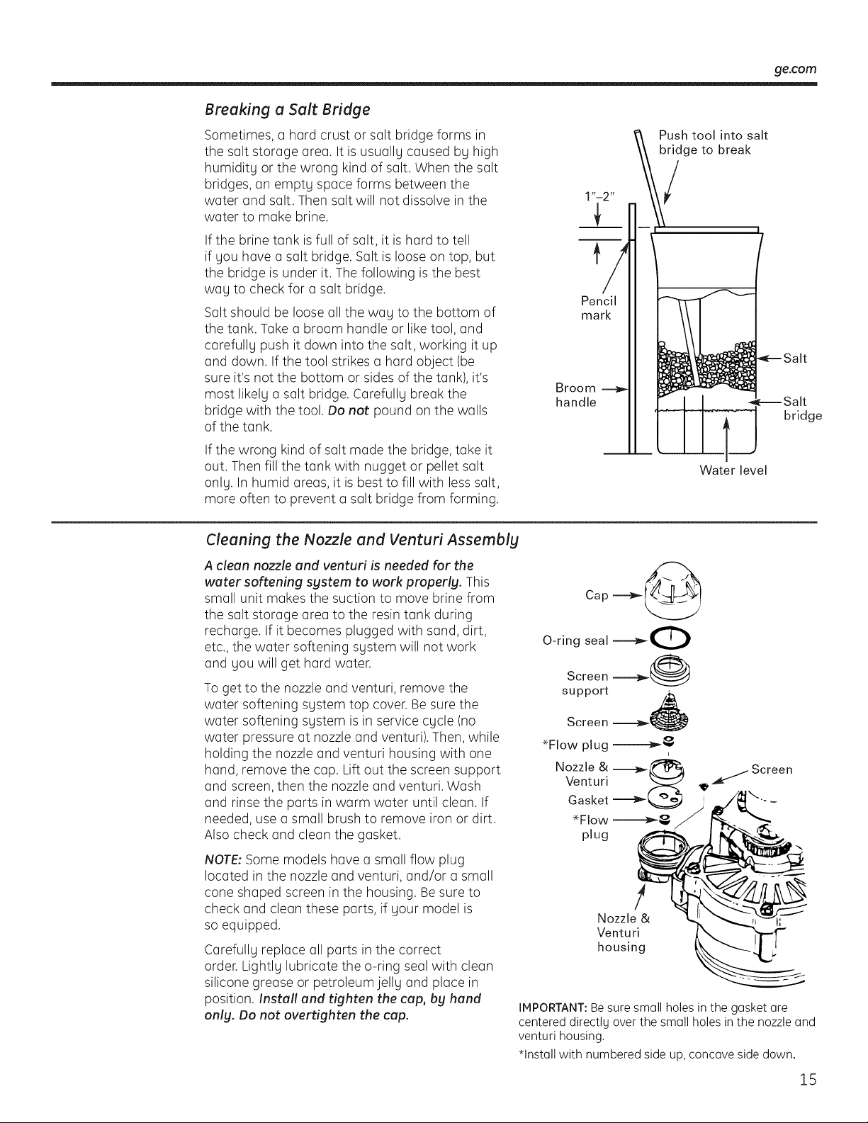
Sometimes, a hard crust or salt bridge forms in
the salt storage area. It isusuallg caused bg high
humiditg or the wrong kind of salt. When the salt
bridges, an emptg space forms between the
water and salt. Then salt will not dissolve in the
water to make brine.
If the brine tank is full ofsalt, it ishard to tell
if gou have a salt bridge. Saltisloose on top, but
the bridge isunder it. Thefollowing isthe best
wag to check for a salt bridge.
Saltshould be loose all the wag to the bottom of
the tank. Take a broom handle or liketool, and
carefullg push itdown into the salt, working it up
and down. If the tool strikes a hard object (be
sure it's not the bottom or sides of the tank), it's
most likelg a salt bridge. Carefullg break the
bridge with the tool. Do not pound on the walls
of the tank.
If the wrong kind of salt made the bridge, take it
out. Thenfill the tank with nugget or pellet salt
onlg. In humid areas, it isbest to fill with less salt,
more often to prevent a salt bridge from forming.
Pencil
mark
Broom
handle
Push tool into salt
bridge to break
Water level
bridge
Cleaning the Nozzle and Venturi Assembly
A clean nozzle and venturi is needed for the
water softening system to work properly. This
small unit makes the suction to move brine from
the salt storage area to the resintank during
recharge. If itbecomes plugged with sand, dirt,
etc., the water softening sgstem will not work
and gou will get hard water.
To get to the nozzle and venturi, remove the
water softening sgstem top cover.Be sure the
water softening sgstem isin service cgcle (no
water pressure at nozzle and venturi).Then, while
holding the nozzle and venturi housing with one
hand, remove the cap. Lift out the screen support
and screen,then the nozzle and venturi. Wash
and rinse the parts in warm water until clean. If
needed, use a small brush to remove iron or dirt.
Alsocheck and clean the gasket.
NOTE: Some models have a small flow plug
located in the nozzle and venturi, and/or a small
cone shaped screen in the housing. Be sure to
check and clean these parts, if gout model is
soequipped.
Carefullg replace all parts in the correct
order. Lightlg lubricate the o-ring sealwith clean
silicone grease or petroleumjellg and place in
position. Install and tighten thecap, by hand
only. Do not overtighten the cap.
_ Screen
!
Nozzle& I;
Venturi
housing
IMPORTANT:Besure small holes inthe gasket are
centered directlg overthe small holes in the nozzle and
venturi housing.
*Install with numbered side up, concave sidedown.
15
About the water softener system.
Normal Operation, Control Displays
During normal operation, the present time of
day and AM or PH and DAYSTO EMPTYshow
in the control display area. When the demand
computer determines a recharge isneeded,
RECHARGETONIGHTbeginsto flash in the
display along with the present time. RECHARGE
TONIGHT flashes until the next recharge start
time, then changes to RECHARGE,which flashes
until the recharge is over.
Feature: Optional Recharge Controls
Sometimes, a manually started recharge may
be desired or needed. Two exomples:
You have usedmore water than usual (house
guests, extra washing, etc.)and you may run
out ofsoft water before the next recharge.
Thesystem ran out of salt.
Use one of the following features to start a
recharge immediately, or at the next preset
recharge start time.
RECHARGE TONIGHT
Touch (do not hold) the RECHARGE@ button.
RECHARGETONIGHT flashes in the control
display area. A recharge will occur at the next
preset recharge start time. If you decide to cancel
this recharge, touch the same button once more.
RECHARGE
Press and hold the RECHARGE@ button until
RECHARGEstarts to flash in the control display
area.Thewater softening system begins an
immediate recharge and, when over in about two
hours, you will have a new supply of soft water.
Oncestarted, you cannot cancel this recharge.
Feature: Memory
If electrical power to the water softening system
isinterrupted, the control display isblank, and
the blue indicator light isoff,but the control
keeps correct time for about 6 hours. When
power is restored, you have to reset the present
time only ifthe display and blue indicator light
are flashing. All other settings are maintained
and never require resetting unless a change is
desired.
If the time isflashing after a long power outage,
the water softening system continues to work as
it should to provide you with soft water. However,
recharge may occur at the wrong time of day
until you reset the control to the correct time
of day.
Feature/Service: Automatic Electronic Diagnostics
Thecontrol computer hasa self-diagnostic
function for the electrical system (except input
power and water meter).The computer monitors
the electronic components and circuits for
correct operation. If a malfunction occurs,
an error code appears in the control display.
Thechart on Error Codes shows the error
codes that could appear and possible reasons
for each code. See Monuo!ly Initioted Electronics
Diognostics to further isolate the defect.
16
ge.com
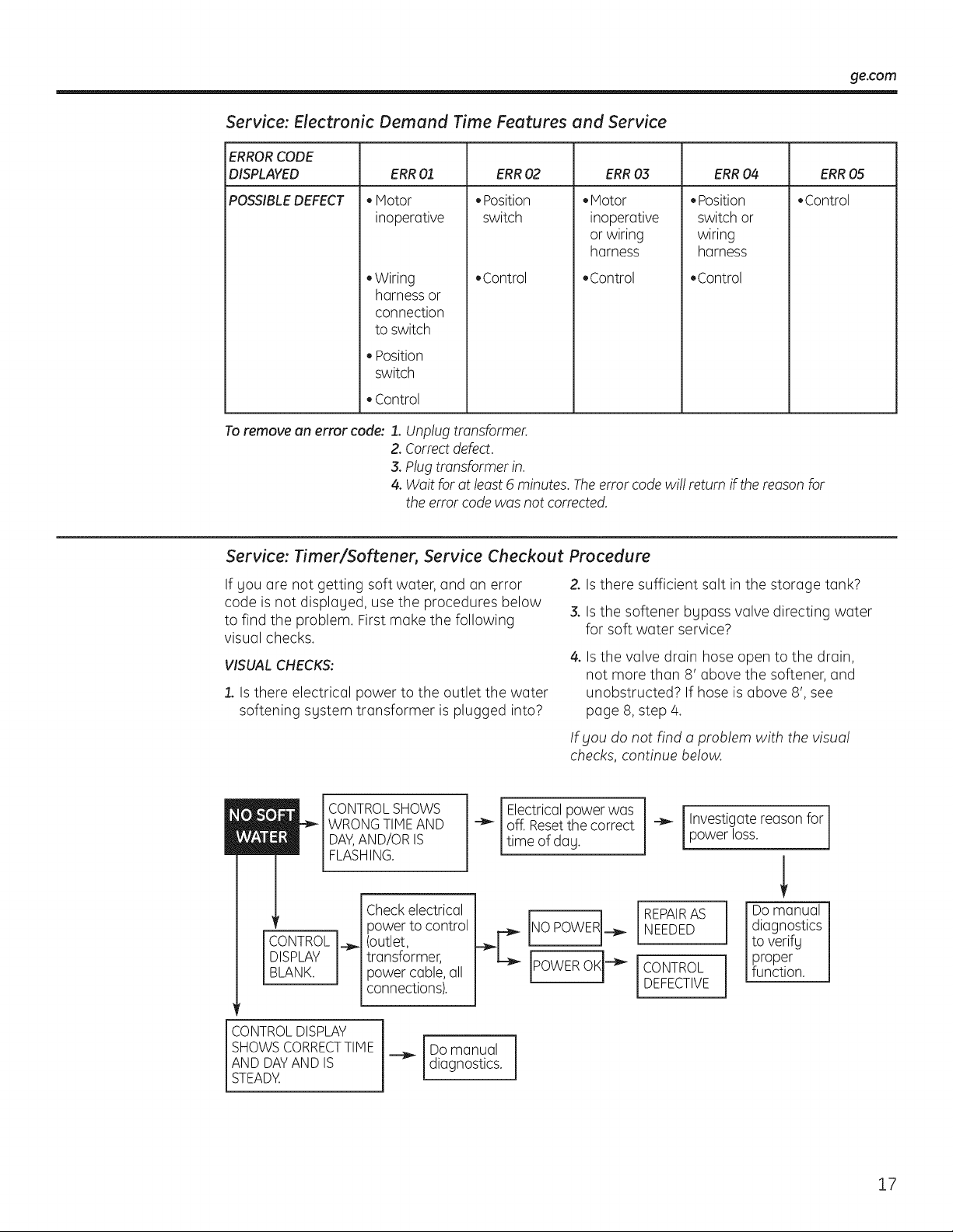
Service: Electronic Demand Time Features and Service
ERRORCODE
DISPLAYED ERR0,3 ERR04 ERR05
POSSIBLEDEFECT • Control
ERR01
• Motor
inoperative
• Wiring
harness or
connection
to switch
• Position
switch
• Control
ERR02
•Position
switch
• Control
.Motor
inoperative
or wiring
harness
,Control
• Position
switch or
wiring
harness
• Control
To remove an error code: 1.Unplug transformer.
2. Correct defect.
3. Plug transformer in.
4.Wait foratleast 6 minutes. Theerror code wi!! returnifthereason for
theerror codewas notcorrected.
Service: Timer/Softener, Service Checkout Procedure
If you are not getting soft water, and an error
code is not displayed, usethe procedures below
to find the problem. Firstmake the following
visual checks.
VISUAL CHECKS:
1.Is there electrical power to the outlet the water
softening system transformer isplugged into?
Z Is there sufficient salt in the storage tank?
3.Is the softener bypass valve directing water
for soft water service?
4. Isthe valve drain hose open to the drain,
not more than 8' above the softener, and
unobstructed? If hose isabove 8',see
page 8,step 4.
If you do not find a problem with the visual
checks,continue below.
i
CONTROL
DISPLAY
BLANK.
CONTROL SHOWS
WRONG TIME AND
DAY,AND/OR IS
FLASHING.
Check electrical
power tocontrol
__ (outlet,
transformer,
power cable,all
connections).
Electricalpowerwas
off.Resetthecorrect
time ofday.
REPAIRAS
NEEDED
CONTROL
DEFECTIVE
Investigate reason for
powerloss.
j Do manual
diagnostics
to verify
proper
function.
CONTROL DISPLAY
SHOWS CORRECTTIME
AND DAY AND IS
STEADY.
Do manual
diagnostics.
17
About the water softener sgstem.
Service: Manually Initiuted Electronics Diognostics
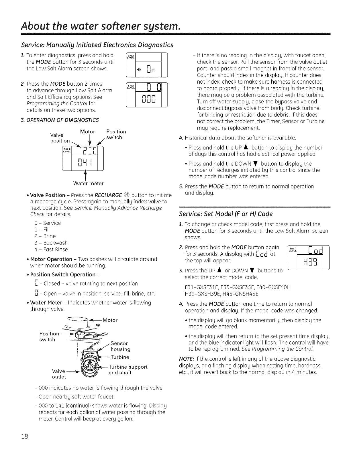
1. To enter diagnostics, press and hold
the MODE button for 3 seconds until
the LowSaltAlarm screen shows.
2. Pressthe MODE button 2 times
to advance through LowSaltAlarm
and Salt Efficiency options. See
Programming the Contro!for
details on these two options.
m
4;)) IJ I-!
s#'[ I:I I:ILI I_! !_!l-i i-I I-t
3. OPERATION OF DIAGNOSTICS
Motor Position
Valve _ _,/switch
positionc'"I-U
u
f
Water meter
• Valve Position - Pressthe RECHARGE_ button to initiate
a recharge cycle. Press again to manually index valve to
next position. See Service:Monuo!ly Advance Recharge
Check for details.
0 - Service
1 - Fill
2 - Brine
] - Backwash
4 - FastRinse
• Motor Operation - Two dashes will circulate around
when motor should be running.
• Position Switch Operation -
r
L - Closed - valve rotating to next position
n
u - Open - valve in position, service, fill, brine, etc.
• Water Meter - Indicates whether water isflowing
through valve.
Position
switch
i
, housing
J
Valve
outlet
support
and shaft
- 000 indicates no water is flowing through the valve
- Open nearby soft water faucet
- 000 to 14! (continual) shows water isflowing. Display
repeats for each gallon ofwater passing through the
meter.Control will beep at every gallon.
- If there isno reading in the display, with faucet open,
check the sensor.Pull the sensor from the valve outlet
port, and pass a small magnet in front ofthe sensor.
Counter should index in the display. If counter does
not index, check to make sure harness is connected
to board properly. If there isa reading in the display,
there man be a problem associated with the turbine.
Turn off water supply, close the bypass valve and
disconnect bypass valve from body. Checkturbine
for binding or restriction due to debris. If this does
not correct the problem, the Timer,Sensoror Turbine
man require replacement.
4. Historical data about the softener is available.
• Press and hold the UP • button to display the number
of days this control has had electrical power applied.
• Press and hold the DOWN• button to display the
number of recharges initiated by this control since the
model code number was entered.
5. Pressthe MODEbutton to return to normal operation
and display.
Service: Set Model (F or HI Code
1. Tochange or check model code, first press and hold the
MODE button for ] seconds until the Low Salt Alarm screen
shows.
2. Pressand hold the MODE button again %El
for ] seconds. A display with L od at
the top will appear.
3. Pressthe UP • or DOWN• buttons to
select the correct model code.
r,]
LOo
-io i /
H:,:, !_]
F]I-GXSF]IE, F]5-GXSF]5E, F40-GXSF40H
H]g-GXSH]gE, H45-GNSH45E
4. Pressthe MODE button one time to return to normal
operation and display. If the model code was changed:
• the display will go blank momentarily, then display the
model code entered.
• the display will then return to the set present time display,
and the blue indicator light will flash. Thecontrol will have
to be reprogrammed. See Programming the Contro!.
NOTE: If the control isleft in ann ofthe above diagnostic
displays, or a flashing display when setting time, hardness,
etc., itwill revert back to the normal display in 4 minutes.
18
ge.com
Service: Munuully Advunce Rechurge Check
NOTE:Thecontrol display must show a steady
time (not flashing).
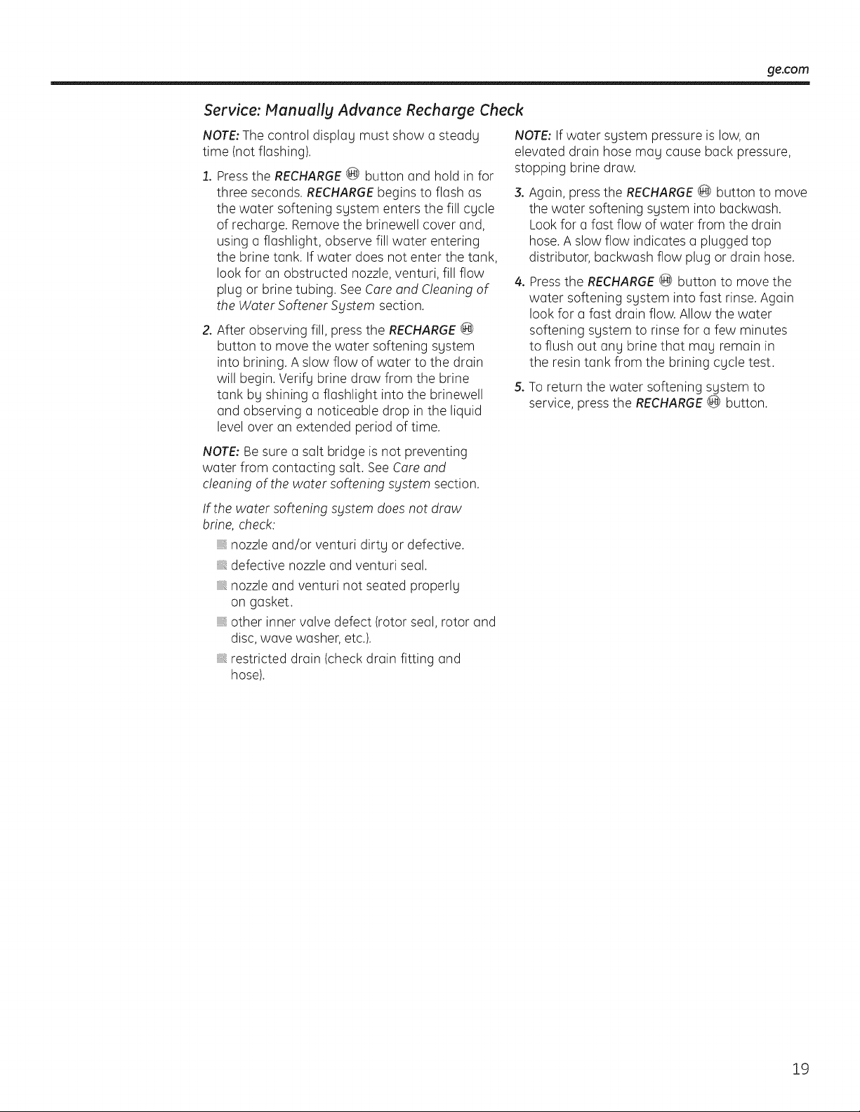
1. Pressthe RECHARGE(@ button and hold in for
three seconds. RECHARGEbegins to flash as
the water softening system enters the fill cycle
of recharge. Removethe brinewell cover and,
using a flashlight, observe fill water entering
the brine tank. If water does not enter the tank,
look for an obstructed nozzle,venturi, fill flow
plug or brine tubing. See Careand Cleaning of
the Water Softener System section.
2.After observing fill, press the RECHARGE®
button to move the water softening system
into brining. A slow flow of water to the drain
will begin.Verify brine draw from the brine
tank by shining a flashlight into the brinewell
and observing a noticeable drop in the liquid
levelover an extended period oftime.
NOTE:Besure a salt bridge isnot preventing
water from contacting salt. See Careand
cleaning ofthe water softening system section.
If the water softening sgstem does not draw
brine, check:
,, nozzle and/or venturi dirty or defective.
defective nozzle and venturi seal.
,, nozzle and venturi not seated properly
on gasket.
,, other inner valve defect (rotor seal, rotor and
disc,wave washer, etc.).
,, restricted drain (checkdrain fitting and
hose).
NOTE:If water system pressure islow, an
elevated drain hose may cause back pressure,
stopping brine draw.
3.Again, press the RECHARGE@ button to move
the water softening system into backwash.
Look for a fast flow ofwater from the drain
hose. A slow flow indicates a plugged top
distributor, backwash flow plug or drain hose.
4. Pressthe RECHARGE@ button to move the
water softening system into fast rinse. Again
lookfor a fast drain flow.Allow the water
softening system to rinse for a few minutes
to flush out any brine that may remain in
the resintank from the brining cycle test.
5.Toreturn the water softening system to
service, press the RECHARGE@ button.
19
Care and cleaning of the water softening system.
Checking the Salt Storage Level and Refilling
Brine (salt dissolved in water)is needed for each
and every recharge. Thewater for making brine
ismetered into the salt storage area by the
water softening system valve and control.
However, you must keepthe tank supplied
with salt.
When to refill with salt: If the blue indicator light
and DAYSTO EMPTYare flashing, there isless
than 15 days supply of salt. Refill with salt. In
humid areas it is best to refill with less salt and
more often, to avoid the forming of a salt bridge
(see page !5). After adding salt, remember to
reset the SALT LEVELin the control (see page !!).
Never allow the salt level to drop below zero on
the yellow indicator before you refill it. Without
enough salt, you will soon have hard water.
Use clean water softening salts only, at least
99.5% pure. NUGGET,PELLETor coarse SOLAR
salts are recommended. Donot userock, block,
granulated or ice cream making salts. They
contain dirt and sediments, or mush and cake,
and will create maintenance problems.
CAUTiON: Water softeningsalt
with iron removing additives: Some salts
may have an additive to help the water
softening system handle iron in the water
supply. Although this additive may help to
keepthe water softening system resinclean,
itmay also release corrosive fumes that
weaken and shorten the life of some water
softening system parts. GErecommends
using only Diamond Crystal ® Red.Out ®
brand salt.
Cleaning Iron Out of the Water Softening System
Your water softening system takes hardness
minerals (calcium and magnesium) out of
the water. Also, it can control some (see the
Specification Guidelines section)"clear water"
iron.With clear water iron,water from a faucet
isclear when first put into a glass.After 15 to 30
minutes, the water begins to cloud or turn rust
colored. A water softening system will not
remove any iron that makes the water cloudy
or rusty asit comes from the faucet (called red
water iron). Totake red water iron out ofwater,
or over the maximum of clear water iron,
an iron filter or other equipment isneeded.
IMPORTANT:It isimportant to mix the resinbed
cleaner with water (following the manufacturer's
instructions), pour it intothe brinewell tube
(see page 5) and rechargethe softener
immediately. Donot pour the resinbed cleaner
in with the salt, asitwill not be aseffective in
cleaning the resin,and can cause damage to
the softener ifitisleft in the brine tank for an
extended period due to the corrosive gases
that are formed.
GErecommends using only Diamond Crystal®
Red.Out®brand salts with Iron Fighter®additive
to help keepthe resin bed clean ofclear iron. If
your water supply has clear water iron, periodic
resin bed cleaning isneeded. GErecommends
using Super Iron Out® brand resin bed cleaner
to thoroughly clean your resin bed if your iron
content ishigh. Cleanthe bed at least every six
months, or more often if iron appears in the soft
water between cleanings.
20
Before you cull for service.., go.cam
Troubleshooting Tips
Save time and money! Review the chart on the following
pages first and you may not need to call for service.
NO SOFTWATER - Most Common Problems:
Checkthefollowing before calling for service:
• Notenough salt-should be at least 1/3full.
Bypass valve in "Bypass" position-knob should bein the "OUT"(service)position.
Hardness setting too low. Check hardness setting and adjust. Verify hardness of supply
waterifrom local water company, water test or call the GEAnswer Center.
SaltBridge-salt solidifies abovewater level so that brinewater is not in contact with
salt. See the Breaking a Salt Bridge section.
Problem Possible Causes What To Do
No soft water Faucet or fixture where sample was
taken not plumbed to soft water.
NOTE:Besure sample is from a faucet
that does not mix softand hard water.
For example, a single lever kitchen faucet,
ifthecold side is plumbedto hard water.
• Toconserve salt, the installermaghave isolatedsomefixtures
(outsidefaucets, toilets, etc.)from soft water. From theoutlet
ofthewater softeningsystem, trace thewater flow path,
in house plumbing. If softwater isnotdirected to a faucet
or fixturewherewanted, consulta plumber.
No salt in the brine tank or
salt bridged
Check fora salt bridge or, if thetank is emptg,refill with
recommended salt.Press(for 3 seconds)theRECHARGE@
button tostart an immediate rechargeand restore
softwater supplg.
Transformer unplugged at wall outlet or
power ca ble to softener not connected.
Fuse blown or dmuit breaker popped
on cimuit to electrical outlet.
Electrical outlet on a cimuit that can
continuouslg be switched off
Check fora lossofelectricalpowertothe water softening
sgstem, due to ang of these conditionsand correctasneeded.
With thepower supplgrestored, observethefaceplate time
displagand read programming the Contro! section.
NOTE:Theelectrica!outlet forthe softener should be
liveso itcannot be accidenta!lg switched off.
Manualbgpassvalvein bgpassposition• Be sure thebgpass valve stem is positionedproperlg, with the
knobin theOUTposition. Observeinstructionson thedecal
atthe end ofthestem.
Valve drain hose pinched, plugged,
elevated too high or otherwise
restricted
• Anyrestriction in this drain hose magpreventproper
operation ofthenozzleand venturi and reduceor prevent
brine draw during recharge.
Nozzle and venturi dirtg, incorrectlg
assembled or damaged
RefertoCleaning the Nozzle and VenturiAssembly instructions.
With water pressuretothewater softening sgstem off, take the
nozzleassemblgapart. Inspect, cleanand replaceas needed.
Ang foreignparticle(s),scratches,nicks, etc.,in the passages can
preventoperation.Besure holesinthegasket arecenteredover
holes inthehousing.
21
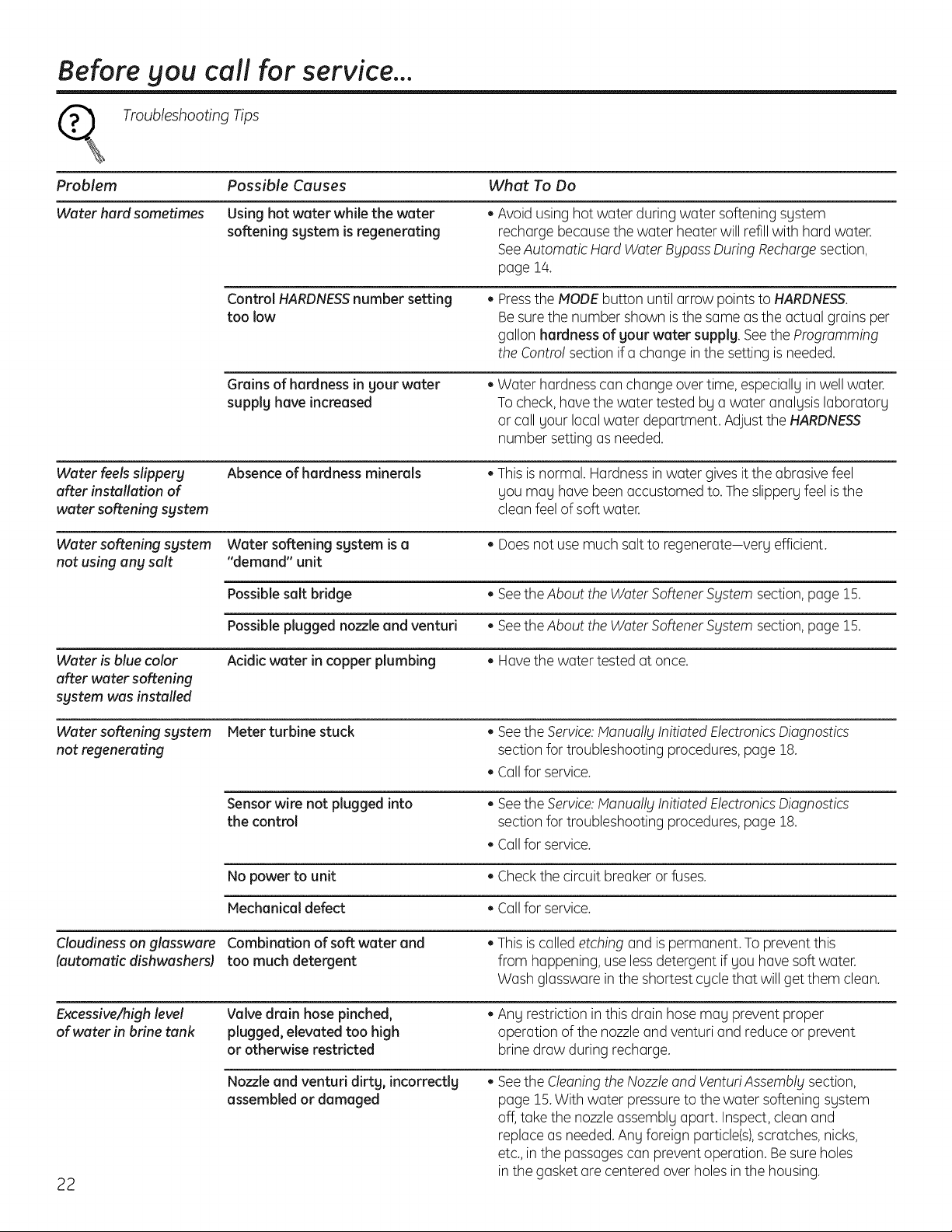
Before you call for service...
Troubleshooting Tips
Problem Possible Causes What To Do
Water hard sometimes Using hot water while the water
softening sgstem isregenerating
Control HARDNESS number setting
too low
Grainsof hardness in sour water
supplghave increased
• Avoid usinghotwater during water softeningsgstem
rechargebecause thewater heaterwillrefill with hard water.
SeeAutomatic Hard Water Bypass During Recharge section,
page 14.
• Pressthe HODE button untilarrow points to HARDNESS.
Be sure thenumber shown is thesame as the actual grainsper
gallon hardness of your water supplg. SeetheProgramming
theControl sectionif a change inthe settingis needed.
• Water hardnesscanchangeovertime,especiallg in well water.
Tocheck, have thewater tested bya water analysislaboratory
or call yourlocalwater department. Adjust the HARDNESS
number settingasneeded.
Water feels slippery Absence of hardness minerals • This is normal. Hardness in water gives ittheabrasive feel
after installation of you mag havebeen accustomedto. The slippery feel isthe
water softeningsystem cleanfeel ofsoftwater.
Water softening system Water softening sgstem is a • Does notusemuch salt toregenerate-very efficient.
not using any salt "demand" unit
Possible saltbridge • SeetheAbout theWater SoftenerSystem section, page 15.
Possible plugged nozzle and venturi • SeetheAbout theWater SoftenerSgstem section, page 15.
Water is blue color Acidic water incopper plumbing • Have the water tested at once.
after water softening
system was installed
Water softening system Meter turbine stuck • See the Service: Manually Initiated Electronics Diagnostics
not regenerating section fortroubleshooting procedures, page 18.
Callfor service.
Sensor wire not plugged into • See the Service: Manually Initiated Electronics Diagnostics
the control sectionfortroubleshooting procedures, page 18.
• Callfor service.
Nopower to unit • Check thecircuitbreakeror fuses.
Mechanical defect • Callfor service.
Cloudinesson glassware Combination ofsoft water and • This is calledetching and ispermanent.Toprevent this
(automatic dishwashersl too much detergent from happening, useless detergent ifyouhavesoftwater.
Wash glasswarein the shortest cyclethat willgetthem clean.
Excessive/high level Valve drain hosepinched, • Ang restriction in this drain hosemag prevent proper
ofwater in brine tank plugged, elevated too high operation ofthenozzleand venturi and reduce or prevent
or otherwise restricted brine draw during recharge.
22
Nozzle and venturi dirts, incorrectlg
assembled or damaged
• Seethe CleaningtheNozzle and VenturiAssemblg section,
page 15.With water pressure to thewater softening system
off, take thenozzleassembly apart. Inspect, cleanand
replaceasneeded.Anyforeign particle(s),scratches, nicks,
etc.,in the passages canprevent operation. Be sure holes
in thegasketare centered overholes in the housing.
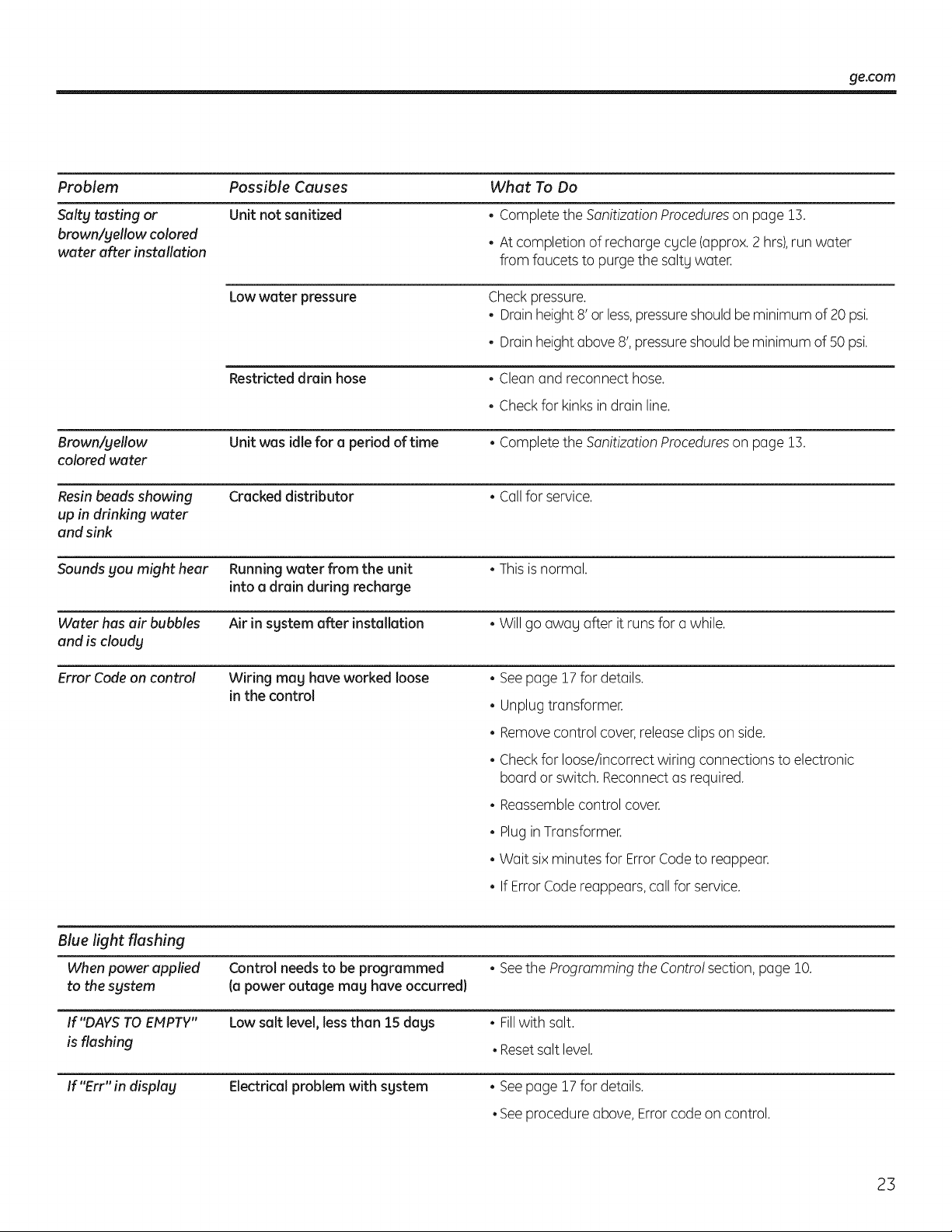
ge.com
Problem
Saltg tasting or
brown/gellow colored
water after installation
Brown/yellow
colored water
Resin beads showing
up in drinking water
and sink
Possible Causes
Unit not sanitized
What To Do
• Complete the Sanitizotion procedures on page !3.
• Atcompletionof rechQrgecycle(Qpprox.2 hrs),run water
from faucets topurge thesQItywater.
Lowwater pressure Check pressure.
• DrQinheight8' or less,pressureshould be minimum of20 psi.
• DrQinheightabove 8', pressureshouldbe minimumof50 psi.
Restricted drain hose • Cleon and reconnecthose.
• Check forkinksindrain line.
Unit was idle for a period oftime •Complete the Sanitizotion Procedureson pQge15.
Cracked distributor • Coilfor service.
Soundsgou might hear Running water from the unit • This is normal.
into a drain during recharge
Water hasair bubbles Air in sgstem after installation • Will go away after itrunsfora while.
and iscloudg
Error Code on control Wiring meg have worked loose
in the control
• See pQge17for details.
• Unplug transformer.
• Removecontrol cover,releQseclips on side.
• Check forloose/incorrectwiring connections toelectronic
boQrdor switch. Reconnect asrequired.
• ReQssemblecontrol cover.
• PluginTransformer.
• Wait six minutesforError Codeto reQppeQr.
• If Error Code reQppeQrs,callforservice.
Blue light flashing
When power applied Control needs to be programmed • See the Progromming the Contro! section, pQge lO.
tothe sgstem (a power outage mag haveoccurred}
If"DAYS TO EMPTY" Lowsalt level, less than 15 dags • Fillwith sQIt.
isflashing • Reset sQIt level.
If"Err" in display Electrical problem with sgstem • See pQge 17for details.
• See procedure above, Errorcode on control.
23

Notes.
24

Notes. ge.com
25

Notes.
26
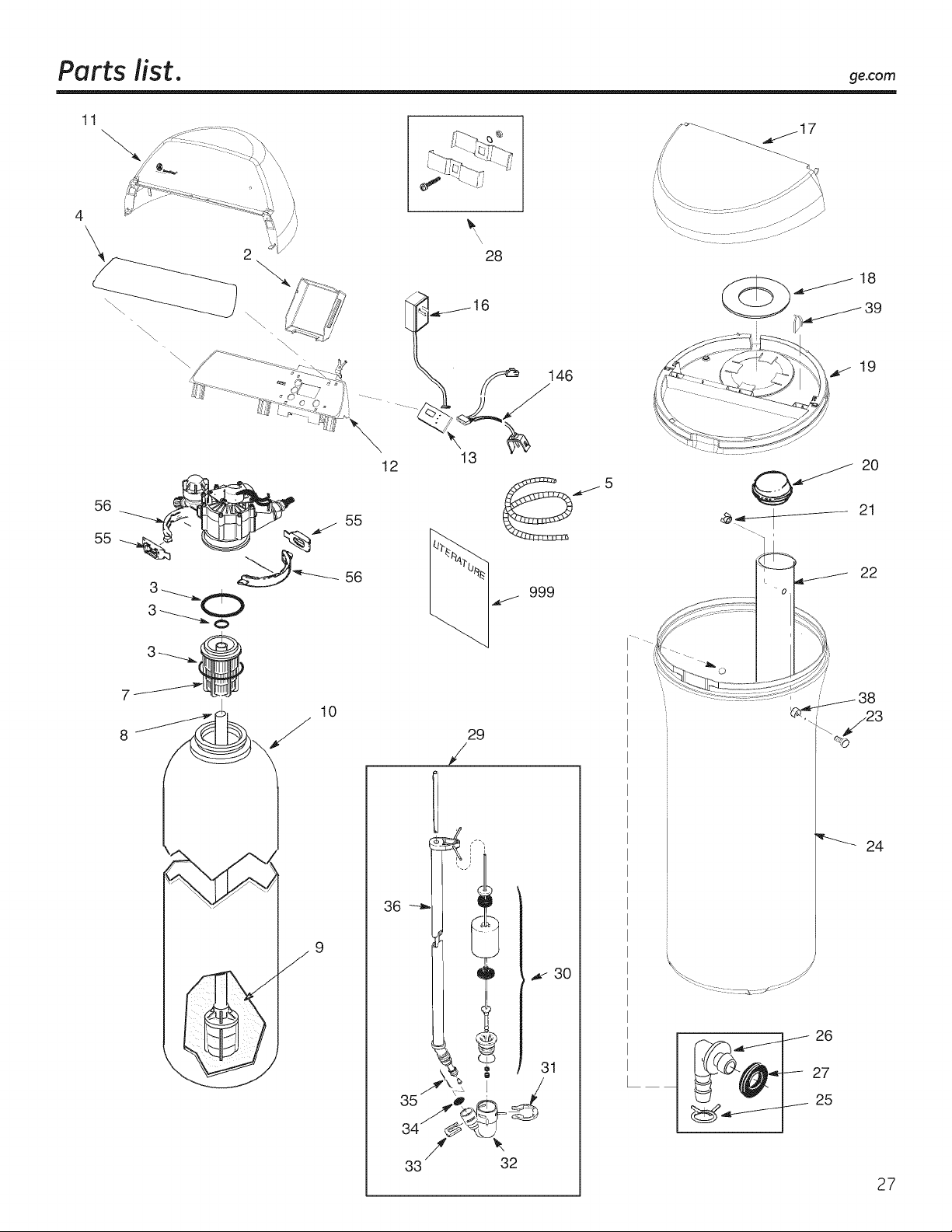
Parts list. ge.com
11
4
\\
\\
56
55
_./ 55
56
10
9
28
16
146
13
12
29
/
22
'_ 24
26
27
25
27
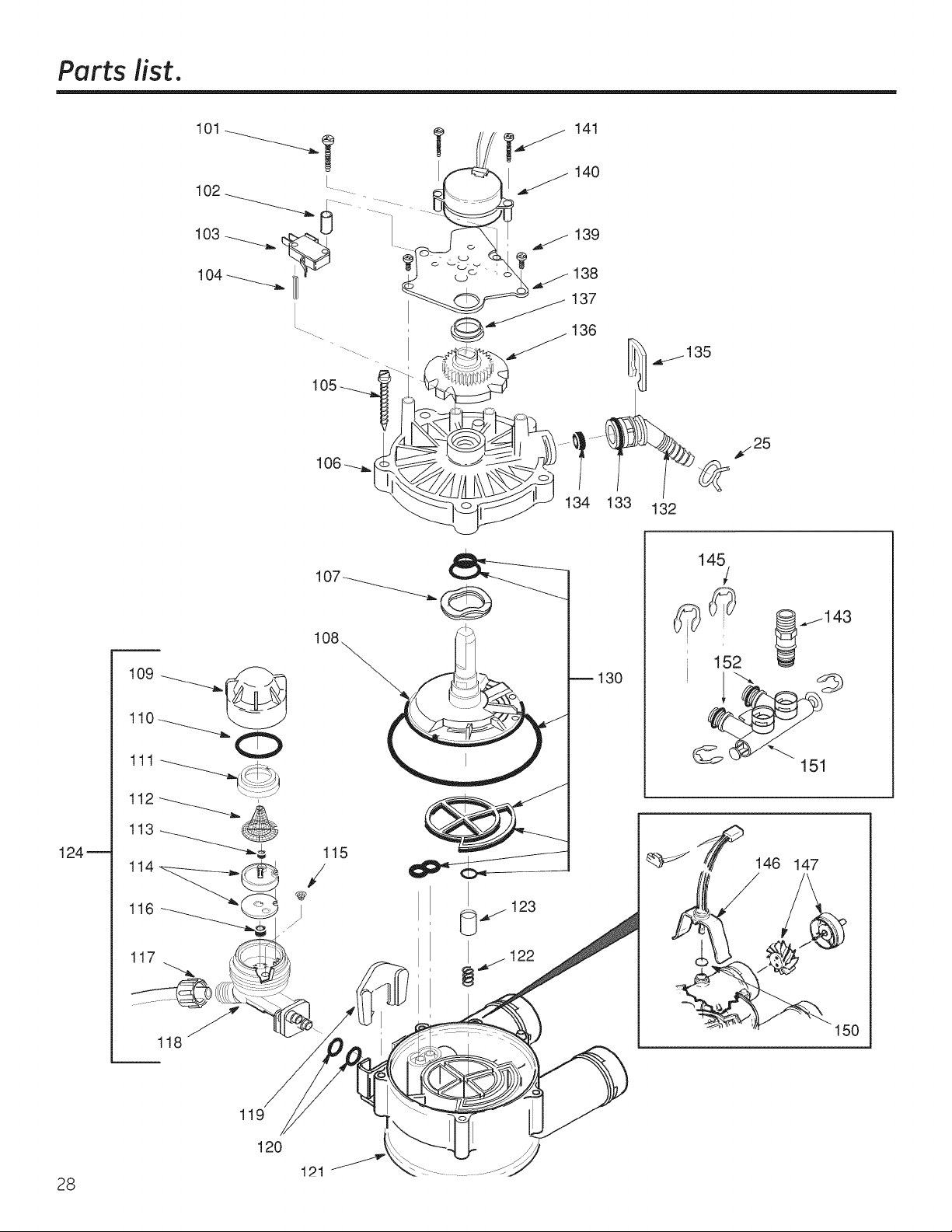
Parts list.
139
134 133
132
_¢,25
124_
117
118
130
146 147
150
28
119
120
121
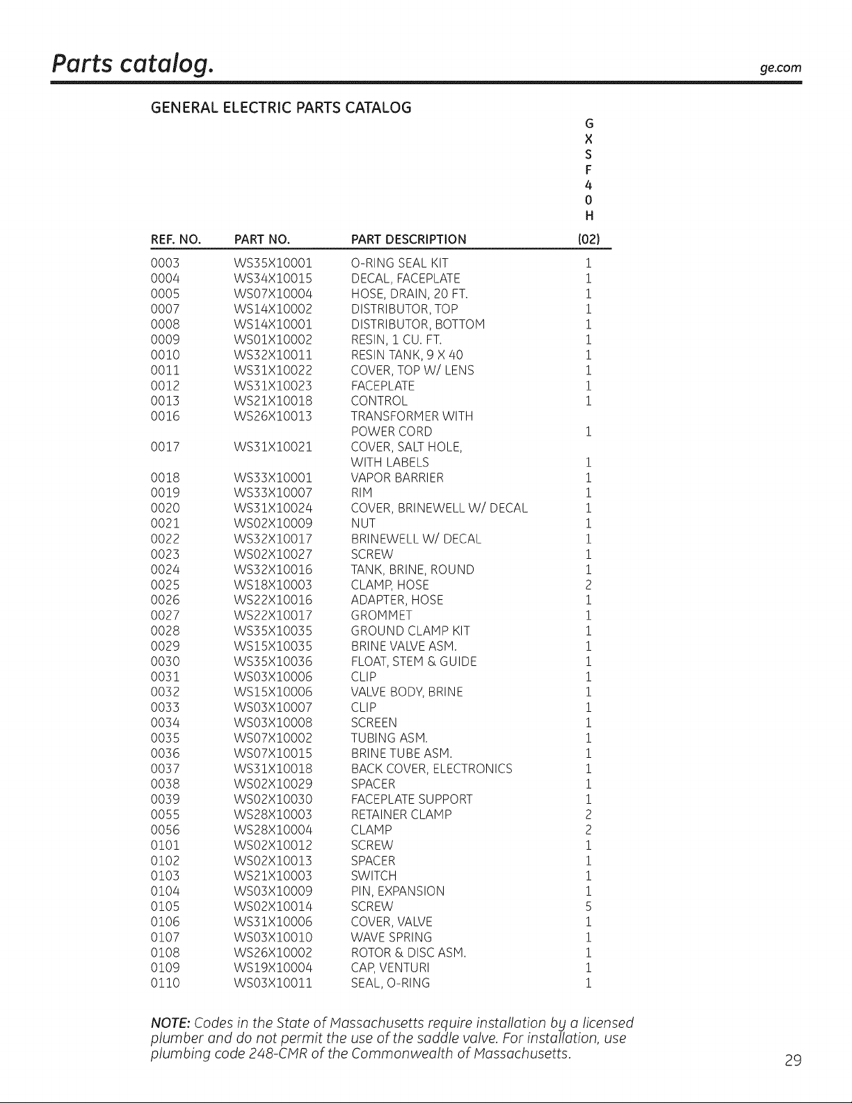
Parts catalog, ge.com
GENERAL ELECTRIC PARTS CATALOG
REF. NO. PART NO. PART DESCRIPTION
0003 WS35X!O001 O-RING SEAL KIT
0004 WS34X!O0!5 DECAL, FACEPLATE
0005 WSO7X!O004 HOSE, DRAIN, 20 FT.
0007 WS!4X!O002 DISTRIBUTOR, TOP
0008 WS!4X!O00! DISTRIBUTOR, BOTTOM
0009 WSO1X!O002 RESIN, 1 CU. FT.
00!0 WS32X!O0!! RESIN TANK, 9 X 40
00!1 WS31X!0022 COVER,TOP W/LENS
0012 WS31X!0023 FACEPLATE
0013 WS21X!00!8 CONTROL
0016 WS26X!00!3 TRANSFORMER WITH
POWER CORD
0017 WS31X!002! COVER,SALTHOLE,
WITH LABELS
0018 WS33X!O00! VAPOR BARRIER
0019 WS33X!0007 RIH
0020 WS3!X!O024 COVER, BRINEWELL W/DECAL
0021 WSO2X!O009 NUT
0022 WS32X!0017 BRINEWELL W/DECAL
0023 WS02X!0027 SCREW
0024 WS32X!00!6 TANK, BRINE,ROUND
0025 WS!8X!0003 CLAMP, HOSE
0026 WS22X!00!6 ADAPTER, HOSE
0027 WS22X!00!7 GROMMET
0028 WS35X!0035 GROUND CLAMP KIT
0029 WS!SX!0035 BRINE VALVE ASH.
0030 WS35X!0036 FLOAT, STEM & GUIDE
0031 WSO3X!O006 CLIP
0032 WS!SX!O006 VALVEBODY, BRINE
0033 WS03XI0007 CLIP
0034 WS03XI0008 SCREEN
0035 WS07X!0002 TUBING ASH.
0036 WS07X10015 BRINE TUBE ASM.
0037 WS31X10018 BACK COVER, ELECTRONICS
0038 WS02X!0029 SPACER
0039 WS02X!0030 FACEPLATE SUPPORT
0055 WS28X!0003 RETAINER CLAMP
0056 WS28X10004 CLAMP
0!0! WS02X!00!2 SCREW
0102 WS02X!00!3 SPACER
0103 WS21X!0003 SWITCH
0104 WS03X!0009 PIN, EXPANSION
0105 WS02X!00!4 SCREW
0106 WS31X!0006 COVER,VALVE
0107 WS03X!00!0 WAVE SPRING
0108 WS26X!0002 ROTOR& DISC ASH.
0109 WS!9X!0004 CAP, VENTURI
0!!0 WS03X!00!! SEAL, O-RING
G
X
S
F
4
0
H
(02}
i
i
i
i
i
i
i
i
i
i
i
i
i
i
i
i
i
i
2
i
i
i
i
i
i
i
i
i
i
i
i
i
i
2
2
i
i
i
i
5
i
i
i
i
i
NOTE: Codes in the State of Massachusetts require installation b£ a licensed
plumber and do not permit the use of the saddle valve. For installation, use
plumbing code 248-CMR of the Commonwealth of Massachusetts.
29
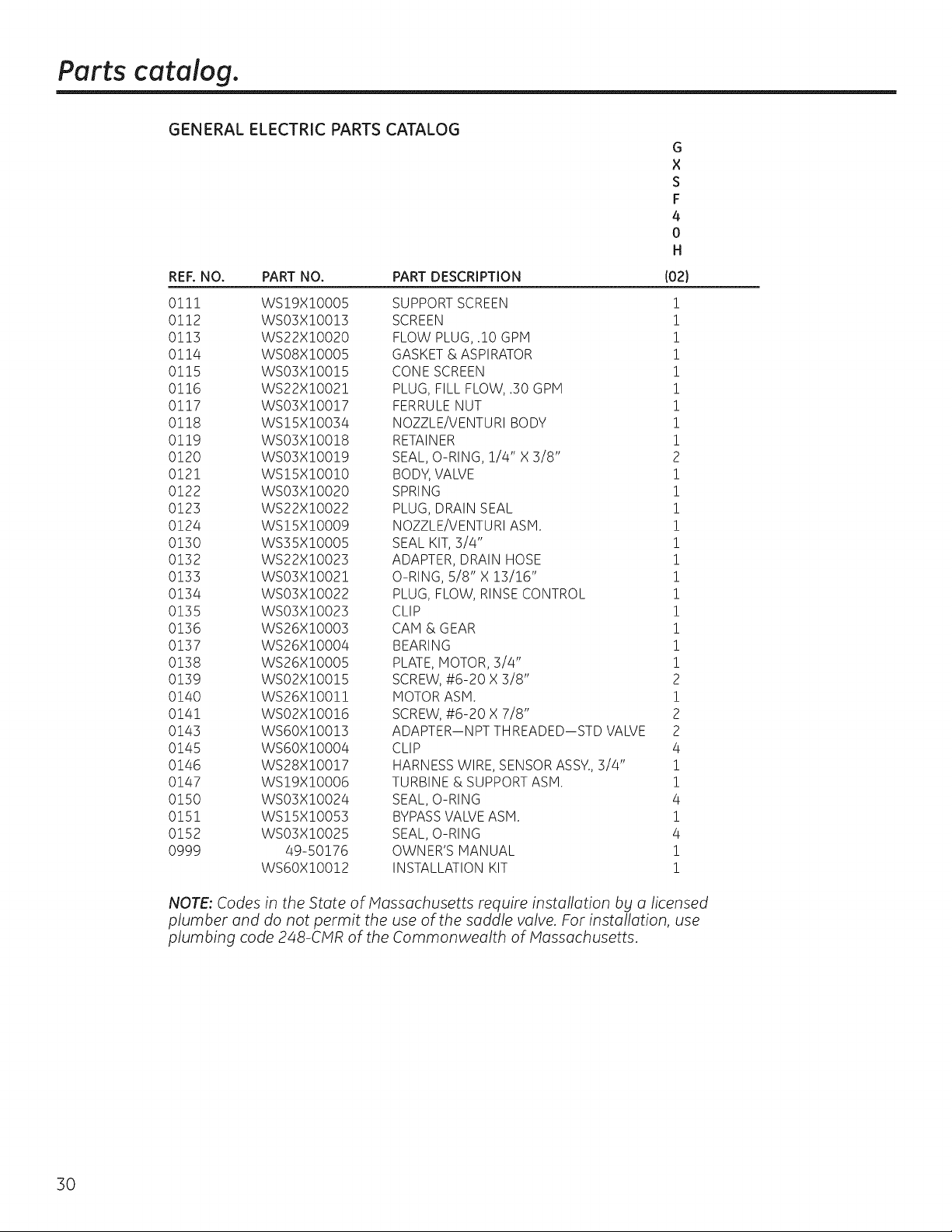
Parts catalog.
GENERAL ELECTRIC PARTS CATALOG
G
X
S
F
4
0
H
REF. NO. PART NO. PART DESCRIPTION I021
0!11 WS19XlO005 SUPPORT SCREEN !
0!12 WSO3X!OO!3 SCREEN !
0113 WS22X!0020 FLOW PLUG, .10 GPM !
0114 WSO8X!O005 GASKET & ASPIRATOR !
0115 WSO3XlO0!5 CONE SCREEN !
0116 WS22X!002! PLUG, FILL FLOW, .30 GPM !
0117 WSO3X!O0!7 FERRULENUT !
0118 WS!SX!O034 NOZZLE/VENTURI BODY !
0119 WS03X!00!8 RETAINER 1
0120 WS03X!00!9 SEAL, O-RING, 1/4" X 3/8" 2
0121 WS!5X!O0!O BODY,VALVE !
0122 WS03X!0020 SPRING !
0123 WS22X!0022 PLUG, DRAIN SEAL !
0124 WS!5XlO009 NOZZLE/VENTURI ASM. !
0130 WS35X!O005 SEAL KIT, 3/4" !
0132 WS22X!0023 ADAPTER, DRAIN HOSE !
0133 WS03X!002! O-RING, 5/8" X 13/16" !
0134 WS03X!0022 PLUG, FLOW, RINSE CONTROL !
0135 WS03X!0023 CLIP !
0136 WS26X!0003 CAM &GEAR !
0137 WS26X!0004 BEARING !
0138 WS26X!0005 PLATE,MOTOR, 3/4" !
0139 WS02X!00!5 SCREW,#6-20 X 3/8" 2
0140 WS26X!00!! MOTOR ASH. !
0141 WS02X!00!6 SCREW,#6-20 X 7/8" 2
0143 WSGOX!00!3 ADAPTER--NPT TH READED--STD VALVE 2
0145 WSGOX!O004 CLIP 4
0146 WS28X!00!7 HARNESS WIRE, SENSORASSY., 3/4" !
0147 WS!9X!0006 TURBINE & SUPPORTASH. !
0150 WS03X!0024 SEAL, O-RING 4
0151 WS!SX!0053 BYPASSVALVEASH. !
0152 WS03X!0025 SEAL, O-RING 4
@999 49-50176 OWNER'S MANUAL !
WSGOX!00!2 INSTALLATION KIT !
NOTE: Codes in the State of Massachusetts require installation b£ a licensed
plumber and do not permit the use of the saddle valve. For installation, use
plumbing code 248-CMR of the Commonwealth of Massachusetts.
30
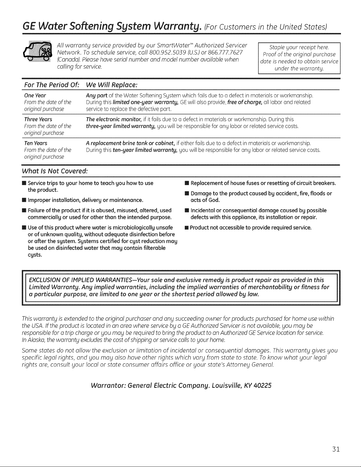
GE Water Softening System Warranty. (For Customers in the United States)
All warranty service provided by our SmartWater T"Authorized Servicer
Network. Toschedule service, call 800.952.5039 (U.&) or 866.777.7627
(Canada). Pleasehave serial number and model number available when
calling for service.
Staple gout receipt here.
Proofof the original purchase
date isneeded to obtain service
under the warrants.
For The Period Of:
We Will Replace:
Ang part oftheWater Softening System which fails due to a defectin materialsor workmanship.
During this limited one-gear warrants, GEwillalsoprovide,freeof charge, all labor and related
service toreplacethedefective part.
One Year
From the dateofthe
origina! purchase
Three Years The electronic monitor, ifitfails due toa defectin materialsor workmanship. During this
From the dateofthe three-gear limited warrants, you willbe responsiblefor any labor or relatedservice costs.
origina! purchase
Ten Years A replacement brine tank or cabinet, if eitherfails due to a defect in materialsor workmanship.
From the dateofthe During this ten-gear limited warrants, youwillbe responsibleforany labor or related servicecosts.
origina! purchase
What Is Not Covered:
m Service trips to sour home to teach Sou how to use
the product.
mImproper installation, delivery or maintenance.
I Failureof the product ifitis abused, misused, altered, used
commerciallg or usedfor other than the intended purpose.
I Use of this product where water ismicrobiologically unsafe
or of unknown quality, without adequate disinfection before
or after the system. Systems certified for cyst reduction may
be used on disinfected water that meg contain filterable
cgsts.
IIReplacement of housefusesor resetting ofcircuit breakers.
I Damage to the product caused byaccident, fire, floods or
actsof God.
I Incidental or consequential damage caused bg possible
defects with this appliance, its installation or repair.
[]Product not accessibleto provide requiredservice.
EXCLUSION OFIMPLIED WARRANTIES--Your sole and exclusive remedy is product repair as provided in this
Limited Warranty. Any implied warranties, including the implied warranties of merchantability or fitness for
a particular purpose, are limited to one gear or the shortest period allowed by law.
This warrants isextended to the original purchaser and ang succeeding owner for products purchased for home use within
the USA. If the product islocated in an area where service bg a GEAuthorized Servicer is not available, Sou mag be
responsible for a trip charge or Sou mag be required to bring theproduct to an Authorized GE Service location forservice.
In Alaska, the warrants excludesthe cost ofshipping or service calls tosour home.
Some states do not allow the exclusion or limitation of incidental or consequential damages. This warrants gives Sou
specific legal rights, and Sou mag also have other rights which varg from state to state. Toknow what gout legal
rights are, consult gout local or state consumer affairs office or gout state's Attomeg General.
li
Warrantor: General Electric Company. Louisville, KY40225
31
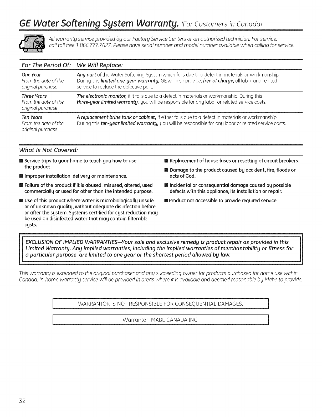
GE Water Softening System Warranty. (ForCustomers in Canada)
Allwarranty serviceprovidedby our Factory ServiceCentersor anauthorized technician. Forservice,
call toll free 1.866.777.7627. Pleasehave serial number and model number available when calling for service.
For The Period Of: We Will Replace:
One Year Any part of the Water Softening System which fails due to a defect in materialsor workmanship.
From the dateofthe Duringthis limited one-gear warranty, GEwill also provide, free of charge, all labor and related
origina! purchase service to replace thedefective part.
Three Years The electronic monitor, ifitfails due to a defect in materialsor workmanship. During this
From the dateofthe three-gear limited warranty, youwillbe responsibleforany labor or relatedservice costs.
origina! purchase
Ten Years
From the dateofthe
origina! purchase
A replacement #fine tank or cabinet, if eitherfails due to a defect in materialsor workmanship.
Duringthis ten-gear limited warranty, youwillbe responsibleforany labor or related servicecosts.
What Is Not Covered:
Service trips to your hometo teach you howto use
the product.
m Improper installation, delivery or maintenance.
m Failureofthe product if itisabused, misused, altered, used
commercially or usedfor other than the intended purpose.
m Useofthis product where water ismicrobiologically unsafe
or of unknown quality, without adequate disinfection before
or after the system. Systemscertified for cyst reduction may
be usedon disinfected water that may contain filterable
cysts.
ImReplacement of housefusesor resetting of drcuit breakers.
m Damage to the product caused by accident, fire, floods or
acts ofGod.
II Incidental or consequential damage caused by possible
defects with this appliance, its installation or repair.
[] Product not accessible to provide required service.
EXCLUSION OF IMPLIED WARRANTIES--Your sole and exclusive remedy is product repair as provided in this
Limited Warranty. Any implied warranties, including the implied warranties of merchantability or fitness for
a particular purpose, are limited to one gear or the shortest period allowed by law.
This warrant_l isextended to the original purchaser and an_l succeeding owner for products purchased for home usewithin
Canada. In-home warrantbt service will be provided in areas where itisavailable and deemed reasonable bbt Mabe to provide.
WARRANTOR ISNOT RESPONSIBLEFOR CONSEQUENTIAL DAMAGES.
Warrantor: MABECANADA INC.
32
Informaci6n de seguridad .... 34
Instrucciones
de instalaci6n ............... 35-45
Instrucciones paso pot paso .... 38-45
Instrucciones de operaci6n
C6mo limpiar la ensambladura
de la boquilla g el Venturi .......... 48
C6mo romper un puente de sal ..... 47
Funciones ......................... 49
Servicio .................... 46, 50-52
Sistema de descalcificaci6n
de agua ....................... 46-52
Cuidado y limpieza ............ 53
Consejos para la soluci6n
de averias ................... 54-56
Soporte ul cliente
Garantia ........................... 62
Lista de partes/cat_logo ........ 58-61
Soporte al consumidor ............. 63
Escriba aqui los n(_meros de modelo
y de lu serie:
Modelo No.
Serie No.
Para encontrar estos nOmeros,
levante la cubierta g mire en el borde,
debajo del panel del control.
33
INFORMACION IMPORTANTE DE SEGURIDAD.
LEA TODAS LAS INSTRUCCiONES ANTES DEL USO.
ADVERTENCIA
Pot su seguridad, se debe seguir la informaci6n en este manual con el fin de reducir el riesgo de
una descarga eldctrica, dahos a la propiedad o dahos personales.
PRECAUCIONES DESEGURIDAD
Reviseg cumpla contodos los cbdigos estatales g
locales. Observelas pautas aqufpresentadas.
iiiB,
Tenga cuidado al manipular el sistema de
descalcificaci6n de agua.No Io voltee, deje caer,
arrastre o coloqueen protuberanciasextremas.
Lossistemasde descalcificaci6n de agua que utilicen
clorurode sodio (sadpara la recargaagregan sodio al
agua.Laspersonas que siguen dietasconrestricciones
de sodio deben considemr e! sodio adiciona! como
partede suconsumo general. E!c!orumdepotasio
puedeservir como una altemativa pare e! dorum de
sodio de sudescalcificador.
Elsistema de descalcificaci6n de agua funciona
solamentecon 24 voltios-60Hz.Cercidresede usar
exclusivamentee! transformador incluido.
Utilice Onicamente salespara descalcificaci6n
del agua,al menos con99,5% de pureza. Se
recomiendan las sales en PEPITAS,BOLITAS
o SALGRUESASOLAR.No utilice sales en roca,
bloque, granuladas o sales para la elaboraci6n
de helados._stas pueden contener suciedad g
sedimentos, o pasta g masa g podrian crear
problemas de mantenimiento.
Hantenga la tapa del orificio de la sal en su lugar
en el descalcificadora menos que est@realizando
mantenimiento o reponiendo la sal.
ADVERTENCIA: Nou,,con agua
que sea microbiol6gicamente insegura o de calidad
desconocidasinIlevara cabola desinfecci6n
adecuada antes o despu_sdel sistema.
Eltransformador se debe conectar Onicamente
a un tomacorriente interiorconconexi6n a tierra
de 120voltios.
INSTALACI()N CORRECTA
Este sistema de descalcificaci6n de agua debe instalarse correctamente _t colocarse de acuerdo alas
instrucciones de instalaci6n antes de su uso.
Instale o almacene donde no quede expuestoa
temperaturas por debajo del punto de congelaci6n
ni est@expuestoa ningOntipo de inclemencias
atmosf@icas. Siel agua Ilega a congelarse dentro
del sistema, @stepodrfaromperse.No intente dar
tratamiento al agua si se encuentra a una
temperatura potencima de 38 °C (!00 °F).
Noinstale expuestoa los ragosdirectosdel sol.
Exposici6nal sol a calor excesivospodrfancausar
distorsi6nu otros da_osa laspartes no met61icas.
Conecte a tierra de manera apropiada segQnlos
c6digos g ordenanzas aplicables.
Usesolamente fundente ysoldadurasin p!omo para
todas las conexionesde condensaci6nsoldadas,
segOnlos c6digos estatales g federales aplicables.
Elsistema de descalcificaci6n de agua requiereun
flujode agua mfnimode tres galones potminuto en la
entrada. La presi6nde entrada m6ximapermitida es de
iiiB_
125psi.Sila presi6n duranteeldfaes por encima
de 80 psi, la presi6n nocturna podrfa excederel
m(_ximo.Useuna vcilvulareductora de presi6n
para reducir el flujosi esnecesario.
Lasresinas de descalcificaci6npodrfan degradarse
antela presenciade cloropotencima de 2 ppm.
Siustedtieneuna cantidad de cloromagora @sta,
quizcisexperimenteuna vidamenorde la resina.
Enestas condiciones,esposibleque quiera
considerar la compra de un sistema defiltraci6n
del puntode admisi6n para casas GEcon un filtro
reductor de cloro.
kADVERTENCIA: Desechetodaslas
partes g los materialesde embalaje no utilizados
despu@sde la instalaci6n. PartespequeSas
restantes despu@sde la instalaci6npodrfan
representar un peligro de asfixia.
LEAYSIGAESTAINFORIACION DESEGURIDADCUIDADOSAIENTE.
GUARDE ESTASINSTRUCCiONES
34
I strucciones
dei stalaci"
SistemaSuavizantede Agua
Modelos G×SF35E g G×SF40H
_ tiPreguntas? Llame 800.GE.CARES (800.432.2737) o Visite nuestra p6gina en la red en: ge.com
i
ADVERTENCIA: Leaestemanualensutotalidad.Noseguir todas las pautas g normas
podria causar lesiones personales o da5os a la propiedad.
• Consulte con la autoridad de obras p6blicas estatal/Iocal para los c6digos de plomeria. Deber6 seguir
estas pautas para instalar el sistema de filtrad6n de agua.
NOTA: No cumplir con estas instrucciones de instalaci6n invalidar6 la garantia del producto, g el instalador
ser6 responsable por cualquier servido, reparad6n o da5os causados.
ANTES DEEMPEZAR LA INSTALACI6N
Lea estas instrucdones completa g
cuidadosamente.
• IMPORTANTE - Guardeestas
instrucciones para usa del inspector local.
• IMPORTANTE -Observetodoslos
c6digos g ordenanzas vigentes.
• Nota alinstalador - AsegOrese de dejarestas
instrucciones al consumidor.
• Nota al consumidor - Conserve estas
instrucciones para consultas posteriores.
• Lo instoloci6n apropiada es la responsabilidad
del instolodor.
• Las averias del producto causadas par una
instalaci6n inadecuada no estan cubiertas par
la garantia.
• Debe existir una valvula de cierre disponible o se
debe agregar una cerca al punto de instalaci6n.
RECOMENDACIONES IMPORTANTES
PARA LA INSTALACION
• En el estado de Massachusetts, la instalaci6n
debe ajustarse al C6digo de P]omer[a 248 CMR.
Consulte a su plomero certificado.
• Use solamente fundente g soldadura sin plomo
para todas las conexiones de condensaci6n
soldadas, segOn los c6digos estatales g federales
aplicables.
• Conecte el descalcificador en la tuberia de
suministro principal antes del calentador de
agua. NO HAGA PASARAGUA CALIENTE A
TRAVES DEL DESCALCIFICADOR. La temperatura
del agua qua pase a trav6s del descalcificador
debeser manor de 49 °C (120 °F).
35
RECOMENDACIONES IMPORTANTES
PARA LA INSTALACION {CONT.)
Tengacuidado cuando manipule el
descalcificador. No Iocoloque boca arriba,
ni Iodeje caer,ni Ioarrastre, ni Io apoge
en protuberancias.
La presi6n de entrada maxima permitida es de
125 psi. Si la presi6n durante el dia es par encima
de 80 psi, la presi6n nocturna podria exceder el
maxima. Use una valvula reductora de presi6n
para reducir el flujo si es necesario. (Agregar
una valvula reductora de presi6n podria reducir
el fiujo.)
El sistema de descalcificaci6n funciona
solamente con 24 voltios-60 Hz.Cerci6rese de
usar exclusivamente el transformador incluido.
Cerci6rese de que el tomacorriente el6ctrico g el
transformador estan en el interior de un recinto
para protegerlos de la humedad.
Consulte la secci6n Donde instalar el
descalcificador para mas detalles.
-_ADVERTENCIA: Nousecon agua
que sea microbiol6gicamenteinsegurao de
calidaddesconocida sinllevara cabola
desinfecci6nadecuada anteso despu6s del
sistema. El agua debe probarse peri6dicamente
para verificar que el sistema se encuentra
funcionando satisfactoriamente.
• Partes pequeflas restantes despu6s de la
instalaci6n podrian representar un peligro
de asfixia. Deseche con toda seguridad.
Instruccionesde instalaci6n
DESEMPACADO E INSPECCI6N
Cerci6resede inspeccionar completamente el
descalcificador en busca de daflos duranteel envfoo partes
que puedan haberseperdido.Tambi6n reviseen busca de
da_osen la cajade envb. P6ngaseen contacto conla
compaflfa de transporte para cualquierreclamo par daflo
o p@dida.Elfabricante no es responsable par daflos sufridos
duranteel tr6nsito.
LaspartespequeBasnecesariasparainstalarel
descalcificadorse encuentranen una piezadecart6n
termoconformada.Paraevitarla p@didade laspartes
peque_as,mant6ngalasenel paquetetermoconformado
hastaqueustedest6listopara usarlas.Cerci6resede no
descartarcomponentesque podrianestarescondidos
enelembalage.
HERRAMIENTAS Y MATERIALES
NECESARIOS PARA LA INSTALACI6N
• Alicates
• Destornillador
• Cinta detefl6n
• Cuchilla
• DosIlavesajustables
• Sepueden requerir herramientasadicionales,si se
necesita efectuarmodificacionesa la plomerfa de la
vivienda.
• Losaccesoriosde entrada ysalidaincluidosconel
descalcificadorest6n adaptadores macho NPTde 1"
(2,5cm). Debemantener un tamano igual o mayor de
tubas que los tubas del suministro del agua,haciala
entrada ysalida del descalcificador.Luegouselos
adaptadores necesarios para conectar el suministro de
agua,hacialos adaptadores macho NPTde 1" (2,5cm).
• Usela v61vulade bypassincluidapara instalar
el descalcificador.La v61vulade bypassle permite
desconectar el suministro de agua hacia el
descalcificadorpara dectuar servicio,pero aOnmantiene
el agua Ilegando alas tuberfasde la casa.Los
adaptadores macho NPTa que nos referimos
anteriormente se conectan a la v61vulade bypass
conlas tuercas garandelasincluidas.
Utilice material de conexi6nituberia apropiado (par
ejemplo: cobre,lat6n, galvanizado o CPVC)para conectar
los adaptadores pl6sticos NTPde 1" a la plomerfa de la
vivienda.
• Siuna mangueraadicionalesnecesariapara el drenaje
de lav61vulayel tanquede sal,usted la puede solicitar
en AccesoriosGEIlamando al 800.626.2002,no. de parte
WS07X10004.
• Sinecesitauna v61vularfgidade drenaje para cumplir
conlos c6digos de plomeria, podr6 comprar las partes
necesariaspara conectarun drenaje detuberia de cobre
o pl6stico de 1/2" (1,27cm). Consulteel Paso4.
• Saldel descalcificadoren una pepitalimpia o bolita
de agua es necesaria para Ilenar eltanque de agua
salmuera. Consulte el Paso 8.
36
DONDE INSTALAR
EL DESCALCIFICADOR
Coloqueel descalcificadorIom6scercanoposiblea un
sumidero,o a otropuntodedrenajeo columnade
suministro.
• Serecomienda que los grifos externosse dejen con agua
dura para asi ahorrar agua descalcificada g sal.
• No instale el descalcificador en un lugar donde se pueda
congelar.Los daBosdebido el congelamiento no est6n
cubiertos par la garantia.
• No instale el descalcificador donde pueda bloquear el
acceso al calentador de agua o el acceso a lav61vulade
cierreprincipal del agua.
• Coloque el descalcificador en un lugar donde sea menos
probable que ocurradana causado par el agua si es que
eventualmente ocurriese alguna fuga. Elfabricante no
reparar6 ni pagar6 par donasocasionados par agua.
• Untomacorriente de 120voltioses necesario para
conectar eltransformador que vieneincluido.El
descalcificador tiene un cable el6ctricode 10 pies.Siel
tomacorriente est6 colocado demasiado lejos (basra 100
pies),use un cable calibre18 para conectarlo.Cerci6rese
de que el tomacorriente el_ctrico yel transformador
est_n en el interior de un recinto para protegerlos de la
humedad. Cerci6resede que el tomacorriente est6
desconectado para prevenir un carte el6ctricoaccidental.
• Sise disponea Ilevara cabola instalaci6nen el
exterior,debe tomar las medidas necesariaspara
asegurarse de que el descalcificador,la instalaci6n de
plomeria, el cableado, etc.est6n tambi6n protegidos de
los elementos(ragas delsol, Iluvia,viento, calor,frio),de la
contaminaci6n,vandalismo, etc. taly coma Io estarfan si
fueran instalados internamente. La instalaci6n en el
exterior no esrecomendada, g anula la garantia.
• Hantenga el descalcificador alejado de losrayos
directos del sol. Elcalor del solpodrfa causar distorsi6n
u arras danosa laspartes no met61icasypodrfahacer
dana a laspartes electr6nicas.
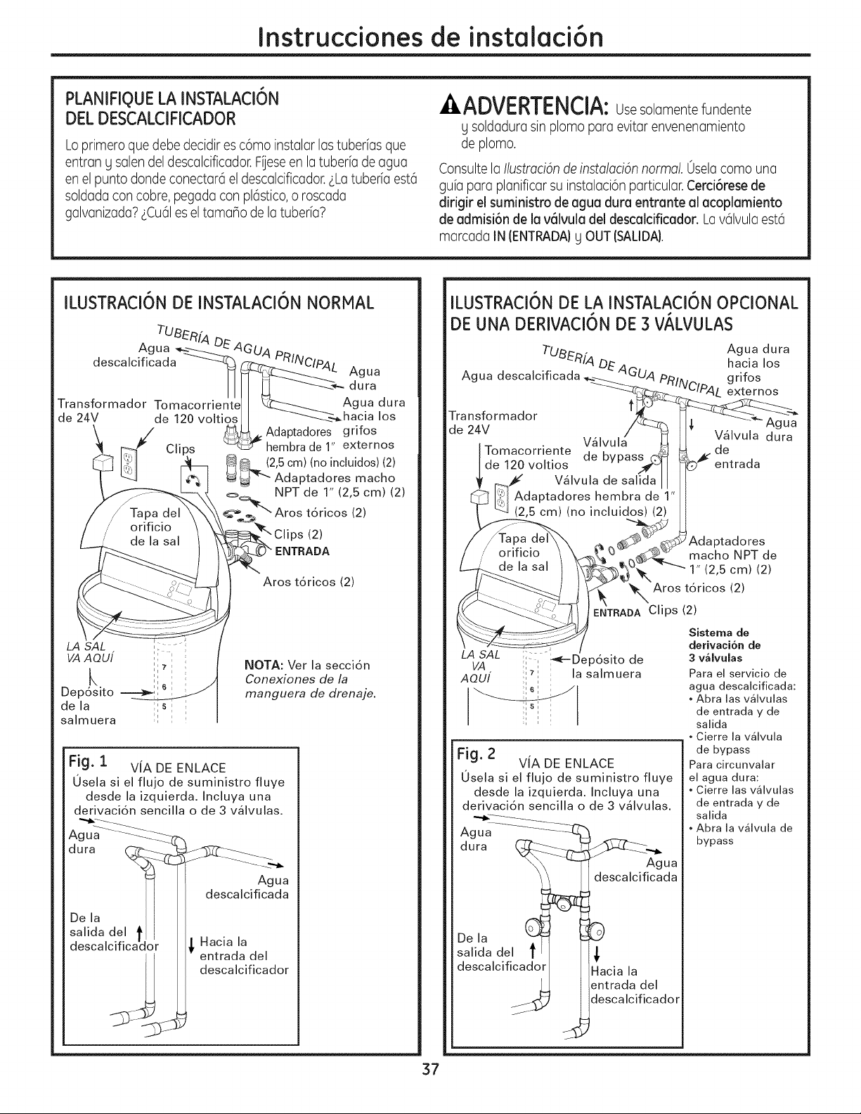
Instruccionesde instalaci6n
PLANIFIQUELA INSTALACI6N
DEL DESCALCIFICADOR
Loprimeroque debe decidires c6mo instalar las tuberias que
entran g salen del descalcificador.Fiese en latuberfa de agua
en el punto donde conectar6el descalcificador.LLatuberfa est6
soldadacon cobre, pegada conpl6stico,o roscada
galvanizada?LCu61es el tamano de la tuberfa?
,&ADVERTENCIA:Usesolamemtefundente
g soldadurasin plomo para evitar envenenamiento
de plomo.
Consulte la Ilustmcian de instalacian normal. 0selacoma una
gufapara planificar su instalaci6nparticular. Cerci6resede
dirigir el suministro de agua dura entrante al acoplamiento
de admisi6n de la v61vuladel descalcificador. Lav61vulaest6
marcada IN (ENTRADA)g OUT (SALIDA).
ILUSTRACI6N DE INSTALACI6N NORMAL
TUBER[A DE
Agua _--._"---------C_'
descalcificada -------4_
Transformador Tomacorriente
de 24V de 120 voltios
LA SAL ; -;
VAAOUI ''
k ,,
Dep6sito -=--__
i
de la ;1s: :
salmuera ;l :
____ APAL Agua
dura
gua dura
hacia los
Adaptadores grifos
_hembra de 1' externos
4,_ (2,5 cm) (no incluidos) (2)
_ Adaptadores macho
=_ NPT de 1" (2,5 cm) (2)
:__.'_"" Aros t6ricos (2)
_ Clips (2)
?" ENTRADA
Aros t6ricos (2)
NOTA: Ver la secci6n
Conexiones de la
manguera de drenaje.
Fig. i VIA DE ENLACE
0sela si el flujo de suministro fluye
desde la izquierda. Incluya una
derivaci6n sencilla o de 3 v_lvulas.
dura _.__ _3_'_-___
Agua
descalcificada
De la I I
salida del t I
descalcificador _ Hacia la
entrada del
/_. descalcificador
ILUSTRACI6N DE LA INSTALACI6N OPCIONAL
DE UNA DERIVACI6N DE 3VALVULAS
Tu_nf4
Agua descalcificada DE'4G
Transformador
de 24V
Tomacorriente
de 120 voltios
Agua dura
hacia los
g ri fos
JClp4 L externos
Agua
V_lvula dura
de
entrada
macho NPT de
1" (2,5 cm) (2)
Aros t6ricos (2)
'ENTRADAClips (2)
LA SAL :,. _--Dep6sito de
VA I I
AOU[ i_i la salmuera
Fig. 2
VIA DE ENLACE
0sela si el flujo de suministro fluye
desde la izquierda. Incluya una
derivaci6n sencilla o de 3 v41vulas.
A ua..... _._7_
g ....
dura (_
De la (_
salida del t
descalcificador
Agua
descalcificada
Hacia la
entrada del
descalcificador
Sistema de
derivaci6n de
3 valvulas
Para el servicio de
agua descalcificada:
• Abra las valvulas
de entrada y de
salida
• Cierre la valvula
de bypass
Para circunvalar
el agua dura:
•Cierre las valvulas
de entrada y de
salida
• Abra la valvula de
bypass
37
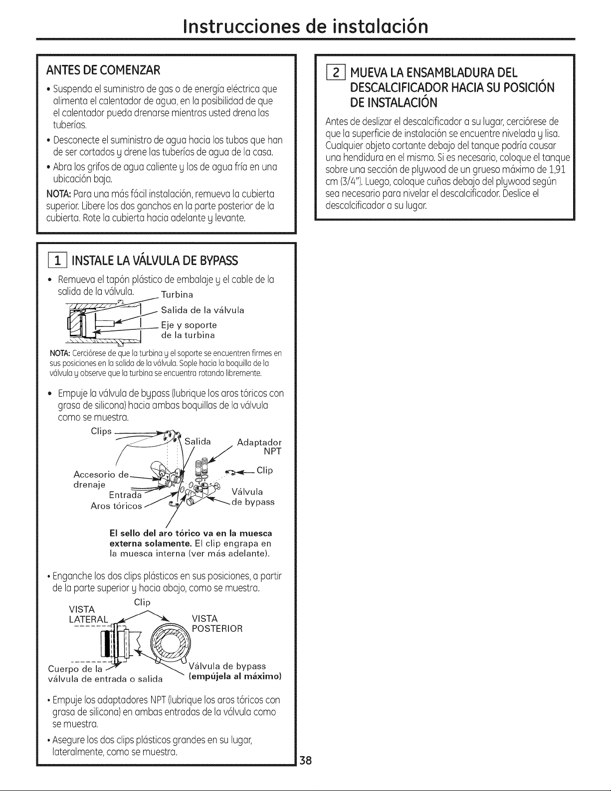
Instruccionesde instalaci6n
ANTES DE COMENZAR
• Suspenda elsuministro de gas o de energfa el6ctrica que
alimenta el calentador de agua, en la posibilidad de que
el calentador pueda drenarsemientrasusted drena las
tuberfas.
• Desconecteel suministro de agua hacialos tubas que han
de ser cortados g drene las tuberfasde agua de la casa.
• Abra los grifos de agua caliente ylos de agua frfa en una
ubicaci6n baja.
NOTA:Parauna m6s f6cil instalaci6n, remueva la cubierta
superior.Liberelosdosganchos en la parteposterior de la
cubierta.Rotela cubierta haciaadelanteg levante.
_-] MUEVALA ENSAMBLADURADEL
DESCALCIFICADORHACIA SU POSICI6N
DE INSTALACI6N
Antesde deslizareldescalcificadora su lugar,cerci6resede
quela superficiedeinstalaci6nseencuentreniveladay lisa.
Cualquierobjetocortantedebajodeltanquepodriacausar
una hendiduraenel mismo.Siesnecesario,coloqueeltanque
sabreuna secci6ndeplywooddeungruesom6ximode1,91
cm (Bi4").Luego,coloquecuBasdebajodelplywoodsegOn
seanecesarioparanivelarel descalcificador.Desliceel
descalcificadorasu lugar.
r-_ INSTALELA VALVULADE BYPASS
• Remuevael tap6n pl6sticode embalajeg el cable de la
salida de lav61vula. Turbina
"_ Salida de la v_lvula
Eje y soporte
de la turbina
NOTA:Cerci6resede quelaturbinag el soporteseencuentrenfirmesen
susposicionesen lasalidadelav61vula,Soplehacialaboquiltade la
v61vulag observequelaturbina seencuentrarotandolibremente,
Empuje la v61vulade bypass(lubrique los aros t6ricos con
grasade silicona)haciaambas boquillas de lav61vula
coma se muestra.
_f_ Salida . Adaptador
Chps --_Y S NPT
Clip
Accesorio de___ __._ L__ .....
drenaje _ _ Vfilvula
Entrada - _
Aros tdricos _ _ _ "_'-_de bypass
/
El sello del aro t6rico va en la muesca
externa solamente. El clip engrapa en
la muesca interna (ver m_s adelante).
• Enganche los dos clips pl6sticosen sus posiciones,a partir
de la partesuperioryhaciaabajo, coma se muestra.
Clip
VISTA
LATERAL VISTA
POSTERIOR
Cuerpo de la
v41vula de entrada o salida
de bypass
(empujela al ma×imo)
• Empujelos adaptadores NPT(lubriquelos arost6ricoscon
grasade silicona)en ambas entradas de lav61vulacoma
semuestra.
• Asegure los dosclips pl6sticos grandesen su lugar,
lateralmente, coma se muestra.
38
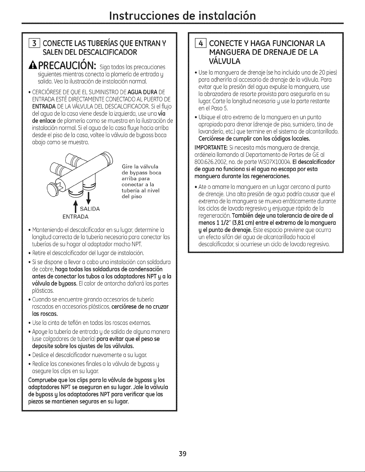
Instruccionesde instalaci6n
[_ CONECTE LAS TUBERJAS QUE ENTRANY
SALEN DEL DESCALCIFICADOR
41_ri_U_lUi_: Siga todas las precauciones
siguientes mientrasconecta la plomeriade entrada g
salida.Yea la ilustraci6n de instalaci6n normal.
• CERCIORESEDEQUEELSUHINISTRODEAGUADURADE
ENTRADAESTEDIRECTAHENTECONECTADOALPUERTODE
ENTRADADELAVALVULADELDESCALCIFICADOR.SJel flujo
del agua de la casa vienedesde la izquierda,use una via
de enlacede plomeria como semuestraen la ilustraci6nde
instalaci6nnormal. Siel agua de la casa flugehaciaarriba
desde el piso de la casa, voltee la v61vulade bgpass boca
abajo como se muestra.
t
SALIDA
ENTRADA
Gire la v41vula
de bypass boca
arriba para
conectar a la
tuberia al nivel
del piso
Manteniendo el descalcificador en su lugar,determine la
Iongitud correctade latuberfa necesaria para conectar los
tuberfasde suhogar al adaptador macho NPT.
Retireel descalcificadordel lugar de instalaci6n.
Sisedispone a Ilevar a cabouna instalaci6n consoldadura
de cobre,haga todas lossoldaduras de condensaci6n
antes de conectar lostubos a losadaptadores NPTg a la
v61vulade bgpass.Elcolor de antorcha dahar6 los partes
pl6sticas.
• Cuando se encuentre girando accesoriosde tuberia
roscados en accesorios pl6sticos,cerci6resede no cruzar
losroscas.
• Usela cinta de tefl6n en todas losroscasexternas.
• Apoyelatuberfa de entrada yde salida de alguna manera
(usecolgadores detuberia)para evitar que el peso se
deposite sabre los ajustes de las v61vulas.
• Desliceel descalcificador nuevamentea su lugar.
• Realicelos conexiones finales a lav61vulade bgpass g
asegure los clips en su lugar.
Compruebe que losclips para la v61vulade bgpass g los
adaptadores NPTseaseguran en sulugar.Jalela v61vula
de bgpass g losadaptadores NPTpara verificar que los
piezas semantienen seguras en sulugar.
CONECTE Y HAGA FUNCIONAR LA
MANGUERA DE DRENAJE DE LA
V_,LVULA
Usela mangueradedrenaje(seha incluidouna de20pies)
paraadherirlaal accesoriodedrenajede lav61vula.Para
evitarque la presi6ndelaguaexpulselamanguera,use
la abrazaderaderesorteprovistaparaasegurarlaensu
lugar.CortelaIongitudnecesariagusela porterestante
enelPaso5.
• Ubique el otroextremode la mangueraen un punto
apropiado para drenar (drenajede piso, sumidero,tinade
lavanderfa,etc.)que termine en el sistema de alcantarillado.
Cerci6rese de cumplir con los c6digos locales.
IMPORTANTE:Sinecesitam6s manguera de drenaje,
ord6nela Ilamando al Departamento de Partesde GEal
800.626.2002,no.de porte WS07X10004. Eldescalcificador
de agua no funciona si el agua no escapa por esta
manguera durante losregeneraciones.
Ateo amarre la manguera en un lugar cercano al punto
de drenaje. Una altopresi6n de agua podria causar que el
extremode la manguera se mueva err6ticamente durante
los ciclos de lavadoregresivoyenjuague r6pido de la
regeneraci6n.Tambi_n deje una tolerancia de aire de al
menos 1 1/2" (3,81cm} entre el extremo de la manguera
g el punto de drenaje. Esteespacio previene que ocurra
un efectosif6n del agua de alcantarillado haciael
descalcificador,si ocurriese un ciclo de lavadoregresivo.
39
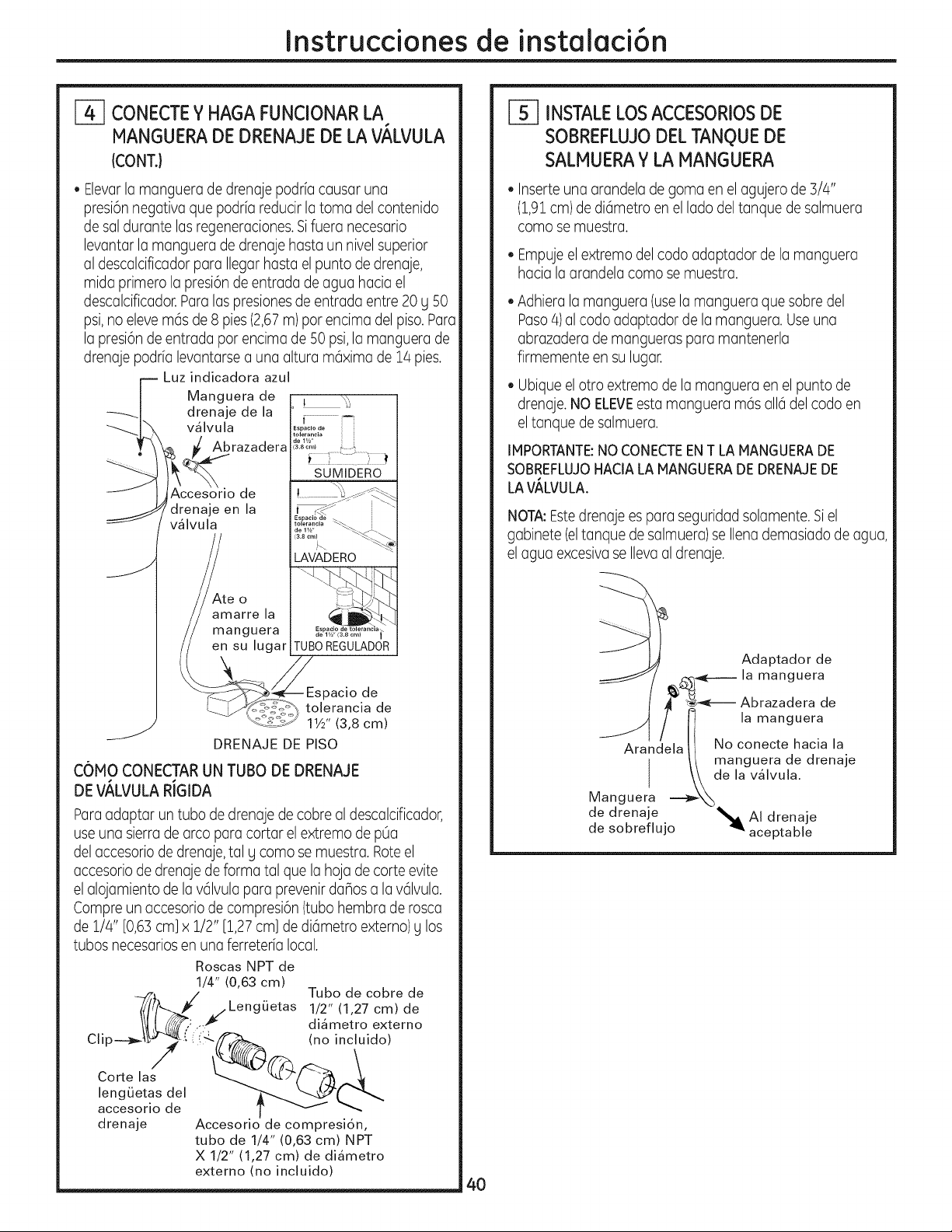
Instruccionesde instalaci6n
CONECTEYHAGA FUNCIONAR LA
MANGUERADEDRENAJEDE LA VALVULA
(CONT.}
• Elevarla manguera de drenaje podria causar una
presi6n negativa que podria reducir la toma del contenido
de sal durante las regeneraciones.Sifuera necesario
levantar la manguerade drenaje hasta un nivelsuperior
al descalcificador para Ilegar hasta el puntode drenaje,
midaprimerola presi6n de entradade agua haciael
descalcificador.Para las presionesde entradaentre20 g 50
psi,no eleve m6s de 8 pies (2,67m) par encima del piso.Para
la presi6n de entrada par encima de 50 psi,la manguerade
drenaje podria levantarse a una alturam6xima de 14 pies.
r-- Luzindicadora azul
| Manguera de t _.
_-_| drenaje de la _ _
_l"x v_lv.la r_° i-'
razadera a_c,., ¢.._,,
SUMIDERO
I ,jAccesorio de
drenaje en la ::
/ v_lvula
_te o
amarre la
manguera
en su lugar
S
TUBa REGULADOR
pacio de
tolerancia de
11/2'' (3,8 cm)
DRENAJE DE PISO
COMO CONECTAR UN TUBO DEDRENAJE
DE V,_LVULARiGIDA
Paraadaptaruntubade drenajede cobrealdescalcificador,
useuna sierrade arcoparacortarelextremode pOa
del accesorio de drenaje, talg como semuestra. Roteel
accesorio de drenaje de forma tal que la hoja de corte evite
el alojamiento de la v61vulapara prevenir danosa lav61vula.
Compre un accesorio de compresi6n (tubahembrade rosca
de 1/4" [0,6Scm]x1/2" [1,27cm]de di6metro externo)g los
tubas necesariosen una ferreteria local.
Tuba de cobre de
1/2" (1,27 cm) de
di4metro externo
(no incluido)
Roscas NPT de
1/4" (0,63 cm)
- -_,Z _F/Leng(jetas
Clip---_?{ (" i 4-
Carte las
lengLietas del
accesorio de
drenaje Accesorio de compresi6n,
tuba de 1/4" (0,63 cm) NPT
X 1/2" (1,27 cm) de di4metro
externo (no incluido)
r-_ INSTALELOSACCESORIOSDE
SOBREFLUJODEL TANQUEDE
SALMUERAY LA MANGUERA
• Inserteuna arandeladegoma en elagujerode 3/4"
(1,91cm)de di6metro en el lado deltanque de salmuera
coma se muestra.
• Empuje elextremodel codaadaptador de la manguera
haciala arandela coma semuestra.
• Adhiera lamanguera(uselamangueraque sabredel
Paso4)alcodaadaptadorde lamanguera.Use una
abrazaderade manguerasparamantenerla
firmementeen su lugar.
• Ubique el otroextremode la mangueraen el puntode
drenaje.NOELEVEesta manguera m6s all6 del codaen
eltanquedesalmuera.
IMPORTANTE:NO CONECTEENTLA MANGUERADE
SOBREFLUJOHACIALA MANGUERADE DRENAJEDE
LAV/_LVULA.
NOTA:Estedrenaje es para seguridad solamente. Si el
gabinete(eltanque de salmuera)se Ilena demasiado de agua,
el agua excesivase Ilevaal drenaje.
B
Adaptador de
,¢x-q_--.----la manguera
J _-_--- Abrazadera de
_ f _ lamanguera
Arandelall Noconectehaciala
// manguera de drenaje
I \k de la v_lvula.
Manguera. _,,-X_
de drenaje _ AI drenaje
de sobreflujo 91' aceptable
4O
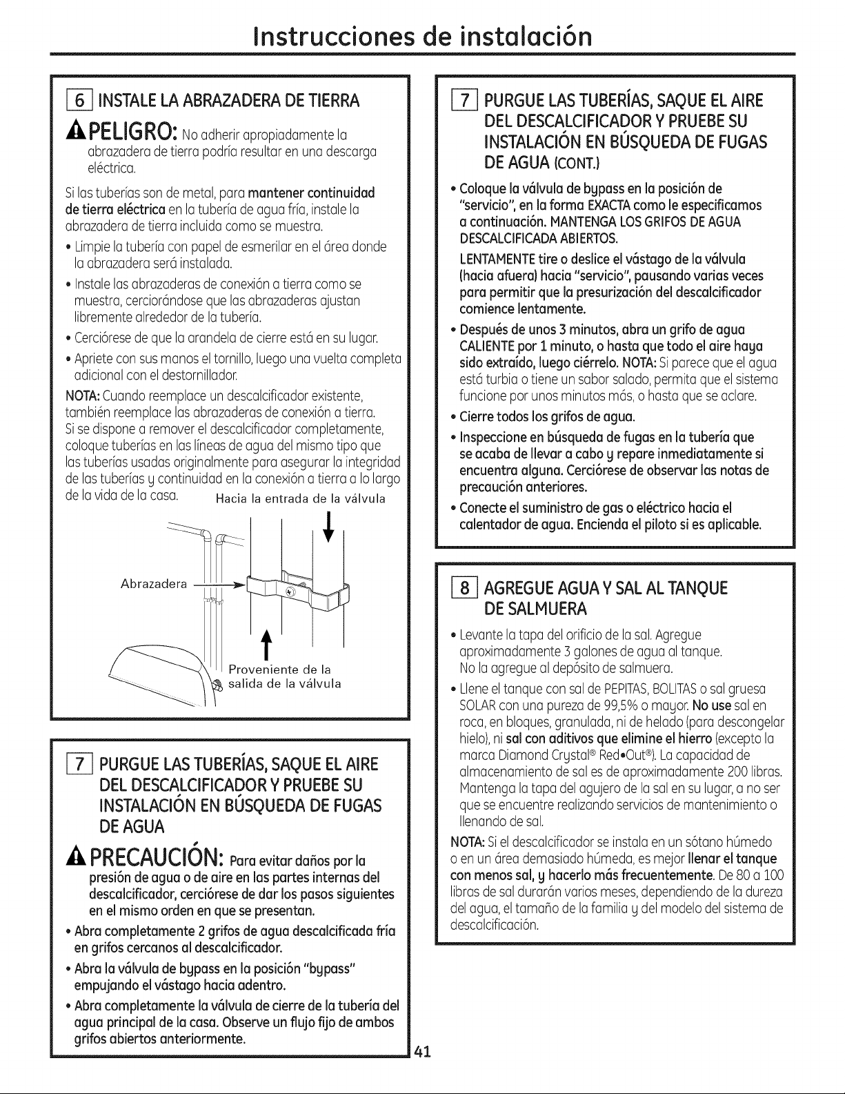
Instruccionesde instalaci6n
INSTALELA ABRAZADERADE TIERRA
-APELIGRO:No adherir apropiadamente la
abrazaderade tierrapodrfaresultaren unadescarga
el6ctrica.
Silas tuberfas sonde metal,para mantener continuidad
de tierra el_ctrica en la tuberfa de agua frfa, instale la
abrazaderade tierraincluidacoma se muestra.
• Limpie la tuberiaconpapel de esmerilar en el@ea donde
laabrazaderaser6instalada.
• Instale las abrazaderas de conexi6n a tierra coma se
muestra, cercior6ndose qua las abrazaderas ajustan
libremente alrededor de la tuber[a.
• Cerci6resede que la arandela de cierre est6 en sulugar.
• Apriete consusmanos el tornillo, luego una vuelta completa
adicional conel destornillador.
NOTA:Cuandoreemplace un descalcificador existente,
tambi6n reemplace lasabrazaderas de conexi6n a tierra.
Sise dispone a remover el descalcificador completamente,
coloque tuberfasen lasIfneasde agua del mismo tipo que
las tuberfasusadas originalmente para asegurarla integridad
de las tuberias g continuidad en la conexi6na tierraa Io largo
de la vidade la casa. Hacia la entrada de la v41vula
Abrazadera -
t
Proveniente de la
_ salida de la v41vula
[-_ PURGUELASTUBERIAS,SAQUEELAIRE
DEL DESCALCIFICADORY PRUEBESU
INSTALACION
EN BOSQUEDA DE FUGAS
DE AGUA
#
A PRECAUCION:Poroevitardaffosporla
presi6nde agua o de aire en Jaspartes internas del
descalcificador, cerci6rese de dar los pasos siguientes
en el mismo arden en qua se presentan.
• Abra completamente 2 grifos de agua descalcificada fria
en grifos cercanosal descaldficador.
• Abra la v6lvula de bgpass en la posici6n "bgpass"
empujando el v6stago haciaadentro.
• Abra completamente la v61vulade cierre de la tuberia del
agua principal de la casa.Observe un flujo fijo de ambos
gdfos abiertos antedormente.
41
[-_ PURGUELAS TUBERIAS,SAQUEELAIRE
DEL DESCALCIFICADORY PRUEBESU
INSTALACI6NEN BOSQUEDA DE FUGAS
DE AGUA(CONT.}
• Coloquela v6lvula de bgpass en la posici6n de
"servJcio",en la farina EXACTAcoma le especificamos
a contJnuacJ6n.MANTENGALOSGRIFOSDEAGUA
DESCALCIFICADAABIERTOS.
LENTAMENTEtire o deslice el v6stago de la v61vula
(haciaafuera)hacia "servicio", pausando varias veces
para permitir que la presudzaci6n del descalcificador
comience lentamente.
• Despu_s de unos3 minutos, abm un grifo de agua
CALIENTEpot i minuto, o hasta que todo el aire haga
sidoextraido, luego d_rrelo. NOTA:Sipareceque el agua
est6 turbiao tieneun saborsalado,permita que el sistema
funcione par unos minutos m6s, o basraqua se aclare.
• Cierre todos losgrifos de agua.
• Inspecdone en b6squeda de fugas en la tuberia qua
se acaba de Ilevar a cabog repare inmediatamente si
encuentra alguna. Cerd6rese de observar las notas de
precaud6n anteriores.
• Conecteel suministro de gaso el_ctrico hacia el
calentador de agua. Encienda el piloto sies aplicable.
_] AGREGUEAGUAY SALAL TANQUE
DE SALMUERA
• Levantela tapa del orificio de la sal.Agregue
aproximadamente 3 galonesde agua al tanque.
Nolaagregue al dep6sito de salmuera.
•Llene eltanque consal de PEPlTAS,BOLITASo sal gruesa
SOLARconuna pureza de 99,5% o magor. No usesal en
roca,en bloques,granulada, ni de helado (paradescongelar
hielo),ni salconaditivos que elimine el hierro (excepto la
marcaDiamondCrystal® Red,Out®).Lacapacidadde
almacenamientode salesde aproximadamente200libras.
Mantengalatapadelagujerode lasalen su lugar,a noser
queseencuentrerealizandoservJciosde mantenimientoo
Ilenando de sal.
NOTA:Siel descalcificador seinstala en un s6tano hOmedo
o en un 6teademasiado h0meda, es majorIlenar el tanque
conmenos sal, g hacedo m6s frecuentemente. De80 a 100
libras de saldurar6n varios meses,dependiendo de la dureza
del agua, el tamaho de la familia g del modelo del sistema de
descalcificaci6n.
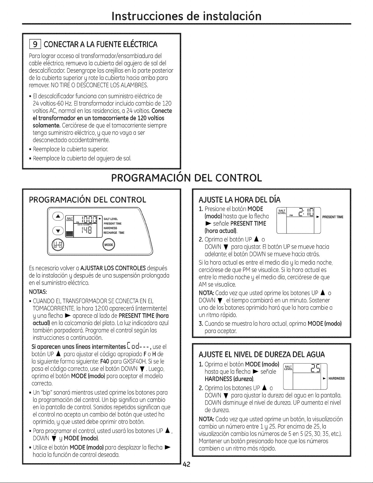
Instruccionesde instalaci6n
_-I CONECTARA LA FUENTEELI_CTRICA
Paralograraccesoaltransformadoriensambladuradel
cableel6ctrico,remuevalacubiertadelagujerode saldel
descalcificador.Desengrapelasorejillasen laparteposterior
de lacubiertasuperiorg rotelacubiertahaciaarribapara
remover.NO TIRE0 DESCONECTELOSALAMBRES.
• Eldescalcificadorfunciona con suministro el6ctrico de
24 voltios-60Hz.Eltransformador incluidocambia de 120
voltiosAC,normalen lasresidencias,a 24 voltios.Conecte
el transformador en un tomacorriente de 120voltios
solamente. Cerci6resede que el tomacorriente siempre
tenga suministro el6ctrico,g qua no vagaa set
desconectado accidentalmente.
• Reemplacela cubierta superior.
• Reemplacela cubierta del agujero de sal.
PROGRAMACI6N DEL CONTROL
PROGRAMACI6N DEL CONTROL
(_[" SALTI { N.n I--II"I SALTLEVEL
ILEVEq_MLI I--I'U L.IJ I
[ml ,-,oi J°EC,A°O T,OE
@ @
Esnecesariovolver a AJUSTARLOSCONTROLESdespu6s
de la instalaci6n g despu6s de una suspensi6nprolongada
en el suministro el6ctrico.
NOTAS:
• CUANDOELTRANSFORMADORSECONECTAEN EL
TOMACORRIENTE,la hora 12:00aparecer6(intermitente)
g una flecha I_ apareceal lado de PRESENTTIME(hora
actual} en la calcomanfa del plato. La luz indicadoraazul
tambi6n parpadear6.Programe el control segOnlas
instrucciones a continuaci6n.
, • • J- I
Siaparecen unashneasmtermltentes C ,:,o-- -, useel
bot6nUP• para ajustar elc6digoapropiado Fo H de
la siguienteforma siguiente: F40para GXSF4OH.Sisele
pasa el c6digocorrecto, use el bot6n DOWN •. Luego,
oprimael bot6n MODE(modo)para aceptar el modelo
correcto.
• Un "bip"sonarci mientrasusted oprimelos botones para
la programaci6n del control.Un bip significaun cambio
en la pantallade control.Sonidosrepetidos significan que
elcontrol no acepta un cambio del bot6nque usted ha
oprimido, g qua usteddebe oprimir otto bot6n.
• Paraprogramar el control,usted usar6los botones UP •,
DOWN • g MODE(modo).
• Utilice el bot6nMODE (modo) para desplazar la flecha I_
haciala funci6n de control deseada.
AJUSTELA HORA DEL DIA
1.Presioneel bot6nMODE _ t_l: in ]
(modalhastaquelaflecha PM UI,,-PFIESENTTmME
[ ]
I_ seBalePRESENTTIME
(horaactual).
2.Oprima el bot6nUP • o
DOWN • para ajustar. Elbot6n UPse mueve hacia
adelante;el bot6nDOWNsemueve haciaatr6s.
Sila hora actual es entreel media dfag la media noche,
cerci6resede que PM sevisualice.Sila hora actual es
entrela medianocheg el mediadia, cerci6rese de que
AM se visualice.
NOTA:Cada vezque usted oprimelosbotones UP • o
DOWN•, el tiempo cambiarci en un minuto.Sostener
uno de los botones oprimido har6 que la hora cambie a
un ritmo r@ido.
3.Cuando se muestra la hora actual,oprima MODE(modo}
para aceptar.
AJUSTEEL NIVELDE DUREZADEL AGUA
:1.Oprima el bot6nMODE(modo) .... i_J
hasta que la flecha I_ senale ..... 2S
HARDNESS(dureza). _ .ARD.ESS
2.Oprimalos botones UP• o
DOWN • para ajustar la dureza del agua en la pantalla.
DOWNdisminuge el nivel de dureza.UPaumenta el nivel
de dureza.
NOTA:Cada vez que usted oprime un bot6n, la visualizaci6n
cambia un nOmeroentre1 g 25. Parencima de 25,la
visualizaci6ncambia los nOmeros de 5 en 5 (25,30, 35, etc.).
Mantener un bot6n presionado hacequa losnOmeros
cambien a un ritmo m6s r6pido.
42
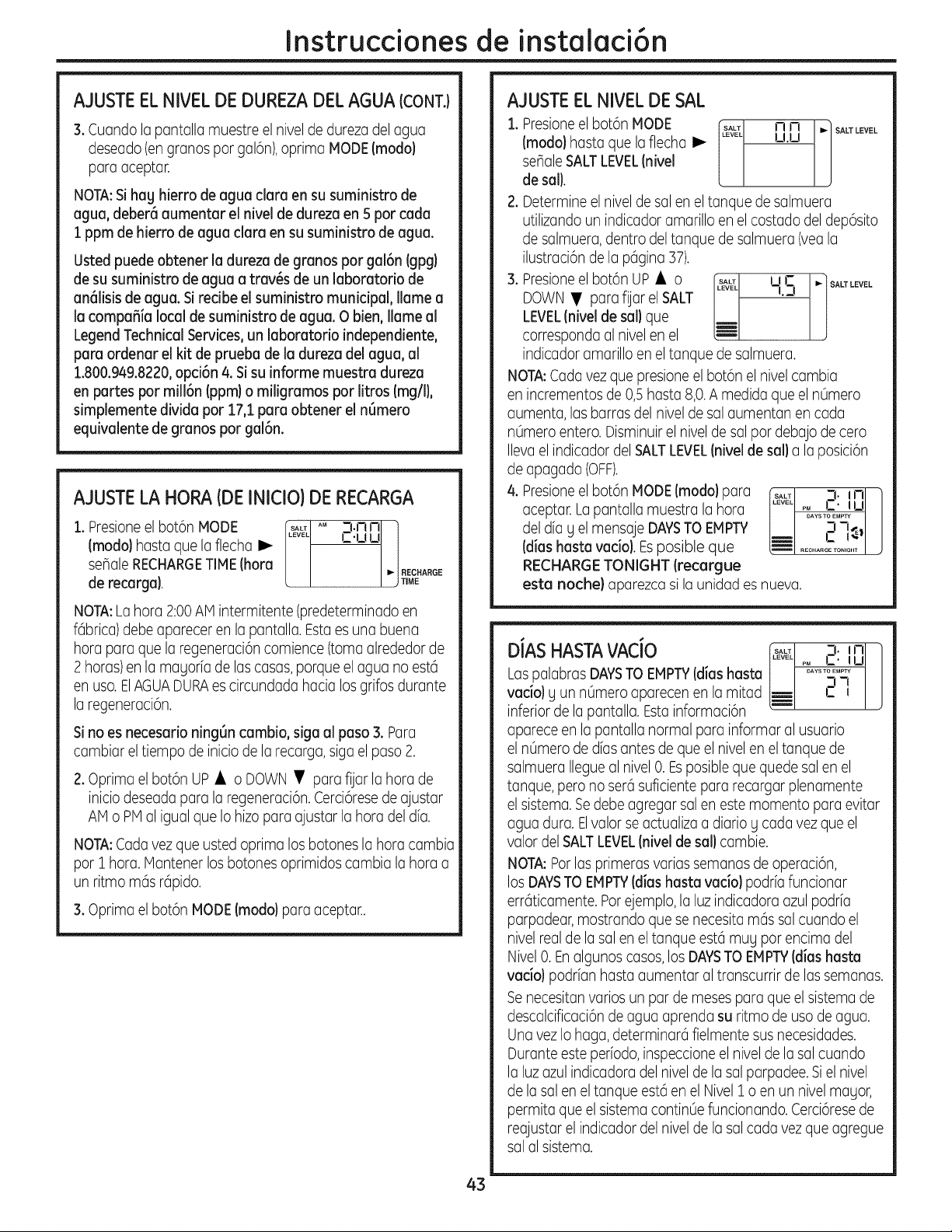
Instrucdonesde instalaci6n
AJUSTEEL NIVELDE DUREZADELAGUA (CONT.)
3. Cuandola pantallamuestre el niveldedurezadelagua
deseado(engranDspargal6n),oprimaMODE(modo}
paraaceptar.
NOTA:Si hag hierro de agua clara en susuministro de
agua,deber6 aumentar el nivel de dureza en 5 par cada
1ppm de hierro de agua clara en su suministro de agua.
Usted puede obtener la dureza de granDs par gal6n (gpg)
de susuministro de agua a trav_s de un laboratorio de
an61isisde agua.Siredbe el suministro municipal, Ilame a
la compafiia localde suministro de agua. O bien,llameal
LegendTechnicalServices, un laboratorio independiente,
para ordenar el kit de prueba de la durezadel agua,al
1.800.949.8220,opdGn 4.Sisuinforme muestra dureza
en partes par millGn (ppm) o miligramos par litros (rag/I),
simplemente divida par 17,1 para obtener el nGmero
equivalente de granDs par gal6n.
AJUSTELA HORA (DE INICIO) DE RECARGA
1.Presioneel bot6nMODE _ AM
(modalhastaquela flecha I_
seflale RECHARGETIME(hora
derecarga}.
3.nnl i
,=.uul/
I _! RECHARGE
/ j TiME
NOTA:Lahora2:00AMintermitente(predeterminadoen
fGbrica)debeapareceren lapantalla.Estaesuna buena
horaparaquela regeneraci6ncomience(tomaalrededorde
2 horas)enlamagoriadelascasas,porqueelaguano est6
en usa.ElAGUADURAescircundadahacialosgrifosdurante
la regeneraci6n.
Sino esnecesario ningGn cambio,siga al paso 3. Para
cambiar el tiempo de iniciode la recarga, sigael paso 2.
2.Oprimael bot6nUP• o DOWN • para fijarla hora de
inicio deseadapara la regeneraci6n.Cerci6resede ajustar
AMo PM al igual que Io hizo para a]ustarla hora del dfa.
NOTA:Cada vez que usted oprima los botones la hora cambia
par 1 hora.Mantener los botones oprimidos cambia la hora a
un ritmo mGsr@ido.
3.Optima el bot6nMODE(modalpara aceptar..
AJUSTEEL NIVELDE SAL
1. Presioneel bot6nMODE ft_1 n n M SALTLEVEL
(modo) hastaquela flechaI_ [ u.u J
seflaleSALTLEVEL(nivel
de sail.
2. Determineel niveldesal enel tanquedesalmuera
utilizandoun indicadoramarilloenelcostadodeldep6sito
desalmuera,dentrodeltanquedesalmuera(yeala
ilustraci6nde la pGgina37).
3. Presioneel bot6nUP• o I,_lJ ,,r ..lSALTLEVEL
DOWN • parafiat el SALT -L3
LEVEL(niveJde saJ}que
correspondaalnivelen el _-
indicadoramarilloeneltanquede salmuera.
NOTA:Cadavezquepresioneelbot6nel nivelcambia
enincrementosde0,5hasta8,0.A medidaqueel n0mero
aumenta,lasbarrasdel niveldesal aumentanencada
n0meroentero.Disminuirel niveldesal pardebajodecero
IlevaelindicadordelSALTLEVEL(nivelde saila la posici6n
de apagado (OFF).
4.Presioneel bot6nMODE(modalpara
aceptar. Lapantalla muestrala hora
deldiag elmensajeDAYSTO EMPTY
(dias hasta vacio). Esposible que
RECHARGETONIGHT (recargue
3._nl 1
-i -t_ /
estanoche)aparezcasilaunidadesnueva.
3._nl /
DJAS HASTAVACJO _s_ A_s_s:_ju/
LaspalabrasDAYSTO EMPTY(diashasta
vadoJy un nOmeroaparecenen lamitad _ t-I-J J
inferiordela pantalla.Estainformaci6n
apareceenla pantallanormalparainformaral usuario
el n0merodediasantesdequeel nivelen eltanquede
salmueraIlegueal nivel0. Esposiblequequedesalenel
tanque,perono sercisuficientepararecargarplenamente
el sistema.Sedebeagregarsolenestemomentaparaevitar
aguadura.Elvalorseactualizaa diariog cadavezque el
valordelSALTLEVEL(niveldesailcambie.
NOTA:Parlasprimerasvariassemanasdeoperaci6n,
losDAYSTOEMPTY(dias hasta racial podriafuncionar
errGticamente.Parejemplo,laluzindicadoraazulpodria
parpadear,mostrandoquesenecesitamGssalcuandoel
nivelrealde lasal enel tanqueest6mugparencimadel
Nivel0. Enalgunoscasos,los DAYSTOEMPTY(diashasta
vadol podrianhastaaumentaral transcurrirdelassemanas.
Senecesitanratios un pardemesesparaqueel sistemade
descalcificaci6ndeaguaaprendasu ritmode usadeagua.
UnavezIohaga,determinarcifielmentesusnecesidades.
Duranteesteperiodo,inspeccioneelnivelde lasal cuando
la luzazulindicadoradelniveldela sal parpadee.Siel nivel
delasaleneltanqueest6enel Nivel1 o enun nivelmayor,
permitaqueel sistemacontin0efuncionando.Cerci6resede
reajustarelindicadordelniveldelasalcadavezqueagregue
salal sistema.
43
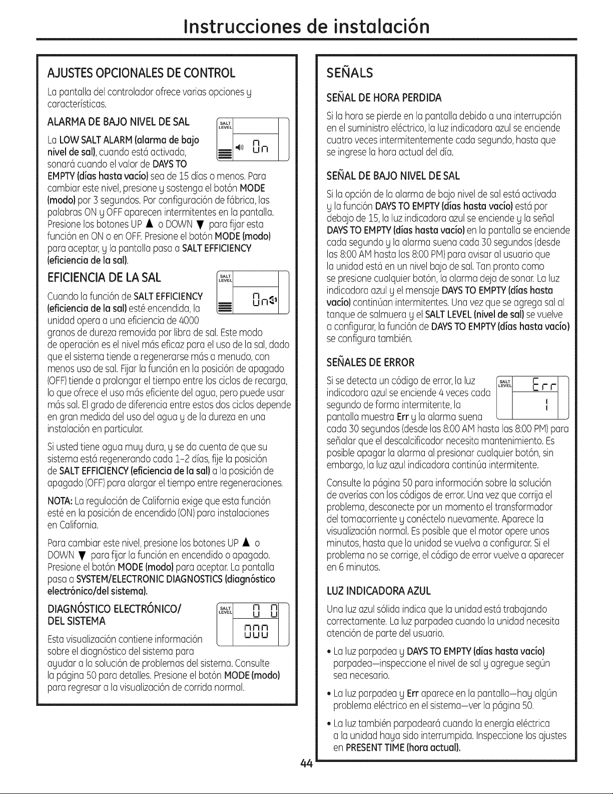
Instruccionesde instalaci6n
AJUSTESOPCIONALESDECONTROL
Lopantalladel controlador ofrece varias opciones g
caracterfsticas.
ALARMA DEBAJO NIVEL DESAL r,L_1
LaLOW SALTALARM(alarma de bajo k-- J-i
nivelde sml},cuandoest6activada, l_ 4_ u n
sonar6cuandoel valorde DAYSTO
EMPTY(dimshaste veda) seade 15 dieso menos.Para
comb(mrestenJvel,presioneg sostengaelbot6nMODE
(modo}par3 segundos.ParconfiguracJ6nde f6brica,los
palabrasON g OFF aparecenintermJtentesenlapantalla.
PresJonelosbotonesUP • o DOWN •para fijaresta
funci6n en ON o en OFF.Presioneel bot6n MODE(modo}
para aceptar, g la pantalla paso a SALTEFFICIENCY
(eficiencimde Imsal}.
EFICIENCIA DE LASAL _L ]
Cuando la funci6n de SALTEFFICIENCY J-i
(eficienciade lmsml}est6 encendida, la _- u n_ I
unidadoperaaunaeficienciade 4000
granosdedurezaremovidapar libradesal.Estemodo
deoperaci6nesel nivelm6seficazparael usadela sal,dado
queel sistematiendea regenerarsemasa menudo,con
menosusadesal.Fijarlafunci6nenla posici6ndeapagado
(OFF)tiendeaprolongarel tiempoentrelosciclosderecarga,
Ioqueofreceelusam6seficientedelagua,peropuedeusar
m6ssal.Elgradodediferenciaentreestosdosciclosdepende
engranmedidadelusadelagua g dela durezaen una
instalaci6nenparticular.
Siusted tieneagua mugdura,g se da cuenta de que su
sistema est6 regenerando cada 1-2 dias,fijela posici6n
de SALTEFFICIENCY(eficiencia de la sml}ala posici6n de
apagado (OFF)para alargar el tiempo entreregeneraciones.
NOTA:Laregulaci6ndeCaliforniaexigeque estafunci6n
est6enla posici6ndeencendido(ON)parainstalaciones
enCalifornia.
Paracambiar este nivel,presione los botones UP • o
DOWN • para fUarla funci6n en encendidoo apagado.
Presioneel bot6n MODE(modalpara aceptar. La pantalla
pasaa SYSTEMIELECTRONICDIAGNOSTICS(dimgn6stico
electr6nico/del sistemm).
DIAGNOSTICOELECTRONICO/
DELSISTEMA
Estavisualizaci6ncontieneinformaci6n
sabreel diagn6sticodelsistemapara
nnn
UUU
ayudaralasoluci6nde problemasdelsistema.Consulte
la p6gina50paradetalles.Presioneel bot6nMODE(modo}
pararegresaralavisualizaci6ndecorridanormal.
44
SERIALS
SERIALDE HORA PERDIDA
Silahora se pierde en la pantalladebido a una interrupci6n
en el suministro el6ctrico, la luz indicadoraazul se enciende
cuatro veces intermitentemente cadasegundo,hasta que
se ingrese lahora actual del da.
SERIALDEBAJO NIVEL DE SAL
Sila opci6ndela alarmadebajo niveldesalest6activada
ylafunci6nDAYSTOEMPTY(dimshmstmracial est6par
debajode 15,la luzindicadoraazulseenciendey la seBal
DAYSTOEMPTY(dimshmstmracialenla pantallaseenciende
cadasegundog la alarmasuenacada30segundos(desde
las8:00AMhastalas8:00PM)paraavisaral usuarioque
la unidadest6enun nivelbajodesal.Tanprontocoma
sepresionecualquierbot6n,la alarmadejadesonar.Laluz
indicadoraazuly el mensajeDAYSTOEMPTY(dieshastm
ratio) contin0anintermitentes.Unavezque seagregasalal
tanquede salmuerag el SALTLEVEL(niveldesml}se vuelve
a configurar,lafunci6nde DAYSTOEMPTY(dimshaste vmdo)
seconfiguratambi6n.
SERIALESDE ERROR
Sisedetectaun c6digodeerror,la luz &,_£_ c -]
indicadoraazulse enciende4 vecescada i_-.J-r
J
segundodeforma intermitente,la I
pantallamuestraErrg la alarmasuena
cada30segundos(desdelas8:00AMhastalas8:00PM)para
seBalarque el descalcificadornecesitamantenimiento.Es
posibleapagarla alarmaalpresionarcualquierbot6n,sin
embargo,la luzazulindicadoracontin0aintermitente.
Consultela p6gina50parainformaci6nsabrela soluci6n
deaveriasconlosc6digosdeerror.Unavezquecorria el
problema,desconectepar unmomentael transformador
deltomacorrienteg con6ctelonuevamente.Aparecela
visualizaci6nnormal.Esposibleque el motoropereunos
minutos,hastaquela unidadsevuelvaa configurar.Siel
problemano secorrige,el c6digodeerrorvuelvea aparecer
en6 minutos.
LUZ INDICADORA AZUL
Unaluz azul s61idaindica que la unidad est6 trabajando
correctamente.La luzparpadeacuandolaunidadnecesita
atenci6ndeportedelusuario.
• Laluzparpadeag DAYSTOEMPTY(dimshmstmveda)
parpadea-inspeccioneel niveldesalgagreguesegOn
seanecesario.
• Laluzparpadeag Errapareceenla pantalla-hag algOn
problemael6ctricoenel sistema-ver la p6gina50.
• La luztambi6n parpadear6 cuandola energfa el6ctrica
ala unidad haga sido interrumpida.Inspeccione los ajustes
en PRESENTTIME(harmmctuml).
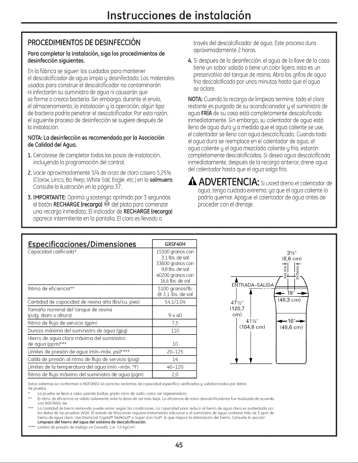
Instruccionesde instalaci6n
PROCEDIMIENTOSDE DESINFECCI6N
Parecompleter la instalaci6n, sigalosprocedimientos de
desinfecci6n siguientes.
Enlaf6bricasesiguenloscuidadosparamantener
el descalcificadordeaguelimpioydesinfectado.Losmateriales
usadospare construireldescalcificadornocontaminarGn
ni infectarGnsusuministrode aguanicausardnque
seformeo crezcabacteria.Sinembargo,duranteel envio,
el almacenamiento,la instalaci6nglaoperaci6n,alg0ntipo
debacteriapodriapenetrareldescalcificador.Parestaraz6n,
el siguienteprocesode desinfecci6nsesugieredespuGsde
la instalaci6n.
NOTA:Le desinfecci6n es recomendede par le Asocied6n
de Celided del Ague.
1. Cerci6resede completar todos los pasosde instalaci6n,
inclugendola programaci6n del control.
2.Vade aproximadamente3/4de onzade claracasero5,25%
(Clorox,Linco,BoPeep,White Sail,Eagle,etc.)en la salmuere.
Consulte la ilustraci6n en la p6gina 37.
3. IMPORTANTE:Oprimay sostengaoprimidopar 3 segundos
el bot6nRECHARGE(recerge}@delplatoparacomenzar
una recargainmediata.ElindicadordeRECHARGE(recerga}
apareceintermitenteen lapantalla.ElclaraesIlevadoa
travGsdeldescalcificadorde ague.Esteprocesodura
aproximadamente2 hares.
& SidespuGsde ladesinfecci6n,elagua de lallavede lacasa
tiene un saborsalado o tieneun colorligero,esto es un
preservativo del tanquede resina.Abra los grifos de agua
fr[a descalcificada par unosminutoshaste que el ague
se aclare.
NOTA:Cuando la recargade limpieza termine, todo elclara
restantees purgado de su acondicionador g el suministro de
agua FRIAde su casa est6 completamente descalcificada
inmediatamente.Sinembargo, sucalentador de agua est6
Ileno de agua dura g a medida que el agua caliente se use,
el calentador se Ilena conagua descalcificada. Cuando toda
el agua dura sereemplace en el calentador de agua, el
agua caliente g el agua mezcladacaliente g frfa, estarGn
completamente descalcificadas.Sidesea agua descalcificada
inmediatamente,despuGsde la recargaanterior,drene agua
del calentador hasta que el agua salgafib.
ADVERTENCIA:Siusteddrenael calentadorde
agua,tengacuidadoextremo,ga queel aguacalienteIo
podriaquemar.Apagueelcalentadordeaguaantesde
procederconel drenaje.
EspecificacioneslDimensiones
Capacidad calificada*
GXSF4OH
Ritmode eficiencia**
Cantidad de capacidad de resina alta (Ibs/cu. pies)
TamaBo nominal deltanque de resina
(pulg. diam x altura) 9 x/40
Ritmode flujo deservicio (gpm) 7,5
Dureza m6xima del suministro de agua (gpg) 110
Hierrode agua clara m6xima delsuministro
de agua (ppm)*** 10
@mitesde presi6n de agua (min-m6x. psi)**** 20-125
Caida de presi6n al ritmo deflujo de servicio (psig) 14
@mitesde la temperatura del agua (min.-m6x. °F) /40-120
Ritmode flujo m6ximo del suministro de agua (pgm) 2,0
15300 granoscon
3,1Ibs.desal
33600 granoscon
9,8Ibs.desal
40200 granoscon
16,6Ibs. desal
5100 granos/Ib.
@ 3,1 Ibs.desal
54,!/!,04
33/_/'
(8,6 cm)
2
< P-
/..,., co_-J. z _.
i __/
ENTRADA-SALIDA
_[-- -,4-- 19" ---D-
471A,, (48,3 cm)
(120,7
cm)
411/4" _ 16"'--i_
(104,8 cm) (40,6 cm)
Estos sistemas se conforman a NSF/ANSl/44 para los reclamos de capaddad espedfica verificados g substanciados par datos
de prueba.
* La prueba seIlev6 a caba usanda balitas grade clara de sadie coma sal regeneradara.
** Elritma de eficiencia esvGlida solamente ante la dosis de sal mGs baja. La eficiencia de estos descalcificadores fue evaluada de acuerdo
con NSF/ANSI4/4.
*** La cantidad de hierro removido puede variar seg0n las candicianes. La capacidad para reducir el hierro de agua clara es sustentada par
los dates de las pruebas WQA. Elestada de Wisconsin requiere tratamiento adicional siel suministro de agua cantiene rags de S ppm de
hierro de agua clara. Use Diamond Crgstal®Red,Out ®aSuper Iron Out®,Io que mejara la eliminaci6n del hierra. Consulte la secci6n
Limpieza del hierro del ague del sistema de descalcificaci6n.
**** Limites de presi6n de trabajo en Canad6:1,4-7,0 kg/cm 2.
45
Sobre el sistema de descaicificaci6n de agua.
Servicio
Cuandoelsistema descalcificadorde agua est6
proporcionando agua descalcificada, a esto sele
llama"Servicio".Durante el servicio,el agua dura
flugedesde la tuberfa de agua principalde la
casa haciaelsistema de descalcificaci6n de agua.
Enel interiordel tanque de resina del sistema de
descalcificaci6n de agua hag una pelfcula o capa
compuesta de miles de resinas plGsticasdiminutas.
Cuando elagua durapasaa tray,sdelacapa,cada
resina diminuta atrapa losminerales duros.A esto
sele llama intercambio de iones.Escoma un imGn
que atraeg atrapa metales. Luego,el agua sin
minerales duros(agua descalcificadao agua
blanda) flugehaciala casa desde el sistema de
descalcificaci6n.
Despu_s de un perfodo de tiempo,la capade
resina seobstruge o se satura conlosminerales
durosg debe limpiarse. Estalimpieza se denomina
recarga. Larecargacomienzaalas 2:00 AM
(ajustado en fGbrica)par el control del sistema
de descalcificaci6n de agua,g consiste en cinco
etapas o cicIos. EstassonFILL(llenado), BRINING
(proceso de salado), BRINERINSE(enjuague
salado), BACKWASH(lavado regresivo) UFAST
RINSE(lavador_pido).
Circunvalaci6n autom6tica del agua dura durante la recarga
Encasosde emergencia, el agua dura est6 Sin embargo, usted debe evitar usar agua
disponiblehaciala casa durante losciclosde CALIENTEporque el calentador de agua seIlenar6
recarga, conague dura.
Llenado
La sal disuelta en agua es Ilamada salmuera.La
salmuera es necesaria para limpiar los minerales
durosde las diminutas particulas de resina. Para
formar la salmuera, el agua fluye haciael interior
del tanque de salduranteel perfodo de Ilenado.
Salado
Durante el proceso de salado, la salmuera se
desplaza del area del tanque de almacenamiento
de la sal haciael tanque de la resina.Lasalmuera
es el agente de limpieza necesario para remover los
minerales durosde la capade resina.Los minerales
durosy la salmuera sondescargadoshaciael
desagOe.
La boquilla gel Venturi crean una succi6npara
mover la salmuera,manteniendo un ritmo mug
bajo para obtenerla resina de limpieza conla
menor cantidad de sal.
Enjuague de Salmuera
Despu@sde quese useuna cantidadde salmuera
medidacon anterioridad,lav(ilvulade salmuera
se cierra. Elagua contin0a flugendo en la misma
tragectoria que duranteel proceso de salado,
exceptopar el flujode salmuera discontinuado.
Los minerales durosY la salmuera flugen
del tanque de resinahaciael desagOe.
Lavado Regresivo
Durante el lavadoregresivo,el agua viajahacia
arriba a trav@sdel tanque de resina a un flujo de
ritmo rOpido,purgando el hierro acumulado,la
suciedad, y los sedimentos desdela capade
resinahaciael desagOe.
Enjuague R6pido
Ellavadoregresivo es seguidopar un flujode agua
rcipido hacia abajo a trav_sdel tanque de resina. El
flujorcipido purga la salmuera del fondo deltanque,
y rellenael tanque de resina.
A continuaci6n del enjuague rcipido,el sistema de
descalcificaciGnde agua regresa al serviciode agua
descalcificada.
46
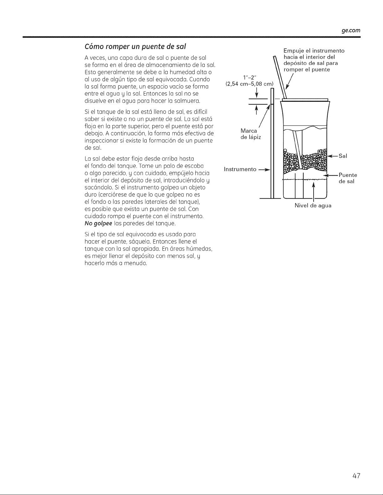
ge.com
C6mo romper un puente de sul
A veces, una capa dura de salo puente de sal
seforma en el 6rea de almacenamiento de la sal.
Esto generalmente sedebe a la humedad alta o
al uso de alg0n tipo de sal equivocada. Cuando
la sal forma puente, un espacio vacio se forma
entre el agua g la sal. Entonces la salno se
disuelve en el agua para hacer la salmuera.
Si el tanque de la sal est6 Ilenode sal, esdificil
saber siexiste o no un puente de sal. La salest6
floja en la parte superior, pero el puente est6 por
debajo. A continuaci6n, la forma m6s efectiva de
inspeccionar siexiste la formaci6n de un puente
de sal.
Empuje el instrumento
hacia el interior del
dep6sito de sal para
romper el puente
Marca
de I_piz
La saldebe estar floja desde arriba hasta
el fondo del tanque. Tome un palo de escoba
o algo parecido, g con cuidado, empOjelo hacia
el interior del dep6sito de sal, introduci_ndolo U
sac6ndolo. Si el instrumento golpea un objeto
duro (cerci6rese de que Ioque golpea no es
el fondo o las paredes laterales del tanque),
esposible que exista un puente de sal. Con
cuidado rompa el puente con el instrumento.
No golpee las paredes del tanque.
Si el tipo de sal equivocada esusado para
hacer el puente, s6quela. Entonces Ileneel
tanque con la salapropiada. En6reas hOmedas,
esmejor Ilenar el dep6sito con menos sal, g
hacerlo m6s a menudo.
Instru mento
Nivel de agua
de sal
47
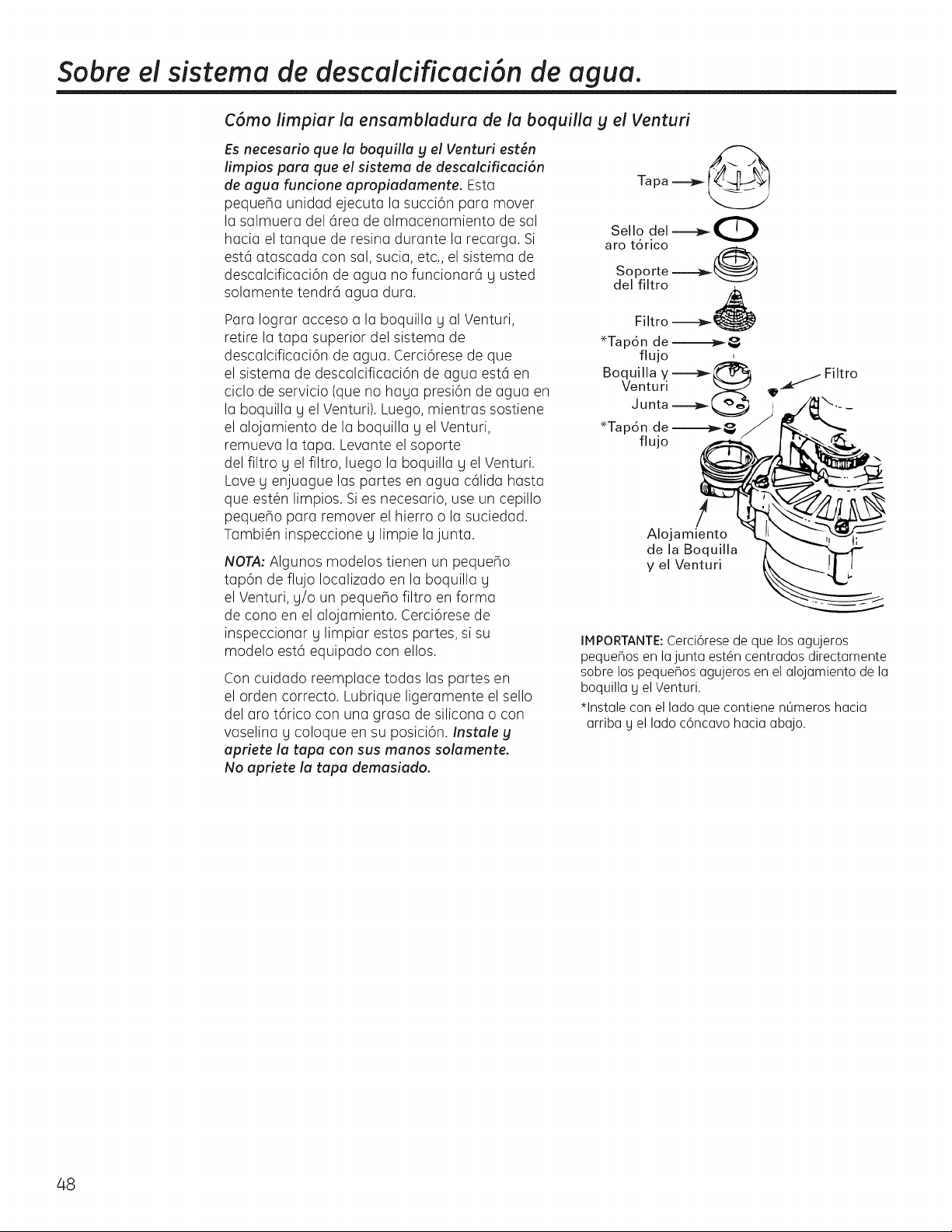
Sobre el sistema de descaicificaci6n de agua.
C6mo limpiar la ensambladura de la boquilla g el Venturi
Es necesario que la boquilla g el Venturi est6n
limpios para que el sistema de descalcificaci6n
de agua funcione apropiadamente. Esta
peque_a unidad ejecuta la succi6n para mover
la salmuera del 6rea de almacenamiento de sal
hacia el tanque de resina durante la recarga. Si
est6 atascada con sal, sucia, etc., el sistema de
descalcificaci6n de agua no funcionar6 gusted
solamente tendr6 agua dura.
Para Iograr acceso a la boquilla yal Venturi,
retire la tapa superior del sistema de
descalcificaci6n de agua. Cerci6rese de que
el sistema de descalcificaci6n de agua est6 en
ciclo de servicio (que no haya presi6n de agua en
la boquilla y el Venturi). Luego,mientras sostiene
el alojamiento de la boquilla yel Venturi,
remueva la tapa. Levante el soporte
del filtro y el filtro, luego la boquilla y el Venturi.
Lave yenjuague laspartes en agua c61ida hasta
que est@nlimpios. Si es necesario, use un cepillo
peque_o para remover el hierro o la suciedad.
Tambi@ninspeccione y limpie la junta.
NOT,4:Algunos modelos tienen un peque_o
tap6n de flujo Iocalizado en la boquilla y
el Venturi, y/o un peque_o filtro en forma
de cono en el alojamiento. Cerci6rese de
inspeccionar y limpiar estas partes, si su
modelo est6 equipado con ellos.
Concuidado reemplace todas laspartes en
el orden correcto. Lubrique ligeramente el sello
del aro t6rico con una grasa de silicona o con
vaselina g coloque en su posici6n. Instale y
apriete la tapa con sus manos solamente.
No apriete la tapa demasiado.
Tapa _
Sello del ---_0
aro tdrico
Soporte -----a_ @
del filtro
Fi Itro ----_
*Tapdn de---_,
flujo
Boquilla y _ Filtro
Venturi 9_ -_
Junta _ _.- _
!
Alojamiento
de la Boquilla
y el Venturi
IMPORTANTE: Cerci6rese de que los agujeros
pequeBos en lajunta est@ncentrados directamente
sobre los pequeBos agujeros en el alojamiento de la
boquilla g el Venturi.
*lnstale con el lado que contiene nOmeros hacia
arriba g el lado c6ncavo hacia abajo.
48
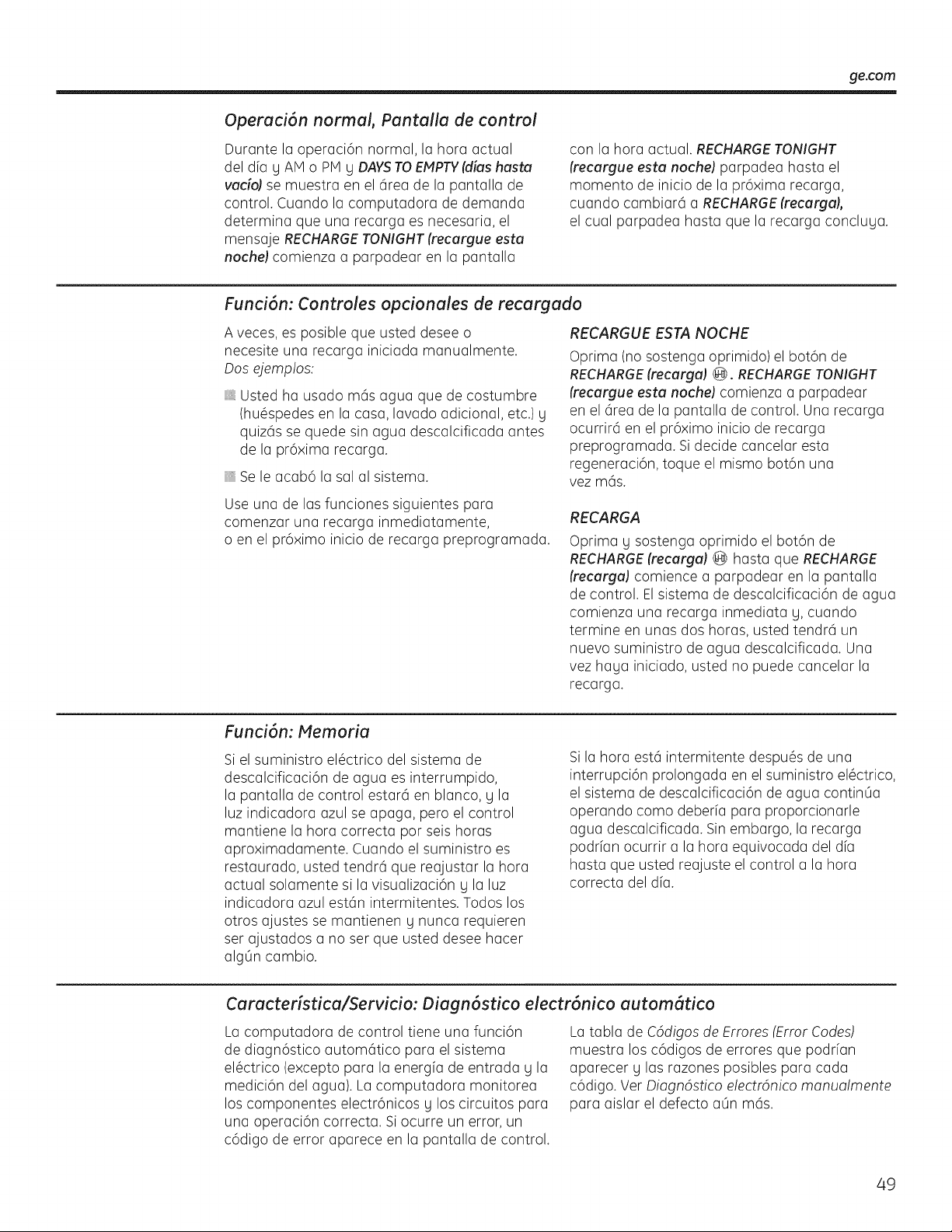
ge.com
Operaci6n normal, Pantalla de control
Durante la operaci6n normal, la hora actual
del dfa yAMo PM y DAYSTO EMPTY(dieshaste
vudoJ semuestra en el 6rea de la pantalla de
control. Cuando la computadora de demanda
determina que una recarga esnecesaria, el
mensaje RECHARGE TONIGHT (recurgue estu
noche) comienza a parpadear en la pantalla
con la hora actual. RECHARGE TONIGHT
(recargue estu noche) parpadea hasta el
momento de inicio de la pr6xima recarga,
cuando cambiar6 a RECHARGE(recargaj,
el cual parpadea hasta que la recarga concluua.
Funci6n: Controles opcionales de recargado
A veces, esposible que usted desee o
necesite una recarga iniciada manualmente.
Dos ejemp!os:
Ustedha usado m6s agua que de costumbre
(hu_spedes en la casa,lavado adicional, etc.)g
quiz6s sequede sinagua descalcificada antes
de la pr6xima recarga.
Se le acab6 la salal sistema.
Use una de lasfunciones siguientes para
comenzar una recarga inmediatamente,
o en el pr6ximo inicio de recarga preprogramada.
RECARGUE ESTANOCHE
Oprima (no sostenga oprimido) el bot6n de
RECHARGE(recarga) @. RECHARGETONIGHT
(recargue esta noche) comienza a parpadear
en el 6rea de la pantalla de control. Una recarga
ocurrir6 en el pr6ximo inicio de recarga
preprogramada. Sidecide cancelar esta
regeneraci6n, toque el mismo bot6n una
vez m6s.
RECARGA
Oprima g sostenga oprimido el botbn de
RECHARGE(recarga) @ hasta que RECHARGE
(recarga) comience a parpadear en la pantalla
de control. Elsistema de descalcificaci6n de agua
comienza una recarga inmediata g,cuando
termine en unas dos horas, usted tendr6 un
nuevo suministro de agua descalcificada. Una
vez haga iniciado, usted no puede cancelar la
recarga.
Funci6n: Memoria
Si el suministro el@ctrico del sistema de
descalcificaci6n de agua es interrumpido,
la pantalla de control estar6 en blanco, g la
luz indicadora azul seapaga, pero el control
mantiene la hora correcta pot seis horas
aproximadamente. Cuando el suministro es
restaurado, usted tendr6 que reajustar la hora
actual solamente sila visualizaci6n g la luz
indicadora azulest6n intermitentes. Todos los
otros ajustes semantienen y nunca requieren
serajustados a no ser que usted desee hacer
algOn cambio.
Si la hora est6 intermitente despu_s de una
interrupci6n prolongada en el suministro el@ctrico,
el sistema de descalcificaci6n de agua contin0a
operando como deberfa para proporcionarle
agua descalcificada. Sin embargo, la recarga
podrian ocurrir a la hora equivocada del dia
hasta que usted reajuste el control a la hora
correcta del dia.
Caracteristica/Servicio: Diagn6stico electr6nico automStico
La computadora de control tiene una funci6n
de diagn6stico autom6tico para el sistema
el@ctrico(excepto para la energfa de entrada g la
medici6n del agua). La computadora monitorea
loscomponentes electr6nicos g loscircuitos para
una operaci6n correcta. Si ocurre un error,un
c6digo de error aparece en la pantalla de control.
La tabla de C6digos de Ermres (Error Codes)
muestra losc6digos de errores que podrfan
aparecer g lasrazones posibles para cada
c6digo. Ver Diagn6stico electr6nico manualmente
para aislar el defecto a0n m6s.
49
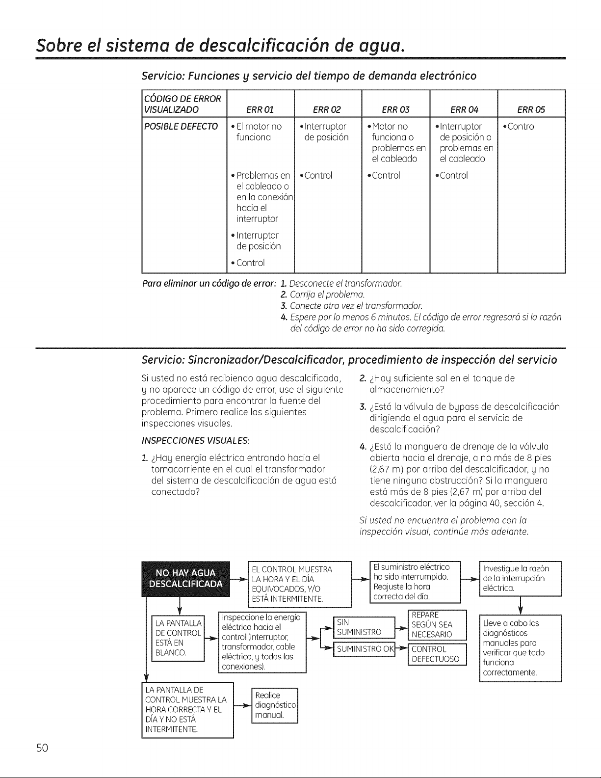
Sabre el sistema de descaicificaci6n de agua.
Servicio: Funciones g servicio de! tiempo de demanda electr6nico
CODIGODE ERROR
VISUALIZADO ERR03 ERR04 ERR05
POSIBLEDEFECTO • Control
ERR01
• El motor no
funciona
• Problemas en
el cableadoo
en la conexi6n
haciael
interruptor
• Interruptor
de posici6n
• Control
ERR02
• Interruptor
de posici6n
• Control
• Motor no
funciona o
problemas en
el cableado
,Control
• Interruptor
de posici6n o
problemas en
el cableado
• Control
Para eliminar un c6digo de error: 1. Desconectee! tmnsformador.
Z Corfija e!problema.
3.Conecteotto veze! tmnsformador.
4.Esperepar !o menos 6 minutos. E!cddigode error regresardsi!a mzdn
de! cddigode error no ha sido corregida.
Servicio: Sincronizador/Descalcificador, procedimiento de inspecci6n del servicio
Si usted no est6 recibiendo agua descalcificada, 2.
y no aparece un c6digo de error,use el siguiente
procedimiento para encontrar la fuente del
3.
problema. Primero realice los siguientes
inspecciones visuoles.
INSPECCIONES VISUALES:
1._LHayenergfa elOctrica entrando hacia el
tomacorriente en el cuol el transformador
del sistema de descalcificaci6n de agua est6
conectado?
4_
_LHoysuficiente solen el tanque de
almacenamiento?
_LEst6la v61vula de bypass de descalcificaci6n
dirigiendo el agua para el servicio de
descalcificaci6n?
_Est6 la manguera de drenaje de la v61vula
abierta hacia el drenaje, a no m6s de 8 pies
(2,67 m) par arriba del descalcificador, y no
tiene ninguna obstrucci6n? Si la manguera
est6 m6s de 8 pies(2,67m)par arriba del
descalcificador, vet la p6gina 40,secci6n 4.
Si usted no encuentra e! problema con la
inspeccidn visual, continOe mds adelante.
50
ELCONTROLMUESTRA
LA HORAY ELDiA
EQUIVOCADOS,Y/O
ESTAINTERMITENTE.
Inspeccione la energia
el_ctricahacia el
control (interruptor,
transformador, cable
el_ctrico,g todaslas
conexiones).
EIsuministroel_ctrico
ha sidointerrumpido.
Reajustelahora
correctadeldia.
SUMINISTRO OK_
H
REPARE
SEGUN SEA
NECESARIO
CONTROL
DEFECTUOSO
LA PANTALLA DE
CONTROL MUESTRA LA
HORA CORRECTAVEL
D/A Y NO ESTA
INTERMITENTE.
t_ ealice J
diagn6stico
manua.
Investiguela raz6n
de la interrupci6n
el_ctrica.
Llevea cabolos
diagn6sticos
manualespara
verificarquetodo
funciona
correctamente.
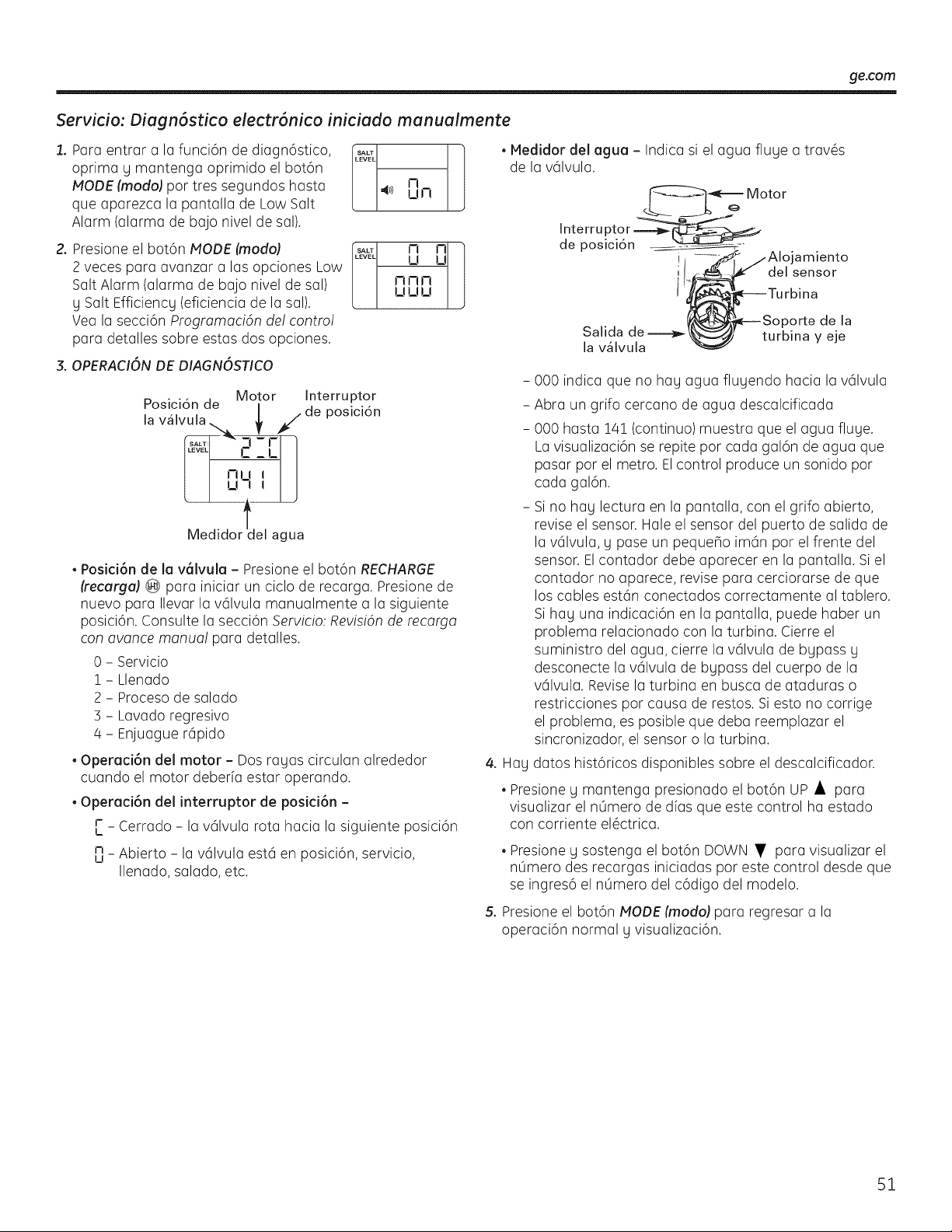
ge.com
Servicio: Diogn6stico electr6nico iniciodo monuoimente
1. Para entrar a la funci6n de diagn6stico,
oprima y mantenga oprimido el bot6n
MODE (modoJpot tres segundos hasta
que aparezca la pantalla de LowSalt
Alarm (alarma de bajo nivelde sal).
2. Presioneel bot6n MODE (modo)
2 veces para avanzar a lasopciones Low
SaltAlarm (alarma de bajo nivel de sal)
ySalt Efficiency (eficiencia de la sal).
Vea la secci6n ProgramaciOn del contro!
para detalles sobre estas dos opciones.
3.OPERACIONDE DIAGNOSTICO
SALT 1
LEVEL
41)) El !--!
p .... Motor Interruptor
oslclon de |
la v_lvula. _ _/de posicidn
C_L
?'2J
Medidortdel agua
• Posid6n de la v_lvula - Presioneel bot6n RECHARGE
(recarga} (@ para iniciar un ciclo de recarga. Presionede
nuevo para Ilevar la v61vula manualmente a la siguiente
posici6n. Consulte la secci6n Servicio:RevisiOnde recarga
conavarice manua! para detalles.
0 - Servicio
1 - Llenado
2 - Proceso de salado
3 - Lavado regresivo
4 - Enjuague r6pido
• Operaci6n del motor - Dos ragas circulan alrededor
cuando el motor deberfa estar operando.
• Operad6n del interruptor de posid6n -
r _ Cerrado - la v61vula rota hacia la siguiente posici6n
I_
m_ Abierto - la v61vulaest6 en posici6n, servicio,
u
Ilenado, salado, etc.
• Medidor del agua - Indica siel agua fluye a trav@s
de la v61vula.
Interru ptor
de posici6n
I
Motor
amiento
del sensor
Salida de
la v_lvula
)orte de la
turbina y eje
- 000 indica que no hay agua fluyendo hacia la v61vula
- Abra un grifo cercano de agua descalcificada
- 000 hasta 14! (continuo) muestra que el agua fluye.
La visualizaci6n se repite por cada gal6n de agua que
pasar por el metro. Elcontrol produce un sonido por
cada gal6n.
- Si no hay lectura en la pantalla, con el grifo abierto,
revise el sensor. Hale el sensor del puerto de salida de
la v61vula, y pase un pequeho im6n por el frente del
sensor. El contador debe aparecer en la pantalla. Si el
contador no aparece, revise para cerciorarse de que
los cables est6n conectados correctamente al tablero.
Si hay una indicaci6n en la pantalla, puede haber un
problema relacionado con la turbina. ¢ierre el
suministro del agua, cierre la v61vula de bypass y
desconecte la v61vula de bypass del cuerpo de la
v61vula. Revise la turbina en busca de ataduras o
restricciones por causa de restos. Si esto no corrige
el problema, es posible que deba reemplazar el
sincronizador, el sensor o la turbina.
4. Hay datos hist6ricos disponibles sobre el descalcificador.
• Presione g mantenga presionado el bot6n UP • para
visualizar el nOmero de dfas que este control ha estado
con corriente el_ctrica.
• Presioney sostenga el bot6n DOWN • para visualizar el
nOmerodes recargas iniciadas pot este control desde que
seingres6 el nOmerodel c6digo del modelo.
5. Presioneel bot6n t,,IODE(modo) pararegresar a la
operaci6n normal g visualizaci6n.
51
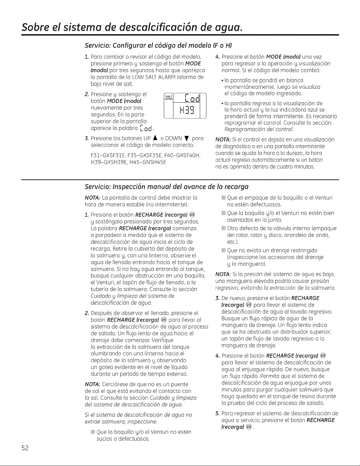
Sobre el sistema de descaicificaci6n de agua.
Servicio: Configurar el c6digo del modelo (Fo H)
2.
Para cambiar o revisor el c6digo del modelo,
presione primero y sostenga el bot6n NODE
(modoJ pot tres segundos hasta que aparezca
la pantalla de la LOW SALTALARM(alarma de
bajo nivel de sal).
Presioney sostenga el .... r 1-1
bot6n NODE (modo) ..... !_ !.3i-i
J
nuevamente pot tres Ji-_o
segundos. En la parte n Z!3
superior de la pantalla
aparece la palabra I- ad.
Presionelosbotones UP • o DOWN • para
seleccionar el c6digo de modelo correcto.
F31-GXSF31E, F35-GXSF35E, F40-GXSF40H,
H39-GXSH39E, H45-GNSH45E
4. Presioneel bot6n NODE (modo) una vez
para regresar a la operaci6n g visualizaci6n
normal. Si el c6digo del modelo cambi6:
• la pantalla sepondr6 en blanco
moment6neamente, luego sevisualiza
el c6digo de modelo ingresado.
• la pantalla regresa a la visualizaci6n de
la hora actual g la luzindicadora azul se
prender6 de forma intermitente. Esnecesario
reprogramar el control. Consulte la secci6n
Reprogramacidn de!control.
NOTA: Siel control esdejado en una visualizaci6n
de diagn6stico oen una pantalla intermitente
cuando seajusta la hora o la dureza, la hora
actual regresaautom6ticamente siun bot6n
no es oprimido dentro de cuatro minutos.
52
Servicio: Inspecci6n manual del avance de la recarga
NOTA:La pantalla de control debe mostrar la
hora de manera estable (no intermitente).
Presione el bot6n RECHARGE(recarga) @
g sost@ngalo presionado por tres segundos.
La palabra RECHARGE(recurgu) comienza
a parpadear a medida que el sistema de
descalcificaci6n de agua inicia el ciclo de
recarga. Retire la cubierta del dep6sito de
la salmuera g, con una linterna, observe el
agua de Ilenado entrando hacia el tanque de
salmuera. Si no hag agua entrando al tanque,
busque cualquier obstrucci6n en una boquilla,
el Venturi, el tap6n de fluiD de Ilenado, o la
tuberfa de la salmuera. Consulte la secci6n
Cuidado bllimpieza de!sistemo de
descalcificaci6n de agua.
2.
Despu@sde observar el Ilenado, presione el
bot6n RECHARGE(recargal ® para Ilevar al
sistema de descalcificaci6n de agua al proceso
de salado. UnfluiD lento de agua hacia el
drenaje debe comenzar. Verifique
la extracci6n de la salmuera del tanque
alumbrando con una linterna hacia el
dep6sito de la salmuera g observando
un goteo evidente en el nivel de Ifquido
durante un perbdo de tiempo extenso.
NOTA: Cerci6rese de que no esun puente
de sal el que est6 evitando el contacto con
la sal. Consulte la secci6n Cuidadog limpiezo
de!sistema de descalcificaci6n de agua.
Si e! sistema de descalcificaci6n de agua no
extrae salmuera, inspeccione:
Que la boquilla g/o el Venturi no est@n
sucios o defectuosos.
Que el empaque de la boquilla o el Venturi
no est@ndefectuosos.
,, Que la boquilla g/o el Venturi no est@nbien
asentados en la junta.
Otro defecto de la v61vula interna (empaque
del rotor, rotor y disco,arandela de onda,
etc.).
Que no exista un drenaje restringido
(inspeccione losaccesorios del drenaje
g la manguera).
NOTA: Sila presi6n del sistema de agua esbaja,
una manguera elevada podrfa causar presi6n
regresiva, evitando la extracci6n de la salmuera.
3. De nuevo, presione el bot6n RECHARGE
(recarga) @ para Ilevar el sistema de
descalcificaci6n de agua al lavado regresivo.
Busque un flujo r6pido de agua de la
manguera de drenaje. Un flujo lento indica
que seha obstruido un distribuidor superior,
un tap6n de fluiD de lavado regresivo o la
manguera de drenaje.
4. Presioneel bot6n RECHARGE(recarga) @
para Ilevar el sistema de descalcificaci6n de
agua al enjuague r6pido. Denuevo, busque
un fluiD r6pido. Permita que el sistema de
descalcificaci6n de agua enjuague por unos
minutos para purgar cualquier salmuera que
haga quedado en el tanque de resina durante
la prueba del ciclo del proceso de salado.
5. Para regresar el sistema de descalcificaci6n de
agua a servicio, presione el bot6n RECHARGE
(recarga) @.
Cuidado giimpiezadel sistema de descaicificaci6n de agua. ge.com
Inspeccione el nive! de almacenamiento de la sa! y el rellenado
Se necesita salmuera (saldisuelta en agua)
para cada recarga. Elagua para hacer la
salmuera esmedida cuando entra al 6rea de
almacenamiento de la sal a trav6s de la v61vula
del sistema de descalcificaci6n de agua g el
control. Sin embargo, usted debe mantener el
tanque con saL
Cu6ndo rellenar con sah Si una luzindicadora
azul seenciende g muestra DAYSTOEMPTY
(dias hasta vacia) parpadeando, hag menos de
!5 dfas de suministro de sal. Rellene con sal. En
6reas h0medas es mejor Ilenarcon menos sal
g hacerlo m6s frecuentemente, para evitar la
formaci6n de puentes de sal, consulte la p6gina
/47.Despu6sde agregar sal, recuerde restablecer
el SALT LEVEL(nivel de sal) en el control
(consulte la p6gina 43). Nunca permita que el
nivel de saldejar caer bajo cero en la indicadora
amarilla antes de usted rellenarlo. Sin suficiente
sal, pronto tendr6 agua dura.
Utilice sales de sistemas de descalcificaci6n
de agua solamente, pot Iomenos 99,5% puras.
Recomendamos PEPITAS,BOLITASo SALGRUESA
SOLAR.No usesal en roca, en bloques,
granulada, ni de helado (para descongelar
hielo). Estas contienen suciedad g sedimentos,
o pasta g masa, g crear6n problemas de
mantenimiento.
PRECAUCIdN:
Sal descalcificadora de agua con aditivos
que remueven el hierra: Algunas sales
podr[an tener aditivos para ayudar al
sistema de descalcificaci6n de agua con
el hierro en el suministro de agua. Aunque
este aditivo puede ayudar a mantener
limpio el sistema de descalcificaci6n de
agua, el mismo tambi6n puede crear gases
corrosivos que debilitan y acortan la vida de
las partes del sistema de descalcificaci6n de
agua. GEsolamente recomienda el uso de la
marca de sal Diamond Crystal® Red.Out ®.
C6mo limpiar el hierro de su sistema de descalcificaci6n de agua
Su sistema de descalcificaci6n de agua toma
la dureza de losmateriales (calcio g magnesio)
y la extrae del agua. Tambi6n, puede controlar
una cantidad considerable del hierro del
"agua clara" (Consultela secci6n Directrices de
especificaciones).Con hierro de agua clara, el
agua de un grifo esclara cuando secoloca en
un vaso al principio. De!5 a S0 minutos m6s
tarde, el agua comienza a ponerse turbia o a
cambiar a un color rojo ladrillo. Unsistema de
descalcificaci6n de agua no remueve el hierro
que causa queel agua setometurbia o que
adquiera el color rojo ladrillo cuando sale del
grifo (llamada agua rojo ladrillo). Para extraer
el hierro de esta agua serequiere un filtro u
otro equipo.
IMPORTANTE: Es importante mezclar el
limpiador de la capa de resinacon agua (siga
lasinstrucciones del fabricante) g vaciarlo en
el dep6sito de la salmuera (ver p6gina S7)
g proceda a regenerar el descalcificador
inmediatamente. Novierta el limpiador de la capa
de resinacon la sal, ga que no ser6tan eficiente
en su funci6n de limpieza de la resina, g puede
causar da_os al descalcificador sise deja en el
tanque de la sal pot un periodo de tiempo
prolongado debido a que gases corrosivos
seformarian.
GErecomienda que se usen lasmarcas de sal
Diamond Crgstal ®Red.Out®con aditivo Iron
Fighter® para agudar a mantener la capa de
resina limpia del hierro. Sisu suministro de agua
tiene hierro de agua clara, esnecesario que
usted limpie peri6dicamente la capa de resina.
GErecomienda usar un limpiador de capas
de resina Super Iron Out®,para limpiar asf
eficientemente dicha capa, especialmente
cuando el contenido de hierro esalto. Limpie la
capa por Iomenos cada seis meses, o m6s a
menudo sicomienza a aparecer hierro en su
agua descalcificada entre limpieza g limpieza.
53
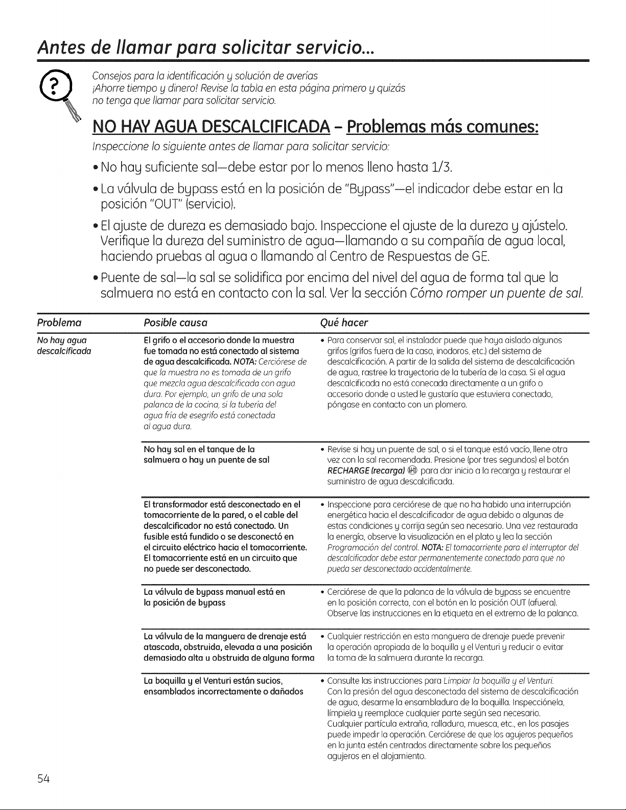
Antes de ilamar para solicitar servicio...
R
consejospara la identificaci6ny soluci6n de averias
iAhorre tiempo ydinero! Revisela tabla en esta pdgina primero y quizds
no tengaque Ilamar para solicitar servicio.
NO HAYAGUA DESCALCIFICADA- Problemas mGs comunes:
InspeccioneIo siguienteantes de Ilamar para solicitarservicio:
•No hag suficientesal-debe estar pot Io menosIlenohasta 1/S.
LavGIvuladebgpassest6 en la posici6nde "Bgpass'iel indicadordebe estar en la
posici6n"OUT"(servicio).
Elajustede durezaes demasiadobajo. Inspeccioneel ajustede la durezag ajOstelo.
Verifiquela durezadel suministrode agua-Ilamando a su compa_ia deagua local,
haciendopruebasal agua o Ilamandoal Centrode Respuestasde GE.
Puentedesal-la salse solidificapor encima del niveldel agua de forma tal que la
salmuera noest6 en contacto con la sal.Ver la secci6nC6moromper unpuentede sal.
Problema
No hag agua
descalcificada
Posible causa Ou6 hacer
Elgrifo oelaccesorio donde la muestra
fue tomada noest6 conectado al sistema
deagua descalcificada. NOTA:CerciGresede
que lamuestra no es tomada de un grifo
que mezcta agua descalcificada con agua
dura. Por ejemplo,ungrifodeuna sola
palanca dela cocina,sila tuberia del
agua ffia de esegrifo estd conectada
al aguadura.
* Para conservar sal, el instaladorpuede que hagaaislado algunos
grifos(grifosfuera dela casa,inodoros,etc.)del sistemade
descalcificaci6n. A partir de la salidadel sistema de descalcificaci6n
deagua, rastree latragectoria de la tuberia dela casa.Siel agua
descalcificada noest6 conecada directamente a ungrifo o
accesorio donde a ustedle gustaria que estuviera conectado,
p6ngaseencontacto con unplomero.
No hag sal en el tanque de la
salmuera o hag un puente de sal
Revisesi hag un puente desal,o sieltanque est6vacio,Ilene otra
vez conla sal recomendada, Presione (portres segundos)el bot6n
RECHARGE(recarga)_ para dar inicio a la recarga g restaurar el
suministro deagua descalcificada.
Eltransformador est6desconectado enel
tomacorriente de la pared,o el cable del
descalciflcador noest6 conectado. Un
fusible est6 fundido o se desconect6 en
el circuito el_ctrico hacia el tomacorriente.
Eltomacorriente est6 en uncircuito que
nopuede set desconectado.
Inspeccionepara cerci6resedeque noha habido unainterrupci6n
energ@ica hacia eldescalcificador deagua debido a algunas de
estas condiciones g corrija segOnseanecesario,Unavez restaurada
la energia,observela visualizaci6n enel plato g lea la secci6n
Programaci6ndelcontrol.NOTA:Eltomacorrientepareel interruptor del
descolcificadordebeestorpermanentementeconectodoporeque no
pueda serdesconectado accidentalmente,
La vGIvula de bgpass manual est6 en
la posici6n de bgpass
* Cerci6resedequela palancadelav61vulade bgpassse encuentre
enlaposici6ncorrecta,conelbot6nenlaposici6nOUT(afuera),
Observelasinstruccionesen laetiquetaenelextremodela palanca.
Lav61vula de la manguera dedrenaje est6 • Cualquier restricci6n en estamanguera de drenajepuedeprevenir
atascada, obstruida, elevada a una posici6n la operaci6n apropiada dela boquilla g el Venturi g reduciro evitar
demasiado alta u obstruida de alguna forma latoma de la salmuera durante la recarga.
Laboquilla g el Venturi est6n sucios,
ensamblados incorrectamente o da5ados
Consulte lasinstrucciones paraLimpiar la boquilla y el VenturL
Con la presi6ndelaguadesconectadadel sistema dedescalcificaci6n
deagua, desarme laensambladura dela boquilla,Inspecci6nela,
limpiela g reemplace cualquier parte segOnseanecesario,
Cualquier particula extraBa, ralladura, muesca, etc.,en los pasajes
puede impedir la operaci6n,Cerci6resede que losagujeros pequeBos
enlajunta est@ncentrados directamente sobrelos pequeBos
agujerosenel alojamiento.
54
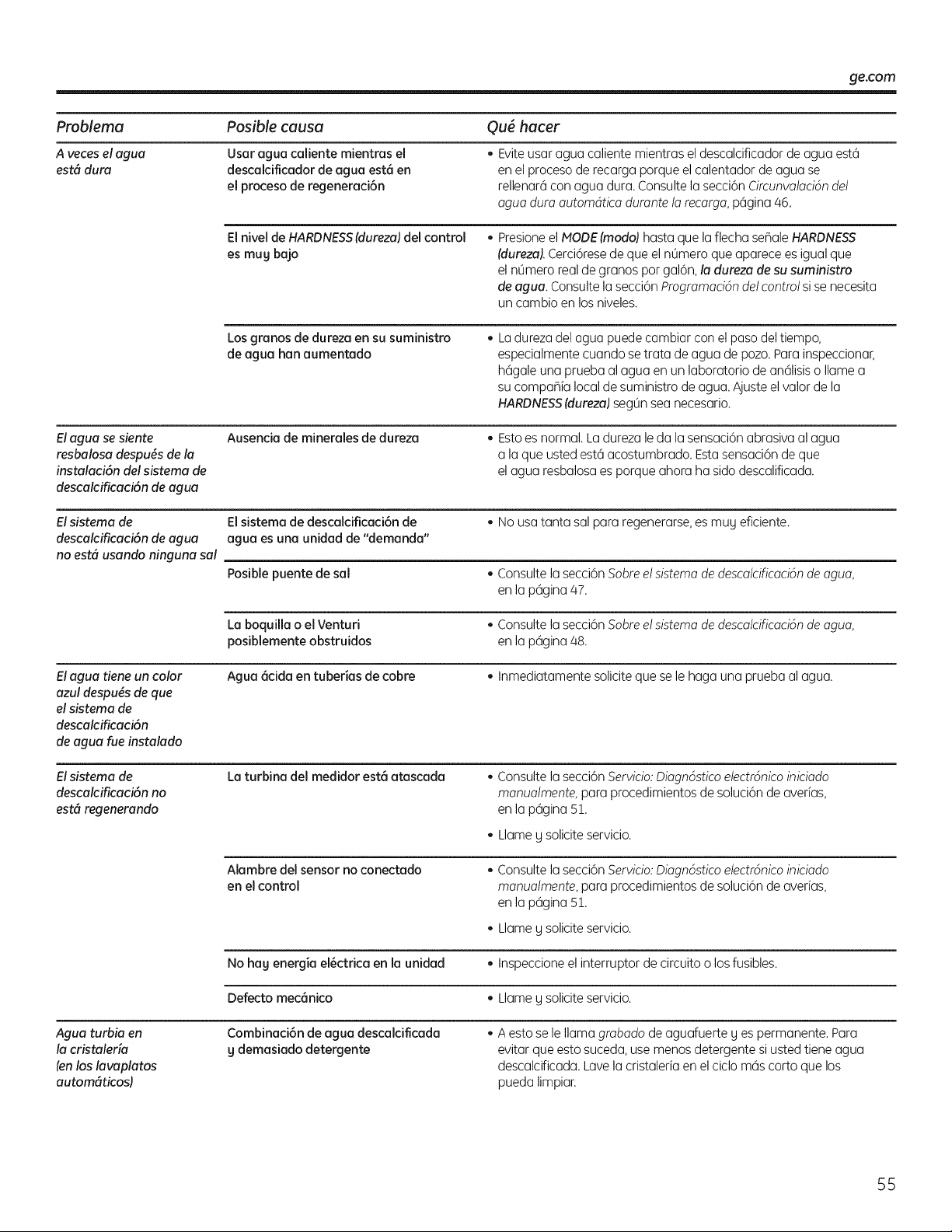
ge.com
Problema Posible causa Qu_ hacer
A vecesel agua Usaragua caliente mientras el • Evite usaraguacaliente mientraseldescalcificador deagua est6
est6 dura descalcificadorde agua est_ en enel proceso derecarga porqueel calentador deagua se
el proceso de regeneraci6n rellenar6 con agua dura. Consulte la secci6n Circunvalacidndel
aguadura automdtica durante la recarga, p6gina/46.
El nivel deHARDNESS(dureza)del control
es mug bajo
• Presioneel NODE(modo) hasta que la flecha seBale HARDNESS
fdureza).Cerci6resedeque el nOmeroque aparece es igualque
el nOmeroreal degranos por gal6n,la dureza desusuministro
deagua. Consulte la secci6n Programacidndelcontrol si se necesita
uncambio en los niveles.
Losgranos dedureza ensu suministro
deagua han aumentado
Ladurezadelaguapuedecambiarconelpasodeltiempo,
especialmentecuandosetrata de aguadepozo.Parainspeccionar,
h6galeunapruebaal agua enunlaboratoriodean61isiso Ilamea
sucompahialocaldesuministrode agua.Ajusteel valorde la
HARDNESS(dureza)segOnseanecesario.
Elagua se siente
resbalosa despu6s dela
instalaci6n delsistema de
descalcificaci6n deagua
Ausencia de minerales dedureza
Estoes normal. Ladureza le dala sensaci6n abrasiva al agua
a la que usted est6 acostumbrado. Esta sensaci6n deque
el agua resbalosa es porqueahora hasidodescalificada.
Elsistema de El sistema dedescalcificaci6n de • Nousa tanta sal para regenerarse,es mug eficiente.
descalcificaci6n deagua agua esuna unidad de"demanda"
noest6 usando ninguna sol
Posiblepuente desol • Consulte la secci6n Sobre el sistema dedescalcificacidndeagua,
enla p6gina/47.
Laboquilla o el Venturi • Consulte la secci6n Sobre el sistema dedescalcificacidndeagua,
posiblemente obstruidos enla p6gina/48.
Elagua tiene un color Agua 6cida en tuberias de cobre • Inmediatamente solicite que se lehaga una pruebaal agua.
azul despu_s de que
elsistema de
descalcificaci6n
de aguo fue instalodo
Elsistema de
descalcificaci6n no
est6 regenerando
Laturbina del medidor est6 atascada
Consulte la secci6n Servicio: Diagn6stico electr6nico iniciado
manualmente,para procedimientos desoluci6n deaverias,
enla p6gina Sl.
Llameg solicite servicio.
Alambre delsensor noconectado
enel control
Consulte la secci6n Servicio: Diagn6stico electr6nico iniciado
manualmente,para procedimientos desoluci6n deaverias,
enla p6gina Sl.
Llameg solicite servicio.
No hag energia el6ctrica enla unidad • Inspeccione el interruptor decircuito o losfusibles.
Defecto mec6nico • Llameg solicite servicio.
Agua turbia en
la cristaleria
fenlos lavaplatos
autom6ticos)
Combinaci6n deagua descalcificada
g demasiado detergente
Aestoselellamagrabadodeaguafuerteg espermanente.Para
evitarqueestosuceda,usemenosdetergentesi ustedtieneagua
descalcificada.Lavelacristaleriaen elciclom6scortoquelos
puedalimpiar.
55
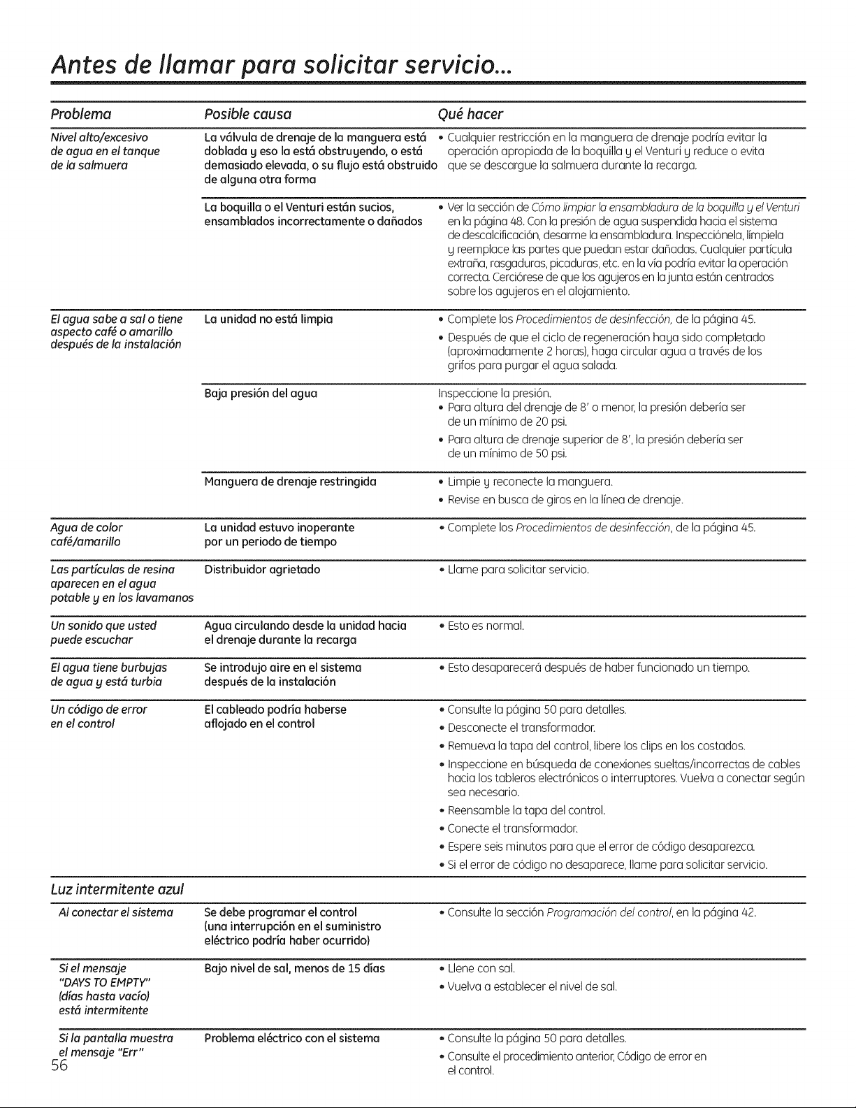
Antes de ilamar para solicitor servicio...
ProNema Posible causa Qu6 hacer
Nivelalto/excesivo La v_lvula dedrenaje de la manguera est6 • Cualquier restricci6n enla manguera dedrenajepodria evitar la
deagua enel tanque doblada g eso laest6 obstrugendo, o est6 operaci6n apropiada dela boquillag el Venturi g reduce o evita
dela salmuera demasiado elevada, o su flujo est6 obstruido que se descargue la salmuera durante la recarga.
dealguna otra forma
Elagua sabe a salo tiene
aspecto cafg o amarillo
despugs dela instalaci6n
Laboquilla o el Venturi est6n sucios,
ensamblados incorrectamente o daSados
• Verla secci6ndeC6molimpiar la ensambladuro de la boquilla yel Venturi
enla p6gina48.Conlapresi6ndeaguasuspendida hacia elsistema
dedescalcificaci6n,desarme la ensambladura. Inspecci6nela,limpiela
g reemplace los partes que puedanestar dafladas. Cualquierparticula
extrafla, rasgaduras,picaduras,etc.enla via podria evitar la operaci6n
correcta.Cerci6resede que losagujeros enlajunta est6n centrados
sobrelos agujerosenel alojamiento.
Launidad noest6 limpia Complete los Procedimientosdedesinfeccidn,dela p6gina45.
Despu6s deque el ciclo deregeneraci6n hagasidocompletado
(aproximadamente 2 horas), hagacircular aguaa trav6sdelos
grifospara purgar el agua salada.
Baja presi6n delagua Inspeccione la presi6n.
Paraaltura del drenaje de 8' o menor,la presi6ndeberiaser
deunminimo de 20psi.
Paraaltura dedrenajesuperiorde8', la presi6ndeberiaser
deunminimo de 50psi.
Hanguera de drenaje restringida • Limpie g reconecte la manguera.
Reviseenbusca degiros enla lineadedrenaje.
Agua decolor Launidad estuvo inoperante • Complete los Procedimientosdedesinfecci6n,dela p6gina45.
caf_/amarillo por un periodo detiempo
Lospardculas deresina Distribuidor agrietado • Llamepara solicitor servicio.
aparecenen elagua
potableg en loslavamanos
Un sonido que usted Aguacirculando desde la unidad hacia • Estoes normal.
puede escuchar el drenaje durante la recarga
Elagua tiene burbujas Se introdujo aire enel sistema • Estodesaparecer6 despu6s dehaber funcionado untiempo.
deagua y est6 turbia despu6s de la instalaci6n
Un c6digo deerror Elcableado podria haberse • Consulte la p6gina SOparadetalles.
enel control aflojado en el control • Desconecte el transformador.
• Remueva la tapa del control, libere losclipsenlos costados.
• InspeccioneenbOsquedadeconexiones sueltas/incorrectas decables
hacia lostableros electr6nicos o interruptores.Vuelva a conectar segOn
seanecesario.
• Reensamble la tapa del control.
• Conecte el transformador.
• Espereseisminutos para que el error dec6digodesaparezca.
• Siel errorde c6digo nodesaparece, Ilameparasolicitor servicio.
Luz intermitente azul
AI conectar el sistema
Siel mensaje
"DAYSTOEMPTY"
(dias hasta vacio)
est6 intermitente
Sila pantalla muestra
elmensaje "Err"
56
Sedebe programar el control
(una interrupci6n en el suministro
el6ctrico podria haber ocurrido}
Bajo niveldesol, menos de 15dias
• Consulte la secci6n Programaci6ndel control,enla p6gina 42.
• Llene consol.
• Vuelva a establecerel nivel desol.
Problema el6ctrico con el sistema
• Consulte la p6gina 50para detalles.
Consulteel procedimientoanterior,C6digodeerroren
elcontrol.

Notes. ge.com
57
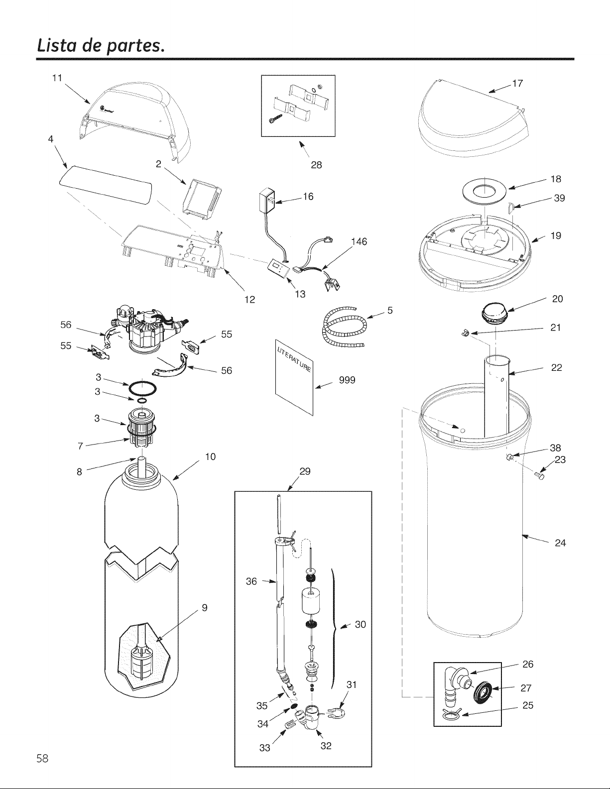
Lista de partes.
11
58
\
56
55
28
16
13
12
56
10
9
29
/
/
33 32
._j_17
19
_ 20
<__ 21
22
24
26
27
25
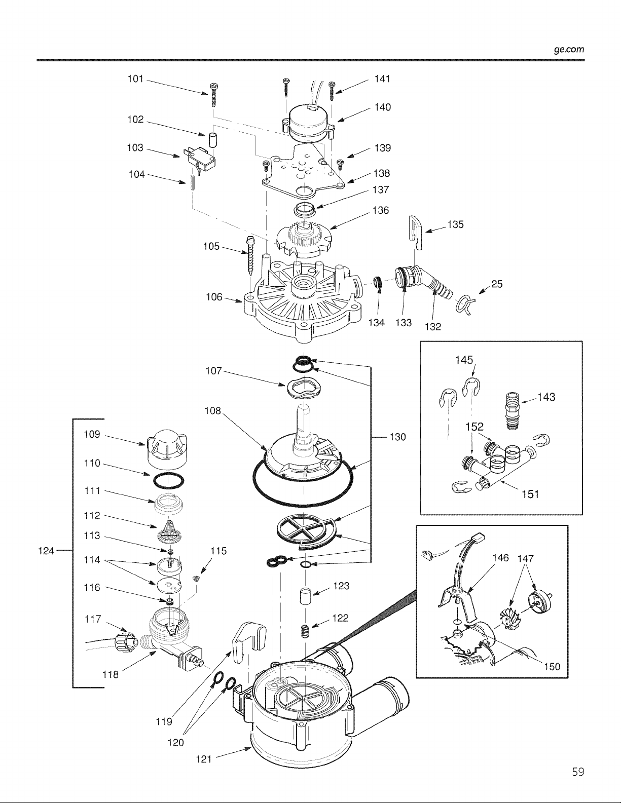
ge.com
106
_135
_.25
\
134 133 132
124_
116_
117
118
130
145
l
I
152
146 147
150
119
120
121
59
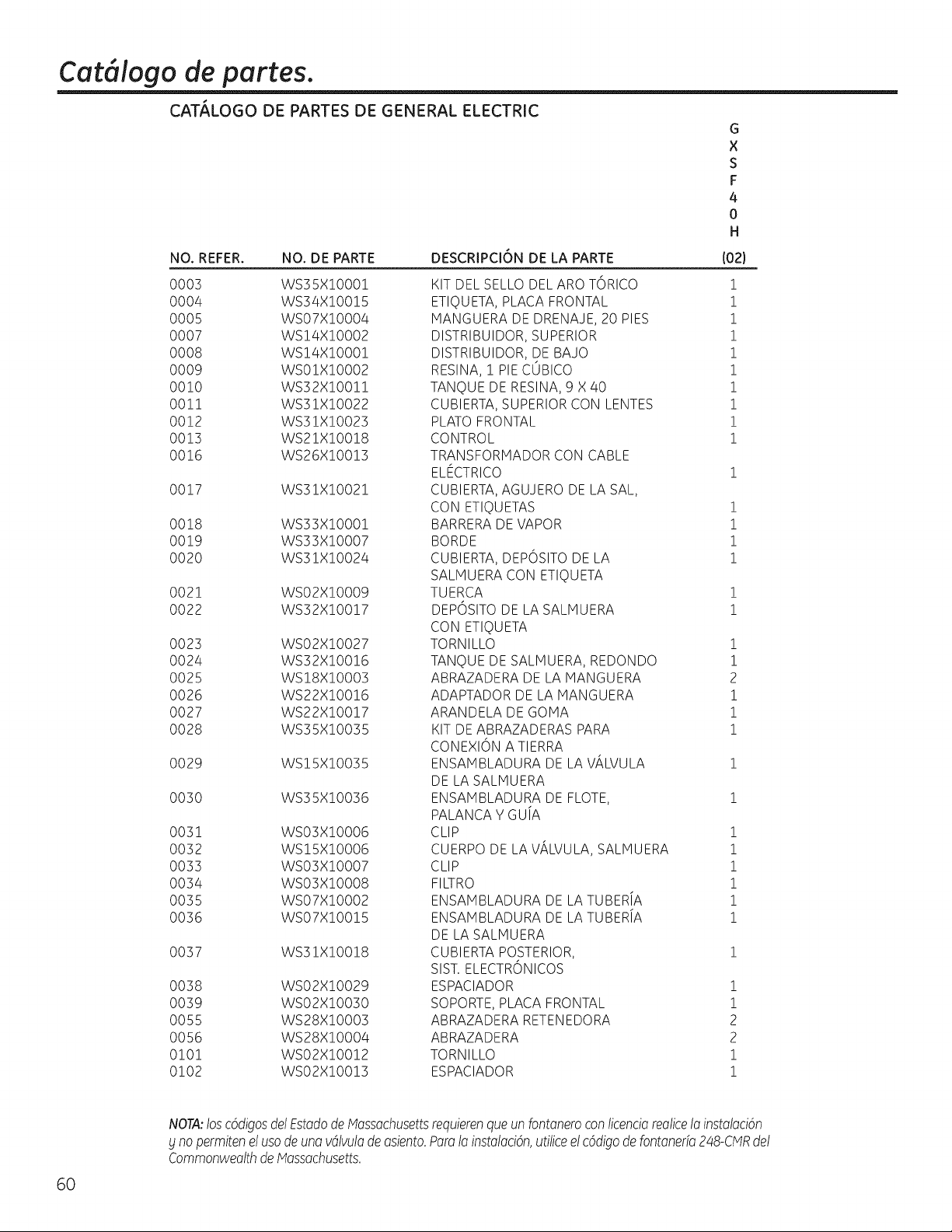
Cat, logo de partes.
CAT,_LOGO DE PARTES DE GENERAL ELECTRIC
NO. REFER. NO. DE PARTE
0003 WS35X!O001
0004 WS34X!O0!5
0005 WSO7X!O004
0007 WS!4X!O002
0008 WS!4X!O00!
0009 WSO!X!O002
00!0 WS32X!O0!!
00!1 WS3!X!O022
0012 WS3!X!O023
0013 WS2!X!O0!8
0016 WS26X!00!3
0017 WS3!X!O02!
0018 WS33X!O00!
0019 WS33X!O007
0020 WS3!X!O024
0021 WS02XI0009
0022 WS32XI0017
0023 WS02XI0027
0024 WS32X!O0!6
0025 WS!8X!O003
0026 WS22X!O0!6
0027 WS22XI0017
0028 WS35X10035
0029 WS!5X!O035
0030 WS35X!0036
0031 WSO3X!0006
0032 WS!5X!0006
0033 WSO3X!O007
0034 WSO3X!O008
0035 WSO7X!O002
0036 WSO7X!O0!5
0037 WS3!X!O0!8
0038 WSO2X!O029
0039 WSO2X!O030
0055 WS28X!O003
0056 WS28X!O004
0!0! WSO2X!O0!2
0102 WSO2X!O0!3
DESCRIPCION DE LA PARTE
G
X
S
F
4
0
H
102}
KIT DEL SELLO DELARO TORICO !
ETIQUETA, PLACA FRONTAL !
HANGUERA DE DRENAJE, 20 PIES i
DISTRIBUIDOR, SUPERIOR 1
DISTRIBUIDOR, DE BAJO i
RESINA, i PIE CUBICO i
TANQUE DE RESINA, 9 X 40 !
CUBIERTA,SUPERIOR CON LENTES i
PLATO FRONTAL i
CONTROL 1
TRANSFORHADOR CON CABLE
ELECTRICO 1
CUBIERTA,AGUJERO DE LA SAL,
CON ETIQUETAS 1
BARRERA DEVAPOR 1
BORDE 1
CUBIERTA, DEPOSITO DE LA 1
SALHUERA CON ETIQUETA
TUERCA 1
DEPOSITO DE LA SALHUERA 1
CON ETIQUETA
TORNILLO 1
TANQUE DE SALHUERA, REDONDO 1
ABRAZADERA DE LA HANGUERA 2
ADAPTADOR DE LA MANGUERA 1
ARANDELA DE GOHA 1
KIT DE ABRAZADERAS PARA 1
CONEXION A TIERRA
ENSAHBLADURA DE LAViLVULA i
DE LA SALMUERA
ENSAHBLADURA DE FLOTE, 1
PALANCA Y GUiA
CLIP 1
CUERPO DE LAViLVULA, SALHUERA 1
CLIP 1
FILTRO 1
ENSAHBLADURA DE LATUBERiA 1
ENSAMBLADURA DE LATUBERiA 1
DE LA SALHUERA
CUBIERTA POSTERIOR, 1
SIST.ELECTRONICOS
ESPACIADOR 1
SOPORTE, PLACA FRONTAL 1
ABRAZADERA RETENEDORA 2
ABRAZADERA 2
TORNILLO 1
ESPACIADOR 1
6O
NOTA:losc6digosdelEstodode Mossochusettsrequierenqueun fontoneroconticencioreolice1oinstoloci6n
£no permitenel usodeunovdlvulodeosiento.Poro1oinstoloci6n,utiliceelc6digodefontone@248-CMRdel
CommonweolthdeMossochusetts.
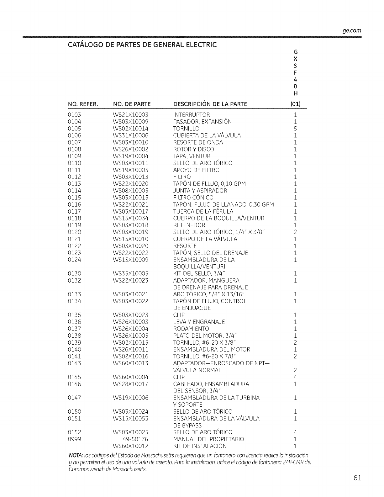
_e.com
CAT,_LOGO DE PARTES DE GENERAL ELECTRIC
G
X
S
F
4
0
H
NO. REFER. NO. DE PARTE DESCRIPCI6N DE LA PARTE (01)
0103 WS21XIO003
0104 WSO3XIO009
0105 WSO2XIO014
0106 WS31XIO006
0107 WSO3XIO010
0108 WS26XIO002
0109 WSI9XIO004
0110 WSO3XIO011
0111 WSI9XIO005
0112 WSO3XIO013
0113 WS22XIO020
0114 WSO8XIO005
0115 WSO3XIO015
0116 WS22XIO021
0117 WSO3XIO017
0118 WSI5XIO034
0119 WSO3XIO018
0120 WSO3XIO019
0121 WSISXIO010
0122 WSO3XIO020
0123 WS22XIO022
0124 WSISXIO009
0130 WS35XIO005
0132 WS22XIO023
0133 WSO3XIO021
0134 WSO3XIO022
0135 WSO3X!O023
0136 WS26X!O003
0137 WS26X!O004
0138 WS26X!O005
0139 WSO2X!O0!5
0140 WS26X!O0!!
0141 WSO2X!O0!6
0143 WS6OX!O0!3
0145 WS6OX!O004
0146 WS28X!O0!7
0147 WS!9X!O006
0150 WSO3X!O024
0151 WS!SX!O053
0152 WS03X!0025
0999 49-50176
WS60X!00!2
INTERRUPTOR !
PASADOR, EXPANSION !
TORNILLO 5
CUBIERTA DE LAViLVULA !
RESORTEDEONDA 1
ROTORY DISCO !
TAPA, VENTURI 1
SELLO DEARO TORICO 1
APOYO DE FILTRO 1
FILTRO 1
TAPON DE FLUJO,0,10 GPM 1
JUNTA Y ASPI RADOR 1
FILTROCONICO 1
TAPON, FLUJO DE LLANADO, 0,30 GPH 1
TUERCA DE LA FERULA 1
CUERPO DE LA BOQUILLA/VENTURI 1
RETENEDOR 1
SELLO DEARO TORICO, 1/4" X 3/8" 2
CUERPO DE LAVALVULA 1
RESORTE 1
TAPON, SELLO DEL DRENAJE 1
ENSAMBLADURA DE LA 1
BOQUILLA/VENTURI
KIT DEL SELLO, 3/4" 1
ADAPTADOR, MANGUERA 1
DE DRENAJE PARADRENAJE
ARO TORICO, 5/8" X 13/16" !
TAPON DE FLUJO,CONTROL 1
DE ENJUAGUE
CLIP 1
LEVA Y ENGRANAJE 1
RODAMIENTO 1
PLATO DELMOTOR, 3/4" 1
TORNILLO, #6-20 X 3/8" 2
ENSAMBLADURA DEL MOTOR 1
TORNILLO, #6-20 X 7/8" 2
ADAPTADOR--ENROSCADO DE NPT--
VALVULA NORMAL 2
CLIP 4
CABLEADO, ENSAMBLADURA 1
DEL SENSOR, 3/4"
ENSAMBLADURA DE LATURBINA !
Y SOPORTE
SELLO DEARO TORICO !
ENSAMBLADURA DE LAViLVULA !
DE BYPASS
SELLO DEARO TORICO 4
MANUAL DEL PROPIETARIO !
KIT DE INSTALACION !
NOTA:losc6digosdel EstadodeMossachusetSrequierenqueunfontoneroconticencioreolice1oinstoloci6n
_jnopermitenelusodeunovdlvulode osiento.PorotoinstolociOn,utiliceelcOdigodefontonerio248-CMRdel
CommonweolthdeMossochusetts.
61
Garantia GE para el Sistema de Descaicificaci6n de Agua.
Todos los servicios degarantia sonproporcionados pot nuestra red de
proveedores deservicios autorizados SmartWaterF Paraprogramar un
servicio, Ilame a1800.GE.CARES(800.952.5039). Cuando Ilame para
solicitar servicio, pot favor tenga a mano el nOmero de serie y el
nOmerodemodelo.
Peguesurecibo aquLLapmeba
de la fecha de la compm origina!
es necesariapare recibir e!
servicio ba]olagarantfa.
Par el periodo de:
Unoatlo
A partir de !afecha
de la compra origina!
Tresatlas
A partir de !afecha
de la compra origina!
Oiez atlas
A partir de !afecha
de la compra origina!
Reemplazamos:
Cualquierparte del Sistema de descalcificaci6n de agua que falle debido a defectos de materiales
o en lafabricaci6n. Durante esta garanda limitada de un at!o, GEtambi_n le proporcionar6,
de manera gratuita, toda lamano de obra g servicios relacionado para reemplazar partes defectuosas.
El monitor electr6nico, siel mismo falla debido a defectos de materiales oen lafabricaci6n. Durante
este periodo de tres atlas de garanda limffada, usted sere1responsable par cualquier mano de obra o
costos de servicio relacionado.
Ungabinete o tanque de salmuera de reposici6n, si cualquiera de losdos falla debido a defectos de
materiales o en la fabricaci6n. Durante este periodo de diez atlas de garantia limitada, usted sere1
responsable par cualquier mano de obra o costos de servicio relacionado.
Lo que no est6 cubierto:
mViajesde servicio a sucasa pare ense_arle c6mo usar
el producto.
Ill Reemplazo de losfusibles de la casa o reajustes de los
circuitosde interrupci6n.
m Instalaci6n, entrega omantenimiento inapropiada.
m Fallasdel producto sihag abuso, real usa, o usa para
otros prop6sitos que lospropuestos, o usapara fines
comerdales.
Ill Usa de esto producto en los sitios donde el agua es de
calidad microbiol6gicamente dudosa, ni con aguas de
calidad desconodda, sin una desinfecci6n adecuada antes o
despu_s del sistema; elsistema puede utilizarse con aguas
desinfectadas que puedan contener quistes filtmbles.
II Da_odel producto causado por acddentes, incendios,
inundaciones o incidentes de fuerza magor.
mDaSoincidental o consecuencial a la propiedad causada par
defectos posibles de este electrodom_stico, su instalaci6n
o repamci6n.
m Producto no accesible pare facilitar el serviciorequeddo.
EXCLUSION DE GARANT[AS IMPL[CITAS--Su (mica g exclusivo derecho es la reparaci6n del producto, tal g
como se indica en esta Garantia limitada. Cualquier garantia impficita, indugendo las garantias implicitas
de comerciabilidad o adecuaci6n para un fin determinado, est6n limitadas a un aria o el periodo de tiempo
m6s breve permitido par la leg.
Esta garantia se extiende al comprador original g cualquier comprador posterior de productos comprados para usa
residencial dentro de Estados Unidos. Si el producto estd situado en un drea que no dispone de servicio par parte
de un proveedor de servicio autorizado de GE, podria tenet que hacerse cargo de los castes de envio o bien podria
solicitdrsele que Ileve el producto a un centro de servicio de GE autorizado para realizar la reparaci6n. En Alaska,
la garantia excluge el costa de envio olas visitas de servicio a su casa.
Algunos estados no permiten la exclusi6n olas limitaciones de dahos incidentales o consecuenciales. Esta garantia da
derechos legales especificos, blusted podfia tenet arras derechos que variardn de estado a estado. Para saber cudles son sus
derechos legales, consulte a la oficina de asuntos del consumidor local ola oficina del Attomeg General en su Iocalidad.
Garante: General Electric Compang. Louisville, KY 40225
62
Soporte a! Consumidor.
Pdgina Web de GEAppliances
ge.com
_Tienealguna preguntasabresu electrodom@stico?iPruebela p6gina Webde GEAppliances 2/4horas
al dfa,cualquier dfa del aflo! Paramayor convenienciayserviciom6s r6pido, ya puede descargar los Manuales
de losPropietarioso pedir piezas en Ifnea.
Soliciteuna reparoci6n ge.com
Elservicio de expertos GE est6 a tan s61oun pasode supuerta. Llame al 800.GE.CARES(800./452.2757)durante
horasnormales de oficina para solicitar sureparaci6n.
RealLifeDesignStudio(Estudiode disehopara la vidareal) ge.com
GEapoga el concepto de DisehoUniversal-productos, servicios g ambientes que pueden usar gente de todas
las edades,tamahos g capacidades. Reconocemosla necesidadde diseflar para una gran gama de habilidades
g dificultades fisicas g mentales. Param6s detalles cobrelasaplicaciones de GEDiseho Universal,inclugendo
ideas de diseho para la cocina para personas condiscapacidades, mire nuestra p6gina Webhog mismo. Para
personas condificultades auditivas,favor de Ilamar al 800.TDD.GEAC(800.833./4322).
Garantiasampliadas ge.com
Compre una garantfa ampliada yobtenga detalles sabredescuentos especialesdisponibles mientras su garantfa
est6 a0n activa. Puedecomprarla en Ifneaen cualquiermomenta, o Ilamar al (800.626.2224)durante horas
normales de oficina. GEConsumer Home Servicesestar6 a0n ahfcuandosugarantfatermine.
--i Piezasblaccesorios ge.com
Aquellos individuos conla calificaci6n necesaria para reparar sus propioselectrodom@sticospueden pedir que
seles manden laspiezaso accesorios directamente a sus hogares(aceptamos las tarjetasVISA,NasterCard y
Discover).Haga supedido en I[neahoy, 24 horas cada d[a o Ilamar por tel_fono al 800.626.2002durante horas
normales de oficina.
Las instrucdones descritas en este manual cubren los procedimientos a seguir por cualquier usuano.
Cualquier otra reparad6n deberia, por regla general, refedrse a personal calificado autonzado. Debe
ejercerse precaud6n ga que las reparadones incorrectas pueden causar condidones de fundonamiento
inseguras.
P6ngase en contacto con
nosotros
Sino est6 satisfechoconel servicio que recibe de GE,p6ngaseen contacto con nosotros en nuestra p6gina
Webindicandotodos los detalles asf coma sun0merode tel@fonoo escrfbanos a:
General Manager, Customer Relations
GE Appliances, Appliance Park
Louisville, KY/40225
ge.com
"l Registresu electrodom_stico ge.com
iRegistre su nuevoelectrodom_stico en linea--cuando usted prefiera! Elregistrar suproducto a tiempo le
proporcionar6, si surgierala necesidad, una majorcomunicaciSn yun servicio m6s r6pido bajo los t_rminos de
sugarantfa. Tambi_n puede enviarsu tarjeta de registro pre-impresa que seincluye en el material de embalaje.
63

Consumer Support.
GE Appliances Website
Have a question or need assistance with yourappliance? Try theGEAppliancesWebsite 24 hoursa day,
any day of the year! For greaterconvenienceand fasterservice,you cannowdownload Owner's Hanuals
or order parts online.
ge.corrl
Schedule Service ge.com
Expert GErepair serviceis only one step away from your door. Scheduleyour service at your convenienceby
calling800.GE.CARES(800.412.2717)during normal business hours.
Real Life Design Studio ge.com
GEsupports the Universal Design concept-products, services and environments that can be used by
people ofall ages, sizesand capabilities.Werecognizethe need todesignfora wide range ofphysicaland
mental abilities and impairments. For details ofGE'sUniversal Designapplications, includingkitchendesignideas
forpeople with disabilities,checkout our Websitetoday. Forthe hearing impaired, please call800.TDD.GEAC
(800.8]].4122).
Extended Warranties
Purchasea GEextended warranty and learn aboutspecial discounts that are availablewhileyour warranty
is still in effect.You canpurchase it on-line anytime, or call 800.626.222/4during normalbusiness hours.
GEConsumerHome Serviceswillstill be thereafter yourwarranty expires.
ge.corrl
Parts and Accessories
ge.corrl
Individuals qualifiedto service theirown appliances canhaveparts or accessoriessent directlytotheir homes
(VISA,HasterCard and Discovercards are accepted).Order on-line today, 2/4hoursevery dayor
by phone at 800.626.2002during normal business hours.
Instructions contained inthis manual cover procedures to be performed bg ang user. Other servicing
generally should be referred to qualified service personnel. Caution must be exercised, since improper
servicing may cause unsafe operation.
Contact Us
If you are notsatisfiedwith theserviceyoureceive from GE,contact us on our Websitewith all the details
includingyour phone number,or write to: General Hanager, Customer Relations
GEAppliances,AppliancePark
Louisville,KY/40225
ge.corrl
Register Your Appliance
Register your newappliance on-line--at gour convenience! Timely product registrationwillallowfor
enhancedcommunication and prompt service under thetermsof yourwarranty, shouldthe need arise.
Youmay also mail inthe pre-printed registrationcard includedin thepacking material,or detach and
use theform in this Owner's Hanual.
ge.corrl
Printed in the United States

