Loading ...
Loading ...
Loading ...
6
Cold weather installations
An additional back draft damper should be installed to minimize
backward cold air ow and a thermal break should be installed
to minimize conduction of outside temperatures as part of the
vent system. The damper should be on the cold air side of the
thermal break.
The break should be as close as possible to where the vent
system enters the heated portion of the house.
Makeup air
Local building codes may require the use of makeup air systems
when using ventilation systems greater than specied CFM of
air movement. The specied CFM varies from locale to locale.
Consult your HVAC professional for specic requirements in your
area.
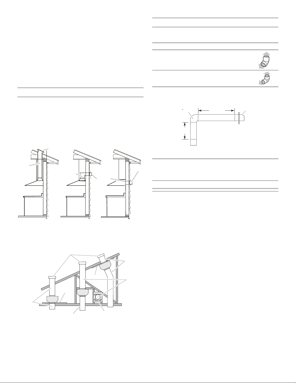
Venting Methods
Typical Internal Blower Motor System Venting Installations
A 10" (25.4 cm) round vent system is needed for installation (not
included). The hood exhaust opening is 10" (25.4 cm) round.
NOTE: Flexible vent is not recommended. Flexible vent
creates back pressure and air turbulence that greatly reduce
performance.
Vent system can terminate either through the roof or wall.
Typical In-line Blower Motor System Venting
Installations
Calculating Vent System Length
To calculate the length of the system you need, add the
equivalent feet (meters) for each vent piece used in the system.
Vent Piece Equivalent Length
45° elbow 2.5 ft
(0.8 m)
90° elbow 5.0 ft
(1.5 m)
The maximum equivalent vent lengths are:
10" (25.4 cm) round vents - 60 ft (18.3 m)
Example vent system
The following example falls within the maximum recommended
vent length.
1 - 90° elbow = 5.0 ft (1.5 m)
1 - wall cap = 0.0 ft (0.0 m)
8 ft (2.4 m) straight = 8.0 ft (2.4 m)
Length of system = 13.0 ft (3.9 m)
Electrical Requirements
Observe all governing codes and ordinances.
Ensure that the electrical installation is adequate and in
conformance with National Electrical Code, ANSI/NFPA 70
(latest edition), or CSA Standards C22.1-94, Canadian Electrical
Code, Part 1 and C22.2 No. 0-M91 (latest edition) and all local
codes and ordinances.
If codes permit and a separate ground wire is used, it is
recommended that a qualied electrician determine that the
ground path is adequate.
A copy of the above code standards can be obtained from:
National Fire Protection Association
One Batterymarch Park
Quincy, MA 02269
CSA International
8501 East Pleasant Valley Road
Cleveland, OH 44131-5575
■ A 120 V, 60 Hz, AC only, 15 A, fused electrical circuit is
required.
■ If the house has aluminum wiring, follow the procedure
below:
Connect the aluminum wiring using special connectors
and/or tools designed and UL listed for joining copper to
aluminum.
Follow the electrical connector manufacturer’s recommended
procedure. Aluminum/copper connection must conform with
local codes and industry accepted wiring practices.
■ Wire sizes and connections must conform with the rating of
the appliance as specied on the model/serial rating plate.
The model/serial plate is located behind the lter on the rear
wall of the range hood.
■ Wire sizes must conform to the requirements of the National
Electrical Code, ANSI/NFPA 70 (latest edition), or CSA
Standards C22. 1-94, Canadian Electrical Code, Part 1 and
C22.2 No. 0-M91 (latest edition) and all local codes and
ordinances.
A. Roof cap
B. 10" (25.4 cm)
round vent
A. Wall cap
B. 10" (25.4 cm)
round vent
A. Wall cap
B. 10" (25.4 cm)
round vent
A
A
B
B
B
A
F
G
D
A
A
B
C
D
A
A
H
E
A. 10" (25.4 cm) round vent
B. Mount on top of ceiling joists.
C. Roof caps
D. Plywood (optional for some installations)
E. Mount on underside of roof rafters.
F. Mount from cross-members tied to trusses.
G. Duct horizontal; mount to cross-members
tied to trusses.
H. Wall cap
90 elbow
6 ft (1.8 m)
2 ft
(0.6 m)
Wall cap
Roof venting Wall venting Wall venting
Loading ...
Loading ...
Loading ...