OPERATOR’S MANUAL
16” Cordless Chain Saw
Our Customer Service staff is ready to provide assistance.
In the case of a damaged or missing part, most replacement parts ship directly from
Merotec USA in Atlanta or from one of our service partners in the US.
For immediate help with assembly, or for additional product information, email support@
MerotecUSA.com or call 866-902-9690 M-F 8:30am – 5:00pm ET. More information can be
found on www.YardForceUSA.com.
SAVE THIS MANUAL FOR REFERENCE
You will need this manual for safety
instructions, operating procedures, and Warranty.
The original sales receipt is required for warranty service.
YF60VRX16-CS
2
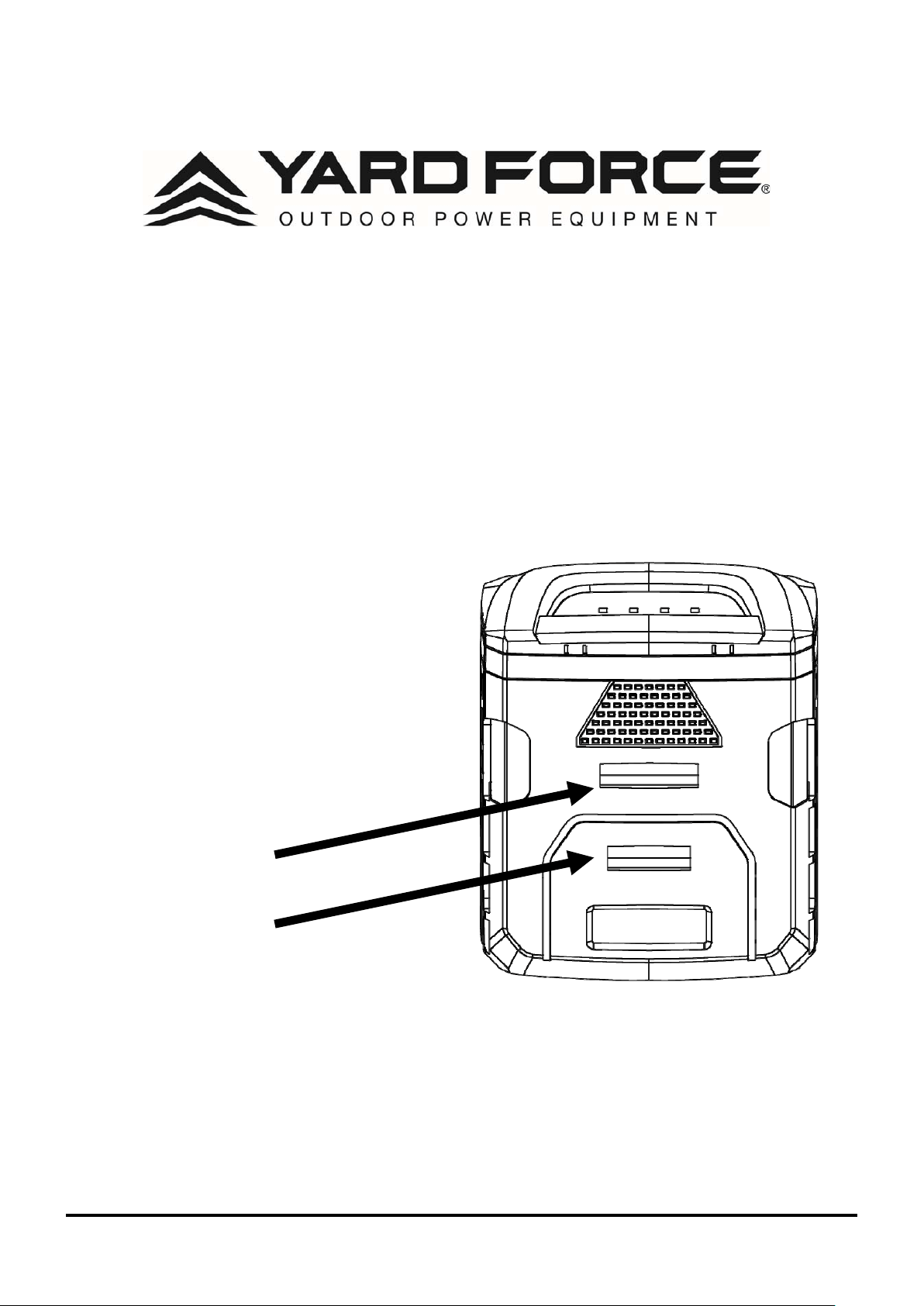
NOTICE
This YF60vRX Hand-held Tool has a
2-Step Battery Latch
INSTALLATION: The battery latch has 2 positions.
Press down firmly until battery is fully inserted. If the battery
is not fully inserted and secured in the deepest position #2
the tool will not run.
REMOVAL: Press the
release button once, the
battery will release from the
first latch position. Then hold
the battery firmly, press the
release button again and pull
battery out.
Contact our Customer Care Center
in Georgia for help with:
Product Assembly or Use
Missing Parts
Troubleshooting
866-902-9690 M-F 8:30am – 5:00pm ET
You can also visit the Yard Force USA
website to download owner’s manuals,
get product information and request
tech support.
www.YardForceUSA.com
Latch #1
Latch #2

3
4
4
11
11
11
19
21
22
TABLE OF CONTENTS
Safety Symbols.......................................................................................................................................
Safety Instructions.................................................................................................................................
Technical Data...............................................................................................................................
Description of Product...........................................................................................................................
Installation...............................................................................................................................................
Maintenance and Storage.....................................................................................................................
Troubleshooting......................................................................................................................................
Warranty......................................................................................................................................
WARNING
1. To reduce the risk of electric shock- Do not expose to water.
2. Do not use in rain. Store indoors only. Replace damaged battery pack immediately.
3. Disconnect battery pack before cleaning or servicing. Use proper eye protection. Keep away
from rotating line.
4. Do not operate without guard in place.
5. Use only 60V Li-ion battery YF60VRX4.0-BAT & YF60VRX2.5-BAT and battery charger
YF60VRX4A-CHG & YF60VRX2A-CHG.
4
READ ALL INSTRUCTIONS!
READ & UNDERSTAND
INSTRUCTION MANUAL
WARNING:
Some dust created by power
sanding, sawing, grinding, drilling and other
construction activities contains chemicals
known to the state of California to cause
cancer, birth defects or other reproductive
harm. Some examples of these chemicals
are:
•
Lead from lead - based paints
•
Crystalline silica from bricks and cement
and other masonry products, and
•
Arsenic and chromium from chemically -
treated lumber.
Your risk from these exposures varies,
depending on how often you do this type
of work. To reduce your exposure to these
chemical: work in a well ventilated area,
and work with approved safety equipment,
such as those dust masks that are
specially designed to lter out microscopic
particles. For more information go to www.
P65warnings.ca.gov.
SAFETY SYMBOLS
The purpose of safety symbols is to attract your
attention to possible dangers. The safety symbols
and the explanations with them deserve your
careful attention and understanding. The symbol
warnings do not, by themselves, eliminate any
danger. The instructions and warnings they give
are no substitutes for proper accident prevention
measures.
WARNING:
Be sure to read and understand
all safety instructions in this Operator’s
Manual, including all safety alert symbols
such as “
DANGER,
” “
WARNING,
” and
“
CAUTION
” before using this tool. Failure
to follow all instructions listed below may
result in electric shock, re, and/or serious
personal injury.
SYMBOL MEANING
SAFETY ALERT SYMBOL:
Indicates
DANGER, WARNING,
OR
CAUTION
. May
be used in conjunction with other symbols
or pictographs.
WARNING:
The operation of
any power tools can result in foreign
objects being thrown into your eyes,
which can result in severe eye
damage. Before beginning power tool
operation, always wear safety goggles
or safety glasses with side shields
and a full face shield when needed.
We recommend a Wide Vision Safety
Mask for use over eyeglasses or
standard safety glasses with side
shields. Always use eye protection
which is marked to comply with ANSI
Z87.1.
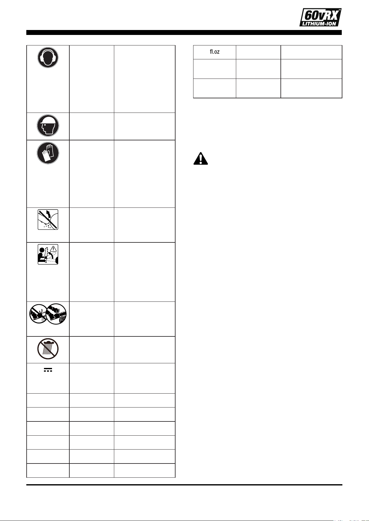
SAFETY INSTRUCTIONS
This page depicts and describes safety symbols
that may appear on this product. Read,
understand, and follow all instructions on the
machine before attempting to assemble and
operate it.
Safety Alert Indicates a
potential personal
injury hazard.
Read &
Understand
Operator's
Manual
To reduce the
risk of injury, user
must read and
understand the
operator’s manual
before using this
product.
Wear Eye
Protection
Always wear safety
goggles or safety
glasses with side
shields and a full
face shield when
operating this
product.
5
Wear Ear
Protection
Chain saw noise
may damage your
hearing. Always
wear sound
barriers (ear plugs
or ear mufers)
to protect your
hearing.
Wear Head
Protection
Wear an approved
safety hard hat to
protect your head.
Wear
Protective
Gloves
Protect your hands
with gloves when
handling saw and
saw chain. Heavy-
duty, nonslip
gloves improve
your grip and
protect your hands.
Be aware of
kickback
Contact of the
guide bar tip with
any object should
be avoided.
Guide bar tip
kickback
Tip contact can
cause the guide
bar to move
suddenly upward
and backward,
which can cause
serious injury.
Two handed
hold
Always use two
hands when
operating the chain
saw.
Be aware of
water
Do not expose or
operate the tool in
rain.
Direct
Current
Type or a
characteristic of
current
V Volt Voltage
mm Millimeter Length or size
in. Inch Length or size
kg Kilogram Weight
lb Pound Weight
ml Milliliter Volume
Fluid Ounce Volume
°C Celsius
Temperature
Temperature
°F Fahrenheit
Temperature
Temperature
GENERAL BATTERY-OPERATED
POWER TOOL SAFETY WARNINGS
WARNING
! Read all safety warnings,
instructions, illustrations and specications
provided with this power tool. Failure to
follow all instructions listed below may
result in electric shock, re and/or serious
injury.
Save all warnings and instructions for future
reference.
The term “power tool” in the warnings refers
to your mains-operated (corded) power tool or
battery-operated (cordless) power tool.
WORK AREA SAFETY
•
Keep work area clean and well lit.
Cluttered or dark areas invite accidents.
•
Do not operate power tools in explosive
atmospheres, such as in the presence of
ammable liquids, gases or dust.
Power
tools create sparks which may ignite the dust
or fumes.
•
Keep children and bystanders away while
operating a power tool.
Distractions can cause you to lose control.
PERSONAL SAFETY
•
Stay alert, watch what you are doing and
use common sense when operating a
power tool. Do not use a power tool while
you are tired or under the inuence of
drugs, alcohol or medication.
A moment of
inattention while operating power tools may
result in serious personal injury.
•
Always use personal protective
equipment.
Personal protective equipment
such as eye protection, dust mask, non-
skid safety shoes, hard hat and/or hearing
protection used for appropriate conditions
will reduce personal injuries.

6
•
Prevent unintentional starting. Ensure
the switch is in the off-position before
connecting to the battery pack, picking
up or carrying the tool.
Carrying power
tools with your nger on the switch or
energizing power tools that have the switch
on invites accidents.
•
Remove any adjusting key or wrench
before turning the power tool on.
A wrench or a key left attached to a moving
part of the power tool may result in personal
injury.
•
Do not overreach. Keep proper footing
and balance at all times.
This enables
better control of the power tool in unexpected
situations.
•
Dress properly. Do not wear loose
clothing or jewelry. Keep your hair and
clothing away from moving parts.
Loose
clothes, jewelry or long hair can be caught in
moving parts.
•
If devices are provided for the connection
of dust extraction and collection facilities,
ensure these are connected and properly
used.
Use of dust collection can reduce
dust-related hazards.
•
Do not let familiarity gained from frequent
use of tools allow you to become
complacent and ignore tool safety
principles.
A careless action can cause
severe injury within a fraction of a second.
POWER TOOL USE AND CARE
•
Do not force the power tool. Use the
correct power tool for your application.
The correct power tool will do the job
better and safer at the rate for which it was
designed.
•
Do not use the power tool if the switch
does not turn it on and off.
Any power tool
that cannot be controlled with the switch is
dangerous and must be repaired.
•
Remove the battery pack, if detachable,
from the power tool and/or activate
any battery disabling device before
clearing jammed material, making any
adjustments, changing accessories,
cleaning, or storing power tools.
Such
preventive safety measures reduce the risk
of starting the power tool accidentally.
•
Store idle power tools out of the reach
of children and do not allow persons
unfamiliar with the power tool or these
instructions to operate the power tool.
Power tools are dangerous in the hands of
untrained users.
•
Maintain power tools and accessories.
Check for misalignment or binding of
moving parts, breakage of parts and any
other condition that may affect the power
tool’s operation. If damaged, have the
power tool repaired before use. Many
accidents are
caused by poorly maintained
power tools and accessories.
•
Keep cutting tools sharp and clean.
Properly maintained cutting tools with sharp
cutting edges are less likely to bind and are
easier to control.
•
Use the power tool, accessories, tool
bits, etc. in accordance with these
instructions, taking into account the
working conditions and the work to
be performed.
Use of the power tool for
operations different from those intended
could result in a hazardous situation.
•
Keep handles and grasping surfaces
dry, clean and free from oil and grease.
Slippery handles and grasping surfaces may
lead to unsafe handling and/or loss of control
of the tool.
BATTERY TOOL USE AND CARE
•
Recharge only with the charger specied
by the manufacturer.
A charger that is
suitable for one type of battery pack may
create a risk of re when used with another
battery pack.
•
Use power tools only with specically
designated battery packs.
Use of any
other battery packs may create a risk of
injury and re.
•
When battery pack is not in use, keep it
away from other metal objects, like paper
clips, coins, keys, nails, screws or other
small metal objects, that can make a
connection from one terminal to another.
Shorting the battery terminals together may
cause burns or a re.
•
Under abusive conditions, liquid may be
ejected from the battery; avoid contact.
If contact accidentally occurs, ush with
water. If liquid contact eyes, additionally
seek medical help.
Liquid ejected from the
battery may cause irritation or burns.

7
•
Do not use a battery pack or tool that
is damaged or modied.
Damaged or
modied batteries may exhibit unpredictable
behavior resulting in re, explosion or risk of
injury.
•
Do not expose a battery pack or tool to
re or excessive temperature.
Exposure to re or temperature above 265
°F (130°C) may cause explosion.
•
Follow all charging instructions and
do not charge the battery pack or tool
outside the temperature range specied
in the instructions.
Charging improperly or
at temperatures outside the specied range
may damage the battery and increase the
risk of re.
SERVICE
•
Have your power tool serviced by a
qualied repair person using only
identical replacement parts.
This will
ensure that the safety of the power tool is
maintained.
•
Never service damaged battery packs.
Service of battery packs should only be
performed by the manufacturer or authorized
service providers.
SAFETY INSTRUCTIONS FOR CHAIN SAW
•
Keep all parts of the body away from
the saw chain when the chain saw is
operating. Before you start the chain
saw, make sure that the saw chain is
not contacting anything.
A moment of
inattention while operating chain saws may
cause entanglement of your clothing or body
with the chain.
•
Always hold the chain saw with your
right hand on the rear handle and your
left hand on the front handle.
Holding the
chain saw with a reversed hand conguration
increases the risk of personal injury and
should never be done.
•
Hold the chain saw by insulated gripping
surfaces only, because the saw chain
may contact hidden wiring.
Saw chains
contacting a “live” wire may make exposed
metal parts of the chain saw“live” and could
give the operator an electric shock.
•
Wear eye protection. Further protective
equipment for hearing, head, hands,
legs and feet is recommended.
Adequate
protective equipment will reduce personal
injury from ying debris or accidental contact
with the saw chain.
•
Do not operate a chain saw in a tree, on
a ladder, from a rooftop, or any unstable
support.
Operation of a chain saw in this
manner could result in serious personal
injury.
•
Always keep proper footing and operate
the chain saw only when standing on
xed, secure and level surface.
Slippery
or unstable surfaces may cause a loss of
balance or control of the chain saw.
•
When cutting a limb that is under tension
be alert for spring back.
When the tension
in the wood bers is released the spring
loaded limb may strike the operator and/or
throw the chain saw out of control.
•
Use extreme caution when cutting brush
and saplings.
The slender material may
catch the saw chain and be whipped toward
you or pull you off balance.
•
Carry the chain saw by the front handle
with the chain saw switched off and away
from your body. When transporting or
storing the chain saw, always t the guide
bar cover.
Proper handling of the chain
saw will reduce the likelihood of accidental
contact with the moving saw chain.
•
Follow instructions for lubricating, chain
tensioning and changing the bar and
chain.
Improperly tensioned or lubricated
chain may either break or increase the
chance for kickback.
•
Cut wood only. Do not use chain saw
for purposes not intended. For example:
do not use chain saw for cutting metal,
plastic, masonry or non-wood building
materials.
Use of the chain saw for
operations different than intended could
result in a hazardous situation.
•
Do not attempt to fell a tree until you have
an understanding of the risks and how
to avoid them.
Serious injury could occur
to the operator or bystanders while felling a
tree.
CAUSES AND OPERATOR PREVENTION OF
KICKBACK
Kickback may occur when the nose or tip of
the guide bar touches an object, or when the
wood closes in and pinches the saw chain in
the cut.
8
Tip contact in some cases may cause a
sudden reverse reaction, kicking the guide
bar up and back towards the operator.
Pinching the saw chain along the top of the
guide bar may push the guide bar rapidly
back towards the operator.
Either of these reactions may cause you
to lose control of the saw, which could
result in serious personal injury. Do not rely
exclusively upon the safety devices built into
your saw. As a chain saw user, you should
take several steps to keep your cutting jobs
free from accident or injury.
Kickback is the result of chain saw misuse
and/or incorrect operating procedures or
conditions and can be avoided by taking
proper precautions as given below:
•
Maintain a rm grip, with thumbs and
ngers encircling the chain saw handles,
with both hands on the saw and position
your body and arm to allow you to
resist kickback forces.
Kickback forces
can be controlled by the operator, if proper
precautions are taken. Do not let go of the
chain saw.
•
Do not overreach and do not cut above
shoulder height.
This helps prevent
unintended tip contact and enables better
control of the chain saw in unexpected
situations.
•
Only use replacement guide bars and saw
chains specied by the manufacturer.
Incorrect replacement guide bars and saw
chains may cause chain breakage and/or
kickback.
•
Follow the manufacturer’s sharpening
and maintenance instructions for the saw
chain.
Decreasing the depth gauge height
can lead to increased kickback.
KICKBACK SAFETY DEVICES ON
THIS CHAIN SAW CHAIN
Brake
The chain saw comes equipped with a chain
brake, which stops both the motor and
the motion of the chain when kickback occurs.
The chain brake can be activated by the forward
motion of the chain-kickback brake handle as
the saw rotates backward during kickback; it can
also be activated by the inertial forces generated
during rapid pushback.
WARNING
! Never modify or attempt to
disable the chain brake.
Make sure that the chain brake is working
properly before using the chain saw. The chain-
kickback brake handle should move back and
forth easily.
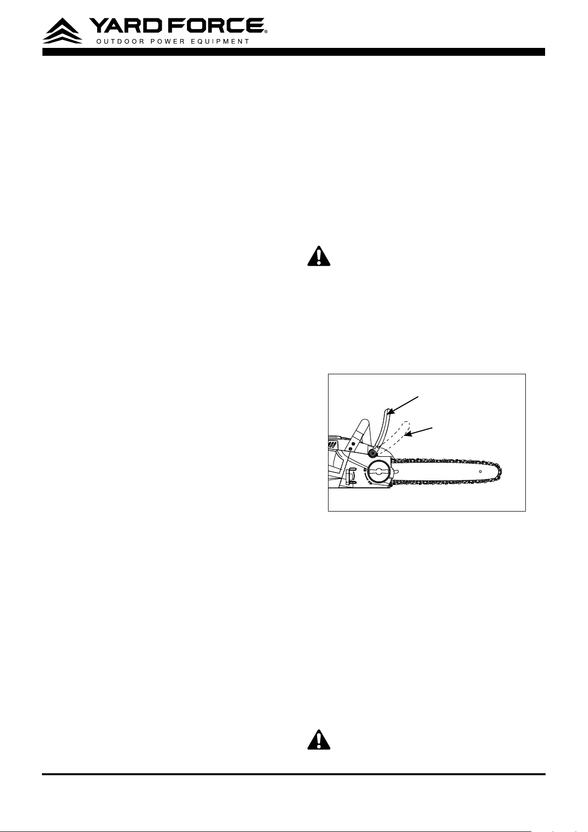
To test the operation of the chain brake perform
the following steps (Fig. 1):
Chain kickback brake
handle in operationg position
Chain kickback brake
handle in brake position
Fig.1
•
Place the chain saw on a at bare surface
and make sure no objects or obstructions
that could come in contact with the bar and
chain are in the immediate vicinity.
•
Disengage the chain brake by pulling the
chain-kickback brake handle towards the
front handle.
•
Start the chain saw.
•
Push the chain-kickback brake handle
towards the front of the saw. A properly
functioning hand brake will stop the
movement of the chain immediately. If the
chain brake is not working properly, do not
use the chain saw until it has been repaired
by a qualied service technician.
WARNING
: Conrm that the chain brake
works properly before each use.
9
WARNING
: If the chain brake is clogged
with wood chips, the function of the chain
brake may deteriorate. Always keep the
device clean.
Low Kickback Saw Chain
The ramp-shaped depth gauges ahead of each
cutter can minimize the force of a kickback
reaction by preventing the cutters from digging
in too deeply at the kickback zone. Only use
a replacement chain that is equivalent to the
original chain or has been certied as a low
kickback chain per ANSI B175.1. A low kickback
tooth saw chain is a chain that has met the
kickback performance requirements of ANSI
B175.1 (American National Standard for Power
Tools-Gasoline-Powered Chain Saws-Safety
Requirements) when tested on the representative
sample of chain saws below 3.8 c.i.d. specied in
ANSI B175.1.
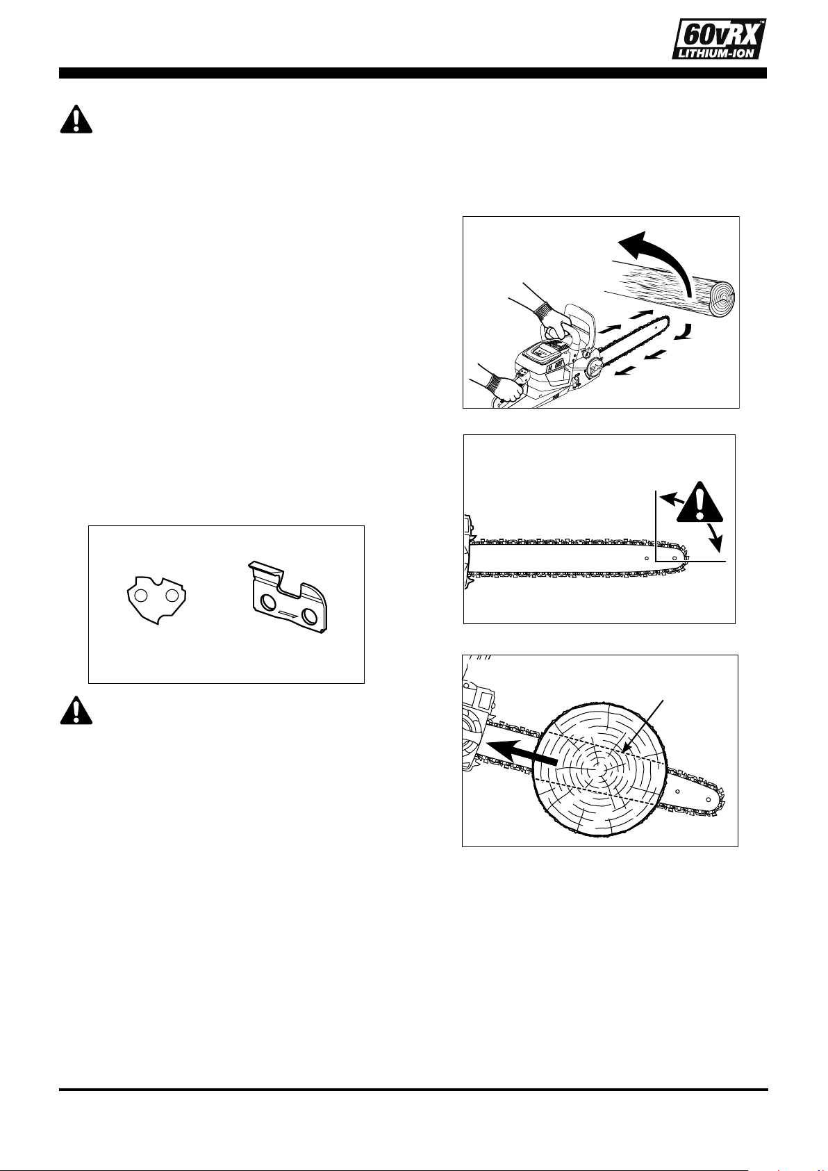
The bumper drive link (Fig. 2) also helps deliver
low-kickback performance.
Bumper drive link Cutter type
Fig.2
CAUTION:
As saw chains are sharpened
during their useful life, they lose some of
the low kickback qualities and extra caution
should be used.
GUIDE BAR
This saw comes equipped with a guide bar that
has a small radius nose. Small radius noses
generally have less potential for kickback. When
replacing the guide bar, be sure to order the bar
listed in this manual.
ADDITIONAL WARNINGS
•
With a basic understanding of kickback
(Fig. 3-5), you can reduce or eliminate
the element of surprise.
Sudden surprise
contributes to accidents.
Rotational
kickback
Fig.3
Kickback
danger zone
Fig.4
Linear kickback
Kickback
Pinch
Fig.5
•
Make sure that the area in which you are
cutting is free from obstructions.
Do not
let the nose of the guide bar contact a log,
branch, fence, or any other obstruction that
could be hit while you are operating the saw.
•
Inspect the work piece for nails, wire, or
other foreign objects prior to cutting.
•
Plan the work, ensuring an obstacle-free
work area and, in the case of felling, at
least one escape path from the falling
tree.
10
•
When felling, keep bystanders at least
two tree lengths away.
•
Keep proper footing and balance at all
times.
•
A chain saw is intended for two handed
use.
Serious injury to the operator, helpers,
and/or bystanders can result from one-
handed operation (Fig. 6).
Fig.6
•
Always cut with the unit running at full
speed.
Fully squeeze the switch trigger and
maintain cutting speed.
•
Push and Pul
l – The reaction force is
always opposite to the direction the chain is
moving where wood contact is made. Thus,
the operator must be ready to control the
PULL when cutting on the bottom edge of
the bar, and the PUSH when cutting along
the top edge (Fig. 7).
Pull
Push
Fig.7
•
Avoid unintentional contact with the
stationary saw chain or guide bar rails.
These can be very sharp. Always wear
gloves and long pants or chaps when
handling the chain saw, saw chain, or guide
bar.
•
Never operate a chain saw that is
damaged or improperly adjusted or that is
not completely and securely assembled.
Be sure that the saw chain stops moving
when the trigger switch is released.
•
When bucking, secure the work piece
prior to cutting. When felling or pruning,
identify and secure hazardous branches.
•
Aggressive or abusive cutting or misuse
of the chain saw can cause premature
bar, chain, and/or sprocket wear, as
well as a broken chain or bar, leading to
kickback, chain throw or the ejection of
material.
•
Never use the guide bar as a lever.
A bent
guide bar can cause premature bar, chain,
and/or sprocket wear, as well as a broken
chain or bar, leading to kickback, chain throw
or the ejection of material.
•
Cut only one work piece at a time.
•
Use only with the battery packs and
chargers listed below:
BATTERY PACK CHARGER
YF60VRX2.5-BAT YF60VRX2A-CHG
YF60VRX4.0-BAT YF60VRX4A-CHG
•
Do not charge the battery pack in rain or
in wet locations.
•
If situations occur which are not covered
in this manual, use care and good
judgment. Contact Customer Service for
assistance.
SAVE THESE INSTRUCTIONS!
11
TECHNICAL DATA
Model YF60VRX16-CS
Nominal voltage of
product with battery
60V
Chain speed 33 ft./s
Cutting length 16 in.(400 mm)
Chain type 90PX056X
Guide bar type 164MLEA041
Weight 17 lbs
Battery pack Model
YF60VRX2.5-BAT
Battery capacity 60 V DC, 2.5 Ah
Battery charger Model
YF60VRX2A-CHG
Input 100–240 V~, 50/60 Hz,
150 W
Output 63 V d.c., 2.5 A
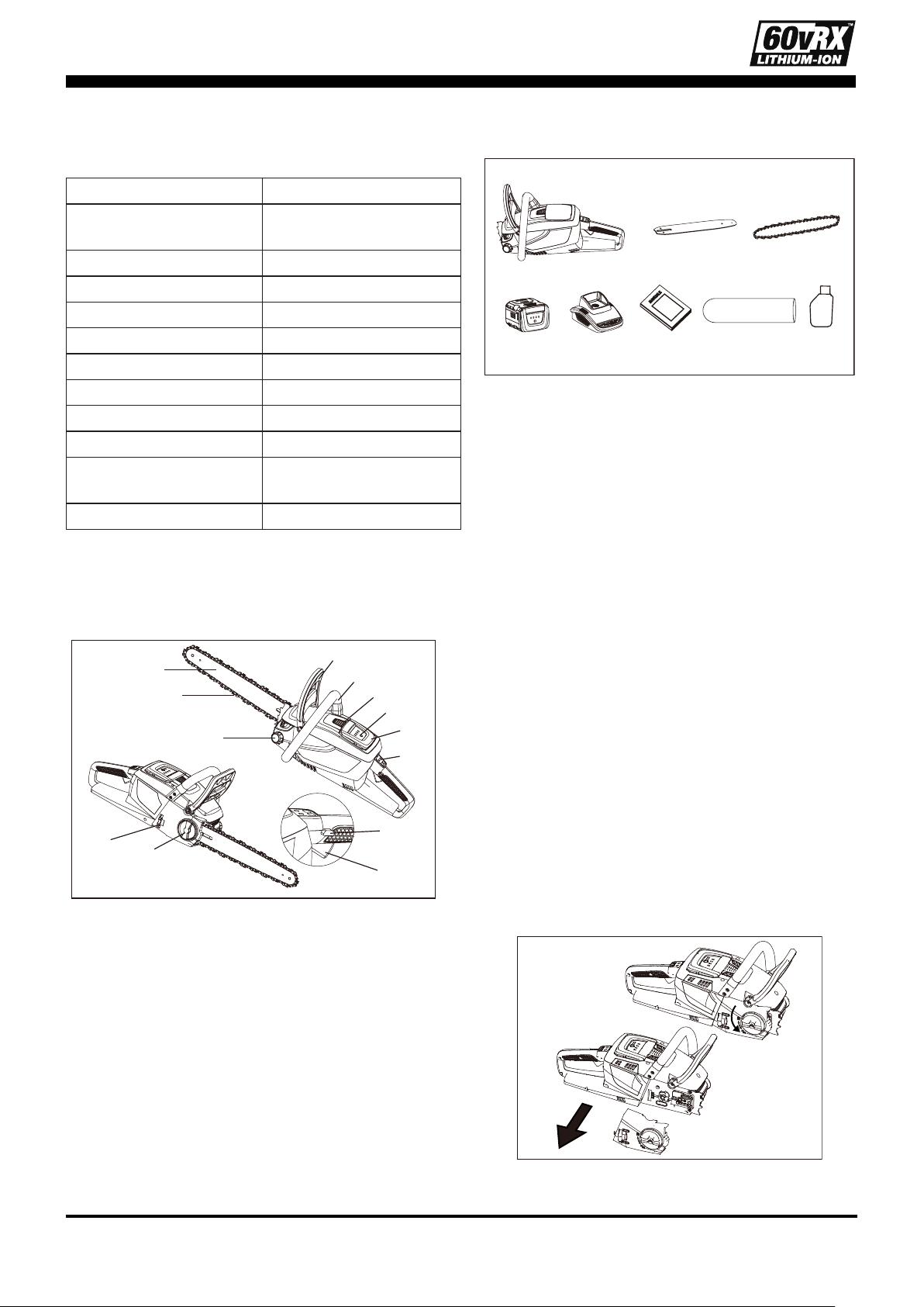
DESCRIPTION OF PRODUCT
Parts description (Fig. 8)
1
2
3
4
5
6
7
8
9
10
11
13
12
Fig.8
1. Front guard / chain brake
2. Guide bar
3. Saw chain
4. Oil tank cap
5. Indicator panel
6. Chain tension knob
7. Lock knob
8. Main switch
9. Lock- off button
10. Battery pack
11. Front handle
12. Power indicator button
13. Battery releasing/locking button
Check the delivery parts (Fig. 9)
a
cb
d e f g h
Fig.9
Remove the machine from its packaging carefully
and make sure that all of the following parts are
present:
a. Chain saw (assembled) x 1
b. Guide bar (assembled) x 1
c. Saw chain (assembled) x 1
d. Battery pack x 1
e. Charger x 1
f. Manual x 1
g. Guide bar cover x 1
h. Bar and chain lubricant oil x 1
INSTALLATION
Install the guide bar and saw chain
The bar and the saw chain of this model are
already assembled,please do as following
instruction when you need to change them.
1. Position the chain saw power head on its
side with the side cover facing upwards.
2. Turn the side cover knob anti-clockwise to
remove the side cover and then loosen the
chain tensioning knob as much as possible.
(Fig. 10)
Fig.10
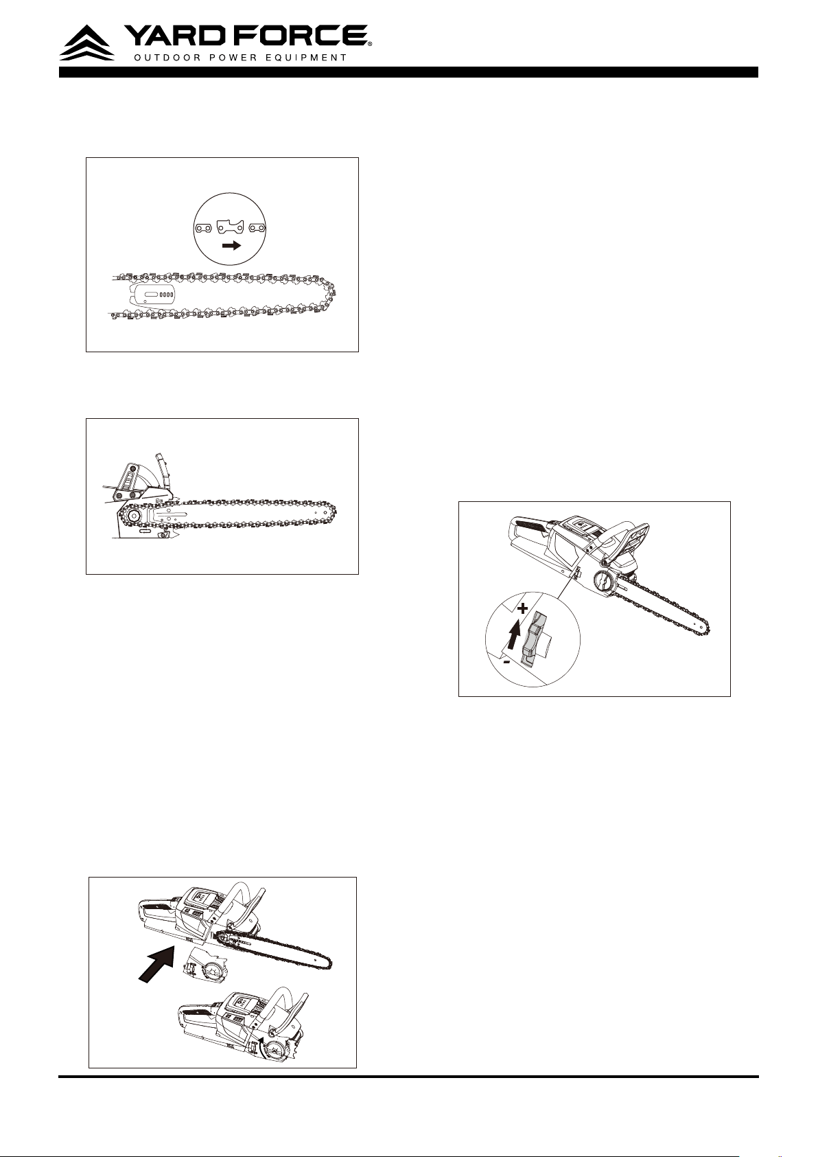
3. Lay the new saw chain in a loop on a at
surface and straighten any kinks.
12
4. Place the chain drive links into the guide bar
groove and make the chain a loop at the
back of the guide bar. (Fig.11)
Fig.11
5. Hold the chain in position on the guide bar
and place the loop around the sprocket of
the power head. (Fig. 12)
Fig.12
6. Slide the guide bar slot over the alignment
anges until the tension adjusting pin is
inserted in the lower hole in the tail of the
bar.
NOTE:
Small directional arrows are engraved
in the saw chain. Another directional arrow is
molded into the housing. When looping the
saw chain onto the sprocket, make sure that
the direction of the arrows on the saw chain will
correspond to the direction of the arrow on the
housing. If they face in opposite directions, turn
over the saw chain and guide bar assembly.
7. Replace the side cover and slightly tighten
the side cover knob.(Fig. 13)
Fig.13
8. Lift the tip of the guide bar up to check for
sag. Release the tip of the guide bar and
turn the chain tensioning knob clockwise.
Repeat this process until the sag is
eliminated.
9. Tighten the side cover knob securely to
ensure that the saw chain is properly
tensioned before using.
NOTE:
If chain is too tight, it will not rotate.
Loosen the side cover knob slightly and turn the
tensioning knob once from right to left. Lift the tip
of the guide bar up and retighten the side cover
knob securely. Assure that the chain will rotate
without binding.
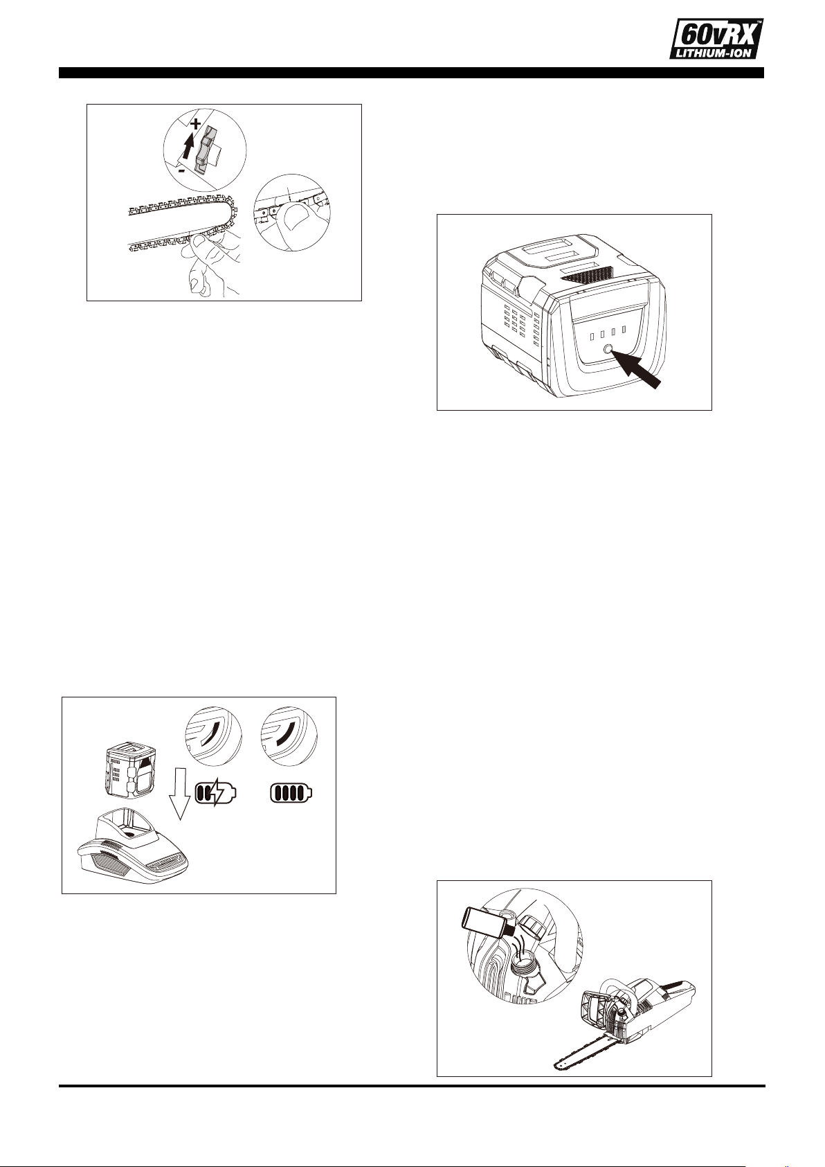
Adjusting the chain tension
- Stop the motor and remove the battery pack
before adjusting the chain tension. Make
sure the side cover knob is loosened. Turn
the chain tensioning knob clockwise to
tension the chain. (Fig. 14)
+
-
Fig.14
- A cold chain is correctly tensioned when
there is no slack on the underside of the
guide bar and the chain is snug, but it can
be turned by hand without binding. The
chain must be re-tensioned whenever the
ats on the drive links do not sit in the bar
groove.
- During normal saw operation, the
temperature of the chain will increase. The
drive links of a correctly tensioned warm
chain will hang approximately 0.08" (2 mm)
out of the bar groove (Fig. 15).
13
0.08" (2 mm)
+
-
Fig.15
NOTE:
New chains tend to stretch; check chain
tension frequently and tension as required.
NOTE:
A chain tensioned while it is warm may
be too tight upon cooling. Check the cold tension
before next use.
Charging the battery pack
NOTE:
Remove the battery pack from the
charger after it has been fully charged.
NOTE:
Battery should be fully charged before
rst use.
NOTE:
Make sure the mains voltage is the
same as the rating label which is located on the
charger.
1. Connect the charger to a power supply. The
red LED will light up.
2. To insert the battery pack into the charger,
align the raised ribs of the battery pack with
the grooves of the charger then push it in.
(Fig. 17)
Fig.17
3. The green LED light of the charger will ash
continuously during normal charging.
4. After charging is complete, the charger light
will turn to a solid green light.
Power indicator (Fig. 18)
This Li-Ion battery pack is equipped with a power
indicator which is used to show the battery packs
remaining charge. Press the power indicator
button to check battery charge as below. The
LEDs will stay lit for approximately 4 seconds.
Fig.18
To obtain the best life from the battery
NOTE:
1. Never allow the battery to completely
discharge before recharging. The battery
pack should be placed on the charger
whenever the battery pack is noticeably
running down or the tool no longer performs
a task it previously performed.
2. Avoid conducting short charges. Make sure
that the battery is fully charged each time
by allowing the charger to complete its full
charging cycle.
3. Avoid allowing loose items like screws or
nails etc. to be stored with battery packs
as these or similar items can short battery
packs' life and cause a re or explosion.
4. Always unplug the charger when not in use
and store in a dry and secure place.
5. Avoid charging or storing your battery in
temperatures below 41°F and above 113°F.
6. After use, allow the battery pack to cool
down for approximately 30 minutes before
attempting to recharge.
Filling bar and chain lubricant oil (Fig. 16)
Fig.16
14
WARNING
: Do not smoke or bring any re
or ame near the oil or the chain saw. Oil
may spill and cause a re.
NOTE:
The chain saw is not lled with oil at the
time of purchase. It is essential to ll the tank
with oil before use.
The chain is automatically lubricated with chain
oil during operation.
1. Position the chain saw on its side with its oil
tank cap facing towards.
2. Clean the cap as well as the area around
and then turn it anti-clockwise to remove.
3. Carefully pour the specically designed oil
into the tank until reaching the bottom of the
lter neck.
4. Wipe off any excessive oil and replace the
cap.
NOTE:
With upright position, oil should ll the
inspection window. When the oil is no longer
visible in the inspection window, stop use
immediately and rell.
Inserting and removing the battery pack
NOTE:
Hold the tool and the battery pack rmly
when installing or removing the battery pack.
Failure to hold the tool and the battery pack
rmly may cause them to slip off your hands and
result in damage to the tool and battery pack,
potentially causing a personal injury.
Insert the battery pack. (Fig. 19)
To install the battery pack, align the tongue on
the battery pack with the groove in the housing
and slip it into place.
NOTE:
Always insert it all the way until it locks in
place with a little click. If not, it may accidentally
fall out of the tool, causing injury to you or
someone around you.
Fig.19
Remove the battery pack.
1. Depress the battery releasing/locking button
on the housing.
2. The battery pack will pop up automatically.
3. Lift and hold the battery pack while pressing
the releasing/locking button again, and then
remove the battery pack.
ATTENTION:
Battery Installation
INSTALLATION:
Battery lock has 2 positions.
Press down frmly until battery is fully inserted.
REMOVAL:
Press release button once,
hold battery frmly, press release button again,
Pull battery out.
Note!
The second operation that needs to be
performed when removing the battery pack is to
avoid any mis-operations at work, especially for
the 60VRX hand-held tools, in case the battery
pack falls and hurts consumers. (Fig. 20)
Fig.20
NOTE:
Do not use force when installing the
battery pack. If the battery pack does not slide in
easily, it is not being inserted correctly.
WARNING
: Verify that the switch is in the
OFF position before inserting or removing
the battery pack.
WARNING:
Verify that the battery pack
is removed and the switch is in the OFF
position before inspecting, adjusting or
performing maintenance on any part of the
chain saw.
Starting/stopping the chain saw
NOTE:
1. Before starting the chain saw, check for the
oil level, saw teeth sharpness and properly-
working kickback brake handle.
2. Besides, balanced footing and proper
distance away from the ground are needed.
To Start
1. Pull the chain kickback brake handle
towards the front handle to the operating
position. (Fig. 21)
15
Fig.21
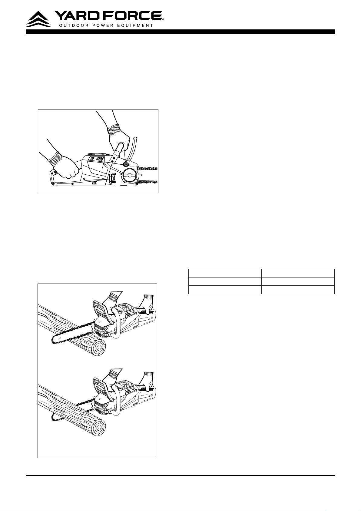
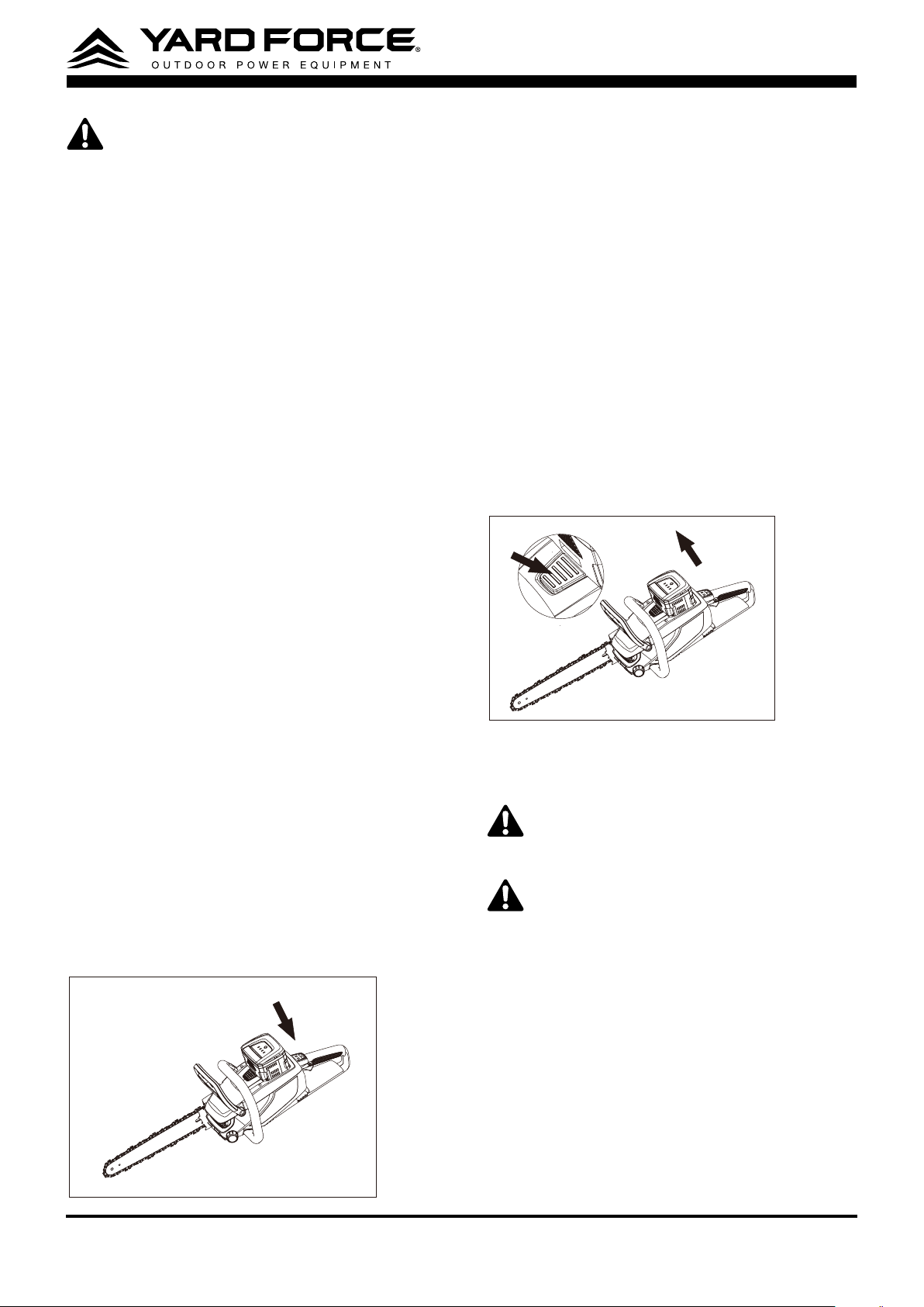
2. Grasp the front and rear handles rmly, using
both hands.
3. Press down the lock-off button rst
①
, then
squeeze the trigger switch to start
②
. (Fig. 22)
1
2
Fig.22
Release the lockoff button and continue to
squeeze the trigger for continued operation.
WARNING:
Do not attempt to start the saw
when the saw chain is in a cut.
To Stop
1. Release the trigger switch.
2. Push the chain kickback brake handle
forward to the brake position to engage the
chain brake (Fig. 21).
Fig.21
WARNING:
Always remove the battery
pack from the chain saw during work
breaks and after nishing work.
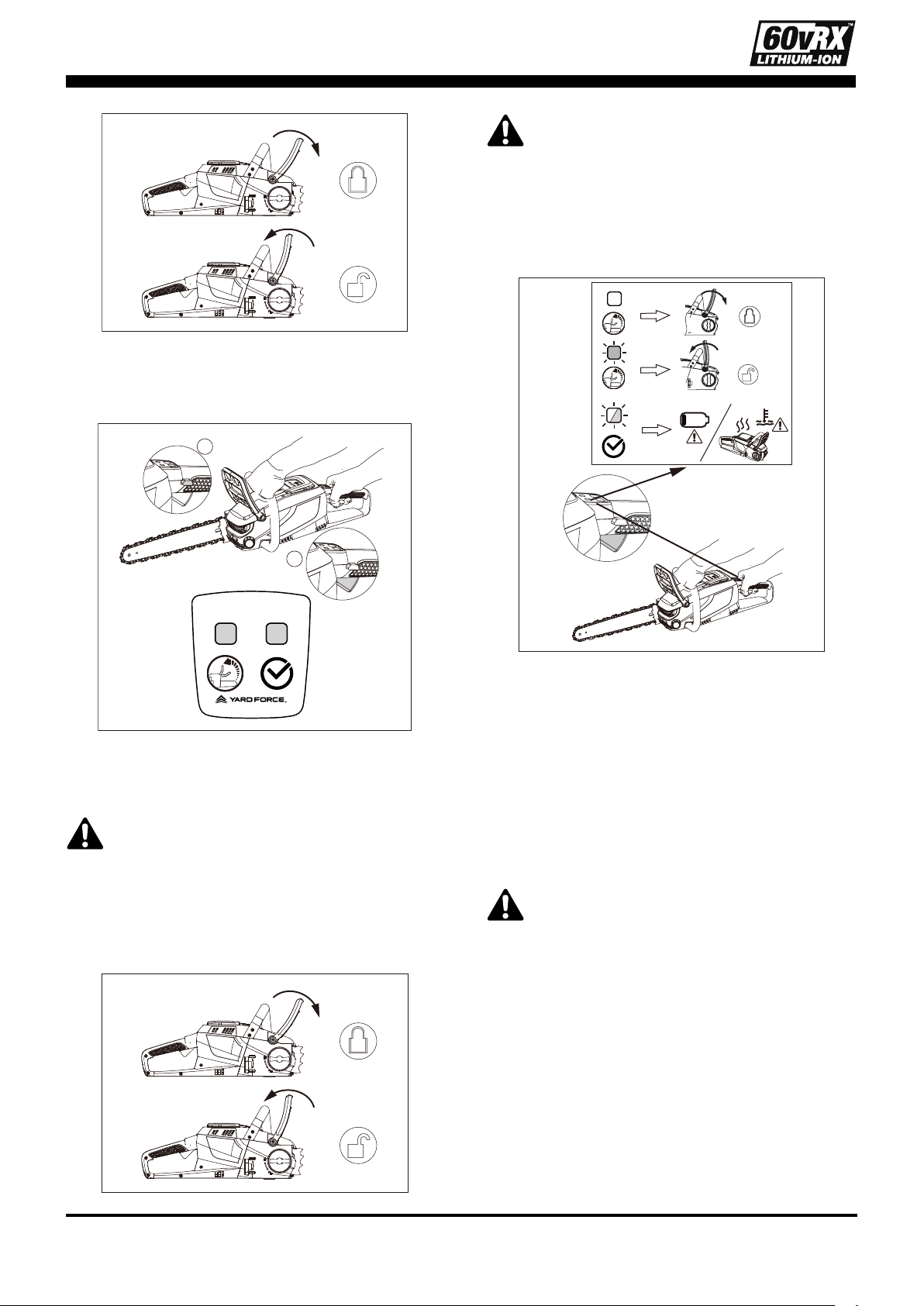
Indicator panel
The indicator panel will be light ON while you
squeeze the trigger switch.
Status meaning as shown in Fig. 23
Fig.23
Proper Grip On Handles
- Wear non-slip gloves for maximum grip and
protection.
- With the saw on a rm, at surface, hold the
saw rmly with both hands.
- Always grasp the front handle with the left
hand and the rear handle with the right.
- The ngers should encircle the handle, with
the thumb wrapped under the front handle.
WARNING:
Never use a left-handed
(cross-handed) grip, or any stance which
would place your body or arm across the
chain line.
Proper Cutting Stance
- Both feet should be on solid ground, with
weight evenly spread between them.
- The left arm should be straight, with the
elbow locked. This helps to withstand the
forces generated by kickback.
- Your body should always be to the left of the
chain line.
16
Instructions concerning the proper
techniques for basic felling, limbing, and
cross-cutting
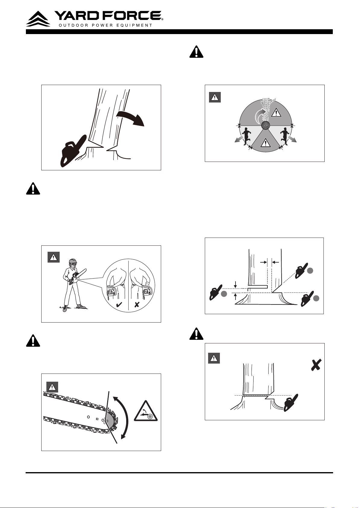
FELLING A TREE (See Fig.24)
Fig.24
WARNING:
Maintain a rm grip, with
thumbs and ngers encircling the chainsaw
handles, with both hands on the saw and
position your body and arm to allow you
to resist kickback forces. Kickback forces
can be controlled by the operator, if proper
precautions are taken. Do not let go of the
chainsaw. (See Fig.25)
Fig.25
WARNING:
Kickback may occur when
the nose or tip of the guide bar touches
an object, or when the wood closes in and
pinches the saw chain in the cut. (See
Fig.26)
Fig.26
WARNING:
An escape path should be
planned and cleared as necessary before
cuts are started. The escape path should
extend back and diagonally to the rear of
the expected line of fall. (See Fig.27)
Fig.27
1. Make the felling back cut at least 5 cm. / 2
in. higher than the horizontal notching cut.
Keep the felling back cut parallel to the
horizontal notching cut. Make the felling
back cut so enough wood is left to act as a
hinge. The hinge wood keeps the tree from
twisting and falling in the wrong direction.
(See Fig.28)
1
3
2
5 cm / 2 in
5 cm / 2 in
Fig.28
WARNING:
Do not cut through the hinge.
(See Fig.29)
Fig.29
2. As the felling gets close to the hinge,
the tree should begin to fall. If there is
any chance that the tree may not fall in
desired direction or it may rock back and
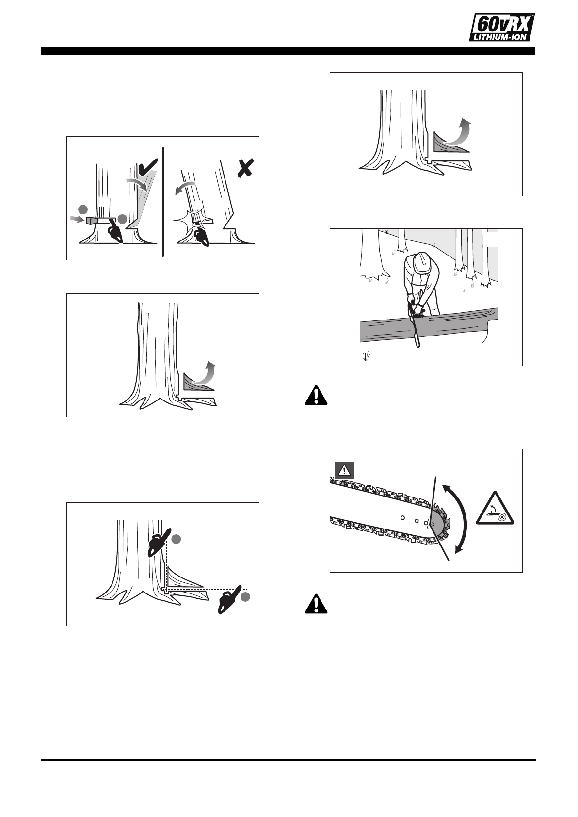
17
bind the saw chain, stop cutting before
the felling back cut is complete and use
wedges of wood, plastic or aluminium to
open the cut and drop the tree along the
desired line of fall. (See Fig.30)
1
2
Fig.30
REMOVING BUTTRESS ROOTS (See Fig.30)
Fig.31
1. A buttress root is a large root extending
from the trunk of the tree above the
ground. Remove large buttress roots
prior to felling. Make the horizontal cut
into the buttress rst, followed by the
vertical cut. (See Fig.32)
1
2
Fig.32
2. Remove the resulting loose section
from the work area. Follow the correct
tree felling procedure after you have
removed the large buttress roots. (See
Fig.33)
Fig.33
BUCKING A LOG (See Fig.34)
Fig.34
WARNING:
Kickback may occur when
the nose or tip of the guide bar touches
an object, or when the wood closes in and
pinches the saw chain in the cut. (See
Fig.35)
Fig.35
WARNING:
The reaction force is always
opposite to the direction the chain is
moving.
Thus, the operator must be ready to control
the tendency for the product to pull away
(forward motion) when cutting on the
bottom edge of the bar. Engage always
rmly the bumper spike to avoid such
movement. The product can be pushed
backwards (towards the operator) when
cutting along the top edge. To avoid this
18
make sure the chain is not jammed when
cutting along the top edge. (See Fig.36)
Fig.36
NOTE:
When the log is supported on both
ends, cut 1/3 the diameter from the top
(overbuck). Then make the nished cut by
underbucking the lower 2/3 to meet the rst
cut.(See Fig.37)
1
2
1/3
2/3
Fig.37
NOTE:
When the log is supported on one
end, cut 1/3 the diameter from the underside
(underbuck). Then make the nished cut by
overbucking to meet the rst cut. (See Fig.38)
2
1
2/3
1/3
Fig.38
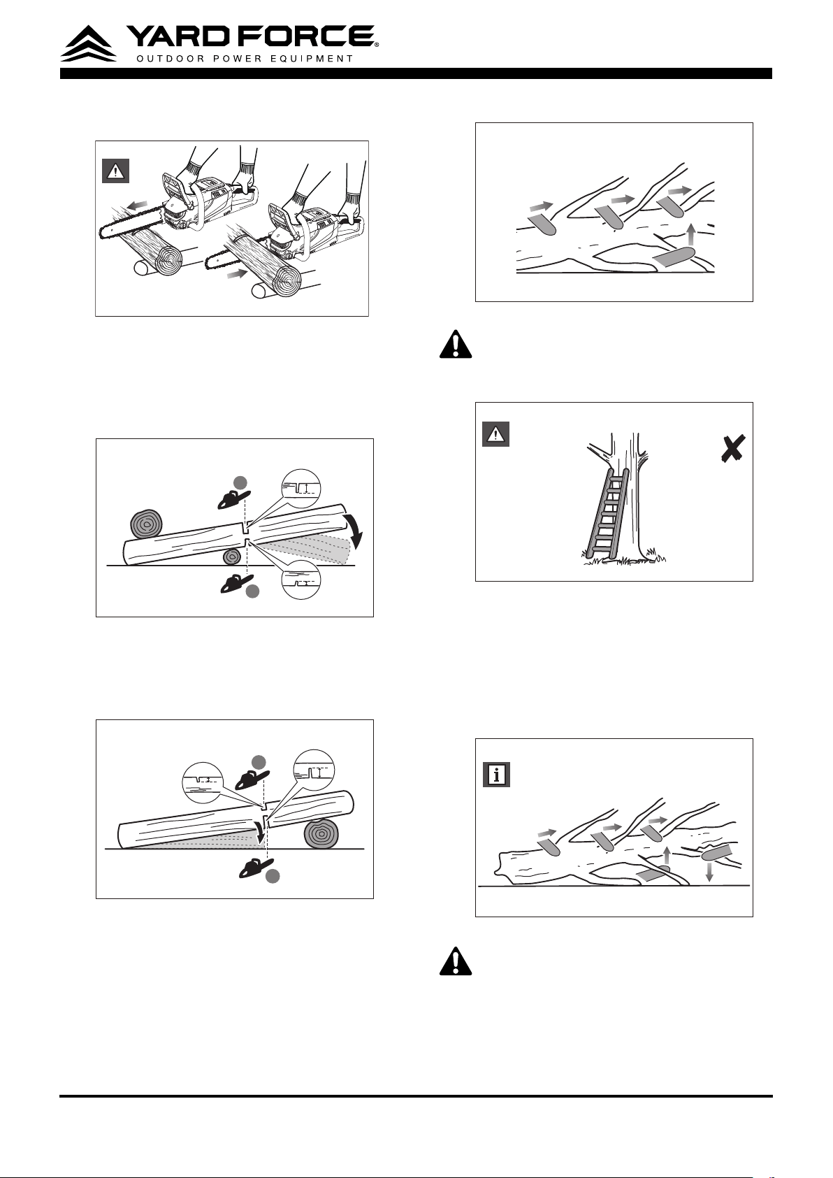
LIMBING A TREE (See Fig.39)
Fig.39
WARNING:
Do not stand on any unstable
surface while using the product. This
could include, but is not limited, to ladders,
scaffolds, and trees.(See Fig.40)
Fig.40
NOTE:
Limbing is removing the branches
from a fallen tree. When limbing leave
larger lower limbs to support the log off the
ground. Remove the small limbs in one cut.
Branches under tension should be cut from
the bottom up to avoid binding the product.(See
Fig.41)
Fig.41
WARNING:
A springpole is any log, branch,
rooted stump, or sapling which is bent
under tension by other wood so that it
springs back if the wood holding it is cut or
removed. On a fallen tree, a rooted stump
has a high potential of springing back to
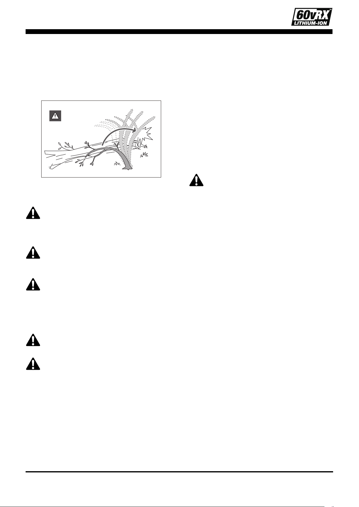
19
the upright position during the bucking cut
to separate the log from the stump. Watch
out for springpoles—they are dangerous.
Do not attempt to cut bent branches or
stumps which are under tension unless you
are professionally trained and competent to
do so.(See Fig.42)
Fig.42
MAINTENANCE AND STORAGE
WARNING
: When servicing, use only
identical replacement parts. Use of any
other parts may create a hazard or cause
product damage.
WARNING:
Always wear protective gloves
when performing any maintenance to the
chain saw.
WARNING:
To avoid serious personal
injury, remove the battery pack from the
chain saw before inspecting, cleaning,
or performing maintenance. A battery
operated tool with the battery pack inserted
is always on and can start accidently.
WARNING:
When cleaning the chain saw,
DO NOT immerse in water or other liquids.
WARNING
: Do not at any time let brake
uids, petrol, petroleum-based products,
penetrating oils, etc., come in contact with
plastic parts. Chemicals can damage,
weaken, or destroy plastic, which may
result in serious personal injury.
CLEANING
- After each use, clean debris from the chain
and guide bar with a soft brush. Wipe
the chain saw surface with a clean cloth
moistened with a mild soap solution.
- Remove the side cover, and then use a soft
brush to remove debris from the guide bar,
saw chain, sprocket and side cover.
- Always clean out wood chips, saw dust,
and dirt from the guide bar groove when
replacing the saw chain.
REPLACING THE BAR AND CHAIN
WARNING:
Never touch or adjust the chain
while the motor is running. The saw chain
is very sharp.
NOTE:
When replacing the guide bar and
chain, always use the specied bar and chain
combination listed in the manual.
Disassemble the Worn Bar and Chain
1. Remove the battery, allow the saw to cool
and tighten the oil tank cap.
2. Position the chain saw on its side with the
side cover facing upwards.
3. Wear gloves. Remove the side cover by
turning the side cover knob anti-clockwise.
Clean the side cover with a dry cloth.
NOTE:
This is a good time to inspect the drive
sprocket for excessive wear or damage.
Assemble The New Bar And Chain
Follow the instructions in the ASSEMBLING/
REPLACING THE BAR AND CHAIN section in
this manual.
Adjust The Chain Tension
Follow the instructions in the ADJUSTING THE
CHAIN TENSION section in this manual.
CHAIN MAINTENANCE
WARNING:
Always wear gloves when handling
the saw chain; these components are sharp and
may contain burrs.
Use only low-kickback chains on this saw. This
fast cutting chain will provide kickback reduction
when properly maintained.

20
A properly sharpened saw chain cuts through
wood effortlessly, even with very little pressure.
Never use a dull or damaged saw chain. A dull
saw chain cutter leads to increased physical
strain, increased vibration load, unsatisfactory
cutting results and increased wear.
For smooth and fast cutting, the chain needs
to be maintained properly. The chain requires
sharpening when the wood chips are small and
powdery, the chain must be forced through the
wood during cutting, or the chain cuts to one
side. During maintenance of your chain, consider
the following:
- Improper ling angle of the side plate can
increase the risk of a severe kickback.
- Raker (depth gauge) clearance. Too low
increases the potential for kickback. Not low
enough decreases cutting ability.
- If cutter teeth have hit hard objects, such as
nails and stones, or have been abraded by
mud or sand on the wood, have the chain
sharpened by a qualied service technician.
NOTE:
Inspect the drive sprocket for wear or
damage when replacing the chain. If signs
of wear or damage are present in the areas
indicated, have the drive sprocket replaced by
qualied service technician.
GUIDE BAR MAINTENANCE
When the guide bar shows signs of wear,
reverse it on the saw to distribute the wear for
maximum bar life. The bar should be cleaned
every day of use and checked for wear and
damage. Feathering or burring of the bar rails is
a normal process of bar wear. Such faults should
be smoothed with a le as soon as they occur.
A bar with any of the following faults should be
replaced.
- Wear inside the bar rails which permits the
chain to lay over sideways.
- Bent guide bar.
- Cracked or broken rails.
- Spread rails.
In addition, the guide bar has a sprocket at its tip.
The sprocket must be lubricated weekly with a
grease syringe to extend the guide bar life. Use a
grease syringe to lubricate weekly with chain oil
by means of the lubricating hole. Turn the guide
bar and check that the lubrication holes and
chain groove are free from impurities.
TRANSPORTING AND STORING
- Do not store or transport the chain saw
when it is running. Always remove the
battery pack before storing or transporting.
- Always place the guide bar sheath on
the guide bar and chain before storing or
transporting the chain saw. Use caution to
avoid the sharp teeth of the chain.
- Clean the chain saw thoroughly before
storing. Store the chain saw indoors, in a dry
place that is locked and/ or inaccessible to
children.
- Keep away from corrosive agents such as
garden chemicals and de-icing salts.

21
TROUBLESHOOTING
Fault/malfunction Cause Remedy
Product does not
Battery pack not properly attached Attach properly
start
Remove and charge the battery
pack
Battery pack damaged Contact our service center
Other electrical defect to the
product
Contact our service center
Product does not reach full
power
Battery pack capacity too low
Remove and charge the battery
pack
Air vents are blocked Clean the air vents
Unsatisfactory result
Accessory is worn Replace with a new one
Accessory not suitable for intended
operation
Use suitable accessory
Product suddenly stops
Product overloaded
Remove the product from the
workpiece and switch it on again
Battery pack discharged
Remove and charge the battery
pack
Battery pack too hot
Remove the battery pack and let it
cool down
Excessive vibration or
noise
Accessory is dull / damaged Replace with a new one
Bolts/nuts are loose Tighten bolts/nuts

22
WARRANTY
Product Warranty
Please keep your original purchase receipt in a safe place as proof of purchase.
Warranty coverage for this product must be veried by the original purchase receipt.
The warranty period begins on the day that the product was purchased from an authorized retailer of
Yard Force products. Warranty coverage only applies to the original purchaser and is not transferrable.
Warranty coverage is only provided on products purchased from authorized Yard Force retailers.
Warranty only applies to products purchased and OPERATED in the USA. Any product purchased or
operated outside of the USA is not covered by any warranty.
(1) Five-Year Warranty on Yard Force Outdoor Power Equipment and
Three- Year Warranty on 60vRX Battery Pack and Adapter
The Yard Force Outdoor Power Equipment has a Five-Year Limited Warranty and 60vRX Battery Pack
and Adapter has a Three-Year Limited Warranty from the date of purchase against manufacturer defects
for residential use only. Commercial use voids the warranty. This warranty does not cover accidental
damage, unreasonable use, normal wear and tear, neglect or non-compliance with the Operating, Safety
and Maintenance Instructions. All service, outside of normal maintenance as described in this manual,
must be done by an authorized service technician. Any unauthorized service or changes to the original
conguration of this product will void the warranty. All parts and accessories used on and with this
product must be manufactured and/or authorized by Merotec Inc.
(2) Ninety-Day Warranty – Accessories
The accessories included with the machine including cutting chain, bar sheath cover, and other similar
parts are warranted against manufacturer defects for residential use only for a period of 90 days from
date of purchase.
Warranty does not cover loss of use or other consequential damages arising from any of the above, nor
does it cover repairs made or attempted by unauthorized persons.
This warranty is void if the product is used for commercial, rental or industrial purposes.
Certain parts, attachments and accessories are subject to normal wear and tear and are excluded from
the warranty.
Service and Warranty Claims Process
Contact the Yard Force Support Center toll-free at
(866) 902-9690 Monday-Friday between 8:30 AM
and 5:00 PM Eastern Time
for service and warranty support.
Yard Force Service Support agents can help you troubleshoot problems over the phone to get you back
up and running as quickly as possible. In the situation where service or warranty inspection is needed,
please follow these steps:
1. Call Yard Force at
(866) 902-9690 Monday-Friday between 8:30 AM and 5:00 PM Eastern Time
.
2. Send in proof-of-purchase and serial number (if applicable) to conrm warranty Coverage as directed
by Yard Force.
3. If service or a warranty evaluation is requested, Yard Force will provide an RGA number that should be
used in all communications with Yard Force and is required to be indicated on the product itself and on
the outside of the box.
4. All shipments to Yard Force must have an RGA number. Any shipment received that does not have an
RGA number clearly marked on the outside of the box will be refused.
5. All shipments must be sent pre-paid, Yard Force does not pay for any shipping costs for service or
warranty evaluation. Yard Force is not responsible for any packages that are lost by carrier. We
recommend that shipments are made by a carrier that provides tracking and delivery conrmation.
For more information or to ask questions, please call toll-free
(866) 902-9690 Monday-Friday between
8:30 AM and 5:00 PM Eastern Time
.
SAVE THESE INSTRUCTIONS
Need Help?
Please do not return the product to the place of purchase yet.
We’re here to help and take care of all your needs.
Contact our Customer Care Center in
Atlanta, GA for help with:
Product assembly or use
Missing or damaged parts
Troubleshooting
You can also visit our website to download
owner's manuals and get additional product information.
Visit www.YardForceUSA.com, or call our
toll free hotline: 1-866-902-9690 M-F 8:30am – 5:00pm ET
1-866-902-9690 [email protected]
Merotec Inc.
3655 Kennesaw North Industrial Parkway, Kennesaw, GA 30144
© Copyright 2020 Merotec Inc.
Made in China at a SUMEC manufacturing facility.
MADE IN CHINA