Loading ...
Loading ...
Loading ...
L8148A,E,J AQUASTAT® RELAYS
95-6940—12
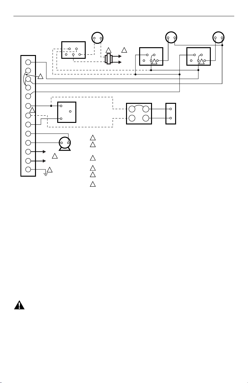
Fig. 7. Wiring L8148J for multizone control.
OPERATION AND SETTING
High Limit
The high limit switch shuts off the burner when the boiler
temperature exceeds high-limit setting. Because heating
systems differ, the correct temperature setting for one
system might not be correct for another. Follow the boiler
manufacturer recommendation for proper setting. To set,
remove cover, and turn dial until the desired setting is
directly below the pointer.
The dial stop is factory-set at the high end of the limit
scale. To adjust, use a small screwdriver to hold the stop
away from the dial face, and turn the dial until the desired
setting is below the pointer. See Fig. 8. Release pressure
on screwdriver, and make sure the stop rests flat against
the dial face.
WARNING
Explosion Hazard.
Can cause severe injury, death or property
damage.
This product is intended for use only in systems
with a pressure relief valve.
Switching Relay
The switching relay is controlled by the room thermostat.
On a call for heat, the relay coil is energized, completing
the line voltage circulator circuit and also the burner
circuit, if the boiler water temperature is below the high
limit setting.
Auto-Manual Switch
The AUTO-MANUAL switch (only L8148J millivolt
models) makes it possible to operate the burner (in a
system with a millivoltage gas valve) during an electrical
power failure. With switch at MANUAL, the burner
operates continuously until either the high limit setting is
reached or the switch is reset to AUTO. The circulator,
requiring line voltage, is inoperative. When power is
restored, the switch must be set to AUTO to resume
automatic burner operation.
L1
HOT
L2
1
END SWITCH
END SWITCH END SWITCH
TV
TP
W
Z
T
B1
B2
B3
C1
C2
L1
L2
G
4 4
TH1 PP
TH2
PP
TR
TH
THTR
LOW VOLTAGE GAS
VALVE (eg, VR8300)
MILLIVOLTAGE
GAS VALVE
POWERPILE
®
L1
HOT
L2
1
CIRCULATOR
POWER SUPPLY. PROVIDE DISCONNECT MEANS AND OVERLOAD PROTECTION AS REQUIRED.
L8184J POWERS TWO V8043E OR F ZONE VALVES, OR ONLY ONE V8043 WHEN AMBIENT
TEMPERATURE EXCEEDS 77
o
F (25
o
C). USE AN ADDITIONAL TRANSFORMER(S) TO
POWER ADDITIONAL VALVES.
LINK MUST BE USED WHEN USING 24 VOLT GAS VALVE HOOKUP (B1–B3). REMOVE LINK
WHEN MILLIVOLTAGE GAS VALVE IS USED (B1–B2).
ADD JUMPER.
CONTROL CASE MUST BE CONNECTED TO EARTH GROUND. USE GROUNDING SCREW
PROVIDED.
B1 IS 1/4 IN. TAB TERMINAL.
1
2
3
4
5
6
6
5
2
3
24 VOLT
THERMOSTAT
24 VOLT
THERMOSTAT
24 VOLT
THERMOSTAT
ZONE 3
ZONE 2 ZONE 1
L8148J
V8043F
V8043F
V8043F
M2887A
Loading ...
Loading ...