Loading ...
L8148A,E,J AQUASTAT® RELAYS
95-6940—12
WARNING
Electrical Shock Hazard.
Can cause severe injury, death or property
damage.
1. Disconnect power supply before beginning
installation to prevent electrical shock or
equipment damage.
2. Never apply a jumper across (or short)
terminals B1, B2, or B3. This burns out the
transformer.
Mounting
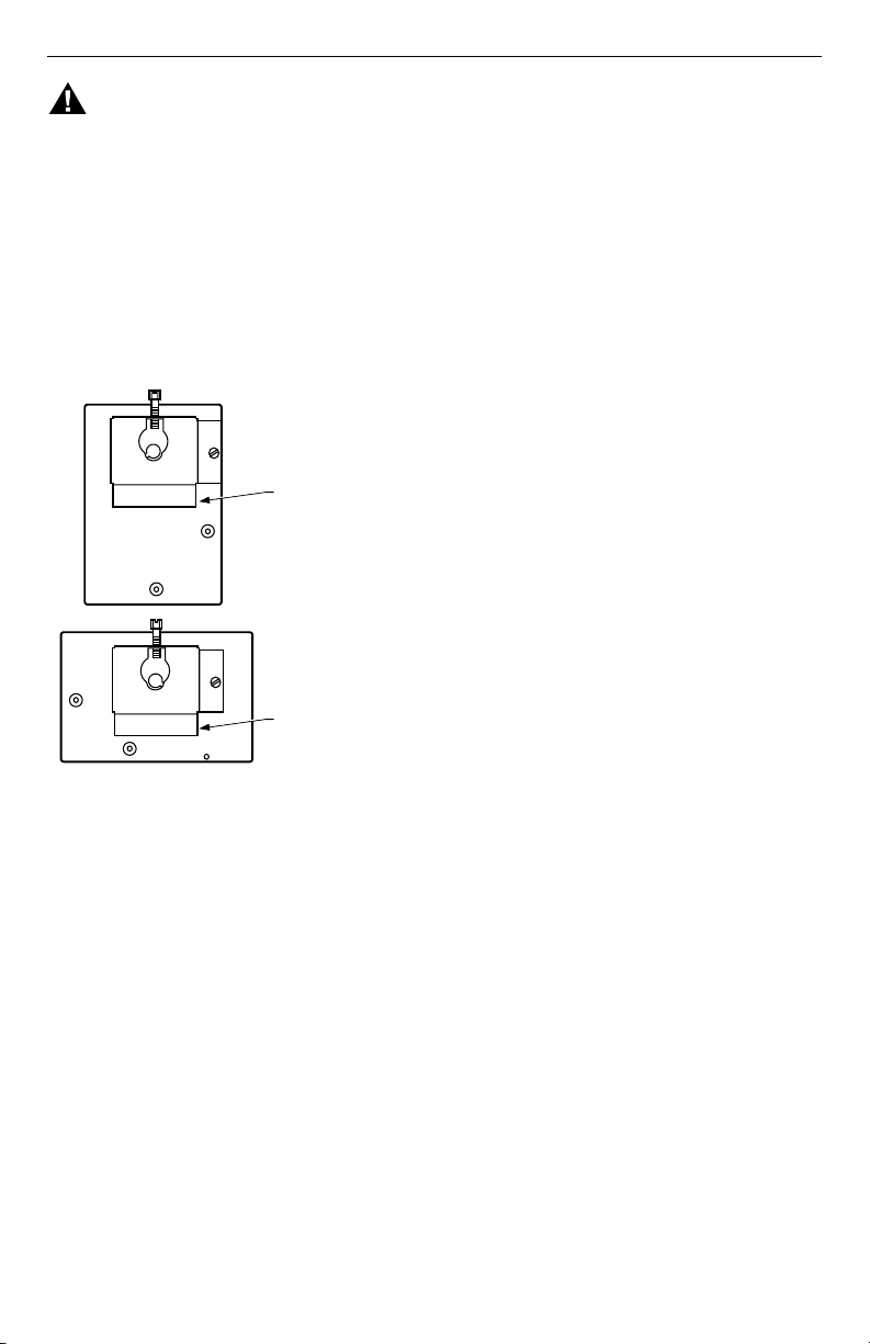
The L8148A,J has a case that can be converted to either
horizontal or vertical mounting (Fig. 1).
Fig. 1. Case is designed for vertical
or horizontal mounting.
New Installation
Order well assemblies and 124904 Well Adapter for the
Aquastat Relay separately; refer to form 68-0040, Wells
and Fittings for Temperature Controllers. Boilers usually
have tappings that allow the well to be mounted
horizontally so boiler water of average temperature can
circulate freely.
1. Turn off all power and drain the boiler.
2. If no tapping is provided, prepare properly sized
and threaded tapping near the top of the boiler.
3. Coat the well threads sparingly with pipe dope;
install the well in the boiler tapping and tighten
securely.
NOTE: Do not attempt to tighten by using the case as a
handle.
4. Refill boiler and check for water leakage.
5. Insert the bulb element into the well until it bottoms.
If necessary, slightly bend the tube inside the case
to hold the bulb against the bottom of the well.
6. Center the loop of excess tubing in front of the
immersion well so it cannot touch any electrical
parts.
NOTE: Some models have an adjustable tubing length
to 3 in. (76 mm). For these models, pull out
extra tubing from inside the case, if needed.
7. Fit the case into the well so the clamp on the case
slides over the flange on the well.
IMPORTANT
Best thermal response is obtained with a well
that snugly fits the sensing bulb. Insert the bulb
until it rests against the bottom of the well. Use
a well of correct length and bend the tubing, if
necessary, to hold the bulb against the bottom
of the well, but do not make a sharp bend in the
tubing.
If the well is not a snug fit on the bulb, use the
heat-conductive compound (furnished with
TRADELINE® models) as follows: Fold the
plastic bag of compound lengthwise and twist it
gently. Then snip off end of bag and work the
open end of bag all the way into the well. Slowly
pull the bag out while squeezing it firmly to
distribute compound evenly in the well. Bend
the tubing, if necessary, to hold the bulb against
the bottom of the well and to hold outer end of
the bulb in firm contact with the side of the well.
See Fig. 2. Wipe excess compound from the
outer end of the well.
Replacement Installation
Turn off all power and remove the old control. Refer to
the cover insert of the old control to identify and tag each
external lead as it is disconnected. If old well is
unsuitable for new installation, remove it and proceed
with instructions for new installation. If old well is suitable,
use it and a 124904 immersion well adapter (ordered
separately from form 68-0040, Wells and Fittings for
Temperature Controllers) for the installation. (If the well
clamp fits directly over the flange of the existing well
spud, adapter use is not necessary.) The adapter has a
flange at the wide end that fits into the well clamp and is
slotted lengthwise to accommodate both the capillary
tube and the short length of tube extending from the bulb.
1. Loosen but do not remove the well clamp screw on
the side of the control case.
2. Pull out the capillary until the bulb bottoms in the
well. Place adapter (if used) around the capillary
tube so it fits into the slot. See Fig. 2. Center the
loop of excess capillary tubing in front of the
immersion well so it cannot touch any electrical
parts.
NOTE: Some models have a tubing length adjustable to
3 in. (76 mm). For these models, extra tubing
inside the case can be pulled out, if needed.
3. Make sure the wide end of the adapter fits into the
hole in the case. Position immersion well clamp
snugly over the flange on the adapter and tighten
the clamp screw.
4. Insert sensing bulb into well as shown in Fig. 2.
(Distribute the heat-conductive compound in the
tube prior to bulb insertion.)
5. Securely tighten setscrew (if present on old well)
against adapter.
BRACKET POSITION FOR
VERTICAL MOUNTING
BRACKET POSITION FOR
HORIZONTAL MOUNTING
M8890
Loading ...
Loading ...
Loading ...