® U.S. Registered Trademark
Copyright © 2002 Honeywell • •All Rights Reserved
INSTALLATION INSTRUCTIONS
95- 6940- 12
L8148A,E,J
Aquastat® Relays
APPLICATION
The L8148A,E,J Aquastat® Relays are immersion-type
controllers for use with forced hydronic heating systems.
The combination high limit and intermediate switching
relay works with a low voltage (24V) thermostat to control
burner and circulator circuits. A call for heat by the
thermostat starts both the burner and the circulator.
When boiler-water temperature exceeds the high-limit
settings, the burner circuit is broken; the circulator
continues to operate during the thermostat call for heat.
The L8148A controls line-voltage burner circuits; the
L8148E,J control low-voltage burner circuits; the L8148J
controls millivoltage burner circuits. All models control
line-voltage circulator circuits.
L8148A,E,J have provisions for adding low-limit
controllers; L8148E,J can power valves in multizone
systems.
L8148E is available with a plug and 50 VA transformer for
use with Honeywell Smart Valve SV9500/SV9600.
SPECIFICATIONS
Electrical Ratings:
Table 1. Circulator Control Circuit (A):
Table 2. Burner Control Circuit:
Scale Range: 140°F to 240°F (60°C to 116°C) or 180°F
to 240°F (82°C to 116°C).
Differential: Nonadjustable.
High Limit Dial Stop: Adjustable.
Maximum Pressure on Immersion Well: 255 psi (1758
kPa).
Maximum Ambient Temperature: 150°F (66°C) with
1.2A, 24V load; 77°F (25°C) with 1.4A, 24V load.
Maximum Bulb Temperature: 40°F over setpoint, up to
265°F (4°C over setpoint, up to 129°C).
Thermostat Heat Anticipator Setting: 0.2A.
Material Safety Data Sheets (MSDS): For information
on heat-conductive compound, see form number
69-0955.
INSTALLATION
When Installing This Product…
1. Read these instructions carefully. Failure to follow
them could damage the product or cause a
hazardous condition.
2. Check the ratings given in the instructions and on
the product to make sure the product is suitable for
your application.
3. Installer must be a trained, experienced service
technician.
4. After installation is complete, check out product
operation as provided in these instructions.
WARNING
Explosion Hazard.
Can cause severe injury, death or property
damage.
This product is intended for use only in systems
with a pressure relief valve.
Type 120 Vac 240 Vac
Full Load 7.4 3.7
Locked Rotor 44.4 22.7
Model No. Voltage Electrical Rating
L8148A Line Same as circulator control
circuit.
L8148E,J Low 0.8A maximum at 24 Vac.
L8148A,E,J AQUASTAT® RELAYS
95-6940—12
WARNING
Electrical Shock Hazard.
Can cause severe injury, death or property
damage.
1. Disconnect power supply before beginning
installation to prevent electrical shock or
equipment damage.
2. Never apply a jumper across (or short)
terminals B1, B2, or B3. This burns out the
transformer.
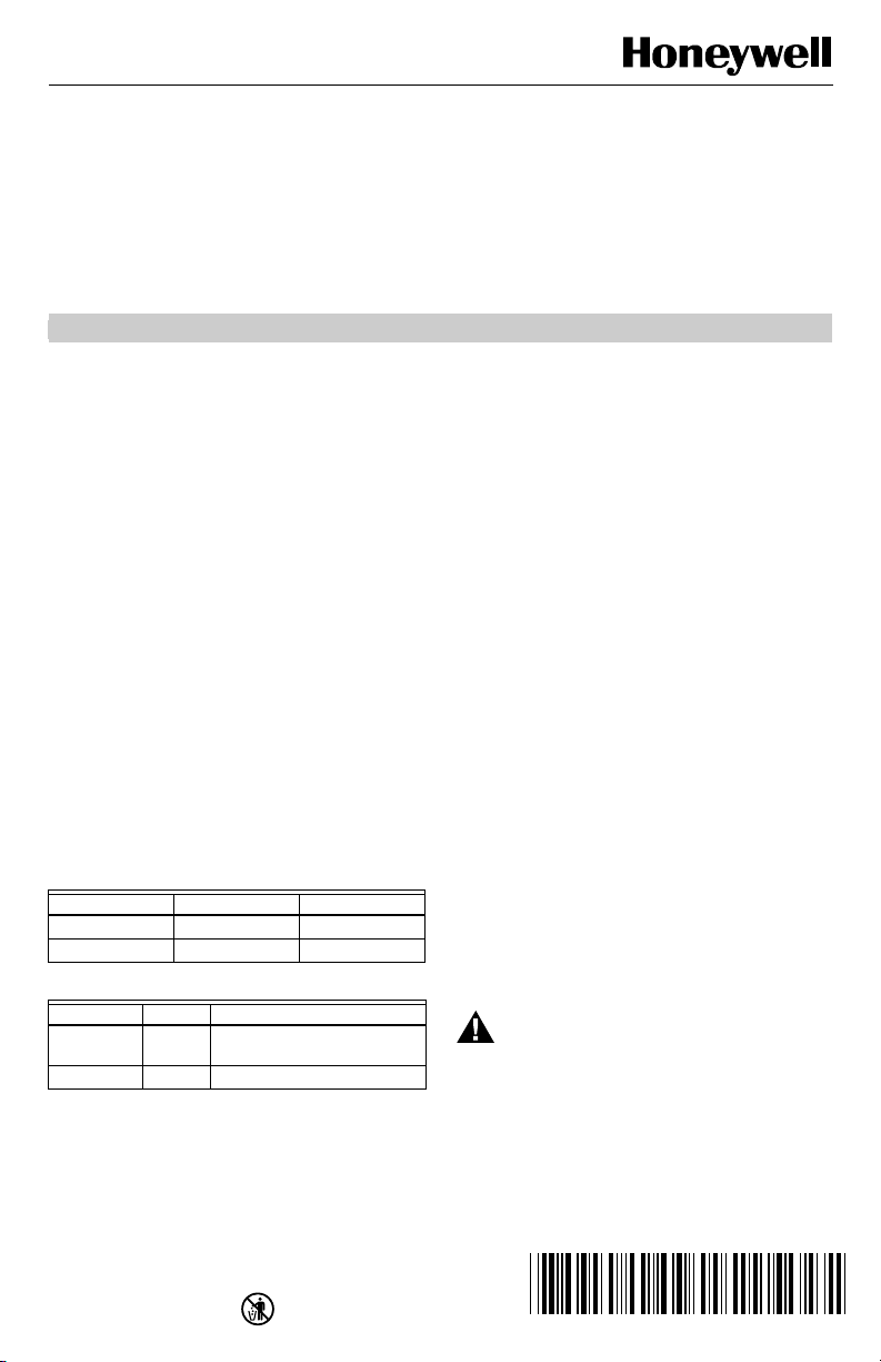
Mounting
The L8148A,J has a case that can be converted to either
horizontal or vertical mounting (Fig. 1).
Fig. 1. Case is designed for vertical
or horizontal mounting.
New Installation
Order well assemblies and 124904 Well Adapter for the
Aquastat Relay separately; refer to form 68-0040, Wells
and Fittings for Temperature Controllers. Boilers usually
have tappings that allow the well to be mounted
horizontally so boiler water of average temperature can
circulate freely.
1. Turn off all power and drain the boiler.
2. If no tapping is provided, prepare properly sized
and threaded tapping near the top of the boiler.
3. Coat the well threads sparingly with pipe dope;
install the well in the boiler tapping and tighten
securely.
NOTE: Do not attempt to tighten by using the case as a
handle.
4. Refill boiler and check for water leakage.
5. Insert the bulb element into the well until it bottoms.
If necessary, slightly bend the tube inside the case
to hold the bulb against the bottom of the well.
6. Center the loop of excess tubing in front of the
immersion well so it cannot touch any electrical
parts.
NOTE: Some models have an adjustable tubing length
to 3 in. (76 mm). For these models, pull out
extra tubing from inside the case, if needed.
7. Fit the case into the well so the clamp on the case
slides over the flange on the well.
IMPORTANT
Best thermal response is obtained with a well
that snugly fits the sensing bulb. Insert the bulb
until it rests against the bottom of the well. Use
a well of correct length and bend the tubing, if
necessary, to hold the bulb against the bottom
of the well, but do not make a sharp bend in the
tubing.
If the well is not a snug fit on the bulb, use the
heat-conductive compound (furnished with
TRADELINE® models) as follows: Fold the
plastic bag of compound lengthwise and twist it
gently. Then snip off end of bag and work the
open end of bag all the way into the well. Slowly
pull the bag out while squeezing it firmly to
distribute compound evenly in the well. Bend
the tubing, if necessary, to hold the bulb against
the bottom of the well and to hold outer end of
the bulb in firm contact with the side of the well.
See Fig. 2. Wipe excess compound from the
outer end of the well.
Replacement Installation
Turn off all power and remove the old control. Refer to
the cover insert of the old control to identify and tag each
external lead as it is disconnected. If old well is
unsuitable for new installation, remove it and proceed
with instructions for new installation. If old well is suitable,
use it and a 124904 immersion well adapter (ordered
separately from form 68-0040, Wells and Fittings for
Temperature Controllers) for the installation. (If the well
clamp fits directly over the flange of the existing well
spud, adapter use is not necessary.) The adapter has a
flange at the wide end that fits into the well clamp and is
slotted lengthwise to accommodate both the capillary
tube and the short length of tube extending from the bulb.
1. Loosen but do not remove the well clamp screw on
the side of the control case.
2. Pull out the capillary until the bulb bottoms in the
well. Place adapter (if used) around the capillary
tube so it fits into the slot. See Fig. 2. Center the
loop of excess capillary tubing in front of the
immersion well so it cannot touch any electrical
parts.
NOTE: Some models have a tubing length adjustable to
3 in. (76 mm). For these models, extra tubing
inside the case can be pulled out, if needed.
3. Make sure the wide end of the adapter fits into the
hole in the case. Position immersion well clamp
snugly over the flange on the adapter and tighten
the clamp screw.
4. Insert sensing bulb into well as shown in Fig. 2.
(Distribute the heat-conductive compound in the
tube prior to bulb insertion.)
5. Securely tighten setscrew (if present on old well)
against adapter.
BRACKET POSITION FOR
VERTICAL MOUNTING
BRACKET POSITION FOR
HORIZONTAL MOUNTING
M8890
L8148A,E,J AQUASTAT® RELAYS
3 95-6940—12
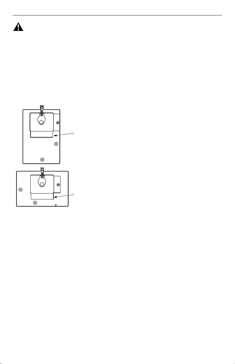
Fig. 2. Proper position of sensing bulb in immersion well, and use of well adapter in existing well.
WIRING
IMPORTANT
The terminals of these Aquastat® Relays are
approved for use with copper wire only.
WARNING
Electrical Shock Hazard.
Can cause severe injury, death or property
damage.
Disconnect power supply before making wiring
connections to prevent electrical shock or
equipment damage.
All wiring must comply with local electrical codes and
ordinances. Do not exceed the specifications in the
Application section when applying this control.
L8148J can power up to two V8043 Zone Valves.
Additional valves, in groups of two or less, require an
additional transformer. Follow the appropriate wiring
diagrams when using zone valves or a low limit
controller. See Fig. 3 through 7.
If the B1 terminal on the device being replaced is a 1/4 in.
tab terminal, use the existing wiring harness terminals to
install the replacement device. If the B1 terminal on the
device being replaced is a screw terminal, insert the
provided tab terminal to screw terminal adapter onto the
1/4 in. tab terminal of the replacement device. After the
adapter is installed, reuse the existing wraparound wire
end to make an electrical connection to the B1 terminal.
CAUTION
Equipment Damage Hazard.
Can cause incorrect operation.
1.If L8148E,J are used to power zone valves,
low voltage (24 Vac) load must not exceed
1.4A; a 1.2A load is the maximum permissible
when ambient temperature exceeds 77°F
(25°C). Use additional transformer(s) when
load exceeds these ratings.
2.When L8148E is used to power SV9500/
SV9600, use separate transformer to power
zone valves.
CONTROLLER
CASE
IMMERSION
WELL CLAMP
ADAPTER
IMMERSION
WELL SPUD
BOILER
OLD IMMERSION
WELL ASSEMBLY
BACK OF
CONTROLLER
CASE
IMMERSION
WELL CLAMP
SCREW
ADAPTER
SENSING
BULB
HEAT-CONDUCTIVE COMPOUND
SETSCREW
CAPILLARY
TUBE
(C)
IMMERSION
WELL CLAMP
IMMERSION
WELL CLAMP SCREW
SHORT TUBE
FITS IN CENTRAL
RECESS OF ADAPTER
BEND THE CAPILLARY TUBE TO HOLD THE SENSING BULB IN GOOD
THERMAL CONTACT WITH THE IMMERSION WELL AT POINTS (A) AND (B).
ASSURE THAT CAPILLARY TUBE FITS FREELY IN THE ADAPTER SO THE
TENSION OF THE CAPILLARY TUBE AT POINT (C) HOLDS THE SENSING
BULB IN GOOD THERMAL CONTACT WITH THE IMMERSION WELL AT POINT (D).
M8830
1
1
2
2
(D)
(B)
(A)
L8148A,E,J AQUASTAT® RELAYS
95-6940—12
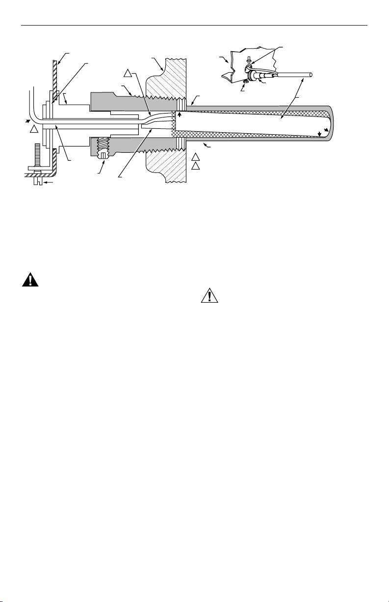
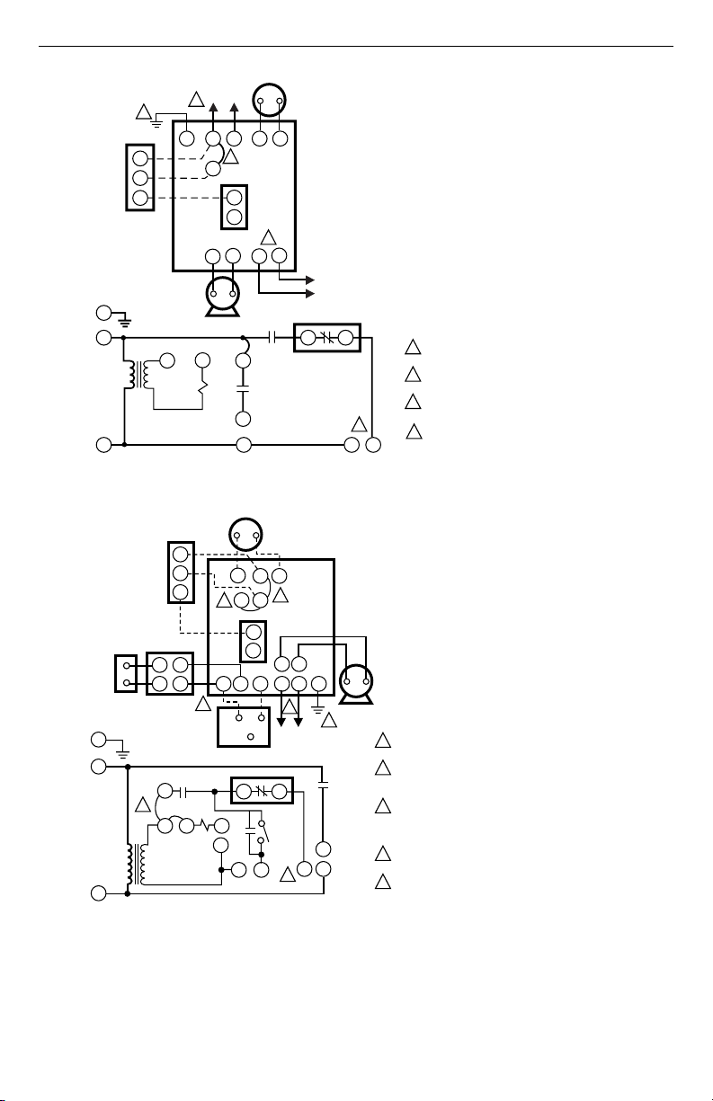
Fig. 3. External connections and internal schematic for L8148A.
Fig. 4. Internal schematic and external connections for L8148J with either low voltage or
millivoltage gas valves. Low limit added in hookup with 24V gas valve.
C1
C2
B1
B2
R
W
B
G
L1
L2
T
T
3
B
R
L1
L2
G
T
T3
C1
C2
B2 B1
JUMPER
1K
1K2
1K1
B
R
L6006
LOW LIMIT
CONTROLLER
L1
HOT
L2
24V
THERMOSTAT
L8148A
HIGH
LIMIT
TO LINE
VOLTAGE
OIL BURNER
RELAY OR
GAS VALVE
CIRCULATOR
POWER SUPPLY. PROVIDE DISCONNECT MEANS
AND OVERLOADPROTECTION AS REQUIRED.
REMOVE JUMPER WHEN ADDING L6006 LOW
LIMIT CONTROLLER.
CONTROL CASE MUST BE CONNECTED TO EARTH
GROUND. USE GROUNDING SCREW PROVIDED.
B1 IS 1/4 IN. TAB TERMINAL.
1
2
3
4
4
1
2
3
M2842A
L8148A
4
L1
(HOT)
L2
1
1
4
5
5
1
2
3
4
5
2
3
POWER SUPPLY. PROVIDE DISCONNECT MEANS
AND OVERLOAD PROTECTION AS REQUIRED.
REMOVE Z-W JUMPER IF SERIES 60 LOW LIMIT IS USED.
WIRE LOW LIMIT CONTROLLER OR ZONE VALVES AS
SHOWN. USE WITH 24V (B1-B3) CIRCUIT ONLY.
FOR 24V BURNER, WIRE B1-B3 AND USE JUMPER Z-W
AND TP-Z. FOR POWERPILE® (MILLIVOLTAGE) GAS
VALVES, REMOVE JUMPER TP-Z AND WIRE BURNER
B1-B2. JUMPER Z-W REMAINS IN POSITION.
CONTROL CASE MUST BE CONNECTED TO EARTH
GROUND. USE GROUNDING SCREW PROVIDED.
B1 IS 1/4 IN. TAB TERMINAL.
L6006
LOW LIMIT
CONTROLLER
POWERPILE®
MILLIVOLTAGE
GAS VALVE
PP
PP
TH2
TH1
W
R
R
R
B
B
B
24V
THERMOSTAT
L8148J
CIRCULATOR
G
G
L1
L1
L2B3B2B1
HIGH
LIMIT
TP
TV
T
W
Z
C1
C2
TR
TH
THTR
LOW VOLTAGE
GAS VALVE
(eg, VR8300)
1K3
TP
Z
WT
TV
1K2
AUTO
MANUAL
SWITCH
1K1
C1
C2
B3
B2
B1
L2
L8148J
M1793B
L8148A,E,J AQUASTAT® RELAYS
5 95-6940—12
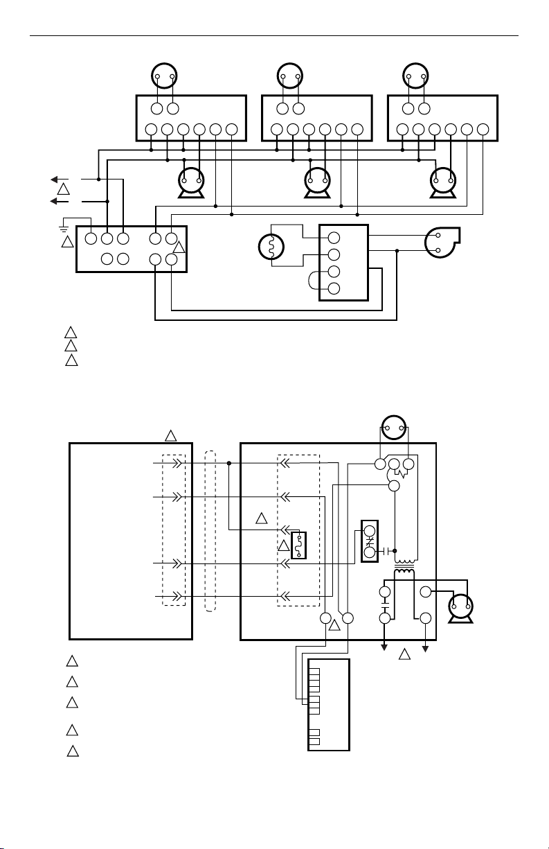
Fig. 5. Wiring L8148A in oil-fired, forced hot water, tankless, zoned, pump system.
Fig. 6. Wiring L8148E1265 with internal plug directly to vent damper in hydronic intermittent pilot system.
TT
1
23
4
5
6
TT
1
23
4
5
6
TT
1
23
4
5
6
GL2L1 T T
C1 C2
B2 B1
F
F
T
T
L1
(HOT)
L2
PUMP PUMP PUMP
T87F T87F T87F
R845
RELAY
R845 R845
C554
R8184G
BURNER
AND
IGNITION
ORANGE
WHITE
BLACK
POWER SUPPLY. PROVIDE DISCONNECT MEANS AND OVERLOAD PROTECTION AS REQUIRED.
CONTROL CASE MUST BE CONNECTED TO EARTH GROUND. USE GROUNDING SCREW PROVIDED.
B1 IS 1/4 IN. TAB TERMINAL.
1
2
L8148A
2
1
M2843A
3
3
24V GND
24V
S8600
L1
(HOT)
L2
1
1
2
3
4
5
L8148E1265
4
2
3
3
FUSE
5
1
2
5
6-PRONG FEMALE MOLEX
RECEPTABLE IN L8148E
AND 5-PRONG MALE
MOLEX PLUG ON CABLE
1K1
B1
B2
L1
C1 C2
L2
CIRCULATOR
POLARIZED 4-PRONG
MALE MOLEX PLUG AND
4-PRONG FEMALE
MATING PLUG ON CABLE
1
2
3
4
24 VAC
THERMOSTAT
D892/M892
4 197516A
CABLE
POWER SUPPLY. PROVIDE DISCONNECT MEANS AND OVERLOAD
PROTECTION AS REQUIRED.
REMOVE PLUG-IN THAT JUMPERS PINS 2 AND 3 WHEN USING VENT
DAMPER.
AFTER VENT DAMPER IS PLUGGED INTO L8148E1265, FUSE BLOWS
WHEN THERMOSTAT FIRST CLOSES. AFTER FUSE BLOWS, L8148E1265
OPERATES ONLY WHEN VENT DAMPER IS CONNECTED.
SEE VENT DAMPER PRODUCT SPECIFICATIONS FOR INTERNAL
SCHEMATICS.
B1 IS 1/4 IN. TAB TERMINAL.
M2763C
1K2
HIGH LIMIT
CONTROLLER
R
B
TV
W
T
1K
Z
L8148A,E,J AQUASTAT® RELAYS
95-6940—12
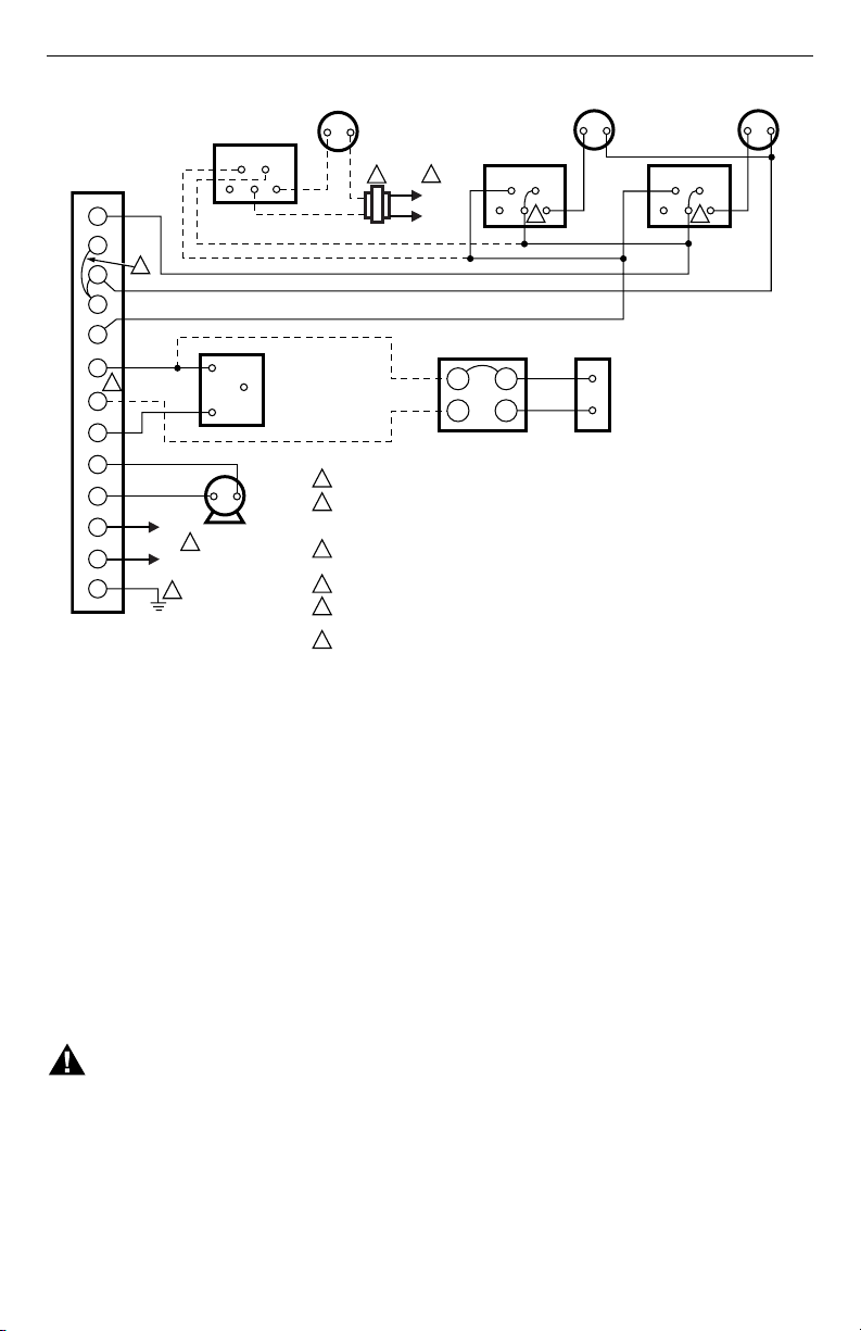
Fig. 7. Wiring L8148J for multizone control.
OPERATION AND SETTING
High Limit
The high limit switch shuts off the burner when the boiler
temperature exceeds high-limit setting. Because heating
systems differ, the correct temperature setting for one
system might not be correct for another. Follow the boiler
manufacturer recommendation for proper setting. To set,
remove cover, and turn dial until the desired setting is
directly below the pointer.
The dial stop is factory-set at the high end of the limit
scale. To adjust, use a small screwdriver to hold the stop
away from the dial face, and turn the dial until the desired
setting is below the pointer. See Fig. 8. Release pressure
on screwdriver, and make sure the stop rests flat against
the dial face.
WARNING
Explosion Hazard.
Can cause severe injury, death or property
damage.
This product is intended for use only in systems
with a pressure relief valve.
Switching Relay
The switching relay is controlled by the room thermostat.
On a call for heat, the relay coil is energized, completing
the line voltage circulator circuit and also the burner
circuit, if the boiler water temperature is below the high
limit setting.
Auto-Manual Switch
The AUTO-MANUAL switch (only L8148J millivolt
models) makes it possible to operate the burner (in a
system with a millivoltage gas valve) during an electrical
power failure. With switch at MANUAL, the burner
operates continuously until either the high limit setting is
reached or the switch is reset to AUTO. The circulator,
requiring line voltage, is inoperative. When power is
restored, the switch must be set to AUTO to resume
automatic burner operation.
L1
HOT
L2
1
END SWITCH
END SWITCH END SWITCH
TV
TP
W
Z
T
B1
B2
B3
C1
C2
L1
L2
G
4 4
TH1 PP
TH2
PP
TR
TH
THTR
LOW VOLTAGE GAS
VALVE (eg, VR8300)
MILLIVOLTAGE
GAS VALVE
POWERPILE
®
L1
HOT
L2
1
CIRCULATOR
POWER SUPPLY. PROVIDE DISCONNECT MEANS AND OVERLOAD PROTECTION AS REQUIRED.
L8184J POWERS TWO V8043E OR F ZONE VALVES, OR ONLY ONE V8043 WHEN AMBIENT
TEMPERATURE EXCEEDS 77
o
F (25
o
C). USE AN ADDITIONAL TRANSFORMER(S) TO
POWER ADDITIONAL VALVES.
LINK MUST BE USED WHEN USING 24 VOLT GAS VALVE HOOKUP (B1–B3). REMOVE LINK
WHEN MILLIVOLTAGE GAS VALVE IS USED (B1–B2).
ADD JUMPER.
CONTROL CASE MUST BE CONNECTED TO EARTH GROUND. USE GROUNDING SCREW
PROVIDED.
B1 IS 1/4 IN. TAB TERMINAL.
1
2
3
4
5
6
6
5
2
3
24 VOLT
THERMOSTAT
24 VOLT
THERMOSTAT
24 VOLT
THERMOSTAT
ZONE 3
ZONE 2 ZONE 1
L8148J
V8043F
V8043F
V8043F
M2887A
L8148A,E,J AQUASTAT® RELAYS
7 95-6940—12
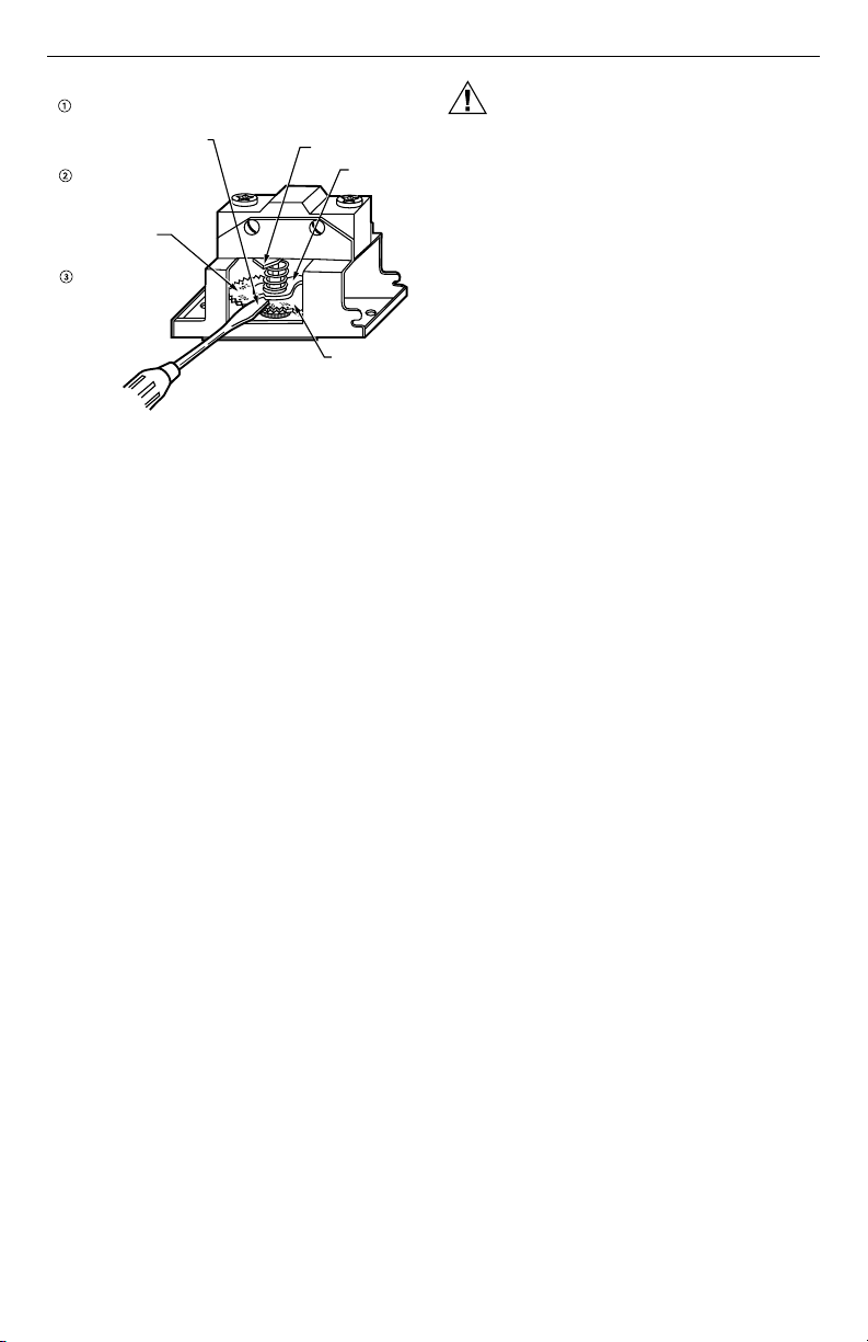
Fig. 8. Setting high limit stop.
CAUTION
Equipment Damage Hazard.
Improper procedure will damage equipment.
Never apply a jumper across (or short) terminals
B1, B2, or B3. This burns out the transformer.
CHECKOUT
Put the system into operation and observe through at
least one complete cycle to be sure control operates as
described above.
INSERT CORNER OF SMALL
SCREWDRIVER IN THIS
NOTCH AND PRY STOP
UPWARD FROM DIAL FACE
WHILE HOLDING STOP AWAY
FROM DIAL FACE WITH
SCREWDRIVER, TURN
DIAL UNTIL DESIRED HIGH
LIMIT SETTING IS ALIGNED
WITH POINTER
RELEASE SCREWDRIVER;
MAKE SURE HIGH-LIMIT
STOP RESTS FLAT
AGAINST DIAL FACE
POINTER
HIGH LIMIT
STOP
DIAL FACE
M8889

95-6940—12 G.R. Rev. 1-02 www.honeywell.com
L8148A,E,J AQUASTAT® RELAYS
Printed in U.S.A. on recycled
paper containing at least 10%
post-consumer paper fibers.
$XWRPDWLRQDQG&RQWURO6ROXWLRQV
+RQH\ZHOO +RQH\ZHOO/LPLWHG+RQH\ZHOO/LPLWpH
'RXJODV'ULYH1RUWK '\QDPLF'ULYH
*ROGHQ9DOOH\01 6FDUERURXJK2QWDULR
09=