Loading ...
Loading ...
Loading ...
4
NOTE: To reset all the configuration items back to the
factory defaults, turn the master switch off for 10 seconds,
and then hold the HEAT and COOL button while turning
the master switch back.
2. Disconnect power.
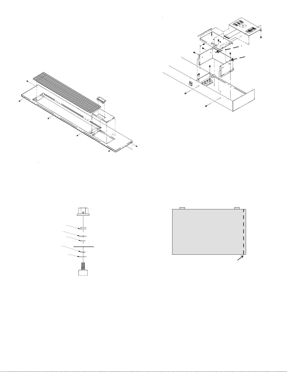
3. Lift the cabinet front off the chassis.
4. Remove the six screws from the top (4 in front and 1 on
each side) and lift the top away.
Figure 7
5. Remove the unit control knob by loosening the setscrew
and pulling the knob off the potentiometer shaft. Also,
remove the nut as well as the metal and rubber washers.
(See Figure 8.)
STEEL WASHER
STEEL WASHER
RUBBER WASHER
RUBBER WASHER
NUT
Figure 8
6. Remove the two screws mounting the control box to the
front of the top assembly and the two screws mounting
the control box to the inside bottom of the top assembly.
(See Figure 9.)
D
Retaining
Holes
Figure 9
7. Pull the potentiometer shaft from the inside of the
control box. Reinstall the washers, nut, and knob onto
the shaft and tape the potentiometer to the inside of the
control box to retain for the future, if needed. No wiring
needs to be disconnected.
8. Reinstall the four screws to attach the control box back
to the top assembly.
9. 5/16” of sheet metal will need to be removed from the
right side of the Remote Escutcheon. Mark the back-
side of the escutcheon with a straight edge and use a
pair of tin snips to remove 5/16” of the right edge of
material. (See Figure 10.)
Cut Here
THIS UNIT IS CONTROLLED BY
WALL MOUNTED THERMOSTAT
Figure 10
10. Place the new escutcheon on the control cover by
inserting the tabs at the top of the escutcheon into the
retaining hole and laying the escutcheon flat on the
membrane pad.
11. Reinstall top by replacing the screws removed in Step
4.
12. See steps 15 and 16 on Page 3.
13. Reinstall the front removed in Step 3.
14. Apply power and, using the wall mounted thermostat,
check for correct operation.