Loading ...
Loading ...
3
12. Pull the potentiometer shaft from the inside of the control
cover. Reinstall the washers, nut, and knob onto the shaft
and store for reinstallation should the use of the wired
thermostat be discontinued.
13. Reinstall the control cover and two screws removed in
Step 9.
14. Place the new remote escutcheon on the control cover by
inserting the tabs at the top of the escutcheon into the
retaining holes and laying the escutcheon flat on the
control panel on top of the touch pad, if present.
15. Remove 14-pin or 18-pin female housing from control
board.
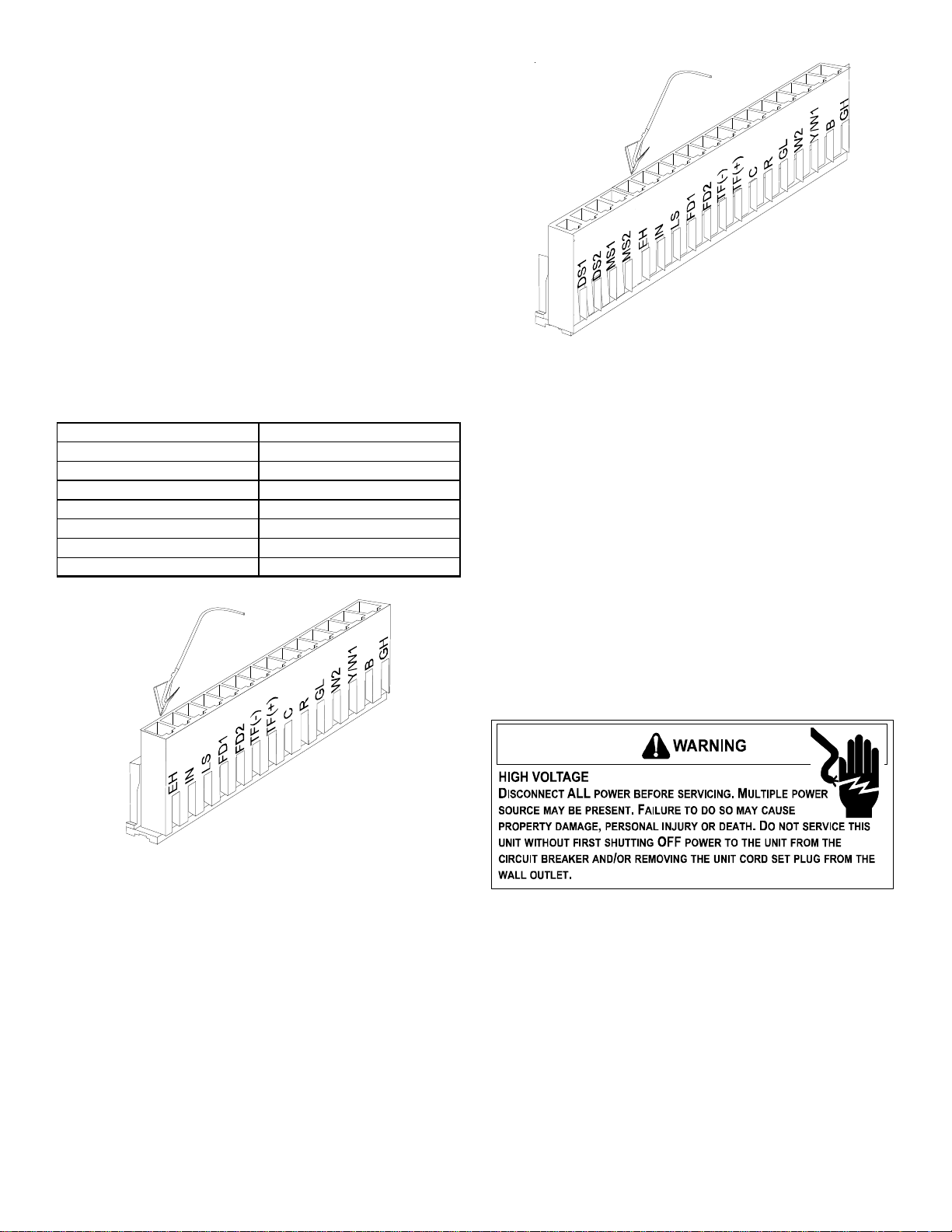
Using the Table below and Figures 5 and 6 as guides,
choose the feature desired and insert the proper jumper
wire into the appropriate slot on the housing. Ensure the
jumper wires are oriented as shown.
NOTE: The options of wired energy management devices
(door switch & motion sensor marked with an (* ) asterisk)
cannot be used with a wired thermostat.
Feature Pins Used
Emergency Hydronic Heat EH, IN
Load Shedding LS, IN
Front Desk Control FD1, FD2
Transfer Fan TF(-), TF(+)
Remote Thermostat C, R, GL, W2, Y/W1, B, GH
*Motion Sensor MS1, MS2
*Door Switch DS1, DS2
Figure 5 - 14 Pin Housing
Figure 6 - 18 Pin Housing
Reinstall the 14-pin or 18-pin housing. Ensure housing
faces the direction shown.
NOTE: Only load wires intended for installation. Extra
wires can be used to connect other PTAC boards.
16. Connect the kit wiring to the field wiring using the wire nuts
provided. Route the kit wiring as shown in Figure 4. Do
not run wires through basepan or wall sleeve.
17. Replace the front by reversing steps 1 through 4.
Installation Instructions
TOUCH PAD WITH KNOB INSTRUCTIONS
FOR HYDRONIC UNITS
(Hydronic units only)
1. Configure for wired thermostat control.
If the unit is being controlled by a wired wall thermostat, the
board should have been configured to allow the thermostat
to operate the unit. If thermostat is being installed, config-
ure control for a wired wall thermostat, press and hold the
FANSPEED button and press the COOL button twice. The
light in the bottom left hand corner below the OFF light will
blink twice to confirm that the configuration was success-
ful. Repeat this step if the light did not blink.
Loading ...