Loading ...
2
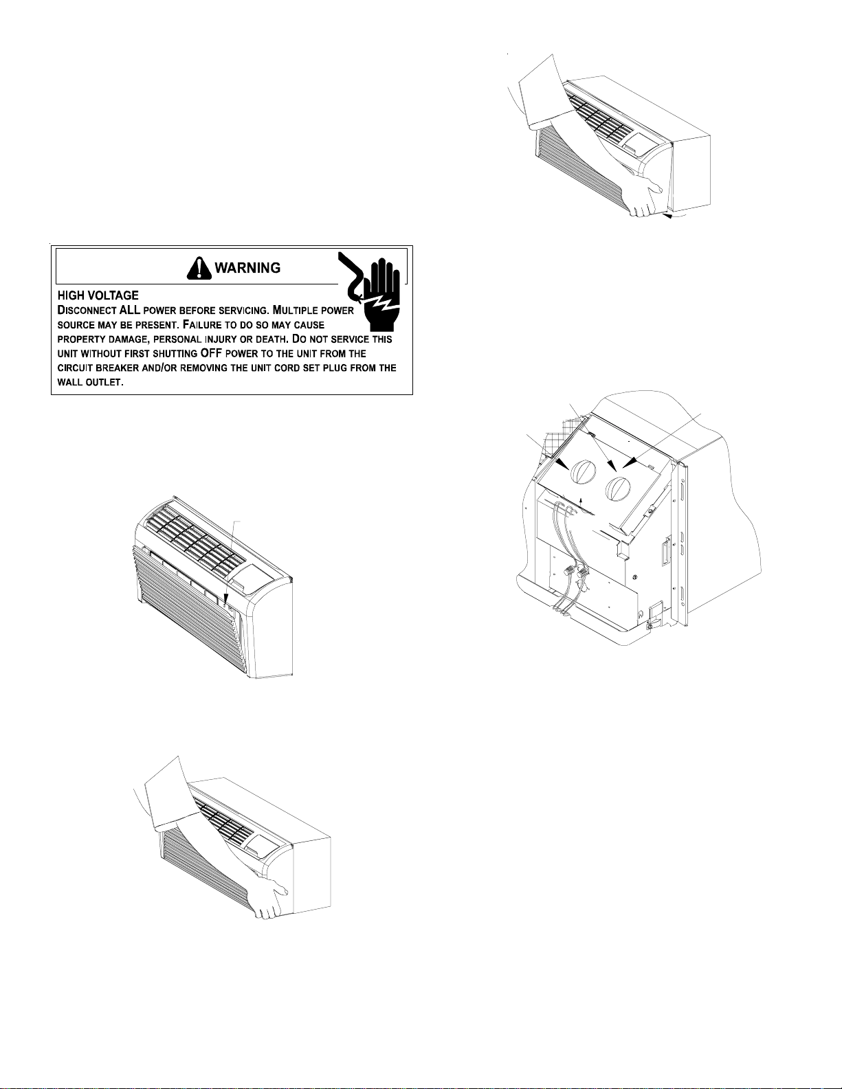
Figure 3
5. Lift the cabinet front off the chassis. If the unit has
standard touch pad controls, go to Step 14. If the unit has
standard knob pad controls, go to Step 9.
6. For units with (2) knob escutcheon, remove the unit
control knobs by pulling the knobs off the control shafts.
PULL TO REMOVE
THERMOSTAT KNOB
PULL TO REMOVE
MODE SWITCH KNOB
ESCUTCHEON
Lift Off
Figure 4
7. Lifting the front edge of the escutcheon, slide the tabs at the
top of the escutcheon out of the retaining holes and remove
the escutcheon.
8. Store the control knobs and escutcheon just removed from
the unit for reinstallation if the wall thermostat is no longer
used. Go to Step 14.
TOUCH PAD WITH KNOB INSTRUCTIONS
FOR ALL STANDARD UNITS
(Non-hydronic units)
9. Remove the two screws holding the control cover to the
chassis, and fold the control cover forward.
10. Unplug the orange potentiometer wires from the IHD /
Orange terminals on the control board.
11. Remove the unit control knob by loosening the setscrew
and pulling the knob off the potentiometer shaft. Also,
remove the nut as well as the metal and rubber washers.
1. Disconnect power.
2. Remove the screw located behind the inlet grille. Pull the
inlet grille forward from the top of the grille to access two
screws.
FRONT MOUNTING
HOLE
Figure 1
3. Grasp the cabinet front as shown.
`
Figure 2
4. Pull the bottom of the cabinet front away from the chassis
until the retaining clips disengage.
Installation Instructions
INSTALLER NOTE: Before proceeding, determine the type
controls you have from examples shown on page 1.
FOR STANDARD (2) KNOB ESCUTCHEON, STANDARD
TOUCH PAD OR STANDARD KNOB PAD ON A NON-
HYDRONIC UNIT, SEE INSTRUCTIONS BELOW.
FOR STANDARD KNOB PAD FOR USE ON HYDRONIC
MODELS, SEE PAGE 3.
Loading ...
Loading ...