Page 1
USA
R
Low Impact Climber
with Pulse*
Owner’s Manual
Assembly and Operation
*Several versions of this owner’s manual exist. This
is a copy of the last version published. If the
assembly instructions do not coincide with your
718e, please call Precor Customer Service.

Page 2
Thank you for purchasing the Precor 718e or 723e Low Impact Climber with
Pulse. The pulse feature lets you view your pulse rate on the display when you
use the Precor pulse detector (ear clip option) or the Precor Heart Rate Option.
The smooth, quiet motion of the stair arms lets you focus on your workout
without the noise and distractions other climbing machines have. Multiple
resistance settings let different users set the machine to their workout demands
and allow workload to be raised and lowered within a single session. The unique
handrails offer a number of handhold positions to lend variety to a workout. The
low-impact exercise tones all the muscles in the lower body while helping to
build your cardiovascular fitness level.
The 718e Low Impact Climber provides microprocessor-controlled electronics
which let you monitor your progress and keep your workouts interesting.
Safety Information
Please review and observe the following safety guidelines:
• Read the Owner’s Manual and follow all instructions.
• Assemble and operate the climber on a solid, level surface.
• Never allow children on or near the climber.
• Check the climber before each use. Do not use the climber if it is not
completely assembled or is damaged in any way.
• Keep hands away from moving parts.
• Be aware that the weight limit for the climber is 250 pounds.
• Wear proper exercise clothing and shoes for your workout—no loose
clothing. Do not wear shoes with heels or leather soles. Check the soles of
your shoes and remove any dirt and embedded stones. Tie long hair back.
• Use care when getting on or off the climber. Do not rock the unit. Do not
stand or climb on the handrails and electronic console.
• Do not use accessory attachments that are not recommended by the
manufacturer—such attachments might cause injuries.
• Be aware that, under extended continuous use, the resistance cylinders on
the climber can heat up to the point of being uncomfortable to touch.
• Do not overexert yourself or work to exhaustion.
• Stop your workout immediately if you feel any pain or abnormal
symptoms, and consult your physician.
Low Impact
Climber with
Pulse
USA
R
CAUTION: Before beginning
any fitness program, you
should have your physician
give you a complete physical
examination.

Page 3
Table of Contents
Unpacking the 718e Low Impact Climber................................................ 4
Assembling the 718e Low Impact Climber.......................................... 6
Installation Requirements.................................................................... 6
Assembly Instructions......................................................................... 6
Using the Precor 718e Low Impact Climber.............................................. 16
Understanding the Electronic Console................................................. 16
Displays............................................................................................ 16
Keys................................................................................................. 17
Setting the Resistance Level................................................................ 18
Setting a Pacer.................................................................................... 19
Using the Pulse Feature....................................................................... 19
Pausing Your Workout........................................................................ 20
Ending a Workout................................................................................ 20
How to Use the 718e Climber ............................................................. 20
Working Out on the 718e Climber ..................................................... 20
Sample Exercise Routines................................................................... 22
General Aerobic Training Information....................................................... 23
How Hard Should I Exercise?.............................................................. 24
How Long Should I Exercise?.............................................................. 25
How Often Should I Exercise?............................................................. 25
Maintenance and Troubleshooting............................................................ 26
Cleaning the Climber........................................................................... 26
Changing the Batteries......................................................................... 26
Troubleshooting Tips........................................................................... 27
Obtaining Service................................................................................ 27
Page 4
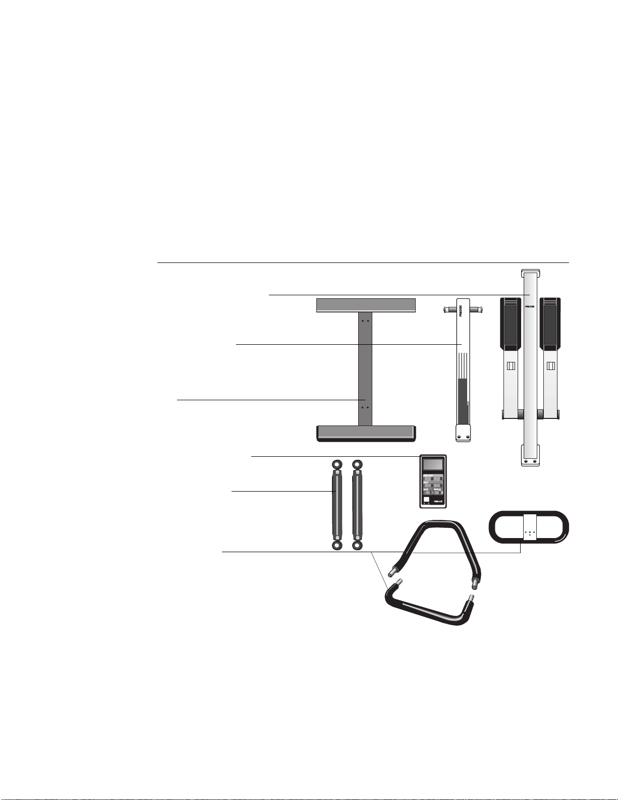
Unpacking the 718e Low Impact Climber
All Precor products are thoroughly tested and inspected before shipment. The
718e Low Impact Climber is shipped in the following pieces:
• base
• upright support (long column)
• base column support (short column)
• resistance cylinders
• handrail console
• electronic console display
• hardware kit, Owner’s Manual, and limited warranty card (not shown in
Diagram 1)
718e
718e
USA
R
USA
R
USA
R
Resistance cylinders
Base
Diagram 1
Unpacking the climber
Upright support (long column)
Base column support
(short column)
Handrail consoles
Electronic console display
Unpack the climber and place all the pieces on the floor. For help in identifying
the various pieces, refer to Diagram 1. The packet containing the hardware kit,
Owner’s Manual, and limited warranty card is not shown.
Important: Do not pinch or crimp the reed switch cable during the unpacking
and assembly process. The rope attached to the 718e upright assembly is used
to install the reed switch cable. Do not remove the rope from the 718e upright
assembly at this time. Do not cut the wire ties holding the stair arms to the
upright support.
Page 5
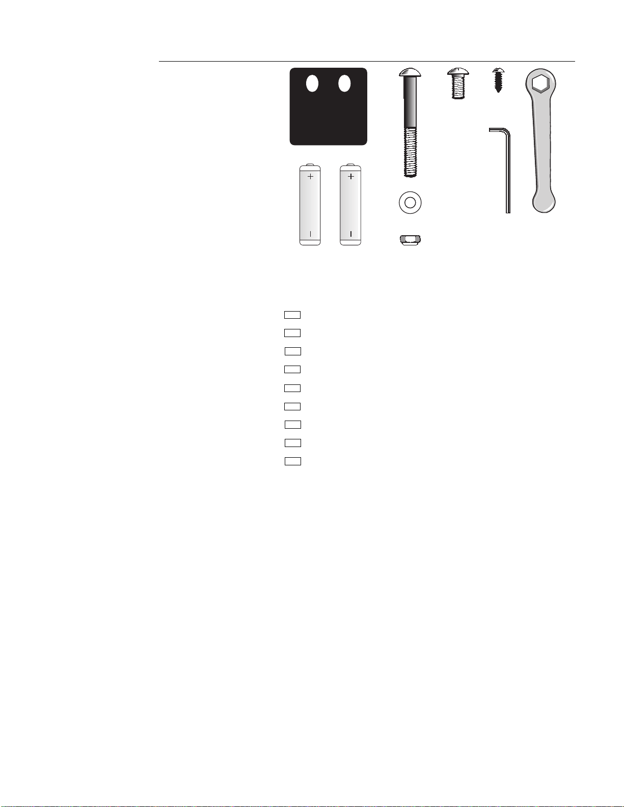
Open the hardware kit and identify the following items. Diagram 2 provides an
overview of the kit’s contents. As you identify the contents of the kit, check them
off below:
(A) Two gaskets for frame base
(B) Four frame-to-base bolts
(C) Four large flat washers
(D) Four lock nuts
(E) Two small bolts
(F) Two phillips-head screws
(G) One 3/16" hex key
(H) One 1/2" wrench
(I) Two AA batteries
If any items are missing, contact your authorized Precor dealer. For the dealer
nearest you, call 1-800-4-PRECOR.
B
Diagram 2
718e Hardware kit
G
H
D
C
E
F
A
I
Page 6
Assembling the 718e Low Impact Climber
The information in this section provides instructions regarding the assembly of
the 718e or 723e Low Impact Climber. You should carefully read and follow the
instructions in this manual. If you do not assemble and use the climber
according to the following guidelines, you could void the Precor limited
warranty.
Installation Requirements
Follow these installation requirements when installing the climber:
• Set up the 718e climber on a solid, flat surface.
• Fill out and mail the limited warranty registration card. The serial number
is located on the underside of the climber’s base. It is also located on a
label on the outside of the box.
Assembly Instructions
To assist you in the assembly of the 718e climber, the items in the
hardware kit, shown in Diagram 2, correspond to a particular letter in the
alphabet. These letters appear throughout the assembly instructions. Refer to
Diagram 2 while performing the steps below.
Note: You will need a scissors and a phillips-head screwdriver to complete the
assembly process.
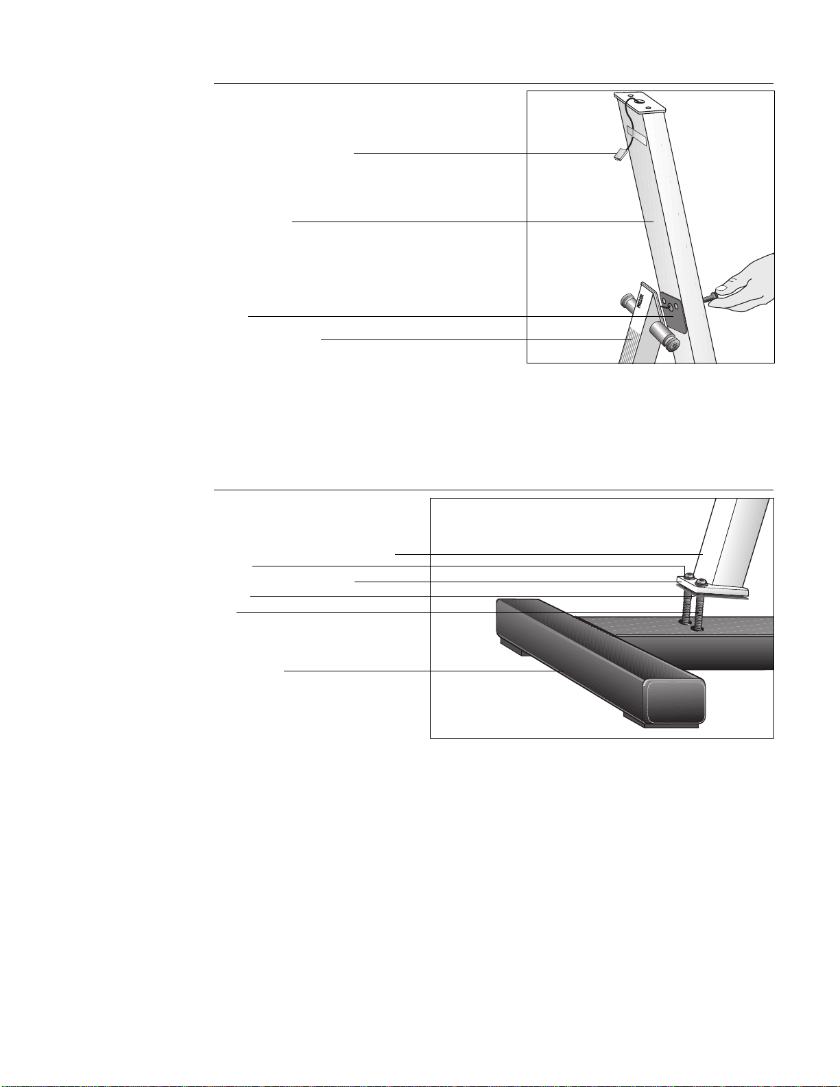
Diagram 3
Place frame on base
1. Place Upright Support on Base. (Diagram 3) To install the upright support
(long column that has the stair arms attached) take the following steps:
Important: Do not remove the red rope from the upright support. It is used
to feed the reed switch cable through the upright support.
a. Place the base at or near the location where you will be using the
climber. Lift the base onto wooden blocks or large hardcover books.
This helps you access the underside of the base. Make sure that the
rubber pads on the crossbar are facing the floor.
b. Position the upright support (long column) onto the base.
Note: Be sure to align the upright support and base properly. The
front crossbar and upright support mounts are very close together as
shown in Diagram 3.
Upright support
Stair arm
Front crossbar
Base
Blocks or books
Page 7
c. Remove a gasket (A) from the hardware kit. Align the upright support
with the mounting holes in the base. Place the gasket between the
upright support mount and base.
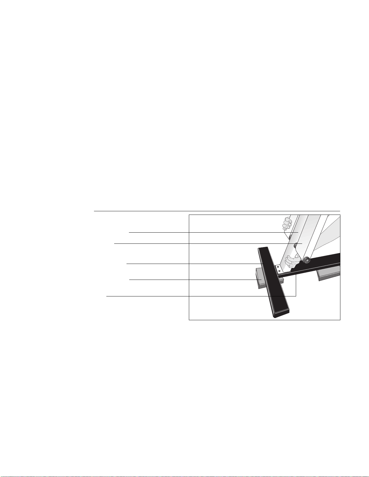
Diagram 4
Attach frame to base
Front crossbar
Bolt
Upright support
Base
Weld
Gasket
Washer
CAUTION: To avoid injury and
ensure the integrity of the
unit, do not drop the stair arm
onto the rear crossbar.
d. Take two frame-to-base bolts (B) from the hardware kit and place a
washer (C) on each. Insert the bolts through the upright support
mount, gasket, and base. Make sure that the front mount is adjacent
to the crossbar weld, but not on top of the weld. See Diagram 4.
Attach a lock nut (D) to the opposite end of each bolt. Hold the lock
nut with the socket wrench while you firmly tighten the bolts with the
hex key (G) provided.
Important: Perform the following step on one stair arm at a time.
e. Hold onto the stair arm’s footpad with one hand while you use
scissors (in the other hand) to cut the plastic wire tie that secures the
stair arm to the upright support. Carefully lower the stair arm onto the
rear crossbar. Perform the same step for the other stair arm.
Note: If the upright support is mounted properly, the stair arms rest
on the
rear
crossbar.
Page 8
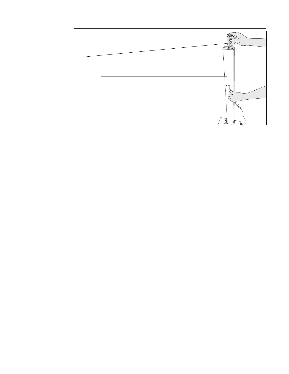
Rope
Upright support
Diagram 5
Pull reed switch cable through
upright support
Reed switch cable
Reed switch cable connector
2. Feed Reed Switch Cable through Upright Support. (Diagram 5) Remove
the bolts from the base column support (short column) and set them
aside. The gasket should hang on the reed switch cable. Take the following
steps to install the reed switch cable:
a. Cut the wire tie from around the reed switch cable and gently pull the
cable out of the roller guard. Place the short column near the upright
support so that the gasket and roller guard face the red rope.
b. Ask an assistant to hold the base column support. This lets you have
both hands free to manipulate the rope and cable.
c. Securely tape the reed switch cable connector to the
end
of the red
rope and feed the cable through the upright support (long column) as
you carefully pull the rope out from the top. Tape the reed switch
cable to the top of the upright support and set the rope aside for use
in step 12.
Note: You may need to tip the climber onto its side if the cable
disengages from the rope. A hex key is helpful in locating the cable
inside the column and in pulling it through the hole at the top.
Page 9
718e
USA
R
Reed switch cable connector
Upright support
Diagram 6
Attach base column support to
upright support
3. Secure Upper Frame Pieces Together. (Diagram 6) Gently pull the reed
switch cable from the top of the upright support as you align the bolt holes
in the upright support with the base column support and gasket. Insert the
two mid-frame bolts that you set aside in step 2. Thread the bolts through
the upright support and into the short column. Fully tighten the bolts using
the hex key (G) provided, but be careful not to pinch the cable.
CAUTION: Make sure you do
not crimp the reed switch
cable when you tighten the
base column support onto the
upright support because you
could void the manufacturer’s
limited warranty.
Gasket
Base column support
(short column)
Diagram 7
Install base column support to
base frame
4. Attach Base Column Support to Base. (Diagram 7) Place a washer (C)
onto each of the two remaining frame-to-base bolts. Place the remaining
gasket between the base column support mount and the base frame. Align
the holes and insert the bolts and washers through the base column
support mount and the climber base. Attach a lock nut (D) to the end of
each bolt. Hold the lock nut with the wrench (H) while you firmly tighten
the bolts with the hex key (G) provided.
Base column support (short column)
Washer
Base column support mount
Gasket
Bolt
Rear crossbar
Page 10
1
3
2
4
5
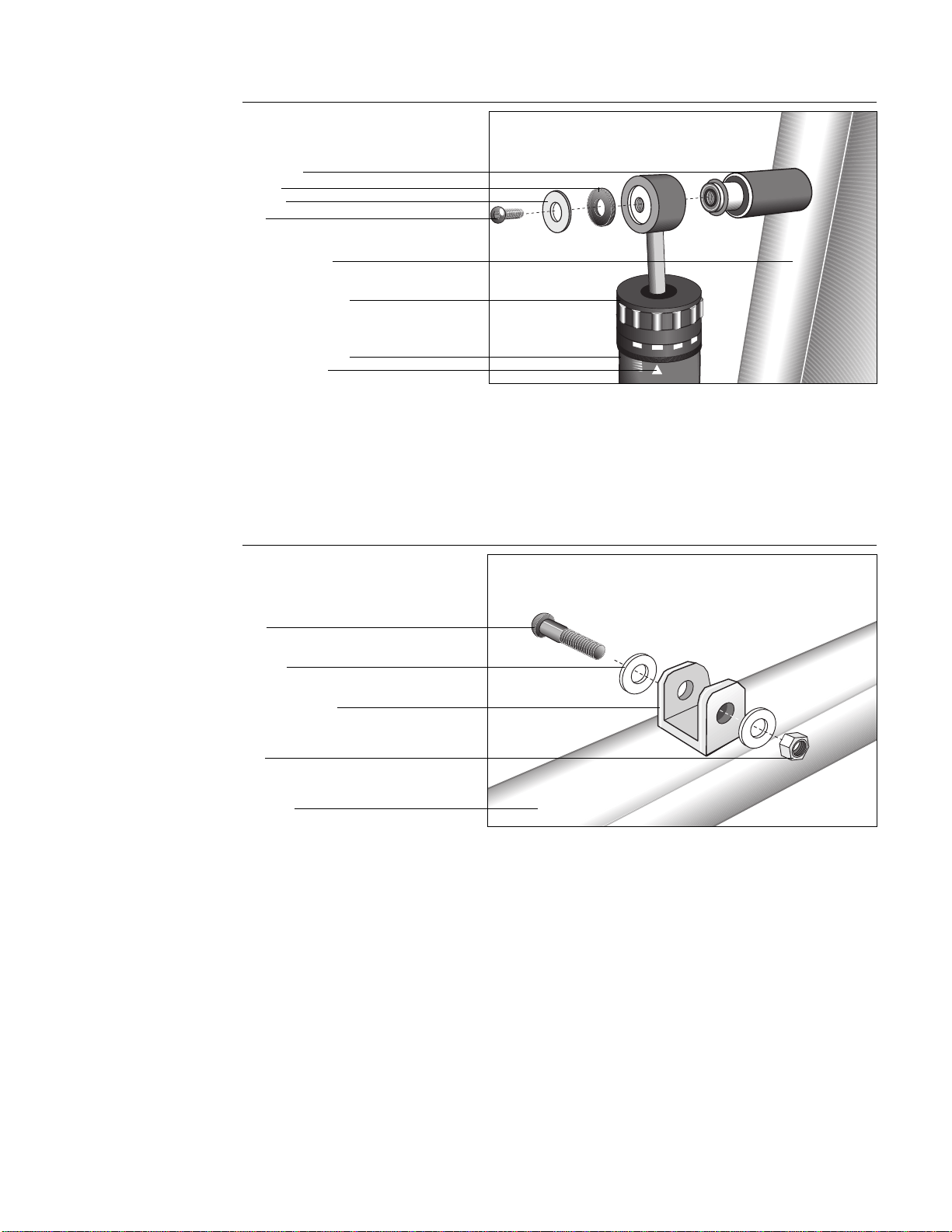
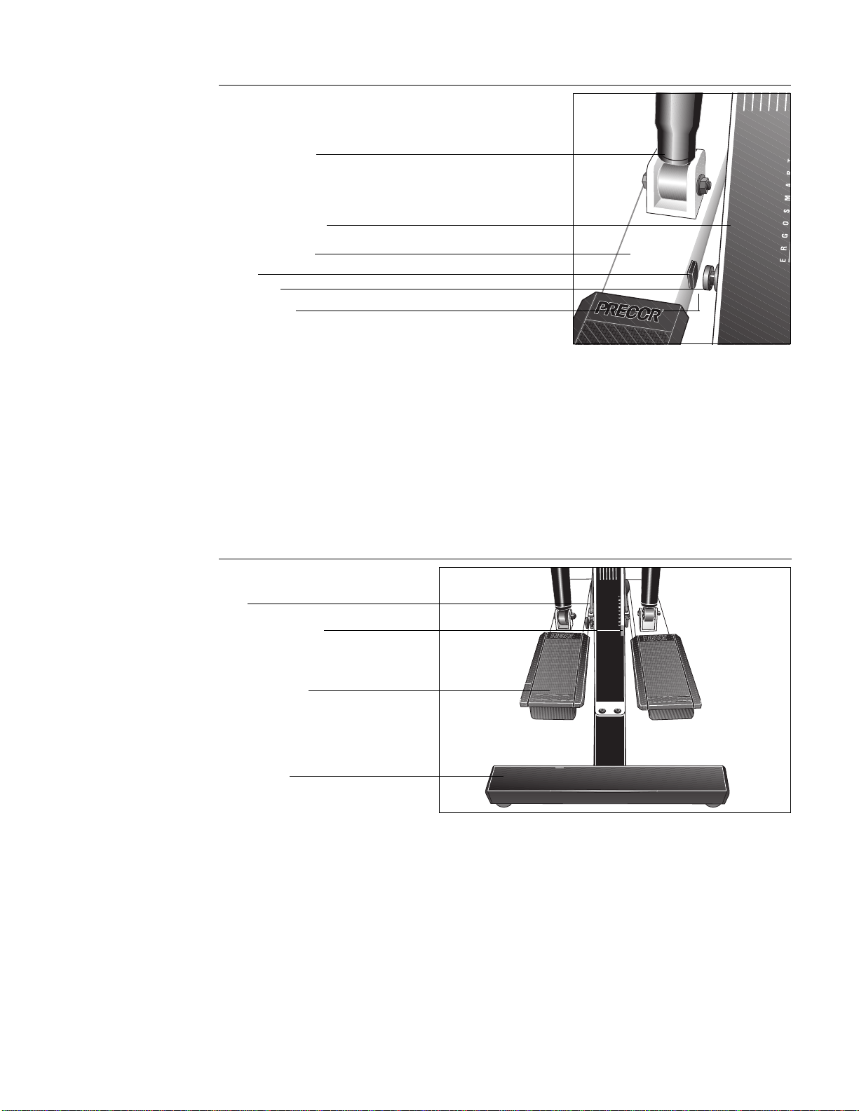
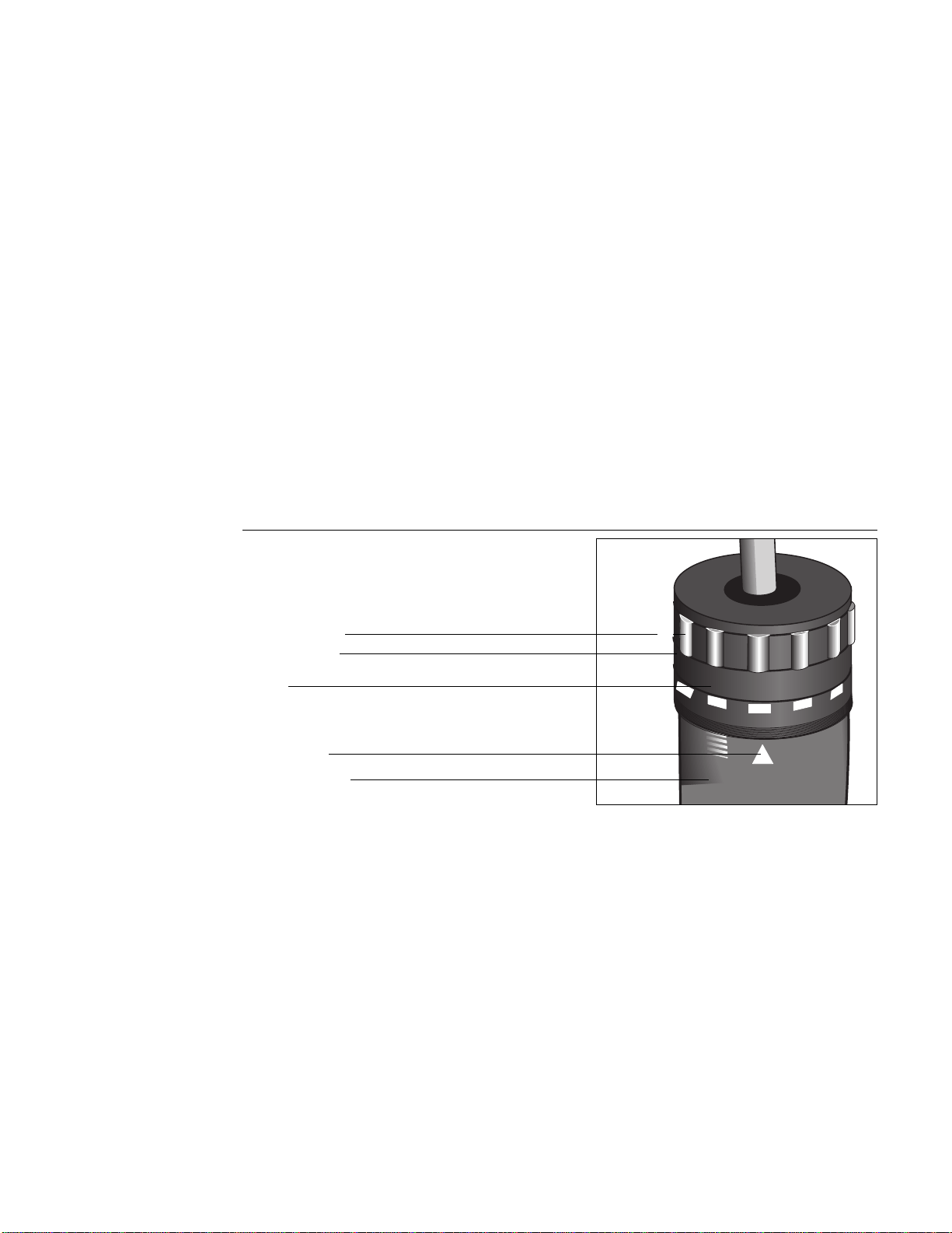
5. Attach Resistance Cylinders to Upright Support. (Diagram 8) Remove the
bolt, washer and spacer from the upper axle using your fingers or the hex
key (G) provided. With the indicator arrow facing toward the footpad, slide
the top of the resistance cylinder onto the upper axle. Place the washer and
spacer on the bolt. Re-insert the bolt and tighten securely using the hex
key provided. Repeat this same step to attach the other resistance cylinder.
Adjustment portion
Upright support
Indicator arrow
Resistance cylinder
Diagram 8
Attach resistance cylinder to
upright support
Bolt
Washer
Spacer
Upper axle
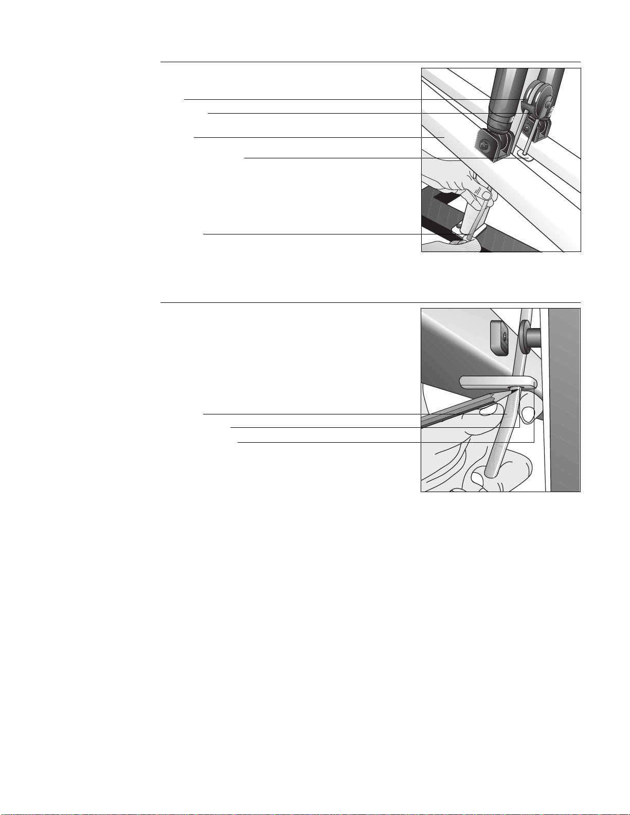
Diagram 9
Remove bolts from lower
resistance cylinder mounts
6. Connect Resistance Cylinders to Stair Arms. (Diagrams 9 and 10) The
washers, nut, and bolt need to be removed from the lower resistance
cylinder mount (U-shaped mount) before connecting the resistance
cylinders. See Diagram 9. Remove the bolt using your fingers or the
supplied hex key (G). To mount the lower resistance cylinders to the stair
arms, take the following steps:
Note: Perform the following steps on one stair arm at a time.
U-shaped mount
Stair arm
Bolt
Washer
Nut
Page 11
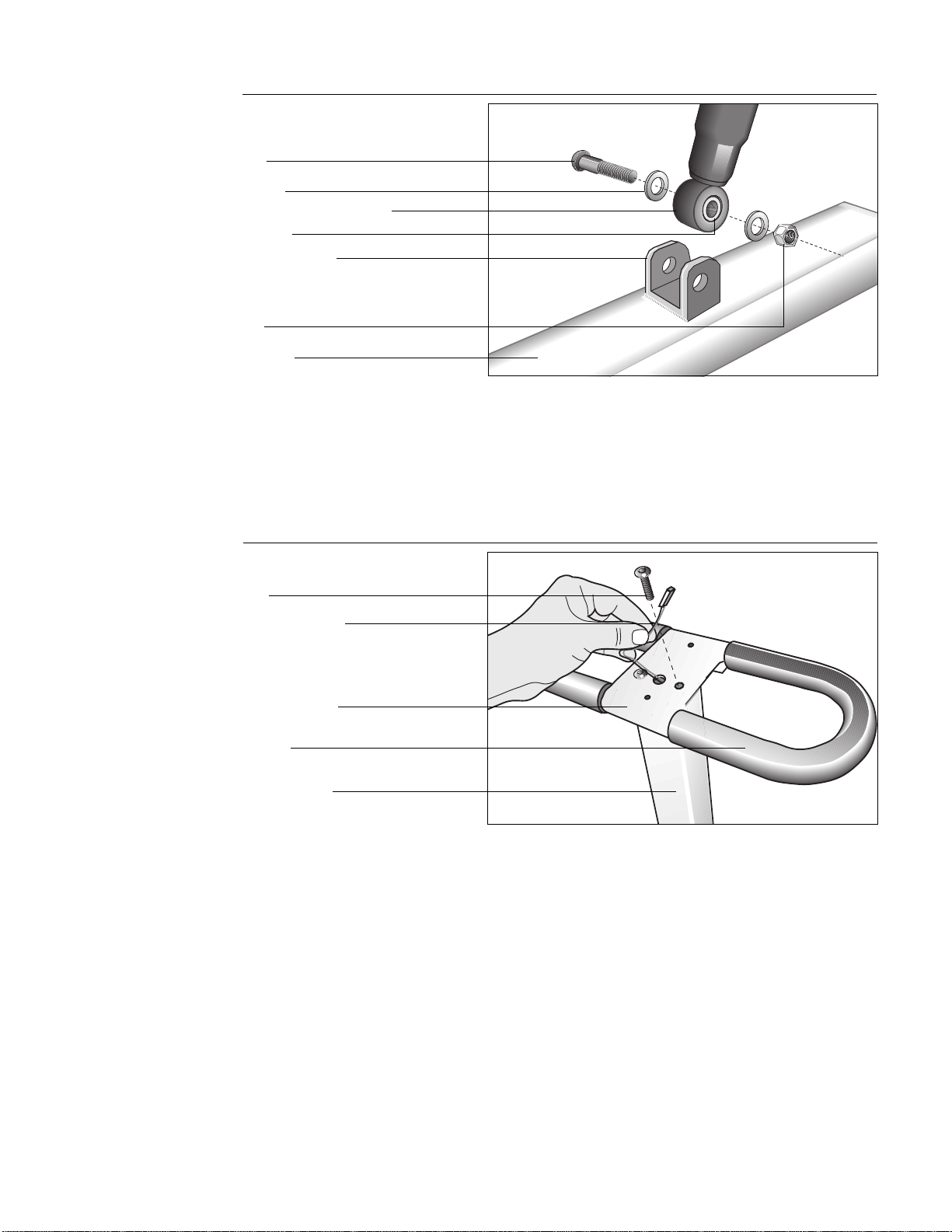
Diagram 10
Attach resistance cylinder to stair arm
Bolt
Stair arm
Nut
a. Align the resistance cylinder with the holes in the U-shaped mount
and slide the resistance cylinder into position. See Diagram 10.
b. Insert the bolt through the U-shaped mount and resistance cylinder as
shown in Diagram 10. Use the wrench to hold the nut in place while
you tighten the bolt securely.
c. Repeat step 6 to mount the other resistance cylinder.
Resistance cylinder mount
Washer
Bushing
U-shaped mount
Diagram 11
Install handrail
Handrail console
Handrail
Upright support
CAUTION: The reed switch
cable should slide easily
through the upright support.
Do not tug on the cable
because you could void the
manufacturer’s limited
warranty.
7. Install Handrail. (Diagram 11) Take the two small bolts from the hardware
kit. Position the handrail console (flat surface of the console should face
up) on top of the upright support and feed the reed switch cable through
the large hole in the handrail console. Tape the connector to the top of the
console. Align the bolt holes and secure the handrail console to the frame
by inserting the bolts through the top of the handrail console and into the
upright support. Tighten the bolts firmly using the hex key (G).
Important: Pull gently on the excess cable as you feed the cable through
the large hole in the handrail console. If the cable does not move freely,
check to be sure that the cable is not pinched or crimped between the long
and short column mounts. See step 3.
Bolt
Reed switch cable
Page 12
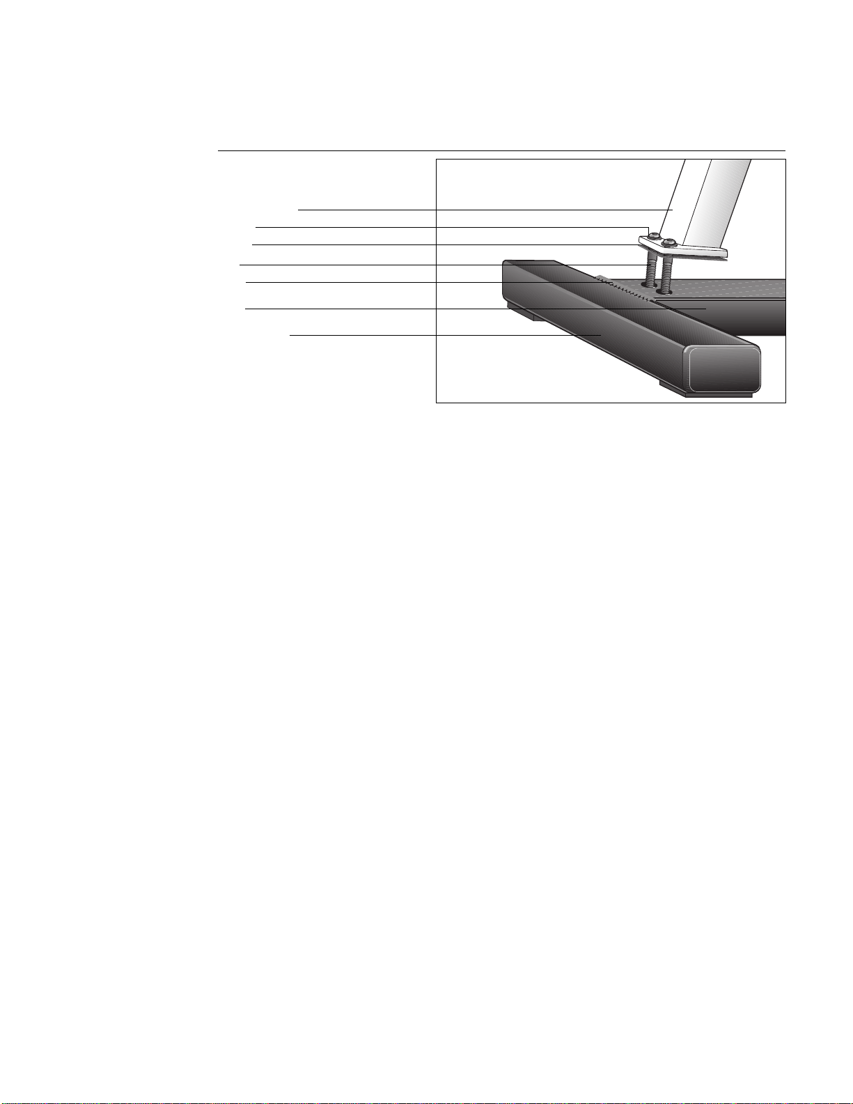
Diagram 12
Install electronic console
Phillips-head screws
Electronic console
8. Install Electronic Console. (Diagram 12) To attach the electronic console
display to the handrail console, take the following steps:
a. Plug the slotted reed switch cable connector into its receptacle on the
underside of the electronic console display.
b. Place the electronic console display on the handrail console while you
gently feed any excess cable back through the hole in the handrail
console.
c. Align the holes and insert two phillips-head screws (F) on the
underside of the handrail console.
d. Tighten the screws using your phillips-head screwdriver.
Handrail console
CAUTION: Make sure you do
not crimp the reed switch
cable when you tighten the
base column support onto the
upright support because you
could void the manufacturer’s
limited warranty.
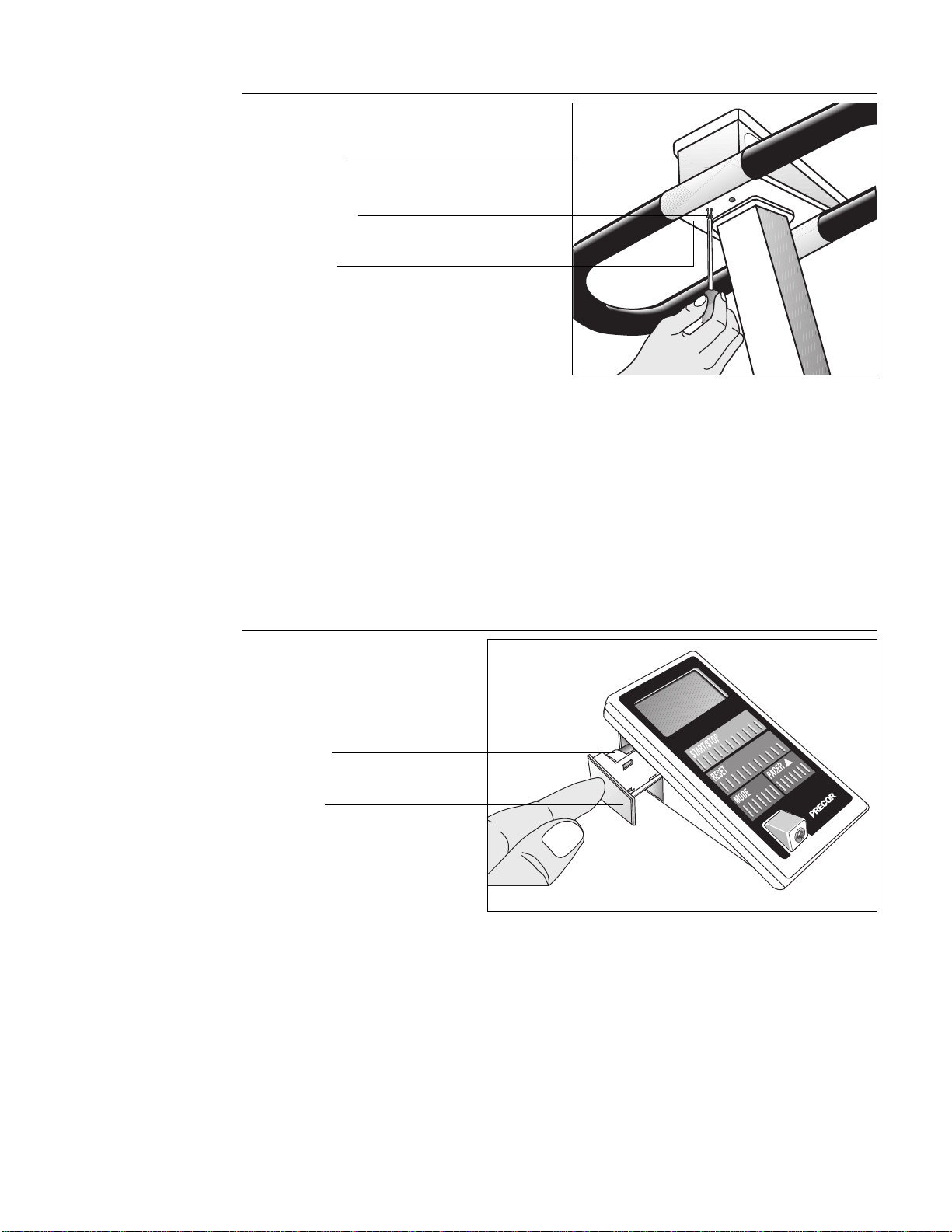
Diagram 13
Install the batteries
USA
R
9. Insert Batteries. (Diagram 13) Find the drawer on the side of the electronic
console and press in lightly to open it. Pull the drawer out with your
fingers. Take the following steps to insert the batteries:
a. Slide the drawer out to expose the battery case. Place the two “AA”
alkaline batteries (found in the hardware kit) into the case. Align the
batteries to the proper polarity (+ and - indicators are inside the
battery case). The entire display lights and the console beeps.
b. Close the battery drawer by pushing it gently into the electronic
console.
c. Press START/STOP to activate the timer (TIME display). Press RESET
to “reset” the displays to zero. For more information, refer to the
section titled,
Understanding the Electronic Console.
Battery drawer
AA battery case
Page 13
USA
R
USA
R
USA
R
Diagram 14
Location of magnet and reed switch
Left-hand stair arm
Resistance cylinder
Base column support
Magnet
Reed switch
10. Check Operation of Electronics. (Diagram 14) Make sure that the spacing
between the magnet on the left stair arm and the reed switch on the rear
short column is correct. If the spacing is incorrect, the electronic console
display will not operate properly. The distance between the magnet and the
reed switch should be about 1/8 inch (.05 centimeters). If the spacing is
not correct, adjust the spacing by moving the reed switch in or out of the
column with your fingers.
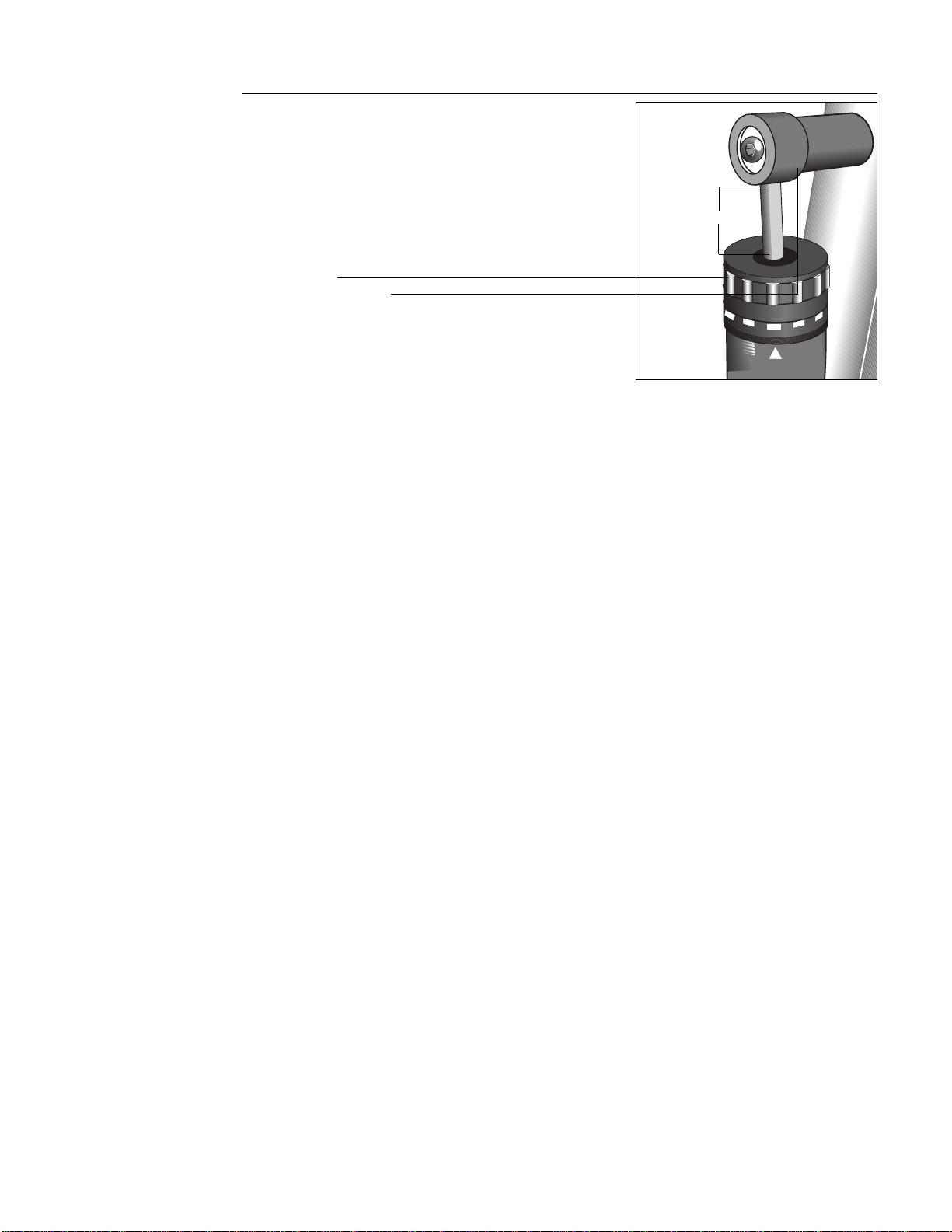
11. Set the Resistance. Adjust the stair arm resistance by turning the top of
the resistance cylinder until the triangle on the resistance cylinder points to
the “2” on the adjustment knob. Do the same for the other stair arm. Make
sure that the resistance on both stair arms is at the same setting.
Diagram 15
Align stair arms with label
12. Install Rope. (Diagram 15 and 16) To properly install the rope (set aside in
step 2), get a marker (pen or pencil) and take the following steps:
a. Feed the rope up through the right stair arm mount. (Determine right
and left while standing behind the rear crossbar and facing toward the
electronic console.)
b. Move both stair arms so that the
top
of the stair arms line up with the
red box located on the Precor label. See Diagram 15. Have an
assistant hold the stair arms in place while you route the rope through
the pulley.
Note: It may be easier to install the guide rope if the climber is placed
on its right hand side on the floor. This will expose the underside of
the stair arms and provide easier accessibility.
Precor label’ red box
Stair arm footpad
Rope
Gap 1/8" to 1/4"
(.05 to .1 centimeters)
Rear crossbar
Page 14
c. Loop the rope over the pulley (through the finger guard on both sides
of the pulley) and down into the left stair arm mount. See Diagram 16.
Guide rope
Diagram 16
Install the guide rope
Stair arm
Pulley
Pencil or pen mark
Guide rope
Diagram 17
Mark the guide rope
d. Pull the rope taunt and mark the rope where it meets the stair arm
mount. See Diagram 17.
Important: Before you mark the rope, be sure that the top of both stair
arms line up with the top of the red box on the Precor label. Refer to
Diagram 15 on page 13.
d. With the rope running through the stair arm mount, move both stair
arms up so that you can easily tie a knot where you marked the rope.
Note that if you placed the climber on its side to install the rope,
return the climber to an upright position with the base flat on the
floor.
e. Check the length of the guide rope by returning the stair arms to an
even position shown in Diagram 15 on page 13. The top of both stair
arms should line up with the red box located on the Precor label.
f. Step onto the stair arms. Test the stair stroke by moving your legs up
and down a few times.
CAUTION: Do not stand on
the stair arms while
performing these steps. Prior
to working out, the tension on
the guide rope must be set
properly to avoid damaging
the resistance cylinders and
voiding the manufacturer’s
limited warranty.
CAUTION: Check the knots
and the length of the rope
before standing on the stair
arms. You cannot re-tie the
knots once you stand on the
stair arms.
Finger guard
Right stair arm mount
Left stair arm mount
Page 15
1
3
2
4
5
Diagram 18
Measure the distance of the
resistance cylinders from the
mounts
1/4" to 1/2"
Adjustment knob
Resistance cylinder mount
g. Press the right footpad down onto the rear crossbar. Let the left stair
arm move up into its highest position (away from the rear crossbar).
Check the distance between the top of the resistance cylinder on the
left stair arm and the upper axle. It should be between 1/4 to 1/2
inches (.1 to .2 centimeters). See Diagram 18. If the distance is
correct, you have installed the rope properly. If the adjustment knob
touches the resistance cylinder mount, you will need to replace the
rope and readjust the length.
Note: To obtain a new rope call your local Precor dealer at 1-800-4-
PRECOR.
Every time you use your climber, make sure that all frame-to-frame and frame-
to-base bolts are still tight. If there is any movement, firmly re-tighten all bolts.
Page 16
Using the Precor 718e Low Impact Climber
In addition to providing an excellent cardiovascular workout, one of the
advantages of the 718e climber is that it is simple to use. With very little time or
practice, you can learn how to use it effectively. This section provides informa-
tion and instructions about the following:
• using the electronic console
• setting the resistance level
• setting a pacer
• pausing your workout
• ending a workout
• exercising on the climber
• sample exercise routines
Understanding the Electronic Console
Once you have assembled your 718e climber, it is ready to use. There are no
complex instructions to follow or mandatory programming steps required to
operate the climber—the electronic display is there only for reference. It
provides motivating feedback about your workout to help you monitor your
progress and meet your fitness goals.
The console’s convenient “hands free” function lets you start and end a workout
without touching any keys. Simply start using the climber to begin your
workout. The displays automatically appear and begin providing information
about your workout. To select a specific informational display, such as TIME or
TOTAL STEPS, press the MODE key until the desired information appears on the
display.
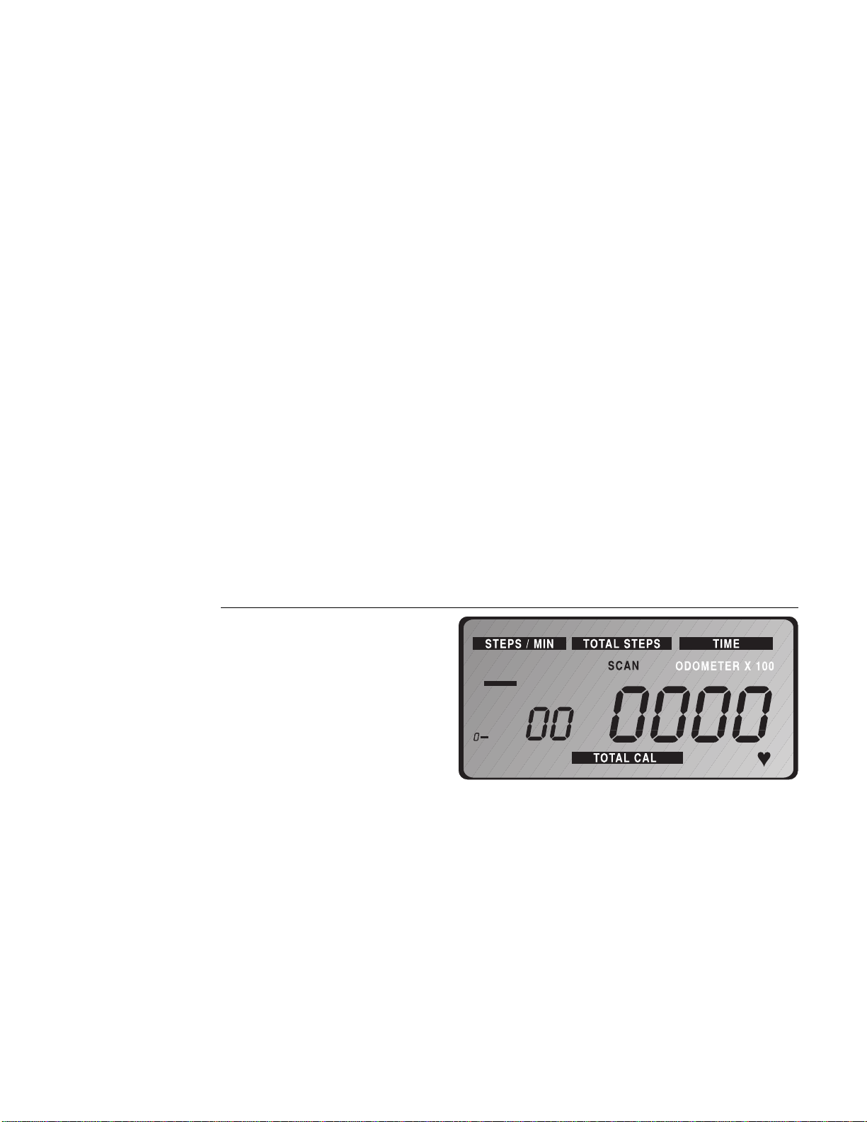
Diagram 19
718e electronic console display
Diagram 19 shows the 718e electronic console display. An explanation of the
eight display features and four keys are explained below.
Displays
STEPS/MIN—appears as the smaller numeric display to the left of the main
numeric display and indicates your steps per minute, up to 99. The bar graph on
the left side of the display can also provide similar information (up to 150
steps—see
Setting a Pacer
), if you have not set a pacer.
Note: If the display remains at zero when you move the stair arms, check that
the reed switch along the left side of the short column is correctly aligned. Refer
to step 10 in the
Assembly Instructions
.
TOTAL STEPS—shows the total number of steps during a workout, up to a total
of 9,999. You can use this display to measure
total work
accomplished in a
workout.

Page 17
ODOMETER X 100—indicates the total number of steps accumulated on the
climber over time, up to 999,900. This display appears with the TOTAL STEPS
display. Use the odometer to track the amount of “mileage” your climber has on
it. Note that you need to multiply the number that appears by 100.
TIME—functions like a stopwatch, giving you total exercise time per session, up
to 59 minutes and 59 seconds. The TIME display starts or stops automatically
when you start or stop a workout. You must press the RESET key to reset the
TIME display to 0. (For more information about RESET, see the explanation
under
Keys.
) Use the TIME display to keep track of
how long
you have exercised
in a given session.
Note: If you pause during a workout, the internal clock continues to count and
to display the time for another 5 minutes. After 5 minutes, the screen saver
feature takes over, saves your workout statistics, and shuts off the displays. If
you return to your workout before 5 minutes elapse, the time display reverts to
your actual workout time. Refer to
Pausing Your Workout
.
SCAN—alternates between the displays STEPS/MIN, TIME, TOTAL STEPS,
TOTAL CALories, and PULSE every few seconds. When you press the RESET
key or begin a workout by pressing the START/STOP key, the word SCAN
appears on the display and indicates that you are in SCAN mode. If you only
want one particular feature displayed, press the MODE key until the feature is
highlighted. See MODE under
Keys
below.
PACER—appears in the bar graph on the left of the electronic display. You can
select a pacer up to 150 steps per minute. When you maintain or exceed the
pacer’s step rate, the bar stops blinking. The pacer sets a tempo for you to
follow which provides motivation and helps you to maintain your exercise
intensity.
TOTAL CALORIES—displays an estimate of the number of calories being burned
during your workout. The estimate is based on a 150 pound (68 kg) person
working out at your current steps per minute.
PULSE—shows your heart rate if you have installed the Precor receiver
and
put
on a Precor/Polar chest strap or attached the pulse detector (Precor’s ear clip
option) to the console. When you attach the receiver and put on the chest strap
or plug the pulse detector into the console, a
appears on the display at the
bottom right corner.
Keys
START/STOP—starts and stops a workout session. However, the electronic
console automatically begins displaying information when you move the stair
arms. You could use this key to start or stop your workout when you want to
keep your warm-up or cool-down sessions separate from your workout
statistics.
MODE—specifies the information you want displayed; whether its STEPS/MIN,
TIME, TOTAL STEPS, TOTAL CALories, PULSE or SCAN mode. Simply press
this key repeatedly until information from the desired display appears.
PACER—sets a pace tempo. When you press this key the pacer appears in the
bar graph on the left side of the display. To set the pace tempo or change the
current pacer setting, press the PACER key until the desired step rate is
highlighted. Refer to
Setting a Pacer.
RESET—resets the displays on the electronic console to zero. Note that
pressing this key does not reset the ODOMETER display. Using the RESET key is
another way to keep your warm-up or cool-down sessions separate from your
workout statistics.
Page 18
Setting the Resistance Level
Before using the 718e climber, you need to adjust the resistance level.
Resistance, which is related to your body weight and your step height during
the workout, determines your cadence (the number of steps you can take per
minute). The relationship between body weight, step height, and cadence
determines how hard you work during a session.
Understanding the principles covered in
General Aerobic Training Information
starting on page 23 will help you select the appropriate resistance for your
fitness level and personal fitness goals. To achieve your goals, it is important to
use a resistance that allows your heart rate to reach your training zone (see
Diagram 24 on page 24) and then maintains that rate for the desired length of
time—while you maintain a step height between 4 to 8 inches. (For information
about your training zone, see
How Hard Should I Exercise?
in
General Aerobic
Training Information.
)
Keep these guidelines in mind when adjusting the resistance cylinders:
• Resistance settings on the 718e climber range from 1 to 12.
• “1” provides a faster cadence (step rate) due to less resistance in the stair
arms than “12.”
• The resistance cylinders operate more stiffly at the beginning of a workout
until they warm up. You may want to re-adjust the resistance settings after
working out for about 5 minutes.
1
3
2
4
5
Diagram 20
Setting the resistance level
Resistance setting
Adjustment knob
Number
Indicator arrow
Resistance cylinder
To adjust the resistance level, take the following steps:
1. When beginning your workout, warm up by setting the resistance between
1 and 3. Turn the top of the resistance cylinder so that the number aligns
with the arrow. See Diagram 20.
2. Repeat step 1 for the opposite stair arm. Make sure that both resistance
cylinders are set on the same number to ensure equal resistance.
Note: Allow the resistance cylinders to warm up for at least 5 minutes
before raising the resistance setting. After which, you can adjust the
settings anytime during your workout. However, after extended, continu-
ous use, the resistance cylinders can heat up to the point of being
uncomfortable to touch.
Start exercising at a low setting. Gradually work your way to a comfortable
resistance level and into your target heart rate zone (see Diagram 24, page 24).
CAUTION: Make sure that both
cylinders are set at the same
resistance setting to ensure a
smooth, balanced feel during
your workout.
CAUTION: Do not adjust the
resistance cylinders after
extended continuous use
because they can heat up to
the point of being
uncomfortable to touch.
Page 19
START/STOP
RESET
MODE PACER
USA
R
Setting a Pacer
Setting a pace tempo provides motivation and helps you to maintain your
exercise intensity. To set a pacer, press the PACER key until the bar graph
highlights the desired step rate. The bar graph provides incremental markings
every 15 steps (15, 30, 45..., to 150). If you bypass the mark that you want to
set, continue to press the PACER key. It will cycle around to zero and you can
start over. Note that the pacer stops blinking when you maintain or exceed the
pacer’s step rate.
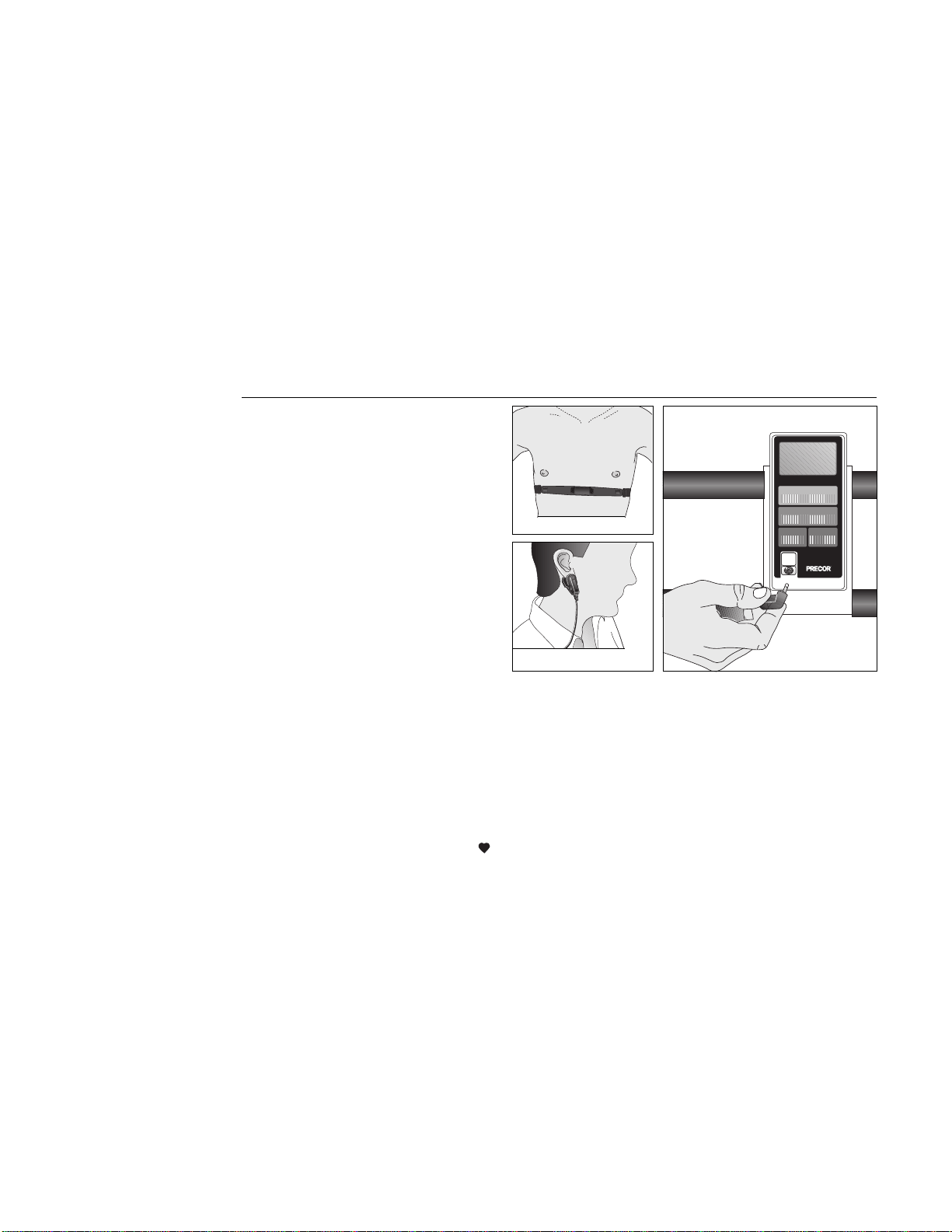
Using the Pulse Feature
With the Precor pulse feature, you can use the display to help maintain your
heart rate in its training zone. Diagram 24 on page 24 shows your target heart
rate or training zone. To receive the best possible cardiovascular fitness level,
you want to maintain your heart rate in your training zone while you workout .
You can use the pulse feature in one of two ways:
Diagram 21
Precor ear clip and Polar heart
rate options
•
Precor Ear Clip Option
. A pulse detector plugs into the electronic console.
Your pulse is detected once you attach the ear clip to your ear lobe.
•
Precor Heart Rate Option
. The receiver plugs into the electronic console.
When you wear the chest strap the console displays your heart rate.
To use the pulse feature, plug the pulse detector into the electronic console and
attach the ear clip to your ear lobe. See Diagram 21. Or, if you have a Precor/
Polar chest strap, put it on and plug the receiver into the electronic console.
Note: A
appears in the lower right corner of the display when you plug the
pulse detector in or attach the receiver and put on the Precor/Polar chest strap.
Follow the workout instructions on the following pages. Use the MODE key to
highlight SCAN mode or to select the PULSE display.
Important: Your heart rate will not appear if the pulse detector or chest strap
cannot transmit a heart beat. This can occur if you remove the ear clip (or chest
strap) or the ear clip (or chest strap) becomes dislodged. Occasionally, due to
medication, caffeine, or physiology of the heart (such as an irregular heart beat)
the receiver in the console cannot correctly detect a heart beat. Verify the
accuracy of the heart rate reading by taking your pulse one or twice during your
workout. For additional information, review the Owner’s Manual that accompa-
nied your Precor Heart Rate Option.
Precor Ear Clip Option Connection
Precor/Polar Chest Strap
Precor Ear Clip

Page 20
Pausing Your Workout
Since the climber has an automatic auto-pause feature, you can pause during
your workout to answer the telephone or take a short rest. To pause your
workout, simply stop stepping on the climber. Five minutes after you stop
exercising the electronics unique screen-saver feature turns off the display and
saves your position. When you resume your workout and step on to the climber,
the displays continue from the point you left off and provide an accurate readout
of your total workout time.
Note: When you pause, the internal clock causes the TIME display to continue
counting. If you return to your workout before 5 minutes elapse, the TIME
display reverts back to your actual workout time.
Ending a Workout
To end your workout, simply stop stepping. You can also press the START/
STOP key. In either case, the displays on the console freeze, allowing you to
review your workout statistics.
You can then do one of two things: either press RESET to return the displays to
zero or let them stand, which lets you track total exercise time and steps over
several exercise sessions. The electronics count TIME, TOTAL STEPS, and
TOTAL CALories cumulatively, so if you do not press RESET at the end of your
workout, the electronic console will continue counting from the point you left
off.
With the console’s unique screen-saver feature, you do not have to worry about
turning OFF the console when you finish your workout. Five minutes after you
stop exercising the screen-saver turns OFF the display.
How to Use the 718e Climber
This section explains how to work out on the climber safely and effectively.
When using the climber, follow these general guidelines:
• At the beginning of a workout, warm-up by taking several minutes to bring
your heart rate into your training zone (see Diagram 24 on page 24).
• After your workout, walk slowly for several minutes to cool down your
body and lower your pulse rate.
• Protect your knees by keeping them directly over your toes. Avoid taking
steps that are too big or bending your knees beyond 90 degrees.
• Keep your feet on the black footpads—moving your feet too far forward
might cause you to bump the cylinders with your knees.
• Keep your shoulders and back relaxed. Hold your head up—looking at your
feet or the floor strains your neck and back muscles. Avoid bouncing or
swinging your hips from side to side.
• Set the resistance at a low level initially until your muscles warm up and
your heart rate reaches its target zone. You can then increase the level to
the desired setting for working out.
• Gently stretch your lower body and back after a workout to help prevent
stiffness or soreness.
Working Out on the 718e Climber
To use the 718e climber, take the following steps:
1. Press RESET on the electronic console and hold for 3 seconds. Release the
key at the “beep” sound. Press MODE until the TIME function is highlighted
and the TIME display appears.
CAUTION: Before beginning
any fitness program, you
should have a complete
physical examination by your
physician.
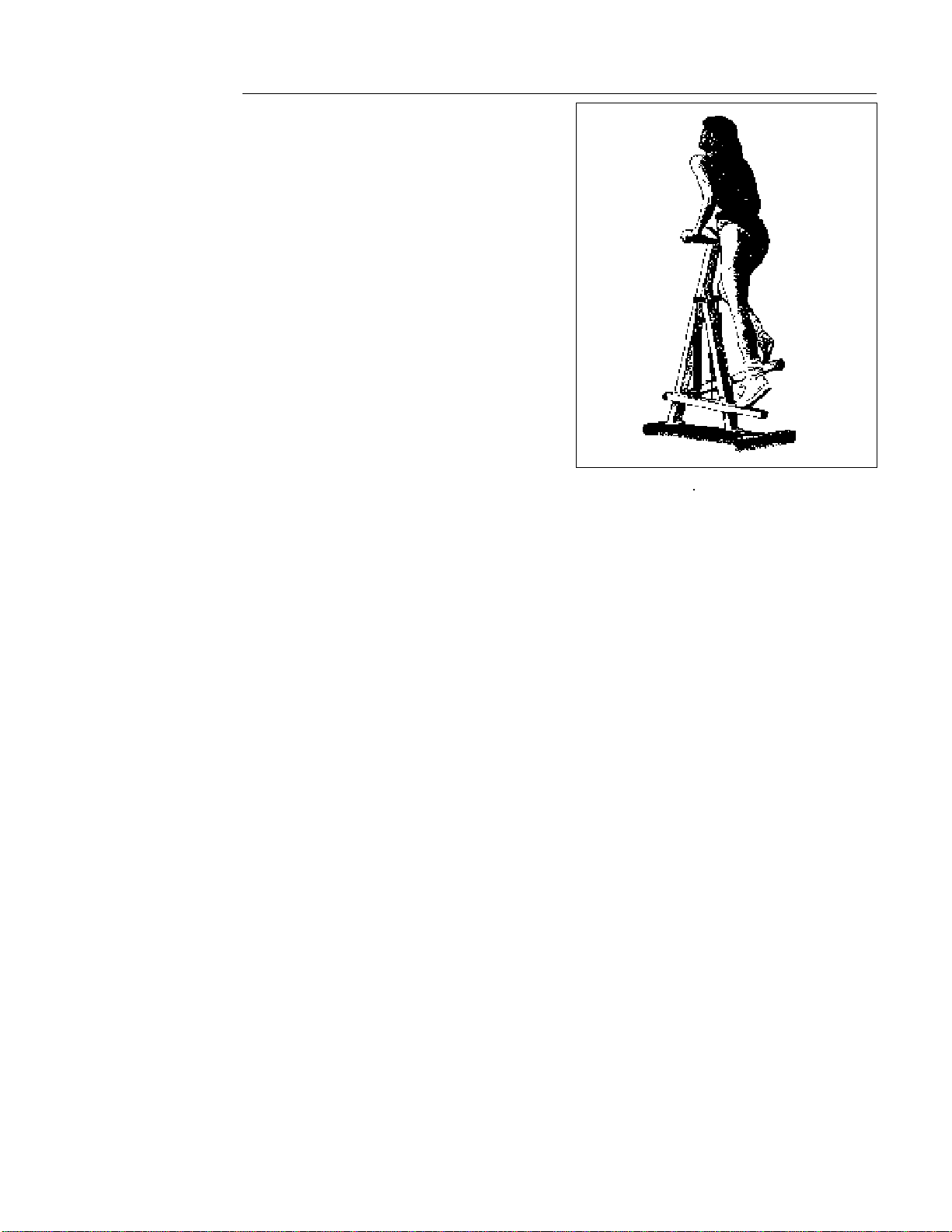
Page 21
Diagram 22
Working out on the 718e
2. After you have set the resistance level at a low setting and finished any
desired pre-workout stretching, step onto the climber. Make sure that your
weight is balanced and your hands and feet are positioned securely. Refer
to
How to Use the 718e Climber
.
3. Start your workout by taking steps 4 to 8 inches in height, at a cadence
that will allow your heart rate to reach your training zone within 5 minutes.
See Diagram 22. To get your heart rate into your training zone, you might
have to adjust the resistance setting.
Note: To increase your heart rate, increase the step speed by adjusting the
resistance cylinder to a lower setting. To slow your heart rate, slow the
step speed by moving to a higher setting.
4. After your warm-up period, maintain your heart rate in your training zone
during your aerobic session. As you work out, vary your body position to
reduce localized muscle fatigue and to exercise all your lower body
muscles. See
Sample Exercise Routines
.
5. When you are finished exercising, cool down for 3 to 5 minutes by
gradually reducing your step rate and height. If earlier you decreased
resistance for your aerobic session, move the resistance level to a higher
setting to help your body cool down. A proper cool-down helps to
transport excess lactic acid out of the working muscles, allowing them to
recover faster.
6. To end your workout, simply stop stepping. You can also press the START/
STOP key. In either case, the displays on the console freeze, allowing you
to review your workout statistics. Press RESET to return the displays to
zero or let them stand, which lets you track exercise time and steps over
several sessions. Five minutes after you stop exercising, the display
automatically turns OFF.
For best results, vary your workouts by changing duration, intensity, footstep,
body position and type of work (such as interval training). Keep track of your
workouts by writing them down so you can monitor your progress toward your
fitness goals and use the information to plan interesting and challenging
workouts.

Page 22
Sample Exercise Routines
For a good upper body workout, set the resistance cylinders at a moderate
level—between the markings 4 and 6 and take the following steps:
1. Stand erect with your feet placed firmly on the stair arm footpads.
2. To maintain your balance after stepping onto the stair arms, place your
hands in a comfortable position on top of the handrails, palms facing
down. You should have a slight bend at your elbows. Do not straighten
your arms out completely and do not place your weight on the handrails,
use the handrails for balance only.
3. As you transfer your weight and press down with one leg, the opposite leg
should rise to about a 90 degree angle. Do not raise your leg above a 90
degree angle as you can cause injury to yourself.
4. Become familiar with the movement of the stair arms. Transfer your weight
between stair arms in one fluid motion. Do not bounce, bob, or rock up
and down or back and forth. Keep your back straight and erect while you
work out.
When you first start out, try a one-minute rest and one-minute work interval.
During the rest interval, you should let your body relax, continuing to transfer
your weight from one stair arm to the other with your hands relaxed, yet
maintaining your balance holding onto the handrails. During the work interval,
concentrate on your movement, keeping your knees bent, pushing down and
lifting up, in one continuous motion.
Calf muscle workout—during your downward stroke, as the pedal tails away,
let your heel come off the foot pedal. This helps work your calf muscle group.
Gluteal and Hamstring workout—Bend your arms at the elbow and place them
along the upper length of the handrail. Bend your body at the hips while you rest
your arms on the handrails. Then, keep your back straight while you bring your
knees up toward your chest to begin working your gluteals and hamstrings.
Remember, do not bend your knees more than 90 degrees, as you can cause
injury to yourself.
Quadricep workout—Hold onto the handrails while you sit back, knees bent,
placing your weight directly over the footpads. You should be able to feel light
pressure on your quadriceps.
Do not position your weight so far back that the
front crossbar on the climber comes off the floor.
Keep your back straight, in an
upright position, as you take shorter, faster steps. Keep your knees bent
throughout your workout to isolate and work out your quadricep muscles.
CAUTION: Before beginning
any fitness program, you
should have a complete
physical examination by your
physician.
CAUTION: Throughout your
workout, periodically check
your heart rate. Never allow
your heart rate to exceed 80%
of your training zone. Refer to
Diagram 24 on page 24 to
determine the training zone
that is appropriate for your
age group.
CAUTION: Make sure that both
cylinders are set at the same
resistance to ensure a
smooth, balanced feel during
your workout.
Page 23
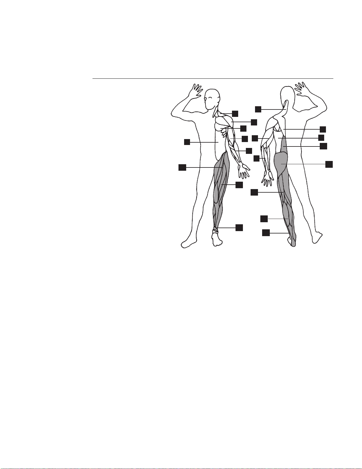
General Aerobic Training Information
A workout on the Precor 718e climber provides excellent and efficient cardio-
vascular conditioning, while strengthening and toning the thighs, calves, and
hips. The darkened areas in Diagram 23 indicate the muscles improved.
Diagram 23
Muscles exercised during a
stair climber workout.
1. Trapezius
2. Deltoid
3. Pectorals
4. Rhomboids
5. Triceps
6. Biceps
7. Latissimus Dorsi
8. Forearm Flexors/Extensors
9. Abdominals
10. Erector Spinae
11. Gluteals
12. Hip Flexors
13. Quadriceps
14. Hamstrings
15. Gastrocnemius/Soleus
16. Peroneus Longus/Brevis
To get the most out of each workout, a general understanding of the principles
behind aerobic training is invaluable. The best source of fitness information is
your specialty fitness dealer. In addition to providing information on which
exercise equipment is the best for your individual needs, your specialty fitness
dealer can provide useful advice on training, technique, and exercise physiology.
Your dealer can also recommend good books on these subjects.
To help you get started in planning and carrying out your fitness program, this
section provides some basic information on aerobic exercise—such as how
hard you should work out, how long each session should be, and how often you
need to exercise to benefit from a regular program.
9
16
6
12
2
1
4
3
16
1
8
5
8
13
14
15
11
10
7
Page 24
How Hard Should I Exercise?
Studies have shown that to achieve the benefits of aerobic exercise, it is
necessary to work out hard enough to raise your heart rate to a certain
minimum level, called the “training zone.” Your training zone depends on your
age and level of fitness.
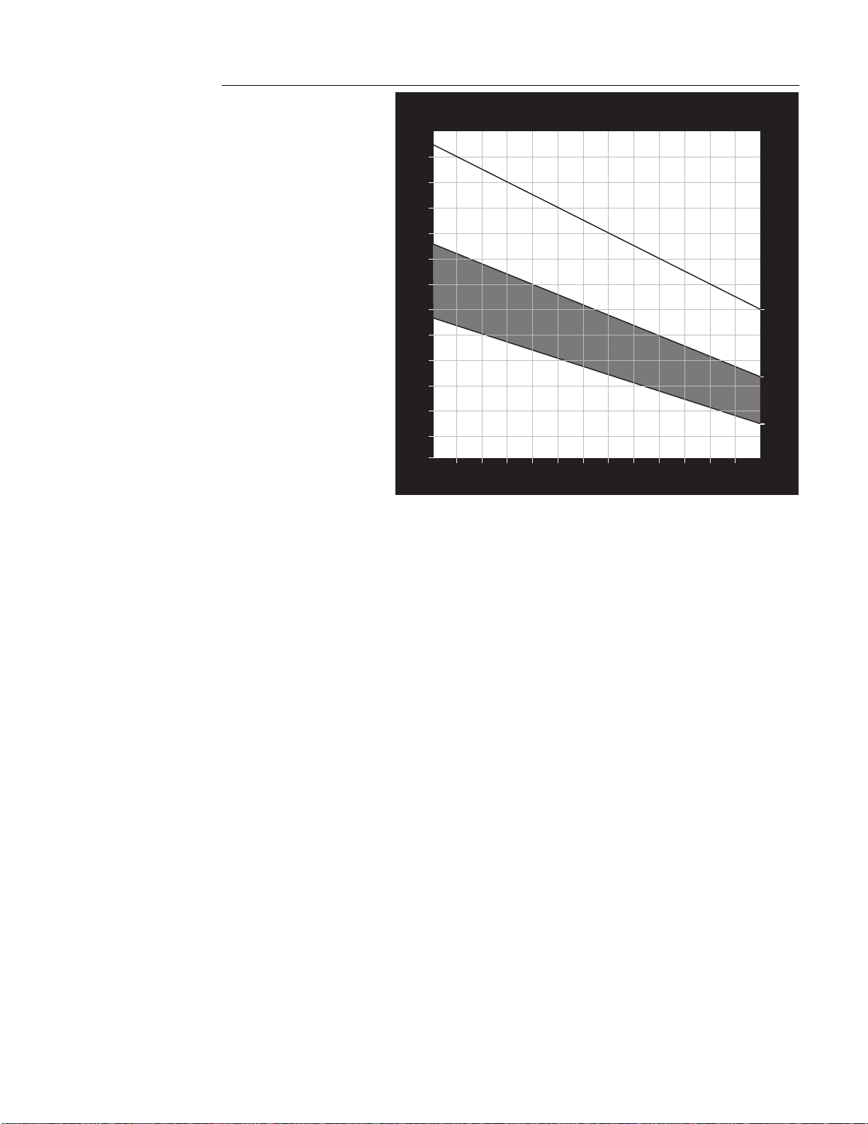
Diagram 24 shows your recommended heart rate training zone, which is
calculated using your age and your maximum attainable heart rate. The chart is
based on a resting heart rate of about 72 for males and 80 for females. Your
optimum training zone is between 65% and 80% of your maximum heart rate.
For efficient aerobic exercise, work only hard enough to keep your heart rate in
this zone. You will obtain the greatest fat-burning benefits when you exercise
within the optimum training zone.
Pushing yourself beyond the recommended range, (that is, exercising so hard
that your heart rate rises above 80% of maximum) can overstress your
muscles. To increase cardiovascular improvement, exercise
longer
, not harder.
Keep in mind that this zone is an approximation, to be used as a guideline—
individual heart rates vary according to several physiological factors. To
determine your training zone, find your age on the diagram, and then find the
area where the training zone and your age intersect. For example, if you are 35
years old, your training zone is between 114 and 140 beats per minute.
Remember this zone—this is the heart rate you should try to maintain as you
work out.
To determine your heart rate, take your pulse at a place that you can reach easily
and comfortably while you exercise. Typical places for measuring heart rate are
directly over the heart on the left side of the chest, on either side of the neck,
over the temple, or on the thumb side of either wrist. Wherever you measure
your pulse, make sure that you use your index and middle fingers—
not your
thumb
. Your thumb has a strong pulse, which can affect your heart rate reading.
Diagram 24
Heart rate training zones
HEART RATE TRAINING ZONE
70
80
90
100
110
120
130
140
150
160
170
180
190
20
25 30 35 40 45 50 55 60 65 70 75
YOUR AGE
YOUR HEART RATE
MAX.
HEART
RATE
80% OF
MAX.
HEART
RATE
65% OF
MAX.
HEART
RATE
124
120
114
110
107
104
101
98
91
152
148
140
136
132
128
124
120
116
112
180
175
170
165
160
155
150
145
140
135
RECOMMENDED TRAINING ZONE
88
117
144
108
94
185
190

Page 25
Once you locate your pulse, look at a watch or a clock with a second hand and
count the beats for six seconds. Multiply that number by 10 to determine the
total number of beats per minute. For example, if you count 14 beats over six
seconds, the total number of beats per minute is 140. Compare the total number
of beats with your training zone as identified in Diagram 24. If necessary,
increase or decrease your activity level to bring your heart rate into your training
zone. You can increase your activity level by increasing your resistance level and
stepping at a higher cadence. Similarly, lowering the resistance and decreasing
your steps per minute will lower your heart rate.
Remember—your heart rate is
the definitive measure of how hard you are working.
Regardless of your fitness level, avoid doing too much too soon. Setting the
resistance level too high, stepping too deeply (taking large steps), or stepping
too quickly for too long are common errors. Give yourself time to become
familiar with your climber and improve your fitness level. Then you can
gradually increase your resistance level and stepping cadence to make your
workouts more challenging.
How Long Should I Exercise?
The length of each exercise session depends on your fitness level. Exercise
physiologists have determined that, to attain cardiovascular benefits from
exercise, you should maintain your heart rate in the training zone for at least 15
minutes. This does not include warm-up and cool-down time. You should
always allow several minutes to bring your heart rate into the training zone, by
starting out slowly and gradually increasing the work level. Similarly, use
several minutes of light exercise after the workout to bring your heart rate down
to near resting level.
The higher your fitness level, the longer you should maintain your heart rate in
the training zone (between 20 and 30 minutes). Beginners should always start
slowly, and gradually increase their sessions to 20 minutes or more.
How Often Should I Exercise?
Research indicates that aerobic sessions of 20 minutes or more should be done
at least 3 to 5 times a week to obtain significant cardiovascular benefits. Most
experts agree that sensible eating habits and regular aerobic exercise are the
keys to weight control and fitness. A recent study, which tracked several
subjects over a period of years, conclusively shows that exercise, not dieting, is
the key factor to successful long-term weight loss.

Page 26
Maintenance and Troubleshooting
The 718e climber requires very little maintenance. The only maintenance you
need to do periodically is to clean the climber. You will also need to change the
batteries when they wear down. Instructions for these procedures are provided
in this section.
If you encounter problems with the climber, refer to
Troubleshooting Tips
in this
section for help.
Cleaning the Climber
Clean the 718e climber periodically with mild solution of soap and water or a
general household cleaner. Wipe the surface of the electronic console with a
moist sponge or cloth. Dry with a clean towel. Never pour liquids on the 718e
electronic console.
Changing the Batteries
The electronic console comes with two “AA” alkaline batteries installed. When
your console no longer shows a digital readout or the count becomes erratic,
you need to change the batteries.
Note: Occasionally, the batteries can become dislodged, so you need to
reposition the batteries in the drawer, but not necessarily replace them with new
batteries.
1. Find the drawer on the side of the electronic console and press in lightly to
open it.
2. Use your fingers to slide the drawer out and expose the battery case.
Remove the old batteries and replace them with two new “AA” alkaline
batteries. The displays light up and the console beeps.
Note: Align the batteries to the proper polarity (+ and - indicators are inside
the battery case).
3. Close the battery drawer by pushing it gently into the electronic console.
4. Press START/STOP to activate the timer (TIME display).
Note: Press RESET to “reset” the displays to zero.
CAUTION: Abrasive cleaners
or polishes will damage the
surface finish.

Page 27
718e
Troubleshooting Tips
Check the chart below to see if your problem is listed. If the following informa-
tion does not solve a particular problem, call your authorized Precor dealer. See
Obtaining Service
in this section for information
Problem Solution
Electronics, no display • Replace batteries. See instructions on the
previous page.
• Clean battery connections.
Electronics, no stroke count • Reed switch to magnet spacing is incorrect.
Electronic unit shuts down after 5 minutes—
see step 10 in the
Assembly Instructions
.
• Magnet placement incorrect.
• Pinched or severed cable.
Frame loose • Recheck and tighten frame and base bolts.
Squeaks • Lubricate the rope pulley mechanism.
• Lubricate resistance cylinder connectors.
• Check bolts for tightness.
Obtaining Service
Do not attempt to service the 718e climber yourself except for changing the
batteries or performing other maintenance tasks as described in this manual.
For further information about product operation or service, contact an autho-
rized Precor dealer (or a Precor Factory Authorized Service Company). To locate
the Precor dealer nearest you, call 1-800-4-PRECOR.
To help the customer service representative expedite your call, have your serial
number readily available. Use the model and serial numbers whenever you call
your Precor dealer or the customer service representative. The serial number on
the 718e climber is located on the underside of the base.
Model number: ________ Serial number: ___________________________

Page 28
Precor is a registered trademark of Precor Incorporated.
© 1988 Precor Incorporated, Rd. 1989.
Specifications subject to change without notice.
1-800-4-PRECOR
NOTICE:
Precor is widely recognized for its innovative, award winning designs of exercise equipment. Precor
aggressively seeks U.S. and foreign patents for both the mechanical construction and the visual aspects of
its product design. Any party contemplating the use of Precor's product designs is hereby forewarned that
Precor considers the unauthorized appropriation of its proprietary rights to be a very serious matter. Precor
will vigorously pursue all unauthorized appropriation including through legal actions.
Precor Incorporated
P.O. Box 3004
Bothell, WA USA 98041-3004
P/N 31295-112
6/95
USA
R