DIGITAL LOGIC 7
VID 1
DVD
CD
FMAM
TAPE
6 8 CH
VID 2
VID 3
VID 4
PRO LOGIC
3 STEREO DSP
5 7 CH. STEREO
SURR. OFF
AVR 240
Optical 3
Coaxial 3
Video 4
AVR 240
AUDIO/VIDEO RECEIVER
OWNER’S MANUAL
Power for the Digital Revolution
.
®
®
AVR 240 AUDIO/VIDEO RECEIVER
3 Introduction
4 Important Safety Information
4 Unpacking
5 Front-Panel Controls
8 Rear-Panel Connections
11 Remote Control Functions
15 Installation and Connections
1
7
S
ystem Configuration
1
7
S
peaker Selection and Placement
19 System Setup
19 Using the On-Screen Display
20 Input Setup
21 Surround Setup
23 Automated Speaker Setup Using EzSet+
25 Manual Setup
26 Speaker Setup
28 Delay Settings
29 Output Level Adjustment
31 Operation
31 Basic Operation
31 Source Selection
31 6-Channel/8-Channel Direct Input
31 Volume Control
32 Surround Mode Selection
32 Digital Audio Playback
33 Surround Mode Chart
37 Tuner Operation
37 Recording
37 Using
38 Output Level Trim Adjustment
39 Advanced Features
41 Programming the Remote
41 Programming Device Codes
41 Macro Programming
42 Programmed Device Functions
43 Volume Punch-Through
43 Channel Control Punch-Through
43 Transport Control Punch-Through
43 Resetting the Remote Memory
44 Function List
46 Setup Code Tables
56 Troubleshooting Guide
56 Processor Reset
57 T
echnical Specifications
57 T
rademark Acknowledgements
58 Index
59 Appendix – Settings Worksheet
The
Bridge
TM
2 TABLE OF CONTENTS
T
ypographical Conventions
In order to help you use this manual with the remote control,
front-panel controls and rear
-panel connections,
certain conventions have been used.
EXAMPLE – (bold type) indicates a specific remote control or front-panel button, or rear
-panel
connection jack
EXAMPLE – (OCR type) indicates a message that is visible on-screen or on the front-panel
information display
1 – (number in a square) indicates a specific front-panel control
¡ – (number in a circle) indicates a rear-panel connection
a – (number in an oval) indicates a button or indicator on the remote
The appearance of the text or cursor for your receiver’s on-screen menus may vary slightly from the
illustrations in this manual.
Whether the text appears in all uppercase or upper
- and lowercase characters
,
performance and operation remain the same.
F
or Canadian model
Modèle pour les Canadien
Cet appareil numérique de la classe B est conforme
à la norme NMB-003 du Canada.
Sur les modèles dont la fiche est polarisee:
ATTENTION: Pour éviter les chocs électriques, introduire
la lame la plus large de la fiche dans la borne
correspondante de la prise et pousser jusqu’au fond.
T
his class B digital apparatus complies with Canadian
ICES-003.
F
or models having a power cord with a polarized plug:
CAUTION: To prevent electric shock, match wide blade
of plug to wide slot, fully insert.
Please register your product on our Web site at
www.harmankardon.com. Note: You’ll need the
product’s serial number. At the same time you can
choose to be notified about our new products and/or
special promotions
.

INTRODUCTION
T
hank you for choosing Harman Kardon
®
! W
ith
t
he purchase of a Harman Kardon AVR 240, you are
about to begin many years of listening enjoyment.
Designed to provide all the excitement and detail of
movie soundtracks and
every nuance of musical selec-
t
ions, the AVR 240
a
ccomplishes its mission by har-
nessing advanced technologies usually found only in
higher-priced receivers.
The AVR 240 has been engineered so that it is easy
to take advantage of all the power of its digital tech-
nology. However, to obtain the maximum enjoyment
from your new receiver, we urge you to read this
manual. A few minutes spent learning the functions of
the various controls will enable you to take advantage
of all the power the AVR 240 is able to deliver.
If you have any questions about this product,
its instal-
lation or its operation, please contact your retailer or
custom installer. They are your best local sources of
information.
Description and Features
The AVR 240 is versatile and multifeatured, incorpo-
rating a wide range of listening options. In addition to
Dolby
* Digital and DTS
®
decoding for digital sources,
a broad choice of Matrix surround-encoded or stereo
surround modes are available for use with your CD,
VCR, TV broadcasts and the AVR 240’s own FM/AM
tuner. Along with Dolby Digital EX, Dolby Pro Logic* IIx,
DTS Neo:6
®
, DTS 96/24, Dolby 3 Stereo, and Hall
and Theater modes, the AVR 240 offers Harman
International’s exclusive Logic 7
®
processing in both
5.1 and 7.1 versions to create a wider, more enveloping
field environment and more defined fly-overs and pans.
Another exclusive is VMAx
®
, which uses proprietary
processing to create an open, spacious sound field
even when only two front speakers are available. Dolby
Virtual Speaker is also available to create an envelop
-
ing sound field when fewer than six speakers are
used. The latest Dolby Headphone modes provide a
much more open and realistic presentation for private
headphones listening.
In addition to providing a wide range of listening
options, the AVR 240 is easy to configure so that it
provides the best results with your speakers and spe-
cific listening-room environment. On-screen menus
combine with the EzSet+ system to automate speaker
configuration and overall setup, resulting in a perfectly
balanced sound field presentation that accurately
reproduces the artist’s intent.
F
or the ultimate in flexibility, the AVR 240 features
c
onnections for five video devices, all with both com-
posite and S-video inputs. Two additional audio inputs
are available, and six digital inputs make the AVR 240
capable of handling all the latest digital audio sources.
F
or compatibility with the latest HDTV video sources
and progressive scan DVD players, the AVR 240 also
features assignable two-input, wide-bandwidth, low-
crosstalk component video switching.
The front panel offers coax and optical digital inputs
for direct connection to digital recorders. Two video
recording outputs, a preamp-out and a color-coded
eight-channel input make the AVR 240 virtually future-
proof, with everything needed to accommodate tomor-
row’s new formats right onboard.
Until now
, Harman Kardon AVRs have been able to
accommodate almost any source device equipped
with line-level analog, optical digital or coaxial digital
outputs, including most digital media players. With one
simple connection between the AVR 240 and the
optional Harman Kardon , you are able to
listen to materials stored on your compatible Apple
®
iPod
®
** (not included). Your AVR’s system remote con-
trol has been preprogrammed with control codes that
enable you to select tracks for playback and navigate
many of your iPod’s functions, even from across the
room. The Bridge
™
will even let you charge your iPod.
The AVR 240’s powerful amplifier uses traditional
Harman Kardon high-current design technologies
to meet the wide dynamic range of any program
selection.
Harman Kardon invented the high-fidelity receiver
more than fifty years ago. With
state-of-the-art circuitry
and time-honored circuit designs
, the AVR 240 is the
perfect combina
tion of the latest in digital audio tech-
nology
,
a
quiet yet powerful analog amplifier in an
ele
-
gant,
easy-to-use package.
n A
wide range of digital and matrix surround
m
odes, including Dolby
®
D
igital, Dolby Digital EX
,
Dolby Pro Logic
®
IIx, Dolby Virtual Speaker, Dolby
Headphone, DTS
®
, DTS-ES
®
Discrete and Matrix,
DTS 96/24
®
and DTS Neo:6
®
n Seven channels of high-current amplification
n
Harman Kardon’s exclusive Logic 7
®
processing
,
available with both 7.1 and 5.1 processing in
a
variety of modes, and two modes of VMAx
®
n system with included microphone
automatically configures speakers and sets
delay times and output levels for optimal
sound presentation
n Programmable remote delivers complete con-
trol over AVR and seven additional source
components
n High-bandwidth, HDTV-compatible component
video switching with assignable inputs
n Discrete front-panel coaxial and optical digital
inputs for easy connection to portable digital
devices and video game consoles
n Connects to Harman Kardon’s
(optional) for charging, playback and control
of a compatible iPod
®
device (not included)
n Input titling for all input sources (except tuner)
n Extensive bass management options, includ-
ing four separate crossover groupings
n On-screen menu and display system with
choice of blue or black background screen
The
Bridge
T
M
T
M
TM
TM
The
Bridge
TM
INTRODUCTION 3
**
Compatible with all iP
od models equipped with a dock connector, including third-generation “Click Wheel” models and newer. Not compatible with iPod shuffle models.
Although iPod photo models are compatible, images stored on the iPod may not be viewed.

SAFETY INFORMATION
Important Safety Information
Verify Line Voltage Before Use
Your AVR 240 has been designed for use with
120-volt AC current. Connection to a line voltage
other than that for which it is intended can create a
s
afety and fire hazard and may damage the unit.
If you have any questions about the voltage requirements
for your specific model, or about the line voltage in your
a
rea, contact your selling dealer before plugging the unit
into a wall outlet.
Do Not Use Extension Cords
To avoid safety hazards, use only the power cord
attached to your unit. We do not recommend that
extension cords be used with this product. As with all
electrical devices, do not run power cords under rugs
or carpets or place heavy objects on them. Damaged
power cords should be replaced immediately by an
authorized service center with a cord meeting factory
specifications.
Handle the AC Power Cord Gently
When disconnecting the power cord from an AC out-
let, always pull the plug; never pull the cord. If you do
not intend to use the unit for any considerable length
of time, disconnect the plug from the AC outlet.
Do Not Open the Cabinet
There are no user-serviceable components inside this
product. Opening the cabinet may present a shock
hazard, and any modification to the product will void
your guarantee. If water or any metal object such as a
paper clip, wire or a staple accidentally falls inside the
unit, disconnect it from the AC power source immedi-
ately, and consult an authorized service center.
CATV or Antenna Grounding
If an outside antenna or cable system is connected to
this product, be certain that it is grounded so as to pro-
vide some protection against voltage surges and static
charges. Section 810 of the National Electrical Code,
ANSI/NFPA No. 70-1984, provides information with
respect to proper grounding of the mast and supporting
structure, grounding of the lead-in wire to an antenna
discharge unit, size of grounding conductors, location
of antenna discharge unit,
connection to grounding
electrodes and requirements of the grounding
electrode.
NOTE
TO CA
TV SYSTEM INSTALLER:
This reminder
is provided to call the CATV (Cable TV) system
installer’s attention to article 820-40 of the NEC that
provides guidelines for proper grounding and, in par-
ticular, specifies that the cable ground shall be con-
nected to the grounding system of the building, as
close to the point of cable entr
y as possible
.
I
nstallation Location
n T
o ensure proper operation and to avoid the poten-
tial for safety hazards, place the unit on a firm and
level surface. When placing the unit on a shelf, be
certain that the shelf and any mounting hardware
c
an support the weight of the product.
n Make certain that proper space is provided both
above and below the unit for ventilation. If this
product will be installed in a cabinet or other
enclosed area, make certain that there is sufficient
air movement within the cabinet. Under some
circumstances a fan may be required.
n Do not place the unit directly on a carpeted
surface.
n Avoid installation in extremely hot or cold locations,
or in an area that is exposed to direct sunlight or
heating equipment.
n Avoid moist or humid locations.
n Do not obstruct the ventilation slots on the top of
the unit, or place objects directly over them.
n Due to the weight of the AVR 240 and the heat
generated by the amplifiers, there is the remote
possibility that the rubber padding on the bottom
of the unit’s feet may leave marks on certain
wood or veneer materials. Use caution when
placing the unit on soft woods or other materials
that may be damaged by heat or heavy objects.
Some surface finishes may be particularly sensitive
to absorbing such marks due to a variety of factors
beyond Harman Kardon’s control, including the
nature of the finish, cleaning materials used, and
normal heat and vibration caused by the use of the
product, or other factors. We recommend that cau-
tion be exercised in choosing an installation loca-
tion for the component and in normal maintenance
practices, as your warranty will not cover this type
of damage to furniture
.
Cleaning
When the unit gets dirty, wipe it with a clean, soft, dry
cloth. If necessary, and only after unplugging the AC
power cord,
wipe it with a soft cloth dampened with
mild soapy water, then a fresh cloth with clean water.
Wipe dry immediately with a dry cloth. NEVER use
benzene, aerosol cleaners, thinner, alcohol or any other
volatile cleaning agent. Do not use abrasive cleaners,
as they may damage the finish of metal parts
.
Avoid
spraying insecticide near the unit.
Moving the Unit
Before moving the unit,
be certain to disconnect any
interconnection cords with other components
,
and
make certain that you disconnect the unit from the
AC outlet.
Important Information for the User
This equipment has been tested and found to comply
w
ith the limits for a Class-B digital device, pursuant to
P
art 15 of the FCC Rules. The limits are designed to
provide reasonable protection against harmful interfer-
ence in a residential installation. This equipment gener-
ates,
uses and can radiate radio-frequency energy
and,
i
f not installed and used in accordance with the
instructions, may cause harmful interference to radio
communication. However, there is no guarantee that
harmful interference will not occur in a particular instal-
l
ation. If this equipment does cause harmful interfer-
e
nce to radio or television reception, which can be
determined by turning the equipment off and on, the
user is encouraged to try to correct the interference by
one or more of the following measures:
n Reorient or relocate the receiving antenna.
n Increase the separation between the equipment
and receiver.
n Connect the equipment into an outlet on a circuit
different from that to which the receiver is connected.
n Consult the dealer or an experienced radio/TV
technician for help.
This device complies with Part 15 of the FCC Rules.
Operation is subject to the following two conditions:
(1) this device may not cause harmful interference,
and (2) this device must accept interference received,
including interference that may cause undesired
operation.
NOTE: Changes or modifications may cause this
unit to fail to comply with Part 15 of the FCC Rules
and may void the user’s authority to operate the
equipment.
Unpacking
The carton and shipping materials used to protect your
new receiver during shipment were specially designed
to cushion it from shock and vibration. We suggest
that you save the carton and packing materials for
use in shipping if you move
, or should the unit ever
need repair.
To minimize the size of the carton in storage, you may
wish to flatten it. This is done by carefully slitting the
tape seams on the bottom and collapsing the carton.
Other cardboard inserts may be stored in the same
manner. Packing materials that cannot be collapsed
should be saved along with the carton in a plastic bag.
If you do not wish to save the packaging materials,
please note that the carton and other sections of the
shipping protection are recyclable.
Please respect the
environment and discard those materials at a local
recycling center.
It is important that you remove the protective plastic
film from the front-panel lens. Leaving the film in place
will affect the perfor
mance of your remote control.
4 SAFETY INFORMATION4 SAFETY INFORMATION
FRONT-PANEL CONTROLS
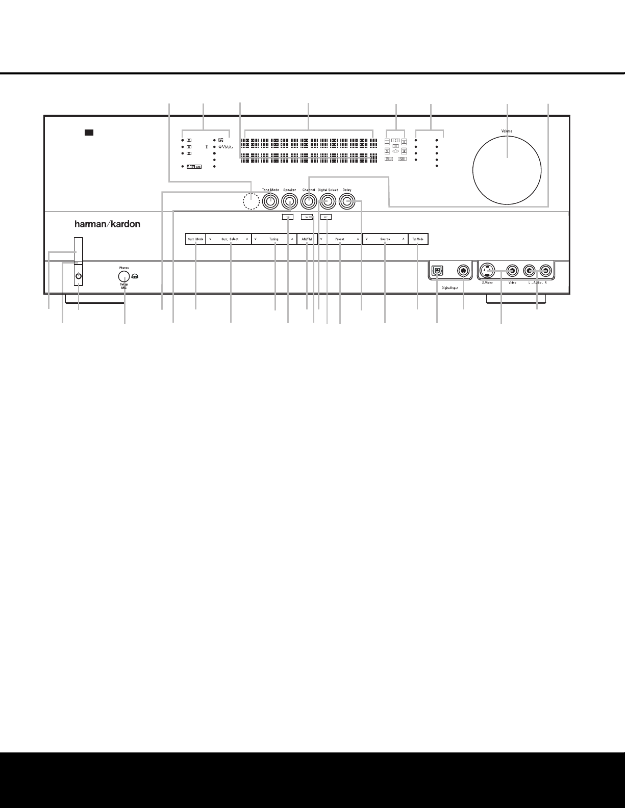
1 Main Power Switch: Press this button to apply
power to the AVR 240. When the switch is pressed
in, the unit is in a Standby mode, as indicated by the
amber
P
o
wer Indicator
2.
This button MUST be
pressed in to operate the unit. To turn the unit off and
prevent the use of the remote control, this switch
should be pressed until it pops out from the front
panel and the word
“OFF” is seen at the top of the
switch.
NOTE: This switch is normally left in the “ON” position.
2 Power Indicator: This LED lights amber when the
unit is in the Standby mode to signal that the AVR is
ready to be tur
ned on. When the unit is in operation,
the indicator is blue.
3 Standby/On Switch: When the Main Power
Switch
1
is
“ON,” press this button to turn on the
AVR 240; press it again to turn the unit off. The
Power
Indicator
2
turns blue when the unit is on.
4 Headphone Jack: This jack may be used to listen
to the AVR 240’s output through a pair of headphones.
The speakers will automatically be turned off when the
headphone jack is in use
.
When configuring your sys-
tem using EzSet+, the calibration microphone should
be plugged into this jack using the supplied adaptor
that converts the small mini-plug at the end of the
microphone’
s cord to a 1/4" plug.
5 T
one Mode:
This button controls the tone mode
settings, enabling adjustment of the bass and treble
boost/cut.
Y
ou may also use it to take the tone con-
trols out of the signal path completely for “flat”
response. The first press of the button displays a
TONE IN message in the Lower Display Line
ı and in the on-screen display
.
T
o take the controls
out of the signal path, press either of the
‹
‹
/
›
›
Buttons ) until the display reads TONE OUT.
T
o change the bass or treble settings
,
make sure that
TONE IN appears in the Lower Display Line ı
or press either of the
‹
‹
/
›
›
Buttons ) until it does.
Press the Tone Mode Button 5 until the desired
option of
TREBLE MODE or BASS MODE
appears in the Lower Display Line ı and in the
on-screen display and then press either of the
‹
‹
/
›
›
Buttons ) to enter the desired boost or cut setting.
Both treble and bass contours may be boosted or
cut by up to + or –10dB in increments of 2dB. See
pages 21 and 31 for more infor
mation on the tone
controls.
NOTE: The AVR 240 is not equipped with a traditional
Balance control. When listening to two-channel materi-
als, if you wish to adjust the stereo image, you may
use the
Channel
Adjust Selector
to increase or
decrease the level of the left front channel by up to +
or –10dB, and then to decrease or increase the right
front channel by the corresponding amount.
However
,
when listening to surround materials and most two-
channel materials
,
it is recommended that you leave
these settings at the results obtained during the config-
uration process described on pages 19 through 30.
1 Main Power Switch
2 Power Indicator
3 Standby/On Switch
4 Headphone Jack
5 Tone Mode
6 Speaker Selector
7 Surround Mode Group Selector
8 Surround Mode Selector
9 Tuning Selector
)
‹/›
Buttons
! Tuner Band Selector
@ Set Button
# Digital Input Selector
$ Preset Station Selector
% Delay Adjust Selector
^ Input Source Selector
& Tuner Mode Selector
* Optical 3 Digital Audio Input
( Coaxial 3 Digital Audio Input
Ó Video 4 Video Input Jacks
Ô Video 4 Audio Input Jacks
Channel Adjust Selector
Ò Volume Control
Ú Input Indicators
Û Speaker/Channel Input Indicators
Ù Upper Display Line
ı Lower Display Line
ˆ Surround Mode Indicators
˜ Remote Sensor Window
DIGITAL LOGIC 7
VID 1
DVD
CD
FMAM
TAPE
6 8 CH
VID 2
VID 3
VID 4
PRO LOGIC
3 STEREO DSP
5 7 CH. STEREO
SURR. OFF
1
2
6
7
#
Ú
(
*
Û
8
)
!
@
)
&
%
3
4
˜
5
9
$
^
Ò
Ó
AVR 240
ˆ
Ù
Ô
ı
Optical 3
Coaxial 3
V
ideo 4
FRONT-PANEL CONTROLS
FRONT-PANEL CONTROLS 55
NOTE: To make it easier to follow the instructions that refer to this illustration, a larger copy may be downloaded from the Product Support section for this product
at www.harmankardon.com.

6 Speaker Selector: Press this button to begin
t
he process of configuring the unit to match the type
of speakers used in your listening room. (See pages
26–28 for more information on speaker setup and
configuration.)
7 Surround Mode Group Selector: Press this but-
ton to select the top-level group of surround modes.
Each press of the button will select the current or last
u
sed mode in each of the surround mode groups
(e.g., Dolby, DTS, DTS Neo:6, Logic 7, DSP, Stereo).
When the button is pressed so that the name of the
surround mode group appears in the on-screen dis-
play and in the
Lower Display Line ı, press the
Surround Mode Selector 8 to cycle through the
individual modes available. For example, press this
button to select Dolby modes, and then press the
Surround Mode Selector 8 to choose from the
various Dolby mode options.
8 Surround Mode Selector: Press this button
to select from among the available surround mode
options for the mode group selected. The specific
modes will vary based on the number of speakers
available, the mode group and if the input source is
digital or analog. For example, press the
Surround
Mode Group Selector
7 to select a main mode
grouping such as Dolby or Logic 7, and then press
this button to see the specific mode choices available.
Note that the digital surround modes, such as Dolby
Digital and DTS, may not be accessed unless that type
of source signal is present, such as when a DVD movie
or television signal programmed in Dolby Digital or DTS
surround sound is playing. For more information on sur-
round mode selection, see pages 23 and 32.
9 Tuning Selector: Press the left side of the button
to tune lower-frequency stations and the right side of
the button to tune higher-frequen
cy stations
.
When the
tuner is in the Manual mode, each tap will increase or
decrease the frequency by one increment. When the
tuner receives a strong enough signal for adequate
reception,
MANUAL TUNED will appear in the
on-screen display and the
Lo
wer Display Line
ı.
When the tuner is the Auto mode, press the button
once, and the tuner will scan for a station with accept-
able signal strength.
When the next station with a
strong signal is tuned the scan will stop and the
on-screen display and
Lower Display Line ı
will indicate AUTO
TUNED
.
When an FM
Stereo station is tuned, the display will read
AUTO
ST
TUNED
.
To switch back and forth between the Auto and
Manual tuning modes
,
press the
T
uner Mode
Selector
&.
) ‹/› Buttons: When configuring the AVR 240’s
s
ettings, use these buttons to select from the available
choices
.
! Tuner Band Selector: Press this button to turn
t
he AVR on and to select the Tuner as the input. Press
it again to switch between the AM and FM frequency
bands. (See page 37 for more information on the tuner.)
@ Set Button: When making choices during the
setup and configuration process, press this button
to enter the desired setting into the AVR 240’s memory.
# Digital Input Selector: Press this button to
select one of the digital audio inputs or the analog
audio input for any source. (See pages 32–37 for
more information on digital audio.)
$ Preset Stations Selector: Press this button to
scroll up or down through the list of stations that have
been entered into the preset memory. (See page 37
for more information on tuner presets.)
% Delay Adjust Selector: Press this button to
begin the steps required to enter delay settings. (See
pages 28–29 for more information on delay times.)
^ Input Source Selector: Press this button to
change the input by scrolling up or down through the
list of
Input Indicators Ú.
& Tuner Mode Selector: Press this button to select
Auto or Manual tuning. When the button is pressed so
that the
AUTO appears in the Lower Display Line
ı, the tuner will search for the next station with an
acceptable signal when the
Tuning Selector 9u
is pressed. When the button is pressed so that
MANUAL appears in the Lower Display Line ı,
each press of the
Tuning Selector 9u will
increase the frequency
. This button may also be used to
switch between Stereo and Mono modes for FM radio
reception. When weak reception is encountered, press
the button so that
MANUAL appears in the Lower
Display Line
ı and on the on-screen display to
switch to Mono reception.
Press it again to switch back
to Stereo mode.
(See page 37 for more information on
using the tuner.)
* Optical 3 Digital
Audio Input:
Connect the optical
digital audio output of an audio or video product to this
jack. When the input is not in use, the built-in shutter will
close to avoid dust contamination that might degrade
future performance.
( Coaxial 3
Digital Audio Input:
This jack is used
for connection to the output of portable audio devices,
video game consoles or other products that have a
coax digital audio jack.
Ó Video 4 Video Input Jacks: These jacks may
b
e used for temporary connection to the composite or
S-video output of video games, camcorders or other
portable video products. You may make a connection
to either jack at any time, but not to both simultaneously.
Ô Video 4 Audio Input Jacks: These audio jacks
may be used for temporary connection to video
games or portable audio/video products such as
c
amcorders and portable audio players.
Channel Adjust Selector: Press this button to
begin the process of trimming the channel output lev-
els using an external audio source. (For more informa-
tion on output level trim adjustment, see page 38.)
Ò Volume Control: Turn this knob clockwise to
increase the volume, counterclockwise to decrease
the volume. If the AVR 240 is muted, adjusting the
Volume Control Òb will automatically release
the unit from the silenced condition.
Ú Input Indicators: The current selected source
will appear as one of these indicators. When the unit
is turned on, the entire list of available modes will
light briefly, and then revert to normal operation with
only the active mode indicator illuminated.
NOTE: When /DMP has been selected as
the input source, no
Input Indicator N will light.
DMP/THE BRIDGE IS CONNECTED
will scroll across the Upper Display Line P, unless
you have retitled the source name, in which case that
name will appear. See page 20 for more information
on input titling.
Û Speaker/Channel Input Indica
tors:
These indi
-
cators are multipurpose, indicating both the speaker
type selected for each channel and the incoming data-
signal configuration. The left, center, right, right surround
and left surround speaker indicators are composed of
three boxes
, while the subwoofer is a single box. The
center box lights when a “small” speaker is selected,
and the two outer boxes light when
“large”
speakers are
selected. When none of the boxes are lit for the center,
surround or subwoofer channels, no speaker has been
assigned that position. (See pages 26–28 for more
information on configuring speakers
.)
The letters inside each box display the active input
channels. For standard analog sources, only the L and R
will light,
indicating a stereo input. For a digital source,
the indicators will light to display the channels being
received at the digital input.
When the letters flash,
the
digital input has been interrupted. (See page 36 for
more infor
mation on the Channel Indicators
.)
Ù Upper Display Line: Depending on the unit’s sta-
tus
,
a variety of messages will appear here
.
In nor
mal
The
Bridge
TM
FRONT-PANEL CONTROLS
6 FRONT-PANEL CONTROLS
FRONT-PANEL CONTROLS

o
peration, this line will show current input source and
w
hich analog or digital input is in use. When the tuner is
the input, this line will identify the station as AM or FM
and show the frequency and preset number, if any.
ı Lower Display Line: Depending on the unit’s sta-
tus, a variety of messages will appear here. In normal
operation, the current surround mode will show here.
ˆ Surround Mode Indicators: The current selected
surround mode will appear as one of these indicators.
Note that when the unit is turned on, the entire list of
available modes will light briefly, and then revert to
normal operation with only the active mode indicator
illuminated.
NOTE: When the Dolby Virtual Speaker or Dolby
Headphone modes are in use
, no
Surround Mode
Indicator
R will light. However, the surround mode
name will scroll in the
Lower Display Line Q.
˜ Remote Sensor Window: The sensor behind
this window receives infrared signals from the remote
control. Aim the remote at this area and do not block
or cover it.
FRONT-PANEL CONTROLS
7
7
FRONT-PANEL CONTROLS
The Bridge
•
∞
¶
⁄
fi
ª
¡
£
‹
°
b
d
g
j
i
a
™
¢
§
‚
¤
›
‡
c
e
f
h
k
U
V
W
X
a
b
c
Z
Y
fl
·
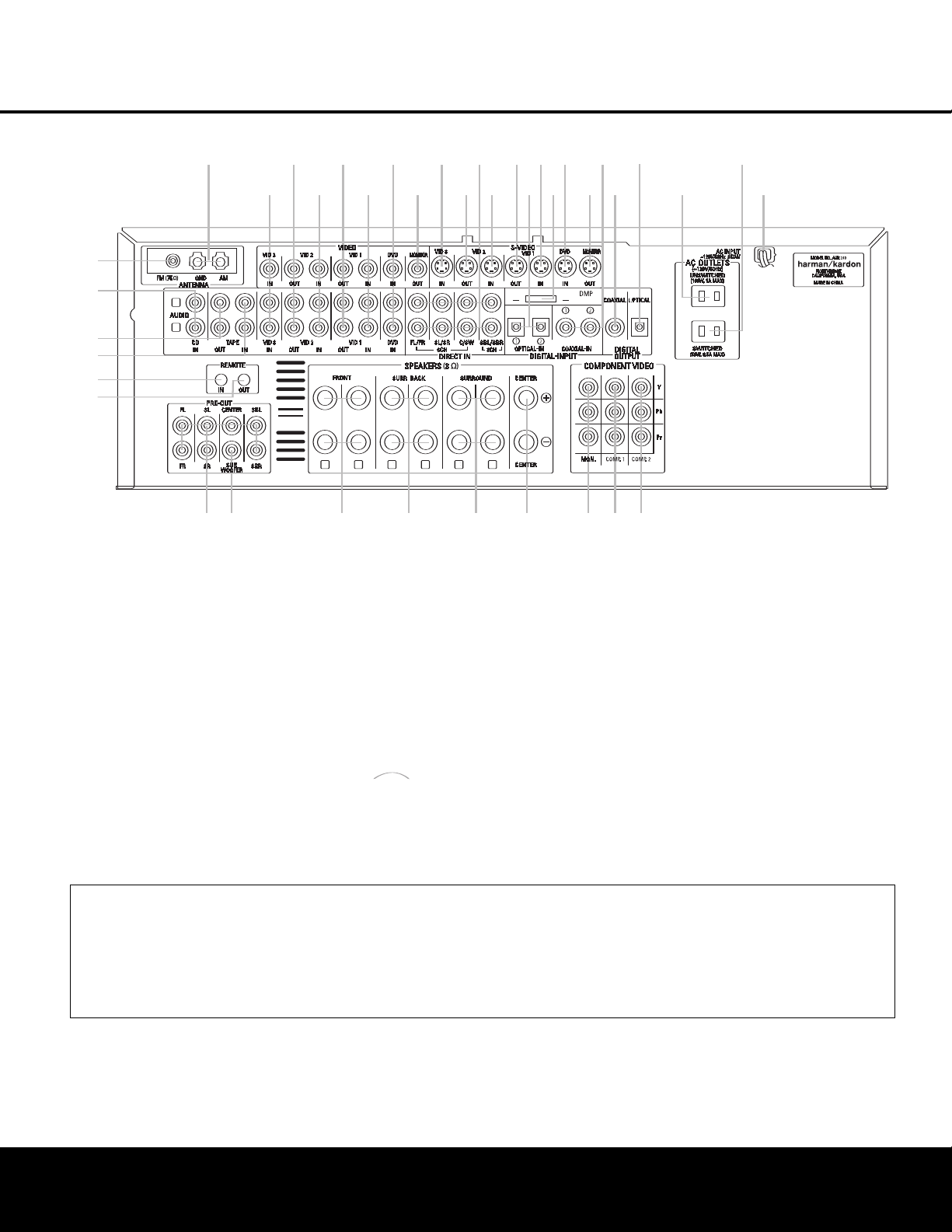
¡ FM Antenna Jack
™ CD Audio Inputs
£ Tape Outputs
¢ Tape Inputs
∞ Remote IR Input
§ Remote IR Output
¶ Preamp Outputs
• Subwoofer Output
ª Front Speaker Outputs
‚ Surround Back Speaker Outputs
⁄ Surround Speaker Outputs
¤ Center Speaker Outputs
‹ Component Video Monitor Outputs
› Component Video 1 Inputs
fi Component Video 2 Inputs
fl AC Power Cord
‡ Switched AC Accessory Outlet
° Unswitched AC Accessory Outlet
· Optical Digital Audio Output
a Coaxial Digital Audio Output
b Coaxial Digital Audio Inputs
c S-Video Monitor Output
d DVD S-Video Input
e DMP Connector
f Video 1 S-Video Input
g Optical Digital Audio Inputs
h Video 1 S-Video Output
i Video 2 S-Video Input
j 6/8-Channel Direct Inputs
k Video 2 S-Video Output
U Video 3 S-Video Input
V Video Monitor Output
W DVD Audio/Video Inputs
X Video 1 Audio/Video Inputs
Y Video 1 Audio/Video Outputs
Z Video 2 Audio/Video Inputs
a Video 2 Audio/Video Outputs
b Video 3 Audio/Video Inputs
c AM Antenna Terminals
The
Bridge
TM
NOTE: To assist in making the correct connections
for multichannel input,
output and speaker connec-
tions, all connection jacks and terminals are color-
coded in confor
mance with the CEA standards as
follows:
F
ront Left:
White
Front Right: Red
Center: Green
Surround Left:
Blue
Surround Right: Gray
Surround Back Left:
Brown
Surround Back Right: Tan
Subwoofer: Purple
Coaxial Digital Audio: Orange
Composite Video: Yellow
Component
Video “Y”:
Green
Component Video “Pr”: Red
Component
Video “Pb”:
Blue
¡ FM
Antenna Jack:
Connect the supplied indoor
(or an optional exter
nal) FM antenna to this terminal.
™ CD Audio Inputs: Connect these jacks to the
analog audio outputs of a compact disc player or
CD changer.
£
T
a
pe Outputs:
Connect these jacks to the
RECORD/INPUT
jacks of an audio recorder
.
¢ Tape Inputs:
Connect these jacks to the
PLA
Y/OUT
jacks of an audio recorder
.
∞ Remote IR Input: If the
A
VR 240’
s front-panel
IR sensor is blocked due to cabinet doors or other
obstructions, an external IR sensor may be used.
Connect the output of the sensor to this jack.
NOTE: To make it easier to follow the instructions that refer to this illustration, a larger copy may be downloaded from the Product Support section for this product
at www.harmankardon.com.
8 REAR-PANEL CONNECTIONS
REAR-PANEL CONNECTIONS

REAR-PANEL CONNECTIONS 9
REAR-PANEL CONNECTIONS
§ Remote IR Output: This connection permits the
I
R sensor in the receiver to serve other remote con-
trolled devices. Connect this jack to the “IR IN” jack on
Harman Kardon (or other compatible) equipment.
¶ P
reamp Outputs:
C
onnect these jacks to an
optional, external power amplifier for applications
where higher power is desired.
• Subwoofer Output: Connect this jack to the line-
l
evel input of a powered subwoofer. If an external sub-
w
oofer amplifier is used, connect this jack to the sub-
woofer amplifier input.
ª Front Speaker Outputs: Connect these outputs
to the matching + or – terminals on your left and right
speakers. When making speaker connections always
make certain to maintain correct polarity by connecting
the color-coded (white for front left and red for front
right) (+) terminals on the AVR 240 to the red (+)
terminals on the speakers and the black (–) terminals
on the AVR 240 to the black (–) terminals on the
speakers. See page 15 for more information on
speaker polarity.
‚ Surround Back Speaker Outputs: These
speaker terminals are normally used to power the
surround back speakers in a 7.1-channel system.
Connect these outputs to the matching + and –
terminals on your surround back channel speaker.
In conformance with the CEA color-code specification,
the brown terminal is the positive, or “+,” terminal that
should be connected to the red (+) terminal on the
left Surround Back speaker with older color-coding.
The tan terminal is the positive, or “+”, terminal that
should be connected to the red (+) terminal on the
right Surround Back speaker with older color-coding.
Connect the black (–) terminals on the AVR to the
matching black negative (–) terminals on the surround
back speakers. (See page 15 for more information on
speaker polarity.)
⁄ Surround Speaker Outputs: Connect these out-
puts to the matching + and – terminals on your sur-
round channel speakers. In conformance with the CEA
color
-code specification,
the blue terminal is the posi
-
tive, or “+,” terminal that should be connected to the
red (+) terminal on the Surround Left speaker with
older color-coding
, while the gray terminal should be
connected to the red (+) terminal on the Surround
Right speaker with the older color-coding
.
Connect the
black (–) terminal on the AVR to the matching black
negative (–) terminals for each surround speaker. (See
page 15 for more information on speaker polarity.)
¤ Center Speaker Outputs: Connect these outputs
to the matching + and – ter
minals on your center
channel speaker. In conformance with the CEA
color-code specification, the green terminal is the
positive, or “+,” terminal that should be connected to
t
he red (+) terminal on speakers with the older color-
c
oding. Connect the black (–) terminal on the AVR to
the black (–) terminal on your speaker. (See page 15
for more information on speaker polarity.)
‹ Component Video Monitor Outputs: Connect
these outputs to the component video inputs of a
video projector or monitor. When a source connected
to one of the
Component Video Inputs ›fi is
selected, the signal will be sent to these jacks.
› Component Video 1 Inputs: Connect the
Y/Pr/Pb component video outputs of a DVD player,
HDTV set-top converter, satellite receiver or other
video source device with component video outputs to
these jacks.
fi Component Video 2 Inputs: Connect the
Y/Pr/Pb component video outputs of a DVD player,
HDTV set-top converter, satellite receiver or other
video source device with component video outputs to
these jacks.
See page 20 for information on assigning the
Component Video 1 and 2 Inputs ›fi to the
appropriate source inputs.
fl AC Power Cord: Connect the AC power cord to
a non-switched AC wall outlet.
‡ Switched AC Accessory Outlet: These outlets
may be used to power any device you wish to have
turned on when the AVR 240 is turned on.
° Unswitched AC Accessory Outlet: This outlet
may be used to power any AC device. The power will
remain on at this outlet regardless of whether the
AVR 240 is on or off.
NOTE: The total power consumption of all devices
connected to the accessory outlets should not exceed
100 watts.
· Optical Digital Audio Output: Connect this jack
to the optical digital input connector on a CD-R/RW
,
MiniDisc or other digital recorder.
a Coaxial Digital Audio Output: Connect this jack
to the coaxial digital input of a CD-R/RW, MiniDisc or
other digital recorder.
b Coaxial Digital Audio Inputs: Connect the coax
digital output from a DVD player, HDTV receiver,
LD
player
or CD player to these jacks. The signal may be a
Dolby Digital signal,
DTS signal or a standard PCM digital
source. Do not connect the RF digital output of an LD
player to these jacks
.
c S-Video Monitor Output: If any of the input
sources used in your system have S-video connec-
tions to the
AVR, connect this jack to the S-video input
on your television, projector or other video display.
d DVD S-Video Input: Connect the S-video output of
a
DVD player or other video source to this jack.
e Digital Media Player (DMP) Connector:
With the AVR 240 turned off, connect the optional
H
arman Kardon to this connector
.
When the
Digital Media Player source is selected,
you may view
iPod control and navigation messages on your video
display (if one is connected to one of the
Video
Monitor Outputs cV), and in the Upper and Lower
Display Lines PQ. You may navigate the iPod
and select tracks for playback using the
⁄
/
¤
/
‹
/
›
Buttons no, the Set Button p and Transport
Controls ` on your AVR remote. See page 37 for
more information.
f Video 1 S-Video Input: If the product connected to
the
Video 1 Audio Inputs X has S-video capability,
connect this jack to the PLAY/OUT S-video jack on
that unit and then make certain that the
S-Video
Monitor Output
c is connected as described above.
g Optical Digital Audio Inputs: Connect the optical
digital output from a DVD player, HDTV receiver,LD
player or CD
player to these jacks. The signal may be a
Dolby Digital signal, a DTS signal or a standard PCM
digital source.
h Video 1 S-Video Output: If the product connected
to the
Video 1 Audio/Video Outputs Y has S-video
capability, connect this jack to the REC/IN S-video jack
on that unit.
i Video 2 S-Video Input: If the product connected
to the
Video 2 Audio/Video Inputs Z has S-video
capability, connect this jack to the PLAY/OUT S-video
jack on that unit and then make certain that the
S-Video Monitor Output c is connected as
described above.
j 6/8-Channel Direct Inputs: These jacks are
used for connection to source devices such as DVD-
Audio
or SACD
™
players with discrete analog outputs
.
Depending on the source device in use, all eight jacks
may be used, though in many cases only connections
to the front left/right, center
,
surround left/right and
LFE (subwoofer input) jacks will be used for standard
5.1 audio signals.
k Video 2 S-Video Output: If the product connected
to the
Video 2 Audio Outputs a has S-video capa-
bility
,
connect this jack to the REC/IN S-video jack on
that unit.
U Video 3 S-Video Input: If the product connected to
the
Video 3
Audio Inputs
b has S-video capability
,
connect this jack to the PLAY/OUT S-video jack on
that unit and then make certain that the
S-Video
Monitor Output
c is connected as described above
.
The
Bridge
TM
The
Bridge
TM

10 REAR-PANEL CONNECTIONS
REAR-PANEL CONNECTIONSREAR-PANEL CONNECTIONS
10 REAR-PANEL CONNECTIONS
V V
ideo Monitor Output:
C
onnect this jack to the
c
omposite video input of a TV monitor or video projec-
tor to view the on-screen menus and the output of a
standard video source.
W DVD Audio/Video Inputs: Connect the composite
video and L/R analog audio outputs of a DVD player or
other video source to these jacks.
X Video 1 Audio/Video Inputs: Connect the com-
posite video and L/R analog audio PLAY/OUT jacks of
a VCR or other video source to these jacks.
Y Video 1 Audio/Video Outputs: Connect the
composite video and L/R analog audio REC/IN jacks
of a VCR or other video recording device such as a
DVD recorder or PVR to these jacks.
Z Video 2 Audio/Video Inputs: Connect the com-
posite video and L/R analog audio PLAY/OUT jacks
of a cable television box or other video source to
these jacks.
a Video 2 Audio/Video Outputs: Connect the
composite video and L/R analog audio REC/IN jacks
of a VCR or other video recording device such as a
DVD recorder or PVR to these jacks.
b Video 3 Audio/Video Inputs: Connect the com-
posite video and L/R analog audio PLAY/OUT jacks of
an HDTV tuner or other video source to these jacks.
c AM Antenna Terminals: Connect the AM loop
antenna supplied with the receiver to these terminals.
If an external AM antenna is used, make connections
to the
AM and GND terminals in accordance with
the instructions supplied with the antenna.
NOTE ON VIDEO CONNECTIONS: When connecting
a video source product such as a
VCR,
DVD player
,
satellite receiver, cable set-top box, personal video
recorder or video game to the AVR 240, you may
use either a composite or S-video connection, but
not both.
REMOTE CONTROL FUNCTIONS 11
REMOTE CONTROL FUNCTIONS
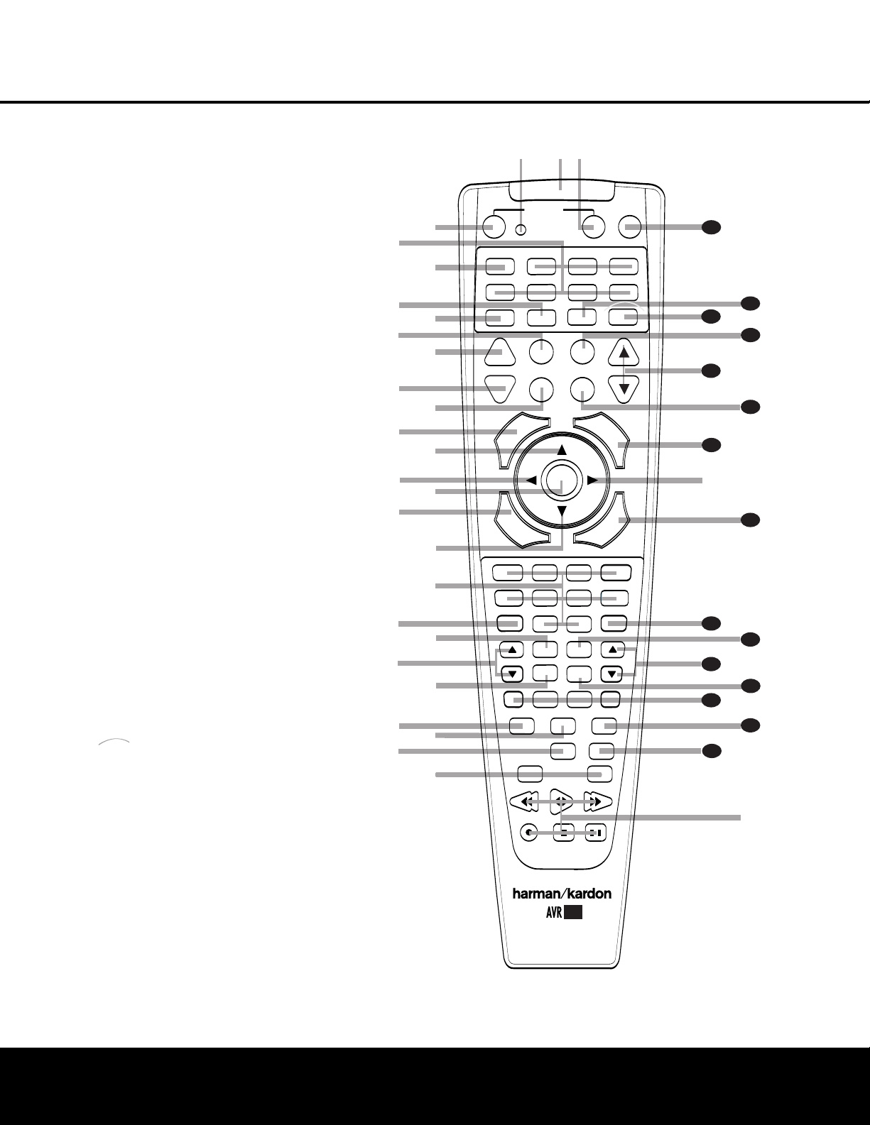
a Power Off Button
b I
R Transmitter Window
c P
rogram Indicator
d Power On Button
e Input Selectors
f AVR Selector
g A
M/FM Tuner Select
h Dim Button
i Test Button
j Sleep Button
k D
SP Surround Mode Selector
l Night Mode
m Channel Select Button
n
⁄
/
¤
Buttons
o
‹
/
›
Buttons
p Set Button
q Digital Select
r Numeric Keys
s Tuner Mode
t Direct Button
u Tuning Up/Down
v OSD Button
w Dolby Mode Selector
x DTS Digital Mode Selector
y Logic 7 Mode Select Button
z Skip Up/Down Buttons
` Transport Controls
R Stereo Mode Select Button
S DTS Neo:6 Mode Select
T
Macro Buttons
U
Disc Skip Button
V
Preset Up/Down
W
Clear Button
X
Memory Button
Y
Delay/Prev. Ch.
Z
Speaker Select
a
Spare Button
b
Volume Up/Down
c
TV/Video Selector
d
DMP Selector
e
6-Channel/8-Channel Direct Input
f
Mute
The
Bridge
TM
s
a
bc
d
e
f
g
h
j
n
n
p
o
o
q
r
t
v
`
32
30
29
28
36
3
7
38
39
z
x
35
POWER
MUTE
AVR
DVD
A
M/FM
CD
TAPE
VID 2
VCR
TV
CBL/SAT
6/8 CH
DMP
VID 1
VID 3
VID4
O
FF
O
N
SLEEP
T
/V
SURR.
CH.
VOL.
G
U
I
D
E
C
H
.
E
X
I
T
D
I
G
I
T
A
L
M
E
N
U
S
P
K
R
P
R
E
V
.
C
H
.
D
E
L
A
Y
SET
1
2
3
4
7
6
5
9
0
TUN-M
MEM
M2
M3
M4
D.SKIP
M1
DIRECT
OSD
TUNING
DOLBY SUR
DTS SUR
DTS NEO:6
STEREO
LOGIC 7
SKIP
UP
DOWN
PRESET
CLEAR
T
EST
NIGHT
22
44
00
8
l
u
DIM
i
k
m
34
33
w
y
41
40
31
42
®
The
Bridge
T
M
NOTES:
• The function names shown here are each button’s
feature when used with the AVR 240. Most buttons
have additional functions when used with other
devices. See pages 44–45 for a list of these
functions
.
•
T
o make it easier to follow the instructions that refer
to this illustration, a larger copy may be down-
loaded from the Product Support section for this
product at www
.har
mankardon.com.
REMOTE CONTROL FUNCTIONS
12 REMOTE CONTROL FUNCTIONS
I
MPORTANT NOTE:
T
he AVR 240’s remote may
b
e programmed to control up to seven devices,
including
the AVR 240. Before using the remote, it is
important to
remember to press the Input Selector
Button
e that corresponds to the unit you wish to
o
perate. In addition, the AVR 240’s remote is shipped
from the factory to operate the AVR 240 and most
Harman Kardon CD or DVD players and cassette
decks. The remote is also capable of operating a wide
v
ariety of other products using the control codes that
a
re part of the remote. Before using the remote with
other products, follow the instructions on page 41
to program the proper codes for the products in
your system.
It is also important to remember that many of the but-
tons on the remote take on different functions, depend-
ing on the product selected using the Device Control
Selectors. The descriptions shown here primarily detail
the functions of the remote when it is used to operate
the AVR 240. (See pages 42–45 for information about
alternate functions for the remote’s buttons.)
a Power Off Button: Press this button to place the
AVR 240 or a selected device in the Standby mode.
b IR Transmitter Window: Point this window
towards the AVR 240 when pressing buttons on the
remote to make certain that infrared commands are
properly received.
c Program Indicator: This three-color indicator is
used to guide you through the process of program-
ming the remote. (See page 41 for information on
programming the remote.)
d Power On Button: Press this button to turn on
the power to a device selected by pressing one of the
Input Selectors e.
e Input Selectors: Pressing one of these buttons
will perform three actions at the same time. First, if the
A
VR 240 is not tur
ned on,
this will power up the unit.
Next, it will select the source shown on the button as
the input to the AVR 240. Finally, it will change the
remote control so that it controls the device selected.
After pressing one of these buttons you must press
the
AVR Selector Button f again to operate the
AVR 240’s functions with the remote.
f AVR Selector: Pressing this button will switch the
remote so that it will operate the AVR 240’s functions. If
the A
VR 240 is in the Standby mode
,
it will also tur
n the
AVR 240 on.
g AM/FM Tuner Select: Press this button to select
the AVR 240’s tuner as the listening choice. Pressing
this button when the tuner is already in use will select
between the
AM and FM bands
.
h Dim Button: Press this button to activate the
D
immer function, which reduces the brightness of the
front panel display, or turns it off entirely. The first press
of the button shows the default state, which is full bright-
ness by indicating
VFD FULL in the Lower
D
isplay Line
ı.
Press the button again within five
s
econds to reduce the brightness by 50%, as indicated
by
VFD HALF showing in the Lower Display Line
ı. Press the button again within five seconds and the
main display will go completely dark. Note that this set-
t
ing is temporary, in that regardless of any changes, the
display will always return to full brightness when the AVR
is turned on. In addition, the
Power Indicator 2 will
always remain at full brightness regardless of the setting.
This is to remind you that the AVR is still turned on.
i Test Button: Press this button to begin the
sequence used to calibrate the AVR 240’s output levels.
(See pages 25, 29 and 38 for more information on
calibrating the AVR 240.)
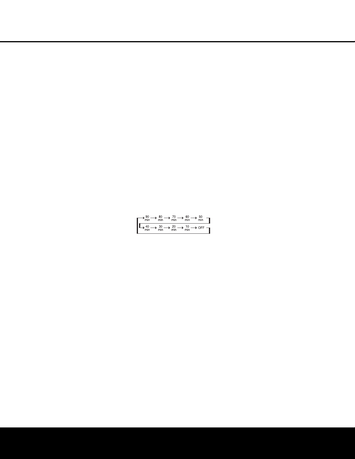
j Sleep Button: Press this button to place the unit
in the Sleep mode. After the time shown in the display,
the AVR 240 will automatically go into the Standby
mode. Each press of the button changes the time until
turn-off in the following order:
See page 31 for more information on the Sleep
Function. This button is also used to change channels
on your TV when the TV is selected.
k DSP Surround Mode Selector: Press this but-
ton to cycle through the DSP, VMAx and Stereo sur-
round modes such as Hall, Theater, VMAx Near and
F
ar,
and Surround Off. This button is also used to tune
channels when the TV is selected using the
device
Input Selector e.
l Night Mode: Press this button to activate the
Night mode.
This mode is available in specially
encoded digital sources, and it preserves dialogue
(center channel) intelligibility at low volume levels.
m Channel Select Button: This button is used to
start the process of setting the AVR 240’s output levels to
an exter
nal source
.
Once this button is pressed,
use the
⁄
/
¤
Buttons n
to select the channel being adjusted,
then press the Set Button p, followed by the
⁄
/
¤
Buttons
n again, to change the level setting. (See
pages 29 and 38 for more information.) However,
Harman Kardon recommends that you first perform
the EzSet+ procedure
,
as described on pages
23 to 25.
n
⁄
/
¤
Buttons: These multipurpose buttons are
u
sed to change or scroll through items in the on-
screen menus, make configuration settings such as
digital inputs or delay timing, or to select surround
modes. When changing a setting, first press the button
f
or the function or setting to be changed (e.g., press
t
he
D
SP Surround Mode Selector
k t
o select a
sound field mode or the
Digital Select Button q
to change a digital input) and then press one of these
buttons to scroll through the list of options or to
i
ncrease or decrease a setting. The sections in this
manual describing the individual features and functions
contain specific information on using these buttons
for each application.
o
‹/›
Buttons: These buttons are used to change
the menu selection or setting during some of the setup
procedures for the AVR 240.
p Set Button: This button is used to enter settings
into the AVR 240’s memory. It is also used in the
setup procedures for delay time, speaker configuration
and channel output level adjustment.
q Digital Select: Press this button to assign one
of the digital inputs
*(bg to a source. (See
pages 20 and 35 for more information on using
digital inputs.)
r Numeric Keys: These buttons serve as a 10-
button numeric keypad to enter tuner preset positions.
They are also used to select channel numbers when
TV, Cable or SAT has been selected on the remote, or
to select track numbers on a CD, DVD or LD player,
depending on how the remote has been programmed.
I Tuner Mode: Press this button when the tuner
is in use to select between automatic tuning and
manual tuning. When the button is pressed so that
MANUAL appears in the Lower Display Line ı,
pressing the
Tuning Buttons 9u will move the
frequency up or down in single-step increments
.
When the FM band is in use, pressing this button when
a station’s signal is weak will change to monaural
reception.
(See page 37 for more infor
mation.)
J Direct Button: Press this button when the tuner
is in use to start the sequence for direct entry of a sta-
tion’s frequency. After pressing the button, simply
press the proper
Numeric Keys r to select a sta-
tion.
(See page 37 for more information on the tuner.)

REMOTE CONTROL FUNCTIONS
REMOTE CONTROL FUNCTIONS
13
u Tuning Up/Down: When the tuner is in use, these
b
uttons will tune up or down through the selected fre-
quency band. If the
Tuner Mode Button s& has
been pressed so that
AUTO appears in the on-
screen display and
Lower Display Line ı, pressing
a
nd holding either of the buttons for three seconds will
c
ause the tuner to seek the next station with acceptable
signal strength for quality reception. When
MANUAL
appears in the Lower Display Line ı, pressing these
buttons will tune stations in single-step increments. (See
p
age 37 for more information.)
v OSD Button: Press this button to activate the
On-Screen Display (OSD) system used to set up or
adjust the AVR 240’s parameters.
w Dolby Mode Selector: This button is used to
select from among the available Dolby Surround pro-
cessing modes. Each press of this button will select
one of the Dolby Pro Logic II or IIx, or Dolby Virtual
Speaker modes or Dolby 3 Stereo. When a Dolby
Digital-encoded source is in use, the Dolby Digital
mode may also be selected. When the headphones
are in use, this button selects from among the Dolby
Headphone modes. (See pages 33–34 for the avail-
able Dolby surround mode options.)
x DTS Digital Mode Selector: When a DTS-
encoded digital source is selected, each press of this
button will scroll through the available DTS modes. The
specific choice of modes will vary according to whether
or not the source material contains DTS-ES 6.1
Discrete encoding. When a DTS source is not in use,
this button has no function. (See page 33 for the avail-
able DTS digital options.)
y Logic 7 Mode Select Button: Press this button
to select from among the available Logic 7 surround
modes. (See page 33 for the available Logic 7
options
.)
z Skip Up/Do
wn Buttons:
These buttons do not
have a direct function with the AVR 240, but when
used with a compatibly programmed CD or DVD
changer they will change to the previous disc in the
changer or carousel.
` Transport Controls: These buttons do not have
any functions for the AVR 240, but they may be
programmed for the forward/reverse play operation
of a wide variety of CD or DVD players
, and audio or
video cassette recorders
.
When the DMP
source is in use, these buttons may be used to oper-
ate some functions on a compatible iPod
®
if it is
docked in
The Bridge.
See page 37 for more
information on using .
W
hen the remote is used to control the AVR, or the
V
ID2 or VID3 device, by default these buttons are pro-
grammed to operate the DVD player. However, you
may use the Transport Control Punch-Through feature
described on page 43 to program these buttons to
o
perate another device’s transport controls when the
AVR, VID2 or VID3 has been selected.
R Stereo Mode Select Button: When the button
i
s pressed so that
S
URROUND OFF
a
ppears in
the
Lower Display Line ı, with only the Surr Off
Surround Mode Indicator
ˆ lit, the AVR will oper-
ate in a bypass mode with true, fully analog, two-chan-
nel left/right stereo mode with no surround processing
or bass management, unlike other modes where digi-
tal processing is used. When the button is pressed so
that
SURROUND OFF appears in the Lower
Display Line
ı,
with both the
DSP and Surr Off
Surround Mode Indicators
ˆ lit, you may enjoy a
two-channel presentation of the sound along with the
benefits of bass management. Depending on whether
your system is configured for 5.1 or 6.1/7.1 chan-
nels, the next press of the button will cause either
5 CH STEREO or 7 CH STEREO to
appear, and the stereo signal will be routed to all five
(or seven) speaker channels. (See page 34 for more
information on stereo playback modes.)
S DTS Neo:6 Mode Select: Press this button to
select a DTS Neo:6 mode. These modes take a two-
channel stereo- or matrix surround-encoded source
and create a full five-, six- or seven-channel sound
field. (See page 33 for the DTS Neo:6 options.)
T Macro Buttons: Press these buttons to store or
recall a “Macro”, which is a preprogrammed sequence
of commands stored in the remote. (See page 41 for
more information on storing and recalling macros.)
U Disc Skip Button: This button has no direct
function for the A
VR 240 but is most often used to
change to the next disc in a CD or DVD player when
the remote is programmed for that type of device.
(See page 42 for more infor
mation on using the
remote with products other than the AVR 240.)
V Preset Up/Down: When the tuner is in use,
press these buttons to scroll through the stations
programmed into the AVR 240’s memory. When
some source devices,
such as CD players
,
VCRs and
cassette decks, are selected using the device
Input
Selectors
e, these buttons may function as
Chapter Step or
Track Advance.
W Clear Button: Press this button to clear incorrect
entries when using the remote to directly enter a radio
station’
s frequency
.
X M
emory Button:
P
ress this button to enter a radio
s
tation into the AVR 240’s preset memory. First, tune
the desired station, and then press this button. Two
underline indicators will flash at the right side of the
Upper Display Line P, and within five seconds
p
ress the
N
umeric Keys
r f
or the preset number
between 01 and 30 that you wish to assign to the
station. (See page 37 for more information.)
Y Delay/Prev Ch.: Press this button to begin
the process for setting the delay times used by the
AVR 240 when processing surround sound. After
pressing this button, the delay times are entered by
pressing the Set Button p and then using the
⁄
/
¤
Buttons n to change the setting. Press the
Set Button p again to complete the process.
(See page 22 for more information.) However,
Harman Kardon recommends that you first perform
the EzSet+ procedure, as described on pages
23–25.
Z Speaker Select: Press this button to begin
the process of configuring the AVR 240’s bass man-
agement system for use with the type of speakers
used in your system. Once the button has been
pressed, use the
⁄
/
¤
Buttons n to select the
channel you wish to set up. Press the
Set Button
p and then select another channel to configure.
When all adjustments have been completed, press
the
Set Button p twice to exit the settings and
return to normal operation. (See page 26 for more
information.) However, Harman Kardon recommends
that you first perform the EzSet+ procedure, as
described on pages 23–25.
a Spare Button: This button has no direct function
for the AVR 240, but may be used by other devices.
b Volume Up/Down: Press these buttons to raise
or lower the system volume. By default, the
Volume
Up/Down Buttons
b are programmed at the fac-
tory to control the AVR 240’s volume, no matter which
source device has been selected (except TAPE). You
may reprogram these buttons to control the volume of
another device
,
such as your
TV
, using the Volume
Control Punch-Through instructions found on
page 43.
c TV/Video Selector: This button does not have a
direct function on the AVR 240, but when used with a
compatible
VCR,
DVD or satellite receiver,
pressing this
button will switch between the output of the device
and the external video input. Consult the owner’s man-
ual for your specific player or receiver for the details of
how it implements this function.
The
Bridge
TM
The
Bridge
T
M

d Digital Media Player (DMP)
Selector:
W
hen Harman Kardon’s (optional) is con-
n
ected to
D
igital Media Player (DMP)
Connector
e and a compatible Apple
®
iPod
®
is
docked in , pressing this selector will select
the iPod as the audio source input device for the
A
VR 240. In addition, if a video display is connected
to one of the
Video Monitor Outputs cV, the
iPod’s messages will appear on screen, and in the
Upper and Lower Display Lines PQ. The
⁄
/
¤
/
‹
/
› Buttons no, the Set Button
p and the Transport Controls ` may be used
to navigate the iPod and to operate many functions.
See page 37, and the manuals for The Bridge and
your iPod for more information.
e
6-Channel/8-Channel Direct Input: Press
this button to select the device connected to the
6/8-Channel Direct Inputs j.
(See page 31 for
more information.) When the device connected to the
6/8-Channel Direct Input j is also a video source,
such as a DVD or DVD-Audio player with an onboard
audio decoder, you must first select that video source
by pressing one of the
Input Selectors e, then
press this button to choose the device connected to
the
6/8-Channel Direct Input j as the audio
source. Note that if you desire, you may select any
video source to be used in conjunction with the
6/8-
Channel Direct Input
j as the audio source.
f Mute: Press this button to momentarily silence
the AVR 240 or TV set being controlled, depending on
which device has been selected. When the AVR 240
remote is being programmed to operate another device,
this button is pressed with the
Input Selector Button
e to begin the programming process. (See page
41 for more information on programming the remote.)
The
Bridge
T
M
The
Bridge
TM
The
Bridge
TM
The
Bridge
T
M
REMOTE CONTROL FUNCTIONS
14 REMOTE CONTROL FUNCTIONS

INSTALLATION AND CONNECTIONS
System Installation
After unpacking the unit, locating it in a place with ade-
quate ventilation and placing it on a solid surface capable
of supporting its weight, you will need to make the con-
nections to your audio and video equipment.
IMPORTANT NOTE: For your personal safety and to
avoid possible damage to your equipment and speakers,
it is always a good practice to turn off and unplug the
AVR and ALL source equipment from the AC output
b
efore making any audio or video system connections.
Audio Equipment Connections
We recommend that you use high-quality interconnect
cables when making connections to source equipment
and recorders to preserve the integrity of the signals.
1. Connect the analog outputs of a CD player to the
CD Audio Inputs
™
.
NOTE: When the CD player has both fixed and vari-
able audio outputs, it is best to use the fixed output
unless you find that the input to the receiver is so
low that the sound is noisy, or so high that it is
distorted.
2. Connect the analog Play/Out jacks of a cassette
deck, MD, CD-R or other audio recorder to the
Tape Input Jacks ¢. Connect the analog
Record/In jacks on the recorder to the
Tape
Output Jacks
£ on the AVR 240.
3. Connect the output of any digital sources such as
a CD or DVD changer or player, advanced video
game, a digital satellite receiver, HDTV tuner or
digital cable set-top box or the output of a com-
patible computer sound card to the
Optical and
Coaxial Digital Audio Inputs bg*(.We
recommend connecting the coaxial digital audio
output of your DVD player to the
Coax 1 Digital
Audio Input
·,
since that digital input is
assigned to the DVD source by default. The Video
2/Cable/Sat source defaults to the
Optical 1
Digital Audio Input
g. If your cable television
set-top box or satellite receiver is equipped with
an optical digital audio output, we recommend that
you connect it to this input to obtain the benefits
of higher-quality digital audio (such as PCM, Dolby
Digital 2.0 or Dolby Digital 5.1 signals when broad-
cast by your cable or satellite provider).
4. Connect the
Coaxial or Optical Digital Audio
Outputs
·a on the rear panel of the
A
VR
240 to
the matching digital input connections on a CD-R or
MiniDisc or other digital recorder.
5.
Assemble the
AM Loop
Antenna supplied with the
unit so that the tabs at the bottom of the antenna
loop snap into the holes in the base
.
Connect it to
the
AM Antenna Terminals c.
6. Connect the supplied FM antenna to the
FM (75-
ohm)
Connection ¡. The FM antenna may be an
e
xternal roof antenna, an inside powered or wire-
lead antenna or a connection from a cable TV sys-
tem. If the antenna or connection uses 300-ohm
twin-lead cable, you must use the 300-ohm-to-75-
ohm adaptor supplied with the unit to make the
connection.
7. With the AVR 240 turned off, connect the optional
Harman Kardon to
Digital Media
Player (DMP) Connector
e. Your compatible
iPod
®
may be docked in when you wish to
use it as an audio source device. Video materials
stored on the iPod may not be viewed when The
Bridge is in use.
8. Connect the front, center, surround and surround
back speaker outputs
ª‚⁄¤ to the respec-
tive speakers.
To ensure that all the audio signals are carried to your
speakers without loss of clarity or resolution, we sug-
gest that you use high-quality speaker cable. Many
brands of cable are available and the choice of cable
may be influenced by the distance between your
speakers and the receiver, the type of speakers you
use, personal preferences and other factors. Your dealer
or installer is a valuable resource to consult in select-
ing the proper cable.
Regardless of the brand of cable selected, we recom-
mend that you use a cable constructed of
multistrand
copper with a gauge of 14 or smaller.
Remember that
in specifying cable, the lower the number, the thicker
the cable.
Cable with a gauge of 16 may be used for short runs
of less than 10 feet. We do not recommend that you
use cables with an
A
WG equivalent of 18 or higher
,
due to the power loss and degradation in perfor
mance
that will occur.
Cables that are run inside walls should have the appro
-
priate markings to indicate listing with UL, CSA or other
appropriate testing agency standards
.
Questions about
running cables inside walls should be referred to your
installer or a licensed electrician who is familiar with
the NEC and/or the applicable local building codes in
your area.
When connecting wires to the speakers
,
obser
ve
proper polarity. Note that the positive (+) terminal of
each speaker connection may carry a specific color
c
ode, as noted on page 8. However, many speakers
s
till use a red terminal for the positive (+) connection.
Connect the “negative” or “black” wire to the same ter-
minal on both the receiver and the speaker.
NOTE: While most speaker manufacturers adhere to
an industry convention of using black terminals for
negative and red ones for positive, some may vary
from this configuration. To ensure proper phase and
o
ptimal performance, consult the identification plate on
your speaker or the speaker’s manual to verify polarity.
If you do not know the polarity of your speaker, ask
your dealer for advice before proceeding, or consult
the speaker’s manufacturer.
We also recommend that the length of cable used
to connect speaker pairs be identical. For example,
use the same length piece of cable to connect the
front-left and front-right or surround-left and sur-
round-right speakers, even if the speakers are a
different distance from the AVR 240.
9. Connections to a subwoofer are normally made
via a line-level audio connection from the
Subwoofer Output • to the line-level input of a
subwoofer with a built-in amplifier. When a passive
subwoofer is used, the connection first goes to a
power amplifier, which will be connected to one or
more subwoofers. If you are using a powered
subwoofer that does not have line-level input con-
nections, follow the instructions furnished with the
speaker for connection information.
10. If an external multichannel audio source with 5.1,
6.1 or 7.1 outputs such as an external digital
processor/decoder, DVD-Audio or SACD player
is used, connect the outputs of that device to
the
6/8-Channel Direct Inputs j.
Video Equipment Connections
Video equipment is connected in the same manner as
audio components
.
The use of high-quality interconnect
cables is recommended to preserve signal quality.
1. Connect a VCR’s, DVD recorder’s, personal video
recorder’s or other video source’s audio and video
Play/Out jacks to the
Video 1 Audio/Video and/or
S-Video Input Jacks OX on the rear panel. The
Audio and
Video Record/In jacks on the recorder
should be connected to the
Video 1 Audio/Video
and/or S-Video Output Jacks QY on the
A
VR 240.
Although any video device may be connected to
these jacks, we recommend connecting your video
recorder so that you may take advantage of the
fact that the remote control is preprogrammed
with video recorder product codes for the Video 1
device
.
2. Connect the analog audio and video outputs of a
satellite receiver, cable TV converter, television set
The
Bridge
TM
The
Bridge
T
M
The
Bridge
T
M
INSTALLATION AND CONNECTIONS 15

16 INSTALLATION AND CONNECTIONS
o
r any other video source to the
V
ideo 2
A
udio/Video and S-Video Input Jacks
R
Z
.
Although any video device may be connected to
these jacks, we recommend connecting your cable
TV converter or satellite receiver so that you may
t
ake advantage of the fact that the remote control is
preprogrammed with the product codes of these
device types for the Video 2 device.
3
. Connect the analog audio and video outputs of
a television or other video device to the
Video 3
Audio
and Video Input Jacks Ub on the rear
panel. Although any video or audio device may be
connected to these jacks, we recommend connect-
ing your television so that you may take advantage
of the fact that the remote control is preprogrammed
with
TV product codes for the Video 3 device.
Important: If you are only using the television as a
display device (i.e., if you receive your television
programs through a cable box or satellite receiver),
do not connect the television’s outputs to the
Video
3 Audio
and Video Input Jacks Ub, or to any
other inputs on the AVR 240.
4. Connect the analog audio and video outputs of a
DVD or laser disc player to the
DVD Audio/Video
and S-Video Inputs
dW.
5. Connect the digital audio outputs of a DVD player,
satellite receiver, cable box or HDTV converter to
the appropriate
Optical or Coaxial Digital Inputs
bg*(. Remember that the DVD source
defaults to the
Coaxial 1 Digital Input ·, and
the Video 2/Cable/Sat source defaults to the
Optical 1 Digital Audio Input g. All other
sources default to their analog inputs, although
any source may be assigned to any digital audio
input on the receiver.
6. Connect the
Video and/or S-Video Monitor
Output
cV jacks on the receiver to the compos
-
ite or S-video input of your television monitor or
video projector.
7. If both your video display monitor and at least one
video source device, such as a DVD player or
HDTV set-top box, is equipped with component
video capability, then you may connect the compo-
nent video outputs of the device to one of the two
Component Video Inputs ›fi.
It is recommended that you connect a DVD player or
a digital recorder to the
Component Video 1 Inputs
›, as this input is assigned to the DVD, CD, Tuner
and
T
ape sources by default. Thus, whenever any of
these sources is selected, you may view the compo-
nent video output of the device connected to the
Component Video 1 Inputs ›, enabling you
to view and listen to different sources.
S
imilarly, it is recommended that you connect any
o
ther audio/video device, such as a DVD-Audio or
SACD player or HDTV set-top box, to the Video 1,
Video 2 or Video 3 sources, or the 6-/8-channel
direct inputs, as the
Component Video 2 Inputs fi
a
re assigned to the Video 1, Video 2, Video 3 and
6-/8-channel source audio inputs by default.
However, you may connect any component video
source to either set of component video inputs, as
they are assignable to any source. You will still need to
connect either the analog or digital audio outputs, or
the 6-/8-channel audio outputs, of your component
video device to the analog audio inputs corresponding
to the source (such as DVD or Video 2 for a cable
converter box), or to any of the Optical or Coaxial
Digital Audio Inputs
bg*(.
8. If the component video inputs are used, connect
the
Component Video Monitor Outputs ‹ to
the component video inputs of your TV, projector
or display device.
9. If you have a camcorder, video game or other
audio/video device that is connected to the AVR on
a temporary rather than permanent basis, connect
the audio, video and digital audio outputs of that
device to the
Video 4 Inputs *(ÓÔ on the
front panel. A device connected here is selected as
the Video 4 input, and the digital inputs must be
assigned to the Video 4 input. (See page 20 for
more information on input configuration.)
VIDEO CONNECTION NOTES:
• When the component video jacks are used, the on-
screen menus are not visible and you must switch
to the standard composite or S-video input on your
TV to view them.
• The AVR 240 will accept either standard composite,
S-video or Y/Pr/Pb component video signals. How-
ever
,
it will not convert any of these signals to a
different format.
• When connecting a video source to the AVR 240,
you may use either composite,
component or S-
video, but only one type of video may be connected
for each device.
•
When more than one video format is used, it is
necessary to make a separate connection from
the
A
VR to your video display for each format.
F
or example
,
if both composite and component
sources are connected to the AVR 240, both the
Composite and Component Video Monitor
Outputs
‹V must be connected to the appro
-
priate inputs on your video display.
System and Power Connections
The AVR 240 is designed for flexible use with external
control components.
Main Room Remote Control Extension
If the receiver is placed behind a solid or smoked
glass cabinet door, the obstruction may prevent the
remote sensor from receiving commands. In this
event, an optional remote sensor may be used.
Connect the output of the remote sensor to the
Remote IR Input ∞ jack.
If other components are also prevented from receiving
remote commands, only one sensor is needed. Simply
use this unit’s sensor or a remote eye by running a
connection from the
Remote IR Output § jack to
the Remote IR Input jack on Harman Kardon or other
compatible equipment.
AC Power Connections
This unit is equipped with two accessory AC outlets.
They may be used to power accessory devices, but
they should not be used with high-current-draw equip-
ment such as power amplifiers. The total power draw
to each outlet may not exceed 100 watts.
The
Switched AC Accessory Outlet ‡ will receive
power only when the unit is on. This is recommended
for devices that have no power switch or a mechanical
power switch that may be left in the “ON” position.
NOTE: Many audio and video products go into a
Standby mode when they are used with switched out-
lets, and cannot be fully turned on using the outlet
alone without a remote control command.
The
Unswitched AC Accessory Outlet ° will
receive power as long as the unit is plugged into a
powered AC outlet.
Once the
AC Power Cord fl is connected, you are
almost ready to enjoy the AVR 240’s incredible power
and fidelity!
INSTALLATION AND CONNECTIONS

SYSTEM CONFIGURATION 17
SYSTEM CONFIGURATION
W
hen all audio, video and system connections have
b
een made, the final steps before listening to your new
AVR are to make the configuration adjustments that
tailor the unit to the other components in your system
as well as to accommodate your personal listening
p
references. A few minutes spent to correctly calibrate
and configure your system will greatly add to your lis-
tening pleasure.
Speaker Selection and Placement
While the most seamless surround sound reproduction
comes from the use of speakers with identical or care-
fully matched driver elements at each position, no
matter which brand or type of speakers you prefer, it
is always best to use the same model or series for
the left front, center and right front speakers. Similarly,
it is also desirable to use the same model or series
for the surround speakers. This ensures that the sound-
stage will be relatively seamless and it eliminates the
possibility of sonic discordance when a sound moves
from one side of the room to the other.
Speaker Placement
Once you have selected your speakers, it is important
that they be placed in positions that enable them to do
the best job of reproducing the sound as it was meant
to be heard, regardless of the program content.
Particularly in multichannel 5.1, 6.1 or 7.1 systems,
the placement of speakers can have a noticeable
impact on the accuracy of the surround process.
When placing your speakers in a listening room, pic-
ture an imaginary circle starting at the center of your
video screen that arcs around the room with the prime
listening position, or “sweet spot,” at the center of the
circle. Depending on the number of speakers in your
system, there is a recommended placement along the
circle for each speaker, though the specific construc-
tion of your room,
taking into account the available
walls
,
bookcases,
or floor space at which the speakers
may be placed will obviously have some impact on
where the speakers are ultimately located. As a gener-
al rule,
tr
y to place all speakers so that they are posi-
tioned at the same height as your ears when you are
seated at the prime listening position.
Use the following suggestions as a guide, and make
the changes needed to fit the speakers to your room.
Don’t be afraid to experiment a bit until you find the
right combination of locations that works for you. At
the end of the day, there is no real “right” or “wrong”
place to put the speakers; work to optimize their loca-
tions so that audio moves across the front of the room
smoothly
,
without seeming to jump from one speaker
to another
.
Center Channel Speaker
The ideal location for the center channel speaker is at
“0 degrees” in our circle, directly in front of the prime
listening position.
Place the center channel speaker as
c
lose to the top (or bottom) of the video screen as
p
ossible so that when you position the front left/right
speakers the tweeters of all three front channel speak-
ers are within 24” of one another.
F
ront Left/Right Speakers
The recommended placement for front left/right
speakers is at the 30-degree position with reference
to the center channel speaker. The distance between
t
hem should be about the same as the distance from
the center channel speaker to the prime listening
position.
Although the natural tendency is to place the speakers
so they are parallel to the wall behind them, and thus
in line with the video screen, the preferred placement
is to angle the speakers slightly (“toe in”) so that they
point at the prime listening position.
Surround Speakers for 5.1 Systems
In a 5.1 surround system, an additional pair of
left/right speakers is added. Although many believe
that these speakers should be placed at the rear of
the room, the preferred position for them is at the
sides of the room, with rear placement a second
o
ption when room conditions prevent the use of side-
m
ounted surround speakers.
When side-wall placement is possible, place the
left/right surround speakers at a point that is 110
d
egrees along our circle from the center of the video
screen. This translates to placing them to the side and
slightly behind your preferred listening position. If pos-
sible, angle the speakers in slightly so that they are
pointing towards the listener’s ears.
If it is not possible to place the surround speakers at
the sides of the room, the alternate position is at the
back of the room, at a spot that is about 150 degrees
around our circle from the center of the video screen.
Another way to spot the optimal, alternate rear wall
mounting position is to place the left surround speaker
on the back wall so that it points directly at the front
right speaker, and to have the right surround speaker
point directly at the front left speaker. If possible,
aim the surround speakers so that they point “in”
toward the listening area, rather than perpendicular
to the walls.
Center Speaker
Video Screen
Front Right
Speaker
Front Left
Speaker
Side Surround
Left Speaker
Alternate placement
for Side Surround
Left Speaker
Side Surround
Right Speaker
Alternate placement
for Side Surround
Right Speaker
110 °
150°
110 °
150°
30° 30°
5.1 Placement Diagram
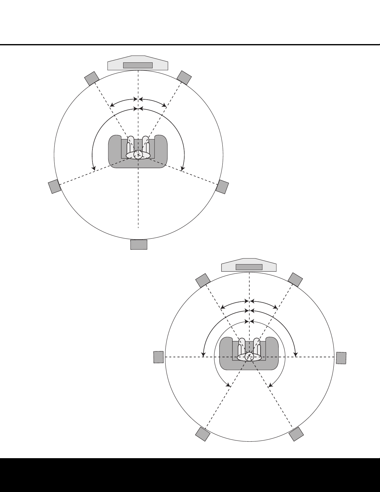
18
SYSTEM CONFIGURATION
SYSTEM CONFIGURATION
Surround Speakers for 6.1 Systems
A 6.1 surround speaker adds an additional center
back surround speaker to the system, enabling you to
enjoy the benefits of advanced surround modes such
as Dolby Digital EX, DTS-ES and Harman Kardon’s
proprietary Logic 7/7.1 processing.
To step up to a 6.1 system, first place the speakers
for a 5.1 system,
as shown on page 14.
The “sixth”
speaker should ideally be placed at the center of the
room’s rear wall, pointing directly toward the front
center channel speaker.
Surround Speakers for 7.1 Systems
F
or the ultimate home theater experience,
a 7.1 sur
-
round system uses both traditional surround left/right
channels and a surround back left/right speaker pair.
In a 7.1 system,
the front left/center/right speakers
remain in the same place as they would be for a 5.1
or 6.1 system, but due to the number of speakers
involved, the placement of the surround speakers is
different.
In a 7.1 system, you should place the main surround
left/right speakers at the 90-degree point on our cir-
cle. A good way to visualize proper surround speaker
positioning for 7.1 is to place the speakers directly to
the left and right of the ears of someone sitting in the
prime listening spot. The two speakers should ideally
face toward each other
.
T
he additional set of Surround Back Left/Right speak-
e
rs is placed at about 150 degrees on the circle,
pointing inward toward the listening area. The easiest
way to visualize the placement of these speakers is to
place the surround back left speaker directly opposite
t
he right front speaker and to place the surround back
left speaker directly opposite the left front speaker.
Since subwoofers produce nondirectional sound, they
m
ay be placed almost anywhere in a room. Actual
placement should be based on room size and shape
and the type of subwoofer used. One method of find-
ing the optimal location for a subwoofer is to begin by
placing it in the front of the room, about six inches
from a wall, or near the front corner of the room.
Another method is to temporarily place the subwoofer
at your normal listening position, and then walk
around the room until you find a spot where the sub
-
woofer sounds best. Place the subwoofer in that spot.
You should also follow the instructions of the sub-
woofer’s manufacturer, or you may wish to experi-
ment with the best location for a subwoofer in your
listening room.
NOTES ON SPEAKER PLACEMENT:
1. The limitations of your listening room, including the
placement of walls and furniture, may make it diffi-
cult to follow the speaker placement suggestions
shown above. Depending on the specific layout of
Center Speaker
Video Screen
Front Right
S
peaker
Front Left
S
peaker
Side Surround
Left Speaker
Side Surround
Right Speaker
Back Surround
Speaker
L
istening Position
1
10° 1 10°
30°
30°
6.1-Channel System
Center Speaker
Video Screen
Front Right
Speaker
Front Left
Speaker
Side Surround
Left Speaker
Back Surround
Left Speaker
Side Surround
Right Speaker
Back Surround
Right Speaker
90°
150°
90°
150°
30° 30°
7.1-Channel System

SYSTEM CONFIGURATION
19
SYSTEM CONFIGURATION
t
he room, here are some ways to compensate for
u
nusual conditions:
• Try to follow the suggested placement, but move
the speakers within a few feet from the preferred
locations.
•
Regardless of where they are placed, always try
to make certain that the main surround speakers
are the same distance from the front speakers.
(For example, try not to have the right surround
s
peaker further back into the room than the left
s
urround speaker.)
• If it is not possible to wall-mount or place speak-
ers on a shelf, consider the use of optional floor
stands, available for many speakers.
2. When using ceiling mounted in-wall speakers, fol-
low the same guidelines shown for conventional
floor or shelf-mounted speakers.
System Setup
Once the speakers have been placed in the room and
connected, the remaining steps in the setup process
are to configure each source input to match the physi-
cal connections you have made, select a surround
mode and run the EzSet+ procedure, which will auto-
matically program the AVR 240’s bass management
system for the type of speakers used in your system,
calibrate the output levels, and set the delay times
used by the surround sound processor.
You are now ready to power up the AVR 240 to begin
these final adjustments.
1. Make certain that the
AC Power Cord fl is
firmly inserted into an unswitched AC outlet. To
maintain the unit’s safety rating, DO NOT replace
the power cord with one that has a lower current
capacity.
2. Press the
Main Power Switch 1 in until it
latches and the word
“OFF” on the top of the
switch disappears inside the front panel. Note
that the
P
ower Indicator
2 will tur
n amber,
indicating that the unit is in the Standby mode.
3.
Remove the protective plastic film from the front-
panel lens. If left in place, the film will affect the
perfor
mance of your remote control.
4.
Install the three supplied
AAA batteries in the
remote as shown. Be certain to follow the (+)
and (–) polarity indicators that are on the top of
the battery compartment.
5
. Turn the AVR 240 on either by pressing the
S
tandby/On Switch
2 o
n the front panel, or
via the remote by pressing the
Power On Button
d, the AVR Selector f or any of the Input
Selectors
deg. When the unit is turned
o
n, the entire list of options will briefly light for both
the Input Indicators Ú and the Surround
Mode Indicators
ˆ. After a few seconds, the
majority of those indicators will go dark, leaving
o
nly the indications for the active surround mode
a
nd input illuminated. The
D
isplay Lines
Ù
ı
will display the unit’s status, the Power Indicator
2 will turn blue, and the accent light inside the
Volume Control Ò will also light up to remind
you that the unit is turned on.
Using the On-Screen Display
When making the following adjustments, you may find
it easier to use the AVR 240’s on-screen display sys-
tem. These easy-to-read displays give you a clear pic-
ture of the current status of the unit and make it easy
to see which selection you are making.
To view the on-screen menus, make certain that you
have made a connection from the
Video or S-Video
Monitor Out Jack
cV on the rear panel to the
composite or S-video input of your TV or projector.
In order to view the AVR 240’s displays, the correct
video source must be selected on the video display.
The on-screen menus are not available when a com-
ponent video display is in use.
IMPORTANT NOTE: When viewing the on-screen
menus using a CRT-based projector, plasma display or
any direct-view CRT monitor or television, it is important
that they not be left on the screen for an extended period
of time. The constant display of a static image such as
these menus or other still images may cause the image
to be per
manently “bur
ned into”
the projection tubes
,
plasma screen or CRT. This type of damage is not cov-
ered by the AVR 240 warranty and may not be covered
by the projector/TV set’s warranty.
The AVR 240 has two on-screen display modes,
“Semi-OSD” and “Full-OSD.” When making configura-
tion adjustments, it is recommended that the Full-OSD
mode be used. This will place a menu on the screen,
making it easier to view the available options.
Making Configuration Adjustments
The full-OSD system is available by pressing the
OSD Button v.
When this button is pressed,
the
MASTER MENU (Figure 1) will appear, and
adjustments are made from the individual menus.
Figure 1
The semi-OSD system is also available, allowing you
to make adjustments directly, by pressing the appro-
priate buttons on the front panel or remote control for
the specific parameter to be adjusted. For example,
to change the digital input for any of the sources,
press the
Digital Select Button q and then
press the
⁄
/
¤
Buttons n to scroll through the
list of options as they appear in the on-screen display
or the
Upper Display Line P.
To use the full-OSD menu system, press the
OSD
Button
v. When the menu is on the screen, press
the
⁄
/
¤
Buttons n until the on-screen
›
cursor
is next to the item you wish to adjust, and then press
the
Set Button p to adjust that item. The menus
will remain on the screen for 20 seconds, and then
they will “time-out” and disappear from
the screen. The
time-out may be increased to as much as 50 seconds
by going to the
ADVANCED SELECT menu,
and changing the item titled
FULL OSD TIME
OUT
(see page 38).
When the full-OSD menu system is used,
OSD ON
will appear in the Upper Display Line P to remind
you that a video display must be used. When the
semi-OSD system is used in conjunction with the dis-
crete configuration buttons, the on-screen display will
show the current menu selection.
That selection will
also be shown in the
Upper Display Line P or
the
Lower Display Line ı, depending on which
parameter is being adjusted.
Setting the System Configura
tion Memory
The
A
VR 240 features an advanced memor
y system
that enables you to establish different configurations
depending on the input source or the surround mode.
This flexibility enables you to customize the way in
which you listen to various types of program materials
and have the
AVR 240 memorize those settings. This
means, for example, that if you mostly use your DVD
player for watching movies, you may configure your
DVD source to default to a particular digital input,
speaker size configuration and surround mode each
time you select it, optimizing your home theater for
cinematic materials. Once these settings are made,
they will automatically be recalled whenever you select
that input.
** MASTER MENU **
INPUT SETUP
AUDIO SETUP
SURROUND SELECT
EzSet+
MANUAL SETUP
ADVANCED

20 SYSTEM CONFIGURATION
SYSTEM CONFIGURATION
20 SYSTEM CONFIGURATION
I
n addition to the previously mentioned settings, which
always vary with the input, you may also choose to set
different speaker size configurations for each input. In
most cases, this is not required, thus the factory
d
efault keeps these settings the same for all inputs.
However, should you wish to have these settings
c
hange for any one, or all, inputs, follow the instruc-
tions shown on page 27 to select the Independent
mode for speaker configuration.
The first time you use the AVR 240, we recommend
that you take advantage of the simplicity of configuring
the system using the EzSet+ process, which takes the
guesswork out of speaker size and delay settings, and
balances the speaker output levels to tailor the AVR’s
sound presentation to your specific system and room.
Before beginning the EzSet+ procedure, there are a
few adjustments that need to be made to ensure
accurate results.
The factory default settings for the AVR 240 have all
inputs configured for an analog audio input except
for the DVD input, where the
Coaxial Digital Audio
Input 1
b is the default, and the Video 2 input,
where the
Optical Digital Audio Input 1 g is the
default. The default speaker settings are for “Small”
at all positions, and the subwoofer on.
The default surround mode setting for all sources
using an analog input is the Logic 7 Music mode.
Dolby Digital or DTS will always be automatically
selected anytime a source with digital encoding in that
format is in use. When a Dolby Digital 2.0 source is
detected, the AVR 240 will automatically add Dolby
Pro Logic II or IIx processing. Once a surround mode
is selected for a particular source, the AVR 240 will
default to that surround mode the next time the source
is selected, unless the input signal is in a Dolby Digital
or DTS digital format. For Dolby Digital and DTS mate-
rials, the AVR 240 will default to the surround mode
encoded in the bitstream. As explained on pages
35–36,
you may select from a limited number of
other surround modes for these materials. If you wish
to have the AVR 240 default to one of these alternate
surround modes each time a Dolby Digital or DTS
source is encountered, you may use the Default
Surround Mode setting in the
ADVANCED
SELECT
submenu (see page 39).
Before using the unit, you will probably want to pro-
gram the settings for most inputs so that they are
properly configured to reflect the use of digital or ana-
log audio inputs, component video inputs and the sur-
round mode specifics of your home theater system.
Remember that since the
A
VR
240 memorizes these
settings for each input independently, you will need to
make some of these adjustments for each input used.
However
,
once they are made, further adjustment is
only required when system components are changed.
T
o make this process as quick and easy as possible,
w
e suggest that you use the full-OSD system with the
on-screen menus, and step through each input. It is
also a good idea to set the configuration data in the
order these items are listed in the
MASTER
M
ENU
,
as some settings require a specific entry
in a prior menu item. It is recommended that you
record your settings for each input using the work-
sheets in the appendix to this manual, in the event
t
here is a power loss or if you need to reenter the
s
ettings for some other reason.
Input Setup
The first step in configuring the AVR 240 is to configure
each input. Once an input is configured,
all settings for
the Digital Input, Component Video Input and Surround
Mode will “attach” themselves to that input and be
stored in a nonvolatile memory. The later selection of
that input will automatically recall those settings. For
that reason, the procedures described below must be
repeated for each input source so that you have the
opportunity to customize each source to your specific
listening requirements. However, once made, they
need not be changed again unless you need to alter
a setting.
When using the full-OSD system to make the setup
adjustments, press the
OSD Button v once so that
the
MASTER MENU (Figure 1) appears. The
›
cursor will be next to the INPUT SETUP line.
Press the
Set Button p to enter the menu and the
INPUT SETUP menu (Figure 2) will appear on
the screen. Press the
‹
/
›
Buttons o until the
desired input name appears in the highlighted video,
as well as being indicated in the front-panel
Input
Indicators
Ú. If the input will use the standard left/
right analog inputs and will not use component video,
no further adjustment is needed.
NOTE: The DIGITAL IN line will default to
COAXIAL 1 when the DVD input is selected.
Similarly, when the Video 2 input is selected,
the
DIGITAL IN line will default to
OPTICAL 1.
Figure 2
The AVR 240 offers you the opportunity to rename
any source (except the tuner) to customize it for your
particular equipment configuration,
e
.g. to designate
t
he source input to which you have connected a VCR,
o
r a DVD-Audio player. This name will appear in the
Upper Display Line P and in the on-screen display
whenever that source input is selected. If you wish to
rename a source, press the
¤ Button n until the
› c
ursor is pointing to the
N
AME:
l
ine. Press the
Set Button p. A flashing box will appear. Press the
⁄ Button n to scroll through the letters of the
alphabet first in upper case, then in lower case, then
t
he numerals 0 through 9, and then followed by the
s
ymbols ! ‘ ( ) * + , - . / ; < = > ? [ ] and then a
blank space. Use the
¤ Button n to scroll in the
reverse order. Use the
‹/› Buttons o to move
from one character to the previous or following char-
acter. You may create a name of up to 14 characters,
including spaces. Press the
Set Button p when
you have finished entering the name, and then press
the
¤ Button n to proceed to the next setting.
If your system includes any sources that are equipped
with Y/Pr/Pb component video outputs, the AVR 240
is able to switch them to send the proper signals to
your video display. Each of the two
Component
Video Inputs
›fi may be assigned to a source for
added system flexibility. The
Component Video 1
Input
› may be assigned to any one of the DVD,
Tuner, CD or Tape inputs. The
Component Video 2
Input
fi may be assigned to any one of the Video 1
(VCR), Video 2 (Cable/Sat), Video 3 (TV) or 6/8-
Channel Direct inputs. If your system does not include
component video at this time, or if you do not need to
change these defaults, press the
¤ Button n to
go to the next setting.
To change the Component Video assignment, first
make certain that the cursor is pointing to the
COMPONENT IN line on the menu screen, and
then press the
‹/› Buttons o until you see the
desired input.
When the desired component video
input has been selected, press the
¤ Button n
to go to the next setting.
If you wish to associate one of the digital inputs with
the selected input source
,
press the
¤
Button n
on the remote while the INPUT SETUP menu
(Figure 2) is on the screen, and the on-screen cursor
will drop down to the
DIGITAL IN line. Press
the
‹
/
›
Buttons o until the name of the desired
digital input appears. To return to the analog input,
press the buttons until the word
ANALOG appears.
When the correct digital input jack appears, press the
¤
Button n once so that the
›
cursor appears
next to
BACK
TO MASTER MENU
,
and
press the
Set Button p.
T
o change the digital input at any time using the dis-
crete function buttons and the semi-OSD system,
press the
Digital Select Button q on the remote.
Within five seconds, make your input selection using
* INPUT SETUP *
INPUT :DVD
NAME:
COMPONENT IN:COMP V 1
DIGITAL IN:COAXIAL 1
AUTO POLL :OFF
BACK TO MASTER MENU

SYSTEM CONFIGURATION 21
SYSTEM CONFIGURATION
SYSTEM CONFIGURATION 21
SYSTEM CONFIGURATION
the
⁄
/
¤
Buttons n until the desired digital or
a
nalog input is shown in the
U
pper Display Line
P
and in the lower line of the on-screen display. Press
the
Set Button p to enter the new digital input
assignment.
Some digital video input sources, such as a cable box
or HDTV set-top, may change between analog and
digital outputs, depending on which channel is in use.
The AVR 240’s Auto Polling feature allows you to
a
void losing the audio feed when this happens by
automatically searching both analog and digital con-
nections for a signal. Digital audio is the default, and
the unit will automatically switch to the analog audio
if the digital audio stream stops.
In cases where only a digital source is used, such as
for a DVD player, you may wish to disable the Auto
Polling feature to prevent the AVR from trying to “find”
an analog source when the digital source is paused.
To turn Auto Polling off for any input, first make certain
that the
›
cursor is pointing to the AUTO POLL
line on the menu screen. Next, press the
‹
/
›
Buttons o so that OFF appears. To restore the
Auto Polling feature, repeat the procedure at any time
so that
ON appears.
When DMP has been selected as the source
input, an additional line will appear in this menu that
lets you select whether you wish to allow your iPod to
continue charging while docked in when the
AVR 240 is turned off and placed in Standby mode.
To make your selection, press the
⁄/¤ Buttons
n until the › cursor is next to the line reading
RECHARGE IN ST-BY. Press the ‹/›
Buttons o until the word YES appears if you
wish charging to continue, and the blue lighting on
The Bridge will remain lit when the AVR 240 is in
Standby mode to indicate that charging is taking
place.
The default setting is
NO,
in which the docked
iPod will not continue to charge when the AVR 240
is turned off, even though remains connected
to the AVR.
When all needed adjustments have been made, press
the
¤
Button n until the
›
cursor is next to
BACK TO MASTER MENU to continue with
the system configuration.
Audio Setup
This menu allows you to configure the tone controls
.
If
you do not wish to change those settings at this time,
proceed to the next menu screen.
However,
to make
configuration changes to those parameters
,
make cer
-
tain that the
MASTER MENU (Figure 1) is on
screen with the
› cursor pointing to the AUDIO
SETUP
line
,
and press the
Set Button p.
The
AUDIO SETUP menu (Figure 3) will appear.
Figure 3
The first line controls whether or not the bass/treble
tone controls are in the signal path. The normal default
is for them to be in-line, but if you wish to remove
them from the circuit for “flat” response, first make
certain that the
› cursor is pointing to the TONE
line on the menu and press the ‹/› Buttons o
so that OUT appears. If you wish to leave the tone
controls in the signal path, make sure that
IN
appears on the TONE line, using the ‹/› Buttons
o to adjust this setting if necessary. The amount of
boost or cut for bass and treble may be adjusted by
pressing the
‹/› Buttons o so that the › cur-
sor is next to
BASS or TREBLE depending on
which setting you wish to adjust. Next, press the
‹/›
Buttons o until the desired setting is shown.
When all desired changes have been made on this
menu, press the
¤ Button n so that the › cur-
sor is next to the
BACK TO MASTER MENU
line; press the Set Button p.
Surround Setup
T
he next step is to set the surround mode you wish
to use with the input that was previously selected in
the
INPUT SETUP menu. Since surround
modes are a matter of personal taste, feel free to
select any mode you wish – you may change it later.
However,
to make it easier to establish the initial
parameters for the
A
VR
240, it is best to select Dolby
Pro Logic II or Logic 7 for most analog inputs. In the
case of inputs such as a CD Player, Tape Deck or
T
uner
, you may wish to set the mode to Stereo
(“Surround Off”) as they are not typically used with
multichannel program material, and it is unlikely that
sur
round-encoded material will be used. Alternatively,
the
Logic 7 Music mode is a good choice for stereo-
only source material. See pages 33–34 for more
infor
mation on available surround modes.
When selecting surround modes for digital program
material,
the
A
VR 240 will always examine the data
stream and automatically select Dolby Digital or DTS
as applicable.
I
MPORTANT NOTES:
• You will not be able to access any of the Dolby
Digital or DTS Digital modes unless a source signal
in that format is present. Thus, in order to make
a
djustments to the output levels and delay settings
(if available) for these modes, you will need to play a
source in that format, such as a DVD.
• You will not be able to access any of the 6.1- or
7
.1-channel modes; such as Dolby Digital EX, DTS
Neo:6 (6CH), 7-channel Stereo and Logic 7/7.1;
unless the AVR 240 has been configured for 6.1-/
7.1-channel operation by setting the surround back
speaker channels to
SMALL or LARGE using
the
SPEAKER SIZE submenu, which is
accessed from the
MANUAL SETUP sub-
menu.
See page 26 for more information. Note that
the AVR 240 is configured for 6.1/7.1 operation by
default.
It is easiest to complete the surround setup using
the full-OSD on-screen menus, although you may also
use the remote control buttons for each mode group
(see pages 12–13). From the
MASTER MENU
(Figure 1), press the
⁄
/
¤
Buttons n until the
›
cursor is next to the SURROUND SELECT
line. Then press the Set Button p until the
SURROUND SELECT submenu (Figure 3)
is on the screen.
Figure 4
Each of the option lines on this menu (Figure 4)
selects the surround mode categor
y
, and within each
of those categories there will be a choice of the
specific mode options. The choice of modes will
vary according to the speaker configuration in your
system. When the
SURR BACK line of the
SPEAKER SIZE submenu (Figure 12 on page
26) is set to
NONE,
the A
VR 240 will be configured
for 5.1-channel operation, and only the modes appro-
priate to a five-speaker system will appear. When the
SURR
BACK
line of the SPEAKER
SIZE
submenu (Figure 12) is set to SMALL or
LARGE the
A
VR 240 will be configured for
6.1/7.1-channel operation, and additional modes
such as Dolby Digital EX and DTS-ES will appear, as
they are only available when six main speakers are
present.
In addition,
some of the modes available in
* SURROUND SELECT *
DOLBY SURROUND
DTS
LOGIC 7
DSP(SURR)
VMAx
STEREO
BACK TO MASTER MENU
* AUDIO SETUP *
TONE :IN
BASS :0
TREBLE :0
BACK TO MASTER MENU
The
Bridge
TM
The
Bridge
T
M
The
Bridge
TM

SYSTEM CONFIGURATION
22 SYSTEM CONFIGURATION22 SYSTEM CONFIGURATION
t
he AVR 240 will not appear unless a digital source is
s
elected and is playing the correct bitstream. Remember
that when 6.1-channel program material is playing, the
same information will be heard through both of the
surround back speakers.
To select the mode that will be used as the initial
default for an input, first press the
⁄
/
¤
Buttons
n until the on-screen cursor is next to the desired
mode’s master category name, such as
DOLBY,
DTS, DSP(SURR) or VMAx. Next, press
the
Set Button p to view the submenu. Press the
‹
/
›
Buttons o to scroll through the available
choices, and then press the
¤
Button n so that
the cursor is next to
BACK TO MASTER
MENU
to continue the setup process.
The following few paragraphs detail the instructions for
surround mode categories with several mode options
or with other available settings.
On the
DOLBY SURROUND menu (Fig. 5),
choices include Dolby Digital, Dolby Pro Logic II
(Movie, Music and Game), Dolby Pro Logic IIx (Movie,
Music and Game) and Dolby Pro Logic. For a com-
plete description of the different Dolby Surround
modes, see pages 33–34.
The Dolby Digital EX and Dolby Pro Logic IIx modes
are only available when the system is set for 6.1/7.1
operation by configuring the Surround Back speakers
to
SMALL or LARGE, as described on page
26. When a disc is playing with a Dolby Digital sound-
track that contains a special “flag” signal in the data
stream, the Dolby Digital EX mode will be selected
automatically. It may also be selected using this menu
or through the front-panel or remote controls,as
shown on page 32.
Figure 5
When the cursor is at the MODE line, press the
‹
/
›
Buttons o to select the desired Dolby Surround
mode
.
If a Dolby Digital source is playing
,
the initial
mode will automatically be selected, depending on the
configuration of your system (e.g., 5.1 or 7.1) and the
number of channels in the source being played, you
may also select a combination mode that applies post-
processing so that Dolby Pro Logic IIx may be used
to create back surround channels from a 2.0 or 5.1
source. This will appear in the
MODE line by show-
i
ng both the Dolby Digital mode and the second
m
ode, separated by a plus sign (e.g.,
D
OLBY
D+DOLBY PRO LOGIC II MUSIC
).
Keep in mind that the Dolby Digital EX and Dolby Pro
Logic IIx modes are only available when the AVR is
s
et for 6.1/7.1 operation by configuring the Surround
Back speakers to “Small” or “Large,” as described on
page 26. When a disc is playing that contains a spe-
cial data “flag” in the digital audio data stream, the
D
olby Digital EX mode will automatically be selected.
T
his mode may also be selected using this menu or
through the front-panel or remote controls, as shown
on page 32. A complete selection of the available
Dolby surround modes is on pages 33–34.
When Dolby Pro Logic II Music or Dolby Pro Logic IIx
Music is selected as the listening mode
, three special
settings are available to tailor the sound field to your
listening room environment and your individual taste
and preferences. (When other Dolby Surround modes,
such as Dolby Pro Logic II Movie, are selected,
dashed lines will indicate that these settings are not
active.)
•
Center Width: This setting adjusts the balance
of the vocal information in the front soundstage,
between the center and front left/right speakers.
The lower settings spread the center channel
sound more broadly into the left and right channels.
A higher number (up to “7”) produces a tighter
center channel presentation.
•
Dimension: This setting alters the perceived depth
of the surround field by creating a shallower presen-
tation that appears to move sounds toward the front
of the room, or a deeper presentation that appears
to move the center of the sound field toward the
back of the room. The setting of “0” is a neutral
default,
with the range of adjustment shown as
“R-3”
for a deeper
,
rear
-oriented sound to “F-3”
for a shallower, front-oriented sound.
•
Panorama: Switch this setting on or off to add an
enveloping wraparound presentation that increases
the perception of sound along the sides of the room.
To change these parameters, press the ¤ Button
n while the DOLBY
SURROUND
submenu
is on the screen until the
› cursor is pointing to the
line on the menu with the parameter you wish to
change
.
Then,
press the
‹/› Buttons o to alter
the setting to your taste.
When a Dolby Digital source is playing and the
DOLBY DIGITAL mode is selected, the
Night mode settings may be available
,
if the program
material is encoded for Night mode, as shown in
Figure 6.
F
igure 6
The Night mode is a feature of Dolby Digital that uses
special processing to preserve the dynamic range and
full intelligibility of a movie soundtrack while reducing
the peak level. This prevents abruptly loud transitions
from disturbing others, without reducing the sonic
impact of a digital source. The Night mode is only
available when specially encoded Dolby Digital signals
are played.
To adjust the Night mode setting, make certain that the
› cursor is on the NIGHT line of the DOLBY
SURROUND
submenu. Next, press the ‹/›
Buttons o to choose between the following set-
tings, as they appear in the on-screen display:
OFF: When OFF is highlighted, the Night mode
will not function.
MID: When MID is highlighted, a mild compres-
sion will be applied.
MAX: When MAX is highlighted, a more severe
compression algorithm will be applied.
We recommend that you select the
MID setting as
a starting point and change to the
MAX setting later,
if desired.
The Night mode may also be adjusted directly any
time a compatible Dolby Digital source is playing by
pressing the
Night Mode Button l. When the but-
ton is pressed,
D-RANGE OFF will appear in
the lower third of the video screen and in the
Lower
Display Line
ı.
Press the
¤ Button n within
3 seconds to select the desired setting.
The last option line in this menu is the setting to turn
the unit’s upsampling feature on or off. In normal use,
this feature is tur
ned off
,
which means that digital
sources are processed at their native sample rate. For
example, a 48kHz digital source will be processed at
48kHz. However, the AVR 240 allows you to upsam-
ple the incoming 48kHz signals to 96kHz for added
resolution.
T
o take advantage of this feature
,
press the
¤
Button n so that the › cursor is next to the
UPSAMPLING line and press the ‹/›
Buttons o that ON appears. Note that this feature
is only available for the Dolby Pro Logic II-Music
,
Dolby Pro Logic II-Movie
, Dolby Pro Logic and Dolby
3 Stereo modes.
* DOLBY SURROUND *
MODE:DOLBY DIGITAL
CENTER WIDTH:----
DIMENSION :----
PANORAMA :----
NIGHT :OFF
UPSAMPLING :----
BACK TO SURROUND SELECT
* DOLBY SURROUND *
MODE:DOLBY PLIIx MUSIC
CENTER WIDTH:3
DIMENSION :0
PANORAMA :OFF
NIGHT :----
UPSAMPLING :OFF
BACK TO SURROUND SELECT

SYSTEM CONFIGURATIONSYSTEM CONFIGURATION
SYSTEM CONFIGURATION
23
SYSTEM CONFIGURATION
23
W
hen all settings for surround mode setup have been
m
ade, in the
S
URROUND SELECT
m
enu,
press the
¤ Button n so that the › cursor is
next to
BACK TO MASTER MENU, and
press the
Set Button p to return to the
M
ASTER
M
ENU
.
On the
DTS menu, the choices made with the
‹
/
›
Buttons o on the remote are determined by a
combination of the type of program material in use
and whether the 5.1- or 6.1/7.1-channel configura-
tion is in use.
When a DTS source is playing, the choice of modes
for 7.1 systems will vary according to the type of pro-
gram source (DTS Stereo, DTS 5.1, DTS-ES Matrix or
DTS-ES Discrete). Press the
‹
/
›
Buttons o to
scroll through the choices that are available for your
system and the program in use.
With no source playing, or while an analog audio
source is playing, you will only be able to view the
DTS Neo:6 surround mode choices. These include
DTS Neo:6 3-channel Cinema mode (recommended
when front left, right and center speakers are present
but no surround speakers are available), DTS Neo:6
5-channel Cinema mode (for movies or television),
DTS Neo:6 5-channel Music mode (optimized for
music-only materials), and DTS Neo:6 6-channel
Cinema and Music modes (available when the
Surround Back speaker channels are configured as
either
LARGE or SMALL; see page 26).
When the 5.1 configuration is in use, the AVR will
automatically select the 5.1 version of DTS processing
when a DTS data stream is selected.
When the 6.1/7.1 mode is selected, the DTS-ES
Discrete mode will automatically be activated when a
DTS source with the ES Discrete “flag” is in use. When
a non-ES DTS disc is in use,
you may select the DTS-
ES Matrix mode through this menu to create a full
eight-channel
surround mode. When a DTS 96/24 sig-
nal is detected,
the
AVR 240 defaults to the DTS sur-
round mode, but reproduces the higher-resolution
materials that are present due to the higher sampling
rate automatically. See page 33 for a complete expla-
nation of the DTS modes.
On the
LOGIC 7
menu, the choices
made with
the
‹
/
›
Buttons o on the remote are determined
by whether the 5.1- or 6.1/7.1-channel configuration
is in use. In either case, the selection of a Logic 7
mode enables Har
man Kardon’s exclusive Logic 7
processing to create fully enveloping, multichannel
surround sound from either two-channel Stereo or
Matrix-encoded programming such as
VHS cassettes
,
laser discs or television broadcasts produced with
Dolby surround.
I
n the 5.1 configuration, you may select from the
L
ogic 7/5.1 Music, Cinema or Enhance modes. They
work best with two-channel music recordings, sur-
round-encoded programs or standard two-channel
programming of any type, respectively. For 6.1/7.1
c
onfigurations, the Music and Cinema modes may be
selected. The Logic 7 modes are not available when
either Dolby Digital or DTS digital soundtracks are in
use. See page 33 for a complete explanation of the
L
ogic 7 modes.
On the
DSP(SURR) menu, the choices made
with the
‹
/
›
Buttons o on the remote select from
one of the DSP surround modes that are designed for
use with two-channel stereo programs to create a
variety of sound field presentations. The choices avail-
able are Hall 1, Hall 2, Theater, VMAx Near and VMAx
Far. The Hall and Theater modes are designed for
multichannel installations, and are available in 5.1- or
6.1-channel versions, while the two VMAx modes are
optimized for use in delivering a full surround field
when only the front left and front right speakers are
installed. See pages 33–34 for a complete explana-
tion of the DSP surround modes.
On the
STEREO menu, the choices made with
the
‹
/
›
Buttons o on the remote may either turn
the surround processing off for a traditional two-chan-
nel stereo presentation, or select
5 STEREO or
7 STEREO
, depending on whether a 5.1 or
6.1/7.1 configuration is in use. The latter modes feed
a two-channel presentation to all speakers, regardless
of the number of speakers in use. See page 34 for
an
explanation of the 5 Stereo and 7 Stereo modes.
NOTE ON ANALOG BYPASS MODE: If an analog
audio source is selected and you have full-range front
speakers, you may select an analog bypass two-chan-
nel mode in which the analog signal is routed directly
from the input to the volume control,
without being
digitized or processed. The analog bypass mode is
selected as one of the surround modes. First, make
sure to remove the tone controls from the circuitry by
pressing the
T
one Mode Button
5.
If the
TONE
OUT
message appears in the Lower Display Line
ı, then simply wait a few seconds for the message
to disappear. Otherwise, press the
‹/› Buttons
)o until TONE OUT does appear. Then,
press the
Stereo Mode Select Button R on the
remote,
or press the
Surround Mode Group
Selector
7 on the front panel until the Stereo
modes are selected. Scroll through the stereo modes
by pressing either the
Stereo Mode Select Button
R or the Surround Mode Selector 8 until
SURROUND
OFF
appears in the Lo
wer
Display Line
ı and on screen. Depending on the
direction of your scroll, the DSP
Surround Mode
Indicator
ˆ may or may not be lit. Continue to
s
croll for the DSP indicator to appear or disappear.
W
hen the DSP
S
urround Mode Indicator
ˆ i
s lit,
the input signal is being digitized and bass manage-
ment settings will be applied. For example, if you have
set the front speakers to SMALL, this setting will be
s
elected. When the DSP
S
urround Mode Indicator
ˆ is not lit, analog bypass mode is engaged. The
AVR will automatically configure the front speakers as
LARGE, overriding your manual configuration.
After the selections are made on the Dolby, DTS,
Logic 7, DSP (Surround) or Stereo menus, press the
⁄
/
¤
Buttons n so that the cursor moves to the
BACK TO MASTER MENU line and press
the
Set Button p.
Automated Speaker Setup Using EzSet+
The AVR 240 is one of the first receivers in its class to
offer automated speaker setup and system calibration.
This process greatly simplifies the installation of your
new receiver by using a series of test signals and
the power of an advanced digital signal processing
system to eliminate the need for manual adjustment
of speaker “size”, crossover, delay and output level
settings. With EzSet+ your new receiver even alerts
you to errors in speaker connections that prevent a
speaker from functioning.
With EzSet+ you may calibrate your system in a frac-
tion of the time it would take to enter the settings
manually, and with results that rival those achieved with
expensive test equipment and time-consuming proce-
dures. The end result is a system calibration profile
that enables your new receiver to deliver the best pos-
sible sound, no matter what type of speakers you have
or what the dimensions of your listening room are.
We recommend that you take advantage of the preci-
sion of EzSet+ to calibrate your system, but if desired
you may also make any of the configuration settings
manually, or trim the settings provided by EzSet+ by
following the instructions on pages 25 through 30.
If you wish to configure your AVR manually, or if for
some reason your EzSet+ microphone is unavailable,
you may still do so by following the instructions on
pages 25–30.
Step 1: EzSet+ requires that your listening room have
as little background noise as possible to avoid interfer-
ing with the measurement of tones produced by your
AVR during the setup procedure. Turn off all loud fans,
air conditioners and other equipment,
and try to avoid
making any noise during the process.
Step 2: The EzSet+ microphone should be placed in
either your usual listening position or, if there is a large
seating area,
the center of the room,
at the listeners’
ear level. You may find it convenient to use a camera
tripod for stable placement of the EzSet+ microphone
at the correct height. The microphone includes a

SYSTEM CONFIGURATIONSYSTEM CONFIGURATION
24
SYSTEM CONFIGURATION
24
SYSTEM CONFIGURATION
t
hreaded insert on the bottom for tripod mounting.
Step 3: Plug the EzSet+ microphone into the
AVR 240’s
Headphone Jack 4, making certain
that the mini-plug to 1/4" phone plug adaptor sup-
p
lied with the microphone is firmly connected. The
microphone cable is approximately 20 feet long,
which should accommodate most listening room situa-
tions. If required, you may use an optional extension
cable, available at most electronics stores, for use in
larger rooms. However, we recommend that you avoid
using extension cords for the microphone cable, as
they may adversely affect the test results.
Step 4: Once the microphone is properly positioned
and plugged in, proceed to the EzSet+ menus by
first pressing the
OSD Button v to bring the
MASTER
MENU
to the screen.
Next, press the
⁄/¤ Buttons n to move the on-screen cursor
to the
EzSet+ menu line. Press the Set Button
p to move to the next screen (Figure 7).
Step 5: The first screen of the EzSet+ system will
now appear to remind you to plug in the microphone.
If you have not already done so, plug the microphone
into the
Headphone Jack 4 as described in steps
2 and 3. When you are ready to proceed, make cer-
tain that the cursor is pointing to
YES and press the
Set Button p. If you do not wish to continue with
the EzSet+ process, press the
‹/› Buttons o so
that the cursor points to
NO, and then press the Set
Button
p to return to the MASTER MENU.
Note that if you attempt to move to the next menu
without plugging in the microphone, a reminder mes-
sage will flash at the bottom of the screen.
Figure 7
Figure 8
Step 6: After entering YES to start the EzSet+ sys-
tem, you will next see a warning message (Figure 8),
and the screen will then change to the main EzSet+
menu. The
WARNING screen is a reminder that in
o
rder for the system to perform accurate measure-
m
ents, it is important that the listening room be as
quiet as possible. After 5 seconds, the screen will
change again to display the main EzSet+ menu
(Figure 9).
IMPORTANT NOTE: Anyone with hearing that is sen-
sitive to loud noises should leave the room at this
point, or use ear protection sufficient to reduce the
noise level. Inexpensive foam-style ear plugs, available
at most drug stores, may be used to reduce the sound
level to a tolerable level. If you are uncomfortable with,
or cannot tolerate, loud sounds and do not use some
sort of ear protection, we strongly recommend that
you leave the room and ask someone else to run the
EzSet+ process, or that you do not use EzSet+ and
enter the configuration settings manually, as described
on pages 25–30.
Step 7: While the main EzSet+ menu is visible, you
may start and stop the calibration process, or monitor
the progress of the measurements and view the
results. When the screen first appears, you will see
MEASUREMENT: STOP on the first line of
the menu list. To start the EzSet+ test process, you
must first tell the system how many speakers are in
your system. To do that, choose one of these two
options:
• If your system includes a full complement of seven
main speakers (front left, center, front right, surround
right, surround back right, surround back left, sur-
round left) and a subwoofer, press the
‹/›
Buttons o so that 7.1 appears to the right of
MEASUREMENT, and then press the Set
Button
p to start EzSet+.
•
If your system includes a traditional surround speaker
complement of five main speakers (front left, center,
front right,
surround right,
surround left) and a sub
-
woofer
,
press the
‹/› Buttons o so that 5.1
appears to the right of MEASUREMENT, and
then press the
Set Button p to start EzSet+.
To
stop the calibration process at any time, press the
⁄/¤ Buttons n to move the on-screen cur
-
sor to the
MEASUREMENT line; press the
‹/› Buttons o so that STOP appears and
then press the
Set Button p.
NOTE: Using EzSet+ is not recommended if your sys-
tem consists of fewer than six speakers
.
F
or smaller
systems, configure your receiver using the manual
setup section on pages 25–30.
Figure 9
Step 8: Once EzSet+ has been started, you will hear
test signals circulate among all of the speakers as the
system sets the master volume level, checks for the
presence of speakers, sets the distance measurement
and calculates delay time settings, sets the output level
for each speaker, sets the speaker “size”, and sets the
speaker crossover point.
During the measurement and
calibration process, you may observe the progress of
the testing by reading the messages that appear in the
second line of the menu listing. When the EzSet+
screen first appears, it contains a series of dashes, but
as the test and measurement proceeds, you will see
the following messages as the individual measure-
ments are taken:
•
System Level: A SETTING VOLUME
message will appear to indicate that the system is
setting the overall volume level to the proper level
as a prelude to testing the individual channels.
During this test, you will see this line of the menu
screen change as the volume level is adjusted.
•
Speaker Check: The system will circulate a test
signal to determine which channels have a speaker
connected. During this test, you will see the name
of each channel position displayed while a signal is
sent to that speaker.
NOTE: While this test detects whether a speaker is
connected to a particular output,
it cannot deter
mine
whether the speaker is in the correct position. (For
example, it can tell whether a speaker is connected
to the Surround Right output, but it cannot tell
whether the speaker is on the right or left side of
your listening room.) F
or that reason, we strongly
recommend that you try to listen as the tone circu-
lates, matching the name shown for each channel to
the location of the speaker. If a tone is heard from a
speaker position that does not match the on-screen
message, stop EzSet+, exit the menus, turn your
receiver off and check for proper speaker connec-
tions on the rear panel before resuming the setup.
When this test is complete
,
YES will be shown to
the right of
SPEAKER CHECK on the menu
screen.
•
Speaker Delay: This test will circulate the tones
again as the name of each channel is shown to
measure the distance from the microphone to each
speaker. The results of these tests will be used to
* EzSet+ *
MEASUREMENT : STOP
SETTING LEVEL
SPEAKER CHECK : - - - -
SPEAKER DELAY : - - - -
SPEAKER LEVEL : - - - -
SPEAKER SIZE : - - - -
SPEAKER X-OVER: - - - -
SAVE SETTINGS : - - - -
BACK TO MASTER MENU
* EzSet+ *
WARNING
During measurements
please maintain silence.
Loud test signal bursts
will be heard.
* EzSet+ *
Place Microphone at
listening position and
plug into Headphone Jack
Do you want to start
EzSet+?
YES NO

SYSTEM CONFIGURATIONSYSTEM CONFIGURATION
SYSTEM CONFIGURATION 25SYSTEM CONFIGURATION 25
s
et the delay time settings for each active speaker
p
osition. When this test is complete, a speaker-to-
microphone (listening position) distance will be
shown to the right of the
SPEAKER DELAY
line on the menu screen.
N
OTE:
A
/V Sync Delay must be set manually (see
page 28).
•
Speaker Level: This test circulates a test signal
and measures the output from each active speaker
position. The results of the measurements are used
to adjust the individual channel outputs as needed,
so that they are identical. This is an essential ele-
ment of ensuring that surround sound fields are
properly reproduced. If desired, you may use the
results of the automated testing as a baseline and
then make manual adjustments to trim the output
levels to your personal taste
, following the instruc-
tions shown on page 29 or 38. When this test is
complete, an output level adjustment number will be
shown to the right of the
SPEAKER LEVEL
line on the menu screen.
•
Speaker Size: The measurements and calculations
for this test take place at the same time as the test
signals are circulated to calculate the output levels,
and they are used to determine whether the speakers
in your system are “large” or “small” for the purpos-
es of bass management. (If desired, you may use
the results of the automated testing as a baseline
and then make manual adjustments to the speaker
size settings independently for each source, follow-
ing the instructions shown on page 26.) When this
test is complete, an output level adjustment number
will be shown to the right of the
SPEAKER
SIZE
line on the menu screen.
•
Speaker Crossover: The measurements and cal-
culations for this test take place at the same time as
the test signal is circulated to calculate the levels
,
and they are used to determine the crossover set-
ting for each speaker in your system to create a
seamless transition between the frequencies sent to
your main speakers and subwoofer (if available). If
desired, you may use the results of the automated
testing as a baseline and then make manual adjust-
ments to the crossover settings
,
following the
instructions shown on page 27. When this test is
complete
,
a crossover frequency will be shown to
the right of the
SPEAKER X-OVER line on
the menu screen.
Step 9: When all measurements are successfully
completed,
the test signals will stop and a
TEST
DONE Ð UNPLUG MIC
message will appear
in the second line.
The cursor will pause at SAVE
SETTINGS
,
allowing you the option of selecting
YES or NO.
Unplug the microphone and store it in
a safe place so that it is available to recalibrate your
system if needed due to a change in speakers, pre-
f
erred listening position, or a major change in the
r
oom’s furnishings (such as the addition of thick car-
peting or plush furniture) that might require different
settings. To enter the settings to the receiver’s memory
and return to the Master Menu, make sure that
YES
a
ppears at the
S
AVE SETTINGS
l
ine, press
the
⁄/¤ Buttons n so that the on-screen cur-
sor is pointing to
RETURN TO MASTER
MENU
and press the Set Button p.
NOTE: If you wish to check the test results before
exiting the EzSet+ menu, press the
⁄/¤ Buttons
n so that the on-screen cursor is at the second line
of the menu listings, and then press the
‹/› Buttons
o to scroll through the list of speaker positions. The
data on each line will also be entered into the listings
on the individual
SPEAKER SETUP,
DELAY
ADJUST
and CHANNEL
ADJUST
menus once you exit EzSet+.
Step 10: If the measurements are not successful due
to a missing or malfunctioning speaker, an
ERROR
message and menu will appear, as shown in Figure
10. The EzSet+ system is programmed to look for
speaker pairs at the front left/front right, surround
left/surround right and surround back left/surround
back right positions. If the tests to any of those three
channel pairs indicates that one, but not
both of the
speakers in the pair is present, the menu will show
NONE next to the speaker position where the tests
did not report back that a speaker is present. Should
this message appear, make note of the suspect
speaker location, exit all menus and turn the receiver
off. Check all speaker wire connections and then
rerun EzSet+.
Figure 10
When you have successfully completed the EzSet+
process and made any needed adjustments to the
input and surround mode configurations
,
your receiver
is ready for use. If you do not wish to make any man-
ual adjustments to the settings, you may skip the rest
of this section and proceed to the Basic Operation
section of this manual on page 31 to lear
n how to
operate AVR 240. For those situations where you may
wish to make a change to the settings entered by
EzSet+, follow the instructions on the following pages.
Manual Setup
Harman Kardon recommends that you use the EzSet+
procedure described on pages 23–25 to configure
y
our receiver for operation. However, you may manu-
a
lly configure your AVR if you have fewer than six
speakers in your system, if you have run EzSet+ but
wish to make adjustments, if your EzSet+ microphone
is not available, or if you simply prefer to make your
a
djustments manually. In addition, the A/V Sync Delay
setting must be performed manually (see Delay
Settings section, page 28).
T
o begin manual setup using the full-OSD menu
system, press the
OSD Button v so that the
MASTER MENU appears on screen. Press the
⁄/¤ Buttons n until the › cursor points to
the
MANUAL SETUP line, and press the Set
Button
p. The MANUAL SETUP menu
(Figure 11) will appear.
With the
MASTER
MENU
on screen,
press the
¤ Button n until the › cursor is pointing to
the
MANUAL SETUP line, and press the Set
Button
p. The MANUAL SETUP submenu
will appear (see Figure 11).
Figure 11
The first line of the MANUAL SETUP menu
indicates whether EzSet+ has been run and its
settings saved. If this line indicates
YES, then
you will be able to see the settings determined by
EzSet+ as you view the
SPEAKER SIZE,
SPEAKER X-OVER, DELAY
ADJUST
and CHANNEL
ADJUST
submenus. You may use the ⁄/¤ Buttons n to
move the
› cursor to point to this line, and then use
the
‹/› Buttons o to change this setting to NO
if you wish to reset the speaker size
,
crossover
,
output
level and delay settings to their factor
y defaults
.
NOTE: If you have forgotten to unplug the EzSet+
microphone, you will be unable to access the
SPEAKER SIZE, SPEAKER X-OVER
and DELAY ADJUST menus.
Adjust the submenus in the
MANUAL SETUP
submenu in order, as some settings require that previ-
ous settings be established first.
Speaker Setup
This menu tells the AVR 240 which type of speakers
are in use
.
This is important as it adjusts the settings
that decide whether your system will use the
“5-chan
-
nel” or “6-channel/7-channel” modes, as well as
* MANUAL SETUP *
EzSet ACTIVATE:NO
SPEAKER SIZE
SPEAKER X-OVER
DELAY ADJUST
CHANNEL ADJUST
BACK TO MASTER MENU
* ERROR *
Where NONE is shown
please check speaker
or connections.
-----------
FL : YES SBR: YES
CEN : YES SBL: YES
FR : YES SL : YES
SR : NONE SUB: YES
BACK TO MASTER MENU

d
etermining which speakers receive low-frequency
(
bass) information.
If you have already completed an automated setup
u
sing EzSet+ the settings calculated during that pro-
cedure will already appear. No further adjustment is
required unless you wish to change a specific item to
reflect your personal taste or a nonstandard system
configuration.
You will first need to access the
SPEAKER
SIZE
submenu. With the MANUAL SETUP
submenu on screen, the › cursor should be pointing
to the first line,
SPEAKER SIZE. If it is not,
use the
¤ Button n until it is, then press the Set
Button
p. The SPEAKER SIZE submenu
will appear (see Figure 12).
Figure 12
For each of these settings, use the LARGE setting
if the speakers for a particular position are traditional
full-range loudspeakers. Use the
SMALL setting for
smaller, frequency-limited satellite speakers that do not
reproduce sounds below 200Hz. Note that when
“small” speakers are used, a subwoofer is required to
reproduce low-frequency sounds. Remember that the
“large” and “small” descriptions do not refer to the
actual physical size of the speakers, but to their ability
to reproduce low-frequency
sounds. If you are in
doubt as to which category
describes your speakers,
consult the specifications in the speakers’ owner’
s
manual, or ask your dealer.
Begin the speaker setup process by making certain that
the cursor is pointing toward the
LEFT/RIGHT
line
,
which sets the configuration for the front left and
right speakers. If you wish to make a change to the
front speakers’ configuration,
press the
‹
/
›
Buttons
o so that either LARGE or SMALL appears,
matching the appropriate description from the definitions
shown above.
When
SMALL is selected, low-frequency sounds will
be sent only to the subwoofer output.
If you choose this
option and there is no subwoofer connected, you will
not hear any low-frequency sounds from the front
channels.
When
LARGE is selected,
a full-range output will be
sent to the front left and front right outputs. Depending
on the choice made in the
SUBWOOFER line in
t
his menu, bass information may also be directed to the
front left/right speakers, a subwoofer or both.
When you have completed your selection for the front
c
hannel, press the
¤
B
utton
n o
n the remote to
move the cursor to
CENTER.
P
ress the
‹
/
›
B
uttons
o o
n the remote
t
o select
t
he option that best describes your system, based on the
speaker definitions shown below.
When SMALL is selected, low-frequency center
channel sounds will be sent only to the subwoofer out-
put. If you choose this option and there is no subwoofer
connected, you will not hear low-frequency sounds from
the center channel.
When
LARGE is selected, a full-range output will be
sent to the center speaker output, and NO center
channel signal will be sent to the subwoofer output.
NOTE: If you choose Logic 7 as the surround mode
the “large” option will not be available for the center
speaker. This is due to the requirements of Logic 7
processing, and does not indicate a problem with
your receiver.
When
NONE is selected, no signals will be sent to
the center channel output. The receiver will operate in
a “phantom” center channel mode and center channel
information will be sent to the left and right front chan-
nel outputs. When only front left and right speakers are
used, with no center or surround speakers, VMAx and
Dolby Virtual Speaker are good alternative modes.
When you have completed your selection for the cen-
ter channel, press the
¤
Button n on the remote
to move the cursor to
SURROUND.
Press the
‹
/
›
Buttons o on the remote to select
the option that best describes the side surround
speakers in your system based on the speaker
definitions shown on this page.
When SMALL is selected, low-frequency surround
channel sounds will be sent to the subwoofer output
only. If you choose this option and there is no sub-
woofer connected, you will not hear any low-frequency
sounds from the surround channel.
When
LARGE is selected,
a full-range output will
be sent to the surround channel outputs, and NO sur-
round channel signals will be sent to the subwoofer
output.
When NONE is selected, surround sound informa-
tion will be split between the front left and front right
outputs. For optimal performance when no surround
speakers are in use, the Dolby 3 Stereo or Dolby
Virtual Speaker mode should be used.
W
hen you have completed your selections for the
m
ain surround channels, press the
¤ B
utton
n o
n
the remote to move the cursor to
SURR BACK.
This line serves two functions: It not only configures
the setting for the surround back channels when they
a
re present; it also tells the AVR 240’s processing
system to configure the unit for either 5.1 or 6.1/7.1
operation.
T
he surround back speakers need only be configured
to be active once, and the AVR 240 will set them as
active for all surround modes and sources. If you wish
to set them as inactive for some sources, you may
scroll down to the
BASS MGR line of the
SPEAKER SIZE menu and press the ‹/›
Buttons o so that INDEPENDENT
appears
. See below for more information on the
Global/Independent setting for the bass manager.
Press the
‹/› Buttons o to select the option that
best describes the speaker in use at the back sur-
round position based on the definitions shown below:
When
NONE is selected, the system will adjust so
that only 5.1-channel surround processing/decoding
modes are available.
When
SMALL is selected, the system will adjust so
that the full complement of 6.1/7.1 surround processing
/
decoding modes are available, and low-frequency
information below the crossover point will be sent to
the subwoofer output. If you choose this option and
there is no subwoofer connected, you will not hear
any low-frequency sounds from the surround back
channel.
When
LARGE is selected, the system will adjust so
that the full complement of 6.1/7.1 surround process-
ing/decoding modes are available, and a full-range
signal will be sent to the surround back channels, with
no low-frequency information sent to the subwoofer
output.
When you have completed your selection for the back
surround channels, press the
¤
Button n on the
remote to move the cursor to
SUBWOOFER.
Press the
‹
/
›
Buttons o on the remote to select
the option that best describes your system.
The choices available for the subwoofer position will
depend on the settings for the other speakers, particu-
larly the front left/right positions.
If the front left/right speakers are set to
SMALL,
the subwoofer will automatically be set to
SUB,
which is the “on” position.
If the front left/right speakers are set to
LARGE,
three options are available:
* SPEAKER SIZE *
LEFT/RIGHT:SMALL
CENTER :SMALL
SURROUND :SMALL
SURR BACK :SMALL
SUBWOOFER :SUB
BASS MGR :GLOBAL
BACK TO MANUAL SETUP
26 SYSTEM CONFIGURATION26 SYSTEM CONFIGURATION
SYSTEM CONFIGURATIONSYSTEM CONFIGURATION

•
If no subwoofer is connected to the AVR 240,
p
ress the
‹
/
›
B
uttons
o o
n the remote so
that
NONE appears in the on-screen menu.
When this option is selected, all bass information
will be routed to the front left/right “main” speakers.
• If a subwoofer is connected and you wish to have
the front left/right “main” speakers reproduce bass
frequencies at all times, and have the subwoofer
operate only when the AVR 240 is being used
with a digital source that contains a dedicated
Low-Frequency Effects, or LFE, soundtrack. Press
the
‹
/
›
Buttons o on the remote so that
LFE appears in the on-screen menu.
• If a subwoofer is connected and you wish to use it
for bass reproduction in conjunction with the main
front left/right speakers, regardless of the type of
program source or Surround mode, press the
‹
/
›
Buttons o on the remote so that SUB
LFE+L/R
appears in the on-screen menu.
When this option is selected, a full-range signal
will be sent to the front left/right “main” speakers,
and the subwoofer will receive the bass frequen-
cies under frequency selected, as described
below, as well as the LFE information.
When all crossover settings have been made, or in
those cases where none are needed, press the
¤
Button n so that the cursor is next to the BASS
MGR
line to make the final setting on this menu.
This setting allows you to use the same speaker size
configuration for all inputs, or to have different settings
for each input. In most cases, the factory default set-
ting of
GLOBAL will be appropriate, as most lis-
teners do not need to have individualized settings.
However
,
some listeners, particularly those with full-
range front speakers that are used for both movies
and music, may prefer that different bass management
be used when listening to music through a CD player
as opposed to a movie from a DVD player
,
VCR or
cable/satellite set-top. Also, you may wish to activate
or deactivate certain speakers for some sources. For
example
,
when listening to CDs, you may wish to have
only the front left and right speakers active, or for
watching
TV
,
you may wish to deactivate the surround
back speakers in favor of a 5.1-channel configuration.
If you wish to customize the speaker settings for
each input,
make certain that the
›
cursor is on the
BASS MGR line, and press the
‹
/
›
Buttons o
so that INDEPENDENT appears
.
When this
setting is entered by exiting the menu, you may need
to go back to the
INPUT menu to select another
input, and then return to this menu page again to
change the settings for that input.
Repeat the proce
-
dure for any input where you wish to have a different
set of speaker configurations.
N
OTE:
W
hen the
I
NDEPENDENT
s
etting is
a
ctivated, you may assign different speaker size set-
tings to each input to accommodate different bass
management settings that match your preferences
with the type of program material normally used with a
p
articular source (for example, when movies are played
from DVD and music from a CD player). However, the
actual speaker crossover settings are set only once and
do not change with the input selection. The reason is
t
hat, while bass management preferences may vary,
t
he actual speakers remain the same, regardless of the
bass-management and redirection settings.
When all initial speaker “size” settings have been
made, you now have the option to take advantage of
the AVR 240’s Quadruple Crossover system, which
allows individual crossover settings to be made for
each speaker grouping. In systems where full-range or
tower speakers are used for the front soundstage or
where different brands or models are in use at the
various speaker positions, this feature allows you to
customize the bass management and redirection
circuits with a precision not previously possible.
If you have already completed an automated setup
using EzSet+ the settings calculated during that pro-
cedure will already appear. No further adjustment is
required unless you wish to change a specific item to
reflect your personal taste or a nonstandard system
configuration.
The low-frequency crossover setting is determined by
the design of your speakers. Depending on the design
and driver complement of your speakers, it is usually
the lowest possible frequency the speaker is capable
of reproducing. Before making any changes to the
settings for the crossover point, we suggest that you
find the lowest frequency for the speakers in each of
the three groupings, front left/right, center and sur-
rounds, by looking at the specifications page of each
speakers’ owner’s manual, or by contacting your dealer
or the manufacturer’s customer service department or
W
eb site
.
Y
ou will need this figure to accurately config
-
ure the next group of settings.
The factory default setting for all speaker positions is
100Hz. If that setting is acceptable for all channels,
then no adjustments are needed and you may skip
this section. However
,
if you wish to change one of the
settings, proceed to the
SPEAKER X-OVER
submenu by pressing the ¤ Button n until the ›
cursor is pointing to the BACK
TO MANUAL
SETUP
line of the SPEAKER SIZE sub-
menu, and then pressing the
Set Button p so that
the
MANUAL SETUP submenu appears. The
press the
¤ Button n until the › cursor is point-
ing to the
SPEAKER X-OVER line. Press the
Set Button p,
and the
SPEAKER
X-OVER
submenu will appear (see Figure 13).
Figure 13
To change the setting for any of the four speaker
groups, press the
⁄
/
¤
Buttons n until the cursor
is next to the line where you wish to make a change
and then press the
‹
/
›
Buttons o until the
desired setting appears. The available choices at which
point low-frequency information will be sent to the
subwoofer
, rather than to the main speaker channel,
are 40Hz, 60Hz, 80Hz, 100Hz, 120Hz, 150Hz and
200Hz. Pick the choice that is identical to the informa-
tion for the speakers, or if an exact match is not possi-
ble, pick the closest choice that is ABOVE the speak-
er’s low-frequency limit or crossover point to avoid the
creation of a low-frequency “hole” where your system
will have no bass information.
In cases where
LARGE is selected as the front
channel speaker option and LFE+L/R is selected
as the subwoofer option, the front channel sound
information below the setting shown will be sent to
BOTH the front channel speakers and the subwoofer.
The crossover settings for the Left/Right, Center,
Surround and Surround Back speakers are used to
determine where bass information is sent when it is
derived from the main channels of a source. The set-
ting for the menu line shown as
LFE is used to
impose a low-pass filter point for the information in the
Low F
requency Effects (LFE) channel that is a part of
Dolby Digital- and DTS-encoded source material.
While the LFE channel, which is the “.1” you see in
surround sound designations, is restricted to low fre-
quency sounds, some mixes may include information
that is higher in frequency than your subwoofer is
capable of reproducing. To prevent unwanted sounds
from being sent to subwoofers that cannot handle
them and which do not have a built-in low-pass filter
,
the
LFE option line enables you to select a setting
for the low-pass filter that is part of the subwoofer
feed from the LFE channel. The settings available are
the same as those tied to any one of the four available
speaker positions on this submenu. We recommend
that you use the frequency that is just slightly higher
than the upper capability limit of your subwoofer, as
shown in the sub’s owner’s manual. When the cursor
is on the
LFE line
, press the
‹/› Na
vigation
Buttons
o to choose the appropriate setting. When
all speaker selections have been made
,
press the
¤
Button n and then the Set Button p to return
to the
MANUAL SETUP submenu.
* SPEAKER X-OVER *
LEFT/RIGHT:100HZ
CENTER :100HZ
SURROUND :100HZ
SURR BACK :100HZ
LFE :LEFT/RIGHT
BASS MGR :GLOBAL
BACK TO MANUAL SETUP
SYSTEM CONFIGURATION
27
SYSTEM CONFIGURATION
27
SYSTEM CONFIGURATION

Delay Settings
Due to the different distances between the listening
p
osition for the front channel speakers and the sur-
r
ound speakers, the amount of time it takes for sound
to reach your ears from the front versus surround
speakers differs. You may compensate for this differ-
ence through the use of the delay settings to adjust
t
he timing for the speaker placement and acoustic
conditions in your listening room or home theater.
If you have already calibrated your system using
EzSet+ the delay settings shown will reflect the results
of the measurements made by EzSet+. No further
changes are needed unless you wish to change an
item to reflect your taste or a nonstandard system
configuration. To change the settings, follow the
instructions below to enter the distance between the
speaker’s location and your main listening position.
The measurements need not be accurate to the inch,
as the system is designed to accommodate typical
listening rather than a specific “sweet spot” position.
In addition to adjusting the delay time for each individ-
ual speaker position, the AVR 240 allows you to adjust
the delay for the combined output of all speakers as a
group. This feature is called A/V Sync Delay; it allows
you to compensate for delays to the video image that
may be caused by the processing in products such as
digital video displays, video scalers, digital cable or
satellite systems, or personal video recorders. With
proper adjustment of the setting for A/V Sync Delay,
you can eliminate the loss of lip sync that may be
caused by digital video applications.
Although EzSet+ calculates the delay settings for the
individual speaker positions with very accurate results,
the setting for A/V Sync Delay may only be done
manually
,
since it requires that you obser
ve the pro
-
gram material on your video display while adjusting
the delay
,
if any, required for the specific source. Thus,
even though you may have used EzSet+ for other
delay settings
,
the A/V Sync Delay should still be
configured as outlined below.
Due to the differences in the way each surround
mode operates, the delay settings must be established
individually for each surround mode
.
However
, once
the delay settings are configured for the version of the
surround mode with the most channels, they need not
be entered again for a version of that mode with fewer
channels.
F
or example
,
once the delay settings are
established for Dolby Pro Logic IIx – Movie, they will
be carried over to Dolby Pro Logic II – Movie mode.
However
, you will need to enter the delay settings sep-
arately for each variant mode, such as Dolby Pro
Logic IIx – Music
,
Dolby Pro Logic IIx – Game, Dolby
Pro Logic
,
Dolby 3 Stereo and Dolby Digital EX.
D
elay times are adjustable for all surround modes.
A
lthough all channels will appear on screen with the
default or previously entered distances, the menu sys-
tem will only allow you to adjust the settings for those
channels which are actually used by the current sur-
r
ound mode. For example, when you are listening to
music CDs using the CD input in DSP Surround Off
mode, you may adjust the delay settings for the front
left, front right and subwoofer channels only. The cur-
s
or will simply skip the other channels as you navigate
t
hrough the menu. Therefore, the first time you adjust
the delay settings, it is recommended that you select a
5.1-, 6.1- or 7.1-channel surround mode, depending
on the number of speakers in your system. For the
purposes of setting the delay distances, the Logic 7
modes allow access to the settings for all channels
without requiring that you play a source.
To set the delay time for a specific input, the
DELAY ADJUST submenu (Figure 10) should
be visible on your on-screen display. If it is not, press
the
OSD Button v to bring up the MASTER
MENU
, and press the
¤
Button n until the
on-screen
›
cursor is pointing at the MANUAL
SETUP
line. Press the Set Button p to enter
the
MANUAL SETUP submenu, and then scroll
down using the
¤ Button n until the › cursor
is pointing to the
DELAY ADJUST line. Press
the
Set Button p again, and the DELAY
ADJUST
submenu will appear (see Figure 14).
Figure 14
Once the DELAY
ADJUST
menu is on your
screen, note that the default setting to enter the dis-
tances from the speakers to the listening position is in
feet. If your measurements are in feet, proceed to the
next step; if your measurements are made in meters,
press the
¤
Button n until the on-screen
›
cursor
is at the
UNIT line on the menu. Then,
press the
‹
/
›
Buttons o so that METER is highlighted.
When the change in measurement units is made,
press the
⁄
/
¤
Buttons n to return the
›
cursor
to the
FL position.
With the on-screen
›
cursor pointing to FL,
press
the
‹
/
›
Buttons o until the distance from the
front left speaker to the preferred listening position
is entered. Next, press the
¤
Button n to move
the cursor to the
CENTER line and use the
‹
/
›
Buttons o again to enter the distance from the
c
enter speaker to the listening position. Continue in
this fashion to enter the distance from the listening
position to each of the front right
(FR), surround
right
(SR), surround back right (SBR), sur-
r
ound back left
(
SBL)
,
surround left
(
SL)
a
nd
s
ubwoofer
(
SUB)
s
peakers. Remember that the
SBL and SBR adjustments will only be needed
when you have surround back speakers installed.
If you wish to reset the delay settings to their factory
defaults at any time, use the
⁄
/
¤
Buttons n so
that the cursor is pointing to
DELAY RESET
and then press the
‹
/
›
Buttons o so that OFF
appears. The factory settings shown in Figure 14 will
then be restored.
A/V Sync Delay
If you have a digital video source or a digital video dis-
play that causes lack of lip sync you may use the A/V
Sync adjust feature to delay the audio signal as it is
sent to
all channels (as opposed to the individual set-
tings) so that the picture and sound are brought back
together. We recommend that this adjustment be
made using the direct access controls on the remote,
as shown below. That enables you to see the image
while making the adjustment; however, you may also
adjust it here using the menu system.
To adjust the A/V Sync delay, press the
⁄
/
¤
Buttons n so that the
›
cursor is pointing to the
A/V SYNC DELAY line on the menu and then
press the
‹
/
›
Buttons o to delay the sound suffi-
ciently so that it matches the on-screen video.
Since the A/V Sync Delay setting is best made while
viewing the video program that is out of sync with its
audio track, we strongly recommend that method
rather than using the menu system. To do that, first
press the
Delay Select Button Z on the remote
.
The A/V
Sync Delay setting appears first, and it may be
adjusted
by pressing the Set Button p within five
seconds of when the
A/V SYNC DELAY
message appears in the on-screen display and the
Lo
wer Display Line
ı.
Then, press the
‹
/
›
Buttons o to enter the desired delay setting that
brings the video and sound back in sync. Press the
Set Button p again to enter the setting
.
Note that the A/V Sync delay setting is unique to
each video input source
,
so you may enter a different
setting to compensate for the differences between
any product attached to the DVD or Video 1, 2, 3
or 4 inputs
.
When the speaker-to-listening-position distance has
been entered for all active speaker positions, press the
⁄
/
¤
Buttons n until the on-screen cursor is next
to
BACK TO MANUAL SETUP and press
the
Set Button p.
* DELAY ADJUST *
F
L : 10FT SBR: 10FT
CEN: 10FT SBL: 10FT
F
R : 10FT SL : 10FT
SR : 10FT SUB: 10FT
DELAY RESET:OFF
UNIT: FEET
A/V SYNC DELAY:OmS
BACK TO MANUAL SETUP
28 SYSTEM CONFIGURATION28 SYSTEM CONFIGURATION
SYSTEM CONFIGURATIONSYSTEM CONFIGURATION

T
he delay settings may be changed at any time
d
irectly from the remote control by pressing the
Delay Button Y. A/V SYNC DELAY will
appear in the
Lower Display Line ı, but you
may press the
⁄
/
¤
Buttons n to select any
o
f the speaker groups.
Output Level Adjustment
Output level adjustment is a key part of the configura-
tion of any surround sound product. It is particularly
i
mportant for a digital receiver such as the AVR 240,
as correct outputs ensure that you hear soundtracks
with the proper directionality and intensity.
IMPORTANT NOTE: Listeners are often confused
about the operation of the surround channels. While
some assume that sound should always be coming
from each speaker, most of the time there will be little
or no sound in the surround channels. This is because
they are only used when a movie director or sound
mixer specifically places sound there to create ambi-
ence or a special effect, or to continue action from
the front of the room to the rear. Once the output
levels are properly set, it is normal for surround
speakers to operate only occasionally. Artificially
increasing the volume to the rear speakers may
destroy the illusion of an enveloping sound field that
duplicates the way
you hear sound in a movie theater
or concert hall.
If you have already completed an automated setup
using EzSet+ the settings calculated during that pro-
cedure will already appear. No further adjustment is
required unless you wish to change a specific item to
reflect your personal taste or a nonstandard system
configuration.
Before beginning the output level adjustment process,
make certain that all speaker connections have been
properly made. The system volume should be set to
the level that you will use during a typical listening
session.
Using the Full-OSD System
F
ollow these steps while seated in the listening posi
-
tion that will be used most often:
1. Adjust the volume so that it is at
-15dB,as
shown in the on-screen display or
Lower
Display Line
ı.
2. If you have not run EzSet+, make certain that all
speaker positions have been properly configured
for their
LARGE or SMALL settings (as
outlined above).
3. Output level adjustment is most easily done
through the
CHANNEL
ADJUST
sub
-
menu (Figure 15).
If you are already at the
MASTER MENU, press the
¤
Button n
u
ntil the on-screen
›
c
ursor is next to the
MANUAL SETUP line. Press the Set
Button
p to enter the MANUAL SETUP
submenu, and then scroll down using the
¤ B
utton
n u
ntil the
› c
ursor is pointing
t
o the
C
HANNEL ADJUST
l
ine.
Press the
Set Button p again, and the
CHANNEL ADJUST submenu will
appear (see Figure 15).
Figure 15
When the CHANNEL ADJUST submenu
first appears, the test tone is off. If desired, you
may immediately use the
¤ Button n to
select any channel for adjustment using an exter-
nal source, such as a test disc, from which to
judge the output levels. After the
› cursor is
pointing to the channel to be adjusted, press the
‹/› Buttons o to raise or lower the output
level. However, before proceeding with any man-
ual adjustment we recommend that you first use
the AVR’s internal test tone generator and auto-
matic sequencer to send a tone to each channel
so that you may verify that all speaker connec-
tions have been properly made.
4.
T
o turn the test tone on and have it automatically
circulate among the channels where a speaker
has been configured (see page 26), press the
¤ Button n until the › cursor is pointing to
the
TEST
TONE
SEQ
line on the menu.
Next, press the ‹/› Buttons o until AUTO
is shown. At this time the test tone will immedi-
ately begin to circulate clockwise around the
room, playing for two seconds in each speaker
before switching to the next speaker position.
The
› cursor will blink next to the active speaker
to indicate which speaker the sound should be
coming from.
As the test noise circulates, listen to make certain
that the sound comes from the speaker position
shown in the
Lower Display Line Q, next to the
›
cursor in the on-screen display, and by the flash-
ing indication in the
Speaker/Channel Input
Indica
tors
O.
If the sound from a
speaker loca
-
tion does NOT match the position indicated
in the
display, turn the AVR 240 off using the
Main
Power Switch
1 and check the speaker wiring
o
r connections to external power amplifiers to make
certain that each speaker is connected to the cor-
rect output terminal.
5. After checking for speaker placement, let the test
n
oise circulate again, and listen to see which
channels sound louder than the others. Using
the front left speaker as a reference, press the
‹
/
›
Buttons o on the remote to bring all
speakers to the same volume level. When one of
the
‹
/
›
Buttons o is pushed, the test noise
circulation will pause on the channel being adjusted
to give you time to make the adjustment. When
you release the button, the circulation will resume
after five seconds.
6. Continue to adjust the individual channels until the
volume level sounds the same from each speaker.
Adjustments should be made with the
‹
/
›
Buttons o on the remote only, NOT the main
volume controls. If you are using a sound-pres-
sure level (SPL) meter for precise level adjust-
ment, set the volume so that the meter reads
75dB on the C-Weighting, Slow scale.
You may also make these same adjustments with
complete manual control over the channel being
adjusted by pressing the
¤ Button n until the ›
cursor is pointing to the TEST TONE SEQ line
on the menu and then using the
‹/› Buttons o
to select MANUAL. In the MANUAL mode, the
test tone will also start immediately, but the tone will
only be moved to another channel by pressing the
¤
Button n. When the manual sequencing mode is
active, the tone is turned off by pressing the
¤
Button n until the › cursor is pointing to the
TEST TONE line and the ‹/› Buttons o
is then pressed to select OFF.
If you find that the output levels are either uncomfort-
ably low or high, you may repeat the procedure.
Return to Step 2 and adjust the master volume either
slightly higher or lower to accommodate your particu-
lar room layout and your tastes. You may repeat this
procedure as many times as necessary to achieve
a desired result. In order to prevent possible damage
to your hearing or your equipment, we emphasize
that you should avoid setting the master volume
above 0dB.
When all channels have an equal volume level, the
adjustment is complete
. Use the
⁄
/
¤
Buttons n
to move the
›
cursor next to the TEST TONE
line
,
and press the
‹
/
›
Buttons o until the word
OFF appears to stop the test tone
.
* CHANNEL ADJUST *
FL : 0dB SBR: 0dB
CEN: 0dB SBL: 0dB
FR : 0dB SL : 0dB
SR : 0dB SUB: 0dB
C
HANNEL RESET:OFF
TEST TONE SEQ:AUTO
TESY TONE :OFF
BACK TO MANUAL SETUP
SYSTEM CONFIGURATION
SYSTEM CONFIGURATION 29SYSTEM CONFIGURATION 29

SYSTEM CONFIGURATIONSYSTEM CONFIGURATION
N
ote that any time a given surround mode is selected,
e
ven for a different source input, these output level
settings will be used. However, the output levels must
be set independently for each surround mode, includ-
ing variations such as Dolby Pro Logic II-Movie versus
D
olby Pro Logic II-Music. Although this may seem to
be tedious, it is necessary in order to optimize the
AVR’s performance when differing methods are
employed to steer the audio materials to the various
c
hannels. However, the AVR will carry over the settings
f
or one mode to the same mode in a different channel
configuration, such as Dolby Pro Logic IIx-Movie and
Dolby Pro Logic II-Movie. If you wish, as a shortcut to
get started quickly, you may set the levels for Dolby
Pro Logic IIx-Movie and copy down those settings, re-
entering them for each of the Dolby modes and enter-
ing the settings only for those speakers which are
available for each mode. Later, it is recommended that
you adjust the output levels while listening to various
sources, as opposed to the test tone. See page 38
for more information on trimming the output levels
to external source material.
To exit this menu, press the
⁄
/
¤
Buttons n until
the on-screen
›
cursor is next to the BACK TO
MASTER MENU line, and then press the Set
Button
p to return to the MASTER MENU.
NOTE: The subwoofer level is not adjustable when the
normal test tone is in use. The subwoofer output level
may be adjusted when the channel levels are being
trimmed to an external program source rather than the
test tone, as shown on page 38.
Using the Semi-OSD System
The output levels may also be adjusted at any time
using the remote control and semi-OSD system. To
adjust the output levels in this fashion, press the
Test
Button
i. As soon as the button is pressed, the
test tone will begin to circulate as indicated earlier.
The
correct channel from which the test noise should be
heard will be shown in the lower third of the video
screen and in the
Lower Display Line Q. While the
test noise is circulating
,
the proper channel position will
also be indicated in the
Speaker/Channel Input
Indicators
O by a blinking letter within the correct
channel.
To adjust the output level, press the
⁄
/
¤
Buttons
n until the desired level is shown in the display or
on-screen. Once the buttons are released, the test
noise will begin to circulate again in five seconds.
When all channels have the same output level, press
the
T
est Button
i again to complete the process
.
If you find that the output levels are either uncomfort-
ably low or high,
you may repeat the procedure
,
but
first adjust the master volume either slightly higher or
l
ower (but not higher than 0dB) to compensate. Do
n
ot adjust the volume during the procedure, as that will
cause the output levels to be higher or lower for only
some channels, resulting in uneven balance.
N
OTE:
O
utput level adjustment is not available for the
VMAx or Surround Off modes.
Additional Input Adjustments
A
fter one input has been adjusted for Surround mode,
digital input (if any) and speaker type, go back to the
INPUT SETUP line on the MASTER
MENU
(Figure 1) and enter the settings for each
input that you will use. In most cases, only the digital
input and surround mode will be different from one
input to the next, while the speaker type, crossover
frequency, Night mode and output level settings will
usually be the same and will automatically be carried
over when the previously configured surround modes
are selected. However, you will need to reenter the
delay and output level settings for each surround
mode.
When all settings and adjustments have been made,
press the
OSD Button v to return to normal oper-
ation of the AVR.
Once the settings outlined on the previous pages have
been made, the AVR 240 is ready for operation. While
there are some additional settings to be made, these
are best done after you have had an opportunity to lis-
ten to a variety of sources and different kinds of pro-
gram material. These advanced settings are described
on pages 39–40 of this manual. In addition, any of
the settings made in the initial configuration of the unit
may be changed at any time. As you add new or dif-
ferent sources or speakers, or if you wish to change a
setting to better reflect your listening taste
, simply fol-
low the instructions for changing the settings for that
parameter as shown in this section.
Having completed the setup and configuration process
for your AVR 240, you are about to experience the
finest in music and home theater listening. Enjoy!
30 SYSTEM CONFIGURATION30 SYSTEM CONFIGURATION
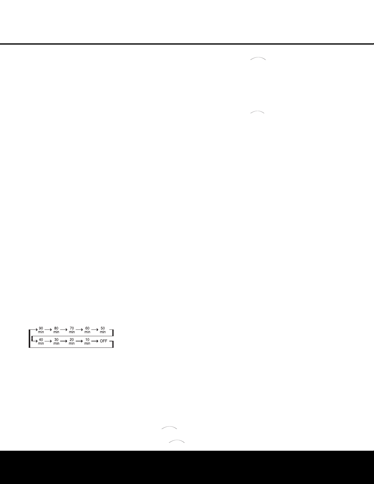
Basic Operation
Once you have completed the initial setup and configu-
r
ation of the AVR 240, it is simple to operate and
e
njoy. The following instructions will help you maximize
the enjoyment of your new receiver:
Turning the AVR 240 On or Off
• When using the AVR 240 for the first time, you must
first press the
Main Power Switch
1
on the front
panel to turn the unit on. This places the unit in a
Standby mode, as indicated by the amber color of the
Power Indicator
2
. Once the unit is in Standby,
you may begin a listening session by pressing the
Standby/On Switch
3
on the front panel, or the
Power On Button d or AVR Selector f on the
remote. The
Power Indicator
2
will turn blue. This
will turn the unit on and return it to the input source that
was last used. The unit may also be turned on from
Standby by pressing any of the
Input Selector
Buttons
eg on the remote or the Input Source
Selector Button
^
on the front panel.
NOTE: After pressing one of the Input Selector
Buttons
eg to turn the unit on, press the AVR
Selector
f to set the remote control to the AVR 240
functions.
To turn the unit off at the end of a listening session,
simply press the
Standby/On Switch 3 on the front
panel or the
Power Off Button a on the remote.
Power will be shut off to any equipment plugged into
the rear-panel
Switched AC Accessory Outlet ›
and the Power Indicator 2 will turn amber.
When the remote is used to turn the unit “off” it is
actually placing the system in a Standby mode, as indi-
cated by the amber color of the
Po
wer Indicator
2.
• To program the AVR 240 for automatic turn-off,
press the
Sleep Button j on the remote. Each
press of the button will decrease the time before
shut-down in the following sequence:
The sleep time will be displayed in the
Lo
wer
Display Line
Q.
The front-panel display will dim
to one-half brightness when the Sleep function is
programmed.
To view the current sleep time when
the sleep function has been activated,
press the
Sleep Button j
once. The display will return to
normal brightness, and the time until shutdown will
appear in the
Lower Display Line ı
.
After a few
seconds, the message will disappear and the dis-
play will retur
n to half-brightness
.
•
When the programmed sleep time has elapsed, the
unit will automatically turn off. To cancel the Sleep
function,
press and hold the
Sleep Buttonj as
t
he information display returns to normal brightness;
c
ontinue to hold the button until the Sleep indicator
numbers disappear and the words
SLEEP
OFF
appear in the Lower Display Line Q
.
W
hen you will be away from home for an extended
period of time it is always a good idea to completely
turn the unit off with the front-panel
Main Power
Switch
1
.
N
OTE:
A
ll preset memories are lost if the unit is left
turned off by using the
Main Power Switch
1
for
more than four weeks.
Source Selection
• To select a source, press any of the Input
Selector
Buttons
egde on the
remote.
• The input source may also be changed by pressing
the front-panel
Input Source Selector Button ^.
Each press of the button will move the input selec-
tion through the list of available inputs.
• As the input is changed, the AVR 240 will auto-
matically switch to the digital input (if selected),
component video input, surround mode, output
levels and night mode status as well as any speaker
configuration settings established by using the
INDEPENDENT Bass Management setting,
that were entered during the configuration process
for that source.
• When the input source is changed, the new input
name and the digital (or analog) audio input will
appear in the
Upper Display Line P, and the
current surround mode will appear in the
Lower
Display Line
ı. The same messages will also
appear momentarily in the on-screen display in the
lower third of the screen (semi-OSD).
• When an audio source is selected, the last video
input used remains routed to the
Video 1 Video and
S-Video Outputs
hY
and Component Video,
Composite Video
and S-Video Monitor Outputs
‹cV.
This per
mits you to simultaneously view
and listen to different sources. This also allows you
to choose a video source and then select the
6/8-
Channel Direct Inputs
j
as the audio source
.
•
The front-panel
Video 4 Inputs ÓÔ, Optical 3
Digital Input
*
or the Coaxial 3 Digital Input
(
may be used to connect a device such as a video
game or camcorder to your home entertainment
system on a temporary basis.
• When DMP is selected as the source
and a compatible iPod is inserted in an optional
Har
man Kardon
that is connected to
DMP Connector e on the rear panel,
n
avigation messages will appear on any video
d
isplay connected to the AVR’s
V
ideo Monitor
Outputs
cV. The remote control or front-panel
controls may be used to navigate the iPod and
access many of its functions. These messages will
a
lso appear in the front-panel display, and the iPod’s
battery may be charged. See the owner’s guides for
and your iPod for more information.
6-Channel/8-Channel Direct Input
• There are two input choices available for use with
sources such as a DVD-Audio or SACD player that
are connected to the
6/8-Channel Direct Inputs
j.
Select the appropriate input according to
the way your system and source equipment are
configured:
n 6 CH DIRECT should be used when
the SBR and SBL inputs are NOT in use. It is
assumed that the input source device has its own
internal bass management system. This input
passes the input from the source directly through
to the volume control without any analog to digital
conversion and it mutes the unused input jacks to
prevent unwanted noise from interfering with sys-
tem performance.
n 8 CH DIRECT should be used when an
input is connected to all eight
8-Channel Direct
Inputs
j. It is assumed that the input source
device has its own internal bass management
system. This input passes the input from the
source directly through to the volume control
without any analog-to-digital conversion and it
mutes the unused input jacks to prevent unwanted
noise from interfering with system performance.
Volume Control
• Adjust the volume to a comfortable level using the
front-panel
Volume Control Ò or remote Volume
Up/Down Buttons
b.
• To temporarily silence all speaker outputs, press
the
Mute Button f. This will interrupt the output
to all speakers and the headphone jack,
but it will
not affect any recording or dubbing that may be
in progress. When the system is muted, the word
MUTE will flash in the Upper Display Line P.
Press the
Mute Button f again to return to
nor
mal operation.
• You may adjust the bass and treble tone controls
at any point during a listening session by pressing
the
Tone Mode Button 5 until TONE IN
appears in the Lower Display Line ı. Press
the
Tone Mode Button 5 again until either
TREBLE
MODE
or BASS
MODE
The
Bridge
TM
The
Bridge
TM
The
Bridge
TM
The
Bridge
TM
OPERATION
OPERATION 31

32 OPERATION
OPERATION
appears in the Lower Display Line 5, and then
u
se the
‹/› B
uttons
) t
o boost or cut the low
or high frequencies by up to ±10dB, in 2dB steps,
until the desired setting is achieved. You may also
totally remove the tone controls from the circuit so
t
hat the output is “flat” at any time by pressing the
T
one Mode Button
5 a
nd then pressing the
‹/›
Buttons ) so that TONE OUT appears
in the on-screen display and the
Lower Display
Line
ı. The tone controls may also be adjusted
u
sing the
A
UDIO SETUP
s
ubmenu as
described on page 21.
• For private listening, plug the 1/4" stereo phone
plug from a pair of stereo headphones into the
front-panel
Headphone Jack
4
. When the
headphone plug is connected, all speakers will be
silenced and
DOLBY H:BP will scroll once
across the
Lower Display Line ı , indicating that
the headphone output is in the Bypass mode, and
to confirm that no processing is being used. When
the headphone plug is removed, the audio feed to
the speakers will be restored.
• When the headphones are in use, you may take
advantage of the Dolby Headphone modes to bring
added spaciousness to headphone listening. Press
the
Dolby Mode Select Button w or the
Surround Mode Group Selector 7 to cycle
through the three Dolby Headphone modes and
select the one that you prefer.
Surround Mode Selection
One of the important features of the AVR 240 is its
ability to reproduce a full multichannel surround sound
field from digital sources, analog matrix surround-
encoded programs and standard stereo programs.
Selection of a surround mode is based on personal
taste, as well as the type of program source material
being used. For example, motion pictures or TV pro-
grams bearing the logo of one of the major surround-
encoding processes, such as Dolby Surround or DTS
Stereo
, may be played in either the Dolby Digital, Dolby
Pro Logic II or IIx Movie,
DTS Neo:6 Cinema,
or
Logic 7 5.1 or 7.1 Cinema surround modes.
NOTE: Once a program has been encoded with matrix
surround information, it retains the surround information
as long as the program is broadcast in stereo. Thus,
movies with surround sound may be decoded via any of
the analog surround modes such as Dolby Pro Logic IIx
Cinema, Logic 7 Cinema or DTS Neo:6 Cinema, when
they are broadcast via conventional TV stations, cable,
pay-TV and satellite transmission.
In addition,
a growing
number of made-for-television programs, sports broad-
casts
,
radio dramas and music CDs are also recorded
in surround sound.
E
ven when a program is not listed as carrying inten-
t
ional surround information, you may find that the Dolby
Pro Logic IIx, Logic 7 Enhanced or DTS Neo:6, VMAx
and the Hall or Theater modes often deliver enveloping
surround presentations through the use of the natural
i
nformation present in all stereo recordings.
S
urround modes may be changed at any time by
using either the front panel or remote control. Any
changes made to the surround mode for that source
will be retained in the AVR’s menu, even after another
source is selected, or if the AVR is placed in Standby
mode. To select a new surround mode from the
front panel, first press the
Surround Mode Group
Selector Button
7 until the desired major surround
mode group, such as Dolby, DTS or Logic 7, is select-
ed. Next, press the
Surround Mode Selector Button
8 to choose the specific individual surround mode.
To select a surround mode using the remote, press
the button for the major surround mode group that
includes the mode you wish to choose from:
Dolby
w, DTS Surround x, DTS Neo:6 S,
Logic 7 y, Stereo R or DSP Surround k.
The first press of the button will show the current
mode from that group. To cycle through the available
modes in that group, press the button again until the
desired mode appears in the
Lower Display Line
ı, the on-screen display and in the Surround
Mode Indicators
ˆ. As the surround mode
changes, the appropriate
Surround Mode Indicator
ˆ will light to indicate the current mode. At times, it
is possible that more than one indicator will light. This
can occur when the DSP Surround Off mode has
been selected, or when post-processing is being used
with an input signal, such as when the Dolby Digital
2.0 plus Dolby Pro Logic IIx mode is used to create
a 7-channel presentation of a two-channel signal.
The Dolby Digital, Dolby Digital EX and DTS 5.1,
DTS-ES Matrix and DTS-ES Discrete modes may only
be selected when a digital input is in use and a digital
signal in that format is present. In addition, when a
digital source is present, the AVR 240 will automatically
select and switch to the correct mode, regardless of
the mode that has been previously selected. For more
information on selecting digital sources, see the Digital
Audio Playback section.
The Dolby Pro Logic IIx modes are available only
when the AVR 240 has been configured for 6.1/7.1
operation by setting the Surround Back speakers as
either
LARGE or SMALL as described on page
26. These modes provide a matrixed 6.1-channel
presentation of analog sources
.
See page 26 for
more information.
When the 6-channel/8-channel direct inputs are in
use there is no surround processing, as these inputs
take the analog output signals from an optional,
exter
-
n
al DVD-Audio or SACD player, or another source
d
evice and carry them straight through to the volume
control without any further digital processing.
To listen to a program in traditional two-channel stereo,
using the front left and front right speakers only (plus
the subwoofer, if installed and configured), press the
S
tereo Button
R
u
ntil
S
URROUND OFF
appears in the Lower Display Line
ı
, or press the
Surround Mode Group Selector 7 until the Stereo
modes appear in the on-screen display and Lower
Display Line
ı
and then press the Surround Mode
Select Button
8 until SURROUND OFF
appears in the on-screen display and Lower Display
Line
ı
.
When an analog audio source is in use, you may
activate an analog bypass Surround Off mode, if you
have removed the tone controls from the processing
circuitry by pressing the
Tone Mode Button 5
and using the ‹/› Buttons )o until the
TONE OUT message appears in the Lower
Display Line
ı.
Normally, the DSP icon will appear in the
Surround Mode Indicators ˆ, and the message
SURROUND OFF will appear in the lower line
of the semi-OSD display. When the DSP icon appears,
the incoming signal is digitized and any bass manage-
ment settings are applied. This mode is recommended
when your front speakers are not capable of repro-
ducing the lower frequencies and are thus used with
a subwoofer.
When the DSP icon is not lit in Surround Off mode
with an analog audio input in use, the AVR is in analog
bypass mode. The signal is being routed directly to the
volume control, without entering the digital domain and
without any bass management settings being applied.
This mode is desirable when your left and right speak-
ers are capable of reproducing low frequencies
, and
when you wish to hear the analog source material in
its pure form.
Digital
Audio Playback
Digital audio is a major advancement over older analog
surround processing systems such as Dolby Pro Logic.
It delivers five
,
six or seven discrete channels: left front,
center
, right front, left surround, right surround and
optionally one or two surround back channels. Each
channel reproduces full frequency range (20Hz to
20kHz) and offers dramatically improved dynamic range
and significant improvements to signal-to-noise ratios
.
In
addition, digital systems have the capability to deliver an
additional channel that is specifically devoted to low-fre-
quency information. This is the “.1” channel referred to
when you see these systems described as
“5.1
,
”
“6.1”
or “7.1”. The bass channel is separate from the other
channels, but since it is intentionally bandwidth-limited,
sound designers have given it that unique designation.
OPERATION

OPERATION
Surround Mode Chart
MODE FEATURES
D
olby Digital Available only with digital input sources encoded with Dolby Digital data. It provides up to five separate main audio channels and a special
dedicated Low-Frequency Effects channel.
Dolby Digital EX Available when the receiver is configured for 6.1/7.1-channel operation, Dolby Digital EX is the latest version of Dolby Digital. When used
with movies or other programs that have special encoding, Dolby Digital EX reproduces specially encoded soundtracks so that a full 6.1/7.1
s
ound field is available. When the receiver is set for 6.1/7.1 operation and a Dolby Digital signal is present, the EX mode is automatically
selected. Even if specific EX encoding is not available to provide the additional channel, EX mode may be manually selected to derive
a 6.1/7.1 output.
DTS 5.1 When the speaker configuration is set for 5.1-channel operation, the DTS 5.1 mode is available when DVD, audio-only music or laser discs
encoded with DTS data are played. DTS 5.1 provides up to five separate main audio channels and a special dedicated low-frequency channel.
DTS-ES 6.1 Matrix When the speaker configuration is set for 6.1/7.1 operation, newer discs with special DTS-ES discrete or Matrix encoding will be decoded
DTS-ES 6.1 Discrete to provide six discrete, full-bandwidth channels plus a separate low-frequency channel.
Dolby Pro Logic II Dolby Pro Logic II decodes full-range discrete left, center, right, right surround and left surround channels from either matrix surround-encoded
Movie programs and conventional stereo sources when an analog input is in use. The Dolby Pro Logic II Movie mode is optimized for movie soundtracks,
Music while the Pro Logic II Music mode should be used with musical selections. Game mode ensures that special effects are routed to the surround
Game channels, while delivering their full impact using the subwoofer, thus fully immersing the player in the universe of the video game.
Pro Logic The Pro Logic mode activates original Pro Logic processing for those who prefer that presentation.
Dolby Pro Logic IIx
Dolby Pro Logic IIx is the latest extension of Dolby Pro Logic II technology that creates a discrete 6.1 and 7.1 sound field from matrix surround
Music
or two-channel stereo sources in systems configured for surround back speakers. Movie, Music and Game versions of Pro Logic IIx are available.
Movie
Game mode ensures that special effects are routed to the surround channels, while delivering their full impact using the subwoofer, thus fully
Game
immersing the player in the universe of the video game. Dolby Pro Logic IIx post processing may be available with some DTS digital sources,
depending on the number of channels present in the input signal, to provide a 6.1-channel presentation in movie or music mode.
Logic 7 Cinema Exclusive to Harman Kardon for A/V receivers, Logic 7 is an advanced mode that extracts the maximum surround information
Logic 7 Music from either surround-encoded programs or conventional stereo material. Depending on the number of speakers in use
Logic 7 Enhance and the selection made in the
SURROUND SELECT menu, the “5.1” versions of Logic 7 modes are available
when the 5.1 option is chosen, while the “7.1” versions of Logic 7 produce a full sound field presentation, including back surround
speakers when the “6.1/7.1” option is chosen. The Logic 7 Cinema mode should be used with any source that contains
Dolby Surround or similar matrix encoding. Logic 7 Cinema delivers increased center-channel intelligibility, and more accurate placement of
sounds with fades and pans that are much smoother and more realistic than with other decoding techniques. The Logic 7 Music mode
should be used with analog or PCM stereo sources. Logic 7 Music enhances the listening experience by presenting a wider front soundstage
and greater rear ambience
.
Both Logic 7 modes also direct low-frequency information to the subwoofer (if installed and configured)
to deliver maximum bass impact. The Logic 7 Enhance mode is an extension of the Logic 7 mode that is primarily used with musical programs.
Logic 7 Enhance adds additional bass enhancement that circulates low frequencies in the 40Hz to 120Hz range to the front and surround
speakers to deliver a less localized soundstage that appears broader and wider than when the subwoofer is the sole source of bass energy.
DTS Neo:6 Cinema These two modes are available when any analog or DTS Digital source is playing to create a six-channel surround presentation from conventional
DTS Neo:6 Music
Matrix-encoded and traditional Stereo sources.
Select the Cinema version of Neo:6 when a program with any type of analog Matrix surround
encoding is present. Select the Music version of Neo:6 for optimal processing when a nonencoded,
two-channel stereo program is being played.
When selecting a DTS Neo:6 Cinema mode
, a 3-, 5- or 6-channel configuration may be available, depending on the number of speakers
in your system. Use 3-channel mode when only a front left and right and a center speaker are present; surround-channel information
will be mixed into these speakers. The 6-channel mode will only be available if you have configured your surround back speakers as active.
DTS 96/24 DTS 96/24 is a high-resolution format that uses a 96kHz sampling rate with 24 bits to produce extended information that improves
the harmonics of the source material.
The
A
VR is capable of automatically detecting and decoding DTS 96/24 materials and delivering them
as the artist intended.
Dolby 3 Stereo
Uses the infor
mation contained in a two-channel analog or PCM (44.1 or 48kHz) program,
or with the tuner, to create center-channel information.
In addition,
the information that is normally sent to the rear-channel surround speakers is carefully mixed in with the front-left and front-right
channels for increased realism. Use this mode when you have a center channel speaker but no surround speakers.
OPERATION 33

34 OPERATION
OPERATION
D
olby Virtual Speaker Dolby Virtual Speaker uses advanced technology to simulate the sonic signature of a speaker location even when there is no speaker physically
Reference present in that location. The Reference (“REF”) mode activates any missing speakers to simulate a 5.1 presentation with accurate localization.
Wide The Wide mode virtualizes the locations of the front-channel speakers to create a wider image and a more enveloping sound field. Dolby Virtual
Speaker – Reference is available for use with two or three actual speakers, and Dolby Virtual Speaker – Wide may be used with systems
c
onsisting of two, three, four or five speakers (not including the subwoofer). The specific mode available will vary depending on the
number of channels in the incoming Dolby Digital signal.
Theater The Theater mode creates a sound field that resembles the acoustic feeling of a standard live-performance theater. Depending on
whether you have configured your surround back speakers as active, 5-channel or 6-channel versions of this mode may be available.
Hall 1, Hall 2 The two Hall modes create sound fields that resemble a small (Hall 1) and medium-sized (Hall 2) concert hall. Depending on whether
y
ou have configured your surround back speakers as active, 5-channel or 6-channel versions of this mode may be available.
VMAx Near When only the two front-channel loudspeakers are used, Harman’s patented VMAx mode delivers a three-dimensional sound space
VMAx Far with the illusion of “phantom speakers” at the center and surround positions. The VMAx Near Field mode should be selected when
your listening position is less than five feet from the speakers. The VMAx Far Field mode should be selected when your listening
position is greater than five feet from the speakers.
5-Channel Stereo This mode takes advantage of multiple speakers to place a stereo signal at both the front and back of a room. Depending on whether
7-Channel Stereo the AVR has been configured for either 5.1 or 6.1/7.1 operation, one of these modes is available at any time. Ideal for playing music
in situations such as a party, it places the same signal at the front-left and surround-left, and front-right and surround-right speakers.
The center channel is fed a summed mono mix of the in-phase material of the left and right channels.
Surround Off This mode turns off all surround processing and presents the pure left- and right-channel presentation of two-channel stereo programs.
(Stereo) When used with an analog audio source, you may select between a digitized Surround Off mode, in which the incoming signal is digitized
and any bass management settings are applied, or an analog bypass Surround Off mode, in which the incoming signal is passed directly to
the volume control and a full-range signal is sent to your left and right main speakers.
Dolby Headphone Dolby Headphone enables ordinary stereo headphones to portray the sound of a five-speaker surround-playback system. The DH1
DH1 mode creates a headphone presentation that resembles a small, well-damped room and is appropriate for use with both movies and
DH2 music-only recordings. The DH2 mode creates a more acoustically live room particularly suited to music listening. The DH3 mode creates a
DH3 larger room, more like a concert hall or movie theater. The Bypass mode sends a “pure stereo” feed to the headphones.
For additional information on the specifics of surround modes and processing, information about Dolby modes may be found at www.dolby.com. Information about DTS modes
is available at www.dtsonline.com.

D
olby Digital
D
olby Digital is a standard part of DVD, and is available
on specially encoded LD discs and satellite broadcasts
and it is a part of the high-definition television (HDTV)
system.
An optional, external RF demodulator is required to
u
se the AVR 240 to listen to the Dolby Digital sound-
tracks available on laser discs. Connect the RF output
of the LD player to the demodulator and then connect
the digital output of the demodulator to the
Optical or
Coaxial Inputs *(bg of the AVR 240. No
demodulator is required for use with DVD players or
DTS-encoded laser discs.
DTS
DTS is another digital audio system that is capable of
delivering 5.1 or 6.1 discrete or matrix sound field
reproduction. Although both DTS and Dolby Digital are
digital, they use different methods of encoding the sig-
nals, and thus they require different decoding circuits
to convert the digital signals back to analog.
DTS-encoded soundtracks are available on select DVD
and LD discs, as well as on special audio-only DTS
discs. You may use any LD or CD player equipped
with a digital output to play DTS-encoded discs with
the AVR 240. All that is required is to connect the
player’s output to either an
Optical or Coaxial Input
on the rear panel bg or front panel *(.
In order to listen to DVDs encoded with DTS sound-
tracks, the DVD player must be compatible with the
DTS signal as indicated by a DTS logo on the player’s
front panel. Early DVD players may not be able to play
DTS-encoded DVDs. This does not indicate a problem
with the AVR 240, as some players cannot pass the
DTS signal through to the digital outputs. If you are in
doubt as to the capability of your DVD player to handle
DTS discs, consult the player’s owner’s manual.
IMPOR
TANT NOTE:
Many DVD players have a default
setting that does not pass through the DTS data, even
though the machine is capable of doing so. If your
DVD player has the “DTS Digital Out” logo but does
not trigger DTS playback in the
AVR 240, change the
player's settings in the “Audio” or “Bitstream” configu-
ration menu so that DTS playback is enabled. The
method for doing this will vary with each player. In
some cases,
the proper menu choice will be
“Original,”
while in others it will be “DTS.” Consult the owner's
manual for your player to find the specific information
to find the proper setting.
Selecting a Digital Source
T
o utilize either digital mode,
you must have properly
connected a digital source to the AVR 240. Connect
the digital outputs from DVD players, HDTV receivers,
satellite systems or CD players to the
Optical or
Coaxial Inputs *(bg. In order to provide a
backup signal and a source for analog stereo recording
,
the analog outputs provided on digital source equipment
s
hould also be connected to their appropriate inputs on
t
he AVR 240 rear panel (e.g., connect the analog stereo
audio output from a DVD to the
DVD Audio Inputs W
on the rear panel when you connect the source’s
digital outputs).
If you have not already configured an input for a digital
source using the on-screen menus as shown on page
20, first select the input using the remote or front-
panel controls as outlined in this manual. Next, select
the digital source by pressing the
Digital Select
Button
q# and then using the
⁄
/
¤
Buttons
n on the remote or the
‹
/
›
Selector Buttons
) on the front panel to
choose any of the
OPTICAL or COAXIAL
inputs, as they
appear in the
Upper Display Line P or on-screen
display. When the digital source is playing, the
A
VR 240 will automatically detect which type of digital
data stream is being decoded and display that infor-
mation in the Upper Display Line P.
Digital Bitstream Indications
When a digital source is playing, the AVR 240 senses
the type of bitstream data that is present. Using this
information, the correct surround mode will automati-
cally be selected. For example, DTS bitstreams will
cause the unit to switch to DTS decoding, and Dolby
Digital bitstreams will enable Dolby Digital decoding.
When the unit senses PCM data from CDs or LDs,
it will default to Logic 7 Music mode, although you
may select any of the standard surround modes, such
as Dolby Pro Logic II or Logic 7. Since the range of
available surround modes is dependent on the type of
digital data that is present, the AVR 240 uses a variety
of indicators and messages to let you know what type
of signal is present. These messages will appear shortly
after an input or surround mode is changed,
and they
will remain in the
Lower Display Line ı for about
five seconds before that portion of the display returns
to the normal surround mode indication.
Surround Mode Channel Indications
For Dolby Digital and DTS sources, a three-digit indi-
cation will appear
,
showing the number of channels
present in the data. An example of this type of display
is
3/2/.1.
The first number indicates how many discrete front
channel signals are present.
• A “3” tells you that separate front left, center and
front right signals are available. This will be displayed
for Dolby Digital 5.1 and DTS 5.1 programs.
•
A
“2” tells you that separate front left and right
signals are available, but there is no discrete center
channel signal. This will be displayed for Dolby
Digital bitstreams that have stereo program
material.
• A “1” tells you that there is only a mono channel
available in the Dolby Digital bitstream.
T
he middle number indicates how many discrete sur-
r
ound channel signals are present.
•
A “2” tells you that separate surround left and right
signals are available. This will be displayed for Dolby
Digital 5.1 and DTS 5.1 programs.
•
A “1” tells you that there is only a single, surround-
encoded surround channel. This will appear for
Dolby Digital bitstreams that have matrix encoding.
• A “0” indicates that there is no surround channel
i
nformation. This will be displayed for two-channel
stereo programs.
The last number indicates whether there is a discrete
low-frequency effects (LFE) channel. This is the “.1”
in the common abbreviation of “5.1” sound and is a
special channel that contains only bass frequencies.
•
A “1” tells you that an LFE channel is present.
This will be displayed for Dolby Digital 5.1 and
DTS 5.1 programs, as available.
• A “0” indicates that there is no LFE channel infor-
mation available. However, even when there is no
dedicated LFE channel, low-frequency sound will
be present at the subwoofer output when the
speaker configuration is set to show the presence
of a subwoofer.
The information in the right side of the display will
tell you if the digital audio data contains a special flag
signal that will automatically activate the appropriate
6.1 or 7.1 mode. This will be shown as
EX-ON
or EX-OFF for Dolby Digital bitstreams and
ES-ON or ES-OFF for DTS bitstreams.
If the EX flag is off, and your receiver has been config-
ured for 6.1/7.1 operation, you may manually turn on
EX processing as appropriate by simply selecting the
Dolby Digital EX surround mode as described on
pages 21 and 32. When the ES flag is not present in
a DTS bitstream, you may benefit from a 6.1-channel
presentation by selecting the DTS+Neo:6 post-pro
-
cessing surround mode using the procedure described
on pages 21 and 32. In that mode, the DTS Neo:6
algorithms will be used to derive the surround back
channel from the DTS bitstream information.
When Dolby Digital 3/2/.1 or DTS 3/2/.1 signals are
being played, the AVR will automatically switch to the
proper surround mode, and no other processing may
be selected,
with these exceptions:
•
When a Dolby Digital 2.0 signal is detected,
you
may choose to listen to it in its native form. To do
so, scroll through the Dolby surround modes until
the Stereo icon lights in the
Surround Mode
Indicators
ˆ in addition to the Dolby Digital icon.
Alter
natively
,
you may engage surround post-pro-
cessing by scrolling through the Dolby Pro Logic II
and IIx modes, and the Dolby Pro Logic icon will
light in addition to the Dolby Digital icon.
OPERATION
OPERATION 35
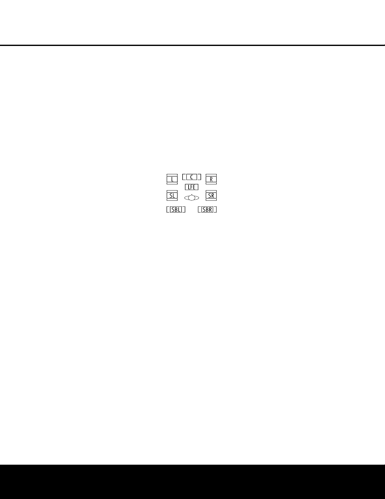
•
As indicated above, when the EX flag is not present
i
n a Dolby Digital bitstream, you may scroll through
the Dolby surround modes to manually select Dolby
Digital EX processing.
•
When a DTS 5.1 signal is detected, you may listen
to it as a two-channel presentation, a 5.1-channel
presentation or a 6.1-channel presentation (if your
AVR is configured for 6.1/7.1 operation). To hear a
two-channel presentation, scroll through the DTS
surround modes until the Stereo icon lights in the
Surround Mode Indicators ˆ in addition to the
DTS icon. Continue scrolling to engage DTS 5.1
processing or DTS+Neo:6 (6-channel) processing.
• If a DTS-ES 6.1 Discrete signal is present, you may
choose a two-channel presentation, a 5.1-channel
presentation or a 6.1-channel presentation (if your
AVR has been configured for 6.1/7.1 operation).
Scroll through the DTS surround modes until the
Stereo icon lights in the
Surround Mode
Indicators
ˆ, in addition to the DTS icon.
Continue scrolling to engage DTS 5.1 processing
or DTS-ES Discrete processing.
When a Dolby Digital signal with a 3/1/0 or 2/0/0
signal is detected you may select any of the Dolby
surround modes.
See page 40 for information on setting a default sur-
round mode.
It is always a good idea to check the readout for the
channel data to make certain that it matches the audio
logo information shown on the back of a DVD pack-
age. In some cases you will see indication for “2/0/0”
even when the disc contains a full 5.1, or 3/2/.1 sig-
nal. When this happens, check the audio output set-
tings for your DVD player or the audio menu selections
for the specific disc being played to make certain that
the player is sending the correct signal to the
A
VR.
PCM
Audio Playback
PCM is the abbreviation for Pulse Code Modulation,
which is the type of digital signal used for standard CD
playback and other non-Dolby Digital and non-DTS
digital sources such as Mini-Disc
.
The digital circuits
in the AVR 240 are capable of high-quality digital-to-
analog decoding, and they may be connected directly
to the digital audio output of your CD or LD player.
Connections may be made to either the rear-panel
Optical or Coaxial Inputs bg or the front-panel
Digital Inputs *(.
To listen to a PCM digital source, first select the input for
the desired source (e.g., CD). Next press the
Digital
Select
Button
#
q
and then use the
⁄
/
¤
Buttons n on the remote, or the
‹
/
›
Selector
Buttons
) on the front panel,
until the desired choice
appears in the
Upper Display Line P.
D
uring PCM playback, you may select any Surround
m
ode except Dolby Digital or DTS.
When a PCM signal is detected, the
Lower Display
L
ine
ı w
ill briefly show a message with the letters
PCM, in addition to a readout of the sampling fre-
quency of the digital signal. In most cases this will be
48kHz, though in the case of specially mastered,
high-resolution audio discs you will see a
96kHz
i
ndication.
Speaker/Channel Indicators
In addition to the bitstream indicators, the AVR 240
features a set of unique channel-input indicators that
tell you how many channels of digital information are
being received and/or whether the digital signal is
interrupted. (See Figure 16.)
Figure 16
These indicators are the L/C/R/LFE/SL/SR/SBL/SBR
letters that are inside the center boxes of the
Speaker/
Channel Input Indicators
O on the front panel.
When a standard analog signal is in use, only the “L”
and “R” indicators will light, as
analog signals have
only left and right channels.
Digital signals, however, may have two, five, six or
seven channels, depending on the program material,
the method of transmission and the way in which it
was encoded. When a digital signal is playing, the let-
ters in these indicators will light in response to the
specific signal being received.
It is important to note
that although Dolby Digital, for example, is referred to
as a “5.1” system, not all Dolby Digital DVDs or pro-
grams are encoded for 5.1. Thus, it is sometimes nor-
mal for a DVD with a Dolby Digital soundtrack to trig
-
ger only the “L” and “R” indicators.
NOTE: Many DVD discs are recorded with both “5.1”
and “2.0” versions of the same soundtrack. When
playing a DVD, always be certain to check the type of
material on the disc
. Most discs show this information
in the form of a listing or icon on the back of the disc
jacket. When a disc does offer multiple soundtrack
choices, you may have to make some adjustments to
your DVD player (usually with the
“
Audio Select”
button
or in a menu screen on the disc) to send a full 5.1
feed to the AVR 240. It is also possible for the type
of signal feed to change during the course of a DVD
playback.
In some cases
,
the menu screens and pre
-
views of special material will only be recorded in 2.0
audio, while the main feature is available in 5.1 audio.
The
AVR 240 will automatically sense changes to the
b
itstream and channel count and reflect them in these
i
ndicators.
The letters used by the
Speaker/Channel Input
I
ndicators
O a
lso flash to indicate when a bitstream
has been interrupted. This will happen when a digital
input source is selected before the playback starts, or
when a digital source such as a DVD is paused. The
flashing indicators remind you that the playback has
s
topped due to the absence of a digital signal and not
through any fault of the AVR 240. This is normal, and
the digital playback will resume once the playback is
started again.
Night Mode
A special feature of Dolby Digital is the Night mode,
which enables specially encoded Dolby Digital input
sources to be played back with full digital intelligibility
while reducing the minimum peak level by 1/4 to 1/3.
This prevents abruptly loud transitions from disturbing
others, without reducing the impact of the digital
source. The Night mode is available only when Dolby
Digital signals with special data are being played.
The Night mode may be engaged when a Dolby
Digital DVD is playing by pressing the
Night Mode
Button
l on the remote. Next, press the
⁄
/
¤
Buttons n to select either the middle-range or
full-compression versions of the Night mode. To turn
the Night mode off, press the
⁄
/
¤
Buttons n
until the message in the lower third of the video dis-
play and in the
Lower Display Line Q reads
D-RANGE OFF.
The Night mode may also be selected to always be on
at either level of compression using the options in the
DOLBY menu. See page 22 for information on
using the menus to set this option.
IMPORTANT NOTES ON DIGITAL PLAYBACK:
• When the digital playback source is stopped, or in
a pause,
fast-forward or chapter-search mode, the
digital audio data will momentarily stop, the channel
position letters inside the
Speaker/Channel Input
Indicators
O will flash. This is normal and does
not indicate a problem with either the
A
VR 240 or
the source machine
. The AVR 240 will return to dig-
ital playback as soon as the data is available and
when the machine is in a standard play mode.
•
Although the
AVR 240 will decode virtually all current
DVD movies
,
CDs and HDTV sources
,
it is possible
that some future digital sources may not be compati-
ble with the AVR 240.
• Not all digitally encoded programs contain full 5.1-
or 6.1-channel audio
.
Consult the program guide
that accompanies the DVD or laser disc to deter-
mine which type of audio has been recorded on the
disc
. The AVR 240 will automatically sense the type
OPERATION
36 OPERATION

OPERATION
OPERATION 37OPERATION 37
o
f digital surround encoding used and adjust to
a
ccommodate it.
• When some digital sources are playing, you may
not be able to select some of the analog surround
m
odes such as Dolby Pro Logic II or IIx, Dolby 3
Stereo, Hall, Theater or Logic 7.
• When a Dolby Digital or DTS source is playing, it is
not possible to make an analog recording using the
T
ape Outputs
£ a
nd
V
ideo 1 Audio Outputs
Y. However, the digital signals will be passed
through to the
Digital Audio Outputs ·a.
Tuner Operation
The AVR 240’s tuner is capable of tuning AM, FM and
FM Stereo broadcast stations. Stations may be tuned
manually
, or they may be stored as favorite station
presets and recalled from a 30-position memory.
Station Selection
1. Press the AM/FM Tuner Select Button g on
the remote to select the tuner as an input. The
tuner may be selected from the front panel either
by pressing the
Input Source Selector ^ until
the tuner is active or by pressing the
Tuner Band
Selector
!.
2. Press the
AM/FM Tuner Select Button g or
Tuner Band Selector ! again to switch between
AM and FM so that the desired frequency band is
selected.
3. Press the
Tuner Mode Button
&
I to select
manual or automatic tuning.
When the button is pressed so that
AUTO
appears in the Lower Display Line ı each
press of the
Tuning Selectors 9u will put
the tuner in a scan mode that seeks the next
higher- or lower-frequency station with acceptable
signal strength. An
AUTO ST TUNED indica-
tion
will momentarily appear when the station stops
at a stereo FM station, and an
AUTO TUNED
indication will momentarily appear when an AM or
monaural FM station is tuned.
Press the T
uning but-
tons again to scan to the next receivable station.
When the button is pressed so that
MANUAL
appears in the Lower Display Line ı each tap
of the Selector will increased or decrease the fre-
quency by one increment. When the tuner receives
a strong-enough signal for adequate reception,
MANUAL TUNED will appear in the Lower
Display Line
ı.
4. Stations may also be tuned directly in either the
automatic or manual mode
. To enter a station’s fre-
quency directly
,
first select the
AM or FM band as
desired be pressing the
AM/FM Tuner Select
Button
g. Next, press the Direct Button J.
W
ithin five seconds of seeing the
D
IRECT IN
scroll in the Upper Display Line P, enter the
station frequency by pressing the
Numeric Keys
r. If you press an incorrect button while entering
a
direct frequency, press the
C
lear Button
W t
o
s
tart over.
NOTE: When FM reception of a station is weak, audio
quality will be increased by switching to Mono mode
by pressing the
Tuner Mode Button
&
I so that
MANUAL appears momentarily in the Lower
Display Line
ı and goes out. This will also
activate manual tuning mode.
Preset Tuning
Using the remote, up to 30 stations may be stored in
the AVR 240’s memory for easy recall using the front
panel controls or the remote.
To enter a station into the memory, first tune the
station using the steps outlined above. Then:
1. Press the
Memory Button X on the remote.
Two underscore lines will appear at the far right
side of the
Upper Display Line P.
2. Within five seconds, press the
Numeric Keys r
corresponding to the location where you wish to
store this station’s frequency. Once entered, the
preset number will appear in the
Upper Display
Line
P.
3. Repeat the process after tuning any additional
stations to be preset.
Recalling Preset Stations
• To manually select a station previously entered in
the preset memory, press the
Numeric Keys r
that correspond to the desired station’s memory
location.
• To manually tune through the list of stored preset
stations one by one,
press the
Preset
Stations
Selector Buttons
$T on the front panel or
remote.
Recording
In nor
mal operation, the audio or video source
selected for listening through the
A
VR 240 is sent to
the record outputs. This means that any program you
are watching or listening to may be recorded simply
by placing machines connected to the
T
a
pe Outputs
£ or Video 1 Audio/Video and S-Video Outputs
hY in the Record mode
.
When a digital audio recorder is connected to the
Digital Audio Outputs ·a, you are able to record
the digital signal using a CD-R
,
MiniDisc or other digital
recording system.
N
OTES:
•
The digital outputs are active only when a digital sig-
nal is present, and they do not convert an analog
input to a digital signal, or change the format of the
digital signal. In addition, the digital recorder must
b
e compatible with the output signal. For example,
the PCM digital input from a CD player may be
recorded on a CD-R or MiniDisc, but Dolby Digital
or DTS signals may not.
• Please make certain that you are aware of any
copyright restrictions on any material you copy.
Unauthorized duplication of copyrighted materials
is prohibited by federal law.
Using
When Harman Kardon’s (optional) is connected
and a compatible iPod
®
is docked in The Bridge, press
the
DMP Selector Button d to choose
the iPod as the input source. Pressing the
DMP
Selector Button
d will also activate the
AVR remote’s control codes for the iPod, and you may
also use the front-panel controls to operate the iPod.
You may also select DMP as the source
from the front panel by repeatedly pressing the
Input
Source Selector
^ until DMP appears in the
Upper Display Line P, although no Input
Indicator
Ú will light.
When The Bridge is properly connected and a com-
patible iPod is properly docked,
DMP/THE
BRIDGE IS CONNECTED
will scroll
across the
Upper Display Line P. Once that mes-
sage appears, use the remote or front-panel buttons
to control the iPod. See the Function List Table on
pages 44–45 for a listing of the remote control but-
tons that have been programmed to control the iPod.
In brief, the
Reverse Search, Play and Forward
Search Buttons
` and the ⁄/¤/‹/›Buttons
no and Set Button p may be used in a sim-
ilar manner to the corresponding controls on the
iPod. Additional buttons on the remote may also be
used to navigate your iPod’s albums and playlists.
Complete details on operating an iP
od using
and an
AVR remote are furnished with .
The front-panel controls may be used to access a lim
-
ited number of iPod functions. Press the
Tuner Mode
Button
& to play or pause the current track.
The
T
uning Selector
9 may be used to search reverse
(left side of button) or forward (right side of button)
through the tracks. Press the
Tuner Band Selector
! to call up the iP
od’
s menu. Press the
Preset
Station Selectors
$ to scroll, and the Set Button
@ to select. For complete information on using the
AVR’s remote or front-panel controls to operate an
iPod, see the instructions packed with The Bridge.
The
Bridge
TM
The
Bridge
TM
The
Bridge
TM
The
Bridge
TM
The
Bridge
TM
The
Bridge
TM
The
Bridge
T
M

OPERATION
38
OPERATION
OPERATION
Output Level Trim Adjustment
Normal output level adjustment for the AVR 240 is
established using EzSet+, or the internal test tone, as
outlined on pages 29–30. In some cases, however, it
may be desirable to adjust the output levels using pro-
g
ram material such as a test disc, or a selection you
are familiar with.
T
o adjust the output levels using program material, first
s
et the reference volume for the front left and front right
channels using the Volume Control Òb
.
If you are using a disc with test signals or an external
signal generator as the source from which to trim the
output levels, you may use a handheld SPL meter to
guide you to the correct SPL levels. Set the meter to
the C-Weighting Slow scale, and adjust the volume
until the meter reads 75dB.
Once the reference level has been set, press the
Channel Select Button
m
and FRONT L
LEVEL
will appear in the Lower Display Line
Q and semi-OSD. To change the level, first press
the
Set Button p, and then use the
⁄
/
¤
Buttons
n
to raise or lower the level. DO NOT
use the volume control, as this will alter the
reference setting.
Once the change has been made, press the
Set
Button
p and then press the
⁄
/
¤
Buttons
n
to select the next output channel location you wish to
adjust. To adjust the subwoofer level, press the
⁄
/
¤
Buttons
n
until WOOFER LEVEL appears in
the
Lower Display Line Q and on screen.
Repeat the procedure as needed until all channels
requiring adjustment have been set. When all adjust-
ments have been made and no further adjustments
are made for five seconds, the AVR 240 will return to
nor
mal operation.
The channel output for any input may also be adjusted
using the full-OSD on-screen menu system. First, set
the volume to a comfortable listening level using the
Volume Control Òb. Then, press the OSD
Button
v to bring up the MASTER MENU
(Figure 1). Press the
¤
Button n until the on-
screen
›
cursor is next to the MANUAL
SETUP
line
.
Press the
Set Button p to display
the
MANUAL SETUP submenu, and use the
⁄/¤ Buttons n to scroll to the CHANNEL
ADJUST
line. Press the Set Button p again to
display the
CHANNEL ADJUST submenu.
Once the menu appears on your video screen,
first
use the
⁄
/
¤
Buttons n to move the on-screen
›
cursor so that it is next to the TEST TONE
line. Press the
‹
/
›
Buttons o so that OFF
appears
.
This will tur
n off the test tone and allow you
t
o use your external test disc or other source material
a
s the reference. Then, use the
⁄
/
¤
B
uttons
n
until the › cursor is next to the TEST TONE
SEQ
line so that you may select between automatic
and manual movement of the test tone from one
c
hannel to the next. When
A
UTO
a
ppears, the test
tone will automatically circulate from one channel to
the next, pausing momentarily at each channel. If you
adjust the level of any channel, the test tone will
r
emain paused at that channel until several seconds
a
fter your last adjustment before continuing to the next
channel. When
MANUAL appears, the test tone will
remain paused at the last channel until you use the
⁄/¤ Buttons n to select another channel.
At each channel position, use the
‹
/
›
Buttons o
to change the output level.
Remember, the goal is to
have the output level at each channel be equal when
heard at the listening position.
If you wish to reset all the levels to their original
factory default of 0dB offset, press the
⁄
/
¤
Buttons
n so that the on-screen cursor is next to the
CHANNEL RESET line and press the
‹
/
›
Buttons o so that the word ON appears.
After the
levels are reset, resume the procedure outlined above
to reset the levels to the desired settings. When all
adjustments are done, press the
⁄
/
¤
Buttons
n
to move the on-screen
›
cursor so that it is next to
BACK TO MANUAL SETUP and then press
the
Set Button p if you wish to go back to the
manual setup menu to make other adjustments. If you
have no other adjustments to make, press the
OSD
Button
v to exit the menu system.
NOTE: The output levels may be separately trimmed for
each digital and analog surround mode by selecting that
mode and following the instructions shown above.
Memory Backup
This product is equipped with a memor
y backup sys-
tem that preserves the system configuration information
and tuner presets if the unit is accidentally unplugged
or subjected to a power outage. This memory will last
for approximately four weeks,
after which time all infor-
mation must be reentered.

ADVANCED FEATURES
39
ADVANCED FEATURES
T
he AVR 240 is equipped with a number of advanced
f
eatures that add extra flexibility to the unit’s operation.
While it is not necessary to use these features to
operate the unit, they do provide additional options.
Figure 17
Front-Panel-Display Fade
In normal operation, the front-panel displays and indi-
cators remain on at full brightness, although you may
also dim them or turn them off using the
Dimmer
Button
h (see page 12). As an additional option,
you may also set the AVR so that the displays are on
whenever a button is pressed on the front panel or
remote, but then fade out after a set period of time.
To set the front-panel displays to the Fade mode,
press the
OSD Button v to bring the MASTER
MENU
(Figure 1) to the screen. Press the
⁄
/
¤
Buttons n so that the
›
cursor is pointed to the
ADVANCED line, and press the Set Button p
to enter the ADVANCED SELECT menu
(Figure 17).
With the
ADVANCED SELECT menu on
your video display, press the
⁄
/
¤
Buttons n so
that the
›
cursor is pointing to the VFD FADE
TIME OUT
line. Next, press the
‹
/
›
Buttons
o so that the amount of time that you wish the dis-
plays to fade out after a button is pressed is shown.
Select
OFF if you do not wish to have the front-
panel displays fade out.
Once this time is set and the unit returned to normal
operation, the displays will remain on for the time period
selected whenever a button is pressed on the front
panel or remote. After that time they will gradually fade
out, with the exception of the
Power Indicator 2,
which will remain on to remind you that the AVR is
turned on. Note that if the displays have been turned
completely off using the
Dim Button h, the Fade
function will not operate
.
If you wish to make adjustments to other items on
the
ADVANCED SELECT menu, press the
⁄
/
¤
Buttons n to place the
›
cursor next to
the desired item, or place the
›
cursor next to the
BACK
TO
MASTER
MENU
line and press
the Set Button p to make an adjustment to another
menu. If you have completed all adjustments, press
the
OSD Button v to exit the menu system.
T
urn-On Volume Level
A
s is the case with most audio/video receivers, when
the AVR 240 is turned on, it will always return to the
volume setting in effect when the unit was turned off.
However, you may prefer to always have the AVR 240
t
urn on at a specific setting, regardless of what was
last in use when the unit was turned off. To change
the default condition so that the same volume level
is always used at turn-on, you will need to make an
a
djustment in the
A
DVANCED SELECT
m
enu. To start the adjustment, press the
O
SD Button
v
to bring the MASTER MENU (Figure 1)
to the screen. Press the
¤
Button n, until the on-
screen
›
cursor is next to the ADVANCED line.
Press the Set Button p to enter the ADVANCED
SELECT
menu (Figure 17).
At the ADVANCED SELECT menu make
certain that the on-screen
›
cursor is next to the
VOLUME DEFAULT line by pressing the
⁄
/
¤
Buttons n as needed. Next, press the
›
Button o so that the word ON is shown in
the video display. Next, press the
¤
Button n
once so that the on-screen
›
cursor is next to the
DEFAULT VOL SET line. To set the desired
turn-on volume, press the
‹
/
›
Buttons o until the
desired volume level is shown on the
DEFAULT
VOL SET
line. This setting may NOT be made
with the regular volume controls.
NOTE: Since the setting for the turn-on volume
cannot be heard while the setting is being made, you
may wish to determine the setting before making the
adjustment. To do this, listen to any source and adjust
the volume to the desired level using the regular
Volume Controls Òb. When the desired volume
level to be used at turn-on is reached, make a note of
the setting as it appears in the lower third of the video
screen or in the
Lower Display Line ı. (A typical
volume level will appear as a negative number such as
–25dB.)
When making the adjustment, use the
‹
/
›
Buttons o to enter this setting.
The tur
n-on volume default will remain in effect until it
is changed or turned off in this menu, even when the
unit is turned off.
If you wish to make other adjustments, press the
⁄
/
¤
Buttons n until the on-screen
›
cursor
is next to the desired setting or the
BACK TO
MASTER MENU
line and press the Set Button
p. If you have no other adjustments to make, press
the
OSD
Button
v to exit the menu system.
Semi-OSD Settings
The semi-OSD system places one-line messages at
the lower third of the video display screen whenever
the Volume, Input Source, Surround mode, tuner
f
requency or any of the configuration settings are
c
hanged. The semi-OSD system is helpful in that it
provides feedback on any control changes or remote
commands using the video display when it is difficult
to view the front-panel displays. However, you may
o
ccasionally prefer to turn these displays off or adjust
the length of time the displays remain on the screen.
Both of those options are possible with the AVR 240.
This setting will also determine the length of time that
t
rack identification and play time messages will appear
o
n your video display when The Bridge is in use.
To change the length of time that the semi-OSD
displays remain on the screen, or to turn them off, go to
the
ADVANCED
SELECT menu as outlined
earlier, and press the
⁄
/
¤
Buttons n as needed,
until the on-screen
›
cursor is next to the SEMI
OSD TIME OUT
line. Next, press the
‹
/
›
Buttons o until the desired time in seconds or the
word
OFF is displayed. This is a permanent setting
change, and the time-out entry will remain in
effect
until it is changed, even when the unit is turned off.
If you wish to make other adjustments, press the
⁄
/
¤
Buttons n until the on-screen
›
cursor
is next to the desired setting or the
BACK TO
MASTER MENU
line and press the Set Button
p. If you have no other adjustments to make, press
the
OSD Button v to exit the menu system.
Full-OSD Time-Out Adjustment
The FULL OSD menu system is used to simplify
the setup and adjustment of the AVR 240, using a
series of on-screen menus. The factory default setting
for these menus leaves them on the screen for 20
seconds after a period of inactivity before they disap-
pear from the screen (Time-Out). Time-Out is a safety
measure to prevent image retention of the menu text
in your monitor or projector, which might happen if it
were left on indefinitely
. However, some viewers may
prefer a slightly longer or shorter period before the
Time-Out display.
T
o change the full-OSD
T
ime-Out,
you will need
to make an adjustment in the
ADVANCED
SELECT
menu (Figure 10). To start the adjust-
ment,
press the
OSD
Button
v to bring the
MASTER MENU to the screen. Press the ¤
Button n, until the on-screen › cursor is next to
the
ADVANCED line. Press the Set Button p
to enter the ADVANCED menu (Figure 17).
At the
ADVANCED SELECT menu (Figure
17) make certain that the on-screen
› cursor is next
to the
FULL OSD TIME OUT line by press-
ing the
⁄
/
¤
Buttons n as needed.
Next,
press
the
‹
/
›
Buttons o until the desired time is dis
-
played in seconds. This is a permanent setting change,
* ADVANCED SELECT *
VFD FADE TIME OUT:OFF
VOLUME DEFAULT:OFF
DEFAULT VOL SET:Ð25dB
SEMI OSD TIME OUT: 5S
FULL OSD TIME OUT:20S
D
EFAULT SURR MODE:ON
OSD BACKGROUND:BLUE
BACK TO MASTER MENU

ADVANCED FEATURES
40 ADVANCED FEATURES
a
nd the Time-Out entry will remain in effect until it is
c
hanged, even if the unit is turned off.
If you wish to make other adjustments, press the
⁄
/
¤
Buttons n until the on-screen
›
cursor is
n
ext to the desired setting or the
R
ETURN TO
MASTER MENU
line and press the Set Button
p. If you have no other adjustments to make, press
the
OSD Button v to exit the menu system.
Default Surround Mode
In normal operation, when the AVR 240 senses a
Dolby Digital or DTS digital audio data stream, it will
automatically switch to the appropriate default sur-
round mode, with the AVR responding to the data flags
that are encoded on the DVD disc or in the digital
video broadcast. In most cases, this is the correct
mode, but you may have a particular preference for
the mode you wish to hear when Dolby Digital or DTS
is present. As described on pages 35–36, you may
select from several available choices of Dolby or DTS
modes, depending on the number of channels you
have configured your AVR for and the format of the
incoming bitstream.
The AVR 240 allows you to set the unit so that it will
either respond to the default or switch to your desired
mode. If you wish to leave the default so that the sur-
round mode information as it is encoded in the disc is
always used, no further action is needed. Simply leave
the setting at the factory default of ON.
To set the unit so that it responds to the last surround
mode you selected when a Dolby Digital or DTS
source was playing, with the
ADVANCED
SELECT
menu on screen, press the ⁄/¤
Buttons n so that the › cursor is pointing to
the
DEFAULT SURR
MODE
line.
Press the
⁄/¤ Buttons o so that OFF appears
.
The unit
will now switch to the last selected mode instead of
the disc’s default mode for Dolby and DTS digitally
encoded data streams
.
This setting does not apply to standard PCM digital
inputs or to analog sources
. In those cases, the unit
will always apply the surround or processing mode
that was last used for that input.
If you wish to make other adjustments
,
press the
⁄/¤ Buttons n until the on-screen › cursor
is next to the desired setting or the
BACK TO
MASTER MENU
line and press the Set Button
p. If you have no other adjustments to make, press
the
OSD Button v to exit the menu system.
F
ull-OSD Background Color
W
hen the full-OSD menu system is in use, the default
d
isplay appears with a solid blue background with
white characters. If you wish, you may select a solid
black background as the default
. This setting may be
changed by pressing the
OSD Button v to display
t
he
M
ASTER MENU
.
Use the
⁄/¤ B
uttons
n to scroll down to the ADVANCED line,
and press the
Set Button p to select the
ADVANCED SELECT submenu. Press
the
⁄/¤ Buttons n again to scroll to the
OSD BACKGROUND line. When BLUE
appears, the full-OSD menus will appear on screen
with a solid blue background.
Press the
⁄/¤
Buttons o until BLACK appears to display the
full-OSD menus on a solid black background instead.
This setting will be retained even when the AVR 240
is turned off to the Standby mode.
If you wish to make other adjustments, press the
⁄/¤ Buttons n until the on-screen › cursor
is next to the desired setting or the
BACK TO
MASTER MENU
line and press the Set Button
p. If you have no other adjustments to make, press
the
OSD Button v to exit the menu system.

PROGRAMMING THE REMOTE 41
PROGRAMMING THE REMOTE
T
he AVR 240 is equipped with a powerful remote
c
ontrol that will control not only the receiver’s func-
tions, but also most popular brands of audio and video
equipment, including CD players, cassette decks, TV
sets, cable boxes, VCRs, satellite receivers and other
h
ome theater equipment. Once the AVR 240’s remote
is programmed with the codes for the products you
own, it is possible to eliminate most other
remotes and
replace them with the convenience of a single, universal
r
emote control.
Programming Device Codes
The AVR 240 remote is factory-programmed for all AVR
functions, as well as those of most Harman Kardon CD
changers, DVD players, CD players and cassette decks,
as well as the navigation controls for the Apple iPod.
In addition, by following one of the methods below, you
may program the remote to operate a wide range of
devices from other manufacturers.
Direct Code Entry
This method is the easiest way to program your
remote to work with different products.
1. Use the tables in the following pages to determine
the three-digit code or codes that match both the
product type (e.g., VCR, TV) and the specific brand
name. If there is more than one number for a
brand, make note of the different choices.
2. Turn on the unit you wish to program into the
AVR 240 remote.
3. Press and hold both the
Input Selector e for
the product you wish to control (e.g., VCR, TV) and
the
Mute Button at the same time. When
the red light under the
Input Selector e stays
lit and the
Program Indicator c turns amber
and begins flashing, release the buttons. It is
important that you begin the next step within
20 seconds.
4. Point the AVR 240’s remote toward the unit to be
programmed,
and enter the first three-digit code
using the
Numeric Keys r. If the unit turns off,
the correct code has been entered. Press the
Input
Selector
e again,
and note that the red light
will flash three times before going dark to confirm
the entr
y
.
5. If the device to be programmed in does NOT turn
off, continue to enter three-digit codes until the
equipment tur
ns off. At this point, the correct code
has been entered. Press the
Input Selector e
again and note that the red light under the Input
Selector
e will flash three times before going
dark to confirm the entry.
6.
T
r
y all of the functions on the remote to make cer
-
tain that the product operates properly. Keep in
mind that many manufacturers use a number of
d
ifferent combinations of codes, so it is a good
i
dea to make certain that not only the power
control, but the volume, channel and transport
controls work as they should. If functions do not
work properly, you may need to use a different
r
emote code.
7
. If a code cannot be entered to turn the unit off, if
the code for your product does not appear in the
tables in this manual, or if not all functions oper-
ate properly, try programming the remote with
the Auto Search Method.
Auto Search Method
If the unit you wish to include in the AVR 240’s remote
is not listed in the code tables in this manual or if the
code does not seem to operate properly, you may wish
to program the correct code using the Auto Search
method that follows:
1. Turn on the unit that you wish to include in the
AVR 240 remote.
2. Press the
Input Selector e for the type of
product to be entered (e.g., VCR, TV) and the
Mute Button f at the same time. Hold both
buttons until the red light under the Input Selector
e stays lit and the Program Indicator c
turns
amber and begins flashing. The next step must
take place while the red light is on, and it must
begin within 20 seconds after the light appears.
3. Point the AVR 240 remote toward the unit to be
programmed, and press either the
⁄
or
¤
Button
n repeatedly. Each press will send out a series of
codes from the remote’s built-in database. When
the unit being programmed turns off, stop pressing
the
⁄ /¤
Buttons n, as that is your indication
that the correct code is in use.
4. Press the
Input Selector e; the red light under
the Input Selector will flash three times before
going dark to confirm the entr
y.
5. Try all of the functions on the remote to make cer-
tain that the product operates. Keep in mind that
many manufacturers use a number of different
combinations of codes,
and it is a good idea to
make certain that not only the power control
works, but also the volume, channel and transport
controls
,
as appropriate. If all functions do not work
properly, you may need to Auto-Search for a dif-
ferent code
,
or enter a code via the Direct Code
Entry method.
Code Readout
When the code has been entered using the
Auto
Search method, it is always a good idea to find out the
exact code so that it may be easily reentered if neces
-
sary. You may also read the codes to verify which
device has been programmed to a specific Control
Selector button.
1. Press and hold both the
Input Selector e
f
or the device you wish to find the code for and
the
Mute Button f at the same time. The
Program Indicator c will turn amber and
begin flashing, and the red light under the
Input
S
elector
e w
ill stay lit. Release the buttons
a
nd begin the next step within 20 seconds.
2. Press the
Set Button p. The Program
Indicator
c will then blink green in a sequence
that corresponds to the three-digit code, with a one-
second pause between each digit. Count the num-
ber of blinks between pauses to determine the digit
of the code. One blink is the number 1, two blinks is
the number 2, and so forth. Ten blinks are used to
indicate a “0.”
Example: One blink, followed by a one-second pause,
followed by six blinks, followed by a one-second
pause, followed by ten blinks indicates that the code
has been set to 160.
For future reference, enter the setup codes for the
equipment in your system here:
DVD ____________ CD ________________
VID1/VCR __________ VID2/CBL __________
VID2/SAT ________ VID3/TV __________
VID4 ____________ TAPE______________
Macro Programming
Macros enable you to easily repeat frequently used
combinations of commands with the press of a single
button on the AVR 240’s remote control. Once pro-
grammed,
a macro will send out up to 19 different
remote codes in a predetermined sequential order
enabling you to automate the process of tur
ning on
your system, changing devices, or other common
tasks
.
The AVR 240’s remote can store up to five
separate macro command sequences:
one that is
associated with the
Power On Button a and four
more that are accessed by pressing the
Macro
Buttons
T.
1.
Press the
Mute
Button
f and the Macro
Button
T to be programmed or the P
o
wer On
Button
a at the same time. An Input Selector
ef will light red, and the Program
Indicator
c will flash amber.
2. Enter the steps for the macro sequence by press-
ing the button for the actual command step.
Although the macro may contain up to 19 steps
,
each button press, including those used to change
33
34
35
36
37
38
39
40
41
48
4
9
46
4
7
44
4
5
42
4
3
38
39
40
41
31
32
30
28
29
25
26
27
28
29
30
24
23
22
21
20
31
37
36
35
34
33
32
31
37
36
35
34
33
32
48
49
50
51
47
46
45
44
43
42
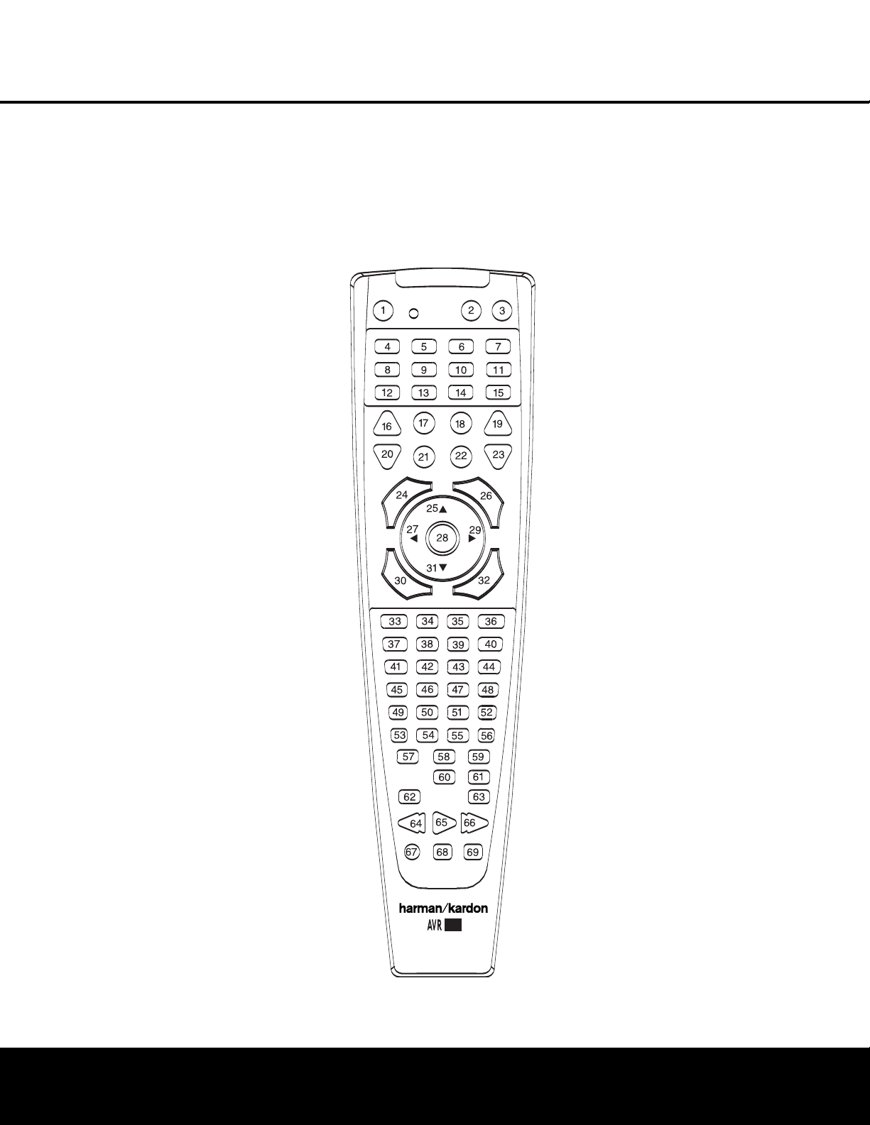
42 PROGRAMMING THE REMOTE
PROGRAMMING THE REMOTE
d
evices, counts as a step. The
P
rogram Indicator
c w
ill flash green to confirm each button press
as you enter commands.
N
OTE:
W
hile entering commands for Power On/Off of
any device during a macro sequence, press the
Mute
Button
f. DO NOT press the actual Power button.
3
. When all the steps have been entered, press the
Sleep Button j to enter the commands. The
red light under the
Input Selectors ef will
blink and then turn off.
Example: To program the Macro 1 button so that it
turns on the AVR 240, TV and a cable box, follow
these steps:
• Press the
Macro 1 Button T and Mute
Button
f at the same time and then release
them.
• Note that the
Program Indicator c will flash
amber.
• Press the
AVR Selector f.
• Press the
Mute Button f to store the
AVR 240’s Power On command.
• Press the
VID 3 Input Selector Button e to
indicate the next command is for “TV Power On.”
• Press the
Mute Button f to store the TV
Power On Command.
• Press the
VID 2 Input Selector Button e to
indicate the next command is for “Cable Power On.”
• Press the Mute Button f to store the Cable
Power On command.
• Press the
Sleep/Channel Up Button j to
complete the process and store the macro
sequence
.
After following these steps
,
each time you press
the
Macro 1 Button T, the remote will send
the Power On/Off command.
Erasing Macro Commands
T
o remove the commands that have been pro
-
grammed into one of the Macro buttons, follow these
steps:
1. Press the
Mute Button f and the Macro
Button
T that contains the commands you
wish to erase
.
2. The
Program Indicator c will flash amber,
and the LED under the
AVR Selector f will
tur
n red.
3
. Within ten seconds, press the
S
urround Mode
S
elector/Channel Down Button
k.
4. The red LED under the
AVR Selector f will
go out, and the
Program Indicator c will turn
green and flash three times before it goes out.
5
. When the
P
rogram Indicator
c g
oes out, the
Macro has been erased.
Figure 18
Programmed Device Functions
Once the AVR 240’s remote has been programmed for
the codes of other devices, press the appropriate
Input
Selector
e to change the remote from controlling
the AVR 240 to controlling the additional product. When
y
ou press any one of the selectors, it will briefly flash in
red to indicate that you have changed the device being
controlled.
W
hen operating a device other than the AVR 240, the
controls may not correspond exactly to the function
printed on the remote or button. Some commands,
such as the volume control, are the same as they are
with the AVR 240. Other buttons will change their
function so that they correspond to a secondary label
on the remote. For example, the Sleep and Surround
mode selector buttons also function as the Channel Up
and Channel Down buttons when operating most TV
sets, VCRs or cable boxes. The Channel Up/Down
indication is printed directly on the remote. For many
standard CD players, cassette decks, VCRs and DVD
functions, the standard function icons are printed on
top of the buttons.
For some products, however, the function of a particu-
lar button does not follow the command printed on
the remote. In order to see which function a button
controls, consult the Function List tables on pages 44
and 45. To use those tables, first check the type of
device being controlled (e.g., TV, VCR). Next, look at
the remote control diagram in Figure 18. Note that
each button has a number on it.
T
o find out what function a particular button has for
a specific device, find the button number on the
Function List and then look in the column for the device
you are controlling. For example, button number 46
is the Direct button for the AVR 240, but it is the
“Favorite” button for many cable television boxes
and satellite receivers. Button number 32 is the Delay
button for the AVR 240, but the Open/Close button for
CD players
.
NOTE: The numbers used to describe the button
functions in Figure 18 for the purposes of describing
how a button operates are a different set of numbers
than those used in the rest of this manual to describe
the button functions for the A
VR
240.
NOTES ON USING THE AVR 240 REMOTE WITH
OTHER DEVICES.
• Manufacturers may use different code sets for the
same product category
.
F
or that reason, it is impor-
tant that you check to see whether the code set you
have entered operates as many controls as possible.
If it appears that only a few functions operate, check
to see whether another code set will work with more
buttons.
240
®

PROGRAMMING THE REMOTE 43
PROGRAMMING THE REMOTE
•
When a button is pressed on the AVR 240 remote,
t
he red light under the
I
nput Selector
e
f
f
or
the product being operated should flash briefly. If
the Device Control Selector flashes for some but
not all buttons for a particular product, it does NOT
i
ndicate a problem with the remote but rather that
no function is programmed for the button being
pushed.
Volume Punch-Through
The AVR 240’s remote may be programmed to oper-
ate the
Volume Control b and Mute f func-
tions of either the TV or the AVR 240 in conjunction
with any of the devices controlled by the remote. For
example, since the AVR 240 will likely be used as the
sound system for TV viewing, you may wish to have
the AVR 240’s volume activated, although the remote
is set to run the TV. Either the AVR 240 or TV volume
control may be associated with any of the remote’s
devices. The factory default setting is to have the
AVR 240’s volume activated for all devices except
TAPE. To program the remote for Volume Punch-
Through, follow these steps:
1. Press the
Input Selector e for the unit you wish
to have associated with the volume control and the
Mute Button f at the same time until the red
light appears under the
Input Selector e; the
Program Indicator c will flash amber.
2. Press the
Volume Up Button b; the Program
Indicator c will stop flashing and stay amber.
3. Press either the AVR Selector f or the Input
Selector
e, depending on which system’s
volume control you wish to have attached for the
punch-through mode. The
Program Indicator c
will blink green three times and then go out to con-
firm the data entry.
Example: T
o have the
A
VR 240’s volume control
activated even though the remote is set to control
the TV, first press the
Video 3/TV Input Selector
e and the Mute Button f at the same time.
Next, press the
Volume Up Button b, followed
by the
AVR Selector f.
NOTE: Should you wish to return the remote to the
original configuration after entering a Volume Punch-
Through, you will need to repeat the steps shown
above
.
However, press the same Input Selector in
Steps 1 and 3.
Channel Control Punch-Through
The AVR 240’s remote may be programmed to operate
so that the channel control function for either the TV,
cable or satellite receiver used in your system may be
used in conjunction with one of the other devices con-
trolled by the remote. For example, while using and con-
t
rolling the VCR, you may wish to change channels on a
c
able box or satellite receiver without having to change
the device selected by the AVR 240 or the remote.
To program the remote for Channel Control Punch-
Through, follow these steps:
1. Press the
Input Selector Button ef for the
device you wish to have the channel control associ-
ated with and the
Mute Button f at the same
t
ime until the red light appears under the
I
nput
Selector
ef and the Program Indicator
c flashes amber.
2. Press the
Volume Down Button b. The
Program Indicator c will stop flashing and
stay amber.
3. Press and release the
Input Selector Button e
for the device that will be used to change the
channels
. The
Program Indica
tor
c will blink
green three times and then go out to confirm the
data entry.
Example: To control the channels using your cable
box or satellite receiver while the remote is set to
control the VCR, first press the
VID 1/VCR Input
Selector Button
e and the Mute Button f
at the same time. Next, release them and press the
Volume Down Button b, followed by the VID 2/
Cable/Sat Input Selector Button
e.
NOTE: To remove the Channel Control Punch-Through
and return the remote to its original configuration, repeat
the steps shown in the example above. However, press
the same Input Selector in Steps 1 and 3.
Transport Control Punch-Through
The AVR 240’s remote may be programmed to operate
so that the
Transport Control Functions ` (Play,
Stop, Fast Forward, Rewind, Pause and Record) for a
VCR, DVD or CD will operate in conjunction with one of
the other devices controlled by the remote
.
F
or exam-
ple, while using and controlling the TV, you may wish to
start or stop your VCR or DVD without having to change
the device selected by the AVR 240 or the remote. The
factory default setting is to have the DVD’s transport
controls activated when the
AVR, VID2/CABLE or SAT
or VID3/TV devices have been selected. T
o program
the remote for Transport Control Punch-Through, follow
these steps:
1.
Press the
Input Selector ef for the device
you wish to have the channel control associated with
and the
Mute Button f at the same time until
the red light appears under the
Input Selector e
and the Program Indicator c flashes amber.
2.
Press the
Play Button `.
The
Program
Indicator
c will stop flashing and stay amber.
3. Press and release the
Input Selector Button e
f
or the device that will be used to change the chan-
nels. The
Program Indicator c will blink green
three times and then go out to confirm the data
entry.
Example: To control the transport of a DVD player
while the remote is set to control the TV, first press
the
VID 3/TV Input Selector Button e and the
Mute Button f at the same time. Next, release
them and press the
Play Button `, followed by
the
DVD Input Selector Button e.
NOTES:
• To remove the Channel Control Punch-Through and
return the remote to its original configuration, repeat
the steps in the example above. However, press the
same Input Selector in Steps 1 and 3.
• Before programming the remote for Volume, Channel
or Transport Punch-Through, make certain that any
programming needed for the specific TV, CD, DVD,
cable or satellite receivers has been completed.
• The AVR 240 remote is preprogrammed at the
factory so that the
Transport Control Functions
` operate the DVD player whenever the AVR
device is selected.
Resetting the Remote Memor
y
As you add components to your home theater system,
occasionally you may wish to totally reprogram the
remote control without the confusion of any commands,
macros or “Punch-Through” programming that you may
have done. To do this, it is possible to reset the remote
to the original factory defaults and command codes by
following these steps. However, once the remote is
reset, all commands or codes that you have entered
will be erased and will need to be reentered:
1. Press any of the
Input Selector Buttons e and
the
“O”
Button
r at the same time until the
Program
Indica
tor
c begins to flash amber
.
2. Press the
“3” Button r three times.
3. The red LED under the
Input Selector e will go
out and the
Program Indicator c will stop flash-
ing and tur
n green.
4. The
Program Indicator c will remain green until
the remote is reset. Note that this may take a while,
depending on how many commands are in the
memory that need to be erased.
5.
When the
Program
Indica
tor
c goes out,
the
remote has been reset to the factor
y settings.

No. Button Name AVR Function DVD CD/CD-R Tape VCR (VID1) CBL (VID2) SAT (VID2) TV (VID3)
(DMP)
1 Power On Power On Power On Power On Power On Power On Power On Power On Power On
2 Power Off Power Off Power Off Power Off Power Off Power Off Power Off Power Off Power Off
3 M
ute
M
ute Mute Mute Mute Mute Mute Mute Mute Mute
4 AVR AVR Select AVR Select AVR Select AVR Select AVR Select AVR Select AVR Select AVR Select AVR Select
5 D
VD
D
VD Input Select DVD Select DVD Select DVD Select DVD Select DVD Select DVD Select DVD Select DVD Select
6 CD CD Input Select CD Select CD Select CD Select CD Select CD Select CD Select CD Select CD Select
7 Tape Tape Input Select Tape Select Tape Select Tape Select Tape Select Tape Select Tape Select Tape Select Tape Select
8 VID 1 (VCR) Video 1 Select VCR Select VCR Select VCR Select VCR Select VCR Select VCR Select VCR Select VCR Select
9 VID 2 (CBL/SAT) Video 2 Select CBL/SAT Select CBL/SAT Select CBL/SAT Select CBL/SAT Select CBL Select SAT Select CBL/SAT Select CBL/SAT Select
10 VID 3 (TV) Video 3 Select TV Select TV Select TV Select TV Select TV Select TV Select TV Select TV Select
11 VID 4 Video 4 Select Video 4 Select Video 4 Select Video 4 Select Video 4 Select Video 4 Select Video 4 Select Video 4 Select Video 4 Select
12 Dim Dimmer Dimmer
13 AM/FM Tuner Select Tuner Select Tuner Select Tuner Select Tuner Select Tuner Select Tuner Select Tuner Select Tuner Select
14 6CH/8CH 6/8 Ch. Input Select
6/8 Ch. Input Select 6/8 Ch. Input Select
6/8 Ch. Input Select
6/8 Ch. Input Select 6/8 Ch. Input Select 6/8 Ch. Input Select 6/8 Ch. Input Select
6/8 Ch. Input Select
15 (DMP) The Bridge (DMP)
The Bridge (DMP) Select The Bridge (DMP) Select The Bridge (DMP) Select The Bridge (DMP) Select The Bridge (DMP) Select
The Bridge (DMP) Select
The Bridge (DMP) Select
The Bridge (DMP) Select
16 Sleep/CH+ Sleep Audio Channel + Channel + Channel + Channel +
17 Test Tone Test Tone
18 T/V TV/DVD or V. OFF Input Select TV/VCR TV/CBL TV/SAT TV/VCR
19 Vol Up Volume Up Volume Up Volume Up Volume Up Volume Up Volume Up Volume Up Volume Up
20 Surr/CH–
DSP Surround Mode Select
Disc Menu or Title CDR Select Channel – Channel – Channel – Channel –
21 Night Night Mode Select Subtitle On/Off CDP Select
22 Spare HD Mode
23 Vol Down Volume Down Volume Down Volume Down Volume Down Volume Down Volume Down Volume Down Volume Down
24 CH./Guide Channel Trim Title or Disc Menu Continuous Play Info/Guide Info/Guide
25
⁄
Move/Adjust Up Up Up Up Up Up
26 Speaker/Menu Speaker Adjust Menu or Setup Intro Scan Menu Menu Menu Menu Menu
27 fi Move/Adjust Left Left Left Left Left Left Scroll –
28 Set Set Enter Enter Enter Enter Enter Select
29 fl Move/Adjust Right Right Right Right Right Right Scroll +
30 Digital/Exit Digital Input Select Open/Close Repeat
31
¤
Move/Adjust Down
Down Down Down Down Down
32 Delay/Prev. Ch. Delay Adjust Return or Status Open/Close Prev Channel Prev Channel Prev Channel Shuffle
33 1 111 1111
34 2 222 2222
35 3 333 3333
36 4 444 4444
37 5 555 5555
38 6 6
6
6
66 66
39 7 777 7777
40 8 888 8888
41 Tun-M Tuner Mode Chapter+ or Zoom Repeat
42 9 999 9999
43 0 000 0000
44 Memor
y
Memor
y
Audio or Playlist
T
ime
The
Bridge
TM
The
Bridge
TM
FUNCTION LIST
44 FUNCTION LIST

FUNCTION LIST 45
FUNCTION LIST
No. Button Name AVR Function DVD CD/CD-R Tape VCR (VID1) CBL (VID2) SAT (VID2) TV (VID3)
(DMP)
45 Tuning Up Tuning Up Next Chapter Track Direct Cancel PPV Cancel Sleep Album +
4
6
D
irect
D
irect Tuner Entry Angle Random Play FAV FAV
47 Clear Clear Clear Clear Clear Bypass Next
48 Preset Up Preset Tune Up Slow Forward +10 Music Alt Chapter +
49 Tuning Down Tuning Down Prev Chapter Track Increment Album –
50 OSD OSD Program OSD OSD OSD OSD
5
1
D
. Skip
D
isc Skip (DVD) Disc Skip Disc Skip
52 Preset Down Preset Tune Down Slow Rev Chapter –
53 M1 Macro 1 Macro 1 Macro 1 Macro 1 Macro 1 Macro 1 Macro 1 Macro 1
54 M2 Macro 2 Macro 2 Macro 2 Macro 2 Macro 2 Macro 2 Macro 2 Macro 2
55 M3 Macro 3 Macro 3 Macro 3 Macro 3 Macro 3 Macro 3 Macro 3 Macro 3
56 M4 Macro 4 Macro 4 Macro 4 Macro 4 Macro 4 Macro 4 Macro 4 Macro 4
57 Dolby Surround Dolby Modes
58 DTS Surround DTS Digital Modes
59 DTS Neo:6 DTS Neo:6 Select
60 Logic 7 Logic 7 Select
61 Stereo Stereo Mode Select
62 Skip Down Skip – (DVD) Step – Skip – Scan – Skip – (DVD) Skip – (DVD) Skip – (DVD) Playlist –
63 Skip Up Skip + (DVD) Step + Skip + Scan + Skip + (DVD) Skip + (DVD) Skip + (DVD) Playlist +
64 Rewind (‹‹) R. Search (DVD) R. Search R. Search Rewind Rewind R. Search (DVD) R. Search (DVD) R. Search (DVD) R. Search
65 Play (‹›) Play (DVD) Play Play R. Play/F. Play Play Play (DVD) Play (DVD) Play (DVD) Play/Pause
66 F F (››) F. Search (DVD) F. Search F. Search Fast Fwd Fast Fwd F. Search (DVD) F. Search (DVD) F. Search (DVD) F. Search
67 Record Record Record/Pause Record
68 Stop Stop (DVD) Stop Stop Stop Stop Stop (DVD) Stop (DVD) Stop (DVD)
69 Pause Pause (DVD) Pause Pause Pause Pause (DVD) Pause (DVD) Pause (DVD)
The
Bridge
TM

M
anufacturer/Brand Setup Code Number
AIWA 027
A MARK 122 132
ADMIRAL 192
AKAI 123 160
AMPRO 164
ANAM 045 106 109 112 122
AOC 122 123 128
BLAUPUNKT 084
BROKSONIC 205 206
CANDLE 123 128
CAPEHART 059
CENTURION 123 171
CENTRONIC 045
CITIZEN 045 123 128 132
CLASSIC 045
CONCERTO 128
CONTEC 045
CORANDO 172
CORONADO 132
CRAIG 045 157
158
159
CROWN 045 132
CURTIS MATHES 123 128 132
CXC 045
DAEWOO 045 087 102 105 106 108 111 114 116 119 127 128 132
DAYTRON 128 132
DIGI LINK 200
DYNASTY 045
DYNATECH 063
ELECTROHOME 115 132
EMERSON 045 123 128 132 139 157 158 159 162 205
FUNAI 045
FUTURETECH 045
GE 029 087 121 123 128 133 145 159 163
GOLDST
AR/LG
101
110
122 128 132
GRUNDIG 193
HALL MARK 128
HARMAN KARDON 201
HITACHI 123 128 132 144 147
INFINITY 148
INKEL 120
JBL 148
JC PENNEY 115 123 128 132 145
JENSEN 019
JVC 079 087 134
KAWASHO 173
KEC 045
KENWOOD 123 204
KMC 132
KTV 045 123 132 162
LLOYTRON
172
173
LODGENET 069
SETUP CODE TABLE: TV
46 SETUP CODES

SETUP CODES 47
SETUP CODE TABLE: TV
Manufacturer/Brand Setup Code Number
L
OGIK 069
LUXMAN 128
LXI 077 145 148
MAGNAVOX 030 123 128 132 145 148
MARANTZ 115 123 148
MATSUI 148
M
EMOREX 069 128
METZ 084
MGA 115 123 128
MINERVA 084
MITSUBISHI 077 115 123 128 160 167 168
MTC 175 176
NATIONAL 148 177 179 180 181 182
NEC 115 121 123 125
NIKEI 045
ONKING 045
ONWA 045
OPTONICA 077
ORION 207 208 209 210 211
PANASONIC 087 148 169
PHILCO 045 115 123 128 132 148
PHILIPS 033 034 035 036 123 128 132 145 148
PIONEER 024 123 128
PORTLAND 128 132
PROSCAN 133
PROTON 059 122 128 132 165
QUASAR 032 087
RADIO SHACK 045 128 132 180 196 197
RCA 021 115 123 128 133 145 161 163
REALISTIC 045 167 196
RUNCO 152 153
SAA 183
SAMPO 059 123 128
SAMSUNG
020
022 124 128 132 145
SANYO 026 054
SCOTT
045 128 132
SEARS
128
132
145
SHARP 077 128 132
SIEMENS
084
SIGNA
TURE
069
SONY 028 031 117 130 136 194 212
SOUNDESIGN
045 128
SPECTRICON
122
SSS 045
SYLVANIA 025 123 128 145 148
SYMPHONIC
184
TANDY 077
TATUNG 063
TECHNICS
181
TECHWOOD 128

Manufacturer/Brand Setup Code Number
T
EKNIKA 045 069 115 123 128 132
TELERENT 069
TERA 156
THOMSON 190 191
TMK 128
TOSHIBA 063 129 202
T
OTEVISION 132
VIDEO CONCEPTS 160
VIDTECH 128
WARDS 069 128 132 148
YAMAHA 123 128
YORK 128
YUPITERU 045
ZENITH 069 090
ZONDA 122
SETUP CODE TABLE: TV
48 SETUP CODES

SETUP CODE TABLE: VCR
SETUP CODES 49
Manufacturer/Brand Setup Code Number
A
IWA 040
AKAI 048 108 109 126
AMPRO 076
A
SA 134
AUDIO DYNAMICS 018 048
BROKSONIC 110 147
C
ANDLE 134 135
CANON 135 140
CAPEHART 094
CITIZEN 134
CRAIG 045 116
DAEWOO 017 094 104
DA
YTRON 094
DBX 018 048
DYNATECH 040
EMERSON 013 040 042 110 112
FISHER 017
FUNAI 040
GE 076 095 124
GO VIDEO 113
GOLDSTAR/LG 018 107
HARMAN KARDON 018 049
HITACHI 040 048
JC PENNEY 018 045
JENSEN 048
JVC 018 048 111 132
KENWOOD 020 048
LLOYD 040
LXI 020 040
MAGIN 045
MAGNAVOX 040
MARANTZ 018
MEMOREX
017
020
040
052
053
054 076
MGA 049
MITSUBISHI 049
131
MUL
TITECH 040
NAD 139
NATIONAL
140
NEC
018
048
NORDMENDE 048
OPTIMUS 159
ORION
147
PANASONIC 125 150 167 172
PHILCO 040
PHILIPS
040
075
PORTLAND 094
PULSAR
076
Q
UASAR
001
125
RADIO SHACK 055 134 140 142 158 159
RCA
095
124 125 157 172
REALISTIC
017
020
040
045
159

Manufacturer/Brand Setup Code Number
S
ALORA 020
SAMSUNG 045 051 095 105 109
SANSUI 048 116 147
S
ANYO 017 020
SCOTT 110 112
SEARS 017 020
S
HARP 129 156
SONY 080 129
SOUNDESIGN 040
SYLVANIA 040
SYMPHONIC 040
TANDY 017 040
TASHICO 134
TATUNG 048
TEAC 040 048
TEKNIKA 040
THOMAS 040
TiVo 012
TMK 013
TOSHIBA 112 155
TOTEVISION 045
UNITECH 045
VECTOR RESEARCH 018
VIDEO CONCEPTS 018 040
VIDEOSONIC 045
WARDS 040 045 112
YAMAHA 018 040 048
ZENITH 040 050 076 083
50 SETUP CODES
SETUP CODE TABLE: VCR

SETUP CODE TABLE: CD
SETUP CODES 51
M
anufacturer/Brand Setup Code Number
ADCOM 063 069
AIWA 072 111 118 156 170
A
KAI 050 177 184
AUDIO TECHNICA 053
AUDIOACCESS 125
A
UDIOFILE 211
BSR 044
CALIFORNIA AUDIO 109
C
APETRONIC 070
CARRERA 087
CARVER 136 140 141 143 144 145 185 186
CASIO 117 166
CLARINETTE 166
DENON 187 188 213
EMERSON 052 093 108
FISHER 055 095
FRABA 117
FUNAI 126
GE 164
GENEXXA 108
GOLDSTAR/LG 016 087
HAITAI 099 214
HARMAN KARDON 001 002 025 054 190
HITACHI 093
INKEL 216
JC PENNEY 098 147
JENSEN 153
JVC 176 195 196
KENWOOD 030 062 078 079 148 151 176 178 181
LOTTE 108
LUXMAN 077 102
LXI 164
MAGNAVOX
039
113
MARANTZ 058 084 191 192 193
MCINTOSH 194
MCS
080
098
MITSUMI 152
MODULAIRE 166
NAD
013
074 197
198
NAKAMICHI 199 200 201
NEC 069
NIKK
O
053 055
ONKYO 037 038 045 046 171 175 202 203
OPTIMUS 065
089 091 092 099 104 212
P
ANASONIC
075 109
119 158
183 204
PHILIPS 039 138 149 209
PIONEER
071 094 100 112 123 131 161 162 215
PROTON
210
QUASAR 109
RADIO SHACK
126 166 213
RCA
024
081
093
150

SETUP CODE TABLE: DVD
M
anufacturer/Brand Setup Code Number
RCX 169
REALISTIC 058 093 095 104 105 108 164 166
S
ANSUI 047 081 134 157 172
SANYO 033 082 095
SCOTT 108
S
HARP 058 105 114 151 159 167 180 181
SHERWOOD 003 041 058 105 133
SONY 103 115 116 118 132 139 163 205 206 207 208 212 217
S
OUNDSTREAM 124
SYMPHONIC 059 110
TAEKWANG 177
TEAC 011 058 085 086 106 107 110 121 137 146 154
THETA DIGITAL 039
TOSHIBA 013 074 097 151 155 173
VECTOR RESEARCH 087
VICTOR 120 130
WARDS 095
YAMAHA 019 031 053 061 135 169
YORK 166
Manufacturer/Brand Setup Code Number
APEX DIGITAL 061
DENON 019 051
GE 003 004
GOLDSTAR/LG 005 055 064 066
HARMAN KARDON 001 002
JVC 006
MAGNAVOX 056
MARANTZ
059
MITSUBISHI 023
NAD 062
ONKYO 009 048
PANASONIC 024 030 044
PHILIPS 056
PIONEER 041 065
PROCEED 060
PROSCAN 003 004
RCA 003 004
SAMSUNG 053 054
SHARP 028
SONY 043 045
THOMSON 003 004
TOSHIBA 009 058 067
YAMAHA 030 063
ZENITH
005
055
064
52 SETUP CODES
SETUP CODE TABLE: CD

SETUP CODE TABLE: SAT
SETUP CODES 53
Manufacturer/Brand Setup Code Number
ALPHASTAR 472
ALPHASTAR DBS 450
A
LPHASTAR DSR 442
BIRDVIEW 425
CHANNEL MASTER 320 321 325 361
C
HAPARRAL 315 316 451
CITOH 360
DRAKE 313 317 318 413 481
D
X ANTENNA 331 352 379 483
ECHOSTAR 395 397 452 453 463 477 478 484 485
ELECTRO HOME 392
FUJITSU 324 329 334
GENERAL INSTRUMENT
303 311 323 365 403 454 468 474
HITACHI DBS 455
HOUSTON TRACKER 463
HUGHES 437 489
JANIEL 366
JERROLD 454 468 484
KATHREIN 410
LEGEND 453
MACOM 317 365 369 370 371
MAGNAVOX 461 473
MEMOREX 453
NEXTWAVE 423
NORSAT 373
OPTIMUS 466
PACE DSS 487
PANASONIC 366 469
PANASONIC DBS 457
PANSAT 420
PERSONAL CABLE 418
PHILIPS 375
PICO 407
PRESIDENT 381 404
PRIMESTAR 412 454 468 475
RCA 301 439 465 490
RCA DSS 458
REALISTIC 349 480
SAMSUNG 442
SATELLITE SERVICE CO 335 388
SCIENTIFIC ATLANTA 339
SONY 405
STAR CHOICE DBS 459
STARCAST 347
SUPER GUIDE 327 423
TEECOM 330 333 390 391 393 409
TOSHIBA 302 426 460 461 462 470
UNIDEN 323 332 348 349 350 351 354 355 381 383 389 403 466 479 480
ZENITH 384 385 387 394 419 488

Manufacturer/Brand Setup Code Number
H
ARMAN KARDON 001
SETUP CODE TABLE: CBL
Manufacturer/Brand Setup Code Number
A
BC 001 011
ALLEGRO 111
AMERICAST 212
ARCHER 112
BELCOR
113
CABLE STAR 033 113
CITIZEN 111
COLOUR VOICE 085 090
DIGI 114
EAGLE 186
EASTERN 066 070
ELECTRICORD 039
EMERSON 112
FOCUS 116
G.I. 001 011 017 096 097
GC ELECTRONICS 113
GEMINI 032 060
GENERAL 210
GENERAL INSTRUMENT 210
GOODMIND 112
HAMLIN 056 099 100 101 117 175 208
HITACHI 001 188
JASCO 111
JERROLD 001 002 011 017 073 096 097 162 188 210
LINDSAY 118
MACOM 191
MAGNAVOX 017 019 068
MOVIE TIME 035 039
NSC 035 190
OAK 197 220
PACE 179
PANASONIC 053 176 177 189 214
PANTHER 114
PHILIPS 013 019 020 085 090
PIONEER 001 041 119 171 209 215 216
POPULAR MECHANICS 116
PRELUDE 120
PRIMESTAR 162
RADIO SHACK 111 112 213
RCA 053 214
RECOTON 116
REGAL 056 099 100 101 208
54 SETUP CODES
SETUP CODE TABLE: TAPE

SETUP CODES 55
SETUP CODE TABLE: CBL
M
anufacturer/Brand Setup Code Number
REMBRANT 032
S
AMSUNG 003 072 186
SCIENTIFIC ATLANTA 183 203 221 222
SEAM 121
S
IGNATURE 001 188
SPRUCER 053 081 177 189
STARCOM 002 011 163
S
TARGATE 120
TANDY 024
TELECAPATION 028
TEXSCAN 036
TFC 122
TIMELESS 123
TOCOM 170 205
UNITED CABLE 011
UNIVERSAL 033 034 039 042 113
VIDEOWAY 124 211
VIEWSTAR 019 025 086 089 190
ZENITH 065 125 211 219
ZENTEK 116

SYMPTOM CAUSE SOLUTION
U
nit does not function when Main • No AC Power • Make certain AC power cord is plugged into
P
ower Switch is pushed a live outlet
• Check to see whether outlet is switch-controlled
Display lights, but no sound • Intermittent input connections • Make certain that all input and speaker connections
or picture are secure
•
M
ute
i
s on • Press
M
ute Button
f
• Volume control is down • Turn up volume control
No sound from any speaker; • Amplifier is in protection mode • Check speaker wire connections for shorts at receiver and
light around power switch is red due to possible short speaker ends
• Amplifier is in protection mode • Contact your local Harman Kardon service center
due to internal problems
No sound from surround or • Incorrect surround mode • Select a mode other than Stereo
center speakers • Input is monaural • There is no surround information from mono sources
• Incorrect configuration • Check speaker mode configuration
• Stereo or Mono program material • The surround decoder may not create center- or rear-channel
information from nonencoded programs
Unit does not respond to • Weak batteries in remote • Change remote batteries
remote commands • Wrong device selected • Press the AVR selector
• Remote sensor is obscured • Make certain front panel sensor is visible to remote
or connect remote sensor
Intermittent buzzing in tuner • Local interference • Move unit or antenna away from computers, fluorescent
lights, motors or other electrical appliances
Letters flash in the channel indicator • Digital audio feed paused • Resume play for DVD
display and digital audio stops • Check that Digital Input is selected
In addition to the items shown above, additional information on troubleshooting possible problems with your AVR 240, or installation-related issues, may be found in the list of
“Frequently Asked Questions” which is located in the Product Support section of our Web site at www.harmankardon.com.
Processor Reset
In the rare case in which the unit’
s operation or the dis-
plays seem abnormal, the cause may involve the erratic
operation of the system’s memory or microprocessor.
To correct this problem, first unplug the unit from the
AC wall outlet and wait at least three minutes
.
After the
pause, reconnect the AC power cord and check the
unit’s operation. If the system still malfunctions, a sys-
tem reset may clear the problem.
To clear the AVR 240’s entire system memory includ-
ing tuner presets, output level settings, delay times and
speaker configuration data, first place the AVR in
Standby Mode, and then press and hold the
Tone
Mode Button
5 button for three seconds
.
The unit
will tur
n on automatically
.
NOTE: Resetting the processor will erase any configu-
ration settings you have made for speakers, output
levels, surround modes, digital input assignments as
well as the tuner presets
.
The unit will be returned to
the factory presets, and all settings for these items
must be reentered.
If the system is still operating incorrectly, there may
have been an electronic discharge or severe AC line
interference that has corrupted the memory or
microprocessor.
If these steps do not solve the problem,
consult an
authorized Harman Kardon service center.
TROUBLESHOOTING GUIDE
56 TROUBLESHOOTING

TECHNICAL SPECIFICATIONS 57
AVR 240 TECHNICAL SPECIFICATIONS
Audio Section
S
tereo Mode
Continuous Average Power (FTC)
6
5 Watts per channel, 20Hz–20kHz,
@
<0.07% THD, both channels driven into 8 ohms
Six-Channel Surround Modes
P
ower per Individual Channel
Front L&R channels:
5
0 Watts per channel
@
<0.07% THD, 20Hz–20kHz into 8 ohms
Center channel:
50 Watts @ <0.07% THD, 20Hz–20kHz into 8 ohms
Surround (L & R Side, Back) channels:
50 Watts per channel
@ <0.07% THD, 20Hz–20kHz into 8 ohms
Input Sensitivity/Impedance
Linear (High-Level) 200mV/47k ohms
Signal-to-Noise Ratio (IHF-A) 100dB
Surround System Adjacent Channel Separation
Pro Logic 40dB
Dolby Digital 55dB
DTS 55dB
Frequency Response
@ 1W (+0dB, –3dB) 10Hz –130kHz
High Instantaneous
Current Capability (HCC) ±35 Amps
Transient Intermodulation
Distortion (TIM) Unmeasurable
Slew Rate 40V/µsec
FM Tuner Section
Frequency Range 87.5–108.0MHz
Usable Sensitivity IHF 1.3µV/13.2dBf
Signal-to-Noise Ratio Mono/Stereo 70/68dB
Distortion Mono/Stereo 0.2/0.3%
Stereo Separation 40dB @ 1kHz
Selectivity ±400kHz, 70dB
Image Rejection 80dB
IF Rejection
90dB
A
M Tuner Section
F
requency Range 520–1720kHz
Signal-to-Noise Ratio 45dB
Usable Sensitivity Loop 500µV
Distortion 1kHz, 50% Mod 0.8%
S
electivity ±10kHz, 30dB
V
ideo Section
T
elevision Format NTSC
Input Level/Impedance 1Vp-p/75 ohms
Output Level/Impedance 1Vp-p/75 ohms
Video Frequency Response
(Composite and S-Video) 10Hz–8MHz (–3dB)
Video Frequency Response
(Component Video) 10Hz–50MHz (–3dB)
General
Power Requirement AC 120V/60Hz
Power Consumption 65W idle, 540W maximum
(6 channels driven)
Dimensions (Product) (Shipping)
Width 17.3 inches (440mm) 21.5 inches (545mm)
Height 6.6 inches (168mm) 9.9 inches (251mm)
Depth 15 inches (382mm) 17.9 inches (455mm)
(Product) (Shipping)
Weight 24.4 lb (11.1kg) 29.3 lb (13.3kg)
Depth measurement includes knobs, buttons and terminal connections.
Height measurement includes feet and chassis.
All features and specifications are subject to change without notice.
Harman Kardon, Harman International, Power for the Digital Revolution and Logic 7 are registered trademarks,
and The Bridge and
are trademarks, of Harman International Industries, Incorporated.
*Manufactured under license from Dolby Laboratories. Dolby, Pro Logic and the double-D symbol
are registered trademarks of Dolby Laboratories.
DTS, DTS Surround, DTS-ES, DTS 96/24 and DTS Neo:6 are registered trademarks of DTS, Inc.
VMAx is a registered trademark of Har
man Inter
national Industries, Incorporated, and is an
implementation of Cooper Bauck
Transaural Stereo under patent license.
SACD is a trademark of Sony Electronics
,
Inc
.
Apple and iPod are registered trademarks, and Shuffle is a trademark, of Apple Computer, Inc.
The
Bridge
T
M
Please register your product on our
Web site at www.harmankardon.com. Note: You’ll need the product’s serial number.
At the same time you can choose to be notified about our new products and/or special promotions.

5
-Channel Stereo 23, 34
6-Channel/8-Channel Direct Input 9, 15, 31
7-Channel Stereo 23, 34
AC Power Connections 9, 16
A
dvanced Features 38–39
Advanced Select Menu 38
A
nalog Bypass 13, 23, 34
Antenna Terminals 8, 10, 15
Audio Equipment Connections 8–10, 15
Audio Setup Menu 21
A
uto Mode Tuning 6, 12, 13, 37
Auto Polling 21
Auto Search Method 41
A/V Sync Delay 29–30
Cable Television 4, 10, 12, 15–16, 41,
42, 43, 44–45, 54–55
CD 7, 12, 15, 44–45, 51–52
Channel Adjust Menu 29
Channel-Control Punch-Through 43
Cleaning and Maintenance 4
Coaxial Digital Audio Jacks 6, 8, 9, 15–16, 20
31, 35, 36, 37
Code Readout 41
Component Video 3, 9, 13, 20
Composite Video 6, 8, 10, 15–16
Default Surround Mode 40
Delay Adjust Menu 28
Delay Settings 25, 28–29
Description and Features 3
Digital Audio Playback 32–37
Digital Source Selection 6, 12, 20, 35
Dimming Front-Panel Display 12
Direct Code Entry 41
DMP 6, 8, 9, 11, 13, 14, 15, 21, 31, 37–38,
44–45
Dolby 3, 6, 9, 11, 13, 15, 18, 20, 21, 22, 26,
27, 28, 30, 32–37, 40, 57
Dolby Digital 3, 6, 9, 13, 15, 18, 20, 21, 22,
26, 27, 28, 30, 32–37, 40
Dolby Headphone 7, 32, 34
Dolby Pro Logic 3, 13, 22, 24, 28, 30,
32–37, 57
Dolby Virtual Speaker 7, 26, 34
DSP Surround Modes 11, 12, 23, 32, 34
DTS 3, 6, 9, 11, 13, 18, 20, 21, 22-23, 32
33–34, 35–36, 37, 40, 57
DTS Neo:6 3, 11, 13, 21, 23, 32, 33,
35–36, 57
DTS-ES 3,
13, 18, 21, 23, 32, 33, 35–36, 57
DVD 3, 8, 9, 10, 11, 12, 13, 14, 15, 16,
19,
20,
21, 28,
35,
36,
37, 41,
42,
43,
44,
45, 52
DVD-Audio 9, 14, 15, 16, 31
EzSet+ 23–25
F
ront-Panel Controls 5–7
Front-Panel Jacks 6, 16, 31, 32
Front-Panel-Display Fade 39
Full OSD 19, 39–40
F
ull-OSD Time-Out 39–40
Hall 34
H
eadphones 5, 32
HDTV Tuner 9, 10, 15, 16, 21, 35
iPod
®
3, 9, 13, 14, 15, 21, 31, 37–38, 44–45
Input-Independent Speaker Setup 27
I
nput Setup Menu 20
Input Titling 3, 20
Installation 15–16
Installation Location 4
IR Receiver (Remote Sensor) 5, 7, 16
Logic 7 3, 6, 11, 13, 18, 20, 21, 23, 26,
28, 32, 33, 57
Macros 13, 41–42, 45
Manual Mode Tuning 6, 12, 13, 37
Manual Setup Menu 25
Master Menu 19
Memory Backup 38
Mute 6, 11, 14, 31, 41–43, 56
Night Mode 11, 12, 22, 36
On-Screen Display 19, 39–40
Operation 31–38
Optical Digital Audio Jacks 6, 8, 9, 15–16, 20,
31, 35, 36, 37
Output Level Adjustments 25, 29–30
Output Level Trim Adjustment 38
PCM 36
Polarity 15
Power Switches 5, 12, 19, 31
Preset Stations 6, 13, 37
Processor Reset 56
Programmed Device Functions 42–45
Programming Product Codes 41, 46–55
Punch-Through Programming 43
Quadruple Crossover 3, 27
Rear-Panel Connections 8–10
Recalling Preset Stations 6, 13, 37
Recording 37
Remote Control 11–14, 19, 41–55
Remote Control Batteries 19
Remote Control Function List 44–45
Remote Control Functions 42–45
Remote Control Setup Code Tables 46–55
Resetting the Remote 43
SACD 9,
15, 16, 31, 32
Safety Information 3, 4
Satellite
T
elevision 9, 10,
11,
15–16,
20, 32,
41,
43,
44–45,
53
Semi-OSD 19, 39
Setting Preset Stations 37
S
ettings Worksheet 59
Sleep Mode 12, 31
Source Selection 6, 12, 20, 31
Speaker Crossover Menu 27
S
peaker Placement 17–19
Speaker Selection 17
S
peaker Setup 26–28
Speaker Size Menu 26
Speaker Terminals 9, 15
Speaker Wire 15
S
peaker/Channel Input Indicators 5, 6, 36
Subwoofer 8, 9, 15, 18, 26–27, 28, 30,
33–34, 35
Surround Mode Chart 33–34
Surround Mode Selection 6, 12–13, 21–23,
32–37
Surround Off 12, 23, 32, 34
Surround Select Menu 21
Surround Setup 21–23
S-Video 6, 8, 9, 15–16
System Configuration 17–30
System Setup 19–20
Tape 8, 37, 54
Technical Specifications 57
Theater 34
The Bridge 3, 6, 8, 9, 11, 13, 14, 15, 21,
31, 37–38, 44–45
Tone Controls 5, 21, 31–32
Trademark Acknowledgements 57
Transport Controls 11, 13, 14, 37–38, 43, 45
Transport-Control Punch-Through 43
Troubleshooting Guide 56
Tuner Mode 6, 12, 37
Tuner Operation 37
Turn-On Volume Level (Volume Default) 39, 59
TV 9, 10, 11, 12–13, 15–16, 42–45, 46–48
Typographical Conventions 2
Unpacking 4
Upsampling 22
VCR 10, 15–16, 43–45, 49–50
Video Connections 8–10, 15–16, 31
Video Equipment Connections 15–16
Video Monitor 9, 10, 16, 31
VMAx 3, 12, 21, 23, 26, 34
Volume Control 6, 11, 14, 31, 56
Volume Punch-Through 43
58 INDEX
INDEX
APPENDIX 59
APPENDIX – SETTINGS WORKSHEET
FEATURE DVD VIDEO 1 VIDEO 2 VIDEO 3 DMP CD TAPE TUNER
6/8 CH. DIRECT
Input Title ––––––––
Component Video Input
Component Component Component Component
––––––––––
Component Component Component Component
Video 1 (Y/N) Video2 (Y/N) Video 2 (Y/N) Video 2 (Y/N) Video 1 (Y/N) Video 1 (Y/N) Video 1 (Y/N) Video 2 (Y/N)
Digital Audio Input
Auto Poll (On/Off)
Surround Mode
Night Mode
Front L/R Speaker Size*
Center Speaker Size*
Surround L/R Speaker Size*
Surround Back L/R Speaker Size*
Subwoofer
Front L/R Crossover
Center Crossover
Surround L/R Crossover
Surround Back L/R Crossover
LFE Setting
The
Bridge
TM
Table 1: Input Settings
Table 2: Audio Setup (Tone Control Settings)
Table 3: Delay Settings
CONTROL SETTING
Tone (In/Out)
Bass
Treble
*If the GLOBAL setting was selected, you need only indicate speaker sizes for one input.
CHANNEL SETTING
Left Front
Right Front
Center
Surround Left
Surround Right
Surround Back Left
Surround Back Right
Subwoofer
Unit (Feet/Meters)
A/V Sync Delay
Table 4: Output Level
CHANNEL SETTING
Left Front
Right Front
Center
Surround Left
Surround Right
Surround Back Left
Surround Back Right
Subwoofer
T
able 5: Advanced Settings
FEATURE SETTING
VFD Fade Time-Out
Volume Default
Default Volume Setting
Semi-OSD Time-Out
Full-OSD T
ime-Out
Default Surround Mode (On/Off)
OSD Background (Blue/Black)

®
250 Crossways P
ark Drive
, Woodbury, New York 11797
www.harmankardon.com
© 2005 Harman International Industries, Incorporated.
All rights reser
ved.
Part No. CQX1A1026Z 8/05