
Loading ...
Loading ...
Loading ...
18
FIELD SUPPLIED RELAY SPECIFICATIONS
NUMBER OF RELAY DESIGNATION
UNITS CONTROLLED R1, R2, and R3
2 POTTER and BRUMFIELD TYPE KA11AY-24 OR EQUIVALENT
3 POTTER and BRUMFIELD TYPE KA14AY-24* OR EQUIVALENT
4 POTTER and BRUMFIELD TYPE KU17A11-24* OR EQUIVALENT
MORE THAN 4 USE COMBINATION OF RELAYS SPECIFIED ABOVE
NOTE: Current draw through thermostat contacts should not exceed 1.0 amps.
*Special order, 100 piece minimum order.
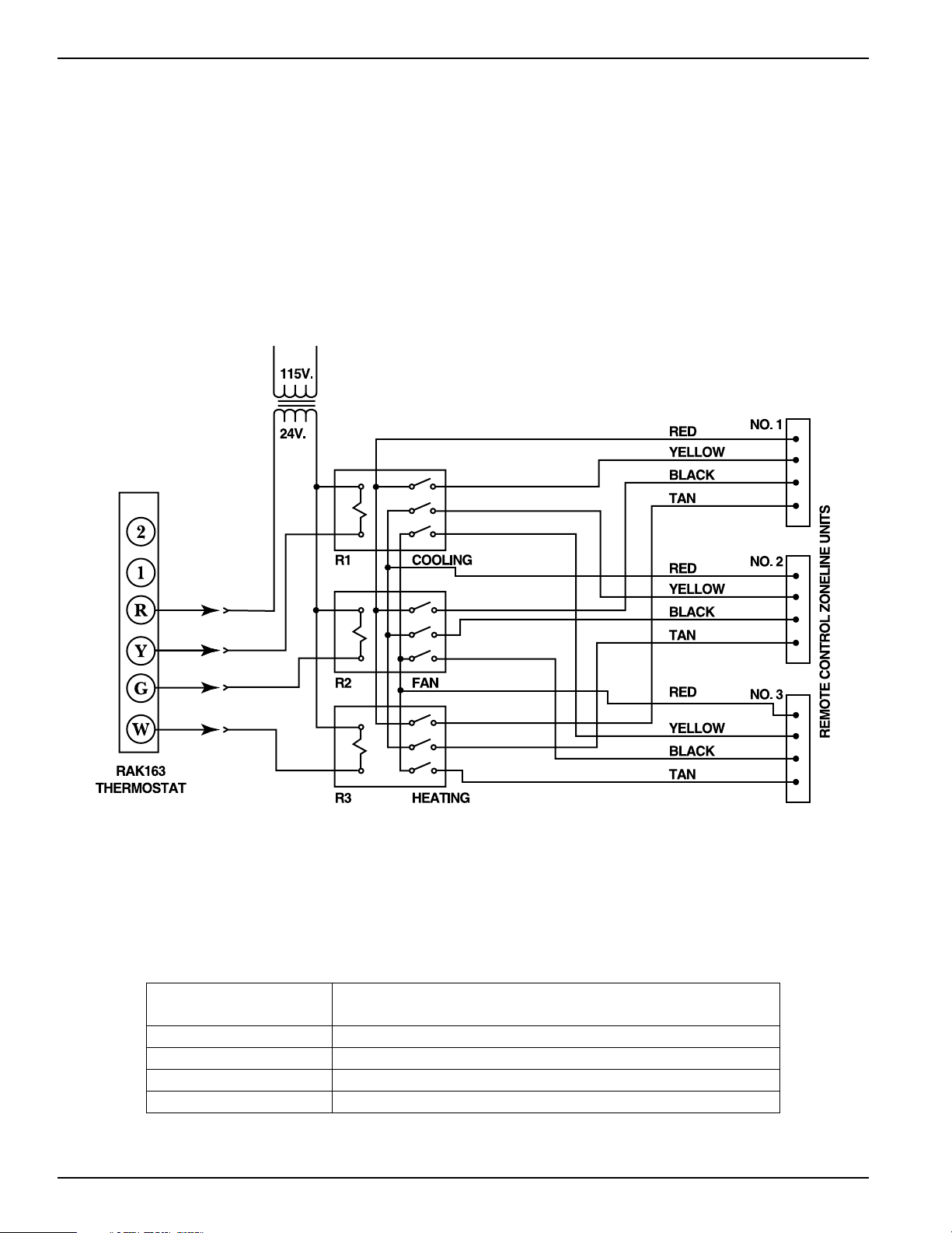
Remote Control (Low Voltage) Wiring
One stage Thermostat Controlling Three Zoneline Units
Resistance Heat Zoneline 2500 Series Units
(Not Applicable on Heat Pump Units)
Remote Thermostat Control
Multiple Units Connected to One Remote
Thermostat (2500 Series)
One remote control thermostat may be used to control
multiple resistance heat Zoneline units, however the units
may not be wired direct. Since each Zoneline unit has an
integral transformer, direct wiring can result in a “bucking”
or “boosting” voltage condition, and is in violation of the
National Electric Code. The diagram below shows the
correct wiring for such an installation through the use of
field supplied isolation relays.
For Use With Mechanical 4-Wire Systems Only
2020 Data Manual 2002 11/7/02 3:19 PM Page 18
Loading ...
Loading ...
Loading ...