Loading ...
Loading ...
1
• BEFORE attempting to install, operate or maintain the operator,
you must read and fully understand this manual and follow all
safety instructions.
• DO NOT attempt repair or service of your gate operator unless
you are an Authorized Service Technician.
When you see these Safety Symbols and Signal Words on the
following pages, they will alert you to the possibility of SERIOUS
INJURY or DEATH if you do not comply with the warnings that
accompany them. The hazard may come from something
mechanical or from electric shock. Read the warnings carefully.
When you see this Signal Word on the following pages, it will
alert you to the possibility of damage to your gate and/or the gate
operator if you do not comply with the cautionary statements that
accompany it. Read them carefully.
IMPORTANT NOTE
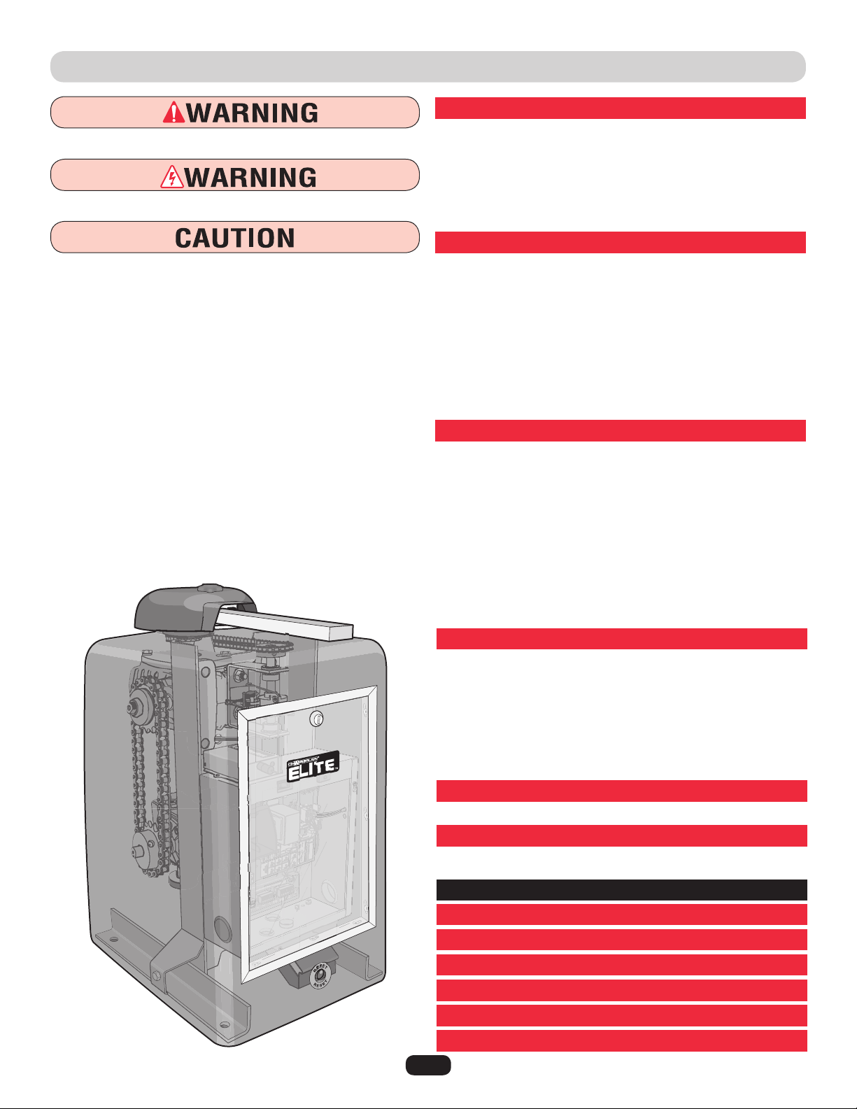
SPECIFICATIONS AND WARNINGS
Overview and Specifications ............................ 2
Model Classification .................................. 3
Safety Installation Information .......................... 4
Gate Construction Information .......................... 5
Suggested Entrapment Protection Device Locations ........6-7
Safety Precautions ................................... 8
INSTALLATION
Installation Setups ................................... 9
Concrete Pad and Arm Attachment...................... 10
Standard Installation Layout ........................... 11
Compact Installation Layout ........................... 12
Uphill Driveway Post Mounting Plate Installation .......... 13
Gate Arm Installation ................................ 14
Output Shaft Adjustment ............................. 14
Control Board Description ............................ 15
Surge Suppressor Terminal Connections ................. 16
WIRING
Earth Ground Rod Installation ......................... 17
110Vac Power Connection ............................ 18
Heater Power Connection ............................. 18
Linking Master/Second Operators ...................... 19
Solenoid/Maglock Connections......................... 20
DC2000 Back-Up Connections .......................21-22
Plug-In Loop Detector Wiring.......................... 23
110Vac External Loop Detector Wiring ................... 24
Entrapment Protection Devices (Edge Sensors) ............ 25
Entrapment Protection Devices (Non-Contact Sensors) ...... 26
ADJUSTMENTS
Set Gate Opening Direction............................ 27
Limit Switch Adjustments............................. 28
Clutch Adjustment .................................. 28
Radio Receiver Programming........................29-30
Setting the Timer (On, Off) ............................ 31
Adjusting Reversing Sensor(s) ......................... 32
OmniControl™ Board Connections ...................... 33
MAINTENANCE AND OPERATION
Maintenance ....................................... 34
OPERATION
Built-In Reset Switch ................................ 35
Audio Alarm ....................................... 35
EMERGENCY MANUAL RELEASE
................... 36
WIRING DIAGRAMS AND SPEC TABLES
.........37-42
TROUBLESHOOTING
...........................43-44
REPAIR PARTS
................................45-46
ACCESSORIES
................................... 47
INSTALLATION CHECKLIST
....................... 51
WARRANTY POLICY
.............................. 52
TABLE OF CONTENTS
Mechanical
Electrical
Loading ...
Loading ...
Loading ...