Loading ...
Loading ...
Loading ...
11
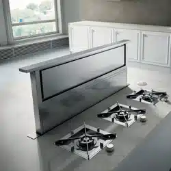
6. Drill 2 pilot holes through each of the undercounter mounting
brackets into the underside of the countertop. Using
2 - 4.5 x 13 mm screws, mount the brackets to the countertop.
IMPORTANT: Select a screw length that will not allow the screws to
go through the countertop when tightened.
A
B
C
A. Screws
B. Backsplash
C. Countertop
7. Check that the downdraft vent is level vertically. Loosen the lower
support legs screws and position the legs against the cabinet
oor.
8. Fasten the lower support legs to the cabinet oor with 2 - 4.5 x 13
screws (on each leg).
9. Tighten the lower support legs screws.
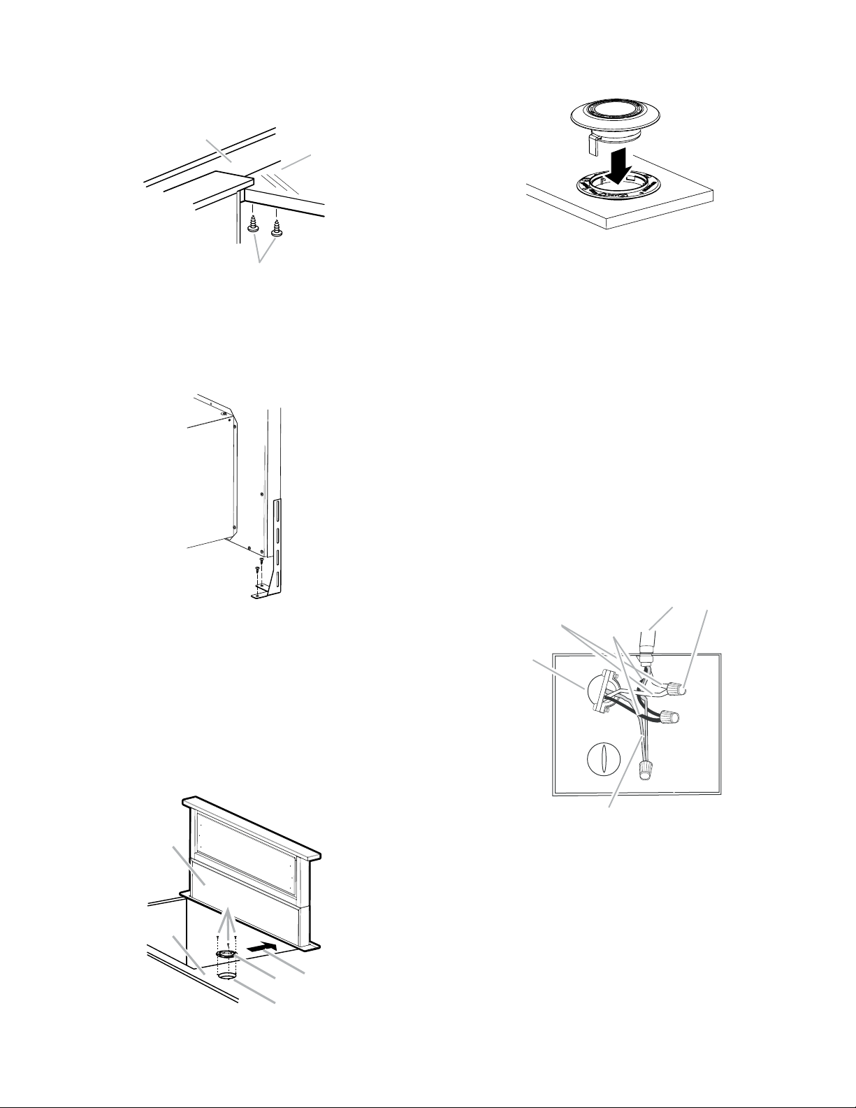
Control Installation
• Before the control installation, make sure you have made the
cutouts to proceed (see “Countertop Dimensions Chart”).
• Place the control base on location and mark the holes with a
pencil.
• Drill on the marked locations.
• Place the control base on the countertop and drive
3 - 4.5 x 13 mm installation screws.
NOTE: The legend “Front” is writen on the control base. This legend
always must be oriented to the hood’s front (F).
A
B
C
D
E
F
A. Countertop
B. Control cutout
C. Control base
D. Mounting screws
E. Hood’s front
F. Control base installation
• Run the control cable through the countertop hole.
• Push down the control assembly against the control base, until
you hear the click.
Electrical connection
WARNING
Electrical Shock Hazard
Disconnect power before servicing.
Replace all parts and panels before operating.
Failure to do so can result in death or electrical shock.
1. Disconnect power.
2. Feed the power supply cable through the conduit connector
and into the terminal box.
WARNING
Electrical Shock Hazard
Electrically ground blower.
Connect ground wire to green and yellow ground wire in terminal
box.
Failure to do so can result in death or electrical shock.
3. Connect the green (or green/yellow) ground wire to the green
or yellow/green ground wire using UL listed wire connectors.
4. Tighten the screw on the conduit connector.
5. Connect the 2 white wires together using UL listed wire
connectors.
A
D
B
F C
E
A. Green or green and yellow ground wire
B.White wires
C. UL listed wire connectors
D. Black wires
E. UL listed or CSA approved conduit connector
F. Downdraft vent wiring
Loading ...
Loading ...
Loading ...