3-Way
Smart Wall Switch
Installation Guide
3-Wire Smart Switches & Dimmers

WARNING: RISK OF ELECTRIC SHOCK
This product installation requires handling 120 volt wiring.
Follow each step carefully.
If any concerns handling wiring, hire a qualified electrician.
Ensure all work meets applicable local and national codes.
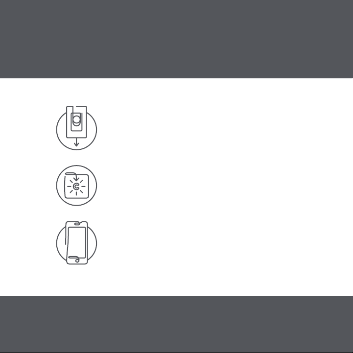
Simple DIY Set Up
STEP 1
Install your Smart Switches
STEP 2
Download the Cync App, powered by Savant,
on your smartphone
STEP 3
Add your Smart Switches to the Cync App
For set up help, visit gelighting.com/cync
GE and C by GE are trademarks of General Electric Company. Used under trademark license.
Amazon, Alexa, and all related logos are trademarks of Amazon.com, Inc. or its affiliates.
Google and other related marks and logos are trademarks of Google LLC.
WARNING: RISK OF ELECTRIC SHOCK
This product installation requires handling 120 volt wiring.
Follow each step carefully.
If any concerns handling wiring, hire a qualified electrician.
Ensure all work meets applicable local and national codes.
Simple DIY Set Up
STEP 1
Install your Smart Switches
STEP 2
Download the Cync App, powered by Savant,
on your smartphone
STEP 3
Add your Smart Switches to the Cync App
For set up help, visit gelighting.com/cync
GE and C by GE are trademarks of General Electric Company. Used under trademark license.
Amazon, Alexa, and all related logos are trademarks of Amazon.com, Inc. or its affiliates.
Google and other related marks and logos are trademarks of Google LLC.

Compatibility Requirements
Rating 120V AC 60Hz
Neutral wire is not required
(Wire is usually white or grey and
is not required)
Ground wire is required
(Wire is usually green, green with
a yellow stripe, or copper)
Wi-Fi 802.11 b/g/n @ 2.4 GHZ is
required
Works with halogen,
incandescent, and LED bulbs,
including C by GE and Cync
Smart Bulbs
Not for use with ceiling fans
LED up to 150 Watts
Incandescent/halogen up to
450 Watts
Minimum Load 15 Watts
If you are using less than 15
Watts, non-dimmable LED bulbs,
or C by GE and Cync Smart
Bulbs on the circuit, you will need
to use the included Bulb Adaptor
Use the optional Fixture Adaptor
(available separately) where the
Bulb Adaptor will not fit.
Contact Customer Support at
1-844-302-2943 for details.
Visit gelighting.com/cync for 3-way installation
instructions and how-to videos.
12
6
39
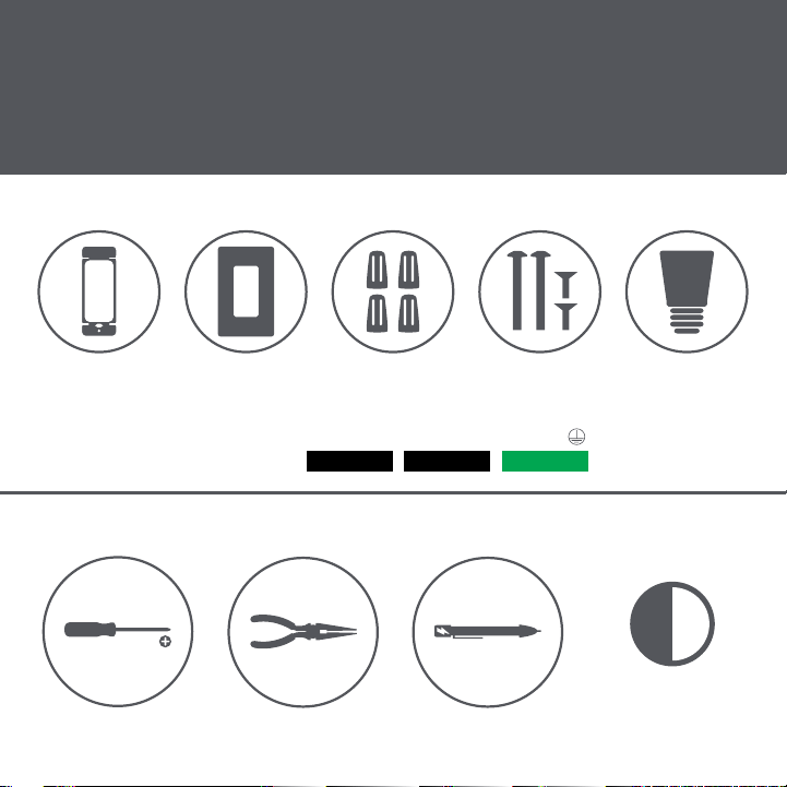
Let’s Do It
INCLUDED
YOU’LL NEED
Needle Nose Pliers
(recommended)
Voltage Tester
(recommended)
Approximately 30
minutes of your day
to install and set up
the switch
Phillips Screwdriver
Line/Load Line/Load Ground
Wire Labels
Switch Wall Plate 4 Wire Nuts 4 Phillips
Mounting Screws
Bulb Adaptor
Compatibility Requirements
Rating 120V AC 60Hz
Neutral wire is not required
(Wire is usually white or grey and
is not required)
Ground wire is required
(Wire is usually green, green with
a yellow stripe, or copper)
Wi-Fi 802.11 b/g/n @ 2.4 GHZ is
required
Works with halogen,
incandescent, and LED bulbs,
including C by GE and Cync
Smart Bulbs
Not for use with ceiling fans
LED up to 150 Watts
Incandescent/halogen up to
450 Watts
Minimum Load 15 Watts
If you are using less than 15
Watts, non-dimmable LED bulbs,
or C by GE and Cync Smart
Bulbs on the circuit, you will need
to use the included Bulb Adaptor
Use the optional Fixture Adaptor
(available separately) where the
Bulb Adaptor will not fit.
Contact Customer Support at
1-844-302-2943 for details.
Visit gelighting.com/cync for 3-way installation
instructions and how-to videos.
12
6
39
Let’s Do It
INCLUDED
YOU’LL NEED
Needle Nose Pliers
(recommended)
Voltage Tester
(recommended)
Approximately 30
minutes of your day
to install and set up
the switch
Phillips Screwdriver
Line/Load Line/Load Ground
Wire Labels
Switch Wall Plate 4 Wire Nuts 4 Phillips
Mounting Screws
Bulb Adaptor

You Got This!
And we’re here to help.
For in-depth instructional videos and
a guided tour through the installation,
go to gelighting.com/cync.
NOTE: Please make sure your system is up-to-date, and you
update the firmware when prompted for the best experience.
Installing C by GE or Cync Smart Switches on a 3-Way or Multi-Way circuit
requires ALL switches on the same circuit to be a C by GE or Cync Smart
Switch. 3-Way circuits can vary depending on the method used at the
time the home was wired.
These instructions are based on the most commonly used method.
If your wiring does not line up with these instructions, we recommend
contacting Customer Service before removing wires from the existing
switch. Although our team is trained to help with these installs, there are
some situations that could require help from a licensed electrician. For
the best result when calling support, be prepared to provide the customer
service team with photos of the wiring so the switch terminals and wires
can be identified.
NOTE: When installing 3-Wire Switches or Dimmers, your traveler wires
can be used interchangeably. In this example, we’ll use the red traveler
with line and the black traveler with load.
BEFORE YOU DO ANYTHING!
Turn Off the Power!
STEP 1
Turn off the power for the switch
location at the circuit breaker box.
STEP 2
Remove wall plates and mounting
screws for both switches you are
replacing.
STEP 3
Gently pull switches out from their
boxes so wiring can be viewed.
STEP 4
Test the wires with a voltage tester to
ensure power is off. If multiple switches
are in the same box, test them as well.
Additional breakers may need to be
turned off.
ON OFF
Check for Compatible Wiring
STEP 1
Do not disconnect any wires at this
stage. We recommend taking a picture
of your wiring before proceeding for
future reference.
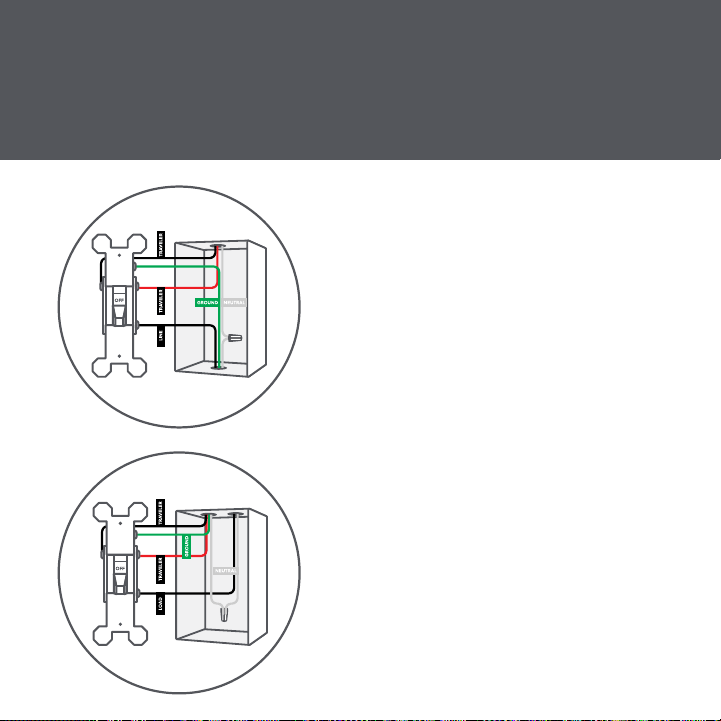
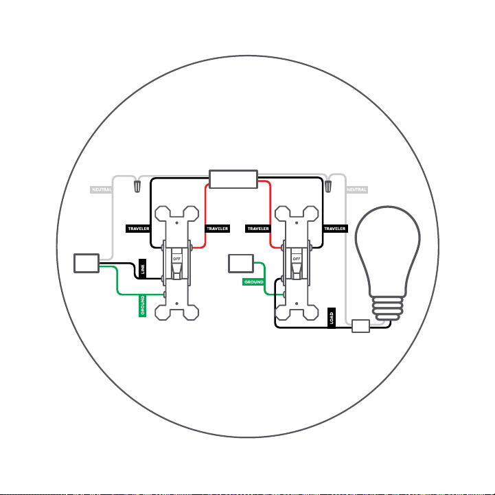
STEP 2
Wiring colors may vary. In this
diagram, ground is green. The red
and black wires connected to brass
terminals are traveler wires. The wires
connected to the black (common)
terminals are the line and load (we’ll
identify which one is which in “Identify
the Line and the Load”).
STEP 3
If all necessary wiring is present, you
can proceed with the installation.
Wiring should look similar to images
pictured left.
BEFORE YOU DO ANYTHING!
Turn Off the Power!
STEP 1
Turn off the power for the switch
location at the circuit breaker box.
STEP 2
Remove wall plates and mounting
screws for both switches you are
replacing.
STEP 3
Gently pull switches out from their
boxes so wiring can be viewed.
STEP 4
Test the wires with a voltage tester to
ensure power is off. If multiple switches
are in the same box, test them as well.
Additional breakers may need to be
turned off.
ON OFF
Check for Compatible Wiring
STEP 1
Do not disconnect any wires at this
stage. We recommend taking a picture
of your wiring before proceeding for
future reference.
STEP 2
Wiring colors may vary. In this
diagram, ground is green. The red
and black wires connected to brass
terminals are traveler wires. The wires
connected to the black (common)
terminals are the line and load (we’ll
identify which one is which in “Identify
the Line and the Load”).
STEP 3
If all necessary wiring is present, you
can proceed with the installation.
Wiring should look similar to images
pictured left.
Restore Power
STEP 1
Restore power to the switches at the
circuit breaker box.
STEP 2
Because the wires are now
disconnected and exposed, be careful
not to touch the wires with anything
but a voltage tester.
ON OFF
Identify the LINE and LOAD
STEP 1
Make sure that the light is off. Then, check the black
common terminals on both switches using a voltage tester.
One of them should test positive for voltage, and the other
one should not.
Wire that has voltage = LINE
Wire that doesn’t have voltage = LOAD
The wire box that houses your line wire will be your line side
box/switch, while the box that houses your load wire will be
your load side box/switch.
BEFORE YOU CONTINUE!
TURN OFF THE POWER!
Turn off the power for the switch location at
the circuit breaker box.
ON OFF
Stop!
What type of bulbs do you plan to use?
You may need to install a Bulb Adaptor
Some installations require the included Bulb Adaptor to maintain Wi-Fi
connectivity and to ensure your switch and bulbs work together.
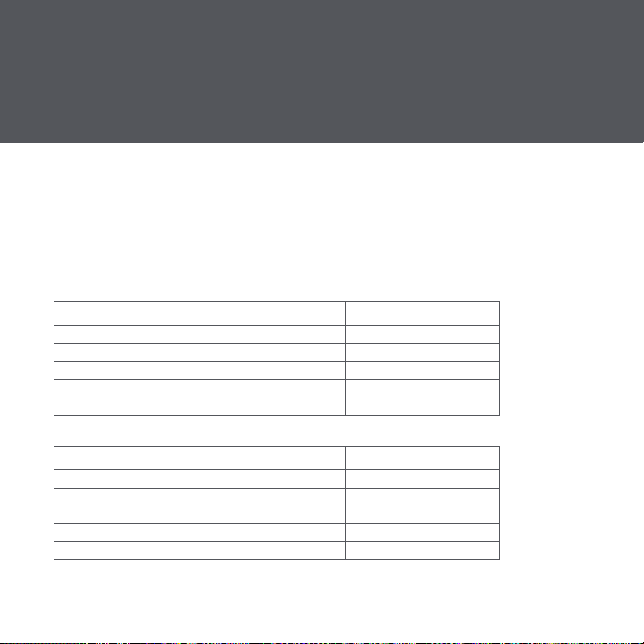
If your switch circuit includes a load of at least 15 Watts:
TYPE OF LIGHT BULB IS AN ADAPTOR REQUIRED?
Incandescent/Halogen No
Dimmable LEDs No
Non-Dimmable LEDs Yes
Cync or C by GE smart lights Yes
Combination of bulbs listed above Yes
If your switch circuit does NOT include a load of at least 15 Watts:
TYPE OF LIGHT BULB IS AN ADAPTOR REQUIRED?
Incandescent/Halogen Yes
Dimmable LEDs Yes
Non-Dimmable LEDs Yes
Cync or C by GE smart lights Yes
Combination of bulbs listed above Yes
If the Bulb Adaptor does not fit your bulb or fixture, you have other options:
• Replace your lights with incandescent, halogen, or dimmable LED light
bulbs that meet the 15 Watt minimum load requirement. See a list of
compatible bulbs at gelighting.com/cync
• Install our Fixture Adaptor to the actual fixture in the ceiling. For install
instructions and where to get a C by GE or Cync Fixture Adaptor
(available separately), contact Customer Support at 1-844-302-2943
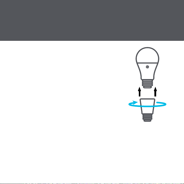
STEP 1
Twist the Bulb Adaptor onto the base of the
medium-base (E26) light bulb.
STEP 2
Screw the bulb and Adaptor into the fixture.
NOTE: Only one Bulb Adaptor is needed per
switch, even if there are multiple light bulbs
on the circuit. If installing in a recessed can
application, you may need to adjust the
recessed can depth to ensure the bulb is flush.
Installing the Bulb Adaptor
Stop!
What type of bulbs do you plan to use?
You may need to install a Bulb Adaptor
Some installations require the included Bulb Adaptor to maintain Wi-Fi
connectivity and to ensure your switch and bulbs work together.
If your switch circuit includes a load of at least 15 Watts:
TYPE OF LIGHT BULB IS AN ADAPTOR REQUIRED?
Incandescent/Halogen No
Dimmable LEDs No
Non-Dimmable LEDs Yes
Cync or C by GE smart lights Yes
Combination of bulbs listed above Yes
If your switch circuit does NOT include a load of at least 15 Watts:
TYPE OF LIGHT BULB IS AN ADAPTOR REQUIRED?
Incandescent/Halogen Yes
Dimmable LEDs Yes
Non-Dimmable LEDs Yes
Cync or C by GE smart lights Yes
Combination of bulbs listed above Yes
If the Bulb Adaptor does not fit your bulb or fixture, you have other options:
• Replace your lights with incandescent, halogen, or dimmable LED light
bulbs that meet the 15 Watt minimum load requirement. See a list of
compatible bulbs at gelighting.com/cync
• Install our Fixture Adaptor to the actual fixture in the ceiling. For install
instructions and where to get a C by GE or Cync Fixture Adaptor
(available separately), contact Customer Support at 1-844-302-2943
STEP 1
Twist the Bulb Adaptor onto the base of the
medium-base (E26) light bulb.
STEP 2
Screw the bulb and Adaptor into the fixture.
NOTE: Only one Bulb Adaptor is needed per
switch, even if there are multiple light bulbs
on the circuit. If installing in a recessed can
application, you may need to adjust the
recessed can depth to ensure the bulb is flush.
Installing the Bulb Adaptor

Identify and Label Wires
Before disconnecting the wires from the switch, identify each wire and use
the provided labels as needed.
Line: Based on “Identify the Line and the Load,” label the LINE wire that
did test positive for voltage.
Load: Based on “Identify the Line and the Load,” label the LOAD wire that
did not test positive for voltage.
Neutral: Standard switches do not require them, but the neutral wires
may be present in the box. C by GE or Cync 3-Wire Smart Switches and
Dimmers do not require neutral wires to operate. If neutral wires are
present in the junction box, cap the neutral wires and do not connect to
the C by GE or Cync Smart Switches or Dimmers.
Ground: These are usually an individual or a group of bare copper or
green wires that are sometimes connected to the green ground terminal of
the original switch. If not connected to the original switch, they should be
in the back of the box.
Travelers: The traveler wires are connected to the brass screws on the
original switches. These wires are in the same sheathed cable and should
be different colors that can vary between black, white, or red. One of these
wires will be used to provide power to the C by GE or Cync Smart Switch
on the load side of the circuit. C by GE or Cync 3-Wire Smart Switches
require both travelers to be used.

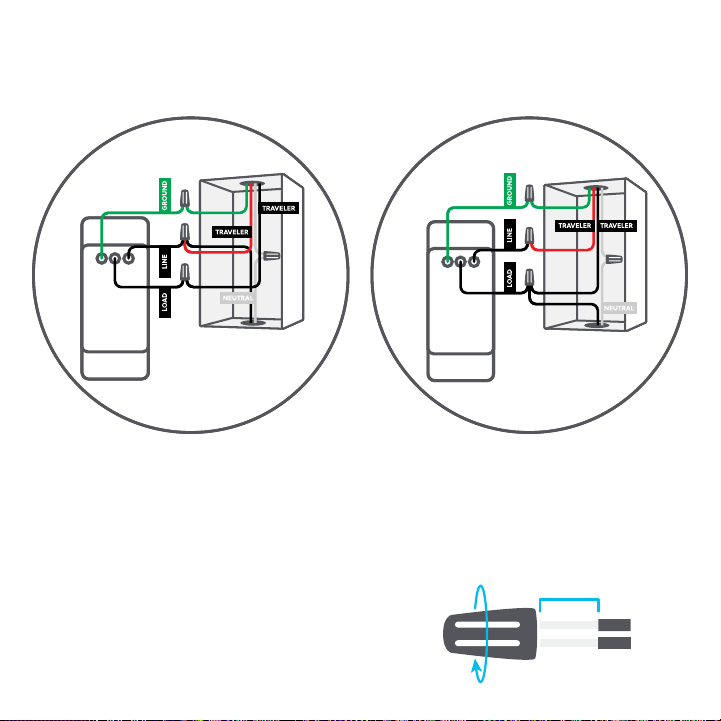
Install the Smart Switches
Line Side
STEP 1
Connect the LINE wire and one of
the TRAVELER wires from the wall
to the black LINE wire on the C by
GE or Cync Smart Switch. In this
example, we used the red traveler,
but you can use either one.
STEP 2
Connect the second remaining
TRAVELER wire from the wall to the
black LOAD wire on the C by GE or
Cync Smart Switch. For our example,
we’ll use the black traveler.
STEP 3
Connect the GROUND wire from the
wall to the green GROUND wire on
the C by GE or Cync Smart Switch.
Load Side
STEP 1
Connect the same TRAVELER you
connected to LINE on the first switch
to the LINE wire on this switch. We
used the red wire in our example.
STEP 2
Connect the LOAD wire from the
wall and the same TRAVELER that
we connected to the LOAD on
the first switch to the LOAD on this
switch. We used the black traveler
in our example.
STEP 3
Connect the GROUND wire from the
wall to the green GROUND wire on
the C by GE or Cync Smart Switch.
Line Side Load Side
Now that you have successfully identified each wire, you can disconnect
the wires and remove the original switches.
3/4 inch
USING WIRE NUTS
1. Insert wires into wire nut.
2. Turn wire nut clockwise.
3. Pull gently on wires to test connection.

Secure the Smart Switches
STEP 1
Neatly push the wires back into the boxes.
STEP 2
Using the screws provided, secure the switch to the wall
until level and flush.
STEP 3
Using the screws provided, secure the faceplate bracket.
STEP 4
Snap the faceplate cover onto the bracket.
STEP 5
Restore power to the switches at the circuit breaker box.
TROUBLESHOOTING
LED indicator light or light ring will flash blue until the switch is added
to the Cync App.
LED indicator light or light ring will not illuminate if wired incorrectly
or if the switch circuit does not meet the specified load requirements.
Important: Only the load switch will turn the light on/off until the
two Smart Switches are linked in the Cync App. The dimmer buttons
will not work on either switch until the two smart switches are linked
in the Cync App. We will handle the app set up in “Enable 3-Way
Control in the Cync App.”
If lights don’t turn on:
STEP 1
Check that power to the switch
is on at the breaker.
STEP 2
Turn power off at the breaker,
return to the switch to confirm
the wires are securely and
properly wired according to the
installation guide.
STEP 3
Go to gelighting.com/cync for
more troubleshooting.
If lights flicker, experience
intermittent power loss, or
won’t completely turn off:
STEP 1
Be sure to select the correct
bulb type in the Cync App.
STEP 2
Your installation may require
a Bulb/Fixture Adaptor or
a different bulb type. See
pages 9-10 for more details or
visit gelighting.com/cync for
troubleshooting help.

Enable 3-Way Control in the Cync App
NOTE: Only the load switch will turn the light on/off until the two Smart
Switches are linked in the Cync App. Dimmer mode can be enabled
during setup.
STEP 1
Download the Cync App.
STEP 2
Add the devices to the Cync App, following all instructions given during setup.
STEP 3
Add both Smart Switches to the same Room and/or Group in the Cync
App. They must be placed in the same Room to enable three-way control.
STEP 4
The light ring for each switch should change from flashing blue to
solid white when setup has successfully completed, and the switch is
connected via Wi-Fi.
STEP 4
Test that your 3-Way Smart Switches operate correctly.
Need assistance? Call Customer Support 1-844-302-2943.
Additional Information and Warnings
FCC Compliance Statement Compliance Notice:
This equipment has been tested and found to comply with the limits
for a Class B digital device, pursuant to part 15 of the FCC Rules.
These limits are designed to provide reasonable protection against
harmful interference in a residential installation. This equipment
generates, uses and can radiate radio frequency energy and, if
not installed and used in accordance with the instructions, may
cause harmful interference to radio communications. However,
there is no guarantee that interference will not occur in a particular
installation. If this equipment does cause harmful interference to
radio or television reception, which can be determined by turning
the equipment off and on, the user is encouraged to try to correct
the interference by one or more of the following measures:
• Reorient or relocate the receiving antenna.
• Increase the separation between the equipment and receiver.
• Connect the equipment into an outlet on a circuit different from
that to which the receiver is connected.
• Consult the dealer or an experienced radio/TV technician for help.

This device complies with Part 15 of the FCC Rules and Industry
Canada license-exempt RSS standard(s) Operation is subject to the
following two conditions:
1. This device may not cause interference.
2. This device must accept any interference received, including
interference that may cause undesired operation.
Changes or modifications that are not expressly approved by
the manufacturer could void the user’s authority to operate the
equipment.
RF Exposure Information:
This equipment complies with FCC radiation exposure limits
set forth for an uncontrolled environment. In order to avoid the
possibility of exceeding the FCC radio frequency exposure limits,
human proximity to the antenna shall not be less than 8 inches
during normal operation.
RF Exposure Statement:
This equipment complies with IC RSS-102 radiation exposure limits
set forth for an uncontrolled environment. This transmitter must be
installed to provide a separation distance of at least 8 inches from
all persons and must not be collocated or operating in conjuction
with any other antenna or transmitter.
For supply connections, use copper wire only rated at 75ºC
CAUTION - High Voltage - Disconnect power supply before
servicing
Operation temperature: 0-40ºC
For Control of Electronic Ballast, CFLs, LED, and LED Lamps
Type 1 Enclosure
IP20
Pollution Degree 2
Impulse Voltage: 2500V
Type 1 action
Indoor use only.

TM
Like your new Smart Switch?
Share your experience!
Leave a review where you purchased
the product.

