
Loading ...
Loading ...
Loading ...
Getting started
9
VQT3X48
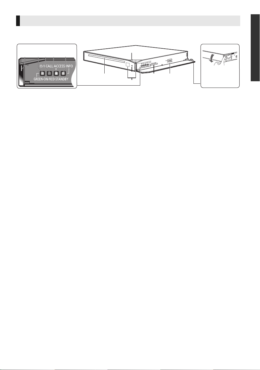
Unit
1
2
3
56
4
7891011
Pull to flip down
the panel.
Indicator LEDs
1 Standby/on switch* (Í/I) (> 16)
Touch to switch the unit from on to standby
mode or vice versa. In standby mode, the unit
is still consuming a small amount of power.
2 Disc slot (> 19)
3 Eject the disc* (> 19)
4 Remote control signal sensor
One of the two sensors will operate
depending on the installation method of the
main unit. (> 12)
Distance: Within approx. 7 m
Angle (Against front of the sensor):
Approx. 20e up and down, 30e left and right
5 SD card slot (> 19)
6 USB port (> 19)
7 Status LED (blue/red)
≥ This will light up in blue when the unit is
turned on.
≥ Blue and red will light up simultaneously
when an error occurs. (> 38)
≥ This will flash in blue when this unit
receives incoming call etc. of the video
communication. (> 25)
8 Standby/on LED (red/green)
When the unit is connected to the AC mains
supply, this indicator lights red in standby
mode and lights green when the unit is turned
on. It is also possible to set to turn off when
the unit is in standby mode. (> 37, “Standby
LED”)
9 CALL LED (blue)
The LED will light up when this unit receives
incoming call etc. of the video
communication. (> 25)
10 ACCESS LED (amber)
This will flash while accessing the SD card or
USB device.
11 INFO LED (red)
This will light up at the time of error, etc.
(> 38)
* These switches work just by touching the marks. Be
careful not to touch them unintentionally.
The volume of operation sound can be adjusted by “Unit
Operation Volume”. (> 37)
DMP-BBT01GN-VQT3X48_mst.book 9 ページ 2012年4月20日 金曜日 午後2時44分
Loading ...
Loading ...
Loading ...