
Insteon Wall Switch
Owner’s Manual
Insteon Wall Switch
Owner’s Manual

Contents
Getting Started
Insteon Wall Switch 4
Dimmer Switch & On/O Switch
High-Wattage Dimmer Switch
Tools Needed for Installation
Disconnect Power
Installation
Installation Diagrams
Standard Switch 10
Three-Way Switch 11
Four-Way Switch 12
Insteon Links
Understanding Linking 14
Linking to the Insteon Hub 16
Linking with a Single-Button Controller 17
Linking with a Multi-Button Controller 18
Multi-Linking or Making a Scene 19
Unlinking from a Single-Button Controller 20
Unlinking from a Multi-Button Controller 21
Multi-Unlinking or Removing a Scene 22
Local Programming
Factory Reset
Software-Only Features
Beep on Button Press 29
Blink on Trac
Disable Local Programming
Error Blink
LED Brightness 30
Appendix
Specications 33
Troubleshooting 36
Certications and Warnings 38
Product Warranty 39
3
Everything you need to quickly get up and running.
Getting Started
Everything you need to quickly get up and running.
Getting Started
4
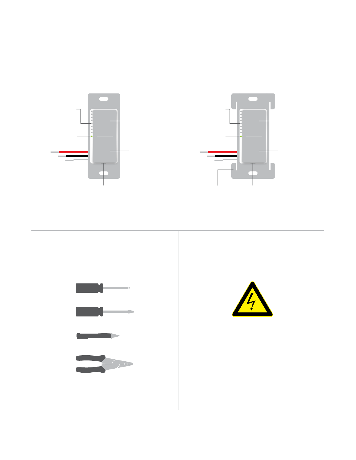
Dimmer Switch & On/O Switch High-Wattage Dimmer Switch
Insteon Wall Switch
Tools Needed for Installation Disconnect Power
Set Button Set ButtonHeat Sink Tab
(1000W Only)
O
Hold to Dim
O
Hold to Dim
On
Hold to
Brighten
On
Hold to
Brighten
Brightness
LEDs
Brightness
LEDs
Status LED Status LED
Phillips Screwdriver
Wire Cutter / Stripper
Voltage Detector
Flathead Screwdriver
Always disconnect power before
installation. Contact Insteon
Support when uncertain about
installation.
1-866-243-8022
5
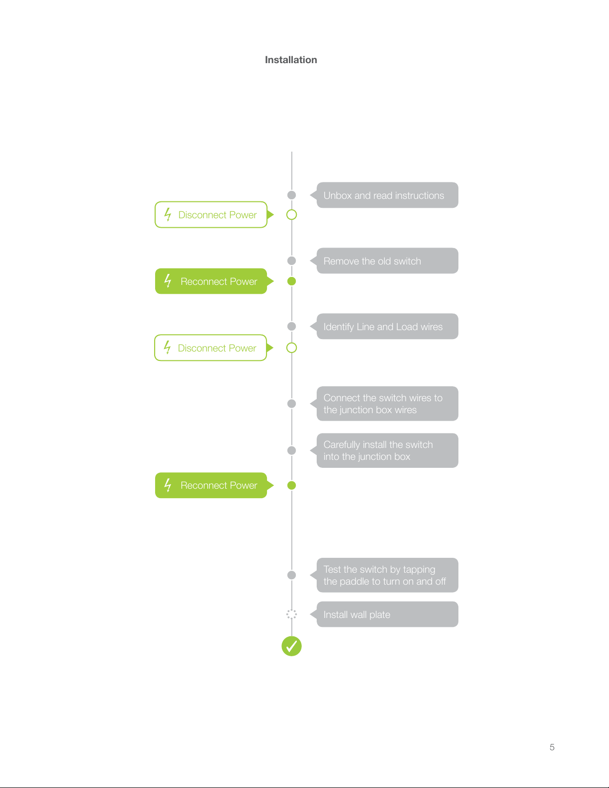
Installation
Unbox and read instructions
Remove the old switch
Identify Line and Load wires
Install wall plate
Carefully install the switch
into the junction box
Connect the switch wires to
the junction box wires
Test the switch by tapping
the paddle to turn on and o
$
RADIO
RADIO
SMOKE AND CARBON
MONOXIDE ALARM
a
1:3 0
iOS
MANUAL
INSTEON
Quick Start Guide
INSTEON
Owner’s Manual
This device complies with FCC
Rules and Industry Canada
license-exempt RSS standard(s).
Operation is subject to the
following two conditions: (1) this
device may not cause harmful
interference, and (2) this device
must accept any interference,
including interference that may
cause undesired operation of
the device.
INSTEON
Documentation
720P
BUSINESS REPLY MAIL
ATTN: INSTEON
16542 MILLIKAN AVE
IRVINE CA 92606
Disconnect Power
Reconnect Power
Disconnect Power
Reconnect Power
Installation
Unbox and read instructions
Remove the old switch
Identify Line and Load wires
Install wall plate
Connect the switch wires to
the junction box wires
Carefully install the switch
into the junction box
Test the switch by tapping
the paddle to turn on and o
$
RADIO
RADIO
SMOKE AND CARBON
MONOXIDE ALARM
a
1:3 0
iOS
MANUAL
INSTEON
Quick Start Guide
INSTEON
Owner’s Manual
This device complies with FCC
Rules and Industry Canada
license-exempt RSS standard(s).
Operation is subject to the
following two conditions: (1) this
device may not cause harmful
interference, and (2) this device
must accept any interference,
including interference that may
cause undesired operation of
the device.
This device complies with FCC
Rules and Industry Canada
license-exempt RSS standard(s).
Operation is subject to the
following two conditions: (1) this
device may not cause harmful
interference, and (2) this device
must accept any interference,
including interference that may
cause undesired operation of
the device.
INSTEON
Documentation
720P
BUSINESS REPLY MAIL
ATTN: INSTEON
16542 MILLIKAN AVE
IRVINE CA 92606
Disconnect Power
Reconnect Power
Disconnect Power
Reconnect Power
6
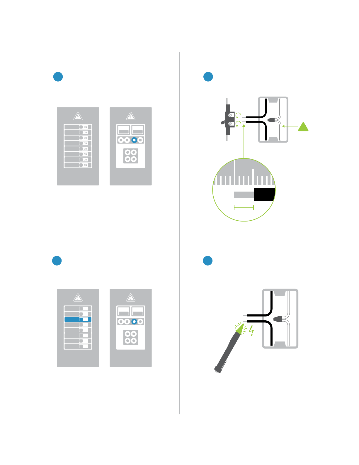
Identify Line and LoadReconnect Power
Disconnect Power Remove the Old Switch
Installation
Turn o power to your switch at the
electrical service panel.
Remove the old switch and disconnect
the wires. If your box lacks neutral
wires, stop and contact support.
Use a voltage detector or multi-meter
to identify line and load. Line will be
energized.
Turn on power at the circuit breaker.
1 2
43
ON
ON
ON
ON
ON
ON
ON
ON
ON ON
ON ON
Circuit Breakers
Circuit Breakers
Fuse Panel
Fuse Panel
or
or
Neutral
Wire
½”
12mm
1 2
!
7
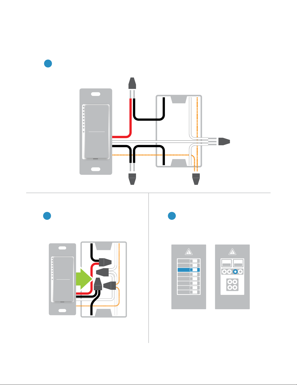
Reconnect PowerInstall the Switch
Wire-In The Switch
Installation
Turn o power at the circuit breaker. Connect the Wall Switch wires to the identied wires in the junction
box. Verify that the wire nuts are secure and that no exposed copper wire is visible except for the bare
ground wire. Additional wiring diagrams can be found in the Installation Diagrams section.
Turn power on to the switch at the circuit
breaker panel.
Mount the Wall Switch into the junction
box with the LED bar on the left.
5
76
ON
ON
ON
ON
ON
ON
ON
ON
ON ON
Circuit Breakers Fuse Panel
or
Neutral
Line
Load
Ground
8
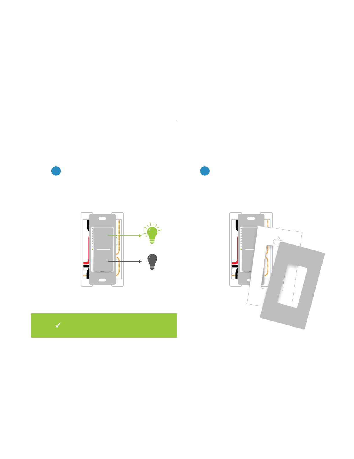
Install Wall PlateTest the Switch
Complete installation by reattaching
your wall plate. For the best look, us an
Insteon Screwless Wall Plate.
Test your Wall Switch by tapping the
paddle to turn On and O. Press and
hold to dim or brighten.
98
Installation
Installation of your Wall Switch is
now complete.
9
Use the installation diagrams in this section to help you wire your Wall
Switch, everything from straight forward, single-switch to multi-way and
beyond.
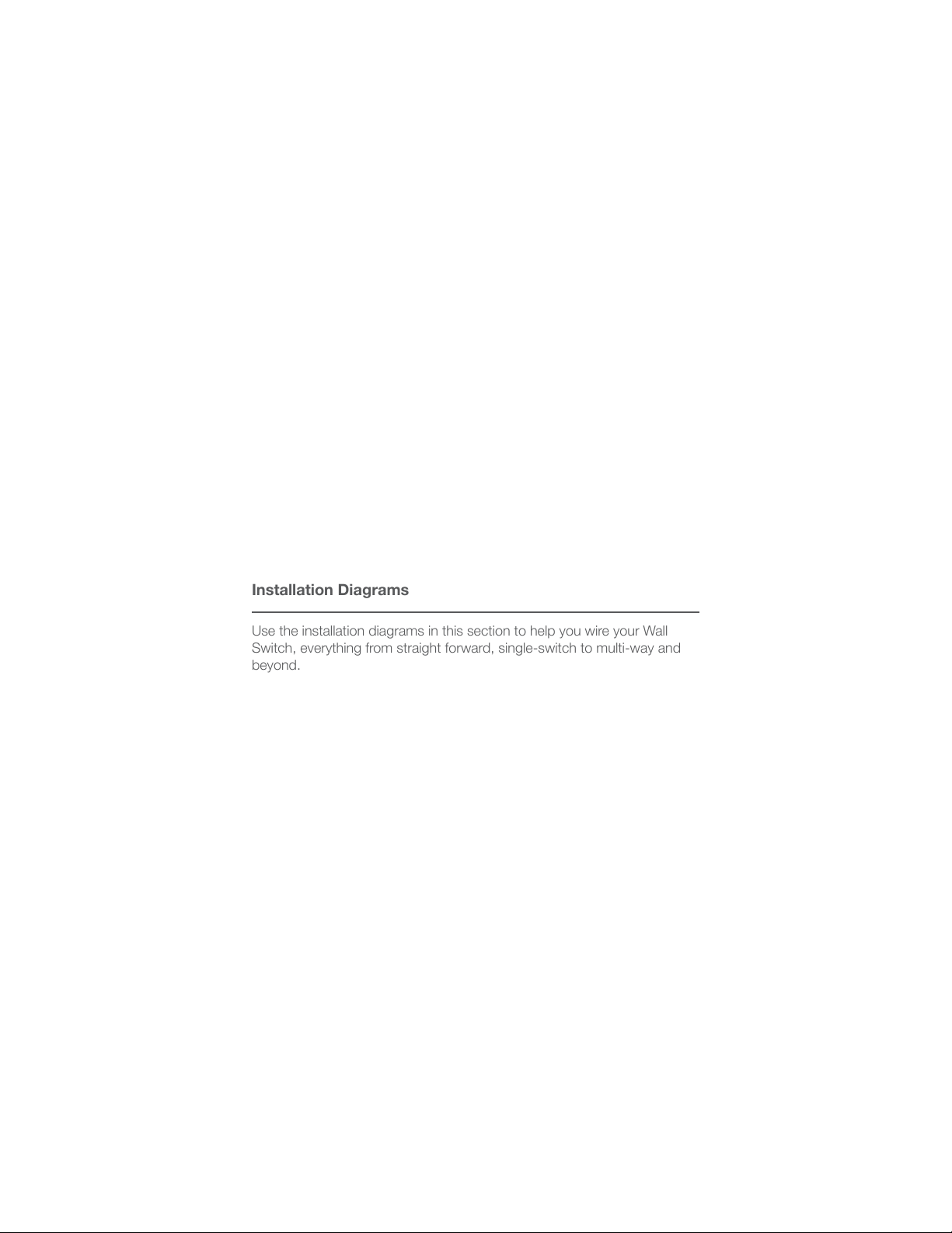
Installation Diagrams
Use the installation diagrams in this section to help you wire your Wall
Switch, everything from straight forward, single-switch to multi-way and
beyond.
Installation Diagrams
10
Standard Switch
Line Ground
Neutral
Load
11
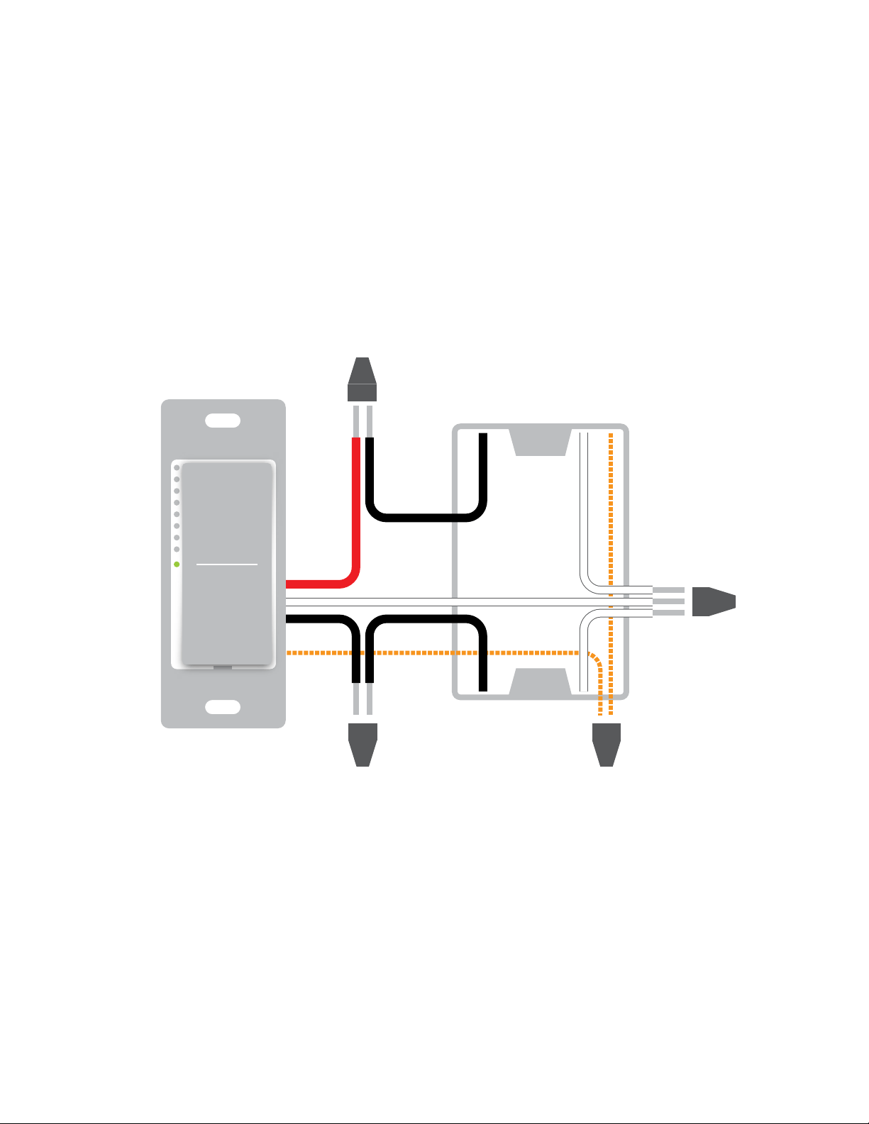
Line Ground
Neutral
Load
Not Used
LineGround
Neutral
Load
Three-Way Switch
Traveler
Not Used
12
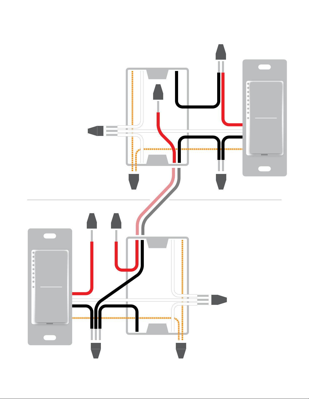
Load
Not Used
Line
Line
Ground
Ground
Neutral
Neutral
GroundLine
Netural
Load
Four-Way Switch
Traveler 2
Not Used
Traveler 1
Not Used
Load
Not Used
13
Insteon devices can stand alone and function as a local switch or dimmer,
but their real power comes when they are connected together to form a
control system. Most Insteon devices can control one another and be the
recipient of control. The process of associating multiple Insteon devices to
one another is called Linking.
Insteon Links
14
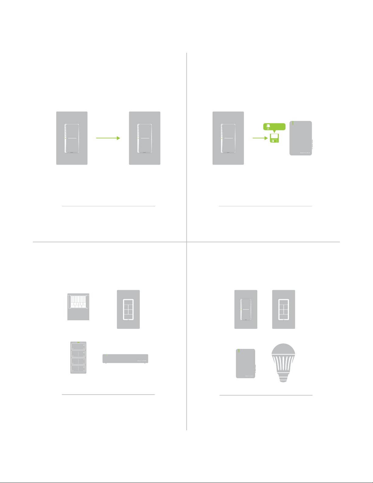
When linking Insteon devices, the links that
are created are one-way.
The current state of the controlled device is
stored in the link: On, o or dimmed.
Switch A will turn Switch B on and o but
Switch B cannot turn Switch A on or o.
The switch will turn on the Lamp Dimmer to
75% brightness.
A SwitchB Lamp Dimmer
NEW
X
NEW
X
75%
Insteon devices that can turn other devices on
or o are called controllers.
Sensors, Switches, Keypads and the
Hub are common controllers.
NEW
X
Insteon devices that receive the command of a
controller are called responders.
Switches, Keypads, Plug-In Modules and
LED Bulbs are common responders.
NEW
X
RespondersControllers
Links Remember a Device’s StateLinks are One-Way
Understanding Linking
15
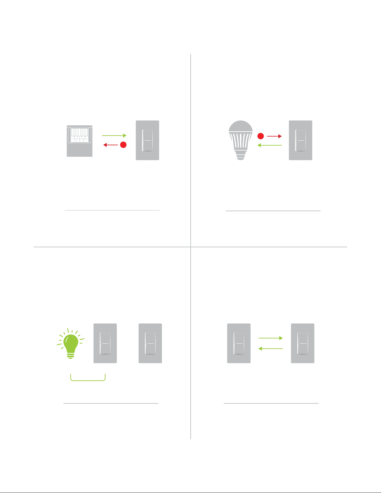
Controller-Only
Some devices, like sensors, can only control
other devices.
The Motion Sensor will turn on the Switch
but the switches cannot control the Motion
Sensor.
NEW
X
Responder-Only
Some devices cannot control other devices;
these devices only receive Insteon commands.
Some devices can only link as
responders to devices and scenes.
LED Bulb Dimmer Switch
NEW
X
X
Understanding Linking
Grouping Devices Use Cross Linking
You may want to group together two
devices, for example, in a virtual-three way
conguration. For Insteon, this is called Cross
Linking.
To Cross Link, simply turn on the devices and
perform the linking process twice, once in
each direction.
To mirror Switch A and B so that they each
control one another and the connected
load, Cross Linking is necessary.
Link Switch A to Switch B and repeat to link
Switch B to Switch A.
NEW
X
NEW
X
A BLoad
Motion Sensor
X
Dimmer Switch
A B
16
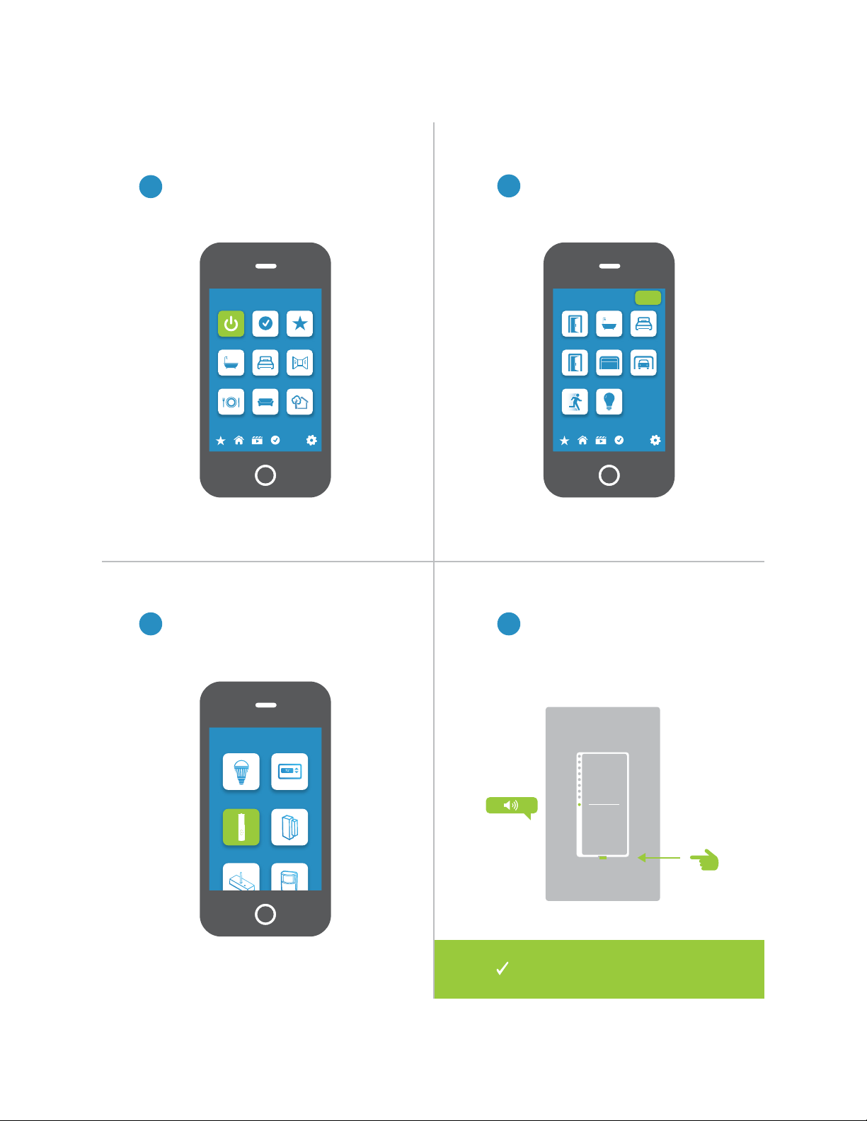
Linking to the Insteon Hub
2
Tap the Add button.
1
3 4
From Rooms, navigate to All Devices.
Select Wire-In Device from the list of
devices.
When prompted, press and hold the
set button on your Wall Switch until
the device beeps.
Rooms
All Devices Check-In Favorites
Bathroom Bedroom Hallway
Kitchen Living Room Outside
72º
Add Device
LED Bulb Thermostat
Door Sensor
Open/Close
Sensor
All Devices
Back Door Bathroom Bedroom
Font Door Garage Door Garage Light
Motion Sensor Outside Lights
72º
Add
Your Wall Switch is now added
to your Insteon Hub.
17
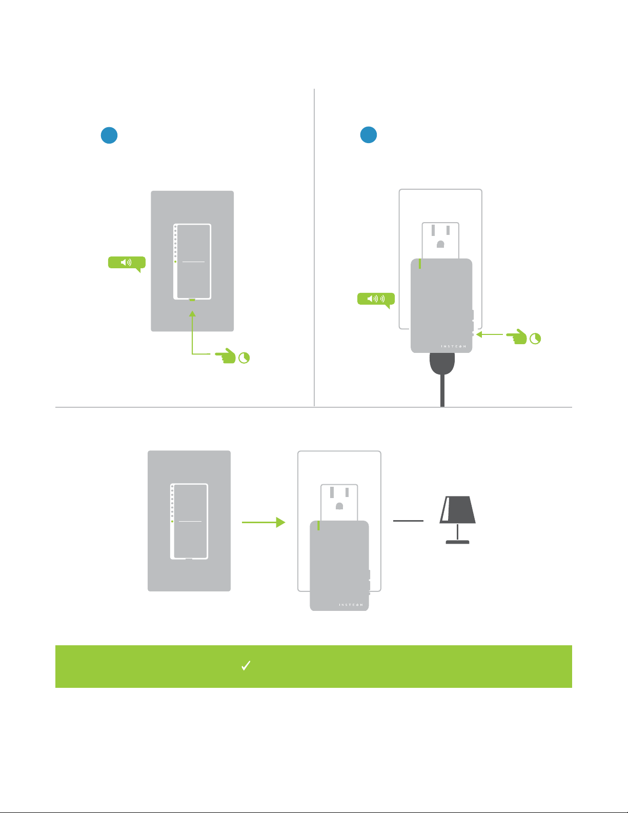
Linking with a Single-Button Controller
2
Adjust your responder to the desired
state: On, o, or brightness level if
dimming, and then press and hold the
set button until the device double-beeps.
1
On your Insteon Wall Switch, press
and hold the set button until the
device beeps.
®
®
Your Insteon Wall Switch will now
control your Insteon device.
18
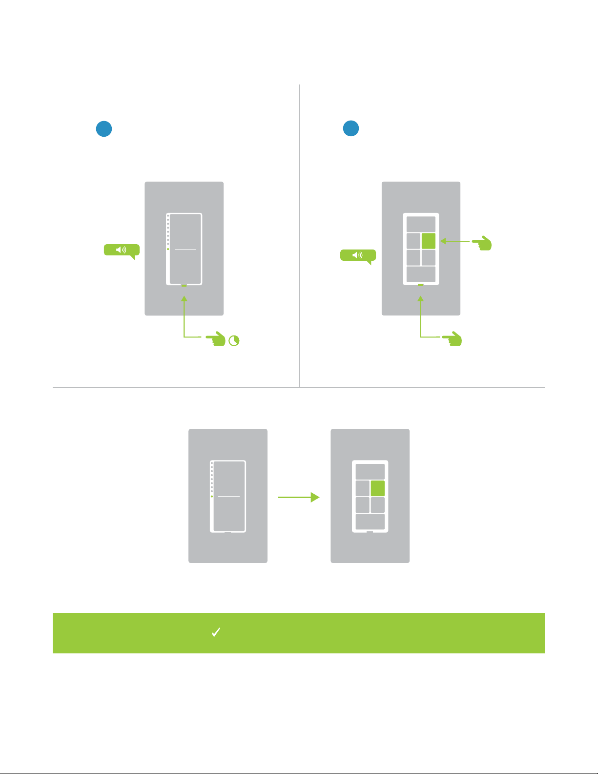
Your Wall Switch will now control a button
on your multi-button Insteon device.
A
B
Linking with a Multi-Button Controller
2
On your multi-button Insteon
device, tap the desired button and
then press and hold the set button
until the device beeps.
1
Press and hold the set button on
your Wall Switch.
19
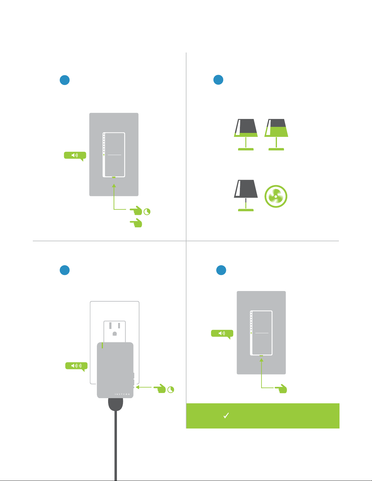
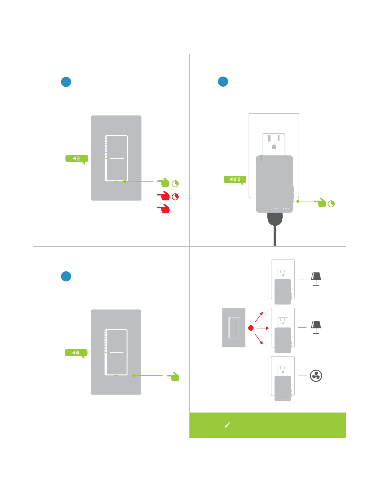
Multi-Linking or Making a Scene
2
3 4
Adjust the devices in your scene
to their desired state: on, o, or
brightness level if dimming.
Lamp 1
Lamp 3
Lamp 2
Appliance
One at a time, press and hold the
set button on each device in the
scene until it double-beeps.
Tap the set button on your Wall
Switch to nish building your scene.
1
On your Insteon Wall Switch, press
and hold the set button until the
device beeps, then tap the set
button.
50% 72%
30%
ON
®
A
B
Your Wall Switch will now
control your scene.

20
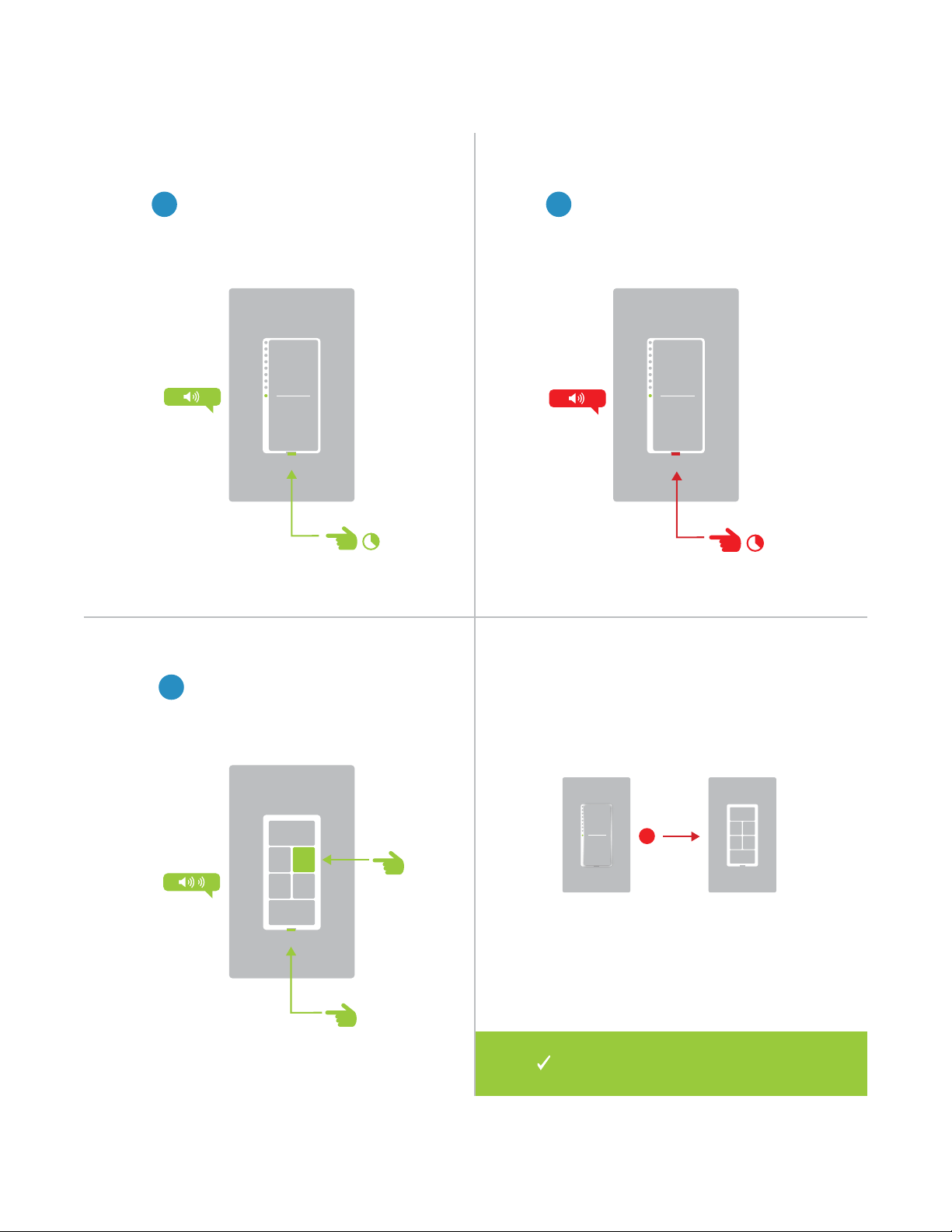
Unlinking from a Single-Button Controller
1
On your Insteon Wall Switch, press
and hold the set button until the
device beeps.
2
Press and hold the set button
again until the device beeps.
3
Press and hold the controlled
device’s set button until the device
double-beeps.
®
®
X
Your Wall Switch will no longer
control your Insteon device.
21
A
B
1
On your Insteon Wall Switch, press
and hold the set button until the
device beeps.
Unlinking from a Multi-Button Controller
2
Press and hold the set button
again until the device beeps.
3
On your multi-button Insteon
device, tap the desired button and
then press and hold the set button
until the device double-beeps.
X
Your Wall Switch will no longer control
your multi-button Insteon device.
22
Multi-Unlinking or Removing a Scene
2
3
One at a time, press and hold the
set button on each device in your
scene until it double-beeps.
Tap the set button on your Wall
Switch to exit Multi-Unlinking mode.
1
On your Insteon Wall Switch, press
and hold the set button until the
device beeps. Press and hold the
set button again, then tap the set
button.
®
A
B
C
®
®
®
X
Your Wall Switch will no longer
control your scene.

23
Encompassing all on-device programming options, use the local
programming to set local properties and factory reset. For the best
experience, use software for managing device properties.
Local Programming
Encompassing all on-device programming options, use the local
programming to set local properties. For the best experience, use
software for managing device properties.
Local Programming
24
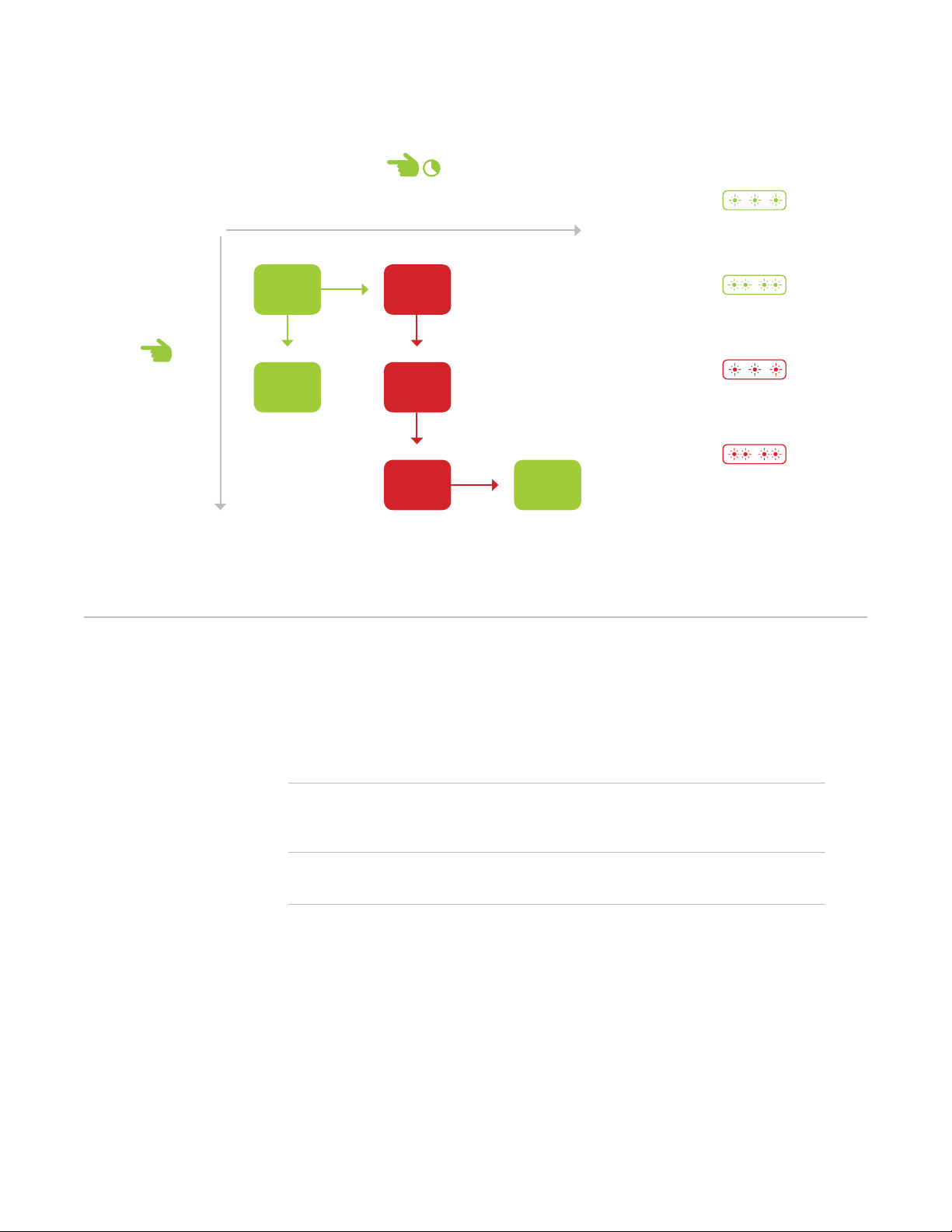
Navigating the Chart
Features
Linking Mode Readies the module for linking to another Insteon module. As linking is directional,
the rst device placed into linking mode will become the controller in the controller/
responder relationship. The second device will become the responder. The device
automatically exits linking mode after a link has been made with another Insteon device.
Multi-Linking Mode Readies the module for linking to multiple Insteon modules. The module will remain in
linking mode for 4 minutes or until the module’s set button is tapped. This mode is very
usefully for manually creating scenes.
Unlinking Mode Allows the removal of links from the Insteon module. The device will automatically exit
unlinking mode after a link has been removed from another Insteon device.
Multi-Unlinking Mode Allows the removal of multiple links from the Insteon module. The device will stay in
unlinking mode for 4 minutes or until the device’s set button is tapped.
To move right, press and
hold the set button
To move down,
tap the set button
Status LED
double-blinks red
Status LED double-
blinks green
Status LED
blinks red
Status LED
blinks green
25
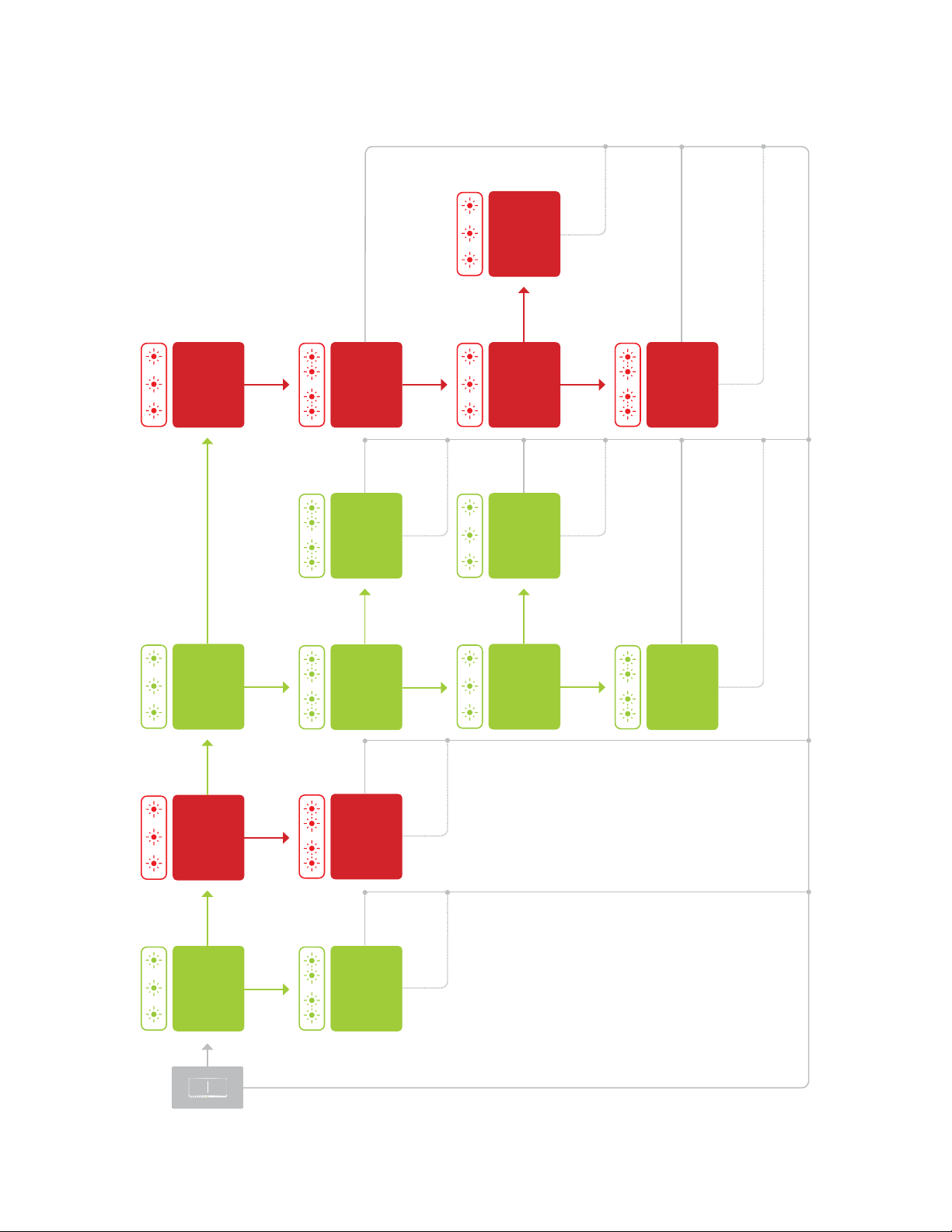
Flow Chart
Unlinking Mode
Ramp Rate
Select
Ramp Rate
Cycle through
four presets
Multi-Unlinking
Mode
Select
On Level
Uses the current
brightness
Resume Dim
Uses the current
brightness
Linking Mode
RF Beacon RF Beacon
Toggle
Multi-Linking
Mode
Select
LED Brightness
Select
LED Brightness
Adjust
Factory Reset
Select
Press
Tap
Tap
Tap
TapTap
Tap Tap
Tap
Press Press
Press Press Press
Press
PressPress
Press
Press
TapTapTap
Tap
Tap Tap
Tap
Cancel Save
Save
ExitExit
Cancel
Reset
SaveExitExit
Save
Cancel Cancel
Save
Press Press
26
A factory reset will erase all links stored in the device’s database as well as
any customized properties.
Factory Reset
A factory reset will erase all links stored in the device’s database as well as
any customized properties.
Factory Reset
27
Your Wall Switch has been
restored to factory settings.
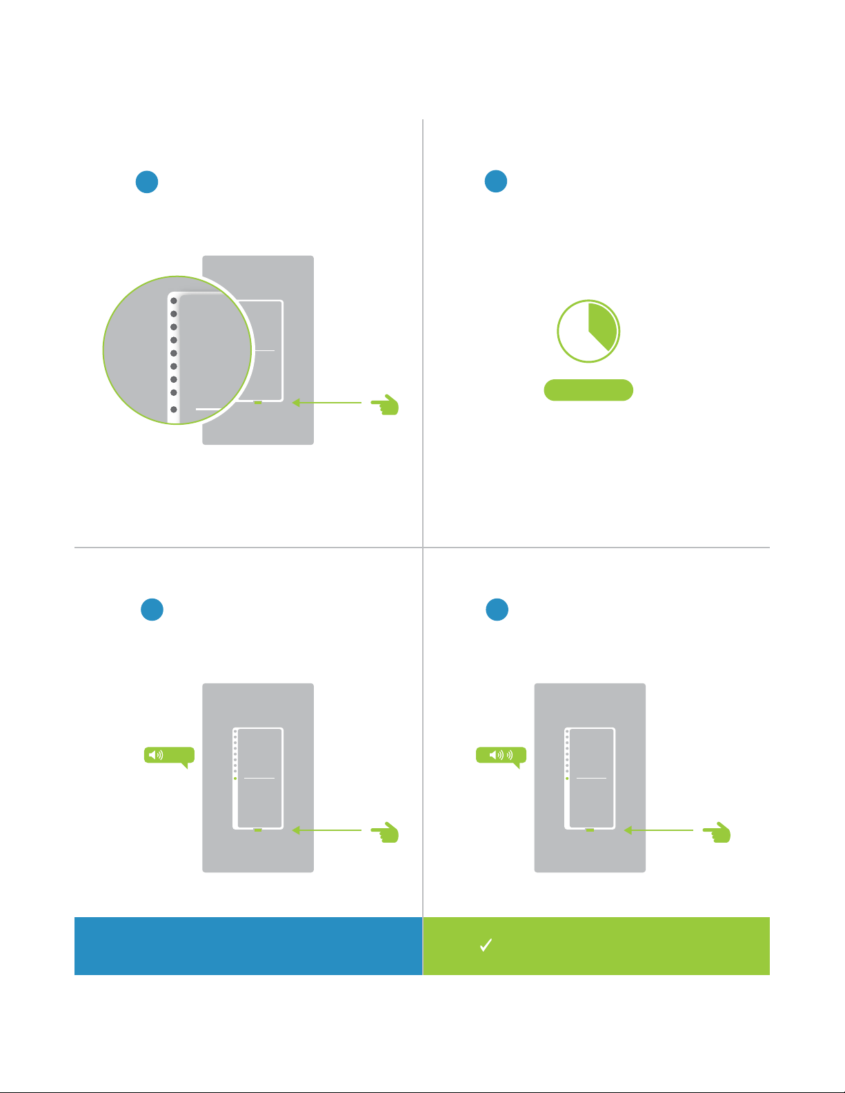
Factory Reset
1
Pull the set button out from the
switch until the status LEDs turn o.
2
Wait about ten seconds.
3 4
Push in and hold the set button
until the long beep subsides.
Release the set button. The switch
will double beep.
LONG
Press and hold for 10 seconds on
older switches that don’t long beep.
?
10 Seconds
28
Most Insteon devices contain features that can only be enabled, disabled
or modied using Insteon control software such as HouseLinc and an
Insteon PowerLine Modem.
Software-Only Features
Most Insteon devices contain features that can only be enabled, disabled
or modied using Insteon control software such as HouseLinc and an
Insteon PowerLine Modem.
Software-Only Features
29
The Wall Switch LED will blink if it detects
Insteon communication. By default, this
feature is disabled.
Prevents changing any settings using the set
button or tap-and-hold programming.
X
Software-Only Features
Beep on Button Press Blink on Trac
Disable Local Programming Error Blink
The Wall Switch LED will blink red once if one
or more responders do not acknowledge
a message and will blink green once if all
responders successfully acknowledge a
message. By default, this feature is enabled.
The Wall Switch will beep every time one of its
buttons are tapped. By default, this feature is
disabled.
X

30
Adjust the brightness of the status LEDs from
full bright to o.
LED Brightness
Software-Only Features

31
Everything else you might need to know about your Insteon product.
Appendix
Everything else you might need to know about your Insteon product.
Appendix

32
Insteon Glossary
Controller The Insteon transmitter
Responder The Insteon receiver
Blinking LED turning on and o repeatedly
Dual-Band An Insteon device that can send and receive both Insteon powerline signals and Insteon
radio frequency signals
Ramp Rate The speed at which the load fades on or o
On-Level The preset brightness level a device will return to when turned on
Insteon A dual-band, mesh networking technology developed by Smarthome/Insteon. The world’s
most reliable, expandable and simple home automation and control technology.
Link A one way association between a controller and responder
Linking A method for associating Insteon controller buttons with groups of Insteon responders such
that the responders instantly return to a memorized state when the button is pushed. Links
can be made manually with the set button or using software.
Unlinking The process by which an Insteon device can remove stored links. Just as with linking,
unlinking is a one-way process and should be performed in both directions for devices that
are both controllers and responders of each other, as in a 3-way switch scenario.
Multi-Linking
/ Unlinking
A special mode that allows more than one link to be either created or removed
simultaneously, without laborious set button presses. When in linking or unlinking mode,
an Insteon device will continue to link to other devices until the set button is tapped or four
minutes have elapsed, whichever occurs rst.
Factory Reset A process that erases all stored links and recongures the device to factory defaults.
Load The device that you are controlling (e.g. a light bulb, ceiling fan, etc.)
On/O A device that can control its connected load to turn on and o but cannot dim. Usually a
relay-based device.
Retry A 2nd (or subsequent) attempt by a controller to send an Insteon signal, usually after an
acknowledge is not received from the responder in the expected time-slot.
Scene Multiple devices respond to memorized states. For example, a dinner time scene turns
on the dining table light, dims the kitchen lights to 10%, backyard lights turn o and the
thermostat adjusts to 72º.
Set Button A button on an Insteon device that is used for setting or changing its properties
Simulcast A method for increasing the reliability of message delivery in a network. When a node in
a network sends a message, every other node that hears the message retransmits it at
precisely the same time based on a global clock, provided that the message has not already
been retransmitted some maximum number of times. Message propagation is more robust
because each node adds its energy to the signal, much like voices in a choir. Simulcasting
is much simpler than message routing because there are no routing tables to maintain and
nodes can join the network without any installation procedure.
X10 A legacy powerline networking technology. Many Insteon devices are backwards compatible
with X10 devices by setting a house and unit code.

33
Specications
General
Available Colors White
Brand Insteon
FCC ID SPB2477
Industry Canada 5202A-24772
Product Number. 2477S On/O Switch
2477D Dimmer Switch
2477DH Dimmer Switch (High Wattage)
Patent Protected under US and Freign Patents (see www.insteon.com/
patents)
UPC 813922012378 On/O Switch
689076401746 Dimmer Switch
813922011005 Dimmer Switch (High Wattage)
Warranty 2 years, limited
Operation
On-Levels 32 locally, increments of 1% with software
Ramp Rates 0.125 seconds to 8 minutes
Status LED 9 White LEDs
Operation Modes Insteon
Multi-Way Circuit Support Yes, one switch controls the load. All other switches are
secondaries.
Setup Memory Non-volatile EEPROM
Insteon Features
Insteon Addresses 400
Insteon Device Category 0x01
Insteon Device Subcategory 0x00
Insteon ID 1
Insteon Links 417
Insteon Messages Repeated Yes
Insteon Powerline Device Yes
Insteon RF Device Yes

34
Maximum Controlled Scenes 1
Maximum Scene Memberships 1
Multi-Link Support Yes
Multi-Unlink Support Yes
Phase Detect Beacon Yes
Radio Frequency 915.0 MHz US
Radio Frequency Range 150 feet
Scene Commands Supported as
Controller
On O
Fast-On Fast-O
Begin Brighten Begin Dim
End Brighten End Dim
Scene Commands Supported as
Responder
On O
Fast-On Fast-O
Begin Brighten Begin Dim
End Brighten End Dim
Software Congurable Yes
Mechanical
Paddle Type True rocker action
Wire Nuts 4 Included
Mounting Single or multi-gang junction boxes. Derating of 200W for each
immediately adjacent dimmer.
Dimensions On/O and Dimmer Switch
4.1” H x 1.8” W x 1.2” D
104mm x 46mm W x 31mm D
Dimmer Switch (High Wattage)
4.1” H x 2.5” W x 1.2” D
104mm x 64mm W x 31mm D
Operating Environment Indoors
Operating Humidity Range 0-90% relative humidity, non-condensing
Operating Temperature Range -40º to 104º F
-40º to 40º C
Specications

35
Electrical
Supply Voltage 100-277 Volts AC ± 10%, 50/60Hz, Single Phase
Neutral Wire Required
Power Wire Leads 6” 16 AWG stranded 600V
Line
Load
Neutral
Maximum Amperage 5 amps
Ground Lead 6” 18 AWG stranded bare copper
Power Consumption 0.59 Watts
Certication ETL 3017581
Specications
Set Button 1, recessed. Requires removal of sensor to access
Storage Temperature Range -40º to 104º F
-40º to 40º C
Weight 3.6 oz
102g

36
Troubleshooting
The LED lights on the Wall Switch are not illuminated
It is possible that your switch is not getting power or that the status LEDs have been disabled.
Try this:
• Check to make sure power is owing to your Insteon Wall Switch. If your switch was just installed, make
sure the circuit breaker controlling the switch has been turned on. It is also advisable to verify the wire
connections in the junction box are secure and not showing any bare wire. If any changes were made to the
xture when installing your Insteon Wall Switch, check the wire connections there, too.
• If the switch works and the connected light can be controlled, use software or the Local Programming
Flowchart to change the behavior of the status LED. The status LED brightness can be dimmed to the
point that it appears o. The Insteon Hub and other central controller software allow setting of this device
property.
Unable to add the Wall Switch to a scene as a controller or a responder
If the device has power, something is likely interfering with the Insteon signal. Large appliances, power strips and
some electronic devices may generate powerline noise.
Try this:
• Check to see if you have connected your Wall Switch downstream of a GFCI outlet. While this wiring
scenario is unlikely, GFCI outlets often unintentionally lter out the Insteon powerline signal. If testing the
GFCI outlet disconnects power to your Wall Switch, investigate alternative wiring options.
• Large appliances like refrigerators or air conditioners may be generating powerline noise that is disrupting
the Insteon signal. If the issue only appears to happen when one of these large appliances is running, install
a noise lter at that device. If you are uncertain of the device generating the noise, disconnect the potentially
oending devices from power and test your Wall Switch again. If the issue is resolved, install noise lters at
each oending appliance.
• Some small electronics devices that include an AC/DC power supply can generate substantial electrical
noise, in some cases, enough to disrupt an entire house of Insteon devices. Search your home for speaker
docks, small stereos, etc. and disconnect them from power to perform testing. If removing these devices
from your powerline resolves the Insteon issue, install a noise lter at each oending small electronic
appliance.
• Your Wall Switch may be too far from another Insteon device to receive a signal. Try locating a Range
Extender or other Dual-Band Insteon device between the location of your Wall Switch and the next nearest
Insteon device.
The Wall Switch is slow to respond to commands from a controller
This issue most likely lies with the controller, not the Wall Switch; the controller is most likely repeating
commands not acknowledged by an Insteon device that has been removed from the network. The repeated
commands are slowing down the Insteon network, resulting in a delayed response from the Wall Switch.
Try this:
• Consider if you have removed any Insteon devices from you network that were part of the slow-to-respond
scene. If so, the links to these devices need to be removed from the controller. Use software to examine the
database of the controller or if you know the modules that were removed, manually remove their links using
the standard unlinking procedure.
• If you are unable to identify the missing devices, perform a factory reset on the controller. This will remove
all links from the controller’s database but will also require that you recongure the device’s scenes and
properties.

37
Troubleshooting
The connected light turned on by itself
There must be a device in your Insteon network that is unexpectedly linked to the Wall Switch. If you have given
your device an X10 address, powerline noise may be triggering the Insteon device.
Try this:
• Use software to examine the Wall Switch’s links. If you can identify the stray controller, remove the link.
• If you are unable to identify the unexpected controller, perform a factory reset on the Wall Switch. This will
remove all links from the module’s database but will also require that you recongure the device’s scenes
and properties.
• If you have assigned your device an X10 address, try assigning a dierent X10 address or taking steps to
identify and isolate electronics that may be generating powerline noise.
Using a controller, the Wall Switch will turn o but not turn on
Most likely, the Wall Switch was linked to the controller with the load set to O
Try this:
• Make sure the Wall Switch’s connected load is on and then re-link the device to your Insteon controller. This
link will overwrite the previous “o” link.
The Wall Switch does not respond to button taps or controller links
A power surge or excessive powerline noise may have caused the switch to unexpectedly stop responding.
Try this:
• Temporarily disconnect your switch from power by pulling the set button out from the switch until the status
LEDs turn o. Wait about 10 seconds and then push in the set button. Test the switch to see if the load will
turn on or o.
• While unusual, the Wall Switch may require a factory reset to restore normal operation. Follow the
procedure outlined in Local Programming to reset the device to factory settings. You will be required to
recongure the device’s scenes and properties after the reset.
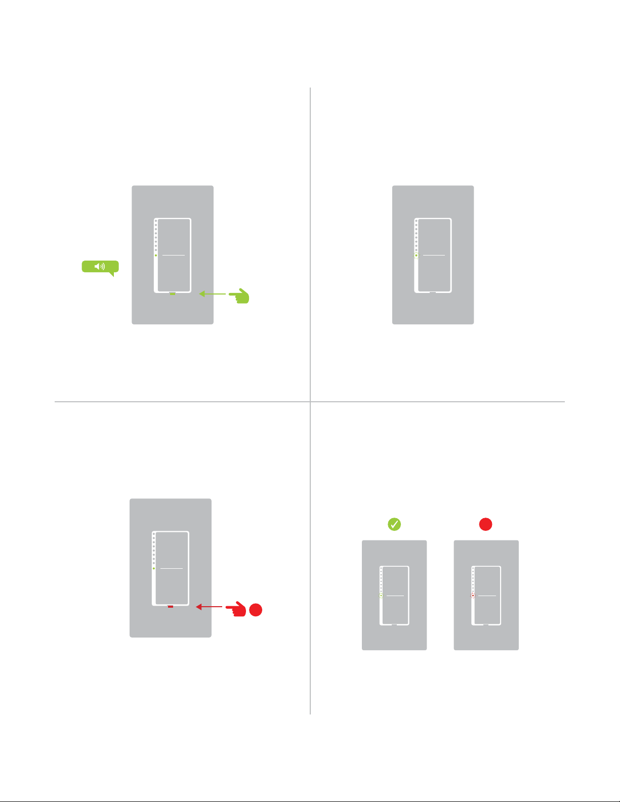
After installing the Wall Switch, the switch produces a long, continuous beep
Your Wall Switch has been wired incorrectly and will not function.
Try this:
• Turn o power and verify the wire connections in the junction box are secure, not showing any bare wire
and labeled correctly. The color of wire in your junction box may dier from the installation diagrams and
it is possible that the function of the wire is incorrect for its color. Use a voltage detector or multi-meter to
properly identify line, load and neutral. If you are unable to do so, contact an electrician.

38
Certications and Warnings
This device complies with FCC Rules and Industry Canada license-exempt RSS standard(s). Operation is
subject to the following two conditions: (1) this device may not cause harmful interference, and (2) this device
must accept any interference, including interference that may cause undesired operation of the device.
Le present appareil est conforme aux CNR d’Industrie Canada applicables aux appareils radio exempts
de licence. L’exploitation est autorise aux deux conditions suivantes: (1) l’appareil ne doit pas produire de
brouillage, et (2) l’utilisateur de l’appareil doit accepter tout brouillage radiolectrique subi, mme si le brouillage est
susceptible d’en compromettre le fonctionnement.
Changes or modications to this unit voids the user’s authority to operate this product and the manufacturer’s
warranty.
The digital circuitry of this device has been tested and found to comply with the limits for a Class B digital
device, pursuant to Part 15B of the FCC Rules. These limits are designed to provide reasonable protection
against harmful interference in residential installations. This equipment generates, uses, and can radiate
radio frequency energy and, if not installed and used in accordance with the instructions, may cause harmful
interference to radio and television reception. However, there is no guarantee that interference will not occur in a
particular installation. If this device does cause such interference, which can be veried by turning the device o
and on, the user is encouraged to eliminate the interference by one or more of the following measures:
- Re-orient or relocate the receiving antenna of the device experiencing the interference
- Increase the distance between this device and the receiver
- Connect the device to an AC outlet on a circuit dierent from the one that supplies power to the receiver
- Consult the dealer or an experienced radio/TV technician
WARNING: Changes or modications to this device not expressly approved by the party responsible for
compliance could void the user’s authority to operate the equipment.

39
Product Warranty
Limited Warranty
Seller warrants to the original consumer purchaser of this product that, for a period of two years from the date
of purchase, this product will be free from defects in material and workmanship and will perform in substantial
conformity to the description of the product in this Owner’s Manual. This warranty shall not apply to defects or
errors caused by misuse or neglect. If the product is found to be defective in material or workmanship, or if the
product does not perform as warranted above during the warranty period, Seller will either repair it, replace it,
or refund the purchase price, at its option, upon receipt of the product at the address below, postage prepaid,
with proof of the date of purchase and an explanation of the defect or error. The repair, replacement, or refund
that is provided for above shall be the full extent of Seller’s liability with respect to this product. For repair or
replacement during the warranty period, call 866-243-8022 with the Model # and Revision # of the device to
receive an RMA# and send the product, along with all other required materials to:
Insteon
ATTN: Receiving
16542 Millikan Ave.
Irvine, CA 92606-5027
Limitations
The above warranty is in lieu of and Seller disclaims all other warranties, whether oral or written, express or
implied, including any warranty or merchantability or tness for a particular purpose. Any implied warranty,
including any warranty of merchantability or tness for a particular purpose, which may not be disclaimed
or supplanted as provided above shall be limited to the two-year of the express warranty above. No other
representation or claim of any nature by any person shall be binding upon Seller or modify the terms of the
above warranty and disclaimer.
Home automation devices have the risk of failure to operate, incorrect operation, or electrical or mechanical
tampering. For optimal use, manually verify the device state. Any home automation device should be viewed as
a convenience, but not as a sole method for controlling your home.
In no event shall Seller be liable for special, incidental, consequential, or other damages resulting from
possession or use of this device, including without limitation damage to property and, to the extent permitted by
law, personal injury, even if Seller knew or should have known of the possibility of such damages. Some states
do not allow limitations on how long an implied warranty lasts and/or the exclusion or limitation of damages, in
which case the above limitations and/or exclusions may not apply to you. You may also have other legal rights
that may vary from state to state.
Protected under U.S. and foreign patents (see www.insteon.com/patents)
©2015 Insteon
Rev 02.10.15