
Technical Support and E-Warranty Certificate www.vevor.com/support
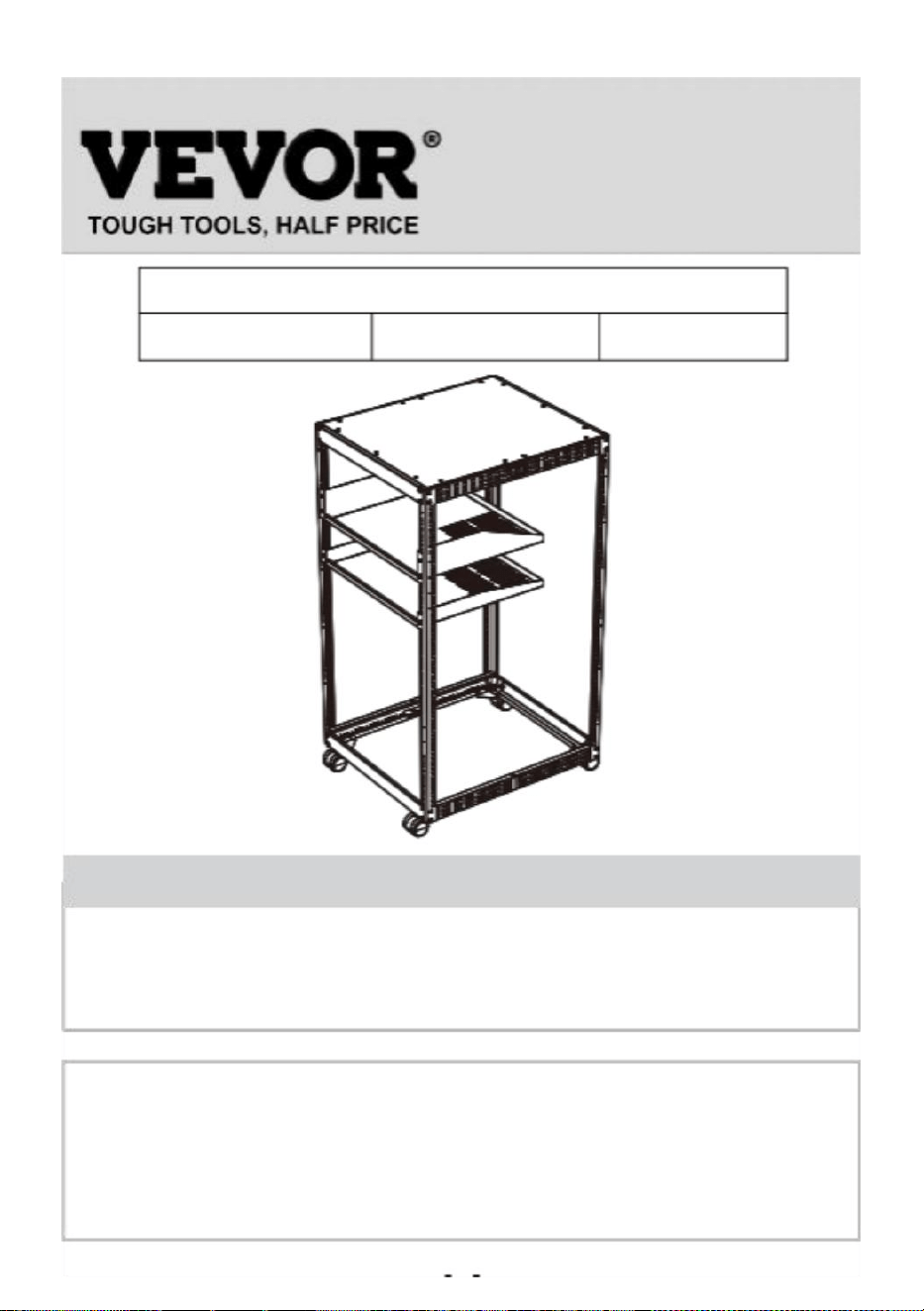
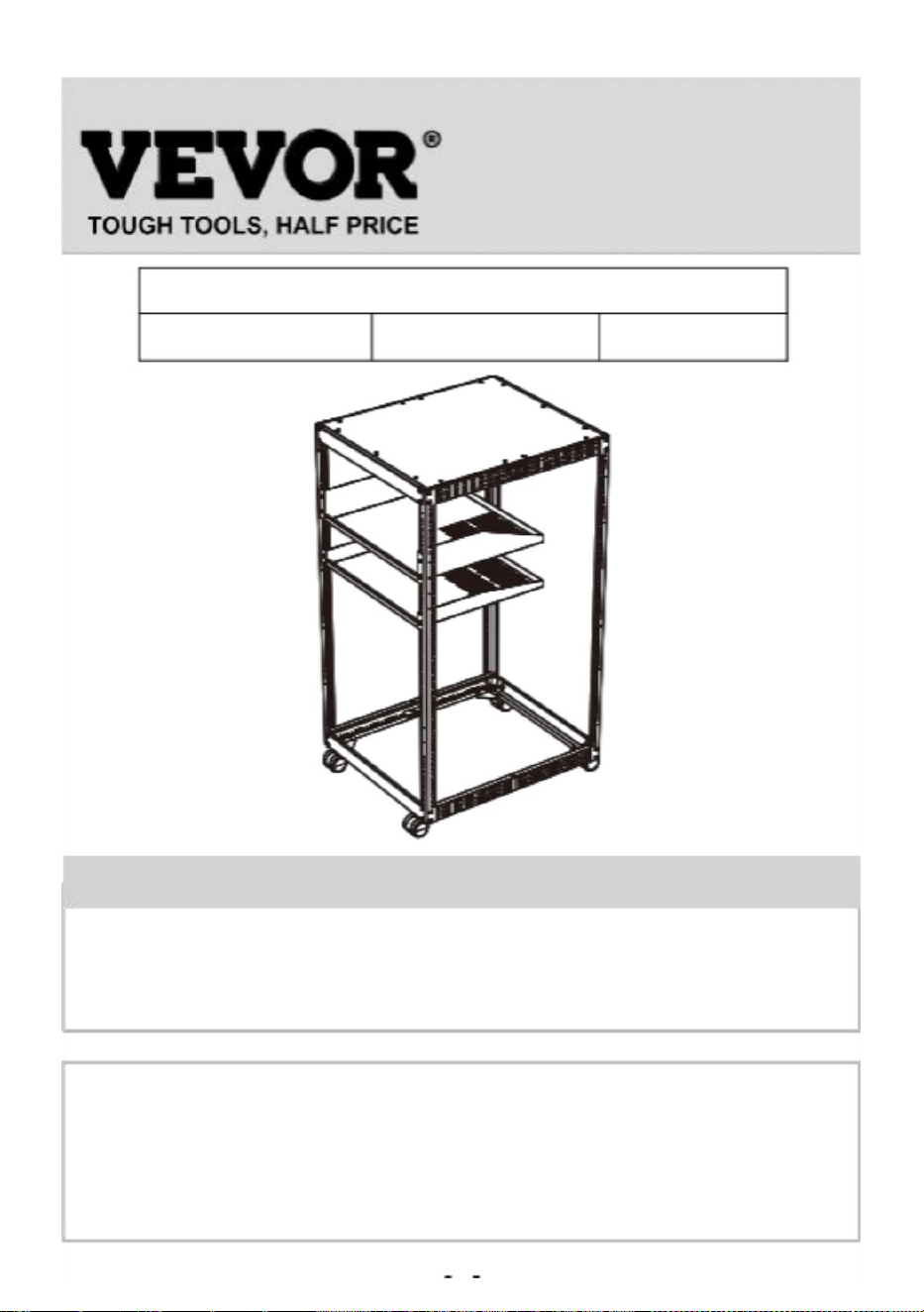
ADJUSTABLE OPEN FRAME
SERVER RACK
USER MANUAL
We continue to be committed to provide you tools with competitive price.
"Save Half", "Half Price" or any other similar expressions used by us only represents an estimate
of savings you might benefit from buying certain tools with us compared to the major top brands
and does not necessarily mean to cover all categories of tools offered by us. You are kindly
reminded to verify carefully when you are placing an order with us if you are actually saving half
in comparison with the top major brands.
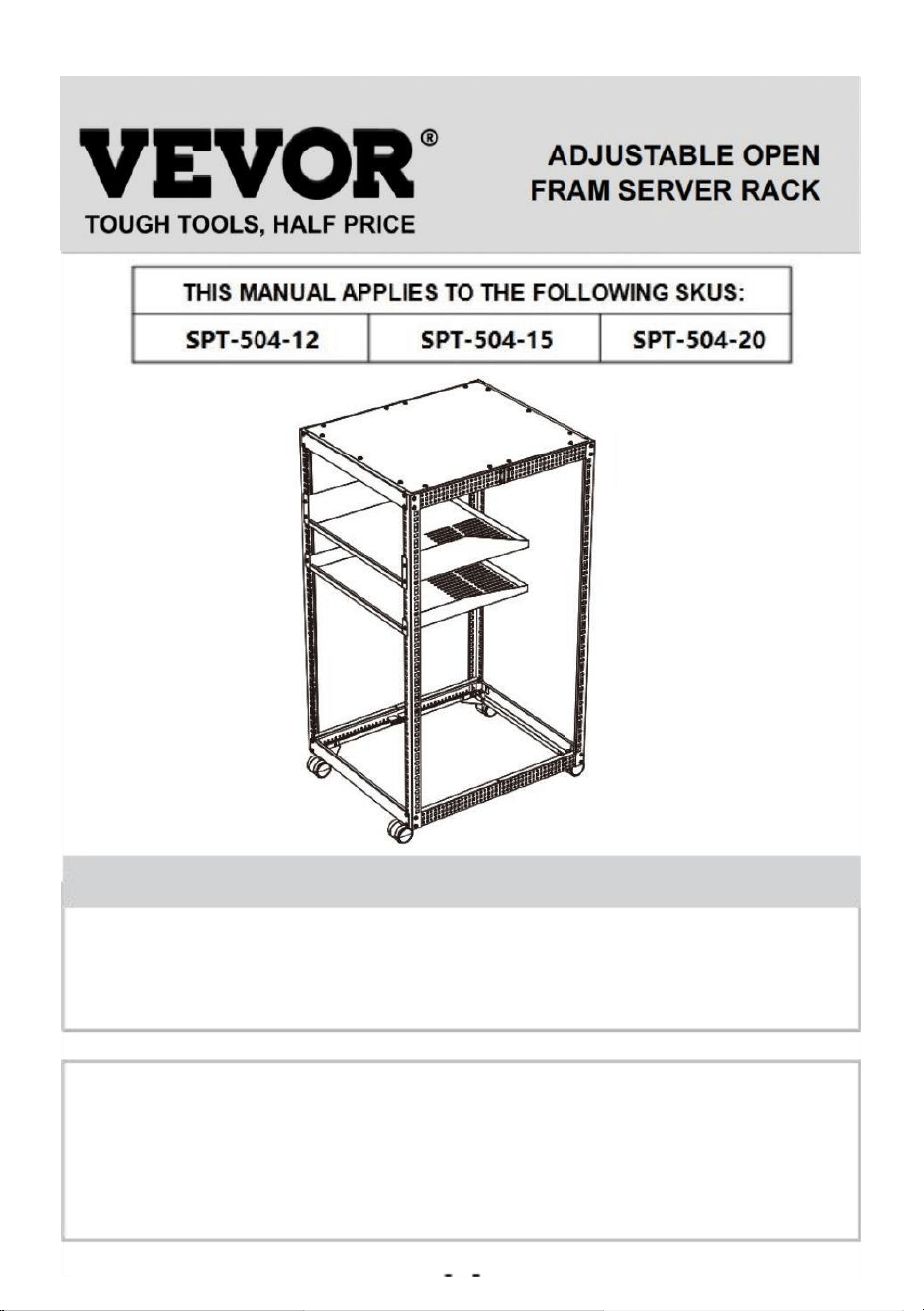
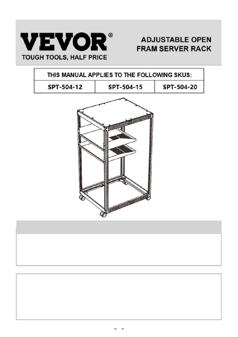
ADJUSTABLE OPEN
FRAM SERVER RACK
THIS MANUAL APPLIES TO THE FOLLOWING SKUS:
HT-W6412 HT-W6415 HT-W6420
NEED HELP? CONTACT US!
Have product questions? Need technical support? Please feel free to
contact us:
Technical Support and EWarranty Certificate
www.vevor.com/support
This is the original instruction, please read all manual instructions
carefully before operating. VEVOR reserves a clear interpretation of
our user manual. The appearance of the product shall be subject to the
product you received. Please forgive us that we won't inform you again
if there are any technology or software updates on our product.
- 1 -

- 2 -
Thank you for purchasing the Performance Series Wall Mount Cabinet
from VEVOR.
Every effort has been made to ensure the accuracy of the information in
this product manual.
COMPLIANCE STATEMENTS
Use of Trademarks,Registered Trademarks, and other Protected
Names and Symbols
This manual may make reference to trademarks, registered trade-
marks,and other protected names and/or symbols of third-party com-
panies not related in any way to vevor. Where they occur these refer-
ences are for illustrative purposes only and do not represent an
endorsement of a product or service by vevor, or an endorsement of
the product(s)to which this manual applies by the third-party company
in question. Regardless of any direct acknowledgment elsewhere in
the body of this document, vevor hereby acknowledges that all trade-
marks, registered trademarks,service marks, and other protected
names and/or symbols contained in this manual and related docu-
ments are the property of their respective holders.
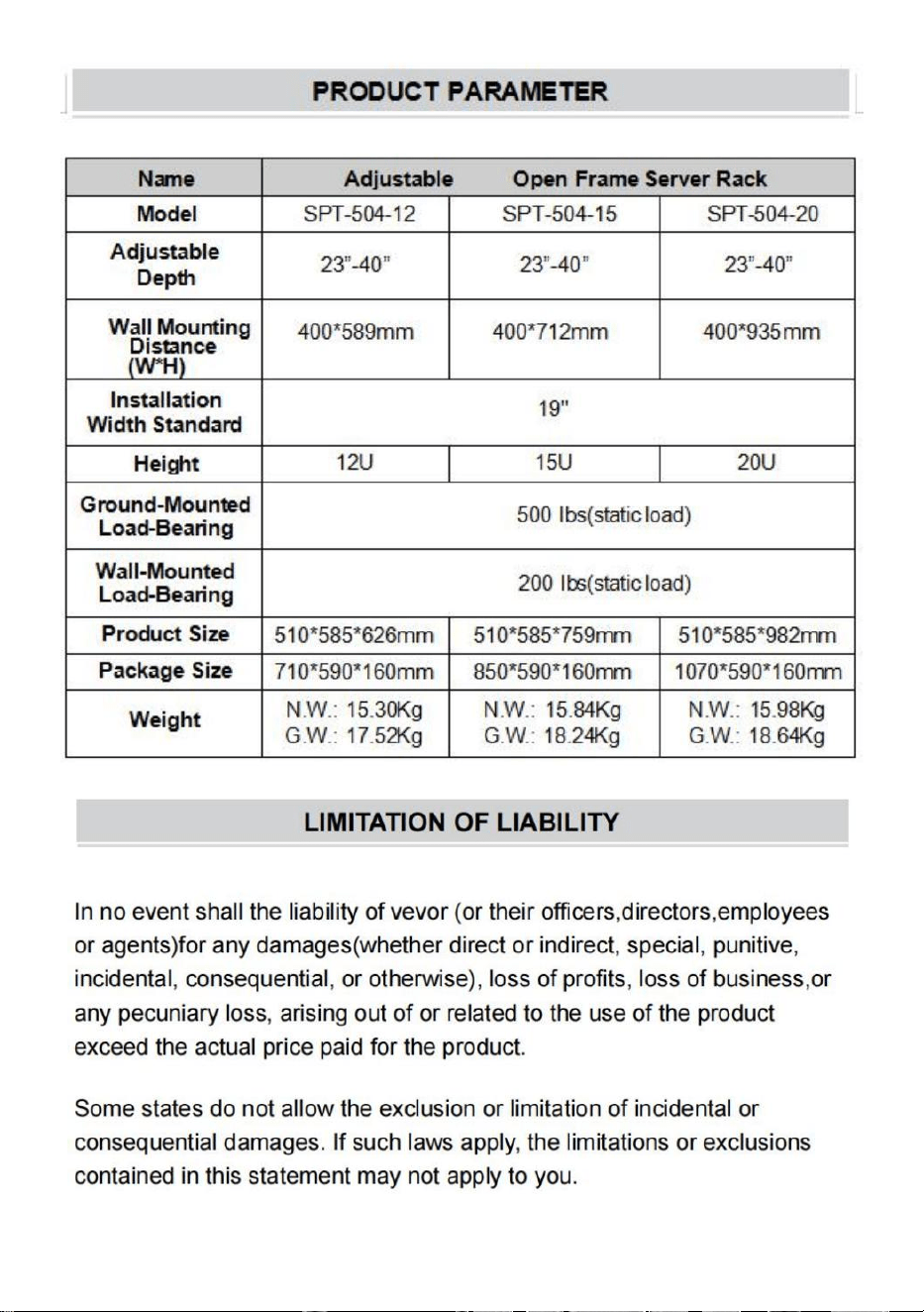
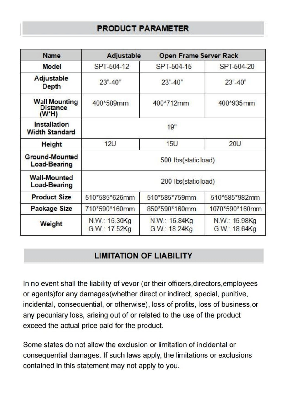
WARNING STATEMENTS
Make sure that you assemble this product according to the instructions.
Do not exceed the weight capacity of this product. Overloading this
product might result in injury or property damage. This product can
support the following weight: Ground-mounted load-bearing: 500Ib,
Wall-mounted load-bearing: 200Ib.
This product is intended for indoor use only and should not be used
outdoors.
This enclosure is extremely heavy. Never attempt to move or lift this

- 3 -
:
enclosure without assistance.
Tipping hazard! Extending multiple components from this enclosure
increases the chance that the enclosure will tip over. To avoid this risk, do
not extend more than one component from the enclosure.
Do not place any items on this enclosure and do not stack the enclosure
on top of another enclosure.
Keep liquid away from this enclosure.
Make sure that you install the enclosure in an area that can handle the
combined weight of the enclosure and the equipment that you intend to
place inside of the enclosure.
This product requires an earth-ground connection. Do not use this
product without an earth-ground connection.
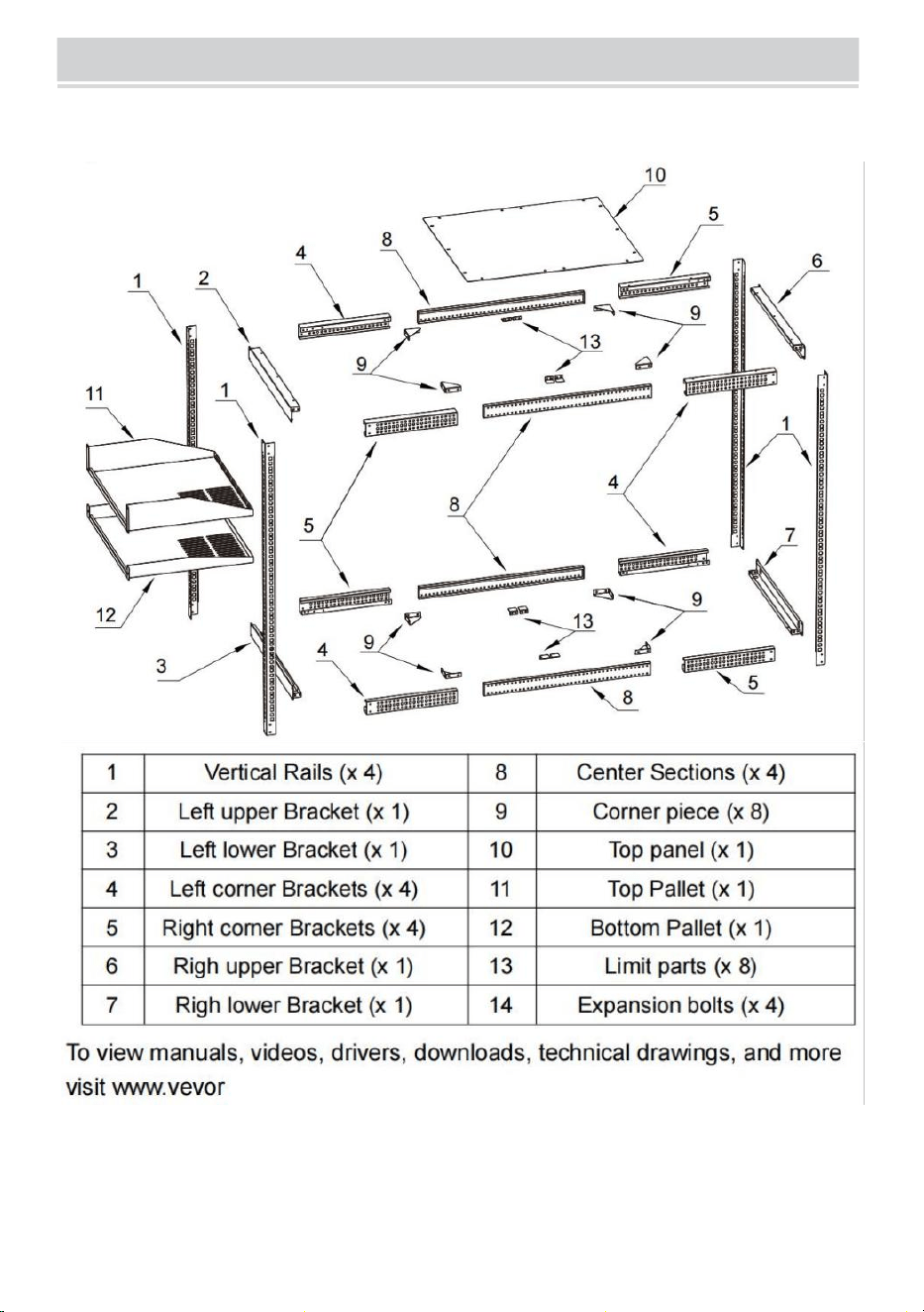
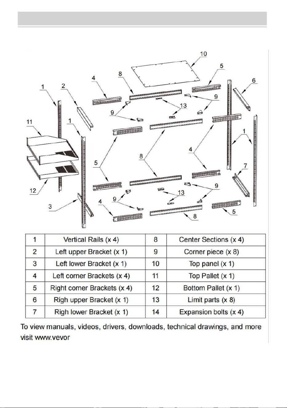
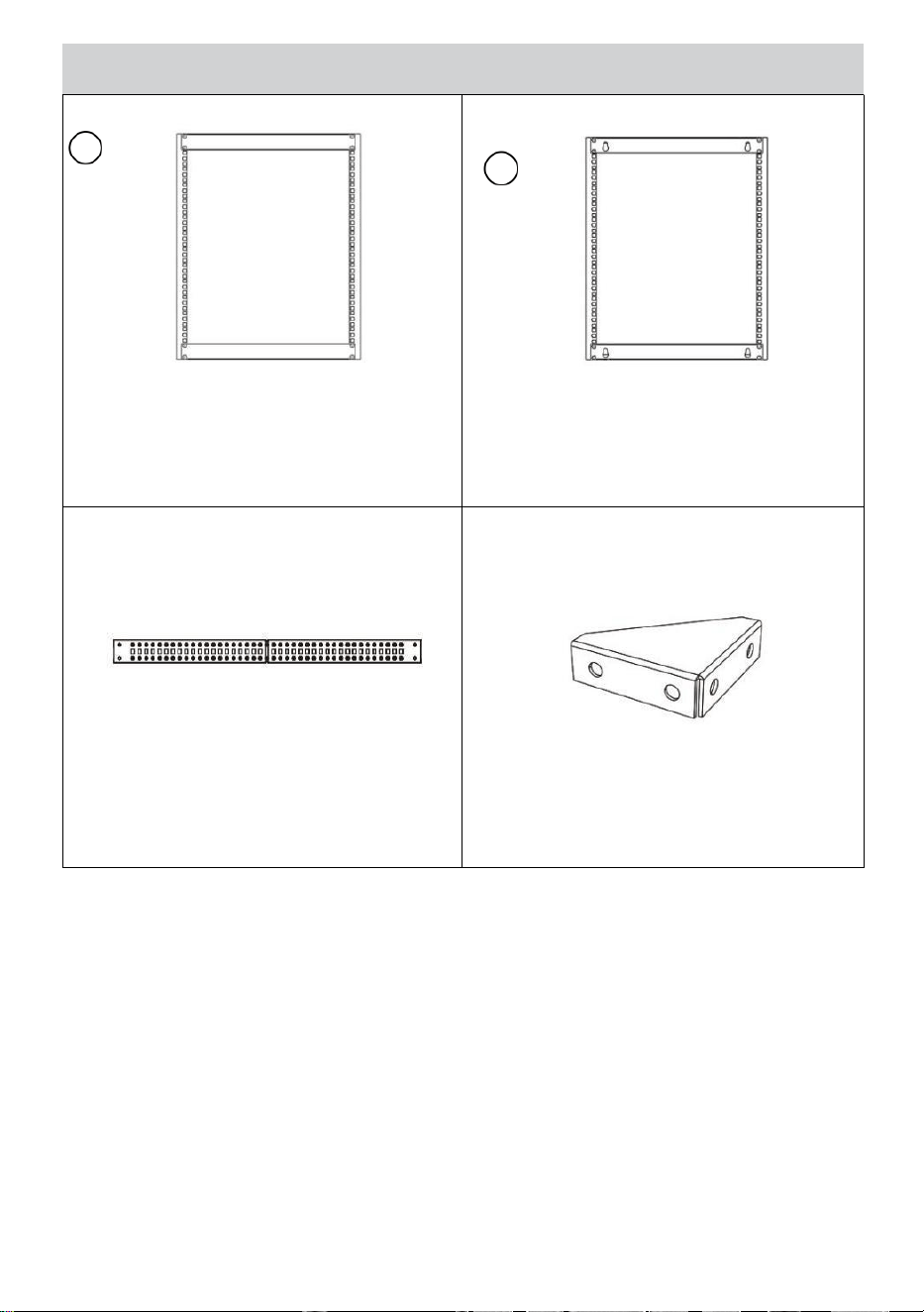
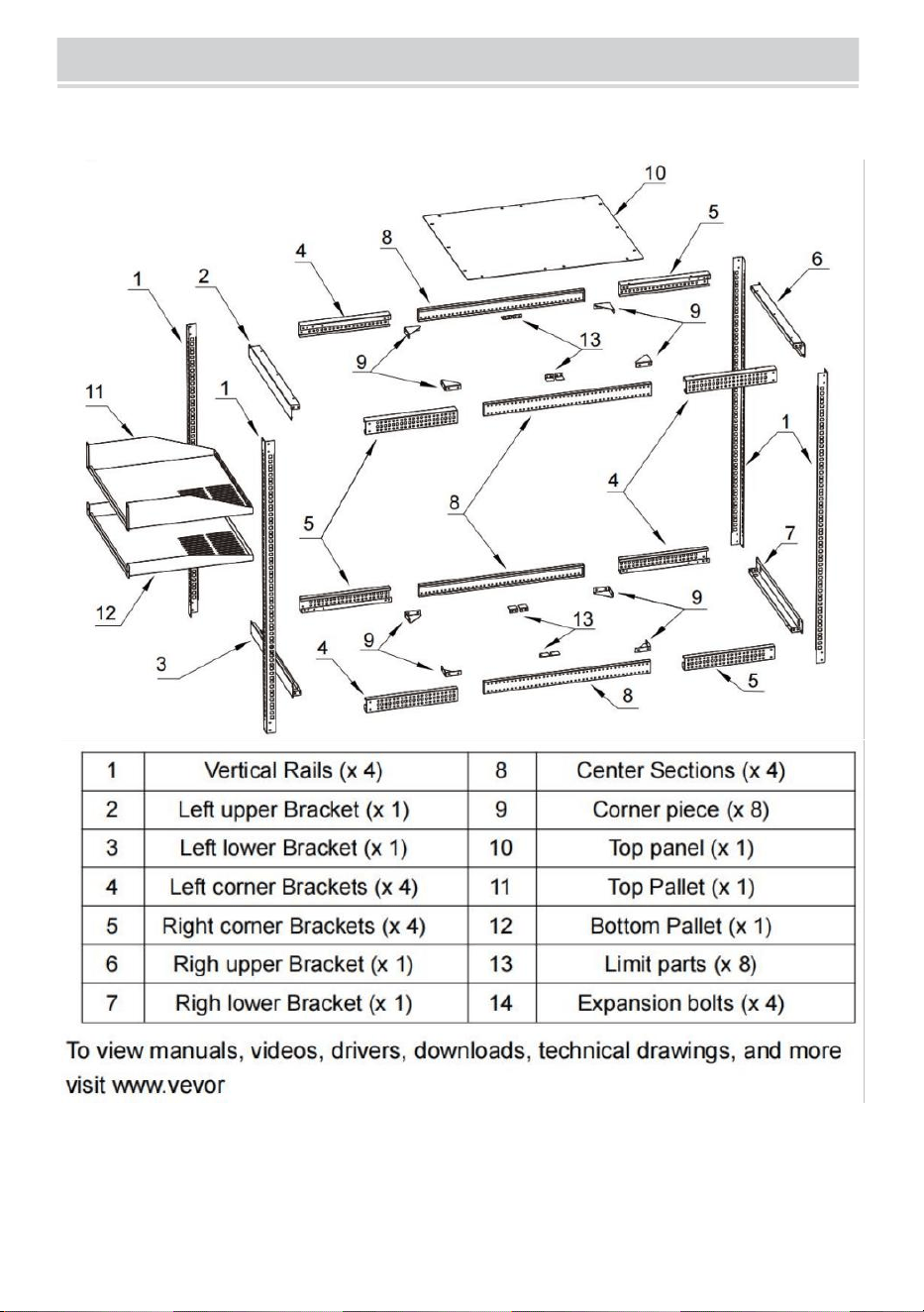
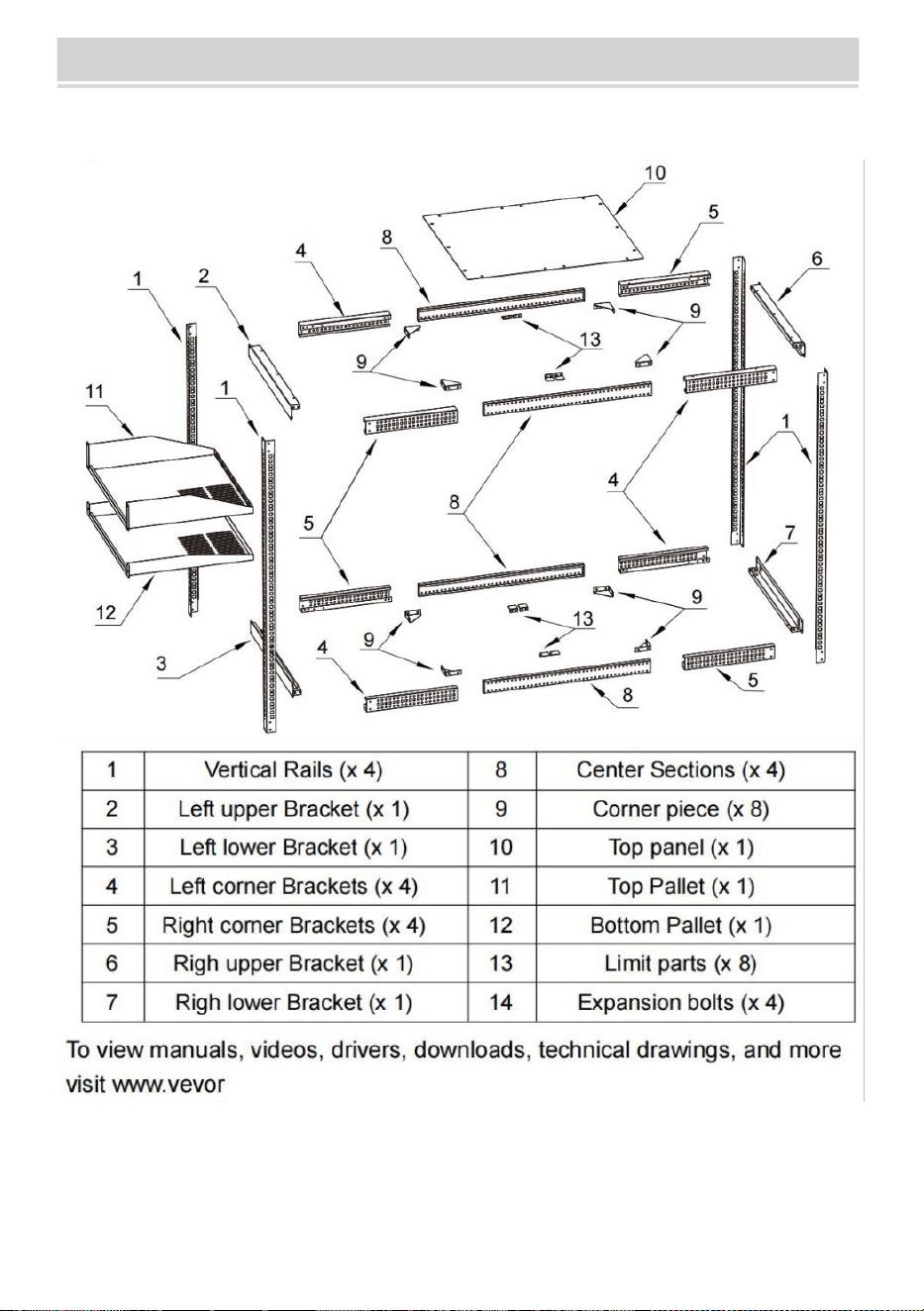
PRODUCT DIAGRAM
- 4 -
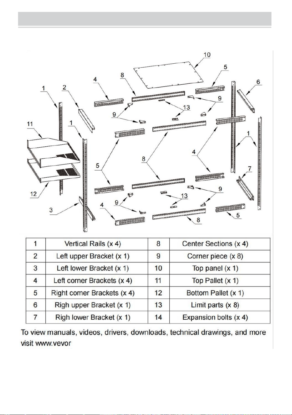
Expanded View
- 5 -
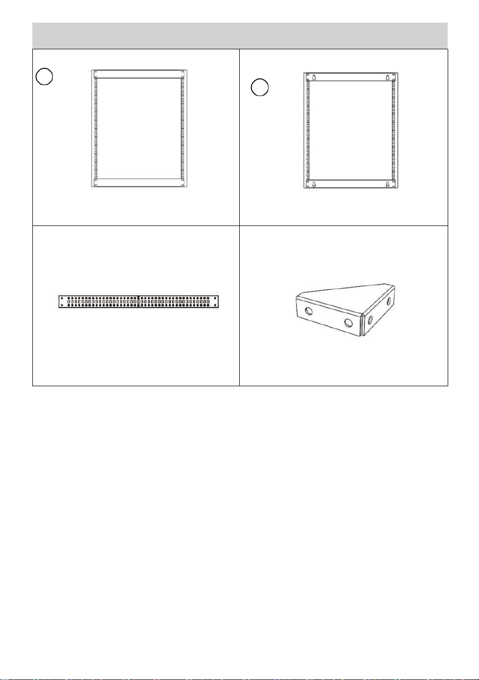
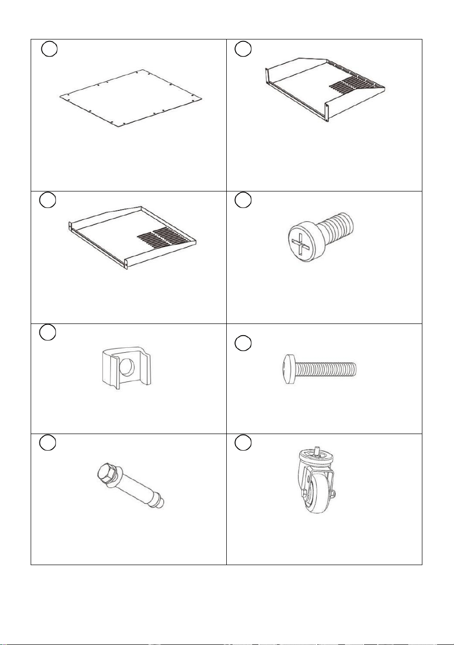
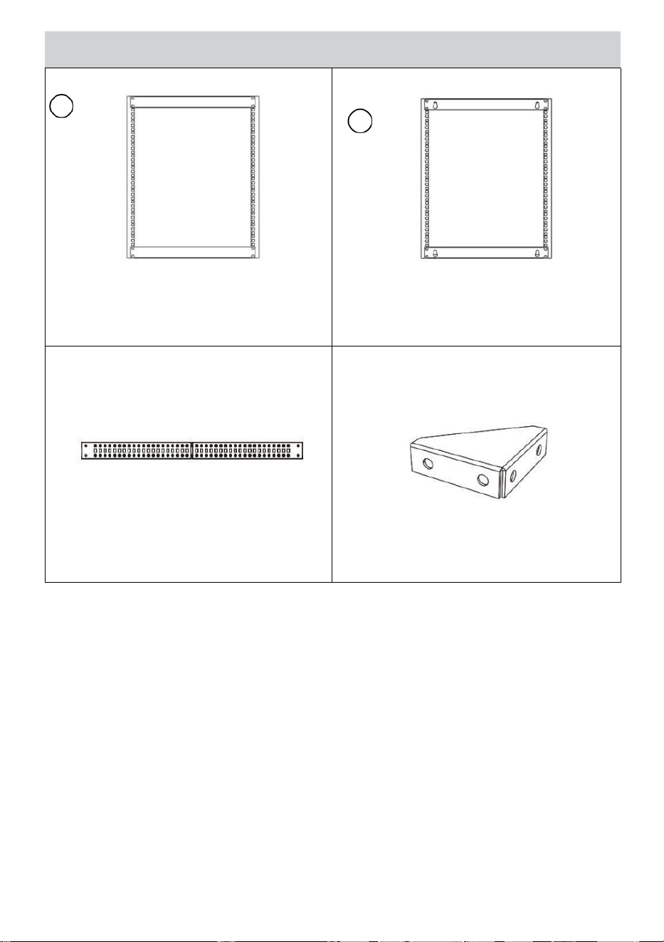
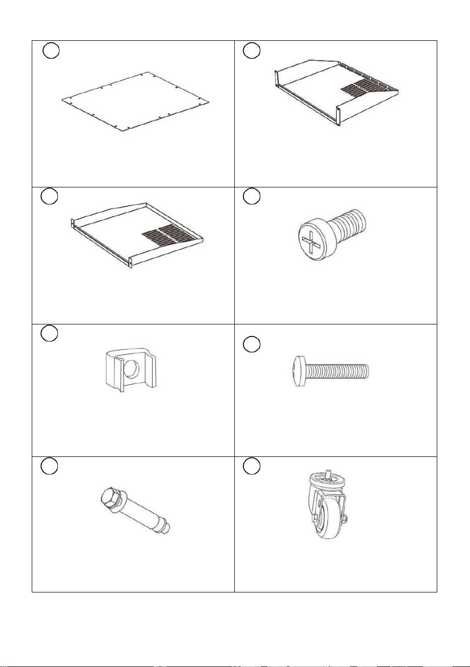
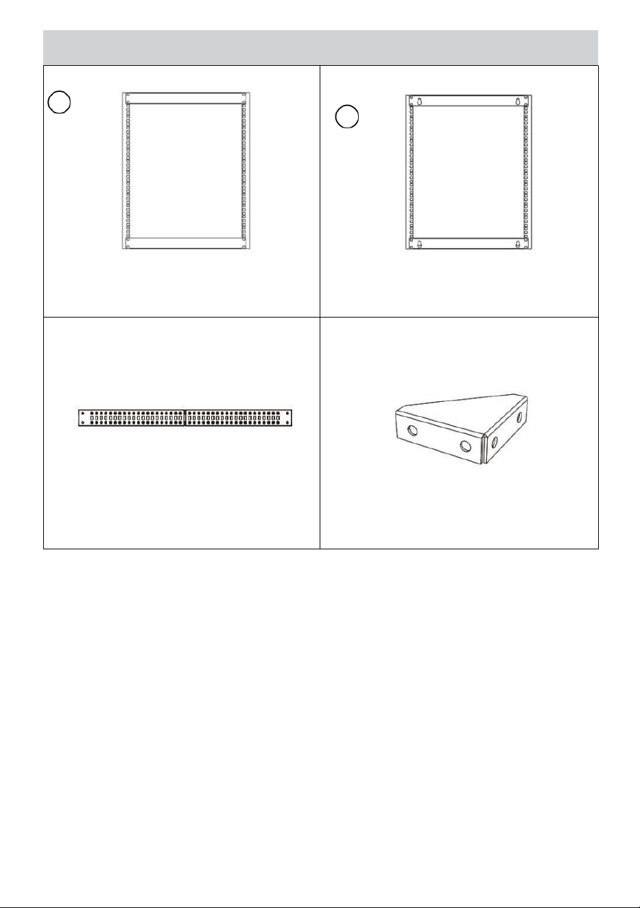
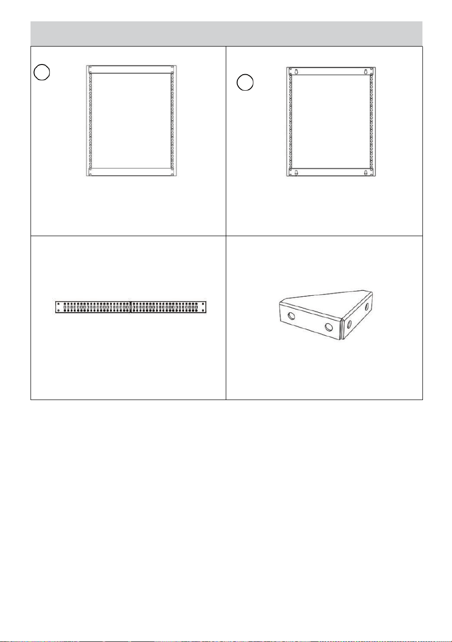
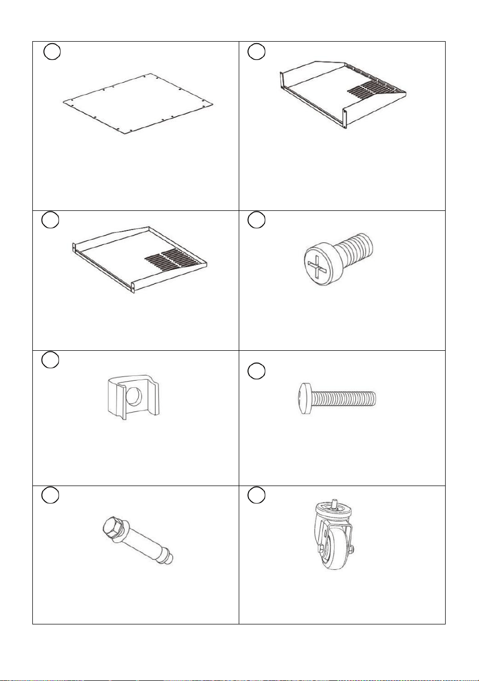
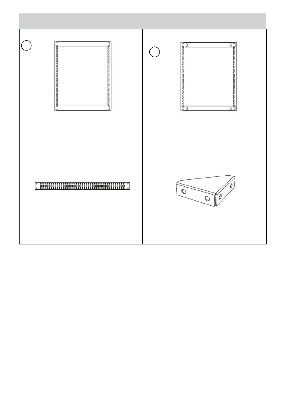
PACKAGE CONTENTS
1
Front Frame
Qty: 1
2
Rear Frame
Qty: 1
③
Side Sections
Qty: 4
④
Corner Piece
Qty: 8
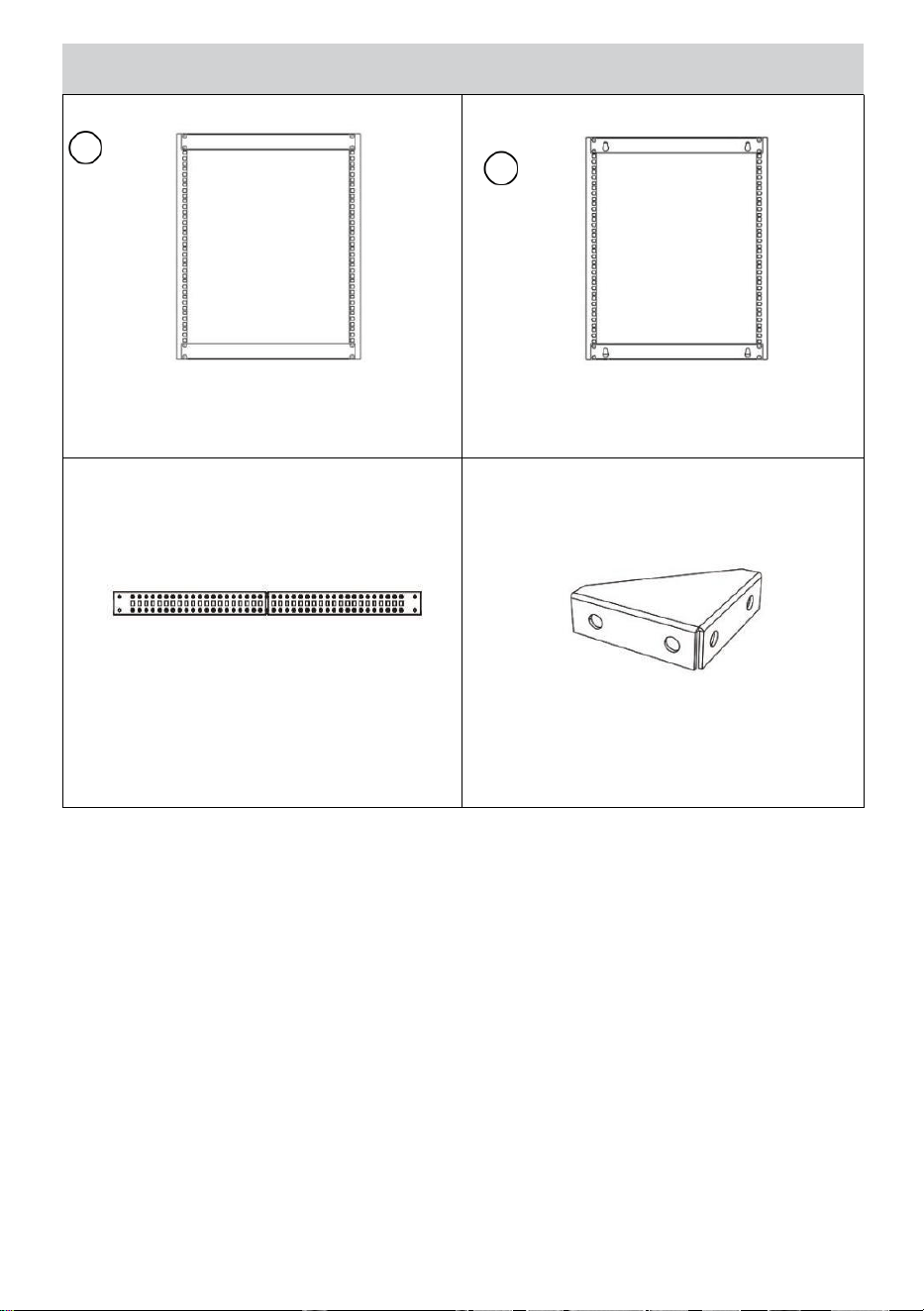
- 6 -
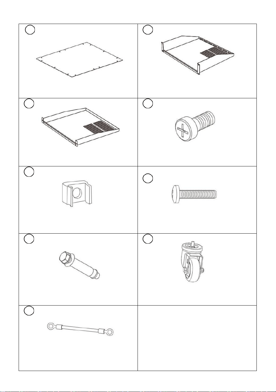
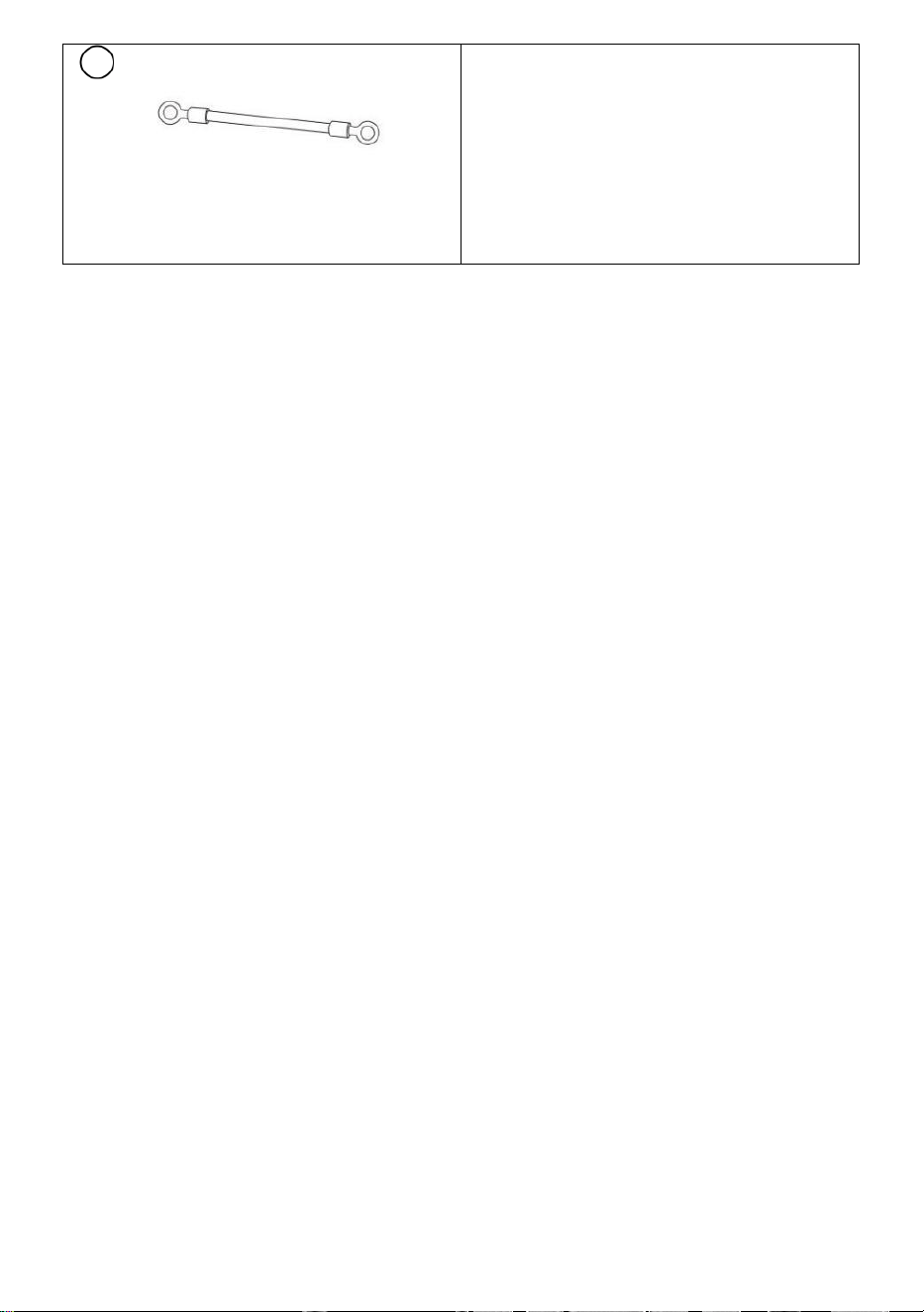
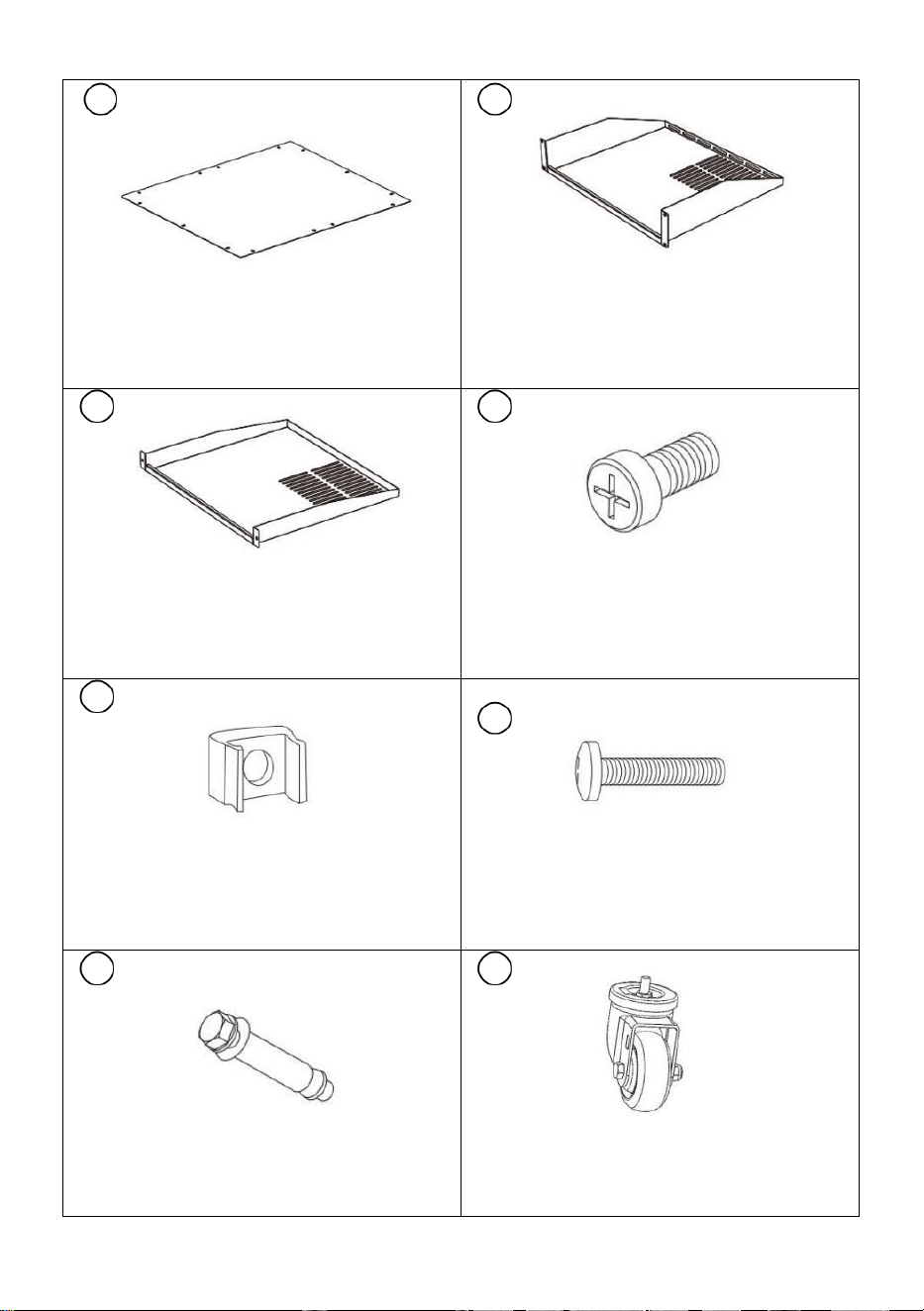
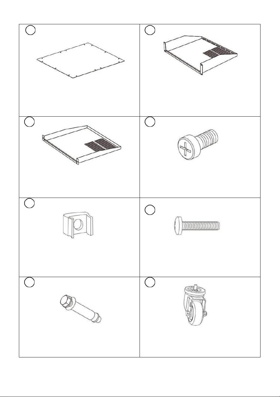
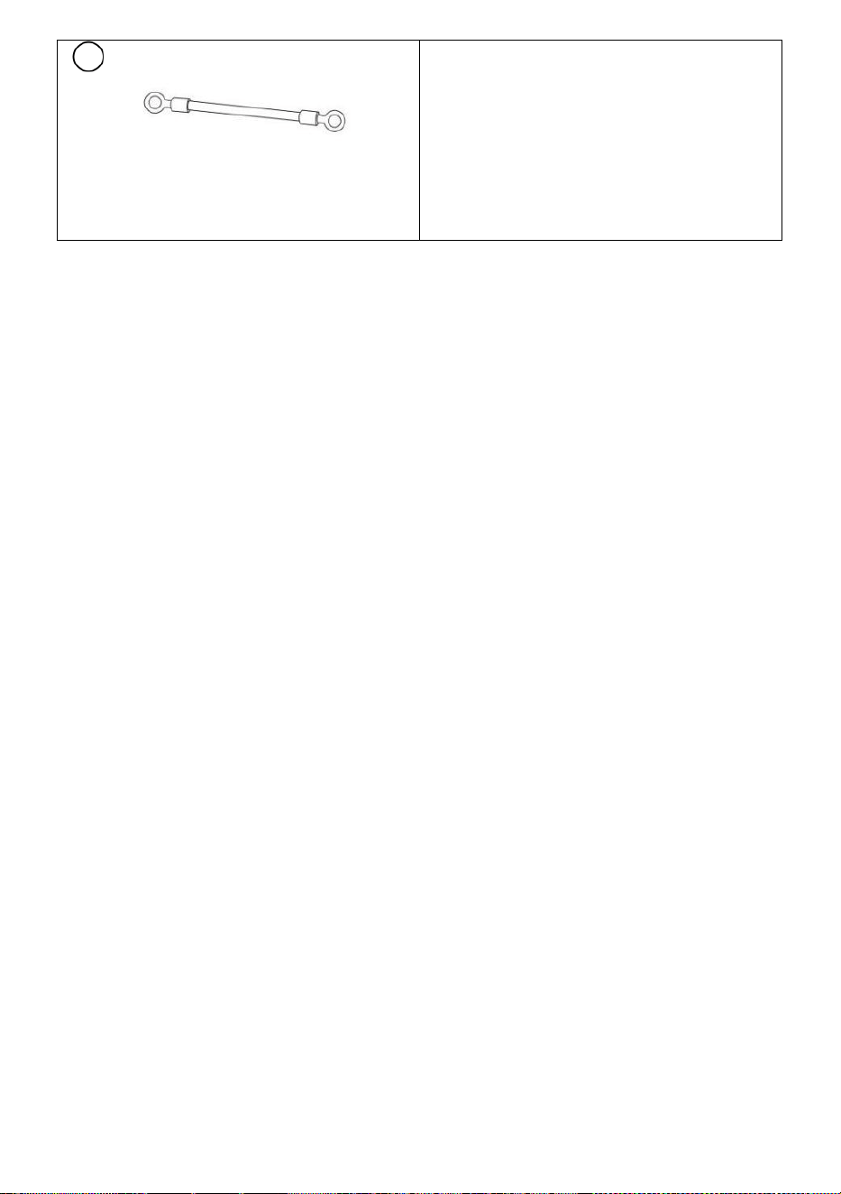
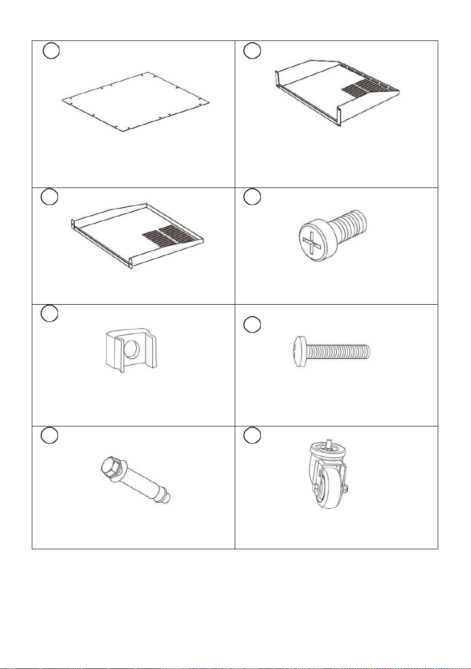
5
6
Top Pallet
Qty: 1
Top Panel
Qty: 1
7
Bottom Pallet
Qty: 1
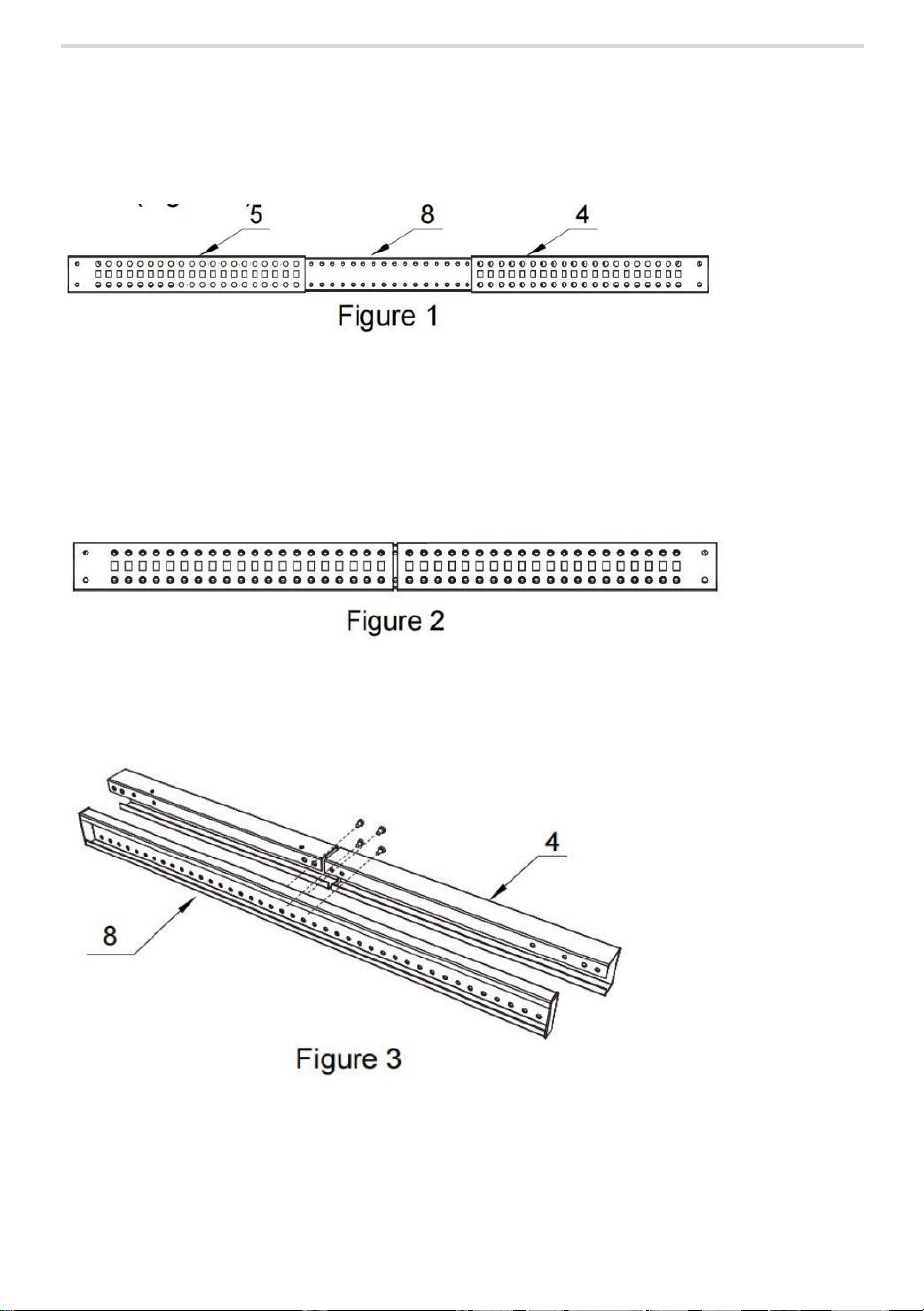
8
M5*10 Cross Head Screws
Qty: 80
9
10
M6 Cage Nuts
Qty: 16
M6*12 Hex Head Screws
Qty: 16
11
12
Casters
Qty: 4
M10*70mm Expansion Screws
Qty: 4
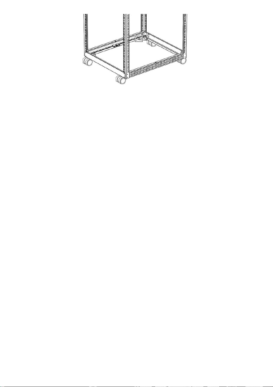
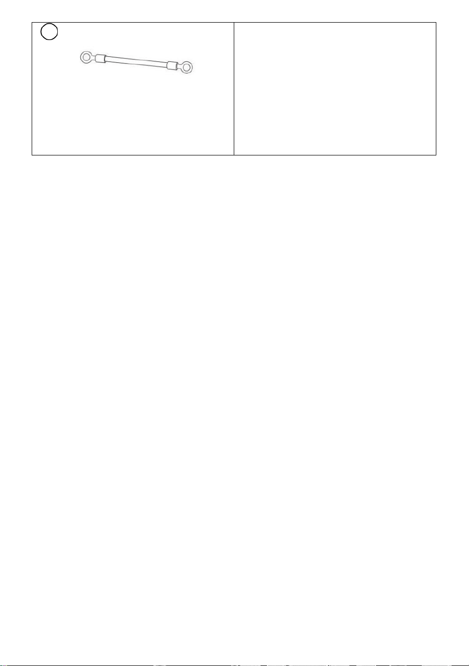
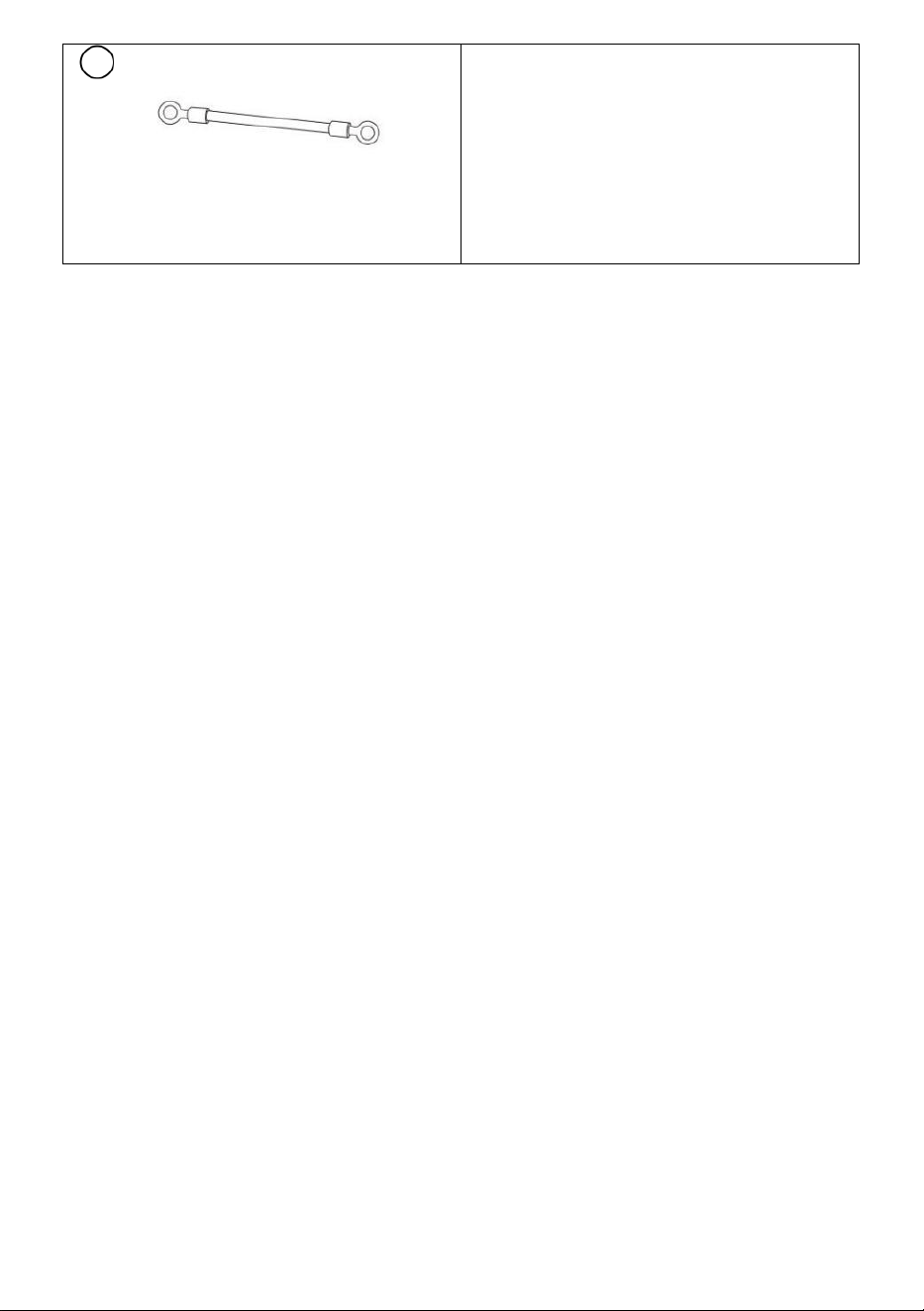
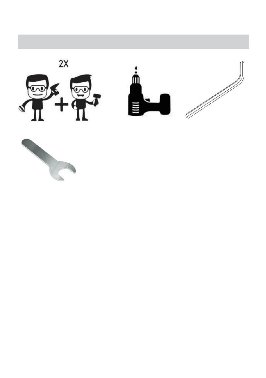
13
Grounding Wire
Qty: 1
- 7 -
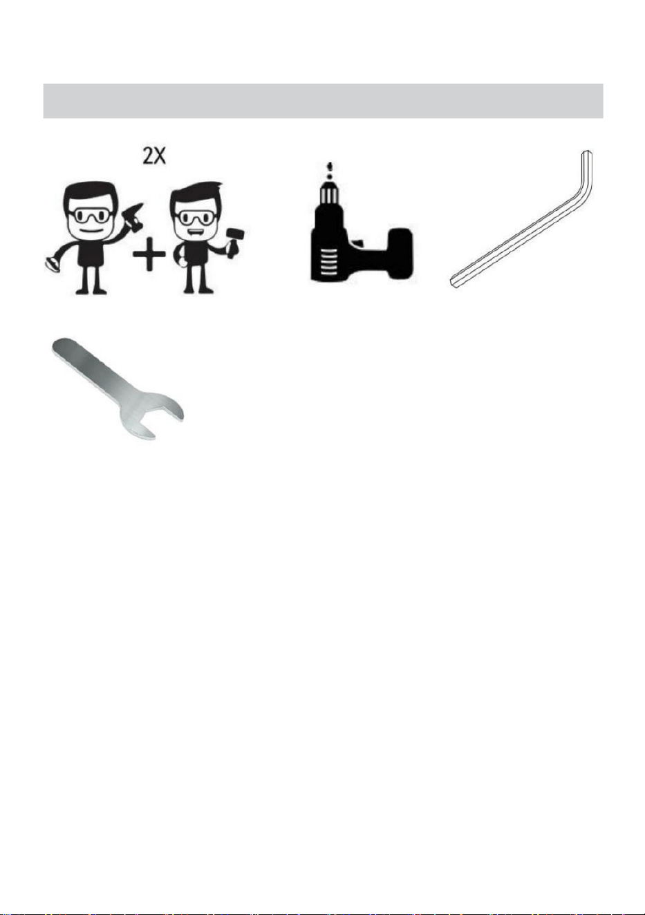
REQUIREMENTS
• Electric screwdriver (sold separately)
• Two People (for assembly)
• Allen key (parts package has included)
• 14mm Spanner (parts package has included)
Note: Two people are required for the Rack assembly.
- 8 -
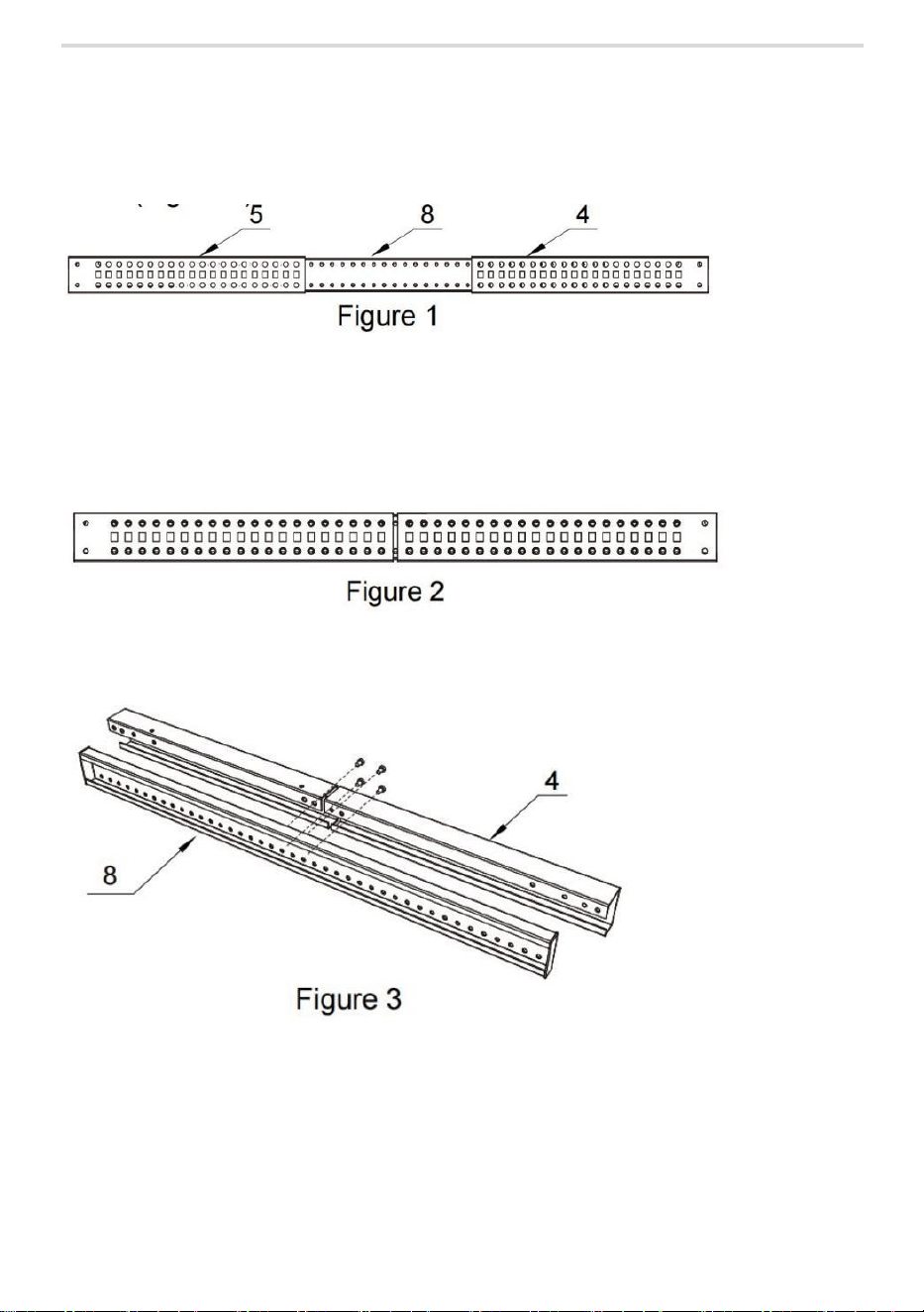
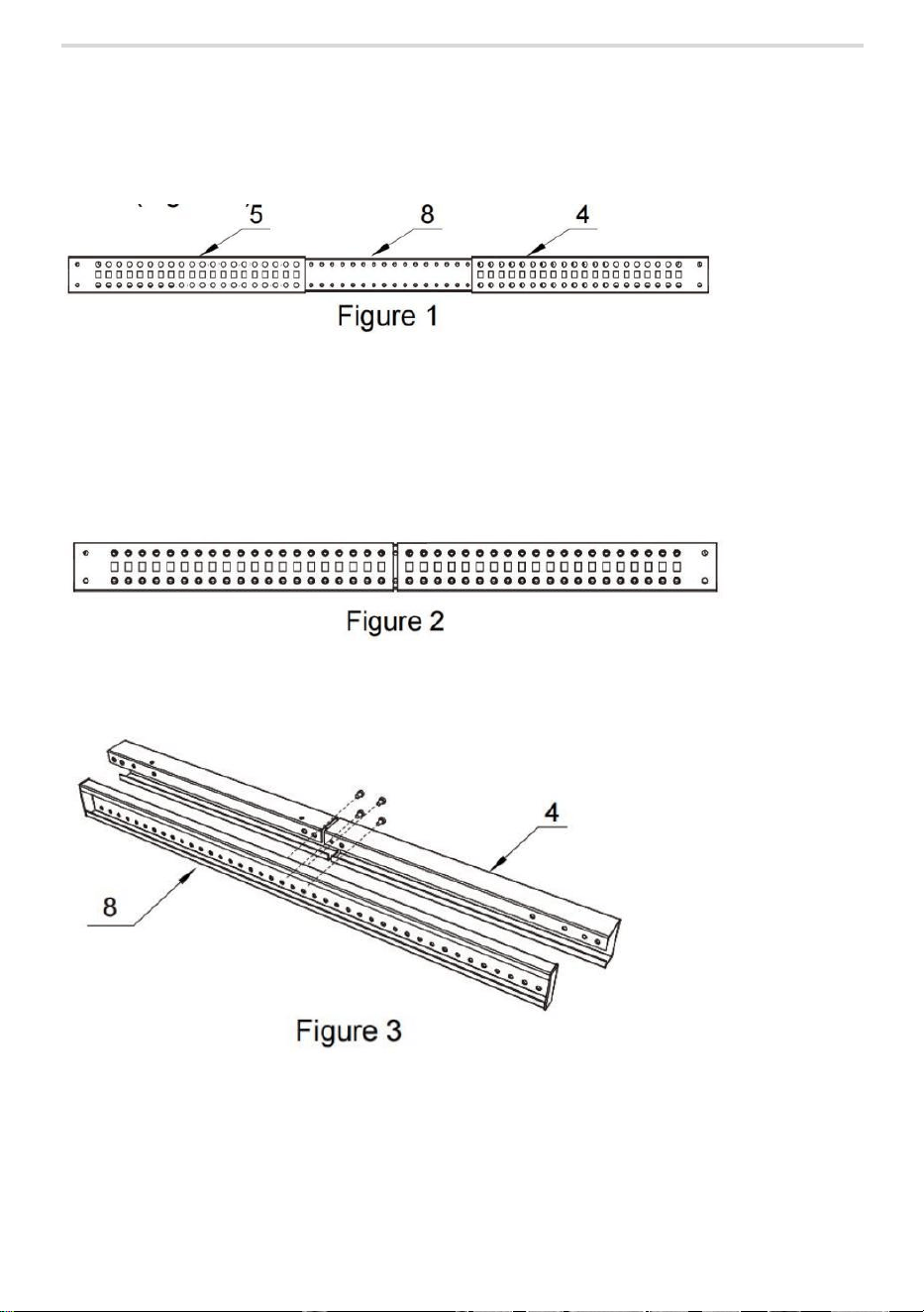
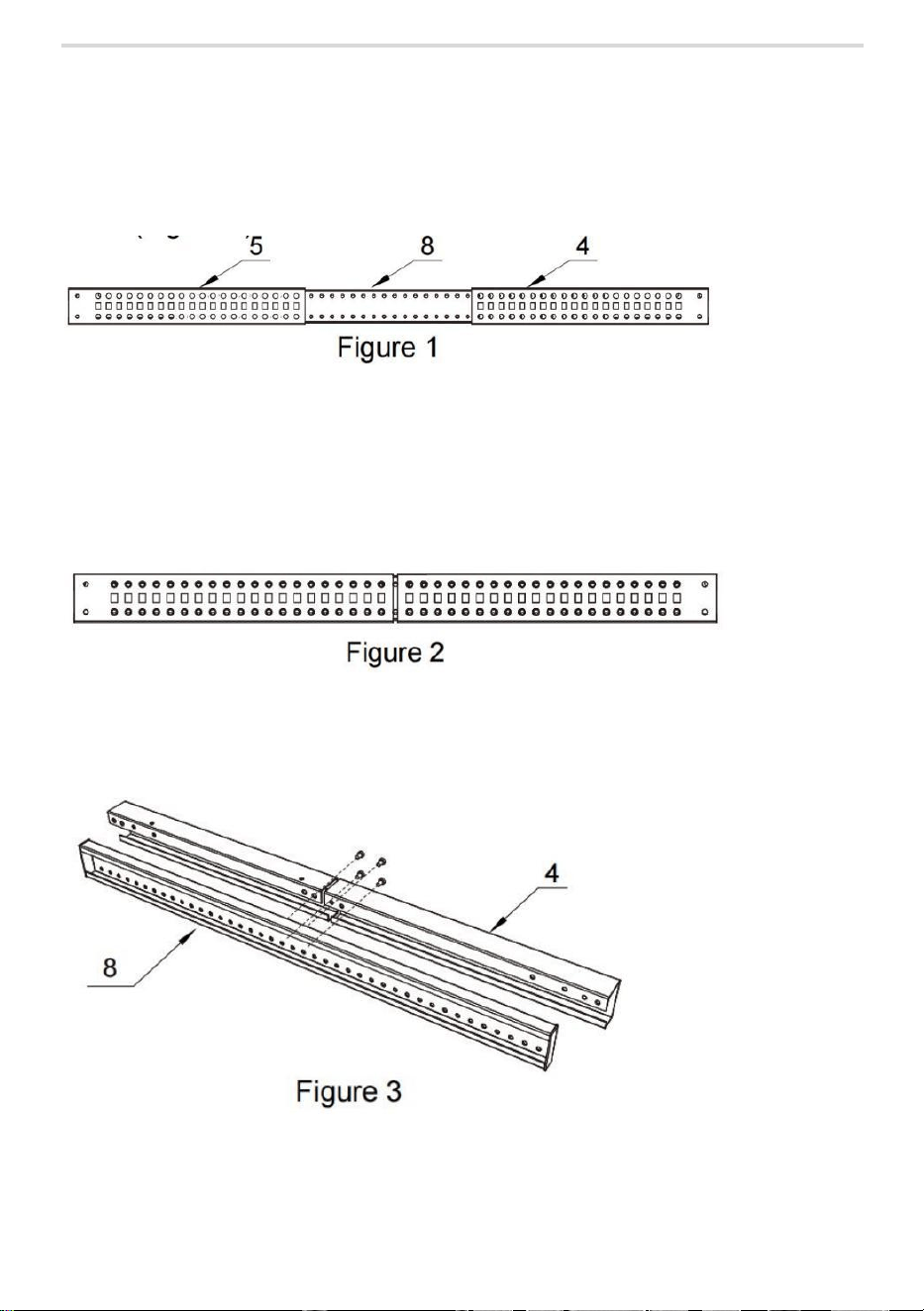
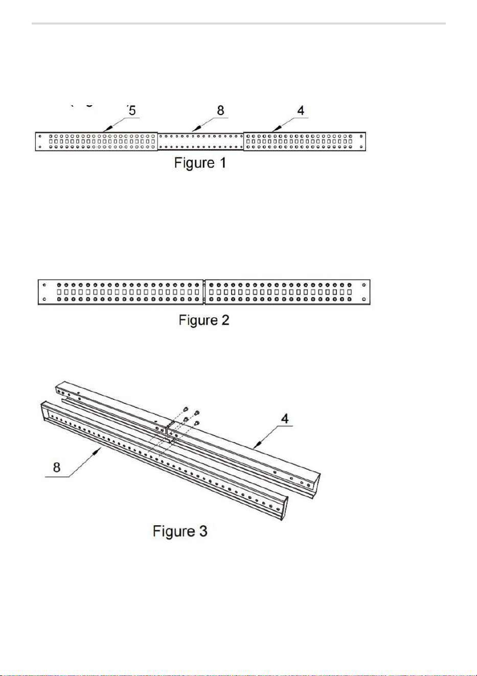
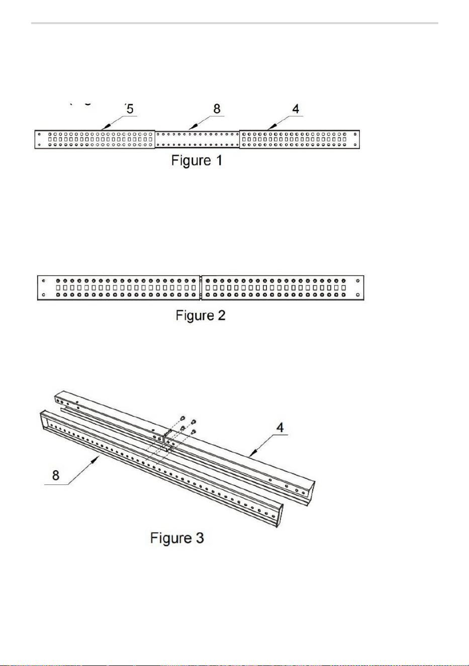
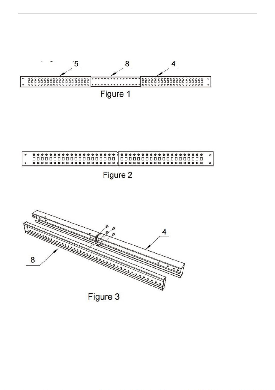
Set the Mounting Depth
1. Align the Left corner Brackets(#4 )and the Right corner Brackets(#4)
with the Center Sections(#8),slide the Corner Brackets overtop of the
Center Sections.(Figure 1)
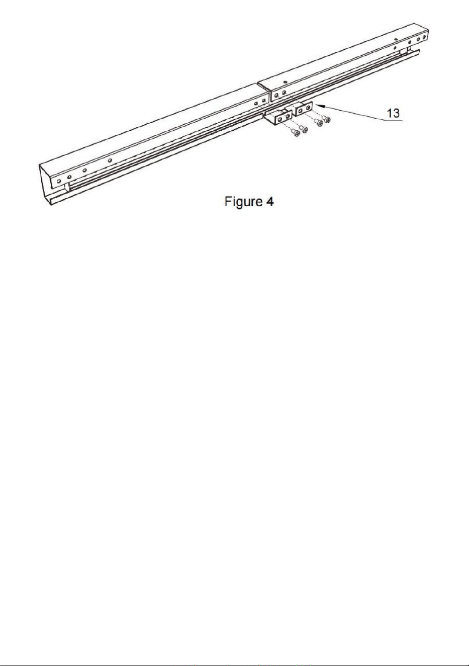
2. Determine the maximum required mounting depth for the Rack
Mountable Equipment.
3. Slide the Left corner Brackets and the Right corner Brackets,inward
along the Center Sections,and align the Center Sections with the hole
on the Left corner Brackets and the Right corner Brackets.(Figure 2)
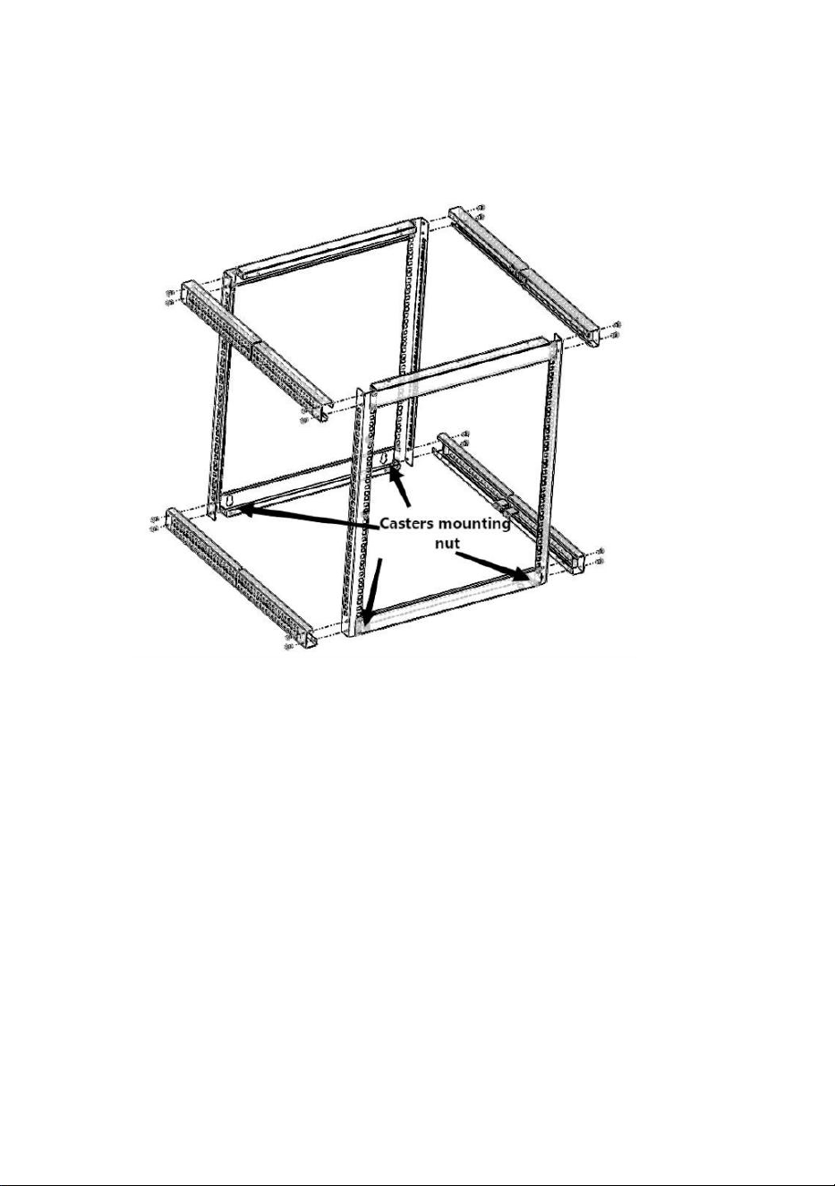
4. Secure with 4pcs M5*10 Cross head screws(⑧) through into the
holes in the Corner Brackets and Center Sections. (Figure 3)
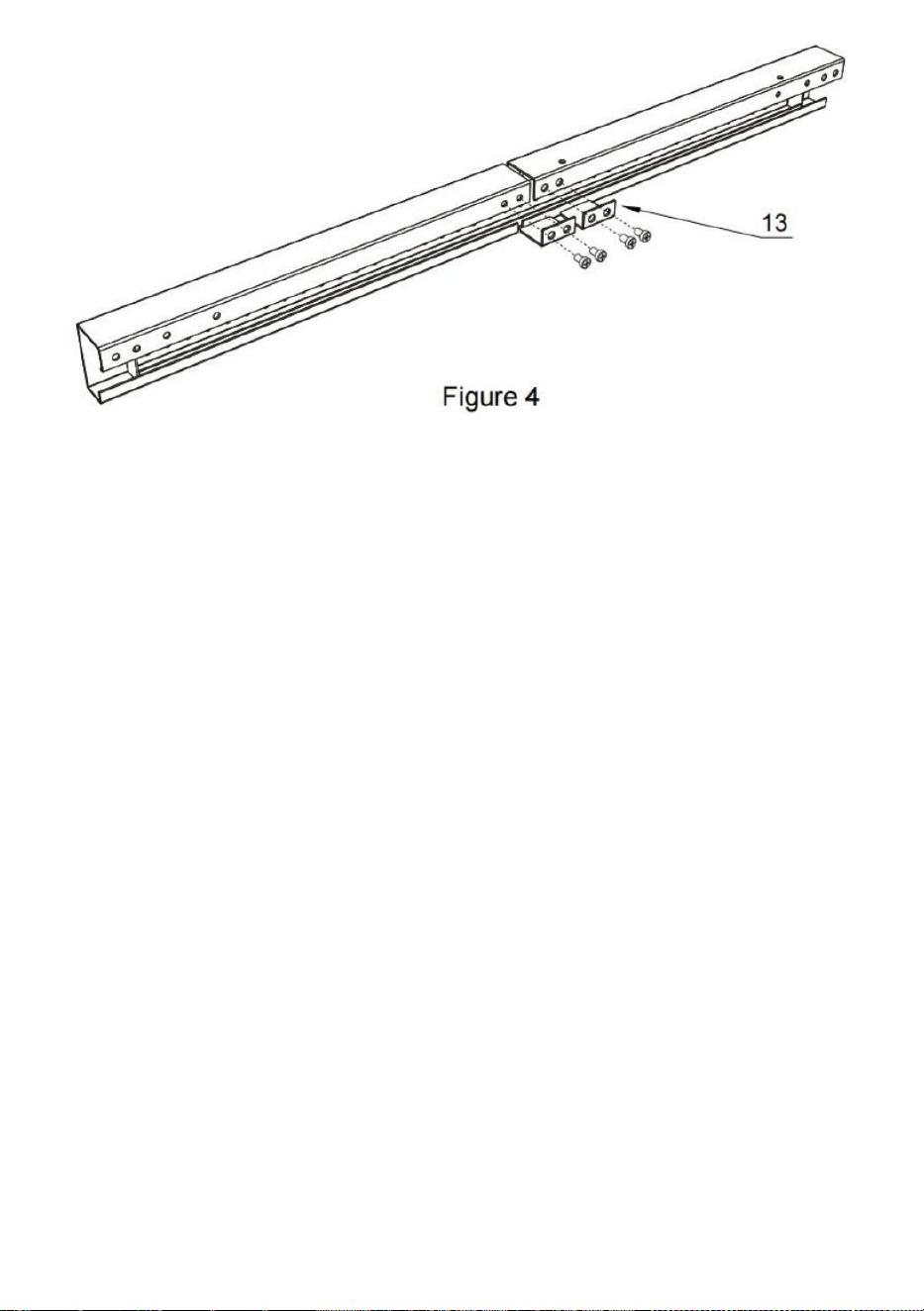
4. Place two Limit parts(#13) on Corner Brackets,Tighten the M5*10
Cross head screws(⑧) using Electric screwdriver. (Figure 4)
5. Repeat the above steps and assemble other 4 center section.

- 9 -
Note:as the above packing contents showed Side
Sections(③),we already assembled Left corner Brackets(#4 ),the
Right corner Brackets(#5),the Center Sections(#8) and Limit
parts(#13)well base one the minimum depth 23”(the rack
adjustable depth is 23”~40”) ,you can keep it if there no need
modify the depth.
You also can modify the depth by return to No.4 process,loosen
the 4pcs M5*10 Cross head screws(⑧) and adjust the depth you
need,and re-secure with the 4pcs M5*10 Cross head screws(
⑧
).

- 10 -
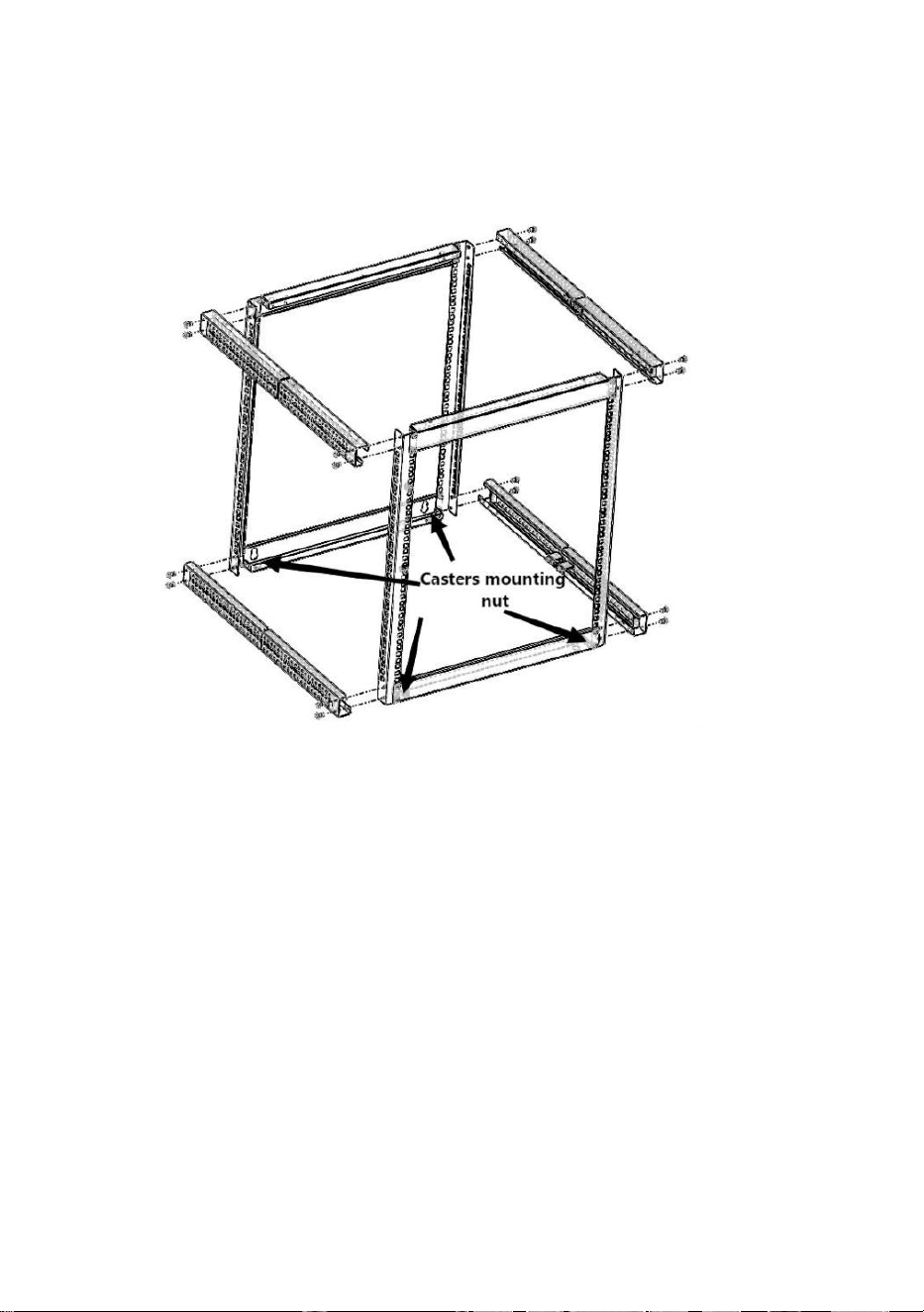
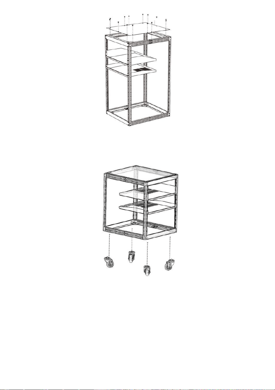
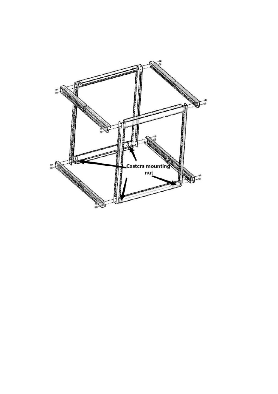
Assemble the Rack
1. Assembly Front Frame(①),Rear Frame②,Side
Sections(
③),
Secure with 16pcs M5*10 Cross head screws(⑧).
(Figure 5)
Figure 5
Notes:During assembly,need notice Front Frame(①)and Read
Frame(②)’s Direction,make sure the side with Casters
mounting nuts(white one on the inside of Left lower Bracket(#3)
and Right lower Bracket(#7)) on the bottom,the side without
nuts on the top.
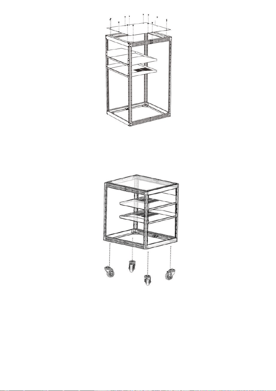
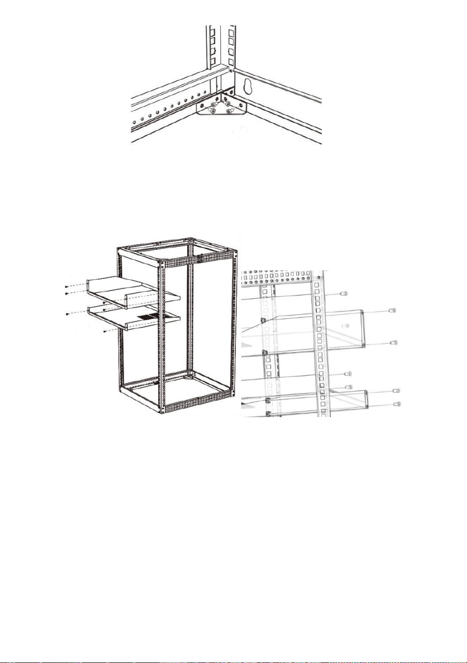
2. Place Corner piece (④) on the corner of Front
Frame(
①)
,Rear Frame
②
,Side Sections(
③)
.There are 8 locations
that need to be installed.Secure with 4pcs M5*10 Cross head
screws(⑧) on each Corner piece
(
④
) .
(Figure 6).
- 11 -
(Figure 6)
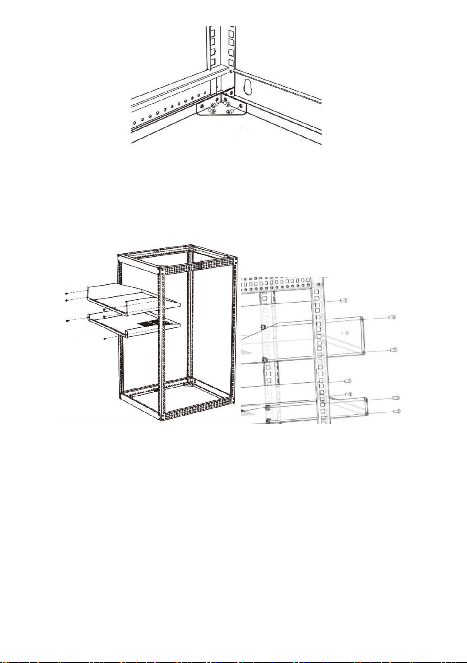
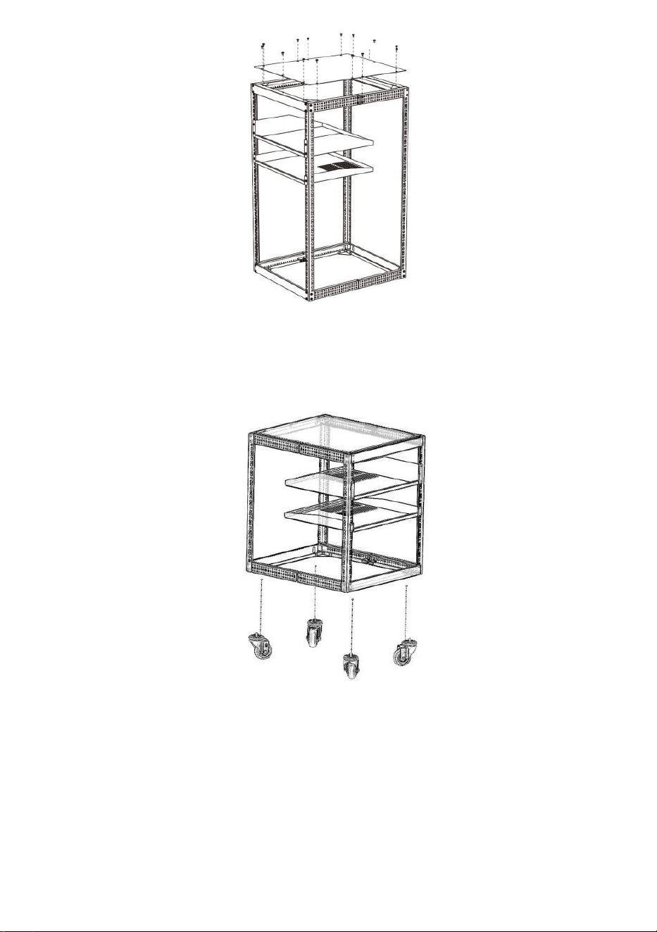
3. Place Top Pallet (⑥) and Bottom Pallet (⑦) on the Enclosure.
Secure with the 8pcs M6 Cage Nuts( ⑨ ) and 8pcs M6*12 Hex head
screws(⑩) by allen key.(Figure 7).
(Figure 7)
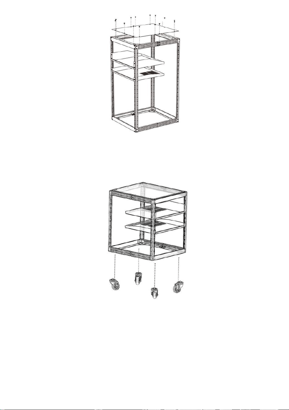
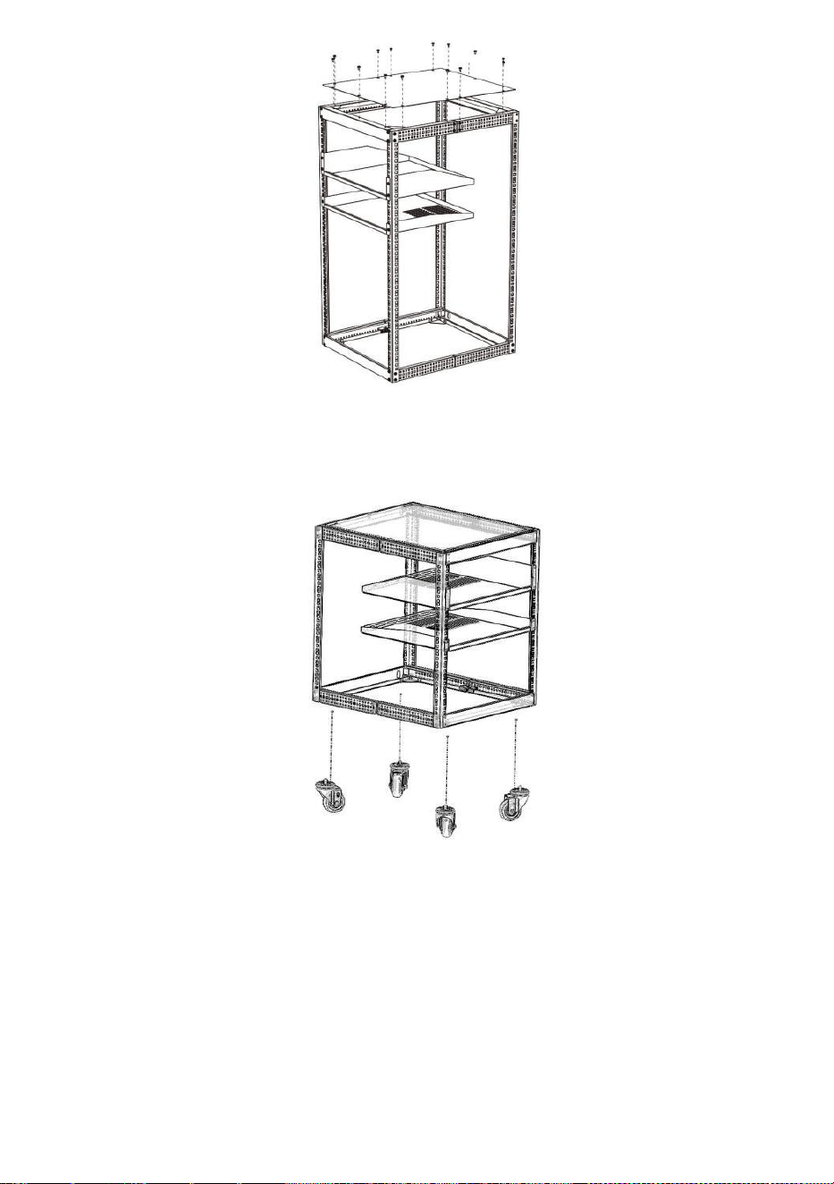
4. Place Top panel (⑤) on the Enclosure.Secure with 14pcs M5*10
Cross head screws(⑧) on the Top panel using Electric screwdriver.
(Figure 8).
- 12 -
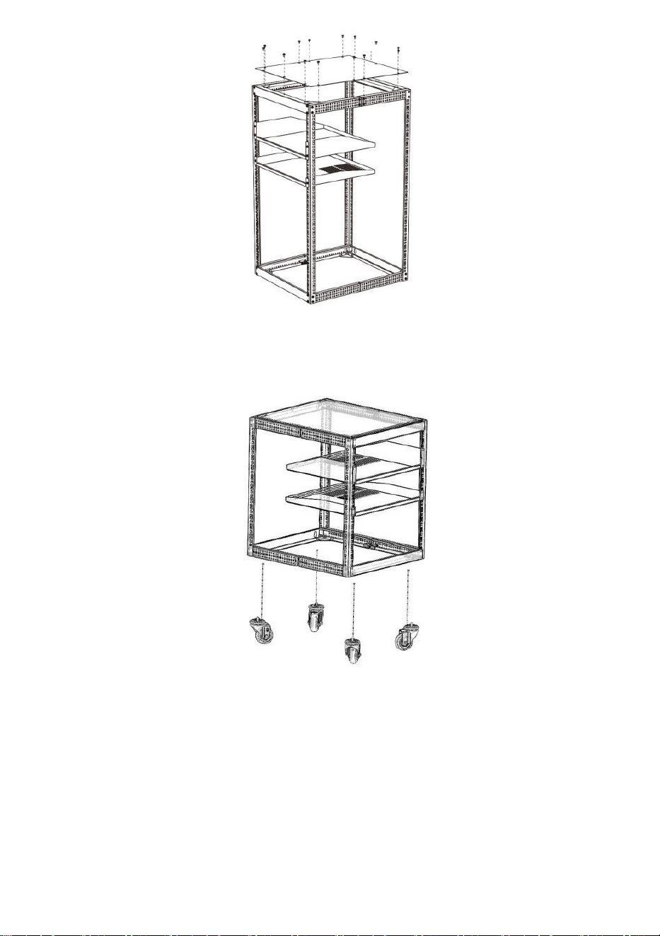
(Figure 8)
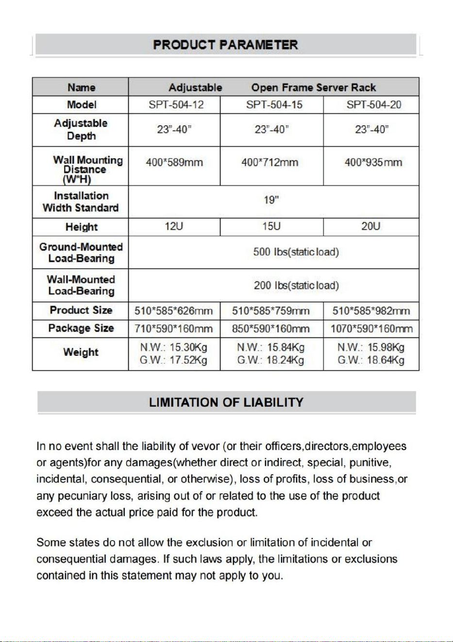
5. Place Casters(⑫)on the bottom of the rack,screw them with the rack’s
bottom nuts.Tighten them by 14mm spanner.(Figure 9).
(Figure 9)
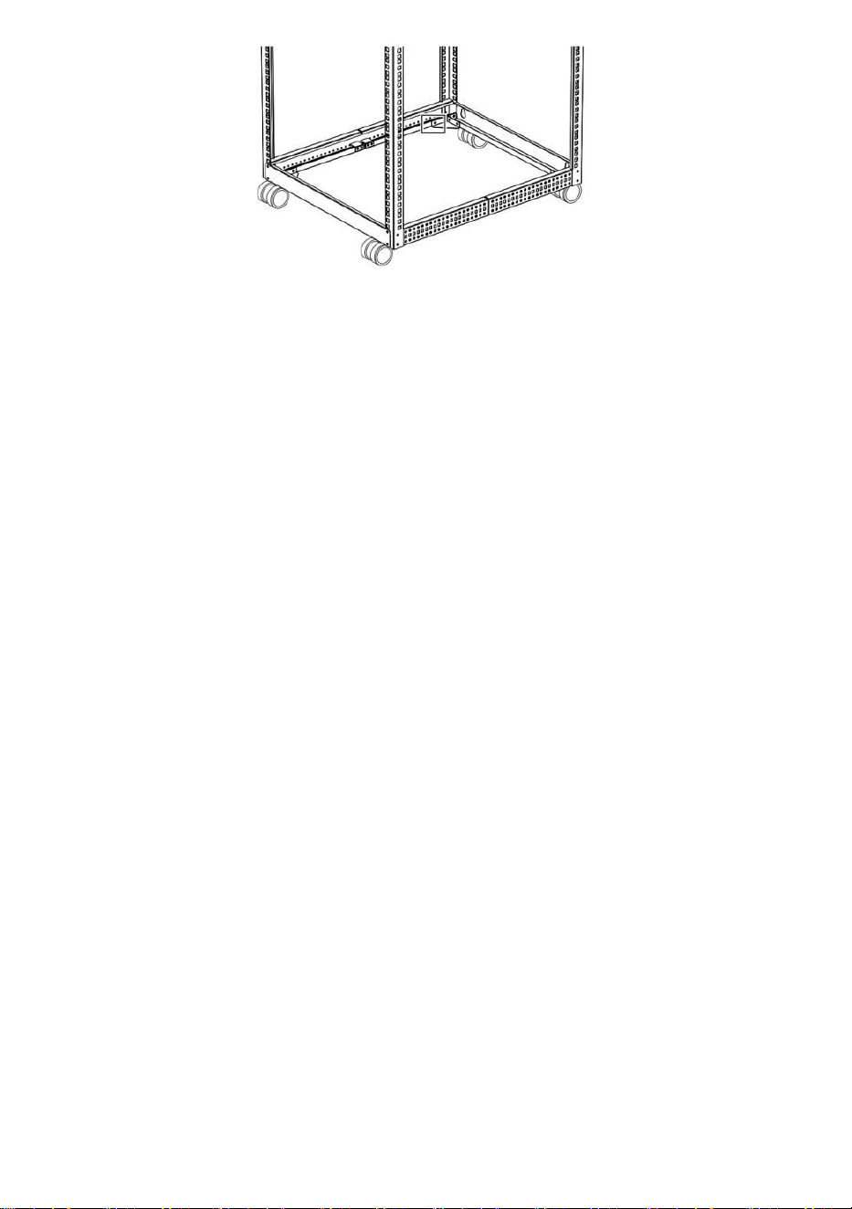
Ground the Rack
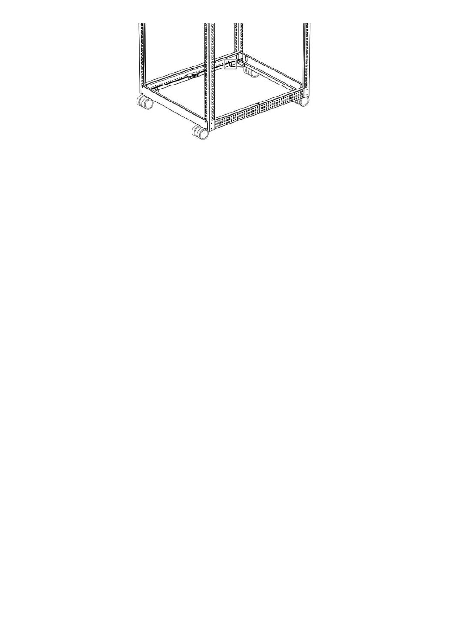
1. Insert an M5*10 Cross head screws(⑧) through the Grounding
Point on the Grounding Wire(⑬) and into the Ground Hole located on
the bottom of the Rack.(Figure 10).
2. Run the Grounding Wire(
⑬
) under the Rack’s Frame.(Figure 10).
3. Connect the Grounding Wire(⑬) to an Earth Ground Connection.
- 13 -
(Figure 10)
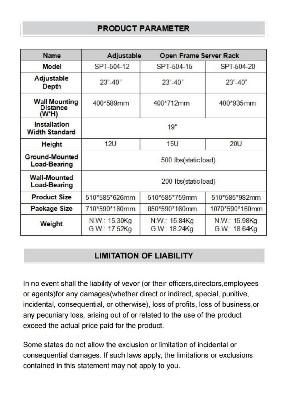
Wall Mounting the Rack
Attach the rack to a wall or other suitable mounting surface using M10*70
Expansion screws(
⑪
). The mounting hole distance is shown in the
following PRODUCT PARAMETER, apart to accommodate standard stud
placement as reflected in the diagram.
Warning: Do not attempt to mount to wall when equipment is mount-
ed inside the rack. The rack has a weight capacity of 200 pounds.
Make sure the type of wall structure and mounting hardware that you
are using will properly support the weight of the enclosure and
equipment.

- 14 -

- 14 -
Technical Support and E-Warranty Certificate
www.vevor.com/support
Made In China

- 14 -
Support technique et Certificat de garantie électronique
www.vevor.com/support
RÉGLABLE OUVRIR CADRE
SERVEUR ÉTAGÈRE
UTILISATEUR MANUEL
Nous continuons à nous engager à vous fournir des outils avec compétitif prix.
"Sauvegarder Moitié", "Moitié Prix" ou toute autre expression similaire utilisé par nous
seulement représente une estimation
des économies que vous pourrait bénéficier de acheter certains outils chez nous par rapport
à la haut majeur marques
et fait pas nécessairement entend couvrir toutes les catégories d'outils proposés par nous.
Toi sont gentiment
rappelez-vous de vérifier attentivement lorsque vous passez une commande avec nous si
vous êtes réellement économie moitié
en comparaison avec le sommet grandes marques.

ADJUSTABLE OPEN
FRAM SERVER RACK
THIS MANUAL APPLIES TO THE FOLLOWING SKUS:
HT-W6412 HT-W6415 HT-W6420
- 14 -
BESOIN DE L'AIDE? CONTACT NOUS!
Avoir Des questions sur les produits ? Besoin d'assistance technique
? N'hésitez pas à contact nous:
Support technique et Certificat de garantie
www.vevor.com/support
Ce est l'original instructions , s'il te plaît lire tout manuel instructions
soigneusement avant l'opération. VEVOR réserve un clair interprétation
de
notre manuel d'utilisation. L'apparence du produit devoir être soumis à
la produit vous reçu. Veuillez nous pardonner de ne plus vous informer
s'il y a des mises à jour technologiques ou logicielles sur notre produit.

ADJUSTABLE OPEN
FRAM SERVER RACK
THIS MANUAL APPLIES TO THE FOLLOWING SKUS:
HT-W6412 HT-W6415 HT-W6420
- 14 -
- 1 -

- 2 -
Remercier toi pour achat le Performance Séries murales Monter
Armoire de VEVOR.
Tous les efforts ont été faits pour assurer la précision de la information
dans ce produit manuel.
COMPLIANCE STATEMENTS
Utilisation des marques commerciales, des marques déposées
et d'autres marques protégées Noms et symboles
Ce manuel peut faire référence à des marques déposées, des marques
déposées
marques et autres marques protégées noms et/ou symboles de
sociétés tierces pas en rapport dans n'importe lequel chemin à vevor .
Où ils se produire ces référer - Les références sont à titre illustratif à
des fins uniquement et ne pas représenter un
approbation d'un produit ou service de vevor, ou un approbation de
le produit(s) auquel(auxquels) cela le manuel s'applique par la
société tierce en question. Indépendamment de toute reconnaissance
directe ailleurs dans le corps de ce document, vevor reconnaît par
la présente que tous les échanges- marques, marques déposées,
service marques et autres protégé
noms et/ou symboles contenus dans ce manuel et d docu- Les
éléments sont les propriété de leurs respectifs détenteurs.
WARNING STATEMENTS
Assurez-vous d' assembler ceci produit selon le instructions. Faire ne
pas dépasser la capacité de poids de ce produit. Surcharge ce
produit pourrait résultat dans blessures ou dommages matériels.
Ceci le produit peut prendre en charge le suivant Poids : Fixé au
sol charge portante : 500 lb , montage mural portant : 200
livres

- 2 -
Ce produit est destiné à un usage intérieur uniquement et doit
pas être utilisé en plein air.
Cette enceinte est extrêmement lourd. N'essayez jamais de déplacer ou
soulever ceci

- 3 -
:
enceinte sans assistance .
Pourboire danger! Extension plusieurs composants de ce boîtier
augmente le chance que le enceinte volonté conseil plus de . À éviter ce
risque , ne pas prolonger plus d' un composant depuis le enceinte.
Faire pas placer n'importe quel éléments sur cette enceinte et faire ne
pas empiler les enceinte sur un autre enceinte.
Garder liquide loin de cela enceinte.
Assurez-vous que vous installer le boîtier dans un zone que peut
poignée le poids combiné du boîtier et de la équipement que vous
avoir l'intention à placer à l'intérieur du Enclos .
Ce produit nécessite un terre - sol connexion . Faire pas utiliser ce
produit sans connexion à la terre .

PRODUCT DIAGRAM
- 4 -
Vue élargie

- 5 -
CONTENU DU COLIS
1
Devant
Quantité
de cadre
: 1
2
Arrière
Quantité
de cadre
: 1
③
Sections
latérales
Qté : 4
④
Pièce
d'angle
Qté : 8
- 6 -
5
6
Haut
Quantit
é de
palette :
1
Haut
Quantité
de
pannea
ux : 1
7
Bas Quantité
de
palette :
1
8
Croix M5*10 Tête Vis Qté :
80
9
10
Cage M6 Noix
Qté: 16
M6*12 hexagonal Tête
Vis Qté : 16
11
12
Roulett
es Qté
: 4
M10*70 mm Expansion Vis
Qté : 4
- 6 -
13
Fil de terre Qté
: 1

- 7 -
REQUIREMENTS
• Tournevis électrique (vendu séparément)
• Deux Les gens (pour l'assemblée)
• Allen clé (le paquet de pièces contient compris)
• Clé de 14 mm (pack de pièces) a compris)
Remarque : Deux les gens sont requis pour le Assemblage de rack.
- 8 -
Réglez le Montage Profondeur
1. Alignez les raquettes du coin gauche B (#4) et celles du coin droit
coin Supports (#4) avec les sections centrales (#8), faites glisser les
supports d'angle sur le dessus du Sections centrales. (Figure 1)
2. Déterminer le montage maximal requis profondeur pour le
Étagère Équipement montable.
3. Faites glisser les supports du coin gauche et le coin droit coin
Supports, vers l'intérieur le long des sections centrales et alignez les
sections centrales avec le trou sur les crochets du coin gauche et le
coin droit coin Supports.(Figure 2)
4. Fixez avec 4 pièces M5*10 vis à tête cruciforme ( ⑧ ) à travers
dans le trous dans les supports d'angle et Centre Sections.
(Chiffre 3)
4. Placez deux pièces de limite (#13) sur les supports d'angle ,
serrez les M5*10 Vis à tête cruciforme ( ⑧ ) à l'aide d'un tournevis
électrique. (Figure 4)
5. Répétez les étapes ci-dessus et assemblez les 4 autres sections
centrales .

- 9 -
Remarque : comme le montre le contenu de l'emballage ci-dessus
Sections ( ③) , nous avons déjà assemblé Supports de coin
gauche (#4), le Coin droit Supports (#5), les sections centrales
(#8) et Limite
pièces (#13) bien base une la profondeur minimale 23” (le étagère
la profondeur réglable est de 23" à 40"), vous pouvez garder
il s'il n'y a pas besoin modifier la profondeur.
Vous pouvez également modifier la profondeur en revenant à
N°4 processus,desserrer les 4 vis à tête cruciforme M5*10 ( ⑧ )
et ajustez la profondeur que vous besoin, et refixez avec les 4
vis à tête cruciforme M5 * 10 ( ⑧ ).

- 10 -
Assembler le Étagère
1. Assemblage Devant Cadre ( ①) , cadre arrière ②,Côté
Sections ( ③), Fixez avec 16 pièces M5*10 vis à tête cruciforme (
⑧ ).
(Chiffre 5)
Chiffre 5
Remarques : Lors de l'assemblage , il faut tenir compte de la
face avant Cadre ( ① ) et lecture Direction du cadre ( ② ),
assurez-vous que le côté avec les roulettes
montage noix (la blanche à l'intérieur de la gauche) inférieur
Support (#3) et à droite support inférieur (#7)) en bas, le côté
sans
noix sur le dessus.
2. Placez la pièce d'angle ( ④ ) sur le coin de la face avant
Cadre ( ①) , arrière Cadre ②,Section latérale s( ③).Il y en a 8
emplacements que besoin de être installé. Fixé avec 4 pièces M5*
10 Croix tête
vis ( ⑧ ) sur chaque pièce d'angle ( ④ ) . (Chiffre 6).

- 11 -
( Chiffre 6)
3. Lieu Haut Palette ( ⑥ ) et la palette inférieure ( ⑦ ) sur
l'enceinte. Sécurisé avec les 8 pièces Écrous à cage M6 ( ⑨ ) et 8 pièces
Tête hexagonale M6*12 vis ( ⑩ ) par Allen clé.( Figure 7).
(Chiffre 7)
4. Placez le haut panneau ( ⑤ ) sur le Enceinte.Sécurisé avec 14
pièces M5*10 Croix vis à tête ( ⑧ ) sur le dessus panneau en
utilisant Tournevis électrique. ( Chiffre 8).

- 12 -
(Chiffre 8)
5. Lieu Roulettes ( ⑫ ) sur le bas de le crémaillère , vis eux avec le fond
du rack écrous . Serrer eux par 14 mm clé . ( Figure 9).
(Chiffre 9)
Mettre à la terre le Étagère
1. Insérer un Croix M5*10 vis à tête ( ⑧ ) à travers la mise à la terre
Point sur le Fil de mise à la terre ( ⑬ ) et dans le sol Trou situé sur le
bas de la Rac k. (Figure 10).
2. Faites passer le fil de mise à la terre (
⑬
) sous le Rack Encadre-
moi. (Figure 10).
3. Connectez le fil de terre (
⑬
) à une Terre Sol Connexion.
- 13 -
(Chiffre 10)
Montage mural du Étagère
Fixez le support à un mur ou à un autre support approprié. surface de
montage en utilisant M10*70 Vis d'expansion (
⑪
). Le la distance du
trou de montage est montré dans le
suivant PRODUIT PARAMETRE R, à part pour accueillir un goujon
standard placement comme reflété dans le diagramme.
Avertissement: N'essayez pas de monter l'équipement sur un mur.
est monter- édité à l'intérieur du rack. Le étagère a une capacité de
poids de 200 livres.
Assurez-vous du type de structure murale et du matériel de montage
que vous
utiliseront correctement supporteront le poids de l'enceinte et
équipement.
- 14 -

- 14 -
Support technique et Certificat de garantie
électronique www.vevor.com/support
Fait En Chine

- 14 -
Technischer Support und E-Garantie-Zertifikat www.vevor.com/support
EINSTELLBAR OFFEN RAHMEN
SERVER GESTELL
BENUTZER HANDBUCH
Wir sind weiterhin bestrebt, Ihnen Werkzeuge mit wettbewerbsfähig Preis.
"Speichern Halb", "Halber Preis" oder andere ähnliche Ausdrücke gebraucht von uns nur
repräsentiert eine Schätzung
von Einsparungen Sie könnte profitieren von den Kauf bestimmter Werkzeuge bei uns im
Vergleich zu den Hauptspitze Marken
und tut nicht unbedingt bedeutet, alle angebotenen Werkzeugkategorien abzudecken von
uns. Sie Sind freundlich
Bitte überprüfen Sie sorgfältig, wenn Sie eine Bestellung aufgeben mit uns wenn Sie
tatsächlich Sparen Hälfte
im Vergleich zu den Top große Marken.

ADJUSTABLE OPEN
FRAM SERVER RACK
THIS MANUAL APPLIES TO THE FOLLOWING SKUS:
HT-W6412 HT-W6415 HT-W6420
- 14 -
BRAUCHEN HILFE? KONTAKT UNS!
Haben Fragen zum Produkt? Benötigen Sie technischen Support?
Bitte zögern Sie nicht, Kontakt uns:
Technischer Support und EGarantie-
Zertifikat www.vevor.com/support
Das ist das Original Anweisung , Bitte alles lesen Handbuch
Anweisungen
sorgfältig vor dem Betrieb. VEVOR behält sich eine klare Interpretation
von
unser Benutzerhandbuch. Das Aussehen des Produkts soll unterliegen
den Produkt Sie erhalten. Bitte entschuldigen Sie, dass wir Sie nicht

ADJUSTABLE OPEN
FRAM SERVER RACK
THIS MANUAL APPLIES TO THE FOLLOWING SKUS:
HT-W6412 HT-W6415 HT-W6420
- 14 -
noch einmal informieren werden ob es Technologie- oder Software-
Updates gibt auf unserer Produkt.
- 1 -

- 2 -
Dank du für Einkauf Die Leistung Serie Wand Montieren Kabinett von
VEVOR.
Es wurden alle Anstrengungen unternommen, um sicherzustellen, dass
Genauigkeit der Information In Das Produkt Handbuch.
COMPLIANCE STATEMENTS
Verwendung von Warenzeichen, eingetragenen Warenzeichen
und anderen geschützten Namen und Symbole
Das Handbuch Mai auf Marken, eingetragene Warenzeichen oder
Marken und andere geschützte Namen und/oder Symbole von
Drittfirmen nicht verwandt In beliebig Weg Zu vevor . Wo Sie
geschehen diese verweisen - enzen dienen zur Veranschaulichung
nu r zu di es em Zweck und nicht darstellen ein
Billigung einer Produkt oder Dienstleistung von Vevor oder einem
Billigung von Die Produkt(e), auf das/die sich dieses Handbuch gilt
durch die Drittfirma in Frage. Unabhängig von einer direkten
Bestätigung an anderer Stelle In Die Hauptteil dieses Dokuments,
vevor erkennt hiermit an, dass alle Handels- Marken, eingetragene
Warenzeichen, Dienstleistungsmarken Marken und andere geschützt
Namen und/oder Symbole enthalten in diesem Handbuch und
zugehörige d dokumentieren ments sind die Eigentum ihrer
jeweiligen Inhaber.
WARNING STATEMENTS
Stellen Sie sicher, dass Sie dies zusammenbauen Produkt nach Die
Anweisungen. Tun nicht die Gewichtskapazität dieses Produkt.
Überladung Das
Produkt könnte Ergebnis In Personen- oder Sachschäden. Produkt
kann unterstützen Die folgende Gewicht : Bodenmontiert
Tragkraft : 500 Ib , Wandmontage tragend : 200 Pfund .

- 2 -
Das Produkt Ist nur für den Gebrauch in Innenräumen bestimmt und
sollte nicht Sei gebraucht draußen.
Dieses Gehäuse ist extrem schwer. Versuchen Sie niemals, bewegen
oder heben Sie diese

- 3 -
:
Gehäuse ohne Hilfe .
Kippen Gefahr! Erweitern mehrere Komponenten aus diesem Gehäuse
erhöht Die Chance Das Die Gehäuse Wille Tipp über . Zu vermeiden Das
Risiko , nicht verlängern mehr als eine Komponente aus Die Gehäuse.
Tun nicht Platzieren Sie Gegenstände auf diesem Gehäuse und nicht
stapeln die Gehäuse auf einem anderen Gehäuse.
Halten Flüssigkeit von diesem Gehäuse.
Stellen Sie sicher, dass Sie Installieren Sie das Gehäuse In ein
Bereich Das dürfen handhaben Die Gesamtgewicht des Gehäuses und
der Ausrüstung, die Sie beabsichtigen Zu Platz innerhalb der Gehäuse
.
Das Produkt erfordert ein Erde - Boden Verbindung . nicht verwenden
Das
Produkt ohne Erdungsanschluss .

PRODUCT DIAGRAM
- 4 -
Erweiterte Ansicht
- 5 -
PACKUNGSINHALT
1
Front
Rahmen
menge :
1
2
Hinteren
Rahmen
menge
: 1
③
Seitenteile
Menge : 4
④
Eckstück
Menge :
8

- 6 -
5
6
Spitze
Palette
nmeng
e : 1
Spitze
Anzahl
der
Panels :
1
7
Unten
Paletten
menge
: 1
8
M5*10 Kreuz Kopf
Schrauben
Menge : 80
9
10
M6 Käfig
Nüsse
Menge:
16
M6*12 Sechskant Kopf
Schrauben
Menge: 16
11
12
Anzahl
Rollen
: 4
M10*70 mm Erweiterung
Schrauben
Menge : 4

- 6 -
13
Erdungskabel
Menge : 1

- 7 -
REQUIREMENTS
• Elektrischer Schraubendreher ( separat erhältlich)
• Zwei Personen (für die Montage)
• Allen Schlüssel (Teilepaket hat enthalten)
• 14mm Schraubenschlüssel (Teilepaket hat enthalten)
Hinweis: Zwei Menschen sind erforderlich für die Rack-Montage.

- 8 -
Legen Sie die Montage Tiefe
1. Richten Sie die linke Eckhalterung (#4) und die rechte Ecke
Klammern (#4) mit den Mittelteilen (#8), schieben Sie die
Eckhalterungen über die Mittelabschnitte. (Abbildung 1)
2. Bestimmen Sie die maximal erforderliche Montage Tiefe für
die Gestell Montierbare Ausrüstung.
3. Schieben Sie die linken Eckklammern und die rechten Ecke
Klammern,nach innen entlang der Mittelabschnitte und richten Sie die
Mittelabschnitte mit dem Loch aus in der linken Ecke Klammern und
in der rechten Ecke Ecke Klammern. (Abbildung 2)
4. Sichern Sie mit 4 Stück M5*10 Kreuzschlitzschrauben ( ⑧ )
durch hinein Die Löcher in den Eckhalterungen und Center
Abschnitte. (Figur 3)
4. Platzieren Sie zwei Begrenzungsteile (#13) auf den
Eckhalterungen , ziehen Sie die M5*10 Kreuzschlitzschrauben ( ⑧ )
mit einem elektrischen Schraubendreher . (Abbildung 4)
5. Wiederholen Sie die obigen Schritte und montieren Sie die anderen 4
Mittelteile .

- 9 -
Hinweis: wie oben gezeigt verpackung inhalt Seite
Abschnitte ( ③) , die wir bereits zusammengebaut haben Linke
Eckklammern (#4), die Rechte Ecke Klammern (#5), die
Mittelteile (#8) und Limit
Teile (Nr. 13) gut Basis eine die Mindesttiefe 23”(die Gestell
einstellbare Tiefe ist 23"~40"), Sie können halten Es wenn es
keine brauchen die Tiefe ändern.
Sie können die Tiefe auch ändern, indem Sie auf Nr.4 Prozess,
lösen Die 4 Kreuzschlitzschrauben M5*10 ( ⑧ ) und stellen Sie
die gewünschte Tiefe ein. und befestigen Sie es bei Bedarf
erneut mit den vier M5 x 10 Kreuzschlitzschrauben ( ⑧ ).
- 10 -
Montieren Sie die Gestell
1. Montage Front Rahmen ( ①) , Hinterer Rahmen ②,Seite
Abschnitte ( ③), Sichern mit 16 Stück M5*10 Kreuzschlitzschrauben
( ⑧ ).
(Figur 5)
Figur 5
Hinweise: Während der Montage , müssen Sie beachten Front
Rahmen( ① )und Lesen Rahmenrichtung ( ② ), achten Sie
darauf, dass die Seite mit den Rollen
Montage Muttern (weiße auf der Innenseite der linken untere
Klammer (#3) und rechts untere Halterung (#7)) an der
Unterseite, der Seite ohne
Nüsse oben drauf.
2. Platzieren Sie das Eckstück ( ④ ) an der Ecke der Vorderseite
Rahmen (
①)
, Hinten Rahmen
②
,Seitenabschnitte (
③)
.Es gibt
8 Standorte Das müssen Sei Mit 4 Stück M5* sichern.10 Kreuz
Kopf
Schrauben ( ⑧ ) an jedem Eckstück ( ④ ) . (Figur 6).

- 11 -
( Figur 6)
3. Ort Spitze Palette ( ⑥ ) und untere Palette ( ⑦ ) An das
Gehäuse. Sicher mit die 8St M6 Käfigmuttern ( ⑨ ) und 8 Stück M6*12
Sechskantkopf Schrauben ( ⑩ ) von allen Taste.( Abbildung 7).
(Figur 7)
4. Top platzieren ( ⑤ ) auf der Gehäuse. Sicher mit 14 Stück M5*10
Kreuzen Kopfschrauben ( ⑧ ) auf der Oberseite Bedienfeld mit
Elektrischer Schraubendreher. ( Figur 8).

- 12 -
(Figur 8)
5. Ort Rollen ( ⑫ ) auf Die unten von Die Gestell , Schraube ihnen mit
Die Rack - Unterseite Muttern . Festziehen ihnen von 14 mm
Schraubenschlüssel ( Abbildung 9) .
(Figur 9)
Erden Sie die Gestell
1. Einfügen eines M5*10 Kreuz Kopfschrauben ( ⑧ ) durch den
Erdungsanschluss
Punkt auf dem Erdungskabel ( ⑬ ) und in den Boden Loch an Die
Unterseite des Rac k. (Abbildung 10).
2. Führen Sie das Erdungskabel ( ⑬ ) unter dem Racks Rahmen Sie
mich ein. (Abbildung 10).

- 12 -
3. Verbinden Sie das Erdungskabel ( ⑬ ) mit einem Erde Boden
Verbindung.

- 13 -
(Figur 10)
Wandmontage des Gestell
Befestigen Sie das Rack an einer Wand oder einem anderen geeigneten
Montagefläche mit M10*70 Dehnschrauben(
⑪
). Die Der Abstand der
Befestigungslöcher beträgt gezeigt im
folgende PRODUKT PARAMETER R, auseinander, um Standardbolzen
aufzunehmen Platzierung als im Diagramm wiedergegeben.
Warnung: Versuchen Sie nicht, das Gerät an der Wand zu befestigen,
wenn Ist montieren- Ed. im Rack. Die Gestell hat eine
Gewichtskapazität von 200 Pfund.
Stellen Sie sicher, dass die Art der Wandstruktur und die
Montagehardware , die Sie verwenden,
verwenden, das Gewicht des Gehäuses ausreichend tragen
kann und Ausrüstung.

- 14 -

- 14 -
Technischer Support und E- Garantie-
Zertifikat www.vevor.com/support
Gemacht In China

- 14 -
Supporto tecnico e Certificato di garanzia elettronica
www.vevor.com/support
REGOLABILE APRIRE TELAIO
SERVER Cremagliera
UTENTE MANUALE
Continuiamo a impegnarci per fornirti strumenti con competitivo prezzo.
"Salva "Metà", "Metà prezzo" o altre espressioni simili usato di solo noi rappresenta una
stima
di risparmi tu Potrebbe beneficiare di acquistando determinati strumenti con noi rispetto al
cima maggiore marche
e fa non necessariamente intende coprire tutte le categorie di strumenti offerti di noi. Tu
Sono gentilmente
ricordati di verificare attentamente quando effettui un ordine con noi se sei realmente
risparmio metà
rispetto al top grandi marchi.

ADJUSTABLE OPEN
FRAM SERVER RACK
THIS MANUAL APPLIES TO THE FOLLOWING SKUS:
HT-W6412 HT-W6415 HT-W6420
- 14 -
BISOGNO AIUTO? CONTATTO NOI!
Avere domande sul prodotto? Hai bisogno di supporto tecnico? Non
esitate a contattarci contatto noi:
Supporto tecnico e Certificato di garanzia
elettronica
www.vevor.com/support
Questo è l'originale istruzione , Per favore leggi tutto manuale istruzioni
accuratamente prima di operare. VEVOR riserva una chiara
interpretazione di
il nostro manuale utente. L'aspetto del prodotto deve essere soggetto
a prodotto tu ricevuto. Per favore perdonaci se non ti informeremo più
se ci sono aggiornamenti tecnologici o software sul nostro prodotto.

ADJUSTABLE OPEN
FRAM SERVER RACK
THIS MANUAL APPLIES TO THE FOLLOWING SKUS:
HT-W6412 HT-W6415 HT-W6420
- 14 -
- 1 -

- 2 -
Grazie tu per acquisto IL Prestazione Serie Muro Montare Mobiletto
da VEVOR.
Sono stati fatti tutti gli sforzi possibili per garantire la precisione del
informazioni In Questo prodotto manuale.
COMPLIANCE STATEMENTS
Utilizzo di marchi, marchi registrati e altri marchi protetti Nomi
e simboli
Questo manuale Maggio fare riferimento a marchi, marchi registrati
marchi e altri marchi protetti nomi e/o simboli di società terze non
imparentato In Qualunque modo A vevor . Dove Essi verificarsi questi
fare riferimento - le indicazioni sono a scopo illustrativo so lo scopi e
fare non rappresentare UN
approvazione di un prodotto o servizio di vevor, o un approvazione di
IL prodotto(i) a cui questo manuale applicato dalla società terza in
questione. Indipendentemente da qualsiasi riconoscimento diretto
altrove In IL corpo di questo documento, vevor riconosce con la
presente che tutto il commercio- marchi, marchi registrati, servizi
marchi e altro protetto
nomi e/o simboli contenuti in questo manuale e correlato d
documentare gli elementi sono i proprietà dei rispettivi titolari.
WARNING STATEMENTS
Assicurati di assemblare questo prodotto secondo IL istruzioni. Fare
non superare la capacità di peso di questo prodotto. Sovraccarico
Questo
prodotto Potrebbe risultato In lesioni o danni alla proprietà. Questo
il prodotto può supportare IL seguente peso : montato a terra
Portata : 500 Ib , Montaggio a parete portante : 200 libbre .
Questo prodotto È destinato esclusivamente all'uso interno e
dovrebbe non Essere usato all'aperto.

- 2 -
Questo recinto è estremamente pesante. Non tentare mai di spostare o
sollevare questo

- 3 -
:
recinto senza assistenza .
Mancia pericolo! Estensione più componenti da questo recinto
aumenta IL opportunità Quello IL allegato Volere mancia oltre . A Evitare
Questo rischio , non estendere più di un componente da IL allegato.
Fare non posizionare qualsiasi articoli su questo allegato e fai non
impilare il allegato sopra un altro allegato.
Mantenere liquido lontano da questo allegato.
Assicurati di installare il contenitore In UN zona Quello Potere
maniglia IL peso combinato del recinto e del attrezzatura che tu
intendere A posizionare all'interno del allegare sicuro.
Questo prodotto richiede UN terra - terreno connessione . Fare non
utilizzo Questo
prodotto senza collegamento a terra .

PRODUCT DIAGRAM
- 4 -
Vista espansa
- 5 -
CONTENUTO DELLA CONFEZIONE
1
Davanti
Quantità
telaio : 1
2
Posteriore
Quantità
telaio : 1
③
Sezioni
laterali Qtà
: 4
④
Pezzo
d'angolo
Quantità
: 8
- 6 -
5
6
Superiore
Quantit
à pallet
: 1
Superiore
Pannell
o Qtà :
1
7
Metter il
fondo a
Quantità
pallet : 1
8
M5*10 Croce Testa Viti
Quantità : 80
9
10
Gabbia M6
Dadi
Quantità:
16
M6*12 Esagonale Testa
Viti Quantità: 16
11
12
Ruote
Quanti
tà : 4
M10*70 millimetri Espansione
Viti Quantità : 4

- 6 -
13
Filo di messa a
terra
Quantità :
1

- 7 -
REQUIREMENTS
• Cacciavite elettrico (venduto separatamente)
• Due Persone (per l'assemblaggio)
• Allen chiave (il pacchetto di parti ha incluso)
• Chiave inglese da 14 mm (pacchetto di parti) ha incluso)
Nota: due le persone sono richiesto per il Montaggio del rack.
- 8 -
Imposta il Montaggio Profondità
1. Allineare le staffe dell'angolo sinistro (#4) e quelle dell'angolo destro
angolo Parentesi(#4) con le sezioni centrali (#8), fai scorrere le staffe
angolari sopra la Sezioni centrali.(Figura 1)
2. Determinare il montaggio massimo richiesto profondità per il
Cremagliera Attrezzatura montabile.
3. Far scorrere le parentesi angolari di sinistra e di destra angolo
Parentesi, verso l'interno lungo le sezioni centrali e allineare le sezioni
centrali con il foro sulle parentesi angolari di sinistra e di destra
angolo Parentesi.(Figura 2)
4. Fissare con 4 pezzi M5*10 Viti a testa cruciforme ( ⑧ ) passanti
in IL fori nelle staffe angolari e Centro Sezioni. (Figura 3)
4. Posizionare due parti limite (#13) sulle staffe angolari , serrare
M5*10 Viti a testa a croce ( ⑧ ) utilizzando un cacciavite elettrico.
(Figura 4)
5. Ripetere i passaggi precedenti e assemblare le altre 4 sezioni centrali .

- 9 -
Nota: come mostrato nel contenuto dell'imballaggio sopra
Sezioni ( ③) , che abbiamo già assemblato Parentesi angolari
sinistre (#4) , Angolo destro Parentesi (#5), le sezioni centrali (#8)
e Limite
parti(#13)base del pozzo una profondità minima 23”(il scaffale
la profondità regolabile è 23 "~ 40"), puoi Mantenere Esso se
non c'è Bisogno modificare la profondità.
Puoi anche modificare la profondità tornando a Numero 4
processo, allentare le 4 viti a testa cruciforme M5*10 ( ⑧ ) e
regola la profondità necessario e fissare nuovamente con le 4
viti a testa croce M5*10 ( ⑧ ).

- 10 -
Montare il Cremagliera
1. Assemblaggio Davanti Telaio ( ①) , Telaio posteriore ②,Lato
Sezioni ( ③), Proteggi con 16 pezzi M5*10 Viti con testa a croce (
⑧ ).
(Figura 5)
Figura 5
Note: durante il montaggio , è necessario notare la parte
anteriore Frame( ① )e Leggi Direzione del telaio ( ② ),
assicurarsi che il lato con le rotelle
montaggio noci (quella bianca all'interno di sinistra) inferiore
Staffa(#3) e giusto staffa inferiore (#7)) sul fondo, il lato senza
noci in cima.
2. Posizionare il pezzo d'angolo ( ④ ) sull'angolo anteriore
Telaio (
①)
, posteriore Telaio
②
,Sezione laterale s(
③)
.Ci sono
8 Luoghi Quello bisogno di Essere installato. Fissare con 4 pezzi
M5*10 Croce Testa
viti ( ⑧ ) su ogni pezzo d'angolo
(
④
) .
(Figura 6).

- 11 -
( Figura 6)
3. Posto Superiore Paletta ( ⑥ ) e pallet inferiore ( ⑦ ) SU il
recinto. Sicuro con gli 8 pezzi Dadi in gabbia M6 ( ⑨ ) e 8 pezzi M6*12
Testa esagonale viti ( ⑩ ) di Allen chiave.( Figura 7).
(Figura 7)
4. Posizionare la parte superiore pannello ( ⑤ ) sul Recinto. Sicuro
con 14 pezzi M5*10 Attraverso viti a testa ( ⑧ ) sulla parte superiore
pannello usando Cacciavite elettrico. ( Figura 8).
- 12 -
(Figura 8)
5. Posto Ruote ( ⑫ ) su IL metter il fondo a Di IL cremagliera , vite loro
con IL fondo del rack dadi . Stringere loro di 14 millimetri chiave inglese .
( Figura 9).
(Figura 9)
Mettere a terra il Cremagliera
1. Inserisci un M5*10 Croce viti a testa ( ⑧ ) attraverso la messa a
terra
Punto sul Cavo di messa a terra ( ⑬ ) e nel terreno Foro situato su
IL fondo del Rack (Figura) 10).
2. Far passare il filo di messa a terra ( ⑬ ) sotto il Il rack Incorniciami
.(Figura 10).

- 12 -
3. Collegare il filo di messa a terra ( ⑬ ) a un Terra Terra
Connessione.

- 13 -
(Figura 10)
Montaggio a parete del Cremagliera
Fissare il rack a una parete o a un altro supporto idoneo superficie di
montaggio usando M10*70 Viti di espansione (
⑪
). la distanza del foro
di montaggio è mostrato nel
seguente PRODOTTO PARAMETRO R, a parte per ospitare perno
standard posizionamento come riflesso nel diagramma.
Avvertimento: Non tentare di montare l'apparecchiatura a parete È
montare- ed all'interno del rack. Il scaffale ha una capacità di peso di
200 libbre.
Assicurati del tipo di struttura della parete e dell'hardware di
montaggio che utilizzi
che stanno utilizzando sosterranno adeguatamente il peso del
recinto e attrezzatura.

- 14 -

- 14 -
Supporto tecnico e Certificato di garanzia
elettronica www.vevor.com/support
Fatto In Cina

- 14 -
Soporte técnico y Certificado de garantía electrónica
www.vevor.com/support
AJUSTABLE ABIERTO MARCO
SERVIDOR ESTANTE
USUARIO MANUAL
Seguimos comprometidos a brindarle herramientas con competitivo precio.
"Ahorrar Mitad", "mitad de precio" o cualquier otra expresión similar usado por Sólo nosotros
representa Una estimación
de ahorros que usted podría beneficiarse de comprando ciertas herramientas con nosotros
en comparación con las cima mayor marcas
y lo hace no necesariamente pretende cubrir todas las categorías de herramientas
ofrecidas por Nosotros. Tú son amable
Se recuerda verificar cuidadosamente al realizar un pedido con a nosotros Si en realidad lo
eres ahorro medio
En comparación con la parte superior Grandes marcas.

ADJUSTABLE OPEN
FRAM SERVER RACK
THIS MANUAL APPLIES TO THE FOLLOWING SKUS:
HT-W6412 HT-W6415 HT-W6420
- 14 -
NECESIDAD ¿AYUDA? CONTACTO ¡A
NOSOTROS!
Tener ¿Preguntas sobre el producto? ¿Necesita soporte técnico?
Por favor, siéntete libre de contacto a nosotros:
Soporte técnico y Certificado de garantía
electrónica
www.vevor.com/support
Este es el original Instrucción , por favor leer todo manual instrucciones
con cuidado antes de operar. VEVOR se reserva un claro interpretación
de
Nuestro manual de usuario. La apariencia del producto deber estar
sujeto a la producto tu recibió. Por favor perdónanos por no informarte

ADJUSTABLE OPEN
FRAM SERVER RACK
THIS MANUAL APPLIES TO THE FOLLOWING SKUS:
HT-W6412 HT-W6415 HT-W6420
- 14 -
nuevamente Si hay alguna actualización de tecnología o software en
nuestro producto.
- 1 -

- 2 -
Agradecer Tú por adquisitivo el Actuación Serie Muro Montar
Gabinete de VEVOR.
Se ha hecho todo lo posible para garantizar la exactitud del información
en este producto manual.
COMPLIANCE STATEMENTS
Uso de marcas comerciales, marcas registradas y otras marcas
protegidas Nombres y símbolos
Este manual puede hacer referencia a marcas, nombres comerciales
registrados
marcas y otros elementos protegidos nombres y/o símbolos de
empresas de terceros no relacionado en cualquier forma a vevor .
Dónde ellos ocurrir estos referirse - Las referencias son para fines
ilustrativos. solo para propósitos y fines no representar un
respaldo de un producto o servicio de vevor, o un respaldo de el
producto(s) a los que se aplica este El manual lo aplica la empresa
de terceros. en cuestión. Independientemente de cualquier
reconocimiento directo en otra parte en el cuerpo de este
documento, vevor Por la presente reconoce que todo comercio-
marcas, marcas registradas, servicio marcas y otros protegido
nombres y/o símbolos contenidos En esto Manual y relacionados
documento- Los mentos son los propiedad de sus respectivos
titulares.
WARNING STATEMENTS
Asegúrese de ensamblar esto producto según el instrucciones. Hacer
No exceda la capacidad de peso de este producto. Sobrecarga este
producto podría resultado en lesiones o daños a la propiedad. Esto
El producto puede soportar el siguiente Peso : Montado en el suelo
Capacidad de carga : 500 lb , montado en la pared soportando
carga : 200 libras .

- 2 -
Este producto es destinado únicamente para uso en interiores y
debe no ser usado al aire libre.
Este recinto es extremadamente pesado. Nunca intentes mover o levantar
esto

- 3 -
:
recinto sin asistencia .
Propinas ¡peligro! Extensión Múltiples componentes de este gabinete
aumenta el oportunidad eso el recinto voluntad consejo Más de . evitar
este riesgo , no extenderse más de un componente de el recinto.
Hacer no Coloque cualquier elementos de este gabinete y hacer No
apilar el recinto Encima de otro recinto.
Mantener líquido lejos de este recinto.
Asegúrate de que Instalar el gabinete en un área eso poder manejar
el peso combinado del recinto y el equipo que usted pretender a
colocar dentro de la adjuntar .
Este producto requiere un tierra - suelo conexión . Hacer no usar este
producto sin conexión a tierra .
PRODUCT DIAGRAM
- 4 -
Vista ampliada
- 5 -
CONTENIDO DEL PAQUETE
1
Frente
Cantida
d de
marcos :
1
2
Trasero
Cantidad
de
marcos :
1
③
Secciones
laterales
Cantidad :
4
④
Pieza de
esquina
Cantida
d : 8
- 6 -
5
6
Arriba
Cantida
d de
paletas
: 1
Arriba
Cantida
d de
paneles
: 1
7
Abajo
Cantidad
de
paletas :
1
8
M5*10 Cruz Cabeza
Tornillos
Cantidad : 80
9
10
Jaula M6
Nueces
Cantidad:
16
M6*12 Hexagonal
Cabeza
Tornillos
Cantidad: 16
11
12
Ruedas
Cantid
ad : 4
M10*70 mm Expansión
Tornillos
Cantidad : 4
- 6 -
13
Cable de
puesta a
tierra
Cantidad :
1

- 7 -
REQUIREMENTS
• Destornillador eléctrico (se vende por separado)
• Dos Pueblo (para asamblea)
• Allen llave (el paquete de piezas tiene incluido)
• Llave de 14 mm (paquete de piezas) tiene incluido)
Nota: Dos La gente es requerido para el Montaje en bastidor.
- 8 -
Establecer el Montaje Profundidad
1. Alinee los soportes de la esquina izquierda (#4) y los de la esquina
derecha. esquina Corchetes (#4) Con las secciones centrales (#8),
deslice los soportes de esquina sobre la parte superior de la
Secciones centrales.(Figura 1)
2. Determine el montaje máximo requerido profundidad para el
Estante Equipo montable.
3. Deslice los soportes de las esquinas izquierda y derecha. esquina
Soportes, hacia adentro a lo largo de las secciones centrales y alinee
las secciones centrales con el orificio en los soportes de la esquina
izquierda y la derecha esquina Soportes.(Figura 2)
4. Asegure con 4 piezas M5*10 Tornillos de cabeza cruzada ( ⑧ )
a través en el agujeros en los soportes de esquina y Centro
Secciones. (Cifra 3)
4. Coloque dos piezas de límite (#13) en los soportes de esquina y
apriete. M5*10 Tornillos de cabeza cruzada ( ⑧ ) usando
destornillador eléctrico . (Figura 4)
5. Repita los pasos anteriores y ensamble las otras 4 secciones centrales.

- 9 -
Nota: como se muestra en el contenido del embalaje anterior, lado
Secciones ( ③) , ya las hemos ensamblado Soportes de
esquina izquierda (#4), el Esquina derecha Soportes (#5), las
secciones centrales (#8) y Límite
partes(#13)pozo base uno la profundidad mínima 23”(el estante
La profundidad ajustable es de 23”~40”), puede mantener él
Si no hay necesidad modificar la profundidad.
También puedes modificar la profundidad volviendo a N°4
proceso, aflojar los 4 tornillos de cabeza cruzada M5*10 ( ⑧ ) y
ajuste la profundidad que desee. Necesita y vuelva a asegurar
con los 4 tornillos de cabeza cruzada M5*10 ( ⑧ ).

- 10 -
Ensamble el Estante
1. Montaje Frente Marco ( ①) , Marco trasero ②,Lado
Secciones ( ③), Asegurar con 16 piezas M5*10 Tornillos de cabeza
cruzada ( ⑧ ).
(Cifra 5)
Cifra 5
Notas: Durante el montaje , es necesario avisar al frente.
Marco ( ① ) y lectura Dirección del marco ( ② ), asegúrese de
que el lado con ruedas
montaje nueces (una blanca en el interior del lado izquierdo)
más bajo Soporte (#3) y Derecha Soporte inferior (#7)) en la
parte inferior, el lado sin
nueces en la parte superior.
2. Coloque la pieza de esquina ( ④ ) en la esquina del frente
Marco ( ①) , Trasero Marco ②,Sección lateral s( ③)Hay 8
Ubicaciones eso Necesitar ser Instalado.Asegúrelo con 4 piezas
M5*10 Cruz cabeza
Tornillos ( ⑧ ) en cada pieza de esquina ( ④ ) . (Cifra 6).

- 11 -
( Cifra 6)
3. Lugar Arriba Paleta ( ⑥ ) y paleta inferior ( ⑦ ) en El Recinto.
Seguro con las 8 piezas Tuercas enjauladas M6( ⑨ ) y 8 piezas Cabeza
hexagonal M6*12 tornillos( ⑩ ) por allen Clave.( Figura 7).
(Cifra 7)
4. Coloque la parte superior panel ( ⑤ ) en el Recinto.Asegúrelo con
14 piezas M5*10 Cruz Tornillos de cabeza ( ⑧ ) en la parte superior
panel usando Destornillador eléctrico. ( Cifra 8).
- 12 -
(Cifra 8)
5. Lugar Ruedas ( ⑫ ) en el abajo de el estante , tornillo a ellos con el
parte inferior del rack Tuercas . Apretar a ellos por 14 milímetros llave
inglesa . ( Figura 9).
(Cifra 9)
Conecte a tierra el Estante
1. Insertar un M5*10 Cruz Tornillos de cabeza ( ⑧ ) a través de la
conexión a tierra
Punto en el Cable de puesta a tierra ( ⑬ ) y En el suelo Agujero
ubicado en el parte inferior de la Bastidor .(Figura 10).
2. Pase el cable de conexión a tierra ( ⑬ ) por debajo del Estantes
Enmarcame .(Figura 10).

- 12 -
3. Conecte el cable de conexión a tierra ( ⑬ ) a un Tierra Suelo
Conexión.

- 13 -
(Cifra 10)
Montaje en pared el Estante
Fije el estante a una pared u otro lugar adecuado. superficie de montaje
usando M10*70 Tornillos de expansión (
⑪
). Los La distancia del orificio
de montaje es mostrado en el
siguiente PRODUCTO PARÁMETRO R, aparte para acomodar pernos
estándar colocación como reflejado en el diagrama.
Advertencia: No intente montarlo en la pared cuando el equipo es
montar- ed dentro del rack. El estante Tiene una capacidad de peso
de 200 libras.
Asegúrese de que el tipo de estructura de pared y los herrajes de
montaje que va a utilizar sean los adecuados.
están utilizando soportarán adecuadamente el peso del
gabinete y equipo.
- 14 -

- 14 -
Soporte técnico y Certificado de garantía
electrónica www.vevor.com/support
Hecho En China

- 14 -
Wsparcie techniczne i Certyfikat gwarancji elektronicznej
www.vevor.com/support
NASTAWNY OTWARTE RAMA
SERWER STOJAK
UŻYTKOWNIK
PODRĘCZNIK
Nadal staramy się dostarczać Państwu narzędzia konkurencyjny cena.
"Ratować Połowa", "Połowa ceny" lub jakiekolwiek inne podobne wyrażenia używany przez
tylko my reprezentuje szacunek
oszczędności, które móc skorzystać z kupując u nas określone narzędzia w porównaniu do
główny szczyt marki
i robi nie koniecznie oznacza objęcie wszystkich kategorii oferowanych narzędzi przez nas.
Ty Czy uprzejmie
przypominamy o konieczności dokładnego sprawdzenia podczas składania zamówienia nas
jeśli naprawdę jesteś oszczędność połowa
w porównaniu z górą główne marki.
ADJUSTABLE OPEN
FRAM SERVER RACK
THIS MANUAL APPLIES TO THE FOLLOWING SKUS:
HT-W6412 HT-W6415 HT-W6420
- 14 -
POTRZEBOWAĆ POMOCY? KONTAKT NAS!
Mieć masz pytania dotyczące produktu? Potrzebujesz wsparcia
technicznego? Proszę, nie krępuj się kontakt nas:
Wsparcie techniczne i Certyfikat
gwarancyjny
www.vevor.com/support
Ten jest oryginałem instrukcja , Proszę przeczytaj wszystko podręcznik
instrukcje
ostrożnie przed operacją. VEVOR rezerwuje jasne interpretacja
nasza instrukcja obsługi. Wygląd produktu być podlegać produkt ty
otrzymane. Prosimy o wybaczenie, ale nie będziemy Cię już więcej
ADJUSTABLE OPEN
FRAM SERVER RACK
THIS MANUAL APPLIES TO THE FOLLOWING SKUS:
HT-W6412 HT-W6415 HT-W6420
- 14 -
informować czy są jakieś aktualizacje technologii lub oprogramowania
na naszym produkt.
- 1 -

- 2 -
Dziękować Ty za nabywczy ten Wydajność Seria Ściana Uchwyt
Gabinet od VEVOR.
Dołożyliśmy wszelkich starań , aby zapewnić dokładność z informacja
W Ten produkt podręcznik.
COMPLIANCE STATEMENTS
Korzystanie ze znaków towarowych, zarejestrowanych znaków
towarowych i innych chronionych znaków towarowych Nazwy i
symbole
Ten podręcznik móc odwoływać się do znaków towarowych,
zarejestrowanych znaków handlowych
znaki i inne chronione nazwy i/lub symbole firm trzecich nie
powiązany W każdy sposób Do vevor . Gdzie Oni zdarzać się te
wspominać - Informacje mają charakter poglądowy wy łą czn ie w
celach i nie reprezentować jakiś
poparcie dla produkt lub usługa firmy vevor lub poparcie ten
produkt(y), do których to dotyczy instrukcja obsługi jest obsługiwana
przez firmę zewnętrzną o którym mowa. Niezależnie od
jakiegokolwiek bezpośredniego potwierdzenia gdzie indziej W ten
treść tego dokumentu, vevor niniejszym potwierdzam, że cały handel-
znaki, zarejestrowane znaki towarowe, usługi znaki i inne chroniony
nazwy i/lub symbole zawarte w tym podręcznik i powiązane d
dokument- menty są własność ich poszczególnych posiadacze.
WARNING STATEMENTS
Upewnij się, że to zmontujesz produkt według ten instrukcje. Do nie
przekraczać dopuszczalnej masy tego produkt. Przeciążenie Ten
produkt móc wynik W obrażenia lub uszkodzenie mienia. To
produkt może obsługiwać ten następny waga : montaż na ziemi
nośność : 500 funtów , montaż na ścianie nośny : 200
funtów .

- 2 -
Ten produkt Jest przeznaczony wyłącznie do użytku wewnątrz
pomieszczeń i powinien nie Być używany na powietrzu.
Ta obudowa jest ex ekstremalnie ciężki. Nigdy nie próbuj przesuń lub
podnieś to

- 3 -
:
obudowa bez pomocy .
Napiwki zaryzykować! Rozsuwalny wiele komponentów z tej obudowy
zwiększa się ten szansa To ten załącznik będzie wskazówka ponad . Do
unikać Ten ryzyko , nie rozszerzaj więcej niż jeden składnik z ten
załącznik.
Do nie umieść dowolne elementy na tym załączniku i zrób nie układać w
stos załącznik na szczycie innego załącznik.
Trzymać płyn z dala od tego załącznik.
Upewnij się, że ty zainstaluj obudowę W jakiś obszar To Móc uchwyt
ten łączna waga obudowy i sprzęt , który ty zamierzać Do umieścić
wewnątrz załączam .
Ten produkt wymaga jakiś ziemia - grunt połączenie . Zrób nie używać
Ten
Produkt bez połączenia uziemiającego .
PRODUCT DIAGRAM
-4 -
Rozszerzony widok
- 5 -
ZAWARTOŚĆ OPAKOWANIA
1
Przód Ilość
ramek :
1
2
Tył Ilość
ramek : 1
③
Ilość sekcji
bocznych :
4
④
Element
narożny
Ilość : 8
- 6 -
5
6
Szczyt
Ilo ść
na
palecie
: 1
Szczyt
Ilość
paneli :
1
7
Spód Ilość
na
palecie :
1
8
M5*10 Krzyż Głowa Ilość
śrub : 80
9
10
Klatka M6
Ilość
orzechów
: 16
M6*12 Sześciokąt Głowa
Ilość śrub: 16
11
12
Ilość
kółek :
4
Śr. 10*70 mm Ekspansja
Śruby Ilość : 4
- 6 -
13
Przewód
uziemiając
y Ilość : 1

- 7 -
REQUIREMENTS
• Wkrętak elektryczny (sprzedawane oddzielnie)
• Dwa Ludzie (do montażu)
• Allen klucz (pakiet części ma dołączony)
• Klucz 14 mm (zestaw części) ma dołączony)
Uwaga: Dwa ludzie są wymagane dla Montaż stojaka.
- 8 -
Ustaw Montowanie Głębokość
1. Wyrównaj lewy narożnik B (#4) i prawy narożnik Uchwyty (#4) za
pomocą sekcji środkowych (#8) przesuń wsporniki narożne na górę
Sekcje środkowe.(Rysunek 1)
2. Określ maksymalną wymaganą wysokość montażu głębokość
dla Stojak Sprzęt montowany.
3. Przesuń lewy uchwyt narożny i prawy uchwyt narożny. narożnik
Wsporniki wewnętrzne wzdłuż sekcji środkowych i wyrównaj sekcje
środkowe z otworem w lewym narożniku uchwyty i prawym t narożnik
Uchwyty.(Rysunek 2)
4. Zabezpiecz 4 szt. M5*10 śrub z łbem krzyżakowym ( ⑧ ) do ten
otwory w uchwytach narożnych i Centrum Sekcje. (Postać 3)
4. Umieść dwie części ograniczające (#13) na wspornikach
narożnych i dokręć M5*10 Śruby z łbem krzyżakowym ( ⑧ ) przy
użyciu wkrętarki elektrycznej . (Rysunek 4)
5. Powtórz powyższe kroki i złóż pozostałe 4 sekcje środkowe.
- 9 -
Uwaga: jak pokazano powyżej, zawartość opakowania jest widoczna
z boku.
Sekcje ( ③) już zmontowaliśmy Lewy narożnik wspornika (#4),
Prawy róg Wsporniki (#5), sekcje środkowe (#8) i Limit
części (#13)dobrze ułóż jedną podstawę na minimalnej głębokości
23”(ten stojak
regulowana głębokość wynosi 23”~40”), możesz trzymać To
jeśli nie ma potrzebować zmodyfikuj głębokość.
Możesz również zmodyfikować głębokość, wracając do Nr 4
proces, poluzować 4 śruby krzyżakowe M5*10 ( ⑧ ) i wyreguluj
głębokość . należy ponownie zabezpieczyć za pomocą 4 śrub
M5*10 z łbem krzyżakowym (
⑧
).
- 10 -
Złóż Stojak
1. Montaż Przód Rama ( ①) , Rama tylna ②,Strona
Sekcje ( ③), Zabezpiecz za pomocą 16 szt. M5*10 śrub z łbem
krzyżakowym ( ⑧ ).
(Postać 5)
Postać 5
Uwagi: Podczas montażu należy zwrócić uwagę na przód
Ramka( ① )i odczyt Kierunek ramki ( ② ), upewnij się, że
strona z kółkami
montowanie orzechy (białe na wewnętrznej stronie lewej) niżej
Uchwyt (#3) i prawo dolny wspornik (#7) na dole, z boku bez
orzechy na górze.
2. Umieść element narożny ( ④ ) w rogu przodu
Rama (
①)
, Tył Ramka
②
,Sekcja boczna s(
③)
.Jest 8
lokalizacje To potrzebować Być zainstalowany. Zabezpiecz za
pomocą 4 śrub M5*10 Krzyż głowa
śruby ( ⑧ ) na każdym elemencie narożnym
(
④
) .
(Rysunek 6).

- 11 -
( Rysunek 6)
3. Miejsce Szczyt Paleta ( ⑥ ) i dolna paleta ( ⑦ ) NA Załącznik.
Bezpieczny z 8 sztuk Nakrętki klatkowe M6( ⑨ ) i 8szt. M6*12 Łeb
sześciokątny śruby( ⑩ ) przez allen klucz.( Rysunek 7).
(Postać 7)
4. Umieść górę panel ( ⑤ ) na Obudowa. Zabezpiecz za pomocą 14
szt. M5*10 Przechodzić śruby głowicy ( ⑧ ) na górze płyta używając
Wkrętak elektryczny. ( Rysunek 8).
- 12 -
(Postać 8)
5. Miejsce Koła ( ⑫ ) włączone ten spód z ten stojak , śruba ich z ten
dno stojaka orzechy . Dokręć ich przez 14 mm klucz . ( Rysunek 9).
(Postać 9)
Uziemić Stojak
1. Wstaw M5*10 Krzyż śruby głowicy ( ⑧ ) przez uziemienie
Punkt na Przewód uziemiający ( ⑬ ) i do ziemi Otwór zlokalizowany
na ten dno Stojak k.(Rysunek 10).
2. Przeprowadź przewód uziemiający (
⑬
) pod Stojak Fra
mnie.(Rysunek 10).
3. Podłącz przewód uziemiający (
⑬
) do Ziemia Grunt Połączenie.

- 13 -
(Postać 10)
Montaż na ścianie Stojak
Przymocuj stojak do ściany lub innego odpowiedniego miejsca.
powierzchnia montażowa używając M10*70 Śruby rozprężne (
⑪
).
odległość otworu montażowego wynosi pokazano w
następny PRODUKT PARAMETR R, oprócz dopasowania do
standardowych kołków umieszczenie jako odzwierciedlono na schemacie.
Ostrzeżenie: Nie próbuj montować urządzenia na ścianie, gdy Jest
uchwyt- wyd. wewnątrz stojaka. stojak ma udźwig 200 funtów.
Upewnij się, że rodzaj konstrukcji ściany i osprzęt montażowy, który
zamierzasz zamontować, jest odpowiedni.
będą prawidłowo podtrzymywać ciężar obudowy i sprzęt.
- 14 -

- 14 -
Wsparcie techniczne i Certyfikat E-War
www.vevor.com/support
Zrobiony W Chinach

- 14 -
Technische ondersteuning en E-garantiecertificaat
www.vevor.com/support
VERSTELBAAR OPEN KADER
SERVER REK
GEBRUIKER HANDMATIG
Wij blijven ons inzetten om u de tools te bieden die u nodig hebt competitief prijs.
"Redden Half", "Halve prijs" of andere soortgelijke uitdrukkingen gebruikt door alleen wij
vertegenwoordigt een schatting
van de besparingen die u macht profiteren van bepaalde gereedschappen bij ons kopen in
vergelijking met de grote top merken
en doet niet noodzakelijkerwijs betekent dat alle categorieën aangeboden tools worden
gedekt door wij. Jij Zijn vriendelijk
herinnerd om zorgvuldig te controleren wanneer u een bestelling plaatst bij ons als je
daadwerkelijk bent besparing half
in vergelijking met de top grote merken.

ADJUSTABLE OPEN
FRAM SERVER RACK
THIS MANUAL APPLIES TO THE FOLLOWING SKUS:
HT-W6412 HT-W6415 HT-W6420
- 14 -
BEHOEFTE HULP? CONTACT ONS!
Hebben productvragen? Technische ondersteuning nodig? Voel je
vrij om contact ons:
Technische ondersteuning en E-
garantiecertificaat
www.vevor.com/support
Dit is het origineel instructie , Alsjeblieft lees alles handmatig instructies
voorzichtig voor gebruik. VEVOR reserveert een duidelijke interpretatie
van
onze gebruikershandleiding. Het uiterlijk van het product zullen
onderworpen zijn aan de product jij ontvangen. Vergeef ons dat we u
ADJUSTABLE OPEN
FRAM SERVER RACK
THIS MANUAL APPLIES TO THE FOLLOWING SKUS:
HT-W6412 HT-W6415 HT-W6420
- 14 -
niet meer zullen informeren als er technologie- of software-updates zijn
op onze product.
- 1 -

- 2 -
Dank jij voor inkoop de Prestatie Serie Muur Berg Kastje van VEVOR.
Er is alles aan gedaan om ervoor te zorgen dat de nauwkeurigheid van
de informatie in dit product handmatig.
COMPLIANCE STATEMENTS
Gebruik van handelsmerken, geregistreerde handelsmerken en
andere beschermde Namen en symbolen
Dit handmatig kunnen verwijzen naar handelsmerken, geregistreerde
handels-
merken en andere beschermde namen en/ of symbolen van derde
partijen niet verwant in elk manier naar vevor . Waar zij voorkomen
deze refereren - ences zijn ter illustratie doeleinden alleen en doen
niet vertegenwoordigen een
goedkeuring van een product of dienst van vevor, of een goedkeuring
van de product(en) waarop dit betrekking heeft handleiding is van
toepassing door het derde bedrijf in kwestie. Ongeacht enige directe
erkenning elders in de hoofdtekst van dit document, vevor hierbij
erkennen wij dat alle handel- merken, geregistreerde handelsmerken,
service merken en andere beschermd
namen en/of symbolen die erin voorkomen in dit handleiding en
gerelateerde d document- ment zijn de eigendom van hun
respectievelijke houders.
WARNING STATEMENTS
Zorg ervoor dat je dit in elkaar zet product volgens de instructies. Doen
niet de draagkracht van dit gewicht overschrijden product.
Overbelasting dit
product macht resultaat in letsel of schade aan eigendommen. Dit
product kan ondersteunen de volgend gewicht : Op de grond
gemonteerd draagvermogen : 500 lb , wandmontage
lastdragend : 200 pond .

- 2 -
Dit product is uitsluitend bedoeld voor gebruik binnenshuis en mag
niet zijn gebruikt Buiten.
Deze behuizing is extreem zwaar. Probeer nooit om verplaats of til dit op

- 3 -
:
omheining zonder hulp .
Fooien geven gevaar! Uitbreiden meerdere componenten uit deze
behuizing
neemt toe de kans Dat de behuizing zullen tip over . Naar voorkomen dit
risico , niet verlengen meer dan één component van de omheining.
Doen niet plaats een items op deze behuizing en doe niet stapelen
behuizing bovenop een ander omheining.
Houden vloeistof weg van dit omheining.
Zorg ervoor dat je installeer de behuizing in een gebied Dat kan
hendel de gecombineerd gewicht van de behuizing en de apparatuur
die u van plan zijn naar plaats binnenin de omheining .
Dit product vereist een aarde - grond verbinding . Doen niet gebruik dit
product zonder aardverbinding .
PRODUCT DIAGRAM
- 4 -
Uitgebreide weergave
- 5 -
INHOUD VAN HET PAKKET
1
Voorkant
Frame
Hoeveel
heid : 1
2
Achterkant
Frame
Hoeveelh
eid : 1
③
Aantal
zijsecties :
4
④
Hoekstuk
Aantal :
8
- 6 -
5
6
Bovenkan
t
Hoevee
lheid
pallet :
1
Bovenkan
t Aantal
panelen
: 1
7
Onderkant
Hoeveel
heid
pallet : 1
8
M5*10 Kruis Hoofd
Schroeven Aantal
: 80
9
10
M6-kooi
Noten
Hoeveelh
eid: 16
M6*12 Zeskant Hoofd
Schroeven
Aantal: 16
11
12
Aantal
wielen
: 4
M10* 70mm Uitbreiding
Schroeven Aantal
: 4
- 6 -
13
Aardingsdraad
Aantal : 1
- 7 -
REQUIREMENTS
• Elektrische schroevendraaier (apart verkrijgbaar)
• Twee Mensen (voor de bijeenkomst)
• Allen sleutel (onderdelenpakket heeft inbegrepen)
• 14 mm sleutel (onderdelenpakket) heeft inbegrepen)
Let op: Twee mensen zijn vereist voor de Rekmontage.
- 8 -
Stel de Montage Diepte
1. Lijn de linkerhoek B -rackets (#4) en de rechterhoek B-rackets (#4)
uit hoek Haakjes (#4) met de middelste secties (#8), schuif de
hoekbeugels over de Centrale secties. (Figuur 1)
2. Bepaal de maximaal benodigde montage diepte voor de Rek
Monteerbare apparatuur.
3. Schuif de linkerhoekbeugels en de rechterhoekbeugels hoek
Haakjes, naar binnen langs de middelste secties en lijn de middelste
secties uit met het gat op de linkerhoek haakjes en de rechterhoek
haakjes hoek Haakjes. (Figuur 2)
4. Vastzetten met 4 stuks M5*10 Kruiskopschroeven ( ⑧ ) door
naar binnen de gaten in de hoekbeugels en Centrum Secties.
(Figuur 3)
4. Plaats twee Limit-onderdelen (#13) op de hoekbeugels en draai
de M5*10 Kruiskopschroeven ( ⑧ ) met behulp van een elektrische
schroevendraaier . (Figuur 4)
5. Herhaal de bovenstaande stappen en monteer de andere 4
middensecties .

- 9 -
Let op: zoals de bovenstaande verpakkingsinhoud laat zien Zijde
Secties ( ③) , we hebben ze al samengesteld Linkerhoek
haakjes (#4), de Rechterhoek Haakjes (#5), de middelste secties
(#8) en Beperken
onderdelen (#13) goed basis een de minimale diepte 23”(de rek
verstelbare diepte is 23”~40”), u kunt houden Het als er geen
behoefte de diepte aanpassen.
U kunt de diepte ook wijzigen door terug te keren naar Nr.4
proces,losmaken de 4 stuks M5*10 kruiskopschroeven ( ⑧ ) en
pas de diepte aan nodig, en bevestig opnieuw met de 4 stuks
M5*10 kruiskopschroeven ( ⑧ ).

- 10 -
Monteer de Rek
1. Montage Voorkant Frame( ①) , Achterframe ②,Kant
Secties(
③),
Beveilig met 16 stuks M5*10 Kruiskopschroeven ( ⑧ ).
(Figuur 5)
Figuur 5
Opmerkingen: Tijdens de montage moet u op de voorkant
letten Frame( ① ) en Lezen Richting van het frame ( ② ), zorg
ervoor dat de zijde met de wielen
montage noten (witte aan de binnenkant van links) lager Haakje
(#3) en Rechts onderste beugel (#7)) aan de onderkant, de kant
zonder
noten bovenop.
2. Plaats het hoekstuk
(
④
)
op de hoek van de voorkant
Frame(
①)
, Achterkant Kader
②
,Zijsectie s(
③)
.Er zijn 8 locaties
Dat nodig hebben zijn geïnstalleerd.Beveiligd met 4 stuks M5*10
Kruis hoofd
schroeven ( ⑧ ) op elk hoekstuk
(
④
) .
(Figuur 6).

- 11 -
( Figuur 6)
3. Plaats Bovenkant Palletje ( ⑥ ) en onderste pallet ( ⑦ ) op de
omheining. Zeker met de 8st M6 kooimoeren ⑨ ) en 8 stuks M6*12
Zeskantkop schroeven( ⑩ ) door allen sleutel.( Figuur 7).
(Figuur 7)
4. Plaats bovenaan paneel ( ⑤ ) op de Behuizing . Veilig met 14
stuks M5*10 Kruis kopschroeven ( ⑧ ) aan de bovenkant paneel
gebruik makend van Elektrische schroevendraaier. ( Figuur 8).
- 12 -
(Figuur 8)
5. Plaats Wielen ( ⑫ ) op de onderkant van de rek , schroef hen met de
rek 's bodem moeren . Vastdraaien hen door 14mm sleutel . ( Figuur
9).
(Figuur 9)
Aard de Rek
1. Voeg een in M5*10 Kruis kopschroeven ( ⑧ ) door de aarding
Punt op de Aardingsdraad ( ⑬ ) en in de grond Gat gelegen op de
onderkant van de Rek .(Figuur 10).
2. Leid de aardingsdraad ( ⑬ ) onder de Rek Kader mij.(Figuur 10).
3. Sluit de aardingsdraad ( ⑬ ) aan op een Aarde Grond Verbinding.
- 13 -
(Figuur 10)
Wandmontage van de Rek
Bevestig het rek aan een muur of een andere geschikte plek
montageoppervlak gebruik makend van M10*70 Expansieschroeven (
⑪
). De De afstand van het montagegat is getoond in de
volgend PRODUCT PARAMETE R, apart voor standaard studs plaatsing
als weerspiegeld in het diagram.
Waarschuwing: Probeer niet om het apparaat aan de muur te
bevestigen als het apparaat is aangesloten op een muur. is berg- ed
binnen het rek. De rek heeft een draagvermogen van 200 pond.
Zorg ervoor dat het type muurstructuur en de
bevestigingsmaterialen die u gebruikt,
worden gebruikt om het gewicht van de behuizing goed te
ondersteunen en apparatuur.

- 14 -

- 14 -
Technische ondersteuning en E-War ranty-
certificaat www.vevor.com/support
Gemaakt In China

- 14 -
Teknisk support och nd E-garanticertifikat www.vevor.com/support
JUSTERBAR ÖPPNA RAM
SERVER KUGGSTÅNG
ANVÄNDARE MANUELL
Vi fortsätter att vara engagerade i att förse dig med verktyg konkurrenskraftig
pris.
"Spara Halva, "Halva priset" eller andra liknande uttryck begagnad av bara oss representerar
en uppskattning
att spara dig makt dra nytta av köpa vissa verktyg med oss jämfört med stor topp
varumärken
och gör inte nödvändigtvis innebär att täcka alla kategorier av verktyg som erbjuds av oss.
Du är vänligt
påminns om att kontrollera noggrant när du gör en beställning med oss om du faktiskt är det
sparande halv
i jämförelse med toppen stora varumärken.

ADJUSTABLE OPEN
FRAM SERVER RACK
THIS MANUAL APPLIES TO THE FOLLOWING SKUS:
HT-W6412 HT-W6415 HT-W6420
- 14 -
BEHOV HJÄLP? KONTAKTA USA!
Ha produktfrågor? Behöver du teknisk support? Du får gärna
kontakta oss:
Teknisk support och Garanticertifikat
www.vevor.com/support
Detta är originalet instruktion , behaga läs allt manuell instruktioner
försiktigt före drift. VEVOR reserverar ett klart tolkning av
vår bruksanvisning. Produktens utseende skall vara föremål för
produkt dig mottagen. Förlåt oss för vi kommer inte att informera dig
igen om det finns någon teknik eller mjukvaruuppdateringar på vår
produkt.
ADJUSTABLE OPEN
FRAM SERVER RACK
THIS MANUAL APPLIES TO THE FOLLOWING SKUS:
HT-W6412 HT-W6415 HT-W6420
- 14 -
- 1 -

- 2 -
Tacka dig för köp av de Prestanda Serievägg Montera Skåp från
VEVOR.
Alla ansträngningar har gjorts för att säkerställa noggrannhet av
information i detta produkt manuell.
COMPLIANCE STATEMENTS
Användning av varumärken, registrerade varumärken och
annat skyddat Namn och symboler
Detta manuell maj hänvisa till varumärken, registrerade varu-
märken och andra skyddade namn och/ eller symboler för
tredjepartsföretag inte släkt i några sätt till vevor . Där de inträffa
dessa hänvisa - enser är för illustrativa end as t syfte och gör inte
representera en
godkännande av en produkt eller tjänst av vevor, eller en
godkännande av de produkt(er) till vilken detta manualen gäller av
tredje parts företag i fråga. Oavsett någon direkt bekräftelse någon
annanstans i de texten i detta dokument, vevor erkänner härmed
avsatser att all handel- varumärken, registrerade varumärken,
service märken och annat skyddas
namn och/eller symboler som ingår i detta manual och relatera d
doku- ment är deras respektive egendom hållare.
WARNING STATEMENTS
Se till att du sätter ihop detta produkt enligt de instruktioner. Do inte
överstiga viktkapaciteten för denna produkt. Överbelastning detta
produkt makt resultat i skada eller egendomsskada. Detta p roduct
kan stödja de följande vikt : Markmonterad bärande : 500 Ib ,
Väggmonterad bärande : 200 Ib .
Detta produkt är endast avsedd för inomhusbruk och bör n ot vara
begagnad utomhus.

- 2 -
Detta hölje är extremt mycket tung. Försök aldrig flytta eller lyfta detta

- 3 -
:
kapsling utan hjälp .
Tippning fara! Förlänger flera komponenter från höljet
ökar de chans att de inhägnad vilja dricks över . Till undvika detta risk ,
förläng inte mer än en komponent från de inhägnad.
Do inte placera någon objekt på detta hölje och gör stapla inte inhägnad
ovanpå en annan inhägnad.
Hålla vätska bort från detta inhägnad.
Se till att du installera höljet i en område att burk hantera de den
kombinerade vikten av kapslingen och den utrustning som du avser till
plats inuti bifoga säker.
Detta produkt kräver en jord - jord anslutning . Do inte använda detta
produkt utan jord-jordanslutning .
PRODUCT DIAGRAM
- 4 -
Utökad vy
- 5 -
FÖRPACKNINGENS INNEHÅLL
1
Främre
Antal
ram : 1
2
Bak Antal
ram : 1
③
Antal
sidosektion
er : 4
④
Hörnstycke
Antal : 8
- 6 -
5
6
Bästa
Antal
pall : 1
Bästa
Antal
paneler
: 1
7
Botten Antal
pall : 1
8
M5*10 Kors Huvud Antal
skruvar : 80
9
10
M6 bur Antal
nötter :
16
M6*12 Hex Huvud Antal
skruvar : 16
11
12
Antal
hjul : 4
M10*70 mm Expansion
Skruvar Antal : 4

- 6 -
13
Jordledning
Antal : 1

- 7 -
REQUIREMENTS
• Elektrisk skruvmejsel (säljs separat)
• Två Människor (för montering)
• Allen nyckel (delarpaketet har ingår)
• 14 mm nyckel (delpaket har ingår)
Obs: Två människor är krävs för Rackmontering.
- 8 -
Ställ in Montering Djup
1. Rikta in de vänstra hörnet B -racketarna (#4 ) och de högra hörn
Klammer (#4) med mittsektionerna (#8), skjut hörnfästena över toppen
av Mittsektioner.(Figur 1)
2. Bestäm den maximala nödvändiga monteringen djup för
Kuggstång Monterbar utrustning.
3. Skjut de vänstra hörnfästena och den högra hörn Fästen, inåt
längs mittsektionerna och rikta in mittsektionerna med hålet på det
vänstra hörnets fästen och det högra t hörn Fästen.(Figur 2)
4. Säkra med 4st M5*10 tvärskruvar ( ⑧ ) igenom till de hål i
hörnfästena och Centrum Avsnitt. (Figur 3)
4. Placera två Limit-delar (#13) på hörnfästen , dra åt M5*10
Korsskruvar ( ⑧ ) med elektrisk skruvmejsel ver. (Figur 4)
5. Upprepa stegen ovan och montera andra 4 mittsektioner .
- 9 -
Obs: som ovanstående förpackningsinnehåll visade sida
Sektioner ( ③) , har vi redan monterat Vänster t hörn Fästen(#4
),den Höger hörn Hakparenteser(#5), mittsektionerna (#8) och
Begränsa
delar(#13)brunnen bas en minsta djup 23" (den kuggstång
justerbart djup är 23"~40"), du kan hålla det om det inte finns
behov ändra djupet.
Du kan också ändra djupet genom att gå tillbaka till Nr.4
bearbeta, lossa de 4 st M5*10 korsskruvarna ( ⑧ ) och justera
djupet behöver och återsäkra med de 4 st M5*10 korsskruvarna
( ⑧ ).
- 10 -
Sätt ihop Kuggstång
1. Montering Främre Ram ( ①) , Bakre ram ②,Sida
Sektioner (
③),
Säkra med 16 st M5*10 Tvärskruvar ( ⑧ ).
(Figur 5)
Figur 5
Anmärkningar: Behöver noteras vid montering. Framsidan
Ram ( ① ) och Läs Ramens ( ② ) riktning, se till sidan med
hjul
montering nötter (vit på insidan av vänster lägre Konsol (#3)
och höger nedre fästet (#7)) på botten, sidan utan
nötter på toppen.
2. Placera hörnstycket ( ④ ) på hörnet av fronten
Ram ( ①) , Bakre Ram ②,Sidosektion s( ③).Det finns 8 platser
att behöver vara installerad. Säker med 4st M5*10 Kors huvud
skruvar ( ⑧ ) på varje hörndel ( ④ ) . (Figur 6).
- 11 -
( bild 6)
3. Plats Bästa Pall ( ⑥ ) och bottenpall ( ⑦ ) o n höljet. Säkra med
de 8 st M6 burmuttrar ( ⑨ ) och 8 st M6*12 Sexkantshuvud skruvar ( ⑩ )
av allen nyckel.( Fig 7).
(Figur 7)
4. Placera toppen panel ( ⑤ ) på Kapsling. Säkra med 14 st M5*10
Korsa huvudskruvar ( ⑧ ) på toppen panel använder Elektrisk
skruvmejsel. ( bild 8).
- 12 -
(Figur 8)
5. Plats Hjul ( ⑫ ) på de botten av de stativ , skruv dem med de rackets
botten nötter . Spänna dem av 14 mm skiftnyckel . ( Figur 9).
(Figur 9)
Jorda Kuggstång
1. Sätt in en M5*10 Kors huvudskruvar ( ⑧ ) genom jordningen
Peka på Jordledning ( ⑬ ) och in i marken Hål placerat på de botten
av Rac k.(Figur 10).
2. Dra jordledningen (
⑬
) under Rack's Fra mig.(Figur 10).
3. Anslut jordkabeln ( ⑬ ) till en Jorden Jord Förbindelse.

- 13 -
(Figur 10)
Väggmontering Kuggstång
Fäst ställningen på en vägg eller annat lämpligt monteringsyta använder
M10*70 Expansionsskruvar (
⑪
). De monteringshålets avstånd är visas i
följande PRODUKT PARAMETE R, isär för att rymma standard dubb
placering som återspeglas i diagrammet.
Varning: Försök inte att montera på väggen när utrustningen är
montera- ed inne i hyllan. De kuggstång har en viktkapacitet på 200
pund.
Se till vilken typ av väggstruktur och monteringsbeslag som du
använder kommer att stödja höljets vikt korrekt och utrustning.
- 14 -

Teknisk support och E-
garantigaranticertifikat
www.vevor.com/support
Gjord I Kina