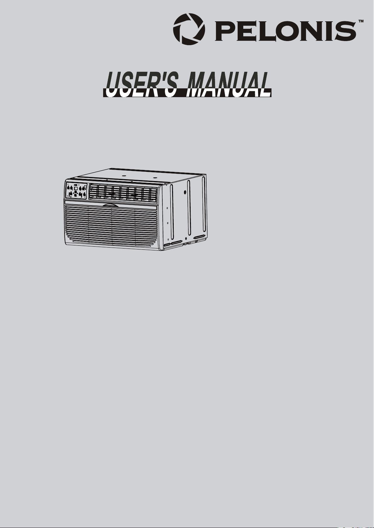
Before using your air conditioner, please read this manual carefully and keep it for future reference.
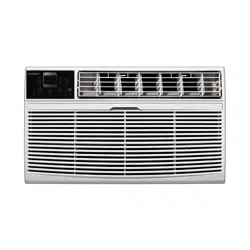
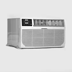
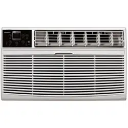
THROUGH THE WALL ROOM
AIR CONDITIONE R
Before usi ng your air conditioner, pleas e read
this manual c arefully and keep it for future reference.
WINDOW/WALL TYPE
ROOM AIR C ONDITIONER
-
Before usi ng your air conditioner, pleas e read
this manual c arefully and keep it for future reference.
WINDOW/WALL TYPE
ROOM AIR C ONDITIONER
-
Before usi ng your air conditioner, pleas e read
this manual c arefully and keep it for future reference.
WINDOW/WALL TYPE
ROOM AIR C ONDITIONER
-
Before usi ng your air conditioner, pleas e read
this manual c arefully and keep it for future reference.
WINDOW/WALL TYPE
ROOM AIR C ONDITIONER
-
Before usi ng your air conditioner, pleas e read
this manual c arefully and keep it for future reference.
WINDOW/WALL TYPE
ROOM AIR C ONDITIONER
-
Before usi ng your air conditioner, pleas e read
this manual c arefully and keep it for future reference.
WINDOW/WALL TYPE
ROOM AIR C ONDITIONER
-
Before usi ng your air conditioner, pleas e read
this manual c arefully and keep it for future reference.
WINDOW/WALL TYPE
ROOM AIR C ONDITIONER
-
Before usi ng your air conditioner, pleas e read
this manual c arefully and keep it for future reference.
WINDOW/WALL TYPE
ROOM AIR C ONDITIONER
-
Before usi ng your air conditioner, pleas e read
this manual c arefully and keep it for future reference.
WINDOW/WALL TYPE
ROOM AIR C ONDITIONER
-
Before usi ng your air conditioner, pleas e read
this manual c arefully and keep it for future reference.
WINDOW/WALL TYPE
ROOM AIR C ONDITIONER
-
Before usi ng your air conditioner, pleas e read
this manual c arefully and keep it for future reference.
WINDOW/WALL TYPE
ROOM AIR C ONDITIONER
-
Before usi ng your air conditioner, pleas e read
this manual c arefully and keep it for future reference.
WINDOW/WALL TYPE
ROOM AIR C ONDITIONER
-
TABLE OF CONTENTS
Installation Instructions
Normal Sounds................................................... 18
...................................... 4
Important Safety Instructions.......................... 1
Troubleshooting Tips
..................................
21
Air Conditioner Features
...................................
18
Care and Cleaning........................................ 20
MULTI-STEP SPEED ELECTRONIC CONTROL
PAT10R1ZWT
PAT10H2ZWT
PAT12R1ZWT
PAT12H2ZWT
PAT14R2ZWT
PAT14H2ZWT
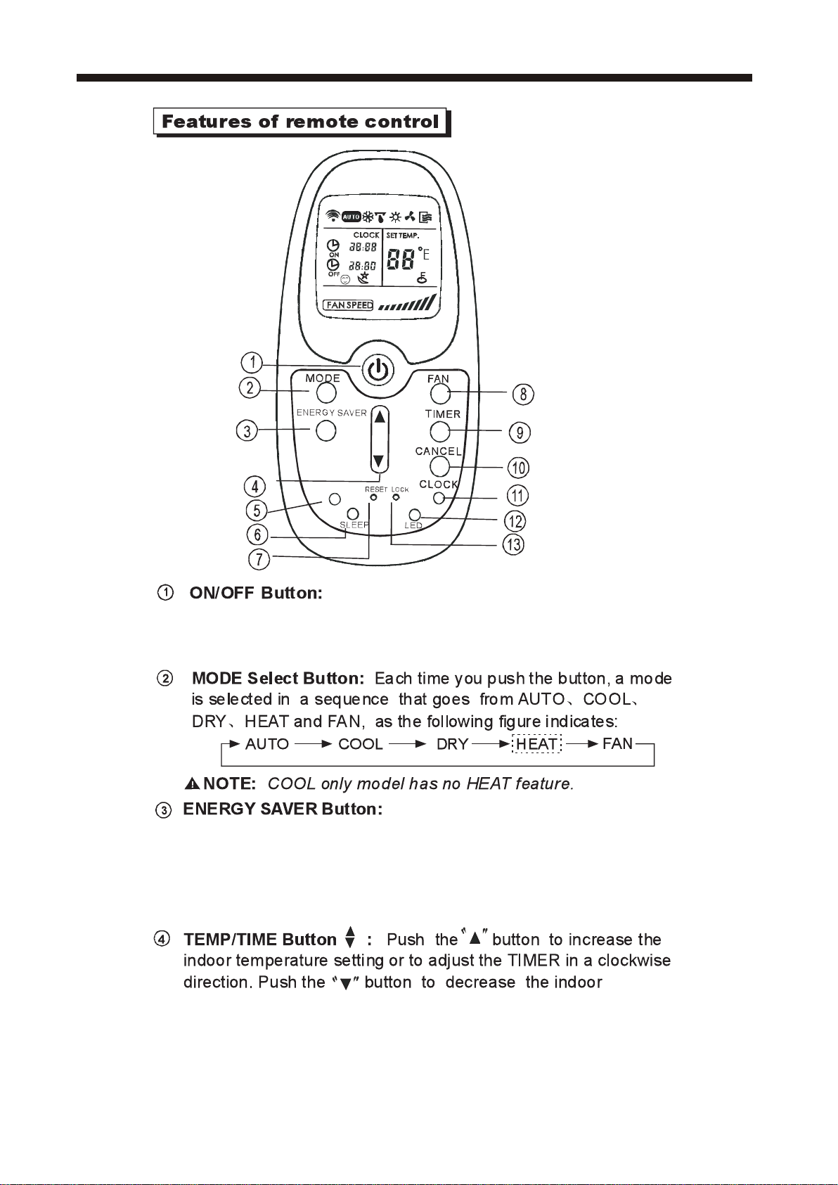
Features of remote control ......................... 23
Remote control operation instruction
..... 25
IMPORTANT SAFETY INSTRUCTIONS
Inside you will find many helpful hints on how to use and maintain your air conditioner
properly. Just a little preventive care on your part can save you a great deal of time
and money over the life of your air conditioner. You'll find many answers to common
problems in the chart of troubleshooting tips. If you review our chart of Troubleshooting
Tips first, you may not need to call for service at all.
To prevent injury to the user or other people and property damage, the following
instructions must be followed. Incorrect operation due to ignoring of instructions may
cause harm or damage. The seriousness is classified by the following indications.
This symbol indicates the possibility of death or serious injury.
Always do this.
Never do this.
CAUTION
This symbol indicates the possibility of injury or damage to property.
WARNING
WARNING
Plug in power plug
properly.
Do not modify power cord length or share the
outlet with other appliances.
Always ensure effective
grounding.
Unplug the unit if strange
sounds, smell, or smoke
comes from it.
Keep firearms away.
Ventilate room before operating air conditioner if there is
a gas leakage from another appliance.
Otherwise, it may cause electric
shock or fire due to excess heat
generation.
It may cause electric shock or fire due to heat generation.
Incorrect grounding may cause
electric shock.
It may cause fire and electric
shock.
It may cause fire.
It may cause explosion, fire and, burns.
It may cause electric shock or fire
due to heat generation.
It may cause electric shock.
It may cause failure of machine
or electric shock.
It may cause fire and electric
shock.
It may cause fire and electric
shock.
It may cause electric shock or fire.
If the power cord is damaged, it must be replaced by the
manufacturer or an authorised service centre or a similarly
qualified per son in order to avoid a hazard.
This could damage your health.
Incorrect installation may cause
fire and electric shock.
It may cause electric shock.
It may cause an explosion or fire.
It may cause failure and electric shock.
Do not operate or stop the
unit by inserting or pulling
out the power plug.
Do not operate with wet
hands or in damp
environment.
Do not allow water to run
into electric parts.
Do not use the socket if it is
loose or damaged.
Do not use the power cord
close to heating appliances.
Do not damage or use an unspecified power
cord.
Do not direct airflow at room occupants only.Always install circuit
breaker and a dedicated
power circuit.
Do not open the unit during operation.
Do not use the power cord near flammable gas
or combustibles, such as gasoline, benzene,
thinner, etc.
Do not disassemble or modify unit.
!!
!!
!!
!!
!!
!!
!!
!!
READ THIS MANUAL
1
When the air filter is to be
removed, do not touch the metal
parts of the unit.
It may cause an injury.
Do not clean unit when power is on
as it may c ause fi re an d el ectric sh ock,
it may cause an injury.
Operation with windows opened
may cause wetting of indoor and
soaking of household furniture.
When the unit is to be cleaned,
switch off, and turn off the circuit
breaker.
Use caution when unpacking and
installing. Sharp edges could cause injury.
Do not clean the air conditioner
with water.
Water may enter the unit and
degrade the insulation. It may
cause an electric shock.
This could injure the pet or plant.
It may cause electric shock and
damage.
Do not put a pet or house plant
where it will be exposed to direct
air flow.
Ventilate the room well when
used together with a stove, etc.
An oxygen shortage may occur.
Do not use this air conditioner to
preserve precision devices, food,
pets, plants, and art objects.It may
cause deterioration of quality, etc.
It may cause failure of product or
fire.
Do not use for special purposes.
If water enters the unit, turn the unit off at the power
outlet and switch off the circuit breaker. Isolate
supply by taking the power-plug out and contact a
qualified service technician.
!!
!!
!!
!!
It may cause failure of appliance
or accident.
Appearance may be deteriorated
due to change of product color or
scratching of its surface.
If bracket is damaged, there is
concern of damage due to falling
of unit.
There is danger of fire or electric
shock.
Operation without filters maycause
failure.
It contains contaminants and
could make you sick.
Stop operation and close the
window in storm or hurricane.
!!
Do not use strong detergent
such as wax or thinner but use
a soft cloth.
Ensure that the installation bracket of the
outdoor appliance is not damaged due
to prolonged exposure.
Hold the plug by the head of the
power plug when taking it out.
!!
Turn off the main power
switch when not using the
unit for a long time.
!!
!!
!!
Always insert the filters securely.
Clean filter once every t wo w eeks.
!!
Do not place heavy object on the power
cord and ensure that the cord is not
compressed.
Do not drink water drained
from air conditioner.
This appliance is not intended for use by persons
(including children) with reduced physical ,sensory
or mental capabilities or lack of experience and
knowledge, unless t hey h aveb eengi vensu pervision
or instruction concerning use of the appliance by
a person responsible for their safety.
Children should be supervised to ensure that they
do not play with the appliance.
If the supply cord is damaged, it must be replaced
by the manufacturer, its service agent or similarly
qualified persons in order to avoid a hazard.
CAUTION
2
CAUTION
Do not place obstacles around
air-inlets or inside of air-outlet.
The appliance shall be installed in accordance
with national wiring regulations.
Do not operate your air conditioner in a wet room
such as a bathroom or laundry room.
The appliance with electric heater shall have at
l east 1 m eter s pace to th eco mbustible materials.
Contact the authorised service technician for
repair or maintenance of this unit.
Contact the authorised installer for installation
of this unit.
IMPORTANT SAFETY INSTRUCTIONS
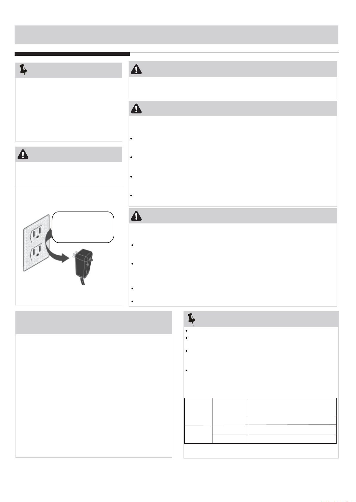
Do not, under any
circumstances, cut,
remove, or bypass
the grounding prong.
Power supply cord
with 3-prong grounding plug
and current detection device
Grounding type wall
receptacle
WARNING
NOTE:
The power supply cord with this air
conditioner contains a current detection
device designed to reduce the risk of fire.
Please refer to the section Operation
of Current Device for details.In the event
that the power supply cord is damaged,
it cannot be repaired-it must be replaced
with ac ordf romt heP roductM anufacturer.
Avoid fire hazard or electric shock. Do not
use an extension cord or an adaptor plug.
Do not remove any prong from the power
cord.
WARNING
For Your Safety
WARNING
Prevent Accidents
WARNING
Electrical Information
Do not store or use gasoline or other flammable vapors and liquids in the vicinity
of this or any other appliance.
Operation of Current Device
(Applicable to the unit adopts current detection
device only )
The power supply cord contains a current device that senses
damage to the power cord. To test your power supply cord do
the following:
1. Plug in the Air Conditioner.
2. The power supply cord will have TWO buttons on the plug
he
ad. Press the TEST button, you will notice a click as the
RESET button pops out.
3. Press the RESET button, again you will notice a click as
the
button engages.
4. The power supply cord is now supplying electricity to the
un
it. (On some products this it also indicated by a light on
the
plug head.)
3
To reduce the risk of fire, electrical shock, or injury to persons when using your
air conditioner, follow basic precautions, including the following:
Be sure the electrical service is adequate for the model you have chosen. This
information can be found on the serial plate, which is located on the side of the
the cabinet and behind the grille.
If the air conditioneri s t o b e in stalled in a w indow, yo u w ill pr obably w ant to cl ean
both sides of the g lass f irst.I f th e w indowis a tri ple-track ty pe w ith a sc reen pa nel
included, remove the screen completely before installation.
Be sure the air c onditionerh as b een s ecurely a nd c orrectly in stalled a ccording to
the installation instructions in this manual. Save this manual for possible future
use in removing or installing this unit.
When handling the air conditioner, be careful to avoid cuts f rom s harp m etal f ins
on front and rear coils.
The complete electical rating of your new room air conditioner is stated on the
serial plate. Refer to the rating when checking the electrical requirements.
Be sure the air conditioner is properly grounded. To minimize shock and fire
hazards, proper grounding is important. The power cord is equipped with a
three-prong grounding plug for protection against shock hazards.
Your air conditioner must be used in a properly grounded wall receptacle. If the
wall receptacle you intend to use is not adequately grounded or protected by a
time delay fuse or circuit breaker, have a qualified electrician install the proper
receptacle. Ensure the receptacle is accessible after the unit installation.
Do not run air conditioner without side protective cover in place.This could
result in mechanical damage within the air conditioner.
Do not use an extension cord or an adapter plug.
IMPORTANT SAFETY INSTRUCTIONS
Do not use this device to turn the unit on or off.
Always make sure the RESET button is pushed in for
correct operation.
The power supply must be replaced if it fails reset when
either the TEST button is pushed, or it cannot be reset. A
new one can be obtained from the product manufacturer.
If power supply cord is damaged, it cannot be repaired. It
MUST be replaced by one obtained from the product
manufacturer.
NOTE:
NOTE:This air conditioner is designed to be operated
under condition as follows:
Cooling
operation
Outdoor temp:
Indoor temp:
Heating
operation
Outdoor temp:
O
O
23-76 F/-5-24 C
Indoor temp:
O
O
32-80 F/0-27 C
OO OO
64-109 F/18-43 C (64-125 F/18-52
C
for special tropical models)
O
O
62-90 F/17-32 C
Note: Performance may be reduced outside of these
operating temperatures.
1
/
2
1
/
2
1
/
2
1
/
2
1
/
2
1
/
2
1
/
2
1
/
2
4
INSTALLATION INSTRUCTIONS
Read these instructions completely
and carefully.
IMPORTANT- Save these
instructions for local inspector s use.
IMPORTANT- Observe all
governing codes and ordianaces.
Note to Consumer- Keep these
instructions for futrue reference.
Note to Installer- Be sure to leave these
instructions with the Consumer.
Completion time- Approximately 1 hour.
Skill level- Installatio of this appliance
requires basic mechanical skills.
We recommend that two people install
this product.
Proper installation is the responsibility
of the installer.
Product failure due to improper installation
is not covered under the Warranty.
You MUST use all supplied parts and use
proper installation procedures as described
in these instructions when installing this air
conditioner.
BEFORE YOU BEGIN
Do not, under any circumstances, cut or remove the
third (ground) prong from the power cord.
CAUTION
Do not change the plug on the power cord of the air
conditioner.
Aluminum house wiring may present special
problems- consult a qualified electircian.
When handling unit, be careful to avoid cuts from sharp
metal edges and aluminum fins on front and rear coils.
Save Carton and these Installation Instructions for future
reference. The carton is the best way to store unit during
winter, or when not in use.
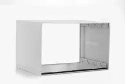
NOTE:
Note that the air conditioner dimensions are: 24 inches
wide, 14 inches high, and 18 inches deep(without front).
Install Air Conditioner according to these installation
instructions to achieve the best performance. Save
these installation instructions for future reference.
NOTE: Do not use any screws other than those
specified here.
Do This First (for existing sleeve)
Items in Kit
You may not need all parts in the kit. Discard unused
parts.
Name
Spec.
Qty
Tapered Spacer Blocks
17 Long
2
Centering/Support Blocks
4 x3 x1
4
Plastic Divider
1/8 x4 x14
2
Stuffer Seal
1 x1 x84
1
Seal 1 x1 x25
1 x1 x14
1 x3/8 x25
Seal
Seal
Seal
1 x3/8 x14
1 x3/4 x14
Seal
3
3
2
2
2
Trim Frame(side legs)
Trim Frame(top & bottom legs)
Ground Wire(green)
Toothed Washer for grounding
screw
Grounding Screw
Grille(plastic)
Grille Aluminum
Nuts(plastic)
Screw Washer
Screw
2
2
1
2
1
1
1
4
4
4
5
How to Install
1. Identify the wall-sleeve brand for your installation, from the chart below.
Wall Sleeve Dimensions
(inches)
Width
Height Depth
Brand
Pelonis
White-Westinghouse
Frigidaire
Carrier(52F Series)
General Electric/Hotpoint
Whirlpool
Fedders/Emerson
Sears/Kenmore
Carrier(51S Series)
Emerson/Fedders
Friedrich
1
/
2
25 15 16,17 or 22
1
/
2
1
/
4
26 15 15
7
/
8
5
/
8
7
/
8
25 16 17 or 23
1
/
8
1
/
2
3
/
4
27 16 16 or 19
3
/
4
3
/
4
3
/
4
25 16 18
5
/
8
7
/
8
3
/
4
26 15 15
3
/
4
/
27 16 16
3
4
3
/
4
NOTE: All wall sleeves used to mount the new Air Conditioner must be in sound structural condition
and have a rear grille that securely attaches to sleeve, or rear flange that serves as a stop for the Air
Conditioner.
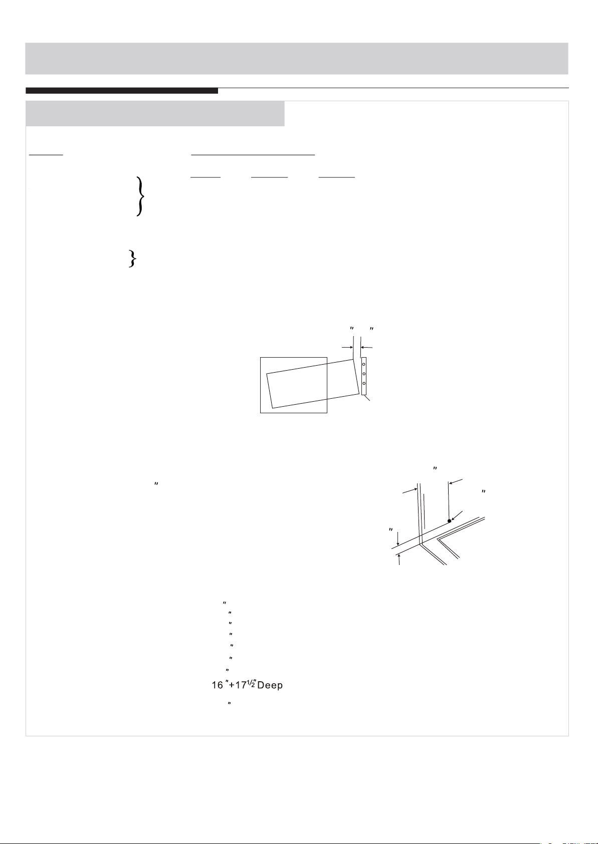
CAUTION: When installation is complete,
replacement unit MUST have a rearward
slope as shown.
REAR
LEVEL
FRONT
UNIT
Wall
Sleeve
1
/
4 to
5
/
16
2. Remove old Air Conditioner from wall sleeve and prepare wall sleeve as follows:
--- Clean interior (do not disturb seals).
--- Wall sleeve must be securely fastened in wall before installing Air Conditioner.
Drive more nails or screws through sleeve, into wall, if needed.
--- Repair paint if needed.
3. If not existing, drill a 1/8 clearance hole for
grounding screw through left side of wall sleeve,
in a clear area about 3 inches maximum back from
front edge of sleeve, using grounding screw and
toothed washer. Pull loose end of ground wire out
front of sleeve, and temporarily bend it down and
around lower edge of sleeve.This ground wire will
later be attached to frame of air conditioner once
it is installed.
Wall sleeve to unit
sleeve grounding
1
3
Max.
1/8
Hole
4. Prepare the wall sleeve for installation of the new unit per the following Brand instructions.
#1 Emerson 15 Deep
#2 Fedders 19 Deep
#3 Fedders or Friedrich 16 Deep
#4 General Electric/Hotpoint 16 Deep
#5 Sears or Carrier(51S Series) 18 Deep
#6 Whirlpool 17 Deep
#7 Whirlpool 23 Deep
Frigidaire/Carrier(52F Series)
#9 White-Westinghouse/Frigidaire 22 Deep
3
/
4
/
4
7
/
8
/
3
/
4
/
4
5
/
8
/
1
/
8
/
#
8 Pelonis/White-Westinghouse/
5. Identify your wall sleeve type and follow the instructions for that type in the following pages.
INSTALLATION INSTRUCTIONS
6
T
his units increased performance characteristics result from having two rear air intakes.
It is very important that these installation instructions are followed so your unit can operate at maximum
efficiency.
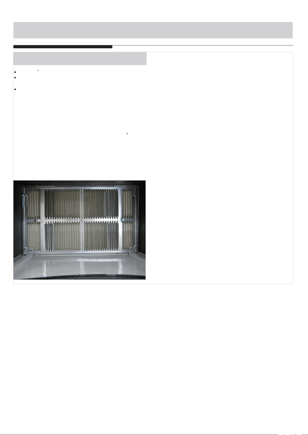
If this is an existing sleeve, and there is an existing rear grille, it needs to be replaced by one that has
been shipped with the unit in the accessory kit.
FOR INCREASED EFFICIENCY,UTILIZE THE PROVIDED LOUVERED REAR PANEL Installation of
new grille provided with unit
1. Remove the existing grille.
2. Place the grille included with the new air conditioner towards the rear of the sleeve.
3. Mark through the hole positions.
4. Drill through the sleeves flanges with a 1/8 drill bit.
5. Attached the new grille with self-threading screws and washers.
6. It is VERY IMPORTANT that the grille is placed exactly as shown below.
7. Most decorative exterior grilles may be left in place as long as the proper interior air direction grille
is installed.
INSTALLATION INSTRUCTIONS
IMPORTANT
7
INSTALLATION INSTRUCTIONS
Wall Sleeve Brands:
#1 Emerson 15 Deep
1. Remove existing rear
grille as shown on Page
6 of this manual and replace with provided
louvered rear panel. Install as shown here.
NOTE: You may need to drill holes in flange of
existing sleeve to match new rear grille.
2. Attach(1)1 x3/8 x25 long seal in the center at
the top of the sleeve. Remove the backing paper
and press into position.
3. Attach the (2) 1 x3/8 x14 long seals to the
left and right sides of the sleeve.
4. Cut (2) 1 x3/8 x25 long seals to 14 long,and
attach it to the vertical sections of the rear grille
as shown.
5. Attach (2)4 x3 x1 centering/support blocks
one on each side wall. Place in center of side
wall with the tapered end facing the opening.
6. Gently slide unit into sleeve.
7. Before sliding all-the-way back, remove 2nd
screw from front on left side of unit.
8. Remove the plastic washer from the screw.
9. Screw and attach the other end of the ground
wire to the unit as shown in picture. Make sure
that the toothed washer is against the cabinet.
10.Slide the unit completely to the rear to ensure
a good seal, making sure the ground wire does
not become tangled.
11.Seal & Frame the unit as described on page 17.
12. If you have difficulty with mounting the grill to
the sleeve, follow the instructions for direct
mounting on Page 16.
1
/
2
1
/
2
1
/
2
22
44 44
4
4
3
8
3
8
INSTALLATION INSTRUCTIONS
Wall Sleeve Brands:
#2 Fedders 19 Deep
1.
3
4
/
2. Attach(2)4 x3 x1 centering/support blocks
one on each side wall. Place in center of side
wall with the tapered end facing the opening.
3. Cut (2) 17 Tapered Spacer Blocks as shown
below into two pieces.
4. The 4 section is placed in front of the rib on
base with the tapered end facing the back of
the sleeve. The remaining portion will be
placed behind the rib again sloping toward
the rear of the sleeve. This helps induce a
rearward slope on the unit.
5. Attach (1)1 x3/8 x25 long seal in the center
at the top of the sleeve. Remove the backing
paper and press into position.
6. Attach (2) 1 x3/8 x14 seals to the left and
right sides of the sleeve.
7. Cut (2) 1 x3/8 x25 long seals to 14 long
and attach it to the vertical sections of the rear
grille as shown.
8. Gently slide unit into sleeve.
9. Before sliding all-the-way back, remove 2nd
screw from front on left side of unit.
10. Remove the plastic washer from the screw.
11. Screw and attach the other end of the ground
wire to the unit as shown in picture. Make sure
that the toothed washer is against the cabinet.
12.
Slide the unit completely to the rear to ensure
a good seal, making sure the ground wire does
not become tangled.
13.
Seal & Frame the unit as described on page 17.
14. If you have difficulty with mounting the grill to
the sleeve, follow the instructions for direct
mounting on Page 16.
1
/
2
1
/
2
/
2
1
/
2
/
2
Cut Here
3
/
4
17
Tapered Spacer Block
1
Protection Paper
Backing
55
4
Remove existing rear grille as shown on Page
6 of this manual and replace with provided
louvered rear panel. Install as shown here.
NOTE: You may need to drill holes in flange
of existing sleeve to match new rear grille.
44
44
4
4
3
8
3
8
8
INSTALLATION INSTRUCTIONS
Wall Sleeve Brands:
#3 Fedders or Friedrich 16 Deep
1.Remove existing rear grille as shown on Page
6 of this manual and replace with provided
louvered rear panel. Install as shown here.
NOTE: You may need to drill holes in flange of
existing sleeve to match new rear grille.
3
4
/
2. Attach(2)4 x3 x1 centering/support blocks
one on each side wall. Place in center of side
wall with the tapered end facing the opening.
3. Cut (2) 17 Tapered Spacer Blocks as shown
below into three pieces.
4. The 2 section is placed in front of the rib on
base with the tapered end facing the back of
the sleeve. Cut the remaining portion to 12
and placed behind the rib again sloping toward
the rear of the sleeve. This helps induce a
rearward slope on the unit.
5. Attach (1)1 x3/8 x25 long seal in the center
at the top of the sleeve. Remove the backing
paper and press into position.
6. Attach (2) 1 x3/8 x14 seals to the left and
right sides of the sleeve.
7. Cut (2) 1 x3/8 x25 long seals to 14 long
and attach it to the vertical sections of the rear
grille as shown.
8. Gently slide unit into sleeve.
9. Before sliding all-the-way
back, remove 2nd
screw from front on left side of unit.
10. Remove the plastic washer from the screw.
11. Screw and attach the other end of the ground
wire to the unit as shown in picture. Make sure
that the toothed washer is against the cabinet.
12.Slide the unit completely to the rear to ensure
a good seal, making sure the ground wire does
not become tangled.
13.Seal & Frame the unit as described on page 17.
14. If you have difficulty with mounting the grill to
the sleeve, follow the instructions for direct
mounting on Page 16.
1
/
2
1
/
2
/
2
1
/
2
/
2
Cut Here
3
/
4
17
Tapered Spacer Block
1
Protection Paper
Backing
12-1/2
2-1/2
1
/
2
1
/
2
5
4 4
4
4
3
8
3
8
9
INSTALLATION INSTRUCTIONS
Wall Sleeve Brands:
1. Remove existing rear grille as shown on Page
6 of this manual and replace with provided
louvered rear panel. Install as shown here.
NOTE: You may need to drill holes in flange of
existing sleeve to match new rear grille.
#4 General Electric/Hotpoint 16
7
/
8
Deep
2. Cut (2) 17 Tapered Spacer Blocks as shown
below into two pieces.
3. Install 13 section as shown with the tapered end
from the back of the sleeve. This helps induce a
rearward slop on the unit.
4. Attach (1)1 x3/8 x25 long seal in the center
at the top of the sleeve. Remove the backing
paper and press into position.
5. Attach (2) 1 x3/8 x14 seals to the left and
right sides of the sleeve.
6. Cut (2) 1 x3/8 x25 long seals to 14 long
and attach it to the vertical sections of the rear
grille as shown.
7. Center unit and gently slide unit into sleeve.
8. Before sliding all-the-way back, remove 2nd
screw from front on left side of unit.
9. Remove the plastic washer from the screw.
10. Screw and attach the other end of the ground
wire to the unit as shown in picture. Make sure
that
the
toothed washer is against the cabinet.
11.Slide the unit completely to the rear to ensure
a good seal, making sure the ground wire does
not become tangled.
12.Seal & Frame the unit as described on page 17.
13. If you have difficulty with mounting the grill to
the sleeve, follow the instructions for direct
mounting on Page 16.
1
/
2
3
/
4
17
Tapered Spacer Block
1
Protection Paper
Backing
Cut Here
13
5
4
4
4
4
4
3
8
3
8
10
INSTALLATION INSTRUCTIONS
Wall Sleeve Brands:
#5 Sears or Carrier 51S Series
( 18 Deep)
1. Remove existing rear grille as shown on Page
6 of this manual and replace with provided
louvered rear panel. Install as shown here.
NOTE: You may need to drill holes in flange of
existing sleeve to match new rear grille.
5
8
/
2. Install (2) tapered spacer blocks to the floor of
the sleeve as shown. This helps induce a
rearward slop on the unit.
3. Install as shown with the tapered end from
the back of the sleeve. This helps induce a
rearward slop on the unit.
4. Attach (1)1 x3/8 x25 long seal in the center
at the top of the sleeve. Remove the backing
paper and press into position.
5. Attach (2) 1 x3/8 x14 seals to the left and
right sides of the sleeve.
6. Cut (2) 1 x3/8 x25 long seals to 14 long
and attach it to the vertical sections of the rear
grille as shown.
7. Center unit and gently slide unit into sleeve.
8. Before sliding all-the-way back, remove 2nd
screw from front on left side of unit.
9. Remove the plastic washer from the screw.
10. Screw and attach the other end of the ground
wire to the unit as shown in picture. Make sure
that the toothed washer
is against
the cabinet.
11.Slide the unit completely to the rear to ensure
a good seal, making sure the ground wire does
not become tangled.
12.Seal & Frame the unit as described on page 17.
13. If you have difficulty with mounting the grill to
the sleeve, follow the instructions for direct
mounting on Page 16.
1
/
2
5
4
4
4
4
4
3
8
3
8
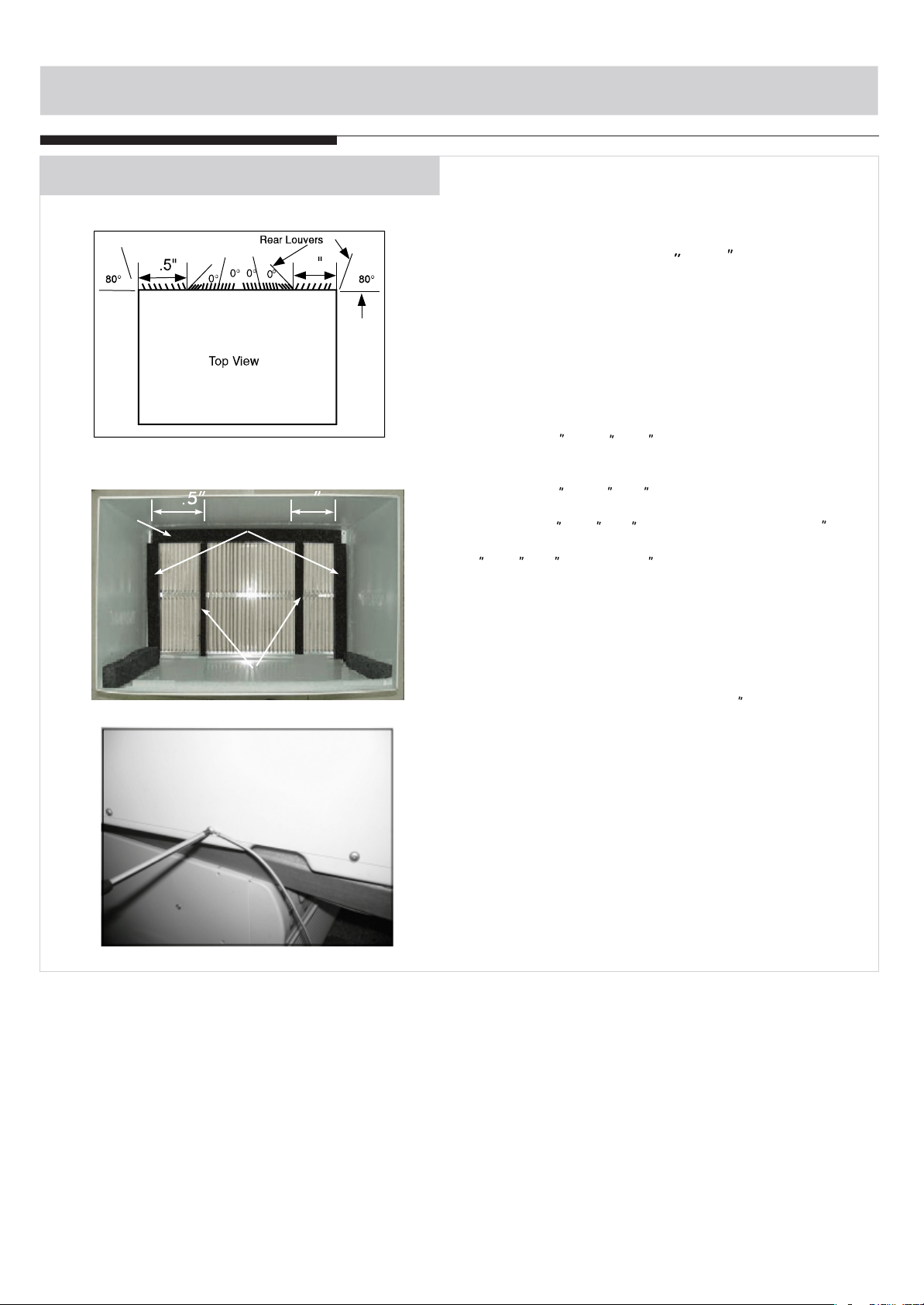
11
INSTALLATION INSTRUCTIONS
Wall Sleeve Brands:
#6 Whirlpool 17 Deep
1. Remove existing rear grille as shown on Page
6 of this manual and replace with provided
louvered rear panel. Install as shown here.
NOTE: You may need to drill holes in flange of
existing sleeve to match new rear grille.
1
8
/
2. Cut (2) 17 Tapered Spacer Blocks as shown
below into two pieces.
3. I
nstall 13 section to the floor of the sleeve as
shown. This helps induce a rearward slop on the
unit.
4. Attach (1)1 x3/8 x25 long seal in the center at
the top of the sleeve. Remove the backing paper
and press into position.
5. Attach (2) 1 x3/8 x14 seals to the left and
right sides of the sleeve.
6. Cut (2) 1 x3/8 x25 long seals to 14 long
and attach it to the vertical sections of the rear
grille as shown.
7. Center unit and gently slide unit into sleeve.
3
/
4
17
Tapered Spacer Block
1
Protection Paper
Backing
Cut Here
13
55
44
44
44
4
4
3
8
3
8
12
8. Before sliding all-the-way back, remove 2nd
s
crew from front on left side of unit.
9. Remove the plastic washer from the screw.
10. Screw and attach the other end of the ground
wire to the unit as shown in picture. Make sure
that the toothed washer is against the cabinet.
10. Slide the unit completely to the rear to
ensure a good seal, making sure the ground wire
does not become tangled.
12. Seal & Frame the unit as described on page
17.
13. If you have difficulty with mounting the grill to
the sleeve, follow the instructions for direct
mounting on Page 16.
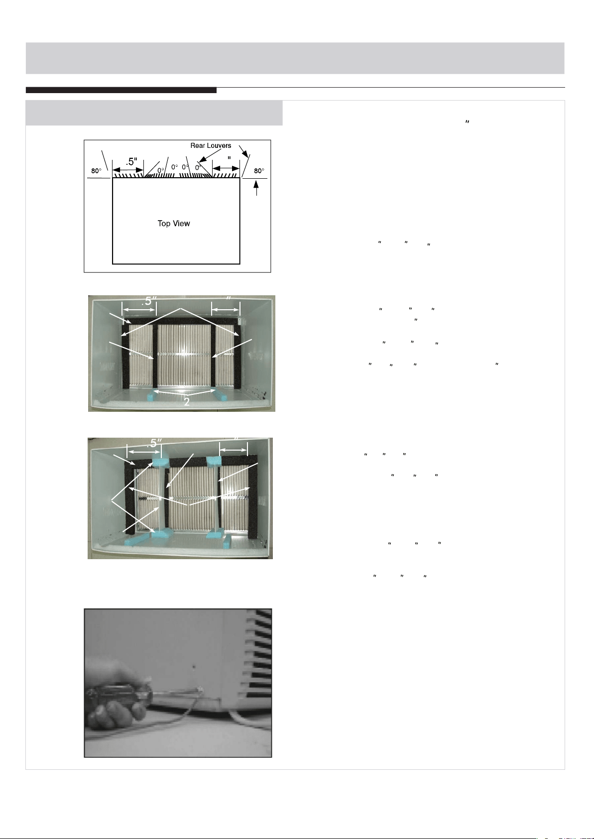
INSTALLATION INSTRUCTIONS
Wall Sleeve Brands:
#7 Whirlpool ( 23 Deep)
1. Remove existing rear grille as shown on Page
6 of this manual and replace with provided
louvered rear panel. Install as shown here.
NOTE: You may need to drill holes in flange of
existing sleeve to match new rear grille.
2. Place (2) 1 x1 x14 seals against each side.
3. Gently slide unit in and check if amount extend-
ing from the sleeve is sufficient once the trim
frame is attached.
4. If position is Ok, remove unit and proceed to
the next step. If not go to step 9.
5. Attach (1)1 x1 x25 long seal in the center
at the top of the sleeve. Remove the backing
paper and press into position.
6. Attach (2) 1 x1 x14 seals to the left and
right sides of the sleeve.
7. Cut (2) 1 x x25 long seals to 14 long
and attach to the vertical sections of the grille as
shown.
8. Attach the tapered spacer blocks to the floor of
the sleeve. Now go to step 15.
Use these next steps if the unit requires extra
extension into the room.
9. Attach 1 x x14 long seal over the solid
vertical portion of the rear grille.
10. Attach (4) 4 x3 x1 foam blocks with the
slot overlapping the seal above.
11. Install the divider into the slots of the foam
blocks. You may need to trim the length to size.
12. Repeat steps 9-11 for the other vertical shown
portion of the grille as shown in the picture.
13. Attach (2) 1 x1 x14 seals along the sides
of the sleeve again making sure all seals are
flush.
14.Cut the 1 x1 x25 seal to fit the top of the
sleeve. The pieces must be fitted flush to the
edge of the divider.
15. Center unit and gently slide unit into sleeve.
16. Before sliding all-the-way back, remove 1st
screw from front on left side of unit.
17. Remove the plastic washer from the screw.
18. Screw and attach the other end of the ground
wire to the unit as shown in picture. Make sure
that the toothed washer is against the cabinet.
19.Slide the unit completely to the rear to ensure
a good seal, making sure the ground wire does
not become tangled.
20.Seal & Frame the unit as described on page 17.
21. If you have difficulty with mounting the grill to
the sleeve, follow the instructions for direct
mounting on Page 16.
Because of the increased unit depth, first try
dry fitting using the method described below:
1
/
2
1
/
2
1
/
2
3
/
8
3
/
4
1
/
2
1
/
2
1
/
2
1
/
2
66
55
1212
9 9
1111
1313
1010
1414
1
/
2
77
44
44
4
4
3
8
3
8
44
44
77
13
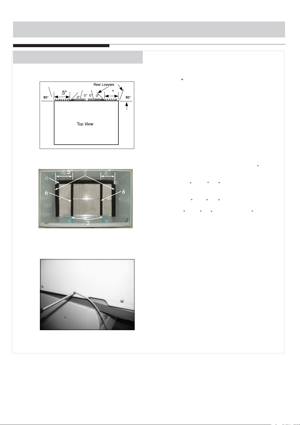
INSTALLATION INSTRUCTIONS
Wall Sleeve Brands:
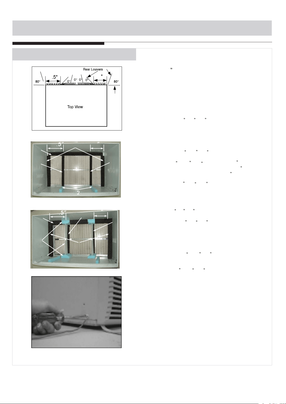
#8 Pelonis/White Westinghouse/Frigidaire
Carrier 52F Series ( 16 +17 Deep)
1.Remove existing rear grille as shown on Page
6 of this manual and replace with provided
louvered rear panel. Install as shown here.
NOTE: You may need to drill holes in flange of
existing sleeve to match new rear grille.
2.
Attach (1)1 x3/8 x25 long seal in the center
at the top of the sleeve. Remove the backing
paper and press into position.
3. Attach (2) 1 x3/8 x14 seals to the left and
right sides of the sleeve.
4. Attach (2) 1 x3/4 x14 long seals vertically 4.5
from the left side of the sleeve .Attach the other
1 x3/4 x14 long seal 4 from the right side of the
sleeve.
5. Center unit and gently slide unit into sleeve.
6. Before sliding all-the-way back, remove 2nd
screw from front on left side of unit.
7. Remove the plastic washer from the screw.
8. Screw and attach the other end of the ground
wire to the unit as shown in picture. Make sure
that the toothed washer is against the cabinet.
9. Slide the unit completely to the rear to ensure
a good seal, making sure the ground wire does
not become tangled.
10.Seal & Frame the unit as described on page 17.
11. If you have difficulty with mounting the grill to
the sleeve, follow the instructions for direct
mounting on Page 16.
1
/
2
44
22
33
44
44
4
4
3
8
3
8
14
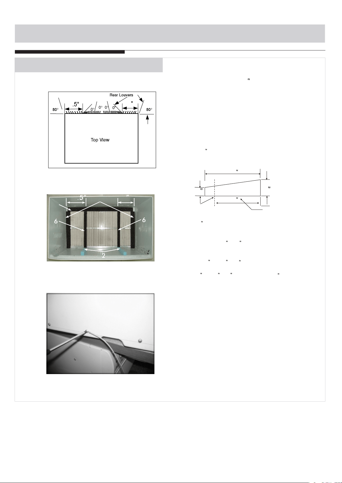
INSTALLATION INSTRUCTIONS
Wall Sleeve Brands:
#9 White Westinghouse or Frigidaire
( 22 Deep)
2. Place (2) 1 x1 x14 seals against each side.
3. Gently slide unit in and check if amount extend-
ing from the sleeve is sufficient once the trim
frame is attached.
4. If position is Ok, remove unit and proceed to
the next step. If not go to step 8.
5. Attach (1)1 x1 x15 long seal to the left and
right sides of the sleeve.
6. Cut (1) 1 x1 x25 long seal to 14 long and
attach it vertically to the rear grill 4.5 from
the left side ,repeat and attach 4 from the right
side.
7. Attach(1) 1 x1 x25 long seal in the center at
the top of the sleeve.Remove the backing paper
and press into position.Proceed to step 14.
Use these next steps if the unit requires extra
extension into the room.
8. Attach 1 x x14 long seal over the solid
vertical portion of the rear grille.
9. Attach (4) 4 x3 x1 foam blocks with the
slot overlapping the seal above.
10. Install the divider into the slots of the foam
blocks. You may need to trim the length to size.
11. Repeat steps 8-10 for the other vertical shown
portion of the grille as shown in the picture.
12. Attach (2) 1 x1 x14 seals along the sides
of the sleeve again making sure all seals are
flush.
13.Cut the 1 x1 x25 seal to fit the top of the
sleeve. The pieces must be fitted flush to the
edge of the divider.
14. Center unit and gently slide unit into sleeve.
15. Before sliding all-the-way back, remove 1st
screw from front on left side of unit.
16. Remove the plastic washer from the screw.
17. Screw and attach the other end of the ground
wire to the unit as shown in picture. Make sure
that the toothed washer is against the cabinet.
18.Slide the unit completely to the rear to ensure
a good seal, making sure the ground wire does
not become tangled.
19.
Seal & Frame the unit as described on page 17.
20. If you have difficulty with mounting
the grill to
the sleeve, follow the instructions for direct
mounting on Page 16.
Because of the increased unit depth, first try
dry fitting using the method described below:
1
/
2
1
/
2
1
/
2
1
/
2
3
/
4
1
/
2
1
/
2
1
/
2
1
/
2
1
/
2
1.
66
77
1111
88
1010
1212
99
1313
Remove existing rear grille as shown on Page
6 of this manual and replace with provided
louvered rear panel. Install as shown here.
NOTE: You may need to drill holes in flange
of existing sleeve to match new rear grille.
55
66
44
44
4
4
3
8
3
8
44
44
15
INSTALLATION INSTRUCTIONS
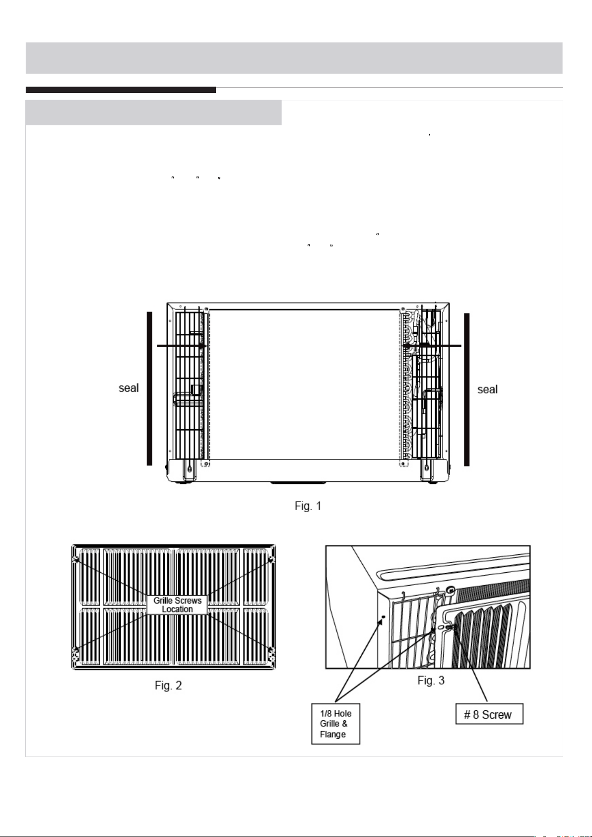
Direct Unit Mounting:
The previous directions are the preferable way to mount the new rear grill. The units performance is
slightly better and the possibility of draughts is reduced. As a last resort, direct mounting of the grille
to the unit can be considered.
Note: The grille must be installed prior to inserting the unit into the sleeve.
1. Attach the 2 seal pieces (1 X3/8 X14 ) as shown in Fig. 1.
2.Position the grille over the rear of the unit making sure that:
a. The double set of screw holes are at the bottom.
b. The fins of the grill are pointed away from the unit.
3. Align the top of the grille with the top of the unit. The overhang on each side is equal.
4. If the unit has not been pre-drilled (some models), carefully drill 4-1/8 holes through the
grille and into the side flange of the unit approximately 1 to 2 from the top and bottom as
in Fig. 2, 3 .
(Be careful not to drill into the copper heat exchanger coils.)
5. Install 4 - #8 self tapping screws to affix the grille to the unit.
6. Insert the unit into the sleeve.
1
/
2
16
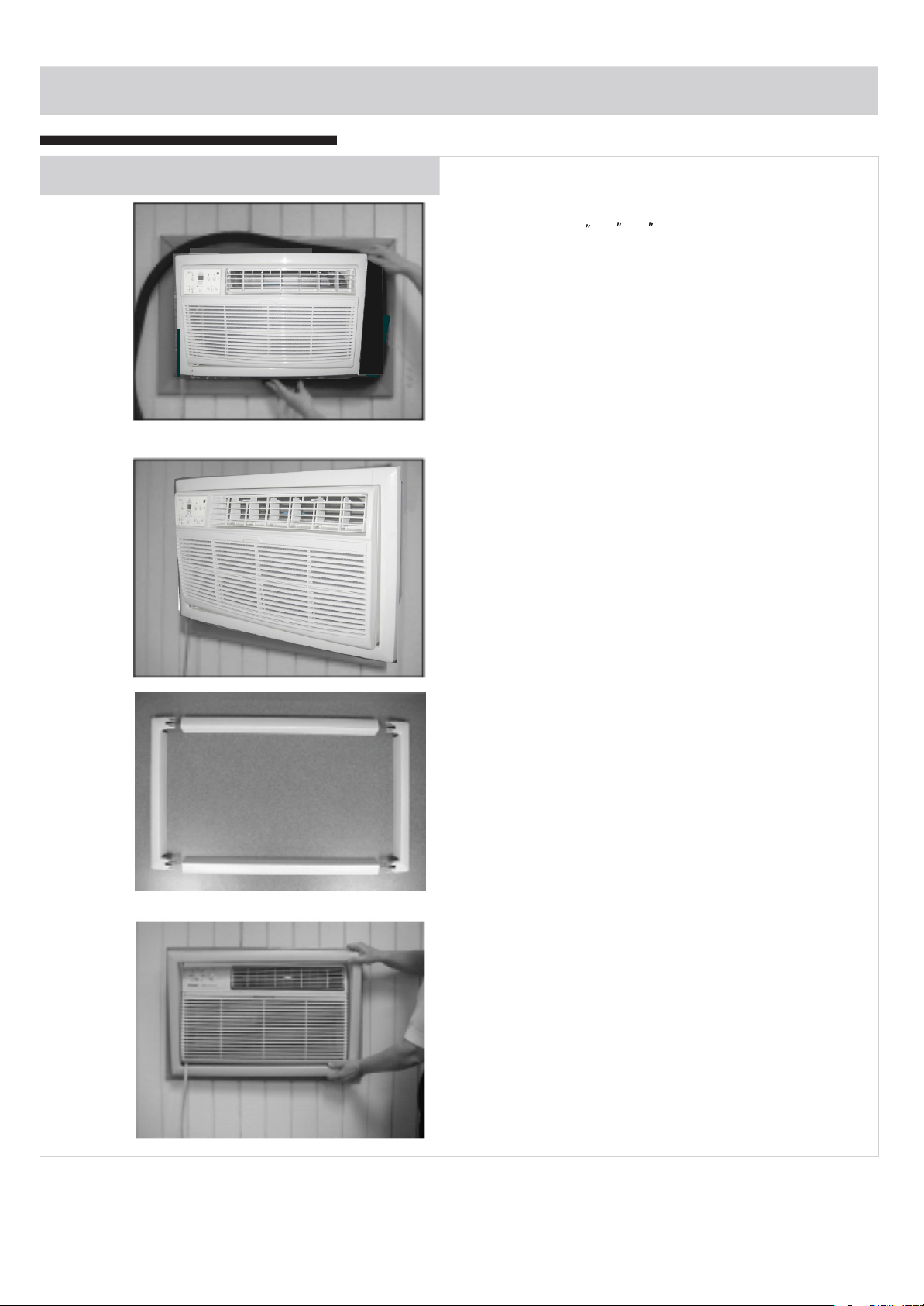
1. Install the 1 x1 x84 long stuffer-seal between
the wall-sleeve and the unit. A flat-bladed
screwdriver or putty knife is recommended.
1
/
2
2. Assemble the trim frame by inserting top and
bottom pieces into side pieces and snapping
into place.
3. Pull cord through trim frame then slide over
unit until flush with wall.
INSTALLATION INSTRUCTIONS
FINISHING INSTALLATION:
17
NORMAL SOUNDS
All the illustrations in this manual are for explanation purpose only. Your air
conditioner may be slightly different.
NOTE:
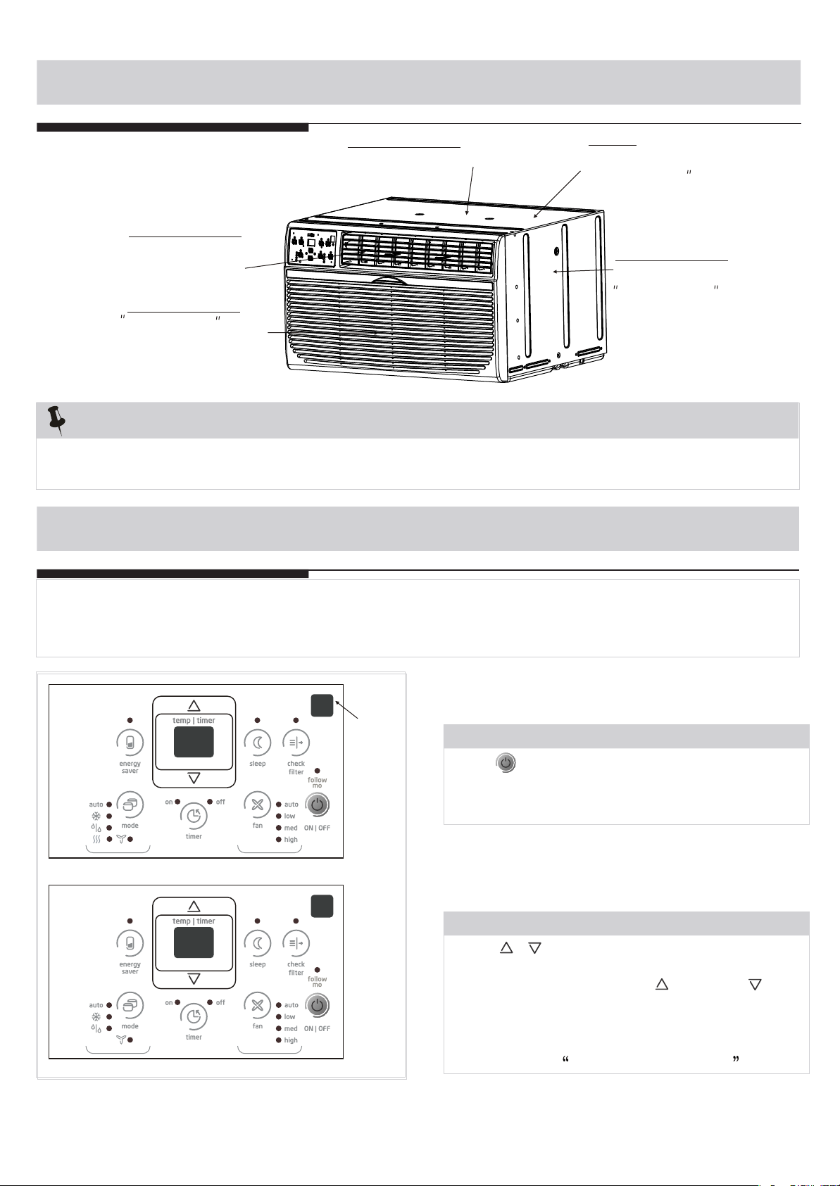
AIR CONDITIONER FEATURES
Before you begin, thoroughly familiarize yourself with the control panel as shown below and all its
functions, then follow the symbol for the functions you desire. The unit can be controlled by the unit
control alone or with the remote.
ELECTRONIC CONTROL OPERATING INSTRUCTIONS
Sound of Rushing Air
At the front of the unit, you may
hear the sound of rushing air
being moved by the fan
High Pitched Chatter
High efficiency compressors
may have a high pitched chatter
during the cooling cycle.
Gurgle/Hiss
Gurgling or hissing noise may
be heard due to refrigerant
passing through evaporator
during normal operation.
Pinging or Switching
Droplets of water hitting condenser
during normal operation may cause
pinging or switching sounds.
Vibration
Unit may vibrate and make noise
because of poor wall or window
construction or incorrect installation.
18
(Cooling Only Models)
(Electric Heating Models)
RECEPTOR
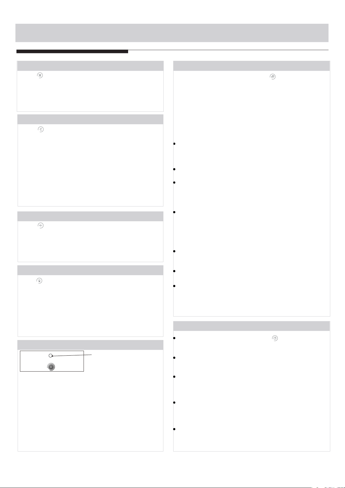
TO TURN UNIT ON OR OFF:
Press ON/OFF button to t urn unit on or off.
NOTE: The Energy Saver function will automatically
initiate under the Cool, Dry, Auto (only Auto-Cooling
and Auto-Fan) modes.”
TO CHANGE TEMPERATURE SETTING:
Press / UP/DOWN button to change
temperature setting.
NOTE:Press or hold either UP( ) or DOWN ( ) button
until the desired temperature is seen on the display.
This temperature will be automatically maintained
anywhere between 62 F(17
OO
C) and 86 F(30
OO
C). If
you want the display to read the actual room
temperature, see To Operate on Fan Only section.
AIR CONDITIONER FEATURES
19
TO ADJUST FAN SPEEDS:
Press to select the Fan Speed in four steps-Auto,
Low, Med or High. Each time the button is pressed,
the fan speed mode is shifted.For some models, the
fan speed can not be adjusted under HEAT mode.
On Dry mode,the fan speed is controlled at Low
automatically.
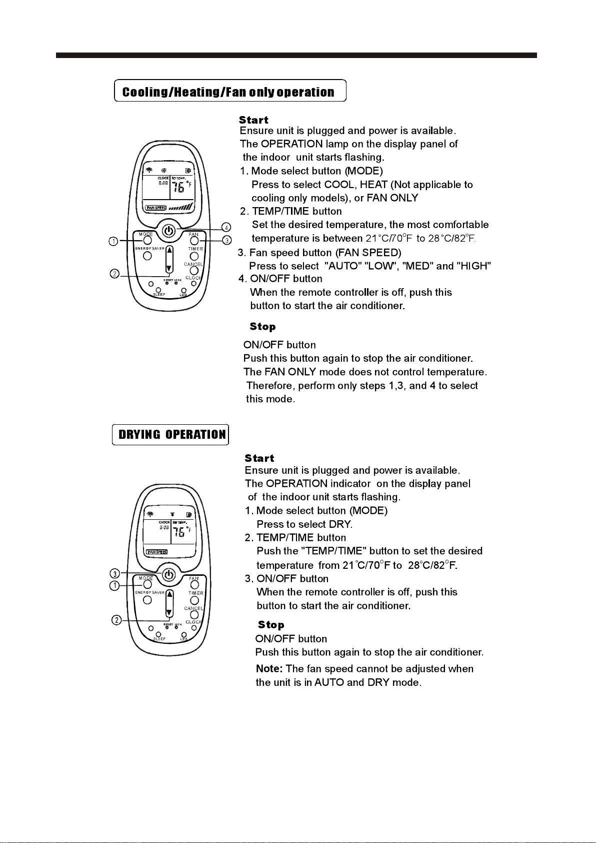
TO SELECT THE OPERATING MODE:
To choose operating mode, press Mode button.Each
time you press the button, a mode is selected in a
sequence that goes from Auto, Cool, Dry ,heat(cooling
only models without)and Fan. The indicator light beside
will be illuminated and remained on once the mode is
selected.
The unit will initiate automatically the Energy Saver
function under Cool, Dry, Auto(only Auto-Cooling and
Auto-Fan) modes.
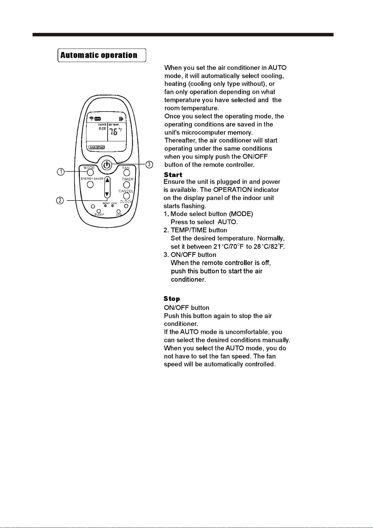
To operate on Auto feature:
When you set the air conditioner in AUTO mode, it will
automatically select cooling, heating(cooling only models
without), or fan only operation depending on what
temperature you have selected and the room temperature.
The air conditioner will control room temperature
automatically round the temperature point set by you.
In this mode, the fan speed cannot be adjusted, it starts
automatically at a speed according to the room
temperature.
To operate on Fan Only:
Use this function only when cooling is not desired,such
as for
room air circulation or to exhaust stale air(on
some models). (Remember to open the vent during this
function, but keep it closed during cooling for maximum
cooling efficiency.) You can choose any fan speed you
prefer.
During this function, the display will show the actual
room temperature, not the set temperature as in the
cooling mode.
In Fan only mode ,the temperature is not adjusted.
To operate on Dry mode:
In this mode, the air conditioner will generally operate
in the form of a dehumidifier. Since the conditioned
space is a closed or sealed area, some degree of
cooling will continue.
SLEEP FEATURE:
Press Sleep button to initiate the sleep mode. In
this mode the selected temperature will increase
(cooling) or decrease (heating) by 2 F/1(or 2)
OO
C 30
minutes after the mode is selected.T he t emperature
will then increase (cooling) or decrease (heating) by
another 2 F/1(or 2)
OO
C after an additional 30 minutes.
T his n ew t emperature w ill be m aintained f or 6 h ours
beforei tr eturnsto th e originallyse lectedtem perature.
This ends the Sleep mode and the unit will continue
t o operate as originally programmed. The Sleep
mode program can be cancelled at any time during
operation by pressing the Sleep button again.
Press Check filter button to initiate this feature.
This feature is a reminder to clean the Air Filter for
more efficient operation. The LED(light) will
illuminate after 250 hours of operation. To reset after
cleaning the filter, press the Check Filter button and
the light will go off.
CHECK FILTER FEATURE:
ENERGY SAVER FEATURE:
Press Energy saver button to initiate this function.
This function is available on COOL, DRY, AUTO
(only AUTO-COOLING and AUTO-FAN) modes.The
fan will continue to run for 3 minutes after the
compressor shuts off.The fan then cycles on for 2
minutes at 10 minute intervals until the room
temperature is above the set temperature, at which
time the compressor turns back on and Cooling
Starts.
FOLLOW ME FEATURE:(on some models)
Light flashing
Follow
Me
This feature can be activated from the remote
control ONLY. The remote control serves as
a remote thermostat allowing for the precise
temperature control at its location.
To activate the Follow Me feature, point the remote
control towards the unit and press the Follow Me
button. T
he remote display is actual temperature at
its location. The remote control will send this signal
to the air conditioner every 3 minutes interval until
press the Follow Me button again.
If the unit does not
receive the Follow Me signal during any 7 minutes
interval, the unit will beep to indicate the Follow Me
mode has ended.
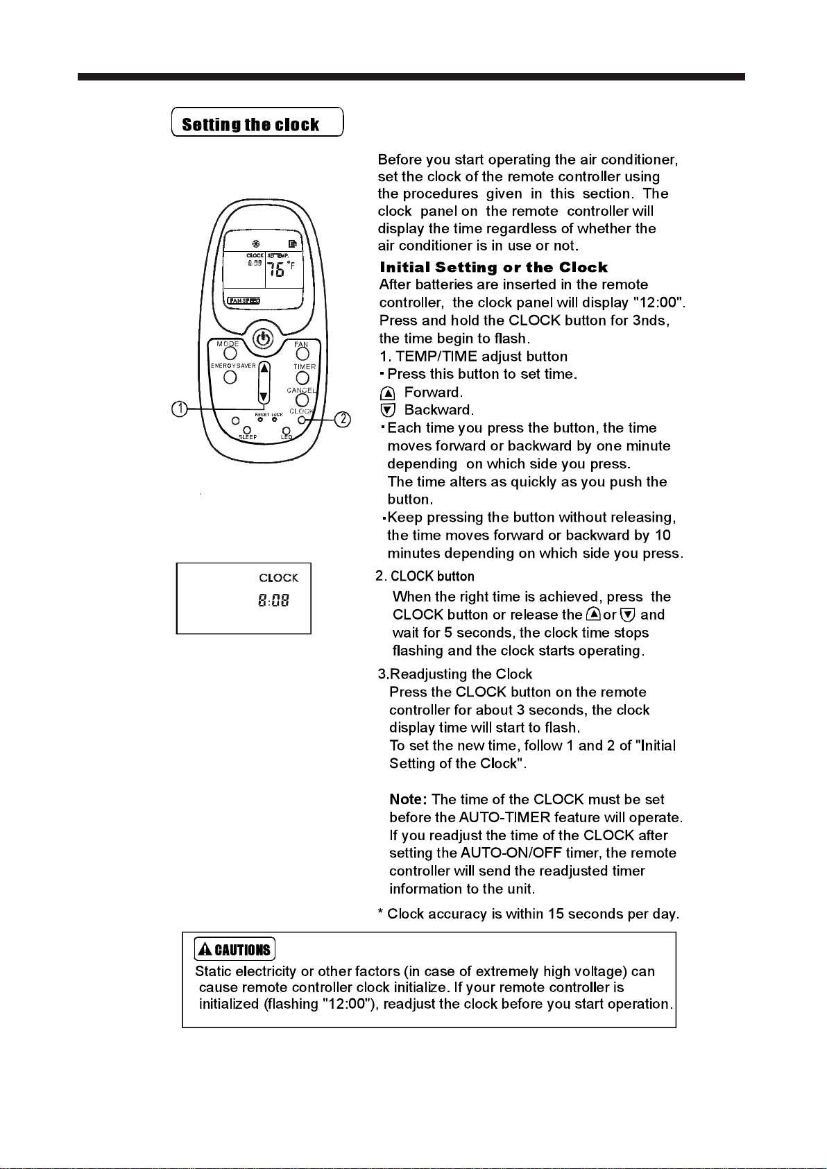
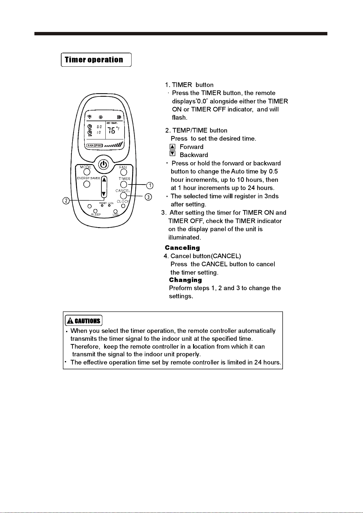
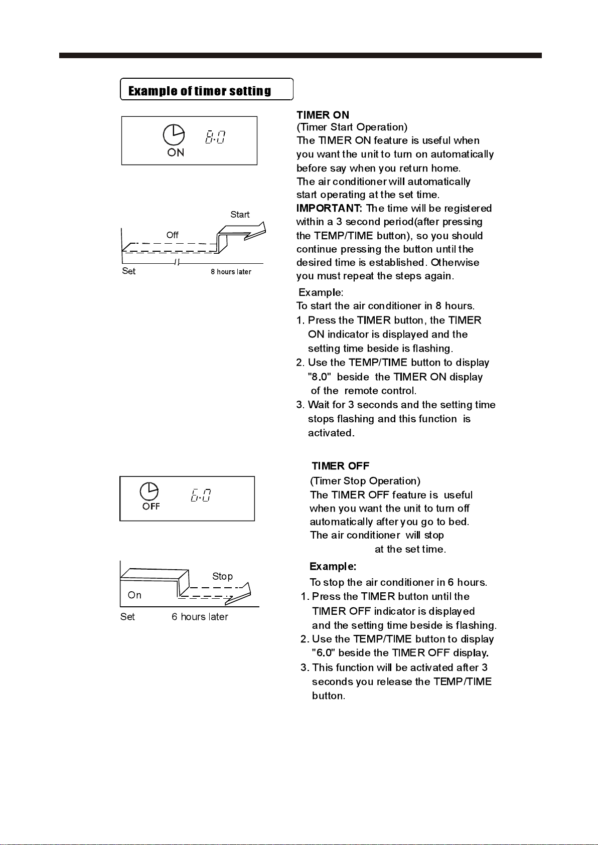
When the unit is on or off, first press Timer button, the
TIMER ON indicator light illuminates. It indicates the Auto
Start program is initiated.
When the time of TIMER ON is displayed
,press the Timer
button again, the TIMER OFF indicator light illuminates.
It indicates the Auto Stop program is initiated.
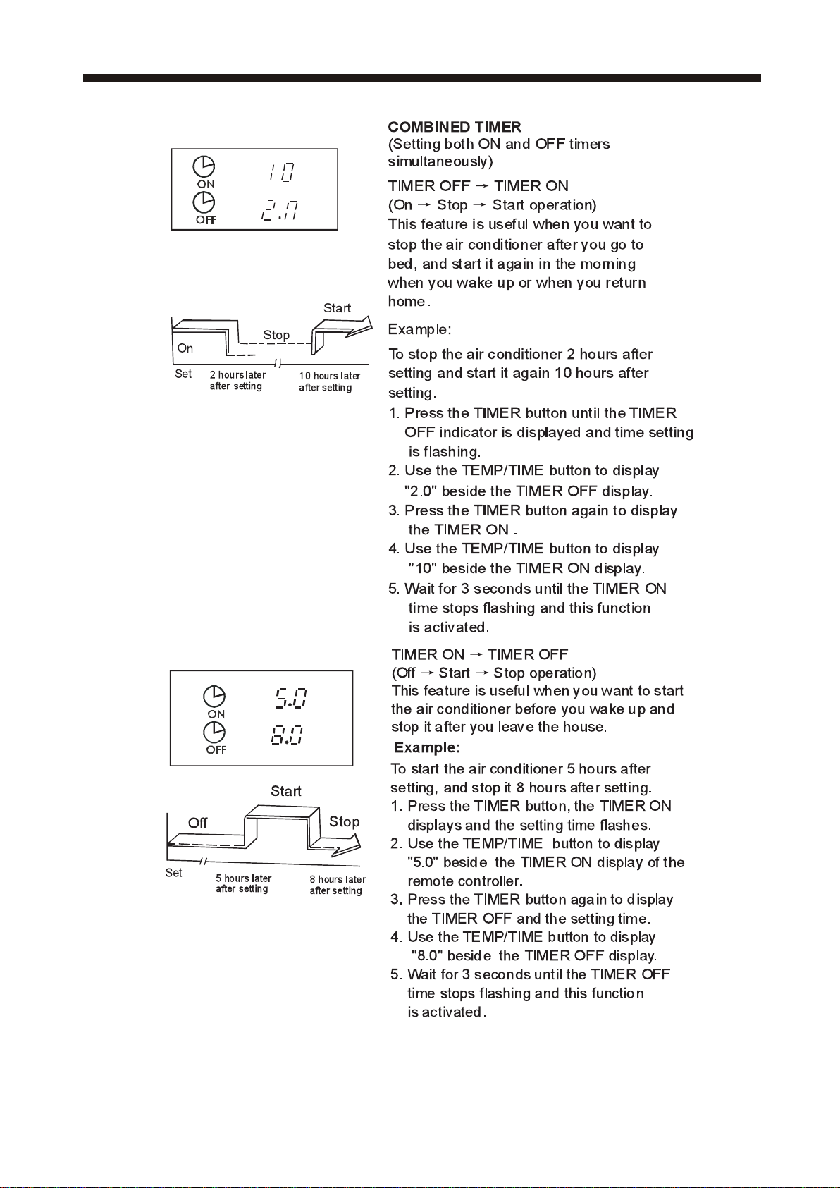
Press or hold the UP or DOWN button to change the Auto
time by 0.5 hour increments, up to 10 hours,then at 1 hour
increments up to 24 hours.The control will count down the
time remaining until start.
The selected time will register in 5 seconds, and the system
will automatically revert back to display the previous
temperature setting or room temperature when the unit is
on.(when the unit is off,there is no display.)
Turning the unit ON or OFF at any time or adjusting the
timer setting to 0.0 will cancel the Auto Start/Stop timed
program.
TIMER: AUTO START/STOP FEATURE:
AIR CONDITIONER FEATURES
Displays
OO
Shows the set temperature in C or F and the
Auto-timer settings.While on Fan only mode,it shows
the room temperature.
DISPLAYS:
-Evaporator temperature sensor error-Unplug the
unit and plug it back in.If error repeats, call for
service.
NOTE: is displayed as shown in the left picture.
HS -Electric heating sensor error-Unplug the unit and
plug it back in.If error repeats, call for service.
Error codes:
AS-Room temperature sensor error-Unplug the unit
and plug it back in.If error repeats, call for service.
NOTE:In Fan only mode,it will display LO or HI .
If the power cuts off unexpectedly, the unit will
automatically restart to the previous function
setting when the power resumes
DISPLAYS:
NOTE:
Now that you have mastered the operating procedure,
here are more features in your control that you should
become familiar with.
The Cool circuit has an automatic 3 minute time
delayed start if the unit is turned off and on quickly.
This prevents overheating of the compressor and
possible circuit breaker tripping.The fan will
continue to run during this time.
The control is capable of displaying temperature in
degrees Fahrenheit or degrees Celsius. To convert
from one to the other, press and hold the Left and
Right Temp/Timer buttons at the same time, for 3
seconds.
CAUTION
Clean your air conditioner occasionally to keep it looking
new. Be sure to unplug the unit before cleaning to
prevent chock or fire hazards.
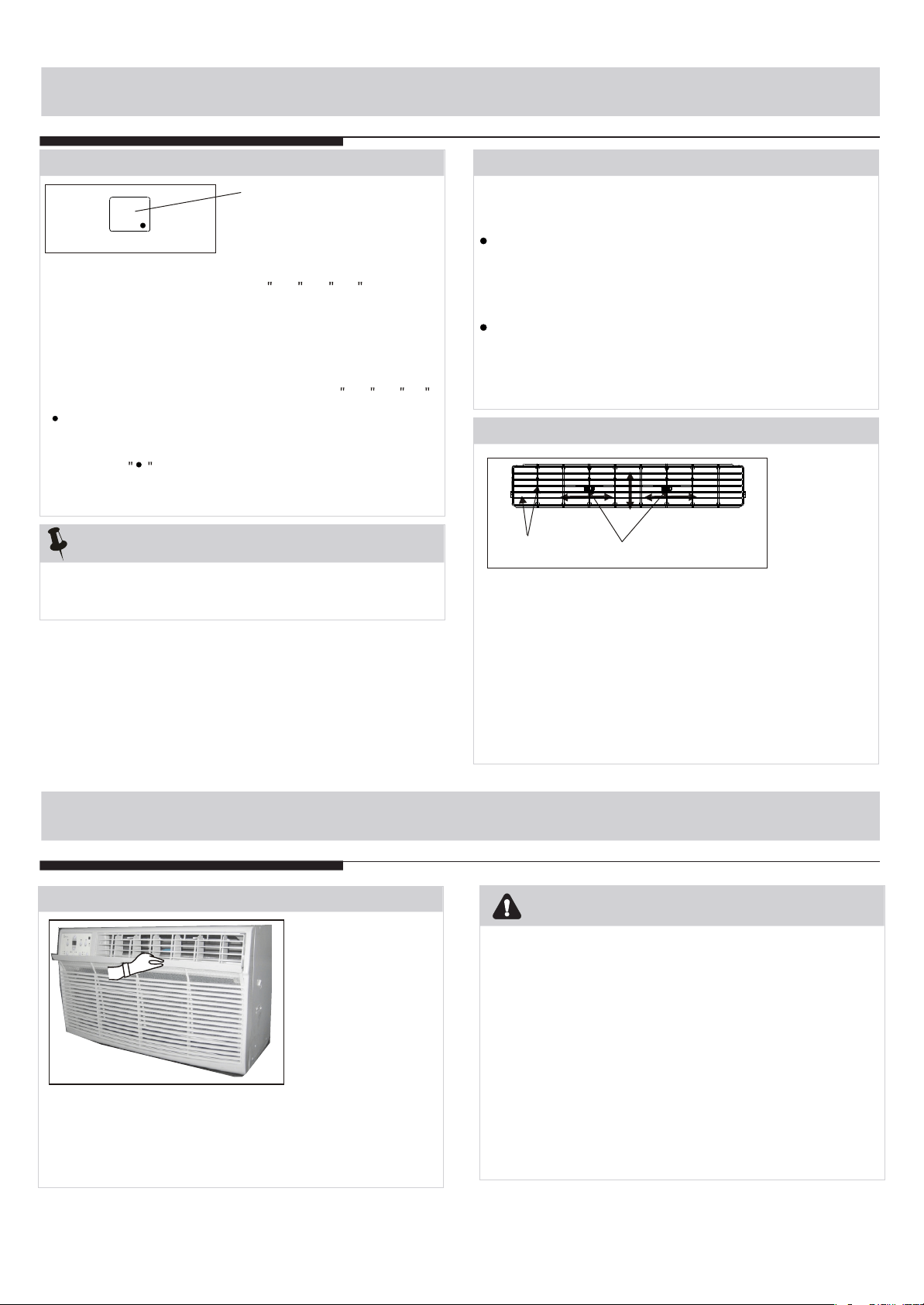
Air Filter Cleaning
The air filter should be checked at least once a month to see
if cleaning is necessary. Trapped particles in the filter can
build up and cause an accumulation of frost on the cooling
coils.
20
Air Direction(4- way)
Air directional louvers control air flow direction.Your air
conditioner has the 4-way directional system described
below.The louvers will allow you to direct the air flow Up
or Horizontal, and Left or Right throughout the room as
needed.Use the center handles to adjust the air
directional louvers side-to-side until the desired Left or
Right direction is obtained.Pivot horizontal louvers with
your fingertips until the desired Up or Horizontal
direction is obtained.There are a total of 4 possible air
directional orientations available with this system.
ADDITIONAL THINGS YOU SHOULD KNOW
Air Directional Louvers
CARE AND CLEANING
Center handles
Louvers
CARE AND CLEANING
Air Filter Cleaning
Take the filter by the center and pull up and out.
Wash the filter using liquid dishwashing detergent and warm
water. Rinse filter thoroughly. Gently shake excess water
from the filter. Be sure the filter is thoroughly dry before
replacing. Or, instead of washing you may vacuum the filter
clean.
Note: Never use hot water over 40 C(104 F) to cl ean th e
a i r fil ter. Never attempt to operate the unit without the air
filter.
Winter Storage
If you plan to store the air conditioner during the winter,
remove it carefully from the window according to the
installation instructions. Cover it with plastic or return it to
the original carton.
Cabinet Cleaning
Be sure to unplug the air conditioner to prevent shock or fire
hazard. The cabinet and front may be dusted with an oil-free
cloth or washed with a cloth dampened in a solution of warm
water and mild liquid dishwashing detergent. Rinse thoroughly
and wipe dry.
Never use harsh cleaners, wax or polish on the cabinet front.
Be sure to wring excess water from the cloth before wiping
around the controls. Excess water in or around the controls
may cause damage to the air conditioner.
Plug in air conditioner.
TROUBLESHOOTING TIPS
Before calling for service, review this list. It may save your time and expense. This list includes common
occurrences that are not the result of defective workman-ship or materials in this appliance.
Solution
Air conditioner
does not start
Wall plug disconnected. Push plug firmly into wall outlet.
House fuse blown or circuit breaker tripped. Replace fuse with time delay type or
reset circuit breaker.
Plug Current Device Tripped. Press the RESET button.
Problem
Air from unit does
not feel cold
enough
Set to a Lower temperature.
OO
Room temperature below 62 F(17 C ). Cooling may not occur until room temperature
OO
rises above 62 F(17 C).
Thermostat set too cold for night-time cooling. To defrost the coil, set to FAN ONLY
mode. Then, set temperature to a Higher setting.
Temperature sensing behind air filter element touching cold coil. Keep it from the cold
coil.
Air filter may be dirty. Clean filter. Refer to Care and Cleaning section. To defrost,
set to FAN ONLY mode.
Power is OFF. Turn power ON.
Air conditioner
cooling, but room
is too warm- ice
forming on cooling
coil behind
decorative front.
OO
Outdoor temperature below 64 F(18 C). To defrost the coil, set FAN ONLY mode.
Compressor stopped when changing modes. Wait for 3 minutes after set to the COOL
mode.
21
Energy Saving Note:
In order to reach the maximum energy saving and comfort,
it is recommended to use a cover to insulate the unit when
the unit is not in use. The recommended size for the unit is
24.4 x14.8 x2.2 (WxHxD).
TROUBLESHOOTING TIPS
Solution
Problem
Dirty air filter- air restricted. Clean air filter. Refer to Care and Cleaning section.
Unit recently turned on in hot room. Allow additional time to remove Stored heat from
walls, ceiling, floor and furniture.
Air conditioner
cooling, but room
is too warm- NO
ice forming on
cooling coil behind
decorative front.
Temperature is set too High, set temperature to a Lower setting.
Air directional louvers positioned improperly. Position louvers for better air distribution.
Front of units is blocked by drapes, blinds, furniture, etc. - restricts air distribution.
Clear blockage in front of unit.
Doors, windows, registers, etc. Open- cold air escapes. Close doors, windows, registers.
Air conditioner turns on
and off rapidly
Noise when unit is
cooling
Water dripping
INSIDE when
unit is cooling.
Improper installation. Tilt air conditioner slightly to the outside to allow water drainage.
Refer to installation instructions - check with installer.
Dirty air filter- air restricted. Clean air filter.
Air movement sound. This is normal . If too loud, set to a slower FAN setting.
Outside temperature extremely hot. Set FAN speed to a Higher setting to bring air past
cooling coils more frequently.
Window vibration - poor installation. Refer to installation instructions or check with installer.
Water dripping
OUTSIDE when
unit is cooling.
Remote Sensing
Deactivating
Prematurely
(some models)
Remote control not located within range. Place remote control within 20 feet & 180 ,
radius of the front of the unit.
Remote control signal obstructed. Remove obstruction.
Room too cold
Set temperature too low. Increase set temperature.
Unit removing large quantity of moisture from humid room. This is normal during
excessively humid days.
22
23
Press this botton to turn unit on or off.
NOTE: The unit will initiate automatically the Energy Saver
function under Cool, Dry, Auto (only Auto-Cooling and Auto-
Fan) modes.
This funtion is available on COOL,
DRY, AUTO (only AUTO-COOLING and AUTO-FAN) modes.
The fan will continue to run for 3 minutes after the compressor
shuts off. The fan then cycles on for 2 minutes at 10 minutes
intervals until the room temperature is above the set temperature,
at which time the compressor turns back on and Cooling
Starts.
FOLLOW ME
24
Follow Me
increase
FOLLOW ME
Press
Follow
Me
Follow
Me
6
25
FOLLOW ME
FOLLOW ME
26
PP
Heat
mode.
set the
27
FOLLOW ME
28
FOLLOW ME
29
FOLLOW ME
FOLLOW ME
30
FOLLOW ME
31
automatically
32
33

Air Conditioner Limited Warranty
Your product is protected by this Limited Warranty:
Warranty service must be obtained from Midea Consumer Services or an authorized Midea servicer.
Warranty
• Two Year Limited Warranty from original purchase date. Five Year Limited Sealed System (Sealed system
includes components containing refrigerant) Warranty from original purchase date.
Midea, through its authorized servicers will:
• Pay all costs for reparing or replacing parts of this appliance which prove to be defective in materials or workmanship.
Consumer will be responsible for:
• Diagnostics, removal, transportation and reinstallation cost required because of service.
• Costs of service calls that are a result of items listed under NORMAL RESPONSABILITIES OF THE CONSUMER**
Midea replacement parts shall be used and will be warranted only for the original warranty.
NORMAL RESPONSABILITIES OF THE CONSUMER**
This warranty applies only to products in ordinary household use, and the consumer is responsible for the items
listed below:
1. Proper use of the appliance in acordance with instructions provided with the product.
2. Routine maintenance and cleaning necessary to keep the good working condition.
3. Proper installation by an authorized service professional in accordance with instructions provided with the
appliance and in accordance with all local plumbing, electrical and/or gas codes.
4. Proper connection to a grouded power supply of sufficient voltage, replacement of blown fuses, repair of loosen
connections or defects in house wiring.
5. Expenses for making the appliance accessible for servicing.
6. Damages to finish after intallation.
EXCLUSIONS
This warranty does not cover the following:
1) Failure caused by damage to the unit while in your possesion (other than damage caused by defect or
malfunction), by its improper installation, or by unreasonable use of the unit, including without limitation, failure to
provide reasonable and necessary maintenance or to follow the written installation and Operating Instructions.
2) Damages caused by services performed by persons other than authorized Midea costumer service; or external
causes such as abuse, misuse, inadequate power supply or acts of God.
3) If the unit is put to commercial, business, rental, or other use or application other than for consumer use, we make
no warranties, express or implied, including but not limited to, any implied warranty of merchantability or fitness
for use or purpose.
4) Products without original serial numbers or products that have serial numbers which have been altered or cannot
be readily determined.
NOTE: Some states do not allow the exclusions or limitation of incidental or consequential damages. So this
limitation or exclusion may not apply to you.
IF YOU NEED SERVICE
Keep your bill of sale, delivery slip, or some other appropriate payment Record.
The date on the bill establishes the warranty period, should service be required.
If service is performed, its your best interest to obtain and keep all receipts.
This written warranty gives you specific legal rights. You may also have other rights that vary from state to state.
Service under this warranty must be obtained by following these steps, in order:
1) Contact Midea Consumer Services or an authorized Midea services at 1 866 646 4332.
2) If there is a question as to where to obtain service, contact our consumer relations Departament.
Warranty
Warranty