Loading ...
Loading ...
Loading ...
– 16 –
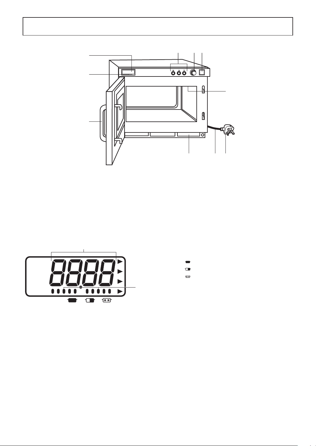
Outline Diagram of NE-1843
❼
❻
❽
❶
❷
❸ ❹
❺
❾ ❿
1 Digital Display Window (see below)
2 Power Level Indicator Display
3 Power Level Selector Buttons
4 Timer Dial
5 Start Button
6 Door Handle
Air Filter
Splatter Shield (top of inner cavity)
Power Cord
Power Plug
Caution label is attached on the outside surface.
A — Heating Time Display (min. sec.)
B — Power Level Indicator
:
HIGH
: MEDIUM
: DEFROST
A
B
Loading ...
Loading ...
Loading ...