
1
2
3
4
5
6
7
8
9
1
0
1
1
1
2
1
3
1
4
1
5
1
6
1
7
1
8
1
9
2
0
2
1
2
2
2
3
2
4
2
5
2
6
2
7
2
8
2
9
3
0
3
1
MB1303
Recreation Supply Inc.
Model No.
HFT
P.O. BOX 181
BODYCRAFT
is a division of Recreation Supply
Sunbury, OH 43074

1
CongratulationsandThankYou!
Thankyouforselectingthe
BODYCRAFTHFTStrengthTraining
System
.TheBODYCRAFTHFToffersanimpressivearrayofstrength
trainingexercisestodevelopeverymajormusclegroupofthebody.
Whetheryourgoaliscardiovascularfitness,ashapely,tonedbodyor
dramaticmusclesizeandstrength,theBODYCRAFTHFTwillhelpyou
achievetheresultsyouwant.Foryoursafetyandbenefit,readthismanual
andtheaccompanyingliteraturebeforeusingtheBODYCRAFTHFT.Keep
thismanualforfuturereference.Ifyouhaveadditionalquestions,please
contactyourlocalBODYCRAFTHFTDealerorBODYCRAFT
at
info@bodycraft.comor800-990-5556
Monday–Friday,9amuntil5pmEST.
ImportantSafetyNotes
Thereisariskassumedbyindividualswhousethistypeofequipment.
Beforebeginningthisoranyotherexerciseprogramconsultyourphysician.
Thisisespeciallyimportantforindividualsovertheageof35orpersons
withpre-existinghealthproblems.RecreationSupply,Inc.assumesno
responsibilityforpersonalinjuryorpropertydamagesustainedbyor
throughuseofthisproduct.
1.Thisproductmustbeassembledonaflat,levelsurfacetoassureitsproperfunction.
2.Cleanpadsandframeonaregularbasis.Werecommendwarm,soapywater.
Donotuseharshorabrasivechemicals.
3.Inspectandtightenallpartsbeforeeveryuse.Replaceanyworn
partsimmediately.Failuretodosomayresultinseriousinjury.
4.KeepchildrenawayfromtheBODYCRAFTEliteatalltimes.
5.Keepyourhandsawayfromcablesandpulleysduringoperation.
6.Keepyourhandsawayfrommovingpartsotherthanthedesignatedhandles.
7.Whenmakingadjustmentswiththepop-pin,makesurethespring
pinisfullyengaged.
8.Makecertainallcablesareseatedwithinthepulleysbeforeeveryuse.
9.Exercisewithcaretoavoidinjury.
10.IfyouareunsureabouttheproperuseoftheBODYCRAFTHFTStrengthTraining
SystemcallyourlocalBODYCRAFTdealerorourcustomerservicedepartment.
PartsMissingorDamaged?
Asaqualityhomegymsupplierwearecommittedtoyourcompletesatisfaction.
Ifyoufindmissingordamagedparts,wewillguaranteeyourcompletesatisfaction
throughourauthorizeddealerservicecentersorourhomeofficecustomerservice
department.PleasecontactyourlocaldealerforassistanceorBODYCRAFTat
service@bodycraft.com or 800-990-5556 (9 AM - 5 PM) EST. Our trained
technicianswillprovideimmediateassistancetoyou.
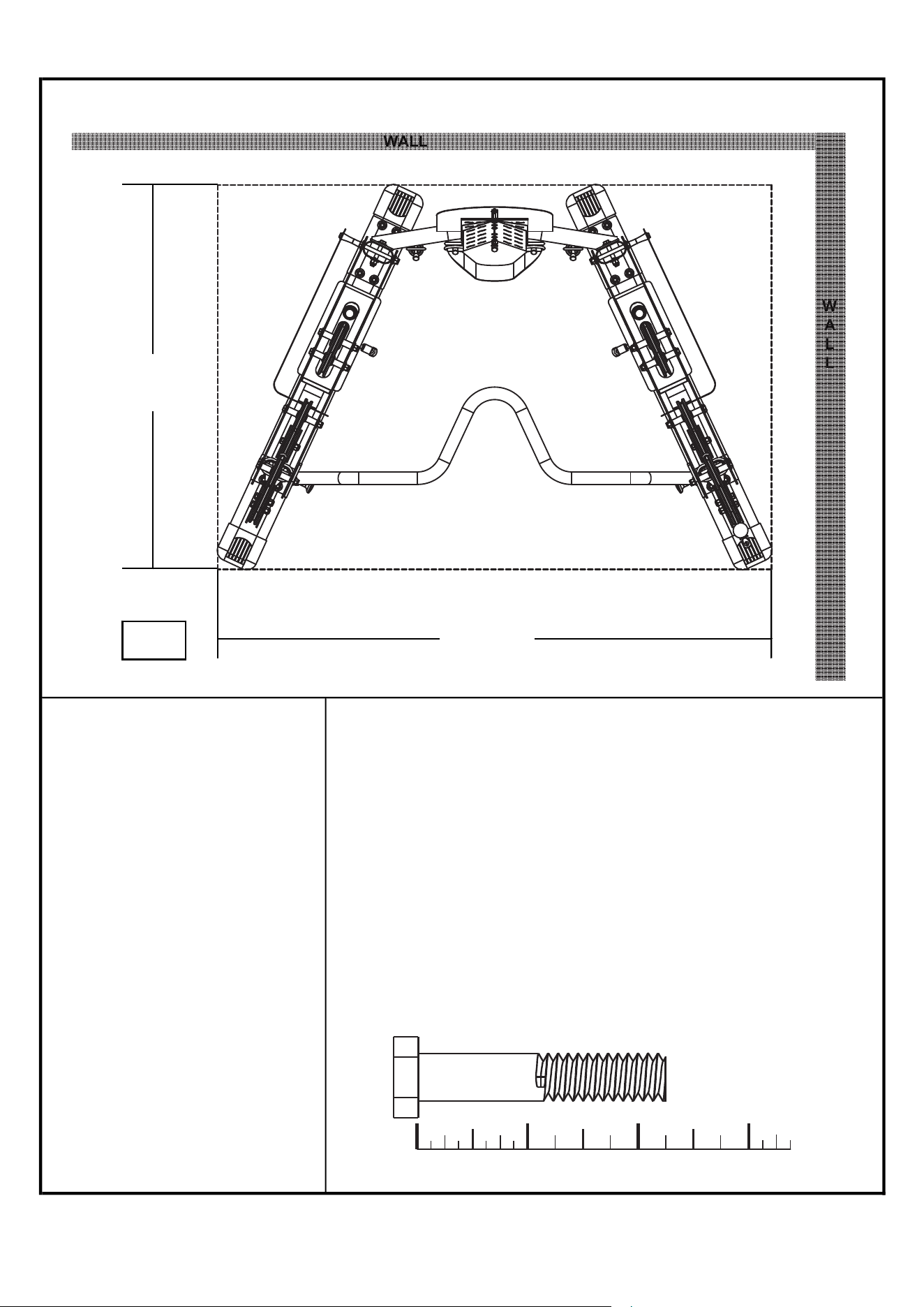
Gym Placement Planner
If possible, please take advantage of the corner fit design.
WALL
W
A
L
L
38.65"
HEIGHT
81.68"
55.64"
Important Notes and Tips:
Ratchet
9/16" Socket
3/4" Socket
9/16" Combination Wrench
3/4" Combination Wrench
Adjustable Wrench
Rubber Mallet
Metric Allen Key Set
Silicone Spray
Window Cleaner or Water
2
Recommended Tools
for Assembly
1. Do not tighten any bolts until instructed.
2. Two people are reguired for the safe assembly
of the gym.
3. Use window cleaner or water to assist with roller
pad installation.
4. Use silicone lubricant on guide rods prior to weight
plate installation.
5. Carefully install plastic caps using a rubber mallet.
6. For your convenlence, rulers are displayed throughout
this manual.
7. When measuring bolt lengths, only measure the shank.
i.e. 2-1/4" Hex Bolt
0 1/4 1/2 3/4 1/4 1/2 3/4 1/4 1/2 3/4 1/41" 2" 3"
1
2
3
4
5
6
7
8
9
1
0
1
1
1
2
1
3
1
4
1
5
1
6
1
7
1
8
1
9
2
0
2
1
2
2
2
3
2
4
2
5
2
6
2
7
2
8
2
9
3
0
3
1
1
2
3
4
5
6
7
8
9
1
0
1
1
1
2
1
3
1
4
1
5
1
6
1
7
1
8
1
9
2
0
2
1
2
2
2
3
2
4
2
5
2
6
2
7
2
8
2
9
3
0
3
1
16L
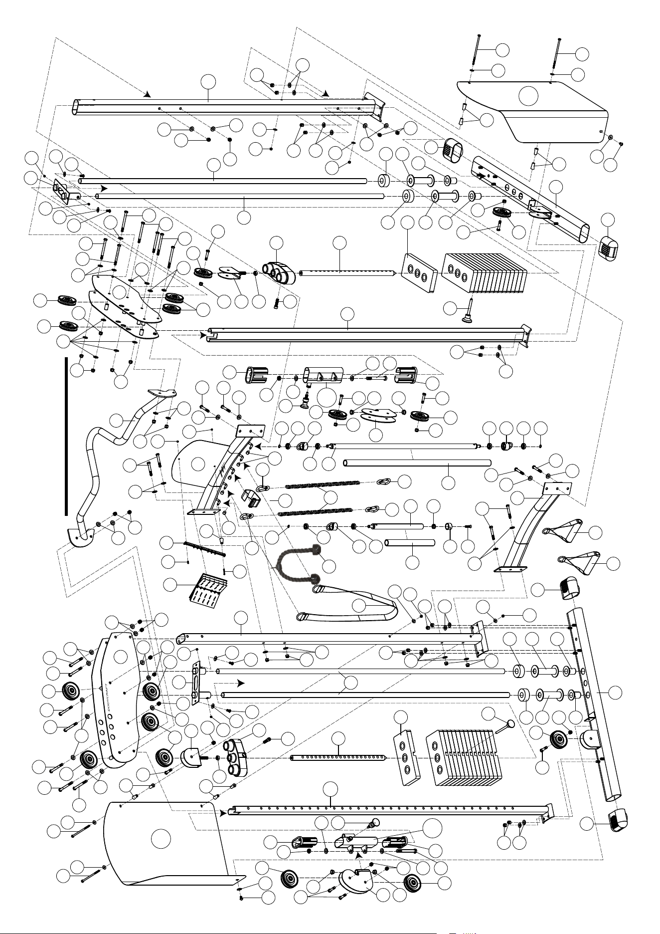
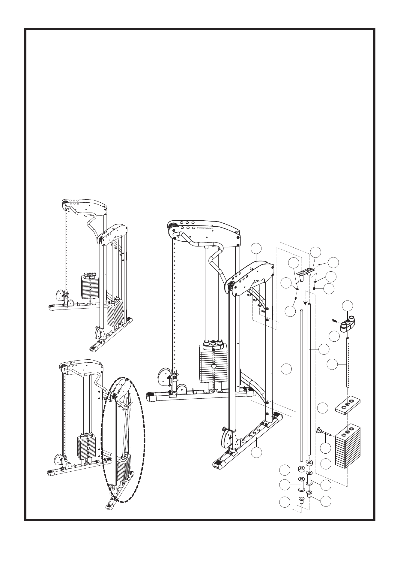
OVERVIEW
3
6R
36
36
18
63
69
36
69
63
63
54
66
51
51
51
51
51
50
50
43
43
71
53
54
66
10R
15R
37
37
49
61
67
35
20
61
17
44
44
53
55
1
38
38
52
52
62
62
52
62
9
70
32
32
62
66
66
70
68
62
68
48
58
34
33
34
34
47
29
34
39
12
40
73
42
57
45
25
46
31
30
43
26
8
59
52
69
63
62
36
50
51
36
19
36
18
69
71
48
41
69
24
53
36
51
53
50
5
3L
20
23
21
38
43
66
54
65
55
1
22
22
23
24
38
5
51
63
64
60
56
63
63
63
36
63
69
69
6L
37
35
61
49
67
61
53
44
69
17
69
36
53
37
36
7
72
72
52
62
52
62
63
28
56
64
56
60
60
14
64
68
62
41
36
22
19
2R
4
5
21
23
22
23
24
53
68
69
24
36
69
65
36
36
69
62
68
69
63
63
63
69
47
46
45
25
45
13
45
68
62
25
45
46
44
69
64
56
60
14
70
68
62
62
68
66
66
66
54
43
11L
68
62
70
68
68
4
62
62
45
1
2R
3L
4
5
6R
6L
7
8
9
10R
11L
12
13
14
15R
16L
17
18
19
20
21
22
23
24
25
26
27
28
29
30
31
32
33
34
35
2
1
1
2
4
1
1
1
1
1
1
1
1
1
2
1
1
2
2
2
2
28
4
4
4
3
1
2
1
1
1
1
2
2
4
2
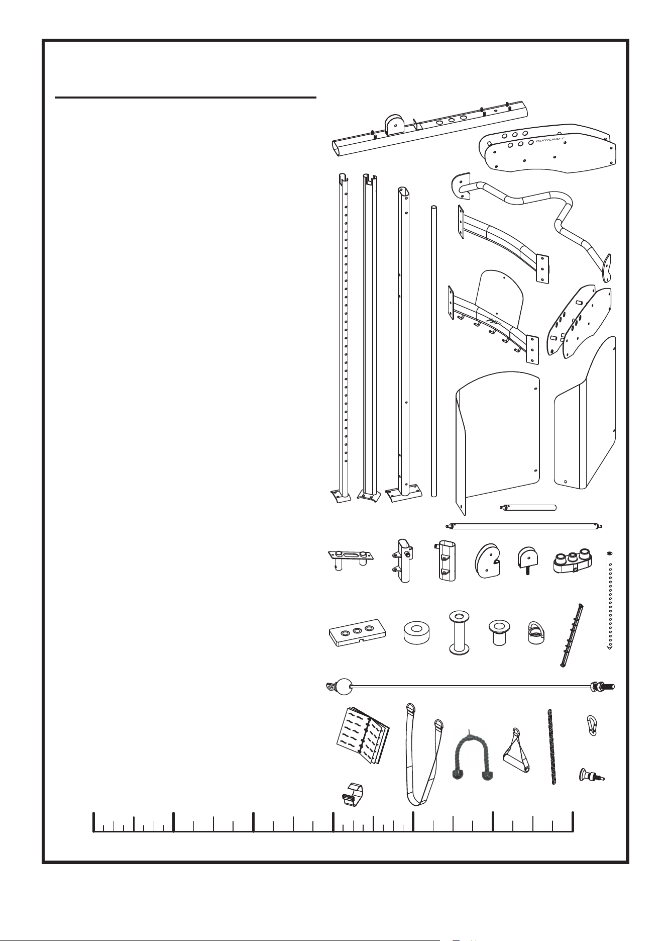
BASE FRAME LEG
UPRIGHT FRAME - RIGHT
UPRIGHT FRAME - LEFT
REAR UPRIGHT FRAME
GUIDE ROD
TOP FRAME - RIGHT
TOP FRAME - LEFT
CHIP - UP BAR
TOP CROSS SUPPORT
BOTTOM CROSS SUPPORT
WEIGHT PANEL - RIGHT
WEIGHT PANEL - LEFT
SPORT BAR
LONG BAR
TOP GUIDE ROD HOLDER
PULLEY HEIGHT ADJUSTER
- RIGHT (pre-assembled)
PULLEY HEIGHT ADJUSTER
- LEFT (pre-assembled)
ROTATING PULLEY HOLDER
(pre-assembled)
PULLEY BLOCK
TOP PLATE
SELECTOR ROD
10 LB. WEIGHT PLATE
RUBBER DONUT
STACK SPACER
PLASTIC GUIDE ROD
HOLDER
SPORT BAR COLLAR
(pre-assembled)
EXERCISE BOOK HOLDER
(pre-assembled)
CABLE
EXERCISE BOOK (pre-assembled)
ANKLE STRAP
CHIN ASSIST STRAP
TRICEP ROPE
SINGLE HANDLE
CHAIN
SNAP HOOK
POP - PIN (pre-assembled)
PARTS LIST
NO. DESCRIPTION QTY.
0
1/4
1/2
3/4 1/4
1/2
3/4 1/4
1/2
3/4 1/4
1/2
3/4
1" 2" 3" 4"
1/4
1/2
3/4 1/4
1/2
3/4
5" 6"
(inch)
4
1
6R
6L
7
8
10R
11L
9
2R 3L 4 5
15R14
12
13
16L 17 18 19
20
21 23 2422 25
26
28
27
30
31
29
32
33
34
35
1
2
3
4
5
6
7
8
9
1
0
1
1
1
2
1
3
1
4
1
5
1
6
1
7
1
8
1
9
2
0
2
1
2
2
2
3
2
4
2
5
2
6
2
7
2
8
2
9
3
0
3
1
1
2
3
4
5
6
7
8
9
1
0
1
1
1
2
1
3
1
4
1
5
1
6
1
7
1
8
1
9
2
0
2
1
2
2
2
3
2
4
2
5
2
6
2
7
2
8
2
9
3
0
3
1
36
37
38
39
40
41
42
43
44
45
46
47
48
49
50
51
52
53
54
55
56
57
58
59
60
61
62
63
64
65
66
67
68
69
70
71
72
73
16
4
4
1
1
2
1
9
4
6
3
5
2
2
4
10
8
8
4
2
4
1
1
1
4
4
28
28
4
2
8
2
20
22
4
2
2
1
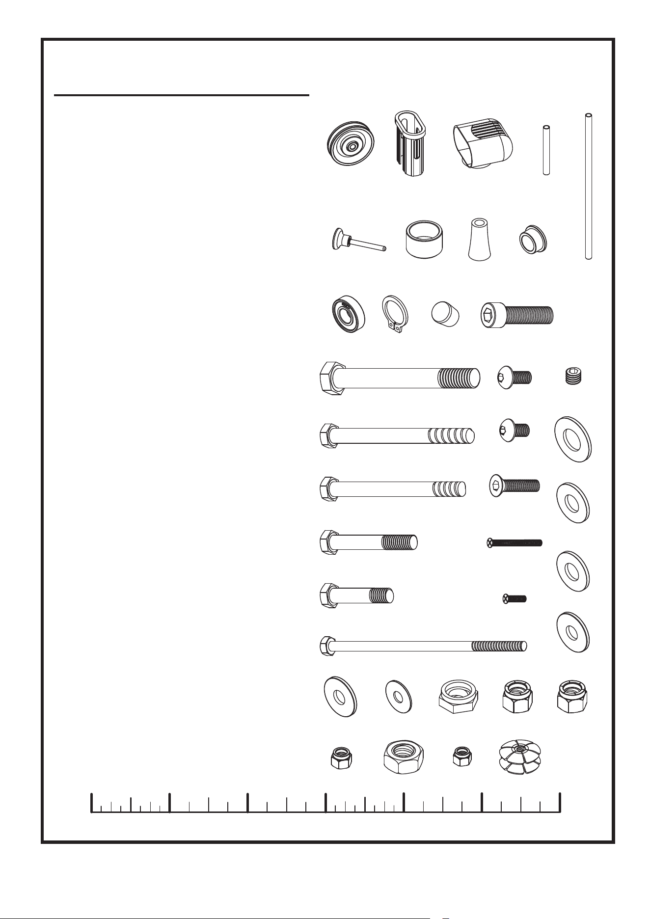
PULLEY
PLASTIC BUSHING
(pre-assembled)
END CAP
1" X 295L FOAM GRIP
(pre-assembled)
1" X 900L FOAM GRIP
(pre-assembled)
SELECTOR PIN
SPACER (pre-assembled)
PLASTIC STUDS
(8 picess pre-assembled)
1/2" BUSHING (pre-assembled)
BEARING (pre-assembled)
C - RING (pre-assembled)
RUBBER COVER (pre-assembled)
TOP PLATE BOLT
1/2" X 4-1/2" HEX BOLT
(pre-assembled)
3/8" X 4-1/4" HEX BOLT
3/8" X 4" BLACK HEX BOLT
3/8" X 2-1/2" HEX BOLT
3/8" X 1-3/4" HEX BOLT
1/4" X 6" HEX BOLT
5/16" X 1/2" BOTTOM HEAD
BOLT
5/16" X 5/8" BOTTOM HEAD
BOLT (pre-assembled)
5/16" X 1-1/4" SUNKEN HEAD
BOLT (pre-assembled)
M4 X 40L SUNKEN HEAD
SCREW (pre-assembled)
M4 X 10L SUNKEN HEAD
SCREW (pre-assembled)
5/16" X 1/4" SET SCREW
(pre-assembled)
1/2" WASHER
(pre-assembled)
3/8" CHROMED WASHER
(16 picess pre-assembled)
3/8" BLACK WASHER
5/16" CHROMED WASHER
(pre-assembled)
5/16" BLACK WASHER
1/4" WASHER
1/2" NYLON NUT (pre-assembled)
3/8" CHROMED NYLON NUT
(8 picess pre-assembled)
3/8" BLACK NYLON NUT
1/4" NYLON NUT
1/2" NUT (pre-assembled)
M4 NYLON NUT (pre-assembled)
1" NUT (pre-assembled)
PARTS LIST
NO. DESCRIPTION QTY.
0
1/4
1/2
3/4 1/4
1/2
3/4 1/4
1/2
3/4 1/4
1/2
3/4
1" 2" 3" 4"
1/4
1/2
3/4 1/4
1/2
3/4
5" 6"
(inch)
5
41 42 43 44
45 46 47 48
49 55
56
60
61
62
63
66 67
70 71 72
68
73
57
58
59
50
51
52
53
54
36 37 38 39
40
64
65 69
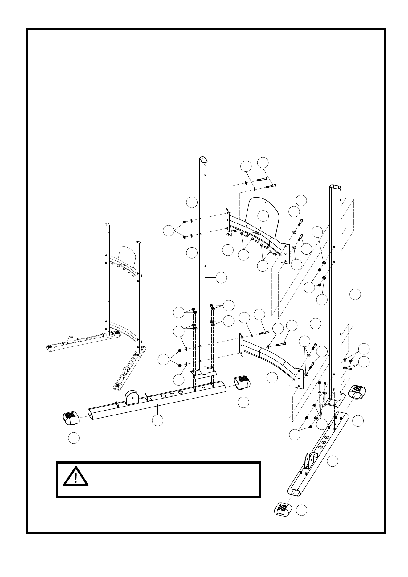
STEP 1 Assemble Upright Frame
6
TWO PEOPLE ARE REQUIRED TO ASSEMBLE THIS STEP.
1. Cap two End Caps (38) to the Base Frame Leg (1). Attach Rear Upright Frame
(4) to the Base Frame Leg (1) using eight 3/8" Chromed Washers (62), and
eight 3/8" Chromed Nylon Nuts (68).
2. Attach Top Cross Support (8) to the Rear Upright Frame (4) using four 3/8" X 2-
1/2" Hex Bolts (52), eight 3/8" Chromed Washers (62), and four 3/8" Chromed
Nylon Nuts (68).
3. Attach Bottom Cross Support (9) to
the Rear Upright Frames (4) using
four 3/8" X 2-1/2" Hex Bolts (52),
eight 3/8" Chromed Washers
(62), and four 3/8" Chromed
Nylon Nuts (68).
1
38
38
38
38
1
9
47
62
52
62
62
68
47
4
8
4
62
62
68
68
62
52
62
68
62
52
62
68
62
62
52
62
52
62
52
52
62
68
68
47
62
TO EASE THE ASSEMBLY PROCESS.
DO NOT TIGHTEN ANY BOLTS UNTIL
INSTRUCTED.
1
2
3
4
5
6
7
8
9
1
0
1
1
1
2
1
3
1
4
1
5
1
6
1
7
1
8
1
9
2
0
2
1
2
2
2
3
2
4
2
5
2
6
2
7
2
8
2
9
3
0
3
1
1
2
3
4
5
6
7
8
9
1
0
1
1
1
2
1
3
1
4
1
5
1
6
1
7
1
8
1
9
2
0
2
1
2
2
2
3
2
4
2
5
2
6
2
7
2
8
2
9
3
0
3
1
1
2
3
4
5
6
7
8
9
1
0
1
1
1
2
1
3
1
4
1
5
1
6
1
7
1
8
1
9
2
0
2
1
2
2
2
3
2
4
2
5
2
6
2
7
2
8
2
9
3
0
3
1
1
2
3
4
5
6
7
8
9
1
0
1
1
1
2
1
3
1
4
1
5
1
6
1
7
1
8
1
9
2
0
2
1
2
2
2
3
2
4
2
5
2
6
2
7
2
8
2
9
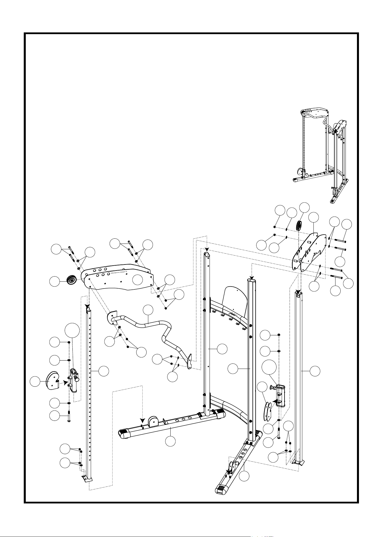
STEP 2 Assemble Top Frame
7
1. Attach Right & Left Upright Frame (2R & 3L) to the two Base Frame Legs (1) using
four 3/8" Chromed Washers (62), and four 3/8" Chromed Nylon Nuts (68).
2. Attach two Rotating Pulley Holders (17) to the Right & Left Pulley Height Adjuster
(15R & 16L) using two 1/2" X 4-1/4" Hex Bolts (49), four 1/2" Washers (61), and two
1/2" Nylon Nuts (67). Slide Right & Left Pulley Height Adjuster
(15R & 16L) to the Right & Left Upright Frame (2R & 3L).
3. TWO PEOPLE ARE REQUIRED TO ASSEMBLE THIS STEP.
Attach Right & Left Top Frame (6R & 7L) to the rear uprights one at a
time using four 3/8" X 4" Black Hex Bolts (51), eight 3/8" Black Washers
(63), four 3/8" Black Nylon Nuts (68). Do Not Tighten.
4. NOTE: TWO PEOPLE ARE REQUIRED TO ASSEMBLE THIS STEP.
To ease assembly, insert bolts and washers in this step from the
outside through the Top Frames and Front Uprights as shown.
Before installing inside washers and nuts install Chin Bar (7) as shown.
Assembly Right & Left Top Frame (6R & 7L) and Right & Left Upright
Frame (2R & 3L), and Chin Bar (7) one at a time using four
3/8" X 4" Black Hex Bolts (51), eight 3/8" Black Washers
(63), four 3/8" Black Nylon Nuts(68). Tighten all the Bolts and
Nuts from the bottom Base Frame Leg to the top.
67
36
50
61
61
49
62
17
15R
16L
63
6R
7
1
1
17
61
67
69
63
69
51
63
63
69
63
3L
36
6
63
63
69
63
50
63
51
69
50
2R
4
4
61
62
49
68
68
51
Slight
Angle
1
2
3
4
5
6
7
8
9
1
0
1
1
1
2
1
3
1
4
1
5
1
6
1
7
1
8
1
9
2
0
2
1
2
2
2
3
2
4
2
5
2
6
2
7
2
8
2
9
3
0
3
1
STEP 3 Assemble Guide Rods
8
1. Insert two Plastic Guide Rod Holders (24) into the holes on the Base Frame Leg (1).
Insert the Guide Rods (5) into the Plastic Guide Rod Holders (24). Slide the Stack
Spacers (23) onto the guide rods, followed by the two Rubber Dounts (22).
NOTE: Do not install STACK SPACERS (23) if you have the optional heavy weight stack
option, 38 WEIGHT PLATES (21). Use STACK SPACERS (23) if you have 28 WEIGHT
PLATES (21).
2. TWO PEOPLE ARE REQUIRED TO ASSEMBLE THIS STEP. With the guides
angled slightly (as shown in fig at bottom left). Slide the Weight Plates (21) onto the
Guide Rods (5), making sure to orient the selector holes toward the front and bottom.
Attach the Top Plate (19) to the Selector Rod (20) using the Top Plate Bolt (48).
Tighten the Top Plate Bolt (48) using a hex key. Slide the Top Plate onto the guide
Rods, running the Selector Rod (41) down through the center holes of the Weight
Plates (21).
3. Attach Top Guide Rod Holder (14) to the top end of Guide Rod (5) and secure to
the top of the Left Top Frame (6L), using two 5/16" X 5/8" Hex
Socken Dome Bolts (56) and two 5/16" Washers (64).
56
48
41
1
6L
19
20
5
5
21
22
23
24
22
23
24
56
64
60
64
60
14
1
2
3
4
5
6
7
8
9
1
0
1
1
1
2
1
3
1
4
1
5
1
6
1
7
1
8
1
9
2
0
2
1
2
2
2
3
2
4
2
5
2
6
2
7
2
8
2
9
1
2
3
4
5
6
7
8
9
1
0
1
1
1
2
1
3
1
4
1
5
1
6
1
7
1
8
1
9
2
0
2
1
2
2
2
3
2
4
2
5
2
6
2
7
2
8
2
9
1
2
3
4
5
6
7
8
9
1
0
1
1
1
2
1
3
1
4
1
5
1
6
1
7
1
8
1
9
2
0
2
1
2
2
2
3
2
4
2
5
2
6
2
7
2
8
2
9
3
0
3
1
P3,P4,P6,P7
P3
P4
P7
P6
1
2
3
4
5
6
7
8
9
1
0
1
1
1
2
1
3
1
4
1
5
1
6
1
7
1
8
1
9
2
0
2
1
2
2
2
3
2
4
2
5
2
6
2
7
2
8
2
9
3
0
3
1
1
2
3
4
5
6
7
8
9
1
0
1
1
1
2
1
3
1
4
1
5
1
6
1
7
1
8
1
9
2
0
2
1
2
2
2
3
2
4
2
5
2
6
2
7
2
8
2
9
3
0
3
1
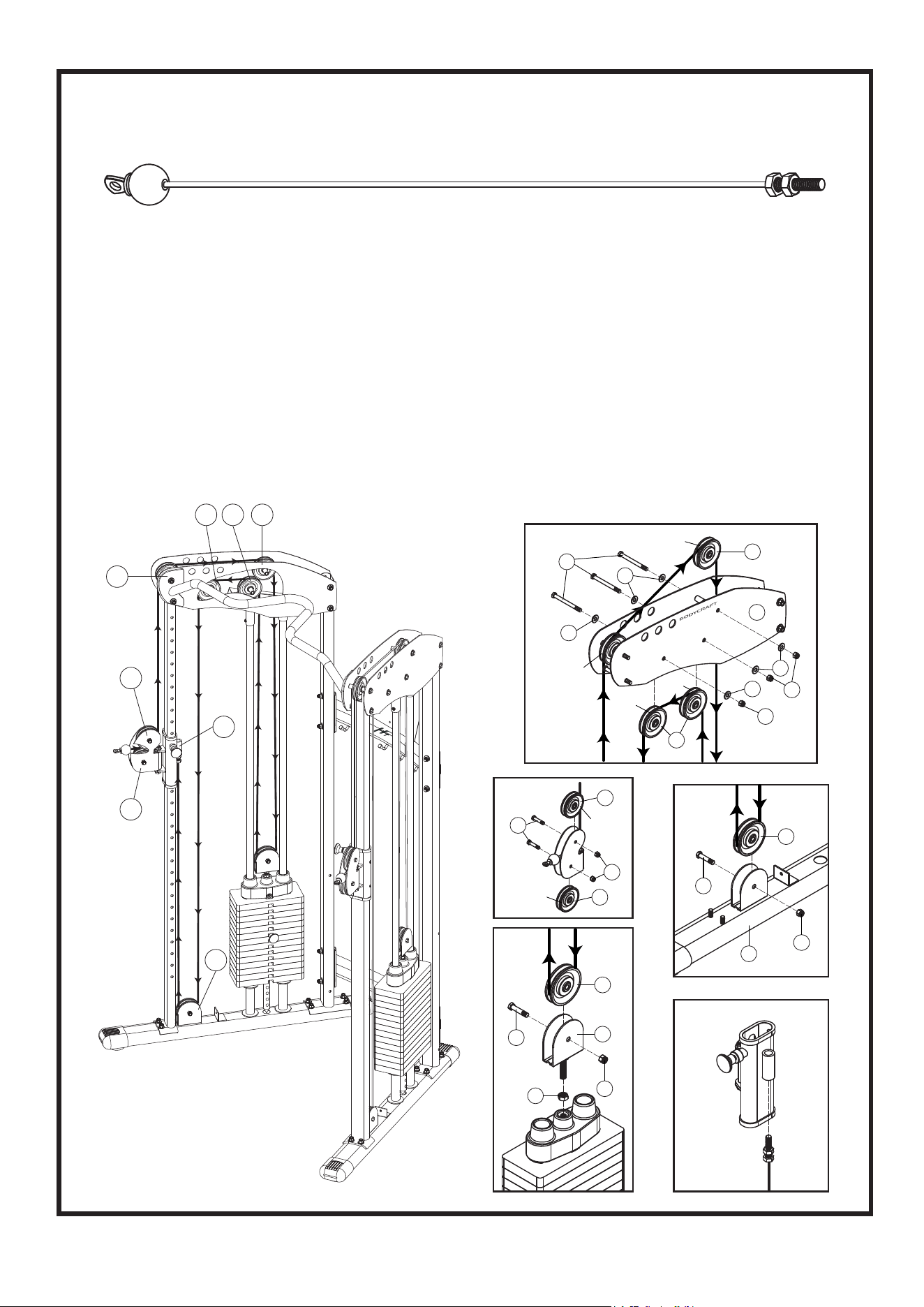
STEP 4
Assemble Cable and Pulleys as shown
9
P1
P9
P2
P3
P4P6
P8
P7
P9
51
P1,P2
P2
P1
69
36
36
53
63
36
63
36
69
69
63
63
6R
P5
36
53
69
18
71
P8
69
1
53
36
1. Insert the Bolt End of the Cable (27) through Rotating Pulley Holder (17)
as Figure P1, P2, route over the two pulleys mounted on the Right Top
Frame (6R) as Figure P3, P4. Then go down and around the Pulley
Block (18) on the top plate as Figure P5.
2. Route the cable up and over two pulleys mounted on the Right Top
Frame (6R) as Figure P6, P7, then down to the pulley mounted at the
Base Frame Leg (1) as Figure P8, and up to screw on the bracket at the
Right Pulley Height Adjuster (15R) as Figure P9.
3. Perform the same procedure for the Left side.
Cable (27)
Ball End Bolt End
1
2
3
4
5
6
7
8
9
1
0
1
1
1
6
1
7
1
8
1
9
2
0
2
1
2
2
2
3
2
4
2
5
2
6
2
7
2
8
2
9
3
0
3
1
1
2
3
4
5
6
7
8
9
1
0
1
1
1
6
1
7
1
8
1
9
2
0
2
1
2
2
2
3
2
4
2
5
2
6
2
7
2
8
2
9
3
0
3
1
1
2
3
4
5
6
7
8
9
1
0
1
1
1
2
1
3
1
4
1
5
1
6
1
7
1
8
1
9
2
0
2
1
2
2
2
3
2
4
2
5
2
6
2
7
2
8
2
9
3
0
3
1
1
2
3
4
5
6
7
8
9
1
0
1
1
1
2
1
3
1
4
1
5
1
6
1
7
1
8
1
9
2
0
2
1
2
2
2
3
2
4
2
5
2
6
2
7
2
8
2
9
3
0
3
1
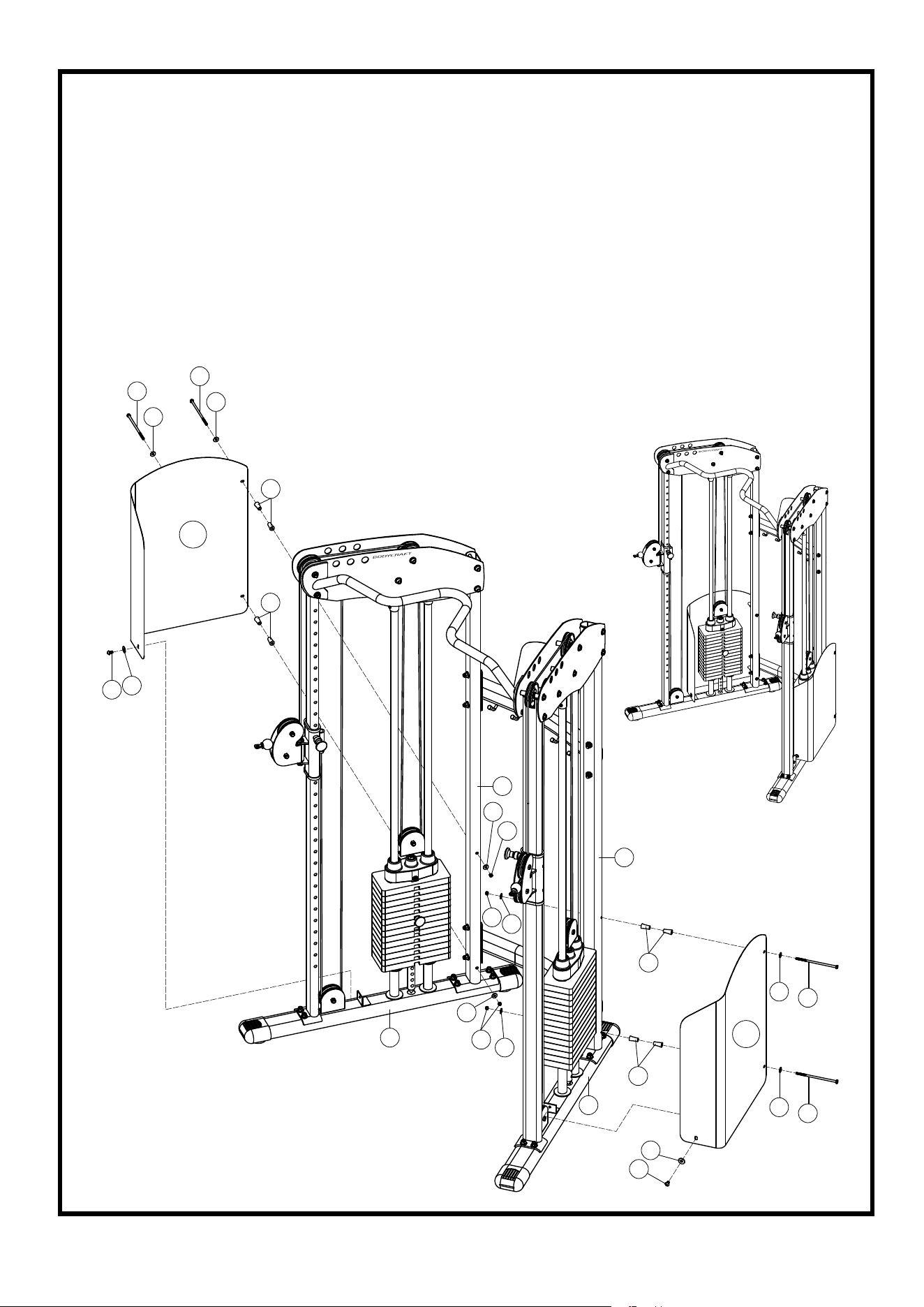
STEP 5
Assemble Right & Left Panel
10
54
66
10R
54
66
43
43
55
65
4
66
66
70
70
4
1
1
70
66
66
66
54
43
66
54
43
11L
1. Attach Right & Left Weight Panel (10R & 11L) to the Rear Upright
Frames (4) using eight Plastic Studs (43), four 1/4" X 6" Hex Bolts
(54), eight 1/4" Washers (66), and four 1/4" Nylon Nuts (70).
2. Attach Right & Left Weight Panel (10R & 11L) to the Base Frame
Leg (1) using two 5/16" X 1/2" Bottom Head Bolts (55) and two 5/16"
Washers (65).
3. Tighten all the bolts from the Base Frame Leg (1) to the top of the
frame.
65
55
1
2
3
4
5
6
7
8
9
1
0
1
6
1
7
1
8
1
9
2
0
2
1
2
2
2
3
2
4
2
5
2
6
2
7
2
8
2
9
3
0
3
1
1
2
3
4
5
6
7
8
9
1
0
1
1
1
2
1
3
1
4
1
5
1
6
1
7
1
8
1
9
2
0
2
1
2
2
2
3
2
4
2
5
2
6
2
7
2
8
2
9
3
0
3
1
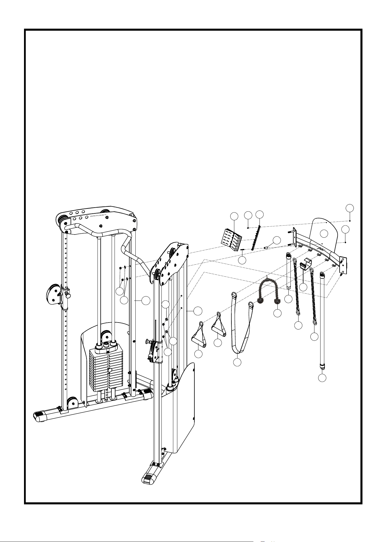
STEP 6
Accessories and Exercise Guide Placement
11
1. Hang two Single Handles (32), Chin Assist Strap (30), Tricep Rope
(31), Sport Bar (12), two Chains (33), Ankle Strap (29), and Long
Bar (13) on the Top Cross Support (8).
2. Attach Exercise Book (28), Exercise Book Holder (26) and Plastic
Studs (43) to the op Cross Support (8) using one M4 X 10L Sunken
Head Screw (59), one M4 X 40L Sunken Head Screw (58) and two
M4 Nylon Nuts (72).
68
62
62
62
68
58
32
32
30
31
12
13
29
33
33
43
8
28
59
26
72
72
3L
2R

Assembly is complete! Please take the following steps before using the gym:
1. Make certain all bolts are tightened securely.
2. Make certain all cables are seated into all pulley grooves. A cable rubbing
against steel will peel the nylon coating, voiding warranty and resulting in a
need for replacement.
3. Pre-stretch the cables. Put the Selector Pin (41) in the bottom hole on the
weight stack. Pull on the cables with great force, helping remove any kinks
and providing any initial cable stretch.
4. Be aware the cables can loosen and slightly stretch upon initial use.
5. The cables should be adjusted as tight as possible, but no so tight as to lift
the Top Plate (19) above the weight stack. Be certain to secure the jam nuts
after adjustments are made.
6. For better performance, apply a household lubricant (such as silicone) to any
adjustable areas and to the Guide Rods (5).
7. Enjoy many years of a Fit Lifestyle.
Thank you for purchasing the BODYCRAFT HFT Strength Training System!
If you have questions or comments, please contact your BodyCraft dealer
or contact BODYCRAFT directly at 800-990-5556 or i[email protected].
Please REGISTER your BODYCRAFT HFT at www.bodycraft.com